
Put the load on us. - Tiger Brand Jack Post Brand Jack Post Catalog... · Put the load on us. TIG...
26
Put the load on us.
Transcript of Put the load on us. - Tiger Brand Jack Post Brand Jack Post Catalog... · Put the load on us. TIG...
Put the load on us.
©Tiger Brand Jack Post 2014TIGER BRAND JACK POST | 330.576.1750 | TigerBrandJackPost.com
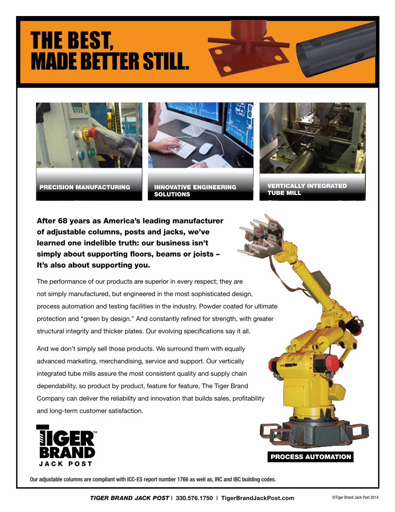
the best, made better still.
The performance of our products are superior in every respect; they are
not simply manufactured, but engineered in the most sophisticated design,
process automation and testing facilities in the industry. Powder coated for ultimate
protection and “green by design.” And constantly refined for strength, with greater
structural integrity and thicker plates. Our evolving specifications say it all.
And we don’t simply sell those products. We surround them with equally
advanced marketing, merchandising, service and support. Our vertically
integrated tube mills assure the most consistent quality and supply chain
dependability, so product by product, feature for feature, The Tiger Brand
Company can deliver the reliability and innovation that builds sales, profitability
and long-term customer satisfaction.
After 68 years as America’s leading manufacturer of adjustable columns, posts and jacks, we’ve learned one indelible truth: our business isn’t simply about supporting floors, beams or joists – It’s also about supporting you.
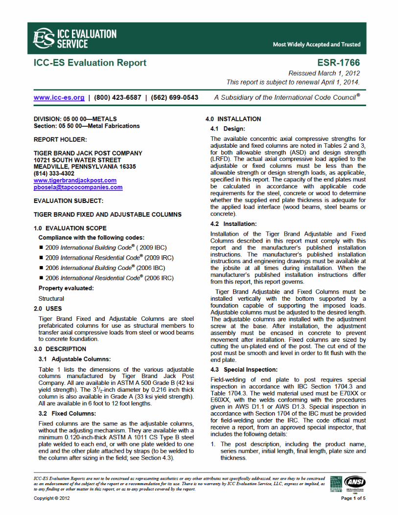
Our adjustable columns are compliant with ICC-ES report number 1766 as well as, IRC and IBC building codes.
Process AutomAtion
innovAtive engineering solutions
Precision mAnufActuring verticAlly integrAted tube mill

©Tiger Brand Jack Post 2014
Double Carriage Bolt & Nut for added safety
Adjusting Screw SAE
Heavy Gauge Steel Plate
PRO SERIES JACK POST 24/5" OD Outside Tube, 2½" OD Inside Tube; 3/16" x 4"x 6" Plates
11 Ga. adjustment RanGe uPC ComPRession Load RanGe* WeiGht unit Cube
J-PRO-100 4' 8" - 8' 4" / 56"-100" 8-38956-00100-638,000 lbs.
to 20,000 lbs.31 lbs. 0.5
*Compression load is testing to the point of failure. Maximum loads are obtained at minimum extension. To determine safe or allowable loads, consult a licensed engineer.
Compression Load Range*
38,000 lbs. to 20,000 lbs.
TIGER BRAND JACK POST | 330.576.1750 | TigerBrandJackPost.com
• 11 gauge inside/outside high carbon steel tubes
• Heavy gauge steel plates
• Double carriage bolt design for added safety
• Corrosion-resistant coating inside & out
• Zinc-coated secure bolt/nut connectors
• Adjustment range from 4' 8" to 8' 4"
• Temporary support for room additions & remodeling projects, with the strength to support large appliances
• Easy to adjust, easy to install
• Can be used permanently as secondary support along with the approved primary support
PRO SERIESjack POSt
our strongest jAck for secure temPorAry
suPPort under the heAviest loAd AreAs.
Designed for heavy load areas, with added strength in every component.
©Tiger Brand Jack Post 2014
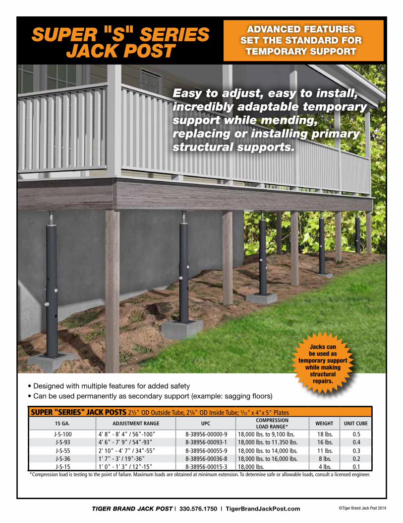
SUPER "SERIES" JACK POSTS 2½" OD Outside Tube, 2¼" OD Inside Tube; 3/32" x 4"x 5" Plates
15 Ga. adjustment RanGe uPCComPRession Load RanGe*
WeiGht unit Cube
J-S-100 4' 8" - 8' 4" / 56"-100" 8-38956-00000-9 18,000 lbs. to 9,100 lbs. 18 lbs. 0.5J-S-93 4' 6" - 7' 9" / 54"-93" 8-38956-00093-1 18,000 lbs. to 11.350 lbs. 16 lbs. 0.4J-S-55 2' 10" - 4' 7" / 34"-55" 8-38956-00055-9 18,000 lbs. to 14,000 lbs. 11 lbs. 0.3J-S-36 1' 7" - 3' / 19"-36" 8-38956-00036-8 18,000 lbs. to 16,000 lbs. 8 lbs. 0.2J-S-15 1' 0" - 1' 3" / 12"-15" 8-38956-00015-3 18,000 lbs. 4 lbs. 0.1
*Compression load is testing to the point of failure. Maximum loads are obtained at minimum extension. To determine safe or allowable loads, consult a licensed engineer.
• Designed with multiple features for added safety• Can be used permanently as secondary support (example: sagging floors)
Jacks can be used as
temporary support while making
structural repairs.
TIGER BRAND JACK POST | 330.576.1750 | TigerBrandJackPost.com
Easy to adjust, easy to install, incredibly adaptable temporary support while mending, replacing or installing primary structural supports.
AdvAnced feAtures set the stAndArd for temPorAry suPPort
SUPER "S" SERIESjack POSt
©Tiger Brand Jack Post 2014TIGER BRAND JACK POST | 330.576.1750 | TigerBrandJackPost.com
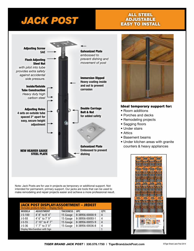
Note: Jack Posts are for use in projects as temporary or additional support. Not intended for permanent, primary support. Our jacks are tools that can be used to make remodeling and repair projects easier and achieve a more professional result.
Galvanized Plate embossed to prevent dishing and movement of post
Immersion Dipped Heavy coating inside and out to prevent corrosion
Double Carriage Bolt & Nut for added safety
Galvanized Plate Embossed to prevent dishing
Adjusting Screw SAE
Flush Adjusting Steel Nut
with pilot into tube provides extra safety
against accidental side pressure.
Inside/Outside Tube ConstructionHeavy duty high
carbon steel
Adjusting Holes4 sets on outside tube
spaced 3" apart for easy, secure height
adjustment
JACK POST DISPLAY/ASSORTMENT – JRD03T(Includes products below + Display Rack)modeL# adjustment thiCkness uPC Qty.J-S-100 4’ 8" to 8’ 4" 15 Gauge 8-38956-00000-9 4J-S-93 4’ 6" to 7’ 9" 15 Gauge 8-38956-00093-1 4J-S-55 2’ 10" to 4’ 7" 15 Gauge 8-38956-00055-9 4J-S-36 1’ 7" to 3’ 0" 15 Gauge 8-38956-00036-8 4Display Merchandiser with Sign 1
NEW HEAvIEr GAuGE STEEl PlATE
ideal temporary support for:• Room additions• Porches and decks• Remodeling projects• Sagging floors• Under stairs• Attics• Basement beams• Under kitchen areas with granite
counters & heavy appliances
jack POStAll steel
AdjustAbleeAsy to instAll

1. Place the flat side of one of the plates on footing. Put the larger diameter post over the plate with the holes oriented at the top (Figure ➊). Reverse for shorter applications. For 12"-15" Jack skip steps 2 and 3.
2. Insert the smaller diameter post inside the larger diameter post. The hole end of the smaller diameter tube is required to be inserted into the outer diameter tube (Figure ➋).
a. Note: For shorter heights, the holes of the larger diameter tube will be at the bottom (i.e. near the footer).
3. Lift the smaller diameter post to provide the tallest assembly height achievable for the given conditions. With the holes aligned between the outside and inside tube, install two carriage bolts through the aligned holes and install the acorn nuts onto the threaded portion of the carriage bolts (Figure ➌).
a. Note: It is imperative that both carriage bolts are installed through the holes of the inside and outside tubing.
4. With the adjusting screw and nut, turn the round nut to the top of the threads of the adjusting screw. Place the adjustment screw on top of the smaller diameter post. The tapered side of the nut will fit into the smaller diameter post with the shoulder of the nut resting on top of the post (Figure ➍).
a. Note: If the assembly was installed too high, it may prevent the installation of the adjusting nut and screw. If this is the case, go back to step 3 and readjust the assembly.
5. Place the other plate on top of the adjusting screw with the flat side of the plate facing up and use an adjustable wrench to complete the fine adjustment (Figure ➎).
Note:
• For best support under wooden structures place the larger diameter tube and plate up against the wooden support (Figure ➏)
• Make sure post is centered under beam and is vertically plumb (straight)
• Secure plates with proper nails, screws or bolts.
• To correct sagging floors, place beam under joists and hold in place with two Telescoping Jacks. Adjust the floor jacks one-half turn each week over several weeks.
• Telescoping jacks should be used as additional support, not the primary means of support.
• When used in a lifting application consult a licensed engineer to determine safe allowable load.
➎
➍
➋
➌
➊
PLATE
RouNd NuT
AdjuSTing ScreW
SMAll diAMeTer poST
cArriAge bolTS And nuTS
lArge diAMeTer
poST
PLATE
➎ ➏
JaCK POstiNstallatiON iNstruCtiONs
➎ ➏
©Tiger Brand Jack Post 2014TIGER BRAND JACK POST | 330.576.1750 | TigerBrandJackPost.com
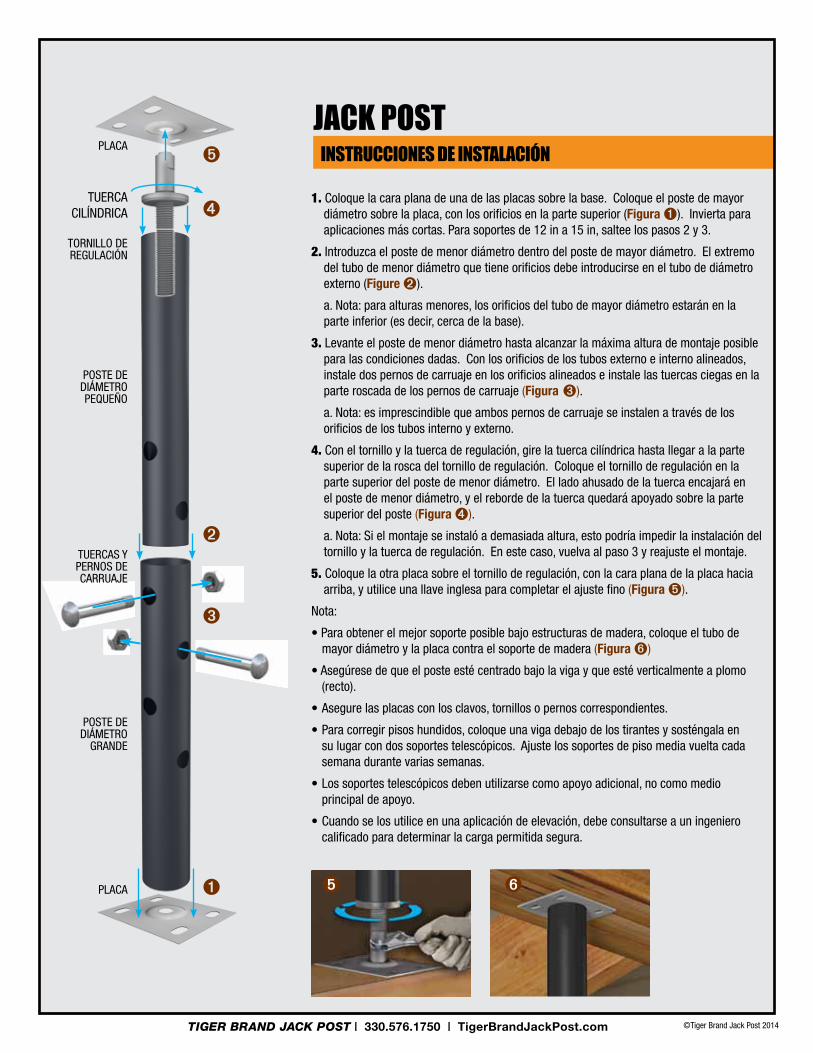
1. coloque la cara plana de una de las placas sobre la base. coloque el poste de mayor diámetro sobre la placa, con los orificios en la parte superior (Figura ➊). Invierta para aplicaciones más cortas. Para soportes de 12 in a 15 in, saltee los pasos 2 y 3.
2. Introduzca el poste de menor diámetro dentro del poste de mayor diámetro. El extremo del tubo de menor diámetro que tiene orificios debe introducirse en el tubo de diámetro externo (Figure ➋).
a. Nota: para alturas menores, los orificios del tubo de mayor diámetro estarán en la parte inferior (es decir, cerca de la base).
3. Levante el poste de menor diámetro hasta alcanzar la máxima altura de montaje posible para las condiciones dadas. con los orificios de los tubos externo e interno alineados, instale dos pernos de carruaje en los orificios alineados e instale las tuercas ciegas en la parte roscada de los pernos de carruaje (Figura ➌).
a. Nota: es imprescindible que ambos pernos de carruaje se instalen a través de los orificios de los tubos interno y externo.
4. con el tornillo y la tuerca de regulación, gire la tuerca cilíndrica hasta llegar a la parte superior de la rosca del tornillo de regulación. coloque el tornillo de regulación en la parte superior del poste de menor diámetro. El lado ahusado de la tuerca encajará en el poste de menor diámetro, y el reborde de la tuerca quedará apoyado sobre la parte superior del poste (Figura ➍).
a. nota: Si el montaje se instaló a demasiada altura, esto podría impedir la instalación del tornillo y la tuerca de regulación. en este caso, vuelva al paso 3 y reajuste el montaje.
5. coloque la otra placa sobre el tornillo de regulación, con la cara plana de la placa hacia arriba, y utilice una llave inglesa para completar el ajuste fino (Figura ➎).
Nota:
• para obtener el mejor soporte posible bajo estructuras de madera, coloque el tubo de mayor diámetro y la placa contra el soporte de madera (Figura ➏)
• Asegúrese de que el poste esté centrado bajo la viga y que esté verticalmente a plomo (recto).
• Asegure las placas con los clavos, tornillos o pernos correspondientes.
• para corregir pisos hundidos, coloque una viga debajo de los tirantes y sosténgala en su lugar con dos soportes telescópicos. Ajuste los soportes de piso media vuelta cada semana durante varias semanas.
• los soportes telescópicos deben utilizarse como apoyo adicional, no como medio principal de apoyo.
• cuando se los utilice en una aplicación de elevación, debe consultarse a un ingeniero calificado para determinar la carga permitida segura.
➎
➍
➋
➌
➊
plAcA
TuercA cilíndricA
ToRNILLo dE regulAción
poSTe de diáMeTro PEquEño
TuercAS y pernoS de cArruAje
poSTe de diáMeTro
grAnde
plAcA
iNstruCCiONes de iNstalaCióN
➎ ➏
JaCK POst
©Tiger Brand Jack Post 2014TIGER BRAND JACK POST | 330.576.1750 | TigerBrandJackPost.com

1. Placez le côté plat d’une des plaques sur le sol. Placez le fût du diamètre le plus élevé sur la plaque avec les trous orientés vers le haut (Figure ➊). Inversez pour les applications plus courtes. Pour les étais de 30 à 38 cm (12 à 15 po) passez les étapes 2 et 3.
2. Insérez le fût du diamètre le plus faible dans le fût du diamètre le plus élevé. Le trou d’extrémité du tube du diamètre le plus faible doit être inséré dans le tube de diamètre extérieur (Figure ➋).
a. Remarque : pour les plus petites hauteurs, les trous du tube du diamètre le plus élevé seront en bas (près de la base).
3. Soulevez le fût du diamètre le plus faible pour obtenir la hauteur la plus grande pouvant être obtenue pour les conditions données. Alignez les trous des tubes extérieur et intérieur. Insérez deux boulons de carrosserie dans l’alignement des trous et placez les écrous borgnes sur la portion filetée des boulons (Figure ➌).
a. Remarque : il est impératif d’insérer les deux boulons de carrosserie dans les trous des tubes intérieur et extérieur.
4. À l’aide de la vis et de l’écrou de réglage, faites tourner l’écrou rond vers le haut du filetage de la vis de réglage. Placez la vis de réglage en haut du fût du diamètre le plus petit. La partie conique de l’écrou s’insère dans le fût du diamètre le plus petit, l’épaulement de l’écrou reposant sur le haut du fût (Figure ➍).
a. Remarque : une installation trop élevée de l’ensemble peut empêcher l’installation de la vis et de l’écrou de réglage. dans ce cas, revenez à l’étape 3 et réajustez l’ensemble.
5. Placez l’autre plaque au-dessus de la vis de réglage, le côté plat de la plaque vers le haut, et utilisez une clé à molette pour affiner le réglage (Figure ➎).
Remarque :
• pour un meilleur soutien sous les structures en bois, placez le tube du plus grand diamètre et la plaque contre le support en bois (Figure ➏)
• Veillez à ce que le fût soit centré sous la poutre et vertical (droit)
• Sécurisez les plaques de manière appropriée avec des clous, des vis ou des chevilles.
• pour corriger des planchers affaissés, placez une poutre sous les solives et maintenez l’ensemble en place avec deux étais télescopiques. Ajustez les étais d’un demi-tour chaque semaine pendant plusieurs semaines.
• les étais télescopiques ne doivent servir que pour un soutien supplémentaire, en aucun cas pour le soutien principal.
• pour une utilisation dans une application de soulèvement, consultez un ingénieur qualifié pour déterminer la charge maximale autorisée.
➎
➍
➋
➌
➊
PLAquE
écrou rond
ViS de réglAge
FûT du diAMèTre
FAible
écrouS eT boulonS de
cArroSSerie
FûT du diAMèTre
éleVé
PLAquE ➎ ➏
iNstruCtiONs d’iNstallatiON
➎ ➏
JaCK POst
©Tiger Brand Jack Post 2014TIGER BRAND JACK POST | 330.576.1750 | TigerBrandJackPost.com
©Tiger Brand Jack Post 2014TIGER BRAND JACK POST | 330.576.1750 | TigerBrandJackPost.com
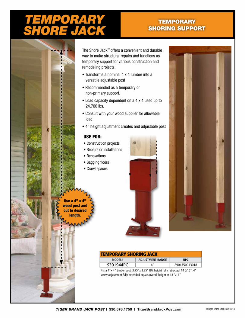
USE foR:• construction projects
• repairs or installations
• renovations
• Sagging floors
• crawl spaces
The Shore jack™ offers a convenient and durable way to make structural repairs and functions as temporary support for various construction and remodeling projects.
• Transforms a nominal 4 x 4 lumber into a versatile adjustable post
• recommended as a temporary or non-primary support.
• load capacity dependent on a 4 x 4 used up to 24,700 lbs.
• consult with your wood supplier for allowable load
• 4" height adjustment creates and adjustable post
TEMPORARY SHORING JACKmodeL# adjustment RanGe uPC
S301944PC 4" 8904750013018
Fits a 4"x 4" timber post (3.75"x 3.75" ID), height fully retracted: 14 5/16", 4" screw adjustment fully extended equals overall height at 18 5/16"
tEMPORaRY SHORE jack
temPorAry shoring suPPort
Use a 4" x 4" wood post and cut to desired
length.
©Tiger Brand Jack Post 2014TIGER BRAND JACK POST | 330.576.1750 | TigerBrandJackPost.com
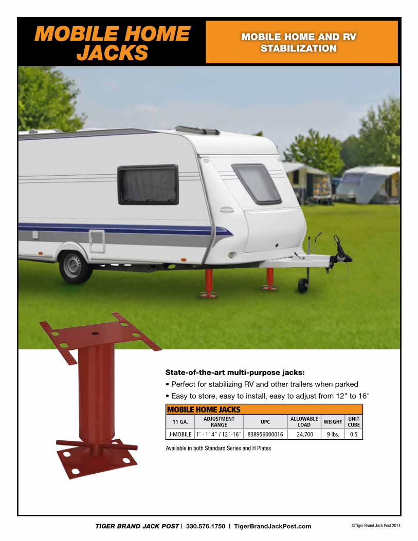
State-of-the-art multi-purpose jacks:
• Perfect for stabilizing RV and other trailers when parked
• Easy to store, easy to install, easy to adjust from 12" to 16"
MOBILE HOME JACKS11 Ga. adjustment
RanGe uPC aLLoWabLe Load WeiGht unit
Cube
J-MOBILE 1' - 1' 4" / 12"-16" 838956000016 24,700 9 lbs. 0.5
Available in both Standard Series and H plates
MOBILE HOME jackS
mobile home And rv stAbiliZAtion

©Tiger Brand Jack Post 2014
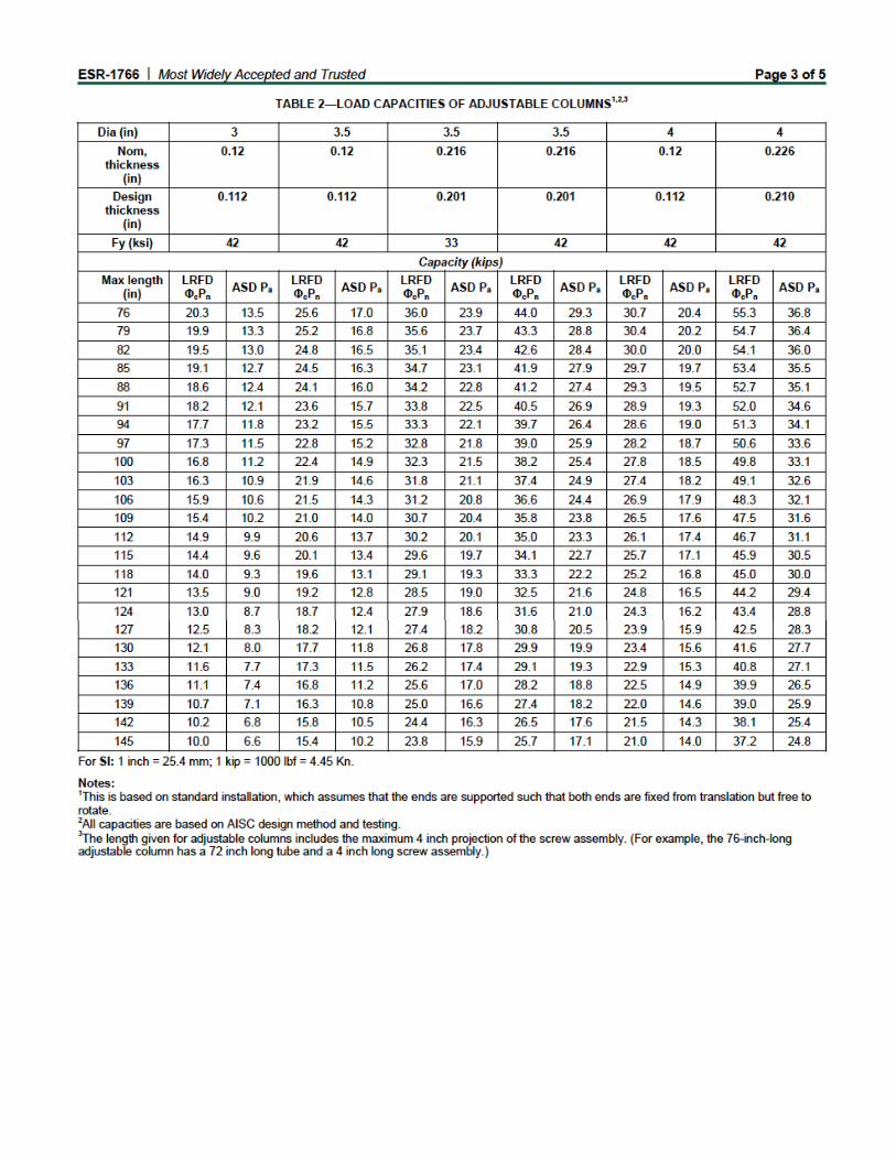
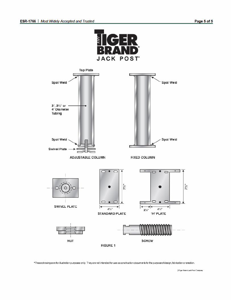
• Adjustable building columns can be installed in about fifteen minutes by a single worker
• Set column perpendicular between footer and beam with adjustment screw on footer; adjust screw until post is firmly in position
• Additional adjustments may be made during construction to maintain level floor
• Tamper proof adjustment... poured concrete floor locks column adjustment permanently when correctly installed
• 11 gauge Adjustable building columns available in 3", 3 ½", 4" od, and 3 ½" od Schedule 40
• corrosion resistant powder coating that exceeds ASTM-b117-85
• lengths available in 3" increments up to 12 feet
• Fully assembled, self-contained, no loose parts
• refer to current icc-eS report for load values
STANDARD END PLATEUSED WITH WOOD BEaMS 4¼" x 7½" x .120" thick
"H" PLATEUSED WITH STEEL BEaMS 4¼" x 7¼" x .120" thick
SWIVEL END PLATE4" x 6" x .120" thick
SCREW: 1¼" O.D., 7 Pitch "V" thread with 4" adjustment
NUT: 3" O.D. tapped for 1¼" 7 pitch thread
TIGER BRAND JACK POST | 330.576.1750 | TigerBrandJackPost.com
ICC-ESR-1766Complies with
IBC and IRCBuilding Codes
aDjUStaBLE BUILDING cOLUMNS
ultimAte strength, ultimAte efficiency for PermAnent
new home construction And remodeling suPPort.
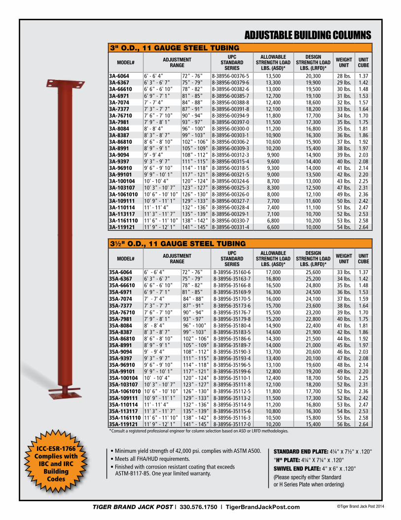
• Minimum yield strength of 42,000 psi. complies with ASTM A500. • Meets all FHA/HUD requirements. • Finished with corrosion resistant coating that exceeds
aSTM-B117-85. One year limited warranty.
STANDArD END PlATE: 4¼" x 7½" x .120"
"H" PlATE: 4¼" x 7¼" x .120"
SWIvEl END PlATE: 4" x 6" x .120"
(please specify either Standard or H Series Plate when ordering)
3" o.d., 11 gAuge steel tubing
ModEl# AdjuStMEnt RAngE
uPC StAndARd
SERiES
AllowAblEStREngtH loAd
lbS. (ASd)*
dESignStREngtH loAd
lbS. (lRFd)*
wEigHt unit
unitCubE
3A-6064 6' - 6' 4" 72" - 76" 8-38956-00376-5 13,500 20,300 28 lbs. 1.373A-6367 6' 3" - 6' 7" 75" - 79" 8-38956-00379-6 13,300 19,900 29 lbs. 1.423A-66610 6' 6" - 6' 10" 78" - 82" 8-38956-00382-6 13,000 19,500 30 lbs. 1.483A-6971 6' 9" - 7' 1" 81" - 85" 8-38956-00385-7 12,700 19,100 31 lbs. 1.533A-7074 7' - 7' 4" 84" - 88" 8-38956-00388-8 12,400 18,600 32 lbs. 1.573A-7377 7' 3" - 7' 7" 87" - 91" 8-38956-00391-8 12,100 18,200 33 lbs. 1.643A-76710 7' 6" - 7' 10" 90" - 94" 8-38956-00394-9 11,800 17,700 34 lbs. 1.703A-7981 7' 9" - 8' 1" 93" - 97" 8-38956-00397-0 11,500 17,300 35 lbs. 1.753A-8084 8' - 8' 4" 96" - 100" 8-38956-00300-0 11,200 16,800 35 lbs. 1.813A-8387 8' 3" - 8' 7" 99" - 103" 8-38956-00303-1 10,900 16,300 36 lbs. 1.863A-86810 8' 6" - 8' 10" 102" - 106" 8-38956-00306-2 10,600 15,900 37 lbs. 1.923A-8991 8' 9" - 9' 1" 105" - 109" 8-38956-00309-3 10,200 15,400 38 lbs. 1.973A-9094 9' - 9' 4" 108" - 112" 8-38956-00312-3 9,900 14,900 39 lbs. 2.033A-9397 9' 3" - 9' 7" 111" - 115" 8-38956-00315-4 9,600 14,400 40 lbs. 2.083A-96910 9' 6" - 9' 10" 114" - 118" 8-38956-00318-5 9,300 14,000 41 lbs. 2.143A-99101 9' 9" - 10' 1" 117" - 121" 8-38956-00321-5 9,000 13,500 42 lbs. 2.203A-100104 10' - 10' 4" 120" - 124" 8-38956-00324-6 8,700 13,000 43 lbs. 2.253A-103107 10' 3" - 10' 7" 123" - 127" 8-38956-00325-3 8,300 12,500 47 lbs. 2.313A-1061010 10' 6" - 10' 10" 126" - 130" 8-38956-00326-0 8,000 12,100 49 lbs. 2.363A-109111 10' 9" - 11' 1" 129" - 133" 8-38956-00327-7 7,700 11,600 50 lbs. 2.423A-110114 11' - 11' 4" 132" - 136" 8-38956-00328-4 7,400 11,100 51 lbs. 2.473A-113117 11' 3" - 11' 7" 135" - 139" 8-38956-00329-1 7,100 10,700 52 lbs. 2.533A-1161110 11' 6" - 11' 10" 138" - 142" 8-38956-00330-7 6,800 10,200 53 lbs. 2.583A-119121 11' 9" - 12' 1" 141" - 145" 8-38956-00331-4 6,600 10,000 54 lbs. 2.64
3½" o.d., 11 gAuge steel tubing
ModEl# AdjuStMEnt RAngE
uPC StAndARd
SERiES
AllowAblEStREngtH loAd
lbS. (ASd)*
dESignStREngtH loAd
lbS. (lRFd)*
wEigHt unit
unitCubE
35A-6064 6' - 6' 4" 72" - 76" 8-38956-35160-6 17,000 25,600 33 lbs. 1.3735A-6367 6' 3" - 6' 7" 75" - 79" 8-38956-35163-7 16,800 25,200 34 lbs. 1.4235A-66610 6' 6" - 6' 10" 78" - 82" 8-38956-35166-8 16,500 24,800 35 lbs. 1.4835A-6971 6' 9" - 7' 1" 81" - 85" 8-38956-35169-9 16,300 24,500 36 lbs. 1.5335A-7074 7' - 7' 4" 84" - 88" 8-38956-35170-5 16,000 24,100 37 lbs. 1.5935A-7377 7' 3" - 7' 7" 87" - 91" 8-38956-35173-6 15,700 23,600 38 lbs. 1.6435A-76710 7' 6" - 7' 10" 90" - 94" 8-38956-35176-7 15,500 23,200 39 lbs. 1.7035A-7981 7' 9" - 8' 1" 93" - 97" 8-38956-35179-8 15,200 22,800 40 lbs. 1.7535A-8084 8' - 8' 4" 96" - 100" 8-38956-35180-4 14,900 22,400 41 lbs. 1.8135A-8387 8' 3" - 8' 7" 99" - 103" 8-38956-35183-5 14,600 21,900 42 lbs. 1.8635A-86810 8' 6" - 8' 10" 102" - 106" 8-38956-35186-6 14,300 21,500 44 lbs. 1.9235A-8991 8' 9" - 9' 1" 105" - 109" 8-38956-35189-7 14,000 21,000 45 lbs. 1.9735A-9094 9' - 9' 4" 108" - 112" 8-38956-35190-3 13,700 20,600 46 lbs. 2.0335A-9397 9' 3" - 9' 7" 111" - 115" 8-38956-35193-4 13,400 20,100 47 lbs. 2.0835A-96910 9' 6" - 9' 10" 114" - 118" 8-38956-35196-5 13,100 19,600 48 lbs. 2.1435A-99101 9' 9" - 10' 1" 117" - 121" 8-38956-35199-6 12,800 19,200 49 lbs. 2.2035A-100104 10' - 10' 4" 120" - 124" 8-38956-35110-1 12,400 18,700 50 lbs. 2.2535A-103107 10' 3" - 10' 7" 123" - 127" 8-38956-35111-8 12,100 18,200 52 lbs. 2.3135A-1061010 10' 6" - 10' 10" 126" - 130" 8-38956-35112-5 11,800 17,700 52 lbs. 2.3635A-109111 10' 9" - 11' 1" 129" - 133" 8-38956-35113-2 11,500 17,300 52 lbs. 2.4235A-110114 11' - 11' 4" 132" - 136" 8-38956-35114-9 11,200 16,800 53 lbs. 2.4735A-113117 11' 3" - 11' 7" 135" - 139" 8-38956-35115-6 10,800 16,300 54 lbs. 2.5335A-1161110 11' 6" - 11' 10" 138" - 142" 8-38956-35116-3 10,500 15,800 55 lbs. 2.5835A-119121 11' 9" - 12' 1" 141" - 145" 8-38956-35117-0 10,200 15,400 56 lbs. 2.64*Consult a registered professional engineer for column selection based on aSD or LRFD methodologies.
adJustable buildiNG COlumNs
ICC-ESR-1766Complies with
IBC and IRCBuilding
Codes
©Tiger Brand Jack Post 2014TIGER BRAND JACK POST | 330.576.1750 | TigerBrandJackPost.com
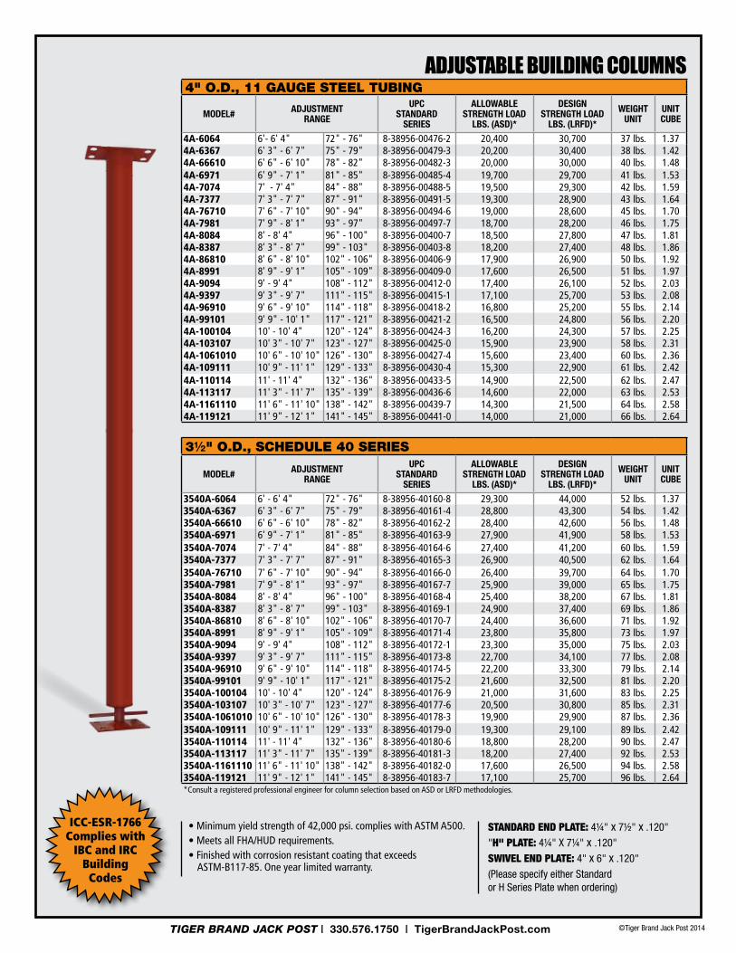
adJustable buildiNG COlumNs4" o.d., 11 gAuge steel tubing
ModEl# AdjuStMEnt RAngE
uPC StAndARd
SERiES
AllowAblEStREngtH loAd
lbS. (ASd)*
dESignStREngtH loAd
lbS. (lRFd)*
wEigHt unit
unitCubE
4A-6064 6'- 6' 4" 72" - 76" 8-38956-00476-2 20,400 30,700 37 lbs. 1.374A-6367 6' 3" - 6' 7" 75" - 79" 8-38956-00479-3 20,200 30,400 38 lbs. 1.424A-66610 6' 6" - 6' 10" 78" - 82" 8-38956-00482-3 20,000 30,000 40 lbs. 1.484A-6971 6' 9" - 7' 1" 81" - 85" 8-38956-00485-4 19,700 29,700 41 lbs. 1.534A-7074 7' - 7' 4" 84" - 88" 8-38956-00488-5 19,500 29,300 42 lbs. 1.594A-7377 7' 3" - 7' 7" 87" - 91" 8-38956-00491-5 19,300 28,900 43 lbs. 1.644A-76710 7' 6" - 7' 10" 90" - 94" 8-38956-00494-6 19,000 28,600 45 lbs. 1.704A-7981 7' 9" - 8' 1" 93" - 97" 8-38956-00497-7 18,700 28,200 46 lbs. 1.754A-8084 8' - 8' 4" 96" - 100" 8-38956-00400-7 18,500 27,800 47 lbs. 1.814A-8387 8' 3" - 8' 7" 99" - 103" 8-38956-00403-8 18,200 27,400 48 lbs. 1.864A-86810 8' 6" - 8' 10" 102" - 106" 8-38956-00406-9 17,900 26,900 50 lbs. 1.924A-8991 8' 9" - 9' 1" 105" - 109" 8-38956-00409-0 17,600 26,500 51 lbs. 1.974A-9094 9' - 9' 4" 108" - 112" 8-38956-00412-0 17,400 26,100 52 lbs. 2.034A-9397 9' 3" - 9' 7" 111" - 115" 8-38956-00415-1 17,100 25,700 53 lbs. 2.084A-96910 9' 6" - 9' 10" 114" - 118" 8-38956-00418-2 16,800 25,200 55 lbs. 2.144A-99101 9' 9" - 10' 1" 117" - 121" 8-38956-00421-2 16,500 24,800 56 lbs. 2.204A-100104 10' - 10' 4" 120" - 124" 8-38956-00424-3 16,200 24,300 57 lbs. 2.254A-103107 10' 3" - 10' 7" 123" - 127" 8-38956-00425-0 15,900 23,900 58 lbs. 2.314A-1061010 10' 6" - 10' 10" 126" - 130" 8-38956-00427-4 15,600 23,400 60 lbs. 2.364A-109111 10' 9" - 11' 1" 129" - 133" 8-38956-00430-4 15,300 22,900 61 lbs. 2.424A-110114 11' - 11' 4" 132" - 136" 8-38956-00433-5 14,900 22,500 62 lbs. 2.474A-113117 11' 3" - 11' 7" 135" - 139" 8-38956-00436-6 14,600 22,000 63 lbs. 2.534A-1161110 11' 6" - 11' 10" 138" - 142" 8-38956-00439-7 14,300 21,500 64 lbs. 2.584A-119121 11' 9" - 12' 1" 141" - 145" 8-38956-00441-0 14,000 21,000 66 lbs. 2.64
3½" o.d., schedule 40 series
ModEl# AdjuStMEnt RAngE
uPC StAndARd
SERiES
AllowAblEStREngtH loAd
lbS. (ASd)*
dESignStREngtH loAd
lbS. (lRFd)*
wEigHt unit
unitCubE
3540A-6064 6' - 6' 4" 72" - 76" 8-38956-40160-8 29,300 44,000 52 lbs. 1.373540A-6367 6' 3" - 6' 7" 75" - 79" 8-38956-40161-4 28,800 43,300 54 lbs. 1.423540A-66610 6' 6" - 6' 10" 78" - 82" 8-38956-40162-2 28,400 42,600 56 lbs. 1.483540A-6971 6' 9" - 7' 1" 81" - 85" 8-38956-40163-9 27,900 41,900 58 lbs. 1.533540A-7074 7' - 7' 4" 84" - 88" 8-38956-40164-6 27,400 41,200 60 lbs. 1.593540A-7377 7' 3" - 7' 7" 87" - 91" 8-38956-40165-3 26,900 40,500 62 lbs. 1.643540A-76710 7' 6" - 7' 10" 90" - 94" 8-38956-40166-0 26,400 39,700 64 lbs. 1.703540A-7981 7' 9" - 8' 1" 93" - 97" 8-38956-40167-7 25,900 39,000 65 lbs. 1.753540A-8084 8' - 8' 4" 96" - 100" 8-38956-40168-4 25,400 38,200 67 lbs. 1.813540A-8387 8' 3" - 8' 7" 99" - 103" 8-38956-40169-1 24,900 37,400 69 lbs. 1.863540A-86810 8' 6" - 8' 10" 102" - 106" 8-38956-40170-7 24,400 36,600 71 lbs. 1.923540A-8991 8' 9" - 9' 1" 105" - 109" 8-38956-40171-4 23,800 35,800 73 lbs. 1.973540A-9094 9' - 9' 4" 108" - 112" 8-38956-40172-1 23,300 35,000 75 lbs. 2.033540A-9397 9' 3" - 9' 7" 111" - 115" 8-38956-40173-8 22,700 34,100 77 lbs. 2.083540A-96910 9' 6" - 9' 10" 114" - 118" 8-38956-40174-5 22,200 33,300 79 lbs. 2.143540A-99101 9' 9" - 10' 1" 117" - 121" 8-38956-40175-2 21,600 32,500 81 lbs. 2.203540A-100104 10' - 10' 4" 120" - 124" 8-38956-40176-9 21,000 31,600 83 lbs. 2.253540A-103107 10' 3" - 10' 7" 123" - 127" 8-38956-40177-6 20,500 30,800 85 lbs. 2.313540A-1061010 10' 6" - 10' 10" 126" - 130" 8-38956-40178-3 19,900 29,900 87 lbs. 2.363540A-109111 10' 9" - 11' 1" 129" - 133" 8-38956-40179-0 19,300 29,100 89 lbs. 2.423540A-110114 11' - 11' 4" 132" - 136" 8-38956-40180-6 18,800 28,200 90 lbs. 2.473540A-113117 11' 3" - 11' 7" 135" - 139" 8-38956-40181-3 18,200 27,400 92 lbs. 2.533540A-1161110 11' 6" - 11' 10" 138" - 142" 8-38956-40182-0 17,600 26,500 94 lbs. 2.583540A-119121 11' 9" - 12' 1" 141" - 145" 8-38956-40183-7 17,100 25,700 96 lbs. 2.64*Consult a registered professional engineer for column selection based on aSD or LRFD methodologies.
• Minimum yield strength of 42,000 psi. complies with ASTM A500. • Meets all FHA/HUD requirements. • Finished with corrosion resistant coating that exceeds
aSTM-B117-85. One year limited warranty.
STANDArD END PlATE: 4¼" x 7½" x .120"
"H" PlATE: 4¼" x 7¼" x .120"
SWIvEl END PlATE: 4" x 6" x .120"
(please specify either Standard or H Series Plate when ordering)
ICC-ESR-1766Complies with
IBC and IRCBuilding
Codes
©Tiger Brand Jack Post 2014TIGER BRAND JACK POST | 330.576.1750 | TigerBrandJackPost.com

installation Time: Approximately 15 MinutesTools Required: None
1. choose the correct size and strength column for the project based on construction document.
2. Adjust screw to slightly short of the length needed between footer and load carrying beam at installation location (Figure ➊).
3. Place column vertically between footer and beam with the adjustment nut and screw on the footer (adjustable end down) (Figure ➋).
4. Adjust screw to wedge the column between footer and beam, tighten until Mono-post is firmly centered directly under the load carrying beam and the footer below (Figure ➌).
5. Additional screw adjustments may be made during construction to keep floor level
6. Poured concrete basement floor permanently locks column adjustment (Figure ➍).
TAMper prooF AdjuSTMenT: coluMn SHould be poSiTioned WiTH AdjuSTMenT nuT And ScreW AT THe FooTer.
LoAd cArrying
beAM
FooTER
note: Always consult local building codes for specific installation requirements in your area.
➋
AdjuSTMenT nuT And ScreW
➊ ➍
➌
adJustable COlumNs
iNstallatiON iNstruCtiONs
©Tiger Brand Jack Post 2014TIGER BRAND JACK POST | 330.576.1750 | TigerBrandJackPost.com
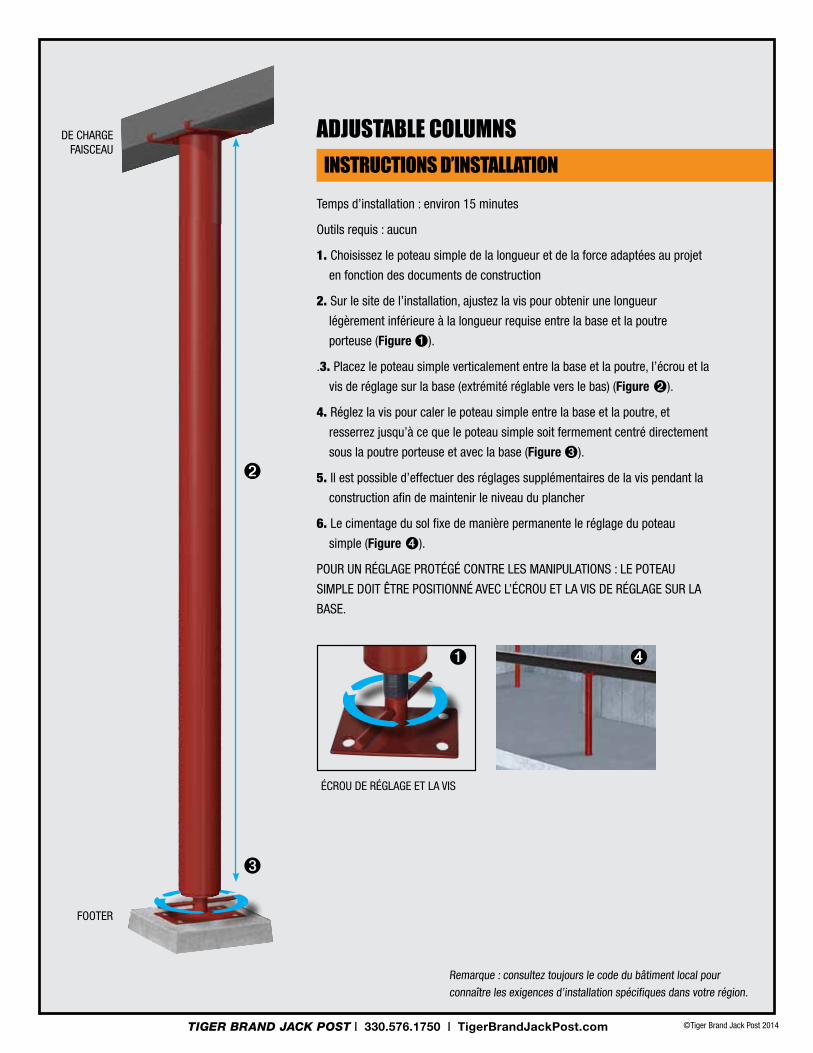
Temps d’installation : environ 15 minutes
outils requis : aucun
1. choisissez le poteau simple de la longueur et de la force adaptées au projet
en fonction des documents de construction
2. Sur le site de l’installation, ajustez la vis pour obtenir une longueur
légèrement inférieure à la longueur requise entre la base et la poutre
porteuse (Figure ➊).
.3. Placez le poteau simple verticalement entre la base et la poutre, l’écrou et la
vis de réglage sur la base (extrémité réglable vers le bas) (Figure ➋).
4. Réglez la vis pour caler le poteau simple entre la base et la poutre, et
resserrez jusqu’à ce que le poteau simple soit fermement centré directement
sous la poutre porteuse et avec la base (Figure ➌).
5. Il est possible d’effectuer des réglages supplémentaires de la vis pendant la
construction afin de maintenir le niveau du plancher
6. Le cimentage du sol fixe de manière permanente le réglage du poteau
simple (Figure ➍).
pour un réglAge proTégé conTre leS MAnipulATionS : le poTeAu
SiMple doiT ÊTre poSiTionné AVec l’écrou eT lA ViS de réglAge Sur lA
bASe.
de cHArge FAiSceAu
FooTER
Remarque : consultez toujours le code du bâtiment local pour
connaître les exigences d’installation spécifiques dans votre région.
➋
écrou de réglAge eT lA ViS
➊ ➍
➌
iNstruCtiONs d’iNstallatiON
adJustable COlumNs
©Tiger Brand Jack Post 2014TIGER BRAND JACK POST | 330.576.1750 | TigerBrandJackPost.com
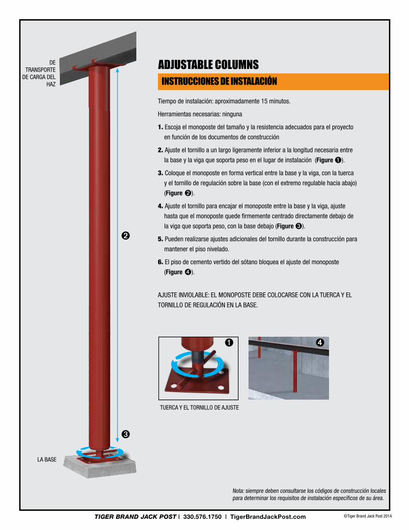
Tiempo de instalación: aproximadamente 15 minutos.
Herramientas necesarias: ninguna
1. Escoja el monoposte del tamaño y la resistencia adecuados para el proyecto
en función de los documentos de construcción
2. Ajuste el tornillo a un largo ligeramente inferior a la longitud necesaria entre
la base y la viga que soporta peso en el lugar de instalación (Figure ➊).
3. coloque el monoposte en forma vertical entre la base y la viga, con la tuerca
y el tornillo de regulación sobre la base (con el extremo regulable hacia abajo)
(Figure ➋).
4. Ajuste el tornillo para encajar el monoposte entre la base y la viga, ajuste
hasta que el monoposte quede firmemente centrado directamente debajo de
la viga que soporta peso, con la base debajo (Figure ➌).
5. pueden realizarse ajustes adicionales del tornillo durante la construcción para
mantener el piso nivelado.
6. el piso de cemento vertido del sótano bloquea el ajuste del monoposte
(Figure ➍).
AjuSTe inViolAble: el MonopoSTe debe colocArSe con lA TuercA y el
Tornillo de regulAción en lA bASe.
dE TrAnSporTe
de cArgA del HAz
lA bASe
nota: siempre deben consultarse los códigos de construcción locales para determinar los requisitos de instalación específicos de su área.
➋
TuercA y el Tornillo de AjuSTe
➊ ➍
➌
iNstruCCiONes de iNstalaCióN
adJustable COlumNs
©Tiger Brand Jack Post 2014TIGER BRAND JACK POST | 330.576.1750 | TigerBrandJackPost.com

©Tiger Brand Jack Post 2014TIGER BRAND JACK POST | 330.576.1750 | TigerBrandJackPost.com
State-of-the-art multi-purpose jacks:• Ideal permanent support for
crawl spaces, under windows and tight confines
• Easy to store, easy to install, easy to adjust
comPAct PermAnent suPPort for renovAtions And
construction Projects.
MINI COLUMNSno. uPC no. uPC desCRiPtion aLLoWabLe
Load3a-1014 838956001013 3a-1014-2 838956001167 3" 1'0" - 1'4" Mini Column 24,700 3a-1418 838956001020 3a-1418-2 838956001174 3" 1'4" - 1'8" Mini Column 24,700 3a-1820 838956001037 3a-1820-2 838956001181 3" 1'8"- 2'0" Mini Column 24,700 3a-2024 838956001044 3a-2024-2 838956001198 3" 2'0"- 2'4" Mini Column 23,700 3a-2428 838956001051 3a-2428-2 838956001204 3" 2'4" - 2'8" Mini Column 23,700 3a-2830 838956001068 3a-2830-2 838956001211 3" 2'8" - 3'0" Mini Column 23,700 3a-3034 838956001075 3a-3034-2 838956001228 3" 3'0" - 3'4" Mini Column 22,300 3a-3438 838956001082 3a-3438-2 838956001235 3" 3'4" - 3'8" Mini Column 22,300 3a-3840 838956001099 3a-3840-2 838956001242 3" 3'8" - 4'0" Mini Column 22,300 3a-4044 838956001105 3a-4044-2 838956001259 3" 4'0" - 4'4" Mini Column 20,700 3a-4448 838956001112 3a-4448-2 838956001266 3" 4'4" - 4'8" Mini Column 20,700 3a-4850 838956001129 3a-4850-2 838956001273 3" 4'8" - 5'0" Mini Column 20,700 3a-5054 838956001136 3a-5054-2 838956001280 3" 5'0" - 5'4" Mini Column 18,800 3a-5458 838956001143 3a-5458-2 838956001297 3" 5'4" - 5'8" Mini Column 18,800 3a-5860 838956001150 3a-5860-2 838956001303 3" 5'8" - 6'0' Mini Column 18,800
Available in both Standard Series and H plates
MINI cOLUMNS
©Tiger Brand Jack Post 2014TIGER BRAND JACK POST | 330.576.1750 | TigerBrandJackPost.com
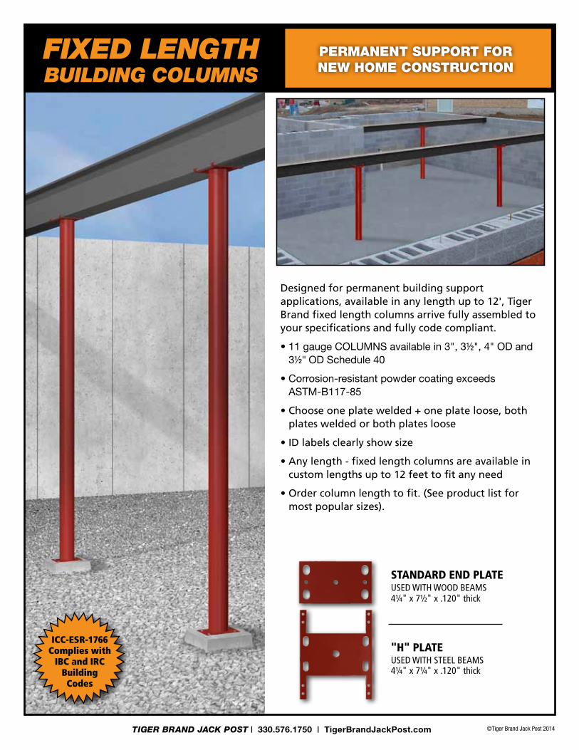
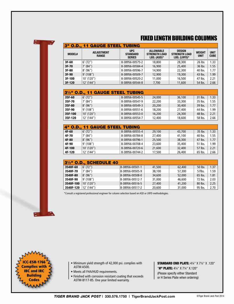
Designed for permanent building support applications, available in any length up to 12', Tiger Brand fixed length columns arrive fully assembled to your specifications and fully code compliant.
• 11 gauge COLUMNS available in 3", 3½", 4" OD and 3½" OD Schedule 40
• Corrosion-resistant powder coating exceeds ASTM-B117-85
• Choose one plate welded + one plate loose, both plates welded or both plates loose
• ID labels clearly show size
• Any length - fixed length columns are available in custom lengths up to 12 feet to fit any need
• Order column length to fit. (See product list for most popular sizes).
STANDARD END PLATEUSED WITH WOOD BEaMS 4¼" x 7½" x .120" thick
"H" PLATEUSED WITH STEEL BEaMS 4¼" x 7¼" x .120" thick
FIXED LENGtH BUILDING cOLUMNS
PermAnent suPPort for new home construction
ICC-ESR-1766Complies with
IBC and IRCBuilding
Codes
3" o.d., 11 gAuge steel tubing
ModEl# AdjuStMEnt RAngE
uPC StAndARd
SERiES
AllowAblEStREngtH loAd
lbS. (ASd)*
dESignStREngtH loAd
lbS. (lRFd)*
wEigHt unit
unitCubE
3F-60 6' (72") 8-38956-00575-2 18,800 28,300 26 lbs 1.333F-70 7' (84") 8-38956-00584-4 16,900 25,400 36 lbs 1.553F-80 8' (96") 8-38956-00596-7 14,900 22,300 40 lbs. 1.773F-90 9' (108") 8-38956-00509-7 12,900 19,300 43 lbs. 1.993F-100 10' (120") 8-38956-00520-2 11,000 16,500 47 lbs. 2.213F-120 12' (144") 8-38956-00544-8 7,700 11,600 54 lbs. 2.66
3½" o.d., 11 gAuge steel tubing35F-60 6' (72") 8-38956-00545-5 24,000 36,100 31 lbs. 1.3335F-70 7' (84") 8-38956-00547-9 22,200 33,300 35 lbs. 1.5535F-80 8' (96") 8-38956-00549-3 20,200 30,400 39 lbs. 1.7735F-90 9' (108") 8-38956-00551-6 18,200 27,400 44 lbs. 1.9935F-100 10' (120") 8-38956-00553-0 16,200 24,300 48 lbs. 2.2135F-120 12' (144") 8-38956-00554-7 12,400 18,600 58 lbs. 2.66
4" o.d., 11 gAuge steel tubing4F-60 6' (72") 8-38956-00555-4 29,100 43,700 35 lbs 1.334F-70 7' (84") 8-38956-00784-8 27,400 41,100 40 lbs. 1.554F-80 8' (96") 8-38956-00796-1 25,500 38,300 47 lbs. 1.774F-90 9' (108") 8-38956-00708-4 23,600 35,400 51 lbs. 1.994F-100 10' (120") 8-38956-00720-6 21,600 32,400 57 lbs. 2.214F-120 12' (144") 8-38956-00744-2 17,500 26,400 65 lbs. 2.66
3½" o.d., schedule 403540F-60 6' (72") 8-38956-00501-1 41,500 62,400 50 lbs 1.373540F-70 7' (84") 8-38956-00505-9 38,100 57,300 57lbs. 1.593540F-80 8' (96") 8-38956-00508-0 34,600 52,000 65 lbs. 1.813540F-90 9' (108") 8-38956-00512-7 31,000 46,600 72 lbs. 2.033540F-100 10' (120") 8-38956-00516-5 27,400 41,200 80 lbs. 2.253540F-120 12' (144") 8-38956-00517-2 20,600 31,000 95 lbs. 2.70
*Consult a registered professional engineer for column selection based on aSD or LRFD methodologies.
• Minimum yield strength of 42,000 psi. complies with aSTM a500.
• Meets all FHA/HUD requirements. • Finished with corrosion resistant coating that exceeds
aSTM-B117-85. One year limited warranty.
FiXed leNGth buildiNG COlumNs
STANDArD END PlATE: 4¼" x 7½" x .120"
"H" PlATE: 4¼" x 7¼" x.120"
(please specify either Standard or H Series plate when ordering)
ICC-ESR-1766Complies with
IBC and IRCBuilding
Codes
©Tiger Brand Jack Post 2014TIGER BRAND JACK POST | 330.576.1750 | TigerBrandJackPost.com

©Tiger Brand Jack Post 2014TIGER BRAND JACK POST | 330.576.1750 | TigerBrandJackPost.com
GRABBER SADDLE PLATEPaRt# dimensions uPC sheLf PaCk Wt.PC.
SP5716 5 3/8" W x 3 9/16" H x 8" L 8-90475-001716-0 12 3.7 lbs.SP3916 3 5/8" W x 3 9/16" H x 8" L 8-90475-001916-4 12 2.4 lbs.
if you are using a laminated (lVl) or dimensional lumber beam, you must use a saddle plate in conjunction with Adjustable Steel columns per Wisconsin udc (uniform dwelling code).
com21.22(3)(d) lateral restraint for all wood beams shall be provided at all columns using a saddle plate or other approved connection where the beam meets one of the following conditions: 1. The beam is not restrained at both ends. 2. The beam is more than 11¼ inches deep using actual measurement.
tHE GRaBBER SaDDLE PLatE
sAddle PlAte for lAminAted (lvl) or
dimensionAl lumber beAms.
• The Grabber Saddle Plate provides lateral support for dimensional lumber beams and prevents the beam from torquing
• Allows for the through connection of fasteners into the side of the wood beam
• Some municipalities have required the use of a saddle plate for dimensional lumber or LVL beams in conjunction with Adjustable Steel Columns
©Tiger Brand Jack Post 2014TIGER BRAND JACK POST | 330.576.1750 | TigerBrandJackPost.com
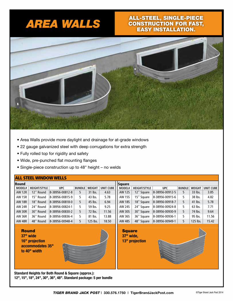
Standard Heights for both Round & Square (approx.):12", 15", 18", 24", 30", 36", 48". Standard package: 5 per bundle
• Area Walls provide more daylight and drainage for at-grade windows
• 22 gauge galvanized steel with deep corrugations for extra strength
• Fully rolled top for rigidity and safety
• Wide, pre-punched flat mounting flanges
• Single-piece construction up to 48" height – no welds
All-steel, single-Piece construction for fAst,
eAsy instAllAtion.
RoundmodeL# heiGht/styLe uPC bundLe WeiGht unit CubeaW 12R 12" Round 8-38956-00812-8 5 31 lbs. 4.63aW 15R 15" Round 8-38956-00815-9 5 43 lbs. 5.78aW 18R 18" Round 8-38956-00818-0 5 45 lbs. 6.94aW 24R 24" Round 8-38956-00824-1 5 59 lbs. 9.25aW 30R 30" Round 8-38956-00830-2 5 72 lbs. 11.56aW 36R 36" Round 8-38956-00836-4 5 81 lbs. 13.88aW 48R 48" Round 8-38956-00948-4 5 125 lbs. 18.50
SquaremodeL# heiGht/styLe uPC bundLe WeiGht unit CubeaW 12S 12" Square 8-38956-00912-5 5 33 lbs. 3.85aW 15S 15" Square 8-38956-00915-6 5 38 lbs. 4.82aW 18S 18" Square 8-38956-00918-7 5 41 lbs. 5.78aW 24S 24" Square 8-38956-00924-8 5 63 lbs. 7.71aW 30S 30" Square 8-38956-00930-9 5 74 lbs. 9.64aW 36S 36" Square 8-38956-00936-1 5 95 lbs. 11.56aW 48S 48" Square 8-38956-00949-1 5 125 lbs. 15.42
ALL STEEL WINDOW WELLS
square37" wide, 13" projection
round37" wide 16" projection accommodates 35" to 40" width
aREa WaLLS


![Brand. Post. Source: Jump start your job in 15 minutes [Webcast]](https://static.fdocuments.in/doc/165x107/5884116d1a28ab95518b5e45/brand-post-source-jump-start-your-job-in-15-minutes-webcast.jpg)


![Brand. Post. Source: Build your Brand in 15 Minutes [Webcast]](https://static.fdocuments.in/doc/165x107/58f05d311a28abff2e8b459f/brand-post-source-build-your-brand-in-15-minutes-webcast.jpg)