Pushing the oil recovery factor (OMC 2011) can ultra compact separation... · – Inlet InLine...
20
Pushing the oil recovery factor (OMC 2011) How can ultra compact separation solutions help? March 24 th 2011, Ravenna, Italy Erica de Haas [email protected] FMC Technologies/CDS Separation Systems
-
Upload
nguyentram -
Category
Documents
-
view
215 -
download
1
Transcript of Pushing the oil recovery factor (OMC 2011) can ultra compact separation... · – Inlet InLine...

Pushing the oil recovery factor (OMC 2011)How can ultra compact separation solutions help?
March 24th 2011, Ravenna, Italy
Erica de Haas [email protected] Technologies/CDS Separation Systems
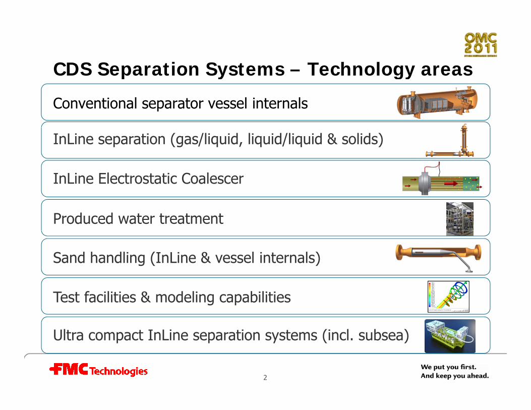
CDS Separation Systems – Technology areasp y gy
Conventional separator vessel internals
InLine separation (gas/liquid, liquid/liquid & solids)
InLine Electrostatic CoalescerInLine Electrostatic Coalescer
Produced water treatment
Sand handling (InLine & vessel internals)
Ultra compact InLine separation systems (incl subsea)
Test facilities & modeling capabilities
2
Ultra compact InLine separation systems (incl. subsea)

How can ultra compact separation help? How can ultra compact separation help? E h i b fi ld il d bli fi ld d lEnhancing brownfield oil recovery and enabling greenfield development
• Brownfield challenges– Constrained topside facilities
– Increased water production
– Declining oil & gas production– Declining oil & gas production
• Green field challenges– Heavy oilHeavy oil
– Low reservoir pressure
– Hydrate formation
IOR ith l i ti
3
• IOR with cyclonic separation

InLine cyclonic separation technologyy p gy
• Stokes:dcs
s
gdv
µρρ
18*2 −
=dµ18
Cyclonic technologyswirling flow
Swirling flow
gincreased G-force
decreased residence time d d f d hdecreased footprint and weight
increased safety, decreased inventory
pipe code
4
pipe code
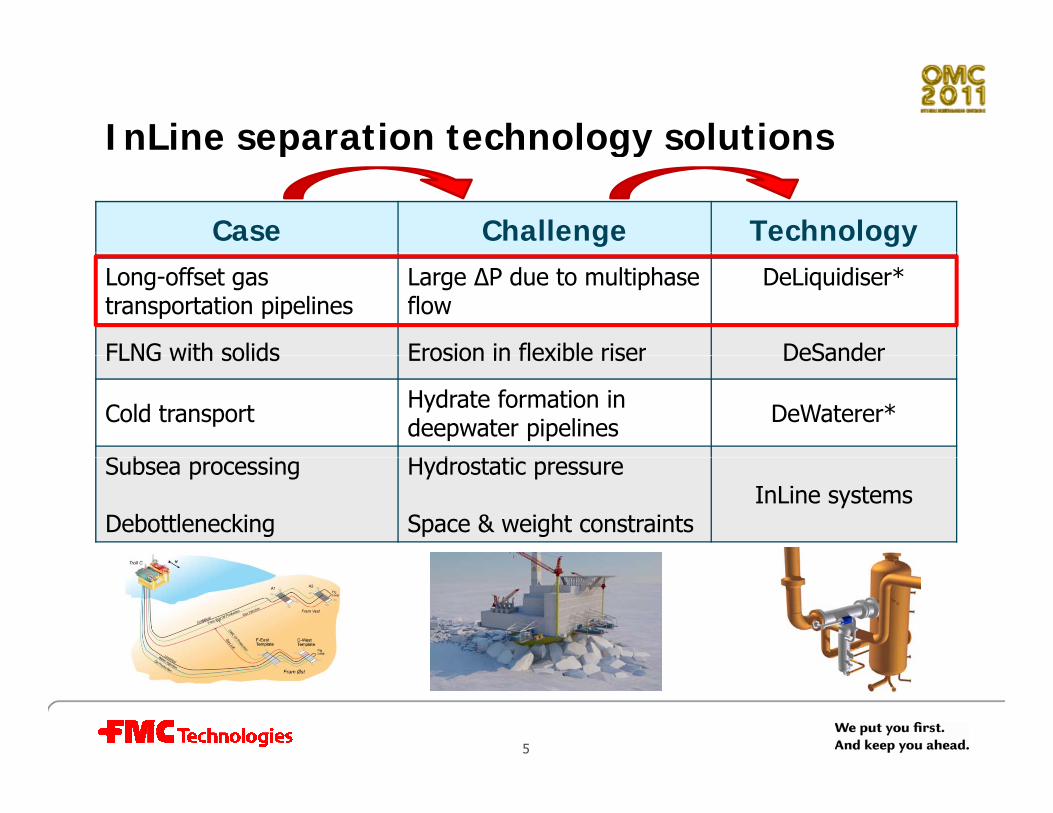
InLine separation technology solutionsp gy
Case Challenge TechnologyLong-offset gas transportation pipelines
Large ∆P due to multiphaseflow
DeLiquidiser*
FLNG with solids Erosion in flexible riser DeSanderFLNG with solids Erosion in flexible riser DeSander
Cold transport Hydrate formation indeepwater pipelines DeWaterer*
S b i H d t tiSubsea processing
Debottlenecking
Hydrostatic pressure
Space & weight constraintsInLine systems
5
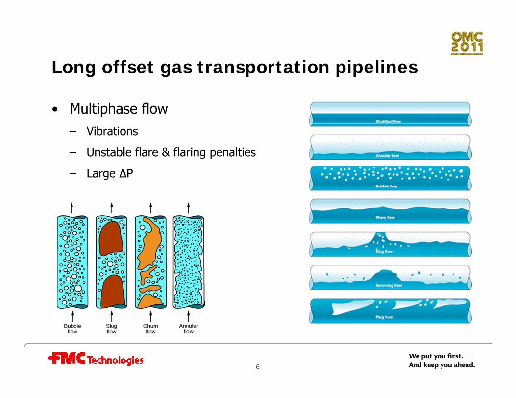
Long offset gas transportation pipelines g g p p p
• Multiphase flow– Vibrations
– Unstable flare & flaring penalties
– Large ∆P– Large ∆P
6

InLine gas liquid separation equipment fl i ivs. flow composition
InLine DeGasser InLine PhaseSplitter InLine DeLiquidiser100 %
100%
Liquid from gasGas from Liquid
80 %
60 %
40 %
100%
ffic
ienc
y
I i GVF t i l t
Set Point
Liquid from gas
90 92 94 96 98 100
Gas from Liquid20 %
0 %
10 20 30 40 50 60 70
90% 100% 0% 60% 20% 95%
0%
Ef
Increasing GVF at inlet
7
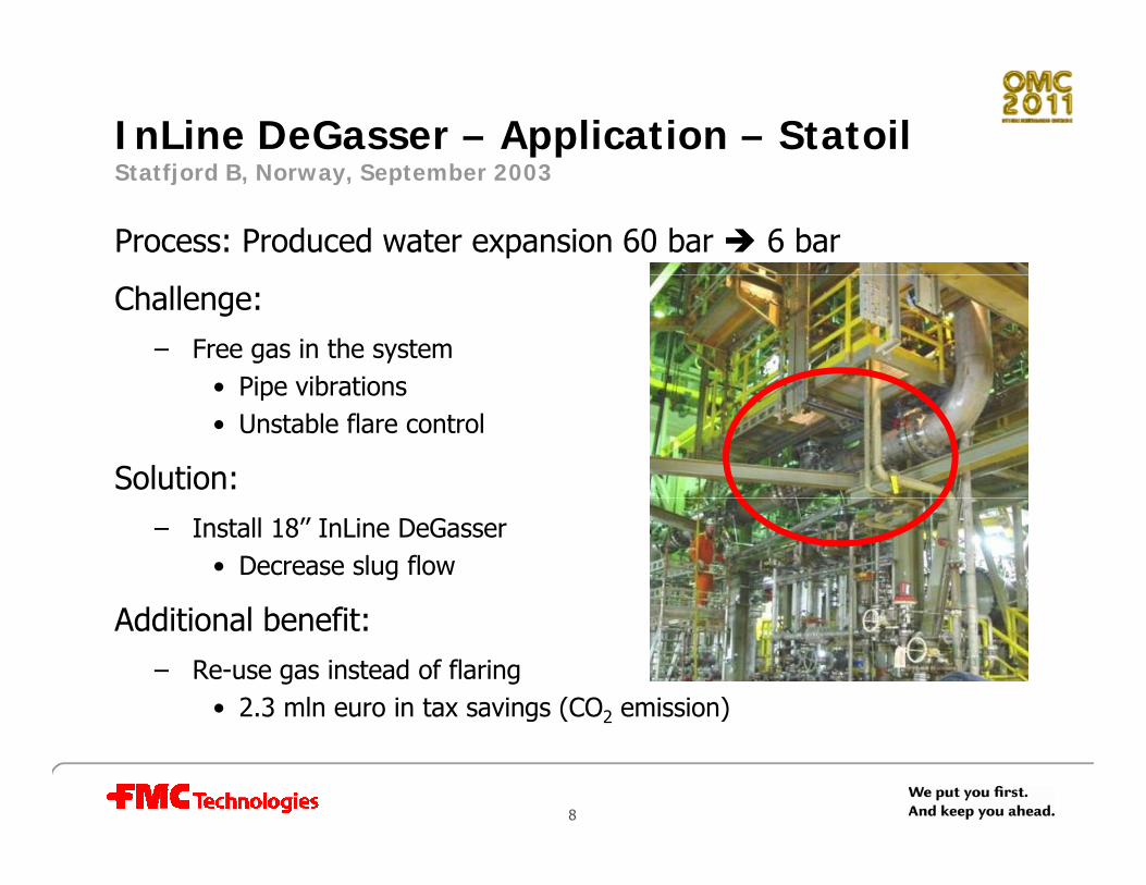
InLine DeGasser – Application – Statoil S fj d B N S b 2003Statfjord B, Norway, September 2003
Process: Produced water expansion 60 bar 6 bar
Challenge: – Free gas in the system
• Pipe vibrations• Pipe vibrations• Unstable flare control
Solution:– Install 18’’ InLine DeGasser
• Decrease slug flow
Additi l b fitAdditional benefit:– Re-use gas instead of flaring
• 2.3 mln euro in tax savings (CO2 emission)g 2
8

InLine PhaseSplitter – Application – Statoil V l f ikk N 2004Veslefrikk, Norway, 2004
VFA VFBOriginal setup VFA VFB
10 barg
Inlet separator
10 barg
Prod. header@16 barg
9

InLine PhaseSplitter – Application – Statoil V l f ikk N 2004Veslefrikk, Norway, 2004
• Production header pressure decrease 2 bar
• Corresponding increase in production
VFA VFBGas lines
After implementation
I l t t
10 bargInLine PhaseSplitter
Inlet separator
Prod. header@14 barg
Liquid lines
10
@14 barg

InLine Deliquidiser – Application – BP ETAP U i d Ki d M 2003ETAP, United Kingdom, May 2003
• Location: Upstream HP gas cooler discharge drum
• Flow rates: 554 MMSCFD & 56.9 m3/h (water + HC) (62barg)
Before installation
• Condensate carry-over
After installationLxWxH = 4.1x0.5x4.3mWeight = 4208kg
• System availability 97% (from 26%)
• Water dew point export gas -52°C (from -20°C)
11

InLine separation technology solutionsp gy
Case Challenge TechnologyLong-offset gas transportation pipelines
Large ∆P due to multiphaseflow
DeLiquidiser*
FLNG with solids Erosion in flexible riser DeSanderFLNG with solids Erosion in flexible riser DeSander
Cold transport Hydrate formation indeepwater pipelines DeWaterer*
S b i H d t tiSubsea processing
Debottlenecking
Hydrostatic pressure
Space & weight constraintsInLine systems
12
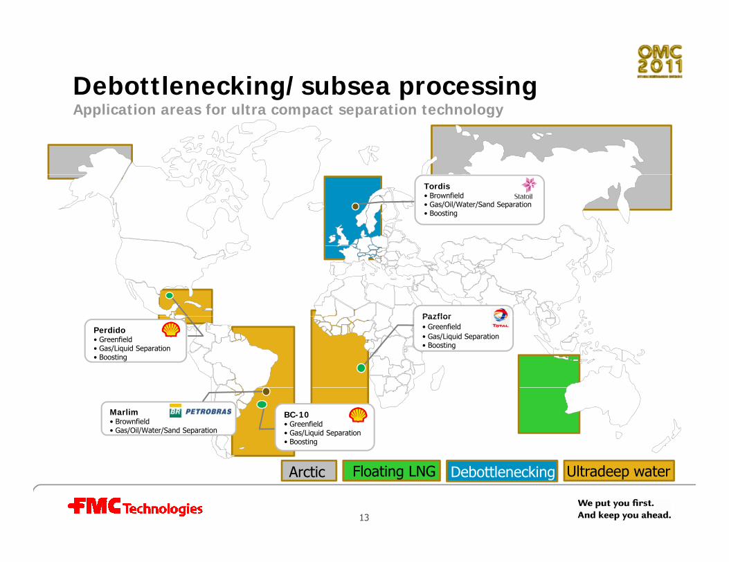
Debottlenecking/subsea processing A li i f l i h lApplication areas for ultra compact separation technology
Tordis• Brownfield• Gas/Oil/Water/Sand Separation• Boosting
Pazflor
Perdido• Greenfield• Gas/Liquid Separation• Boosting
Pazflor• Greenfield• Gas/Liquid Separation• Boosting
Marlim• Brownfield• Gas/Oil/Water/Sand Separation
BC-10• Greenfield• Gas/Liquid Separation• Boosting
13
Debottlenecking Ultradeep waterFloating LNGArctic
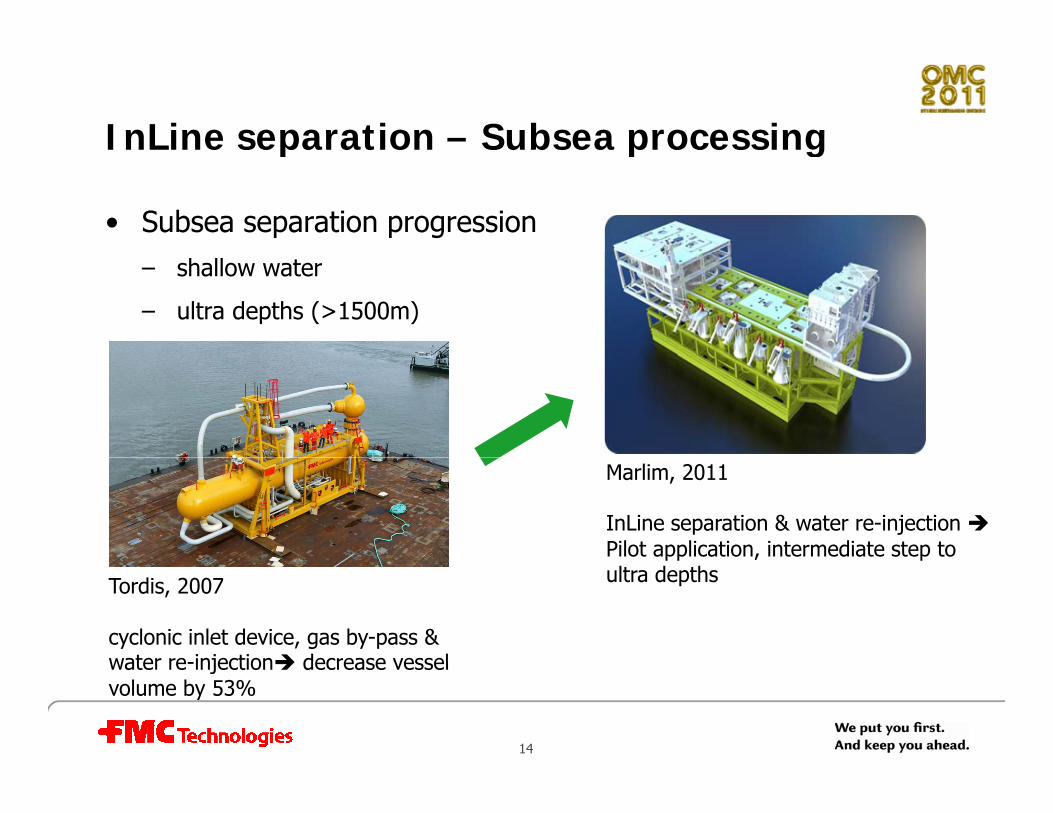
InLine separation – Subsea processingp p g
• Subsea separation progression– shallow water
– ultra depths (>1500m)
Marlim, 2011
InLine separation & water re-injection Pilot application, intermediate step to
Tordis, 2007
cyclonic inlet device, gas by-pass & water re-injection decrease vessel
pp pultra depths
14
water re-injection decrease vessel volume by 53%

Subsea InLine separation skid – MarlimB il d 2011
• Sand is recombined with oil & gas and produced to surface
Brazil, start up expected 2011
• Water is re-injected
• Separation components – Inlet InLine DeSander
– Gas harp
PipeSeparator– PipeSeparator
– Outlet section
– InLine water DeSander
– InLine HydroCycloneInstalled @ 900 m
API 21 25°API ~ 21 - 25°
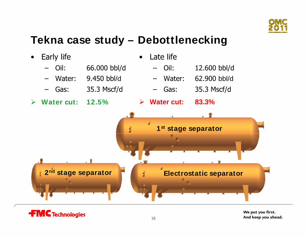
Tekna case study – Debottleneckingy g• Early life
– Oil: 66.000 bbl/d
• Late life– Oil: 12.600 bbl/d
– Water: 9.450 bbl/d– Gas: 35.3 Mscf/d
Water cut: 12.5%
– Water: 62.900 bbl/d– Gas: 35.3 Mscf/d
Water cut: 83.3%Water cut: 12.5% Water cut: 83.3%
1st stage separator
2nd stage separator Electrostatic separator
16

Tekna case study – Debottleneckingy g• Early life
– Oil: 66.000 bbl/d
• Late life– Oil: 12.600 bbl/d
– Water: 9.450 bbl/d– Gas: 35.3 Mscf/d
Water cut: 12.5%
– Water: 62.900 bbl/d– Gas: 35.3 Mscf/d
Water cut: 83.3%
MPMInLine DeGasser
Water cut: 12.5% Water cut: 83.3%
InLine PhaseSplitter2 x 10”
2 x 6”
InLine ElectroCoalescer8” & 6”
InLine DeWaterer21 & 10 liners
17
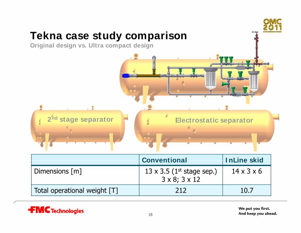
Tekna case study comparison O i i l d i Ul d i
1st stage separator
Original design vs. Ultra compact design
1 stage separator
Electrostatic separatorElectrostatic separator2nd stage separator2nd stage separator
Conventional InLine skidConventional InLine skid
Dimensions [m] 13 x 3.5 (1st stage sep.)3 x 8; 3 x 12
14 x 3 x 6
Total operational weight [T] 212 10 7
18
Total operational weight [T] 212 10.7

Pushing the oil recovery factor How can ultra compact separation solutions help?
Market trends Ultra compact solutionsMarket trends• Increase production
• Extend field life time
Ultra compact solutions• Debottleneck separation capacity
• Decrease pressure drop
• Reduce OPEX
p p
• Reduce costs– Maintenance
– Inspection
– Boosting
– Heating
• HSE
g
• Reduce inventory
19

We put you First, and keep you Ahead
20
www.fmctechnologies.com/separation