Pursuant to section 12 of the Weights and Measures Act ...
12
3030 V(6)g Issue Date: Valid Until: 22 January 2019 14 September 2025 Grégory Glas Lead Technical Manager For and on behalf of the Head of Technical Services NMO I Stanton Avenue I Teddington I TW11 OJZ I United Kingdom Tel +44 (0) 20 8943 7272 I Fax +44 (0) 20 8943 7270 I Web www.gov.uk/government/organisations/office-for-product-safety-and-standards NMO is part of the Office for Product Safety and Standards within the Department for Business, Energy & Industrial Strategy Pursuant to section 12 of the Weights and Measures Act 1985 Certificate No 3030 Revision 1 Issued by: NMO In accordance with the provisions of section 12 of the Weights and Measures Act 1985, the Secretary of State for Business, Innovation & Skills has issued this UK national type-approval certificate to: Axle Weight Technology Limited Axtec House Picow Farm Road Runcorn WA7 4UN United Kingdom And hereby certifies as suitable for use for trade the following pattern of an automatic road-weighbridge for measuring the gross weight of road vehicles in-motion, and designated the Axtec 5000. The necessary data (principal characteristics, alterations, securing, functioning etc) for identification purposes and conditions (when applicable) are set out in the descriptive annex to this certificate. Under the provisions of section 12(5) of the said Act, this certificate is subject to the conditions described in the descriptive annex. Note: This certificate relates to the suitability of the equipment for use for trade only in respect of its metrological characteristics. It does not constitute or imply any guarantee as to the safety of the equipment in use for trade or otherwise. This revision replaces previous versions of the certificate.
Transcript of Pursuant to section 12 of the Weights and Measures Act ...

3030
V(6)g
Issue Date: Valid Until:
22 January 2019 14 September 2025
Grégory Glas Lead Technical Manager For and on behalf of the Head of Technical Services
NMO I Stanton Avenue I Teddington I TW11 OJZ I United Kingdom Tel +44 (0) 20 8943 7272 I Fax +44 (0) 20 8943 7270 I Web www.gov.uk/government/organisations/office-for-product-safety-and-standards
NMO is part of the Office for Product Safety and Standards within the Department for Business, Energy & Industrial Strategy
Pursuant to section 12 of the Weights and Measures Act 1985
Certificate No 3030 Revision 1
Issued by:
NMO
In accordance with the provisions of section 12 of the Weights and Measures Act 1985, the Secretary of State for Business, Innovation & Skills has issued this UK national type-approval certificate to:
Axle Weight Technology Limited Axtec House Picow Farm Road Runcorn WA7 4UN United Kingdom
And hereby certifies as suitable for use for trade the following pattern of an automatic road-weighbridge for measuring the gross weight of road vehicles in-motion, and designated the Axtec 5000.
The necessary data (principal characteristics, alterations, securing, functioning etc) for identification purposes and conditions (when applicable) are set out in the descriptive annex to this certificate.
Under the provisions of section 12(5) of the said Act, this certificate is subject to the conditions described in the descriptive annex.
Note: This certificate relates to the suitability of the equipment for use for trade only in respect of its metrological characteristics. It does not constitute or imply any guarantee as to the safety of the equipment in use for trade or otherwise.
This revision replaces previous versions of the certificate.

2
CONTENTS CERTIFICATION No 3030 1 INTRODUCTION 2 CONSTRUCTION 3 INSTRUMENT SPECIFICATIONS 4 LEGENDS AND MARKINGS 5 SEALING MEASURES 6 PERIPHERALS AND INTERFACES 7 OPERATION 8 CONDITIONS 9 AUTHORISED ALTERNATIVES 10 CERTIFICATE HISTORY
ILLUSTRATIONS Figure 1 Schematic diagram Figure 2 Axtec 5000 indicator and tamper evident sealing sticker Figure 3 Typical ticket printout Figure 4 Information to be printed on the tamper-evident self-adhesive sticker Figure 5 Software identification and counter value

3
CERTIFICATION NO 3030
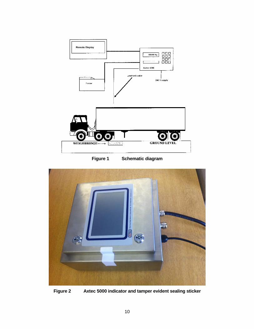
Descriptive Annex 1 INTRODUCTION This pattern of an automatic (in-motion) road weighbridge comprises an Axtec 5000 weight indicator and a weighbridge, supported by four load cells, having level approaches on both sides. The system determines the total weight of road vehicles (having a maximum of 7 axles), in a single or dual direction of travel. The system has a maximum capacity of 15 000 kg, a minimum capacity of 250 kg and a minimum scale interval (d) of 5 kg. A printer and a remote display may be connected. A schematic diagram is shown in Figure 1.
2 CONSTRUCTION 2.1 Mechanical 2.1.1 Weigh zone The weigh zone comprises one load receptor with aprons on both sides. 2.1.2 Load receptor The load receptor, comprising a flush mounted weigh platform fitted with four load cells, is situated within a pit. Drainage is provided within the pit to ensure that no portion of the instrument becomes submerged or partially submerged in water or any other liquid. 2.1.3 Aprons Aprons, constructed of reinforced concrete, extend in advance of and beyond the load receptor to a length sufficient (minimum 3 metres) to provide the road surface characteristics needed to achieve the required level of accuracy for weighing the desired types of vehicles in motion. A line or marker is used to indicate the start of the approach apron. 2.1.4 Vehicle guide device Traffic Management (for instance barriers, kerbing, signage or traffic lights) shall be put in place to ensure the axles pass completely over the platform.
2.2 Electrical/electronic 2.2.1 Weight indicator The Axtec 5000 digital indicator (Figure 2) has the following features:
Stainless steel enclosure
Hinged door
Touchscreen display
4 weighing channels
4
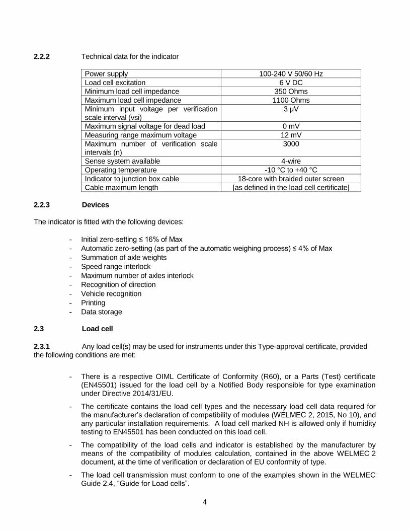
2.2.2 Technical data for the indicator
Power supply 100-240 V 50/60 Hz
Load cell excitation 6 V DC
Minimum load cell impedance 350 Ohms
Maximum load cell impedance 1100 Ohms
Minimum input voltage per verification scale interval (vsi)
3 μV
Maximum signal voltage for dead load 0 mV
Measuring range maximum voltage 12 mV
Maximum number of verification scale intervals (n)
3000
Sense system available 4-wire
Operating temperature -10 °C to +40 °C
Indicator to junction box cable 18-core with braided outer screen
Cable maximum length [as defined in the load cell certificate]
2.2.3 Devices The indicator is fitted with the following devices:
Initial zero-setting ≤ 16% of Max
Automatic zero-setting (as part of the automatic weighing process) ≤ 4% of Max
Summation of axle weights
Speed range interlock
Maximum number of axles interlock
Recognition of direction
Vehicle recognition
Printing
Data storage 2.3 Load cell
2.3.1 Any load cell(s) may be used for instruments under this Type-approval certificate, provided the following conditions are met:
There is a respective OIML Certificate of Conformity (R60), or a Parts (Test) certificate (EN45501) issued for the load cell by a Notified Body responsible for type examination under Directive 2014/31/EU.
The certificate contains the load cell types and the necessary load cell data required for the manufacturer’s declaration of compatibility of modules (WELMEC 2, 2015, No 10), and any particular installation requirements. A load cell marked NH is allowed only if humidity testing to EN45501 has been conducted on this load cell.
The compatibility of the load cells and indicator is established by the manufacturer by means of the compatibility of modules calculation, contained in the above WELMEC 2 document, at the time of verification or declaration of EU conformity of type.
The load cell transmission must conform to one of the examples shown in the WELMEC Guide 2.4, “Guide for Load cells”.
5
2.4 Printer 2.4.1 Any simple recipient printer may be used if:
it bears the CE marking for conformity to the EMC Directive;
it is not capable of transmitting any data or instruction into the indicator other than to release a printout, checking for correct data transmission;
it prints weighing results and other data as received from the indicator without any modification or further processing; and
it complies with the applicable requirements of EN45501, i.e. 4.2, 4.4, 4.6 and 4.7.
The printer is connected to the indicator via a protected interface. Upon completion of a weighing cycle, information is sent from the indicator via a serial link to the printer. An example printout is shown in Figure 3. The printout shall include at least the following information:
Total vehicle mass with unit
Date and time
Operating speed or warning message if applicable
“TOTAL WEIGHT ONLY MAY BE USED FOR TRADE PURPOSES” or similar wording if these weight values are printed
2.4.2 The measurement data may be automatically stored on the indicator as an alternative, and shall include the information listed in section 2.4.1. 2.5 Remote display
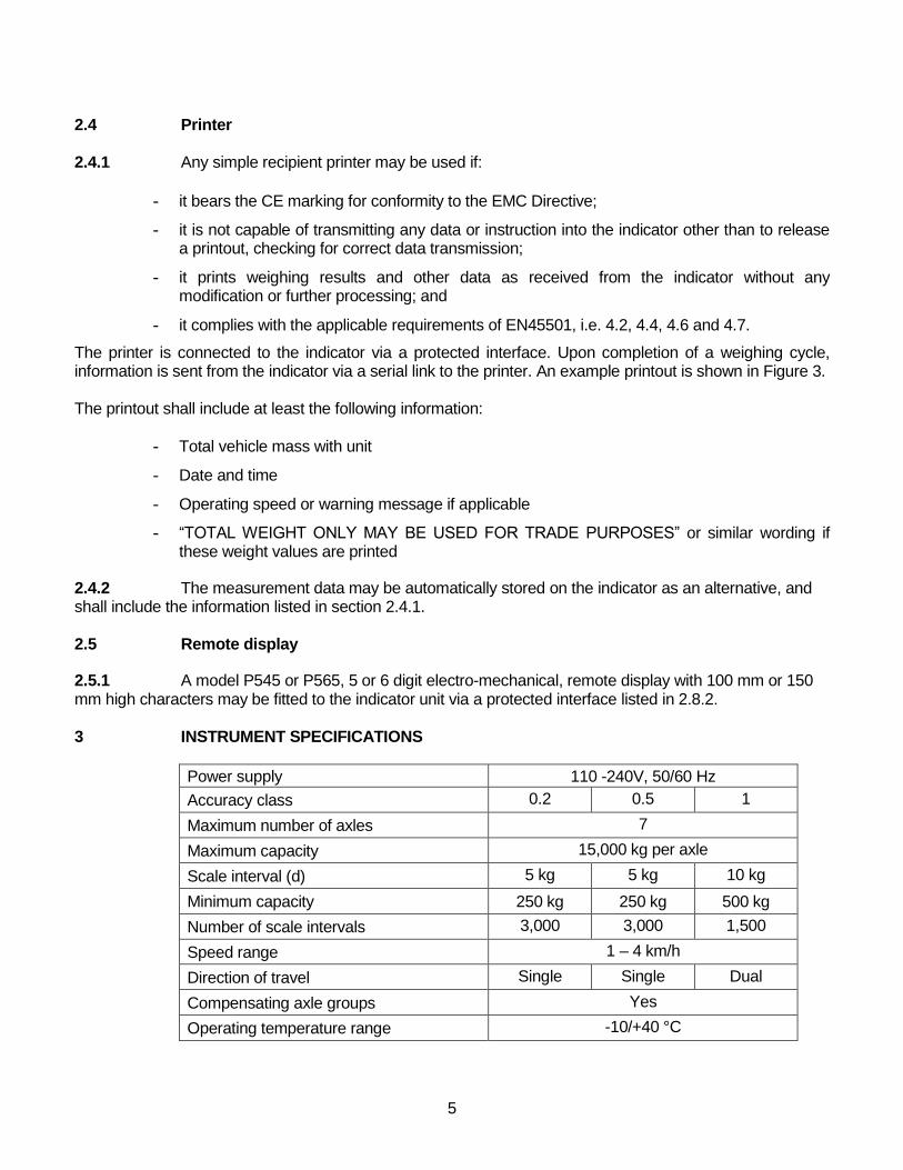
2.5.1 A model P545 or P565, 5 or 6 digit electro-mechanical, remote display with 100 mm or 150 mm high characters may be fitted to the indicator unit via a protected interface listed in 2.8.2. 3 INSTRUMENT SPECIFICATIONS
Power supply 110 -240V, 50/60 Hz
Accuracy class 0.2 0.5 1
Maximum number of axles 7
Maximum capacity 15,000 kg per axle
Scale interval (d) 5 kg 5 kg 10 kg
Minimum capacity 250 kg 250 kg 500 kg
Number of scale intervals 3,000 3,000 1,500
Speed range 1 – 4 km/h
Direction of travel Single Single Dual
Compensating axle groups Yes
Operating temperature range -10/+40 °C
6
4 LEGENDS AND MARKINGS 4.1 The manufacturer’s name is located on the front cover of the indicating device. The following inscriptions are on a data plate which cannot be removed without being destroyed:
Manufacturer Designation Certificate number Accuracy Class Serial number Minimum capacity (Min) Maximum capacity (Max) Operating speed range Maximum number of axles Scale interval (d) Direction of weighing
4.2 The following information may also be on the data plate
Axle Weight Technology Ltd Axtec House, Picow Farm Road, Runcorn WA7 4UN Tel: 01928 581575 Email: [email protected]
5 SEALING MEASURES 5.1 Hardware Access to the hardwired load cell connection, electronics and software download connection is prevented by sealing the enclosure via a wire and seal solution or tamper-evident sticker. Figure 2 shows an example of the sealing method. Figure 4 shows the information to be printed on the tamper-evident self-adhesive sticker, which may also be accompanied by the information in section 4.1. The junction box shall be sealed via a wire and seal solution or tamper-evident sticker 5.2 Software The software identification shall be as follows, with xx, and x, reflecting minor, non-legally relevant modifications. The identification is shown at power up: VERSION DynV1_xx CPU 2 uP2_V1_x Download of software requires access to the PCB, and as such is prevented by the hardware sealing described in section 5.1. Access to the legally relevant parameters is password-protected. A non-editable counter increments when a legally relevant parameter is changed. The counter is designated Verification Counter and is displayed on power up. The value of the counter must be written on a tamper-evident label on or near the rating plate.
Figure 5 shows the software identification and counter value.
7
6 PERIPHERALS AND INTERFACES 6.1 Peripherals 6.1.1 The weighing system may be connected to any peripheral which is technically compatible; has been issued with Parts (Test) Certificate by a Notified Body responsible for Module B under Directives 2014/31/EU or 2014/32/EU and bears the CE marking of conformity to the relevant directives, via an interface listed in Section 6.2.1.
6.1.2 An Axtec automatic identification system may be connected to the system via an interface listed in Section 6.2.1. A radio transponder, fitted to the vehicle, sends a unique vehicle identification code to the automatic identification system, which is then transmitted to the Axtec 5000 weight indicator. The code contains vehicle identification information only. 6.2 Interfaces 6.2.1 The instrument may be fitted with the following protected interfaces:
− 4-wire load cell connection
− 4 x RS232C
− 4 x 20 mA
− 4 x 5 V contact closure inputs/outputs
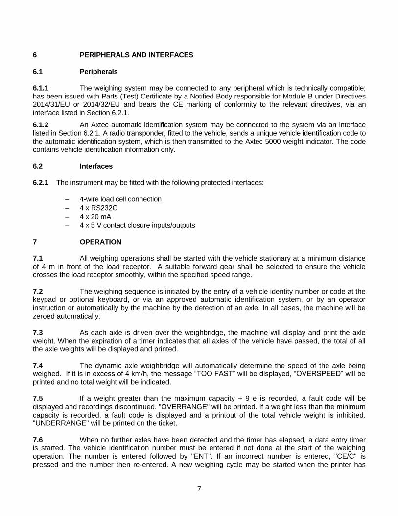
7 OPERATION 7.1 All weighing operations shall be started with the vehicle stationary at a minimum distance of 4 m in front of the load receptor. A suitable forward gear shall be selected to ensure the vehicle crosses the load receptor smoothly, within the specified speed range. 7.2 The weighing sequence is initiated by the entry of a vehicle identity number or code at the keypad or optional keyboard, or via an approved automatic identification system, or by an operator instruction or automatically by the machine by the detection of an axle. In all cases, the machine will be zeroed automatically. 7.3 As each axle is driven over the weighbridge, the machine will display and print the axle weight. When the expiration of a timer indicates that all axles of the vehicle have passed, the total of all the axle weights will be displayed and printed. 7.4 The dynamic axle weighbridge will automatically determine the speed of the axle being weighed. If it is in excess of 4 km/h, the message “TOO FAST” will be displayed, “OVERSPEED” will be printed and no total weight will be indicated. 7.5 If a weight greater than the maximum capacity + 9 e is recorded, a fault code will be displayed and recordings discontinued. "OVERRANGE" will be printed. If a weight less than the minimum capacity is recorded, a fault code is displayed and a printout of the total vehicle weight is inhibited. "UNDERRANGE" will be printed on the ticket. 7.6 When no further axles have been detected and the timer has elapsed, a data entry timer is started. The vehicle identification number must be entered if not done at the start of the weighing operation. The number is entered followed by "ENT". If an incorrect number is entered, "CE/C" is pressed and the number then re-entered. A new weighing cycle may be started when the printer has
8
printed the ticket. Failure to enter the vehicle identification number within a specified time will automatically complete the weigh cycle and the vehicle identification number will be printed as "NONE". 8 CONDITIONS
8.1 Only the totalised gross vehicle weight may be used for trade purposes.
9 AUTHORISED ALTERNATIVES 9.1 The indicator may be used to transmit data from the weighing system to a computer, connected to a protective interface, and associated ticket printer. The computer may incorporate a monitor and associated keyboard. 9.1.1 A unique consecutive number shall be automatically generated by the indicator associated with each weight sent to the computer. Unique in this context means that it shall not be repeated within one year. The consecutive number, including where relevant the date, shall not be capable of readily being reset. 9.1.2 Data sent from the computer or associated keyboard to the indicator shall not allow the metrological functions of the indicator and its measurement data to be inadmissibly influenced. 9.1.3 Any weight related data produced by, or from a printer, connected to the computer shall carry a clear statement, "A tally-roll record of this weight is retained for 90 days and may be found by reference to the unique consecutive number", or appropriate equivalent wording which shall be clear and unambiguous 9.1.4 Where a stored "weighed tare or first weight" is used then the consecutive number of that weight and the date of weighment must be shown on the relevant documents. Stored weighed tares shall be checked regularly. 9.1.5 Disconnection of the tally-roll power supply, data line or shortage of paper shall inhibit data transmission to the computer. 9.1.6 The computer shall not be used to control functions affecting the operation of the weighing system e.g., zero setting devices, barriers to control the position of a vehicle on a weighbridge etc. 9.2 Having a static mode of operation, accessible by a secure password which is used for calibration and test purposes only.
9
10 CERTIFICATE HISTORY
ISSUE NO. DATE DESCRIPTION
Certificate No 3030 15 September 2015 Certificate first issued.
Certificate No 3030 Revision 1
22 January 2019 Updated references from 2009/23/EC to 2014/31/EU.
Corrected VSI in Section 2.2.2.
Amended instrument specifications throughout certificate from:
Accuracy class 1
Scale interval (d) 10 kg
Minimum capacity 500 kg
Number of scale intervals
1500
Direction of travel Single
Removed section 8.2 (instrument now suitable for both directions of travel).
10
Figure 1 Schematic diagram
Figure 2 Axtec 5000 indicator and tamper evident sealing sticker

11
Figure 3 Typical ticket printout
Axle Weight Technology Ltd Axtec House, Picow Farm Road, Runcorn WA7 4UN Tel: 01928 581575 Email: [email protected]
Figure 4 Information to be on the tamper-evident self-adhesive sticker

12
Figure 5 Software identification and counter value
© Crown copyright 2018 NMO Office for Product Safety and Standards Department for Business, Energy & Industrial Strategy This material may be freely reproduced except for sale