PuraLev 4000MU - Levitronix
42
User Manual for PuraLev ® 4000MU www.levitronix.com PL-4045-00, Rev01, DCO# 20-144 First Release: 02-Aug-14 Last Update: 09-Jul-2020 PuraLev ® 4000MU 4.6 bar (67 psi) 200 liters/min (53 gallons/min) USER MANUAL This manual contains information necessary for the safe and proper use of the PuraLev ® 4000MU. Included are specifications for the standard configurations of the pump system and instructions regarding its use, installation, operation, adjustment, inspection and maintenance. For special configurations of the pump system refer to accompanying information. If the system must be configured for other parameter settings, then the Levitronix ® Service Software version V2.0.5.0 or higher (with according manual Levitronix Doc.# PL-4046-00) is necessary. Familiarize yourself with the contents of the manual to ensure the safe and effective use of this product. After reading this manual, please store the manual where the personnel responsible for operating the pump system can readily refer to it at any time.
Transcript of PuraLev 4000MU - Levitronix
User Manual for PuraLev® 4000MU www.levitronix.com
PL-4045-00, Rev01, DCO# 20-144 First Release: 02-Aug-14 Last Update: 09-Jul-2020
PuraLev® 4000MU 4.6 bar (67 psi) 200 liters/min (53 gallons/min)
USER MANUAL
This manual contains information necessary for the safe and proper use of the PuraLev® 4000MU. Included are specifications for the standard configurations of the pump system and instructions regarding its use, installation, operation, adjustment, inspection and maintenance. For special configurations of the pump system refer to accompanying information. If the system must be configured for other parameter settings, then the Levitronix® Service
Software version V2.0.5.0 or higher (with according manual Levitronix Doc.# PL-4046-00) is necessary. Familiarize yourself with the contents of the manual to ensure the safe and effective use of this product. After reading this manual, please store the manual where the personnel responsible for operating the pump system can readily refer to it at any time.

User Manual for PuraLev® 4000MU www.levitronix.com
PL-4045-00, Rev01, DCO# 20-144 2
Table of Content
1 SAFETY PRECAUTIONS ............................................................................................................................................................... 3
2 SPECIFICATIONS .......................................................................................................................................................................... 4 2.1 Specification of Components ................................................................................................................................................. 4 2.2 Standard System Configurations ........................................................................................................................................... 6 2.3 Pressure-Flow Curves ........................................................................................................................................................... 8 2.4 NPSHr .................................................................................................................................................................................. 8 2.5 Maximum Static Pressure of Pump Head .............................................................................................................................. 9 2.6 General Environmental Conditions ........................................................................................................................................ 9 2.7 Basic Dimensions of Main Components .............................................................................................................................. 10
3 ENGINEERING INFORMATION ................................................................................................................................................... 13 3.1 Sealing and Material Concept ............................................................................................................................................. 13 3.2 AC Supply and Power Consumption ................................................................................................................................... 14 3.3 Temperature Monitoring ...................................................................................................................................................... 15 3.4 Thermal Management ......................................................................................................................................................... 16 3.5 Hydraulic Circuit Design ...................................................................................................................................................... 19
4 INSTALLATION ........................................................................................................................................................................... 20 4.1 Electrical Installation of Controller ....................................................................................................................................... 20 4.2 Mechanical Installation of the Pump/Motor .......................................................................................................................... 26 4.3 Mechanical Installation of the Controller .............................................................................................................................. 28 4.4 Mechanical Installation of Adaptor/Extension Cables .......................................................................................................... 28
5 OPERATION ................................................................................................................................................................................ 29 5.1 System Operation with LPC-4000.1-05 (Standalone Version) ............................................................................................. 29 5.2 System Operation with Controller LPC-4000.2-05 (PLC Version) ........................................................................................ 32 5.3 System Operation for ATEX/IECEx and Cl1 Div2 Applications ............................................................................................ 34
6 INSTRUCTIONS FOR USE OF PUMP HEAD .............................................................................................................................. 35 6.1 Description and Preparation ................................................................................................................................................ 35 6.2 General Warnings and Cautions ......................................................................................................................................... 35 6.3 Replacement of Pump Head ............................................................................................................................................... 35 6.4 Assembling of Pump Head .................................................................................................................................................. 37 6.5 Assembly into a Circuit ........................................................................................................................................................ 37 6.6 Maintenance ....................................................................................................................................................................... 37
7 TROUBLESHOOTING ................................................................................................................................................................. 38 7.1 Troubleshooting for Operation with Controller LPC-4000.1-05 ............................................................................................. 38 7.2 Troubleshooting for Operation with Controller LPC-4000.2-05 ............................................................................................. 38 7.3 Troubleshooting with Levitronix® Service Software .............................................................................................................. 38
8 TECHNICAL SUPPORT ............................................................................................................................................................... 38
9 APPENDIX ................................................................................................................................................................................... 39 9.1 Regulatory Status ............................................................................................................................................................... 39 9.2 Symbols and Signal Words ................................................................................................................................................. 42
User Manual for PuraLev® 4000MU www.levitronix.com
PL-4045-00, Rev01, DCO# 20-144 3
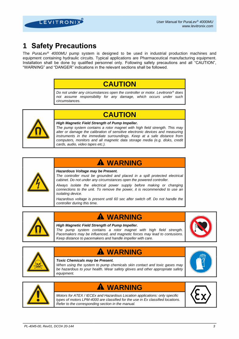
1 Safety Precautions The PuraLev® 4000MU pump system is designed to be used in industrial production machines and equipment containing hydraulic circuits. Typical applications are Pharmaceutical manufacturing equipment. Installation shall be done by qualified personnel only. Following safety precautions and all “CAUTION”, “WARNING” and “DANGER” indications in the relevant sections shall be followed.
CAUTION
Do not under any circumstances open the controller or motor. Levitronix® does not assume responsibility for any damage, which occurs under such circumstances.
CAUTION
High Magnetic Field Strength of Pump Impeller.
The pump system contains a rotor magnet with high field strength. This may alter or damage the calibration of sensitive electronic devices and measuring instruments in the immediate surroundings. Keep at a safe distance from computers, monitors and all magnetic data storage media (e.g. disks, credit cards, audio, video tapes etc.).
! WARNING
Hazardous Voltage may be Present.
The controller must be grounded and placed in a spill protected electrical cabinet. Do not under any circumstances open the powered controller.
Always isolate the electrical power supply before making or changing connections to the unit. To remove the power, it is recommended to use an isolating device.
Hazardous voltage is present until 60 sec after switch off. Do not handle the controller during this time.
! WARNING
High Magnetic Field Strength of Pump Impeller.
The pump system contains a rotor magnet with high field strength. Pacemakers may be influenced, and magnetic forces may lead to contusions. Keep distance to pacemakers and handle impeller with care.
! WARNING
Toxic Chemicals may be Present.
When using the system to pump chemicals skin contact and toxic gases may be hazardous to your health. Wear safety gloves and other appropriate safety equipment.
! WARNING
Motors for ATEX / IECEx and Hazardous Location applications: only specific types of motors LPM-4000 are classified for the use in Ex classified locations. Refer to the corresponding section in the manual.

User Manual for PuraLev® 4000MU www.levitronix.com
PL-4045-00, Rev01, DCO# 20-144 4
2 Specifications 2.1 Specification of Components Figure 1 shows the main system components (motor, controllers, and pump head) and Figure 2 illustrates the accessories.
Figure 1: Pump system with standard components
Figure 2: Pump system accessories
3a
3b
2d
8
C D
E
4a
4b
7
6a
B
5a 5b
2a
8
1
2b

User Manual for PuraLev® 4000MU www.levitronix.com
PL-4045-00, Rev01, DCO# 20-144 5
System Name Article # Pump-head Motor Controller Note
PuraLev-4000MU.1 PuraLev-4000MU.2
100-90822 100-90823
LPP-4000.3
LPM-4000.7 (ATEX) LPC-4000.1-05 LPC-4000.2-05
Adaptor/Extension (0.5 - 10m) cables according to Table 3 have to be ordered as separate article with specified length. ATEX Cable Sealing System can be ordered according to Table 4 (Position 9)
Certifications: CE, IECEE CB scheme, ETL (NRTL), ATEX and IECEx. PuraLev-4000MU.4 PuraLev-4000MU.5
100-90825 100-90826
LPM-4000.8 (ATEX) LPC-4000.1-05 LPC-4000.2-05
PuraLev-4000MU.7 PuraLev-4000MU.8
100-91191 100-91192
LPM-4000.11 (HazLoc) LPC-4000.1-05 LPC-4000.2-05
Adaptor/Extension (0.5 - 10m) cables according to Table 3 have to be ordered as separate article with specified length.
Certifications: CE, IECEE CB scheme, ETL (NRTL), ATEX and IECEx. PuraLev-4000MU.10 PuraLev-4000MU.11
100-91194 100-91195
LPM-4000.10 (HazLoc) LPC-4000.1-05 LPC-4000.2-05
Table 1: Standard system configurations
Pos. Component Article Name Article # Characteristics Value / Feature
1 Pump-Head LPP-4000.3 100-90821
Impeller Housing Top / Bottom Triclamp Sealing Ring Fittings
PFA (FDA, USP Class VI, BSE/TSE/animal free) Stainless Steel / PEEK (FDA, USP Class VI, BSE/TSE free) EPDM (FDA, USP Class VI, BSE/TSE/animal free)
DIN 11864-2, Type B, DN40 for inlet and DN25 for outlet
Max. Flow Max. Diff.-Pressure Max. Viscosity / Density
200 liters/min / 53 gallons/min 4.6 bar / 67 psi Aqueous liquids (others on request)
Max. Liquid Temp. Full performance: 70 0C / 158 0F Limited performance: 70-90 0C / 158-194 0F (see Figure 7)
Weight Wet Volume / Surface
5.5 kg / 12 lb
Sterilization Methods CIP and SIP
2a
2b Motor (ATEX certified)
LPM-4000.7
LPM-4000.8
100-10047
100-10048
Housing Cable / Connectors
Epoxy (a) or ETFE (b) coated Alu (IP67) 2x 3m cables with PVC (a) or FEP (b) jacket / 2x circular (IP67)
ATEX Marking II 3G Ex nA IIC T5 Gc / II 3D Ex tc IIIC T100°C Dc
Weight 35 kg / 77 lb
2b Motor (HazLoc)
LPM-4000.11
LPM-4000.10
100-10116
100-10115
Housing Connectors
Epoxy (a) or ETFE (b) coated Aluminum 2x circular (IP67 when connected)
HazLoc Marking Class I, Div2, Groups A-D T5 Class II, Div2, Groups E-G T5
3a
Standalone
Controller (User Panel)
LPC-4000.1-05
100-90820
(Supply and Enable connector included)
Voltage / Current 1 x 200-240 V AC 10% / 4 kW @ 50/60 Hz
3 x 200-240 V AC 10% / 4 kW @ 50/60 Hz
See Section 3.2 for details.
Electrical Power 4 kW
Housing Protection IP20
Weight 6.5 kg / 14.3 lb
Interfaces for Standalone Controller
Panel to set speed (automatic storage on internal EEPROM)
PLC with 1x analog input (“Speed”) 4 - 20 mA 1x digital input (“Enable”) 0 - 24 V (optocoupler) 1x digital output (“Status”) 0 - 24 V (relais)
Standard Firmware F2.25
3b Extended Controller (PLC and USB)
LPC-4000.2-05
100-90811
(Supply and PLC connector included)
Interfaces for Extended Controller
PLC with
- up to 4 digital inputs 0 - 24V (optocoupler) - up to 4 digital outputs 0 - 24 V (relais) - up to 2 analog inputs 4 - 20mA - up to 2 analog inputs 0 – 10 V - up to 2 analog outputs 0 – 5 V
USB interface (for service and system monitoring)
Standard Firmware F2.48
Table 2: Specification of standard components
Pos. Component Article Name Article #
Characteristics Value / Feature Sensor Cable Power Cable Sensor Power
4a
4b
Extension Adaptor Cable for Sensor (a) and Power (b) Wires
MCAS-600.2-05 (0.5m) MCAS-600.2-30 (3m) MCAS-600.2-50 (5m) MCAS-600.2-70 (7m) MCAS-600.2-100 (10m)
MCAP-4000.5-05 MCAP-4000.5-30 MCAP-4000.5-50 MCAP-4000.5-70 MCAP-4000.5-100
190-10226 190-10238 190-10127 190-10105 190-10239
190-10291 190-10292 190-10293 190-10294 190-10295
Jacket Material Connector Types Connector Material
PVC Circular wallmountable (IP-67) to D-SUB Metallic – Nickel coated
5a
5b
Interconnect Cable for Sensor (a) and Power (b) Wires
MCIS-2000.1-05 (0.5 m) MCIS-2000.1-30 (3 m) MCIS-2000.1-50 (5 m) MCIS-2000.1-70 (7 m) MCIS-2000.1-100 (10 m)
MCIP-4000.1-05 MCIP-4000.1-30 MCIP-4000.1-50 MCIP-4000.1-70 MCIP-4000.1-100
190-10391 190-10392 190-10393 190-10394 190-10395
190-10402 190-10403 190-10404 190-10405 190-10406
Jacket Material Connector Types Connector Material
PVC Circular M23 (IP67) to Circular M23 Metallic – Nickel coated
Table 3: Specification of adaptor/extension cables
Pos. Component Article Name Article # Characteristics Value / Feature
6a Air Cooling Module ACM-4000.1 190-10177 Material / Connection Port PP / NPT 1/2”
Air Pressure ~1 - 3 bar (14 – 43 psi)
6b Air Cooling Module ACM-4000.3 190-10190 Material PP-EL-S with conductive additive for operation with ATEX motor
7 Fan Cooling Module FCM-4000.1 190-10178 Housing Material Cable Supply Spec. / IP Rating
PP (+ 40% Talkum) PVC, 6m, open-end wires 20.4 – 27.6 VDC, 31.2 W, 1.3 A I IP-55
8 (A-F)
ATEX Cable Sealing System
ACS-A.1 (Roxtec)
100-90292 Sleeve (A) and Gasket (B) Frame (C) 2x Cable Module (D)
Stainless Steel and EPDM Roxylon (EPDM rubber) Roxylon (EPDM rubber)
Note: Lubricant (E) and measurement plates (F) are included.
9 Screw-Seal Set M16x16 PVDF/FKM 100-90913 Screw / Gasket Materials Torque Specification Purpose
M16 x 16 (SW24), PVDF / FKM 3 Nm Chemical protection of lifting eyebolt mounting thread of motor.
Table 4: Specification of accessories

User Manual for PuraLev® 4000MU www.levitronix.com
PL-4045-00, Rev01, DCO# 20-144 6
2.2 Standard System Configurations
2.2.1 Standalone System Configuration
The standalone configuration of the pump system (see Figure 3) consists of a controller with an integrated user panel to set the speed manually. The speed is automatically stored in the internal EEPROM of the controller. As an option, the speed can also be set with an analogue signal.
Figure 3: System configuration for standalone operation (Speed setting with integrated user panel)
2.2.2 Extended System Configuration
The extended version of the pump system (Figure 4) consists of a controller with an extended PLC interface.
This allows setting the speed by an external signal (see specification of Position 3b in Table 2) and enables
precise closed-loop flow or pressure control in connection with either a flow or a pressure sensor. A USB
interface allows communication with a PC in connection with the Levitronix® Service Software. Hence
parameterization, firmware updates and failure analysis are possible.
Figure 4: Extended operation (flow or pressure control) with extended controller
Controller
for
Standalone
Operation
Chemical Resistance and IP67 Space
Pump Head
Motor
Fluid In
Fluid Out
Motor Sensor Cable
Motor Power Cable
3 x AC 200-240V or
1 x AC 200-240V
Stand Alone
Operation
Speed Control
Adaptor/Extension
Cable for Sensors
Adaptor/Extension
Cable for Power
PLC Interface Speed Setting- 1x Digital Input (Enable)
- 1x Digital Output (Status)- 1x Analog Input (Speed)
Chemical Resistance
and IP67 Space
Controller
for
Extended
OperationPump Head
Motor
Fluid In
Fluid Out
Motor Sensor Cable
Motor Power Cable
USB- Service- Firmware Update
- Configuration etc.
Flow- orPressureSensor
Adaptor/Extension
Cable for Sensors
Adaptor/Extension
Cable for Power
Extended PLC Interface
Speed, Flow or Pressure Setting- 4 Digital INputs, 4 Digital Outputs
- 4 Analog Inputs, 2 Analog Outputs
3 x AC 200-240 V or
1 x AC 200-240V
2
3a
1
4a
4b
3b
2
1
4b
4a

User Manual for PuraLev® 4000MU www.levitronix.com
PL-4045-00, Rev01, DCO# 20-144 7
2.2.3 ATEX System Configuration
Together with the standard pump-head and controllers an ATEX certified motor allows installation of motor and pump-head within an ATEX Zone 2 area (see Figure 5). The ATEX motor (Pos. 2b in Table 2) comes delivered with special connectors and according extension cables (Pos. 5a and 5b in Table 4). One option to lead the cables outside of the ATEX area is an ATEX certified cable sealing system as listed in Table 4 (see Pos. 9) and shown in Figure 2.
Figure 5: System configuration for ATEX applications
2.2.4 Hazardous Location Cl1 Div2 System Configuration
Together with the standard pump head and controllers a Class1 Div2 certified motor allows installation of motor and pump head in a hazardous classified area (see Figure 6). The Cl1 Div2 motor (Pos. 2c and 2d in Table 2) comes with provisions for conduits which will lead the extension cables outside of the classified area.
Figure 6: System configuration for Cl1 Div2 applications
Motor
(ATEX)
Fluid In
Fluid Out
Motor Sensor Cable
Motor Power Cable
Adaptor/Extension
Cable for Sensors
Adaptor/Extension
Cable for Power
All
Controller
Types
ATEX conform cable sealing system
Cabinet Boundary for
ATEX Zone 2 Area
ATEX Zone 2 Classified Location
Chemical Resistance and IP-67 Space
3 x AC 200-240V or
1 x AC 200-240V
Pump Head
Motor
(HazLoc)
Fluid In
Fluid Out
Adaptor/Extension
Cable for Sensors
Adaptor/Extension
Cable for Power
All
Controller
Types
Cabinet Boundary for
Hazardous Location
Class I, Div 2
Hazardous Classified Location
Chemical Resistance and IP-67 Space
3 x AC 200-240V or
1 x AC 200-240V
Pump HeadNPT Threads
for Conduit
Conduit for Cables
Interconnect
Cable for Power
Interconnect
Cable for Sensor
1
2a 7
4a
4b
3
1
2c
6a
6b
3
5a
5b
2d
2b
User Manual for PuraLev® 4000MU www.levitronix.com
PL-4045-00, Rev01, DCO# 20-144 8
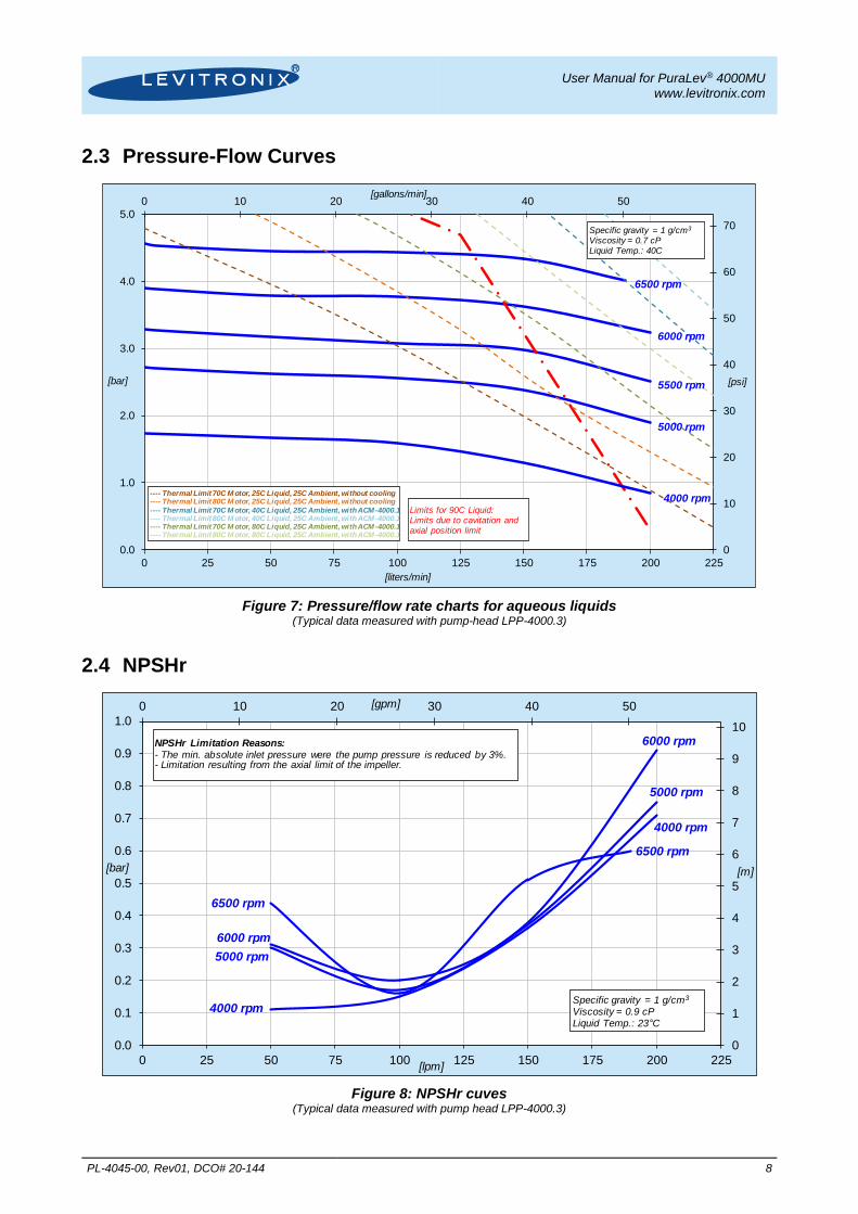
2.3 Pressure-Flow Curves
Figure 7: Pressure/flow rate charts for aqueous liquids
(Typical data measured with pump-head LPP-4000.3)
2.4 NPSHr
Figure 8: NPSHr cuves
(Typical data measured with pump head LPP-4000.3)
0
10
20
30
40
50
60
70
0 10 20 30 40 50
0.0
1.0
2.0
3.0
4.0
5.0
0 25 50 75 100 125 150 175 200 225
[psi]
[gallons/min]
[bar]
[liters/min]
Specific gravity = 1 g/cm3
Viscosity = 0.7 cPLiquid Temp.: 40C
6500 rpm
6000 rpm
5000 rpm
Limits for 90C Liquid:Limits due to cavitation and axial position limit
4000 rpm
5500 rpm
---- Thermal Limit 70C M otor, 25C Liquid, 25C Ambient, without cooling---- Thermal Limit 80C M otor, 25C Liquid, 25C Ambient, without cooling
---- Thermal Limit 70C M otor, 40C Liquid, 25C Ambient, with ACM-4000.1---- Thermal Limit 80C M otor, 40C Liquid, 25C Ambient, with ACM-4000.1---- Thermal Limit 70C M otor, 80C Liquid, 25C Ambient, with ACM-4000.1---- Thermal Limit 80C M otor, 80C Liquid, 25C Ambient, with ACM-4000.1
0
1
2
3
4
5
6
7
8
9
10
0 10 20 30 40 50
0.0
0.1
0.2
0.3
0.4
0.5
0.6
0.7
0.8
0.9
1.0
0 25 50 75 100 125 150 175 200 225
[m]
[gpm]
[bar]
[lpm]
NPSHr Limitation Reasons:- The min. absolute inlet pressure were the pump pressure is reduced by 3%.- Limitation resulting from the axial limit of the impeller.
6000 rpm
4000 rpm
5000 rpm
6500 rpm
4000 rpm
5000 rpm
6000 rpm
6500 rpm
Specific gravity = 1 g/cm3
Viscosity = 0.9 cPLiquid Temp.: 23 C

User Manual for PuraLev® 4000MU www.levitronix.com
PL-4045-00, Rev01, DCO# 20-144 9
2.5 Maximum Static Pressure of Pump Head
Figure 9: Max. pressure specifications of LPP-4000.3 pump head
2.6 General Environmental Conditions
Usage Indoor 1
Altitude Up to 2000 m
Operating ambient temperature 0 to 40°C
Storage ambient temperature (Extremes for Transportation)
-20 to 80°C
Operating humidity range (relative humidity) 15 – 95% (non-condensing)
Storage humidity range (relative humidity) (Extremes for Transportation)
15 – 95% (non-condensing)
Normal storage conditions Ambient temp.: 20 to 30°C Relative humidity: 50% (non-condensing)
AC supply fluctuations 10% of nominal voltage
Transient over-voltages typically present on the mains supply
Surge immunity according to EN 61000-4-5
Pollution degree 2
Table 5: Environmental conditions for pump system Note 1: Contact Levitronix® technical department (see Section 8) for outdoor usage.
0
50
100
150
200
77 87 97 107 117 127 137 147 157 167 177 187
0
2
4
6
8
10
12
14
16
25 30 35 40 45 50 55 60 65 70 75 80 85 90
[psi]
[°F]
[bar]
Liquid Temperature in [°C]
Maximum Consolidated Static Pressure
Release Specification for LPP-4000.3
Maximum Consolidated Static Pressure:Testing at 25 C liquid temperature with holding time of 30 minutes. Value at higher temperatures are calculated based on a material derating factor of the weakest material (PEEK of the housing cup).
Release Specifications for LPP-4000.3:Max. pressure according to EN12692.Safety factor for tested values: 1.3Safety factor for calculated value at 90 C= 1.3*1.6
Static Pressure Robustness after SIP (Steam in Place):Testing after up to 350 cycles of SIP at 134 C (at 2 bar steam for 60 minutes) has been done at 10 bar with no visible leakage or deformation. Hence the release curves are also valid after SIP cycling.

User Manual for PuraLev® 4000MU www.levitronix.com
PL-4045-00, Rev01, DCO# 20-144 10
2.7 Basic Dimensions of Main Components
Figure 10: Basic dimensions (in mm and [inch]) of LPM-4000.x motors with LPP-4000.3 pump head (For other configurations refer to according drawings)
Spec. Clamp Pump Screws with Spring Washers Dimensions: 2x M6x30
Material: SS Torque Spec.: 4 Nm
Spec. Clamp Motor Screws with Spring Washers
Dimensions: 8x M10x35 Material: SS
Torque Spec.: 4 Nm

User Manual for PuraLev® 4000MU www.levitronix.com
PL-4045-00, Rev01, DCO# 20-144 11
Cable Jacket
Cable OD Motor Sensor
Cable OD Motor Power
Minimum Bending Radius Permanent Installation
Minimum Bending Radius Sometimes Moved
FEP 6.6 mm 10.4 mm 7x Cable OD 15 x Cable OD
PVC 7.2 mm 12.3 mm 6x Cable OD 12 x Cable OD
Table 6: Specifications for min. bending radius of motor and adaptor cables Note: If not mentioned explicitly all the cables are not suited for constant dynamic bending and movement!
Figure 11: Basic dimensions (in mm and [inch]) LPM-4000 motor with ACM-4000.1 & 3 Air Cooling Module
Figure 12: Basic dimensions (in mm and [inch]) LPM-4000 motor with FCM-4000.1 Fan Cooling Module

User Manual for PuraLev® 4000MU www.levitronix.com
PL-4045-00, Rev01, DCO# 20-144 12
Figure 13: Basic dimensions (in mm and [inch]) of LPC-4000.1/2-05 controllers
LPC-4000.1
LPC-4000.2

User Manual for PuraLev® 4000MU www.levitronix.com
PL-4045-00, Rev01, DCO# 20-144 13
3 Engineering Information
3.1 Sealing and Material Concept
Figure 14: Sealing and material concept of LPM-4000.7/8 motor and LPP-4000.3 pump head
Component Nr. Description Materials
Pump-Head
LPP-4000.3
1 Pump casing top Stainless steel, polished
2 Pump casing bottom PEEK
3 Pump Housing Clamp Ring (2 half pieces) Stainless steel
4 Static sealing O-ring of pump casing EPDM
5 8 screws and spring washers for clamp ring mounting to motors
Stainless steel
6 Impeller LPI-4000.2 PFA
7 Rotor magnet Rare-earth material
8 2 screws and spring washers for clamp ring pump housing mounting
Stainless steel
Motor
LPM-4000.7 (Epoxy Coating, PVC Cable)
LPM-4000.8 (ETFE Coating, FEP Cable)
9 Flat gasket and sealing of motor housing FPM (= FKM)
10 Cable bushing PVDF, cable jacket is PVC or FEP
11 Motor housing
Epoxy or ETFE coating, waterproof (IP-67)
Coils and electromagnetic circuit potted with an epoxy compound (UL94 V0).
Table 7: Materials used in the LPM-4000.78 motor and LPP-4000.3 pump head (For other configurations refer to according drawings and specifications)
11
9
5
4
6 1
7
8
10
9
1
2
3

User Manual for PuraLev® 4000MU www.levitronix.com
PL-4045-00, Rev01, DCO# 20-144 14
3.2 AC Supply and Power Consumption
3.2.1 Power Consumption
Figure 15: Electrical power consumption for aqueous liquids (Controller LPC-4000.x with pump-head LPP-4000.3)
3.2.2 AC Input Voltage and Grid Currents
The input grid currents depend on the operational point and the input voltage. As shown in Table 8 maximum input grid currents are achieved at highest power and lowest voltage. Note that the grid currents also depend on the impedance of the grid, therefore below values are only typical values.
Phase Type AC Voltage Typical AC Input Current Performance Mode
Single Phase 200 – 240 VAC ±10% (180 – 264 VAC)
22.5 – 19.2 Arms ±10% (25 – 17.5 Arms)
Continous speed and pressure with maximum active power.
3 Phase
Delta voltage 1: 200 – 240 VAC ±10% (180 – 264 VAC)
Star voltage 1: 115 – 139 VAC ±10% (104 – 153 VAC)
3x 11.5 – 9.5 Arms ±10% (3x 12.8 – 8.7 Arms)
Continous speed and pressure with maximum active power.
Table 8: Voltage and grid current specifications Note 1: See Figure 25 for visualization of delta and star voltages. Note 2: Values depend on impedance of grid.
3.2.3 Inrush Current
Various situations must be considered for the inrush current. The controller has integrated inrush current limiters, which limit the current during switch-on of the AC power. However, these limiters are not active if the controller is not completely discharged Table 8 shows the inrush currents during these situations. It has to be emphasized that these are absolute worst case currents measured with a rigid mains supply at highest input voltage. In reality these inrush currents might be much smaller.
0 10 20 30 40 50
0
500
1000
1500
2000
2500
3000
3500
4000
0 25 50 75 100 125 150 175 200 225
[gallons/min]
[Watts]
[liters/min]
Specific gravity = 1 g/cm3
Viscosity = ~ 0.7 cP
Liquid Temp.: 40 0C 6500 rpm
6000 rpm
5500 rpm
5000 rpm
4000 rpm

User Manual for PuraLev® 4000MU www.levitronix.com
PL-4045-00, Rev01, DCO# 20-144 15
Situation I2t Value in [A2s] Peak Value in [A]
Switch-on after complete discharge of controller (> 60 s). For this case inrush current limiter in the controller are active.
468 382
Switch-on after in-complete discharge (< 60 s, worst case) For this case inrush current limiter in the controller are not active.
1610 1861
Table 9: Inrush currents for various AC voltage power-off/on situations (Worst case AC input voltage of 240 V +10%)
3.2.4 Earth Leakage Current
Earth leakage currents have been measured under worst case situation and are < 10 mA.
3.2.5 Recommendations for Circuit Breaker Design
The controller contains fuses in all power input lines, which are configured for 30 A (time lag T). For the selection of external breakers above considerations about AC voltage, grid currents, inrush current and earth leakage current must be considered. It is recommended to test the reliability and sensitivity of the selected breakers with the pump system in the context of the tool, where it is operated. Circuit breaker types full filling above considerations have following basic specifications:
- 25 A and D or K tripping characteristics
3.3 Temperature Monitoring To avoid overheating of the system, the controller and motor temperatures are monitored. If the controller temperature exceeds 70°C (158°F) or the motor temperature 90°C (194°F) for a duration of more than 10 minutes, the system goes into an error state and the pump stops. At 80°C (176 F) controller temperature or 100°C (212°F) motor temperature, the system stops immediately.
Start Temperature
Monitoring
WARNING YES Temperature > 70°C ?
Temperature > 80°C ?
YES
YES ERROR
Temperature higher than 70°C for more than 10
minutes?
NO
ERROR YES
NO
NO
Start Temperature
Monitoring
WARNING YES Temperature > 90°C ?
Temperature > 100°C ?
YES
YES ERROR
Temperature higher than 90°C for more than 10
minutes?
NO
ERROR YES
NO
NO
Figure 16: Controller temp. monitoring Figure 17: Motor temp. monitoring

User Manual for PuraLev® 4000MU www.levitronix.com
PL-4045-00, Rev01, DCO# 20-144 16
3.4 Thermal Management
3.4.1 Motor Temperature The motor temperature depends on the ambient and liquid temperature, as well as on the hydraulic operation point and the characteristics (viscosity and density) of the liquid. Figure 18 illustrates the temperature characteristics of the motor depending on these parameters. For higher liquid temperatures, and hydraulic operating points active cooling is recommended for example with the Air Cooling Module ACM-4000.1 (see Figure 20, Table 4, Figure 11) or the Fan Cooling Module FCM-4000.1 (see Figure 19, Table 4, Figure 12).
Figure 18: Temperature curves for the LPM-4000.x motor @ 25 C liquid temperature (Typical data with pump head LPP-4000.3, temperature is measured inside of the motor,
temperature of housing and sensor electronics is significantly below this temperature.)
Figure 19: Temperature curves of motor LPM-4000.x with Fan Cooling Module FCM-4000.1 (Typical data with pump head LPP-4000.3, Fan Cooling Module FCM-4000.1 at 25°C.)
77
97
117
137
157
177
197
0 10 20 30 40 50
25
35
45
55
65
75
85
95
0 25 50 75 100 125 150 175 200 225
[F]
[gallons/min]
[0C]
[liters/min]
Ambient Temp = 25 C Liquid Temp. = 25 CSpecific gravity = 1 g/cm3
Viscosity = 0.7 cP
Temp. Time Constant = ~5 hours
6500 rpm
5500 rpm
5000 rpm
4000 rpm
6000 rpmAbsolute Temperature Limit
Recommended Operational Limit
77
97
117
137
157
177
197
0 10 20 30 40 50
25
35
45
55
65
75
85
95
0 25 50 75 100 125 150 175 200 225
[°F]
[gallons/min]
[°C]
[liters/min]
Ambient Temp = 25 C Liquid Temp. = 40 CSpecific gravity = 1 g/cm3
Viscosity = 0.7 cP
Temp. Time Constant: ~ 4 hoursAir cooling with FCM-4000.1
Absolute Temperature
Recommended Operational
6000 rpm
5500 rpm
5000 rpm
6500 rpm

User Manual for PuraLev® 4000MU www.levitronix.com
PL-4045-00, Rev01, DCO# 20-144 17
Figure 20: Temperature curves of motor LPM-4000.x with Air Cooling Module ACM-4000.1 & 3 (Typical data with pump head LPP-4000.3, air cooling module ACM-4000.1 with 0.9 bar air at 25°C.)
The above curves are measurements of the motor temperature at certain liquid and ambient temperatures. Equation (Eq. 1) shows how to calculate the motor temperature for other liquid and ambient temperatures based on these curves.
𝑇𝑀(𝑇𝐿 𝑇𝐴) ≈ 𝑇𝑀(𝑇𝐿 = 25°𝐶, 𝑇𝐴 = 25°𝐶)⏟ 𝐶𝑜𝑛𝑣𝑒𝑐𝑡𝑖𝑜𝑛 𝐶𝑜𝑜𝑙𝑖𝑛𝑔: 𝑠𝑒𝑒 𝐹𝑖𝑔𝑢𝑟𝑒 18
+ (𝑇𝐿 − 25°𝐶) ∙ 𝑡𝑔𝐿𝑀⏟𝑠𝑒𝑒 𝑇𝑎𝑏𝑙𝑒 10
+ (𝑇𝐴 − 25°𝐶)
𝑇𝑀(𝑇𝐿 𝑇𝐴) ≈ 𝑇𝑀(𝑇𝐿 = 40°𝐶, 𝑇𝐴 = 25°𝐶)⏟ 𝐶𝑜𝑜𝑙𝑖𝑛𝑔 𝐴𝐶𝑀−4000.1: 𝑠𝑒𝑒 𝐹𝑖𝑔𝑢𝑟𝑒 20𝐶𝑜𝑜𝑙𝑖𝑛𝑔 𝐹𝐶𝑀−2000.1: 𝑠𝑒𝑒 𝐹𝑖𝑔𝑢𝑟𝑒 19
+ (𝑇𝐿 − 40°𝐶) ∙ 𝑡𝑔𝐿𝑀⏟𝑠𝑒𝑒 𝑇𝑎𝑏𝑙𝑒 10
+ (𝑇𝐴 − 40°𝐶)
𝑇𝑀 = 𝑀𝑜𝑡𝑜𝑟 𝑡𝑒𝑚𝑝𝑒𝑟𝑎𝑡𝑢𝑟𝑒
𝑇𝐴 = 𝐴𝑚𝑏𝑖𝑒𝑛𝑡 𝑡𝑒𝑚𝑝𝑒𝑟𝑎𝑡𝑢𝑟𝑒
𝑇𝐿 = 𝐿𝑖𝑞𝑢𝑖𝑑 𝑡𝑒𝑚𝑝𝑒𝑟𝑎𝑡𝑢𝑟𝑒𝑡𝑔𝐿𝑀 = 𝑇𝑒𝑚𝑝𝑒𝑟𝑎𝑡𝑢𝑟𝑒 𝑔𝑟𝑎𝑑𝑖𝑒𝑛𝑡 𝑙𝑖𝑞𝑢𝑖𝑑/𝑚𝑜𝑡𝑜𝑟
(Eq. 1)
Cooling Method
Pump Head Type
Convection Cooling
Air Cooling Module ACM-4000.1
Fan Cooling Module FCM-4000.1
LPP-4000.3 0.37 0.35 (at 0.9 bar) 0.34
Table 10: Temperature gradients liquid/motor
All above presented thermal data are typical values, which are partly based on measurements and partly on interpolations with a simplified thermal model and are therefore only guideline values and are suitable for a first layout of the basic thermal concept. It is recommended to check the thermal values with the motor placed on the final location and under worst case performance conditions of the application.
In order to account for thermal variations (like ambient temperature, closed chemical cabinets or corners without ventilations) and to not significantly reduce the MTBF of the motor it is recommended to keep about 10 to 20°C safety distance to the absolute thermal limit of the motor (90°C) when designing the thermal concept of the pump system.
77
97
117
137
157
177
197
0 10 20 30 40 50
25
35
45
55
65
75
85
95
0 25 50 75 100 125 150 175 200 225
[°F]
[gallons/min]
[0C]
[liters/min]
Ambient Temperature = 25 C Liquid Temperature = 40 C
Specific gravity = 1 g/cm3
Viscosity = 0.7 cP
Air cooling with ACM-4000.1 (R02)(Air Atenuator 0.5mm elevated)0.9 bar, ~25 C air
Absolute Temperature Limit
Recommended Operational Limit
6000 rpm
5500 rpm
5000 rpm
6500 rpm

User Manual for PuraLev® 4000MU www.levitronix.com
PL-4045-00, Rev01, DCO# 20-144 18
3.4.2 Controller Temperature
Depending on the ambient temperature and the placement of the controller additional cooling may be required (see Figure 21). To improve cooling of the controller, place the device into a moving air stream. If the controller is mounted in a compact area or adjacent to additional heat sources (e.g. a 2nd controller) ensure that there is sufficient ventilation.
Figure 21: Temperature curves of controller LPC-4000 vs. flow and speed (For pumping with pump head LPP-4000.3 and motor LPM-4000.x)
The above curves are measurements of the controller temperature at 25°C ambient. Equation (Eq. 2) shows how to calculate the controller temperature for at other ambient temperatures based on this curve.
𝑇𝐶( 𝑇𝐴) ≈ 𝑇𝐶 (𝑇𝐴 = 25°𝐶)⏟ 𝑠𝑒𝑒 𝐹𝑖𝑔𝑢𝑟𝑒 21
+ (𝑇𝐴 − 25°𝐶) 𝑇𝐶 = 𝐶𝑜𝑛𝑡𝑟𝑜𝑙𝑙𝑒𝑟 𝑡𝑒𝑚𝑝𝑒𝑟𝑎𝑡𝑢𝑟𝑒
𝑇𝐴 = 𝐴𝑚𝑏𝑖𝑒𝑛𝑡 𝑡𝑒𝑚𝑝𝑒𝑟𝑎𝑡𝑢𝑟𝑒 (Eq. 2)
77
87
97
107
117
127
137
147
157
167
0 10 20 30 40 50
25
30
35
40
45
50
55
60
65
70
75
0 25 50 75 100 125 150 175 200 225
[°F]
[gallons/min]
[°C]
[liters/min]
Ambient temp. = 25 C Specific gravity = 1 g/cm3
Viscosity = 0.7 cPPWM Drive = 5 kHz
PWM Bearing = 20 kHzFan: Temp. ControlledFirmware: F2.48 Rev00
6000 rpm5500 rpm5000 rpm4000 rpm
Absolute Temperature Limit
6500 rpm

User Manual for PuraLev® 4000MU www.levitronix.com
PL-4045-00, Rev01, DCO# 20-144 19
3.5 Hydraulic Circuit Design
Following general design rules help to operate the pump system optimally considering efficiency, optimum priming behavior and low shear forces:
1. The general rule for minimum shear forces and optimum priming behavior is to minimize the pressure drop in the inlet circuit and avoid negative pressure at the inlet of the pump head.
2. Minimize tubing length at the inlet of the pump head and maximize the ID (not smaller than the pump head inlet ID of 44.3 mm is recommended). This reduces the pressure drop and the tendency of cavitation.
3. Avoid any restrictions, valves, elbows, bended tubing and sharp edges at the inlet circuit of the pump head, which potentially causes cavitation resulting in higher shear forces and bubble collection in the pump head with the danger of priming loss.
4. Place the pump at the lowest point of the hydraulic circuit. Optimum is as much as possible below a tank or reservoir. This optimizes priming behavior and keeps the inlet pressure positive for low shear forces.
5. Keep the liquid level in the reservoir tank or bag as high as possible, which increases the inlet pressure of the pump head and minimized heat up of the liquid.
6. In general the pump system placement and hydraulic circuit shall be designed that gas bubbles can leave the pump housing and that the pump head remains primed.
7. To minimize heat up of the liquid the overall pressure drop in the hydraulic circuit shall be reduced as much as possible.
8. It shall be avoided to pump longer times against a closed valve, which can cause heat-up of the liquid and higher shear forces.
9. At higher liquid temperature the rules mentioned above become more important due to higher cavitation tendency of the liquid.
10. Load and stress at the inlet and outlet by heavy tubing and inexact mounting alignment shall be avoided (see Figure 22) as this can cause leakage issues due to distortion of the pump housing.
Figure 22: Avoidance of stress forces and torques at the inlet and outlet of the pump head
Contact the Levitronix® Technical Service department (see Section 8) for more detailed considerations and support on the design of the hydraulic circuit.
Force/torque stress at the in- and outlet of the pump housing shall be avoided!
Tubing fixation/support to avoid load at in- and outlet of pump system.
Pump Heavy tubing at
in- and outlet of pump

User Manual for PuraLev® 4000MU www.levitronix.com
PL-4045-00, Rev01, DCO# 20-144 20
4 Installation
4.1 Electrical Installation of Controller
4.1.1 Overview
The LPC-4000 controllers have signal processor controlled power converters with switched inverters for the drive and the bearing windings of the motor. The signal processor allows precise control of pump speed and impeller position. Figure 23 shows the interfaces of the standalone controller LPC-4000.1-05 with standalone and minimal PLC functions and Figure 24 the interfaces of the controller LPC-4000.2-05 with extended PLC functions and USB interface for communication.
Figure 23: Overview of the controller LPC-4000.1-05 for standalone operation
Interface (as labeled) Description
1 “SENSORIC” Position, field and temperature sensor signals from motor Torque specification for tightening of connector screws: Min. = 0.4 Nm, Max. = 0.6 Nm
2 “USER INTERFACE”
1 Digital Input
- Galvanic isolation with optocoupler
- Lowest input voltage for high level detection: min. 5 V Typical 24 V / 16 mA, maximal 30 V / 20 mA
- Highest input voltage for low level detection: max. 0.8 V
- Minimum input resistance: RIN = 2.2 k
1 Digital Output - Galvanic isolation with relay
- Relay: 1A / 30VDC, 0.3A / 125 VAC
1 Analog Input - Analog current input: 4 – 20 mA
- 450 Ohm shunt input
3 “POWER OUTPUT” Drive and bearing currents of the motor 1 Torque specification for tightening of connector screws: Min. = 1.7 Nm, Max. = 1.8 Nm
4 “POWER INPUT” AC power input 1 Torque specification for tightening of connector screws: Min. = 1.2 Nm, Max. = 1.5 Nm
5 “Power on” Green LED LED is on if supply voltage of signal electronics is present.
6 “Power Output not active” Red LED
Red LED is off if the switched output stage of the controller is enabled. If the LED is on, the bearing and drive coils of the motor carry no current.
7 “RESET” Button Reset button of the controller stage. The button is sunk mounted and can be activated for example with a small screw driver.
8 2-Digit Display “Speed” Rotational speed display in 100rpm
9 “UP” Button Button for speed increasing
10 “DOWN” Button Button for speed decreasing
11 “Firmware” Label Firmware version and revision number
Table 11: Description of interfaces of LPC-4000.1-05 controller 1: Connectors are not made for multiple connection cycles. Avoid connections cycles > 25.
9 10
8
2 1
5 6 7 11
3 4

User Manual for PuraLev® 4000MU www.levitronix.com
PL-4045-00, Rev01, DCO# 20-144 21
Figure 24: Overview of the controller LPC-4000.2-05 for extended operation
Interface (as labeled) Description
1 “SENSORIC” Position, field and temperature sensor signals from motor. Torque specification for tightening of connector screws: Min. = 0.4 Nm, Max. = 0.6 Nm
2 “USER INTERFACE”
2 Analog Input - Analog current input: 4 – 20 mA
- 450 Ohm shunt input
2 Analog Input
- Analog voltage input 0 – 10 V
- Direct connection, no galvanic isolation
- 7.8 k input resistance
2 Analog Output
- Analog voltage output: 0 – 5 V
- Direct connection, no galvanic isolation
- Max. Output current: 2mA
4 Digital Input
- Galvanic isolation with optocoupler
- Lowest input voltage for high level detection: min. 5 V Typical 24 V / 16 mA, maximal 30 V / 20 mA
- Highest input voltage for low level detection: max. 0.8 V
- Minimum input resistance: RIN = 2.2 k
4 Digital Output - Galvanic isolation with relay
- Relay: 1A / 30VDC, 0.3A / 125 VAC
3 “USB” USB interface
4 “POWER OUTPUT” Drive and bearing currents of the motor 1
Torque specification for tightening of connector screws: Min. = 1.7 Nm, Max. = 1.8 Nm
5 “POWER INPUT” AC power input 1
Torque specification for tightening of connector screws: Min. = 1.2 Nm, Max. = 1.5 Nm
6 “Power on” Green LED LED is on if supply voltage of signal electronics is present.
7 “Power Output not active” Red LED
LED is off if the switched output stage of the controller is enabled. If the LED is on, the bearing and drive coils of the motor carry no current.
8 “RESET” Button Reset button of the controller stage
Table 12: Description of interfaces of LPC-4000.2-05 controller 1: Connectors are not made for multiple connection cycles. Avoid connections cycles > 25.
1 3
2
4 5
6 7 8

User Manual for PuraLev® 4000MU www.levitronix.com
PL-4045-00, Rev01, DCO# 20-144 22
4.1.2 General Installation Instructions
! WARNING
Hazardous voltage may be present.
Always isolate the electrical power supply before making or changing connections to the unit. To remove the power it is recommended to use an isolating device.
Hazardous voltage is present until 60 sec after switch off. Do not handle the controller during this time.
The controller housing must be properly grounded. Use the specified screw on the feet of the controller housing.
! WARNING
Incorrect assembling of the “POWER INPUT” connector ➔ short circuit possible.
Assure that the pin assignments of the “POWER INPUT” connector are correct before it is plugged in.
1. Connect the protective earth wire with a crimp-type end on the specified earth screw (see Figure 25) on the feet of the controller (see also protective earth labels on controller).
2. Connect the two motor connectors (sensor and power) to the controller. Assure that the “POWER OUTPUT” connector from the motor is correctly aligned with the connector of the controller before it is plugged in.
3. Connect the AC power input connector. Make sure that the pin connections are correct (see Figure 25):
- 1 x 200-240V (1-phase) L1 ( L), L2 ( N), PE (= Protective Earth)
- 3 x 200-240V (3-phase) L1 ,L2, L3, PE (lines can be switched), Y-voltage = 115 – 139V AC
- Minimum Wire Gauge = AWG 12 (cooper diameter = 2.052 mm, crosssection = 3.3 mm2)
- For usage of external circuit breakers consult Section 3.2.5
4. To secure the connectors, tighten all retaining screws according to the torque specifications in Table 11 and Table 12.
Figure 25: AC power input and protective earth of LPC-4000 controller
Controller
LPC-4000
AC Mains
1-Phase
PE
L3
L2
L1
U1-Phase
N
L
PE
U1-Phase = 200 – 240 Vrms ± 10%
Protective Earth
Screw on Housing
"POWER INPUT"
Connector
Controller
LPC-4000
AC Mains
3-Phase
PE
L3
L2
L1
UDelta UStar
N
L3
L2
L1
PE
UDelta = 200 – 240 Vrms ± 10%
UStar = 115 – 139 Vrms ± 10%
Protective Earth
Screw on Housing
"POWER INPUT"
Connector

User Manual for PuraLev® 4000MU www.levitronix.com
PL-4045-00, Rev01, DCO# 20-144 23
4.1.3 Electrical Installation of Controller LPC-4000.1-05 for Standalone Operation
For standalone operation the LPC-4000.1-05 is disabled when power is turned on. It can be enabled manually by using the “UP” button on the display. If the controller shall be enabled automatically, when power is applied the “ENABLE” pin on the “USER INTERFACE” connector (see Table 13) has to be active (typically 24V).
4.1.4 Electrical Installation of Controller LPC-4000.1-05 for PLC Operation
If the LPC-4000.1-05 shall to be controlled with external signals the “USER INTERFACE” can be used with the PIN designations described in Table 13.
Pin Name Connector Pin Number
Designation Levels Note
Analog In, (Signal) 5 Reference Speed
4..20 mA = 0..10000 rpm
- Speed Limit = 8000 rpm 16.8 mA
- Cut-off (min.) speed = 300 rpm
Direct connection, no protection. Galvanic isolation on the user side is required. Ground Analog In 6
Digital In, (Signal) 3 Enable
24 V active
0 V not active
Is needed to enable the system with an external signal. Ground Digital In 4
Digital Out 1 Status
Relay closed active, system on
Relay open not active, system off
This signal indicates if the system is active. Ground Digital Out 2
Table 13: Description of „USER INTERFACE“ connector (Description is for standard firmware, for other configurations refer to alternate firmware documentation)
Figure 26: „USER INTERFACE“ connector - Delivered with controller LPC-4000.1 - Supplier: PTR Messtechnik GmbH, Germany - Connector Type: AK1550/06-3.81-GREEN
Figure 27: Mounted “USER INTERFACE” connector and Pin numbering
1
6

User Manual for PuraLev® 4000MU www.levitronix.com
PL-4045-00, Rev01, DCO# 20-144 24
4.1.5 Installation Extended Controller LPC-4000.2-05 with PLC Interface
To operate the pump system with a PLC, a minimum set of two digital inputs and one analog input is needed. The digital and analog outputs can be used to monitor the pump status and operating parameters.
CAUTION The analog inputs and outputs are not galvanic isolated from the
controller electronics. To avoid ground loops and mal-functions, use floating analog signals.
1. Detach the PLC connector from the controller
2. Connect the designated wires of a cable the pins of the detached connector according to Table 14. Assignment and functions of the I/Os can be changed with the controller firmware version (refer to according firmware documentation).
3. Connect the PLC connector (Figure 28) to the controller.
Figure 28: PLC connector - Delivered with controller LPC-4000.2-05 - Supplier: Weidmüller - Connector Type: B2L 3.5/28 SN BK BX
Figure 29: Mounted PLC connector and Pin numbering
1
2
27
28
Connector Code
1 2
28 27
Connector Code

User Manual for PuraLev® 4000MU www.levitronix.com
PL-4045-00, Rev01, DCO# 20-144 25
Wire name Connector
Pin Designation Levels Note
Analog In1, (Signal) 18 Ref Value
(Current Input)
4..20 mA = 0..10000 rpm (speed mode) -> Speed Limit = 6500 rpm 14.4 A -> Cut-off (min.) speed = 300 rpm
4..20 mA = 0..100% (process mode) - Grounds are internally connected.
- Direct connection, no protection. Galvanic isolation on the user side is required.
- Default input settings: Current inputs selected. Voltage input can be selected with EEPROM–editor in Levitronix® Service Software.
Ground Analog In1 17
Analog In2, (Signal) 20 Actual Process Control Value
(Current Input)
4..20 mA = 0..100%
Ground Analog In2 19
Analog In3, (Signal) 22 Ref Value
(Voltage Input)
0..10 V = 0..10000 rpm - Speed Limit = 6500 rpm 6.5 V - Cut-off (min.) speed = 300 rpm
0..10 V mA = 0..100% (process mode) Ground Analog In3 21
Analog In4, (Signal) 24 Actual Process Control Value
(Voltage Input)
0..10 V = 0..100 %
Ground Analog In4 23
Analog Out1, (Signal) 26 Actual Speed 0..5 V = 0..10000 rpm Direct connection, no protection.
Galvanic isolation on the user side is required.
5V is given by standard firmware, hardware allows up to 10V output.
Analog Out2, (Signal) 28 Actual Process Control Value
0..5 V = 0..100%
Com. Ground Analog Out 25, 27 -- --
Digital In1, (Signal) 2
Reset 24 V active
0 V not active Resets error state.
Ground Digital In1 1
Digital In2, (Signal) 4
Process mode 24 V active
0 V not active
Switches between process mode and speed mode.
Ground Digital In2 3
Digital In3, (Signal) 6
Enable 24 V active, system on
0 V not active, system off
The Enable signal switches the pump system on and off.
Ground Digital In3 5
Digital In4, (Signal) 8
Not used -- --
Ground Digital In4 7
Digital Out1 10
Status Relay closed active, system on
Relay open not active, system off
This signal indicates the state of the pump system.
Ground Digital Out1 9
Digital Out2 12
Error Relay closed not active, system on
Relay open active, system off
When active, the system drives the impeller to zero rpm and shuts down. With a reset pulse the system can be re-initialized. Ground Digital Out2 11
Digital Out3 14
Warning Relay closed not active, system o.k.
Relay open active, system not o.k.
The warning signal indicates if a system fault has been detected. The warning signal indicates a system fault but the system does not shut down Ground Digital Out3 13
Digital Out4 16
DefaultSetting: Trend Warning
Option: Priming Valve Signal
Relay closed warning active
Relay open warning not active
Relay closed warning active
Relay open warning not active
Default setting: Relay closed if trend warning is active. Can be changed in EEPROM with Levitronix® Service Software.
Can be used to control a priming valve for priming of the pump. Feature can be activated and configured with Levitronix® Service Software.
Ground Digital Out4 15
Table 14: Signals of the PLC connector for standard firmware Note 1: For other configurations of PLC inputs and outputs refer to alternate firmware documentation. Note 2: All ground wires have to be connected.

User Manual for PuraLev® 4000MU www.levitronix.com
PL-4045-00, Rev01, DCO# 20-144 26
4.2 Mechanical Installation of the Pump/Motor
4.2.1 Standard Installation Instructions and Information
! WARNING
Overheating of the Motor Power and Extension Power Cable
To prevent an overheating of the motor power and extension power cables, do not roll-up or install several motor power cables in the same cable channel. This is has especially to be considered when long motor power cables are used.
▪ The motor can be fixed with four screws on the motor feet (see Figure 10).
▪ As an alternative the motor can be mounted with 12 screws on the back (see Figure 10).
▪ The motor can be mounted in either the horizontal or vertical position.
▪ Each motor is identified with a unique serial number. This serial number consists of a series of 6 digits were the 5th and the 6th digit representing the manufacturing year.
▪ To prevent an overheating of > 90°C of the motor power cable in extension power cable, please don’t roll-up or install several motor power cables in the same cable channel.
4.2.2 Installation of Ex and Hazardous Location Motors
! WARNING
Motors for ATEX / IECEx and Hazardous Location Cl1 Div2 applications. Only specific types of motors LPM-4000 are classified for the use in Ex classified locations. Refer to the corresponding section in the manual.
! WARNING
Motors for ATEX / IECEx and Hazardous Location Cl1 Div2 applications. Use only, if necessary, the cooling module ACM-4000.3 for motors installed in Ex classified locations. The use of the Fan Cooling Module FCM-4000.1 is not allowed in Ex applications.
! WARNING
Motors for ATEX / IECEx applications. Cable and cable glands of the motor must be protected against impact energy.
! WARNING
For liquid temperatures above 75 °C in Ex applications active cooling using the ACM-4000.3 is needed.

User Manual for PuraLev® 4000MU www.levitronix.com
PL-4045-00, Rev01, DCO# 20-144 27
An Ex conform solution is needed for the motor cable to leave the Ex area (see Figure 5). One option is an ATEX certified cable sealing system as listed in Table 4 (see Pos. 8) and shown in Figure 2.
A protective earth wire shall be attached to the ATEX specific motor housing by using one of the eight M8 threads on the backside of the motor.
1) Motors used without cooling module ACM-4000.3 A Protective earth wire shall be attached to the Ex specific motor housing by using one of the eight M8 threads on the backside of the motor.
• Remove one of the eight M8 screws on the backside of the motor
• Use a crimp-type end together with a spacer sleeve to connect an earth wire
• Attach the grounding wire with a M8 stainless steel screw to the motor according to Figure 30. Prevent the screw attachment from self-loosening and from twisting e.g. by fixation of the earth cable.
Figure 30: Attachment of a protective earth wire to the backside of the motor
2) Motors used with cooling module ACM-4000.3
A Protective earth wire shall be attached to the Ex specific motor housing by using one of the four M8 threads on the backside of the motor.
• Mount the cooling module ACM-4000.3 to the motor according to (Figure 11)
• Remove one of the four M8 screws on the mounted cooling module
• Use a crimp cable lug to connect the earth wire
• Attach the crimp cable lug with a M8x40 mm stainless steel screw, a washer disc and a spring lock washer to the motor through the cooling module (Figure 31)
Figure 31: Attachment of a protective earth wire to the backside of the motor through ACM-4000.3
Parts for earth wire attachment
One screw to be removed.

User Manual for PuraLev® 4000MU www.levitronix.com
PL-4045-00, Rev01, DCO# 20-144 28
4.3 Mechanical Installation of the Controller ▪ The controller can be fixed with four screws (for example M7) on the Controller feet (see Figure 13).
▪ If no forced air-cooling is used, mount the controller in upright position and assure that the heat of the controller can dissipate. Avoid mounting the controller in a cabinet were heat is stagnated and accumulated.
! WARNING
Hazardous Voltage May Be Present.
In order to avoiding fluid spills shorting mains or other voltages within the controller, place the controller in a spill protected electronic cabinet. If explosive flammable gases are present, place the controller in an explosion-proof cabinet.
CAUTION Do not under any circumstances open the controller. Levitronix does
not assume responsibility for any damage, which occurs under such circumstances.
4.4 Mechanical Installation of Adaptor/Extension Cables For connecting the motor to the controller the adaptor cables MCAP-4000.x (for power cable) and MCAS-600.x (for sensor cable) shall be used (see Table 3 for adaptor cables). For the cables which use an M23 threaded metallic Hummel connector type, check the connection according to the following pictures:
Figure 32: Wrong and correct Hummel connector type assembly
O-Ring visible Wrong Connection! O-Ring not visible Correct Connection!
Gap > 2 mm
Sensor Cable of Motor
Power Cable of Motor Gap > 1 mm
Gap 1 mm
Gap 2 mm
Sensor Adaptor Cable
Power Adaptor Cable

User Manual for PuraLev® 4000MU www.levitronix.com
PL-4045-00, Rev01, DCO# 20-144 29
5 Operation
5.1 System Operation with LPC-4000.1-05 (Standalone Version)
5.1.1 State Diagram of LPC-4000.1-05
The controller LPC-4000.1-05 allows standalone operation with manual speed setting (“Button Control Mode”) as well as extended operation with analog speed setting (Analog Control Mode). Figure 33 shows the state diagram which can be controlled with the manual buttons and the signals on the “USER INTERFACE” connector. The operation mode can be chosen by pressing the “UP” and “DOWN” buttons simultaneously during 5 seconds. For the standard firmware default setting ex factory is “Button Control Mode”.
Figure 33: State diagram for operation with LPC-4000.1-05 controller (Description is for standard firmware, for other configurations refer to alternate firmware documentation)
Button Control Mode Analog Control Mode
Power On
OFF
ButtonControl
ON
(Speed Mode)
ButtonControl
Ref.-Speed set
to stored value*
OFF
AnalogControl
ON
(Speed Mode)
AnalogControl
Ref.-Speed set by
analog input
R
Reset Button
Ref. Speed
UP
Ref. Speed
DOWN
ButtonControl saved
in EEPROM
AnalogControl saved
in EEPROM
!Error
!Error
Enable
input = 0V
Enable
input = 0V
Enable
input = 24V
Press up
for 2 sec
Press down
for 2 sec
Press up
for 1 sec Press down
for 1 sec
If Speed
@ 0 RPM
Press both
for 5 sec
Enable
input = 24V
!Error
!Error
Press both
for 5 sec
Press both
for 1 sec
Motor
TemperatureReturns to previously
active mode after
displaying temperature
twice
System Error
ButtonControl
System Error
AnalogControl
R
Reset Button
Press both
for 5 sec
Factory default setting

User Manual for PuraLev® 4000MU www.levitronix.com
PL-4045-00, Rev01, DCO# 20-144 30
5.1.2 Standalone Operation (Button Control Mode)
▪ When applying power the system defaults into the “Button Control Mode” and goes into the status “OFF ButtonControl” according to Figure 33. Levitation is disabled and the display indicates “OF”.
▪ Levitation can be enable by pressing the “UP” button during 1 second (display shortly indicates “ON”) or by activating (typically 24V) the “ENABLE” pin on the “USER INTERFACE” connector (see Table 13). The system goes then into the status “ON Button Control” and is running at the speed which is stored in the EEPROM.
▪ The speed can be changed by pressing accordingly the “UP” and “DOWN” buttons. As long as the digits on the display are blinking the set speed is shown. As soon as blinking stops the actual speed is shown and the set-speed is stored in the EEPROM of the controller after about 2 seconds.
▪ The system can be disabled by pressing the “DOWN” button until 0 rpm is achieved. Pressing further 1 second the “DOWN” button the system disables levitation and shows “OF” on the display. The system can also be disabled by deactivating (0 V) the “ENABLE” pin on the “USER INTERFACE” connector (see Table 13). Before disabling the system the speed is automatically reduced to 0 rpm and the impeller is properly touched down without grinding the wall.
▪ In case of an error the “RESET” button (see Table 11) can be used to restart the system or the power can be switch off and on. For detailed error analysis the codes described in Table 15 are shown on the two digit display (blinking between “Er” and the according code number).
Figure 34: User Panel of LPC-4000.1-05

User Manual for PuraLev® 4000MU www.levitronix.com
PL-4045-00, Rev01, DCO# 20-144 31
5.1.3 Extended Operation (“Analog Control Mode”)
▪ In order to be able to control the pump with external signals (PLC) the mode “Analog Control Mode” has to be set with the display buttons. The “UP” and “Down” buttons have to be pressed simultaneously during 5 seconds. The display should feedback the change by blinking between the stored speed value and “An”. The chosen mode is then stored in the EEPROM of the controller.
▪ The system and levitation can be enabled/disabled with the digital input on the “USER INTERFACE” connector (see Table 13). When disabling the running system, the speed is automatically reduced to 0 rpm and the impeller is smoothly touched down without grinding the wall.
▪ The speed can be set with an analog signal on the “USER INTERFACE” connector according to Table 13. It is strongly recommended to use galvanic separated signal values
▪ For monitoring purposes a digital output on the “USER INTERFACE” connector (see Table 13) indicates an error. In case of an error the codes described in Table 15 are displayed (blinking between “An” and the according code number)
5.1.4 Error Display on the Integrated Panel
Error Source Errors Error Code on Display
Motor No Motor Er 01
Motor Motor cable (power wires) not connected to controller Er 02
Motor Motor cable (sensor wires) not connected to controller Er 03
Motor No Rotor Er 04
Controller Short circuit Er 05
Controller Over current in the bearing coils Er 06
Controller Over current in the drive coils Er 07
Controller
DC-link voltage error < 90 VDC or > 378 VDC (Corresponds to supply voltage of < 64 VAC or > 267 VAC)
If the voltage is out of range the system starts to reduce the speed to 0 rpm and the controller goes into an error state.
Er 08
Controller Communication problems EEPROM Controller Er 09
Motor Communication problems EEPROM Motor Er 10
Controller Controller temp. over 80°C or more than 10 minutes above 70°C Er 11
Motor Motor temp. over 100°Cor more than 10 minutes above 90°C Er 12
Pump
Dry running of pump circuit:
- Pump keeps running on reduced speed (5000 rpm)
- The system accelerates to the original speed value when the pump is refilled with liquid
- Note that the speed is only reduced during dry running if the pump speed was ≥ 6000 rpm.
Blinking dots on display
Table 15: Errors and warnings with indication on display of LPC-4000.1-05 Note 1: In case of an error the system can only be restarted with a reset or a power supply restart Note 2: Description is for standard firmware. Note 3: For other configurations of error codes refer to alternate controller or firmware documentation

User Manual for PuraLev® 4000MU www.levitronix.com
PL-4045-00, Rev01, DCO# 20-144 32
5.2 System Operation with Controller LPC-4000.2-05 (PLC Version)
5.2.1 State Diagram of the PLC Interface
Figure 35: PLC interface state diagram for standard firmware (For other configurations refer to alternate firmware documentation.)
Off
Status : not active
State 1
Power On
ON
(Speed Control Mode)
Status : Active
Error : not active
State 5
ERROR
Status : not active
Error : active
State 4
Priming: off
Enable: active
Reset: not active
Reset: active
ON(Process Control
Mode)
Status : Active
Error : not active
State 6
Internal Error
Internal Error
Enable: not active
Process Mode:
active
Process Mode:
not active
ON(Priming Mode)
Status : active
Error : not active
State 10
Priming: on
Enable: active
Reset: not active
Enable:
not active
Timeout,
Process
Mode:
not active
Timeout,
Process Mode:
active
Enable: not active

User Manual for PuraLev® 4000MU www.levitronix.com
PL-4045-00, Rev01, DCO# 20-144 33
State “Off”: The pump system is switched off and the motor has no power. In this state, Levitronix® Service Software has full control.
State “ON” (Speed Control Mode): The pump system is switched ON and the impeller is rotating with the referenced speed. The motor has electrical power when in this state.
State “ON” (Process Control Mode): The pump system is switched ON and the impeller speed is controlled in order to get the referenced flow/pressure. The motor has electrical power when in this state.
State “ON” (Priming Mode) The pump system is switched ON and the impeller is rotating with the priming speed. The motor has electrical power when in this state. This mode can only be accessed by activating priming feature within EEPROM-editor in Levitronix® Service Software. Priming speed and Timeout-time can also be configured within EEPROM-editor.
State “Error”: If an error according to Table 16 occurs in the pump system, the system defaults to the Error state. The designated digital output on the PLC Interface is activated. The pump system is switched OFF. By activating the “Reset” input the system gets back to the “Off” state.
Error Source Errors Effect on Designated Digital Output of the PLC
Motor No rotor Error = relay open
Motor Temperature over 100°C Error = relay open
Motor Temp. was higher than 90°C for more than 10 minutes. Error = relay open
Motor Temperature more than 90°C Warning = relay open
Motor No motor temperature signal Warning = relay open
Motor Motor power cable not connected with controller Error = relay open
Motor Motor sensor cable not connected with controller Error = relay open
Motor IIC motor communication problem Warning = relay open
Controller Over-current Error = relay open
Controller Power channel interrupted Error = relay open
Controller Temperature over 80°C Error = relay open
Controller Temp. was higher than 70°C for more than 10 minutes. Error = relay open
Controller
DC-link voltage error < 90 VDC or > 378 VDC (Corresponds to supply voltage of < 64 VAC or > 267 VAC)
If the voltage is out of range the system starts to reduce the speed to 0 rpm and the controller goes into an error state.
Error = relay open
Controller
DC-link voltage warning > 90 VDC and <130 VDC (Corresponds to supply voltage of > 64 VAC or < 92 VDC)
If the measured DC-link voltage is < 130 VDC and > 90 VDC the speed is limited to max. 4000 rpm and a warning is generated. If the measured DC-link voltage returns within the voltage input range of > 130 VDC and < 378 VDC, the system switches back to normal operation.
Warning = relay open
Controller Temperature over 70°C Warning = relay open
Controller Trend warning (actual speed too high) Warning = relay open
Controller EEPROM access error Error = relay open
Controller IIC communication problem Warning = relay open
Controller Process warning (high deviation between reference and actual value) Warning = relay open
Controller
Dry Running Detection
- Pump keeps running on reduced speed (5000 rpm)
- The system accelerates to the set speed value when the pump is refilled
- Note that the speed is only reduced during dry running if the speed was ≥ 6000 rpm.
Warning = relay open
Table 16: Errors and warnings with indication on PLC interface for standard firmware (For other configurations refer to alternate firmware documentation.)
User Manual for PuraLev® 4000MU www.levitronix.com
PL-4045-00, Rev01, DCO# 20-144 34
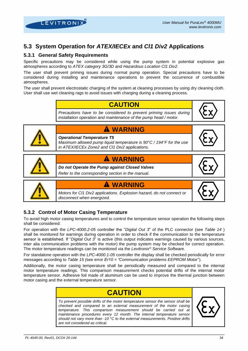
5.3 System Operation for ATEX/IECEx and Cl1 Div2 Applications
5.3.1 General Safety Requirements
Specific precautions may be considered while using the pump system in potential explosive gas atmospheres according to ATEX category 3G/3D and Hazardous Location Cl1 Div2.
The user shall prevent priming issues during normal pump operation. Special precautions have to be considered during installing and maintenance operations to prevent the occurrence of combustible atmospheres.
The user shall prevent electrostatic charging of the system at cleaning processes by using dry cleaning cloth. User shall use wet cleaning rags to avoid issues with charging during a cleaning process.
CAUTION
Precautions have to be considered to prevent priming issues during installation operation and maintenance of the pump head / motor.
! WARNING
Operational Temperature T5 Maximum allowed pump liquid temperature is 90°C / 194°F for the use in ATEX/IECEx Zone2 and Cl1 Div2 applications.
! WARNING
Do not Operate the Pump against Closed Valves
Refer to the corresponding section in the manual.
! WARNING
Motors for Cl1 Div2 applications. Explosion hazard, do not connect or disconnect when energized.
5.3.2 Control of Motor Casing Temperature
To avoid high motor casing temperatures and to control the temperature sensor operation the following steps shall be considered:
For operation with the LPC-4000.2-05 controller the “Digital Out 3” of the PLC connector (see Table 14 ) shall be monitored for warnings during operation in order to check if the communication to the temperature sensor is established. If “Digital Out 3” is active (this output indicates warnings caused by various sources, inter alia communication problems with the motor) the pump system may be checked for correct operation. The motor temperature readings can be monitored via the Levitronix® Service Software.
For standalone operation with the LPC-4000.1-05 controller the display shall be checked periodically for error messages according to Table 15 (see error Er10 = “Communication problems EEPROM Motor”).
Additionally, the motor casing temperature shall be periodically measured and compared to the internal motor temperature readings. This comparison measurement checks potential drifts of the internal motor temperature sensor. Adhesive foil made of aluminum can be used to improve the thermal junction between motor casing and the external temperature sensor.
CAUTION
To prevent possible drifts of the motor temperature sensor the sensor shall be checked and compared to an external measurement of the motor casing temperature. This comparison measurement should be carried out at maintenance procedures every 12 month. The internal temperature sensor should not vary more than -10 °C to the external measurements. Positive drifts are not considered as critical.

User Manual for PuraLev® 4000MU www.levitronix.com
PL-4045-00, Rev01, DCO# 20-144 35
6 Instructions for Use of Pump Head
6.1 Description and Preparation
6.1.1 Description
The LPP-4000 Multi-Use pump heads are designed for applications in the Life Science industries in connection with the PuraLev® 4000MU pump system components. The Pump Head is mounted to the Bearingless Motor (a MagLev drive motor) and the motor is connected to a controller generating the currents for rotation and the levitation of the impeller.
Figure 36: Multi-Use pump head LPP-4000.3 with motor
For cleaning or inspection purposes or replacement of parts it may be necessary to disassemble or replace the pump head. Before doing that, make yourself familiar with the following warnings, cautions and instructions.
6.1.2 Inspection Prior to Use
The pump head should be inspected prior to use for any damage. Do not use the pump head if any damage is found. Contact Levitronix® regarding return of any suspected pump head.
6.1.3 Traceability for Troubleshooting
Traceability for trouble shooting is assured with a 6 digit serial number located on the top of the pump head (see Figure 38).
6.2 General Warnings and Cautions
! WARNING
High Magnetic Field Strength of Pump Impeller.
The pump head contains a rotor magnet with high magnetic field strength. Pace maker may be influenced and magnetic field may lead to contusions. Keep distance to pace makers and handle pump heads with care.
CAUTION
Magnetic Forces
Pay attention to the magnetic forces when handling the pump head. It has to be avoided that magnetic parts are attracted, which can cause cracks or contamination. Specifically pay attention to the magnetic forces, when handling two pump heads or impellers at the same time. As an example The situations in the 4 pictures below shall be avoided.
! CAUTION
The rotating impeller could cause injury. Do not run the pump system when opening the pump head.
6.3 Replacement of Pump Head
6.3.1 Preparation After removal of a new pump head from its packaging assure that no metallic part is magnetically attaching to the pump head. Before insertion into the motor remove the Fixation Disks, which come delivered with the packaging in order to magnetically fix the impeller against movements during transportation.
Figure 37: Metallic Fixation Disks
Bearingless Motor LPM-4000.x
Pump Housing Top
Pump Housing Clamp
Impeller
Triclamp Sealing Gasket
Pump Housing Bottom
8 Screws M10x35mm with Spring Washers
(For fixation of clamp on motor)
2 Screws M6x30mm with Spring Washers
(For clamping of pump housing)
These situations have to be avoided!

User Manual for PuraLev® 4000MU www.levitronix.com
PL-4045-00, Rev01, DCO# 20-144 36
6.3.2 Power Down the System
Set the speed to 0 rpm, disable the system. After running at higher motor or liquid temperature the pump head might stick to the motor due to thermal expansion effects. In this case let the system cool down for a while before starting the replacement procedure.
6.3.3 Pump Head Removal from Motor
Untighten the screws S1 to S8, which fix the pump head to the motor (see Figure 38). Do not use the pump housing clamp screws P1 and P2. Remove the pump head axially and attach the Fixation Disks from the new pump head to it.
Figure 38: Screws of pump head
6.3.4 Insertion of Pump Head to Motor
Assure that on the new pump head the Fixation Disks are not attached anymore. Insert the pump head to the motor by placing the bottom of the pump head on the protecting cup of the motor and move it afterwards to the center until it locks in.
CAUTION
Take care of your fingers. Do not hold the pump head on the bottom because of risk to get the fingers squeezed.
6.3.5 Pump Fixation to Motor
Rotate the pump head outlet in the desired angle position and tighten the 8 clamp screws S1 to S8 together with the spring washers in the sequence as numbered in Figure 38. Use incremental torque steps in order to avoid to mounting the clamp asymmetrically to the motor. Maximum torque is 4 Nm.
For fine adjustment of the outlet position the two tangential screws P1 and P2 can be loosened (with untightened fixation screws S1-S8). Now the pump housing is freely rotatable within the clamps and can be oriented to the desired angle. Afterwards, all screws P1/P2 and S1-S8 must be re-fastened according to Section 6.4.2 and 6.3.5.
6.3.6 Start-Up and Functionality Check
Start up the system and check if the impeller is rotating properly. If the pump is not operating as expected make sure that one of the metallic Fixation Disks or another magnetic part has not accidentally attached itself to the
bottom of the pump head.
8 Screws M10x35mm (Screws S1-S8 for fixation of
pump head on motor)
2 Screws M6x30mm (Screws P1 and P2 for
clamping of pump housing)
S1
S2
S3
S4
P1
S5
S7
S8
S6
OK!
Don not forget Spring washers!
6 Digit Serial Number
P2
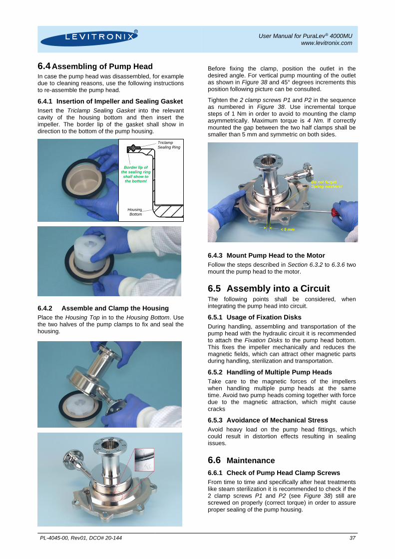
User Manual for PuraLev® 4000MU www.levitronix.com
PL-4045-00, Rev01, DCO# 20-144 37
6.4 Assembling of Pump Head In case the pump head was disassembled, for example due to cleaning reasons, use the following instructions to re-assemble the pump head.
6.4.1 Insertion of Impeller and Sealing Gasket
Insert the Triclamp Sealing Gasket into the relevant cavity of the housing bottom and then insert the impeller. The border lip of the gasket shall show in direction to the bottom of the pump housing.
6.4.2 Assemble and Clamp the Housing
Place the Housing Top in to the Housing Bottom. Use the two halves of the pump clamps to fix and seal the housing.
Before fixing the clamp, position the outlet in the desired angle. For vertical pump mounting of the outlet as shown in Figure 38 and 45° degrees increments this position following picture can be consulted.
Tighten the 2 clamp screws P1 and P2 in the sequence as numbered in Figure 38. Use incremental torque steps of 1 Nm in order to avoid to mounting the clamp asymmetrically. Maximum torque is 4 Nm. If correctly mounted the gap between the two half clamps shall be smaller than 5 mm and symmetric on both sides.
6.4.3 Mount Pump Head to the Motor
Follow the steps described in Section 6.3.2 to 6.3.6 two mount the pump head to the motor.
6.5 Assembly into a Circuit The following points shall be considered, when integrating the pump head into circuit.
6.5.1 Usage of Fixation Disks
During handling, assembling and transportation of the pump head with the hydraulic circuit it is recommended to attach the Fixation Disks to the pump head bottom. This fixes the impeller mechanically and reduces the magnetic fields, which can attract other magnetic parts during handling, sterilization and transportation.
6.5.2 Handling of Multiple Pump Heads
Take care to the magnetic forces of the impellers when handling multiple pump heads at the same time. Avoid two pump heads coming together with force due to the magnetic attraction, which might cause cracks
6.5.3 Avoidance of Mechanical Stress
Avoid heavy load on the pump head fittings, which could result in distortion effects resulting in sealing issues.
6.6 Maintenance
6.6.1 Check of Pump Head Clamp Screws
From time to time and specifically after heat treatments like steam sterilization it is recommended to check if the 2 clamp screws P1 and P2 (see Figure 38) still are screwed on properly (correct torque) in order to assure proper sealing of the pump housing.
Triclamp Sealing Ring
Housing Bottom
Border lip of the sealing ring shall show to the bottom!
< 5 mm
Do not forget Spring washers!

User Manual for PuraLev® 4000MU www.levitronix.com
PL-4045-00, Rev01, DCO# 20-144 38
7 Troubleshooting
7.1 Troubleshooting for Operation with Controller LPC-4000.1-05 For troubleshooting and failure analysis with the standalone controller LPC-4000.1-05 the following procedure is recommended:
- Check the status of the LEDs. The specific LEDs are described in Table 11
- Use the ERROR codes on the display. The specific error codes are described in Table 15
- A digital output on the “USER INTERFACE” connector (“Status”) indicates if the system is active. However, the source of an error cannot be identified by this signal
7.2 Troubleshooting for Operation with Controller LPC-4000.2-05 The integrated PLC provides a Warning and an Error signals according to Table 16. However, the source of error cannot be identified by these signals.
For more detailed analysis the Levitronix Service Software can be used with a PC and a USB interface to the controller.
7.3 Troubleshooting with Levitronix® Service Software The Levitronix Service Software allows communication with the pump system in connection with a PC and a USB interface. The software can be used for performing detailed troubleshooting.
Note: the Levitronix Service Software cannot be used with the standalone controller LPC-4000.1-05.
8 Technical Support For troubleshooting, support and detailed technical information contact Levitronix Technical Service department:
Levitronix Technical Service Department Technoparkstr. 1 CH-8005 Zurich Switzerland Phone for US: 888-569 07 18 Phone for outside US: +1 888-569 07 18 E-Mail: [email protected]
User Manual for PuraLev® 4000MU www.levitronix.com
PL-4045-00, Rev01, DCO# 20-144 39
9 Appendix
9.1 Regulatory Status
9.1.1 CE Marking The Centrifugal Pump System PuraLev® 4000MU, in its various configurations, is in conformity with the below mentioned European Directives. Machinery Directive 2006/42/EC:
The machinery directive essentially has been followed by a risk analysis, according mitigation actions and a user manual for safe operation. For the design and testing the following standards are used as a guideline:
EN809 Pumps for Fluids: basic requirements are followed.
EN12162 Procedure for hydrostatic pressure testing in fluid pumps: used for max. pressure testing of pump head.
ISO12100 Safety for machinery – principles for risk assessments: used for system risk analysis.
EMC Directive 2014/30/EC:
The following standards of the EMC directive are tested and confirmed at a certified laboratory:
EN61000-6-2 Generic standards, Immunity for industrial environments
EN61000-6-4 Generic standards, Emission standard for industrial environments
Low Voltage Directive 2014/35/EC:
The low voltage directive essentially has been followed by a risk analysis, according mitigation actions and a user manual for safe operation. For the design and testing the following standards are used as a guideline:
EN61010-1 Safety requirements for electrical equipment: 3rd party tested.
ISO12100 Safety for machinery – principles for risk assessments: used for system risk analysis.
9.1.2 Disposal of Equipment – WEEE Directive 2012/19/EU
Follow local legislation for disposal of equipment. In the European Union (EU) marked ( ) devices are governed by the European WEEE Directive 2012/19/EU. Do not dispose with normal waste.
9.1.3 IECEE CB Safety Certification
Specific motors with pump heads and controllers of the Centrifugal Pump System PuraLev® 4000MU are 3rd party tested and certified by Electrosuisse following the IECEE CB Scheme according to the following safety standards:
IEC61010-1 Safety requirements for electrical equipment for measurement, control and laboratory use.
The CB certification number is CH-7449.
9.1.4 NRTL/ETL Safety Certification and Marking
Specific motors with pump heads and controllers of the Centrifugal Pump System PuraLev® 4000MU are tested by the US national recognized laboratory (NRTL) Intertek according to the following safety standards:
UL61010-1 Safety requirements for electrical equipment for measurement, control and laboratory (US Standard).
CSA-C22.2 No. 61010-1-12
Safety requirements for electrical equipment for measurement, control and laboratory use (Canadian Standard).
UL1004-1 Rotating Electrical Machines - General Requirements (US standard).
The ETL control number for the listing is 4010272.

User Manual for PuraLev® 4000MU www.levitronix.com
PL-4045-00, Rev01, DCO# 20-144 40
9.1.5 ATEX / IECEx Marking
Specific motors together with the pump head of the PuraLev® 4000MU pump system are in conformity with the requirements of the Directive 2014/34/EU and the applicable IEC standards. The following standards are tested and confirmed at a certified laboratory.
IEC / EN 60079-0 Electrical apparatus for explosive gas atmospheres. General requirements.
IEC / EN 60079-15 Electrical Apparatus for explosive gas atmospheres. Construction, test and marking of type of protection, “nA” non-sparking electrical apparatus.
IEC / EN 60079-31 Explosive atmospheres – Part 31: Equipment dust ignition protection by enclosure “t”
IEC / EN 13463-5 Non-electrical equipment for use in potential explosive atmospheres – Part5: Protection by constructional safety “c”.
The Levitronix® Ex motors are marked clearly and in accordance to the ATEX / IECEx Directives and standards. The protection Ex nA means non sparking electrical apparatus.
II 3G Ex nA IIC T5 Gc
II 3D Ex tc IIIC T100°C Dc
Classification: Category 3GD (Zone 2 for Gas and Zone 22 for Dust)
Thermal Classification: Thermal classification of motor is T5 (< 100 °C = 212 °F) for maximum full-load operating temperature at a maximum liquid temperature of 90 °C / 194 °F.
9.1.6 Hazardous Location Cl1 Div2 Marking
Specific motors together with the pump head of the PuraLev® 4000MU pump system are in conformity with the requirements of the national electrical code NFPA-70 article 500. The following standards are tested and confirmed at a certified laboratory.
ISA 12.12.01:2016 Ed.7 Nonincendive Electrical Equipment For Use in Class 1 and 2, Division 2 and Class 3, Division 1 and 2 Hazardous (Classified) Locations
CSA C22.2#213:213 Ed.2 Nonincendive Electrical Equipment For Use in Class I and II, Division 2 and Class III, Divisions 1 and 2 Hazardous (Classified) Locations
The Levitronix® Cl1 Div2 motors are marked clearly and in accordance to the above mentioned standards.
US: Class I, Div 2 Groups A-D T5 Class I, Zone 2 Groups IIC T5
Class II, Div 2 Groups F-G T5 Zone 22 Groups IIIB T5 Canada: Class I, Div 2 Groups A-D T5
Class II, Div 2 Groups F-G T5
Classification: Class I, II (Zone 2 for Gas and Zone 22 for Dust)
Thermal Classification: Thermal classification of motor is T5 (< 100 °C = 212 °F) for maximum full-load operating temperature at a maximum liquid temperature of 90 °C / 194 °F.
9.1.7 Biocompatibility The wet materials of the LPP-4000 pump heads, in the configurations as listed below, satisfy the following biocompatibility specifications:
Part Name Impeller Material Housing Top Material
Housing Bottom Cup Material
Triclamp Gasket
LPP-4000.3 High Purity PFA Stainless Steel PEEK EPDM
FDA 21 CFR
All wet raw materials made of plastics used in the above mentioned pump heads meet specifications according to FDA 21 CFR (section 177.2415 for PEEK, 177.1550 for PFA, 177.2600 for EPDM). This statement is given in good faith and based on declarations provided by our raw material or component suppliers.

User Manual for PuraLev® 4000MU www.levitronix.com
PL-4045-00, Rev01, DCO# 20-144 41
USP VI
The wet raw materials made of plastics used in the above mentioned pump heads meet the specifications of USP Class VI. This statement is given in good faith and based on declarations provided by our raw material or component suppliers.
BSE/TSE Free
Based on declarations provided by the raw material and component suppliers, it is believed that the wet materials made out of plastics of the above mentioned pump heads do not contain potential spongiform or transmissible spongiform encephalopathy (BSE/TSE).

User Manual for PuraLev® 4000MU www.levitronix.com
PL-4045-00, Rev01, DCO# 20-144 42
9.2 Symbols and Signal Words
Symbol / Signal Word
Description Type Source
DANGER Indication of an imminently hazardous situation that, if not avoided, will result in death or severe injury. Limited to the most extreme situation
Signal word SEMI S1-0701
WARNING Indication of a potentially hazardous situation which, if not avoided, could result in death or severe injury.
Signal word SEMI S1-0701
CAUTION
Indication of potentially hazardous situations which, if not avoided, could result in moderate or minor injury. Also alert against unsafe practice.
Without safety alert indication of hazardous situation which, if not avoided, could result in property damage.
Signal word SEMI S1-0701
!
Safety alert for “Warning” and “Caution” Safety alert SEMI S1-0701
!
Safety alert for “Danger” Safety alert SEMI S1-0701
Caution (refer to accompanying documents) (is used on article labels for reference to manual)
Refer to manual ISO 3864
Toxic material, poison Hazard identification IEC 61310
Corrosive material, corrosion Hazard identification IEC 61310
Cut/sever hand, sharp object Hazard identification ANSI Z535.3
Strong magnetic field Hazard identification SEMI S1-0701
Danger: electricity, electrical hazard Hazard identification IEC 61310, ISO 3864
Wear safety gloves Hazard avoidance Mandatory action
IEC 61310
Wear face shield Hazard avoidance Mandatory action
SEMI S1-0701
No pacemakers Hazard avoidance
Prohibition SEMI S1-0701
ATEX Logo Used for hazard
identificat. in warnings --
Table 17: Safety symbols and signal words


![Page 1 of 5 - Levitronix...semiconductor manufacturing increases the likelihood of surface defectivicy during C MP.]" 7 To reduce/minimize process dependent defectivity, the particle](https://static.fdocuments.in/doc/165x107/6086cd62d5bc1303bd751340/page-1-of-5-levitronix-semiconductor-manufacturing-increases-the-likelihood.jpg)