Pumps and Turbines ME 268 - Bangladesh University of ...teacher.buet.ac.bd/mislam/ME268.pdf ·...
52
Turbo Machines Turbo Machines Pumps and Turbines ME 268 ME 268
Transcript of Pumps and Turbines ME 268 - Bangladesh University of ...teacher.buet.ac.bd/mislam/ME268.pdf ·...
Turbo MachinesTurbo MachinesPumps and Turbines
ME 268ME 268
Turbo Machines
Turbo machines are dynamic fluid machines that either extract energy from a fluid (turbine) or add energy to a fluid (pump) as a result of dynamic interactions between th d i d th fl id (L ti T b t ithe device and the fluid. (Latin Turbomeans to spin or whirl)
Classifications
According to energy considerationMachines that supply energy to fluid (Pumps)An increase in pressure takes place in pumps, fans,
d llcompressors and propellers.
Machines that extracts energy from fluid (Turbines)A decrease in pressure takes place in turbines wind millsA decrease in pressure takes place in turbines, wind mills.
Machines that are a combination of both (Energy transmitters and torque converters)
Classifications (contd…)
Based on direction of flowAxial flow
Radial flow
Mixed flow
Based on the manner of transmission of energyKinetic displacement (Centrifugal pumps and turbines)
Positive displacement (Reciprocating pumps)
Pumps
Pumps
A pump is a device used to move liquids or slurries. A p p qpump moves liquids or gases from lower pressure to higher pressure, and overcomes this difference in pressure by adding energy to the system.
Mechanical Energy Hydraulic energy
Pumps
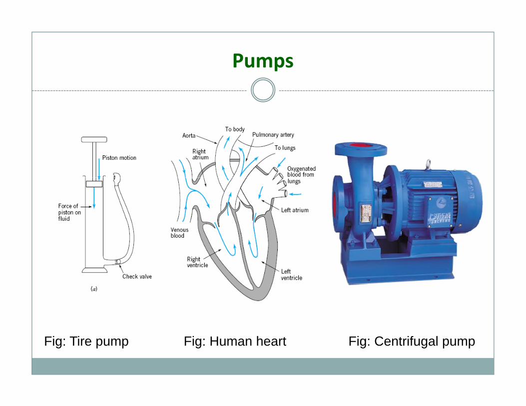
Fig: Tire pump Fig: Human heart Fig: Centrifugal pump
Pumps Classification (contd)…
Pumps are divided into two fundamental types based on the h h h h d dmanner in which they transmit energy to the pumped media:
kinetic or positive displacement.In kinetic displacement, a centrifugal force of the rotating p , g gelement, called an impeller, “impels” kinetic energy to the fluid, moving the fluid from pump suction to the discharge. Positive displacement uses the reciprocating action of one orPositive displacement uses the reciprocating action of one or several pistons, or a squeezing action of meshing gears, or other moving bodies, to displace the fluid from one area into
th (i i th t i l f ti t di h )another (i.e., moving the material from suction to discharge). Sometimes the terms ‘inlet’ (for suction) and ‘exit’ or ‘outlet’ (for discharge) are used.( g )
Pumps Applications
To deliver fluid at a higher elevation or at a long g gdistance.
To deliver fluid at a pressurized device
For the control of hydraulic systems
For drainage system, removing slurries, mud, waterg y g
For irrigation systems
Centrifugal Pumps
The hydraulic machines that converts the mechanical energy into pressure energy by means of centrifugal force acting on the fluid are called centrifugal pumps.
Centrifugal pump is radial flow type.
Used for high head and relatively low flow rate
3 important parts areImpeller
V l iVolute casing
Suction and delivery pipes.
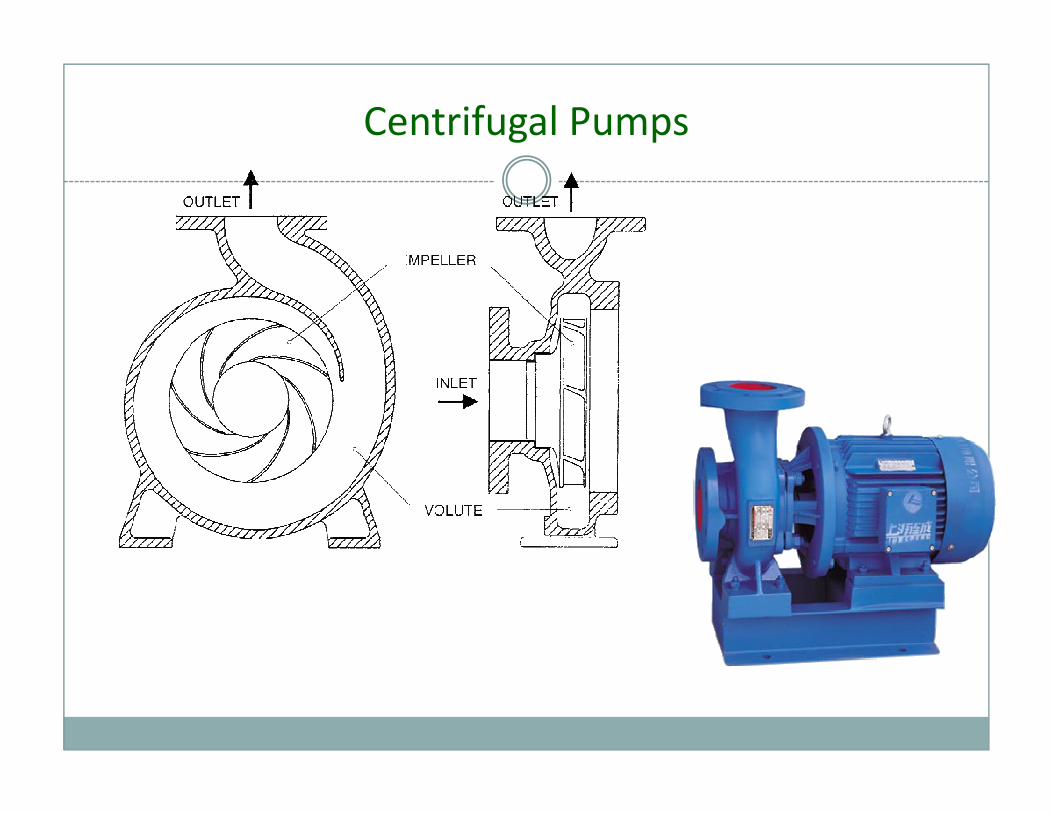
Centrifugal Pumps
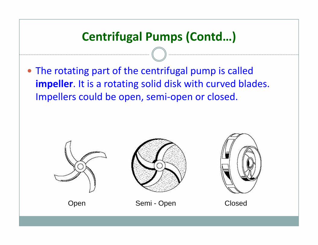
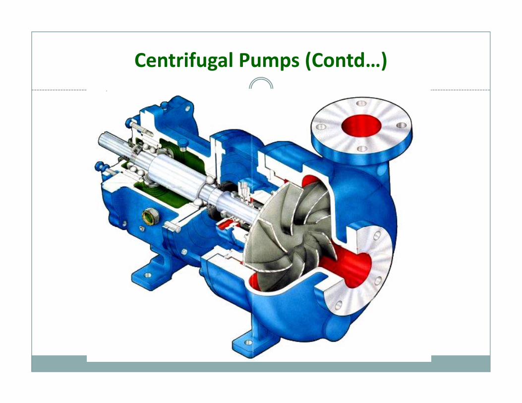
Centrifugal Pumps (Contd…)
The rotating part of the centrifugal pump is called impeller. It is a rotating solid disk with curved blades. Impellers could be open, semi‐open or closed.
Open Semi - Open Closed
Centrifugal Pumps (Contd…)
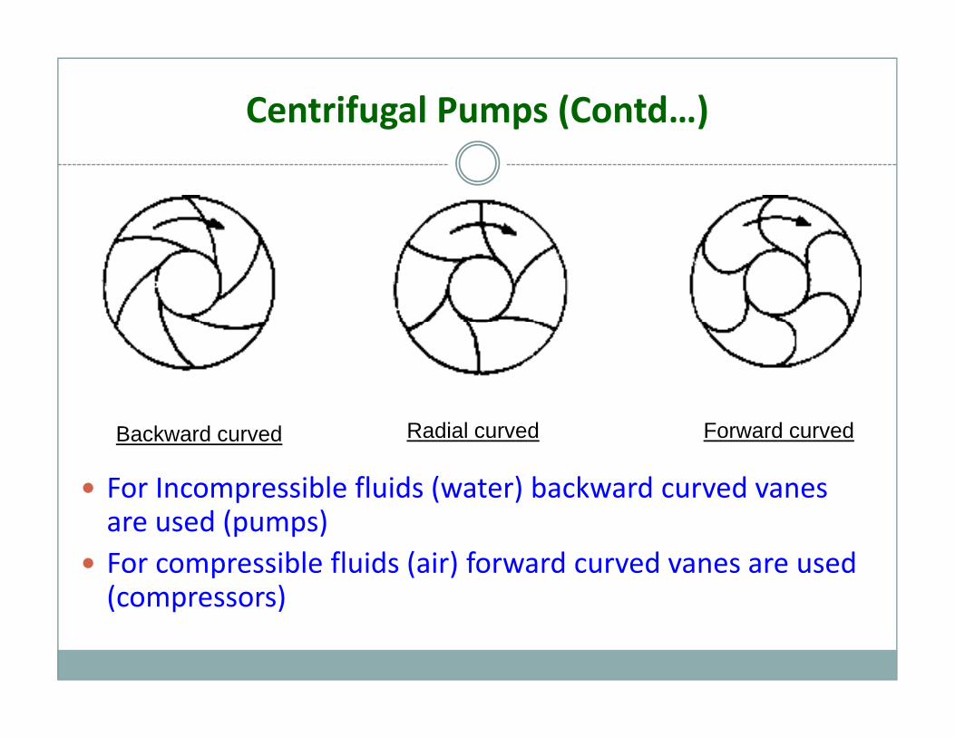
For Incompressible fluids (water) backward curved vanes
Backward curved Radial curved Forward curved
are used (pumps)For compressible fluids (air) forward curved vanes are used (compressors)(compressors)
Centrifugal Pumps (Contd…)
Casing is an airtight passage surrounding the impeller which converts the kinetic energy of the fluid leaving the impeller into pressure energy.
Suction pipe is connected to the inlet of the pump and th id i di d i t th fl id i D li iother side is dipped into the fluid in a sump. Delivery pipe
is connected to the outlet of the pump and other end delivers the fluid at required heightdelivers the fluid at required height.
Centrifugal Pumps (Contd…)
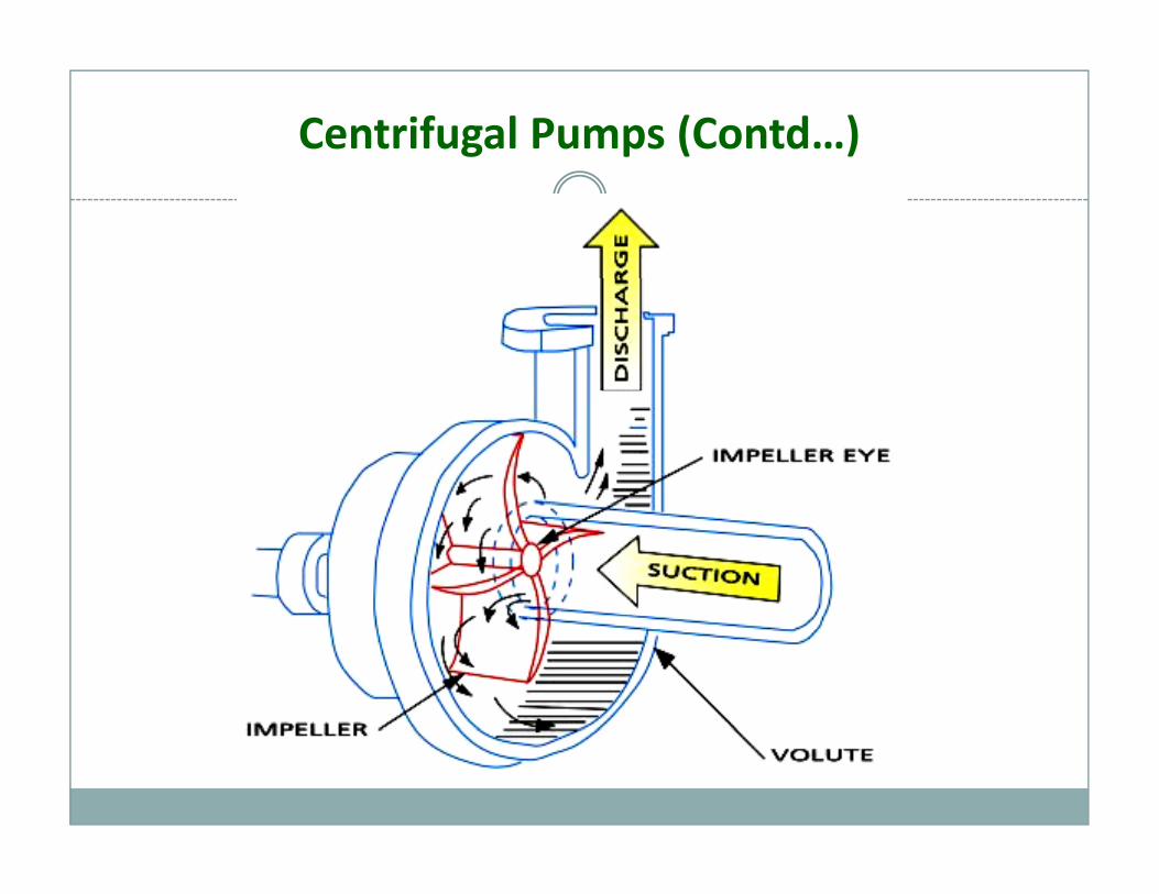
Working principle
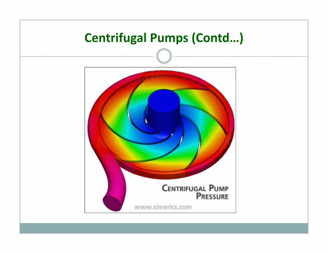
The impeller is keyed onto a shaft which is mounted on bearings and is coupled to a motor which rotates the impellerimpeller.The kinetic energy of the impeller is transmitted to the fluid and its velocity increases.Th l t i t th ki ti f th fl idThe volute casing converts the kinetic energy of the fluid to pressure energy. The pressure at the center of the impeller (eye) decreases as the fluid flows outward. The d i th fl id f th tdecrease in pressure causes the fluid of the sump to continuously flow through the suction pipes.The high pressure fluid is delivered through the delivery ipipe.
Centrifugal Pumps (Contd…)
Centrifugal Pumps (Contd…)
Centrifugal Pumps (Contd…)
Centrifugal Pumps (Contd…)
Priming
The pump casing must be filled with liquid before the pump is started, or the pump will not be able to function.
A pump is said to be primed when all the air in suction i i d i d li i t th l ipipe, casing, and in delivery pipe up to the valve is
driven out and its place is occupied by liquid to be pumpedpumped.
Centrifugal Pumps (Contd…)
Cavitations
If the suction pressure at the eye of the impeller falls below the vapor pressure of the fluid being pumped, the fluid will start to boilstart to boil.
Any vapor bubbles formed by the pressure drop at the eye of the impeller are swept along the impeller vanes by the p p g p yflow of the fluid. When the bubbles enter a region where local pressure is greater than saturation pressure farther out th i ll th b bbl b tl llthe impeller vane, the vapor bubbles abruptly collapse.
This phenomenon is called cavitation.
Centrifugal Pumps (Contd…)
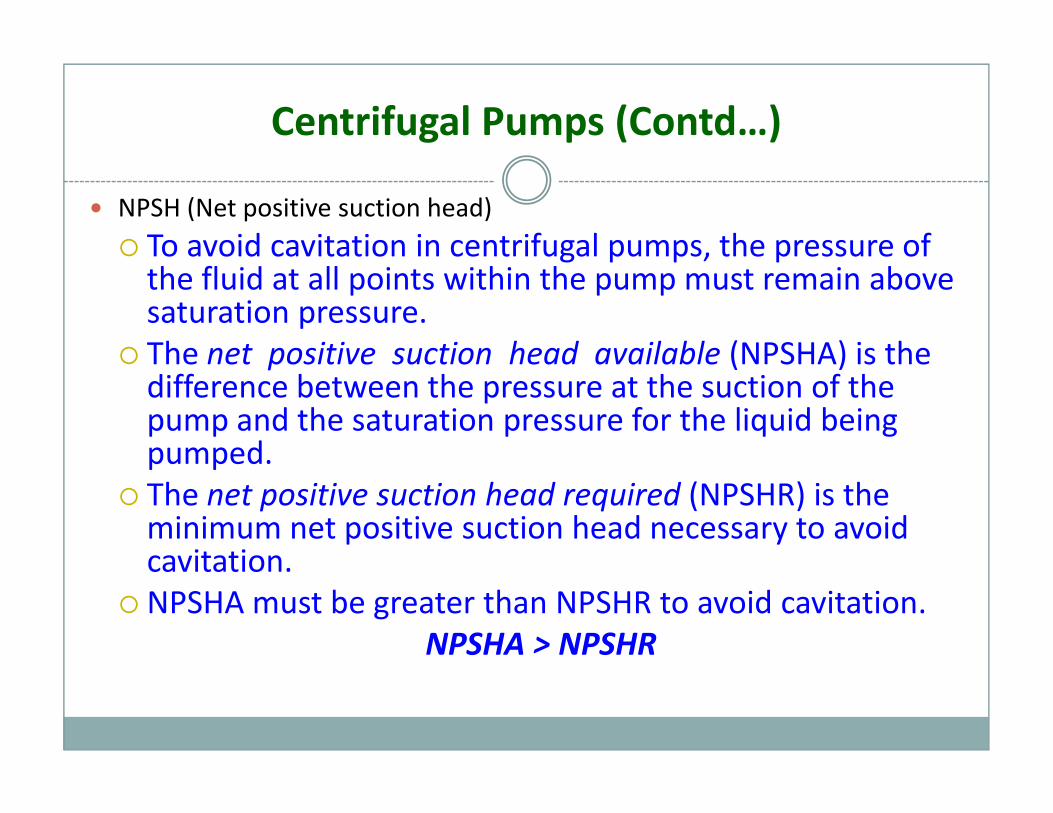
NPSH (Net positive suction head)To avoid cavitation in centrifugal pumps, the pressure ofTo avoid cavitation in centrifugal pumps, the pressure of the fluid at all points within the pump must remain above saturation pressure. The net positive suction head available (NPSHA) is theThe net positive suction head available (NPSHA) is the difference between the pressure at the suction of the pump and the saturation pressure for the liquid being pumpedpumped.The net positive suction head required (NPSHR) is the minimum net positive suction head necessary to avoid cavitationcavitation.NPSHA must be greater than NPSHR to avoid cavitation.
NPSHA > NPSHR
Centrifugal Pumps (Contd…)
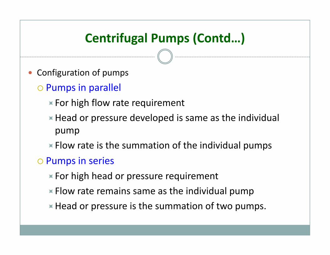
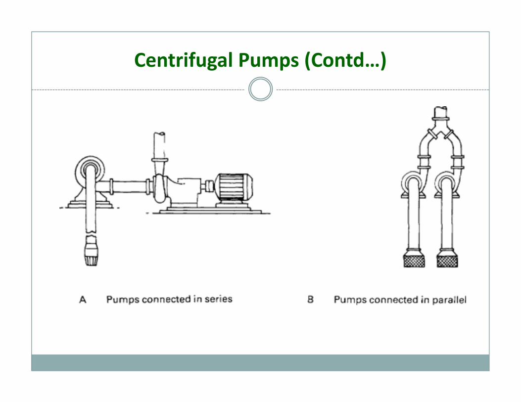
Configuration of pumps
Pumps in parallelFor high flow rate requirement
Head or pressure developed is same as the individual pump
Flow rate is the summation of the individual pumpsFlow rate is the summation of the individual pumps
Pumps in seriesFor high head or pressure requirementFor high head or pressure requirement
Flow rate remains same as the individual pump
Head or pressure is the summation of two pumpsHead or pressure is the summation of two pumps.
Centrifugal Pumps (Contd…)
Centrifugal Pumps (Contd…)
High velocity vs. High pressure
Water can be raised from one level to a higher level in two ways – High pressure and High velocity
High velocity method is very inefficient since the friction increases with proportional to the square of the l itvelocity
High pressure method is efficient because of low velocity and frictionvelocity and friction.
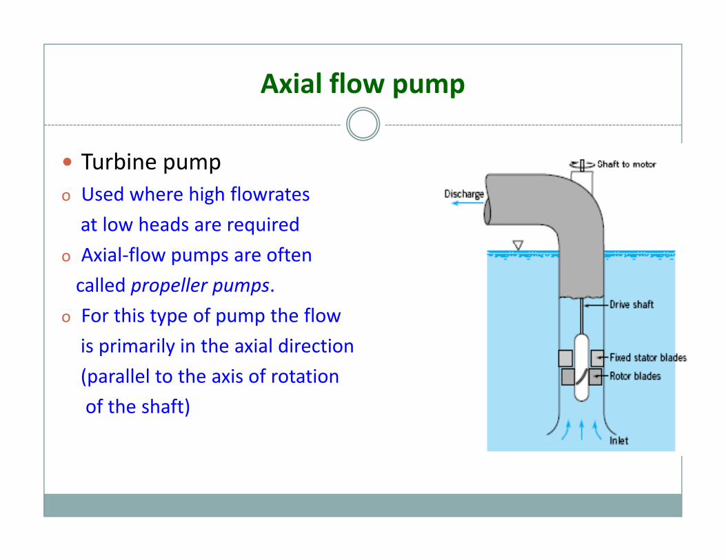
Axial flow pump
Turbine pumpo Used where high flowrates
at low heads are required
o Axial‐flow pumps are often
called propeller pumps.
o For this type of pump the flowo For this type of pump the flow
is primarily in the axial direction
(parallel to the axis of rotation(p
of the shaft)
Centrifugal Pumps (Contd…)
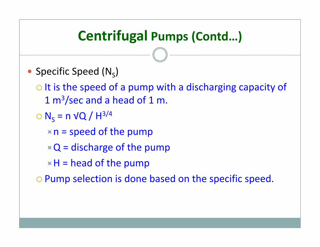
Specific Speed (NS)SIt is the speed of a pump with a discharging capacity of 1 m3/sec and a head of 1 m.
NS = n √Q / H3/4
n = speed of the pump
Q = discharge of the pump
H = head of the pump
Pump selection is done based on the specific speed.
Positive Displacement Pumps
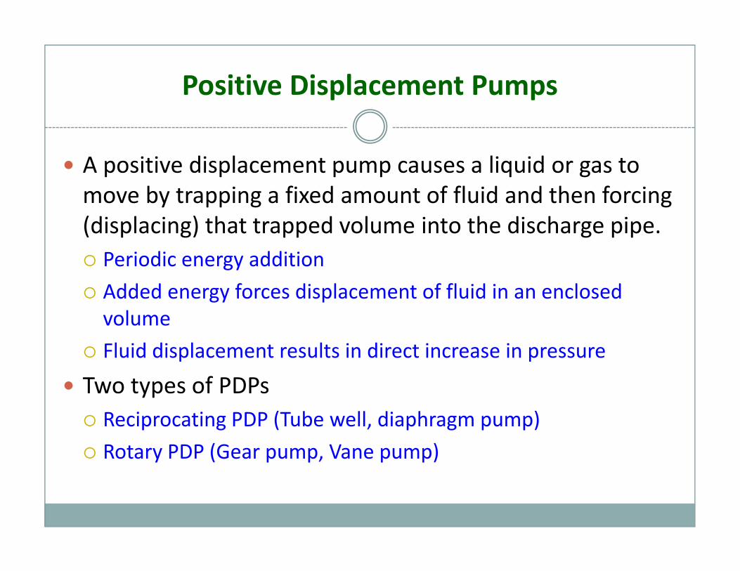
A positive displacement pump causes a liquid or gas to move by trapping a fixed amount of fluid and then forcing (displacing) that trapped volume into the discharge pipe.Periodic energy addition
Added energy forces displacement of fluid in an enclosed volumevolume
Fluid displacement results in direct increase in pressure
Two types of PDPsypReciprocating PDP (Tube well, diaphragm pump)
Rotary PDP (Gear pump, Vane pump)
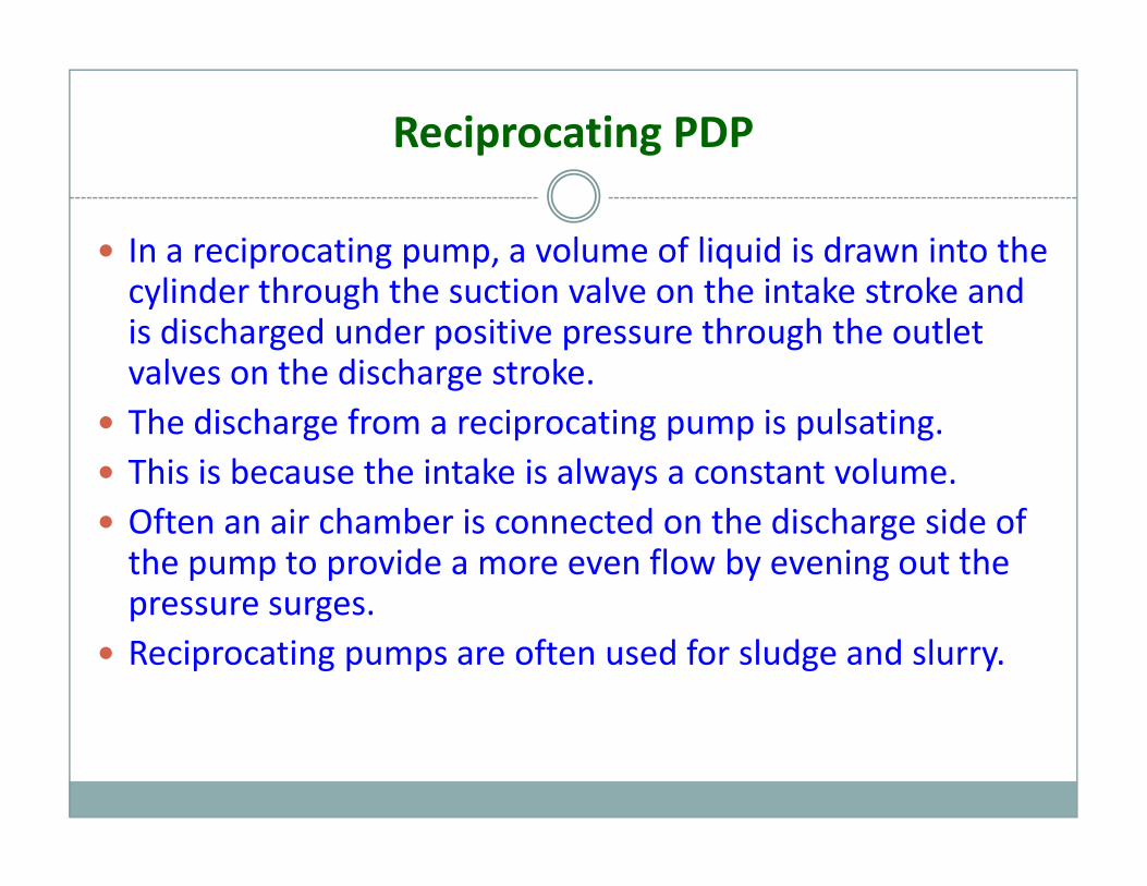
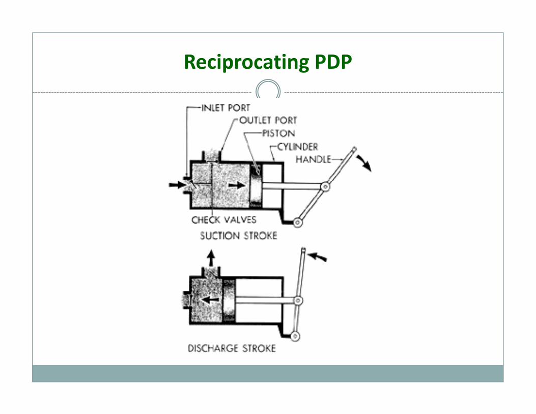
Reciprocating PDP
In a reciprocating pump, a volume of liquid is drawn into the cylinder through the suction valve on the intake stroke and is discharged under positive pressure through the outlet valves on the discharge stroke.gThe discharge from a reciprocating pump is pulsating.This is because the intake is always a constant volume.Often an air chamber is connected on the discharge side of the pump to provide a more even flow by evening out the pressure surges.pressure surges.Reciprocating pumps are often used for sludge and slurry.
Reciprocating PDP
Turbines
Turbines
Turbines are devices that convert the energy of fluid into mechanical energy.
The fluid can be water, steam, flue gas etc
The energy of the water can be in the form of potential or kinetic energy.
Steam turbine and gas turbine uses the thermal energy of steam and flue gas respectively.
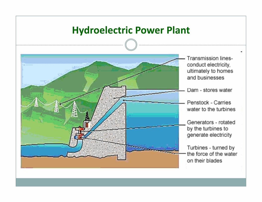
Hydroelectric Power Plant
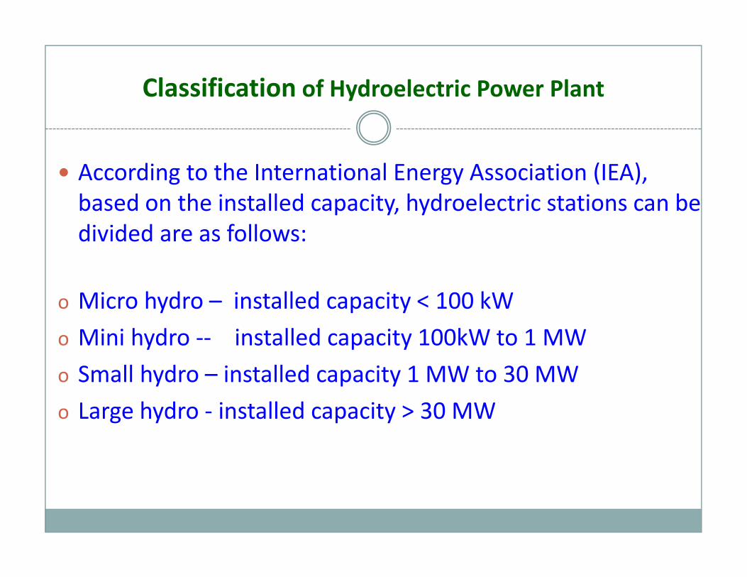
Classification of Hydroelectric Power Plant
According to the International Energy Association (IEA),According to the International Energy Association (IEA), based on the installed capacity, hydroelectric stations can be divided are as follows:
o Micro hydro – installed capacity < 100 kW
o Mini hydro ‐‐ installed capacity 100kW to 1 MW
o Small hydro – installed capacity 1 MW to 30 MW
o Large hydro ‐ installed capacity > 30 MW
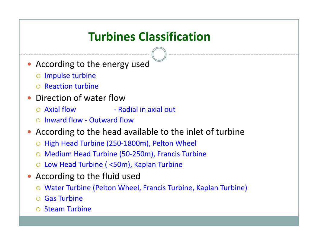
Turbines Classification
According to the energy usedImpulse turbineImpulse turbineReaction turbine
Direction of water flowA i l fl R di l i i lAxial flow ‐ Radial in axial outInward flow ‐ Outward flow
According to the head available to the inlet of turbineHigh Head Turbine (250‐1800m), Pelton WheelMedium Head Turbine (50‐250m), Francis TurbineLow Head Turbine ( <50m), Kaplan Turbine
According to the fluid usedWater Turbine (Pelton Wheel, Francis Turbine, Kaplan Turbine)Gas TurbineGas TurbineSteam Turbine
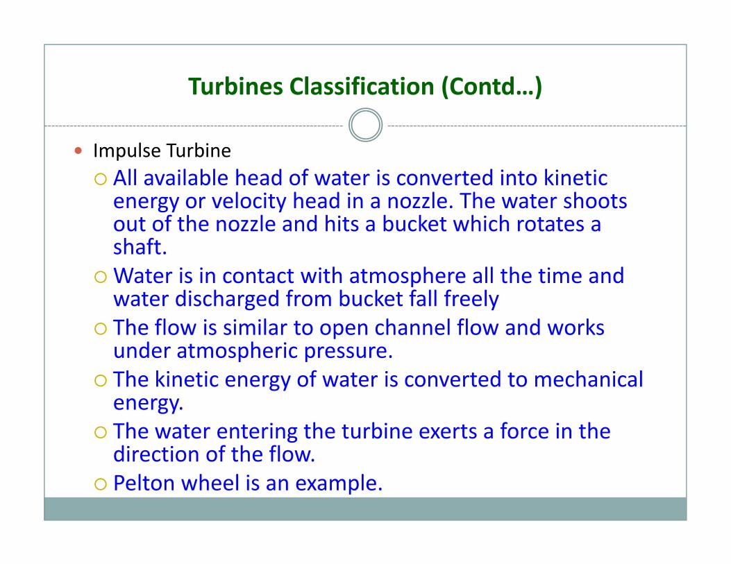
Turbines Classification (Contd…)
Impulse TurbineAll available head of water is converted into kineticAll available head of water is converted into kinetic energy or velocity head in a nozzle. The water shoots out of the nozzle and hits a bucket which rotates a shaftshaft.Water is in contact with atmosphere all the time and water discharged from bucket fall freelyThe flow is similar to open channel flow and works under atmospheric pressure.The kinetic energy of water is converted to mechanical gyenergy.The water entering the turbine exerts a force in the direction of the flow.direction of the flow.Pelton wheel is an example.
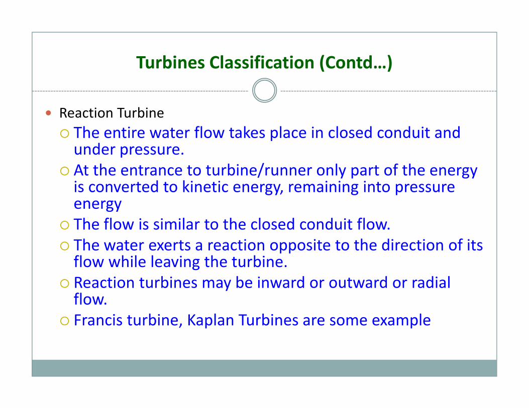
Turbines Classification (Contd…)
Reaction Turbineh i fl k l i l d d i dThe entire water flow takes place in closed conduit and under pressure.At the entrance to turbine/runner only part of the energy y p gyis converted to kinetic energy, remaining into pressure energyThe flow is similar to the closed conduit flow.The water exerts a reaction opposite to the direction of its flow while leaving the turbine.Reaction turbines may be inward or outward or radialReaction turbines may be inward or outward or radial flow.Francis turbine, Kaplan Turbines are some example
Impulse Turbine
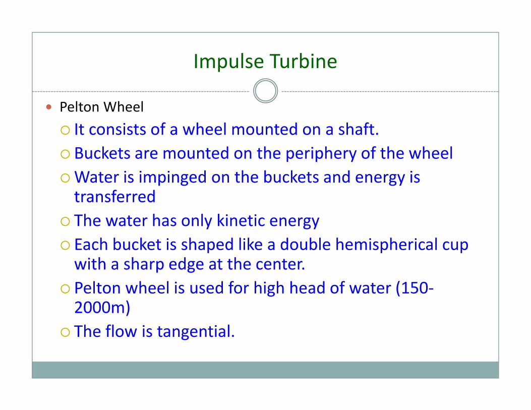
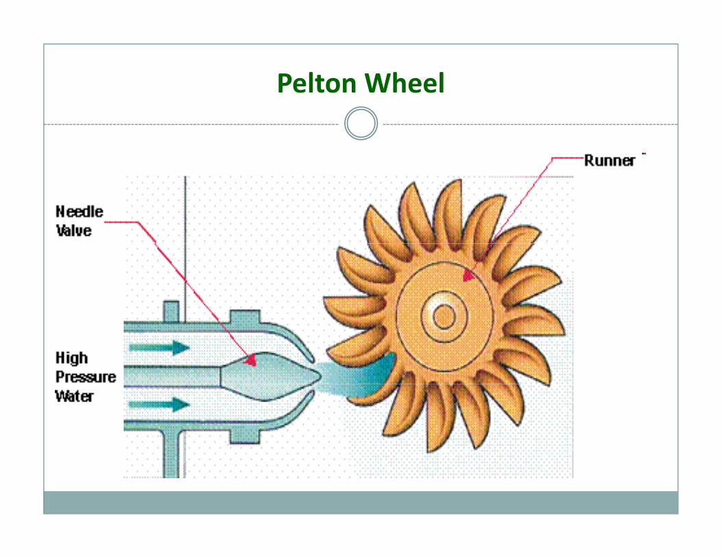
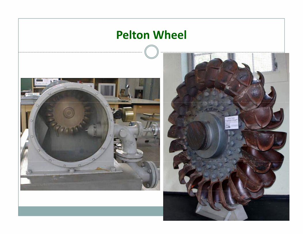
Pelton Wheel
It consists of a wheel mounted on a shaftIt consists of a wheel mounted on a shaft.Buckets are mounted on the periphery of the wheelWater is impinged on the buckets and energy isWater is impinged on the buckets and energy is transferredThe water has only kinetic energyEach bucket is shaped like a double hemispherical cup with a sharp edge at the center.P l h l i d f hi h h d f (150Pelton wheel is used for high head of water (150‐2000m)The flow is tangentialThe flow is tangential.
Pelton Wheel
Pelton Wheel
Reaction Turbine
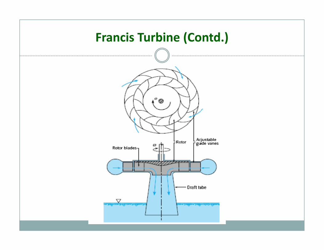
Francis Turbineo The Francis turbine is a reaction turbine which means thato The Francis turbine is a reaction turbine, which means that the working fluid changes pressure as it moves through the turbine, giving up its energy.
o The water enters into a casing with a relatively low velocity, passes through guide vanes located around the circumference and flows through the runner and finally discharges into aand flows through the runner and finally discharges into a draft tube sealed below the tailwater level.
Th f h h d il i l lo The water passage from the headrace to tail race is completely filled with water which acts upon the whole circumference of the runner.
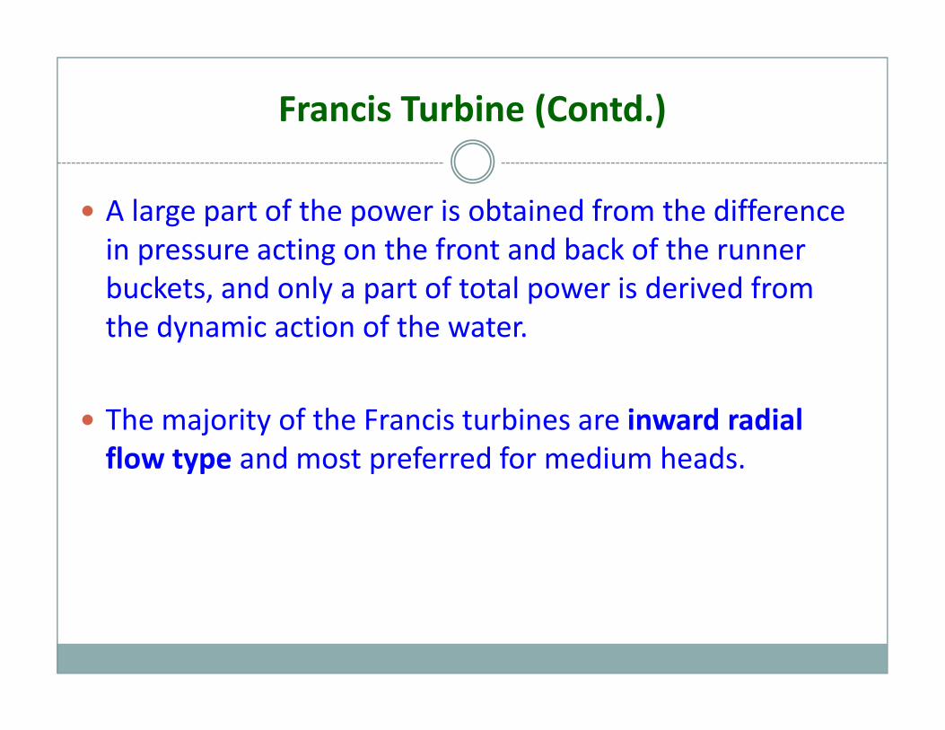
Francis Turbine (Contd.)
A large part of the power is obtained from the difference in pressure acting on the front and back of the runner buckets, and only a part of total power is derived from th d i ti f th tthe dynamic action of the water.
Th j it f th F i t bi i d di lThe majority of the Francis turbines are inward radial flow type and most preferred for medium heads.
Francis Turbine (Contd.)
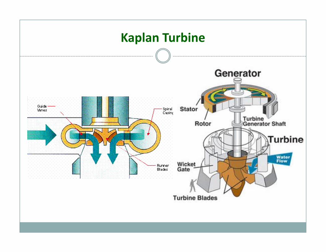
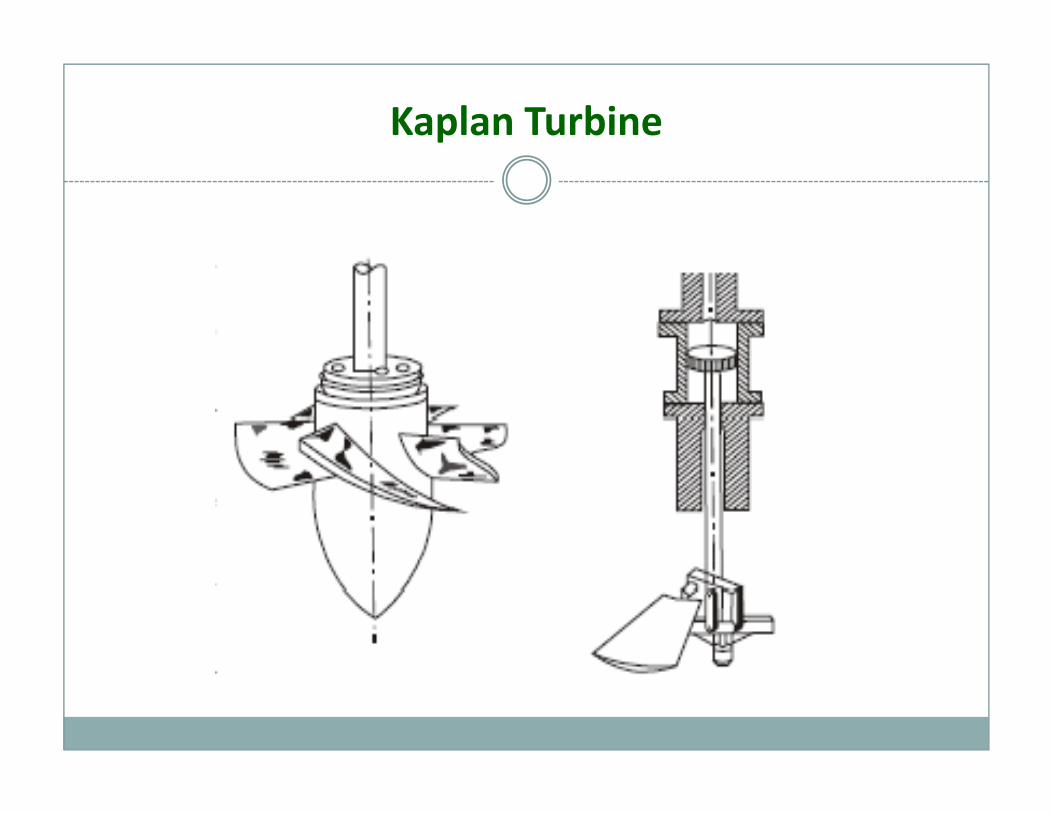
Kaplan Turbine
The Kaplan turbine is a propeller‐type water turbine that h dj t bl bl dhas adjustable blades.It is an inward flow reaction turbineBecause of the adjustable blades it is possible to run atBecause of the adjustable blades it is possible to run at maximum efficiency at any loadWater flows through the guide vanes, and then flows axially through the runnersaxially through the runners.The runner blade angles can be changed by a lever.It can work on very low head but requires high flow rate.y q g
Kaplan Turbine
Kaplan Turbine
Application of Turbines
Almost all electrical power on Earth is produced with a turbine of some type. Very high efficiency turbines harness about 40% of the thermal energy with the rest exhausted as waste heatthermal energy, with the rest exhausted as waste heat. Most jet engines rely on turbines to supply mechanical work from their working fluid and fuel as do all nuclear gships and power plants.
Gas Turbine
Gas turbine works due to the flow of flue gas through the stator and runner bladesstator and runner blades.Gas turbines have 3 major componentsCompressorCombustion chamberTurbine
Compressor compresses air and supplies it to the combustionCompressor compresses air and supplies it to the combustion chamber.In the combustion chamber the fuel is burnt with the help of the compressed air and the product of combustion also called flue gas is flowed through the turbineThe flue gas moves the turbine blades.The flue gas moves the turbine blades.
Gas Turbine Application
Gas turbine has two major applicationsIn power generationFor propulsion (Jet Engine)
I ti th i t t i t t t th tIn power generation the main target is to rotate the generator shaft with the help of the turbine.In the propulsion engines, the main target of the turbine is only to run the compressor. The Flue gas while getting out of the turbine gives a reaction force which gives the propulsion. (Jet engine)In modern aircraft engine, the turbine also acts as a propeller. In this type of engine only 25% of the propulsion comes from the reaction of the flue gas and the remaining 75% propulsionthe reaction of the flue gas and the remaining 75% propulsion comes from the propelling action. (Turboprop, Turbofan)
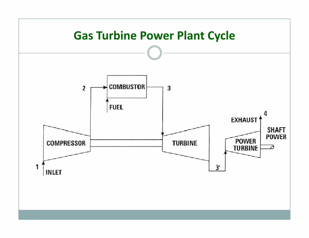
Gas Turbine Power Plant Cycle
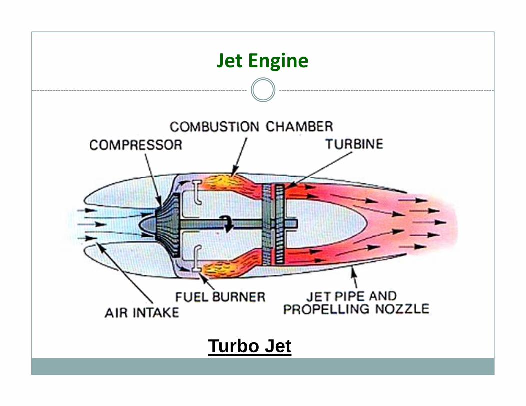
Jet Engine
Turbo Jet
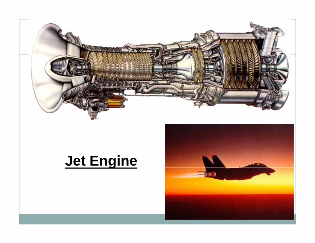
Jet Engineg

The End


![WELCOME [teacher.buet.ac.bd]teacher.buet.ac.bd/ziawadud/documents/seraj.pdf · welcome to the presentation on ... typical sheltech organogram of construction management. may 24, ...](https://static.fdocuments.in/doc/165x107/5a858de47f8b9ad30c8c768a/welcome-to-the-presentation-on-typical-sheltech-organogram-of-construction.jpg)