PUMPING CENTER MAXILUBE - LubriflexThe pumping center comprises of a hydraulic part (pos. 1),...
22
SAFEGREASE 2 MAXILUBE MMAX1FEN.doc 11.01.2007 Rev. 1F PUMPING CENTER MAXILUBE TABLE OF CONTENTS 1 GENERAL DESCRIPTION ................................................................................................................................ 1 2 DESIGN ............................................................................................................................................................. 1 2.1 Maxilube-ECO............................................................................................................................................. 1 2.2 Maxilube-STA.............................................................................................................................................. 1 3 OPERATION...................................................................................................................................................... 2 3.1 Start-up ....................................................................................................................................................... 2 3.1.1 Maxilube-ECO ...................................................................................................................................... 2 3.1.2 Maxilube-STA ....................................................................................................................................... 3 3.2 Changing the lubricant barrel ...................................................................................................................... 4 3.2.1 Maxilube-ECO ...................................................................................................................................... 4 3.2.2 Maxilube-STA ....................................................................................................................................... 5 3.3 Manual operation ........................................................................................................................................ 6 4 SETTINGS ......................................................................................................................................................... 7 5 TECHNICAL SPECIFICATION.......................................................................................................................... 7 5.1 Technical specifications .............................................................................................................................. 7 5.2 Connections ................................................................................................................................................ 7 5.3 Symbols ...................................................................................................................................................... 8 6 LID SETS ........................................................................................................................................................... 9 6.1 Maxilube-ECO............................................................................................................................................. 9 6.2 Maxilube-STA.............................................................................................................................................. 9 7 SPARE PARTS.................................................................................................................................................. 9 12 APPENDICES
Transcript of PUMPING CENTER MAXILUBE - LubriflexThe pumping center comprises of a hydraulic part (pos. 1),...

SAFEGREASE 2 MAXILUBE
MMAX1FEN.doc 11.01.2007 Rev. 1F
PUMPING CENTER MAXILUBE
TABLE OF CONTENTS
1 GENERAL DESCRIPTION................................................................................................................................1 2 DESIGN .............................................................................................................................................................1
2.1 Maxilube-ECO.............................................................................................................................................1 2.2 Maxilube-STA..............................................................................................................................................1
3 OPERATION......................................................................................................................................................2 3.1 Start-up .......................................................................................................................................................2
3.1.1 Maxilube-ECO ......................................................................................................................................2 3.1.2 Maxilube-STA.......................................................................................................................................3
3.2 Changing the lubricant barrel......................................................................................................................4 3.2.1 Maxilube-ECO ......................................................................................................................................4 3.2.2 Maxilube-STA.......................................................................................................................................5
3.3 Manual operation ........................................................................................................................................6 4 SETTINGS.........................................................................................................................................................7 5 TECHNICAL SPECIFICATION..........................................................................................................................7
5.1 Technical specifications ..............................................................................................................................7 5.2 Connections ................................................................................................................................................7 5.3 Symbols ......................................................................................................................................................8
6 LID SETS...........................................................................................................................................................9 6.1 Maxilube-ECO.............................................................................................................................................9 6.2 Maxilube-STA..............................................................................................................................................9
7 SPARE PARTS..................................................................................................................................................9
12 APPENDICES

SAFEGREASE 2 MAXILUBE
MMAX1FEN.doc 11.01.2007 Rev. 1F
1 (9)
PUMPING CENTER MAXILUBE
1 GENERAL DESCRIPTION
The pumping center is designed for pumping lubricant into the system.
2 DESIGN
2.1 Maxilube-ECO
Pumping center Maxilube-ECO is equipped with a lid set which is axially descending.
Note Numbers in brackets are part numbers of drawing 461982.
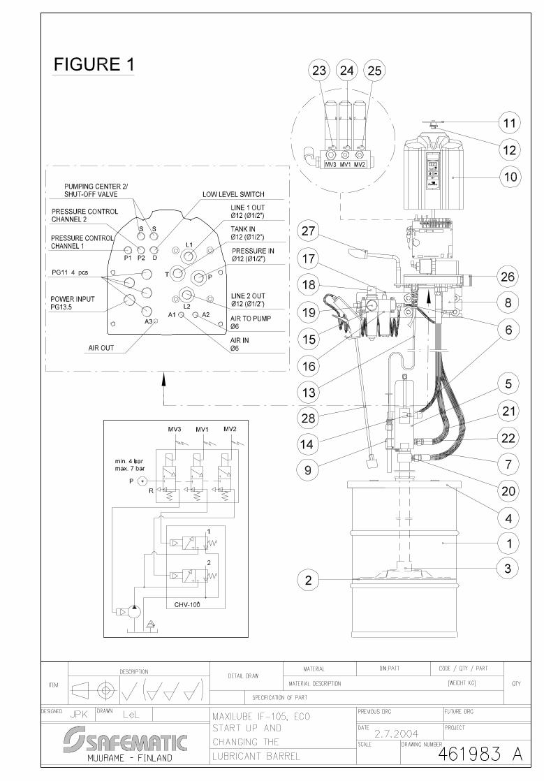
The pumping center comprises of a hydraulic part (pos. 1), pressure air regulator (pos. 2) and a barrel pump (pos. 3) and its additional equipment. The hydraulic part includes a solenoid valve group (pos. 4), a directional valve group (pos. 5), pressure gauges (pos. 6) and a fixing plate (pos. 7) including a bracket for the pump which can be used during barrel change procedures. The pressure air regulator contains an air gun (pos. 8) for lifting the follower plate.
The pumping center can be controlled and monitored by an integrated control unit, with SMS-messages or with external control. The control unit contains a user interface (pos. 9) and a circuit board (pos. 10). SMS-control contains a GSM-modem (pos. 11) and an antenna (pos. 12).
The pump is delivered with the following additional pieces of equipment: barrel lid (pos. 13), follower plate (pos. 14), barrel low level switch (pos. 15) and grease filter (pos. 16).
Note The follower plate is not used with grease or oils of NLGI 0, 00 and 000 classes.
2.2 Maxilube-STA
Pumping center Maxilube-STA is equipped with a lid set which is stationary.
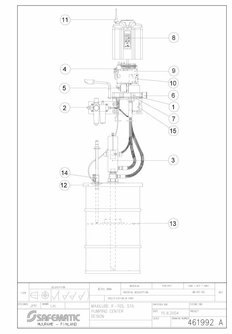
Note Numbers in brackets are part numbers of drawing 461992A.
The pumping center comprises of a hydraulic part (pos. 1), pressure air regulator (pos. 2) and a barrel pump (pos. 3) and its additional equipment. The hydraulic part includes a solenoid valve group (pos. 4), a directional valve group (pos. 5), pressure gauges (pos. 6) and a fixing plate (pos. 7) including a bracket for the pump which can be used during barrel change procedures.
The pumping center can be controlled and monitored by an integrated control unit, with SMS-messages or with external control. The control unit contains a user interface (pos. 8) and a circuit board (pos. 9). SMS-control contains a GSM-modem (pos. 10) and an antenna (pos. 11).
The pump is delivered with the following additional pieces of equipment: barrel lid (pos. 12), follower plate (pos. 13), barrel low level switch (pos. 14) and grease filter (pos. 15).
Note The follower plate is not used with grease or oils of NLGI 0, 00 and 000 classes.

SAFEGREASE 2 MAXILUBE
MMAX1FEN.doc 11.01.2007 Rev. 1F
2 (9)
3 OPERATION
When pressurization starts, control unit opens both the line to be pressurized and the pump solenoid valves. Pressure air starts the pump and opens the line directional valve. Pressurization continues until the pressure control unit of the line reaches the acknowledgement pressure level. After acknowledgement the control unit closes the solenoid valves, the pump stops and pressure discharges from the line to the lubricant barrel.
If the lubricant level in the barrel reaches the low limit level during pumping, the low level switch sends an alarm to the control unit and pumping is stopped. The alarm can be disabled by changing the lubricant barrel and resetting the alarm at the control unit.
3.1 Start-up
Caution Ensure that the pumping center is turned off when the connections are made.
3.1.1 Maxilube-ECO
Note Numbers in brackets are part numbers of drawing 461983A.
1. Ensure that the surroundings of the pumping center are clean. Impurities in the system
prevent trouble-free operation and cause damage when reaching the lubrication point. 2. Check the state of the lubricant barrel (1). Damages on the surface prevent the lowering of
the follower plate (2). 3. Remove the lid from the barrel and press the follower plate tightly to the barrel above the
lubricant. Ensure that air is being removed under the follower plate and that the central unit (3) of the follower plate is filled with lubricant.
4. Place the lid (4) on top of the lubricant barrel. Fasten the lid with wing screws on the lubricant barrel.
5. Place the pump (5) through the lid into the follower plate central unit. Ensure that the pump is attached to the follower plate.
6. Fasten the pressure air hoses (6) to the bottom plate connections A1 and A2, the tank hose for lubricant (7) to the bottom plate connection T and the grease filter (8) to the bottom plate connection P (Figure 1).
7. Fasten the low level switch (9) to the pump. 8. Connect the low level switch cable (13) and the cables of the channel pressure control
units and shut-off valves to the pumping center as described in the electrical drawings. 9. Connect the hose for pressure air to the pressure air connection (14) of the pump. 10. Ensure that the lubrication device (16) of pressure air regulator (15) is filled with
recommended oil. 11. Adjust the pressure air lubrication in pumping center with lubrication control device (17) of
the pressure air regulator. Min. 1 turn open with VG32 –class oil. 12. Set the pressure of pumping center pressure air to 4 bar (60 psi) (19) with pressure air
control device (18) of the pressure air regulator. 13. Fasten the plug to the tank connection (20) of the pump. 14. Connect the pressure hose (21) to the pressure connection (22) of the pump. 15. Start the pump in manual operation mode of the control unit or with pressure air manual
control screw (23) of the pumping center's solenoid valve group, see chapter 3.3 Manual operation . When manual control screws are used, remove the cover plate (11) and the nut (12) below the plate. After this remove the pumping center cover (10).
16. After the pressure hose is filled, stop the pump and connect the hose to the grease filter.

SAFEGREASE 2 MAXILUBE
MMAX1FEN.doc 11.01.2007 Rev. 1F
3 (9)
17. Fill the main header with lubricant by starting the pump in manual operation mode of the control unit or with pumping center's solenoid valve group's manual control screws for pressure air and lubrication lines (24 and 25). Stop the pump when the main header is filled and air is removed.
18. Remove the plug from the tank connection of the pump and fasten the tank hose. 19. Ensure before connecting the tank hose that only grease (no air) is coming out of the hose.
If needed, pressurize the system again. Pressure air in the system prevents its trouble-free operation.
20. Do a test pressurization of main header by increasing the pressure with the pressure control device at the pumping center up to 250 bar (3600 psi) (26). The pump will stop due to backpressure in 250 bar (3600 psi) if there is no air or leakage in the main header.
21. Set the maximum pressure of the pumping center with the pressure control device. The maximum pressure of the pumping center should be set approximately 20 % higher than the pressure by which the pressure control unit acknowledgement pressure is reached. For example, if the acknowledgement pressure level is reached when the pressure of the pumping center is 170 bar (2500 psi), the maximum pressure should be set at 200 bar (3000 psi).
22. Replace the pumping center cover (10). Fasten the nut (12) and the cover plate (11).
3.1.2 Maxilube-STA
Note Numbers in brackets are part numbers of drawing 461993B.
1. Ensure that the surroundings of the pumping center are clean. Impurities in the system
prevent trouble-free operation and cause damage when reaching the lubrication point. 2. Check the state of the lubricant barrel (1). Damages on the surface prevent the lowering of
the follower plate (2). 3. Remove the lid from the barrel and press the follower plate tightly to the barrel above the
lubricant. Ensure that air is being removed under the follower plate. 4. Place the lid (6) on top of the lubricant barrel. Fasten the lid with wing screws on the
lubricant barrel. 5. Place the pump (4) through the barrel lid and follower plate to the barrel. Lock the pump
with a barrel nut (7) so that the lower part of the pump is approximately 2 cm above the bottom of the barrel.
6. Fasten the pressure air hoses (8) to the bottom plate connections A1 and A2, the tank hose for lubricant (3) to the bottom plate connection T and the grease filter (9) to the bottom plate connection P (Figure 1).
7. Fasten the low level switch (10) to the Ø 20 mm hole on the barrel lid. 8. Connect the low level switch cable (11) and the cables of the channel pressure control
units and shut-off valves to the pumping center as described in the electrical drawings. 9. Place the rod of low level switch (12) on top of the follower plate through the hole on the
lid. 10. Connect the hose for pressure air to the pressure air connection (13) of the pump. 11. Ensure that the lubrication device (15) of pressure air regulator (14) is filled with
recommended oil. 12. Adjust the pressure air lubrication in pumping center with lubrication control device (16) of
the pressure air regulator. Min. 1 turn open with VG32 –class oil. 13. Set the pressure of pumping center pressure air to 4 bar (60 psi) (18) with pressure air
control device (17) of the pressure air regulator. 14. Fasten the plug to the tank connection (5) of the pump. 15. Connect the pressure hose (19) to the pressure connection (20) of the pump.

SAFEGREASE 2 MAXILUBE
MMAX1FEN.doc 11.01.2007 Rev. 1F
4 (9)
16. Start the pump in manual operation mode of the control unit or with pressure air manual control screw (21) of the pumping center's solenoid valve group, see chapter 3.3 Manual operation . When manual control screws are used, remove the cover plate (28) and the nut (27) below the plate. After this remove the pumping center cover (26).
17. After the pressure hose is filled, stop the pump and connect the hose to the grease filter. 18. Fill the main header with lubricant by starting the pump in manual operation mode of the
control unit or with pumping center's solenoid valve group's manual control screws for pressure air and lubrication lines (22 and 23). Stop the pump when the main header is filled and air is removed.
19. Remove the plug from the tank connection of the pump and fasten the tank hose. 20. Ensure before connecting the tank hose that only grease (no air) is coming out of the hose.
If needed, pressurize the system again. Pressure air in the system prevents its trouble-free operation.
21. Do a test pressurization of main header by increasing the pressure with the pressure control device at the pumping center up to 250 bar (3600 psi) (24). The pump will stop due to backpressure in 250 bar (3600 psi) if there is no air or leakage in the main header.
22. Set the maximum pressure of the pumping center with the pressure control device. The maximum pressure of the pumping center should be set approximately 20 % higher than the pressure by which the pressure control unit acknowledgement pressure is reached. For example, if the acknowledgement pressure level is reached when the pressure of the pumping center is 170 bar (2500 psi), the maximum pressure should be set at 200 bar (3000 psi).
23. Replace the pumping center cover (26). Fasten the nut (27) and the cover plate (28).
3.2 Changing the lubricant barrel
Caution Make sure that no impurities can enter the pump, follower plate or the lubricant barrel during the barrel change procedures.
Caution Clean or replace the grease filter cartridge when you are changing the barrel. Remove pressure from the grease filter before opening it with the help of venting screw which is located in the filter plug.
Caution Ensure that the system is not under pressurization during the barrel change procedures.
3.2.1 Maxilube-ECO
Note Numbers in brackets are part numbers of drawing 461983A.
1. Ensure that the surroundings of the pumping center are clean. Impurities in the system
prevent trouble-free operation and cause damage when reaching the lubrication point. 2. Switch off the power on the pumping center when changing the barrel. 3. Disconnect the pressure air hose (6), the lubricant pressure hose (21) and the tank hose
(7) from the pump (5). 4. Lift out the pump from the lubricant barrel and place it on the pump bracket (27) or on a
clean, e.g. plastic base. Be careful not to damage the suction part on the bottom part of the pump.
5. Remove the lid (4) from the top of the barrel.
SAFEGREASE 2 MAXILUBE
MMAX1FEN.doc 11.01.2007 Rev. 1F
5 (9)
6. Remove the follower plate (2) from the bottom of the barrel with the help of the air gun (28). Feeding pressure air through the central unit (3) under the follower plate loosens the follower plate.
7. Lift the follower plate from the barrel with the help of handles. 8. Change the new lubricant barrel to replace the old one. 9. Press the follower plate tightly to the barrel on top of the lubricant. Ensure that air is being
removed under the follower plate and that the central unit of the follower plate is filled with lubricant.
10. Place the lid on top of the lubricant barrel. Fasten the lid with wing screws on the lubricant barrel.
11. Place the pump through the lid into the follower plate central unit. Ensure that the pump is attached to the follower plate.
12. Connect the hose for pressure air, the pressure hose for lubricant and the tank hose to the pump.
13. Remove pressure from the grease filter (8) with the help of venting screw which is located in the filter plug.
14. Clean the grease filter and filter cartridge and replace them when necessary. 15. Switch on the power to the pumping center. Reset possible low level alarm by pressing the
"Alarm acknowledgement" button on the control unit. 16. Make a pumping center operation test run by pressing "Extra lubrication" button on the
control unit.
3.2.2 Maxilube-STA
Note Numbers in brackets are part numbers of drawing 461993B.
1. Ensure that the surroundings of the pumping center are clean. Impurities in the system
prevent trouble-free operation and cause damage when reaching the lubrication point. 2. Switch off the power on the pumping center when changing the barrel. 3. Lift the rod of the low level switch (12) from the barrel. 4. Disconnect the pressure air hose (8), the lubricant pressure hose (19) and the tank hose
(3) from the pump (4). 5. Lift out the pump from the lubricant barrel and place it on the pump bracket (25) or on a
clean, e.g. plastic base. Be careful not to damage the suction part on the bottom part of the pump.
6. Remove the lid (6) from the top of the barrel. 7. Lift the follower plate (2) from the bottom of the barrel. 8. Change the new lubricant barrel to replace the old one. 9. Press the follower plate tightly to the barrel on top of the lubricant. Ensure that air is being
removed under the follower plate. 10. Place the lid (6) on top of the lubricant barrel. Fasten the lid with wing screws on the
lubricant barrel. 11. Place the pump through the barrel lid and follower plate to the barrel. Lock the pump with a
barrel nut (7) so that the lower part of the pump is approximately 2 cm above the bottom of the barrel.
12. Place the rod of low level switch (12) on top of the follower plate through the hole on the lid.
13. Connect the hose for pressure air, the pressure hose for lubricant and the tank hose to the pump.
14. Remove pressure from the grease filter (9) with the help of venting screw which is located in the filter plug.
SAFEGREASE 2 MAXILUBE
MMAX1FEN.doc 11.01.2007 Rev. 1F
6 (9)
15. Clean the grease filter and filter cartridge and replace them when necessary. 16. Switch on the power to the pumping center. Reset possible low level alarm by pressing the
"Alarm acknowledgement" -button on the control unit. 17. Make a pumping center operation test run by pressing "Extra lubrication" button on the
control unit.
3.3 Manual operation SAFEGREASE 2 -system can be operated by a manual procedure in the event of an electrical malfunction. Pressurize the system by using the manual control screws of the pumping center's solenoid valve group. If the system is designed with shut-off valves, open the shut-off valve of the channel to be pressurized before the pressurization of the piping so that the lubricant can be distributed to the lubrication points after the shut-off valve. See SAFEGREASE 2 / CLV-2 shut-off valve.
Caution Ensure that the pumping center is turned off during manual operation.
One lubrication cycle is performed as follows:
1. Turn the manual control screw of solenoid valve MV1 90° clockwise so that the directional valve directs pressurization to line 1.
2. Turn the manual control screw of solenoid valve MV3 also 90° clockwise, after which the pump starts.
3. When the pressure reading in line 1 pressure gauge at the pumping center rises to 200-250 bar (3000–3600 psi), turn the manual control screw of solenoid valve MV3 to its initial position (90° counter-clockwise) to stop the pump.
4. Let the pressure act in line 1 for about 2 minutes. Maintain the pressure so that all the dosers have sufficient time to operate.
5. Turn the manual control screw of solenoid valve MV1 to its initial position (90° counter-clockwise) to release pressure from line 1.
6. Line 2 can be pressurized after pressure reading has fallen under 50 bar (700 psi) in the pressure gauge of the line 1 pressure control unit.
7. Turn the manual control screw of solenoid valve MV2 90° clockwise so that the directional valve directs pressurization to line 2.
8. Turn the manual control screw of solenoid valve MV3 also 90° clockwise, after which the pump starts.
9. When the pressure reading in line 2 pressure gauge at the pumping center rises to 200-250 bar (3000–3600 psi), turn the manual control screw of solenoid valve MV3 to its initial position (90° counter-clockwise) to stop the pump.
10. Let the pressure act in line 2 for about 2 minutes. Maintain the pressure so that all the dosers have sufficient time to operate.
11. Turn the manual control screw of solenoid valve MV2 to its initial position (90° counter-clockwise) to release pressure from line 2.
12. Line 1 can be pressurized again after pressure reading has fallen under 50 bar (700 psi) in the pressure gauge of line 2 pressure control unit
13. Repeat the steps 1–5.

SAFEGREASE 2 MAXILUBE
MMAX1FEN.doc 11.01.2007 Rev. 1F
7 (9)
4 SETTINGS
Warning The pressure in the pneumatic system must be regulated so that the pressure at the pumping center cannot under any circumstances exceed 350 bar (5000 psi).
In Safegrease 2 system, the pressure ratio of the pneumatic pumps used is normally 1:50. The pressure level in the pneumatic system can be set at 4 to 7 bar (60–100 psi) with the pressure air control device of the pressure air regulator located at the pumping center, in which case the line pressure generated by the pumping center is 200 to 350 bar (2900–5000 psi).
5 TECHNICAL SPECIFICATION
5.1 Technical specifications
Quantity Value Unit Description
t 0…+50 +32…+122
°C °F
Operation temperature
p 4–7 60–100
bar psi
Pressure range for pneumatic system
U 24 ±10% 115 ±10%; 50/60 230 ±10%; 50
V DC V AC, Hz V AC, Hz
Control voltage
U 115 ±10%; 50/60 230 ±10%; 50
V AC, Hz V AC, Hz
Power input
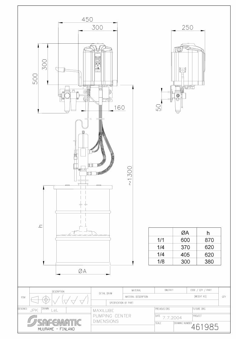
P 150 W Power consumption max m 13 kg Weight See drawing 461985 mm Dimensions
5.2 Connections
Inputs • pressure air, pipe Ø 12 mm or Ø 1/2” • low level switch, connector M12 • pressure control, 2 pcs, connector M12 • power input, PG 13,5 cable gland
Outputs • lubricant, 1 or 2 pcs (line 1 out, line 2 out), pipe Ø 12 mm or Ø 1/2” • pumping center 2 or shut-off valve, 2 pcs, connector M12
Cable channels in the bottom plate • PG 11 cable gland, 4 pcs, for 4-10 mm cable diameters

SAFEGREASE 2 MAXILUBE
MMAX1FEN.doc 11.01.2007 Rev. 1F
8 (9)
5.3 Symbols
MAX-A-B-C-D-E-F Abbreviation
Description
MAX: MAX Maxilube pumping center A: 1 Number of channels, 1 channel 2 Number of channels, 2 channels B: 1 Number of lines, 1-line system 2 Number of lines, 2-line system C: 24 Control voltage 24 V, if external control is used 115 Power input, 115 V
(Control voltage if external control is used) 230 Power input, 230 V
(Control voltage if external control is used) D: IF105 User interface, IF-105 X External control E: R Connections, R-threads U Connections, NPT-threads F: A Following functions are available: LG-ind, spray lubrication
system, Online, control of progressive distributors M SMS-control:
Following functions are available: LG-ind, spray lubrication system, control of progressive distributors, (Online not available)
Example:
Power input, 230 V
User interface, IF-105
Connections, R-threads
Number of lines, 2-line system
Number of channels, 2 channels
Maxilube pumping center
MAX-2-2-230-IF105-R-M
SMS-control
SAFEGREASE 2 MAXILUBE
MMAX1FEN.doc 11.01.2007 Rev. 1F
9 (9)
6 LID SETS
6.1 Maxilube-ECO
See MAX-LIDSET-1/8-ECO-300 lid set assembly (drawing 361190A)
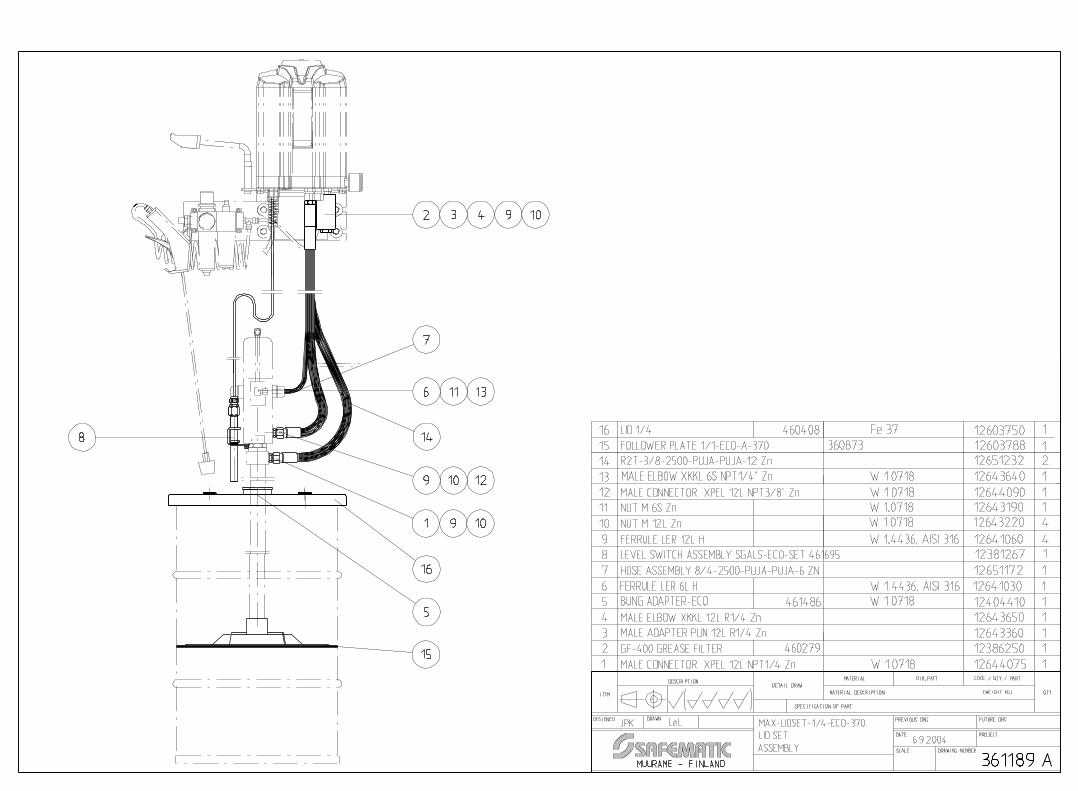
See MAX-LIDSET-1/4-ECO-370 lid set assembly (drawing 361189A)
See MAX-LIDSET-1/1-ECO-590 lid set assembly (drawing 361188A)
6.2 Maxilube-STA
See MAX-LIDSET-1/4-STA-370 lid set assembly (drawing 361191A)
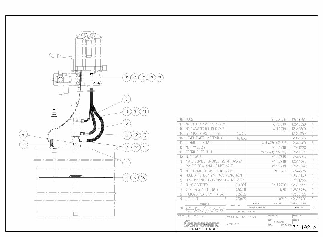
See MAX-LIDSET-1/1-STA-590 lid set assembly (drawing 361192A)
7 SPARE PARTS
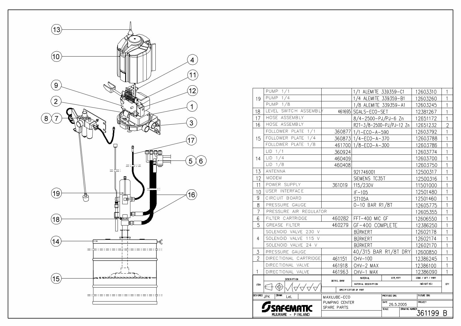
See Maxilube-ECO pumping center spare parts (drawing no. 361199B).
See Maxilube-STA pumping center spare parts (drawing no. 361198B).


1
2 CHV-100
3
BÜRKERT
SIEMENS TC35T
8/4-1600-PJ/PJ-6 Zn
1/4 ALEMITE 339359-B1
1/8 ALEMITE 339359-A1
1
BÜRKERT
BÜRKERT
1/1 ALEMITE 339359-C1
CHV-1 MAX
CHV-2 MAX
SGALS-SET
921746001
DIRECTIONAL VALVE
DIRECTIONAL CARTRIDGE
GREASE FILTER GF-400 COMPLETE
CIRCUIT BOARD
MODEM
ANTENNA
LID 1/1
HOSE ASSEMBLY
LEVEL SWITCH ASSEMBLY
HOSE ASSEMBLY
SOLENOID VALVE 24 V
LID 1/4
DIRECTIONAL VALVE
SPARE PARTS
DESIGNED
ITEM
DESCRIPTIONDETAIL DRAW
MATERIAL DIM,PATT
QTYMATERIAL DESCRIPTION (WEIGHT KG)
SPECIFICATION OF PART
PREVIOUS DRG FUTURE DRG
DATE
SCALE DRAWING NUMBER
DRAWN
PROJECT
MUURAME - FINLAND
CODE / QTY / PART
461963 12386090
461151 12386245
12600850
12602178
460279 12386250
12606550FFT-400 MIC GF
126057750-10 BAR R1/8T
11501000
12500316
12651162
12381265
12603310
12651222R2T-3/8-1600-PJ/PJ-12 Zn
12603260
12603245
461918 12386100
12605355
12602174
12602170
12603750
12603700
1/1-STA-35-565 12802850
1/4-STA-35-355 12802810
1/1-STA-28.5-565 12802840
1/4-STA-28.5-355 12802800
ST105A
IF-105
115/230V
461536
460413
460417
460414
460418
460409
460408
361019
460282
12501460
12501480
1
1
1
1
1
1
1
1
1
1
1
1
1
1
12500317 1
1
1
1
1
2
1
1
1
1
1
4
5
6
7
8
9
10
11
12
13
14
15
16
17
18
19
1
1
MAXILUBE-STAJPK
PUMP 1/1
PUMP 1/4
PUMP 1/8
FOLLOWER PLATE 1/1
FOLLOWER PLATE 1/4
FOLLOWER PLATE 1/1
FOLLOWER PLATE 1/4
POWER SUPPLY
USER INTERFACE
PRESSURE GAUGE
PRESSURE AIR REGULATOR
FILTER CARTRIDGE
SOLENOID VALVE 230 V
SOLENOID VALVE 115 V
40/315 BAR R1/8T DRY
PUMPING CENTER
PRESSURE GAUGE
13
10
78
2
9
19
14
18
15
16
5 617
3
1
12
11
4
LeL
( )
361198 B
15.9.2004