Pump Unit Maple 60-M2 R1 - Carlisle Fluid Technologies · Model 104020-M2 . Instruction Manual Page...
16
Instruction Manual Maple 60/3 Pump Model 104020-M2
Transcript of Pump Unit Maple 60-M2 R1 - Carlisle Fluid Technologies · Model 104020-M2 . Instruction Manual Page...
Instruction Manual Maple 60/3 Pump
Model 104020-M2
Instruction Manual
Page 2 of 16 Issue: 1.0

Instruction Manual
Page 3 of 16 Issue: 1.0
Specification
Pump Ratio 3:1
Max. Air Pressure Inlet 7 Bar
Max. Fluid Pressure 21 Bar
Nominal Flow Volume / Cycle 1.5 Litres
0.4 US Gall
Fluid Output @ 60 cycles/min 90.0 Litres / min
24.0 US Gall / min
Maximum Recommended Continuous Cycle Rate
Maximum Recommended Intermittent Cycle Rate
20 Cycles /min
40 Cycles /min
Fluid Connections
1½” Sanitary
Compressed Air Inlet 1/2” BSPP / NPSM
Air Volume / cycle 0.7 SCFM (9.5 L/m) @ 45PSI (3.1 Bar)
1.4 SCFM (18.5 L/m) @ 90 PSI (6.2 Bar)
Air Flow @ 15 cycles/min 6 bar Air Flow @ 30 cycles/min 6 bar
21 CFM (595 L/min) 42 CFM (1190 L/min)
Max. Pump Inlet Pressure 2 Bar (30 PSI)
Air Quality ISO 8573.1 Class 3.3.2 # (See Note) Dirt 5 microns
Water -20ºC@7bar (940ppm) Oil 0.1mg/m³
Total Weight of Pump 65 Kg / 143 lbs
# Note: Class 3.4.2 Air Quality (Refrigerant dried - water +3ºC@7bar) may be used, however, above 15 cycles/min optional piped exhaust system should be used, if used continuously.
Instruction Manual
Page 4 of 16 Issue: 1.0

Instruction Manual
Page 5 of 16 Issue: 1.0
Instruction Manual
Page 6 of 16 Issue: 1.0
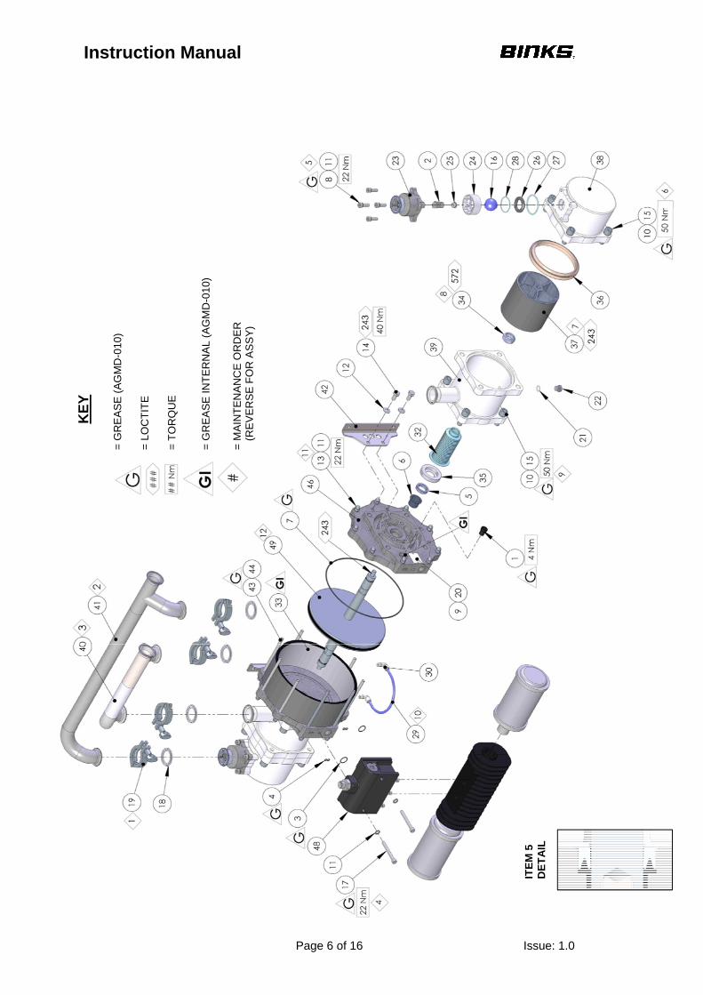
KE
Y
= G
RE
AS
E (
AG
MD
-010
) =
LO
CT
ITE
=
TO
RQ
UE
=
GR
EA
SE
INT
ER
NA
L (A
GM
D-0
10)
= M
AIN
TE
NA
NC
E O
RD
ER
(R
EV
ER
SE
FO
R A
SS
Y)
ITE
M 5
D
ET
AIL
Instruction Manual
Page 7 of 16 Issue: 1.0
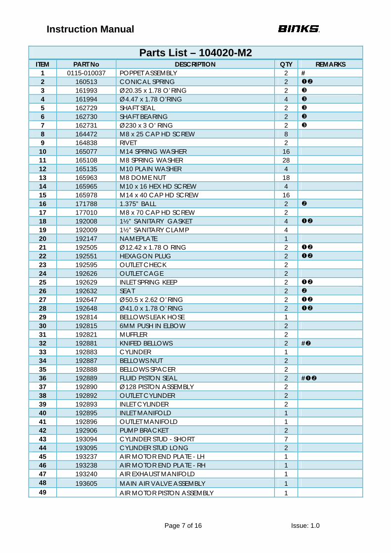
Parts List – 104020-M2 ITEM PART No DESCRIPTION QTY REMARKS
1 0115-010037 POPPET ASSEMBLY 2 # 2 160513 CONICAL SPRING 2 3 161993 Ø20.35 x 1.78 O’RING 2 4 161994 Ø4.47 x 1.78 O'RING 4 5 162729 SHAFT SEAL 2 6 162730 SHAFT BEARING 2 7 162731 Ø230 x 3 O' RING 2 8 164472 M8 x 25 CAP HD SCREW 8 9 164838 RIVET 2
10 165077 M14 SPRING WASHER 16 11 165108 M8 SPRING WASHER 28 12 165135 M10 PLAIN WASHER 4 13 165963 M8 DOME NUT 18 14 165965 M10 x 16 HEX HD SCREW 4 15 165978 M14 x 40 CAP HD SCREW 16 16 171788 1.375” BALL 2 17 177010 M8 x 70 CAP HD SCREW 2 18 192008 1½” SANITARY GASKET 4 19 192009 1½” SANITARY CLAMP 4 20 192147 NAMEPLATE 1 21 192505 Ø12.42 x 1.78 O RING 2 22 192551 HEXAGON PLUG 2 23 192595 OUTLET CHECK 2 24 192626 OUTLET CAGE 2 25 192629 INLET SPRING KEEP 2 26 192632 SEAT 2 27 192647 Ø50.5 x 2.62 O’RING 2 28 192648 Ø41.0 x 1.78 O’RING 2 29 192814 BELLOWS LEAK HOSE 1 30 192815 6MM PUSH IN ELBOW 2 31 192821 MUFFLER 2 32 192881 KNIFED BELLOWS 2 # 33 192883 CYLINDER 1 34 192887 BELLOWS NUT 2 35 192888 BELLOWS SPACER 2 36 192889 FLUID PISTON SEAL 2 # 37 192890 Ø128 PISTON ASSEMBLY 2 38 192892 OUTLET CYLINDER 2 39 192893 INLET CYLINDER 2 40 192895 INLET MANIFOLD 1 41 192896 OUTLET MANIFOLD 1 42 192906 PUMP BRACKET 2 43 193094 CYLINDER STUD - SHORT 7 44 193095 CYLINDER STUD LONG 2 45 193237 AIR MOTOR END PLATE - LH 1 46 193238 AIR MOTOR END PLATE - RH 1 47 193240 AIR EXHAUST MANIFOLD 1 48 193605 MAIN AIR VALVE ASSEMBLY 1 49 AIR MOTOR PISTON ASSEMBLY 1

Instruction Manual
Page 8 of 16 Issue: 1.0
Item 49 – Detail A
ITEM PART No DESCRIPTION QTY REMARKS 50 162728 PISTON SEAL 1 51 165975 M16 x 60 GRUBSCREW STST 1 52 192882 SHAFT 2 53 192886 AIR PISTON 1
= GREASE (AGMD-010) = LOCTITE
= TORQUE
= GREASE INTERNAL (AGMD-010)
= MAINTENANCE ORDER (REVERSE FOR ASSY)
KEY

Instruction Manual
Page 9 of 16 Issue: 1.0
Item 35 – 192890 Piston Assembly
ITEM PART No DESCRIPTION QTY REMARKS 60 160513 CONICAL SPRING 1 61 163920 M6 x 30 CAP HD SCREW 5 62 171784 1¾” BALL 1 63 192629 INLET SPRING KEEP 1 64 192631 PISTON INLET SEAT 1 65 192646 Ø50.5 x 1.78 O’RING 1 66 192891 Ø128 PISTON 1 67 192894 Ø128 PISTON KEEP PLATE 1
= LOCTITE = TORQUE
KEY
Instruction Manual
Page 10 of 16 Issue: 1.0
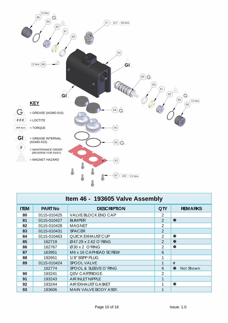
Item 46 - 193605 Valve Assembly
ITEM PART No DESCRIPTION QTY REMARKS 80 0115-010425 VALVE BLOCK END CAP 2 81 0115-010427 BUMPER 2 82 0115-010428 MAGNET 2 83 0115-010431 SPACER 2 84 0115-010463 QUICK EXHAUST CUP 2 85 162719 Ø47.29 x 2.62 O’RING 2 86 162767 Ø30 x 2 O'RING 2 87 163951 M6 x 16 CAPHEAD SCREW 6 88 192651 1/8" BSPP PLUG 1 89 0115-010424 SPOOL VALVE 1 #
162774 SPOOL & SLEEVE O’RING 6 Not Shown 90 193241 QEV CARTRIDGE 2 91 193243 AIR INLET NIPPLE 1 92 193244 AIR EXHAUST GASKET 1 93 193606 MAIN VALVE BODY ASSY. 1
= GREASE (AGMD-010)
= LOCTITE
= TORQUE = GREASE INTERNAL (AGMD-010)
= MAINTENANCE ORDER (REVERSE FOR ASSY)
= MAGNET HAZARD
KEY

Instruction Manual
Page 11 of 16 Issue: 1.0
Fault Finding
Symptom Possible Cause Remedy
Pump will not ‘Prime’
a. Air getting into the suction hose/manifold
b. Worn piston seals c. Ball checks not seating correctly
a. Check seals and hose connections b. Replace piston seals c. Inspect, clean/replace balls/seats
Pump will not run a. No Air or Fluid supply
b. Air piston seal worn.
c. Pilot valve assemblies inoperable.
d. Main air valve inoperable e. QE diaphragm defective
f. Ball checks not seating
a. Check air and fluid supply ball valves and supply hoses.
b. Replace Piston seal c. Switch/interchange pilot valves to
isolate faulty pilot valve and clean/replace.
d. Check clean/replace Air valve. e. Check for constant exhaust air when
pump is not running. Check/replace QE diaphragms
f. Inspect, clean and/or replace balls and seats.
Pump runs but has excessive pulsation
a. Air getting into fluid line, air supply restricted.
b. Obstructed fluid ball checks.
c. Worn air motor piston seals. d. Worn/failed air motor shaft seals. e. Worn fluid piston seal. f. Air exhaust restricted.
a. Check seals and hose connections. Check air supply
b. Remove, clean, and inspect seat, ball, and ball cage. Replace if suspect or worn.
c. Replace air motor piston seal. d. Disassemble pump as required to
replace air motor shaft seals. e. Replace fluid piston seal. f. Check QE diaphragms and exhaust
outlets.
Paint leaking into detection hose (27) Air bleeding from Endcaps (43 &44).
a. Bellows seal failure b. Air motor shaft seal leaking.
a. Replace bellows seal (30) b. Check air motor shaft seal (5),
replace as necessary
Instruction Manual
Page 12 of 16 Issue: 1.0
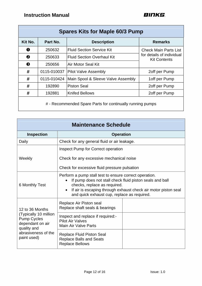
Maintenance Schedule
Inspection Operation
Daily Check for any general fluid or air leakage.
Weekly
Inspect Pump for Correct operation Check for any excessive mechanical noise Check for excessive fluid pressure pulsation
6 Monthly Test
Perform a pump stall test to ensure correct operation. • If pump does not stall check fluid piston seals and ball
checks, replace as required. • If air is escaping through exhaust check air motor piston seal
and quick exhaust cup, replace as required.
12 to 36 Months (Typically 10 million Pump Cycles dependant on air quality and abrasiveness of the paint used)
Replace Air Piston seal Replace shaft seals & bearings
Inspect and replace if required:- Pilot Air Valves Main Air Valve Parts
Replace Fluid Piston Seal Replace Balls and Seats Replace Bellows
Spares Kits for Maple 60/3 Pump
Kit No. Part No. Description Remarks
250632 Fluid Section Service Kit Check Main Parts List for details of individual
Kit Contents
250633 Fluid Section Overhaul Kit
250656 Air Motor Seal Kit
# 0115-010037 Pilot Valve Assembly 2off per Pump
# 0115-010424 Main Spool & Sleeve Valve Assembly 1off per Pump
# 192890 Piston Seal 2off per Pump
# 192881 Knifed Bellows 2off per Pump
# - Recommended Spare Parts for continually running pumps
Instruction Manual
Page 13 of 16 Issue: 1.0
Installation This product should be flushed with a suitable compatible solvent prior to use.
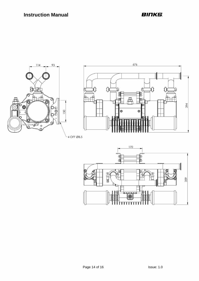
Mount the pump securely and position the pump at a convenient height (below the lid height of the paint container), to allow for maintenance, visual observation, and periodic inspection. The wall mount bracket is included with all pumps.
The Pump Mounting bracket must be connected to a suitable earth ground to ensure that there is no possibility of static build up. Attach suitable flexible hoses to the inlet and outlet connections. Connect a suitable 3/8” – ½” NB air hose and ½” Pressure Filter Regulator to the air motor. (Filter rated at minimum 1000 L/min)
No additional air lubrication is required as piston ring lubricant is applied during assembly or repair. If an air lubricator is used then this must be maintained.
Set the pump speed to a slow cycle rate and start the pump to remove any air from the fluid circuit before increasing pressure. Inspect for any air or fluid leaks.
If an air blow out system is used, never exceed 2 Bar on the inlet of the pump.
Exhaust kits are available for these pumps if the air exhaust is required to be piped away from the pump rather than exhausting locally through the mufflers.
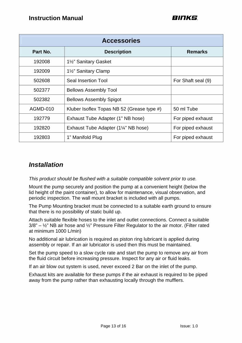
Accessories
Part No. Description Remarks
192008 1½” Sanitary Gasket
192009 1½” Sanitary Clamp
502608 Seal Insertion Tool For Shaft seal (9)
502377 Bellows Assembly Tool
502382 Bellows Assembly Spigot
AGMD-010 Kluber Isoflex Topas NB 52 (Grease type #) 50 ml Tube
192779 Exhaust Tube Adapter (1” NB hose) For piped exhaust
192820 Exhaust Tube Adapter (1¼” NB hose) For piped exhaust
192803 1” Manifold Plug For piped exhaust
Instruction Manual
Page 14 of 16 Issue: 1.0

Instruction Manual
Page 15 of 16 Issue: 1.0
Instruction Manual
Page 16 of 16 Issue: 1.0
Justus-von-Liebig-Straße 31, 63128 Dietzenbach. DE Tel. +49 (0) 6074 403 1 Fax. +49 (0) 607 403 300 General e-mail: [email protected]
163-171, Av. des Auréats, 26014 Valence cedex. FR Téléphone : +33 (0) 4 75 75 27 53 Télécopie: +33 (0) 4 75 75 27 79 General e-mail: [email protected] USA Canada Customer Service 195 Internationale Blvd. Glendale Height,IL 60139 630-237-5000 Toll Free Customer Service and Technical Support 800-992-4657 Toll Free Facsimile 800-246-5732
Binks registered office Finishing Brands Germany GmbH Justus-von-Liebig-Straße 31, 63128 Dietzenbach. Amtsgericht Offenbach HRB 43560
Ringwood Road, Bournemouth, Dorset BH11 9LH. UK Tel. +44 (0)1202 571 111 Fax. +44 (0)1202 573 488 General e-mail: [email protected]