Pump Hydraulics Rev 02 -...
22
KLM Technology Group Practical Engineering Guidelines for Processing Plant Solutions Solutions, Standards and Software www.klmtechgroup.com Page : 1 of 80 Rev: 04 Rev 01 Feb 2007 Rev 02 Feb 2009 Rev 03 May 2012 Rev 04 Mar 2014 KLM Technology Group #03-12 Block Aronia, Jalan Sri Perkasa 2 Taman Tampoi Utama 81200 Johor Bahru Malaysia Pump Hydraulics Sizing and Selection (ENGINEERING DESIGN GUIDELINE) Co Authors Rev 01 - A L Ling Rev 02 - Viska Mulyandasari Rev 03 - K Kolmetz Rev 04 - Reni Mutiara Sari Editor / Author Karl Kolmetz TABLE OF CONTENT INTRODUCTION Scope 6 General Design Consideration 7 Type of Pump 7 A. Positive Displacement Pumps 7 a) Reciprocating Pump 7 b) Rotary Pump 8 B. Dynamic Pumps 8 a) Centrifugal Pumps 8 KLM Technology Group has developed; 1) Process Engineering Equipment Design Guidelines, 2) Equipment Design Software, 3) Project Engineering Standards and Specifications, and 4) Unit Operations Manuals. Each has many hours of engineering development. KLM is providing the introduction to this guideline for free on the internet. Please go to our website to order the complete document. www.klmtechgroup.com
Transcript of Pump Hydraulics Rev 02 -...

KLM Technology
Group
Practical Engineering Guidelines for Processing
Plant Solutions
Solutions, Standards and Software
www.klmtechgroup.com
Page : 1 of 80
Rev: 04
Rev 01 Feb 2007 Rev 02 Feb 2009 Rev 03 May 2012 Rev 04 Mar 2014
KLM Technology Group #03-12 Block Aronia, Jalan Sri Perkasa 2 Taman Tampoi Utama 81200 Johor Bahru Malaysia
Pump Hydraulics Sizing and Selection
(ENGINEERING DESIGN GUIDELINE)
Co Authors Rev 01 - A L Ling Rev 02 - Viska Mulyandasari Rev 03 - K Kolmetz Rev 04 - Reni Mutiara Sari Editor / Author
Karl Kolmetz
TABLE OF CONTENT INTRODUCTION
Scope 6 General Design Consideration 7
Type of Pump 7
A. Positive Displacement Pumps 7
a) Reciprocating Pump 7 b) Rotary Pump 8
B. Dynamic Pumps 8
a) Centrifugal Pumps 8
KLM Technology Group has developed; 1) Process Engineering Equipment Design Guidelines, 2) Equipment Design Software, 3) Project Engineering Standards and Specifications, and 4) Unit Operations Manuals. Each has many hours of engineering development. KLM is providing the introduction to this guideline for free on the internet. Please go to our website to order the complete document.
www.klmtechgroup.com

KLM Technology Group
Practical Engineering
Guidelines for Processing Plant Solutions
Pump Hydraulics Selection and Sizing
(ENGINEERING DESIGN GUIDELINE)
Page 2 of 80
Rev: 04
March 2014
These design guideline are believed to be as accurate as possible, but are very general and not for specific design cases. They were designed for engineers to do preliminary designs and process specification sheets. The final design must always be guaranteed for the service selected by the manufacturing vendor, but these guidelines will greatly reduce the amount of up front engineering hours that are required to develop the final design. The guidelines are a training tool for young engineers or a resource for engineers with experience. This document is entrusted to the recipient personally, but the copyright remains with us. It must not be copied, reproduced or in any way communicated or made accessible to third parties without our written consent.
Process Requirements Parameters 11
DEFINITIONS 13 NOMENCLATURE 16
Greek letters 17 THEORY 18
Working Principle of Pump 18
I. Centrifugal Pump 18
A) Component of Centrifugal Pumps 19 I) Rotating Elements 20 II) Stationary Elements 22
B) Centrifugal Pump Characteristics 25
a) Centrifugal Pump Curve Characteristics 25 b) Specific Speed 27 c) Suction Specific Speed 28 d) Affinity Laws 28 e) Temperature Rise Due to Pumping 30
C) Working Theory-Conversion of Kinetic Energy to Pressure Energy 30
II. Positive Displacement Pump 31
A) Reciprocating Pumps 31
a) Pump Calculation 32 b) Pulsation 34
KLM Technology Group
Practical Engineering
Guidelines for Processing Plant Solutions
Pump Hydraulics Selection and Sizing
(ENGINEERING DESIGN GUIDELINE)
Page 3 of 80
Rev: 04
March 2014
These design guideline are believed to be as accurate as possible, but are very general and not for specific design cases. They were designed for engineers to do preliminary designs and process specification sheets. The final design must always be guaranteed for the service selected by the manufacturing vendor, but these guidelines will greatly reduce the amount of up front engineering hours that are required to develop the final design. The guidelines are a training tool for young engineers or a resource for engineers with experience. This document is entrusted to the recipient personally, but the copyright remains with us. It must not be copied, reproduced or in any way communicated or made accessible to third parties without our written consent.
B) Rotary Pumps 35
Pump Selection 36
I. Industry Codes and Standards for Pump Selection & Design 40
Total Head 41
Net Positive Suction Head – NPSH 43
Pump Power and Efficiency 46
I) Power 46 II) Pump Efficiency 47
Multiple Pumps Installation 48
Cavitation 49
Pump Sizing- Step by Step Calculation 50
Troubleshooting of The Pump Problems 52
Material of Construction 58
APPLICATION 61
Example Case 1: Pump Sizing for water flow 61 Example Case 2: Pump Sizing for Hydrocarbon flow 66 Example Case 3: Pump Sizing for Slurry flow 72
REFEREENCES 78

KLM Technology Group
Practical Engineering
Guidelines for Processing Plant Solutions
Pump Hydraulics Selection and Sizing
(ENGINEERING DESIGN GUIDELINE)
Page 4 of 80
Rev: 04
March 2014
These design guideline are believed to be as accurate as possible, but are very general and not for specific design cases. They were designed for engineers to do preliminary designs and process specification sheets. The final design must always be guaranteed for the service selected by the manufacturing vendor, but these guidelines will greatly reduce the amount of up front engineering hours that are required to develop the final design. The guidelines are a training tool for young engineers or a resource for engineers with experience. This document is entrusted to the recipient personally, but the copyright remains with us. It must not be copied, reproduced or in any way communicated or made accessible to third parties without our written consent.
LIST OF TABLE
Table 1: Seal for centrifugal pumps 25 Table 2: Typical speed of rotation for centrifugal pump 27 Table 3: Affinity Laws 29 Table 4: General selection methods for centrifugal pumps 36 Table 5: General selection method for positive displacement pumps 38 Tabel 6 : General Centrifugal Pump Problem and Solution 54 Table 7: Pump Material of Construction for specific services 60
LIST OF FIGURE
Figure 1: Foot mounted overhung pump 9 Figure 2: Centerline mounted overhung pump 9 Figure 3 : Radically split multistage-single & double casing 9 Figure 4: Simple Centrifugal Pump 18 Figure 5 : Seven-stage centrifugal pump 19 Figure 6 : component of centrifugal pump 20 Figure 7 : Some types of impellers for centrifugal pumps 21 Figure 8 : Type of casings 22 Figure 9 : Type of Seal 23 Figure 10 : Performance Curve of Centrifugal Pumps 26 Figure 11 : Specific speed variations of different types of pump 28 Figure 12 : double-acting piston pump 32

KLM Technology Group
Practical Engineering
Guidelines for Processing Plant Solutions
Pump Hydraulics Selection and Sizing
(ENGINEERING DESIGN GUIDELINE)
Page 5 of 80
Rev: 04
March 2014
These design guideline are believed to be as accurate as possible, but are very general and not for specific design cases. They were designed for engineers to do preliminary designs and process specification sheets. The final design must always be guaranteed for the service selected by the manufacturing vendor, but these guidelines will greatly reduce the amount of up front engineering hours that are required to develop the final design. The guidelines are a training tool for young engineers or a resource for engineers with experience. This document is entrusted to the recipient personally, but the copyright remains with us. It must not be copied, reproduced or in any way communicated or made accessible to third parties without our written consent.
Figure 13 : Positive-displacement gear-type rotary pump 35 Figure 14 : Selection guides for various type of pumps 41 Figure 15 : Centrifugal Pump Efficiency 48 Figure 16 : Pump Installation 49

KLM Technology Group
Practical Engineering
Guidelines for Processing Plant Solutions
Pump Hydraulics Selection and Sizing
(ENGINEERING DESIGN GUIDELINE)
Page 6 of 80
Rev: 04
March 2014
These design guideline are believed to be as accurate as possible, but are very general and not for specific design cases. They were designed for engineers to do preliminary designs and process specification sheets. The final design must always be guaranteed for the service selected by the manufacturing vendor, but these guidelines will greatly reduce the amount of up front engineering hours that are required to develop the final design. The guidelines are a training tool for young engineers or a resource for engineers with experience. This document is entrusted to the recipient personally, but the copyright remains with us. It must not be copied, reproduced or in any way communicated or made accessible to third parties without our written consent.
KLM Technology Group is providing the introduction to this guideline for free on the internet. Please go to our website to order the complete document.
www.klmtechgroup.com
INTRODUCTION Scope
This design guideline assists engineers, maintenance and operations personnel to understand the selection and sizing of pumps. A pump is one of the most important pieces of mechanical equipment that is present in industrial processes. A pump moves liquid from one area to another by increasing the pressure of the liquid above the amount needed to overcome the combined effects of friction, gravity and system operating pressures.
There are two types of pump which are generally used in industrial processes: positive displacement pump and centrifugal. It is important to choose the suitable type of pump based on process requirement and fluid process properties. The functions and types of pump are explained in detail under the General Design Guideline section. The theory section covers the selection method of the pump based on their application and engineering calculations for the sizing of the pump. When sizing the pump, the understanding of concept of cavitation is very important. Cavitation is an abnormal condition that can result in loss of production, equipment damage and worst of all, personnel injury. To prevent pumps from having this problem, the correct design should be followed by applied the correct theory when carrying out the activities of pump sizing and selection.
In the application section of this guideline, three case studies are shown and discussed in detail, highlighting the way to apply the theory for the calculation. Generally used theory, such as Bernoulli’s theory, is used as the basic of calculation because it is applicable for various conditions. This theory is applied in calculation of the NPSH of the pumps, which is shown in detail in this section. The case studies will help the engineer do the selection and sizing for the pumps base on their own plant system.

KLM Technology Group
Practical Engineering
Guidelines for Processing Plant Solutions
Pump Hydraulics Selection and Sizing
(ENGINEERING DESIGN GUIDELINE)
Page 7 of 80
Rev: 04
March 2014
These design guideline are believed to be as accurate as possible, but are very general and not for specific design cases. They were designed for engineers to do preliminary designs and process specification sheets. The final design must always be guaranteed for the service selected by the manufacturing vendor, but these guidelines will greatly reduce the amount of up front engineering hours that are required to develop the final design. The guidelines are a training tool for young engineers or a resource for engineers with experience. This document is entrusted to the recipient personally, but the copyright remains with us. It must not be copied, reproduced or in any way communicated or made accessible to third parties without our written consent.
INTRODUCTION General Design Consideration
Type of Pump The selection of type and construction of a pump is very important to meet the process specification and proper application. Knowledge of the variety of pumps in the market should be reviewed and understood. A. Positive Displacement Pumps
Positive displacement (PD) pumps work by allowing a fluid to flow into some enclosed cavity from a low-pressure source, trapping the fluid, and then forcing it out into a high-pressure receiver by decreasing the volume of the cavity. This is done intermittently in the case of reciprocating pumps and continuously in the case of rotary gear and screw pumps. Some examples of PD pumps are: fuel and oil pumps in most automobiles, the pumps on most hydraulic systems, and the heart of most animals. Some general types of the positive displacement pumps are as below:
a) Reciprocating Pump
Reciprocating pumps create and displace a volume of liquid, their “displacement volumes”, by action of a reciprocating element. Liquid discharge pressure is limited only by strength of structural parts. A pressure relief valve and a discharge check valve are normally required for reciprocating pumps. Reciprocating pumps can be further classified into three types of pump as below,
i) Piston Pumps ii) Packed Plunger Pumps iii) Diaphragm Pumps

KLM Technology Group
Practical Engineering
Guidelines for Processing Plant Solutions
Pump Hydraulics Selection and Sizing
(ENGINEERING DESIGN GUIDELINE)
Page 8 of 80
Rev: 04
March 2014
These design guideline are believed to be as accurate as possible, but are very general and not for specific design cases. They were designed for engineers to do preliminary designs and process specification sheets. The final design must always be guaranteed for the service selected by the manufacturing vendor, but these guidelines will greatly reduce the amount of up front engineering hours that are required to develop the final design. The guidelines are a training tool for young engineers or a resource for engineers with experience. This document is entrusted to the recipient personally, but the copyright remains with us. It must not be copied, reproduced or in any way communicated or made accessible to third parties without our written consent.
b) Rotary Pump
Rotary pumps function with close clearances such that a fixed volume of liquid is displaced with each revolution of the internal element. Rotary pumps include:
i) Gear Pump ii) Lobe Pump iii) Vane Pump iv) Screw Pump
All those pumps above have the similar working principles: pumping the liquid with the help of rotating elements. The difference lies on the rotating elements; they could be gear, lobe, vane, or screw.
B. Dynamic Pumps Dynamic pumps, in which energy is continuously added to increase the fluid velocities within the machines to values greater than those occurring at the discharge so subsequent velocity reduction within or beyond the pump produces a pressure increase. Major kinds which often used in many industries are centrifugal pumps[8].
a) Centrifugal Pumps
Centrifugal pumps are dynamic pumps. A centrifugal pump raises the pressure of the liquid by giving it a high kinetic energy and then converts it into pressure energy before the fluid exits the pump. It normally consists of an impeller (a wheel with blades), and some form of housing with a central inlet and a peripheral outlet. The impeller is mounted on a rotating shaft and enclosed in a stationary casing. Casings are generally of two types: volute and circular. The impeller design and the shape of the casing determine how liquid is accelerated though the pump.

KLM Technology Group
Practical Engineering
Guidelines for Processing Plant Solutions
Pump Hydraulics Selection and Sizing
(ENGINEERING DESIGN GUIDELINE)
Page 9 of 80
Rev: 04
March 2014
These design guideline are believed to be as accurate as possible, but are very general and not for specific design cases. They were designed for engineers to do preliminary designs and process specification sheets. The final design must always be guaranteed for the service selected by the manufacturing vendor, but these guidelines will greatly reduce the amount of up front engineering hours that are required to develop the final design. The guidelines are a training tool for young engineers or a resource for engineers with experience. This document is entrusted to the recipient personally, but the copyright remains with us. It must not be copied, reproduced or in any way communicated or made accessible to third parties without our written consent.
Some general types of the centrifugal pumps are as below:
i) Overhung pump
A pump with the impeller(s) cantilevered from its bearing assemblies is classified as an overhung pump.
ii) Between bearings pump
A pump with the impeller(s) located between the bearings is classified as a between bearings pump. The pump may be single-stage (one impeller), two-stage, or multistage. It can be axially (horizontally) split or radially split.
Figure 3: Radically split multistage-single & double casing.
Figure 1: Foot mounted overhung pump
Figure 2: Centerline mounted overhung pump
KLM Technology Group
Practical Engineering
Guidelines for Processing Plant Solutions
Pump Hydraulics Selection and Sizing
(ENGINEERING DESIGN GUIDELINE)
Page 10 of 80
Rev: 04
March 2014
These design guideline are believed to be as accurate as possible, but are very general and not for specific design cases. They were designed for engineers to do preliminary designs and process specification sheets. The final design must always be guaranteed for the service selected by the manufacturing vendor, but these guidelines will greatly reduce the amount of up front engineering hours that are required to develop the final design. The guidelines are a training tool for young engineers or a resource for engineers with experience. This document is entrusted to the recipient personally, but the copyright remains with us. It must not be copied, reproduced or in any way communicated or made accessible to third parties without our written consent.
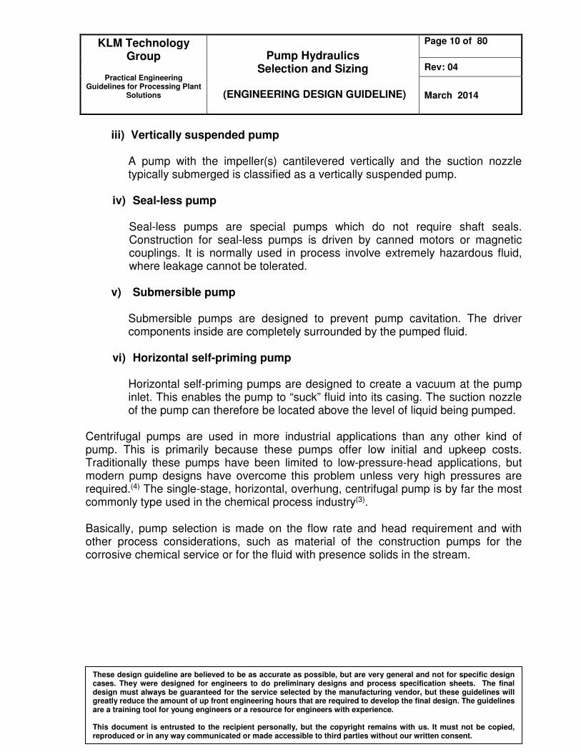
iii) Vertically suspended pump
A pump with the impeller(s) cantilevered vertically and the suction nozzle typically submerged is classified as a vertically suspended pump.
iv) Seal-less pump
Seal-less pumps are special pumps which do not require shaft seals. Construction for seal-less pumps is driven by canned motors or magnetic couplings. It is normally used in process involve extremely hazardous fluid, where leakage cannot be tolerated.
v) Submersible pump
Submersible pumps are designed to prevent pump cavitation. The driver components inside are completely surrounded by the pumped fluid.
vi) Horizontal self-priming pump
Horizontal self-priming pumps are designed to create a vacuum at the pump inlet. This enables the pump to “suck” fluid into its casing. The suction nozzle of the pump can therefore be located above the level of liquid being pumped.
Centrifugal pumps are used in more industrial applications than any other kind of pump. This is primarily because these pumps offer low initial and upkeep costs. Traditionally these pumps have been limited to low-pressure-head applications, but modern pump designs have overcome this problem unless very high pressures are required.(4) The single-stage, horizontal, overhung, centrifugal pump is by far the most commonly type used in the chemical process industry(3).
Basically, pump selection is made on the flow rate and head requirement and with other process considerations, such as material of the construction pumps for the corrosive chemical service or for the fluid with presence solids in the stream.

KLM Technology Group
Practical Engineering
Guidelines for Processing Plant Solutions
Pump Hydraulics Selection and Sizing
(ENGINEERING DESIGN GUIDELINE)
Page 11 of 80
Rev: 04
March 2014
These design guideline are believed to be as accurate as possible, but are very general and not for specific design cases. They were designed for engineers to do preliminary designs and process specification sheets. The final design must always be guaranteed for the service selected by the manufacturing vendor, but these guidelines will greatly reduce the amount of up front engineering hours that are required to develop the final design. The guidelines are a training tool for young engineers or a resource for engineers with experience. This document is entrusted to the recipient personally, but the copyright remains with us. It must not be copied, reproduced or in any way communicated or made accessible to third parties without our written consent.
Process Requirements Parameters In designing the pump, the knowledge of the effect of parameters; such as pump capacity, NPSH, pumping maximum temperature, specific gravity, fluid viscosity, fluid solid content, and the other process requirements are very important. All of these parameters will affect the selection and design of the pump which will affect the performance of the pump in the process. Pump capacity is a parameter plays an important role when selecting the pump. Capacity means the flow rate with which liquid is moved or pushed by the pump to the desired point in the process. It is commonly measured in either gallons per minute (gal/min) or cubic meters per hour (m3/hr). The capacity usually changes with the changes in operation of the process. A minimum required flow rate need to be specified, this is important to determining if a minimum flow bypass is required for the selected pump to avoid pump overheating and mechanical damage. NPSH as a measure to prevent liquid vaporization or called cavitation of pump. Net Positive Suction Head (NPSH) is the total head at the suction flange of the pump less the vapor pressure converted to fluid column height of the liquid. The design engineer should always remember that pumps can pump only liquids, not vapors because when a liquid vaporizes its volume increases greatly. For example: 1ft3 of water it will vaporize to produce 1700ft3 of steam. This will cause the rise in temperature and pressure drop in the fluid and pump will stop functioning because it has not sufficient suction pressure present. Pumping maximum temperatures is important in deciding pump construction style and pump cooling and mechanical seal requirements. The minimum operating temperature is to ensure that the material has adequate impact strength. Specific gravity is parameter determines the pump head required to produce a desired pressure increase. For pumps with limited head capability such as centrifugal pumps, it affects pressure rise capability. Pump power requirements are also affected by specific gravity. Viscosity is important in the selection of pump type and has a significant effect on centrifugal pump performance. Minimum values of viscosity are important in determining rotary pump (positive displacement pump) performance, while maximum viscosity is important in determining debits to centrifugal pump performance.

KLM Technology Group
Practical Engineering
Guidelines for Processing Plant Solutions
Pump Hydraulics Selection and Sizing
(ENGINEERING DESIGN GUIDELINE)
Page 12 of 80
Rev: 04
March 2014
These design guideline are believed to be as accurate as possible, but are very general and not for specific design cases. They were designed for engineers to do preliminary designs and process specification sheets. The final design must always be guaranteed for the service selected by the manufacturing vendor, but these guidelines will greatly reduce the amount of up front engineering hours that are required to develop the final design. The guidelines are a training tool for young engineers or a resource for engineers with experience. This document is entrusted to the recipient personally, but the copyright remains with us. It must not be copied, reproduced or in any way communicated or made accessible to third parties without our written consent.
Fluid solid content will affect the pump design. It affected the aspects of the design for the flow characteristic, consideration design of erosion resistance, flow passage size, impeller style, peripheral speed, design features to disintegrate large particles, and shaft sealing design. This parameter has to be added in the data sheet for design. Other process requirement such as flexibility for expansion should be consider as well. This is important for future capacity expansion; it helps to minimize the cost of expansion because to replace the pump will be a large sum of money. Working capacity of pump should always be design for more than 20% extra design capacity.
KLM Technology Group
Practical Engineering
Guidelines for Processing Plant Solutions
Pump Hydraulics Selection and Sizing
(ENGINEERING DESIGN GUIDELINE)
Page 13 of 80
Rev: 04
March 2014
These design guideline are believed to be as accurate as possible, but are very general and not for specific design cases. They were designed for engineers to do preliminary designs and process specification sheets. The final design must always be guaranteed for the service selected by the manufacturing vendor, but these guidelines will greatly reduce the amount of up front engineering hours that are required to develop the final design. The guidelines are a training tool for young engineers or a resource for engineers with experience. This document is entrusted to the recipient personally, but the copyright remains with us. It must not be copied, reproduced or in any way communicated or made accessible to third parties without our written consent.
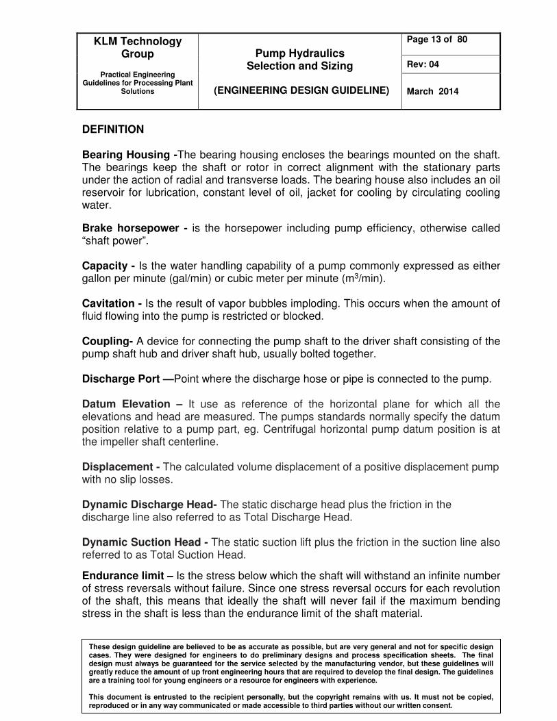
DEFINITION
Bearing Housing -The bearing housing encloses the bearings mounted on the shaft. The bearings keep the shaft or rotor in correct alignment with the stationary parts under the action of radial and transverse loads. The bearing house also includes an oil reservoir for lubrication, constant level of oil, jacket for cooling by circulating cooling water.
Brake horsepower - is the horsepower including pump efficiency, otherwise called “shaft power”. Capacity - Is the water handling capability of a pump commonly expressed as either gallon per minute (gal/min) or cubic meter per minute (m3/min). Cavitation - Is the result of vapor bubbles imploding. This occurs when the amount of fluid flowing into the pump is restricted or blocked. Coupling- A device for connecting the pump shaft to the driver shaft consisting of the pump shaft hub and driver shaft hub, usually bolted together. Discharge Port —Point where the discharge hose or pipe is connected to the pump. Datum Elevation – It use as reference of the horizontal plane for which all the elevations and head are measured. The pumps standards normally specify the datum position relative to a pump part, eg. Centrifugal horizontal pump datum position is at the impeller shaft centerline. Displacement - The calculated volume displacement of a positive displacement pump with no slip losses. Dynamic Discharge Head- The static discharge head plus the friction in the discharge line also referred to as Total Discharge Head. Dynamic Suction Head - The static suction lift plus the friction in the suction line also referred to as Total Suction Head.
Endurance limit – Is the stress below which the shaft will withstand an infinite number of stress reversals without failure. Since one stress reversal occurs for each revolution of the shaft, this means that ideally the shaft will never fail if the maximum bending stress in the shaft is less than the endurance limit of the shaft material.
KLM Technology Group
Practical Engineering
Guidelines for Processing Plant Solutions
Pump Hydraulics Selection and Sizing
(ENGINEERING DESIGN GUIDELINE)
Page 14 of 80
Rev: 04
March 2014
These design guideline are believed to be as accurate as possible, but are very general and not for specific design cases. They were designed for engineers to do preliminary designs and process specification sheets. The final design must always be guaranteed for the service selected by the manufacturing vendor, but these guidelines will greatly reduce the amount of up front engineering hours that are required to develop the final design. The guidelines are a training tool for young engineers or a resource for engineers with experience. This document is entrusted to the recipient personally, but the copyright remains with us. It must not be copied, reproduced or in any way communicated or made accessible to third parties without our written consent.
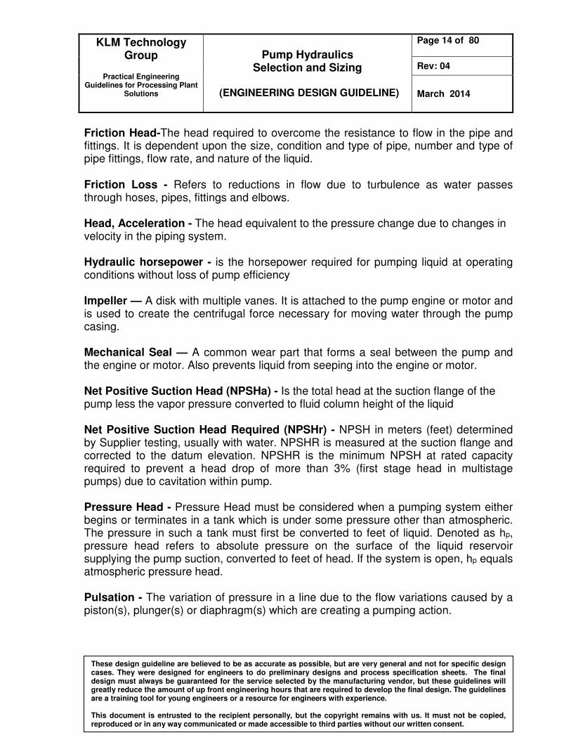
Friction Head-The head required to overcome the resistance to flow in the pipe and fittings. It is dependent upon the size, condition and type of pipe, number and type of pipe fittings, flow rate, and nature of the liquid.
Friction Loss - Refers to reductions in flow due to turbulence as water passes through hoses, pipes, fittings and elbows. Head, Acceleration - The head equivalent to the pressure change due to changes in velocity in the piping system. Hydraulic horsepower - is the horsepower required for pumping liquid at operating conditions without loss of pump efficiency Impeller — A disk with multiple vanes. It is attached to the pump engine or motor and is used to create the centrifugal force necessary for moving water through the pump casing. Mechanical Seal — A common wear part that forms a seal between the pump and the engine or motor. Also prevents liquid from seeping into the engine or motor. Net Positive Suction Head (NPSHa) - Is the total head at the suction flange of the pump less the vapor pressure converted to fluid column height of the liquid
Net Positive Suction Head Required (NPSHr) - NPSH in meters (feet) determined by Supplier testing, usually with water. NPSHR is measured at the suction flange and corrected to the datum elevation. NPSHR is the minimum NPSH at rated capacity required to prevent a head drop of more than 3% (first stage head in multistage pumps) due to cavitation within pump. Pressure Head - Pressure Head must be considered when a pumping system either begins or terminates in a tank which is under some pressure other than atmospheric. The pressure in such a tank must first be converted to feet of liquid. Denoted as hp, pressure head refers to absolute pressure on the surface of the liquid reservoir supplying the pump suction, converted to feet of head. If the system is open, hp equals atmospheric pressure head.
Pulsation - The variation of pressure in a line due to the flow variations caused by a piston(s), plunger(s) or diaphragm(s) which are creating a pumping action.
KLM Technology Group
Practical Engineering
Guidelines for Processing Plant Solutions
Pump Hydraulics Selection and Sizing
(ENGINEERING DESIGN GUIDELINE)
Page 15 of 80
Rev: 04
March 2014
These design guideline are believed to be as accurate as possible, but are very general and not for specific design cases. They were designed for engineers to do preliminary designs and process specification sheets. The final design must always be guaranteed for the service selected by the manufacturing vendor, but these guidelines will greatly reduce the amount of up front engineering hours that are required to develop the final design. The guidelines are a training tool for young engineers or a resource for engineers with experience. This document is entrusted to the recipient personally, but the copyright remains with us. It must not be copied, reproduced or in any way communicated or made accessible to third parties without our written consent.
Slip - Leakage flow within a rotary positive displacement pump from the discharge back to the suction caused by the clearances needed between rotating and stationary components. Suction Specific Speed - An index of pump suction operating characteristics determined at the best efficiency point with the maximum-diameter impeller. Static Suction Head -Head resulting from elevation of the liquid relative to the pump center line (datum). If the liquid level is above pump centerline (datum), hS is positive. If the liquid level is below pump centerline (datum), hS is negative. Negative hS condition is commonly denoted as a “suction lift” condition Static Discharge Head - It is the vertical distance in feet between the pump centerline and the point of free discharge or the surface of the liquid in the discharge tank. Suction Port — Point where the suction hose or pipe is connected to the pump. Vapor Pressure Head - Vapor pressure is the absolute pressure at which a liquid and its vapor co-exist in equilibrium at a given temperature. The vapor pressure of liquid can be obtained from vapor pressure tables. When the vapor pressure is converted to head, it is referred to as vapor pressure head, hvp. The value of hvp of a liquid increases with the rising temperature and in effect, opposes the pressure on the liquid surface, the positive force that tends to cause liquid flow into the pump suction i.e. it reduces the suction pressure head. (Vapor pressure can be said as the external pressure require to prevent fluid from evaporate become vapor). Velocity Head - Refers to the energy of a liquid as a result of its motion at some velocity ‘v’. It is the equivalent head in feet through which the water would have to fall to acquire the same velocity, or in other words, the head necessary to accelerate the water. The velocity head is usually insignificant and can be ignored in most high head systems. However, it can be a large factor and must be considered in low head systems. Viscosity — is a mechanist of fluid resistance to flow of a liquid at a given temperature. High viscosity liquids such as motor oil are more resistant to flow than water.
Kinematics Viscosity (cSt) = Gravity Specific
(cP)Viscosity Absolute
KLM Technology Group
Practical Engineering
Guidelines for Processing Plant Solutions
Pump Hydraulics Selection and Sizing
(ENGINEERING DESIGN GUIDELINE)
Page 16 of 80
Rev: 04
March 2014
These design guideline are believed to be as accurate as possible, but are very general and not for specific design cases. They were designed for engineers to do preliminary designs and process specification sheets. The final design must always be guaranteed for the service selected by the manufacturing vendor, but these guidelines will greatly reduce the amount of up front engineering hours that are required to develop the final design. The guidelines are a training tool for young engineers or a resource for engineers with experience. This document is entrusted to the recipient personally, but the copyright remains with us. It must not be copied, reproduced or in any way communicated or made accessible to third parties without our written consent.
Volumetric efficiency - The ratio of real flow rate to theoretical flow rate (pump displacement) Volute — A stationary housing inside the pump housing in which the impeller rotates. It is used to separate air and water. Total Head - Pressure required in feet (meter) of head that the pump must produce. The head at the discharge pump flange minus the head at suction flange.
NOMENCLATURE A Cross-sectional area of plunger or piston, in2 A Cross-sectional area of piston rod, in2 C Constant for pump geometry Cp Specific heat of pumped liquid, Btu/lb.oF D Diameter of impeller, in D Displacement of reciprocating pump, gpm E Pump efficiency, fraction g Acceleration due to gravity, 32.2 ft/s2 (9.81 m/s2) Hc Total head developed from centrifugal pump, ft Hd Discharge head, ft (m) Hs Suction head, ft (m) Ht Total head, ft (m) ha Acceleration for the reciprocating pump only for calculate the head
losses due to pulsation in the flow, ft (m) hf Head produce from pressure loss in pipe, fitting, and entrancement, ft
(m) hf(d) Head produce from pressure loss in pipe, fitting, and entrancement with
depend the pipe diameter and type of flow from discharge to destination, ft (m)
hf(s) Head produce from pressure loss in pipe, fitting, and entrancement with depend the pipe diameter and type of flow at suction section, ft (m)
hp Absolute pressure head on surface of liquid, ft (m) hp(d) Gauge pressure head on surface of liquid at destination, ft (m) hp(s) Gauge pressure head on surface of liquid at suction point, ft (m) hst Head from the elevation between distance from suction surface to pump
centerline, ft (m) hst(d) Head from the elevation between distance from destination surface to
pump centerline, ft (m)

KLM Technology Group
Practical Engineering
Guidelines for Processing Plant Solutions
Pump Hydraulics Selection and Sizing
(ENGINEERING DESIGN GUIDELINE)
Page 17 of 80
Rev: 04
March 2014
These design guideline are believed to be as accurate as possible, but are very general and not for specific design cases. They were designed for engineers to do preliminary designs and process specification sheets. The final design must always be guaranteed for the service selected by the manufacturing vendor, but these guidelines will greatly reduce the amount of up front engineering hours that are required to develop the final design. The guidelines are a training tool for young engineers or a resource for engineers with experience. This document is entrusted to the recipient personally, but the copyright remains with us. It must not be copied, reproduced or in any way communicated or made accessible to third parties without our written consent.
hst(s) Head from the elevation between distance from suction surface to pump centerline, ft (m)
hvp Vapor pressure of the liquid converted, ft (m) K A factor representing the relative compressibility of the liquid L Length of the suction line from the nearest upstream vessel (or suction
stabilizer) to the pump, (ft or m) M The number of cylinders n Speed of rotation, RPM (Revolutions per minute) N Pumps speed for centrifugal pumps, rpm Ns Specific speed, dimensionless P Pressure in system, psi (kg/cm2) Q Capacity, gal/min (m3/min) Q1 Capacity, ( m3/s) r Radius of shaft (rad) Sp Pump speed for reciprocating pump, ft/min Sss Suction specific speed, dimensionless S Specific gravity S Stroke length, in Tr Shaft Torque (Nm) V Average velocity in the suction line, ft/s (m/s) v Velocity of periphery of impeller (tip speed), ft/s (m/s) VE Volumetric efficiency, dimensioness Greek letters
pη Pump efficiency, %
ρ Fluid density, Ib/ft3 (kg/m3) π pi ( 3.142) ω Shaft angular velocity (rad/s)

KLM Technology Group
Practical Engineering
Guidelines for Processing Plant Solutions
Pump Hydraulics Selection and Sizing
(ENGINEERING DESIGN GUIDELINE)
Page 18 of 80
Rev: 04
March 2014
These design guideline are believed to be as accurate as possible, but are very general and not for specific design cases. They were designed for engineers to do preliminary designs and process specification sheets. The final design must always be guaranteed for the service selected by the manufacturing vendor, but these guidelines will greatly reduce the amount of up front engineering hours that are required to develop the final design. The guidelines are a training tool for young engineers or a resource for engineers with experience. This document is entrusted to the recipient personally, but the copyright remains with us. It must not be copied, reproduced or in any way communicated or made accessible to third parties without our written consent.
THEORY Working Principle of Pump Why utilize a pump to transfer a fluid from one location to another location and how does it work? These questions will come from the a new engineer the first time when dealing with a pumping system. The answer is simple; it is because of the difference in pressure. A pump is designed to discharge high pressure fluid at the outlet of the pump. The pump will take the flow at the inlet pipe and pressurize the fluid in the pump, which will make the fluid discharge from the pump outlet with a higher pressure. I. Centrifugal Pump The working principal of the simple /conventional centrifugal pump is describing with Figure 4. Power from an outside source is applied to drive the shaft A, and rotating the impeller B within the stationary casing C. The blades of the impeller in revolving produce a reduction in pressure at the entrance or eye (center) of the impeller. This causes liquid to flow into the impeller from the suction pipe D. This liquid is forced outward along the blades at increasing tangential velocity. The velocity head it has acquired when it leaves the blade tips is changed to pressure head by the pump casing as the liquid passes into the volute chamber and thence out the discharge E. (9)
Figure 4: Simple Centrifugal Pump
A: Rotating Shaft B: Impeller C: Stationary Casing D: Suction pipe E: Discharge pipe

KLM Technology Group
Practical Engineering
Guidelines for Processing Plant Solutions
Pump Hydraulics Selection and Sizing
(ENGINEERING DESIGN GUIDELINE)
Page 19 of 80
Rev: 04
March 2014
These design guideline are believed to be as accurate as possible, but are very general and not for specific design cases. They were designed for engineers to do preliminary designs and process specification sheets. The final design must always be guaranteed for the service selected by the manufacturing vendor, but these guidelines will greatly reduce the amount of up front engineering hours that are required to develop the final design. The guidelines are a training tool for young engineers or a resource for engineers with experience. This document is entrusted to the recipient personally, but the copyright remains with us. It must not be copied, reproduced or in any way communicated or made accessible to third parties without our written consent.
The number of impellers determines the number of stages of the pump. A single stage pump has one impeller only and is best for low head service. A two-stage pump has two impellers in series for medium head service. A multi-stage pump has three or more impellers in series for high head service. Multi-stage centrifugal pump is the same as the conventional centrifugal pump. The pump consists; however, of several impellers (several stages) which increase the pressure from one stage to another but flow rate is unchanged. The multi-stage centrifugal pump operates as if several conventional centrifugal pumps are connected in series.
Figure 5: Seven-stage centrifugal pump.
A) Component of Centrifugal Pumps A centrifugal pump consists of a set of rotating vanes enclosed within a housing or casing that is used to impart energy to a fluid through centrifugal force. Thus, stripped of all refinements, a centrifugal pump has two main parts: (1) a rotating element, including an impeller and a shaft, and (2) a stationary element made up of a casing and bearings.

KLM Technology Group
Practical Engineering
Guidelines for Processing Plant Solutions
Pump Hydraulics Selection and Sizing
(ENGINEERING DESIGN GUIDELINE)
Page 20 of 80
Rev: 04
March 2014
These design guideline are believed to be as accurate as possible, but are very general and not for specific design cases. They were designed for engineers to do preliminary designs and process specification sheets. The final design must always be guaranteed for the service selected by the manufacturing vendor, but these guidelines will greatly reduce the amount of up front engineering hours that are required to develop the final design. The guidelines are a training tool for young engineers or a resource for engineers with experience. This document is entrusted to the recipient personally, but the copyright remains with us. It must not be copied, reproduced or in any way communicated or made accessible to third parties without our written consent.
Figure 6 : component of centrifugal pump I) Rotating Elements a) Impeller The impeller of centrifugal is the main rotating component to provide acceleration to fluid. The impeller can be classified with many way, the major three ways are classified it by based on the direction of flow with refer to the axis of rotation (radial flow, axial flow or mixed flow); based on the suction type which can be class as single suction (liquid inlet to pump from on side) or double suction (liquid inlet to the impeller symmetrically from both sides); or based on the mechanical construction of impeller which are closed, open, semi open or vortex type. Evidently, closed type or shrouded impellers are generally the most efficient. Open or semi open type impellers are used for viscous liquids or for liquids containing solid materials and on many small pumps for general service[9].
Centrifugal Pump
Discharge nozzle
Casing Bearings
Seal
Shaft Oil
Rings
Volute
Impeller
Suction
nozzle

KLM Technology Group
Practical Engineering
Guidelines for Processing Plant Solutions
Pump Hydraulics Selection and Sizing
(ENGINEERING DESIGN GUIDELINE)
Page 21 of 80
Rev: 04
March 2014
These design guideline are believed to be as accurate as possible, but are very general and not for specific design cases. They were designed for engineers to do preliminary designs and process specification sheets. The final design must always be guaranteed for the service selected by the manufacturing vendor, but these guidelines will greatly reduce the amount of up front engineering hours that are required to develop the final design. The guidelines are a training tool for young engineers or a resource for engineers with experience. This document is entrusted to the recipient personally, but the copyright remains with us. It must not be copied, reproduced or in any way communicated or made accessible to third parties without our written consent.
(a) Open impeller (b) Semi-open impeller (c) Closed impeller
Figure 7: Some types of impellers for centrifugal pumps Impellers are called radial vane or radial flow when the liquid pumped is made to discharge radially to the periphery. Impellers of this type usually have a suction-specific speed above 11000 for single-suction and above 14000 for double-suction pumps. There are considered excellent. Typically, axial flow pumps are of high flow and low head type and have a high specific speed. On the other hand, purely radial pumps are of high head and low flow rate capability and have a low specific speed. Obviously, a pump with a moderate flow and head has an average specific speed[9]. b) Shaft The shaft in the centrifugal pump is to transmit the torques forces encountered when starting and during operation while it supporting the impeller and other rotating parts. It must do this job with a deflection less than the minimum clearance between the rotating and stationary parts[8]. Shaft Sleeves extend beyond the outer face of the seal gland plate and protect the shafts from erosion, corrosion, and wear. Shaft Couplings compensate for axial growth of the shaft and transmit torque to the impeller. They may be either rigid or flexible. Rigid couplings are used when there is chance of misalignment. Flexible couplings are
(a) (b) (c)

KLM Technology Group
Practical Engineering
Guidelines for Processing Plant Solutions
Pump Hydraulics Selection and Sizing
(ENGINEERING DESIGN GUIDELINE)
Page 22 of 80
Rev: 04
March 2014
These design guideline are believed to be as accurate as possible, but are very general and not for specific design cases. They were designed for engineers to do preliminary designs and process specification sheets. The final design must always be guaranteed for the service selected by the manufacturing vendor, but these guidelines will greatly reduce the amount of up front engineering hours that are required to develop the final design. The guidelines are a training tool for young engineers or a resource for engineers with experience. This document is entrusted to the recipient personally, but the copyright remains with us. It must not be copied, reproduced or in any way communicated or made accessible to third parties without our written consent.
more forgiving, and may be either elastomeric (using rubber or polymer parts) or non-elastomeric (using metallic parts)[17]. II) Stationary Elements a) Casing Casings are generally either volute or circular. A volute is a curved funnel that increases in size to the discharge port. As its size increases, the volute reduces the speed of the liquid and increases the output pressure. This helps to balance hydraulic pressure on the shaft; however, running volute-style pumps at slow speeds puts undue stress on the shaft, which in turn increases wear-and-tear on the seals and bearings as well as on the shaft itself.
(a) single volute (b) vanned diffuser
Figure 8: Type of casings
Volute casings build a higher head, but circular casings are generally used on higher capacity pumps. Circular casings have stationary diffusion vanes around the impeller that convert velocity energy to pressure energy. Diffusers are typically used in multi-stage pumps.
Impeller
Volute
Discharge Nozzle
Vanned Diffuser
Impeller
Volute
Discharge Nozzle