Pump Control Ball Valve for Energy Savings - Val-Matic Valve & Mfg · Pump Control Ball Valve for...
9
Pump Control Ball Valve for Energy Savings Table of Contents Introduction............................... Pump Control Valves ........................ 2 2 Headloss.................................. Flow Characteristics......................... 4 5 Conclusion................................ References................................ 7 8 VM‐PCBVES/WP Val‐Matic Valve & Mfg. Corp. • www.valmatic.com • [email protected] • PH: 630‐941‐7600 Copyright © 2018 Val‐Matic Valve & Mfg. Corp. White Paper
Transcript of Pump Control Ball Valve for Energy Savings - Val-Matic Valve & Mfg · Pump Control Ball Valve for...
Pump Control Ball Valve for Energy Savings Table of Contents
Introduction. . . . . . . . . . . . . . . . . . . . . . . . . . . . . . . Pump Control Valves . . . . . . . . . . . . .. . . . . . . . . . .
2 2
Headloss. . . . . . . . . . . . . . . . . . . . . . . . . . . . . . . . . . Flow Characteristics. . . . . . . . . . . . . .. . . . . . . . . . .
4 5
Conclusion. . . . . . . . . . . . . . . . . . . . . . . . . . . . . . . . References. . . . . . . . . . . . . . . . . . . . . . . . . . . . . . . .
7 8
VM‐PCBVES/WP
Val‐Matic Valve & Mfg. Corp. • www.valmatic.com • [email protected] • PH: 630‐941‐7600 Copyright © 2018 Val‐Matic Valve & Mfg. Corp.
White Paper

Pump Control Ball Valve for Energy Savings
2
Introduction An essential element in the design of water and wastewater pumping systems is the proper selection of the pump control valve, whose primary purpose is to prevent reverse flow when the pump is not in operation. A pump control valve must also be able to carefully and slowly control changes in fluid velocity to prevent water hammer or surges, especially in long pipelines. Another function that is often overlooked is the valve’s ability to minimize energy consumption. It is estimated that water and wastewater plants consume nearly 80% of their costs to pump water and overcome pressure and friction losses. With proper valve selection to minimize valve headloss, significant energy savings can be achieved.
FIGURE 1. Pump Control Ball Valves in Ohio, USA
There are several types of pump control valves, including butterfly, ball, and eccentric plug valves, which are electrically wired to the pump control circuit to provide synchronized functions with the pump to systematically control the changes in pipeline fluid velocity over a long period of time (i.e. 60 to 300 seconds) to prevent surges in pipelines, force mains, and distribution systems. When selecting a pump control valve, you should consider performance, low headloss, and flow characteristics. This paper will therefore describe the advantages of using AWWA C507 ball valves for pumping applications.
Pump Control Valves When pumping systems are part of very long piping systems (i.e. 20,000 ft), pump control valves are necessary to control water hammer or pressure surges. Pump control valves are typically quarter‐turn valves equipped with slow opening and closing electric motor or hydraulic cylinder actuators. The actuator is powered by an external electric or pressure source and must be electrically connected to the pump circuit for control purposes. The motion of the closure member in these valves is controlled by the power actuator so they are not subject to fluttering or slamming like automatic check valves. Battery systems or

Pump Control Ball Valve for Energy Savings
3
pressurized accumulator systems can be used to enable the pump control valve to close after a power failure. Alternatively, an automatic check valve such as an AWWA C508 Check Valve with low headloss can be used (see Figure 2) to prevent reverse flow after power failure. Finally, quarter‐turn valves are designed to handle high fluid velocities (up to 16 ft/sec for butterfly valves and 35 ft/sec for ball valves) so they are often sized to be smaller than or equal to the pump discharge to provide improved flow characteristics.
FIGURE 2. Typical Pump Control Ball Valve
Figure 2 illustrates a pump control ball valve installation. The ball valve is operated by rotating its shaft and closure member 90 degrees and is equipped with an electric motor actuator sized to operate the ball valve very slowly in five minutes. This ball valve is backed up by an AWWA C508 Check Valve for when all electrical power is lost. The ball valve works in harmony with the pump motor control center. When the pump is signaled to START, the pump develops pressure and a pressure switch signals the ball valve to slowly open. When the pump STOP signal is given, the ball valve closes, but the pump continues to run. When the ball valve is closed, or near closed, a limit switch signal from the valve actuator is given to the pump to STOP. This process assures that changes in fluid velocity from pump operation happen very slowly over several minutes thereby preventing surges. When there is a power failure, the pump will stop in a few seconds and to prevent excessive back spinning, the pump control ball valve will close quickly in 5 to 10 seconds. This sudden closure of the pump control or check valve after power failure may cause a pressure surge, so surge relief equipment such as surge tanks or pressure relief valves are sometimes used. Because of the complexity of the pump inertia, valve closure, and pipeline hydraulics, a computer transient analysis is employed to verify that excessive surges will not occur.

Pump Control Ball Valve for Energy Savings
4
Headloss The pump discharge head is needed to overcome the combination of the static head and the friction head of the distribution system. The static head represents the difference in elevation between the source and the highest point of water storage or service. The friction head is caused by roughness in the pipe and local flow disturbances such as fittings and valves. Pumping and distribution system valves come in many varieties, but they all cause some friction head. Valve body geometry dictates the general flow area through the valve. Some control valves restrict the flow area to below 80% of the pipe area. Also, the internal contours of the body and seat should be smooth to avoid creating excessive turbulence. The design of the closure member is also important in reducing headloss. The lowest headloss will be achieved if the closure member rotates out of the flow path. The ball valve has the lowest headloss because when the valve is open, the flow path is the same as a straight length of pipe. There are many flow coefficients and headloss formulas in general use today for rating various valves on the basis of headloss. Probably the most common flow coefficient for water valves is the Cv flow coefficient, which is defined as the amount of water in gallons per minute (gpm) that will pass through a valve with a 1 psi pressure drop. Hence, the more efficient the valve, the greater the valve Cv. Cv should only be used for computing headloss, not stating the valve’s flow capacity. Table 1 illustrates typical flow coefficients for 12 inch pump control and check valves in order of increasing Cv.
Typical 12 in. Valve Flow Data
Type of Valve Port Size Cv Kv
MSS SP125 Silent Check Valve 100% 2,480 3.00
AWWA C508 Swing Check 100% 3,390 1.60
AWWA C517 Plug Valve 80% 4,770 0.81
AWWA C504 Butterfly Valve 90% 6,550 0.43
AWWA C507 Ball Valve 100% 22,800 0.03
TABLE 1. Valve Types and Flow Coefficients
Another flow coefficient to use for making comparisons is the resistance coefficient Kv used in the general valve and fitting flow formula: ΔH = Kv v2 / 2g Where: ΔH = headloss, feet of water column Kv = resistance coefficient (valve), dimensionless v = fluid velocity, ft/sec g = gravity, 32.2 ft/sec2 The flow factor Kv can also be related to the Cv by the formula: Kv = 890 d4 / Cv
2 Where: d = valve diameter, in.

Pump Control Ball Valve for Energy Savings
5
Finally, the flow conditions of the system can affect the valve headloss. From the ΔH equation, it is clear that headloss is a function of fluid velocity squared. Hence, a doubling of the line velocity will increase the pipe, fitting, and valve head losses four‐fold. This is why pump discharge velocities are usually designed for 8 to 10 ft/sec fluid velocity and long pipeline velocities, 4 to 6 ft/sec. There is an optimum pipe size and velocity that provides the least installation costs and annual operating costs. Energy Calculations It has been estimated that the water and wastewater plants in the United States consume 75 billion kW∙h of energy annually. Nearly 80% of that energy is consumed for high service pumping costs to overcome the static head and friction losses of distribution systems. The headloss from valves can be converted into an energy cost related to the pumping electrical power needed to overcome the additional headloss from the valve with the equation (AWWA, M49):
A = (1.65 Q H Sg C U) / E
Where:
A = annual energy cost, dollars per year
Q = flow rate, gpm
H = head loss, ft. of water
Sg = specific gravity, dimensionless (water = 1.0)
C = cost of electricity, $/kW∙h
U = usage, percent x 100 (1.0 equals 24 hr per day)
E = efficiency of pump and motor set (0.80 typical)
Alternatively, the energy consumption difference between two valve selections can be calculated by using the headloss difference between the two valves for the variable ΔH in the equation above. For example, the difference in headloss between a 12‐in. silent check valve and an AWWA ball valve in a 4500 gpm system operating 50% of the time with an energy cost of $.08/ kW∙h can be calculated as follows:
H = (3.00 – 0.03) (12.7)2 / 2∙32.2
= 7.44 ft. wc
A = =
(1.65 x 4500 x 7.44 x 1.0 x 0.08 x 0.5) / (0.8) $2,762
The calculation shows that the use of a 12‐in. AWWA ball valve in the place of a 12‐in. silent check valve can save $2,762 per year in energy costs. If the pump station had four such valves operating for forty years, the total savings will be $442,000 over the life of the plant. Therefore, it is clear that valve selection can play an important role is energy savings.
Flow Characteristics When the fluid velocity is changed in a steel piping system, the kinetic energy of the fluid can generate high surge pressures equal to about 50 psi for every 1 ft/sec of sudden velocity change. The pressure spike causes the noise that shakes the pipes in a building when a valve is quickly closed. In piping systems, the surge pressure travels along the pipeline and is reflected back to the pump. This time period, often
Pump Control Ball Valve for Energy Savings
6
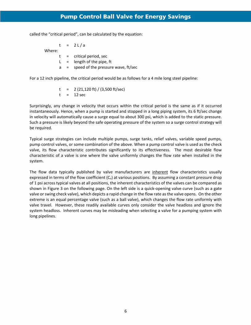
called the “critical period”, can be calculated by the equation: t = 2 L / a Where: t = critical period, sec L = length of the pipe, ft a = speed of the pressure wave, ft/sec For a 12 inch pipeline, the critical period would be as follows for a 4 mile long steel pipeline: t = 2 (21,120 ft) / (3,500 ft/sec) t = 12 sec Surprisingly, any change in velocity that occurs within the critical period is the same as if it occurred instantaneously. Hence, when a pump is started and stopped in a long piping system, its 6 ft/sec change in velocity will automatically cause a surge equal to about 300 psi, which is added to the static pressure. Such a pressure is likely beyond the safe operating pressure of the system so a surge control strategy will be required.
Typical surge strategies can include multiple pumps, surge tanks, relief valves, variable speed pumps, pump control valves, or some combination of the above. When a pump control valve is used as the check valve, its flow characteristic contributes significantly to its effectiveness. The most desirable flow characteristic of a valve is one where the valve uniformly changes the flow rate when installed in the system.
The flow data typically published by valve manufacturers are inherent flow characteristics usually expressed in terms of the flow coefficient (Cv) at various positions. By assuming a constant pressure drop of 1 psi across typical valves at all positions, the inherent characteristics of the valves can be compared as shown in Figure 3 on the following page. On the left side is a quick‐opening valve curve (such as a gate valve or swing check valve), which depicts a rapid change in the flow rate as the valve opens. On the other extreme is an equal percentage valve (such as a ball valve), which changes the flow rate uniformly with valve travel. However, these readily available curves only consider the valve headloss and ignore the system headloss. Inherent curves may be misleading when selecting a valve for a pumping system with long pipelines.

Pump Control Ball Valve for Energy Savings
7
FIGURE 3. Inherent Flow Characteristics
The inherent characteristic curves must be transformed for a given pipeline application to consider the relative headloss of the piping system. So when a valve such as a ball valve is installed in a pipeline, the location of the curve varies with the length of the pipeline as shown in Figure 4 on the following page. The curve shown on the right is the inherent flow characteristic curve because the system is zero feet long. The other curves are installed flow characteristic curves because they vary with the system length. As the length of the pipeline increases, the characteristic curves for the same valve shifts to the left. Hence, the same valve can be very close to equal‐percentage in one system and quick‐opening in another. The longer the pipeline, the more the valve tends to be quick‐opening. A quick‐opening valve will change the flow suddenly and is more apt to cause surges because it effectively controls the flow for only one half of its travel. Ideally, the most desirable installed flow curve for a pumping system is linear such as the curve in the middle. Therefore, since inherent curves shift to the left when the system is included, the valve with an equal percentage inherent curve is the most desirable. Referring again to Figure 3, the most desirable valve for a long systems would be an equal percentage ball valve.

Pump Control Ball Valve for Energy Savings
8
FIGURE 4. Installed Flow Characteristics
But the flow curves can also be affected by size in addition to type. For example, installing an 8 inch valve in a 12 inch system will shift the curve back to the right as shown in Figure 5. The shift is logical because an 8 inch valve will decrease the flow more rapidly than a 12 inch valve in the same system. So when selecting a valve, the size and its maximum flow velocity is as important as the type. Ball valves are commonly smaller than line size because of their low headloss and ability to operate at velocities up to 35 ft/sec.
FIGURE 5. Installed Flow Characteristics By Size
Conclusion Because AWWA C507 ball valves have the lowest headloss and best flow characteristic, they are the preferred valve for pump control for both water and wastewater service. Ball valves can be equipped with electric motor or hydraulic actuators for reliable pump control service.

Pump Control Ball Valve for Energy Savings
9
References
1. Bosserman, Bayard E. “Control of Hydraulic Transients”, Pumping Station Design, Butterworth‐Heinemann, 2nd ed., 1998, Sanks, Robert L. ed., pp. 153‐171.
2. Hutchinson, J.W., ISA Handbook of Control Valves, 2nd ed., Instrument Society of America, 1976,
pp. 165‐179. 3. Kroon, Joseph R., et. al., “Water Hammer: Causes and Effects”, AWWA Journal, November, 1984,
pp. 39‐45. 4. AWWA M49. 2017. “Quarter‐Turn Valves: Head Loss, Torque, and Cavitation Analysis”, 3rd edition,
Denver, Colo.
Disclaimer Val‐Matic White Papers are written to train and assist design engineers in the understanding of valves and fluid systems. Val‐Matic offers no warranty or representation as to design information and methodologies in these papers. Use of this material should be made under the direction of trained engineers exercising independent judgement.