Pulse Sequencer Software - Software Manual · Pulse Sequencer Software ... Apply analog or digital...
91
Software Manual Pulse Sequencer Software V 4.1 R&S ® SMU-K6 1408.7662.02 R&S ® SMJ-K6 1409.2558.02 R&S ® SMATE-K6 1404.8006.02 R&S ® AFQ-K6 1401.5606.00 R&S ® AMU-K6 1402.9805.02 R&S ® SMBV-K6 1415.8390.02 1171.5202.42-12 1 E-1
Transcript of Pulse Sequencer Software - Software Manual · Pulse Sequencer Software ... Apply analog or digital...

Software Manual
Pulse Sequencer SoftwareV 4.1
R&S® SMU-K6 1408.7662.02
R&S® SMJ-K6 1409.2558.02
R&S® SMATE-K6 1404.8006.02
R&S® AFQ-K6 1401.5606.00
R&S® AMU-K6 1402.9805.02
R&S® SMBV-K6 1415.8390.02
1171.5202.42-12 1 E-1

1171.5202.42-12 2 E-1
Dear Customer,R&S® is a registered trademark of Rohde & Schwarz GmbH & Co. KG. Throughout this manual, the R&S® SMU-K6, R&S® SMJ-K6, R&S® SMATE-K6, R&S® AFQ-K6, R&S® AMU-K6 and R&S® SMBV-K6 isabbreviated as R&S Pulse Sequencer.Trade names are trademarks of the owners.

Table of Content
1 Abbreviations................................................................................6
2 Introduction...................................................................................7
3 Release Notes................................................................................8
4 Installation...................................................................................11
Hardware Requirements................................................................................11Minimum Instrument Configuration................................................................12Software Requirements..................................................................................13Installation......................................................................................................14
5 Starting the Pulse Sequencer....................................................15
6 Migrating from V 1.x to V 2.x or V 3.x.......................................16
7 Configuring the Pulse Sequencer.............................................17
8 The Project Tree..........................................................................20
9 First Steps....................................................................................21
10 Setting up the Instrument Link..................................................22
11 Creating New Pulses...................................................................24
Timing Parameters.........................................................................................25Delay Time..........................................................................................25Rise Time............................................................................................25On Time..............................................................................................25Fall Time.............................................................................................25Off Time..............................................................................................26PRI / PRF............................................................................................26
Arbitrary Pulse Envelope................................................................................26I/Q Data..........................................................................................................27Importing Data................................................................................................27General Pulse Settings...................................................................................28Jitter Settings.................................................................................................30
Uniform Distribution.............................................................................31Normal Distribution..............................................................................31Linear Ramp........................................................................................32Sine.....................................................................................................32Staircase.............................................................................................33Value List (Uniform).............................................................................33Value List (Ordered)............................................................................33Shape (Interpolated)............................................................................33Rules List............................................................................................34
Using Tables as Source for Jitter Values.......................................................35Combining Multiple Jitter Profiles...................................................................36Modulation Settings........................................................................................36The Data Source Editor..................................................................................38
1171.5202.42-12 3 E-1

Built-In Modulation Types...............................................................................39Marker Settings..............................................................................................48
12 Creating Sequences....................................................................49
13 The Sequence Editor..................................................................50
General Sequence Settings...........................................................................52
14 The Baseband Filter Dialog........................................................54
15 Report Generation.......................................................................56
16 Overlaying Pulse Entries............................................................58
Overlay Application Examples........................................................................59Radar Antenna TX, RX Simulation......................................................59Sector Blanking...................................................................................59
17 The Sequence View.....................................................................60
Time Domain Display.....................................................................................61Marker (Cursor) Functions.............................................................................64I/Q Plane........................................................................................................64FFT Spectrum................................................................................................65
18 The Transfer Panel......................................................................66
19 Multi-Segment Waveforms.........................................................68
General MSW Settings...................................................................................68MSW Editor....................................................................................................69Building Multi-Segment Waveforms...............................................................71Operating Multi-Segment Waveforms............................................................73
20 RF Lists........................................................................................74
21 The Log Panel..............................................................................78
22 Plug-in Modules..........................................................................79
The Plug-in Mechanism..................................................................................79The Programming API....................................................................................79
Get Type.............................................................................................79Get Version.........................................................................................79Set Name............................................................................................80Get Comment / Explanation................................................................80Get Author...........................................................................................80Get Error.............................................................................................80Initialization.........................................................................................81Shutdown............................................................................................81Setup Parameters...............................................................................81Set Values...........................................................................................82Plug-in Modulation Engine..................................................................82Plug-in Modulation Engine 2...............................................................84Query Plug-in Configuration Parameters.............................................85Setting Plug-in Configuration Parameters...........................................86
1171.5202.42-12 4 E-1

23 Sample Rate Considerations.....................................................87
Minimum Pulse Width....................................................................................87Timing Error...................................................................................................88Dynamic Range..............................................................................................89
1171.5202.42-12 5 E-1

Abbreviations R&S K6 Pulse Sequencer
1 Abbreviations
AM Amplitude ModulationARB Arbitrary (Arbitrary Waveform Generator)ASK Amplitude Shift KeyingAWGN Additive White Gaussian NoiseCW Continuous WaveGPIB General Purpose Instrument (Instrumentation) BusFFT Fast Fourier TransformationFM Frequency ModulationFSK Frequency Shift KeyingLAN Local Area NetworkPRBS Pseudo Random Bit SequencePRF Pulse Repetition TimePRT Pulse Repetition TimePRI Pulse Repetition IntervalPSK Phase Shift KeyingQAM Quadrature Amplitude ModulationQPSK Quadrature Phase Shift KeyingRF Radio FrequencyUSB Universal Serial BusVISA Virtual Instrument Software ArchitectureVSB Vestigial Side BandXML Extensible Markup Language
1171.5202.42-12 6 E-1

R&S K6 Pulse Sequencer Introduction
2 Introduction
The R&S Pulse Sequencer software allows the flexible generation of complex pulses and pulse patterns. It is intended for use with the Rohde & Schwarz vector signal generators R&S SMU200A, R&S SMJ100A, R&S SMATE200A, R&S AMU200A, R&S AFQ100A,B and R&S SMBV100A.This software provides an easy to use interface to build custom pulse envelopes, apply modulation or jitter as well as markers. It is also possible to build sophisticated test patterns for radar receiver tests. Inaddition, proprietary modulation schemes or envelopes can be applied by using the Pulse Sequencers plug-in mechanism.
Features: Easily generate complex pulse shapes and pulse patterns Create and manage a library of pulses as source for building pulse sequences Apply analog or digital intra pulse modulation such as AM, ASK, FM, FSK, PSK, FM Chirps Extend built in modulation schemes with custom plug-ins Simulate technical systems by applying up to four jitter types to any pulse parameter and define
the distribution Create multi segment waveforms for fast hopping between pulse patterns Create RF lists for fast hopping of frequencies and levels Organize your work in projects, pulse libraries and sequence libraries Create reports during pulse pattern generation as text file or by the use of plugin as Microsoft
EXCEL spread sheet Compatible with R&S SMU200A, R&S SMJ100A, R&S SMATE200A, R&S AMU200A,
R&S AFQ100A,B and R&S SMBV100A Automatic transfer of the generated waveforms to the signal source using VISA Interface
(GPIB, LAN, USB) Additional instrument options can be used to apply noise (AWGN), impairments or fading
profiles to any pulse sequence. Two path instruments allow the combination and synchronization of two independent signals.
1171.5202.42-12 7 E-1

Release Notes R&S K6 Pulse Sequencer
3 Release Notes
Changes from Version 1.x to Version 2.1
Pulse Settings:- AWGN added to pulse settings- 4 independent jitters compared to three in V 1.0- New jitter types ramp, stair case, sine- Custom I/Q data can be imported
Modulation:- Custom FM-chirp can be defined by polynomial- FSK(2) added with two frequencies at definable durations- FSK deviation changed to -Fdev...+Fdev- FM-chirps hold the frequency during rise and fall period- Polyphase modulation (Frank, P1...P4) added- New data source editor with custom and built-in data
User Interface and Graphics:- New view mode frequency versus time- FFT view changed to peak detector mode- Removed unmodulated / modulated separation in pulse library- New RF Lists features- Up to 42 RF lists possible in project
Instrument control:- Instrument manager with LAN search- New instrument control concept with block chart- Improved file transfer
1171.5202.42-12 8 E-1

R&S K6 Pulse Sequencer Release Notes
Changes from Version 2.x to Version 3.0
• Maximum number of modulation plugin variables increased to 255• Modulation plugins can generate marker data• ARB preset can be suppressed during waveform transfer• Added MSK modulation• Square Root ramp type• Max. number of RF lists increased to 100• MSW Sequencer mode added to Multi Segment Waveforms• DFS signal generation updates• Bug fixes
Changes from Version 3.0 to Version 3.1
• Data sources take bits and hexadecimal input• Added plugins and project files for ADS-B, Mode-S, Polynomial Chirp• Rebuild using CVI 2009 Runtime Libraries• Fixed problem loading DFS EXCEL report plugin• Application shows icon in task bar
Changes from Version 3.1 to Version 3.4
• Fonts changed in entire applications to “Arial” fixes problems on some installations• Improved calculation of AWGN• Improved Multi-Segment waveform editor• Attempting to erase a used data source displays warning message• Empty data sources could have caused a crash• Data sources can now be sorted• Sequences that are used in Multi-Segment waveforms cannot be deleted• Improved waveform preview• Closing the baseband filter dialog did close the entire application• Added Japan and Korea DFS signals• Added new RFID plugins and projects• Removed some DLL dependencies
1171.5202.42-12 9 E-1

Release Notes R&S K6 Pulse Sequencer
Changes from Version 3.4 to Version 3.5
• Fixed application crash for waveforms that are shorter than 1024 samples• Fixed erroneous PRF calculation in DFS ETSI 301 893 V1.5.1, Type 5 and 6• Added DFS ETSI 301 893 V1.6.0 Draft ( = ETSI 301 893 V1.6.1 )• DME pulse timing fixed in example project• All user files are now placed in the user's home directory instead of the application folder. This
avoids the need for elevated user rights.
Changes from Version 3.5 to Version 3.7
• Removed NFC/RFID plugins and project files. These will now be provided with a separate application note.
• DFS Updates• Fixed renaming of output file name when waveform was created
Changes from Version 3.7 to Version 3.8
• Local waveform file names were not properly resolved
Changes from Version 3.8 to Version 3.9
• Support for new instruments added
Changes from Version 3.9 to Version 4.0
• Upgrade to newer CVI runtime 2010• SMBV100A limits changed to 200 MHz clock, 160 MHz bandwidth, 256 Msamples• All project files modified to use a relative path as target on the instrument• Fixed bug: The temporary path setting was not saved properly• The value range for polynomial chirps was increased• DFS user manual updated
Changes from Version 4.0 to Version 4.1
• Fixed bug in polyphase modulation
1171.5202.42-12 10 E-1
R&S K6 Pulse Sequencer Installation
4 Installation
The R&S Pulse Sequencer is intended for installation on a desktop PC running a Microsoft Windows® XP Professional, Microsoft® Vista, or Microsoft® Windows 7 operating system. The following list of prerequisites should be met before installing the application.
1.1 Hardware Requirements
Minimum Requirements AMD or Intel CPU running at 1 GHz or faster 1 GB RAM Screen resolution of 1024x768 pixel or higher 20 MB free HD space1
Fast IDE or S-ATA drive2
100 M Bit LAN or VISA compatible GPIB adapter for interfacing with instrument
Recommended Hardware AMD or Intel CPU running at 2 GHz 2 GB RAM Screen resolution of 1024x768 pixel 10 GB free HD space1
Fast IDE or S-ATA drive2
1 G Bit LAN or VISA compatible GPIB adapter for interfacing with instrument
1The space is required for program installation. During waveform creation R&S Pulse Sequencer requires large temporary files. As a rule of thumb 9 Bytes per sample need to be considered for temporary file space. Example: 125 M Samples of waveform data call for about 1 G Byte of temporary HD space. 2 The HD is not only required to install the Pulse Sequencer software but also holds temporary data. Access should be as fast as possible to speed up waveform calculation.
1171.5202.42-12 11 E-1
Installation R&S K6 Pulse Sequencer
1.2 Minimum Instrument Configuration
The following overview lists minimum instrument requirements for the different R&S Vector Signal Generators or Modulation Generators. Please note that the configuration required for your application may need additional instrument options. This overview only points out which minimum requirements must be met.
SMU200AR&S SMU200A 1141.2005.02 Vector Signal GeneratorR&S SMU-B103 1141.8603.02 100 kHz to 3 GHzR&S SMU-B11 1159.8411.02 Baseband Generator with ARB
16 Msample and Digital ModulationR&S SMU-B13 1141.8003.04 Baseband Main ModuleR&S SMU-K6 1408.7662.02 Pulse Sequencer
SMJ100AR&S SMJ100A 1403.4507.02 Vector Signal GeneratorR&S SMJ-B103 1403.8502.02 100 kHz to 3 GHzR&S SMJ-B51 1410.5605.02 Baseband Generator with ARB
16 MsampleR&S SMJ-B13 1403.9109.02 Baseband Main ModuleR&S SMJ-K6 1409.2558.02 Pulse Sequencer
AFQ100AR&S AFQ100A 1401.3003.02 I/Q Modulation GeneratorR&S AFQ-B10 1401.5106.02 Waveform Memory 256 MsampleR&S AFQ-K6 1401.5606.02 Pulse Sequencer
AFQ100BR&S AFQ100B 1410.9000.02 UWB Signal and I/Q Modulation GeneratorR&S AFQ-B12 1411.0007.02 Waveform Memory 512 MsampleR&S AFQ-K6 1401.5606.02 Pulse Sequencer
SMBV100AR&S SMBV100A 1407.6004.02 Vector Signal GeneratorR&S SMBV-B103 1407.9603.02 9 kHz to 3.2 GHzR&S SMBV-B51 1407.9003.02 Baseband Generator with ARB
32 Msample, 60 MHz RF bandwidthR&S SMBV-B92 1407.9403.02 Hard Disk (removable)R&S SMBV-K6 1415.8390.02 Pulse Sequencer
SMATE200AR&S SMATE200A 1400.7005.02 Vector Signal GeneratorR&S SMATE-B103 1401.1000.02 100 kHz to 3 GHzR&S SMATE-B11 1401.2807.02 Baseband Generator with ARB
16 Msample and Digital ModulationR&S SMATE-B13 1401.2907.02 Baseband Main ModuleR&S SMATE-K6 1404.8006.02 Pulse Sequencer
1171.5202.42-12 12 E-1

R&S K6 Pulse Sequencer Installation
1.3 Software Requirements
Microsoft Windows® XP Professional or Windows® Vista Rohde & Schwarz VISA IO Libraries for Instrument Control, Rev. M.01.01 or
other VISA runtime library, such as National Instruments VISA 4.0 Minimum instrument firmware release
SMU200A, SMATE200A, SMJ100A 02.05.222.2402.10.111.116 (Sequencer)
SMBV100A 02.05.200.1902.15.85.47 (Sequencer)
AFQ100A, AFQ100B 02.10.250 beta
Any Microsoft® Office package containing Microsoft® EXCEL for the use of the DFS reporting feature. Please see the installation chapter for details.
1171.5202.42-12 13 E-1

Installation R&S K6 Pulse Sequencer
1.4 Installation
If you already have version 1.x of the R&S Pulse Sequencer software installed on your machine it is advisable to install version 2.x into a separate directory in order to keep your old project files and settings. A separate section in this document describes the migration path from V 1.x projects to V 2.x projects.Before you install the Pulse Sequencer software a VISA runtime library must be installed on your system. Please refer to the documentation provided with your VISA software for installation details.The installation of the R&S Pulse Sequencer is started by executing the self extracting installer. After completion your application directory contains the following structure.
K6 Pulse Sequencer.exe Application executable \Plugins Plug-ins for intra pulse modulation or reporting \manual User manual files (pdf format) \cvirte Run time environment files
User files are placed into the user's home path under %HOMEDRIVE%%HOMEPATH%\Rohde-Schwarz\K6
settings.ini Program settings file \Projects Project files \Waveforms Storage location for K6 generated waveform files \LogFiles Text report files generated by the application \Reports Microsoft EXCEL reports for DFS signal generation \Temp Temporary files \Source Code Code examples for custom plug-ins
The R&S Pulse Sequencer software is started by executing the ‘K6 Pulse Sequencer.exe’ file. If not otherwise selected the installer places an icon on your desktop that links to this executable.When the Pulse Sequencer software starts up it scans the sub directory Plugins for available user extensions. All valid plug-ins are automatically loaded and listed in the main project tree.
Note: Pulse Sequencer V 2.x provides a plug-in that automatically fills in Microsoft® EXCEL reports during the generation of DFS pulse trains. A separate manual bundled with this application explains the DFS signal generation process and use in more detail.If you do not have Microsoft EXCEL installed on your PC or do not require to generate DFS signals it is suggested to remove the associated plug-in in the Plugins sub directory. The plug-in name is ‘Report-DFS.dll’ and if placed outside of the Plugins sub directory it will not be loaded during start-up.
1171.5202.42-12 14 E-1

R&S K6 Pulse Sequencer Starting the Pulse Sequencer
5 Starting the Pulse Sequencer
When the Pulse Sequencer software is started the first time it automatically loads an examples project. This project demonstrates various capabilities of the Pulse Sequencer software and may be used as a starting point for own waveforms.General program settings, such as the last project or active instruments are stored in the settings.ini file in the application directory. In case the Pulse Sequencer software does not start up as expected it is suggested to remove this file which would cause the software to start with default settings.
In addition, several command line options exist for debugging purpose. These options can be used in case the application does not start up correctly.
--dstartup create additional debug out during start-up (stdout window)--no-load-project do not automatically load a project during start-up--no-check-instr do not verify an instrument link during start-up--no-screen-test do not test for a minimum screen resolution during start-up
1171.5202.42-12 15 E-1

Migrating from V 1.x to V 2.x or V 3.x R&S K6 Pulse Sequencer
6 Migrating from V 1.x to V 2.x or V 3.x
Pulse Sequencer project data is saved as .prj files in the XML file format. Due to the nature of this file format most settings from version 1.x can be imported by version 2.x. However, additional settings that were implemented in V 2.x are not present in older project files. The following steps are recommended when loading Pulse Sequencer V 1.x project files.
1. Keep your existing V 1.x installation and install V 2.x into a separate directory2. Load the project file from V 1.x into V 2.x3. Verify and correct all pulse modulation related settings. For modulated pulses click at least
once into one field of the pulse modulation settings to let the software update its settingstable.
4. If data patterns were used for intra-pulse modulation this data needs to be provided again in thedata source editor (on a project base).
5. Configure jitter 4 settings of all pulses.6. Update the jitter settings in all sequences. The names have changed between V 1.x and V 2.x.7. Save the file under a different name using the ‘Save Project As’ menu option.
NoteIf you do not need to keep any existing Pulse Sequencer V 1.x installation it is recommended to entirely remove the old installation before attempting to install V 2.x. You may use the de-installer provided with V 1.x but it is suggested to manually clean all remaining files in the program directory. This is required because the de-installer leaves plug-ins and project files untouched as they might have been changed by the user.
1171.5202.42-12 16 E-1

R&S K6 Pulse Sequencer Configuring the Pulse Sequencer
7 Configuring the Pulse Sequencer
After a fresh installation the R&S Pulse Sequencer starts with a default configuration which is defined inthe settings.ini file in the application directory.
All plug-ins from the sub directory Plugins are loaded The project ‘examples.prj’ is loaded All temporary files are located under C:\ Program messages are written to the log panel Some example VISA connections are listed on the instrument panel
The first step after a fresh installation is to verify the general settings under 'Options → Preferences' from the menu bar.
Log Program Messages to Log WindowWrites all program messages to the log panel. Writing these messages to the log slows down some operations but provides useful information about what tasks are performed or possible causes of errors.Save Current Project on ExitAlways saves the current project when the R&S Pulse Sequencer software terminates.
1171.5202.42-12 17 E-1
Fig. 1: General settings dialog
Configuring the Pulse Sequencer R&S K6 Pulse Sequencer
Location for Temporary FilesThe folder for temporary files specifies the location where the R&S Pulse Sequencer keeps temporary data during waveform creation. Read and write access to this drive should be fast. Therefore, it is suggested to use a local hard drive instead of network storage space. This setting is effective after the next program start since the software creates temporary files during start-up. The required file size depends on the created waveforms. As a rule of thumb 9 bytes are required per sample during waveform calculation. For example, if a sequence generates 10 M samples of waveform output the temporary file rises to about 90 M Bytes. Using a baseband filter increases the memory consumption by a factor of two.
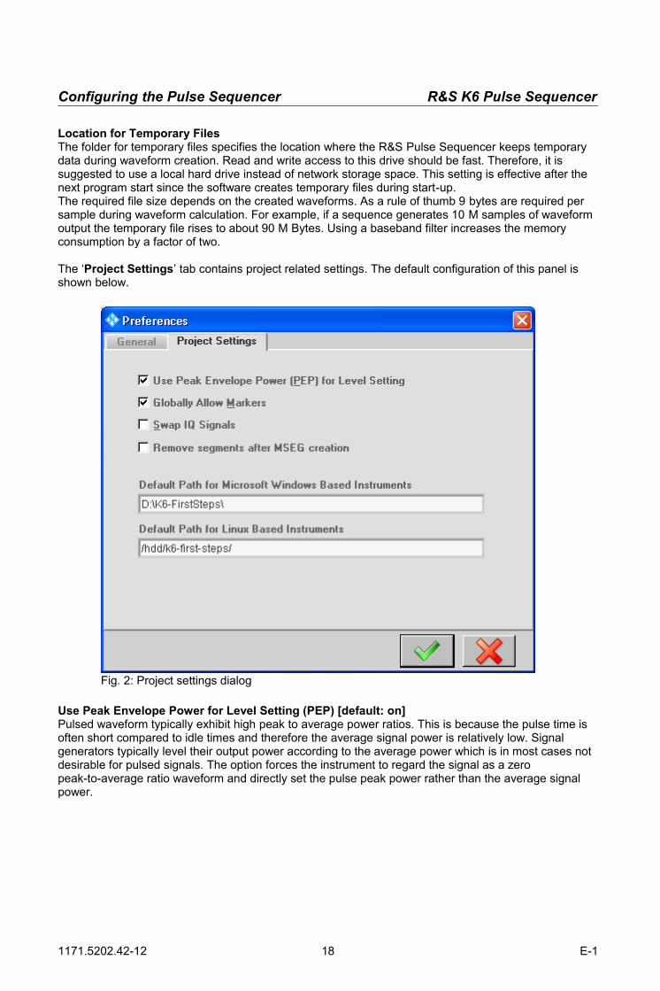
The ‘Project Settings’ tab contains project related settings. The default configuration of this panel is shown below.
Use Peak Envelope Power for Level Setting (PEP) [default: on]Pulsed waveform typically exhibit high peak to average power ratios. This is because the pulse time is often short compared to idle times and therefore the average signal power is relatively low. Signal generators typically level their output power according to the average power which is in most cases not desirable for pulsed signals. The option forces the instrument to regard the signal as a zero peak-to-average ratio waveform and directly set the pulse peak power rather than the average signal power.
1171.5202.42-12 18 E-1
Fig. 2: Project settings dialog
R&S K6 Pulse Sequencer Configuring the Pulse Sequencer
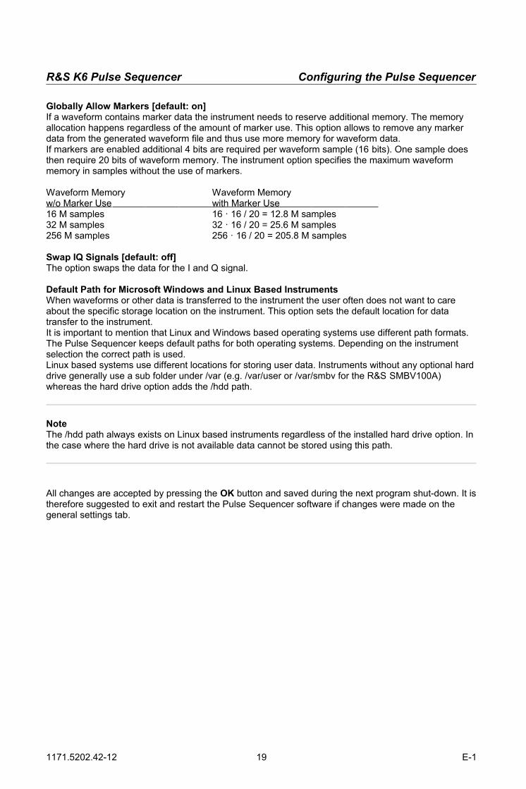
Globally Allow Markers [default: on]If a waveform contains marker data the instrument needs to reserve additional memory. The memory allocation happens regardless of the amount of marker use. This option allows to remove any marker data from the generated waveform file and thus use more memory for waveform data.If markers are enabled additional 4 bits are required per waveform sample (16 bits). One sample does then require 20 bits of waveform memory. The instrument option specifies the maximum waveform memory in samples without the use of markers.
Waveform Memory Waveform Memoryw/o Marker Use with Marker Use 16 M samples 16 · 16 / 20 = 12.8 M samples32 M samples 32 · 16 / 20 = 25.6 M samples256 M samples 256 · 16 / 20 = 205.8 M samples
Swap IQ Signals [default: off]The option swaps the data for the I and Q signal.
Default Path for Microsoft Windows and Linux Based InstrumentsWhen waveforms or other data is transferred to the instrument the user often does not want to care about the specific storage location on the instrument. This option sets the default location for data transfer to the instrument.It is important to mention that Linux and Windows based operating systems use different path formats. The Pulse Sequencer keeps default paths for both operating systems. Depending on the instrument selection the correct path is used.Linux based systems use different locations for storing user data. Instruments without any optional harddrive generally use a sub folder under /var (e.g. /var/user or /var/smbv for the R&S SMBV100A) whereas the hard drive option adds the /hdd path.
NoteThe /hdd path always exists on Linux based instruments regardless of the installed hard drive option. In the case where the hard drive is not available data cannot be stored using this path.
All changes are accepted by pressing the OK button and saved during the next program shut-down. It istherefore suggested to exit and restart the Pulse Sequencer software if changes were made on the general settings tab.
1171.5202.42-12 19 E-1

The Project Tree R&S K6 Pulse Sequencer
8 The Project Tree
All data, such as pulses, pulse sequences, Multi-Segmentwaveforms and RF Lists are organized in projects. The visualrepresentation of the project contents is the project tree which showsall items organized in different libraries. Empty Pulse Sequencer projects contain no data at all. Thus,starting a new project always requires to define pulses first, and thensequences which can be turned into waveforms.The following section describes the project tree content in moredetail.
The Pulse Library contains all pulses defined within the project.Pulses are the fundamental building blocks of any signal andtherefore need to be created first. Each pulse entry can be furtherexpanded to unveil detailed settings, such as timing, modulation,jitter and marker data. Pulses that use custom plug-ins are indicatedwith a small red dot next to the pulse icon. Selecting a pulse entry orone of its sub items shows the associated editor window on the rightside.Please note that pulses cannot be turned into a waveform. Insteadthe pulse entry only contains a mathematical description of pulseparameters. The sequence combines pulses and is the basis forwaveform generation.
The Sequence Library contains all pulse sequences defined withinthe project. A sequence defines how pulses are arranged to form awaveform. It also adds parameters such as the sample rate orbaseband filter settings. The sequence can be compiled into awaveform and transferred to the Vector Signal Generator.
The Multi Segment Waveform Library contains all Multi-Segmentwaveform definitions defined within the project. A Multi-Segmentwaveform is a concatenation of sequences that can be turned intowaveforms using a batch processing functionality. This simplifies thegeneration of many waveforms and it also permits arbitrary jumpsbetween such waveforms.
The RF List Library contains all RF Lists defined within the project. An RF List contains frequency and level pairs which may be combined with any baseband signal. The RF List affects only the RF section ofthe instrument and allows for hops across a wide frequency or level range.
The Plug-in tree branch contains all plug-in modules that were loaded during program start. Plug-ins are Dynamic Link Libraries (DLLs) that contain the maths used for intra pulse modulation. The Pulse Sequencer software comes with example Plug-ins that can be used as a starting point for customimplementations.
Items can be hidden from the project tree. This is useful if sequences or Multi-Segment waveforms contain pulses that do not need to be altered by this user. Use 'Project → Hide Tree Entries' from the menu bar to toggle the view of hidden entries.
1171.5202.42-12 20 E-1

R&S K6 Pulse Sequencer First Steps
9 First Steps
The following steps demonstrate a typical work flow for the generation of a waveform.
Create a new project (File → New Project) Create a new pulse entry (Create → New Pulse) and assign it a name
o Select the timing tab:Specify the pulse timing, e.g. rise time, on time, fall time and the edge shapes
o Optionally select the settings tab:Set levels, frequency offset, AWGN
o Optionally select the modulation tab:Set intra-pulse modulation and define the data sources
o Optionally select the marker tab:Modify the default marker settings
Create a new sequence (Create → New Sequence) and assign it a nameo Set-up the first pulse entry or add additional pulse entries by clicking the
‘Add new Sequence Entry’ button just above the sequence tableo Set the number of repetitions and click into the marker fields M1 through M4 to set the
marker masking for multiple repetitionso Change the desired ARB sample if the default value is not sufficiento Specify the local waveform file name, e.g. waveforms\MyPulse.wv
Press the ‘Build Waveform’ button to create the waveform from the sequence Optionally select the ‘Sequence View’ tab to inspect the result Select the ‘Transfer’ panel
o Activate the instrument manager panel and set-up your instrument link(this step is only required once)
o Configure the remote file name and the RF sectiono Hit the 'Transfer' button to send your waveform data to the instrument
1171.5202.42-12 21 E-1
Setting up the Instrument Link R&S K6 Pulse Sequencer
10 Setting up the Instrument Link
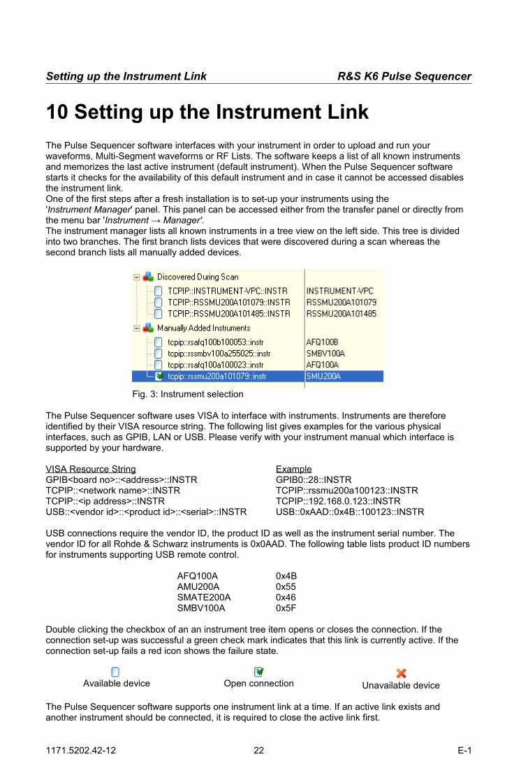
The Pulse Sequencer software interfaces with your instrument in order to upload and run your waveforms, Multi-Segment waveforms or RF Lists. The software keeps a list of all known instruments and memorizes the last active instrument (default instrument). When the Pulse Sequencer software starts it checks for the availability of this default instrument and in case it cannot be accessed disables the instrument link.One of the first steps after a fresh installation is to set-up your instruments using the 'Instrument Manager' panel. This panel can be accessed either from the transfer panel or directly from the menu bar 'Instrument → Manager'.The instrument manager lists all known instruments in a tree view on the left side. This tree is divided into two branches. The first branch lists devices that were discovered during a scan whereas the second branch lists all manually added devices.
The Pulse Sequencer software uses VISA to interface with instruments. Instruments are therefore identified by their VISA resource string. The following list gives examples for the various physical interfaces, such as GPIB, LAN or USB. Please verify with your instrument manual which interface is supported by your hardware.
VISA Resource String ExampleGPIB<board no>::<address>::INSTR GPIB0::28::INSTRTCPIP::<network name>::INSTR TCPIP::rssmu200a100123::INSTRTCPIP::<ip address>::INSTR TCPIP::192.168.0.123::INSTRUSB::<vendor id>::<product id>::<serial>::INSTR USB::0xAAD::0x4B::100123::INSTR
USB connections require the vendor ID, the product ID as well as the instrument serial number. The vendor ID for all Rohde & Schwarz instruments is 0x0AAD. The following table lists product ID numbersfor instruments supporting USB remote control.
AFQ100A 0x4BAMU200A 0x55SMATE200A 0x46SMBV100A 0x5F
Double clicking the checkbox of an an instrument tree item opens or closes the connection. If the connection set-up was successful a green check mark indicates that this link is currently active. If the connection set-up fails a red icon shows the failure state.
Available device Open connection Unavailable device
The Pulse Sequencer software supports one instrument link at a time. If an active link exists and another instrument should be connected, it is required to close the active link first.
1171.5202.42-12 22 E-1
Fig. 3: Instrument selection

R&S K6 Pulse Sequencer Setting up the Instrument Link
The delete button removes a selected entry from the instrument list. Make sure to close the instrument link before attempting to delete the device from the list.
New instruments can be added at any time by using the controls shown below. The first input field depends on the selected hardware interface. The second line is used for an optional comment. The comment has no function but it is displayed in the second column of the instrument tree.
Clicking the 'Add Manually' button adds the new instrument to the instrument tree.
The Pulse Sequencer also provides two scanning functions that can be used to discover instruments. An instrument scan can be performed on GPIB hardware or in a local area network (LAN). Use the button 'Scan GPIB' to add all supported devices that are connected to a local GPIB controller.
The board number is zero for the first board installed in the PC.
The 'Scan LAN' button performs a search for instruments in a LAN. In order to narrow down the search in larger LANs a domain name should be provided for the search. By default Rohde & Schwarz instruments are configured to use the 'Instrument' domain.
1171.5202.42-12 23 E-1
Fig. 4: Adding instruments manually
Fig. 5: Scanning for instruments
Creating New Pulses R&S K6 Pulse Sequencer
11 Creating New Pulses
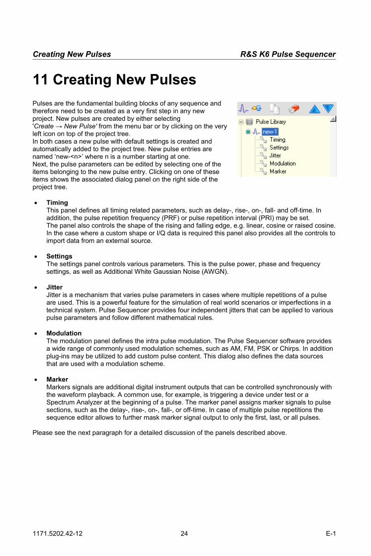
Pulses are the fundamental building blocks of any sequence andtherefore need to be created as a very first step in any newproject. New pulses are created by either selecting'Create → New Pulse' from the menu bar or by clicking on the veryleft icon on top of the project tree.In both cases a new pulse with default settings is created andautomatically added to the project tree. New pulse entries arenamed ‘new-<n>’ where n is a number starting at one.Next, the pulse parameters can be edited by selecting one of theitems belonging to the new pulse entry. Clicking on one of theseitems shows the associated dialog panel on the right side of theproject tree.
TimingThis panel defines all timing related parameters, such as delay-, rise-, on-, fall- and off-time. In addition, the pulse repetition frequency (PRF) or pulse repetition interval (PRI) may be set.The panel also controls the shape of the rising and falling edge, e.g. linear, cosine or raised cosine.In the case where a custom shape or I/Q data is required this panel also provides all the controls toimport data from an external source.
SettingsThe settings panel controls various parameters. This is the pulse power, phase and frequency settings, as well as Additional White Gaussian Noise (AWGN).
JitterJitter is a mechanism that varies pulse parameters in cases where multiple repetitions of a pulse are used. This is a powerful feature for the simulation of real world scenarios or imperfections in a technical system. Pulse Sequencer provides four independent jitters that can be applied to various pulse parameters and follow different mathematical rules.
ModulationThe modulation panel defines the intra pulse modulation. The Pulse Sequencer software provides a wide range of commonly used modulation schemes, such as AM, FM, PSK or Chirps. In addition plug-ins may be utilized to add custom pulse content. This dialog also defines the data sources that are used with a modulation scheme.
MarkerMarkers signals are additional digital instrument outputs that can be controlled synchronously with the waveform playback. A common use, for example, is triggering a device under test or a Spectrum Analyzer at the beginning of a pulse. The marker panel assigns marker signals to pulse sections, such as the delay-, rise-, on-, fall-, or off-time. In case of multiple pulse repetitions the sequence editor allows to further mask marker signal output to only the first, last, or all pulses.
Please see the next paragraph for a detailed discussion of the panels described above.
1171.5202.42-12 24 E-1

R&S K6 Pulse Sequencer Creating New Pulses
1.5 Timing Parameters
Timing parameters affect the pulse shape andare usually the first and most importantparameters to define. The timing panelcontrols all phases of the pulse. This is thedelay-, rise-, on-, fall-, and off-time. Timevalues can be set in nanoseconds (ns),microseconds (µs), milliseconds (ms) orseconds (s). The total duration is automaticallycalculated and shown as sum below allsettings. This value cannot be edited. Analternative to setting the off time is to define apulse repetition interval or frequency. In thiscase the required off time is automaticallycomputed.
1.5.1 Delay Time
This is the time before the rising edge of the pulse. During this time the RF power is attenuated or totally suppressed. There is no modulation or data content present during this phase of the pulse. This setting may be used to shift the pulse location in time within the PRI (pulse repetition interval) time.
1.5.2 Rise Time
This parameter sets the total time of the rising pulse edge (zero to 100 percent). The RF level changes within this interval from the off-level to the on-level. Typically the off-level uses a high attenuation, such as 100 dB whereas the on-level only uses little or no attenuation. This produces a rising RF power slope.Modulation is already present during this phase of the pulse. Guard bits must be added to avoid truncation of data during the rising edge period.The shape of the rising edge can be selected between linear, cosine and raised cosine. Other shapes are possible using plug-ins or arbitrary envelope data.
1.5.3 On Time
The on time defines the period of time where the pulse power is held at a constant level defined by the on-level attenuation. Typically the on-level attenuation is zero and therefore the RF power set to the maximum. The on time is the total time from the very end of the rising edge to the very beginning of the falling edge (100 % level).
1.5.4 Fall Time
For the fall time the same applies as for the rising edge section. In contrast to the rising edge power changes from the on-level to the off-level.
1171.5202.42-12 25 E-1
Fig. 6: Pulse timing parameters

Creating New Pulses R&S K6 Pulse Sequencer
1.5.5 Off Time
The off time follows the falling edge of the pulse. During this time the RF power is suppressed to the off-level and no modulation is applied.The sum of all the above times form the PRT (pulse repetition time) or PRI (pulse repetition interval).
1.5.6 PRI / PRF
PRI and PRF values define the overall time of a pulse cycle. This value can be used alternatively to the pulse off time. In this case the software uses PRF or PRI to define the overall pulse cycle time and determines the off time automatically by adding the times for delay, rising edge, on period and falling edge. The remainder to the PRI is used as the off time.PRF or PRI settings are very useful if the pulse timing changes (e.g. by jitter) but the total duration of the pulse cycle must remain constant.
1.6 Arbitrary Pulse Envelope
Instead of defining a pulse by its rise-,on- and fall-time it is also possible touse arbitrary envelope data.Arbitrary envelope data affects the levelvalues versus time and therefore canbe used with any kind of intra pulsemodulation. The basic functionalitybehind arbitrary envelope data is thatthis data is multiplied with the existingpulse shape created from the timingparameters. Time wise the arbitraryenvelope is mapped to the pulse phaseconsisting of rise-, on-, and fall-time. Inan ideal case the rise- and fall-time isset to zero and the on-time defines thelength of the arbitrary pulse shape.Since arbitrary amplitude data ismultiplied with the existing pulse shapeit is suggested to use a values rangingfrom 0 to 1.0 to obtain correct levels.The Pulse Sequencer software useslinear interpolation between data pointsto compute the resulting pulseenvelope based on the given timingand ARB sample rate.
1171.5202.42-12 26 E-1
Fig. 7: Custom envelope data dialog

R&S K6 Pulse Sequencer Creating New Pulses
1.7 I/Q Data
The R&S Pulse Sequencer software can also make use of custom I/Q data for the intra-pulse modulation or envelope. Arbitrary I/Q data is applied during the rise-, on-, and fall-time of a pulse. If no rise-time and fall-time is set the I/Q data completely controls the pulse shape and the intra-pulse modulation.
1.8 Importing Data
The import tab loads arbitrary envelope or I/Q data into the Pulse Sequencer project. Once data is loaded it becomes part of the pulse definition and is saved in the project file. Copying the pulse creates a new pulse with a full copy of the imported data.
The 'Import Mode' control selects the mode between 'Level' (envelope data only) and 'I and Q' for full I/Q data import. Set the mode before attempting to load any data into the Pulse Sequencer project.
The two column controls define the columns in an ASCII file from which the envelope or I/Q data is imported. The Pulse Sequencer software accepts floating point ASCII text files with data organized in columns.
The 'Import Data From File' button selects the source file and imports data as defined into the project.
The 'Clear All Data' button removes all data from the project file.
Note about arbitrary data:Once arbitrary data is imported it becomes a permanent part of the project file. Importing a large number of data points may therefore grow the project file to a very large size. Arbitrary data remains present even if the ‘Use Custom Envelope or I/Q Data’ button is disabled. This allows the user to flexibly switch between both modes without the need to clear and reload any data. If arbitrary envelope data is not required any more it is suggested to clear it from the project file by using the ‘Clear All Data’ button. Copying a pulse also copies all arbitrary data.
1171.5202.42-12 27 E-1

Creating New Pulses R&S K6 Pulse Sequencer
1.9 General Pulse Settings
Level settings control the RF output power level during allphases of the pulse. The Pulse Sequencer uses two mainsettings to do so. One is the attenuation during the on-timewhereas the other is the attenuation during the off-time.Usually the attenuation during the off-time is much largerthan during the on-time which causes an RF pulse with arising and falling edge. If the attenuation was set to a highvalue for On and a low value for Off the result would be aninverse pulse. This setting could, for example, be usefulfor RFID devices that may require constant RF power.Attenuation values must always be positive numbersbetween zero and up to about 100 dB. The value of100 dB is usually sufficient when using a 16 bit ARB because the signal is fully suppressed beyond 96 dB of attenuation.
Log Droop specifies a logarithmic change (linear in dB scale) of the RF power during the on-time of a pulse. A positive number decreases the RF power by the set amount whereas a negative number increases power.
The Start Phase parameter sets the phase shift ofthe resulting RF wave. The permissible numberrange is -360.0 degrees to +360.0 degrees. Thephase setting refers to the starting point of the pulseand modulation may change this phase during thepulse.
Activating the Relative Phase check box keeps thesignal phase from the end of the previous pulse andadds the start phase to this value. This enables theuser to continue with a phase modulated signal fromone pulse to the next.
The Frequency Offset shifts the pulse in frequency away from the RF carrier. It is important that large enough ARB sample rates are set in the final sequence to allow for the desired frequency shift. A minimum of double the ARB sample rate is required for a given frequency offset.
The check box Hide Entry In Tree is used to hide this pulse entry in the project tree. This is useful if a large number of pulses exist and the user only needs to generate sequences or Multi-Segment waveforms without seeing or altering the underlying pulse definitions.
1171.5202.42-12 28 E-1
Fig. 8: Level settings
Fig. 9: Phase and frequency settings

R&S K6 Pulse Sequencer Creating New Pulses
The AWGN check box activates the generation of AdditiveWhite Gaussian Noise. The noise is superimposed duringall phases of the pulse at a set level and bandwidth.
The Level Att control sets the attenuation of the AWGNsignal from full scale.
The Bandwidth values sets the bandwidth in which theAWGN signal is created. In order to use this bandwidth it isrequired to chose a sufficiently high ARB sample rate in thefinal sequence.
The example below shows the resulting pulse amplitude in logarithmic scale with AWGN at 40 dB attenuation. The pulse amplitude is attenuated by 20 dB from full scale. It can be seen that the AWGN is superimposed during all phases of the pulse.
1171.5202.42-12 29 E-1
Fig. 11: Signal affected by AWGN
Fig. 10: AWGN settings

Creating New Pulses R&S K6 Pulse Sequencer
Jitter Settings
Applying jitter is one of the Pulse Sequencers most powerfulfunctions. This paragraph discusses jitter settings in detail andhighlights possible areas of use.In general, a jitter is understood as the change of a pulse parameterin either a random or ordered way. This parameter alterationenables the simulation of real world scenarios or technicalimperfections. Possible areas of use are the random variation of arising or falling edge position for the simulation of a technicallyimperfect trigger signal. Parameters such as the pulse repetitionfrequency may also be altered by using a staircase type jitter which is required for the generation of some radar signals.
The following parameters can be affected by jitter.
Delay Time [µs] Rise Time [µs] On Time [µs] Fall Time [µs] Off Time [µs] PRF, PRI [Hz, µs] Level Attenuation (On) [dB] Level Attenuation (Off) [dB] Frequency Offset [MHz] Phase [degrees] FM Deviation [MHz] Skip Entry [1,0]
The last item (Skip Entry) is not a pulse parameter. It is used to skip repetitions if a pulse is used multiple times within a sequence. A value of 1 skips the repetition whereas a value of 0 computes the pulse. The final number of pulses that result from a set of repetitions may vary if random data is used for the skip entry jitter.
The Pulse Sequencer software can assign up to four different jitters individually and simultaneously. Each jitter affects one particular pulse parameter from the list above and can use one of the following profiles.
Uniform Distribution Normal Distribution (Gauss) Linear Ramp Sine Wave Staircase Value List (uniform distributed or ordered) Interpolated Shape Rules List
These profiles are discussed in the following chapters in detail.
1171.5202.42-12 30 E-1
Fig. 12: Jitter settings
R&S K6 Pulse Sequencer Creating New Pulses
1.9.1 Uniform Distribution
The uniform distribution is characterized by the values Min, Max and Step. Values occur with the same probability in the range between the minimum and maximum level. The granularity is the Step value.
1.9.2 Normal Distribution
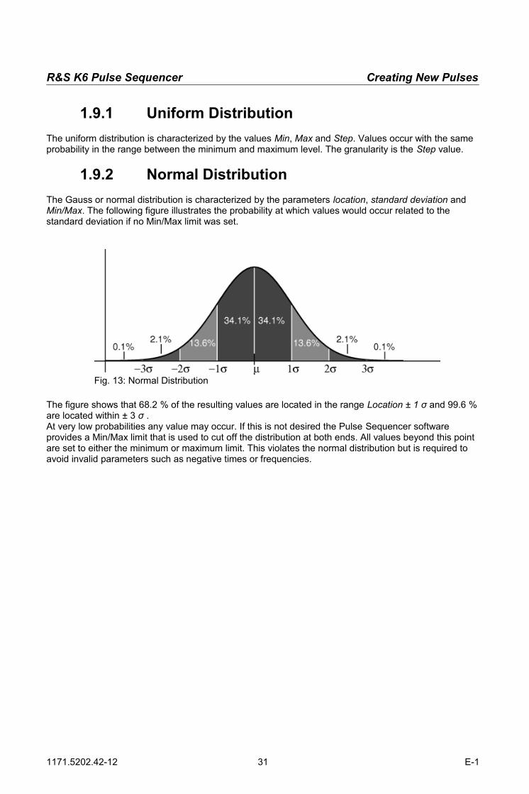
The Gauss or normal distribution is characterized by the parameters location, standard deviation and Min/Max. The following figure illustrates the probability at which values would occur related to the standard deviation if no Min/Max limit was set.
The figure shows that 68.2 % of the resulting values are located in the range Location ± 1 σ and 99.6 %are located within ± 3 σ .At very low probabilities any value may occur. If this is not desired the Pulse Sequencer software provides a Min/Max limit that is used to cut off the distribution at both ends. All values beyond this point are set to either the minimum or maximum limit. This violates the normal distribution but is required to avoid invalid parameters such as negative times or frequencies.
1171.5202.42-12 31 E-1
Fig. 13: Normal Distribution

Creating New Pulses R&S K6 Pulse Sequencer
1.9.3 Linear Ramp
The linear ramp changes a parameter from a minimum value to a maximum value.The following screen shot shows a series of 10 Gauss shaped pulses with the frequency changing from -20 MHz to +20 MHz following a linear ramp. The upper curve represents power versus time in logarithmic scale whereas the lower curve shows the frequency versus time.
1.9.4 Sine
The sine profile creates values that follow one period of a sine wave. The amplitude parameter sets the peak amplitude of the sine wave whereas the offset parameter sets a constant offset to the entire sine wave.The screen shot below shows a series of 100 pulses where the phase is varied from -180 degrees to +180 degrees following a sine wave shape.
1171.5202.42-12 32 E-1
Fig. 14: Example for pulse frequency affected by linear ramp jitter
Fig. 15: Example for pulse phase affected by sine wave jitter

R&S K6 Pulse Sequencer Creating New Pulses
1.9.5 Staircase
The staircase profile creates a sequence of identical values before it moves on the the next one. The parameter count defines how many identical values are created whereas the step value defines the value change.The screen shot below shows 100 pulses with the phase being varied from zero to 180 degrees. The count was set to 10 which creates bursts of 10 identical pulses. The step is 18 degrees which ensures that the whole 180 degrees are covered after 10 bursts.
1.9.6 Value List (Uniform)
This profile draws random numbers from a list of values (table). The list data can either be entered manually or imported from an ASCII text file.
1.9.7 Value List (Ordered)
The ordered value list draws numbers starting from the very first list item. Subsequent pulses receive the following list entries. This mechanism continues until the end of the list is reached. A further pulse causes the list to wrap around and start over at the very beginning of the list.List entries can either be entered manually or imported from an ASCII test file.
1.9.8 Shape (Interpolated)
The table data defines a shape which means that list entries are mapped to the number of repetitions. Linear interpolation is used if the number of repetitions is not equal to the number of list entries.
1171.5202.42-12 33 E-1
Fig. 16: Series of pulses with level controlled by staircase modulation

Creating New Pulses R&S K6 Pulse Sequencer
1.9.9 Rules List
The rules list is used to define complex jitter scenarios by adding mathematical rules to a list. Each list entry contains three sections that are separated by a colon.
<number of values> : <value> : <number of repetitions>
The number of values defines how many jitter values are created by this rule. After all values have been created the next list item is processed. The value section defines the numbers to be generated. The last section defines how many times each number is repeated before a new value is generated.The first and last section can be a fixed numeric value or a random expression. In case of the random function the value is created when this line item is processed the first time. This means that the number of values and the repetition count is set before values can be drawn from this rule.The middle section can be a fixed number or an expression. In the latter case the expression is evaluated for each number that is created by this rule. The expression can be one of the following:
random ( <min> , <max> , <step> )stagger ( <min> , <max> , <step> )
random()The random expression creates a random number between the minimum and maximum value incuding bounds. The step size is the granularity.
stagger()Numbers start with the minimum value and increase by the step size until the maximum is reached. It is permissible to use random expressions or fixed numbers for the <min>, <max> and <step> parameter.
The following examples demonstrate the use of the rules.
5 : rand(5,15,1) : 1 Creates 5 random numbers between 5 and 15. Thenumbers are integer values.
100 : rand(0,100,0.01) : 5 Creates 20 random numbers between 0 and 100 witha step size of 0.01. Each value is repeated 5 times.
rand(1,10,1) : 3 : 1 Creates the value 3 between 1 and 10 times (random).
20 : rand(100,500,20) : rand(1,5,1) Creates 20 values, each randomly distributed between100 and 500 and with a spacing of 20. The valuesare repeated between one and five times.
10 : stagger(0,7,2) : 1 Creates 10 values starting at 0 and increasing byby 2 until the value seven has been reached:0, 2, 4, 6, 7, 7, 7, 7, 7, 7
10 : stagger(0,7,random(0,5,1)) : 1 Creates 10 values starting at 0. The step size variesbetween 0 and 5. The maximum value is 7.
1171.5202.42-12 34 E-1

R&S K6 Pulse Sequencer Creating New Pulses
1.10 Using Tables as Source for Jitter Values
Tables can be used as sourcefor discrete jitter values.Depending on the selectedjitter profile values are takenrandomly or in an ordered wayfrom the table. The list data isstored as part of the pulsedefinition in the project file.The maximum number of listentries is not limited but forspeed and memory reasonslarge lists should be avoided.
The jitter details section is used to manage list entries as well as to import and visualize list data. The 'More...' buttons are used to switch the jitter details view to one of the jitter profiles.
Editing List EntriesList entries can be altered by double clicking the item and then changing its value. If a list entry shall be removed the field must be left blank and gets automatically removed as soon as the Enter key is pressed. Appending data to the list is possible by filling in the last blank field at the end of the list. Pulse Sequencer automatically keeps adding a new blank field at the very end of the list.
Importing DataThe import filter can process ASCII text files asdata source. Data needs to be organized incolumns that are separated by at least onespace. The column from which data is read canbe set starting at 1 for the first column.Once data is imported it is possible to rescaleall values to fit the desired jitter range.Rescaling is done by first applying a gain factorand then adding an offset. This step can beexecuted repeatedly until the desired result isreached.Use a gain of 1.0 if no gain shall be appliedwhereas a zero offset must be entered to onlyapply gain.
The 'Clear' button removes all values from thelist and frees all associated memory.Imported data becomes a permanent part ofthe pulse definition. If a pulse is copiedPulse Sequencer also creates a full copy of alljitter values. Turning the jitter profile off doesnot free any associated memory nor does itremove jitter data from the project file. List datacan only be removed by using the 'Clear' buttonfor the selected profile.
1171.5202.42-12 35 E-1
Fig. 17: Jitter values follow custom shape
Fig. 18: Viewing jitter data
Creating New Pulses R&S K6 Pulse Sequencer
1.11 Combining Multiple Jitter Profiles
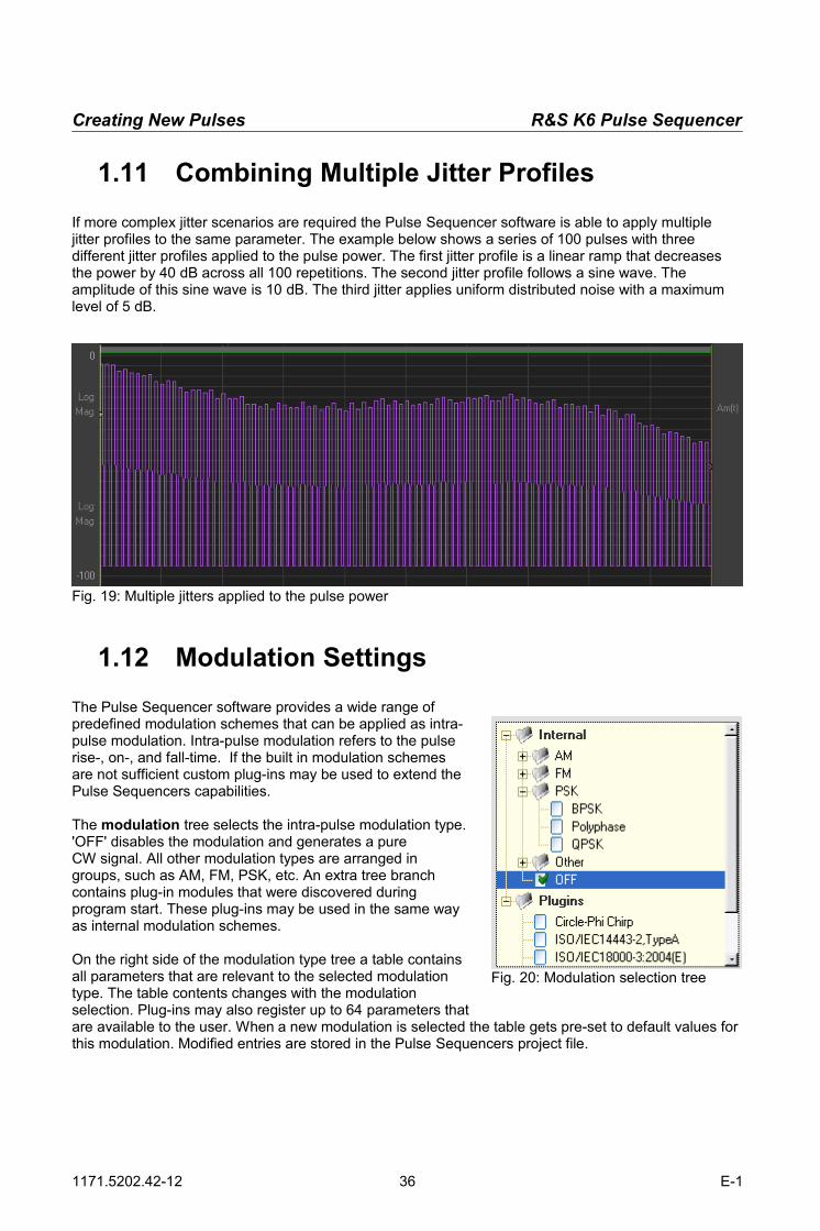
If more complex jitter scenarios are required the Pulse Sequencer software is able to apply multiple jitter profiles to the same parameter. The example below shows a series of 100 pulses with three different jitter profiles applied to the pulse power. The first jitter profile is a linear ramp that decreases the power by 40 dB across all 100 repetitions. The second jitter profile follows a sine wave. The amplitude of this sine wave is 10 dB. The third jitter applies uniform distributed noise with a maximum level of 5 dB.
1.12 Modulation Settings
The Pulse Sequencer software provides a wide range ofpredefined modulation schemes that can be applied as intra-pulse modulation. Intra-pulse modulation refers to the pulserise-, on-, and fall-time. If the built in modulation schemesare not sufficient custom plug-ins may be used to extend thePulse Sequencers capabilities.
The modulation tree selects the intra-pulse modulation type.'OFF' disables the modulation and generates a pureCW signal. All other modulation types are arranged ingroups, such as AM, FM, PSK, etc. An extra tree branchcontains plug-in modules that were discovered duringprogram start. These plug-ins may be used in the same wayas internal modulation schemes.
On the right side of the modulation type tree a table containsall parameters that are relevant to the selected modulationtype. The table contents changes with the modulationselection. Plug-ins may also register up to 64 parameters thatare available to the user. When a new modulation is selected the table gets pre-set to default values for this modulation. Modified entries are stored in the Pulse Sequencers project file.
1171.5202.42-12 36 E-1
Fig. 19: Multiple jitters applied to the pulse power
Fig. 20: Modulation selection tree

R&S K6 Pulse Sequencer Creating New Pulses
The 'Reset' button sets all configuration parameters back to the modulation or plug-in default settings.Out of range items are marked in yellow. Thelimits for each entry are either determined by thebuilt in modulation or in case of a plug-in arerequested from the plug-in at program start.The configuration parameters are very usefulwhen working with plug-ins as they permit thereuse of the same plug-in code with manydifferent configurations.
Some modulation types require data which canbe provided in a table below the modulationselection tree. The table is only active formodulation types that require data. ThePulse Sequencer software provides a wide rangeof internally defined data sources, such aspatterns or PRBS generators.Data bits are drawn starting from the first list entry.Once all bits from this entry are used up thefollowing one provides the data bits. Thismechanism continues until the end of the list isreached. Further data requirements cause the list to wrap around and start over at its beginning.The example above delivers two bits that are set to zero, then 13 bits from a Barker sequence and finally two more zero bits.Pulse Sequencer offers different types of data sources. Random and Pattern draw bits from internal generators whereas the User setting draws bits from data that is provided by the user.The 'Sources' button next to the data source list is used to display the user data editor. This editor is described in the next chapter in detail.
PatternsAll 0 Only zero bits are generatedAll 1 Only one bits are generated1010 Alternating ones and zeros are generatedBarker Codes:
Length Code
3 1 1 0
4 a,b 1 0 1 1 1 0 0 0
5 1 1 1 0 1
7 1 1 1 0 0 1 0
11 1 1 1 0 0 0 1 0 0 1 0
13 1 1 1 1 1 0 0 1 1 0 1 0 1
Barker codes of length 11 and 13 are mainly used in pulse compression radar systems because of their good autocorrelation properties.
1171.5202.42-12 37 E-1
Fig. 21: Modulation parameters
Fig. 22: Setting modulation data

Creating New Pulses R&S K6 Pulse Sequencer
1.13 The Data Source Editor
The Data Source Editor can be invoked from themenu bar 'Project → Data Sources' or by the 'Sources'button on the pulse modulation panel.The tree on the left side lists all available datasources. Clicking on one of the items activates theediting fields on the right side.
New data sources can be added with the 'New' buttonthat is located above the data sources tree. Selectedentries can be removed using the 'Delete' button.Once a new data source is created its contentcan be set-up using the data bits entry field.The number of valid bits are shown on the rightside above the entry field.The entry field evaluates zeros ('0') and ones ('1')as well as numbers in hexadecimal format.Comments can be enclosed in slashes ('/'). Thefollowing overview explains how data isinterpreted.
• All blank characters are ignored• A slash turns the comment field on or off• The sequence #x starts hexadecimal input for the remainder of the line• A new line turns hexadecimal and comment mode off• Ones and zeros are evaluated as single bits
Input Examples:
1100 0100 / comment / 1111 0000 / comment until end of line …
1111 0011 / 101 is not evaluated here /
#xABF0 / 16 bits from hexadecimal numbers /
#x f0 a3 7d 1e / 32 bits
Data sources are available globally within the project. Once a data source is set-up its data is available in all pulses. However, each pulse draws data individually from the data source and there is no possibility to resume data that has not been used up in a previous pulse.
1171.5202.42-12 38 E-1
Fig. 23: Data sources tree
Fig. 24: Data bits editor

R&S K6 Pulse Sequencer Creating New Pulses
6.1 Built-In Modulation Types
AMAM stands for Amplitude Modulation with a single tone.
Parameters:AM Type Standard
LSB
USB
LSB+USB
Regular AM
AM with only lower side band
AM with only upper side band
AM without carrier
Mod Freq [kHz] 0….100.0 MHz Modulation frequency
Depth [%] 0…100 Modulation depth
ASKASK stands for Amplitude Shift Keying. The amplitude of the RF carrier is attenuated for a bit value of zero and remains at full level for bit values of one. The level of attenuation is specified asdepth in percent.
Parameters:Depth [%] 0….100 Modulation depth
Invert yes | no Invert bits
Coding normal
position
Regular ASK, set amplitude level by bit
Each bit is divided into two halfs:
1 = first half active, second half blanked
0 = first half blanked, second half active
1171.5202.42-12 39 E-1

Creating New Pulses R&S K6 Pulse Sequencer
FMFM stands for Frequency Modulation with a single tone.
Parameters:Mod Freq [kHz] 0….25.0 MHz Modulation frequency
Deviation [kHz] 0….300.0 MHz Total deviation
The figure below shows power and frequency versus time. The pulse is set to a modulation frequency of 2 kHz and deviation of 4 MHz. The ARB sample rate is 10 MHz and the total pulse time is 1 ms.
It can be seen that the frequency changes between -Deviation and +Deviation (positive and negative full scale is half the sample rate).
1171.5202.42-12 40 E-1
Fig. 25: FM Modulated Signal

R&S K6 Pulse Sequencer Creating New Pulses
FM StereoThe FM Stereo modulation type creates an analog FM stereo signal according to the ITU-R BS.450-3, chapter 2.2 recommendation (Transmission standards for FM sound broadcasting at VHF).
Parameters:Deviation [kHz] 10 … 100.0 kHz FM Deviation (default: 75 kHz)
Right Tone [kHz] 0.001 … 15.0 kHz Audio tone for right channel
Right Audio Level -1.000 … +1.000 Level multiplier for right audio channel(default: 1.0)
Left Tone [kHz] 0.001 … 15.0 kHz Audio tone for left channel
Left Audio Level -1.000 … +1.000 Level multiplier for left audio channel(default: 1.0)
MUX Pilot Level [%] 0.1 … 20.0 Level of pilot in stereophonic multiplex signal(default: 8-10%)
MUX Audio Level [%] 0.1 … 100.0 Level of audio signals in stereophonic multiplex signal(default: 80%)
The RF signal is created from a carrier that is frequency modulated by a baseband signal, called the 'stereophonic multiplex signal'. The figure below shows the contents of this signal.
The stereophonic multiplex signal contains the sum of the left and right audio channel, a pilot toneof 19 kHz and a 38 kHz carrier that is analog modulated with the audio difference signal.
FSKFSK stands for Frequency Shift Keying. High bits set the frequency to +Deviation whereas low bits set the frequency to –Deviation.
Parameters:Deviation [MHz] 1 HZ….300.0 MHz The deviation from the carrier used for low or high bits
1171.5202.42-12 41 E-1
45 %
22.5 %
10 %
15 19 38 53 kHz
L+R
L-R L-R

Creating New Pulses R&S K6 Pulse Sequencer
FSK(2)FSK stands for Frequency Shift Keying. High bits set the frequency to f1 for a duration of T1 whereas low bits set the frequency to f1 for a duration of T2.
Parameters:f1 [MHz] 0 HZ….300.0 MHz Frequency deviation used for low bits
f2 [MHz] 0 HZ….300.0 MHz Frequency deviation used for high bits
T1 [us] 0....100 ms Time used for low bits
T2 [us] 0....100 ms Time used for high bits
The figure below shows a 1 ms pulse that is modulated by the bit sequence 1100110011. f2 (highbits) is set to 2 MHz andT2 is set to 50 us. F1 (low bits) is set to 4 MHz and T1 is set to 150 us.
This type of FSK is useful if the bit time needs to be adjusted according to the frequency deviation, e.g. to ensure a full period count.
Multi CarrierThe multi carrier modulation creates multiple CW carriers that are equally spaced using a given spacing. In order to reduce the signal peak-to-average ratio is is possible to use random phase offsets when generating the carriers.
Parameters:Spacing [kHz] 1 HZ….100.0 MHz Spacing between carriers
Carriers 2....100000 Number of carriers
Random phase yesno
User random phase to reduce pk-to-av ratioUse start phase zero
1171.5202.42-12 42 E-1
Fig. 26: FSK modulated signal

R&S K6 Pulse Sequencer Creating New Pulses
Multi ToneThe multi tone modulation creates a signal with up to five custom CW frequencies.
Parameters:f1 [MHz] -100 MHz....+100MHz 1st carrier frequency
f2 [MHz] -100 MHz....+100MHz 2nd carrier frequency
f3 [MHz] -100 MHz....+100MHz 3rd carrier frequency
f4 [MHz] -100 MHz....+100MHz 4th carrier frequency
f5 [MHz] -100 MHz....+100MHz 5th carrier frequency
Unused frequencies: value must be set to zero.
FM ChirpThe FM chirp sweeps the RF signal across a set frequency range.
Parameters:RF Bandwidth [MHz] 1 HZ….600.0 MHz The frequency is swept from -BW/2 to +BW/2
Shape ramp upramp downsineexp
exp 10
triangularinv trian
The frequency is ascending linearThe frequency is descending linearThe frequency follows a full sine waveThe frequency is ascending exponentially according to 2.718281828 ^ xThe frequency is ascending exponentially according to 10.0 ^ xThe frequency ascends and then descendsThe frequency descends and then ascends
Polynomial FMThis modulation creates an FM chirp that is generated using a polynomial. The equation below is used to calculate the instantaneous frequency versus time.
f t=s a0a1ta2 t2a3 t
3a4 t4a5t
5
Parameters:Multiplier -106....+106 s
Term 0 -106....+106 a0 (constant offset)
Term 1 -106....+106 a1 (linear term)
Term 2 -106....+106 a2
Term 3 -106....+106 a3
Term 4 -106....+106 a4
Term 5 -106....+106 a5
Term 6 -106....+106 a6
1171.5202.42-12 43 E-1

Creating New Pulses R&S K6 Pulse Sequencer
BPSKBPSK stands for Binary Phase Shift Keying. A bit value of one sets the phase to a definable valuewhereas zero bits leave the phase at zero. An additional phase offset may be used under the general pulse settings to rotate the constellation points.C-BPSK stands for Constant Envelope BPSK.
Parameters:Type BPSK
C-BPSKRegular BPSKConstant Envelope BPSK
Phase [deg] 0.01....180.0 Phase change between 0 and 1
Transition [%] 0....100.0 Time used for transition between phases (C-BPSK only)
Trans Shape cos Transition shape (C-BPSK only)
Coding normaldifferential
no codinguse differential coding
Barker R13, BPSK, 0 % transition time, 45 degees phase offset
Barker R13, C-BPSK, 50 % transition time, 45 degrees phase offset
The transition settings are only required for the C-BPSK modulation type.
1171.5202.42-12 44 E-1

R&S K6 Pulse Sequencer Creating New Pulses
8PSK8PSK stands for 8 Phase Shift Keying. A bit value of one sets the phase to a definable value whereas zero bits leave the phase at zero. An additional phase offset may be used under the general pulse settings to rotate the constellation points.
Parameters:Type 8PSK Regular 8PSK
Rotation [deg] 0.01....360.0 Rotation of constellation from symbol to symbol. Set to 67.5 for EDGE
Gain I 0.01...1.0 Gain for I axis. Use 1.0 for full scale.
Gain Q 0.01...1.0 Gain for Q axis. Use 1.0 for full scale.
Phase Ofs [deg] -180.0...+180.0 Constant phase offsets that rotates the entire constellation.
PolyphasePolyphase modulation is mainly used in Low Probability of Intercept (LPI) radars.
Parameters:Type Frank
P1 CodeP2 CodeP3 CodeP4 Code
Frank CodeP Code
Length 1....200 Code Length
1171.5202.42-12 45 E-1
I
Q
011
110101
111
010
100
001
000

Creating New Pulses R&S K6 Pulse Sequencer
QPSKQPSK stands for Quadrature Phase Shift Keying.
α Angle [deg]
Each sample requires two bits which are mapped using the following constellation.
Bits Based on angle ( α ) For α = 45 degrees00 α/360 * 2 π + ¼ π01 pi - α/360 * 2 π + ¾ π10 -pi + α/360 * 2 π - ¾ π11 -α/360 * 2 π - ¼ π
Parameters:Type QPSK
O-QPSKC-QPSKD-QPSK
Regular QPSKOffset QPSKConstant Envelope QPSKDifferential QPSK
Rotation [deg] 0.0....360.0 Rotation of constellation from symbol to symbol. Set to 45 for π/4 QPSK
Gain I 0.01....1.0 Gain for I axis. Use 1.0 for full scale.
Gain Q 0.01....1.0 Gain for Q axis. Use 1.0 for full scale.
Phase Ofs [deg] -180.0....+180.0 Constant phase offsets that rotates the entire constellation.
Angle [deg] -180.0....+180.0 The angle between the QPSK constellation points and the I axis for an offset = 0.
C-QPSKThis type of modulation is similar to QPSK but transitions from one constellation point to the other happen at constant amplitude, thus, only phase changes occur. The following list shows how data bits are translated into phase changes.
00 - ½ π01 - ¼ π10 + ¼ π11 + ½ π
1171.5202.42-12 46 E-1
I
Q
α
00
1110
01
R&S K6 Pulse Sequencer Creating New Pulses
VSB8VSB8 stands for Vestigial Side Band and is a special type of phase modulation with eight constellation points in a straight line. Three bits are required to form one symbol. Data bits are mapped according to the following table.
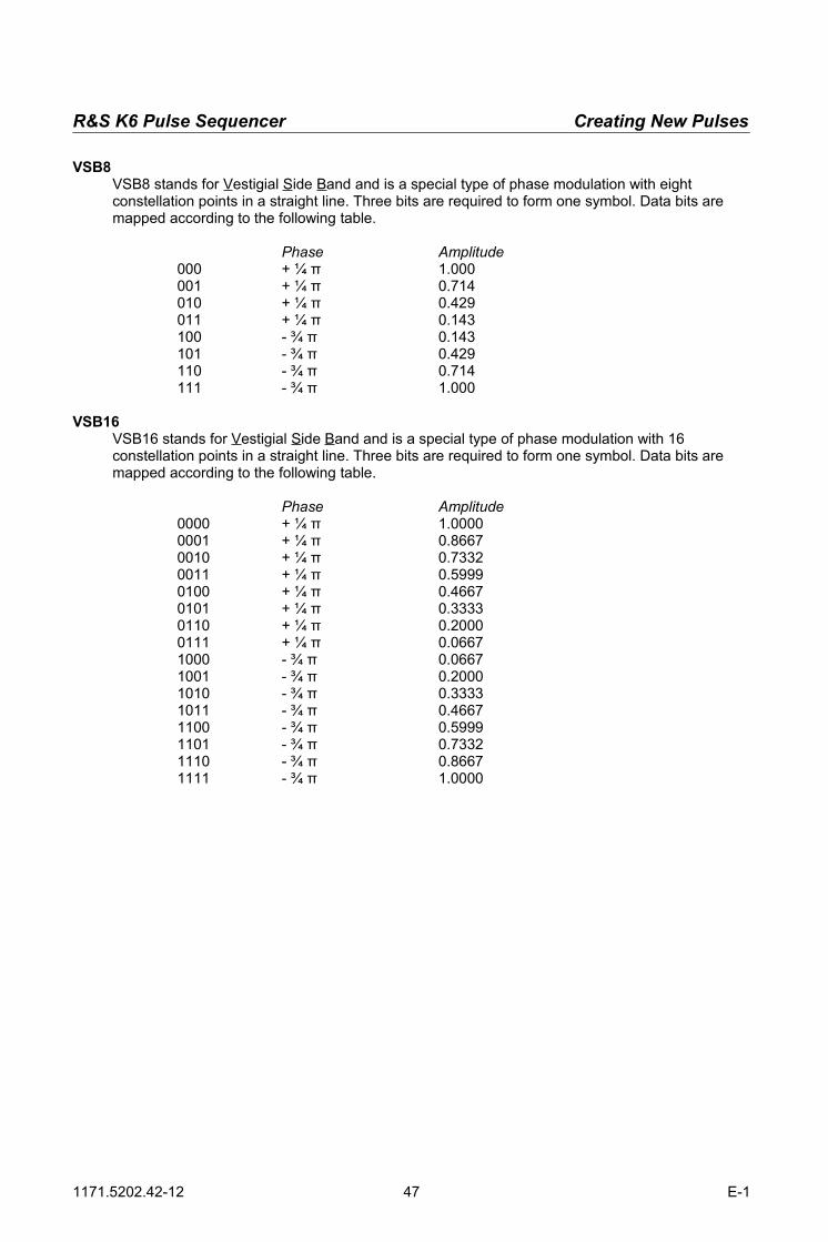
Phase Amplitude000 + ¼ π 1.000001 + ¼ π 0.714010 + ¼ π 0.429011 + ¼ π 0.143100 - ¾ π 0.143101 - ¾ π 0.429110 - ¾ π 0.714111 - ¾ π 1.000
VSB16VSB16 stands for Vestigial Side Band and is a special type of phase modulation with 16 constellation points in a straight line. Three bits are required to form one symbol. Data bits are mapped according to the following table.
Phase Amplitude0000 + ¼ π 1.00000001 + ¼ π 0.86670010 + ¼ π 0.73320011 + ¼ π 0.59990100 + ¼ π 0.46670101 + ¼ π 0.33330110 + ¼ π 0.20000111 + ¼ π 0.06671000 - ¾ π 0.06671001 - ¾ π 0.20001010 - ¾ π 0.33331011 - ¾ π 0.46671100 - ¾ π 0.59991101 - ¾ π 0.73321110 - ¾ π 0.86671111 - ¾ π 1.0000
1171.5202.42-12 47 E-1

Creating New Pulses R&S K6 Pulse Sequencer
Plug-insThe modulation is defined by an external plug-in. Plug-ins are DLL modules that are loaded during program start. They contain the maths that is required for the envelope shaping and the intra-pulse modulation. Examples are bundled with the R&S Pulse Sequencer software.Plug-ins can register up to 64 parameters which become available to the user in the modulation parameters table. This allows the use of the same plug-in in many different configurations.When a pulse is calculated the plug-in is provided with the general waveform settings, such as ARB sample rate as well as the registered variable values. Subsequently the plug-ins maths function is called once for each sample and required to return data in polar coordinates.
6.2 Marker Settings
The markers 1 through 4 can be freely assigned to any section of a pulse by using the check box matrix. Marker information is directly added to the resulting waveform and the marker signal output is therefore synchronous with the waveform playback.A set marker becomes active for the entire number of samples used up for the selected period of time. For example, activating a marker during the rising edge generates an output from the very beginning of the edge until the very end of it (0 % to 100 % level).The same marker can be assigned to multiple sections of a pulse such as rise-time, on-time and fall-time.The example shows that marker 1 is assigned to the rising edge, the on period and the falling edge of a pulse.
Restart activates the marker for the first 10 % of the entire pulse repetition interval.
The marker flag definitions from this matrix are the fundamental marker definitions. When pulses are used in sequences it is possible to further restrict marker signal generation in the sequence editor. However, if a marker is not tied to any pulse section in this dialog it cannot be used in a sequence. In addition, the preferences panel allows to inhibit markers globally. This frees memory that can be used for waveform data instead.
1171.5202.42-12 48 E-1
Fig. 27: Marker settings

R&S K6 Pulse Sequencer Creating Sequences
12 Creating Sequences
A sequence combines a series of pulses with additional information, such asthe ARB sample rate, baseband filters, jitters as well as marker information. Itis therefore required create pulse definitions first and then build thesequences.A new sequence is created by either selecting ‘Create → New Sequence’ fromthe menu bar or clicking the sequence creation button on top of the projecttree (second button from left). In both cases a new sequence is created and itsname set to new-<n>.Clicking on a sequence entry in the project tree opens the sequence editor.The sequence editor panel mainly consists of a table that is populated with the pulse entries used in thesequence. When a new sequence is created the last pulse from the pulse data base is automatically added as the very first item.
A detailed description of the sequence editor follows in the next chapter.
New entries can be added to the list with the 'create new sequence entry' button.This button has multiple functions depending on how it is used.
1. If no entries exist in the table the button adds a new sequence entry.2. If entries exist but none of them is selected the button appends
a new entry at the end of the list. The new entry is a copy of the last list entry.3. If an existing entry is selected the button creates a copy of this entry and
inserts it in the row below.
This button removes a selected list entry from the table.
The buttons move the selected entry one line up or down.
Hide the sequence in the project tree if 'Hide Tree Entries' is selected.
1171.5202.42-12 49 E-1
Fig. 28: One entry in the sequence editor table

The Sequence Editor R&S K6 Pulse Sequencer
13 The Sequence Editor
The sequence editors main control is a table that contains the pulse entries in the order they get processed during the waveform generation. Each line represents one single pulse definition as well as additional information, such as the repetition count, jitter settings and marker mask information.
ItemThe very first field indicates the entry number. All pulse entries are numbered starting at index one. Thiscolumn is only for reference and cannot be edited.
ModeThis field can be toggled between different states that describe how the pulse entry is added to the final waveform. The following options are available.
‘---‘ The entry is appended at the end of the waveform ‘ADD’ The entry is added to the existing waveform starting at the beginning of the previous entry (→ overlay mode) ‘MULT’ The entry is multiplied with the existing waveform starting at the
beginning of the previous entry (→ overlay mode)
Tstart [µs]Indicates the estimated starting time of the pulse entry in microseconds. This number does not take intoaccount any alterations due to jitter. The final value may be different if jitter is applied and is available after the waveform has been created.
Tstop [µs]Indicates the estimated stop time of this entry. The number is read only for regular pulse entries. In case of blank or CW fillers this entry sets the desired point in time.
SamplesThis field contains the required number of samples as an estimation based on the pulse timing and given ARB sample rate. In case the timing is altered by jitter the final number maybe different. Therefore, the final numbers are available after a waveform creation.
1171.5202.42-12 50 E-1
Fig. 29: Sequence editor table

R&S K6 Pulse Sequencer The Sequence Editor
Pulse ObjectThis field selects the pulse definition from the pulse library. Clicking this entry opens a drop down box with all available pulse definitions. In addition, two special entries exist at the top of the list which are called 'fillers'. These entries are no true pulses but act as fillers on the time scale. They either add a blanking period or a CW signal up to a certain point in time and may be used as a synchronization point. Filler entries are highlighted in blue and do not provide any jitter, repetition count or marker options.
RepThis number sets the repetition count for the pulse entry. The default value is one and adds the pulse once to the sequence. Numbers greater than one repeat the pulse multiple times before the next line item gets processed.
Jitter 1,2,3,4These settings define how jitter values are applied. A prerequisite for using these settings is that jitter profiles are defined in the underlying pulse definition.
OFF No jitter is applied Same A jitter value is created and this value is used for all repetitions Individual Jitter values are calculated individually for each of the repetitions Next This entry only makes sense with jitter data provided by an ordered list of values. It reuses the same number for all repetitions but continues reading numbers from the list having been used by the previous line item. Reuse This entry only makes sense if the previous line item uses the same pulse definition. In this case all jitter values from the previous line item are reused. Mseg This entry only makes sense with jitter data provided by an ordered list of values and when working with Multi-Segment waveforms. It uses the Multi-Segment waveform index for taking values from the list.
M1, M2, M3, M4These fields can be cycled through the states 'OFF' → '1ST' → 'LAST' → 'ALL' and are used to mask marker information depending on the pulse repetition. A prerequisite for using these settings is that marker flags are assigned to pulse phases in the underlying pulse definition.
OFF No marker information is added 1ST Maker information is generated for the first pulse out of all repetitions only LAST Marker information is generated for the last pulse out of all repetitions only ALL The marker information is generated for all repetitions
1171.5202.42-12 51 E-1

The Sequence Editor R&S K6 Pulse Sequencer
6.3 General Sequence Settings
A sequence contains not only the order of pulses that are to be used but also general information that isrequired for the waveform generation. Most of these settings are located at the top of the sequence editor dialog.
NameThis field sets the name of the sequence. This name is used in the project tree and identifies the sequence. The sequence names should therefore be unique within a project.
CommentThe comment is optional and added to the final waveform file. This field can be left blank if no comment is required.
CopyrightThe copyright information is optional and added to the final waveform file. This field can be left blank if no copyright information is required.
Sample RateSets the desired ARB sample rate. See the section →Sample Rate Considerations for more details. After changing the clock rate it is required to create the waveform again because the number of samples varies with the sample rate.If the file size is not critical it is suggested to use the maximum possible clock rate for best performance.Please see your instrument manual for details about the maximum possible sample rate of your instrument.
Baseband FilterThe R&S Pulse Sequencer software provides a selection of baseband filters that can be applied to the final waveform. This allows the user to limit the bandwidth of the final waveform output.This function can also be used to simulate the output signal of the instrument by using a low pass filter that is set to the maximum ARB bandwidth of the instrument.
ReportThe button opens the report generation dialog. The report output documents all parameters that were used during the waveform creation and is particular useful if random jitter is applied to parameters.
1171.5202.42-12 52 E-1
Fig. 30: General sequence settings
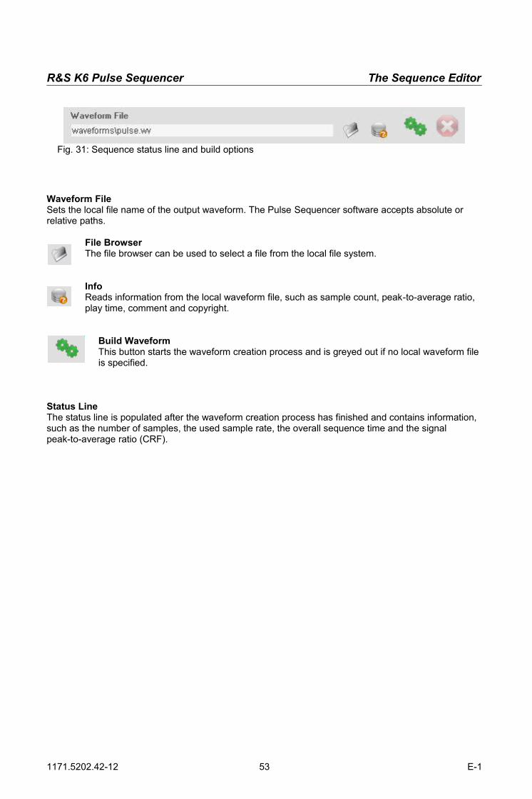
R&S K6 Pulse Sequencer The Sequence Editor
Waveform FileSets the local file name of the output waveform. The Pulse Sequencer software accepts absolute or relative paths.
File BrowserThe file browser can be used to select a file from the local file system.
InfoReads information from the local waveform file, such as sample count, peak-to-average ratio, play time, comment and copyright.
Build WaveformThis button starts the waveform creation process and is greyed out if no local waveform file is specified.
Status LineThe status line is populated after the waveform creation process has finished and contains information, such as the number of samples, the used sample rate, the overall sequence time and the signal peak-to-average ratio (CRF).
1171.5202.42-12 53 E-1
Fig. 31: Sequence status line and build options

The Baseband Filter Dialog R&S K6 Pulse Sequencer
14 The Baseband Filter Dialog
The Pulse Sequencer software can run its waveform output through a baseband filter. Each sequence can use an individual baseband filter configuration but all pulses within a sequence are processed using the same filter. Use the baseband filter button from the sequence editor to open the baseband filter dialog. A green LED next to the baseband filter
button indicates that the filter is active.The baseband filter dialog is divided into three sections. The tree on the left side lists all predefined filtertypes. The middle section defines filter parameters that are required for the selected filter type. The rightside of the dialog is used to import custom filter data if the filter type is set to 'User Data'.
Enable Baseband FilterThe check box enables or disables the baseband filter.
WindowThe window function is multiplied with the filter function and therefore influences the resulting output spectrum.
Cutoff FrequencySets the filters cut-off frequency. For example, a cut-off frequency of 2 MHz results in a total RF bandwidth of 4 MHz.
1171.5202.42-12 54 E-1
Fig. 32: Baseband filter dialog

R&S K6 Pulse Sequencer The Baseband Filter Dialog
Roll Off / BTSome filters such as cosine or root cosine require an additional roll-off factor to determine the excess bandwidth. Gauss filters require the parameter B•T instead of roll-off.
B = filter 3 dB bandwidthT = symbol period
B•T is related to the ARB sample rate before any oversampling is performed. The Pulse Sequencer software estimates the filter bandwidth by the equation f = B • T • sample rate assuming that one symbol corresponds to one single sample.
OversamplingThe Pulse Sequencer allows the user to set an over-sampling factor that permits rescaling the waveform to a target sample count. Marker flags are generally tied to samples and therefore change from one sample to the next. But whenfractional over-sampling factors are used additional samples need to be inserted which causes the marker flag changes to fall in between samples.
TreeThe type of filter used as the baseband filter.
Filter Roll off / B*T
Impulse response
Rectangular
h t =sinc tT ={sin t /T 1
t /T≠0t /T=0
Root Cosine Roll Off
0.001 – 1.000
h t =4απT
cos1α πtT T
4αtsin1−α πt
T 1−4αtT
2
Cosine Roll Off
0.001 – 1.000
h t =sinc tT cosπα tT
1−4αtT 2
Gaussian B*T
0.001 – 1.000
h t =
exp−t2
2δ2 2π⋅δ
δ=ln 2 2π BT
1171.5202.42-12 55 E-1

Report Generation R&S K6 Pulse Sequencer
15 Report Generation
Pulse Sequencer can generate report data during the waveform creation process. This is particularly useful if jitter modifies waveform parameters randomly. By default all report data is appended to a text file in form of columns that are separated by spaces. A header is added on top of each
table that explains the content of each column.The report button in the sequence editor opens the report generation dialog. Report settings are individually set for each sequence. A green LED next to the report button indicates that the report is active for this sequence.Data reporting slows down the waveform creation if many pulses are to be generated because one line of text is added to the report for each pulse.
FormatSets the format of the report data.
OFF No report data is generatedText Data is appended to an ASCII text file<Plug-in> A plug-in is used to process report data
1171.5202.42-12 56 E-1
Fig. 33: Report generation dialog

R&S K6 Pulse Sequencer Report Generation
FileSets the file name for the report data output. New data is always appended at the end of the file. Each sequence can use its own report file.
Pulse Timing parametersThe check boxes in the pulse timing section enable reporting all values that concern the pulse timing. The reported values are the final figures including jitter. The values do not reflect any rounding errors that are caused by a baseband filter re-sampling process because baseband filtering is performed as the final step and using the complete waveform.
FrequencyThe frequency offset from the carrier frequency set for the pulse including any jitter alterations.
PhaseThe pulse start phase including any jitter alterations.
Level (On/Off)The level attenuation set for the pulse including any jitter alterations.
DroopThe level decay during the pulse-on time including any jitter alterations.
FM DeviationThe FM deviation used for the pulse, e.g. for FM chirps.
Start TimeThis figure is the absolute starting point of a pulse rising edge within a waveform.
Sequence Entry No.The line item number in the sequence editor table starting at one for the first item.
FillersThe amount of time that was added by either a CW or blank filler.
Repetition CountThe number of repetitions set for a line item in the sequence editor table.
Repetition NumberIn case multiple repetitions are used for a line item a separate entry is generated for each one of the repetitions. The repetition number starts with one and is increased up to the set number of repetitions.
Multi-Segment No.If a sequence is used as part of a Multi-Segment waveform this entry reports the segment number where the sequence is used. Counting starts at one for the first segment.
1171.5202.42-12 57 E-1

Overlaying Pulse Entries R&S K6 Pulse Sequencer
16 Overlaying Pulse Entries
By default all pulse entries from the sequence editor are processed sequentially and appended to the final waveform. However, under certain conditions it may be desirable to add multiple pulses on a common time scale. The process of adding waveforms is referred to as overlay mode in the Pulse Sequencer software.Each pulse entry within a sequence can be compared to segments on a time line. By default, segments are appended one after the other to this time line. In the overlay mode multiple segments are stacked on top of each other which allows the addition or multiplication of pulse entries. The following figure demonstrates the difference between the default sequential mode and the overlay mode.
Multiple line items of a sequence can be combined to an overlay group. The first item of this group is shown in yellow and defines the length of the entire overlay period (Seg. 1). All subsequent segments are added to the existing data starting at the beginning of the first segment. If the new segment is shorter than the length of the overlay group the remainder is left blank. Longer segments are truncated. The Pulse Sequencer software allows using blank or CW fillers as the first segment of an overlay group and therefore allows to set a defined end point for the entire group. Besides adding waveforms to each other it is also possible to multiply waveforms. This is useful for blanking signals, e.g. when simulating radar waveforms.
1171.5202.42-12 58 E-1
Seg. 1 Seg. 2 Seg. 3 Seg. 4
Default: One segment after the other
Seg. 1
Overlay: Segments are added or multiplied
Seg. 2 Blank
Seg. 3
Seg. 4
truncated part
Seg. 1+2+3

R&S K6 Pulse Sequencer Overlaying Pulse Entries
The screen shot below shows an example of an overlay of three pulse entries.
Line item 1 sets the entire time of the overlay group to 3 ms by creating a blank filler signal. The following items (2,3,4) are added to this blank signal starting at t = 0. Jitter is used to shift the items 2 and 3 slightly in time. The result is a series of 3 pulses.
6.4 Overlay Application Examples
6.4.1 Radar Antenna TX, RX Simulation
For radar receiver testing it might be desirable to generate signals that contain the transmit pulse as well as multiple receive pulses. In this case one sequence entry could be used to generate multiple repetitions of the TX pulse as they would be transmitted during one turn of a radar antenna. The following line items are set to overlay and add the receive pulse with a time delay, frequency offset or phase shift caused by jitter profiles. This allows generating complex pulse return patterns as they might be caused by multiple reflections or antenna side lobes.
6.4.2 Sector Blanking
Many radar systems blank their signals in certain sectors to avoid interference with other equipment. In order to simulate blanking one line item of the sequence could be set up to generate multiple repetitionsof a pulse as it would result from one antenna turn without blanking. The next line item is set to overlay and multiplies a single on-off pulse that generates the blanking sector.
1171.5202.42-12 59 E-1
Fig. 34: Sequence with overlay entries

The Sequence View R&S K6 Pulse Sequencer
17 The Sequence View
After an ARB waveform is created from a sequence the resulting I/Q data can be viewed using the sequence view panel. This panel displays the final I/Q output as contained in the output waveform.The sequence view tab is only available if a waveform was created successfully. Selecting different entries from the project tree invalidates data and the sequence viewer becomes unavailable again.The sequence viewer is divided into multiple areas. The large upper area shows various signals, such as I and Q, amplitude, phase or frequency versus time. The lower left side is the I/Q constellation or density plot, depending on the number of samples that are analysed. The lower right area shows an FFT spectrum of the entire waveform or the currently viewed section (view port).
1171.5202.42-12 60 E-1
Fig. 35: Sequence view panel

R&S K6 Pulse Sequencer The Sequence View
6.5 Time Domain Display
The upper area is the time domain display and shows a signal versus time. This area is also referred to as the view port because it defines the section of the data looked at. The way data is presented in the view port changes depending on the number of samples looked at. If the number of samples is greater than the number of screen points the view mode shows straight lines between the minimum and maximum value that falls within one screen point. This ensures that the full envelope is always visible. If the number of samples is lower than the number of screen points the Pulse Sequencer software shows individual sample points and connecting lines in between. The two pictures below demonstrate the difference when looking at a sine wave.
A set of navigation buttons are placed above the view port area. These buttons provide general navigation functions, such as moving to waveform locations, zooming in and out as well as zooming to a marked area.
Move to the very beginning of the waveform.
Move left by half the display length
Move right by half the display length
Slider Reposition within the trace
Zoom out by a factor of two
Zoom in by a factor of two around the centre of the view port
Zoom to the boundaries set by the two cursor lines
1171.5202.42-12 61 E-1
Fig. 36: Zoomed out Fig. 37: Zoomed in

The Sequence View R&S K6 Pulse Sequencer
Two controls on the right side above the view port select the way data is represented and toggle the marker reading display. The different data representations are discussed below.
I/Q ViewSets the view port to display the I and Q signal versus time. Both signals use a linear scale in the range between -1.0 to +1.0.
This view shows the baseband output of the instrument as it would be accessible through the I and Q output connectors.
Polar ViewThe polar view displays the magnitude and phase angle of the signal versus time. The upper magnitude curve is scaled linear in the range from 0 to 1. The lower curve shows the phase in the range from -π to +π . A phase change is equivalent to a rotation at constant radius in the constellation diagram. The phase graph wraps around at the positive or negative borders
1171.5202.42-12 62 E-1
Fig. 38: I/Q waveform view of a chirped signal
Fig. 39: Polar view of a BPSK modulated signal

R&S K6 Pulse Sequencer The Sequence View
Log Mag ViewThis view shows the pulse envelope in the logarithmic scale (20 log[sqrt(I2+Q2)] ). The scale ranges from 0 dB down to -100 dB and covers the full 16 bit dynamic range of the vector signal generators internal ARB. This view mode can be utilized to see very low signal levels that would not be visible in the linear scale. The graphical representation of the envelope in the logarithmic scale can be compared to a scale typically used in Spectrum Analyzers in zero spanmode (logarithmic scale).
F(t), Am(t) ViewThis view shows the pulse envelope in logarithmic scale as well as the instantaneous signal frequency versus time. The frequency scale ranges from -Fs/2 to +Fs/2 with Fs being the ARB sampling rate.
1171.5202.42-12 63 E-1
Fig. 40: Logarithmic view of pulse magnitudes
Fig. 41: Magnitude and frequency view of a series of chirped pulses

The Sequence View R&S K6 Pulse Sequencer
6.6 Marker (Cursor) Functions
The view port provides two vertical cursor lines that maybe used for marker measurements or for defining the zoomrange. Each cursor line provides its absolute position intime and the sample number that it is positioned on. Inaddition, the distance between the two lines is calculatedand shown as time difference and frequency.The marker readings can be enabled using the 'Mkr ON'button.
6.7 I/Q Plane
The Pulse Sequencer software provides an I/Q plane display in the lower left area of the sequence viewpanel. The amount of data analysed and displayed in the I/Q plane is the signal part visible in the view port (time domain view). The representation of I/Q plane data depends on the amount of samples analysed. For a large number of samples a density plot is used with a colour scale from blue to yellow that indicates how often a sample is located at a certain I/Q constellation point. If the number of samples is relatively small the constellation points are displayed with interconnecting lines in between.In both view modes a small cursor is available and can be moved using the mouse. The cursor shows the current I and Q value as well as magnitude and phase.
I/Q Plane Vector DiagramThe vector diagram shows individual I/Q data points with connecting lines in between. This view is only available for a smaller amount of data because a large number of data points would create too many points and hide signal details. In the I/Q plane each sample must be displayed individually because averaging or min-max detection would create false data points. The grey circle marks the envelope level of 1.0. Clipping occursif this limit is exceeded and therefore the circle indicates the maximum safe signal range.
I/Q Plane Density PlotIf a larger number of samples is analysed the Pulse Sequencer software automatically switches to a density plot. The density plot shows the probability at which I/Q points occur in the waveform. The display is relative to the point with the maximumprobability (set to 1.0). In pulsed signals with long idle times thisis often the origin of the coordinate system. The colour scale is logarithmic and ranges from 1.0 (bright yellow) down to a probability of 10-4 (dark blue). The scale on the left side is used as legend and explains the relationship between colours and probability.
1171.5202.42-12 64 E-1
Fig. 42: Marker controls
Fig. 43: I/Q vector diagram
Fig. 44: I/Q density plot

R&S K6 Pulse Sequencer The Sequence View
6.8 FFT Spectrum
The Pulse Sequencer software displays theFFT spectrum of either the entire or afraction of the signal in the lower right areaof the sequence view. The FFT uses alogarithmic scale scale between 0 dB and-100 dB. The level scale is relative andautomatically set based on the maximumsignal amplitude. The frequency scalecovers the ARB sample rate set for thesequence and ranges from -Fs/2 to +Fs/2.The amount of data analysed can beselected between the entire waveform andthe view port content only. The amount ofdata that can be analysed in the FFTdisplay is limited. For very large waveformsit might therefore be required to restrict theFFT display to the view port section only. The FFT view remains blank if the amount of data exceeds theFFT length limit.
1171.5202.42-12 65 E-1
Fig. 45: FFT spectrum display

The Transfer Panel R&S K6 Pulse Sequencer
18 The Transfer Panel
Once an ARB waveform is created from a sequence it can be transferred to the instrument. The transferpanel is used to perform this task. It also provides basic instrument control features that are required forwaveform playback and signal routing.The panel is divided into three major sections that slightly differ in colour. The top section displays the local waveform file name (source file) as well as information about the target instrument.The middle section sets the target ARB and defines signal routing as well as basic RF parameters.The lower section contains buttons that reset the instrument and start the waveform transfer.
Local WaveformThis field contains the local waveform file name. The name is automatically filled in during the process of building a waveform from a sequence. This field cannot be edited and is blanked once a different entry from the project tree is selected.
Target InstrumentThe field contains the target instruments VISA resource string. This field is automatically filled in when an instrument is selected on the Instrument Manager panel. The name of the target instrument is cleared if the instrument becomes unavailable.
1171.5202.42-12 66 E-1
Fig. 46: Transfer panel

R&S K6 Pulse Sequencer The Transfer Panel
Instrument Manager ButtonThis button opens the Instrument Manager panel which is used to select the target instrument.
K6 LicensesOnce an instrument link is set-up the K6 license count is determined by evaluating the instruments option string. Your instrument requires at least one K6 license for playing back an ARB waveform that isgenerated by the Pulse Sequencer software.Two-path instruments may be equipped with a single or two K6 licenses. In case of only one license thewaveform can either be played in path A or B. Two K6 licenses allow the playback of two waveforms simultaneously in path A and B.The R&S WinIQSIM2TM software can be used to combine multiple Pulse Sequencer waveforms to a multi carrier or Multi-Segment waveform. In this case the license requirements mentioned above apply to the WinIQSIM2TM output file.
Use source file nameThe Pulse Sequencer software automatically uses the waveform file name as set in the sequence editorand shown in the upper panel section. It combines this file name with the target directory set under 'Options → Preferences → Waveform Creation' to an absolute file name used as target on the instrument. The Pulse Sequencer software uses the Linux or Windows path based on the selected target instrument. This is the simplest and recommended setting for transferring the waveform to the instrument.
Manual entryThe target file name for the waveform transfer can be specified by the user. This allows using the same file name for all generated waveforms, e.g. for testing purpose. In addition, an instrument file browser button allows the simple selection of an instrument target directory.When using the manual entry field it is recommended to provide an absolute path, e.g. 'D:\MyFiles' for aWindows based instrument.On Linux based instruments the path depends on hardware options. A valid standard path is /var/<instrtype>, e.g. /var/smbv for an R&S SMBV100A. If the hard disk option is available the standard path is /hdd regardless of the instrument.
Baseband A,BThe baseband button changes its state between 'ignore', 'load' and 'load/run' with each mouse click. Use this button to define the action that is to be performed when the 'Transfer and Configure' button in the lower panel section is pressed.
RoutingThis selection can be used on two-path instruments to define the routing of the baseband signals. A single path instrument only provides path A and uses a fixed routing.
RF ControlsThe RF controls set the RF frequency, the output level and the output state of path A or B. The check boxes define if the frequency or level value is applied or be left unchanged. If neither frequency nor level is activated the entire RF section remains unchanged. The state of the RF output signal is set by the ON/OFF button.
Transfer and ConfigureThe button sends the selected waveform file(s) to the instrument and configures both pathsas required.
ResetResets the instrument to a default state.
1171.5202.42-12 67 E-1

Multi-Segment Waveforms R&S K6 Pulse Sequencer
19 Multi-Segment Waveforms
The Pulse Sequencers project tree lists all Multi-Segment waveforms that belong to the current project. Clicking on a Multi-Segment waveform entry opens the editor panel.New MSWs are created by selecting 'Create → New Multi Segment' from the menu bar. This adds a new MSW description to the project tree and opens the MSW editor panel.Multi-Segment waveforms contain a set of regular ARB waveforms with additional control information that permits arbitrary jumps between these segments.Assembling Multi-Segment waveforms is an automated process and consists of the following steps.
Create one a waveform from a sequence description Transfer the resulting waveform file to instrument Delete the local waveform file Append the waveform to the MSW description Repeat the above steps for all waveform segments Build the Multi-Segment waveform on the instrument Optionally build a sequencer list for the Multi-Segment waveform Configure the instrument for the MSW playback
All the above steps can be executed automatically by the Pulse Sequencer software.
6.9 General MSW Settings
NameSets the name of the Multi-Segment waveform. This name is used for reference in the project tree and does not affect the waveform itself. Use unique names to identify the MSW in the project tree.
CommentAn optional comment field may be used to add explaining text to the MSW definition.
1171.5202.42-12 68 E-1
Fig. 47: General MSW settings

R&S K6 Pulse Sequencer Multi-Segment Waveforms
6.10 MSW Editor
The Multi-Segment waveform editor mainly consists of a table that defines the sequences which are contained in the Multi-Segment waveform file. Additional controls are provided to create or delete entries as well as for changing their order.
Target NameThe target name defines the name of the Multi-Segment waveform file on the instrument. When the MSW is created on the instrument the Pulse Sequencer uses the path set in the project preferences dialog (Menu 'Options → Preferences → Project Settings').
New EntryCreates a new line item in the MSW editor. Each line item references a sequence from the project tree. All line items are processed and appended to the MSW in the order they are listed. If a line item is selected the button creates a copy of the selection and inserts it after the selected line. If no line item is selected a new entry is appended at the end of the list.
Delete EntryThe button deletes a selected line item from the list. Deleting a line item does only affect the MSW and not the sequence that is removed.
Move Entry UpThis button moves a selected line item up by one position. The first line item cannot be movedfurther up and remains at its position.
Move Entry DownThis button moves a selected line item down by one position. The last item cannot be moved further down and remains at its position.
NoThis column contains the zero based index number of the waveform segment. The index number is read only and only provided for reference.
1171.5202.42-12 69 E-1
Fig. 48: MSW editor

Multi-Segment Waveforms R&S K6 Pulse Sequencer
RepThe repetition count can be set if the Multi-Segment waveform is operated in sequencer mode. In this case a segment can be repeated multiple times. The entry can either be a numeric value in the range between 1 and 65536 or a random value. For random values the following expression must be used:
rand(<min value>,<max value>,<step size>)
SequenceThis column selects the sequence that is used for this Multi-Segment waveform entry. All sequences that are part of the project are available. Additionally, a blank filler waveform can be selected and adds blank signal until a definable point of time.
SamplesThe sample column is read only and contains the final sample count of the sequence once it has been created. The sample count can only be determined during calculation because jitter may change the waveform length.
Tstart
This column is read only and contains the final start time of the entry if sequencing is enabled.
Tstop
This column is read only for regular sequences and contains the stop time of the entry if sequencing is enabled. For blank filler segments this entry can be edited and contains the desired stop time in µs.
1171.5202.42-12 70 E-1

R&S K6 Pulse Sequencer Multi-Segment Waveforms
6.11 Building Multi-Segment Waveforms
The right side of the MSW editor contains two sections. The upper section provides settings that are required for the MSW generation process. Since MSWs are generated directly on the instrument it is required to set-up the instrument link before attempting to build the MSW.
ModeThe build mode can be selected between 'Sequencer' and 'Regular'. In the sequencer mode an additional sequencer list is created and the entire Multi-Segment waveform is played automatically. Thismode is useful if waveforms with long blank times need to be created. In this case blank fillers may be used and the Pulse Sequencer Software automatically determines an optimum waveform length and repetition count for the blanks segment. The regular mode adds the waveform segments but the user must switch the segments either via the user interface or via remote control.
Clock RateThe Clock Rate setting sets the target sample rate when the MSW is created on the instrument. If ‘unchanged’ is selected the instrument leaves the sample rates of the individual segments unchanged. When the MSW is played back the sample rate will therefore change from segment to segment. If ‘highest’ is selected the instrument re-samples all segments to the highest sample rate used in the MSW. The ‘user’ setting sets a target sample rate to a fixed value. All segments are re-sampled to this target sample rate during the MSW creation process. Building a MSW takes more time when re-sampling is required.In sequencer mode this setting is forced to 'user' and a target clock rate must be provided.
LevelDuring the MSW creation the instrument can also adjust the level of MSW sections. The 'unchanged' option does not change the level and adds segments unchanged to the final MSW. The 'equal RMS' option rescales the segment to ensure that all segments use the same RMS signal level.
BB PathThis entry selects into which path the final MSW is loaded.
1171.5202.42-12 71 E-1
Fig. 49: MSW build settings
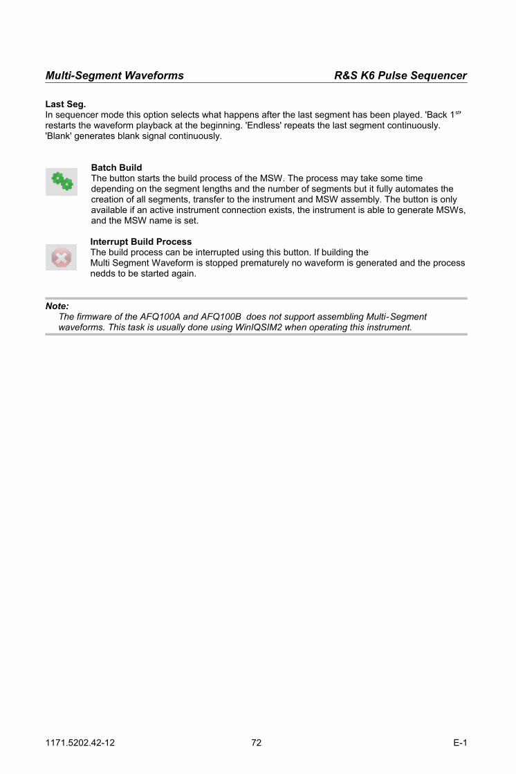
Multi-Segment Waveforms R&S K6 Pulse Sequencer
Last Seg.In sequencer mode this option selects what happens after the last segment has been played. 'Back 1st' restarts the waveform playback at the beginning. 'Endless' repeats the last segment continuously. 'Blank' generates blank signal continuously.
Batch BuildThe button starts the build process of the MSW. The process may take some time depending on the segment lengths and the number of segments but it fully automates the creation of all segments, transfer to the instrument and MSW assembly. The button is only available if an active instrument connection exists, the instrument is able to generate MSWs,and the MSW name is set.
Interrupt Build ProcessThe build process can be interrupted using this button. If building the Multi Segment Waveform is stopped prematurely no waveform is generated and the processnedds to be started again.
Note: The firmware of the AFQ100A and AFQ100B does not support assembling Multi-Segment waveforms. This task is usually done using WinIQSIM2 when operating this instrument.
1171.5202.42-12 72 E-1
R&S K6 Pulse Sequencer Multi-Segment Waveforms
6.12 Operating Multi-Segment Waveforms
The lower right section of the MSW editor panel contains controls that are used to remote control the instrument when playing back Multi-Segment waveforms. An active instrument link is required in order to operate these controls.
Trigger ModeThe trigger mode defines the basic trigger operation mode. If 'Auto' is selected the instrument automatically plays back a section or multiple sections of a Multi-Segment waveform. In the 'Single' mode the waveform or segment is only played once. The Extended Trigger Mode defines if only a section or the entire MSW is affected by the trigger setting.
Extended Trigger ModeThis entry selects if only a segment or the entire MSW is affected by the trigger signal. 'Same' sets the instrument to replay the selected segment based on the selected trigger mode. 'Next' advances to the next MSW entry with each trigger event. 'Seamless' is only available if all segments use the same sample rate and plays one segment after the other without any interruption.
Trigger SourceSelects the trigger source for the MSW playback. Valid choices are 'Internal', 'Exxt1', 'Ext2' and 'Path2'.
Next SegmentSelects the segment that gets selected when the 'Apply' button is pressed.
Delay [samples]Sets a trigger delay in samples between a trigger event and the start of the MSW playback.
ApplyThis button sends all of the above settings to the instrument. It also selects the current waveform segment. During the apply process the RF output of the instrument is turned off. This eliminates the accidental output of an RF signal.
TriggerThis button becomes active if an instrument connection is set up and the trigger source is set to 'Internal'. If the trigger mode is set to 'Single' and 'Next' this button is used to manually start the playback of the next segment.
1171.5202.42-12 73 E-1
Fig. 50: MSW operation controls

RF Lists R&S K6 Pulse Sequencer
20 RF Lists
RF Lists only affect the RF section of the instrument. These lists can be used independently of any typeof modulation and provide a hopping functionality across the entire instrument frequency and level range. The benefit of using RF Lists over remote control is mainly speed since RF Lists use precomputed instrument settings that allow for fast setting changes.Typical switching times are in the range of 400 µs. Please see the instrument manual for further information about operating RF Lists.The Pulse Sequencer software contains RF Lists as part of a project and simplifies the creation process.New RF Lists are created by calling 'Create → New RF List' from the menu bar. This adds a new RF List entry to the project tree and opens the RF List editor.
NameSets the name of the RF List. This name is used for reference in the project tree and does not affect thelist itself. Use unique names to identify the RF List in the project tree.
CommentAn optional comment field may be used to add explaining text to the RF List definition.
New RF Lists have zero length and contain no items. As a very first step it is therefore required to define the list length which creates the necessary blank entries in the list editor table.
Set LengthSets the RF List length to the given number of list items. New items are automatically set to 1 GHz and -30 dBm. Please consult your instrument manual for the maximum RF List length of your instrument.
Dwell TimeSets the dwell time for the RF List playback. The dwell time sets the duration of each frequency and level pair when the list is played back.
1171.5202.42-12 74 E-1
Fig. 51: General RF List settings
Fig. 52: RF List settings
R&S K6 Pulse Sequencer RF Lists
The RF List editor provides a table that contains the frequency and level pairs of the RF List. An entry can be edited by double clicking into the field. In addition, limits can be set to mask items that fall within the limit range. These items are marked green in the list.
DeleteThe button deletes a selected line item from the RF List.
AddInsert a new entry into the RF List.
Move Entry UpThis button moves a selected line item up by one position. The first line item cannot be moved further up and remains at its position.
Move Entry DownThis button moves a selected line item down by one position. The last item cannot be moved further down and remains at its position.
ImportThe import button reads list entries from an ASCII text file. The frequency and level pairs must be separated in columns.
ExportThe export button writes the RF List data to a text file. The file contains a header as well as thefrequency and level pairs. The last column compares the frequency and level values against the set limits and marks the line items with pass (P) or fail (F) indicators.
Project : FCC 15.407 / FCC-060-96A Author : Rohde & SchwarzDate : Nov 11, 2008Version : 2.0.0
RF List : Random Hop List
Lev min : 0.00Lev max : 0.00F min : 5.592500
1171.5202.42-12 75 E-1
Fig. 53: RF List editor

RF Lists R&S K6 Pulse Sequencer
F max : 5.607500
Entry Frequency [MHz] Level [dBm] Limit===================================================== 1 5.300000 0.00 F 2 5.474000 0.00 F 3 5.304000 0.00 F 4 5.676000 0.00 F 5 5.336000 0.00 F 6 5.373000 0.00 F 7 5.711000 0.00 F 8 5.597000 0.00 P 9 5.720000 0.00 F
The Pulse Sequencer software provides a dialog that is used to populate the RF Lists with default values. Frequency and level can be controlled separately.
ModeThe mode selection defines how the Pulse Sequencer software populates the RF List. The option 'All same' uses the set value for all list entries. 'Uniform' fills the list with random data. The minimum andmaximum value as well as a step size can be defined. The option 'Unique Random' populates the list with random values but it is ensured that each random value only appears once.
FillThe button fills in the frequency or level values.
Once the RF List is populated its contents can be compared against two sets of limits. Values that are within the limit range are marked green. The limits do not affect the RF List playback.
Min / MaxThe values define the minimum and maximum limit range for level or frequency. Any change is effectiveimmediately and matching items are marked in green.
1171.5202.42-12 76 E-1
Fig. 54: Filling an RF List
Fig. 55: RF List limit settings

R&S K6 Pulse Sequencer RF Lists
The Pulse Sequencer software keeps RF List data as part of the project. However, this data is not the final RF List because these lists can only be created directly on the instrument. The process of creating the RF List therefore requires an instrument connection and an instrument that supports RF Lists.
The panel at the bottom of the RF List editor provides all controls that are required to transfer the data to the instrument and build the list.
Remote List FileSet the file name of the RF List (.lsw) on the instrument. If no pathname is provided the Pulse Sequencer software uses the default path that are defined in the project settings dialog . This dialog is available from the menu bar under 'Options → Preferences → Project Settings'.
Remote File SelectionThe button opens a remote file browser which allows to select a pathname or file on the instruments file system. This dialog can also be used to copy files from the instrument to the local file system.
PathSelects the target path for the RF List in case a two-path instrument is connected.
Start TransferThe button transfers the list data and builds the RF List on the instrument.
ResetThis button resets the instrument to the default state.
Please NoteOnce all RF List data is copied to the instrument and the 'Activate' option is enabled the instrument starts a learning process. This learning mechanism involves a baseband pre-set to a sine wave test signal. RF Lists should therefore be transferred to the instrument before the baseband is configured.
1171.5202.42-12 77 E-1
Fig. 56: RF List transfer controls

The Log Panel R&S K6 Pulse Sequencer
21 The Log Panel
The log panel records status messages that the Pulse Sequencers software generates. The log panel isalways available as the right most tab in the main application window. All log messages are read only but data can be marked and copied to the clipboard using Ctrl-C. The log panel output is useful to determine the cause for an error or unexpected program behaviour. It also displays all SCPI communication between the Pulse Sequencer software and the instrument.
1171.5202.42-12 78 E-1

R&S K6 Pulse Sequencer Plug-in Modules
22 Plug-in Modules
Plug-ins can be used to extend the Pulse Sequencers built in modulation capabilities. Some example plug-ins are provided with the software as binary and source code and may serve as a starting point for own applications. The following sections discuss the plug-in mechanism in more detail and provide information on the programming interface.
6.13 The Plug-in Mechanism
Plug-ins are Microsoft Windows DLLs and need to be located in the sub directory Plugins under the installation directory of the Pulse Sequencer software. This sub directory is searched during program start and useful plug-ins are loaded into memory for later use.Every plug-in needs to provide a certain range of functions to identify itself and perform the calculations required for the intra-pulse modulation. These functions are described further in the programming API section of this manual. In addition, plug-ins may register a set of configuration parameters with the Pulse Sequencer software. These parameters become part of a pulse definition and may be used as variables inside the plug-in. This allows to reuse plug-ins with different configurations.Plugins can also be used for report generation during the waveform creation process. This mechanism allows the user to create custom report data, e.g. to fill in EXCEL spread sheets with the pulse parameters that were used.
6.14 The Programming API
The following paragraph lists all functions that need to be provided by the plug-in. It explains the interface as well as the functionality that needs to be provided by each function.
6.14.1 Get Type
void __declspec(dllexport) __cdecl mod_type (char szModType[1024]);This function is mandatory. It provides a string that is used to determine the purpose of the plug-in.
Parameters:szModType out “modulation” the plug-in is used for intra pulse modulation
“report” the plug-in is used for report generation
6.14.2 Get Version
void __declspec(dllexport) __cdecl mod_ver (char szModVer[1024]);This function is mandatory. It shall return the version string of the plug-in.
Parameters:szModVer out Format: X.Y.Z where X,Y and Z are numeric values, e.g.
2.34.01
1171.5202.42-12 79 E-1

Plug-in Modules R&S K6 Pulse Sequencer
6.14.3 Set Name
void __declspec(dllexport) __cdecl mod_name (char szModName[1024]);
This function is mandatory. It provides the Pulse Sequencer software with the name of the plug-in. The name serves multiple purposes. It is used to reference the plug-in from a pulse descriptions and it is used in the project tree to identify the plug-in. Particularly, the first statement requires that plug-in names are unique and do not change at a later time. If the plug-in name changes the pulse definition becomes invalid and the pulse cannot be calculated any more.
Parameters:szModName out Plug-in Name. Must not be an empty string. Name must be
unique.
6.14.4 Get Comment / Explanation
void __declspec(dllexport) __cdecl mod_comment (char szModComment[4096]);
This function is mandatory. It is used to return explaining text regarding the plug-in functionality.
Parameters:szModComment out String with explaining text. Multiple lines are possible. May be
an empty string.
6.14.5 Get Author
void __declspec(dllexport) __cdecl mod_author (char szModAuthor[1024]);
This function is mandatory. It is used to return information about the author of a plug-in.
Parameters:szModAuthor out String with author information. May be an empty string.
6.14.6 Get Error
void __declspec(dllexport) __cdecl mod_error (char szModError[1024]);
This function is mandatory. It is called from Pulse Sequencer whenever another function returns false and may return additional error information.
Parameter:szModError out Explaining error text. It is suggested to clear any internal
error text after is it queried through this function.
1171.5202.42-12 80 E-1

R&S K6 Pulse Sequencer Plug-in Modules
6.14.7 Initialization
int __declspec(dllexport) __cdecl mod_init (void);
This function is used to initialize the plug-in. It is called once after the plug-in is loaded into memory andmay set-up internal variables.
Return:true The initialization completed successfullyfalse Error during the initialization. The plug-in is removed from memory.
6.14.8 Shutdown
void __declspec(dllexport) __cdecl mod_shutdown (void);
This optional function is called when the main application terminates and may be used to clean up previously allocated memory. Errors are not evaluated any more since the plug-in shutdown happens ata relatively late stage during the Pulse Sequencer termination.
6.14.9 Setup Parameters
void __declspec(dllexport) __cdecl mod_setparam ( const char *szType, void *pData );
This function is mandatory. It is called multiple times just before a pulse calculation starts and provides the plug-in with all required information.
szType pData Type Bytes Purposetrise integer 4 Sample count for rising edgeton integer 4 Sample count for on-timetfall integer 4 Sample count for falling edgesrate double 8 ARB sampling rate [Hz]levon double 8 Level during on-time, range 0 … 1.0levoff double 8 Level during off-time, range 0 … 1.0levdroop double 8 Level droop during on-time, range 0…1.0mbits char 10001 Bits used for modulation, string,
max. 10000 ASCII ‚1’ or ‚0’done NULL Last data was sent. Configuration is completefilename string 255 File name of report fileen_pdelay integer 4 Enable pulse delay time for reporten_prise integer 4 Enable pulse rise time for reporten_pon integer 4 Enable pulse on time for reporten_poff integer 4 Enable pulse off time for reporten_pprfpri integer 4 Enable pulse PRF or PRI for reporten_fofs integer 4 Enable frequency offset for reporten_phofs integer 4 Enable phase offset for reporten_levon integer 4 Enable level attenuation 'On' for reporten_levoff integer 4 Enable level attenuation 'Off' for reporten_levdroop integer 4 Enable level droop for reporten_fmdev integer 4 Enable FM deviation for reporten_startt integer 4 Enable pulse start time for reporten_seqno integer 4 Enable sequence entry number for reporten_filler integer 4 Enable filler time for reporten_repcnt integer 4 Enable repetition count for reporten_repno integer 4 Enable number of repetitions for reporten_msegno integer 4 Enable multi segment number for report
1171.5202.42-12 81 E-1
Plug-in Modules R&S K6 Pulse Sequencer
It is not required to take any action inside this function nor is a return value required. It is up the author of the plug-in what to do with the provided information.If information needs to be evaluated the function should compare the strings provided in szType againstthe names listed above. In case of a match the pointer pData needs to be type cast into the appropriate data type and the value read.
6.14.10 Set Values
void __declspec(dllexport) __cdecl mod_setvalue ( const char *szType, void *pValue );
This function receives report data during the waveform creation process. It must be used to collect this data and write all relevant report data when the 'finishentry' option is called.
szType pData Type Bytes Purposeinitreport NULL Start a new report, open files etc.initentry NULL Start of a new entry, initialize etc.set_seqname string 1024 Set the sequence nameset_comment string 4096 Set the sequence commentset_filename string 1024 Set the sequence file nameset_clock double 8 Set the sequence ARB sampling rateset_pdelay double 8 Set pulse delay time for reportset_prise double 8 Set pulse rise time for reportset_pon double 8 Set pulse on time for reportset_poff double 8 Set pulse off time for reportset_pprfpri double 8 Set pulse PRF or PRI for reportset_fofs double 8 Set frequency offset for reportset_phofs double 8 Set phase offset for reportset_levon double 8 Set level attenuation 'On' for reportset_levoff double 8 Set level attenuation 'Off' for reportset_levdroop double 8 Set level droop for reportset_fmdev double 8 Set FM deviation for reportset_startt double 8 Set pulse start time for reportset_seqno double 8 Set sequence entry number for reportset_filler double 8 Set filler time for reportset_repcnt double 8 Set repetition count for reportset_repno double 8 Set number of repetitions for reportset_msegno double 8 Set multi segment number for reportfinishentry NULL End of current entry, write data to reportclosereport NULL End of report generation, close files etc.endreport NULL As above but do not quit
6.14.11 Plug-in Modulation Engine
int __declspec(dllexport) __cdecl mod_engine ( double *dAM, double *dPhase, int iActSample);
This function is mandatory. It is the core function of the plug-in and transforms samples into I/Q data.Parameters:
dAM out Amplitude, range 0 ... 1.0dPhase out Phase, range –Pi ... +PiiActSample in Sample number. The number always starts at zero with
the very first sample of the rising edge.
1171.5202.42-12 82 E-1

R&S K6 Pulse Sequencer Plug-in Modules
Return:TRUE Calculation was successfulFALSE Error during calculation. Pulse Sequencer subsequently calls the error
string function and terminates any further calculation. It is required that this function returns useful numbers for amplitude and phase.
1171.5202.42-12 83 E-1
Plug-in Modules R&S K6 Pulse Sequencer
6.14.12 Plug-in Modulation Engine 2
int __declspec(dllexport) __cdecl mod_engine _2(char *pcMkr,double *dAM, double *dPhase, int iActSample);
This function is optional and can be used instead of the classing modulation engine. It is the core function of the plug-in and transforms samples into I/Q data.
Parameters:pcMkr out Marker datadAM out Amplitude, range 0 ... 1.0dPhase out Phase, range –Pi ... +PiiActSample in Sample number. The number always starts at zero with
the very first sample of the rising edge.
Return:TRUE Calculation was successfulFALSE Error during calculation. Pulse Sequencer subsequently calls the error
string function and terminates any further calculation.
It is required that this function returns useful numbers for amplitude and phase.
1171.5202.42-12 84 E-1

R&S K6 Pulse Sequencer Plug-in Modules
6.14.13 Query Plug-in Configuration Parameters
int __declspec(dllexport) __cdecl mod_getconf (int iIndex, char szType[256], char szName[256],void *pDefaultVal, void *pMin, void *pMax);
This function is optional. It may be used to register configuration parameters with the Pulse Sequencer software.
Parameter:iIndex in Index number of parameter, starting at zeroszType out parameter data type identifierszName out name string associated with parameterpDefaultVal out pointer to default valuepMin out pointer to minimum valuepMax out pointer to maximum value
For the default, minimum and maximum value settings the Pulse Sequencer software provides the function with a pointer that could hold up to 1024 bytes. The functions needs to type cast this pointer to the required data type.
Available Data Types:szType Data Type Bytes Precision PurposeDBL double 8 3 double precision valueDBL6 double 8 6 double precision valueINT integer 4 0 integer valueBOOL integer 4 0 boolean value (yes, no)STR string 255 0 zero terminated string
1171.5202.42-12 85 E-1
Plug-in Modules R&S K6 Pulse Sequencer
6.14.14 Setting Plug-in Configuration Parameters
int __declspec(dllexport) __cdecl mod_setconf ( int iIndex, void *pDat);
The function is optional but needs to exist if plug-in parameters were registered with the Pulse Sequencer software. It is used to set configuration parameters before a pulse calculation is started. All configuration values are referenced to by the index that was used when requesting parameters from the plug-in.
Parameters:iIndex in Index of configuration parameter, starting at zeropDat in Data from Pulse Sequencer. The pointer needs to type
casted into the correct data type.
Return:true Parameter was set successfully.false An error occurred setting the parameter. Pulse Sequencer does
subsequently query the plug-in error string and stop all further processing.
1171.5202.42-12 86 E-1
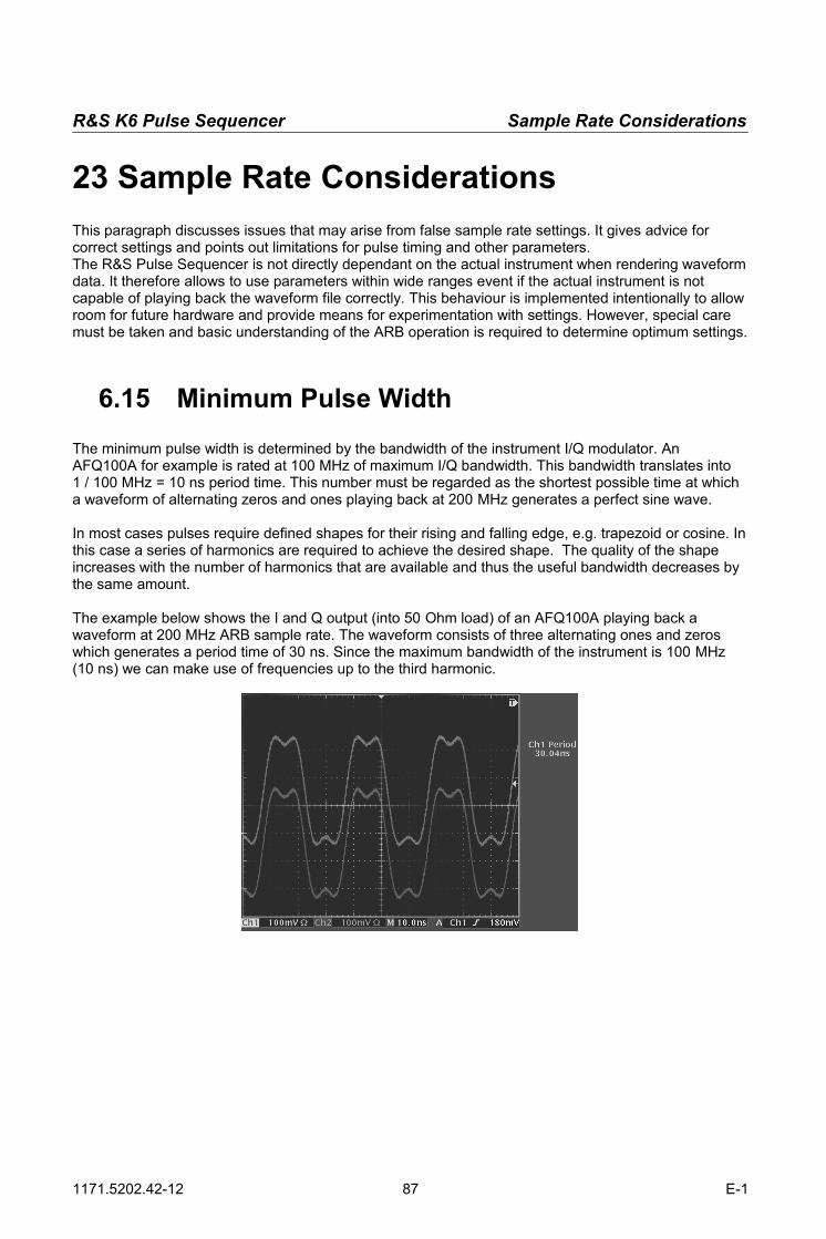
R&S K6 Pulse Sequencer Sample Rate Considerations
23 Sample Rate Considerations
This paragraph discusses issues that may arise from false sample rate settings. It gives advice for correct settings and points out limitations for pulse timing and other parameters.The R&S Pulse Sequencer is not directly dependant on the actual instrument when rendering waveformdata. It therefore allows to use parameters within wide ranges event if the actual instrument is not capable of playing back the waveform file correctly. This behaviour is implemented intentionally to allowroom for future hardware and provide means for experimentation with settings. However, special care must be taken and basic understanding of the ARB operation is required to determine optimum settings.
6.15 Minimum Pulse Width
The minimum pulse width is determined by the bandwidth of the instrument I/Q modulator. An AFQ100A for example is rated at 100 MHz of maximum I/Q bandwidth. This bandwidth translates into 1 / 100 MHz = 10 ns period time. This number must be regarded as the shortest possible time at which a waveform of alternating zeros and ones playing back at 200 MHz generates a perfect sine wave.
In most cases pulses require defined shapes for their rising and falling edge, e.g. trapezoid or cosine. Inthis case a series of harmonics are required to achieve the desired shape. The quality of the shape increases with the number of harmonics that are available and thus the useful bandwidth decreases by the same amount.
The example below shows the I and Q output (into 50 Ohm load) of an AFQ100A playing back a waveform at 200 MHz ARB sample rate. The waveform consists of three alternating ones and zeros which generates a period time of 30 ns. Since the maximum bandwidth of the instrument is 100 MHz (10 ns) we can make use of frequencies up to the third harmonic.
1171.5202.42-12 87 E-1

Sample Rate Considerations R&S K6 Pulse Sequencer
The figure shows a Fourier series of a square wave and can be described by the following equation:
f x =4π
∑n=1,3 ,5 ,. . .
∞1nsin π nxL
It can be seen that even providing the 7th harmonic does not generate a very good square wave. This basic maths should be taken into consideration when designing very short pulses or considering fast rise or fall times.
6.16 Timing Error
Timing is a discrete number when dealing with ARBs where the clock rate defines the granularity on thetime axis. An AFQ100A for example is specified at a maximum ARB sample rate of 300 MHz. This maximum sample rate results in a timing granularity of 1 / 300 MHz = 3.333 ns. R&S Pulse Sequencer computes the number of samples from the timing figures as well as the clock rate setting.
Example: The rising time is set to 25 ns and the ARB sample rate is set to 300 MHz. The number of samples is calculated as 25 ns / 3.333 ns = 7.50075. The R&S Pulse Sequencer uses seven samples leaving an error of 25 ns – 7 * 3.333 ns = 1.669 ns. If a sample rate of 200 MHz was used the granularity would be 5 ns and the timing error therefore zero.
1171.5202.42-12 88 E-1

R&S K6 Pulse Sequencer Sample Rate Considerations
6.17 Dynamic Range
The full dynamic range of the R&S Vector Signal Generators ARBs provide a total of 16 bits for both, the I and the Q signal. However, the effective number of bits is less due too multiple reasons. The following example explains the effect of the carrier leakage through the I/Q modulator and points out possible solutions on how to achieve higher dynamic ranges.
The instrument specification of the R&S SMU200A lists a typical carrier leakage value of -65 dBc for theI/Q modulator. This means that even if there is no ARB signal applied to the I/Q modulator and the output level is set to 0 dBm we still see a carrier at -65 dBm at the generator output. In some applications higher dynamic ranges may be required and additional effort is required to achieve this dynamic range.
Adding a frequency offset:If the receiver bandwidth is narrow it is possible to add a frequency offset to the pulse definitions used in the R&S Pulse Sequencer software. The device under test would then see a carrier leakage of typical-65 dBc outside of its receiver bandwidth.
Using pulse modulation in parallel:The R&S Pulse Sequencer software allows the flexible generation of marker signals. It is possible to tie a marker signal to the active part of the pulse and route this signal to the pulse modulator input of the vector signal generator. The pulse modulator in the R&S SMU200A offers an on/off ratio of greater than70 dBc.
1171.5202.42-12 89 E-1
65 dBc
carrier frequency outside receiver bandwidth
DUT
generator
output
receiver bandwidth
wanted signal

Index R&S K6 Pulse Sequencer
Index88PSK..................................................................................44AAbbreviations.......................................................................6Alpha..................................................................................55AM......................................................................................38Amplitude Modulation........................................................38Amplitude Shift Keying.......................................................38arbitrary envelope..............................................................25Arbitrary Pulse Envelope...................................................24ASK....................................................................................38AWGN................................................................................27BBandwidth..........................................................................27Barker Codes.....................................................................36Baseband...........................................................................67baseband filter....................................................................55Baseband Filter............................................................52, 54Batch Build.........................................................................72Binary Phase Shift Keying.................................................43BPSK..................................................................................43BT.......................................................................................55Build Waveform..................................................................53CC-BPSK..............................................................................43C-QPSK.............................................................................46Clock Rate..........................................................................71Comment................................................................52, 68, 74Constant Envelope BPSK..................................................43Copyright............................................................................52Creating New Pulses.........................................................22Cursor.................................................................................64cursor lines.........................................................................64Cutoff Frequency................................................................54DD-QPSK.............................................................................46Data Source Editor.............................................................37Default Path.......................................................................17Delay Time.........................................................................23Density Plot........................................................................64Droop..................................................................................26Dwell Time.........................................................................74Dynamic Range..................................................................90EExtended Trigger Mode.....................................................73FFall Time............................................................................23Features...............................................................................7FFT.....................................................................................65FFT Spectrum....................................................................65File Browser.......................................................................53Filler....................................................................................51FM......................................................................................39FM Chirp............................................................................42FM Stereo..........................................................................40Frank Code........................................................................44Frequency Modulation.......................................................39Frequency offset................................................................26Frequency Offset................................................................26Frequency Shift Keying......................................................40FSK..............................................................................40, 41GGPIB...................................................................................20HHardware Requirements....................................................10hidden entries.....................................................................18
Hotline................................................................................91II/Q Plane............................................................................64I/Q View..............................................................................62Importing Data....................................................................25Installation..........................................................................10Instrument Configuration....................................................11Instrument Link...................................................................20Instrument Manager...........................................................67Instrument Manager...........................................................20Introduction..........................................................................7JJitter....................................................................................28KK6 Licenses........................................................................67LLAN....................................................................................20LGPL..................................................................................92Linear Ramp (Jitter)...........................................................31Local Waveform.................................................................66Log Droop..........................................................................26Log Mag View....................................................................63Log Panel...........................................................................79Log Window.......................................................................15MMarker Settings..................................................................48Markers..............................................................................17Migrating............................................................................14Modulation..........................................................................35Modulation Settings...........................................................35Modulation Types...............................................................38Multi Carrier........................................................................41Multi Segment Waveform Library......................................18Multi Tone..........................................................................42Multi-Segment Waveforms.................................................68Multiple Jitter Profiles.........................................................35NNew Project........................................................................19New Pulse..........................................................................19New Sequence...................................................................19Normal Distribution.............................................................30OO-QPSK.............................................................................46Off Time.............................................................................24On Time.............................................................................23Open Source Acknowledgement.......................................92Overlaying..........................................................................58Overlaying Pulse Entries....................................................58Oversampling.....................................................................55PP Code...............................................................................44Peak Envelope Power........................................................16peak to average.................................................................16PEP....................................................................................16Phase.................................................................................26Phase Shift Keying.............................................................44Plug-in Author....................................................................81Plug-in Comment...............................................................81Plug-in Modules.................................................................80Plug-in Name.....................................................................81Plug-in Version...................................................................80Plug-ins (Modulation).........................................................48Polar View..........................................................................62Polynomial FM...................................................................42Polyphase..........................................................................44PRI / PRF...........................................................................24product ID...........................................................................20Project Settings..................................................................16Project Tree........................................................................18Pulse Library......................................................................18Pulse Width........................................................................88
1171.5202.42 90 E-1
R&S K6 Pulse Sequencer Index
QQPSK.................................................................................45Quadrature Phase Shift Keying.........................................45RRelative Phase...................................................................26Release Notes......................................................................8Report.................................................................................52Report Generation.............................................................56Reset..................................................................................67RF Controls........................................................................67RF List Library ...................................................................18RF Lists..............................................................................74Rise Time...........................................................................23Roll Off...............................................................................55Routing...............................................................................67Rules List (Jitter)................................................................33SSample Rate................................................................52, 88Scan GPIB.........................................................................21Scan LAN...........................................................................21Sequence Editor.................................................................50Sequence Library...............................................................18Sequence View..................................................................60Shape (Interpolated) (Jitter)...............................................32Sine (Jitter).........................................................................31Software Requirements.....................................................12Staircase (Jitter).................................................................32Start Phase........................................................................26TTables (Jitter).....................................................................34Target Instrument...............................................................66Temporary Files.................................................................16Time Domain Display.........................................................61Timing Error.......................................................................89Transfer Panel....................................................................66Trigger Mode......................................................................73Trigger Source...................................................................73UUniform Distribution...........................................................30USB....................................................................................20USB remote control............................................................20VValue List...........................................................................32Value List (Ordered) (Jitter)...............................................32Value List (Uniform) (Jitter)................................................32Vector Diagram..................................................................64vendor ID............................................................................20Vestigial Side Band............................................................47view port.............................................................................61VISA...................................................................................20VISA Resource String........................................................20VSB16................................................................................47VSB8..................................................................................47WWaveform File....................................................................53Waveform Information........................................................53ZZoom in..............................................................................61Zoom out............................................................................61
1171.5202.42 91 E-1


![Sequencer 1, Sequencer 2 or Drum - medias.arturia.net · —Sequencer 1, Sequencer 2 or Drum SHIFT + [>>] = Extend sequence SHIFT + Knob 1 = Offset value for all active steps ...](https://static.fdocuments.in/doc/165x107/5b87086c7f8b9aa0218be152/sequencer-1-sequencer-2-or-drum-sequencer-1-sequencer-2-or-drum-shift.jpg)