Prospects of THz Pulse Generation with mJ- L l E d 100 MV ...

Pulse-Based THz Electronics
EITP05 – Nanoelectronics (vt 2020)

1
Outline
• Motivation
– Wireless bandwidth
• Resonant Tunnelling Diode (RTD)
– Signal generation
– THz potential
– High-rate wireless communications
• Integrated Antennas
– Size matters
– Substrate modes
– Monolithic integration (wireless = no wires)
• Appliations
- High-rate wireless communications
- Radar
• Commercialisation
– Acconeer AB (www.acconeer.com)

2
THz Signal Generation
The THz Technology Gap
• Optical sources above 1 THz
• Direct generation below 1 THz
– Transistor technology
– Diode technology
• Multiplication from lower
frequencies
A combined approach with III-V
Transistors and Tunnel Diodes

3
Resonant Tunnelling Diode (RTD)
• Double barrier structure in conduction band
• Zero bias
– Bound state at energy above fermi level
– No net current
• Small forward bias
– Collector potential drops
– Small net injection from emitter
• Forward bias ~ peak
– Bound state aligned with emitter carriers
– High current
• Forward bias > peak
– Bound state drops below emitter
– Scattering assisted conduction
• Forward bias >> peak
– Thermionic emission through/over barriers

4
Resonant Tunnelling Diode (RTD)
• Double barrier structure in conduction band
• Zero bias
– Bound state at energy above fermi level
– No net current
• Small forward bias
– Collector potential drops
– Small net injection from emitter
• Forward bias ~ peak
– Bound state aligned with emitter carriers
– High current
• Forward bias > peak
– Bound state drops below emitter
– Scattering assisted conduction
• Forward bias >> peak
– Thermionic emission through/over barriers

5
1.92 THz Signal Generation
Oscillation up to 1.92 THz in Resonant Tunneling Diode by Reduced Conduction Loss
T. Maekawa, H. Kanaya, S. Suzuki, and M. Asada
• Increased maximum frequency to 1.92 THz (0.4 µW) in RTD
• 12 µm integrated slot-antenna (lens aperture)
• Reduced conduction loss in antenna fabrication process
Maekawa et al., Appl. Phys.
Express, (9), 2016

6
Wavelet Generator
Startup
Decay
VG
+
Vout
-
di/dtLv ·
t
VG
Egard et al IEEE MWCL2009
Adding Functionality to the Diode
7
RTD/MOSFET Process Flow
- MBE grown wafers
AlAs/InGaAs/InAs/
InGaAs/AlAs RTD
- HSQ Dummy Gate
- InGaAs/InP MOVPE
regrowth
- Gate formation
- Removal of InP
- Contact formation
- RTD etching
- Contact formation

8
Wavelet Generator
The MOSFET is used to switch the oscillator current
The inductance is given by a coplanar waveguide (CPW) stub
Lt=22 pH
C=4.5 fF/µm2
A=2.2x22 µm2
gmin=-120 mS
9
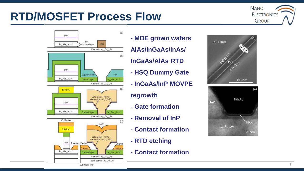
60 GHz Wavelets: Control of Pulse Width and
Position
60 GHz Wavelet Generator for Impulse Radio Applications - Egard et al. 9
74 ps
181 ps
280 ps
383 ps
Input pulse length170 mVpp after de-embedding

10
60 GHz Wavelets: 25 ps Control Pulses
60 GHz Wavelet Generator for Impulse Radio Applications - Egard et al. 10
Wavelet generatortriggered by 25 ps
input pulse
Initial and final part controlled by
capacitive load
L Ohlsson et al Electronics Letters 2015

11
Emission from l/4 antennas
III-V MOSFET Oscillators on Antennas
L Ohlsson et al IEEE MWCL 2014
Emission of waveletsfrom physically smallantenna
Antenna adds pulse distortion

12
60 GHz Communication
• 2 Gpulses/s on-off keying at 60 GHz
2020-03-0460 GHz Wavelet Generator for Impulse Radio Applications - Egard et al.
• 100 ps pulse length, 162 mVpp with losses
embedded

13
A 15-Gb/s Wireless On-Off Keying Link
BER < 10-5 @ 10 Gbps up to 1.5 m
BER < 10-3 @ 15 Gbps up to 1.5 m
Ohlsson et al IEEE Access 2014
2x10⁹ switches
per datapoint

14
OOK Wireless Communications
A 15-Gb/s Wireless ON-OFF Keying Link
• Up to 20 Gb/s OOK at 1.5 m link distance
Ohlsson et al., IEEE
Access, (2), 2014

15
Motivation
802.11
f = 2.4 GHz
BW = 0.1 GHz 802.11
f = 5 GHz
BW = 0.8 GHz
802.15
f = 60 GHz
BW = 7 GHz
Shannon channel capacity
C = B * log2 ( 1 + S / N)
B: bandwidth, S: signal power,
N: noise power
Federal Communications Commission
(FCC) spectrum allocations for the US

16
OOK Wireless Communications
High-Speed Error-Free Wireless Data Transmission Using a Terahertz Resonant Tunnelling Diode
Transmitter and Receiver
S. Diebold, K. Nishio, Y. Nishida, J.-Y. Kim, K. Tsuruda, T. Mukai, M. Fujita, T. Nagashima
• On-off keying (OOK) wireless transmission (10 cm) of 4K video (6 Gbps) at terahertz frequencies
• RTD front-ends at transmitter and receiver with 6G-SDI interfaces
• 286 GHz signal generated by RTD biasing according to digital data
• Demodulation by using RTD as detector (non-linear characteristics)
• Error-free transmissions up to 9 Gbps and operation up to 12 Gbps
S. Diebold et al., Electronics
Lett., (52), 2016

17
Radar: Human Hand Reflection Measurements
S. Heunisch et al IEEE AWPL 2019
Radar cross-section
sheel=-29.5 dBsm
sfinger=-30.6 dBsm
Use of pulse train “Coded Waveform”

18
Human Hand Reflection Measurements
L. Ohlsson Fagher et al IEEE Sensors Letters 2019
Real time tracking of hand and finger movements
Pulsed coherent radar => Low power consumption

19
Signature Classification
2160 measurements from 2 persons
12 gestures, Convolutional Neural Network (ResNet50)
60/40% training/validation split => 99.5% accuracy
L. Ohlsson Fagher et al IEEE Sensors Letters 2019

20
From Research to Nasdaq
A phonecall from SSF …
One mail from a radar compay…
Success with SSF/VINNOVA competition
Collaboration with LU Innovation
Recruitment from industry (Mårten Öbrink)
Investment from Almi
Engagement of local network

Lars Ohlsson Fhager 21Nanoelectronics Group, Lund University
GRUNDEN TILL ACCONEER
En idé: Pulsade oscillatorer
Tvärvetenskap: Nanoteknik och IT
Drivande forskare: Entreprenörer
Industriellt nätverk: Telekom

Lars Ohlsson Fhager 22Nanoelectronics Group, Lund University
GRUNDEN TILL ACCONEER
En idé: Pulsade oscillatorer
Tvärvetenskap: Nanoteknik och IT
Drivande forskare: Entreprenörer
Industriellt nätverk: Telekom

PROPRIETARY AND CONFIDENTIAL
2007
System level demonstrator
successfully tested
First prototype
2012
2014
2016
2017
Commercial product
Ready for production:
First design wins
First purchase orders received
2018Commercial ramp up
Research project in Nanoelectronics
at LTH
Company founded with
support from Lund University
Road to commercialisation

24
Summary
• Motivation
– Wireless bandwidth
• Resonant Tunnelling Diode (RTD)
– Signal generation
– THz potential
• Integrated Antennas
– Size matters
– Substrate modes
– Monolithic integration (wireless = no wires)
• Applications
– High-rate wireless communications
– Radar
• Commercialisation
– Acconeer AB (www.acconeer.com)

Lars Ohlsson Fhager 25Nanoelectronics Group, Lund University
Mm-Wave (30-300 GHz) RTD-MOSFET
0.2 mm
MOSFET
RTD
Egard et al., IEEE EDL, 2012

Lars Ohlsson Fhager 26Nanoelectronics Group, Lund University
RTD-MOSFET Pulse Generation Dynamics
• MOSFET used to switch in/ disconnect RTD
• Low bias
– RTD switched up towards peak, G > 0
– Only bias transients in inductor, v = L di/dt
• Higher bias
– RTD switched into NDR region, G < 0
– Oscillation starts
Ohlsson, Fey, Wernersson, Electronics Letters, 2015
Lars Ohlsson Fhager 27Nanoelectronics Group, Lund University
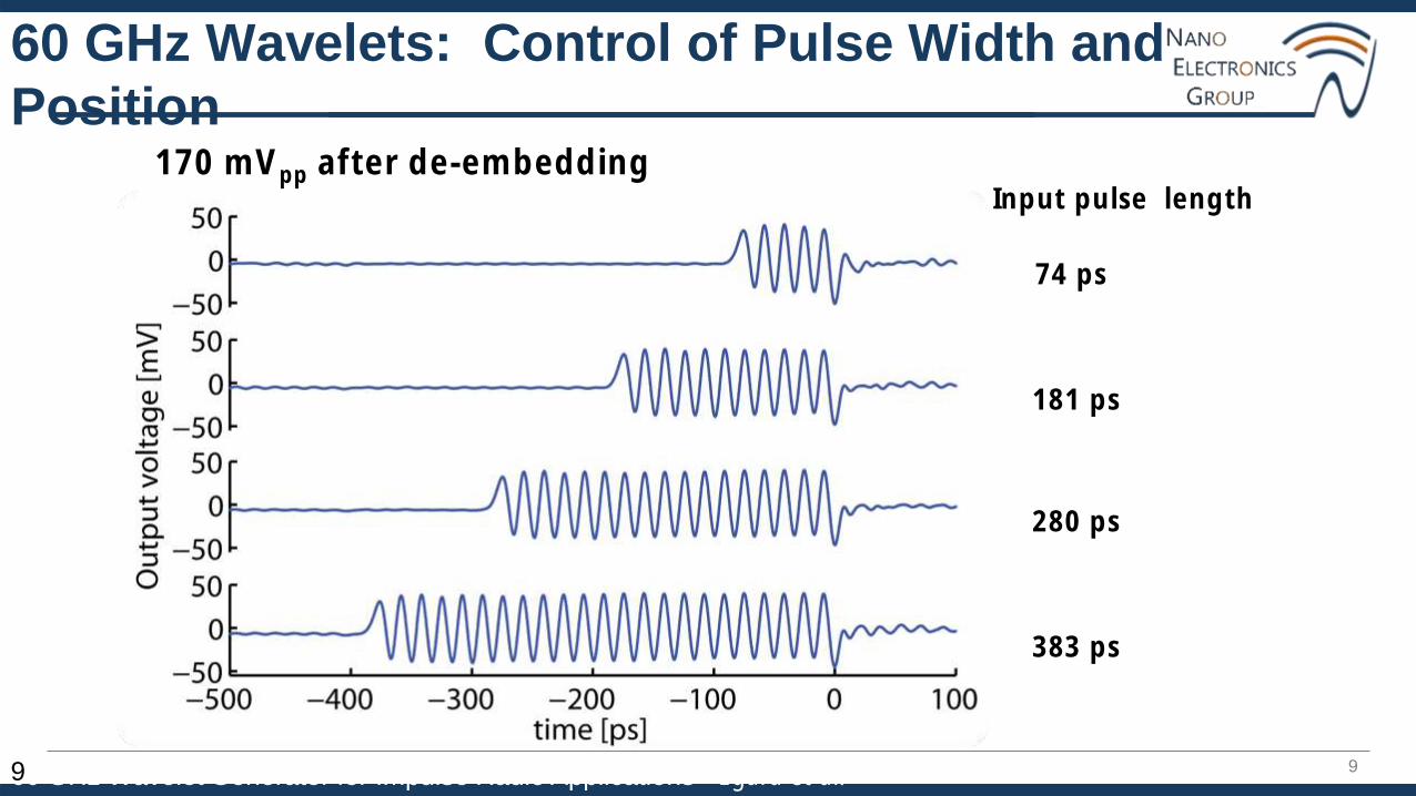
The GTD Pulse Generator
62 GHz, 100 ps long
56 GHz, 160 ps long
Digital control signal

Lars Ohlsson Fhager 28Nanoelectronics Group, Lund University
2 Gpulses/s OOK @ 60 GHz
• 100 ps pulse length
• 162 mVpp
• 59 GHz centre frequency

Lars Ohlsson Fhager 29Nanoelectronics Group, Lund University
2.08 Gpulses/s TH-PPM @ 60 GHz
• 46 ps pulse length
• 148 mVpp
• 62 GHz centre frequency

Lars Ohlsson Fhager 30Nanoelectronics Group, Lund University
Different Bands = Different Antennas
• Longwave to THz (size matters)
Grimeton
(Varberg,
Sweden)
17,2 kHz
telegraph
Acreo THz bolometer
In between:
mm-Wave (30-300 GHz)

Lars Ohlsson Fhager 31Nanoelectronics Group, Lund University
What Radiates, and Why?
• The Antenna Function
– Couple energy
– IV to EM-wave (Transmitter)
• Example: Dipole Antenna
– V projected to E-field
– Electrically large
– Charge imbalance
• ”Half-wave” is enough
– L=1,3,5... x λ/2

Lars Ohlsson Fhager 32Nanoelectronics Group, Lund University
Antenna (de-)Evolution
• Where did the antenna go?
f~1 GHz
λ~30 cm
WWII
”Walkie-talkie”
80’s
00’s
Smaller, Inefficient Antennas
(+ screen, processing, etc.)
= Power Drained Quickly

Lars Ohlsson Fhager 33Nanoelectronics Group, Lund University
Patch Antenna
• Compact
– Easy to integrate
• Easy to Fabricate
– Milling or lithography
• Thin Substrate
– h<<λ
– Not possible at
high frequency!
h<<λ

Lars Ohlsson Fhager 34Nanoelectronics Group, Lund University
Modes in the Substrate
• Electrically Large Substrate
– h~λ
• Mode = Resonant Pattern
– e.g. EM waveform
• Substrate Absorbs Energy
– May dominate over free-space radiation
• Unpredictable Scaling
– New radiation mechanisms
Babakhani et al.
h~λ

Lars Ohlsson Fhager 35Nanoelectronics Group, Lund University
Efficient Millimeter-Wave Antenna?
• Conventional Antenns are Inefficient and Hard to Fabricate
– Substrate is significantly thick
– Scaling don’t allow milled antenna
– On-chip antenna ”radiates” into substrate
• Solution
– Design a resonant mode for radiation
Don’t struggle against the physics,
let it do the job for you instead!

Lars Ohlsson Fhager 36Nanoelectronics Group, Lund University
Dielectric Resonator Antenna (DRA)
• Utilise an electromagnetic mode for radiation
• 50 Ω chip antenna on carrier substrate
– 98% radiation efficiency at 60 GHz
60 GHz
Slot-fed DRA

Lars Ohlsson Fhager 37Nanoelectronics Group, Lund University
DRA Equivalent Circuit Model
• Transmission line with resonator coupling

Lars Ohlsson Fhager 38Nanoelectronics Group, Lund University
From Research to Enterprise
• Lund University
– High-speed communication
– Spectroscopy
– Pulse scattering, etc.
• Acconeer AB (founded winter 2011/12)
– Security screening, material qualification
– Domestic robots
– Portable devices
www.acconeer.com

Name/ context 39

40
Different Pulse Generator Topologies
Lund Approach
Opportunity for Low-Power Operation
Established Approaches

Lars Ohlsson Fhager 41Nanoelectronics Group, Lund University
Motivation
USB 3.0
5 Gbps
WiFi 802.11n
Up to 600 Mbps
HDMI 2.0
Up to 18 Gbps
WiFi Direct
250 Mbps
Bluetooth 3.0
25 Mbps

Lars Ohlsson Fhager 42Nanoelectronics Group, Lund University
Applications at 60 GHz and Above
• Applications
– Wireless HDMI
– Synchronization
– Radar
– Imaging
– Localisation
North America, Korea (7 GHz)
Australia (3.5 GHz)
Europe, Japan (7 GHz)
60 GHz
62.9 GHz59.4
64 GHz57
66 GHz59
Frequency

Lars Ohlsson Fhager 43Nanoelectronics Group, Lund University
Benefits of Nanotechnology
• Potential to improve system performance using III-V technology
– Faster devices, higher gain, lower energy consumption, better power handling, etc.
• Other approaches for signal generation and detection
– Quantum diodes, TFETs, etc.

Lars Ohlsson Fhager 44Nanoelectronics Group, Lund University
Impulse Radio at 60 GHz
• 60 GHz band is unlicensed (but not unregulated)
• Robust – Simple modulation
– OOK, on-off keying
– PPM, pulse position modulation
• High bit rate – Utilises alot of bandwidth
– 7 GHz bandwidth available
• Limited range – Allows reusage of spectrum
– Pathloss, proportional to propagated wavelengths
– 80 dB pathloss @ 60 GHz (4 meters) as compared to
52 dB pathloss @ 2.4 GHz
• Small form factor - Wavelength is 5 mm @ 60 GHz
– Antennas, typically ~½ wavelength
– Inductors, typically << wavelength
Free space path loss at 4 m

Lars Ohlsson Fhager 45Nanoelectronics Group, Lund University
High-Speed Wireless Communication
• Application Trade-Offs
– Size of data packets
– Link range
– Acceptable latency
– Number of users
internetbackbone piconet
internet service provider

Lars Ohlsson Fhager 46Nanoelectronics Group, Lund University
Multiplexing – Coexisting Networks
• Multiple Access Coding - Multiplexing
– Coexisting networks on a spectral bandwidth
– Hopping provides better security and averages fidelity
• Frequency Division Multiple Access (FDMA)
– The band is divided into sub-bands
• Time Division Multiple Access (TDMA)
– The band is used in different time-slots
• Code Division Multiple Access (CDMA)
– A code-sequence with both time and frequency multiplexing is used for each channel
piconet

Lars Ohlsson Fhager 47Nanoelectronics Group, Lund University
Example: Bluetooth
• Bluetooth
– Bit rate: up to 18 Mbps
– Carrier frequency: 2.45 GHz
– Range: approx. 10 m
– Maximum number of piconets: ~10
Binary data
Baseband signal
Modulated carrier(CDMA multiplexing)
Frequency shift-keying
0 1 1 1 0 0 1 0 0 0 1 1 0

Lars Ohlsson Fhager 48Nanoelectronics Group, Lund University
Impulse Radio Communications
• Signal lacks continuous carrier
• Information is transmitted “digitally”
Binary data
Baseband signal
Modulated pulses
0 1 1 1 0 0 1 0 0 0 1 1 0

Lars Ohlsson Fhager 49Nanoelectronics Group, Lund University
Ultra Wideband (UWB) Communications
• UWB System
– Bit rate: 480 Mbps
– Carrier frequency: 3-10 GHz
– Link range: 3 m
– Maximum number of piconets: ~3
• Benefits
– The power is “distributed”
over a wide frequency band
– Coexists with other systems
without degrading their
performance (ideally)
– Multipath fading can never
occur over the whole band

Lars Ohlsson Fhager 50Nanoelectronics Group, Lund University
Pulse Generation Techniques
• Need short baseband pulses
• Energy efficiency? Mixer
LO always on
Mixer conversion loss
Filter
Little energy at target band
Filter loss
RF switch
LO always on
Switch loss
Switched oscillator
LO only on when needed
Switch loss

Lars Ohlsson Fhager 51Nanoelectronics Group, Lund University
Nanotechnology from Lund
Signal startup: Signal quench:

52
III-V MOSFET/RTD Integration
Co-integration of InP/InGaAs MOSFET
and RTD on SI InP Substrate
Low Ron=199Wµm
High Ion=2.0mA/µm
High gm=1.9mS/mmEgard et al IEEE EDL 2012

Lars Ohlsson Fhager 53Nanoelectronics Group, Lund University
Antenna Integrated with Pulse Generator
• Pulse Generator on DRA
• Transmitter
– 60 GHz
– Pulse length < 100 ps
– 5 dBm pulse power
– 9% dc-RF (37 mW, only when on)
Ohlsson et al., IEEE Microw. Wireless Compon. Lett, (24), 2014
54
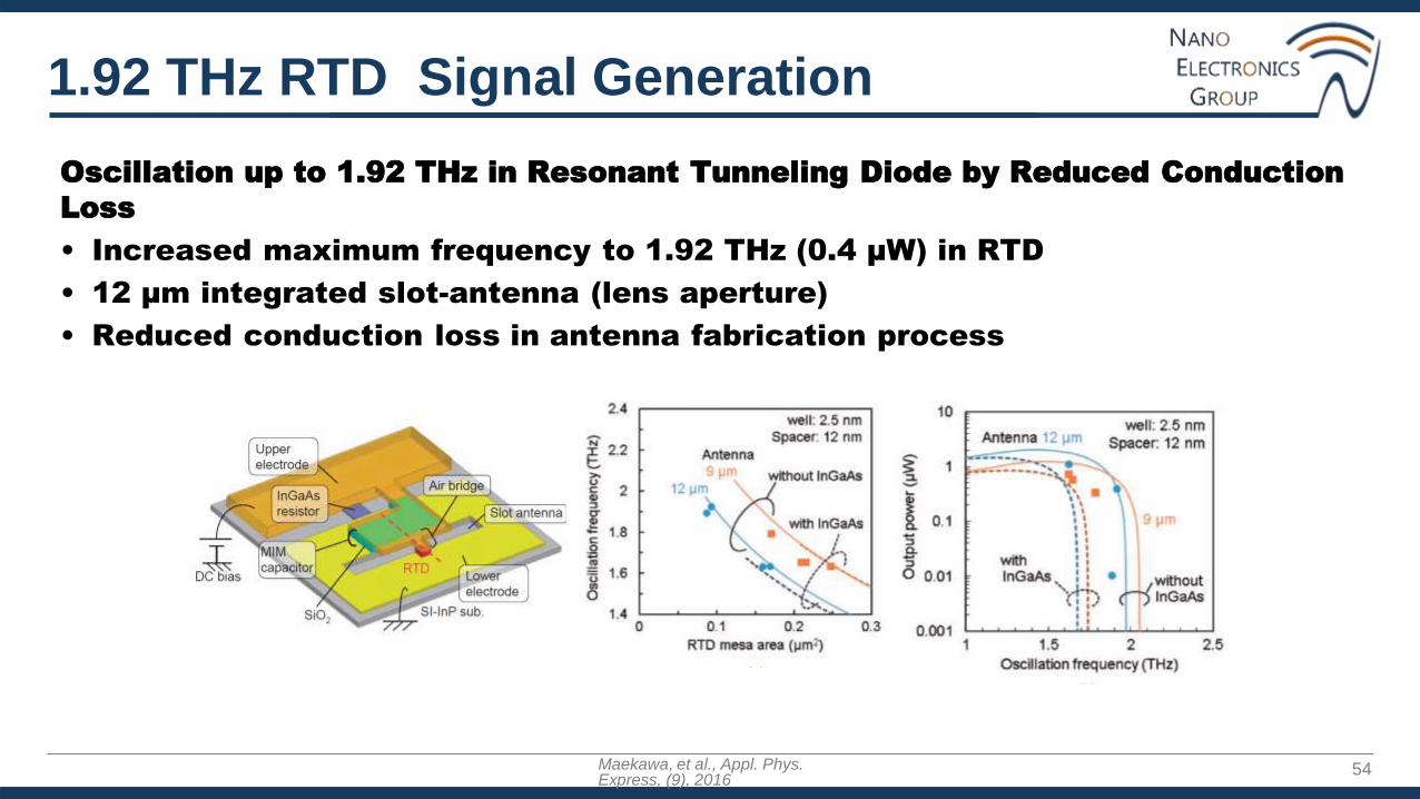
1.92 THz RTD Signal Generation
Oscillation up to 1.92 THz in Resonant Tunneling Diode by Reduced Conduction
Loss
• Increased maximum frequency to 1.92 THz (0.4 µW) in RTD
• 12 µm integrated slot-antenna (lens aperture)
• Reduced conduction loss in antenna fabrication process
Maekawa, et al., Appl. Phys. Express, (9), 2016