PULLM - Connecticut
43
PULLM ATTORNEYS LEE D. HOFFMAN 90 State House Square Hartford, CT 06103-3702 p 860 424 4315 f 860 424 4370 [email protected] December 3, 2010 VIA ELECTRONIC MAIL AND U.S. MAIL Linda Roberts Executive Director Connecticut Siting Council 10 Franklin Sq. New Britain, CT 06051 Re: Kleen Energy Systems, LLC Application for a Certificate of Environmental Compatibility and Public Need for an Electric Generating Facility on River Road, Middletown, Connecticut Docket No. 225D Dear Ms. Roberts: Please find enclosed an original and twenty copies of the Thielsch Engineering report, entitled "Review of Applicable ASME Pressure Piping Code and NFPA Standards and the Evaluation of Their Effect on the Construction or Modification of the Kleen Energy Project Site, Middletown, Connecticut," dated December 3, 2010 submitted by the certificate holder, Kleen Energy Systems, LLC ("Kleen Energy"). This report is filed as a supplement to the pre-filed testimony of Mr. Richard Audette submitted on November 23, 2010. As you will recall, this report was referenced in both Mr. Corvo's and Mr. Audette's pre-filed testimonies and also in Kleen Energy's interrogatory responses dated November 15, 2010. In addition, as you will recall, in accordance with Order 9 of Kleen Energy's revised Decision and Order, Kleen Energy submitted its pipe cleaning procedure on December 1, 2010 as part of the Docket 225C proceeding. Please be advised that Kleen Energy also requests that this procedure be included as an additional exhibit in the Docket 225D hearing scheduled for December 7, 2010. This procedure was also both referenced in both Mr. Corvo's and Mr. Audette's pre-filed testimonies and also in Kleen Energy's interrogatory responses dated November 15, 2010. Copies of the procedure have already been sent to all parties and intervenors of record in Docket 225D. WWW.PULLCOM.COM I BRIDGEPORT I HARTFORD I STAMFORD I WHITE PLAINS
Transcript of PULLM - Connecticut
PULLM ATTORNEYS
LEE D. HOFFMAN
90 State House Square Hartford, CT 06103-3702 p 860 424 4315 f 860 424 4370 [email protected]
December 3, 2010
VIA ELECTRONIC MAIL AND U.S. MAIL
Linda Roberts Executive Director Connecticut Siting Council 10 Franklin Sq. New Britain, CT 06051
Re: Kleen Energy Systems, LLC Application for a Certificate of Environmental Compatibility and Public Need for an Electric Generating Facility on River Road, Middletown, Connecticut Docket No. 225D
Dear Ms. Roberts:
Please find enclosed an original and twenty copies of the Thielsch Engineering report, entitled "Review of Applicable ASME Pressure Piping Code and NFPA Standards and the Evaluation of Their Effect on the Construction or Modification of the Kleen Energy Project Site, Middletown, Connecticut," dated December 3, 2010 submitted by the certificate holder, Kleen Energy Systems, LLC ("Kleen Energy"). This report is filed as a supplement to the pre-filed testimony of Mr. Richard Audette submitted on November 23, 2010. As you will recall, this report was referenced in both Mr. Corvo's and Mr. Audette's pre-filed testimonies and also in Kleen Energy's interrogatory responses dated November 15, 2010.
In addition, as you will recall, in accordance with Order 9 of Kleen Energy's revised Decision and Order, Kleen Energy submitted its pipe cleaning procedure on December 1, 2010 as part of the Docket 225C proceeding. Please be advised that Kleen Energy also requests that this procedure be included as an additional exhibit in the Docket 225D hearing scheduled for December 7, 2010. This procedure was also both referenced in both Mr. Corvo's and Mr. Audette's pre-filed testimonies and also in Kleen Energy's interrogatory responses dated November 15, 2010. Copies of the procedure have already been sent to all parties and intervenors of record in Docket 225D.
WWW.PULLCOM.COM I BRIDGEPORT I HARTFORD I STAMFORD I WHITE PLAINS
PULL ATTORNEYS
Page 2
Should you have any questions concerning the foregoing, please contact me at your convenience.
Respectfully submitted KLEEN ENERGY SYSTEMS, LLC
Lee D. Hoffman Its Attorney
cc: Melanie A. Bachman (via electronic mail) Robert Mercier (via electronic mail) Service List
PULL ATTORNEYS
Page 3
Service List
Alfred E. Smith, Jr. Murtha Cullina LLP Two Whitney Avenue P.O. Box 704 New Haven, CT 06503
Duncan R. Mackay, Esq. Vincent P. Pace, Esq. The Connecticut Light & Power Company P.O. Box 270 Hartford, CT 06141-0270
John R. Morissette Manager-Transmission Siting and Permitting The Connecticut Light & Power Company P.O. Box 270 Hartford, CT 06141-0270
Christopher R. Bernard Manager-Regulatory Policy (Transmission) The Connecticut Light & Power Company P.O. Box 270
-Hartford, CT 06141-0270
Timothy P. Lynch Deputy City Attorney City Attorney's Office City of Middletown 245 deKoven, P.O. Box 1300 Middletown, CT 06457-1300
Earle Roberts 785 Bow Lane Middletown, CT 06457-4810
Jacqueline Talbot Connecticut River Watershed Council, Inc. DeKoven House Community Center 27 Washington Street Middletown, CT 06457

PULL ATTORNEYS
Page 4
Jean M. D'Aquila D'Aquila Law Offices, LLC 100 Riverview Center, Suite 205 Middletown, CT 06457
Susan S. Bransfield, First Selectwoman Town of Portland 33 East Main Street P.O. Box 71 Portland, CT 06480
The Honorable Eileen M. Daily State Senator — 33 rd District 103 Cold Spring Drive Westbrook, CT 06498
The Honorable James A. O'Rourke State Representative — 32 nd District Legislative Office Building, Room 4108 Hartford, CT 06106-1591
ACTIVE/67524.14/CLARSON/2313679v I

THIELSCH ENGINEERING, INC. 195 Frances Avenue
Cranston, Rhode Island 02910-2211 Tel. (401) 467-6454 Fax, (401) 467-2398
December 3, 2010
Mr. Richard E. Audette Project Director Kleen Energy Project O&G Industries, Inc. 1349 River Road Middletown, CT 06457
SUBJECT: Review of Applicable ASME Pressure Piping Code and NFPA Standards and the Evaluation of Their Effect on the Construction or Modification of the Kleen Energy Project Site, Middletown, Connecticut
Dear Mr. Audette:
As you had requested, enclosed is our report covering the "Review of Applicable ASME Pressure Piping Code and NFPA Standards and the Evaluation of Their Effect on the Construction or Modification of the Kleen Energy Project Site, Middletown, Connecticut, and the Attachments that are referenced in the report.
I have all of the Codes and Standards that were included in the review. If additional details are required, please let me know.
Enclosures
/dcbf
cc: Matthew 0. Tobin, O&G w/Encl.
Very truly yours,
TH1ELSCH ENGINEERING, INC. .0misillitiorot,,,
4;\ 0 11- 4-.
z.. - ,..T.ii.o. _
E. *icc Ara D. Nalbandian,
No,17350 Vice President, Enginerirr ((......,,/peNse?...-c.,'".
9/6"tai. 4/11Jorii11100•'\

REVIEW OF APPLICABLE ASME PRESSURE PIPING CODE AND
NFPA STANDARDS AND THE EVALUATION OF THEIR EFFECT ON
THE CONSTRUCTION OR MODIFICATION OF THE
KLEEN ENERGY PROJECT SITE, MIDDLETOWN, CONNECTICUT
Thielsch Engineering was requested by O&G Industries, Inc. ("O&G") to review the
following Codes and Standards and to determine if and how changes and revisions
incorporated into the following Codes and Standards listed below could effect the
construction or modification of the Kleen Energy Project Site in Middletown, Connecticut,
subsequent to the incident that occurred on February 7, 2010:
A. NFPA 37 (2010 Edition);
B. NFPA 54 (2009 Edition);
C. NFPA 54 Temporary Interim Amendment 09-3 (August 25, 2010);
D. NFPA 850 (2010 Edition);
E. NFPA 853 (2010 Edition);
F. ASME B31; and
G. ASME B31.1 Appendix IV and V.
According to the information provided to Thielsch Engineering, the design and construction
of the Kleen Energy Project Site, was based upon the applicable Standards that were in
effect in 2007. Consequently, the review conducted by Thielsch Engineering was
performed to address the relevant changes and revisions included in the above listed
Codes and Standards and to determine if those revisions could effect the reconstruction
or modification of the Project Site subsequent to the incident that occurred on February 7,
2010.
Thielsch Engineering, Inc. 1

The results of Thielsch Engineering's reviews are as follows:
NFPA 37 Standard for Installation and Use of Stationary Combustion Engines and
Gas Turbines
The review of NFPA 37 Standard for the Installation and Use of Stationary Combustion
Engines and Gas Turbines 2006 and 2010 Editions and Tentative Interim Amendment
(TIA-10-1) December 5, 2009, indicated that there were no major changes included in the
2010 Edition that could have effected the construction or modification of the Kleen Energy
Project Site.
NFPA 54 2009 Edition - National Fuel Gas Code
This Code is a safety code that shall apply to the installation of fuel gas piping systems,
appliances, equipment and related accessories. The construction and operation of a
piping system covered by the NFPA 54 (ANSI Z223.1) National Fuel Gas Code is limited
to a maximum operating pressure of 125 psig. This Code shall not apply to fuel gas piping
in electric utility power plants.
The 2006 Edition of this Code, which was in effect in 2007, also stated that NFPA 54 shall
not apply to fuel gas piping in power and atomic energy plants.
It is thus evident that the construction and operating fuel gas piping at pressures higher
than 125 psig installed at Kleen Energy Project Site, is not covered by the requirements
of the NFPA 54 National Code for Fuel Gas Piping.
The review of NFPA 54 2009 Edition (Reference Attachment A) regarding purging of gas
piping, refers to Paragraph "8.3.1 Removal from Service." This paragraph states the
following: "When gas piping is to be opened for an addition, a modification of service, the
section to be worked on shall be turned off from the gas supply at the nearest convenient
point and the line pressure vented to the outdoors or to ventilated areas of sufficient size
to prevent an accumulation of flammable mixtures. The remaining gas in this section of
Thielsch Engineering, Inc. 2

pipe shall be displaced with an inert gas."
However, when piping full of air is placed in operation, the air in the piping shall be
displaced with fuel gas, except where such piping is to be purged with inert gas prior to the
induction of fuel gas, as required by Table 8.3.2 (Reference Attachment A).
The review of NFPA 54 Temporary Interim Amendment TIA-09-3 (Reference Attachment
B) indicated that the purging of piping, as described in Paragraph 8.3 of NFPA 54 2009
Edition, is revised and the revised requirements shall be in accordance with Paragraphs
8.3.1 through 8.3.3 (TIA-09-3).
Paragraph 8.3.1 covers Piping Systems required to be purged outdoors and 8.3.3 covers
"Purging Appliances and Equipment." Even though purging requirements of piping for
"Removal from Service" or "Placing in Operation" are relatively similar to Paragraph 8.3 of
NFPA 54 2009 Edition, additional requirements, that are detailed in Paragraphs 8.3.1.3,
8.3.1.4, 8.3.2, 8.3.2.1 and 8.3.2.2, cover piping systems allowed to be purged indoors and
outdoors, purging procedures and combustible gas detectors.
Paragraph 8.3.1 also describes the characteristics of gas piping systems that are required
to be purged only to the outdoors. The criteria were selected to distinguish between the
piping systems located in industrial, large commercial and large multi-family buildings from
those located in light commercial and smaller residential buildings. The gas piping systems
installed in industrial, large commercial and large multi-family buildings are considered to
be larger, more complex systems for the purposes of defining these purging requirements.
Because of their layer pipe volumes or potential for higher flow rates, these systems
require procedures to ensure that large volumes of fuel gases are not released indoors and
that flammable mixtures do not occur within the piping itself.
Based upon the above discussions, it is apparent that NFPA 54 2009 National Fuel Gas
Code (2009 Edition) and NFPA 54 Temporary Interim Amendment TIA-09-3 (August 25,
Thielsch Engineering, Inc. 3

2010) would not effect the construction or modification of the Kleen Energy Project Site.
In fact, NFPA 54 specifically excludes piping in electrical utility power plants that supply gas
utilized directly as the fuel in the generation of electricity. These systems typically operate
at pressures greater than 125 psig (861.8 kPa) which is beyond the scope of NFPA 54.
NFPA 850 - Recommended Practice for Fire Protection of Electrical Generating
Plants and High Voltage Direct Current Converter Stations - 2010 Edition
The review of NFPA 850 - 2010 Edition, indicated that new chapters on wind turbine
generating facilities, solar thermal power generation, geothermal power plants and
integrated gasification combined cycle (IGCC) generating facilities (Chapters 10-13) have
been added. The 2010 Edition also includes recommendations for the fire protection
design process and fire protection design basis documentation. Moreover, the use of
compressed air foam systems and fast depressurization systems have been reorganized
and recommendations for the use of these systems are included.
The review of the Tentative Interim Amendment (TIA-10-1) August 25, 2010, indicated that
Paragraph 11.4.1.1 (Chapter 11 - Solar Thermal Power Generation) has been revised.
The revised paragraph, provided in Attachment C, indicated that "ANSI/ASME B 31.1
Power Piping Code should be followed in the design of the HTF piping system."
The review of Chapter 8 "which identifies fires and explosion hazards of Combustion
Turbines and Internal Combustion Engines and specifies recommended protection criteria,"
indicated that the installation and operation of combustion turbine internal combustion
engine generators should be in accordance with Chapter 11 and NFPA 37 Standard for the
Installation and Use of Stationary Combustion Engines and Gas Turbines. The
recommended practices in NFPA 850 (8.5.1.2) also states that "Site specific design
considerations or manufacturer's typical design will govern what equipment has enclosures
Thielsch Engineering, Inc. 4
or how many separate enclosures will be provided for the combustion turbine." It is further
stated in Paragraph 8.5.3.5 that "In order to prevent conditions that could cause a fire while
the unit is operating, control packages should include the parameter monitoring and
shutdown capabilities described in Chapter 7 of NFPA 37, Standard for the Installation and
Use of Stationary Combustion Engines and Gas Turbines."
Additionally, the review of Tentative Interim Amendment TIA-10-2, November 9, 2010,
provided in Attachment D revealed that Paragraph 7.2 "Fuel Handling - Gas" has been
revised and new paragraphs and subparagraphs covering cleaning fuel gas piping, inerting
prior to the introduction of fuel gas to the fuel gas piping, gas purging and maintenance and
repair of fuel gas piping have been added (see Paragraphs 7.2.4 through 7.2.7.2).
Even though the review of the NFPA 850 2010 Edition would not effect construction or
modification of the Project Site at Kleen Energy Project Site, the recommended practices
detailed in Tentative Interim Amendment TIA-10-2, November 9, 2010, may effect the
cleaning, inerting, purging and/or introduction of fuel gas to the fuel gas piping system.
In view of the above, the Fuel Gas System Pipe Cleaning Procedure which has been
prepared by O&G / Kleen Energy addresses the requirements detailed in TIA-10-2. Its
implementation should satisfy the NFPA 850 2010 Edition and TIA-10-2, November 9,
2010.
ASME B 31 Code for Pressure Piping
The ASME B31 Code for Pressure Piping has various sections that address the designs
of specific piping systems utilized in various industries and commercial applications. The
document provided in Attachment E lists the sections of B31 Pressure Piping Code and
provides areas of specific application. Except for ASME B 31.1 Power Piping Code, the
remaining Codes may not effect the construction or modification of the Kleen Energy
Project Site.
Thielsch Engineering, Inc, 5

ASME B31.1 Code for Power Piping (Appendices IV and V)
According to the information provided to Thielsch Engineering, the design and construction
of the piping systems for the electric power generating station were performed in
accordance with the requirements of ASME B31.1 Code for Power Piping - 2007 Edition.
This code prescribes the requirements for the design materials, fabrication, erection test,
inspection, operation and maintenance of piping systems.
This Code covers boilers and high temperature, high pressure water boilers, in which:
steam or vapor is generated at a pressure more than 15 psig [100 kPa (gage)]; and, high
temperature water is generated at pressures exceeding 160 psig [1103 kPa (gage)];
and/or, temperatures exceeding 250°F (120°C). According to the B 31.3 Code, boiler
external piping shall be considered as the piping which begins where the boiler proper
terminates (Le., at the first circumferential joint for welding and connections); or the face
of the first flange is bolted flanged connections; or the first threaded joint in that type of
connection; and, which extends up to and including the valve or values required by this
code. The terminal points themselves are considered part of the boiler external piping.
It should also be mentioned that the B 31.1 Code does not apply to the following:
a. Economizers, heaters, pressure vessels and components covered by
sections of the ASME Boiler and Pressure Vessel Code;
b. Building heating and distribution steam and condensate piping designed for
15 psig [100 kPa (gage] or less, or hot water heating systems designed for
30 psig [200 kPa (gage)] or less;
c. Piping for hydraulic or pneumatic tools and their components downstream of
the first block or stop valve off the system distribution header; and
d. Towers, building frames, tanks, mechanical equipment, instruments and
foundations.
It should also be mentioned that since the 2010 Edition of the B 31.1 Power Piping Code
Thielsch Engineering, Inc. 6

has not been issued to date, the 2007 Edition with the 2008 and 2009 Addenda would be
considered as the Code that would have been applicable during the reconstruction of the
Kleen Energy Project Site.
Thielsch Engineering reviewed all of summary of changes detailed in the ASME B 31.1a -
2008 and ASME B 31.1b - 2009, provided in Attachment F.
Most of the changes and/or revisions to this Code were related deletions and/or inclusion
of materials (allowable stresses, reclassification by P. Numbers) referenced Standards and
specifications (Le., ASCE/SEI7, ANSI, API, ASME, ASTM, MSS, AWS, NFPA, etc.) and
provided clarification to the guidelines for fabrication, assembly and erection of piping
systems.
Based upon the review of these Addenda, it is concluded that since the 2010 Edition of the
B 31.1 Power Piping Code has not been published to date, the requirements included in
the B 31.1 Power Piping Code 2007 Edition and B 31.1a - 2008 and B 31.1b - 2009
Addenda would not effect the reconstruction or modification of the Kleen Energy Project
Site.
Regarding the review of Appendices IV and V that were identified as potential areas of
interest, it should be noted that both Appendices IV and V are nonmandatory. Appendix
IV covers "Corrosion Control for ASME B 31.1 Power Piping Systems" and Appendix V
covers "Recommended Practice for Operation, Maintenance and Modification of Power
Piping Systems." Both of these nonmandatory Appendices contain guidelines that are
applicable to existing operating piping contained in the scope of ASME B 31.1, as well as
"new construction."
It should be recognized that during the reconstruction of the electric power generating
Project Site in Middletown, CT, many sound corrosion control programs were instituted and
inspection of piping and components for external and internal corrosion were performed
Thielsch Engineering, Inc. 7

by O&G to ensure the acceptability of the piping systems for compliance with the
requirements of the applicable Codes and Standards, including ASME B 31.1 Code for
Power Piping. In addition to the inspections performed, repair and replacement
considerations were incorporated to further ensure the structural integrity and performance
reliability of the power piping systems, including the vessels and components.
The review of Appendix IV indicated that the minimum requirements for corrosion control
of power piping systems, outlined in Appendix IV, were adequately met during the
construction or modification of the Project Site.
Regarding the practices recommended in Appendix V, it should be noted that the B 31.1
Power Piping Code prescribes minimum requirements for the construction of power and
auxiliary service piping within the scope of the B 31.1 Code. The Code; however, does not
provide rules or other requirements for a determination of optimum system function,
effective plan operations, or other measures necessary to assure the useful life of the
piping system. These concerns are the responsibility of the designer and after construction
turnover, the Operating Company personnel responsible for plant activities.
Since the purpose of nonmandatory Appendix V is intended for achieving both reliable
service and a predictable life in the operation of power piping systems, the implementation
of the recommended practices would be applicable to potential modification and not to the
operation and/or maintenance of the piping systems because the piping systems are
considered to be "new construction or reconstruction."
In view of the above, it should be recognized that during the reconstruction of the damaged
piping systems, several inspection programs were prescribed and implemented for
analyzing piping system distortions or potential failures. These programs were intended
to identify distortions or failures and assure compatibility between the materials and
components of existing piping systems with those portions undergoing repair, replacement
or modifications.
Thielsch Engineering, Inc, 8

14,or V`L'uti,o, % 0
= I 411
Ara D. Nalbandian, P.E tt 1.40.1.1ce,v350„42#9
Ak98/0141k0:0" Vice President, Engineering
It should be noted that during the reconstruction of the electric power generating Project
Site, the piping systems, including the high energy piping, were thoroughly inspected and
subjected to nondestructive examinations to ensure that the general condition of the
supports, hangers, guideS, anchors and attachments, etc., were in the proper positions in
conformance with the piping design. It should also be noted that the inspection programs
and procedures were carried out by or under the direction of persons qualified by training
or experience in the inspection and construction of the power plants piping and equipment
designed in accordance with the applicable Codes and Standards, including ASME B 31.1
Power Piping Code,
THIELSCH ENGINEERING, INC.
Thielsch Engineering, inc. 9

ATTACHMENT A
NFPA 54 NATIONAL FUEL GAS CODE - 2009 EDITION
•8.3 PURGING

NFPA and National Fire Protection Association are registered trademarks of the National Fire Protection Association, Quincy, Massachusetts 02169.
Copyright NFPA

8.3* Purging.
8.3.1 Removal from Service. When gas piping is to be opened for an addition, a modification, or service, the section to be worked on shall be turned off from the gas supply at the nearest convenient point and the line pressure vented to the outdoors or to ventilated areas of sufficient size to prevent accumulation of flammable mixtures. The remaining gas in this section of pipe shall be displaced with an inert gas as required by Table 8.3.1.
Table 8.3.1 Length of Piping Requiring Purging with Inert Gas for Servicing or
Modification
Nominal Length of Piping Pipe Size Requiring Purging
(in.) (ft) 2V2 > 50
3 > 30 4 > 15 6 > 10
8 or larger Any length For SI units, 1 ft 0.305 m.
8.3.2 Placing in Operation. When piping full of air is placed in operation, the air in the piping shall be displaced with fuel gas, except where such piping is required by Table 8.3.2 to be purged with an inert gas prior to introduction of fuel gas. The air can be safely displaced with fuel gas, provided that a moderately rapid and continuous flow of fuel gas is introduced at one end of the line and air is vented out at the other end. The fuel gas flow shall be continued without interruption until the vented gas is free of air. The point of discharge shall not be left unattended during purging. After purging, the vent shall then be closed. Where required by Table 8.3.2, the air in the piping shall first be displaced with an inert gas, and the inert gas shall then be displaced with fuel gas.
Table 8.3.2 Length of Piping Requiring Purging with Inert Gas Before Being
Placed in Operation
Nominal Length of Piping Pipe Size Requiring Purging
(in.) (ft) 3 > 30 4 > 15 6 > 10
8 or larger Any length
Copyright NFPA
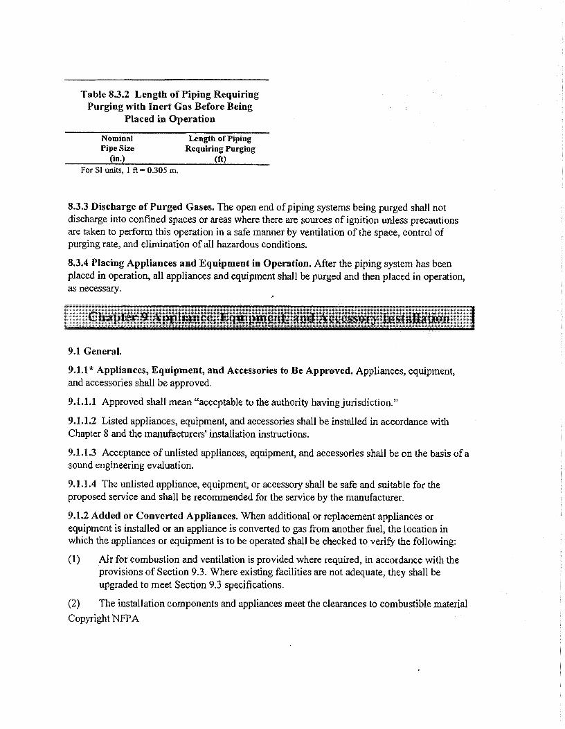
Table 83.2 Length of Piping Requiring Purging with Inert Gas Before Being
Placed in Operation
Nominal Length of Piping Pipe Size Requiring Purging
(in.) (ft) For SI units, 1 ft = 0305 m.
8.3.3 Discharge of Purged Gases. The open end of piping systems being purged shall not discharge into confined spaces or areas where there are sources of ignition unless precautions are taken to perform this operation in a safe manner by ventilation of the space, control of purging rate, and elimination of all hazardous conditions.
8.3.4 Placing Appliances and Equipment in Operation. After the piping system has been placed in operation, all appliances and equipment shall be purged and then placed in operation, as necessary.
9.1 General.
9.1.1* Appliances, Equipment, and Accessories to Be Approved. Appliances, equipment, and accessories shall be approved.
9.1.1.1 Approved shall mean "acceptable to the authority having jurisdiction."
9.1.1.2 Listed appliances, equipment, and accessories shall be installed in accordance with Chapter 8 and the manufacturers' installation instructions.
9.1.1.3 Acceptance of unlisted appliances, equipment, and accessories shall be on the basis of a sound engineering evaluation.
9.1.1.4 The unlisted appliance, equipment, or accessory shall be safe and suitable for the proposed service and shall be recommended for the service by the manufacturer.
9.1.2 Added or Converted Appliances. When additional or replacement appliances or equipment is installed or an appliance is converted to gas from another fuel, the location in which the appliances or equipment is to be operated shall be checked to verify the following:
(1) Air for combustion and ventilation is provided where required, in accordance with the provisions of Section 9.3. Where existing facilities are not adequate, they shall be upgraded to meet Section 9.3 specifications.
(2) The installation components and appliances meet the clearances to combustible material Copyright NFPA
ATTACHMENT B
NFPA 54 NATIONAL FUEL GAS CODE
•T1A-09-3, AUGUST 25, 2010

Li IMF PA:
Tentative Interim Amendment
NFPA 54 National Fuel Gas Code
2009 Edition Reference: 8.3 TIA 09-3 (SC 10-8-22/714 Log 1984R)
Pursuant to Section 5 of the NFPA Regulations Governing Committee Projects, the National Fire Protection Association has issued the following Tentative Interim Amendment to NFPA 54. Notional Fuel Gas Code, 2009 edition. The TIA was processed by the Teclmical Committee on National Fuel Gas Code, and was issued by the Standards Council on August 5, 2010, with an effective dale of August 25, 2010.
A Tentative Interim Amendment is tentative because it has not been processed through the entire standards-making procedures. It is interim because it is ellective only between editions of the standard. A T1A automatically becomes a proposal of the proponent for the next edition of the standard; as such, it then is subject to all of the procedures of the standards-making process.
I. Revise Section 8.3 to read:
8.3* Purging Requirements. The purging of piping shall be in accordance with 8.3.1 through 8.3.3.
8.3.1* Piping Systems Required to be Purged Outdoors. The purging of piping systems shall he in accordance with the provisions of 8.3.1.1 through 8.3.1.4 where the piping system meets either of the following: I. The design operating gas pressure is greater than 2 psig (14 kPa). 2. The piping being purged contains one or more sections of pipe or tubing greater than 2 in. and exceeding the lengths in Table 8.3.1.1.
8.3.1.1 Removal from Service. Where existing gas piping is opened, the section that is opened shall be isolated from the gas supply and the line pressure vented in accordance with 8.3,13. Where gas piping meeting the criteria of Table 8.3.1,1 is removed from service, the residual fuel gas in the piping shall be displaced with an inert gas.
Table 8.3.1.1 Size and Len th of Pi iing Nominal Pipe Length of Size (in.)
Piping (ft) 2 'A > 50 3 > 30 4 > 15 6 10 8 or larger Any length
For SI units: 1 ft =304.8 mm.
83.1.2* Placing in Operation. Where gas piping containing air and meeting the criteria of Table 8.3.1.1 is placed in operation, the air in the piping shall first be displaced with an inert gas. The inert gas shall then he displaced with fuel gas in accordance with 8.3.1.3,
8.3.1.3 Outdoor Discharge of Purged Gases. The open end of a piping system being pressure vented or purged shall discharge directly to an outdoor location, Purging operations shall comply with all of the following requirements: 1. The point of discharge shall be controlled with a shutoff valve. 2. The point of discharge shall be located at least 10 11 (3 m) front sources of ignition, at least 10 0 (3 m) from building openings and at least 25 II
(7.6 in) from mechanical air intake openings. 3. During discharge, the open point of discharge shall be continuously attended and monitored with a combustible gas indicator that complies with
8,3.1.4, 4, Purging operations introducing fuel gas shall be stopped when 90% fuel gas by volume is detected within the pipe. 5. Persons not involved in the purging operations shall be evacuated from all arvas within 10 II (3 m) of the point of discharge.
8.3.1.4* Combustible Gas Indicator. The combustible gas indicator used during purging operations shall be listed and shall be calibrated in accordance with the manufacturer's instructions and recommended schedule. The combustible gas indicator uscd for pipe discharge monitoring shall numerically display a volume scale front 0% to 100% with a resolution of not greater than 1% increments.

II NFPAC
Tentative Interim Amendment
NFPA 54 National Fuel Gas Code
2009 Edition Reference: 8.3 TIA 09-3 (SC I0-8-22/TIA Log it984R,)
Pursuant to Section 5 of the NFPA Regulations Governing Committee Projects, the National Fire Protection Association has issued the following Tentative Interim Amendment to NFPA 54. National Fuel Gas Code, 2009 edition. The TR was processed by the Technical Committee on National Fuel Gas Code, and was issued by the Standards Council on August 5, 2010, with an effective date of August 25, 2010.
A Tentative Interim Amendment is tentative because it has not been processed through the entire standards-making procedums. It is interim because it is effective only between editions of the standard, A T1A automatically becomes a proposal of the proponent for the next edition of the standard; as such, it then is subject to all of the procedures of the standards-making process.
I. Revise Section 8,3 to read:
8.3* Purging Requirements. The purging of piping shall be in accordance with 8.3.1 through 8.3.3.
8.3.1" Piping Systems Required to be Purged Outdoors. The purging of piping systems shall be in accordance with the provisions of 8.3.1.1 through 8.3.1.4 where ihe piping system meets either of the following: I. The design operating gas pressure is greater than 2 psig (14 kPa). 2. The piping being purged contains one or more sections of pipe or tubing gmater than 2 in, and exceeding the lengths in Table 8.3.1.1.
8.3.1.1 Removal from Service. Where existing gas piping is opened, the section that is opened shall be isolated from the gas supply and the line pressure vented in accordance with 8.3,13. Where gas piping meeting the criteria of Table 8.3.1.1 is removed from service, the residual fuel gas in the piping shall be displaced with an inert gas.
Table 8.3.1.1 Size and Length of Piping_ Nominal Pipe Length of Si-12 (in.) Piping (ft) 2 'A > 50 3 > 30 4 > 6 10 8 or larger Any length
For SI units: 1 ft =304.8 min.
83.1.2* Placing in Operation. Where gas piping containing air and meeting the criteria of Table 8.3.1.1 is placed in operation, the air in the piping shall first be displaced with an inert gas The inert gas shall then he displaced with fuel gas in accordance with 8.3.1.3.
8.3.1.3 Outdoor Discharge of Purged Gases. The open end of a piping system being pressure vented or purged shall discharge directly to an outdoor location. Purging operations shall comply with all of the following requirements: I. The point of discharge shall be controlled with a shutoff valve, 2. The point of discharge shall be located at least 10 ft (3 m) from sources of ignition, at least 10 II (3 rn) from building openings and at least 25 ft
(7.6 in) from mechanical air intake openings. 3. During discharge, the open point of discharge shall be continuously attended and monitored with a combustible gas indicator that complies with
83.1 4. 4. Purging operations introducing fuel gas shall be stopped when 90% fuel gas by volume is detected within the pipe. 5. Persons not involved in the purging operations shall be evacuated from all arms within 10 ft (3 m) of the point of diseharge.
8.3.1.4* Combustible Gas Indicator. The combustible gas indicator used during purging operations shall be listed and shall be calibrated in accordance with the manufacturer's instructions and recommended schedule. The combustible gas indicator used for pipe discharge monitoring shall numerically display a volume scale from 0% to 100% with a resolution of not greater than 1% increments.

8.3.2* Piping Systems Allowed to Be Purged Indoors or Outdoors. The purging of piping systems shall be in accordance with the provisions of 8.3.2.1 where the piping system meets both of the following: I. The design operating pressure is 2 psig (14 kPa) or less. 2. The piping system being purged is constructed entirely from pipe or tubing of 2-in. nominal size or smaller, or larger pipe or tubing with lengths
shorter than specified in Table 8,3.1.1.
83.2.1* Purging Procedure. 'fhe piping system shall be purged in accordance with one or more of the following: I. The piping shall be purged with fuel gas and shall discharge to the outdoors. 2. The piping shall be purged with fuel gas and shall discharge to the indoors or outdoors through an appliance burner not located in a combustion
chamber. Such burner shall be provided with a continuous source of ignition. 3. The piping shall be purged with fuel gas and shall discharge to the indoors or outdoors through a burner that has a continuous source of ignition
and that is designed for such purpose. 4. The piping shall be purged with fuel gas that is discharged to the indoors or outdoors, and the point of discharge shall be monitored with a listed
combustible gas detector in accordance with 8.3.2.2. Purging shall be stopped when fuel gas is detected. 5. The piping shall be purged by the gas supplier in accordance with written procedures,
8.3.2.2 Combustible Gas Detector. The combustible gas detector used during purging operations shall be listed and shall be calibrated or tested in accordance with the manufacturer's instructions and recommended schedule. The combustible gas detector used for pipe discharge monitoring shall indicate the presence of fuel gas,
8.3.3 Purging Appliances and Equipment. After the piping system has been placed in operation, appliances and equipment shall be purged before being placed into operation,
2. Revise 4.8.3 w read
A.83 The process of purging gas piping of filet gas or charging gas piping that is full of air with fuel gas must be performed in a manner that will minimize the potential for a flammable mixture to be developed within the piping. Also, a significant amount of flammable gas should not be released within a confined spam. Natural gas and propane suppliers add a distinctive odor to their gas to aid in its detection. However, when a new system is brought into service and unodorized gas is detected, the company supplying the gas should be contacted to iuform it of the situation and to determine what action should be taken.
A.83.1 Paragraph 8.3,1 describes the characteristics of gas piping systems that are required to be purged only to the outdoors. The criteria were selected to distinguish between piping systems located in industrial, large commercial, and large multifamily buildings from those located in light commercial and smaller residential buildings. The gas piping systems installed in industrial, large commercial, and large multifamily buildings are considered to be larger more complex systems for the purposes of defining their purging requirements. Because of their larger pipe volumes or potential for higher flow rates, these systems require procedures to ensure that large volumes of fuel gases are not released indoors and that flammable mixtures do not occur within the piping itself Installers of these complex systems deal with considerably more variables that may result in a higher potential for discharge of large gas volumes during purging operations. Specific occupancy categories such as industrial, manufacturing, commercial, and large multifamily were not included in the fuel gas code. U.S. building codes define these occupancies for the purpose of construction and safety requirements. There is no general relation between the occupancy types, as defined by the building codes, and the size of gas piping system to be installed in that occupancy. The gas piping size and operating pressure are based on the nature of the piping system and gas appliances to be installed and are not dependent upon a building's occupancy type or classification.
.4.8.3.1.2 It is recommended that the oxygen levels in the piping he monitored during the purging process to determine when sufficient inert gas has been introduced. The manufacturer's instructions for monitoring instruments must be followed when performing purge operations.
A.8.3.1.4 Combustible gas indicators are available with different scales. For purging, it is necessary to use the percent gas in air scale and to follow Me manufacturer's operating instructions. The % LEL scale should not be used as it is not relevant to purging.
A.83.2 The criteria were selected to describe typical gas piping systems located in light commercial and the smaller residential family buildings. Gas piping systems installed in these buildings are considered to be smaller and less complex systems for the purposes of defining their purging requiremenLs. Installers have familiarity with purging these systems and the potential for discharge of large gas volumes during purging operations is tow. Also see A.8.3.1.
A.8..3.2.1 Where small piping systems contain air and are purged to either the indoors or outdoors with fuel gas, a rapid and uninterrupted flow of fuel gas must be introdumd into one end of the piping system and vented out of the other end so as to prevent the development of a combustible fuel/air mixture. Purging these systems can be done either using a source of ignition to ignite the fuel gas or by using a listed combustible gas indicator that can detect the presence of fuel gas.
Issue Date: August 5, 2010
Effective Date: August 25, 2010
(Note: For further information on NFPA Codes and Standards, please see %my, nipa dendelist)
Copyright co 2010 All Rights Reserved NATIONAL FIRE PROTECTION ASSOCIATION
ATTACHMENT C
NFPA 850 - RECOMMENDED PRACTICE FOR FIRE PROTECTION FOR ELECTRIC GENERATING PLANTS AND
HIGH VOLTAGE DIRECT CURRENT CONVERTER STATIONS - 2010 EDITION
•TIA 10-1, AUGUST 10, 2010

Lij NFPA
Tentative Interim Amendment
NFPA 850 Recommended Practice for Fire Protection for Electric Generating Plants and High
Voltage Direct Current Converter Stations 2010 Edition
Reference: 11.4 1.1 TIA 10-1 (sc 10-8-28/TIA Log 11982)
Pursuant to Section 5 of the NITA Regulations Governing Committee Projects, the National Fire Protection Association has issued the Ibllowing
Tentative Interim Amendtnem to NFPA 850, Recommended Practice for Fire Protection for Electric Generating Plants aml High Voltage Direct ('urrent Converter Stations. 201() edition. The TIA was processed by the Technical Committee on Electric Generating Plants, and was issued by the Standards Council on August 5, 2010, with an effective date of August 25, 2010.
A Tentative interim Amendment is tentative because it has not been processed through thc entire standards-making procedures. It is interim because it is etTective only between editions of the standard. A TIA automatically becomes a proposal of the proponent for the next edition of the standard: as such, it then is subject to all of the procedures of the standards-making process.
I, Revise 11.4 I. 1 to read as follows
11.4.1.1* ANSI/ASME B31.I, Power Piping, should be followed in the design of I-ITF piping systems. Piping and finings should be properly designed to resist an exposure fire until protection can bc achieved by water spray. Careful consideration should be given to the design, application. cmstruction, and installation of connections (e.g., rotating ball joint, flexible hose, etc.) employed in areas such as the FITE loop connections of adjacent solar collector assemblies so as to prevent possible sources of 1-ITF leaks. Gaskets and seals should be compatible with HIF. Flanges and piping Connections on HTF systems should have guards.
Issue Date: August 5, 2010
Effective Date: August 25, 2010
(Note: For further information on NFPA Codes and Standards, please see wwwM)a tnkodetm)
Copyright 2010 All Rights Reserved NATIONAL EIRE PROTECTION ASSOCIAI ION
ATTACHMENT 0
NFPA 850 - RECOMMENDED PRACTICE FOR FIRE PROTECTION FOR ELECTRIC GENERATING PLANTS AND
HIGH VOLTAGE DIRECT CURRENT CONVERTER STATIONS - 2010 EDITION
•TIA 10-2, NOVEMBER 9, 2010

ci NFPA
Tentative Interim Amendment
NFPA 850 Recommended Practice for Fire Protection for Electric Generating Plants and High
Voltage Direct Current Converter Stations
2010 Edition
Reference: 3.3.26, 3.3.27. and 7.2 TM 10-2 (SC 10-10-8/TLA Log #1004)
Pursuant to Section 5 of the NFPA Regulations Governing Committee Projects, the National Fire Protection Association has issued the following Tentative Interim Amendment to NFPA 850, Recommended Practice for Fire Protection JOr Electric Generating Plants and High Voltage Direct Current Converter Stations, 2010 edition. The TR was processed by the Technical Committee on Electric Generating Plants, and was issued by the Standards Council on October 20, 2010, with an effective date of November 9, 2010.
A Tentative Interim Amendment is tentative because it has not been processed through the entire standards-making procedures. It is interim because it is effective only between editions of the standard. A T1A automatically becomes a proposal of the proponent for the next edition of the standard; as such, it then is subject to all of the procedures of the standards-makine process,
I. Add new definitions as follows;
3.3.26 Gas Purging. The act of replacing air in a fuel gas pipeline with gas by direct replacement so rapidly that a minimum of mixing between the two gases occurs.
3.3.27 Gas Blowing. The act of cleaning a fuel gas pipeline using high pressure/velocity fuel gas.
2 Revise 7..2 to read as follows:
7.2 Fuel Handling— Gas.
7.2.1* General. The storage and associated piping systems for gases in the gaseous or liquefied states should comply with
ASME B3I.1, Power Piping; NFPA 54, National Fuel Gas Code; NFPA 55, Compressed Gases and Cryogenic Fluids
Code; and NFPA 58, Liquefied Petroleum Gas Code. For pressures exceeding the scope of the aforementioned
documents, refer to ASME 831.8-2010, Gas Transmission and Distribution Piping Systems.
A.7.2.1 NEPA 54, National Fuel Gas Code, provides guidance for the design, installation, and testing of applications operating at pressures less than 125 psig (861,8 kPa), such as hot water heaters, space heaters, cooking applications, auxiliary boilers and emergency generators, and should be considered a good reference for these type applications in power generating facilities. NFPA 54 specifically excludes piping in electric utility power plants that supplies gas utilized directly as the fuel in the aeneration of electricity. These systems typically operate at pressures greater than 125 psig
(861 -.8 kPa) which is beyond the scope of NFPA 54.
7.2.2 Shutoff Valve. The plant's main and igniter natural gas shutoff valve should be located near an exterior wall. The valve should be provided with both manual and automatic closing capabilities locally, and remote closing capability from the control room. The valve should be arranged to fail closed on the loss of power or pneumatic control.

7.2.3 Electrical Equipment. Electrical equipment in areas with potentially hazardous atmospheres should be designed
and installed in compliance with Articles 500 and 501 of NFPA 70, National Electrical Code, and ANSI C2, National
Electrical Safety Code.
7.2.4 Cleaning. The following cleaning methods should be considered when designing, installing, and testing the fuel gas
piping systems:
(1)* Pigging (2)* Aerated water jets (3)* I Ugh-pressure water jets (4)* Nonflammable gaseous media
A.7.2.4(1) Pigging is discussed at length in CGA G-5.6 Section 6, which describes mechanical scraping or pigging.
A.7.2.4(2) Aerated water jet flushing is a process where highly aerated water is forced as a slug down a pipe at speeds of 40 to 80 feet per second (12,2 to 24.4 meters per second) to dislodge debris, weld slag, corrosion deposits. and other foreign objects from the pipe.
A.7.2.4(3) High-pressure water jet flushing is a process where high-pressure jets are used to scour debris, weld slag. corrosion deposits, and other foreign objects from the pipe.
A.7.2.4(4) Nonflammable gaseous media methods for clearing debris from [he fuel gas piping include the use of air, an inert gas (such as nitrogen). or steam. These methods employ the same principle as a gas blow, with thc nonflammable medium substituted for the natural gas. The key to making any of these methods work is to achieve sufficient flow velocity within the piping system to blow any debris that can damage the equipment in operation out of the piping. Guidance regarding recommended flow rates should be provided by the equipment manufacturer.
7.2.4.1 The hazards associated with each type of cleaning media should be considered,
7.2.4.2 Gas blowing for cleaning pipe is inherently dangerous and should be avoided.
7.2.4.3 If gas blowing for cleaning pipe cannot be avoided, a flare stack should be provided for the discharge.
7.2.4.4 If a flare stack is not provided, the precautions listed in 7.2.4.4.1 through 7.2.4.4.12 should be taken.
7.2.4.4.1 Personnel responsible for directing a gas blow operation should be knowledgeable in all aspects of the operation.
7.2.4.4.2 Site specific procedures should be developed that address all aspects of the gas blow operation.
7.2.4.4.2.1 Site specific procedures should take into account guidance and parameters regarding recommended flow rates
provided by the equipment manufacturer.
7.2.4.4.3 Site specific gas dispersion analyses should be conducted,
7.2.4.4.4 Potential ignition sources should be eliminated from the area.
7.2.4.4.5 Piping and associated equipment should be grounded.
7.2.4.4.6 Gas detection equipment should be placed in appropriate areas to ensure adequate gas dispersion occurs and to
identify gas migration into areas where personnel or property may be at risk.
7.2.4.4.7 On-site personnel should be reduced to only those necessary to support the gas blow operation (e.g., off hours or
weekend).
7.2.4.4.8 All on-site personnel should be knowledgeable of the safety protocols associated with gas blow operation.

7.2.4.4.9 Communication protocol should be established for warning personnel on site in the event of an incident,
including the appropriate actions to take.
7.2.4.4.10 Discharge vent(s) should be directed upward to safe outdoor area(s) above all equipment and away from all
building air intakes.
7.2.4.4.1 1 Public officials should be notified where interruptions to normal flow of traffic or calls from the public can be anticipated,
7.2.4.4.12 The public in the vicinity of the gas discharge should be notified if it is anticipated the public will be affected by the noise or odor.
7.2.5* Inerting. Prior to the introduction of fuel gas to the fuel gas piping, inerting should be performed,
A.7.2.5 It is often recommended that oxidants like air be diluted by a nonreactive ("inert") gas, such as nitrogen, carbon dioxide, or argon, to levels such that when a flammable gas is introduced a flammable mixture is not generated. The reverse is also true; dilute the fuel before adding air. Flammability ranges for various fuels are noted as part orlable 4,4.2 of NFPA 497. While this addresses fire hazards, the nonreactive gas is an asphyxiant and proper cautions are to be followed, This best practice is discussed in CGA G-5.6 Section 8.11.3,
7.2.6 Gas Purging. Gas purging, whether indoor or outdoor, should be attended, monitored with a combustible gas indicator, and stopped when fuel gas purity indicates completion (e.g. 95% fuel gas).
7.2.6.1 Gas purging at pressures below 125 psig (861.8 kPa) should be performed in accordance with the applicable
sections of NFPA 54.
7.2.6.2 Gas purging at pressures exceeding 125 psii!, (861.8 kPa) should be performed in accordance with 7.2,4,2 or
7.2.4.3.
7.2.7* Maintenance and Repair. The hazards associated with flammable gases and asphyxiants should be considered
when performing maintenance and repairs.
A.7.2.7 Maintenance and repair of fuel gas piping should be performed in accordance with Subsection 9.8.2 of CGA 0- 5,6.
7.2.7.1 Fuel gas piping should be inerted in accordance with 7.2.5 prior to maintenance and repair.
7.2.7.2 When fuel gas piping is being inerted with asphyxiants, the area should be ventilated or considered a confined space as regulated by US Department of Labor OSHA 29 CFR 1910.146. Permit Required CoOned Space Standard.
Issue Date: October 20. 2010
Effective Date: November 9, 2010
(Note: For further information on NFPA Codes ond Standards, plea5e see wmc nt -po.orvicoukh4t)
Copyright '0 2010 All Rights Reserved NA1 -1ONAL FIRE marEcrioN ASSOCIATION
ATTACHMENT E
ASME B31 CODE FOR
PRESSURE PIPING

ASIV1E B31 - Standards of Pressure Piping A survey of one of the most important pressure pipe codes - ASME B31, earlier known as ANSI B31
531 Code for pressure piping, developed by American Society of Mechanical Engineers - ASME, covers Power Piping, Fuel Gas Piping, Process Piping, Pipeline Transportation Systems for Liquid Hydrocarbons and Other Liquids, Refrigeration Piping and Heat Transfer Components and Building Services Piping. ASME 831 was earlier known as ANSI B31,
B31.1 - 2001 - Power Piping Piping for industrial plants and marine applications. This code prescribes minimum requirements for the design, materials, fabrication, erection, test, and inspection of power and auxiliary service piping systems for electric generation stations, industrial institutional plants, central and district heating plants.
The code covers boiler external piping for power boilers and high temperature, high pressure water boilers in which steam or vapor is generated at a pressure of more than 15 PSIG; and high temperature water is generated at pressures exceeding 160 PSIG and/or temperatures exceeding 250 degrees F.
B31.2 - 1968 - Fuel Gas Piping This has been withdrawn as a National Standard and replaced by ANSI/NFPA Z223.1, but 831.2 is still available from ASME and is a good reference for the design of gas piping systems (from the meter to the appliance).
B31.3 - 2002 - Process Piping Design of chemical and petroleum plants and refineries processing chemicals and hydrocarbons, water and steam. This Code contains rules for piping typically found in petroleum refineries; chemical, pharmaceutical, textile, paper, semiconductor, and cryogenic plants; and related processing plants and terminals.
This Code prescribes requirements for materials and components, design, fabrication, assembly, erection, examination, inspection, and testing of piping. This Code applies to piping for all fluids including: (1) raw, intermediate, and finished chemicals; (2) petroleum products; (3) gas, steam, air and water; (4) fluidized solids; (5) refrigerants; and (6) cryogenic fluids. Also included is piping which interconnects pieces or stages within a packaged equipment assembly.
631.4 - 2002 - Pipeline Transportation Systems for Liquid Hydrocarbons and Other Liquids This Code prescribes requirements for the design, materials. construction, assembly, inspection, and testing of piping transporting liquids such as crude oil, condensate, natural gasoline, natural gas liquids, liquefied petroleum gas, carbon
1

dioxide, liquid alcohol, liquid anhydrous ammonia and liquid petroleum products between producers' lease facilities, tank farms, natural gas processing plants, refineries, stations, ammonia plants, terminals (marine, rail and truck) and other delivery and receiving points.
Piping consists of pipe, flanges, bolting, gaskets, valves, relief devices, fittings and the pressure containing parts of other piping components, It also includes hangers and supports, and other equipment items necessary to prevent overstressing the pressure containing parts. It does not include support structures such as frames of buildings, buildings stanchions or foundations
Requirements for offshore pipelines are found in Chapter IX. Also included within the scope of this Code are:
• (A) Primary and associated auxiliary liquid petroleum and liquid anhydrous ammonia piping at pipeline terminals (marine, rail and truck), tank farms, pump stations, pressure reducing stations and metering stations, including scraper traps, strainers, and prover loop; (B) Storage and working tanks including pipe-type storage fabricated from pipe and fittings, and piping interconnecting these facilities;
• (C) Liquid petroleum and liquid anhydrous ammonia piping located on property which has been set aside for such piping within petroleum refinery, natural gasoline, gas processing, ammonia, and bulk plants: (D) Those aspects of operation and maintenance of liquid pipeline systems relating to the safety and protection of the general public, operating company personnel, environment, property and the piping systems.
B31.5 - 2001 - Refrigeration Piping and Heat Transfer Components This Code prescribes requirements for the materials, design, fabrication, assembly, erection, test, and inspection of refrigerant, heat transfer components, and secondary coolant piping for temperatures as low as -320 deg F (-196 deg C), whether erected on the premises or factory assembled, except as specifically excluded in the following paragraphs.
Users are advised that other piping Code Sections may provide requirements for refrigeration piping in their respective jurisdictions.
This Code shall not apply to:
• (a) any self- contained or unit systems subject to the requirements of Underwriters Laboratories or other nationally recognized testing laboratory:
• (b) water piping; • (c) piping designed for external or internal gage pressure
not exceeding 15 psi (105 kPa) regardless of size, or • (d) pressure vessels t compressors, or pumps,
but does include ail connecting refrigerant and secondary coolant piping starting at the first Joint adjacent to such apparatus.
B31.8 - 2003 - Gas Transmission and Distribution Piping Systems This Code covers the design, fabrication, installation, inspection,
and testing of pipeline facilities used for the transportation of gas. This Code also covers safety aspects of the operation and maintenance of those facilities
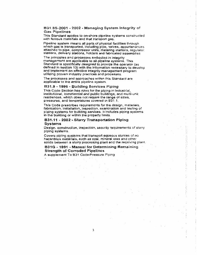
B31.8S-2001 - 2002 - Managing System Integrity of Gas Pipelines This Standard applies to on-shore pipeline systems constructed with ferrous materials and that transport gas.
Pipeline system means all parts of physical facilities through which gas is transported, including pipe, valves, appurtenances attached to pipe, compressor units, metering stations, regulator stations, delivery stafions, holders and fabricated assemblies
The principles and processes embodied in integrity management are applicable to all pipeline systems. This Standard is specifically designed to provide the operator (as defined In section 13) with the information necessary to develop and implement an effective integrity management program utilizing proven industry practices and processes.
The processes and approaches within this Standard are applicable to the entire pipeline system.
B31.9 - 1996 - Building Services Piping This Code Section has rules for the piping in industrial, institutional, commercial and public buildings, and multi-unit residences, which does not require the range of sizes, pressures, and temperatures covered in B31 1.
This Code prescribes requirements for the design, materials, fabrication, installation, inspection, examination and testing of piping systems for building services. It includes piping systems in the building or within the property limits.
B31.11 - 2002 - Slurry Transportation Piping Systems Design, construction, inspection, security requirements of slurry piping systems.
Covers piping systems that transport aqueous slurries of no hazardous materials, such as coal, mineral ores and other solids between a slurry processing plant and the receiving plant.
B31G - 1991 - Manual for Determining Remaining Strength of Corroded Pipelines A supplement To B31 Code-Pressure Piping
3
ATTACHMENT F
ASME B31 1 - 2007 POWER PIPING
•ASME B31.1 a - 2008 ADDENDA
•ASME B31,1 b - 2009 ADDENDA
A5807A
The American Society o echanical Engineers 4L, Three Park Avenue • New York, NY 10 016
Addenda to ASME B31.1-2007 Power Piping
4111111111Malinswomm■
ASA% Code for Pressure Piping, 831
AN AMERICAN NATIONAL STANDARD

ASME B31.1a-2008
Following approval by the B31 Committee and ASME, and after public review, ASME B31.1a-2008 was approved by the American National Standards Institute on March 3, 2008.
Addenda to ASME B31,1-2007 are issued in the form of replacement pages. Revisions, additions, and deletions are incorporated directly into the affected pages. It is advisable, however, that this page, the Addenda title and copyright pages, and all replaced pages be retained for reference.
SUMMARY OF CHANGES
This is the first Addenda to be published to ASME 531.1-2007.
Replace or insert the pages listed. Changes given below are identified on the pages by a margin note, (A08), placed next to the affected area. Revisions introduced in ASME 531.1-2007 ate indicated by (07). The pages not listed are the reverse sides of the listed pages and contain no changes.
Page
vii-ix
Location
Committee Roster
Change
Updated
3 Fig. 100.1.2(B) (1) In left half of drawing, near para. 122.1.7(D) callouts, two circles indicating jurisdiction and responsibility corrected by errata to be open
(2) In right half of drawing, two references to para. 122,1.7 deleted and new one added by errata
10, 10.1 101.2.5 Added
13 Equation (2) Equation and its nomenclature revised
16-16,2 102.4.7
104.1.1
104.1.2
Added
Added
Title revised
Table 102A.7 Added
18, 18.1 104.1.4 Added
19 104.3.1(D.2) (1) D, deleted (6 b 6 '(19c1-.4 1 (2) Do and Do added
23 104.3.1(G.4) Revised
104,3.1(G5) Revised
24 Fig. 104.3.1(G) Callouts revised
41, 42 119.10.1 Nomenclature for E, and Eh revised
50 Fig. 122.1.7(C) Callouts revised
62, 62-1 123.2.2(C) Added
123.4 Added
(c)

Page Location Change
124.4 In text table, for last three entries, cross- references corrected by errata
1245 In text table, for last three entries, cross- references corrected by errata
63 124.6(C) In text table, for sixth through eighth entries, cross-references corrected by errata
67 Table 126.1 (1) Under Forgings, for ASTM B 462, title revised
(2) Under Seamless Pipe and Tube, AS1M B 690 added
68 Table 126.1 (1) Under Welded Pipe and Tube, second entry corrected by errata to read B 608
(2) ASTM B 675, B 676, and B 804 added (3) Under Plate, Sheet, and Strip, ASTM
B 171 added, B 402 deleted, and B 688 added
(4) Under Rods, Bars, and Shapes, ASTM B 691 added
70 Table 126.1 Under National Fire Codes, NFPA 54/ ANSI 7773 1 added, NPPA 85 added, NFPA 1963 revised, and NFPA 8503 deleted
75 127.4.3 Revised
80 1275.3(B) Last paragraph revised
87-88.1 Table 132 P.No. 5B revised
93 Table 136.4 General Note (f) added
118 Table A-2 Under Electric Fusion Welded Pipe — Filler Metal Added, for both A 691 Grade 91 lines, Note (17) references deleted by errata
132, 133 Table A-3 Under Seamless Pipe and Tube, Ferritic/ Austenitic, A 789 and A 790 S32205 and 832750 added
138, 139 Table A-3 Under Welded Pipe and Tube — Without Filler Metal, Ferritic/Austenitic, A 789 and A 790 S32205 and S32750 added
144, 145 Table A-3 Under Plate, Sheet, and Strip, Ferritic/ Austenitic, A 240 S32205 and S32750 added
148, 149 Table A-3 Under Forgings, Ferritic/Austenitic, A 182 Grades F60 and F53 added
150, 151 Table A-3 Under Fittings, Ferritic/Austenitic, A 815 S32205 added
154, 155 Table A-3 Under Bolts, Nuts, and Studs, Austenitic, for A153 Grade 660, stress values for 200°F through 1,000°F added
(d)
Page Location Change
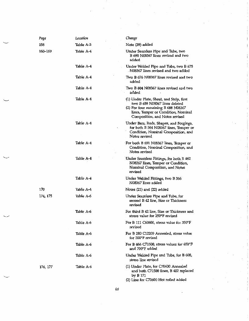
158 11:6le A-3 Note (39) added
160-169 Table A-4 Under Seamless Pipe and Tube, two B 690 N08367 lines revised and two added
Table A-4 Under Welded Pipe and Tube, two B 675 N08367 lines revised and two added
Table A-4 Two B 676 N08367 lines revised and two added
Table A-4 Two B 804 N08367 lines revised and two added
Table A-4 (1) Under Plate, Sheet, and Strip, first two B 688 N08367 lines deleted
(2) For four remaining B 688 N08367 lines, Temper or Condition, Nominal Composition, and Notes revised
Table A-4 Under Bars, Rods, Shapes, and Forgings, for both B 564 N08367 lines, Temper or Condition, Nominal Composition, and Notes revised
170
174, 175
176, 177
Table A-4
Table A-4
Table A-4
Table A-4
Table A-6
Table A-6
Table A-6
Table A-6
Table A-6
Table A-6
Table A-6
For both B 691 N08367 lines, Temper or Condition, Nominal Composition, and Notes revised
Under Seamless Fittings, for both B 462 N08367 lines, Temper or Condition, Nominal Composition, and Notes revised
Under Welded Fittings, two B 366 N08367 lines added
Notes (21) and (22) added
Under Seamless Pipe and Tube, for second B 42 line, Size or Thickness revised
For third B 42 line, Size or Thickness and stress value for 250°F revised
For B 111 C60800, stress value for 350°F revised
For B 280 C12200 Annealed, stress value for 200°F revised
For B 466 C71500, stress values for 650°F and 700°F added
Under Welded Pipe and Thbe, for B 608, stress line revised
(1) Under Plate, for C70600 Annealed and both C71500 lines, B 402 replaced by B 171
(2) Line for C70600 Hot rolled added
(e)
Page Location
Table A-6
Change
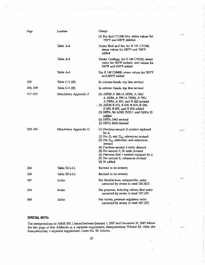
(3) For first C71500 line, stress values for 750°F and 800°F deleted
Under Rod and Bar, for B 151 C71500, stress values for 650°F and 700°F added
Table A-6 Under Castings, for B 148 C95200, stress value for 500°F revised, and values for 550°F and 600°F added
Table A-6 For B 148 C95400, stress values for 550°F and 600°F added
205 Table C-1 (SI) In column heads, top line revised
208, 209 Table C-2 (SI) In column heads, top line revisd
217-219 Mandatory Appendix P (1) ASTM A 182/A 182M, A 240/ A 240M, A 789/A 789M, A 790/ A 790M, A 815, and B 462 revised
, (2) ASTM B 171, B 675, B 676, B 688, B 690, B 691, and B 804 added
(3) NFPA 54/ANSI Z723.1 and NFPA 85 added
(4) NPPA 1963 revised (5) NEPA 8503 deleted
220-226 Mandatory Appendix G (1) Previous second D symbol replaced by di
(2) For Do and Doo, references revised (3) For Dol„ definition and references
revised (4) Yrevious second d entry deleted (5) For second E, SI units revised (6) Previous first r symbol replaced by q (7) For second R, references revised (8) W added
264 Table III-4.3.1 Revised in its entirety
265 Table M4.3.2 Revised in its entirety
297 Index For flexible hose, nonmetallic, entry corrected by errata to read 105.3(D)
298 Index For pressure, reducing valves, first entry corrected by errata to read 107.1(F)
300 Index For valves, pressure regulator, entry corrected by errata to read 107.1(F)
SPECIAL NOTE:
The interpretations to ASME B31.1 issued between January 1, 2007 and December 31, 2007 follow the last page of this Addenda as a separate supplement, Interpretations Volume 43. After the Interpretations, a separate supplement, Cases No. 33, follows.

ASME B31
o-A4.
The American Society o Mechanical Engineers ;71:: ■:; TU
11111111!10111
Addenda to ASME B31.1-2007 Power Piping
ASME Code for Pressure Piping, 631
AN AMERICAN NATIONAL STANDARD

ASME B31.1b-2009
Following approval by the B31 Committee and AS/vIE, and after public review, ASME B31.1b-2009 was approved by the American National Standards Institute on June 3, 2009.
Addenda to ASME B31.1-2007 are issued in the form of replacement pages. Revisions, additions, and deletions are incorporated directly into the affected pages. It is advisable, however, that this page, the Addenda title and copyright pages, and all replaced pages be retained for reference.
SUMMARY OF CHANGES
This is the second Addenda to be published to ASME B31.1-2007.
Replace or insert the pages listed. Changes given below are identified on the pages by a margin note, (A09), placed next to the affected area. Revisions introduced in ASME B31.1-2007 are indicated by (07) and revisions in ASME B31.1a-2008 are indicated by (A08). The pages not listed are the reverse sides of the listed pages and contain no changes.
Page Location Change
vii—ix Committee Roster Updated
1 100.1.2(A) Third paragraph revised
2 Fig. 100.1.2(A.1) Former Fig. 100.1.2(A) redesignated and title revised
2.1 Fig. 100.1.2(A.2) Added
5, 6 100.2 Definitions of capacitor discharge welding and creep strength enhanced ferritic steel added
10-12 101.5.2 Revised
101.5.3 Revised
43 121.2(G) Revised
44 121.7.2(A) First paragraph revised
48, 48.1 122.1.4(A.1) Revised
62 124.2(D) Revised
62.1, 63 124.5 In-text table revised
124.6(C) In-text table revised
65 Table 126.1 ASCE/SEI 7 added
69 Table 126.1 (1) MSS SP-88 added (2) Title of MSS SP-95 revised
70 Table 126.1 AWS D10.10 added
82 Table 129.3.2 Under Material, fourth entry revised
83-84.1 131.4.9 Added
131.5 Deleted
131.6.1(A) Revised
(c)

Page Location Change
131.6.1(C) Revised
131.62 Added
132.1 (1) Existing paragraph designated as 132.1.1
(2) Paragraph 1321.2 added
132.3.3 Added
132.5 Revised
87, 882 Table 132 P-No. 5B Gr. No. 2 corrected by errata to read P-No. 15E, Gr. No. 1 in first column and P-No. 15E in General Note (b)
89, 90 132.7 Revised
92 136.4.1 Revised'
102, 103 Table A-1 Under Electric Resistance Welded Pipe and Tube, A 226 deleted
110, 111 Table A-1 Under Plate, A 515 Grade 55 deleted
114, 115 Table A-2 Under Seamless Pipe and Tube, for A 213 Grade T91 and A 335 Grade P91, P-No. revised
118, 119 Table A-2 (1) Under Electric Fusion Welded Pipe — Filler Metal Added, for A 691 Grade 91, P-No. revised
(2) Under Plate, for A 387 Grade 91, P-No. revised
120, 121 Table A-2 (1) Under Forgings, for A 336 Grade F91, P-No. revised
(2) Under Wrought Fittings (Seamless and Welded), for A 234 Grade WP91, P-No. revised
122, 123 Table A-2 Under Castings, for A 217 Grade C12A, P-No. revised
128, 129 Table A-3 Under Seamless Pipe and Tube, Austenitic, for A 312 S31254, Specified Minimum Tensile, Specified Minimum Yield, and all stress values revised
132, 133 Table A-3 Under Centrifugally Cast Pipe, Austenitic, A 452 deleted
136, 137 Table A-3 Under Welded Pipe and Tube — Without Filler Metal, Austenitic, for A 312 S31254, Specified Minimum Tensile, Specified Minimum Yield, and all stress values revised
140, 141 Table A-3 Under Welded Pipe — Filler Metal Added, Austenitic, for A 358 S31254, Specified Minimum Tensile, Specified Minimum Yield, and all stress values revised for existing four lines and four new lines added
(d)

Page Location Change
144, 145 Table A-3 Under Plate, Sheet, and Strip, Austenitic, for A 240 331254, Specified Minimum Tensile, Specified Minimum Yield, and all stress values revised for existing two lines and two new lines added
148, 149 Table A-3 Under Fittings (Seamless and Welded), Austenitic, A 403 WP331254 added
154, 155 Table A-3 Under Bar, Austenitic, A 479 531254 added
160, 161 Table A-4 Under Seamless Pipe and Tube, for B 622 R30556, stress values italicized at 1,150°F for second line and at 1,200°F for both lines
162, 163 Table A-4 Under Welded Pipe and Tube, for B 619 R30556, stress values italicized at 1,100°F for second line, and at 1,150°F and 1,200°F for both lines
Table A-4 For B 626 R30556, stress values italicized at 1,100°F for second line, and at 1,150°F and 1,200°F for both lines
164, 165 Table A-4 Under Plate, Sheet, and Strip, for B 435 R30556, stress values italicized at 1,150°F for second line and at 1,200°F for both lines
166, 167 Table A-4 Under Bars, Rods, Shapes, and Forgings, for B 572 R30556, stress values italicized at 1,150°F for second line and at 1,200°F for both lines
168, 169 Table A-4 (1) Under Seamless Fittings, for B 366 R30556, stress values italicized at 1,150°F for second line and at 1,200°F for both lines
(2) Under Welded Fittings, for B 366 R30556, stress values italicized at 1,100°F for second line, and at 1,150°F and 1,200°F for both lines
186, 187 Table A-8 Under Seamless Pipe and Tube, B 622 R30556 added
188-191 Table A-8 (1) Under Welded Pipe and Tube - Without Filler Metal, B 619 R30556 and B 626 R30556 added
(2) Plate, Sheet, and Strip heading and B 435 R30556 added
(3) Under Bars, Rods, and Shapes, B 572 R30556 added .
(4) Under Fittings (Seamless and Welded), B 366 R30556 added
(5) Notes (6) and (7) added
217 Mandatory Appendix F (1) ASCE/SET 7 added
(e)
Page Location Change
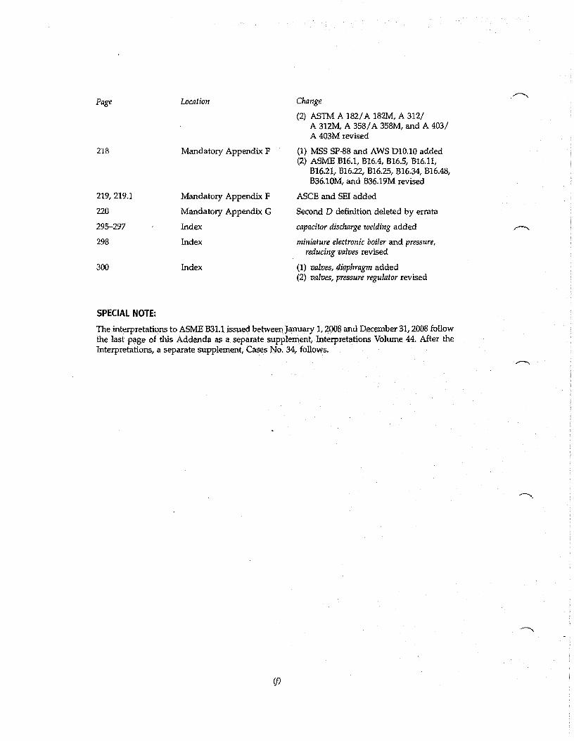
(2) ASTM A 182/A 182M, A 312/ A 312M, A 358/A 358M, and A 403/ A 403M revised
218 Mandatory Appendix F (1) MSS SP-88 and AWS D10.10 added (2) ASME B16.1, B16.4, B16.5, B16.11,
B16.21, 616.22, 1316.25, B16.34, 616.48, 636.10M, and B36.19M revised
219, 219.1 Mandatory Appendix F ASCE and SET added
220 Mandatory Appendix G Second D definition deleted by errata
295-297 Index capacitor discharge welding added
298 Index miniature electronic boiler and pressure, reducing valves revised
300 Index (1) valves, diaphragm added (2) valves, pressure regulator revised
SPECIAL NOTE:
The interpretations to ASME B31.1 issued between January 1, 2008 and December 31, 2008 follow the last page of this Addenda as a separate supplement, Interpretations Volume 44. After the Interpretations, a separate supplement, Cases No. 34, follows.
(9