Publisher: LuK GmbH & Co. - Schaeffler Group
14
Transcript of Publisher: LuK GmbH & Co. - Schaeffler Group


Publisher: LuK GmbH & Co.Industriestrasse 3 • D -77815 Bühl/Baden
Telephon +49 (0) 7223 / 941 - 0 • Fax +49 (0) 7223 / 2 69 50Internet: www.LuK.de
Editorial: Ralf Stopp, Christa Siefert
Layout: Vera WestermannLayout support: Heike Pinther
Print: Konkordia GmbH, BühlDas Medienunternehmen
Printed in Germany
Reprint, also in extracts, withoutauthorisation of the publisher forbidden.
Foreword
Innovations are shaping ourfuture. Experts predict that therewill be more changes in the fieldsof transmission, electronics andsafety of vehicles over the next15 years than there have beenthroughout the past 50 years. Thisdrive for innovation is continuallyproviding manufacturers and sup-pliers with new challenges and isset to significantly alter our worldof mobility.
LuK is embracing these challen-ges. With a wealth of vision andengineering performance, ourengineers are once again provingtheir innovative power.
This volume comprises papersfrom the 7th LuK Symposium andillustrates our view of technicaldevelopments.
We look forward to some intere-sting discussions with you.
Bühl, in April 2002
Helmut Beier
Presidentof the LuK Group
Content
LuK SYMPOSIUM 2002
1 DMFW – Nothing New? . . . . . . . . . . . . . . . . . . . . . . . . . . . . . . . . . . 5
2 Torque Converter Evolution at LuK . . . . . . . . . . . . . . . . . . . . . . . 15
3 Clutch Release Systems . . . . . . . . . . . . . . . . . . . . . . . . . . . . . . . . 27
4 Internal Crankshaft Damper (ICD). . . . . . . . . . . . . . . . . . . . . . . . . 41
5 Latest Results in the CVT Development. . . . . . . . . . . . . . . . . . . . 51
6 Efficiency-Optimised CVT Clamping System . . . . . . . . . . . . . . . 61
7 500 Nm CVT . . . . . . . . . . . . . . . . . . . . . . . . . . . . . . . . . . . . . . . . . . 75
8 The Crank-CVT . . . . . . . . . . . . . . . . . . . . . . . . . . . . . . . . . . . . . . . . 89
9 Demand Based Controllable Pumps. . . . . . . . . . . . . . . . . . . . . . . 99
10 Temperature-controlled Lubricating Oil Pumps Save Fuel . . . 113
11 CO2 Compressors . . . . . . . . . . . . . . . . . . . . . . . . . . . . . . . . . . . . 123
12 Components and Assemblies for Transmission Shift Systems135
13 The XSG Family . . . . . . . . . . . . . . . . . . . . . . . . . . . . . . . . . . . . . . 145
14 New Opportunities for the Clutch?. . . . . . . . . . . . . . . . . . . . . . . 161
15 Electro-Mechanical Actuators. . . . . . . . . . . . . . . . . . . . . . . . . . . 173
16 Think Systems - Software by LuK. . . . . . . . . . . . . . . . . . . . . . . . 185
17 The Parallel Shift Gearbox PSG . . . . . . . . . . . . . . . . . . . . . . . . . 197
18 Small Starter Generator – Big Impact . . . . . . . . . . . . . . . . . . . . . 211
19 Code Generation for Manufacturing. . . . . . . . . . . . . . . . . . . . . . 225
WESTEV
10 Temperature-controlled Lubricating Oil Pumps Save Fuel . . . 113
113LuK SYMPOSIUM 2002
Temperature-controlled Lubricating Oil Pumps Save Fuel
Heiko Schulz-AndresDirk Kamarys
10
10 Temperature-controlled Lubricating Oil Pumps Save Fuel
114 LuK SYMPOSIUM 2002
IntroductionReducing fuel consumption in automobileswill continue to be a major focus for develop-ment in the automotive industry in the future.In addition to developing new technologies(e.g. direct injection), it will become increasin-gly important to optimize existing compon-ents. This allows significant savings potentialto be realized without the immense costs thatnew systems can cause. The key word hereis ‘requirement-oriented auxiliaries’.
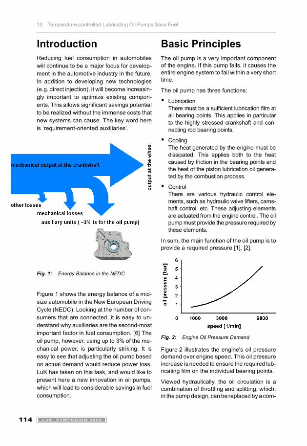
Fig. 1: Energy Balance in the NEDC
Figure 1 shows the energy balance of a mid-size automobile in the New European DrivingCycle (NEDC). Looking at the number of con-sumers that are connected, it is easy to un-derstand why auxiliaries are the second-mostimportant factor in fuel consumption. [6] Theoil pump, however, using up to 3% of the me-chanical power, is particularly striking. It iseasy to see that adjusting the oil pump basedon actual demand would reduce power loss.LuK has taken on this task, and would like topresent here a new innovation in oil pumps,which will lead to considerable savings in fuelconsumption.
Basic PrinciplesThe oil pump is a very important componentof the engine. If this pump fails, it causes theentire engine system to fail within a very shorttime.
The oil pump has three functions:
� LubricationThere must be a sufficient lubrication film atall bearing points. This applies in particularto the highly stressed crankshaft and con-necting rod bearing points.
� CoolingThe heat generated by the engine must bedissipated. This applies both to the heatcaused by friction in the bearing points andthe heat of the piston lubrication oil genera-ted by the combustion process.
� ControlThere are various hydraulic control ele-ments, such as hydraulic valve lifters, cams-haft control, etc. These adjusting elementsare actuated from the engine control. The oilpump must provide the pressure required bythese elements.
In sum, the main function of the oil pump is toprovide a required pressure [1], [2].
Fig. 2: Engine Oil Pressure Demand
Figure 2 illustrates the engine’s oil pressuredemand over engine speed. This oil pressureincrease is needed to ensure the required lub-ricating film on the individual bearing points.
Viewed hydraulically, the oil circulation is acombination of throttling and splitting, which,in the pump design, can be replaced by a com-
10 Temperature-controlled Lubricating Oil Pumps Save Fuel
115LuK SYMPOSIUM 2002
pensating choke. From this, it is possible tocalculate the flow rate required for the pres-sure buildup.
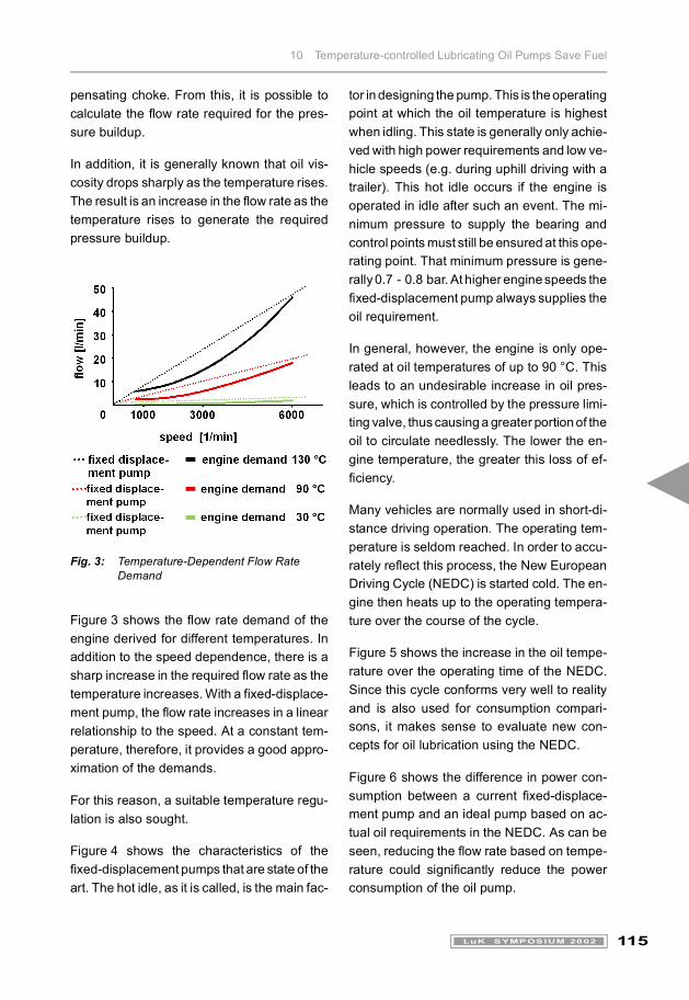
In addition, it is generally known that oil vis-cosity drops sharply as the temperature rises.The result is an increase in the flow rate as thetemperature rises to generate the requiredpressure buildup.
Fig. 3: Temperature-Dependent Flow Rate Demand
Figure 3 shows the flow rate demand of theengine derived for different temperatures. Inaddition to the speed dependence, there is asharp increase in the required flow rate as thetemperature increases. With a fixed-displace-ment pump, the flow rate increases in a linearrelationship to the speed. At a constant tem-perature, therefore, it provides a good appro-ximation of the demands.
For this reason, a suitable temperature regu-lation is also sought.
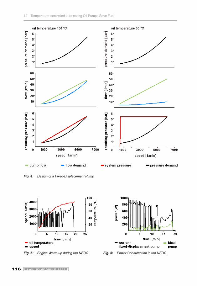
Figure 4 shows the characteristics of thefixed-displacement pumps that are state of theart. The hot idle, as it is called, is the main fac-
tor in designing the pump. This is the operatingpoint at which the oil temperature is highestwhen idling. This state is generally only achie-ved with high power requirements and low ve-hicle speeds (e.g. during uphill driving with atrailer). This hot idle occurs if the engine isoperated in idle after such an event. The mi-nimum pressure to supply the bearing andcontrol points must still be ensured at this ope-rating point. That minimum pressure is gene-rally 0.7 - 0.8 bar. At higher engine speeds thefixed-displacement pump always supplies theoil requirement.
In general, however, the engine is only ope-rated at oil temperatures of up to 90 °C. Thisleads to an undesirable increase in oil pres-sure, which is controlled by the pressure limi-ting valve, thus causing a greater portion of theoil to circulate needlessly. The lower the en-gine temperature, the greater this loss of ef-ficiency.
Many vehicles are normally used in short-di-stance driving operation. The operating tem-perature is seldom reached. In order to accu-rately reflect this process, the New EuropeanDriving Cycle (NEDC) is started cold. The en-gine then heats up to the operating tempera-ture over the course of the cycle.
Figure 5 shows the increase in the oil tempe-rature over the operating time of the NEDC.Since this cycle conforms very well to realityand is also used for consumption compari-sons, it makes sense to evaluate new con-cepts for oil lubrication using the NEDC.
Figure 6 shows the difference in power con-sumption between a current fixed-displace-ment pump and an ideal pump based on ac-tual oil requirements in the NEDC. As can beseen, reducing the flow rate based on tempe-rature could significantly reduce the powerconsumption of the oil pump.
10 Temperature-controlled Lubricating Oil Pumps Save Fuel
116 LuK SYMPOSIUM 2002
Fig. 4: Design of a Fixed-Displacement Pump
Fig. 5: Engine Warm-up during the NEDC Fig. 6: Power Consumption in the NEDC
10 Temperature-controlled Lubricating Oil Pumps Save Fuel
117LuK SYMPOSIUM 2002
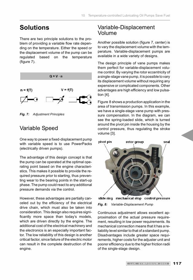
SolutionsThere are two principle solutions to the pro-blem of providing a variable flow rate depen-ding on the temperature. Either the speed orthe displacement volume of the pump can beregulated based on the temperature(figure 7).
Fig. 7: Adjustment Principles
Variable Speed
One way to power a fixed-displacement pumpwith variable speed is to use PowerPacks(electrically driven pumps).
The advantage of this design concept is thatthe pump can be operated at the optimal ope-rating point based on the engine characteri-stics. This makes it possible to provide the re-quired pressure prior to starting, thus preven-ting wear to the bearing points in the start-upphase. The pump could react to any additionalpressure demands via the control.
However, these advantages are partially can-celed out by the efficiency of the electricaldrive chain, which must also be taken intoconsideration. This design also requires signi-ficantly more space than today’s models,which are driven directly by the engine. Theadditional cost of the electrical machinery andthe electronics is an especially important fac-tor. The low reliability of this design is anothercritical factor, since failure of the electric motorcan result in the complete destruction of theengine.
Variable-Displacement VolumeAnother possible solution (figure 7, center) isto vary the displacement volume with the tem-perature. Variable-displacement pumps areavailable in a wide variety of designs.
The design principle of vane pumps makesthem perfect for variable-displacement volu-me control. By varying the rotor eccentricity ofa single-stage vane pump, it is possible to varyits displacement volume without requiring anyexpensive or complicated components. Otheradvantages are high efficiency and low pulsa-tion [4].
Figure 8 shows a production application in thearea of transmission pumps. In this example,we have a single-stage vane pump with pres-sure compensation. In the diagram, we cansee the spring-loaded slide, which is turnedaround the pivot pin inside the housing by thecontrol pressure, thus regulating the strokevolume [3].
Fig. 8: Variable-Displacement Pump
Continuous adjustment allows excellent ap-proximation of the actual pressure require-ment, resulting in low power requirements. Itsmechanical connection means that it has a re-liability level similar to that of a standard pump.Disadvantages include greater space requi-rements, higher costs for the adjuster unit andpoorer efficiency due to the higher friction radiiof the single-stage design.
10 Temperature-controlled Lubricating Oil Pumps Save Fuel
118 LuK SYMPOSIUM 2002
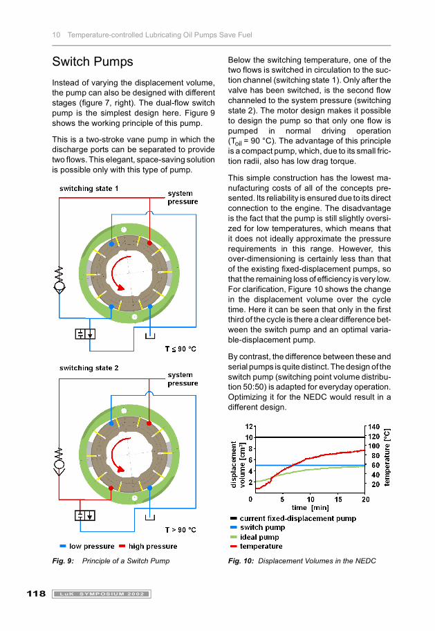
Switch PumpsInstead of varying the displacement volume,the pump can also be designed with differentstages (figure 7, right). The dual-flow switchpump is the simplest design here. Figure 9shows the working principle of this pump.
This is a two-stroke vane pump in which thedischarge ports can be separated to providetwo flows. This elegant, space-saving solutionis possible only with this type of pump.
Fig. 9: Principle of a Switch Pump
Below the switching temperature, one of thetwo flows is switched in circulation to the suc-tion channel (switching state 1). Only after thevalve has been switched, is the second flowchanneled to the system pressure (switchingstate 2). The motor design makes it possibleto design the pump so that only one flow ispumped in normal driving operation(Toil = 90 °C). The advantage of this principleis a compact pump, which, due to its small fric-tion radii, also has low drag torque.
This simple construction has the lowest ma-nufacturing costs of all of the concepts pre-sented. Its reliability is ensured due to its directconnection to the engine. The disadvantageis the fact that the pump is still slightly oversi-zed for low temperatures, which means thatit does not ideally approximate the pressurerequirements in this range. However, thisover-dimensioning is certainly less than thatof the existing fixed-displacement pumps, sothat the remaining loss of efficiency is very low.For clarification, Figure 10 shows the changein the displacement volume over the cycletime. Here it can be seen that only in the firstthird of the cycle is there a clear difference bet-ween the switch pump and an optimal varia-ble-displacement pump.
By contrast, the difference between these andserial pumps is quite distinct. The design of theswitch pump (switching point volume distribu-tion 50:50) is adapted for everyday operation.Optimizing it for the NEDC would result in adifferent design.
Fig. 10: Displacement Volumes in the NEDC

10 Temperature-controlled Lubricating Oil Pumps Save Fuel
119LuK SYMPOSIUM 2002
Fig. 11: Power Consumption in the NEDC
Fig. 12: Evaluation of the Design Concepts
To evaluate the design concepts the powerconsumption in the NEDC was determined byusing a simulation model. The results areshown in figure 11. The power consumption ofall of the concepts are significantly below tho-se of the state of the art pump. For a mid-sizedvehicle with a power requirement of 10 kW inthe NEDC, this reduction corresponds to a fuelsaving of approximately 1.5%.
Figure 12 shows a summary of all of the con-cept evaluations.
The concept with the best cost-benefit ratiowas selected for design implementation.Another deciding factor was the ability to im-plement the concept quickly in production.The dual-flow switch pump was selected forimplementation based on this evaluation andon the positive trials with switch pumps.
Design Implementation of the Switch Pump
Fig. 13: Pump Design
Figure 13 shows how the switch pump is in-tegrated in a current oil pump housing, in thiscase built as an on-axis pump. The pump sitson the engine block between the main bearingand the belt pulley for the power take-off. Thecrankshaft drives the rotor directly. The rotorgroup is designed as a two-stage vane cellwith 10 vanes. The stroke contour reflects theLuK standard for power steering pumps, as isthe hydraulic vane extension known from thehigh-pressure pumps, to minimize leakage.The pump is designed so that the channel gui-de is optimal for the dominant switchingstate 1 (only one flow active). The pressure li-miting valve can be made considerably smal-ler than in the current production unit, sincethe maximum volume flowing through the val-ve has also been reduced.
concept Pow
erPa
ck
varia
ble
disp
lace
men
t
switc
h pu
mp
close to pressure demand
powerconsumption
operating safety
installation space
cost
10 Temperature-controlled Lubricating Oil Pumps Save Fuel
120 LuK SYMPOSIUM 2002
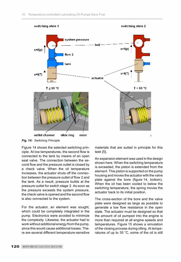
Fig. 14: Switching Principle
Figure 14 shows the selected switching prin-ciple. At low temperatures, the second flow isconnected to the tank by means of an openseat valve. The connection between the se-cond flow and the pressure outlet is closed bya check valve. When the oil temperatureincreases, the actuator shuts off the connec-tion between the pressure outlet of flow 2 andthe tank. As a result, pressure builds at thepressure outlet for switch stage 2. As soon asthe pressure exceeds the system pressure,the check valve is opened and the second flowis also connected to the system.
For the actuator, an element was sought,which could be completely integrated in thepump. Electronics were avoided to minimizethe complexity. Likewise, the actuator had towork without additional energy from the pump,since this would cause additional losses. The-re are several different temperature-sensitive
materials that are suited in principle for thistask [5].
An expansion element was used in the designshown here. When the switching temperatureis exceeded, the piston is extended from theelement. This piston is supported on the pumphousing and moves the actuator with the valveplate against the bore (figure 14, bottom).When the oil has been cooled to below theswitching temperature, the spring moves theactuator back to its initial position.
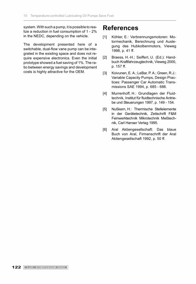
The cross-section of the bore and the valveplate were designed as large as possible togenerate a low flow resistance in the openstate. The actuator must be designed so thatthe amount of oil pumped into the engine ismore than required at all engine speeds andtemperatures. Figure 15 shows a simulationof the closing process during idling. At tempe-ratures of up to 35 °C, some of the oil is still
10 Temperature-controlled Lubricating Oil Pumps Save Fuel
121LuK SYMPOSIUM 2002
sent through the pressure limiting valve (PLV).Above this oil temperature, the full flow volumeis pumped to the engine. The pressure buildupdecreases as the temperature rises. Before itcan fall below the minimum pressure, thepump switches to the second stage and sup-plies sufficient oil to the engine even at highertemperatures.
Due to the expansion element, there is a hy-steresis between the temperatures to switchthe second stage on and off. This also increa-ses safety during the transition between hotand normal operation. The simulation showsthat the requirement set in the beginning is ful-filled.
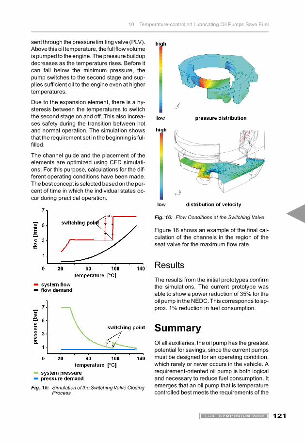
The channel guide and the placement of theelements are optimized using CFD simulati-ons. For this purpose, calculations for the dif-ferent operating conditions have been made.The best concept is selected based on the per-cent of time in which the individual states oc-cur during practical operation.
Fig. 15: Simulation of the Switching Valve Closing Process
Fig. 16: Flow Conditions at the Switching Valve
Figure 16 shows an example of the final cal-culation of the channels in the region of theseat valve for the maximum flow rate.
ResultsThe results from the initial prototypes confirmthe simulations. The current prototype wasable to show a power reduction of 35% for theoil pump in the NEDC. This corresponds to ap-prox. 1% reduction in fuel consumption.
SummaryOf all auxiliaries, the oil pump has the greatestpotential for savings, since the current pumpsmust be designed for an operating condition,which rarely or never occurs in the vehicle. Arequirement-oriented oil pump is both logicaland necessary to reduce fuel consumption. Itemerges that an oil pump that is temperaturecontrolled best meets the requirements of the
10 Temperature-controlled Lubricating Oil Pumps Save Fuel
122 LuK SYMPOSIUM 2002
system. With such a pump, it is possible to rea-lize a reduction in fuel consumption of 1 - 2%in the NEDC, depending on the vehicle.
The development presented here of aswitchable, dual-flow vane pump can be inte-grated in the existing space and does not re-quire expensive electronics. Even the initialprototype showed a fuel saving of 1%. The ra-tio between energy savings and developmentcosts is highly attractive for the OEM.
References[1] Köhler, E.: Verbrennungsmotoren: Mo-
tormechanik, Berechnung und Ausle-gung des Hubkolbenmotors, Vieweg1998, p. 41 ff.
[2] Braess, H.-H.; Seiffert, U. (Ed.): Hand-buch Kraftfahrzeugtechnik, Vieweg 2000,p. 157 ff.
[3] Koivunen, E. A.; LeBar, P. A.; Green, R.J.:Variable Capacity Pumps, Design Prac-tices: Passenger Car Automatic Trans-missions SAE 1994, p. 685 - 688.
[4] Murrenhoff, H.: Grundlagen der Fluid-technik, Institut für fluidtechnische Antrie-be und Steuerungen 1997, p. 149 - 154.
[5] Nußkern, H.: Thermische Stellelementein der Gerätetechnik, Zeitschrift F&MFeinwerktechnik Mikrotechnik Meßtech-nik, Carl Hanser Verlag 1995.
[6] Aral Aktiengesellschaft: Das blaueBuch von Aral, Firmenschrift der AralAktiengesellschaft 1992, p. 50 ff.