Published Online December 2017 in IJEAST ( ...TESMA208,IJEAST.pdf · Koyunbaba and Yilmaz (2012)...
12
International Journal of Engineering Applied Sciences and Technology, 2017 Vol. 2, Issue 8, ISSN No. 2455-2143, Pages 58-69 Published Online December 2017 in IJEAST (http://www.ijeast.com) 58 Periodic Modeling and Effect of Design Parameters of Semitransparent Photovoltaic Thermal Trombe Wall (SPVT-TW) with Air Duct Firehun Taffesse a *, Neha Dimri a , Arvind Tiwari b , Emran Khan c , G. N. Tiwari c and T.S. Bhatti a a Centre for Energy Studies, Indian Institute of Technology Delhi, Hauz Khas, New Delhi, India b Department of Electrical Engineering, College of Engineering, Qassim University, Buraidah, Saudi Arabia c Department of Mechanical Engineering, Faculty of Engineering and Technology, Jamia Millia Islamia, New Delhi, India Abstract— Trombe wall is one of the unique features in passive solar house development, which facilitates heat storage. A mathematical model of semitransparent photovoltaic thermal Trombe wall (SPVT-TW) with air ducts (or vents) has been derived in this paper, for a single room of 30 m 2 dimension, for winter season of New Delhi, India. The model is derived considering the energy balance equations taking into account the periodic nature of solar radiation and ambient temperature. Further, the effect of several parameters namely, thickness of wall, mass flow rate, packing factor, absorptivity and transmittivity of PV module on room air temperature and thermal stability have been examined. The performance of vented SPVT- TW has been compared with SPVT-TW without vent. The results illustrate that the thickness of the room should be 0.3 m, with a corresponding thermal load leveling of 0.0038, for vented SPVT-TW, from a thermal stability point of view. Also, the room air temperature of 45 o C can be reached in case of vented SPVT-TW, which is higher than SPVT-TW without vent. Keywords— Periodic modeling, heating the room, Trombe wall, Photovoltaic thermal (PVT) I. INTRODUCTION Passive solar heating can be utilized for maintaining a pleasant temperature within a building without the use of conventional energy sources. There are a wide range of studies and investigations pertaining to Trombe wall for different seasons and climatic conditions. Smolec and Thomas (1991) calculated the temperature distribution in Trombe wall theoretically, using PASOLE model and compared the results with experimental data. Mansour et. al.(1991) studied the convective laminar heat transfer between the Trombe wall’s channel surfaces and developed a mathematical model for temperature profiles, pressure defects and velocity using new approximate methods. Photovoltaic Trombe wall is not only used for thermal heating, but also for thermal cooling of buildings. Gan (1998) studied the cooling of building in summer condition using Trombe wall. They used computational fluid dynamics with renormalization group k-Ɛ turbulence model to predict the flow rate and buoyant flow. Further, they investigated the effects of various parameters such as wall height, wall insulation, wall and glazing separation and glazing type. Finally, it was concluded that the inner surface of a Trombe wall should be insulated to allow for cooling as well as to prevent overheating of air due to heat radiation from inner portion of the wall. Furthermore, the design parameters of photovoltaic module affect thermal utilization as well as electrical efficiency. Jie et al. (2007) have studied a model of PV glass panel and of Photovoltaic Trombe wall (PV-TW). The electrical performance and temperature distribution of PV-TW was obtained. They concluded that the temperature difference between the components in the presence and absence of PV glass panel reaches the highest value of 10.6 o C and the electrical efficiency increases by 10%. Jiang et. al. (2008) have discussed the effects of photovoltaic coverage ratio. As the coverage ratio increases, the electrical energy output and total efficiency of PV-TW increases, however the thermal efficiency and interior temperature decreases. Koyunbaba and Yilmaz (2012) examined different arrangements of single glass, double glass and a Si-semitransparent PV module integrated with Trombe wall in Izmir, Turkey. For transient analysis, a two-dimensional model using computational fluid dynamics (CFD) was developed. They compared the results of simulation with the experimental results and concluded them to be in a good agreement. Rabani et. al (2015) evaluated the energy generated and heating comfort for Yazd city (Iran) desert climate considering winter operation. They implemented a new design of Trombe wall to gather solar
Transcript of Published Online December 2017 in IJEAST ( ...TESMA208,IJEAST.pdf · Koyunbaba and Yilmaz (2012)...

International Journal of Engineering Applied Sciences and Technology, 2017 Vol. 2, Issue 8, ISSN No. 2455-2143, Pages 58-69 Published Online December 2017 in IJEAST (http://www.ijeast.com)
58
Periodic Modeling and Effect of Design Parameters
of Semitransparent Photovoltaic Thermal Trombe
Wall (SPVT-TW) with Air Duct
Firehun Taffessea*, Neha Dimri
a, Arvind Tiwari
b, Emran Khan
c, G. N. Tiwari
c and T.S. Bhatti
a
aCentre for Energy Studies, Indian Institute of Technology Delhi, Hauz Khas, New Delhi, India
bDepartment of Electrical Engineering, College of Engineering, Qassim University, Buraidah, Saudi Arabia
c Department of Mechanical Engineering, Faculty of Engineering and Technology, Jamia Millia Islamia, New
Delhi, India
Abstract— Trombe wall is one of the unique features in
passive solar house development, which facilitates heat
storage. A mathematical model of semitransparent
photovoltaic thermal Trombe wall (SPVT-TW) with air
ducts (or vents) has been derived in this paper, for a single
room of 30 m2 dimension, for winter season of New Delhi,
India. The model is derived considering the energy balance
equations taking into account the periodic nature of solar
radiation and ambient temperature. Further, the effect of
several parameters namely, thickness of wall, mass flow
rate, packing factor, absorptivity and transmittivity of PV
module on room air temperature and thermal stability
have been examined. The performance of vented SPVT-
TW has been compared with SPVT-TW without vent. The
results illustrate that the thickness of the room should be
0.3 m, with a corresponding thermal load leveling of
0.0038, for vented SPVT-TW, from a thermal stability
point of view. Also, the room air temperature of 45 oC can
be reached in case of vented SPVT-TW, which is higher
than SPVT-TW without vent.
Keywords— Periodic modeling, heating the room, Trombe
wall, Photovoltaic thermal (PVT)
I. INTRODUCTION
Passive solar heating can be utilized for maintaining a
pleasant temperature within a building without the use of
conventional energy sources. There are a wide range of studies
and investigations pertaining to Trombe wall for different
seasons and climatic conditions. Smolec and Thomas (1991)
calculated the temperature distribution in Trombe wall
theoretically, using PASOLE model and compared the results
with experimental data. Mansour et. al.(1991) studied the
convective laminar heat transfer between the Trombe wall’s
channel surfaces and developed a mathematical model for
temperature profiles, pressure defects and velocity using new
approximate methods. Photovoltaic Trombe wall is not only
used for thermal heating, but also for thermal cooling of
buildings. Gan (1998) studied the cooling of building in
summer condition using Trombe wall. They used
computational fluid dynamics with renormalization group k-Ɛ
turbulence model to predict the flow rate and buoyant flow.
Further, they investigated the effects of various parameters
such as wall height, wall insulation, wall and glazing
separation and glazing type. Finally, it was concluded that the
inner surface of a Trombe wall should be insulated to allow
for cooling as well as to prevent overheating of air due to heat
radiation from inner portion of the wall. Furthermore, the
design parameters of photovoltaic module affect thermal
utilization as well as electrical efficiency. Jie et al. (2007)
have studied a model of PV glass panel and of Photovoltaic
Trombe wall (PV-TW). The electrical performance and
temperature distribution of PV-TW was obtained. They
concluded that the temperature difference between the
components in the presence and absence of PV glass panel
reaches the highest value of 10.6 oC and the electrical
efficiency increases by 10%. Jiang et. al. (2008) have
discussed the effects of photovoltaic coverage ratio. As the
coverage ratio increases, the electrical energy output and total
efficiency of PV-TW increases, however the thermal
efficiency and interior temperature decreases. Koyunbaba and
Yilmaz (2012) examined different arrangements of single
glass, double glass and a Si-semitransparent PV module
integrated with Trombe wall in Izmir, Turkey. For transient
analysis, a two-dimensional model using computational fluid
dynamics (CFD) was developed. They compared the results of
simulation with the experimental results and concluded them
to be in a good agreement. Rabani et. al (2015) evaluated the
energy generated and heating comfort for Yazd city (Iran)
desert climate considering winter operation. They
implemented a new design of Trombe wall to gather solar
International Journal of Engineering Applied Sciences and Technology, 2017 Vol. 2, Issue 8, ISSN No. 2455-2143, Pages 58-69 Published Online December 2017 in IJEAST (http://www.ijeast.com)
59
radiation from three different directions (South, East and
West), so that the absorbing surface of the wall is subjected to
the solar radiation throughout daytime. The temperature of the
room was kept within 15 oC to 30 oC and stored hourly energy
attained a maximum value of 5800 kJ/h. Irshad et. al. (2015)
assessed a single room building’s performance with PV-TW
using TRNSYS software. Also, they discussed the effect of air
velocity for three types of glazing namely, single glazing,
double glazing and double glazing with Argon gas. Taffesse
et. al. (2016) performed periodic modeling of SPVT-TW
without air ducts. Also, they studied the role of parameters
such as absorptivity, packing factor and thickness, and
evaluated thermal load leveling, hourly room air temperature
and decrement factor for the climatic condition of New Delhi,
India. The optimum thickness of the wall was computed to be
0.3m to 0.4 m, based on theoretical calculations. The aim of
this research work is to modify the SPVT-TW proposed by
Taffesse et. al. (2016) by incorporating air ducts/vents. A
periodic model of vented SPVT-TW has been developed and
the results obtained from vented SPVT-TW are compared with
SPVT-TW without vent (Taffesse et. al., 2016).
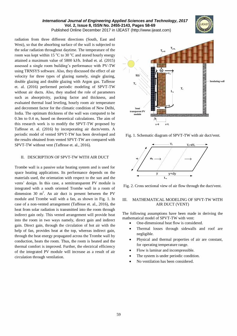
II. DESCRIPTION OF SPVT-TW WITH AIR DUCT
Trombe wall is a passive solar heating system and is used for
space heating applications. Its performance depends on the
materials used, the orientation with respect to the sun and the
vents’ design. In this case, a semitransparent PV module is
integrated with a south oriented Trombe wall in a room of
dimension 30 m2. An air duct is present between the PV
module and Trombe wall with a fan, as shown in Fig. 1. In
case of a non-vented arrangement (Taffesse et. al., 2016), the
heat from solar radiation is transmitted into the room through
indirect gain only. This vented arrangement will provide heat
into the room in two ways namely, direct gain and indirect
gain. Direct gain, through the circulation of hot air with the
help of fan, provides heat at the top, whereas indirect gain,
through the heat energy propagated across the Trombe wall by
conduction, heats the room. Thus, the room is heated and the
thermal comfort is improved. Further, the electrical efficiency
of the integrated PV module will increase as a result of air
circulation through ventilation.
Tr
Tx=0
Tx=L
I(t)
Ta
Lo
b
y=0
y=Lo
x=0 x=L
Insulating wall
Semi
transparent PV
module
Fig. 1. Schematic diagram of SPVT-TW with air duct/vent.
Fig. 2. Cross sectional view of air flow through the duct/vent.
III. MATHEMATICAL MODELING OF SPVT-TW WITH
AIR DUCT (VENT)
The following assumptions have been made in deriving the
mathematical model of SPVT-TW with vent:
One-dimensional heat flow is considered.
Thermal losses through sidewalls and roof are
negligible.
Physical and thermal properties of air are constant,
for operating temperature range.
Flow is laminar and incompressible.
The system is under periodic condition.
No ventilation has been considered.
Tf Tf+dTf
b
Lo
ṁf
y y+dy

International Journal of Engineering Applied Sciences and Technology, 2017 Vol. 2, Issue 8, ISSN No. 2455-2143, Pages 58-69 Published Online December 2017 in IJEAST (http://www.ijeast.com)
60
1
go
go
roco
tK
L
h
1
h
1U
1
gi
gi
rici
bK
L
h
1
h
1U
1
rc
ih
1
h
1h
Fig.3. Thermal circuit diagram of SPVT-TW with air
duct/vent
Based on these assumptions, the energy balance equations considering an elemental area,‘bdy’ (Fig. 2), for each
component of SPVT-TW with air duct/vent can be written
next. By considering Figs. 2 and 3, the energy balance
equations are:
For semitransparent PV module:
mmmfcbmactmcg βI(t)AηATTUATTUβI(t)Aατ
or
βI(t)ηTTUTTUβI(t)ατ mfcbactcg
(1)
where )T(Tβ1ητη ococogm
Substituting mη from above in Eq. (1), we get
c1tbfbateff I(t))TPF(UTUTUI(t))(α (2)
Where
ocog1bttboocogcgeff ββητPF andUUU,)Tββ(1ητβατ)(
m/s0V,3.8V5.7h,h
1
K
LU aao
1
og
g
t
,
and
m/s0v,3v2.8h,h
1
K
LU aai
1
ig
g
b
For Trombe wall at x=0 (Fig. 1):
m
0x
m0xfbfmbb
2
g Ax
Tk)AT(Thβ)I(t)A(1ατ
or
0x0xfbfbb
2
gx
Tk)T(Thβ)I(t)(1ατ
(3)
For Trombe wall at x=L (Fig. 1):
)TT(hx
Tk rLxi
Lx
(4)
For non-air conditioning room:
Energy balance equation for room air is as follows:
)T(TCm
Q)ATT(hdt
dTCM
rfff
iNrrLxir
aa
(5)
where iNQ is the heat gain through the upper vent/duct.
The energy balance equation for flowing fluid (air) in
dy)bTT(hdy)bT(TUdydy
dTcm f0xbffcb
fff
or
)bTT(h)bT(TUdy
dTcm f0xbffcb
fff
(6)
Now, I(t) and Ta can be expressed in terms of Fourier series,
due to periodic nature, as:
1n
inwtiψ
no eeIrealII(t) n (7a)
and,
1n
inwtiσ
anaoa eeTrealTT n (7b)
where nnanaono σand,ψ,T,T,I,I are Fourier coefficients
and are evaluated for known values of I(t) and Ta (Fig. 4).
Furthermore, since Ta and I(t) are periodic in nature, Tc, T, Tr
and Tf can be expressed as:
Ta
Tc
TfTx=0
Tx=L
Tr
1/hco 1/hro
Lgo/Kgo
Lgi/Kgi
1/h’ci 1/h’ri
Lw/Kw
1/hr1/hc
1/hbf
1/hi
Ut
Ub

International Journal of Engineering Applied Sciences and Technology, 2017 Vol. 2, Issue 8, ISSN No. 2455-2143, Pages 58-69 Published Online December 2017 in IJEAST (http://www.ijeast.com)
61
6
1n
inwt
cncoc eTrealTT (8)
inwt6
1n
xβ
n
xβ
n e)eDe(CrealBAxT nn
(9)
6
1n
inwt
rnror eTrealTT (10)
6n
1n
inwt
fnfof eTrealTT (11)
Substituting Eqs. ((7) - (11)) in Eqs.( (2) - (6)), we get
]eTreal]][TeeIreal[IPF[U]eTreal
[TU]eeTreal[TU]eeIreal[I)(α
6
1n
inwt
cnco
6
1n
inwtiψ
no1tb
inwt6
1n
fn
fob
6
1n
inwtiσ
anaot
6
1n
inwt-iψ-
noeff
n
nn
(12)
])eDβCβ(realK[A
])eD(CrealBeTreal[Th]eeIreal[I)(α
6
1n
inwt
nnnn
6
1n
6
1n
inwt
nn
inwt
fnfobf
6
1n
inwtiψ
noeffn
(13)
]eTrealT)eeDe(Creal
B[ALh])eeDβeCβ(realK[A
6
1n
6
1n
inwt
rnro
inwtLβ
n
Lβ
n
i
6
1n
inwtLβ
nn
Lβ
nn
nn
nn
(14)
]eTrealT-eTreal
[T]eTrealT)eeDe(Creal
B[ALhA]einwT[realCM
6
1n
inwt
rnro
6
1n
inwt
fn
fo
6
1n
6
1n
inwt
rnro
inwtLβ
n
Lβ
n
ir
6
1n
inwt
rnaa
nn
aacm
(15)
)beTrealT)eD(Creal(Bh)beTreal
TeTreal(TU]eTreal[m
6
1n
6
1n
inwt
fnfo
inwt
nnbf
6
1n
inwt
fn
fo
inwt6
1n
cncob
6
1n
inwt
fna
foa Tc
(16)
Next, we consider the Eqs. (12) - (16) for time-independent
portion and time-dependent portion separately.
Time-independent portion
The time-independent portion of Eqs. (12) - (16) are:
coo1cotbfobaoto TIPFTUTUTUI)( eff (17)
KAB)(ThI)ατ( fobfoeff (18)
]TB[ALhKA roi (19)
]T[Tc]TB[ALhA0 rofoaroir am (20)
)T(Bbh)T(TbUdy
dTcm fobffocob
foaa
(21)
Eq. (21) can be solved for Tfo and the average value of flowing
fluid (air) temperature using initial condition ro0xfo TT
as
follows:
]Lq
e1[T]
Lq
1[1
U
BhTUdxT
L
1T
ou
Lq
ro
ou
Lq
tT
bfcob
L
0
fo
o
fo
ououo
e
ro13
tT
bfcob
12fo Tg]U
BhTU[gT
(22)
where
ou
Lq
13
ou
Lq
12Lq
e1gand)
Lq
e1(1g
ouou
Substituting Eq. (22) in Eqs. ((17) - (20)), the time-
independent equations are simplified
aotoeffro13bco12
tT
2
b
o1tb12
tT
bfb TUI)(αTgU)TgU
UIPF(UBg
U
hU
(23)
KABh-TghBU
hgT
U
gUhI)ατ( bfro13bf
tT
2
bf12
co
tT
12bbf
oeff
(24)
]TB[ALhKA roi (25)
roaa13aairco
tT
baa
tT
12bfaa
irir )Tcmgcm-h(A-TU
Ucm)B
U
ghcmh(ALAhA0
(26)
Eqs. (23) - (26) can be arranged in a matrix form as:

International Journal of Engineering Applied Sciences and Technology, 2017 Vol. 2, Issue 8, ISSN No. 2455-2143, Pages 58-69 Published Online December 2017 in IJEAST (http://www.ijeast.com)
62
)cmgcmh(AU
ghcm
U
ghcmhALhA
h0hKLh
ghU
gUh
U
hghK
gUU
gUIPF-U
U
ghU0
aa13aair
tT
12bfaa
tT
12bfaa
irir
iii
13bf
tT
12bbf
tT
2
bf12
bf
13b
tT
12
2
b
o1tb
tT
12bfb
0
0
I)τ(
TU)(
T
T
B
A
oeff
aot
ro
co
oeff I
(27)
Time-dependent portion
Similarly, a matrix for time-dependent portion can be written
as:
inw)cMcm
gcmh(A0
U
ghcmehA
U
ghcmehA
h0)he(KβheKβ
ghU
Uhg)
U
ghh(Kβ
U
ghhKβ
gUU
gUeIPFIPFU
U
ghU
U
ghU
aaaa
13aair
tT
12bfaaLβ
ir
tT
12bfaaLβ
ir
ii
Lβ
ni
Lβ
n
13bf
tT
bbf12
tT
12
2
bf
bfn
tT
12
2
bf
bfn
13b
tT
12
2
biψ
n1o1tb
tT
12bfb
tT
12bfb
nn
nn
n
0
0
G
G
T
T
D
C
2
1
rn
cn
n
n
(28)
where
nnn iψ
nco1
iψ
ant
iψ
n1 eITPFeTUeI)(G
eff
niψ
neff2 eI)(αG
β)(1ατ)τ( bb
2
geff
coog1 ηββτPF
]Tβ[1βητβαττ)( oocogcgeff
Using matrices in Eqs. (27) and (28), all the unknown
constants for time-independent portion and time-dependent
portion can be evaluated. Subsequently, Tc, Tr, and Tf can be
obtained from Eqs. (8), (10) and (11), respectively.
Further, Lx0x
TandT
can be obtained as follows:
1n
inwt
nn0x)eD(CrealBT (29a)
inwt
1n
Lβ
n
Lβ
nLxe)eDe(CrealBALT nn
(29b)
IV. THERMAL LOAD LEVELING (TLL)
Since solar radiation and ambient air temperature are periodic
in nature, the room air temperature will fluctuate. Thermal
load leveling (TLL) is used as a measure to indicate this
fluctuation and is given as:
minrmaxr
minrmaxr
TT
TTTLL
(30)
V. DECREMENT FACTOR (F)
The reduction in amplitude of temperature at the inside surface
compared to the outside surface of the room is expressed by
decrement factor. It is given as (Ozel, 2013):
min0xmax0x
minLxmaxLx
)T()T(
)T()T(f
(31)
Fig. 4. Hourly variation of solar radiation, I(t), and ambient air
temperature, Ta.
VI. OVERALL EXERGY
The rate of thermal energy transferred from the Trombe at
LxT
and thermal energy arriving from upper vent is given
by:

International Journal of Engineering Applied Sciences and Technology, 2017 Vol. 2, Issue 8, ISSN No. 2455-2143, Pages 58-69 Published Online December 2017 in IJEAST (http://www.ijeast.com)
63
)TT(hQ rLxiuth
, and (32) (32)
)T(TcmQ rfoutffup (33)
Therefore, the total rate of thermal energy received by the
room is given by:
uputhth QQQ (34)
Further, an exergy of thermal energy can be evaluated as:
273T
273T273)ln(T)TT(hQ
r
LxarLxiuex
(35)
273T
273T273)ln(TTTcmQ
r
fout
arfoutffuex (36)
Electrical exergy, equivalent to electrical energy, can be
written as:
mmxel I(t)AηE (37)
Finally, overall exergy can be expressed as the sum of exergy
of thermal energy, given by Eqs. (35) - (36), and electrical
exergy, (Eq. 37). Overall exergy can be expressed as:
uexxelxov QEE (38)
VII. METHODOLOGY
The following methodology has been considered for analysis
of SPVT-TW with air duct/vent.
Hourly variation of solar intensity and ambient air
temperature, depicted in Fig, 4, and the design
parameters, specified in Table 1, have been used for
computations.
Fourier coefficients for Eqs. (6) and (7) are
determined. Subsequently, simulation is performed
using MATLAB 2013b software platform.
Time-independent constants (Tco, A, B, Tro, Tfo) (Eq.
(27)) and time-dependent constants (Tcn, Cn, Dn, Trn,
Tfn) (Eq. (29)) are computed using matrix inversion.
The known constants Tr, Tc, Tf, Lx0x
TandT
are computed.
Using the numerical value of Tc, PV module’s
temperature and electrical energy are evaluated using
Eqs. (1) and (37) respectively.
Eqs. (35)-(36) are used to evaluate the exergy of
thermal energy and overall exergy is computed using
Eq. (38).
VIII. RESULTS AND DISCUSSION
After mathematical modeling of the system, simulation is
developed using MATLAB 2013b software and the effect of
different parameters such as thickness of Trombe wall, absorptivity, packing factor, and transmittivity of PV module
on room air temperature and thermal comfort of the room is
evaluated.
Fig. 4 shows the hourly variation of solar intensity and
ambient air temperature as measured on January 21st, for New
Delhi, India. Fig. 5a depicts the room air temperature,
temperature distribution at x=0 (outer surface of Trombe wall,
painted black) and temperature distribution at x=L (i.e. inner
surface of Trombe wall) for different thickness of Trombe
wall, for vented SPVT-TW.
It can be seen that the fluctuation in room air temperature
decreases with an increase in thickness of Trombe wall, and it
maintains at around 45 oC. Fig. 5b compares the hourly
variation of room air temperature of vented SPVT-TW with
SPVTW without vent (Taffesse et. al., 2016) for different
Trombe wall thicknesses. It can be seen from Fig. 5b that the
room air temperature for vented SPVT-TW is higher than for
SPVT-TW without vent. Also, the vented SPVT-TW gives
better thermal stability in room, with less thickness of Trombe
wall, than the SPVT-TW without vent. Further, it can be
observed that for higher thickness of Trombe wall, room air
temperature and Lx
T
are the same for vented SPVT-TW
(Fig. 5a), as expected.
Fig. 6 demonstrates the comparison between thermal load
leveling for the SPVT-TW with and without vent. The SPVT-TW with vent achieves better thermal stability or less
fluctuation in room air temperature than the SPVT-TW
without vent (Taffesse et. al., 2016). The vented SPVT-TW
provides better thermal comfort with small thickness of
Trombe wall as compared to the SPVT-TW without vent. The
optimum thickness of Trombe wall, which offers higher
stability of room air temperature for vented and unvented
SPVT-TW, is 0.3 m and 0.4 m respectively.
Fig. 7 illustrates the effect of mass flow rate on cell
temperature (a) and electrical efficiency of PV module (b). It
can be seen that the solar cell temperature increases as the mass flow rate decreases and hence, the electrical efficiency
decreases as expected. However, the room air temperature will
decrease with a decrease in mass flow rate.

International Journal of Engineering Applied Sciences and Technology, 2017 Vol. 2, Issue 8, ISSN No. 2455-2143, Pages 58-69 Published Online December 2017 in IJEAST (http://www.ijeast.com)
64
For L=0.2 m
For L=0.25 m
For L=0.3 m For L=0.35 m
For L=0.4 m
For L=0.45 m
Fig. 5a. Hourly temperature distribution for Trombe wall at Tx=0 , Tx=L and room air temperature, Tr.

International Journal of Engineering Applied Sciences and Technology, 2017 Vol. 2, Issue 8, ISSN No. 2455-2143, Pages 58-69 Published Online December 2017 in IJEAST (http://www.ijeast.com)
65
For L=0.2 m
For L=0.25 m
For L=0.4 m
For L=0.45 m
Fig. 5b. Hourly room air temperature distribution for different thicknesses of Trombe wall in SPVT-TW with and without air vent.

International Journal of Engineering Applied Sciences and Technology, 2017 Vol. 2, Issue 8, ISSN No. 2455-2143, Pages 58-69 Published Online December 2017 in IJEAST (http://www.ijeast.com)
66
Fig. 6. Variation of thermal load leveling with thickness of
Trombe wall.
(a)
(b) Fig. 7. Hourly variation of (a) cell temperature with mass flow
rate and (b) efficiency of PV module with mass flow rate
Fig. 8. Variation of thermal load leveling and decrement
factor with absorptivity of PV module.
Fig. 8 illustrates the variation in absorptivity of PV module
with thermal load leveling and decrement factor. As can be
seen, with an increase in absorptivity of PV module, there is
a decrease in thermal load leveling and consequently, a
better thermal stability is achieved inside the room. From
thermal point of view, the optimum value of TLL is
obtained as 0.0037 for absorptivity 0.9.
Fig. 9. Variation of thermal load leveling and decrement
factor with packing factor of PV module.
Fig. 9 depicts the effect of packing factor of the PV module
on thermal load leveling and decrement factor. As the
packing factor increases, a better thermal load leveling, as

International Journal of Engineering Applied Sciences and Technology, 2017 Vol. 2, Issue 8, ISSN No. 2455-2143, Pages 58-69 Published Online December 2017 in IJEAST (http://www.ijeast.com)
67
well as decrement factor, are attained. The optimum value
of TLL is obtained as 0.0038 for a packing factor of 0.9.
Therefore, for a better thermal stability in the room, a higher
packing factor is preferable.
Fig. 10. Variation of thermal load leveling and decrement
factor with mass flow rate of air.
Fig. 11. Variation of thermal load leveling and decrement
factor with transmittivity of PV module.
Fig. 10 illustrates the effect of mass flow rate on the thermal
stability of the room. It can be seen that for a better room air
temperature stability, the mass flow rate should be high.
Hence, by controlling the mass flow rate of air we can
provide a better thermal comfort to the room. By
considering the cost and size of the fan, the optimum value of mass flow rate should be 0.06 Kg/s, for which TLL is
0.0017.
The effect of transmittivity on thermal stability inside a
room is shown in Fig. 11. As can be seen, an increase in
transmittivity causes the thermal load leveling to increase.
From a thermal comfort point of view, the thermal load
leveling should be as low as possible and this can be
achieved by considering a low value of transmittivity.
Therefore, the optimum value of transmittivity is 0.4, for
which thermal load leveling is 0.000208.
The variation of an exergy of thermal energy, electrical
energy, and an overall exergy are given in Fig. 12. As shown, the rate of thermal exergy is much lower than
electrical output, as expected. This indicates that the vented
SPVT-TW can provide electrical power in addition to the
thermal needs of a building.
Fig. 12. Hourly variation of rate of thermal exergy,
electrical output and an overall exergy.
IX. CONCLUSIONS
The effect of thickness of Trombe wall on room air
temperature has been analyzed and consequently,
the optimum thickness of Trombe wall for vented
SPVT-TW is obtained to be 0.3 m for comfortable room air condition.
The mass flow rate of air has a noteworthy
influence on room temperature as well as thermal
stability within the room. In order to achieve a
better thermal stability in the room, the mass flow
rate should be 0.06 Kg/s and the corresponding
thermal load leveling is 0.0017.
Vented SPVT-TW can provide more heat energy to
the room and thus, the room air temperature is

International Journal of Engineering Applied Sciences and Technology, 2017 Vol. 2, Issue 8, ISSN No. 2455-2143, Pages 58-69 Published Online December 2017 in IJEAST (http://www.ijeast.com)
68
higher for vented SPVT-TW than for SPVT-TW without vent. (Taffesse et. al., 2016), with the
difference being around 10-12 oC.
The design parameters like packing factor,
transmittivity and absorptivity of PV module have
a significant effect on thermal stability inside the
room. From the analysis, the ideal values of
transmittivity, absorptivity and packing factor are
obtained as 0.4, 0.9 and 0.9 respectively, with the
corresponding thermal load leveling of 0.0038,
0.000208 and 0.0037 respectively.
X. RECOMMENDATIONS
Experimental validation should be carried out for
the proposed thermal model for different climatic
conditions.
The proposed model could be extended for thermal
cooling for hot climatic conditions.
Table. 1. Various design and specification parameters used
for SPVT-TW with air duct/vent.
Table 2. Nomenclature
Design Parameters
)h (rad24
2πw 1
)s (rad3600*24
2πw 1
o
K)(KJ/Kg0.84c
)(Kg/m1600ρ 3
0.9τg
m0.003Lg
W/m0.6Kg
K) (W/m0.69K
K)(W/m2.8h 2
i
K)(W/m5.54h 2
o
2
r m30A
0.12ηco
2
m m20A
Kg147Ma
)KKg(KJ1.005C -1-1
a
)(W/m5.54u 2
t
)(W/m2.8u 2
b
0.9αc
0.9αbb
0.9β
)(K0.0045β 1
o
m0.15b
m3Lo
0.12ηco
K)(W/m18h 2
bf
Am PV module’s area (m2)
Ar area of single room (m2)
Ca specific heat of air (J/Kg 0C)
Ma mass of air (Kg)
ḿf mass flow rate of air (Kg/s)
b gap between the PV module and
Trombe wall (m)
L thickness of Trombe wall (m)
Lo height of Trombe wall (m)
I(t) solar radiation (W/m2)
K thermal conductivity (W/m K)
Lg thickness of glass (m)
Kg thermal conductivity of glass (W/m K)
n number of harmonics
ho outside heat transfer coefficient
(W/m2 K)
hi convective and radiative heat
transfer coefficient from internal
surface of Trombe wall to room
(W/m2 K)
hbf convective heat transfer
coefficient from blackened
surface of Trombe wall to air
inside the duct (W/m2K)
Ta ambient temperature (oC)
Tc solar cell temperature (oC)
Tr room air temperature (oC)
Va speed of air (m/s)
Ut overall heat transfer coefficient
from solar cell to ambient
through
glass cover (W/m2 K)
Ub overall heat transfer coefficient
from solar cell to blackened
surface of Trombe wall through
glass cover (W/m2 K)
Greek symbols
αc absorptivity of solar cell
αbb absorptivity of blackened
surface of Trombe wall.
β packing factor of PV module
βo temperature coefficient (K-1)
ηm efficiency of PV module
ρ density of concrete (stone) (Kg/m3)
gτ transmittivity of glass
ηco efficiency of PV cell at standard
test condition
subscripts
m module, t top, r room, a air
c solar cell, g glass, b bottom
bb blackened

International Journal of Engineering Applied Sciences and Technology, 2017 Vol. 2, Issue 8, ISSN No. 2455-2143, Pages 58-69 Published Online December 2017 in IJEAST (http://www.ijeast.com)
69
XI. REFERENCES
[1] Gan, G., 1998. A parametric study of Trombe walls for
passive cooling of buildings. Energy and building 27,
37-43.
[2] Irshad, K., Habib, K., Thirumalaiswamy, N., 2015.
Performance Evaluation of PV-Trombe Wall for Sustainable Building Development. 12th Global
conference on sustainable manufacturing procedia CIRP.
26, 624-629.
[3] Jiang, B., Jie, J., Hua, Y., 2008. The influence of PV
coverage ratio on thermal and electrical performance of
photovoltaic-Trombe wall. Renewable energy 33, 2491-
2498.
[4] Jie, J., Hua, Y., Wei, H., Gang, P., Jianping, L., Bin, J.,
2007. Modeling of a novel Trombe wall with PV cells.
Building and Environment 42, 1544-1552.
[5] Koyunbaba, B.K., Yilmaz, Z., 2012. The comparison of Trombe wall systems with single glass, double glass and
PV
panels. Renewable Energy 45, 111-118.
[6] Mansour A.R., Jubran, B.A., Tashtoush, B., 1991. An
approximate analytical solution to convective laminar
heat transfer flow within the trombe wall channel.
International Communications in Heat and Mass Transfer
18,153-159.
[7] Ozel, M., 2013. Determination of optimum insulation
thickness based on cooling transmission load for
building walls in a hot climate. Energy Conversion
Management 66, 106-114. [8] Rabani, M., Kalantar, V., Dehghan, A.A., Faghih, A.K.,
2015. Experimental study of the heating performance of
a Trombe wall with a new design. Solar Energy 118,
359-374.
[9] Smolec, W., Thomas, A., 1991. Some aspects of trombe
wall heat transfer models. Energy Conversion
Management 32, 269-277.
[10] Taffesse, F., Verma, A., Singh, S., Tiwari, G.N., 2016.
Periodic modeling of the semi-transparent photovoltaic
thermal-Trombe wall (SPVT-TW). Solar Energy 135,
265-273.