PUBLIC WORKS TECHNIC AL BULLETIN 200-1-118 30 APRIL 2012 · PUBLIC WORKS TECHNIC AL BULLETIN...
187
PUBLIC WORKS TECHNICAL BULLETIN 200-1-118 30 APRIL 2012 IMPLEMENTING SUSTAINABLE WATER MANAGEMENT STRATEGIES IN HISTORIC DISTRICTS
Transcript of PUBLIC WORKS TECHNIC AL BULLETIN 200-1-118 30 APRIL 2012 · PUBLIC WORKS TECHNIC AL BULLETIN...

PUBLIC WORKS TECHNICAL BULLETIN 200-1-118 30 APRIL 2012
IMPLEMENTING SUSTAINABLE WATER MANAGEMENT STRATEGIES
IN HISTORIC DISTRICTS

Public Works Technical Bulletins are published by the US Army Corps of Engineers, Washington, DC. They are intended to provide information on specific topics in areas of Facilities Engi-neering and Public Works. They are not intended to establish new Department of the Army (DA) policy.

DEPARTMENT OF THE ARMY US Army Corps of Engineers
441 G Street NW Washington, DC 20314-1000
CECW-CE
Public Works Technical Bulletin 30 April 2012
No. 200-1-118
Facilities Engineering Environmental
IMPLEMENTING SUSTAINABLE WATER MANAGEMENT STRATEGIES IN HISTORIC DISTRICTS
1. Purpose.
a. This Public Works Technical Bulletin (PWTB) supports the sustainable stormwater management goals within the Department of Defense (DoD). This PWTB presents a brief history of water man-agement systems, a review of policies and regulations affecting stormwater management and cultural resource preservation, and an evaluation of sustainable methods appropriate for incorporation into historic districts.
b. All PWTBs are available electronically at the National Institute of Building Sciences’ Whole Building Design Guide webpage, which is accessible through this link:
http://www.wbdg.org/ccb/browse_cat.php?o=31&c=215
2. Applicability. This PWTB applies engineering activities by resource and land managers at all US Army facilities in the United States.
3. References.
a. National Historic Preservation Act (NHPA) of 1966.
b. National Environmental Policy Act (NEPA) of 1969, Public Law 91-190, January 1, 1970, as amended.

PWTB 200-1-118 30 April 2012
2
c. Army Regulation (AR) 200-1, "Environmental Protection and Enhancement," 13 December 2007.
d. Unified Facilities Criteria (UFC) 3-210-10, “Design: Low Impact Development Manual,” 15 November 2010 (updated from 2004).
e. Memorandum on “Sustainable Design and Development Policy Update – SpiRiT to LEED Transition,” Office of the Assistant Secretary of the Army, Installations and Environment, 5 January 2006.
f. Executive Order (EO) 13514, “Federal Leadership in Envi-ronmental, Energy and Economic Performance,” 5 October 2009.
4. Discussion
a. Incorporating sustainable water management systems into historic districts can provide many benefits; however, all new undertakings have to comply with the requirements of the NHPA. The NHPA, as amended, requires federal agencies to consider the historic importance of properties under their administration. Preserving historic properties conveys the nation’s heritage through increased knowledge of historic resources. This require-ment includes establishing better means of identifying and ad-ministering federal properties to maintain their cultural, educational, aesthetic, and economic benefits. The NHPA estab-lished the National Register of Historic Places (NRHP) and Na-tional Historic Landmarks (NHL) on which qualifying properties can be listed. State Historic Preservation Offices (SHPOs) and federal agencies are tasked to work together for identifying, nominating, and maintaining the historic characteristics of eligible properties.
Significant in NHPA are the actions outlined in Sections 106 and 110. Section 106 requires federal agencies to consider the ef-fects of undertakings on historic properties while also giving the Advisory Council on Historic Preservation an opportunity to comment on proposed actions. This review process includes all stakeholders, to determine if actions could potentially affect historic properties. The process includes identifying historic properties, assessing potentially adverse effects, resolving adverse effects, and implementing the terms of the agreement. Section 110 expands and makes explicit a federal agency’s re-sponsibility for identifying and protecting historic properties.
To satisfy this review process, each federal agency must estab-lish a preservation program to identify, evaluate, nominate, and

PWTB 200-1-118 30 April 2012
3
protect historic properties under their administration. Agency planning is required to consider the historic, archaeological, architectural, and cultural values conveyed by historic proper-ties. If an agency has a historic property, effort must be made to adaptively reuse the property before new construction is considered. Section 110 is also important because it establishes the criteria for integrating preservation planning into all federal agency programs (NHPA, as amended, 2006).
b. NEPA unifies environmental decision-making processes across federal agencies. This requires agencies to consider environmental consequences related to land use, air and water quality, wildlife and habitat, socioeconomic factors, human health and safety, as well as natural and historical resources. The policy contains an “action-forcing” provision to compel agencies to document their efforts to comply with the policy set forth in the law.” Agencies are directed to use a “systematic, interdisciplinary approach” ensuring the integration of natural and social sciences and environmental design arts into planning and decision-making. As a result, federal agencies are required to conduct environmental assessments (EA) and environmental impact statements (EIS) to make informed environmental decisions when considering and planning new projects, which includes ret-rofitting existing facilities.
c. AR 200-1 outlines environmental policies and designates program requirements in order to comply with federal policies. Chapter Four, Section 2 outlines the policy for water resource management and especially, Section E entitled “Stormwater Man-agement.” This section pertains to policy controlling or elimi-nating sources of pollution to prevent contamination of water bodies or ground water. A second policy uses abatement measures for nonpoint source runoff from facilities, construction, and land management activities. Program requirements include obtain-ing specified permits, providing stormwater management plans, and providing stormwater pollution prevention plans.
d. The 2004 release of UFC 3-210-10 provided general policy regarding retrofitting buildings within the DoD. The document noted that “older DoD facilities were developed either with traditional approaches or with no stormwater management at all.”
Eventually, stormwater management components will have to be installed, replaced, or retrofitted – a costly task. DoD will inevitably need to replace pipes and dredge stormwater ponds. The guidance in UFC 3-210-10 directly pertains to this PWTB because it bridges a gap between older facilities that were not

PWTB 200-1-118 30 April 2012
4
built to modern standards but are up for retrofitting, which necessitates the integration of historic properties with newer stormwater management plans and technologies that adhere to current regulation and policy. The 2010 release of UFC 3-210-10 acknowledges building retrofit issues and references sustaina-bility and architectural compatibility for DoD facilities.
UFC 3-210-10 also requires agencies to seek advice, participa-tion, and comments from appropriate governmental agencies and stakeholders and to inform interested public and private organi-zations of their activities.
e. The Leadership in Energy and Environmental Design (LEED) Green Building Rating System is an internationally recognized building certification system to provide third-party verifica-tion that any building, development, or community was designed and built utilizing sustainable practices. The system is points-based, with points awarded relative to the sustainability of the building practice used within the project. Projects may earn a LEED certification of “Certified,” “Silver,” “Gold,” or “Plati-num” relative to the number of green technologies and practices that qualify under the certification system. The DoD encourages agencies to use the LEED checklist and apply for certification. Within the Army, the Sustainable Project Rating Tool was previ-ously used; however, it has been replaced with the LEED system as a guiding principle for development (OASA[I&E] 2006).
f. Goal 2 of EO 13514 established targets to improve water resources management and the reduction of stormwater runoff.
g. This PWTB evaluates the potential of integrating Green Infrastructure (GI), Low Impact Development (LID), and Light Imprint (LI) water management strategies and technologies in historic districts on US Army installations. Incorporating sus-tainable water management systems into historic districts can provide many benefits; however, all new undertakings have to comply with the requirements of the NHPA. Guidance is provided in this PWTB for the selection of historically compatible sus-tainable water management systems. Application of the infor-mation presented in this bulletin will provide installation personnel with basic information on integrating sustainable stormwater management techniques into historic districts.
h. Appendix A of this PWTB provides a table of contents and list of figures and tables.
i. Appendix B contains an introduction to traditional storm-water management systems. This section outlines the historical

PWTB 200-1-118 30 April 2012
5
development of such systems, presents a stormwater management case study, and outlines general management goals and objec-tives. The appendix also briefly summarizes the process of tra-ditional stormwater management system design and the cost benefits of those systems.
j. Appendix C contains current regulatory and legislative policy supporting the implementation of sustainable systems on Army installations as well as cultural resource management re-quirements and guidance.
k. Appendix D contains guidance on how to develop a sustain-able infrastructure implementation strategy for historic dis-tricts. Although sustainability is the foundation of the Army’s environmental strategy, historic districts on military installa-tions present challenges for installation-wide deployment of sustainable technologies. Sustainable infrastructure naturally has different aesthetics than those originally implemented in historic districts; as a result, the historic feeling of the district is potentially compromised. This section outlines steps in navigating cultural resource legislative requirements for districts when new undertakings are proposed.
l. Appendix E contains an overview of green and sustainable infrastructure, management techniques, and potential implementa-tion processes.
m. Appendix F contains adaptation strategies for historic districts. This section proposes possible small- to large-scale deployments of sustainable stormwater management strategies such as material choices, vegetation options, and landform modifica-tions. This section also includes case studies of sustainable stormwater projects recently completed or in-process at several Army installations in different ecological zones throughout the United States.
n. Appendix G shows a matrix diagram of GI technologies and their appropriateness for incorporation in historic districts.
o. Appendix H is a catalog of sustainable technologies with images of completed projects and general information about each technology’s features.
p. Appendix I contains studies of successful implementation of GI outside of military installation historic districts.

PWTB 200-1-118 30 April 2012
6
q. Appendix J concludes with final lessons learned, sugges-tions for best management practices, and recommendations. The conclusions given in Appendix J are summarized below.
• Care should be taken to understand a historic landscape’s character-defining features and retain those aspects in any new undertaking.
• Communicate with all stakeholders during any stormwater planning process and for effective project integration.
• Keep LID practices small and site-specific to ensure proper functioning and to avoid adverse effects.
• Maintenance of installed systems is relatively inexpen-sive and essential to proper function.
• Cost savings can be substantial when a sustainable water management strategies are used within a historic dis-trict.
r. Other useful information is contained in the final three appendices: Appendix K contains references, Appendix L lists the people interviewed for this project, and Appendix L gives mean-ings for abbreviations used throughout this document.
5. Points of Contact.
a. Headquarters, US Army Corps of Engineers (HQUSACE) is the proponent for this document. The point of contact (POC) at HQUSACE is Mr. Malcolm E. McLeod, CEMP-CEP, 202-761-5696, or e-mail: [email protected].
b. Questions and/or comments regarding this subject should be directed to the technical POC:
US Army Engineer Research and Development Center (ERDC) Construction Engineering Research Laboratory (CERL) ATTN: CEERD-CN-N Anne Dain-Owens CEERD-CN-C Ellen Hartman PO Box 92902 Newmark Drive Champaign, IL 61822-1076 Tel. (217) 373-6511 FAX: (217) 373-7266 e-mail: [email protected] [email protected]


PWTB 200-1-118 30 April 2012
A-1
APPENDIX A
TABLE OF CONTENTS
Appendix A TABLE OF CONTENTS A-1
Appendix B TRADITIONAL STORMWATER MANAGEMENT SYSTEMS B-1
Introduction B-1
Development of Traditional Stormwater Management Systems B-3
Conventional Stormwater Management Case Study B-4
Stormwater Management Goals, Objectives, and General Technologies B-7
Design Process B-8
Cost-Benefit or Return on Investment B-10
Sustainability as an Issue in Stormwater Management B-14
Appendix C CURRENT REGULATIONS AND LEGISLATION C-1
Preservation of Historic Properties C-1
Environmental Legislation Relating to Stormwater Management C-2
Clean Water Act C-2
Coastal Zone Management Act of 1972 C-4
Safe Drinking Water Act of 1974 with the 1986 Wellhead Protection Program Amendment C-5
Energy Policy Act of 1992 C-5
Department of the Navy “LID Policy,” 16 November 2007 C-5
Energy Independence and Security Act of 2007 C-5
Army Regulation 200-1 C-6

PWTB 200-1-118 30 April 2012
A-2
Executive Order 13148, Greening the Government through Leadership in Environmental Management, 2000 C-6
Executive Order 13423, Strengthening Federal Environmental, Energy, and Transportation Management, 2007 C-7
Executive Order 13514, Federal Leadership in Environmental, Energy, and Economic Performance, 2009 C-7
Memorandum for Sustainable Design and Development Policy Update (Environmental and Energy Performance, Revision, 2010) C-7
Net Zero Army Initiative C-8
Leadership in Energy and Environmental Design Green Building Rating System C-8
Unified Facilities Criteria C-8
Other Voluntary Programs and Agreements C-9
DoD Retrofit Policy C-9
Appendix D UNDERSTANDING THE HISTORIC DISTRICT D-1
Establishing Historic Context D-1
Developing a Natural Systems Historic Context D-3
Evaluating the Existing Stormwater Management System D-4
Navigating Preservation and Sustainability Issues D-5
Appendix E GREEN INFRASTRUCTURE E-1
Green Infrastructure Strategies E-2
Low Impact Development E-2
Light Imprint E-3
Environmental Benefits E-4
Costs and Benefits E-7
Implementation Process E-11
PWTB 200-1-118 30 April 2012
A-3
Appendix F ADAPTING HISTORIC DISTRICTS F-1
Fort Leavenworth, Kansas F-1
Fort Huachuca, Arizona F-2
Joint Base Lewis-McChord, Washington F-4
Fort Knox, Kentucky F-5
Appendix G MATRIX OF GREEN INFRASTRUCTURE TECHNOLOGIES AND HISTORIC DISTRICT COMPATIBILITY G-1
Appendix H CATALOG OF GREEN INFRASTRUCTURE TECHNOLOGIES H-1
Concrete pipe H-2
Drainage ditch H-3
Dry well H-4
Foundation or Side-of-Building Plantings H-5
Vertical Plantings (Greenwalls) H-6
Natural Creek H-7
Natural Vegetation H-9
Soakaway Trench H-10
Stone / Riprap Channel H-11
Surface Landscaping H-13
Corrugated Metal – Vault/Cistern H-14
Plastic Vault/Cistern H-15
Precast Concrete – Vault/Cistern H-17
Brick Pavers H-18
Cobblestone Pavers H-19
French Drain H-20
Gutter/Curb H-22
Integrated Tree Grove and Parking Area H-24

PWTB 200-1-118 30 April 2012
A-4
Masonry Trough H-25
Natural Stone Pavers H-27
Turf Block (Grassed Cellular Concrete) H-28
Pool/Fountain/Paved Basin H-29
Sheetflow to Riparian Buffers or Filter Strips H-30
Swale Systems with Curbs and Curb Cuts H-31
Grated Tree Well H-32
Asphalt Paving Blocks H-34
Cast-In-Place / Pressed-Block Concrete Pavement H-35
Pervious Asphalt H-37
Pervious Concrete H-38
Grassed Cellular Plastic H-39
Bioengineering H-40
Disconnected Impervious Surfaces H-42
Green Finger H-43
Geomat H-44
Porous Pavement Underground Recharge Bed H-45
Rain Garden H-46
Retention Hollow H-47
Stormwater Planter H-48
Stream Daylighting H-49
Terracing H-50
Vegetative / Stone Swale H-51
Bioretention Swale H-53
Vegetative Purification Bed H-55

PWTB 200-1-118 30 April 2012
A-5
Wetland/Shallow Marsh/Swamp H-56
Detention Pond H-57
Roof Garden / Green Roof H-58
Canal H-59
Compacted Earth H-60
Crushed Stone / Gravel / Shell H-61
Vegetation Islands / Planting Strip Trenches H-62
Pea Gravel H-64
Wood Paving Blocks H-65
Wooden Planks H-66
Constructed Wetland H-68
Retention Pond H-70
Flowing Waterscapes H-72
Purification Biotope H-74
Slope Avenue H-75
Appendix I SUCCESSFUL IMPLEMENTATIONS OF SUSTAINABLE TECHNOLOGIES I-1
Greece I-1
Sinagua in Northern Arizona I-3
Jackson Barracks, Louisiana I-4
Current Applications of Green Infrastructure I-6
Portland, Oregon I-6
Chicago, Illinois I-7
Appendix J LESSONS LEARNED AND CONCLUSIONS J-1
Lessons Learned J-1
Conclusions J-2
PWTB 200-1-118 30 April 2012
A-6
Appendix K REFERENCES K-1
Appendix L INTERVIEW LIST L-1
Appendix M ACRONYMS and ABBREVIATIONS M-1
LIST OF FIGURES
Figure B-1. Typical systems diagram of the natural hydrological process unaffected by anthropogenic development or other impacts. ................................................. B-1
Figure B-2. Typical systems diagram of hydrologic processes affected by urban development. ........................... B-2
Figure B-3. Large-scale view of a hydrologic cycle for developed land (UFC 3-210-10, as presented in McCuen 1998.) ........ B-2
Figure B-4. Relationships between monetary loss, storm intensity, and storm frequency (Debo and Reese 2003). .. B-13
Figure E-1. Chart showing the relative cost of stormwater management systems relative to the distance of water source (BASMAA 1997). ........................................... E-9
Figure E-2. Sustainable stormwater systems decision chart (diagram created by synthesizing information from Low Impact Development Center 2004; Fuss and O’Niell 2010; and UFC 3-210-10, 2010; WERF 2009a, 2009b, and 2007a were also used within this process). ................................... E-12
Figure E-3. Classifications of hydrologic soil groups (US Soil Conservation Service 1987). ............................. E-14
Figure E-4. Decision process chart for IMPs to maintain predevelopment runoff volume and peak runoff rate. CN is the runoff curve number; Tc is the time of concentration (Prince George’s County 1999). .................................. E-15
Figure F-1. Aerial view of Fort Huachuca, 1924 (Fort Huachuca Cultural Resources). ..................................... F-3
Figure F-2. Aerial view of Fort Huachuca historic district, 1980s (Fort Huachuca Cultural Resources). ................ F-4
Figure H-1. Subsurface concrete pipe installation (Portland Cement Association 2011). ................................ H-2

PWTB 200-1-118 30 April 2012
A-7
Figure H-2. Drainage ditch in an agricultural field near Ruthsburg, Maryland (Wicks 2008). ........................ H-3
Figure H-3. Diagram of a simple dry-well design (Tanski n.d., as presented in Schueler 1987). .......................... H-4
Figure H-4. Foundation plantings at a residence, 10 years after installation (Parker Landscape and Drainage n.d.) ........ H-5
Figure H-5. Marché des Halles in Avignon (TheGrowSpot.com 2007). ......................................................... H-6
Figure H-6. Looking along Trappe Creek towards Newport Bay (Thomas 2006b). .......................................... H-7
Figure H-7. Tryon Creek, rehabilitated to carry stormwater through a development; seasonal use so only wet during rainy periods or wet seasons (USEPA 2008f). .................... H-8
Figure H-8. Native garden in Amos Garrett Park (Thomas 2007). H-9
Figure H-9. Vegetated soakaway trench (Natural Environment Research Council 2011). ................................. H-10
Figure H-10. Schematic design of a soakaway system (Natural Environment Research Council 2011). ..................... H-10
Figure H-11. Natural landscaping utilizing riprap for channel protection, aiding infiltration and protecting against erosion (Landscape Drainage Solutions Inc. 2003). ...... H-11
Figure H-12. Diagrams of variations in shape and design of riprap channels for hydraulic flow (UNEP 1994). ......... H-12
Figure H-13. Riprap swale in natural setting (Roberts 2009). H-12
Figure H-14. Backyard area with surface landscaping (all groundcovers or shrubs and trees; the ‘lawn’ area is a low groundcover (Harris, 2007) .............................. H-13
Figure H-15. Another area previously grassed, now under conversion into a surface landscape of low-lying groundcovers (Harris, 2007). ......................................... H-13
Figure H-16. Stormwater detention / infiltration system utilizing corrugated metal (Contech Construction Inc. 2011). ........................................................ H-14

PWTB 200-1-118 30 April 2012
A-8
Figure H-17. Metal cisterns can also be installed above ground, either round (not shown) or in slimline dimensions in order to be less invasive (Tanks Alot n.d.) ................... H-14
Figure H-18. Example diagram of an underground plastic cistern shown, as would be connected to a house rainwater and greywater system (GRAF 2011). ........................... H-15
Figure H-19. Subterranean plastic cistern (The Rain Well n.d.). ........................................................ H-16
Figure H-20. Above-ground rain tank on the side of a residence (RainBarrelSource.com 2011). ............................ H-16
Figure H-21. Cisterns in basement of Friends Center (EPA 2009a). ........................................................ H-16
Figure H-22. Precast concrete cistern during installation (American Concrete Industries n.d). ..................... H-17
Figure H-23. Walkway made with brick pavers (Décor Guide 2011). ........................................................ H-18
Figure H-24. Cobble stone road (Monarch Stone International 2009). .................................................. H-19
Figure H-25. French drain on a golf course (Golfmak Inc. n.d.). ........................................................ H-20
Figure H-26. French drain diagram illustrating integration drainage with another LID technology (swale) (Golftmak, Inc. n.d.). .................................................. H-21
Figure H-27. Typical curb and gutter system showing stormwater outlet into local water body (State of Delaware n.d). ... H-22
Figure H-28. Creative bioretention facility as an extension of the curbed area alongside a street (EPA 2008e). ......... H-23
Figure H-29. A sculpted gutter feature along a walkway to convey stormwater (EPA 2008g). ................................. H-23
Figure H-30. Valley gutter in the alleyway of high-density residential development (EPA 2007c). .................... H-23
Figure H-31. Tree grove integrated into paved area creates a pervious surface parking lot without curbs (Novak 2008). H-24

PWTB 200-1-118 30 April 2012
A-9
Figure H-32. Masonry trough, Freiburg, Germany; a thirteenth-century stormwater channel system forms part of the Dreisam river (Lisa Town 2009). ................................. H-25
Figure H-33. Smaller-scale masonry trough utilized in conjunction with urban tree plantings in Grenada, Spain (Low 2008). .................................................. H-26
Figure H-34. Sandstone pavers used for the walkways (GroundTradesXchange 2008). ............................. H-27
Figure H-35. Turf block used in an entryway drive and parking lot (Alpine Limited n.d.). ............................. H-28
Figure H-36. Trench drain along this fountain captures stormwater and fountain overflow to be reused in the civic water feature (Novak 2008). ............................. H-29
Figure H-37. Vegetated swale runs the length of the street (EPA, 2008k). ................................................. H-30
Figure H-38. Curb cut from paved area, allowing water to run off into vegetated areas (EPA 2008a). ................... H-31
Figure H-39. Grated tree well in an urban area (KK Manhole & Gratings Co. Pvt. Ltd n.d.). ............................ H-32
Figure H-40. Diagram of Grated tree well utilized for stormwater management (Charles River Watershed Association 2009). .. H-33
Figure H-41. Various examples of asphalt block used as pavers (Top Asphalt Limited n.d.). ............................. H-34
Figure H-42. Cast-in-place concrete, stamped with the block pattern, then colored and finished to achieve desired look (Professional Concrete 2010). ........................... H-35
Figure H-43. Cast-in place concrete, stamped with a brick pattern and dyed red (Professional Concrete 2010). ...... H-36
Figure H-44. Concrete pavers utilized in a walkway area (Walsh 2011). .................................................. H-36
Figure H-45. Presentation of how well the porous asphalt allows water to percolate through the pavement (City of Sturgis 2011). .................................................. H-37

PWTB 200-1-118 30 April 2012
A-10
Figure H-46. Example of porous concrete water flow (VDC Green 2010). .................................................. H-38
Figure H-47. One example of cellular plastic that shows the stages of installation with some cells empty, some filled with gravel growing media, and some fully grown-in with grass (Boddingtons 2011). ..................................... H-39
Figure H-48. Watercourse restoration utilizing bioengineering (Bioengineering Group, Inc., University of Iowa Stormwater & Bioengineering Design n.d.). ............................ H-40
Figure H-49. Example diagram of a swale and watercourse bank stabilized with vegetation utilizing bioengineering techniques (Bioengineering Group, Inc., Upper Connecticut River Habitat Restoration Plan, NH, n.d.). .............. H-41
Figure H-50. Example diagram of a swale showing the use of bioengineering techniques (Bioengineering Group, Inc. n.d.). ........................................................ H-41
H-51. Examples of how impervious surfaces can be separated from each other with sections of pervious pavement, vegetated areas, and a drain between the sidewalk and the street (EPA 2008i). ................................................. H-42
H-52. In Boston, Green Finger catchment areas extend into the urban fabric (Landscape Communications, Inc. 2010). ..... H-43
H-53. Newly installed turf reinforcement mat (green) with scour stop mat (white) (Scourstop 2008). ...................... H-44
Figure H-54. Diagram of a typical recharge bed under a porous parking lot (Adams, 2003). .............................. H-45
Figure H-55. A rain garden with an underdrain (see outlet in gravel just above garden berm left of center; Wilson 2009). .. H-46
Figure H-56. Depression in grassy area holding stormwater (Isabel 2010). .......................................... H-47
Figure H-57. Stormwater planters between the street and sidewalk. Image on right shows active collection of runoff during storm events, Portland, OR. (Portland Bureau of Environmental Services 2011). ........................... H-48

PWTB 200-1-118 30 April 2012
A-11
Figure H-58. Left: Before stream daylighting project; Right: After stream daylighting project. (Landscape Architecture Foundation 2011). ....................................... H-49
Figure H-59. Terraced blackwater treatment system at Sidwell Friends School, Washington DC (EPA 2008h). .............. H-50
Figure H-60. Left: Vegetative Swale (Unified Government of Wyandotte County and Kansas City 2011); Right: Dry stone swale (ISMP 2010). ...................................... H-51
Figure H-61. Diagram of a vegetative swale with instruction for check dam if slope exceeds 4% gradient (Splash Splash, Technical Standards for Grassed Swales n.d.). ........... H-52
Figure H-62. Stone swale within the landscape (Roberts 2009). H-52
Figure H-63. This swale system in Upton, Northampton, England, implements SUDS to provide flood protection and additional recreation area (Sustainable cities™ n.d.). ............. H-52
Figure H-64. Bioretention swale in Chicago (EPA 2008b)...... H-53
Figure H-65. Diagram of bioretention swale (River Sands Pty Ltd., Queensland, Australia 2010). ...................... H-54
Figure H-66. Example of a purification bed(EPA 2008j)....... H-55
Figure H-67. Natural wetlands, Adirondack Mountains in upstate New York (Hawkey 2009). ................................. H-56
Figure H-68. Cross-sectional diagram of detention pond configuration and function created for the city of Belmont, NC (The Belmont Front Porch, 2008). ..................... H-57
Figure H-69. Green roof in Portland, OR, with street planters below (EPA 2008c). ...................................... H-58
Figure H-70. Canals and homes off Roy Creek in Assawoman Bay, MD (Woerner 2006). ......................................... H-59
Figure H-71. Stabilized road surface made from compacted earth (Total Earthworks and Environmental Services n.d.). ..... H-60
Figure H-72. Left: Close up of crushed stone – note the angular edges (Nashville Stone n.d.); Right: Pervious parking next to a pocket park in Seattle (EPA 2007). .................... H-61
PWTB 200-1-118 30 April 2012
A-12
Figure H-73. Vegetative swale utilized in a parking lot in Portland, OR (EPA 2007b). ............................... H-62
Figure H-74. Planting strip within parking area in Portland, OR, serving as a planting strip trench (EPA 2008d). ......... H-63
Figure H-75. Close-up of pea gravel –— note rounded edges (Bark Boys Inc. 2009). ........................................ H-64
Figure H-76. Wood paving blocks (Vancouver Modern Residential Blog 2010). ............................................. H-65
Figure H-77. Planked walkway traversing a wetland, Denver, CO (American Trails 2009). ................................. H-66
Figure H-78. A wooden walkway at Mill Creek Canyon, Salt Lake City, Utah (American Trails 2002). ...................... H-67
Figure H-79. Another option for a walkway that uses timber paving tiles (Wallbarn 2011). ........................... H-67
Figure H-80. Constructed wetland at Fort Hood, TX (CERL 2011). H-68
Figure H-81. Profile of a three-zone, free water surface, constructed wetland (EPA 2000b). ....................... H-69
Figure H-82. Preferential flow in a vegetated submerged bed constructed wetland (EPA 2000b). ........................ H-69
Figure H-83. An urban retention pond in Seattle, WA, includes a walking trail and overlook decks that let it double as a community amenity in addition to its role for stormwater management (EPA 2007). .................................. H-70
Figure H-84. Large retention basin, with vertical stone walls and protective fence to allow steeper pond edges and therefore, maximize retention volume capacity (EPA 2007). H-71
Figure H-85. Terraview Park and Willowfield Gardens Park in Toronto, Ontario, utilize the flow of Massey Creek within created and linked pools of water to collect and filter area stormwater (Anderson 2010). ............................. H-73
Figure H-86. Diagram of a planted purification biotope system, Potsdamer Platz (Rojas n.d.). ........................... H-74
Figure H-87. An example of a slope avenue at Baldin Park, FL (Low 2008). ............................................. H-75
PWTB 200-1-118 30 April 2012
A-13
Figure I-1. Part of restored stairway with parabolic runnels in Knossos Palace, Crete (Angelakis et al. 2005). ........... I-2
Figure I-2. Top: Drain detail in Katagogeion’s court in Cassope (Angelakis et al. 2005). Bottom: Stone sewer under paved street in Dion, Macedonia (shown in Angelakis et al. 2005, originally from Karadedos 2000). ......................... I-3
Figure I-3. An example of a prehistoric water catchment system at Antelope Prairie (as presented in Anthropology Laboratories n.d.2; photo by C. Downum). ................. I-4
Figure I-4. Linear masonry trough at Jackson Barracks, LA (Low 2008). ................................................... I-5
Figure I-5. Linear masonry trough at Jackson Barracks, LA (Low 2008). ................................................... I-5
Figure I-6. Schematic graphic of Portland's “Grey to Green Infrastructure” initiative (Portland Bureau of Environmental Services 2011a). ......................................... I-6
Figure I-7. The success of Chicago's Green Alley program highlights how implementation of green technology improves conditions (Tanasijevic 2010). ........................... I-9
LIST OF TABLES
Table B-1. Typical benefit-cost analysis (Debo and Reese 2003). ........................................................ B-14
Table E-1. Examples of sustainable stormwater management cost-benefit analyses (EPA 2007a). ............................ E-8
Table E-2. Example of a bioretention area maintenance schedule. ........................................................ E-19
Table G-1. Matrix comparing green infrastructure technologies with a variety of factors, including historic district compatibility. ........................................... G-2
PWTB 200-1-118 30 April 2012
B-1
APPENDIX B
TRADITIONAL STORMWATER MANAGEMENT SYSTEMS
Introduction
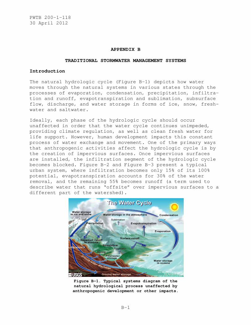
The natural hydrologic cycle (Figure B-1) depicts how water moves through the natural systems in various states through the processes of evaporation, condensation, precipitation, infiltra-tion and runoff, evapotranspiration and sublimation, subsurface flow, discharge, and water storage in forms of ice, snow, fresh-water and saltwater.
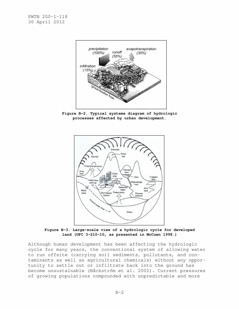
Ideally, each phase of the hydrologic cycle should occur unaffected in order that the water cycle continues unimpeded, providing climate regulation, as well as clean fresh water for life support. However, human development impacts this constant process of water exchange and movement. One of the primary ways that anthropogenic activities affect the hydrologic cycle is by the creation of impervious surfaces. Once impervious surfaces are installed, the infiltration segment of the hydrologic cycle becomes blocked. Figure B-2 and Figure B-3 present a typical urban system, where infiltration becomes only 15% of its 100% potential, evapotranspiration accounts for 30% of the water removal, and the remaining 55% becomes runoff (a term used to describe water that runs “offsite” over impervious surfaces to a different part of the watershed).
Figure B-1. Typical systems diagram of the natural hydrological process unaffected by anthropogenic development or other impacts.
PWTB 200-1-118 30 April 2012
B-2
Figure B-2. Typical systems diagram of hydrologic
processes affected by urban development.
Figure B-3. Large-scale view of a hydrologic cycle for developed
land (UFC 3-210-10, as presented in McCuen 1998.)
Although human development has been affecting the hydrologic cycle for many years, the conventional system of allowing water to run offsite (carrying soil sediments, pollutants, and con-taminants as well as agricultural chemicals) without any oppor-tunity to settle out or infiltrate back into the ground has become unsustainable (Båckström et al. 2002). Current pressures of growing populations compounded with unpredictable and more

PWTB 200-1-118 30 April 2012
B-3
intense precipitation from climate change events is impacting both people’s quality of life and their livelihoods. On Army installations, these pressures come from slightly different sources, but the outcomes are very similar. The "Grow the Army” initiative as well as the 2005 Base Realignment and Closure process is affecting population location and densities on mili-tary installations. These impacts are anticipated to affect all systems of military installations, and historic districts are no exception. Power provision, water supply, and stormwater manage-ment are three main at-risk systems on DoD and federal property; this publication will focus on implementing sustainable storm-water management systems in historic districts.
Stormwater management within historic districts has been done in a conventional manner, and implementing new and different (i.e., sustainable) stormwater management technologies within the ex-isting system is challenging. There is usually lack of precedent of any type of GI technologies installed on or around historic properties. Without this precedent, proposed modifications gen-erally result in a negative evaluation, on the basis that the added ‘new’ technology will have an adverse effect on the his-toric quality of the property.
Development of Traditional Stormwater Management Systems
Stormwater management is not a modern term. The central concept arises from the basic need to deal with the water entering a specified area of land, whether by precipitation or on-site flow. From past to contemporary human settlements around the world, fresh water has been necessary for sustaining human life. As civilizations developed around agricultural systems, water was needed for irrigation. As human settlements became less ephemeral and developed into permanent and built “urban” sys-tems, water necessarily became more than an amenity. Not only did fresh water need to be brought onsite for the previously mentioned purposes, but excess water became a “nuisance.” The more permanent, built structures and paved environments that people created as civilizations developed resulted in more im-pervious ground surface. During precipitation and heavier storm events, wet seasons and snow/ice melt, water was not able to infiltrate into the ground as it had in the previous natural condition. Not only would flooding occur, but human and animal waste would be washed into the flowing water during certain events and be redistributed around the human environments, which in turn created unsanitary conditions, disease, and human mor-tality.

PWTB 200-1-118 30 April 2012
B-4
Motivated by the prospect of healthier living conditions (including but not limited to availability of fresh water for consumption and irrigation, healthy living environments and stormwater controls), water management was developed. Freshwater springs were found, and water was piped via innovative systems into town centers and out to agricultural fields. Both above-ground and underground systems were created to capture and con-vey stormwater and other excess water offsite. The offsite con-veyance of excess water took advantage of the natural hydrologic system, providing delivery to a major moving body of water near-by. In this way, excess water and wastes were easily conveyed out of sight, out of mind, while flooding was controlled and/or prevented. Many components of early stormwater management sys-tems were paved in order to maintain more of a permanent or long-term solution to stormwater management; however, natural systems and infiltration opportunities were used as well, if only because less materials and labor effort were needed. If these ancient systems were copied and installed within today’s urban environments, with minimal exception, they would be con-sidered GI technologies, and would contribute to the sustaina-bility of the built environment and stormwater management plan. Appendix E contains further information on GI, and Appendix I provides historic (and contemporary) examples of GI.
Earlier stormwater management systems provide the core of many older US urban stormwater systems and are called “combined sewer and stormwater systems.” These combined systems carry both sew-age (human and industrial waste water) as well as stormwater away from the city center, generally depositing them downstream into a nearby river or stream. This system was developed in order to avoid having water waste running in open ditches and gutters within urban centers, and at its inception seemed to work well. However, this system was shown to be a sub-optimum solution, as serious issues arose. Many of the larger urban areas within the United States have had to overcome these out-dated combined sewer systems, re-engineering certain elements of their sewage systems to accommodate local environmental condi-tions and known problems.
Conventional Stormwater Management Case Study – Chicago, IL
The history behind water and stormwater management by the City of Chicago provides a relevant case study of stormwater system development.
The largest city in Illinois, Chicago is located at the conflu-ence of the Chicago River and Lake Michigan. The first non-

PWTB 200-1-118 30 April 2012
B-5
indigenous settler, Jean Baptiste Point du Sable, permanently settled in the area in the 1780s. In 1795, an area that is now part of Chicago was obtained for use as a military post by the United States through the Treaty of Greenville. Then, the Treaty of Chicago in 1833 turned the rest of Chicago’s land over to the United States, and the city was founded on August 12, 1833.
Chicago’s strategic location gave the city the advantage of a huge reservoir of drinking water (Lake Michigan) literally right beside the city, with shipping and transportation opportunities for commerce, trade, and travel along the Chicago River. Due to its location and the growth of Chicago, the Chicago River also served as the default output destination for the drains that served the city’s conventional combined stormwater, sewage, and wastewater system.
This combined system probably solved Chicago’s pollution prob-lems at first, while the city was relatively small. However, by 1885, a rainstorm caused so much sewage-contaminated river water to enter Lake Michigan that the city’s drinking water became contaminated. The subsequent outbreak of cholera and typhoid killed more than 90,000 people, compelling the city to find a way to prevent polluted water from entering the lake.
In 1889, the Metropolitan Sanitary District of Greater Chicago was created to tackle the problem of keeping the city’s drinking water safe while maintaining the facility to dispose of the city’s wastewater. Their efforts culminated in construction of the Chicago Sanitary and Ship Canal. This canal connected to the Chicago River, and reversed the flow so that, instead of flowing into Lake Michigan, the water flowed down and connected with the Des Plaines River (a tributary of the Mississippi River). A locks system was installed so that the river and canal eleva-tions could be controlled, while preventing Lake Michigan from draining out through the newly constructed canal. While this engineering feat prevented the lake from becoming polluted, the levels of pollution in the Chicago River were not reduced. A concurrent problem was that sewer overflows were still an issue; even 1/3 inch of precipitation caused sewer system overloads and combined sewer overflows (CSOs) would enter the river. Thus, the Chicago River remained polluted, and the canal/river/locks sys-tem was not enough to prevent pollutant-filled backflows from reaching Lake Michigan during heavy storms.
These problems remained until 1972, when the Metropolitan Water Reclamation District of Chicago (formerly the Metropolitan Sani-tary District of Greater Chicago) initiated the Tunnel and Res-

PWTB 200-1-118 30 April 2012
B-6
ervoir Program (TARP). This program consisted of building large-scale, multi-purpose subsurface tunnels and surface reservoirs that captured, conveyed, and stored combined sewage during storms. This system was used to store the excess polluted water during and after storm events, until it could be treated by existing treatment plants. TARP was successful upon its comple-tion; a key indicator was the rise in the number of fish species able to survive in the Chicago River system. In 1974 (before TARP was finished), the river held 10 fish species and by the year 2000, there were 63. This increase did not occur all at once, since additional TARP segments came online throughout the subsequent years. Also during this time period, supplemental aeration of the waterways was performed, and other treatment plant performance improvements were made. The engineered TARP facilities are still used by the City of Chicago today; however, with increased development and urban growth, the quality of Chicago’s surface waters still needs to be improved.
Current approaches being implemented in Chicago are comprehen-sive and focused on implementing and promoting demonstration projects that promote and utilize stormwater Best Management Practices (BMPs) at the source level. This, in turn, is designed to reduce stormwater runoff and improve the quality of water that is input into the city’s combined sewage system. These BMPs involve Low Impact Development (LID) practices and technologies, as discussed in Appendix I of this publication.
The City of Chicago’s conventional, combined sewer system has utilized traditional stormwater management principles. These principles, as discussed earlier, are intended to convey the excess water from a storm event away from the centers of human activity, without comprehensive regard to consequences from pollution or sewer backflow effects. While this method generally decreases the risk of onsite flooding, it does not directly address water quality issues, nor does it yield significant sustainable environmental benefits.
An alternate type of system (the separated stormwater and sewage system) was phased in during the expansion of American suburbia after World War II (WWII). In these systems, sewage was routed to water treatment plants, and stormwater was directed to out-falls in local streams and rivers. This practice solved the pollution problems and backflow issues present in combined sewer systems; however, issues with erosion and sediment control in stormwater persisted. Generally, separate sewage and stormwater systems have not been retrofitted within large cities due to the

PWTB 200-1-118 30 April 2012
B-7
tightly built urban fabric and difficulty of reworking the sub-surface channeling system.
Stormwater Management Goals, Objectives, and General Technologies
The following text explores the general function and configura-tion of conventional stormwater management systems. The planning and design process, considerations, and tools used when planning systems specifically for stormwater will also be explained. Keep in mind, however, that this will be a generalized summary and explanation of components and process; actually planning a stormwater management system requires complex calculations and professional engineering assistance.
A typical, conventional stormwater management system focuses on moving stormwater to the periphery of inhabited areas. The main objectives typically fulfilled for a municipality by implement-ing a stormwater management system are listed below (Debo and Reese 1995).
• protect life and health • minimize property losses • enhance floodplain use • ensure a functional drainage system • protect and enhance the environment • encourage aesthetics • guide development • support provision of a safe municipal water supply
The planning process to create stormwater management systems should be on a large scale, either site-wide or master-plan level, so that the system will have enough capacity to transport and store excess flows. This determination generally involves outlining watershed areas, based on topography and natural hydrologic processes. The large-scale accounting of natural systems within built areas requires calculating the volumes and rates of overland flow and relating them to land cover types.
Water is channeled from impervious surface areas into storm systems through swales, catch basins, area drains, trench drains, or drain inlets. Water is then routed through large subsurface pipes or open canals or channels. Along this sequence, temporary storage may be used to slow the outflow of stormwater and to provide a capacity buffer for larger scale precipitation events. Devices used for these purposes would

PWTB 200-1-118 30 April 2012
B-8
include cisterns, retention and detention ponds, and flood basins as well as environmentally friendly devices such as bioretention ponds or bioswales to allow subsurface water infiltration. In channeled areas, weirs, check dams, and drop structures are used to control flowing water energy, velocity, and erosive potential, and sediment ponds and settling basins are used to remove suspended sediments that cause siltation. In this way, water is channeled and directed away from built urban areas, with temporary storage as needed to maintain drain function, prevent interim flooding, and avoid potential negative impacts of excess water in the built environment.
Design Process
To successfully plan a stormwater management system, a large-scale assessment must be done to ensure that any ensuing design will be efficient in providing adequate drainage and catchment volume for both small and large precipitation events, while also adhering to safety and aesthetic standards.
The first step in planning a large-scale conventional urban stormwater management system requires data collection to gain knowledge properties and measurements.
• size and character of catchment area • soil classification and hydraulic properties, groundcover,
land use • average precipitation and losses • runoff as a percentage of average rainfall • peak flow or peak discharge
An inventory of watershed features should also be documented so that the planned system may be more compatible with the environ-mental context. Data on watersheds, existing hydrologic data and drainage system maps, water quality data, and land use data must all be included in a preliminary desktop survey.
Once a desktop survey has been done and data collected, estab-lishment of design frequency and risk (of flooding) for the urban area is advised so that the risks and uncertainties in-volved can be matched to the type of design involved in the stormwater management system. This risk-based analysis will allow consideration of flood events relative to periodic storm cycles. When weather patterns are considered in the long-term, storms define a peak storm magnitude that can be expected to occur about every 5 or 10 years. (This pattern also can be thought of as a relative probability: a 5-year storm magnitude

PWTB 200-1-118 30 April 2012
B-9
has a 20% probability that it could be equaled or exceeded in any single year.) For the longer term, a 50-year storm defines a peak storm that occurs roughly every 50 years, and a 100-year storm defines the storm event that occurs once every 100 years.
Risk-based design is becoming more common, since it allows engi-neers to anticipate realistic conditions and design around reli-ability estimates rather than for specific storm events, which, considering climate change, are likely to change in the near future. Instead of designing for a particular storm and flood magnitude, an engineer with the right type of high-quality data to inform the risk analysis will be able to estimate performance characteristics of stormwater management systems and components, with the ability to predict that a levee will be able to contain a 100-year flood with 95% reliability and a 500-year flood with 50% reliability (Debo and Reese 2003).
Designing for risk involves establishing a design storm frequen-cy so that drainage facilities can accommodate specified amounts of discharge within a given return period. The designer must be knowledgeable about the different capabilities of the drainage facilities to be utilized. For example, major urban conveyance systems are often designed for 100-year floods; however, the range of design frequencies is generally between 25-year to 100-year storm events. Smaller conveyance systems are generally designed for 5-year to 10-year storm events. Storm drains are designed to accommodate a 10-year flood; however, design fre-quency ranges from 5-year to 25-year storms (Debo and Reese 2003).
A final review of design frequency for the entire stormwater management system should be undertaken to ensure that unexpected flood hazards are not present. Again, with climate change alter-ing the frequency and intensities of storm events, these risk-based analyses should prove more essential to watershed manage-ment in the coming years.
With knowledge of the design frequency and risk that the storm-water system should adhere to, the design phase of the storm-water management system can begin. The design phase is where hydrologic analyses are done in order to define the drainage basin, channel and conveyance system characteristics, floodplain characteristics, and meteorological characteristics (Debo and Reese 2003).
From these analyses, various methods may be used (these should be chosen according to local environmental conditions relative

PWTB 200-1-118 30 April 2012
B-10
to local circumstances) to calculate the system design. An iter-ation of the steps within this design process is outlined below (adapted from Debo and Reese 2003). 1. Determine requirements (peak flow, hydrograph, etc.) and accu-
racy, and select a design procedure. 2. Collect necessary data. 3. Identify design storm criteria and develop the design storm or
rainfall. 4. Compute time of concentration or other lag times required. 5. Determine rainfall excess if appropriate to the methodology. 6. Compute peak rate of runoff or flood hydrograph. 7. Perform detention storage or channel routing, if appropriate. 8. Estimate or test sensitivity to engineering judgments and data
error ranges. Adjust approach as appropriate. 9. Document all estimates and calculations in detail.
Cost-Benefit or Return on Investment
The cost-benefits of the proposed stormwater system must also be considered, to ensure that the project may be constructed with available finances. Costs to install such comprehensive systems are substantial, but an advance analysis can be made to estimate the return on investment (ROI) once the system is in place. Generally, in urban areas, the long-term benefit of having a functioning system in place exceeds the high short-term cost of initial install. The following is a list of the costs to be considered (Debo and Reese 2003).
• Capital costs, including cost of planning, design, construc-tion, land or easements, surveys, and other startup elements.
• Operating costs, including labor and expenses, replacement and repairs, maintenance costs.
• Risks, including costs for damages and restoration if storm-water protection was not provided.
With any conventional stormwater management system, certain pitfalls exist that can reduce its effectiveness. These major pitfalls relate to the management of the design and implementa-tion of the system, as well as post-installation system manage-ment and care. Debo and Reese (2003) identify these pitfalls, given below.
Long-term Issues
• Long-term goals or policies are not well identified; thus enforcement of management standards are lacking.
PWTB 200-1-118 30 April 2012
B-11
• Systems are not equipped to deal with changing future conditions; systems are not coordinated to integrate with other planning functions.
• Stormwater management plans are not always accessible enough to be compatible with on-the-ground user groups. Plans may be too advanced and complicated, do not func-tion as “tools,” require complex computer analysis, or may be written for an expert audience (general user audi-ences may not be expert).
Legal, Financial, Organizational, and Technical Issues
• Stormwater often managed as “piecemeal” technology inputs as opposed to system-management solution.
• Little knowledge of current state-of-repair of the cur-rent system, as well as maintenance requirements, pre-vents adequate budgeting for maintenance activities.
• Local infrastructure is in disrepair and remains beyond the financial or technical ability of homeowners or mu-nicipality.
• Planning and design policies either do not exist within municipalities or are not well enforced.
• Run-on from offsite was unanticipated and caused problems because of no interjurisdictional cooperation.
• Funding was inadequate and/or poorly targeted to meet ac-tual needs.
• Engineering methods are not uniform.
• Often incomplete data exist, making engineers use inferi-or information for systems designs that are then inade-quately and sometimes incorrectly implemented.
• There is little knowledge or concern for environmental aspects of urban runoff.
Day-to-Day Issues
• Planners are unable to predict downstream and systemic impacts from potential developments and stormwater con-trols.

PWTB 200-1-118 30 April 2012
B-12
• Regular preventive maintenance was not done; rather, maintenance was prioritized by public comment or politi-cal pressure.
• Erosion control measures were either not deemed necessary or prematurely dismissed as not possible.
• Overall design assessment was not done as a dispropor-tionate amount of time was spent on detailed drainage calculations rather than design capability and optimiza-tion.
• Development process was not mature enough to ensure com-pliance.
• Many development control policies are understood by local engineers but not documented. Without documentation, de-tails, coordination, and design development, opportuni-ties are missed.
It should also be noted that public education and involvement often is not emphasized or is lacking.
Regarding the cost of stormwater systems, the question generally becomes one of why a stormwater management system would not be considered, since the cost-benefits are large. The benefits are seen by comparing potential cost of a stormwater system to po-tential financial damages and losses if such a system were not in place. (Ideally, the planned stormwater system will be an efficient system without excess cost but able to manage the largest and most intense events with relative ease.) Debo and Reese (2003) present a useful graphic (Figure B-4) that shows the relationships between monetary loss (damage = “how expen-sive”), storm intensity (stage = “how high”), and storm frequen-cy (frequency = “how often”).

PWTB 200-1-118 30 April 2012
B-13
Figure B-4. Relationships between monetary loss, storm intensity,
and storm frequency (Debo and Reese 2003).
Chart A and Chart B in Figure B-4 show individual assessments, while Chart C shows a synthesized assessment. The synthesized Chart C shows the magnitude of monetary loss relative to storm frequency, assuming that the storm intensity element is the common denominator. These relationships show that thresholds must be established by the municipality or governing entity that manages the risks associated with stormwater damage. Once the risks (e.g., impacts on human health and loss of life, impacts to residential and nonresidential structures, utility damage) are assessed and thresholds established, the stormwater management system can be adjusted to ensure that urban infrastructure is protected, the stormwater management system is cost-efficient, and a final financial cost-benefit analysis can be performed.
Debo and Reese (2003) also present a step-wise “Typical Benefit-Cost Analysis” that shows the type of considerations that should be taken (Table B-1).
B
C
A

PWTB 200-1-118 30 April 2012
B-14
Table B-1. Typical benefit-cost analysis (Debo and Reese 2003).
Sustainability as an Issue in Stormwater Management
With current-day regulatory and environmental pressures as well as sustainability concerns coming from the general population, conventional stormwater management systems need to be re-evaluated (Water Environmental Research Foundation [WERF] 2009). Regulatory concerns are focused on reducing nonpoint source pollution, as well as finding ways to deal with current aging and out-of-date stormwater systems in many urban areas that have become too expensive to repair. Environmental concerns stem from general environmental degradation and the disruption of natural processes all compounded by the changing climate and environmen-tal consequences. Sustainability concerns come from communities’ general dissatisfaction with the current situation as people become more aware of environmental issues while expecting higher quality green space and aesthetic amenities.
If nothing is changed, the flood protection stormwater manage-ment systems provide will become obsolete and damage costs will rise. The future viability of stormwater management relies on integrating natural water systems with new, flexible designs

PWTB 200-1-118 30 April 2012
B-15
that respond to changing climate variables. BMPs and green in-frastructural systems are tools stormwater managers can use to more effectively manage stormwater.

PWTB 200-1-118 30 April 2012
C-1
APPENDIX C
CURRENT REGULATIONS AND LEGISLATION
Preservation of Historic Properties
The NHPA requires federal agencies to consider the historic importance of properties under their administration. Preserving historic properties conveys the nation’s heritage through in-creasing the knowledge of historic resources. This includes establishing better means of identifying and administering fed-eral properties to maintain their cultural, educational, aes-thetic, and economic benefits. The NHPA establishes the NRHP and NHL on which qualifying properties can be listed. SHPOs and federal agencies are to work together identifying, nominating, and maintaining the historic characteristics of eligible proper-ties (NHPA 2006).
Significant in NHPA are the actions outlined in Sections 106 and 110. Section 106 requires federal agencies to consider the ef-fects of undertakings on historic properties while also giving the Advisory Council on Historic Preservation (ACHP) an oppor-tunity to comment on proposed actions. This review process in-cludes all stakeholders to determine if actions could poten-tially affect historic properties. The process includes identi-fying historic properties, assessing potentially adverse effects, resolving adverse effects, and implementing the terms of the agreement (ACHP 2002). Section 110 expands and makes explicit a federal agency’s responsibility for identifying and protecting historic properties by establishing a preservation program to identify, evaluate, nominate, and protect historic properties under their administration. Agency planning is re-quired to consider the historic, archaeological, architectural, and cultural values conveyed by historic properties. If an agen-cy has a historic property, effort must be made to adaptively reuse the property before new construction is considered. Sec-tion 110 also establishes the criteria for integrating preserva-tion planning into all federal agency programs (National Park Service 1998).
EO 11593 directs federal agencies to provide leadership in pre-serving the historic and cultural environment of the United States. Leadership includes proper administration, management, and programming of culturally significant historical, architec-tural, or archaeological sites. In turn, federal programs should contribute to the preservation of nonfederally owned sites and
PWTB 200-1-118 30 April 2012
C-2
objects of cultural significance. With this EO, federally owned properties of historical significance should be inventoried, surveyed, and cataloged. If a property must be demolished, meas-ured drawings, photographs, and maps should be created and de-posited in the Library of Congress as part of the Historic American Building Survey. The guidance in this EO supplements the National Environmental Policy Act of 1969, the National Historic Preservation Act of 1966, the Historic Sites Act of 1935, and the Antiquities Act of 1906.
The Public Buildings Cooperative Use Act of 1976 amends the Public Buildings Act of 1959 to preserve buildings of historical or architectural significance when economically feasible through their reuse as federal public buildings. Public buildings may accommodate commercial, cultural, educational, and recreational activities and should be adapted so that the accessibility of the building must meet the needs of the physically handicapped. When the federal government decides to locate in a geographical area a survey of historically, architecturally, and culturally significant buildings must be conducted determining the area’s suitability for the needs of the federal government.
Environmental Legislation Relating to Stormwater Management
NEPA unifies environmental decision-making processes across federal agencies. It requires federal agencies to consider envi-ronmental consequences related to land use, air and water quali-ty, wildlife and habitat, socioeconomic factors, human health and safety, as well as natural and historical resources. The policy contains an “action-forcing” provision that compels agen-cies to document their efforts to comply with the policy set forth in the law (Smythe 1997: 12). Agencies are directed to use a “systematic, interdisciplinary approach” ensuring the integra-tion of natural and social sciences and environmental design arts into planning and decision making (Clark 1997: 17). As a result, federal agencies are required to conduct EAs and EISs to make informed environmental decisions when considering and plan-ning new projects including retrofitting existing facilities (NEPA 2006). Agencies are also required to seek advice, partici-pation, and comments from appropriate governmental agencies and stakeholders, and inform interested public and private organiza-tions of their activities (UFC 3-210-10, 2004).
Clean Water Act
The CWA, as amended by the Federal Water Pollution Control Amendments of 1972, with the amendments of the CWA of 1977 and

PWTB 200-1-118 30 April 2012
C-3
the Water Quality Act of 1987, governs the protection of the quality of the Waters of the United States. It is the principal federal statute protecting navigable waters and adjoining shore-lines from pollution. Specific sections that pertain to storm-water management are:
Section 303: Total Maximum Daily Loads (TMDLs)
This section states that every US State and Territory is required to generate and submit to the Environmental Pro-tection Agency (EPA) a list of impaired waters, ranked by their assigned TMDL. This enables the EPA to track pollu-tion loadings among water sources; it also provides the baseline data for control of point and nonpoint source pol-lution. States are then required to develop mitigation plans to confront and solve the apparent pollution issues.
Section 311: Oil and Hazardous Substances Liability
Section 311 establishes federal requirements pertaining to oil and hazardous substances, establishing a program for “preventing, preparing for, and responding to oil spills that occur in navigable waters of the United States.” The EPA thus requires certain facilities to maintain an oil spill prevention, control, and countermeasures plan, which guards against oil spills reaching navigable waters. EPA implements these provisions of the CWA through a variety of regulations, including the National Contingency Plan and the Oil Pollution Prevention regulations.
Section 319: Nonpoint Source Management Program
The Nonpoint Source Management Program provides greater federal leadership to help focus nonpoint efforts at state and local levels. Grants awarded by the EPA to provide funding for this program support a wide variety of activi-ties including technical assistance, financial assistance, education, training, technology transfer, demonstration projects and monitoring to assess the success of specific nonpoint source implementation projects. Although Section 319 does contain enforcement measures, Section 303 require-ments provide this by necessitating control, mitigation, and prevention plans for impaired waters.
Section 401: Certification and Wetlands
Section 401 grants states and tribes the authority to re-view and approve, condition, or deny all federal permits or licenses that might result in a discharge to state or trib-

PWTB 200-1-118 30 April 2012
C-4
al waters, including wetlands. This provides a unified ap-proach to ensure that all activities comply with state wa-ter quality standards. The major federal licenses and permits subject to Section 401 are Section 402 and 404 per-mits (in nondelegated states), Federal Energy Regulatory Commission hydropower licenses, and Rivers and Harbors Act Section 9 and 10 permits. In addition, states and tribes look at whether the activity will violate effluent limita-tions, new source performance standards, toxic pollutants, and other water resource requirements of state/tribal law or regulation.
Section 402: National Pollutant Discharge Elimination Sys-tem (NPDES) Program
The CWA prohibits the discharge of point source pollution into US waters unless they are authorized by NPDES permit. The NPDES controls direct (point source) discharges and contains limits establishing pollutant monitoring and re-porting requirements. Some facilities such as industrial and construction facilities need an NPDES permit to allow them to discharge stormwater from the site. The EPA has au-thorized 40 states to administer the NPDES program, and many states follow EPA guidelines for proposed aquatic life and human health criteria relative to 126 priority pollu-tants (EPA 2011a).
Section 404: Regulation of Dredge or Fill Material
Section 404 regulates the discharge of dredged or fill ma-terial into Waters of the United States (including wet-lands). No discharge of dredged or fill material may be permitted if: “(1) a practicable alternative exists that is less damaging to the aquatic environment or (2) the na-tion’s waters would be significantly degraded” (EPA 2004). Although certain farming and forestry activities may be ex-empt, all the activities regulated under this program in-clude fill for development, water resource projects (such as dams and levees), infrastructure development (such as highways and airports), and mining projects (EPA 2011b).
Coastal Zone Management Act of 1972
DoD facilities located in coastal states where Coastal Zone Management Programs have been developed must ensure that nonpoint source pollution control programs are in place to protect the coastal zone and associated Waters of the Unit-ed States.

PWTB 200-1-118 30 April 2012
C-5
Safe Drinking Water Act of 1974 with the 1986 Wellhead Protection Program Amendment
The Wellhead Protection Program protects groundwater recharge pathways around public water system wells. Any pollutants contained in runoff that could potentially infiltrate into the groundwater must be appropriately dealt with before affecting the subsurface aquifer.
Energy Policy Act of 1992
The Energy Policy Act created conservation and energy-efficiency requirements for federal government as well as consumers. This policy requires federal agencies to install energy and water conservation measures with expected ROI figures. This policy is applicable to site water management since stormwater storage in rain barrels and cisterns can be used to subsidize a facility’s water requirements, contributing to energy and water conservation expectations.
Department of the Navy “LID Policy,” 16 November 2007
This Navy policy has set a goal within the Navy of a “no net increase” in the amount of stormwater that escapes into the ecosystems surrounding Navy and Marine Corps facilities and installations nationwide (DON 2007). The Navy has rec-ommended that LID technologies be used in order to help meet this goal as opposed to conventional stormwater man-agement systems. If a site is deemed inappropriate for the implementation of LID, it must go through a waiver process where the site would be reviewed and approved by a regional engineer (DON 2007).
Energy Independence and Security Act of 2007
EISA 2007, Section 438 contains policy establishing a set of requirements for stormwater runoff for federal develop-ments and redevelopments, with the main goal of preserving stormwater flow and infiltration in its original pre-development condition. The Act states:
The sponsor of any development or redevelopment pro-ject involving a federal facility with a footprint that exceeds 5,000 square feet shall use site plan-ning, design, construction, and maintenance strategies for the property to maintain or restore, to the maxi-mum extent technically feasible, the predevelopment hydrology of the property with regard to the tempera-ture, rate, volume, and duration of flow.

PWTB 200-1-118 30 April 2012
C-6
Federal agencies can comply using a variety of stormwater management practices often referred to as “green infra-structure” or LID practices, including for example, reduc-ing impervious surfaces and using vegetative practices, porous pavements, cisterns, and green roofs (EPA 2010c).
Maintenance of stormwater is to be done to the maximum ex-tent technically feasible. Before this Act, the Army’s stormwater regulations mainly consisted of pollutant remov-al. Increases in runoff and peak discharge were regulated by state and local flood control programs. Because of knowledge collected over 20 years, the Army recognizes that conventional approaches to stormwater runoff have not done an adequate job in protecting our nation’s waters.
Army Regulation 200-1
AR 200-1 outlines environmental policies and designates program requirements in order to comply with federal poli-cies. Chapter Four, Section 2 outlines the policy for water resource management, specifically Section E entitled “Stormwater Management.” This section pertains to policy controlling or eliminating sources of pollution so as to not contaminate water bodies or ground water. A second pol-icy uses abatement measures for nonpoint source runoff from facilities, construction, and land management activities. Program requirements include obtaining specified permits, providing stormwater management plans, and stormwater pol-lution prevention plans (Department of the Army [DA] 2007).
Executive Order 13148, Greening the Government through Leader-ship in Environmental Management, 2000
The aim of Section 204 of EO 13148 is to lessen the amount of pollutant released from various Army agencies. The goal of EO 13148 is for agencies to reduce their Toxic Release Inventory to 10% annually or 40% overall. Section 304 man-dates that each agency must develop a Pollution Prevention Program that compares life-cycle costs of traditional waste removal to an alternative option’s life-cycle cost, in which the reduction of chemicals and pollutants happens at the source. To execute these goals, each agency is required to write an Environmental Management Strategy showing that the requirements of this order are incorporated into their environmental directives, policies, and documents (EO 13148). This EO has since been rescinded by EO 13423; how-ever, it is important to understand its prior requirements.

PWTB 200-1-118 30 April 2012
C-7
Executive Order 13423, Strengthening Federal Environmental, Energy, and Transportation Management, 2007
Section 2 of EO 13423 sets federal agency goals to reduce water consumption by 2008 to the baseline of water consump-tion in 2007, after which an annual 2% reduction will occur so that by the year 2015 an overall 16% reduction in water consumption is achieved. This EO also contains policy spec-ifying that federal agencies must reduce toxic and hazard-ous chemical use and disposal. EO 13423 rescinds EO 13148; however, it is important to understand the previous EO’s requirements.
Executive Order 13514, Federal Leadership in Environmental, Energy, and Economic Performance, 2009
EO 13514 expands on the energy reduction and environmental performance requirements set forth in EO 13423, in that it sets certain environmental targets for federal agencies. Targets that pertain to water and stormwater management are as follows: Reduce by 2% annually both potable water inten-sity (baseline 2007, 26% total reduction by 2020), as well as industrial, landscaping, and agricultural water intensi-ty (baseline 2010, 20% total reduction by 2020); ensure 95% of all new contracts require sustainable products and ser-vices; implement water management strategies, including wa-ter efficient and low-flow fixtures; manage existing buildings to reduce energy, water, and materials consump-tion; implement and achieve objectives in the EPA’s Storm-water Management Guidance.
Memorandum for Sustainable Design and Development Policy Update (Environmental and Energy Performance, Revision, 2010)
This memorandum was issued 27 October 2010 by the Assistant Secretary of the Army for Installations, Energy, and Environment. This policy memorandum aims to improve high-performance green buildings standards for the Army. The memorandum stated that:
“Energy security, sustainability and efficiency are a national security imperative. This policy supports the Army’s global missions in a cost-effective, safe, and sustainable manner that will benefit Army Soldiers, Families, and the entire Nation.”

PWTB 200-1-118 30 April 2012
C-8
Army Net Zero Initiative
This Army-wide initiative is a holistic approach comprised of five steps that will enable sustainable resource manage-ment for energy, water, and waste with the end goal of cre-ating a “net zero” Army. The five, interrelated steps are: reduction, repurposing, recycling and composting, energy recovery, and disposal. This initiative is seen as a “force-multiplier” and “stabilizing factor” that will ena-ble the Army to steward available resources, manage costs, and provide for a sustainable future for soldiers, families and civilians. The Net Zero Water element of the initiative focuses on efficient management for potable water, aquifer management, rainwater harvesting, water recycling, sewage management, stormwater management, and desalinization (DA 2011; OASA[IE&E] 2010).
Leadership in Energy and Environmental Design Green Building Rating System
The LEED System, developed by the US Green Building Coun-cil, is an internationally recognized green building certi-fication system to provide third-party verification that any building, development, or community was designed and built utilizing sustainable practices. The system is points-based, with points awarded relative to the sustaina-bility of the building practice used within the project. Projects may earn a LEED certification of “Certified,” “Silver,” “Gold,” or “Platinum” relative to the number of green technologies and practices that qualify under the certification system. The DoD encourages agencies to use the LEED checklist and apply for certification. Within the Army, the Sustainable Project Rating Tool was previously used; however, it has been replaced with the LEED system as a guiding principle for development [OASA(I&E) 2006].
The LEED system awards points to projects where disruption of natural water flows are reduced by minimizing stormwater runoff, increasing onsite infiltration, and reducing con-taminants.
Unified Facilities Criteria
The UFC system “is prescribed by MIL-STD 3007 and provides planning, design, construction, sustainment, restoration, and modernization criteria, and applies to the Military De-partments, the Defense Agencies, and the DoD Field Activi-ties in accordance with USD(AT&L) Memorandum dated 29 May

PWTB 200-1-118 30 April 2012
C-9
2002. UFC will be used for all DoD projects and work for other customers where appropriate” (UFC 3-210-10, 2010).
Other Voluntary Programs and Agreements
A variety of more locally based or state-run programs exist in which federal agencies may participate that are aimed at preserving and restoring water quality, including storm-water management. Participation in such programs is encour-aged within the DoD to promote voluntary compliance, education, and personnel training.
DoD Retrofit Policy
The general policy regarding retrofitting buildings within the DoD was outlined in the 2004 release of UFC 3-210-10 (now super-seded by the 2010 version), which notes that:
“…old DoD facilities were developed either with tradi-tional approaches or with no stormwater management at all. Eventually, stormwater management components will have to be installed replaced or retrofitted – a costly task. DoD will inevitably need to replace pipes and dredge stormwater ponds.”
This guidance directly pertains to this PWTB, as it bridges a gap between older facilities that were not built to modern standards but are up for retrofitting, thus necessitating the integration of historic properties with newer stormwater manage-ment plans and technologies that adhere to current regulation and policy. It should be noted that the 2010 version does not contain this exact text. This can be attributed to the develop-ment of policy and continued implementation of sustainability actions within the DoD that has raised awareness of stormwater management and building retrofitting issues, likely rendering the statement unnecessary within the 2010 version.
PWTB 200-1-118 30 April 2012
D-1
APPENDIX D
UNDERSTANDING THE HISTORIC DISTRICT
This document focuses on implementing sustainable stormwater management systems in historic districts that have been invento-ried, evaluated, and are either eligible for or listed on the NRHP. Preservation planning and management varies between in-stallations; this PWTB establishes general guidelines to aid cultural resource managers, natural resource managers, and pub-lic works personnel in determining appropriate stormwater tech-nologies suitable for historic districts. These guidelines will help managers at each installation determine the unique charac-teristics of their location to ultimately evaluate acceptable and unacceptable actions. Through communication and cooperation with management personnel, state preservation offices, and fed-eral agencies, Army installations can meet both preservation and natural resource legislative requirements while incorporating historically compatible sustainable stormwater systems into districts.
Historic districts are areas in a cantonment conveying the his-tory of the installation. Cultural resource legislation requires federal agencies to protect their historic resources and, as a consequence, military historic districts are evaluated as eligi-ble or listed on the NRHP. Historic districts must be preserved in a manner that conveys their historic significance; new under-takings in the district must be carefully evaluated for poten-tially adverse effects. While preservation legislation allows for adaptively reusing buildings, retrofitting landscapes with sustainable technologies presents many challenges and has not been addressed through policy or regulation. In general, histor-ic landscapes have some flexibility for modification; however, care must be taken in choosing historically appropriate designs and materials for any new project (Advisory Council on Historic Preservation, 2002).
Establishing Historic Context
The Secretary of the Interior’s Standards and Guidelines for Archaeology and Historic Preservation outlines standards to be followed for preservation planning. Standard I of these Guide-lines recommends establishing the historic context of an area. Historic contexts organize the relationships that influenced development of the built environment and convey historical sig-nificance. Historic districts have several scales of context
PWTB 200-1-118 30 April 2012
D-2
from small architectural detailing to large, district-wide pat-terns. With the goal of incorporating new technology into a designated historic district, the historic context provides a basis for decision making (National Park Service 2001). Historic contexts are encompassing and should include a period of signif-icance for the constructed as well as natural environments. The period of significance is the time period that preservation efforts aim to enhance. The period of significance provides a point of reference to which any additions to or subtractions from a historic district are evaluated (Advisory Council on Historic Preservation, 2002).
Historic landscape reports are important documents that outline periods of significance and character-defining features, and give guidance on maintaining the historic qualities of a dis-trict. Knowing the history of a historic district’s development is critical in understanding how to adapt existing infrastruc-ture to meet new sustainability guidelines while also complying with NHPA requirements. The history of a district establishes a period of significance, relating the physicality of the canton-ment to the cultural influences that shaped it. This baseline is used when consulting on proposed changes in a historic district.
This information determines whether or not the implementation of certain technologies, materials, and locations are in keeping with the established historic character. In accordance with the NHPA, any undertaking can carry with it an adverse effect; a proposed intervention could be incompatible and distract from the historic feeling of an area. The complexity of historic military landscapes is illustrated as:
“…landscapes that are uniquely shaped in support of a particular military mission and are associated with historically important persons or events, or is an important indicator of the broad patterns of history.
Landscape characteristics are the tangible evidence of the activities and habits of the people who occupied, developed, used, and shaped the land to serve human needs; they may reflect the beliefs, attitudes, tradi-tions, and values of the people”(Loechl et al. 2007, 15).
Historic districts are varied in setting, function, and size and can range from frontier forts to Cold War defense infrastruc-ture. However, there is commonality throughout installation design in that physical elements are used to reinforce the Ar-my’s cultural values, including hierarchy, uniformity, order, utility, discipline, and patriotism. As with military land-

PWTB 200-1-118 30 April 2012
D-3
scapes, to be historically significant districts have to be shaped in support of a military mission, associated with histor-ically important persons or events, or serve as an indicator of broad historical patterns. Historic districts on Army installa-tions are delineated according to several factors including architectural continuity, spatial organization and land-use planning, as well as construction period. Determining the sig-nificance of a historic district involves historical research, site visits, and spatial analysis. Through survey and analysis, the physical elements that define the historic characteristic of the district are identified (Loechl et al. 2007, 14-16).
Installation plans can be grouped generally into three basic design phases, as given here.
1. Quadrangle Plan Phase – design planned only to accommodate defensive requirements of frontier forts.
2. Contemporary City Planning Phase – used was in the early twentieth century, leading up to World War I. During this design phase, Army planners used contemporary city planning theories for the organization and layout of cantonments. Axial alignments combined with Beaux Arts styling resulted in strong geometries in circulation patterns, clustering similar programs, and emphasizing ceremonial, open spaces.
3. WWII Buildup Phase – design ideas still strongly affect in-stallation organization. This phase emphasizes gridded cir-culation systems and repetitive, rectilinear layouts of temporary construction. This phase introduced dispersed or-ganization of important facilities to minimize their vul-nerability during possible bombing attacks (US Army Technical Manual 5-803-5 1981, 4).
Historically, cantonment design ignored the natural environment. On a landscape scale, districts are typically described as flat, with large street trees and minimal vegetation around most buildings. Stormwater and sewage systems were standardized plans that moved water away from the district through buried infra-structure. This generally solved the problem of localized man-agement, but did not consider the environmental impacts of these choices. When analyzing the entire ecosystem now, these storm-water systems are expensive, aging infrastructures that have many environmental side effects.
Developing a Natural Systems Historic Context
Establishing the period of significance is important in under-standing the historic developments in the built environment; additionally, a natural systems context is integral to under-

PWTB 200-1-118 30 April 2012
D-4
standing how environmental systems were affected by installation development. An analysis of the changes of a historic district’s natural systems provides environmental information that will help guide appropriate landscape-level choices. Finding pre-construction information on an area’s watersheds, soil composi-tion, and vegetation can be difficult, but even an incomplete evaluation can provide effective information. Original comple-tion reports from the period of significance can provide valua-ble descriptions of the site before cantonment construction, including vegetation patterns and species as well as basic hy-drologic information. In the case of integrating sustainable stormwater systems into the historic built environment, it is important to consider the conditions of the site before con-struction began. Tracing the development of the cantonment through the impacts on the environment can lead to more effec-tive strategies for managing natural systems. Understanding a site’s natural systems informs type, location, estimated capaci-ty, and how a sustainable stormwater management system would supplement the existing conventional system.
Evaluating the Existing Stormwater Management System
Understanding the planning and design intentions of the historic district includes evaluating the existing stormwater management system. Questions to ask are: Is the system the original system? What improvements or modifications have been made to the system? Where does the system work well, and where are its failings? Analyzing and understanding the details of an existing storm-water system illustrates how it works with the environment, the problems created, and areas for improvement. Establishing the parameters of a district’s existing stormwater system provides a departure point for integrating sustainable stormwater manage-ment strategies where the conventional system fails.
By the early 1980s, stormwater management was being discussed as an area for improvement. With new construction, the 1981 Instal-lation Design for the Army, Navy, and Air Force placed emphasis on improving the visual environment on military installations. Included in this guidance are objectives for stormwater drain-age, characterizing it on many installations as being “inade-quate or poorly designed.” Although not written specifically for historic districts, cantonment planning in the early 1900s could be described similarly. Improperly designed systems, including drainage ditches and channels, resulted in “soil erosion, unsafe conditions, and recurrent and costly maintenance problems” (TM 5-803-5, 1981: 118). Although the 1981 guidance is written for new construction on installations, the design objectives

PWTB 200-1-118 30 April 2012
D-5
outlined are relevant for historic districts. For example, the design utility systems should be planned to minimize environmen-tal impact and contribute to an improved visual environment. The objective goes on to specifically state that “careful stormwater drainage design should minimize soil erosion which can damage natural vegetation as well as be unsightly” (TM 5-803-5 1981, 119). Although many early twentieth-century cantonments were designed, planned, and built without much regard for natural systems, the resulting erosion and flooding problems quickly highlighted the need for modified management systems.
Adapting historic districts to reduce environmental problems is an ongoing process for installation planners. With the proper guidance, districts can be retrofitted to accommodate changing environmental needs and requirements.
Navigating Preservation and Sustainability Issues
Incorporating LID into historic districts is challenging. His-toric districts are designated areas conveying culturally im-portant ideas and values related to a significant period in history. The Army’s historic districts can be eligible for, or listed on the NRHP, which has specific requirements and limita-tions on development. Adopting LID practices and technologies in an installation’s historic district requires communication and consultation between the Cultural Resources Manager, the Natural Resources Manager, and Department of Public Works personnel as well as the SHPO. While sustainable infrastructure is widely regarded as beneficial, when incorporated into historic dis-tricts, any design must be sympathetic with and integrated into the area’s historic character-defining elements. New undertak-ings in a historic district should not alter or adversely affect the physical characteristics defining the area.
Green (sustainable) technologies aim to reduce the negative effects of the built-up environment. Sustainable stormwater management uses a site’s existing conditions in conjunction with its natural systems to reduce the impact of storm events. This is achieved by dealing with the water onsite. Systems that slow down and retain water onsite allow for positive environmental benefits such as groundwater recharge, infiltration, and reduc-ing or eliminating polluted runoff. Sustainable stormwater in-frastructural systems range from large-scale, system-wide strategies to small-scale, individually deployed technologies. A large majority of sustainable stormwater management is accom-plished through land forms and vegetation, including bioswales, rain gardens, and constructed wetlands.

PWTB 200-1-118 30 April 2012
D-6
General considerations for implementing LID in historic dis-tricts:
• Determine the historic landscape features of the district, including the organization of physical elements such as spa-tial densities, land use, and vegetation patterns.
• Commission a historic landscape inventory to help establish the period of historical landscape significance.
• Understand the district’s historic character-defining archi-tectural features and design choices.
• Inventory historic materials and consult on suitable, sustain-able replacements.
• Inventory historic vegetation patterns and determine the most effective planting strategies for a site.
Developing comprehensive historic analysis for both the built environment and natural systems guides determination of an ap-propriate sustainable stormwater system. Although sustainable systems differ aesthetically from traditional landscape planning in historic districts, preservation regulations provide opportu-nities for appropriate change and growth. If done sympathetical-ly, historic districts can benefit from sustainable systems. The following appendix surveys GI, how these newer systems work, and how they differ from conventional stormwater management.
PWTB 200-1-118 30 April 2012
E-1
APPENDIX E
GREEN INFRASTRUCTURE
Green infrastructure (GI) is a relatively new concept coined in 1994 in a report to the Florida Governor on land conservation strategies (Firehock 2010). The new definition of GI applies to landscape-level built infrastructure strategies and technology applications. This larger landscape infrastructural approach has also turned into a national approach for wet weather management in the built environment, with the EPA’s push to use GI for stormwater management. This appendix will focus on the use of GI relative to “wet weather management,” and not to its more gen-eral usage.
The GI approach has been applied both in rural settings and heavily urbanized environments. It has been promoted within individual municipalities as well as at the federal level. From a general Internet survey of GI projects, municipalities have been implementing stormwater management GI projects since the mid-1990s and early 2000s. The EPA’s website shows some of the national-level policies and resolutions that have been created (EPA 2009b; EPA 2010a), starting in 2006 with a GI Resolution passed by the attendees at the annual US Conference of Mayors. At that meeting, it was recognized that GI “naturally manages stormwater, reduces flood risk, and improves air and water qual-ity, thus performing many of the same functions as traditionally built infrastructure at a fraction of the cost”(EPA 2009b). Formal agreements at the federal level were signed in April 2007 by the US EPA, National Association of Clean Water Agencies, Natural Resources Defense Council, Low Impact Development Cen-ter, Association of State and Interstate Water Pollution Control Administrators. They agreed that GI is an “environmentally pref-erable approach to stormwater management” (EPA 2007d). The EPA then issued a memo encouraging the incorporation of GI into National Pollutant Discharge Elimination System (NPDES) storm-water permits and CSO long-term control plans in August 2007 (EPA 2008l). A month later, the Environmental Council of the States passed a resolution encouraging the use of GI for sewer overflow mitigation and public health and environment protec-tion. In January 2008, the aforementioned national partnership released an “Action Strategy” reflecting specific goals in the areas of research; outreach and communication; tools; CWA regu-latory support; economic viability and funding; demonstrations and recognition; and partnerships (EPA 2008m).

PWTB 200-1-118 30 April 2012
E-2
Incentives cited by the EPA for the utilization of GI for wet weather management are: cost-effectiveness, sustainability, and that it is environmentally responsible (EPA 2011c). The EPA’s approach focuses on both large- and small-scale treatments, identifying landscape-level natural preservation and restoration efforts critical for green stormwater infrastructure and indi-vidual technologies such as rain gardens, porous pavements, and infiltration planters for site-specific stormwater management within the site context. GI has been acclaimed by many sources for its ability to work at multiple scales to “manage and treat stormwater, maintain and restore natural hydrology and ecologi-cal function by infiltration, evapotranspiration, capture, and reuse of stormwater, and establishment of natural vegetative features” (Karimipour 2010).
Green Infrastructure Strategies
While GI provides an encompassing approach to managing wet weather, specific design strategy subsets have developed to provide structure and toolsets to user communities. The EPA endorses the overarching “holistic planning” approach in order to manage stormwater (EPA 2010b). The EPA has recognized LID extensively on their website, as it is a well-developed GI strategy. The LI approach is relatively new and not listed on the EPA’s website, but there is an ongoing coordinated effort between the EPA and the Light Imprint Initiative. LI is similar to LID in providing a strategic system for managing stormwater with minimal inputs from either money or built infrastructure. The details of the two design strategies are compared in the following sections. These two strategies can be effectively implemented in small-scale, individual situations and are the most appropriate for incorporation into historic districts.
Low Impact Development
A main goal of LID is “allowing for full development of the property while maintaining the essential site hydrologic func-tions” (EPA 1999). Another definition from the EPA defines the main goal of LID as “maintaining or replicating the predevelop-ment hydrologic regime through the use of design techniques to create a functionally equivalent hydrologic landscape” (EPA 2000). Within the United States, the use of LID was pioneered on a municipal scale by Prince George’s County, Maryland, and has been growing in use and popularity ever since. One key feature of LID solutions is that they manage the site’s hydrology and stormwater at a small scale and as close to the source as possi-ble. Runoff is controlled by mimicking the site’s natural drain-

PWTB 200-1-118 30 April 2012
E-3
age, as design techniques are incorporated to develop site in-filtration, water detention and capture, and storm runoff evapo-ration. These small-scale, or micro-scale, hydrologic controls are integrated systems that utilize plants, biology, soil capa-bilities, and environmental site features to deal with water onsite. While LID technologies are small-scale and can be in-stalled individually, a systems-wide approach should be taken to optimize function and site benefits. This involves integrating capabilities into a holistic site plan that takes into consider-ation environmental context of soils, hydrologic regime, imper-vious/pervious surfaces, water table, as well as site drainage and water flow paths. By maximizing LID function onsite, second-ary benefits will maximize the ROI, such as lowering flood risk, improving water quality, reducing erosion, and lessening water use onsite by rainwater harvesting and appropriate vegetation plans (EPA 2010b).
Light Imprint
An integrated method, LI proposes a transect-based design strat-egy and operating system that incorporates ecological perfor-mance into site planning and placemaking (Congress for the New Urbanism 2011). Maintaining healthy hydrologic function of the land is a central concept within this design system. A tool-kit-style process is proposed to help plan appropriate water manage-ment systems per site relative to rural, suburban, and urban contexts. The specific technologies proposed for managing water onsite contain many LID BMPs. The LI toolkit also proposes some larger, aesthetically oriented site- or landscape-scale solu-tions that deal with water flow within sites in a way different than LID uses. LID is primarily focused on water infiltration, storage, or detention and allowing evaporation; LI does propose that channeling of water be retained in some cases. Appropriate use of water channeling does not preclude efforts to deal with and keep water onsite; rather, it supports those goals while allowing integrated function of the built environment in a sus-tainable way with the stormwater management system. This unique approach encourages site-specific design and results in land-scapes that reflect their function, form, and natural function as well as human development and infrastructure. Appropriate and compatible designs and technologies are sited within not only the environmental context but the social context as well. Here, benefits are realized environmentally and aesthetically, while appropriate management of the scale of water management solution technologies helps to create a livable space for an integrated community space.
PWTB 200-1-118 30 April 2012
E-4
Environmental Benefits
As more and more GI projects and demonstrations have been imple-mented, the environmental benefits that were originally qualita-tively identified are now proving their worth. GI yields a multitude of environmental benefits. The EPA champions the fol-lowing benefits on their website (EPA 2011c):
Reduced and Delayed Stormwater Runoff Volumes - Green in-frastructure reduces stormwater runoff volumes and reduces peak flows by utilizing the natural retention and absorp-tion capabilities of vegetation and soils. By increasing the amount of pervious ground cover, green infrastructure techniques increase stormwater infiltration rates, thereby reducing the volume of runoff entering our combined or sep-arate sewer systems, and ultimately our lakes, rivers, and streams.
Enhanced Groundwater Recharge - The natural infiltration capabilities of green infrastructure technologies can improve the rate at which groundwater aquifers are 'recharged' or replenished. This is significant because groundwater provides about 40 percent of the water needed to maintain normal base flow rates in our rivers and streams. Enhanced groundwater recharge can also boost the supply of drinking water for private and public uses.
Stormwater Pollutant Reductions - GI techniques infiltrate runoff close to its source and help prevent pollutants from being transported to nearby surface waters. Once runoff is infiltrated into soils, plants and microbes can naturally filter and break down many common pollutants found in stormwater.
Reduced Sewer Overflow Events - Utilizing the natural re-tention and infiltration capabilities of plants and soils, green infrastructure limits the frequency of sewer overflow events by reducing runoff volumes and by delaying storm-water discharges.
Increased Carbon Sequestration - The plants and soils that are part of the green infrastructure approach serve as sources of carbon sequestration, where carbon dioxide is captured and removed from the atmosphere via photosynthesis and other natural processes.
Urban Heat Island Mitigation and Reduced Energy Demands - Urban heat islands form as cities replace natural land cov-

PWTB 200-1-118 30 April 2012
E-5
er with dense concentrations of pavement, buildings, and other surfaces that absorb and retain heat. The displace-ment of trees and vegetation minimizes their natural cool-ing effects. Additionally, tall buildings and narrow streets trap and concentrate waste heat from vehicles, fac-tories, and air conditioners. By providing increased amounts of urban green space and vegetation, green infra-structure can help mitigate the effects of urban heat islands and reduce energy demands. Trees, green roofs and other green infrastructure can also lower the demand for air conditioning energy, thereby decreasing emissions from power plants.
Improved Air Quality - Green infrastructure facilitates the incorporation of trees and vegetation in urban landscapes, which can contribute to improved air quality. Trees and vegetation absorb certain pollutants from the air through leaf uptake and contact removal. If widely planted through-out a community, trees and plants can even cool the air and slow the temperature-dependent reaction that forms ground-level ozone pollution.
Additional Wildlife Habitat and Recreational Space - Green-ways, parks, urban forests, wetlands, and vegetated swales are all forms of green infrastructure that provide in-creased access to recreational space and wildlife habitat.
Improved Human Health - An increasing number of studies suggest that vegetation and green space - two key compo-nents of green infrastructure - can have a positive impact on human health. Recent research has linked the presence of trees, plants, and green space to reduced levels of inner-city crime and violence, a stronger sense of community, im-proved academic performance, and even reductions in the symptoms associated with attention deficit and hyperactivi-ty disorders. One such study discusses the association be-tween neighborhood greenness and the body mass of children. For more information on other studies, visit http://www.lhhl.uiuc.edu/all.scientific.articles.htm.
Increased Land Values - A number of case studies suggest that green infrastructure can increase surrounding property values. In Philadelphia, a green retrofit program that con-verted unsightly abandoned lots into “clean & green” land-scapes resulted in economic impacts that exceeded expectations. Vacant land improvements led to an increase in surrounding housing values by as much as 30 percent.
PWTB 200-1-118 30 April 2012
E-6
This translated to a $4 million gain in property values through tree plantings and a $12 million gain through lot improvements.
Other sources have also identified various versions of ways in which GI helps to manage water management in the built environ-ment, as GI has become known for its environmentally enhancing abilities. The EPA’s listing however is comprehensive enough to identify the overarching principles and benefits, although a few more specific GI benefits worth mentioning, as follows. By tak-ing advantage of GI functions, natural systems are utilized to provide a service that would otherwise cost money; thus, within the overall environmental context stormwater is seen as a re-source and not a nuisance (Vermont League of Cities and Towns & Vermont’s Regional Planning Commissions n.d.).
Also, long-term sustainable management and restoration of soils is enhanced via (Karimipour n.d.):
• hydrology, with storage/evaporation/recharge/detention
• soil decompaction
• storage and cycling of nutrients: bacteria/fungi, phosphorous/ nitrogen/carbon
• enhancing plant productivity
• water quality: enhancing infiltration, filtration, immobiliza-tion of contaminants, detoxification of organic and inorganic materials
GI’s capabilities in controlling and improving water quality are extremely important. In fact, the Bay Area Stormwater Management Agencies Association (BASMAA) notes that once the impervious proportion of a site exceeds 10 percent cover, water quality impacts become significant. At over 30 percent impervious cover-age, the impacts begin to severely affect watercourses and wet-lands with unavoidable degradation if no action is taken (BASMAA 1999).
An additional benefit observed from the implementation of small-scale GI stormwater management projects is that the use and installation of more vegetation in rain gardens and trees in urban tree wells (in general, urban areas) created environments that were more inviting, safer, and people-friendly. This social benefit was documented by Daniel Hegg (2008), who was working

PWTB 200-1-118 30 April 2012
E-7
with the City of Seattle on a stormwater management project. Hegg had been visiting the Seattle Street Edge Alternatives (SEA) pilot project site and engaged in conversation with one of the older residents. This gentleman was not interested in the environmental or financial benefits that the new GI strategy was providing; rather, the selling point for him was that the “chil-dren had begun to play in the streets again” (Hegg 2008). This story is one important example of the social and quality-of-life benefits that can result from implementation of GI stormwater management systems.
Costs and Benefits
In addition to environmental benefits, cost and benefits are also a big incentive to integrate GI within the built environ-ment. The cost-benefit analysis relative to the use of GI strat-egies for stormwater management must take the entire life cycle of the project into consideration. Generally, costs are incurred at the outset of a project, during the planning phase as well as the installation phase. These costs may sometimes be more expen-sive for GI implementation; however, it has been seen that a properly implemented GI design will provide long-term cost sav-ings because, over the life cycle of the installation and with proper low-cost maintenance, the design technology will (1) last longer as it is overall a more resilient and “natural” design, (2) cost less to maintain (as long as it is maintained appropri-ately there should be no large replacement costs or broken com-ponents to fix), and (3) provide additional benefits that otherwise would not be realized by a conventional stormwater management system, which will allow cost savings for the munici-pality in other areas (as explained in the following paragraph).
Some indication of cost savings can be found by reviewing spe-cific projects as case studies. Data for cost analyses can be found on the EPA website (EPA 2007a), where cost analyses have been performed comparing conventional stormwater development to LID techniques (LID being one design strategy that has become a big component of the GI movement; Appendix G presents a matrix of specific GI technologies). The EPA has focused on reduced project costs and improved environmental performance; however, the monetary analyses focus on the initial planning and instal-lation costs. The more qualitative benefits coming from the use of the GI-based LID technologies include: improved aesthetics, expanded recreational opportunities, increased property values due to the desirability of the lots and their proximity to open space, increased total number of units developed, increased marketing potential, and faster sales. Other environmental bene-

PWTB 200-1-118 30 April 2012
E-8
fits were also noted: reduced runoff volumes and pollutant load-ings to downstream waters, and reduced incidences of combined sewer overflows.
The cost savings shown in Table E-1 take into account the site grading, preparation, stormwater infrastructure, site paving, and landscaping. They do not include the more qualitative fac-tors previously mentioned. The total cost savings ranged from 15% to 80% (with one exception). According to EPA’s study, from all the projects showing a positive cost savings (this calcula-tion does not include the projects that were more expensive than conventional); the average cost savings was 36%.
Table E-1. Examples of sustainable stormwater management cost-benefit analyses (EPA 2007a).
Project
Conventional
Development
Cost LID Cost
Cost
Differencea
Percent
Differencea
2nd Avenue SEA Street
$868,803 $651,548 $217,255 25
Auburn Hills $2,360,385 $1,598,989 $761,396 32
Bellingham City Hall
$27,600 $5,600 $22,000 80
Bellingham Bloedel Donovan Park
$52,800 $12,800 $40,000 76
Gap Creek $4,620,600 $3,942,100 $678,500 15
Garden Valley $324,400 $260,700 $63,700 20
Kensington Estates
$765,700 $1,502,900 -$737,200 -96
Laurel Springs $1,654,021 $1,149,552 $504,469 30
Mill Creekb $12,510 $9,099 $3,411 27
Prairie Glen $1,004,848 $599,536 $405,312 40
Somerset $2,456,843 $1,671,461 $785,382 32
Tellabs Corporate Campus
$3,162,160 $2,700,650 $461,510 15
a Negative values denote increased cost for the LID design over conventional development costs. b Mill Creek costs are reported on a per-lot basis.
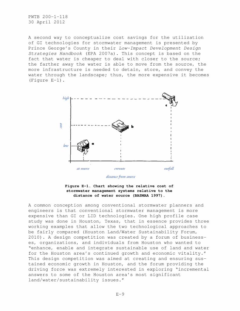
PWTB 200-1-118 30 April 2012
E-9
A second way to conceptualize cost savings for the utilization of GI technologies for stormwater management is presented by Prince George’s County in their Low-Impact Development Design Strategies Handbook (EPA 2007a). This concept is based on the fact that water is cheaper to deal with closer to the source; the farther away the water is able to move from the source, the more infrastructure is needed to detain, store, and convey the water through the landscape; thus, the more expensive it becomes (Figure E-1).
Figure E-1. Chart showing the relative cost of stormwater management systems relative to the
distance of water source (BASMAA 1997).
A common conception among conventional stormwater planners and engineers is that conventional stormwater management is more expensive than GI or LID technologies. One high profile case study was done in Houston, Texas, that in essence provides three working examples that allow the two technological approaches to be fairly compared (Houston Land/Water Sustainability Forum, 2010). A design competition was created by a forum of business-es, organizations, and individuals from Houston who wanted to “enhance, enable and integrate sustainable use of land and water for the Houston area’s continued growth and economic vitality.” This design competition was aimed at creating and ensuring sus-tained economic growth in Houston, and the forum providing the driving force was extremely interested in exploring “incremental answers to some of the Houston area’s most significant land/water/sustainability issues.”

PWTB 200-1-118 30 April 2012
E-10
With their goals in mind, the forum recognized that LID had the potential to provide sustainable infrastructure to support their business and economic aims. With a goal of accelerating the adoption, adaptation, and implementation of LID as well as other sustainable development practices, they held a $15,000 design competition. Each design team was required to include a licensed civil engineer, architect, and landscape architect. The three projects to choose from included: a Green Roadway, an Urban Redevelopment, and a Suburban Residential area. These were all real projects with build potential in a high-profile competi-tion, so designers around Houston and beyond were motivated to create feasible and quality designs.
An aim of the design competition was to ensure that stormwater was dealt with using LID; the contestants had to prove their proposal primarily used LID to match or exceed conventional development standards for 5-year, 10-year, and 100-year storms. Another requirement was that the LID design cost less than what the conventional stormwater treatment alternative would have cost.
With 22 design teams (comprised of 49 firms) entering the compe-tition, and a jury panel including an EPA representative and other Houston area leaders in development, construction, politi-cal and civic communities, this high profile design competition provides a solid case study of GI benefits in a geographic re-gion where this type of infrastructure traditionally has been under-utilized.
The Chief of EPA’s Nonpoint Source Control Branch summarized the two main outcomes of the Houston LID competition (Weitman, 2010). The first proved that LID practices can manage all or most storm events onsite, completely replacing traditional stormwater infrastructure.* The second outcome showed LID is cheaper than or as cheap as conventional stormwater management with the benefits of less maintenance and added-values of aes-thetics and water quality. The competition’s conclusion illus-trated the substantial cost savings, showing people from all business sectors that LID was an effective strategy and cost-efficient solution providing significant long-term benefits for the Houston area. In particular, the exercise proved to engi-
* In this instance, LID technologies replaced conventional systems entirely. However, since GI/LID/LI are dependent on environmental contexts of soils, infiltration, and site properties, this may not be entirely possible on all sites.

PWTB 200-1-118 30 April 2012
E-11
neers and businesses the benefits of using LID and GI strategies for stormwater management.*
If a project shows indications that implementing a GI technique may actually be more expensive, the project managers should prepare a life-cycle cost analysis. While GI technologies might initially be expensive, over the life of the structure the en-hanced environmental and aesthetic benefits gained from GI usu-ally outweigh the lower initial cost of a conventional stormwater system.
Implementation Process
The implementation process for either installing or retrofitting existing infrastructure to GI and either LID or LI is similar to the conventional method for stormwater management systems in-stallations. Water data must be obtained and used to calculate storm events and design for capacities. GI aims to treat all stormwater onsite using the natural features of the site. To begin planning a GI system, a site’s natural features must be analyzed to determine the most effective strategy for implement-ing GI. This section will outline the general approach and de-sign considerations, obstacles, and driving factors that will contribute to successfully implementing GI for stormwater man-agement.
Many resources are available in the form of books, magazine articles, reports, design guides, and online publications that identify multiple approaches and stepwise instructions on how to plan for and implement GI stormwater management systems. For this PWTB, an integrated implementation process (Figure E-2) has been compiled from various references. The process highlights the technical capabilities and actions that must be taken as well as the necessary concepts and base conditions that are necessary for a successful project.
* More details about the competition, associated sponsors, and business en-dorsements can be found at http://www.houstonlwsforum.org/designCompetition/. The letter of support written by the EPA Branch Chief, Dov Weitman, can be found at: http://www.mayorsinnovation.org/pdf/6MIC.pdf
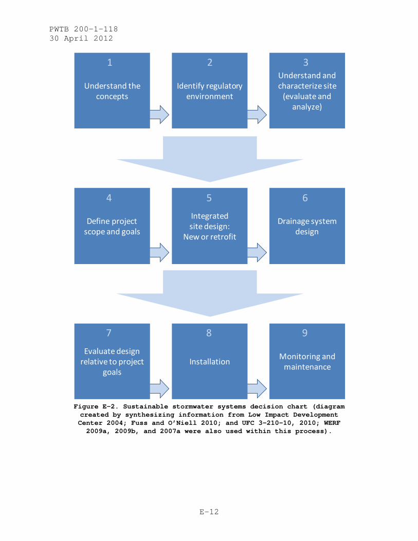
PWTB 200-1-118 30 April 2012
E-12
Figure E-2. Sustainable stormwater systems decision chart (diagram created by synthesizing information from Low Impact Development Center 2004; Fuss and O’Niell 2010; and UFC 3-210-10, 2010; WERF 2009a, 2009b, and 2007a were also used within this process).
Understand the concepts
Identify regulatory environment
Understand and characterize site
(evaluate and analyze)
Define project scope and goals
Integrated site design:
New or retrofit
Drainage system design
Evaluate design relative to project
goalsInstallation Monitoring and
maintenance
1 2 3
4 5 6
7 8 9
PWTB 200-1-118 30 April 2012
E-13
This section explains the nine steps just presented as a flow chart in Figure E-2.
1 - Understand the concepts. • every site is a watershed • start at the source • think small • keep it simple • be prepared to integrate various solutions
2 - Identify regulatory environment.
• planning opportunities and limitations • site-specific zoning or development restraints • federal (or state) development policies, regulation,
legislation • local design guides • incentives or subsidies • certification programs
3 - Understand and characterize the site (evaluate and ana-lyze).
• soils o hydrologic soil groups (Figure E-3)
• current site hydrologic condition (Figure E-4)* o subsurface water flow o water table levels o aquifer presence and plume activity o natural processes (infiltration areas, ponding,
ephemeral or seasonal watercourses, permanent water-courses, infiltration pathways)
o point-source pathways
• predevelopment hydrologic condition and processes
• environmental site conditions (e.g., slope, aspect, land cover)
* The LID design charts referenced (i.e., Chart A, Chart B, Chart C) refer to design charts that the Low Impact Development Center created for the Prince George’s County Manual, Prince George's County Maryland Department of Envi-ronmental Resources Programs and Planning Division (PGDER) at 301-883-5833). This also serves as the basis for the LID Hydrology National Manual created by the Low Impact Development Center. In the charts, CN is the abbreviation for the runoff curve number; Tc is the abbreviation for the time of concen-tration.
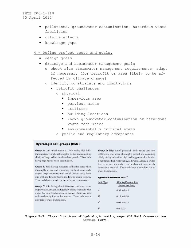
PWTB 200-1-118 30 April 2012
E-14
• pollutants, groundwater contamination, hazardous waste facilities
• offsite effects
• knowledge gaps
4 - Define project scope and goals.
• design goals
• drainage and stormwater management goals o check site stormwater management requirements; adapt
if necessary (for retrofit or area likely to be af-fected by climate change)
o identify constraints and limitations retrofit challenges
o physical impervious area pervious areas utilities building locations known groundwater contamination or hazardous
waste facilities environmentally critical areas
o public and regulatory acceptance
Figure E-3. Classifications of hydrologic soil groups (US Soil Conservation
Service 1987).
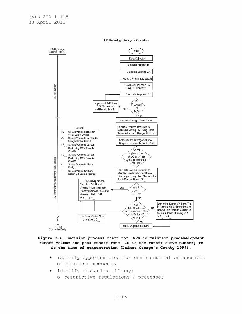
PWTB 200-1-118 30 April 2012
E-15
Figure E-4. Decision process chart for IMPs to maintain predevelopment runoff volume and peak runoff rate. CN is the runoff curve number; Tc
is the time of concentration (Prince George’s County 1999).
• identify opportunities for environmental enhancement of site and community
• identify obstacles (if any) o restrictive regulations / processes

PWTB 200-1-118 30 April 2012
E-16
o internal or organizational resistance o community resistance o lack of technical knowledge o lack of resources o environmental complications
5 - Integrated site design: New or retrofit?
• initial site evaluation (retrofit) o evaluate site layout o evaluate current stormwater management system
• define development envelope and protected areas o site fingerprinting to eliminate unnecessary
negative impacts on site o runoff reduction optional
• design process o After data collection and site analysis, for the
design process, hydrologic computations must be completed to quantify the parameters for each stormwater management technology that will be installed. The following stepwise process outline has been adapted from the EPA’s website and is adapted and presented here to give an idea of the design process and calculations involved (Prince George’s County 1999). This is not meant to be a detailed guide, as licensed designers or engineers will be necessarily involved during site design calculations; however, this should provide a good procedural reference for interested parties.
o For hydrologic equations and computation worksheets, as well as very detailed explanations into the design process behind creating LID stormwater management systems, the following two references will provide more detailed information for “small watersheds” such as what is created and used within GI/LID/LI technologies. Natural Resources Conservation Service (NRCS)
1986. Urban Hydrology for Small Watersheds. Technical Release 55. (See Appendix K.)

PWTB 200-1-118 30 April 2012
E-17
NRCS 1997. National Engineering Handbook, Part 630 – Hydrology (previously NEH-4). (See Appendix K.)
6 - Drainage system design • minimize “directly connected” impervious areas • maximize permeability • treat drainage as a design element when possible • system elements
o identify applicable GI/LID/LI technologies o choose technologies appropriate for the site
environmental conditions and setting/site context o choose feasible technologies that can be appropri-
ately maintained with available resources • water quality management
o goals o water quality volume
7 - Evaluate design relative to project goals.
• Re-evaluate site and drainage design relative to runoff volume, peak runoff rate, flow frequency and duration, and water quality. Check calculations for runoff, detention and retention, and infiltration to ensure GI stormwater management goals are being met.
8 – Installation. • As in any construction project, qualified contractors
should be hired for the job. Specialized GI/LID/LI technologies require prior knowledge of techniques, common pitfalls, and knowledge of hydrologic processes in order to ensure that the site design is installed correctly.
• Many resources are available to assist user communi-ties in evaluating LID technologies. Some key refer-ences are listed within this section. For further information, Appendix K lists references for this PWTB or the POC listed on page 6 of this PWTB may be con-tacted for follow-up discussions.
9 - Monitoring and maintenance. • Maintenance is one aspect of GI installations that can
make or break the success of the project. Low levels of maintenance are required, and if that maintenance is successful, the GI stormwater management system can

PWTB 200-1-118 30 April 2012
E-18
be expected to meet its life-cycle expectation at full function.
• If the low-level maintenance tasks are not fulfilled, the system will likely falter, repairs will be re-quired, and unexpected costs will be incurred. This situation should be avoided to get the most out of the GI design and maintain the sustainability of the site.
• Maintenance requirements typically consist of the fol-lowing activities: o landscaping and vegetation management o sediment and accumulated pollutant removal o structural repairs to bmp components o regular inspections o restoration and/or rejuvenation of bmp components
(i.e., scarifying infiltration beds) o repair of inlet and outlet structures and other bmp
amenities and flow control structures o waterproofing and/or bmp liner replacement/repair
• Maintenance activities and monitoring activities come hand in hand, as monitoring can provide feedback on whether or how to adjust maintenance schedules and tasks relative to owner needs. Life-cycle costs can be evaluated, and specifications can be developed to cre-ate a more efficient, integrated, and effective maintenance program.
• Table E-2 presents a sample maintenance schedule for reference.
• Monitoring GI stormwater systems is recommended. A post-installation monitoring program does not have to be extensive, but is useful to ensure that the tech-nologies are working and performing to their full po-tential. With a monitoring system in place, technologies can be periodically evaluated (allowing for design revisions if necessary), water quality mon-itored, and flood data collected (e.g., for land and property insurance purposes). The stormwater system monitoring data also can be utilized to inform future developments and site evaluations, as weather data and resulting site processes can serve as data caches for similar development situations (although calculations should always be performed site-specifically to ensure that the drainage designs are appropriate and well-suited for use onsite.
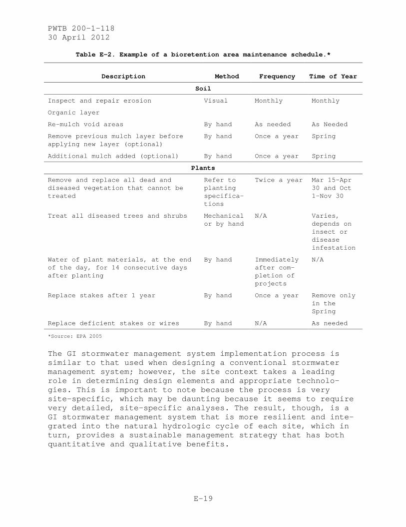
PWTB 200-1-118 30 April 2012
E-19
Table E-2. Example of a bioretention area maintenance schedule.*
Description Method Frequency Time of Year
Soil
Inspect and repair erosion Visual Monthly Monthly
Organic layer
Re-mulch void areas By hand As needed As Needed
Remove previous mulch layer before applying new layer (optional)
By hand Once a year Spring
Additional mulch added (optional) By hand Once a year Spring
Plants
Remove and replace all dead and diseased vegetation that cannot be treated
Refer to planting specifica-tions
Twice a year Mar 15–Apr 30 and Oct 1–Nov 30
Treat all diseased trees and shrubs Mechanical or by hand
N/A Varies, depends on insect or disease infestation
Water of plant materials, at the end of the day, for 14 consecutive days after planting
By hand Immediately after com-pletion of projects
N/A
Replace stakes after 1 year By hand Once a year Remove only in the Spring
Replace deficient stakes or wires By hand N/A As needed
*Source: EPA 2005
The GI stormwater management system implementation process is similar to that used when designing a conventional stormwater management system; however, the site context takes a leading role in determining design elements and appropriate technolo-gies. This is important to note because the process is very site-specific, which may be daunting because it seems to require very detailed, site-specific analyses. The result, though, is a GI stormwater management system that is more resilient and inte-grated into the natural hydrologic cycle of each site, which in turn, provides a sustainable management strategy that has both quantitative and qualitative benefits.

PWTB 200-1-118 30 April 2012
F-1
APPENDIX F
ADAPTING HISTORIC DISTRICTS
In the case of historic landscapes, adverse effects of those technologies could include changing the spatial organization of buildings, altering the transportation networks, altering archi-tectural styling, and adding incompatible vegetation. However, by understanding a historic district’s conditions and how the site fits into the area’s hydrologic cycle, sustainable storm-water management can be integrated into the existing environmen-tal fabric.
Incorporating GI into existing conditions is a well-discussed topic, but few guidelines have been established regarding retro-fitting a designated historic district on a military installa-tion with sustainable technologies. This section uses case studies of how sustainable stormwater projects are currently being addressed at several Army installations in different US ecological zones. These studies discuss sustainable strategies that have already been implemented in historic districts, how managers navigate preservation issues, and possible areas of small- to large-scale deployment of sustainable stormwater sys-tems through material choices, vegetation options, and landform modifications.
Fort Leavenworth, Kansas
Fort Leavenworth is situated on a bluff overlooking the Missouri River. Because of its location and environmental conditions, drainage is not much of a problem. Runoff has a variety of courses, many of which are through woodlands. As a result, adapting landscapes is not prioritized in sustainability deci-sions. However, the landscape approach that cultural and natural resource managers take is to change as little as possible and to enhance systems that are already working.
Effective examples of water management at Fort Leavenworth are integrating parking lots with retention features, pavers, and terracing. While terracing was not original to the historic district, careful planning and consultation with the Kansas SHPO resulted in no adverse effect to the historic district. This coordinated approach ensures cost-effectiveness and Section 106 compliance.
Fort Leavenworth’s approach is based on its buildings management strategy, which is to inventory the building using a Historic
PWTB 200-1-118 30 April 2012
F-2
Structures Report, analyze what new technologies need to be incorporated, and find ways to adapt and reuse old systems. Everything they implement contributes to the character of the district and, if there is any question about the suitability of a project, managers ensure the undertakings are suitable.
Fort Leavenworth does not have a comprehensive stormwater man-agement plan. Instead, managers try to incorporate LID and sus-tainable technologies into appropriate projects. By working closely with the SHPO and involving all stakeholders in the early stages of project planning, Fort Leavenworth is successful at adapting their historic district to the Army’s sustainability requirements. In the historic district, the installation has just completed a LEED Gold renovation of the former hospital. A rain garden was constructed near the renovated facility’s park-ing lot for stormwater sequestration. Although implemented with approval from the SHPO, soil conditions were unsuitable for it to function properly and it was removed.
Fort Huachuca, Arizona
According to Fort Huachuca cultural resources personnel (Tagg 2011, personal communication), the historic district’s storm-water system is failing. The current system is overloaded during major rain events because the historic district is located in a valley where the terrain concentrates water into low areas (Figure F-1 and Figure F-2). The result is flooded streets, parking lots, and basements. The current, conventional system needs to be replaced to accommodate and manage these types of rain events. The problem is the current system is historic — built in the 1930s as a Works Progress Administration (WPA) project. The system is representative of WPA stone and ditch work; redoing it would compromise its historic characteristics. Because the stonework and the entire stormwater system cannot be altered, managing the stormwater runoff has to occur before the water reaches the historic district. Cultural resource and water managers have to collaborate on systems that will not detract from the historic views of the district but will manage large amounts of water.
In this case, the conventional water system should be retained in the historic district, but sustainable systems used to manag-ing flooding in the district. To this effect, sustainable storm-water management systems are being implemented adjacent to the district’s boundaries. Stormwater management systems in the historic district are also limited to the small size and com-pactness of the district. Therefore, the physical constraints of

PWTB 200-1-118 30 April 2012
F-3
the district limit the feasibility of LID in all but small-scale interventions. Implementing materials like permeable pavement into the district, however, would have a positive effect on their water problems.
Figure F-1. Aerial view of Fort Huachuca, 1924 (Fort Huachuca
Cultural Resources).

PWTB 200-1-118 30 April 2012
F-4
Figure F-2. Aerial view of Fort Huachuca historic district,
1980s (Fort Huachuca Cultural Resources).
Joint Base Lewis-McChord, Washington
At Fort Lewis, three LID projects were proposed for the historic district and planned in coordination with the Washington SHPO. The first project was redoing parking lots in front of storage buildings. The storage buildings were originally stables and lacked vegetation. The proposed parking lot renovations would improve the lot by incorporating swales at the boundaries in place of curbs. Additionally, planters and xeriscaping were planned to break up the lot and make it more visually appealing. After some negotiations with SHPO, the plan was finally ap-proved. However, it was never constructed because a larger pro-ject was proposed for the area.
The larger project was to widen the street along the storage area parking lot. While not specifically a sustainable plan, the proposal would incorporate street trees on both sides and a divider with trees down the middle of the boulevard. This pro-ject was more in keeping with the historic master plan of the cantonment. The plan for Fort Lewis was based on the Quartermas-ter Corps standardized installation designs by city planner George B. Ford. Standardized plans in the early 1900s emphasized street trees and axial alignment.

PWTB 200-1-118 30 April 2012
F-5
The third LID project was in response to increasing development needs. Fort Lewis planned to adapt a former industrial area into a new neighborhood. In addition to providing housing, the neigh-borhood would form a small business center in the historic dis-trict by providing some dining and shopping options. The area was planned to be pedestrian-friendly with reoriented parking, adding walking paths, and installing swales and rain gardens. Historically, stables and industrial areas were sparsely vege-tated, utilitarian places. Converting the area to a neighborhood presented many challenging obstacles. By incorporating the SHPO in the early stages of planning, Fort Lewis could approve a plan that met goals for reuse and sustainability while preserving the overall historic integrity and complying with NHPA requirements.
Fort Knox, Kentucky
Fort Knox covers an area of 169 square miles (~438 square kilo-meters) along the Ohio River. The terrain is rolling upland in the central and western parts and rounded steep-sided ridges in the eastern portion. Soils are claypan and silty and are highly fertile. Underlying them are fossiliferous limestone, dolostone, and shale. The result is karst topography characterized by sink-holes, caves, and disappearing streams draining to underground rivers. These conditions, combined with fairly high annual pre-cipitation rates, result in the opportunity for water to pond in low-lying areas during heavy rain events. In the historic dis-trict, the conventional stormwater management system is able to handle the runoff from most rain events.
The historic district at Fort Knox was designed according to early twentieth-century city planning ideas. The district re-flects the standardized military plans with its unified archi-tectural style, rectilinear street pattern organized around a central ceremonial open space, streets lined with trees, and minimal vegetation. The district retains its historic integrity and, while strategies for sustainability are welcome, sustaina-ble systems are hard to implement in the district. This diffi-culty is caused mostly by the lack of a master plan accounting for historic characteristics while proposing opportunities for change.
In the case of implementing sustainable stormwater management systems, the district has few open spaces available for growth and would have to rely on small-scale interventions. Opportuni-ties for small-scale green stormwater systems exist in the resi-dential areas of the district where residents can personalize their yards. Rain gardens that take advantage of low areas could

PWTB 200-1-118 30 April 2012
F-6
be constructed according to historic district guidelines and housing authority regulations, while passive irrigation tech-niques could also be incorporated into residential designs. Although parking is somewhat limited in the historic district, permeable paving in parking lots would slow runoff and allow for infiltration. Even though Fort Knox does not have a sustainable master plan, there are still opportunities to begin incorporat-ing sustainable stormwater strategies in the historic district.

PWTB 200-1-118 30 April 2012
APPENDIX G
MATRIX OF GREEN INFRASTRUCTURE TECHNOLOGIES AND HISTORIC DISTRICT COMPATIBILITY
In this appendix, Table G-1 outlines a matrix of GI technologies and compares a variety of factors, including historic district compatibility.

* 1 if originally used in cantonment; 2 if it retains the look and feel of original material; 3 if integrated into the historic context; 4 if outside the historic core; 5 if out-of-sight
PWTB 200-1-118
30 April 2012
G-2
Table G-1. Matrix comparing green infrastructure technologies with a variety of factors, including historic district compatibility.
Ref. Available Technology Historic Compatible*
Perme-able
PURPOSE REQUIREMENTS
Transport Deten- tion
Storage Filtra-tion
Infil- tration
Init. Cost
Maint.
G-2 Concrete pipe Yes - - - - - -
G-4 Drainage ditch Yes / -
G-5 Dry well Yes / -
G-6 Foundation or side-of-building plantings Yes - / -
G-8 Vertical plantings (greenwalls) Yes1,2 / - / - / - / - -
G-10 Natural creek Yes / - / -
G-12 Natural vegetation Yes / - / - / - / -
G-13 Soakaway trench Yes
G-14 Stone / rip rap channel Yes / - / - / - / - / - / -
G-16 Surface landscaping Yes / - / - / - / -
G-17 Corrugated metal - vault / cistern Yes5 - - - -
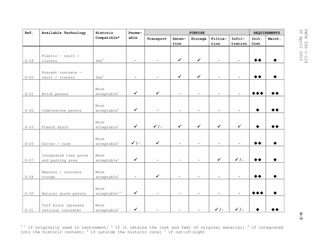
* 1 if originally used in cantonment; 2 if it retains the look and feel of original material; 3 if integrated into the historic context; 4 if outside the historic core; 5 if out-of-sight
PWTB 200-1-118
30 April 2012
G-3
Ref. Available Technology Historic Compatible*
Perme-able
PURPOSE REQUIREMENTS
Transport Deten- tion
Storage Filtra-tion
Infil- tration
Init. Cost
Maint.
G-18 Plastic - vault / cistern Yes5 - - - -
G-20 Precast concrete - vault / cistern Yes5 - - - -
G-21 Brick pavers More acceptable1 - - - -
G-22 Cobblestone pavers More acceptable1 - - - - -
G-23 French drain More acceptable1 / -
G-25 Gutter / curb More acceptable1 / - - - - -
G-27 Integrated tree grove and parking area
More acceptable1 - - - / -
G-28 Masonry / concrete trough
More acceptable1 - - - - -
G-30 Natural stone pavers More acceptable1,2 - - - - -
G-31 Turf block (grassed cellular concrete)
More acceptable1 - - - / - / -
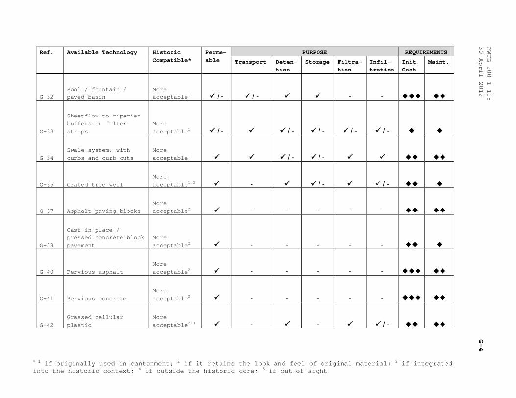
* 1 if originally used in cantonment; 2 if it retains the look and feel of original material; 3 if integrated into the historic context; 4 if outside the historic core; 5 if out-of-sight
PWTB 200-1-118
30 April 2012
G-4
Ref. Available Technology Historic Compatible*
Perme-able
PURPOSE REQUIREMENTS
Transport Deten- tion
Storage Filtra-tion
Infil- tration
Init. Cost
Maint.
G-32 Pool / fountain / paved basin
More acceptable1 / - / - - -
G-33
Sheetflow to riparian buffers or filter strips
More acceptable1 / - / - / - / - / -
G-34 Swale system, with curbs and curb cuts
More acceptable1 / - / -
G-35 Grated tree well More acceptable1,3 - / - / -
G-37 Asphalt paving blocks More acceptable2 - - - - -
G-38
Cast-in-place / pressed concrete block pavement
More acceptable2 - - - - -
G-40 Pervious asphalt More acceptable2 - - - - -
G-41 Pervious concrete More acceptable2 - - - - -
G-42 Grassed cellular plastic
More acceptable2,3 - - / -
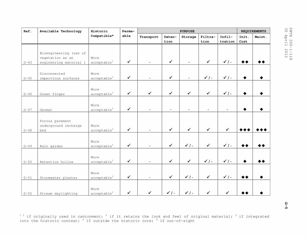
* 1 if originally used in cantonment; 2 if it retains the look and feel of original material; 3 if integrated into the historic context; 4 if outside the historic core; 5 if out-of-sight
PWTB 200-1-118
30 April 2012
G-5
Ref. Available Technology Historic Compatible*
Perme-able
PURPOSE REQUIREMENTS
Transport Deten- tion
Storage Filtra-tion
Infil- tration
Init. Cost
Maint.
G-43
Bioengineering (use of vegetation as an engineering material )
More acceptable3 - - / -
G-45 Disconnected impervious surfaces
More acceptable3 - - / - / -
G-46 Green finger More acceptable3 / -
G-47 Geomat More acceptable3 - - - - -
G-48
Porous pavement underground recharge bed
More acceptable3 -
G-49 Rain garden More acceptable3 - / - / -
G-50 Retention hollow More acceptable3 - / - / -
G-51 Stormwater planter More acceptable3 - / - / -
G-52 Stream daylighting More acceptable3 / - / -
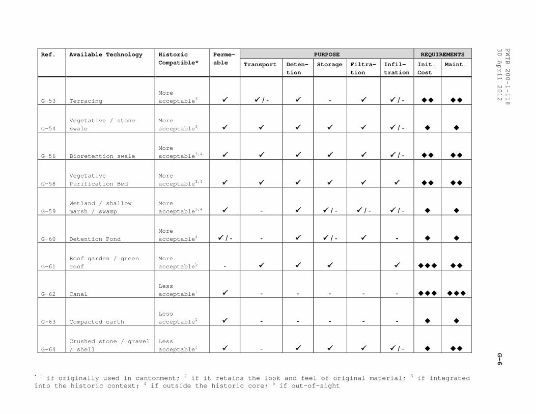
* 1 if originally used in cantonment; 2 if it retains the look and feel of original material; 3 if integrated into the historic context; 4 if outside the historic core; 5 if out-of-sight
PWTB 200-1-118
30 April 2012
G-6
Ref. Available Technology Historic Compatible*
Perme-able
PURPOSE REQUIREMENTS
Transport Deten- tion
Storage Filtra-tion
Infil- tration
Init. Cost
Maint.
G-53 Terracing More acceptable3 / - - / -
G-54 Vegetative / stone swale
More acceptable3 / -
G-56 Bioretention swale More acceptable3,4 / -
G-58 Vegetative Purification Bed
More acceptable3,4
G-59 Wetland / shallow marsh / swamp
More acceptable3,4 - / - / - / -
G-60 Detention Pond More acceptable4 / - - / - -
G-61 Roof garden / green roof
More acceptable5 -
G-62 Canal Less acceptable1 - - - - -
G-63 Compacted earth Less acceptable1 - - - - -
G-64 Crushed stone / gravel / shell
Less acceptable1 - / -
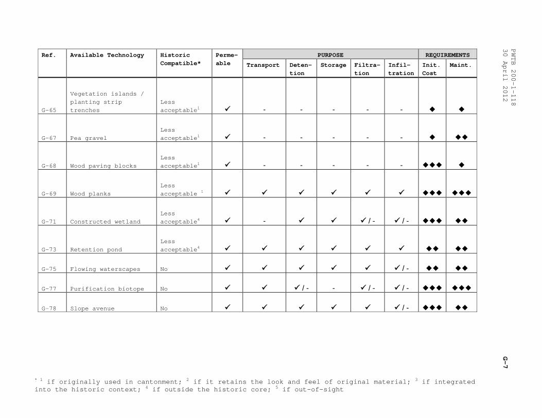
* 1 if originally used in cantonment; 2 if it retains the look and feel of original material; 3 if integrated into the historic context; 4 if outside the historic core; 5 if out-of-sight
PWTB 200-1-118
30 April 2012
G-7
Ref. Available Technology Historic Compatible*
Perme-able
PURPOSE REQUIREMENTS
Transport Deten- tion
Storage Filtra-tion
Infil- tration
Init. Cost
Maint.
G-65
Vegetation islands / planting strip trenches
Less acceptable1 - - - - -
G-67 Pea gravel Less acceptable1 - - - - -
G-68 Wood paving blocks Less acceptable1 - - - - -
G-69 Wood planks Less acceptable 1
G-71 Constructed wetland Less acceptable4 - / - / -
G-73 Retention pond Less acceptable4
G-75 Flowing waterscapes No / -
G-77 Purification biotope No / - - / - / -
G-78 Slope avenue No / -

PWTB 200-1-118 30 April 2012
H-1
APPENDIX H
CATALOG OF GREEN INFRASTRUCTURE TECHNOLOGIES
Please see the following pages of this appendix and Figure H-1 —Figure H-87 for more information about GI infrastructure and its applications.
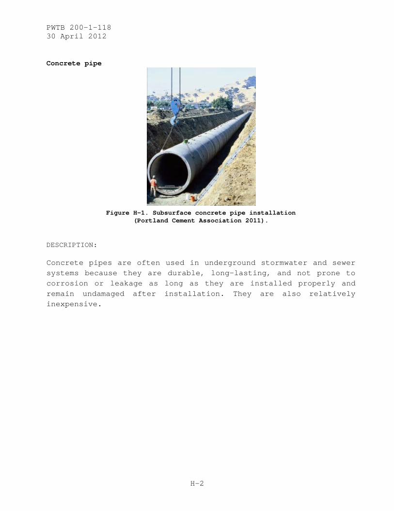
PWTB 200-1-118 30 April 2012
H-2
Concrete pipe
Figure H-1. Subsurface concrete pipe installation
(Portland Cement Association 2011).
DESCRIPTION:
Concrete pipes are often used in underground stormwater and sewer systems because they are durable, long-lasting, and not prone to corrosion or leakage as long as they are installed properly and remain undamaged after installation. They are also relatively inexpensive.
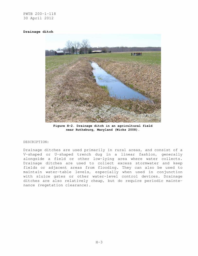
PWTB 200-1-118 30 April 2012
H-3
Drainage ditch
Figure H-2. Drainage ditch in an agricultural field
near Ruthsburg, Maryland (Wicks 2008).
DESCRIPTION:
Drainage ditches are used primarily in rural areas, and consist of a V-shaped or U-shaped trench dug in a linear fashion, generally alongside a field or other low-lying area where water collects. Drainage ditches are used to collect excess stormwater and keep fields or adjacent areas from flooding. They can also be used to maintain water-table levels, especially when used in conjunction with sluice gates or other water-level control devices. Drainage ditches are also relatively cheap, but do require periodic mainte-nance (vegetation clearance).
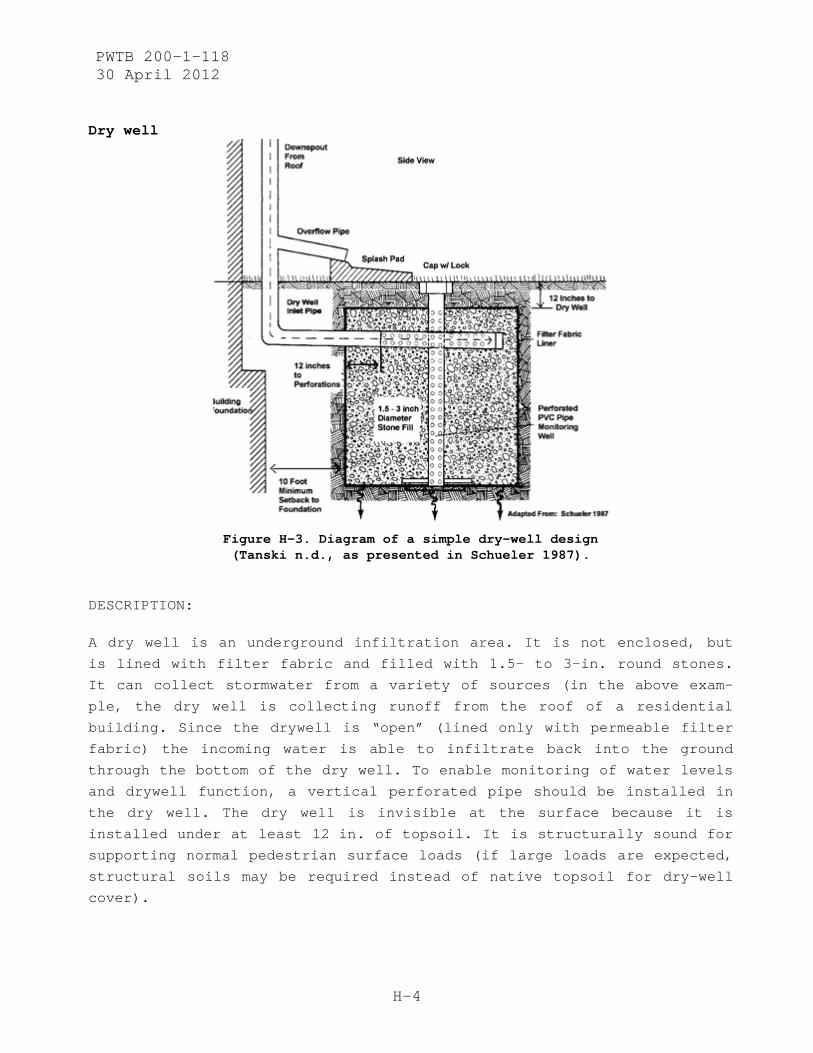
PWTB 200-1-118 30 April 2012
H-4
Dry well
Figure H-3. Diagram of a simple dry-well design (Tanski n.d., as presented in Schueler 1987).
DESCRIPTION:
A dry well is an underground infiltration area. It is not enclosed, but
is lined with filter fabric and filled with 1.5- to 3-in. round stones.
It can collect stormwater from a variety of sources (in the above exam-
ple, the dry well is collecting runoff from the roof of a residential
building. Since the drywell is “open” (lined only with permeable filter
fabric) the incoming water is able to infiltrate back into the ground
through the bottom of the dry well. To enable monitoring of water levels
and drywell function, a vertical perforated pipe should be installed in
the dry well. The dry well is invisible at the surface because it is
installed under at least 12 in. of topsoil. It is structurally sound for
supporting normal pedestrian surface loads (if large loads are expected,
structural soils may be required instead of native topsoil for dry-well
cover).
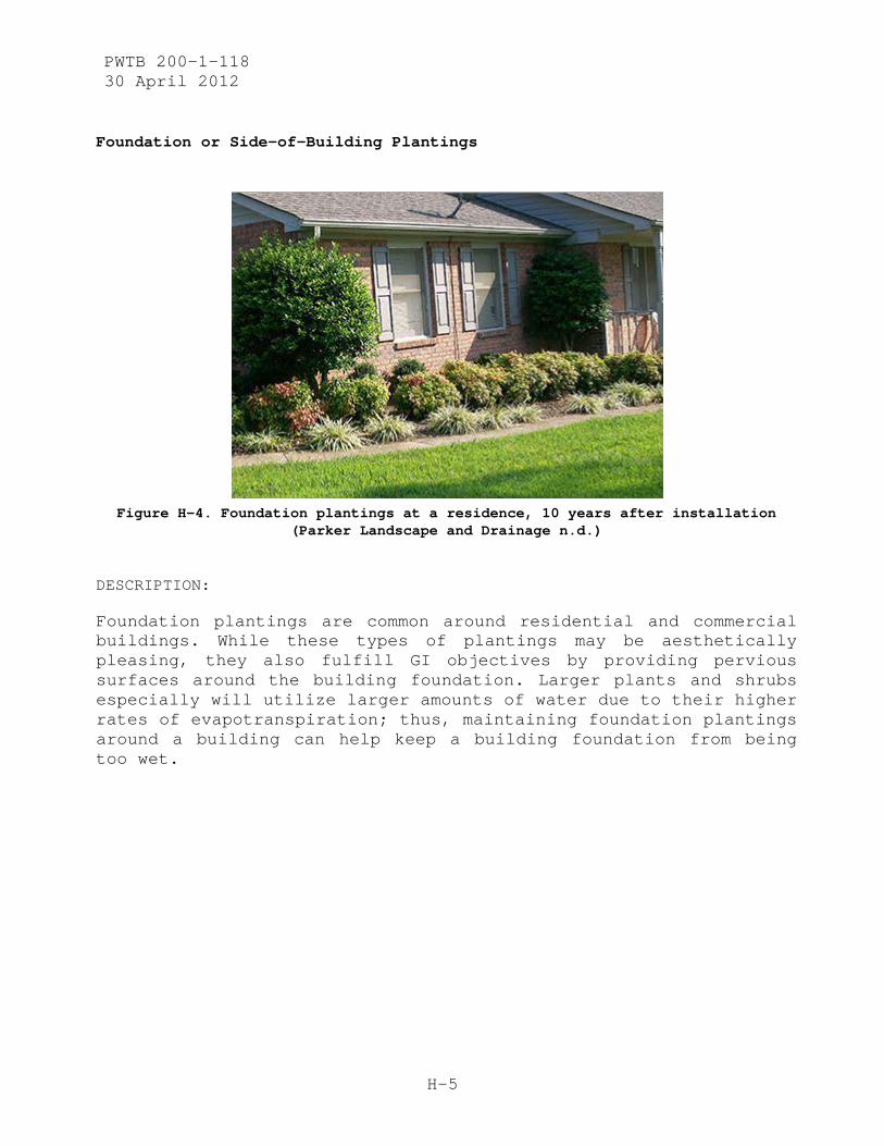
PWTB 200-1-118 30 April 2012
H-5
Foundation or Side-of-Building Plantings
Figure H-4. Foundation plantings at a residence, 10 years after installation
(Parker Landscape and Drainage n.d.)
DESCRIPTION:
Foundation plantings are common around residential and commercial buildings. While these types of plantings may be aesthetically pleasing, they also fulfill GI objectives by providing pervious surfaces around the building foundation. Larger plants and shrubs especially will utilize larger amounts of water due to their higher rates of evapotranspiration; thus, maintaining foundation plantings around a building can help keep a building foundation from being too wet.

PWTB 200-1-118 30 April 2012
H-6
Vertical Plantings (Greenwalls)
Figure H-5. Marché des Halles in Avignon (TheGrowSpot.com 2007).
DESCRIPTION:
Greenwalls are gaining in popularity. They can be used to provide added insulation and weather protection to buildings while providing aesthetically pleasing displays of greenery. There are many health and quality-of-life benefits to greenwalls, whether installed on external building facades or as indoor greenwalls. Greenwalls can be maintained by rainwater collected from roof runoff or even runoff from impervious hardscaped areas around the building, thus lessening overflow runoff volumes offsite.
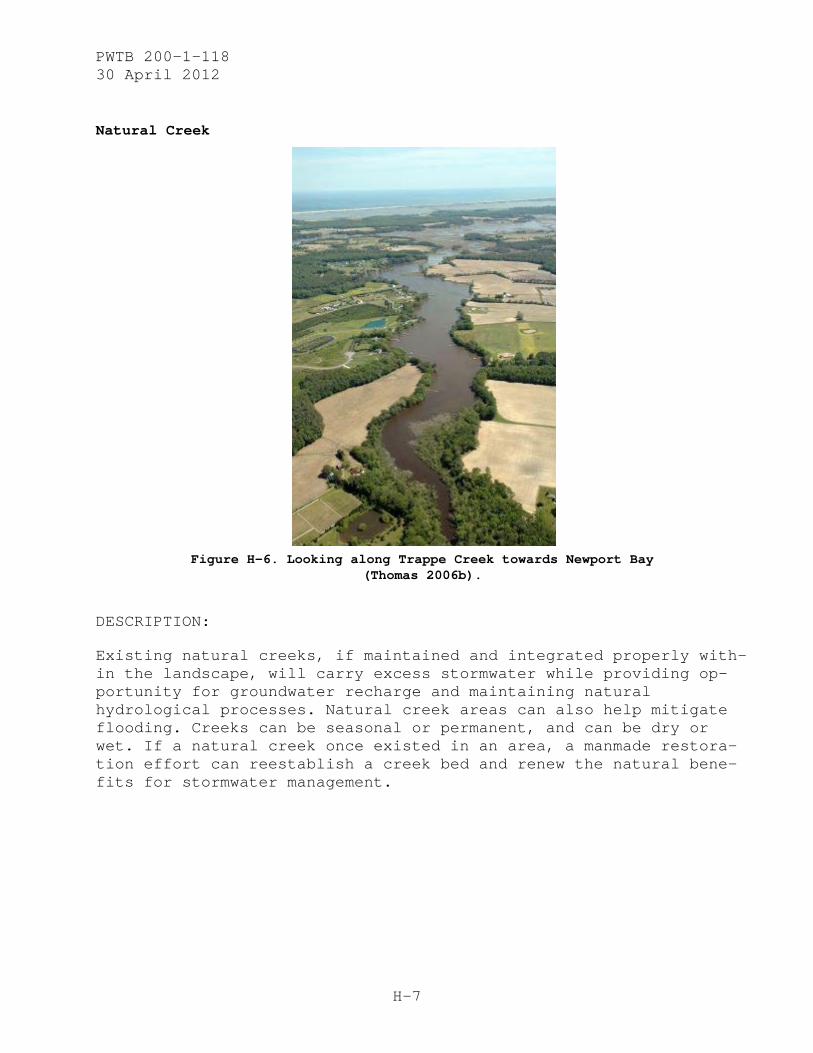
PWTB 200-1-118 30 April 2012
H-7
Natural Creek
Figure H-6. Looking along Trappe Creek towards Newport Bay
(Thomas 2006b).
DESCRIPTION:
Existing natural creeks, if maintained and integrated properly with-in the landscape, will carry excess stormwater while providing op-portunity for groundwater recharge and maintaining natural hydrological processes. Natural creek areas can also help mitigate flooding. Creeks can be seasonal or permanent, and can be dry or wet. If a natural creek once existed in an area, a manmade restora-tion effort can reestablish a creek bed and renew the natural bene-fits for stormwater management.
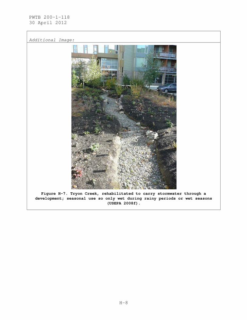
PWTB 200-1-118 30 April 2012
H-8
Additional Image:
Figure H-7. Tryon Creek, rehabilitated to carry stormwater through a
development; seasonal use so only wet during rainy periods or wet seasons (USEPA 2008f).
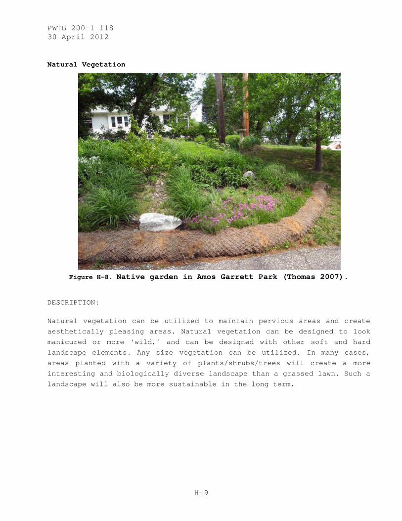
PWTB 200-1-118 30 April 2012
H-9
Natural Vegetation
Figure H-8. Native garden in Amos Garrett Park (Thomas 2007).
DESCRIPTION:
Natural vegetation can be utilized to maintain pervious areas and create
aesthetically pleasing areas. Natural vegetation can be designed to look
manicured or more ‘wild,’ and can be designed with other soft and hard
landscape elements. Any size vegetation can be utilized. In many cases,
areas planted with a variety of plants/shrubs/trees will create a more
interesting and biologically diverse landscape than a grassed lawn. Such a
landscape will also be more sustainable in the long term.
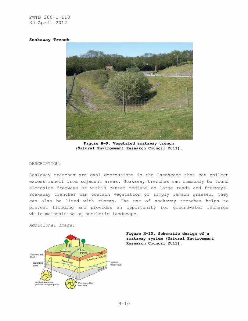
PWTB 200-1-118 30 April 2012
H-10
Soakaway Trench
Figure H-9. Vegetated soakaway trench
(Natural Environment Research Council 2011).
DESCRIPTION:
Soakaway trenches are oval depressions in the landscape that can collect
excess runoff from adjacent areas. Soakaway trenches can commonly be found
alongside freeways or within center medians on large roads and freeways.
Soakaway trenches can contain vegetation or simply remain grassed. They
can also be lined with riprap. The use of soakaway trenches helps to
prevent flooding and provides an opportunity for groundwater recharge
while maintaining an aesthetic landscape.
Additional Image:
Figure H-10. Schematic design of a soakaway system (Natural Environment Research Council 2011).
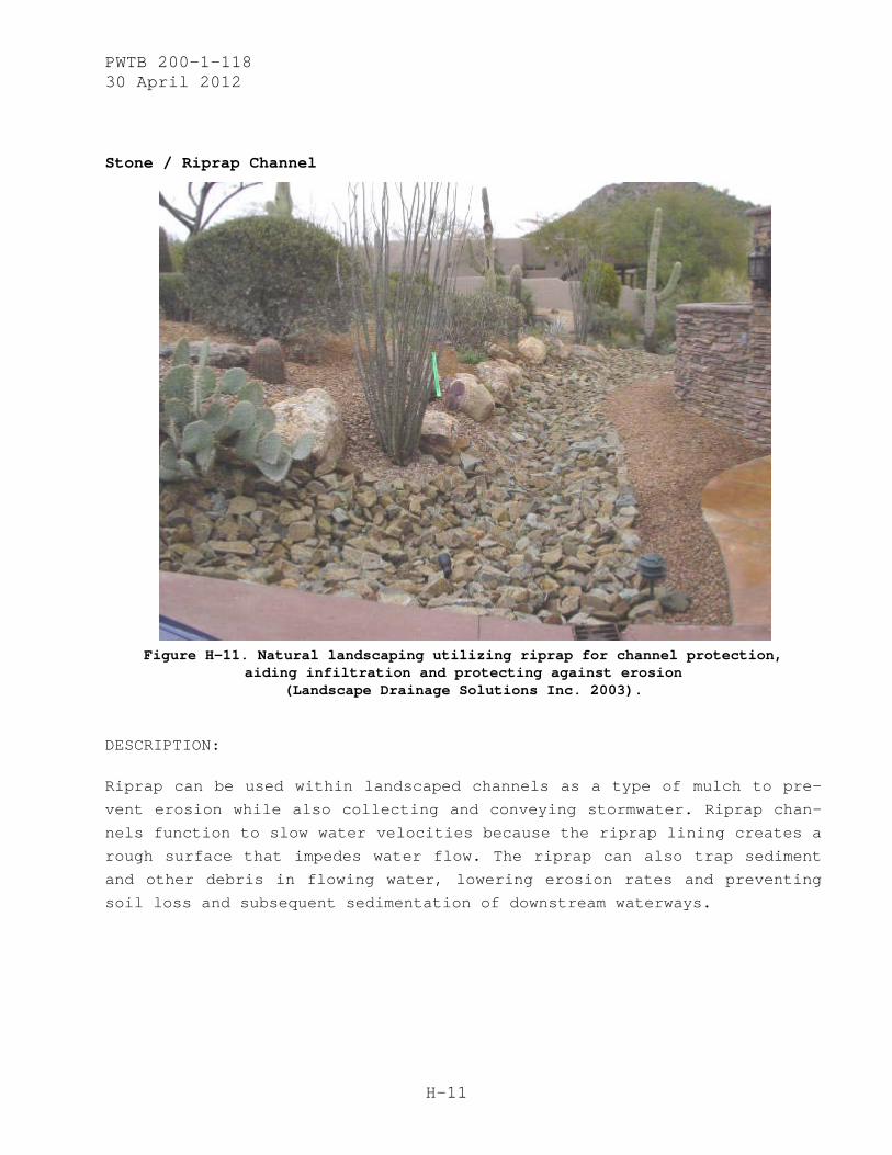
PWTB 200-1-118 30 April 2012
H-11
Stone / Riprap Channel
Figure H-11. Natural landscaping utilizing riprap for channel protection,
aiding infiltration and protecting against erosion (Landscape Drainage Solutions Inc. 2003).
DESCRIPTION:
Riprap can be used within landscaped channels as a type of mulch to pre-
vent erosion while also collecting and conveying stormwater. Riprap chan-
nels function to slow water velocities because the riprap lining creates a
rough surface that impedes water flow. The riprap can also trap sediment
and other debris in flowing water, lowering erosion rates and preventing
soil loss and subsequent sedimentation of downstream waterways.

PWTB 200-1-118 30 April 2012
H-12
Additional Images:
Figure H-12. Diagrams of variations in shape and design of riprap channels for hydraulic flow (UNEP 1994).
Figure H-13. Riprap swale in natural setting (Roberts 2009).

PWTB 200-1-118 30 April 2012
H-13
Surface Landscaping
Figure H-14. Backyard area with surface landscaping (all groundcovers or shrubs
and trees; the ‘lawn’ area is a low groundcover (Harris, 2007)
DESCRIPTION:
Surface landscaping provides enhanced pervious areas for water filtration.
Varied plant choice and topography provides more surface area to detain
water onsite. With more water being detained onsite, in microtopography
and on plant surfaces, not only does less water end up running offsite but
also more water will infiltrate onsite for groundwater recharge and
maintenance of soil moisture levels over longer periods of time.
Additional Image:
Figure H-15. Another area previously grassed, now under conversion into a surface landscape of low-lying groundcovers (Harris, 2007).
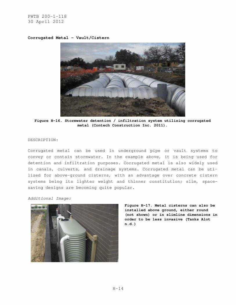
PWTB 200-1-118 30 April 2012
H-14
Corrugated Metal – Vault/Cistern
Figure H-16. Stormwater detention / infiltration system utilizing corrugated
metal (Contech Construction Inc. 2011).
DESCRIPTION:
Corrugated metal can be used in underground pipe or vault systems to
convey or contain stormwater. In the example above, it is being used for
detention and infiltration purposes. Corrugated metal is also widely used
in canals, culverts, and drainage systems. Corrugated metal can be uti-
lized for above-ground cisterns, with an advantage over concrete cistern
systems being its lighter weight and thinner constitution; slim, space-
saving designs are becoming quite popular.
Additional Image:
Figure H-17. Metal cisterns can also be installed above ground, either round (not shown) or in slimline dimensions in order to be less invasive (Tanks Alot n.d.)
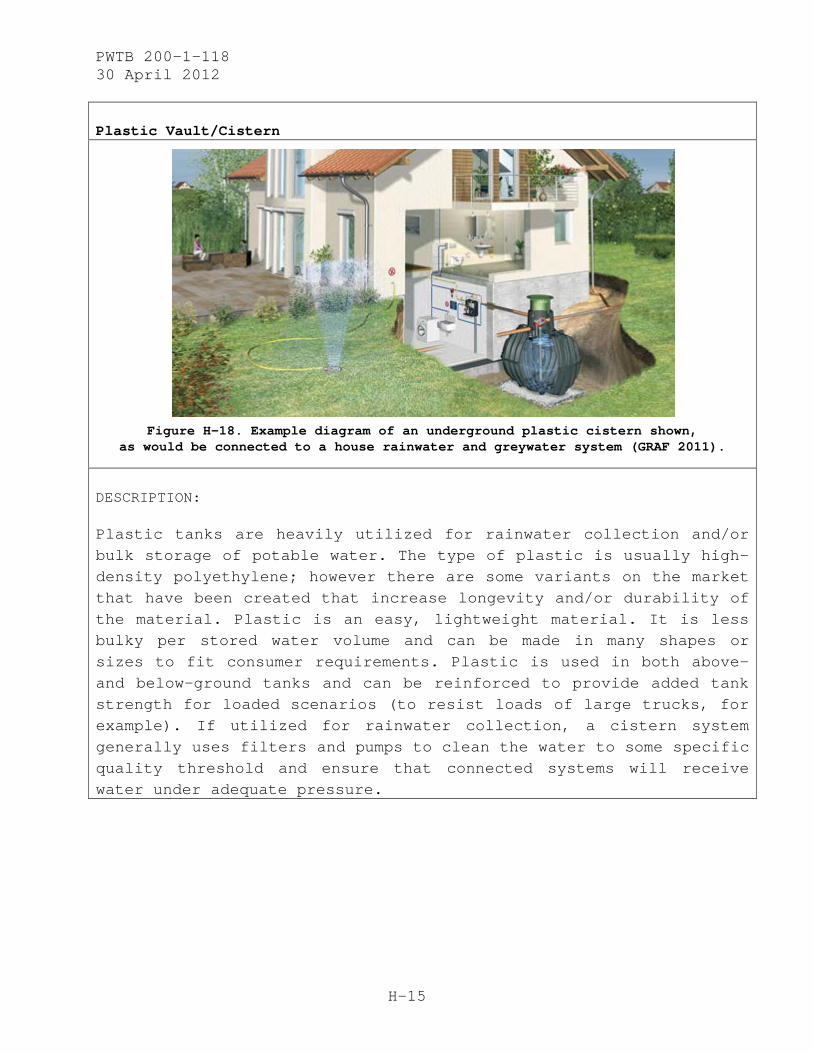
PWTB 200-1-118 30 April 2012
H-15
Plastic Vault/Cistern
Figure H-18. Example diagram of an underground plastic cistern shown,
as would be connected to a house rainwater and greywater system (GRAF 2011).
DESCRIPTION:
Plastic tanks are heavily utilized for rainwater collection and/or bulk storage of potable water. The type of plastic is usually high-density polyethylene; however there are some variants on the market that have been created that increase longevity and/or durability of the material. Plastic is an easy, lightweight material. It is less bulky per stored water volume and can be made in many shapes or sizes to fit consumer requirements. Plastic is used in both above- and below-ground tanks and can be reinforced to provide added tank strength for loaded scenarios (to resist loads of large trucks, for example). If utilized for rainwater collection, a cistern system generally uses filters and pumps to clean the water to some specific quality threshold and ensure that connected systems will receive water under adequate pressure.

PWTB 200-1-118 30 April 2012
H-16
Additional Images:
Figure H-19. Subterranean plastic cistern (The Rain Well n.d.).
Figure H-20. Above-ground rain tank on the side of a residence (RainBarrelSource.com 2011).
Figure H-21. Cisterns in basement of Friends Center (EPA 2009a).

PWTB 200-1-118 30 April 2012
H-17
Precast Concrete – Vault/Cistern
Figure H-22. Precast concrete cistern during installation
(American Concrete Industries n.d).
DESCRIPTION:
Concrete vault or cistern systems are a more traditional material choice for water storage. Generally the concrete is precast because it makes the installation process much simpler. It also allows hard-to-access sites more options for underground concrete cistern sys-tems. Some benefits of using concrete in underground systems include the weight of the concrete. Concrete systems do better in areas where water tables might be higher, as they are not prone to float-ing due to ground pressures. Concrete systems also become more cost-efficient as their overall scale increases, and they work well for larger systems. Disadvantages include required maintenance (re-sealing or relining can be required 10-30 years after installation). Also, although precast systems are easier to install than cast-in-place systems, the bulk and weight of the concrete mean there is less flexibility in siting concrete cisterns.

PWTB 200-1-118 30 April 2012
H-18
Brick Pavers
Figure H-23. Walkway made with brick pavers (Décor Guide 2011).
DESCRIPTION:
Brick pavers can be very decorative; however, they also can be quite
appropriate in certain historical settings. Bricks are very traditional
and have maintained their utility as a functional, strong, durable, and
multi-purpose building material. Bricks can be laid down as pavers in many
different patterns, they come in many different colors (including, but not
limited to, colors ranging from darker red to light red, dark brown to
light brown, and white). For paving purposes, they are laid over gravel
and sand as an impervious surface and then grouted to create a rigid paved
area. For pervious surfaces, they are laid over gravel and/or sand and
then set in sand without rigid joints. This pervious setting allows water
to infiltrate through the bricks and subsequent soil profile, while still
maintaining a load-bearing and durable surface at the ground level.
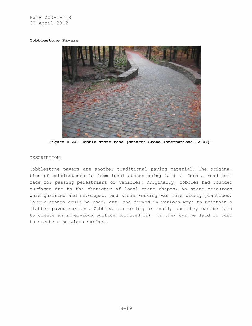
PWTB 200-1-118 30 April 2012
H-19
Cobblestone Pavers
Figure H-24. Cobble stone road (Monarch Stone International 2009).
DESCRIPTION:
Cobblestone pavers are another traditional paving material. The origina-
tion of cobblestones is from local stones being laid to form a road sur-
face for passing pedestrians or vehicles. Originally, cobbles had rounded
surfaces due to the character of local stone shapes. As stone resources
were quarried and developed, and stone working was more widely practiced,
larger stones could be used, cut, and formed in various ways to maintain a
flatter paved surface. Cobbles can be big or small, and they can be laid
to create an impervious surface (grouted-in), or they can be laid in sand
to create a pervious surface.
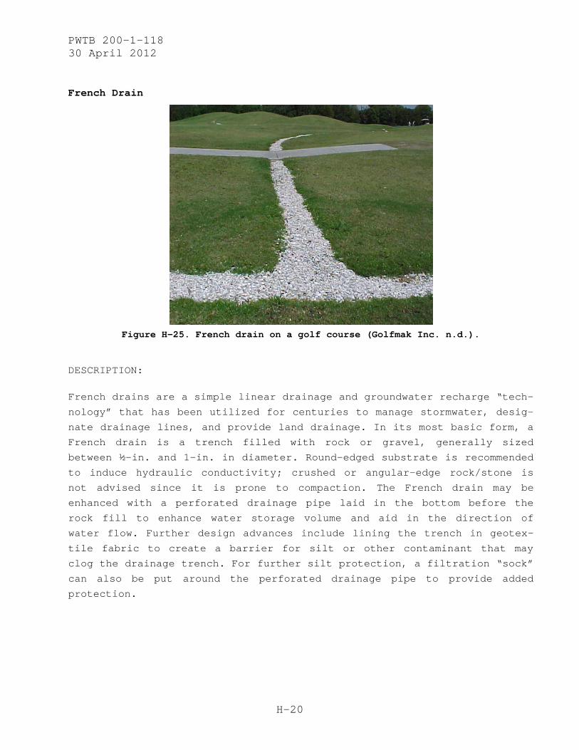
PWTB 200-1-118 30 April 2012
H-20
French Drain
Figure H-25. French drain on a golf course (Golfmak Inc. n.d.).
DESCRIPTION:
French drains are a simple linear drainage and groundwater recharge “tech-
nology” that has been utilized for centuries to manage stormwater, desig-
nate drainage lines, and provide land drainage. In its most basic form, a
French drain is a trench filled with rock or gravel, generally sized
between ½-in. and 1-in. in diameter. Round-edged substrate is recommended
to induce hydraulic conductivity; crushed or angular-edge rock/stone is
not advised since it is prone to compaction. The French drain may be
enhanced with a perforated drainage pipe laid in the bottom before the
rock fill to enhance water storage volume and aid in the direction of
water flow. Further design advances include lining the trench in geotex-
tile fabric to create a barrier for silt or other contaminant that may
clog the drainage trench. For further silt protection, a filtration “sock”
can also be put around the perforated drainage pipe to provide added
protection.

PWTB 200-1-118 30 April 2012
H-21
Additional Image:
Figure H-26. French drain diagram illustrating integration drainage with another LID technology (swale) (Golftmak, Inc. n.d.).
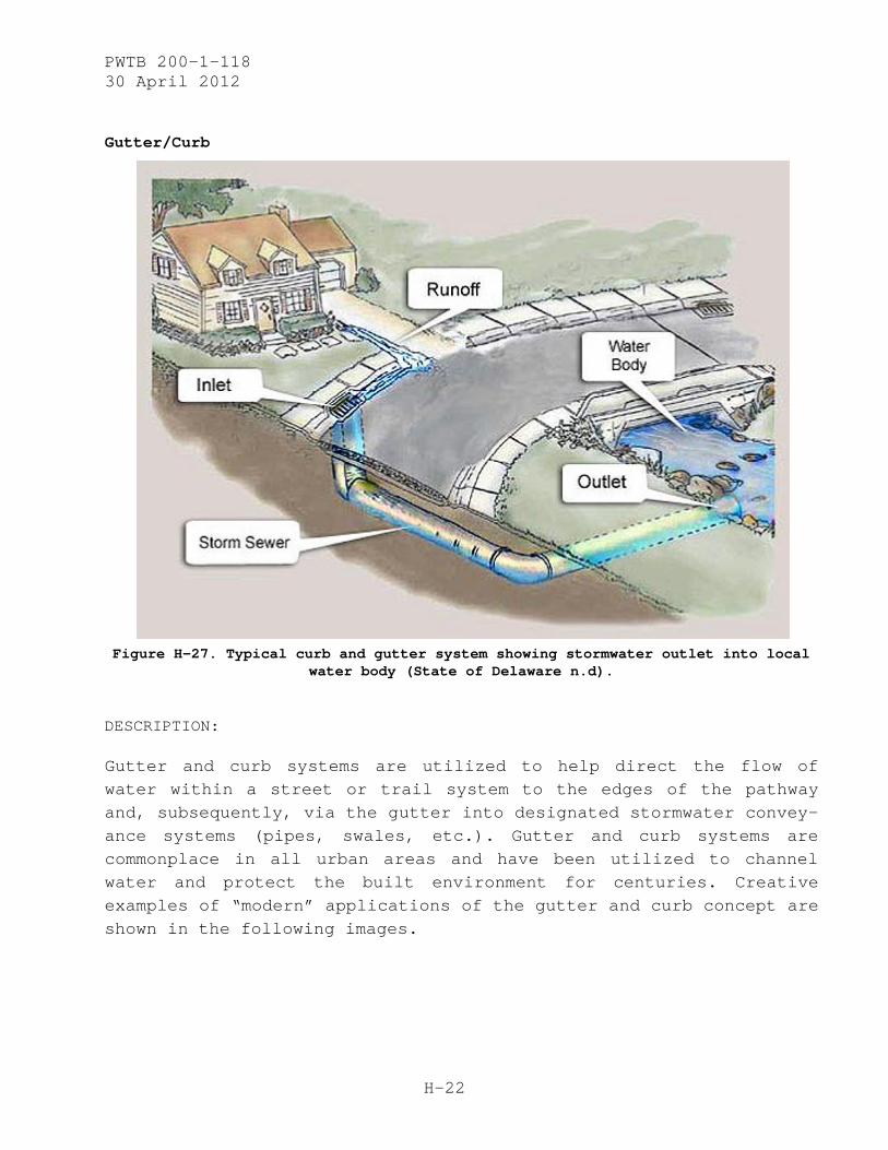
PWTB 200-1-118 30 April 2012
H-22
Gutter/Curb
Figure H-27. Typical curb and gutter system showing stormwater outlet into local
water body (State of Delaware n.d).
DESCRIPTION:
Gutter and curb systems are utilized to help direct the flow of water within a street or trail system to the edges of the pathway and, subsequently, via the gutter into designated stormwater convey-ance systems (pipes, swales, etc.). Gutter and curb systems are commonplace in all urban areas and have been utilized to channel water and protect the built environment for centuries. Creative examples of “modern” applications of the gutter and curb concept are shown in the following images.
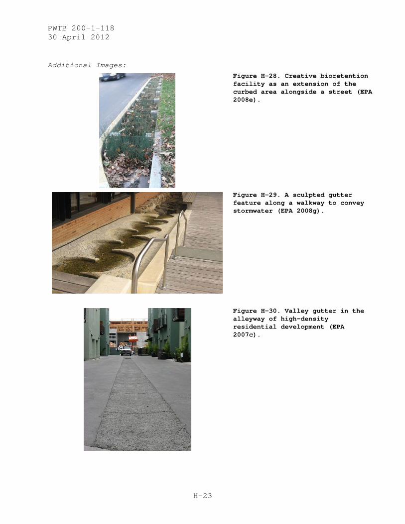
PWTB 200-1-118 30 April 2012
H-23
Additional Images:
Figure H-28. Creative bioretention facility as an extension of the curbed area alongside a street (EPA 2008e).
Figure H-29. A sculpted gutter feature along a walkway to convey stormwater (EPA 2008g).
Figure H-30. Valley gutter in the alleyway of high-density residential development (EPA 2007c).
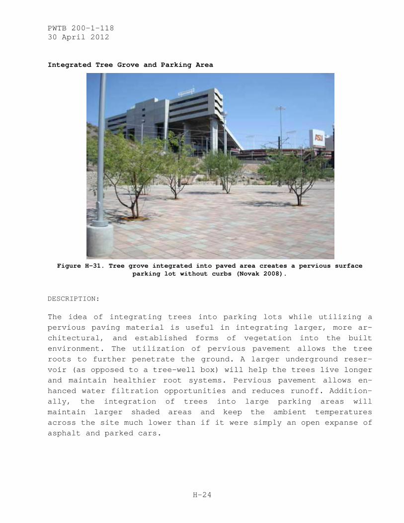
PWTB 200-1-118 30 April 2012
H-24
Integrated Tree Grove and Parking Area
Figure H-31. Tree grove integrated into paved area creates a pervious surface
parking lot without curbs (Novak 2008).
DESCRIPTION:
The idea of integrating trees into parking lots while utilizing a pervious paving material is useful in integrating larger, more ar-chitectural, and established forms of vegetation into the built environment. The utilization of pervious pavement allows the tree roots to further penetrate the ground. A larger underground reser-voir (as opposed to a tree-well box) will help the trees live longer and maintain healthier root systems. Pervious pavement allows en-hanced water filtration opportunities and reduces runoff. Addition-ally, the integration of trees into large parking areas will maintain larger shaded areas and keep the ambient temperatures across the site much lower than if it were simply an open expanse of asphalt and parked cars.
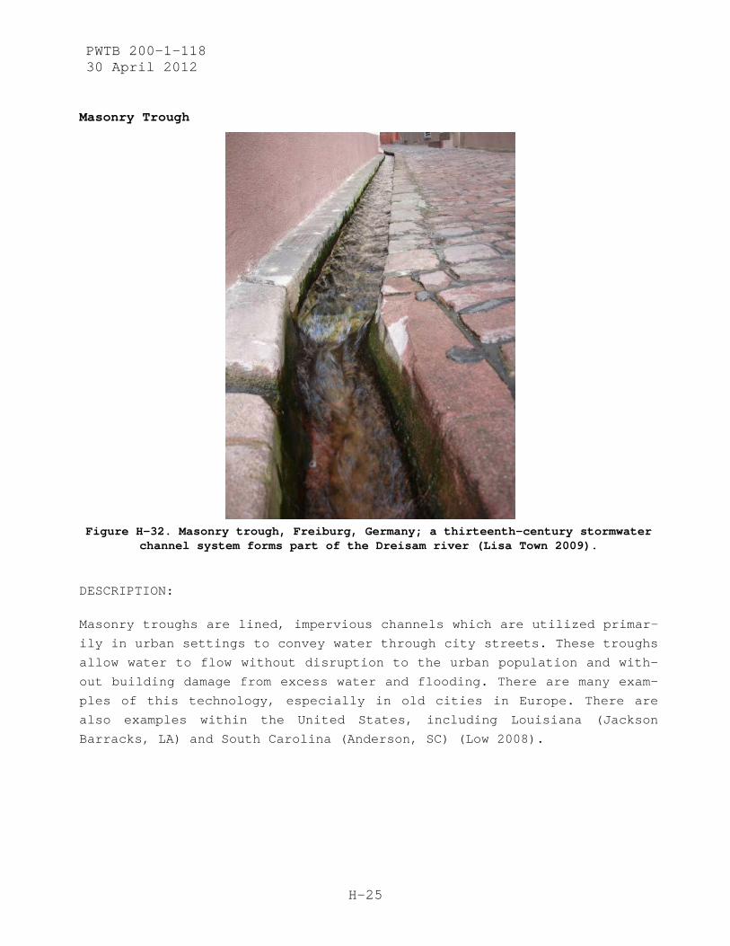
PWTB 200-1-118 30 April 2012
H-25
Masonry Trough
Figure H-32. Masonry trough, Freiburg, Germany; a thirteenth-century stormwater
channel system forms part of the Dreisam river (Lisa Town 2009).
DESCRIPTION:
Masonry troughs are lined, impervious channels which are utilized primar-
ily in urban settings to convey water through city streets. These troughs
allow water to flow without disruption to the urban population and with-
out building damage from excess water and flooding. There are many exam-
ples of this technology, especially in old cities in Europe. There are
also examples within the United States, including Louisiana (Jackson
Barracks, LA) and South Carolina (Anderson, SC) (Low 2008).

PWTB 200-1-118 30 April 2012
H-26
Additional Image:
Figure H-33. Smaller-scale masonry trough utilized in conjunction with urban tree plantings in Grenada, Spain (Low 2008).

PWTB 200-1-118 30 April 2012
H-27
Natural Stone Pavers
Figure H-34. Sandstone pavers used for the walkways (GroundTradesXchange 2008).
DESCRIPTION:
Natural stone pavers are used in the same way as bricks or cobblestones.
They can be any shape, size, or material — the key is that they are gener-
ally made of natural stone and typically stone that is quarried near the
installation site. Specialty projects often source natural stone pavers
that were quarried from distances farther away since design and aesthetic
appearance sometimes is prioritized above cost of materials. Natural stone
pavers can be grouted-in for an impervious surface or laid in sand for a
pervious paving surface. Maintenance requirements are similar to bricks or
cobblestones.

PWTB 200-1-118 30 April 2012
H-28
Turf Block (Grassed Cellular Concrete)
Figure H-35. Turf block used in an entryway drive and parking lot
(Alpine Limited n.d.).
DESCRIPTION:
Turf block or grassed cellular concrete provides both a functional load-bearing “pavement” and a vegetated pervious surface. The turf block fill media can be compromised of native soils or structural filler materials (soils or gravels) as long as higher infiltration rates are supported. Media can then be seeded with grass seed or another type of closely-cropped groundcover to provide vegetated groundcover. With such a system, not only is runoff reduced due to the pervious nature of the vegetated paving system, but also any runoff that is generated (when the underlying soil profile is satu-rated) will have reduced sediment loads and reduced velocity to further reduce off-pavement erosion and sedimentation.
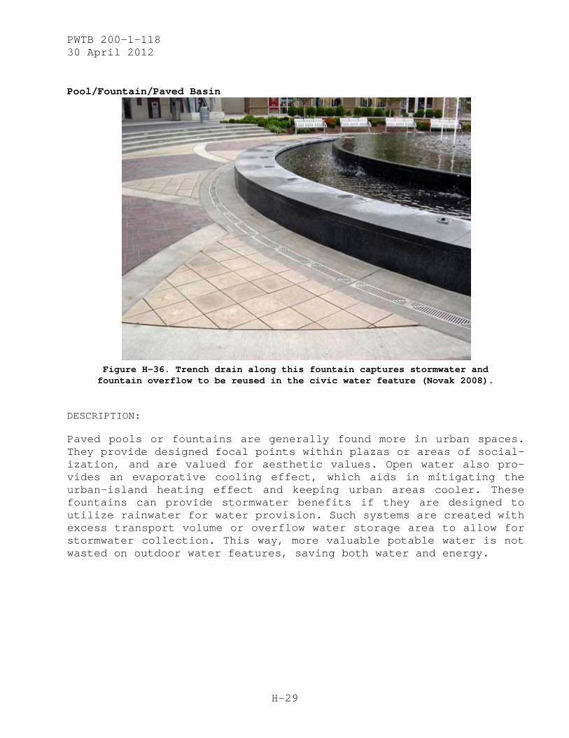
PWTB 200-1-118 30 April 2012
H-29
Pool/Fountain/Paved Basin
Figure H-36. Trench drain along this fountain captures stormwater and fountain overflow to be reused in the civic water feature (Novak 2008).
DESCRIPTION:
Paved pools or fountains are generally found more in urban spaces. They provide designed focal points within plazas or areas of social-ization, and are valued for aesthetic values. Open water also pro-vides an evaporative cooling effect, which aids in mitigating the urban-island heating effect and keeping urban areas cooler. These fountains can provide stormwater benefits if they are designed to utilize rainwater for water provision. Such systems are created with excess transport volume or overflow water storage area to allow for stormwater collection. This way, more valuable potable water is not wasted on outdoor water features, saving both water and energy.
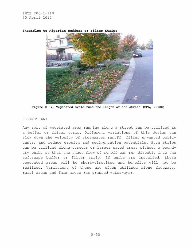
PWTB 200-1-118 30 April 2012
H-30
Sheetflow to Riparian Buffers or Filter Strips
Figure H-37. Vegetated swale runs the length of the street (EPA, 2008k).
DESCRIPTION:
Any sort of vegetated area running along a street can be utilized as a buffer or filter strip. Different variations of this design can slow down the velocity of stormwater runoff, filter unwanted pollu-tants, and reduce erosion and sedimentation potentials. Such strips can be utilized along streets or larger paved areas without a bound-ary curb, so that the sheet flow of runoff can run directly into the softscape buffer or filter strip. If curbs are installed, these vegetated areas will be short-circuited and benefits will not be realized. Variations of these are often utilized along freeways, rural areas and farm areas (as grassed waterways).
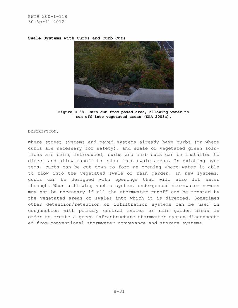
PWTB 200-1-118 30 April 2012
H-31
Swale Systems with Curbs and Curb Cuts
Figure H-38. Curb cut from paved area, allowing water to
run off into vegetated areas (EPA 2008a).
DESCRIPTION:
Where street systems and paved systems already have curbs (or where curbs are necessary for safety), and swale or vegetated green solu-tions are being introduced, curbs and curb cuts can be installed to direct and allow runoff to enter into swale areas. In existing sys-tems, curbs can be cut down to form an opening where water is able to flow into the vegetated swale or rain garden. In new systems, curbs can be designed with openings that will also let water through. When utilizing such a system, underground stormwater sewers may not be necessary if all the stormwater runoff can be treated by the vegetated areas or swales into which it is directed. Sometimes other detention/retention or infiltration systems can be used in conjunction with primary central swales or rain garden areas in order to create a green infrastructure stormwater system disconnect-ed from conventional stormwater conveyance and storage systems.
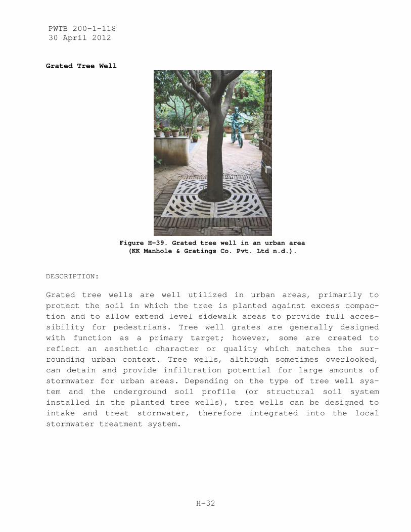
PWTB 200-1-118 30 April 2012
H-32
Grated Tree Well
Figure H-39. Grated tree well in an urban area (KK Manhole & Gratings Co. Pvt. Ltd n.d.).
DESCRIPTION:
Grated tree wells are well utilized in urban areas, primarily to protect the soil in which the tree is planted against excess compac-tion and to allow extend level sidewalk areas to provide full acces-sibility for pedestrians. Tree well grates are generally designed with function as a primary target; however, some are created to reflect an aesthetic character or quality which matches the sur-rounding urban context. Tree wells, although sometimes overlooked, can detain and provide infiltration potential for large amounts of stormwater for urban areas. Depending on the type of tree well sys-tem and the underground soil profile (or structural soil system installed in the planted tree wells), tree wells can be designed to intake and treat stormwater, therefore integrated into the local stormwater treatment system.
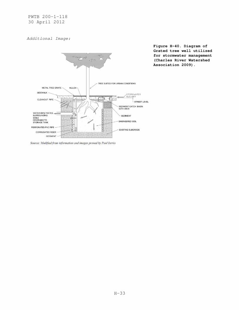
PWTB 200-1-118 30 April 2012
H-33
Additional Image:
Figure H-40. Diagram of Grated tree well utilized for stormwater management (Charles River Watershed Association 2009).

PWTB 200-1-118 30 April 2012
H-34
Asphalt Paving Blocks
Figure H-41. Various examples of asphalt block used as pavers
(Top Asphalt Limited n.d.).
DESCRIPTION:
Asphalt block can be installed in urban areas synonymously to brick pavers, cobblestones, or natural stone pavers. The main difference is that these pavers are actually made of asphalt, which by nature is a semi-flexible pavement material and has specific material prop-erties. Asphalt paving block comes in different colors (primarily red and black), which can be utilized to provide ground surface patterning for either aesthetic design or visual indication of crossing areas, for example. Asphalt block is a cheaper material (as opposed to natural stone paving blocks), so it can provide the ad-vantage of cost efficiency.
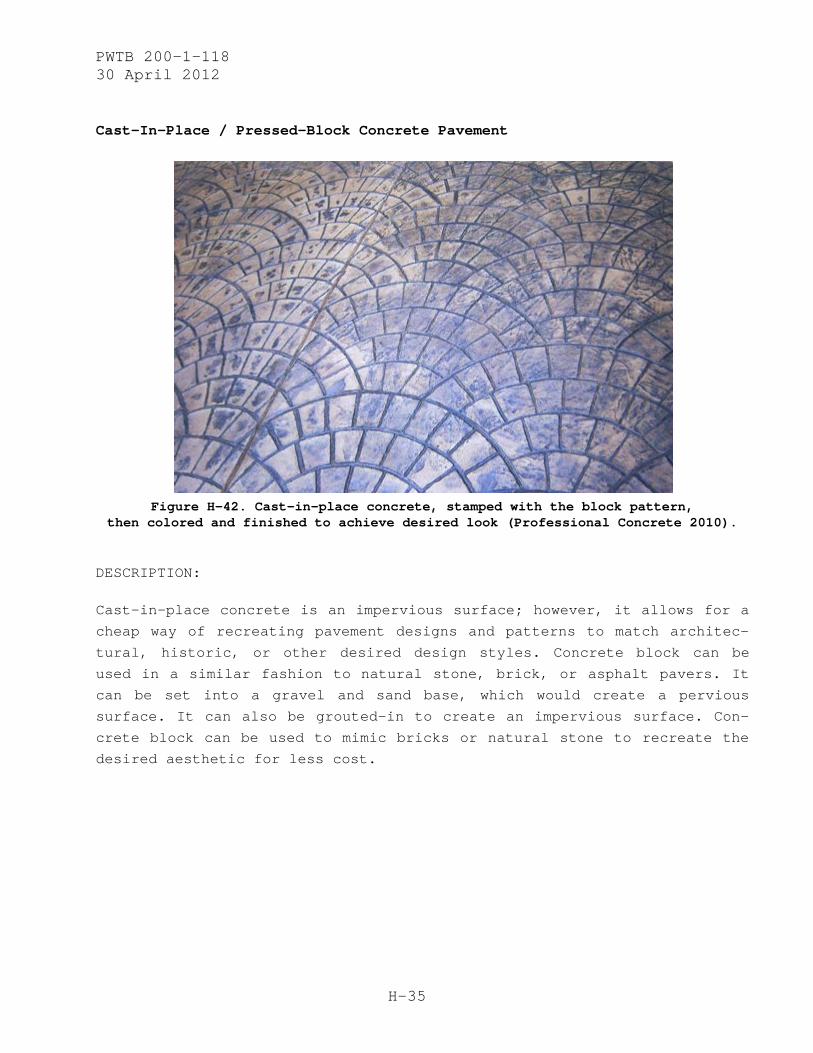
PWTB 200-1-118 30 April 2012
H-35
Cast-In-Place / Pressed-Block Concrete Pavement
Figure H-42. Cast-in-place concrete, stamped with the block pattern,
then colored and finished to achieve desired look (Professional Concrete 2010).
DESCRIPTION:
Cast-in-place concrete is an impervious surface; however, it allows for a
cheap way of recreating pavement designs and patterns to match architec-
tural, historic, or other desired design styles. Concrete block can be
used in a similar fashion to natural stone, brick, or asphalt pavers. It
can be set into a gravel and sand base, which would create a pervious
surface. It can also be grouted-in to create an impervious surface. Con-
crete block can be used to mimic bricks or natural stone to recreate the
desired aesthetic for less cost.
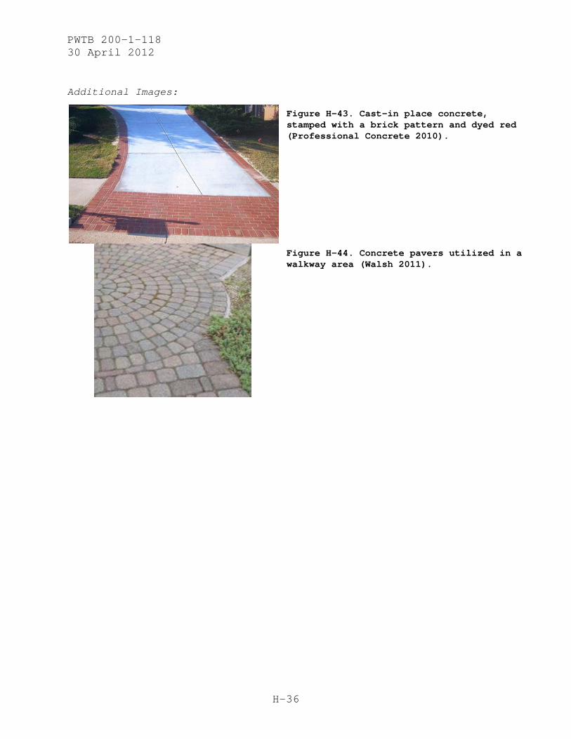
PWTB 200-1-118 30 April 2012
H-36
Additional Images:
Figure H-43. Cast-in place concrete, stamped with a brick pattern and dyed red (Professional Concrete 2010).
Figure H-44. Concrete pavers utilized in a walkway area (Walsh 2011).
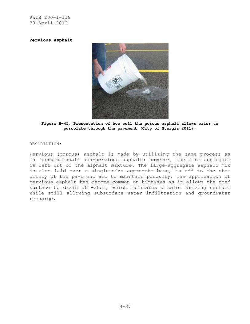
PWTB 200-1-118 30 April 2012
H-37
Pervious Asphalt
Figure H-45. Presentation of how well the porous asphalt allows water to
percolate through the pavement (City of Sturgis 2011).
DESCRIPTION:
Pervious (porous) asphalt is made by utilizing the same process as in “conventional” non-pervious asphalt; however, the fine aggregate is left out of the asphalt mixture. The large-aggregate asphalt mix is also laid over a single-size aggregate base, to add to the sta-bility of the pavement and to maintain porosity. The application of pervious asphalt has become common on highways as it allows the road surface to drain of water, which maintains a safer driving surface while still allowing subsurface water infiltration and groundwater recharge.
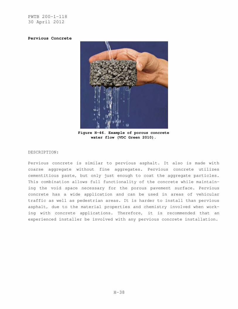
PWTB 200-1-118 30 April 2012
H-38
Pervious Concrete
Figure H-46. Example of porous concrete
water flow (VDC Green 2010).
DESCRIPTION:
Pervious concrete is similar to pervious asphalt. It also is made with
coarse aggregate without fine aggregates. Pervious concrete utilizes
cementitious paste, but only just enough to coat the aggregate particles.
This combination allows full functionality of the concrete while maintain-
ing the void space necessary for the porous pavement surface. Pervious
concrete has a wide application and can be used in areas of vehicular
traffic as well as pedestrian areas. It is harder to install than pervious
asphalt, due to the material properties and chemistry involved when work-
ing with concrete applications. Therefore, it is recommended that an
experienced installer be involved with any pervious concrete installation.
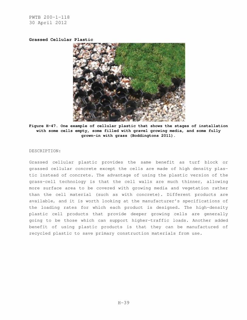
PWTB 200-1-118 30 April 2012
H-39
Grassed Cellular Plastic
Figure H-47. One example of cellular plastic that shows the stages of installation
with some cells empty, some filled with gravel growing media, and some fully grown-in with grass (Boddingtons 2011).
DESCRIPTION:
Grassed cellular plastic provides the same benefit as turf block or
grassed cellular concrete except the cells are made of high density plas-
tic instead of concrete. The advantage of using the plastic version of the
grass-cell technology is that the cell walls are much thinner, allowing
more surface area to be covered with growing media and vegetation rather
than the cell material (such as with concrete). Different products are
available, and it is worth looking at the manufacturer’s specifications of
the loading rates for which each product is designed. The high-density
plastic cell products that provide deeper growing cells are generally
going to be those which can support higher-traffic loads. Another added
benefit of using plastic products is that they can be manufactured of
recycled plastic to save primary construction materials from use.
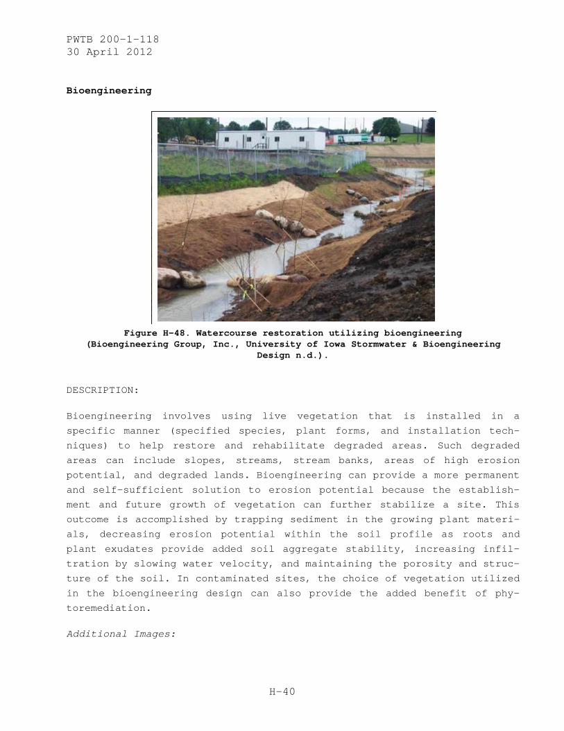
PWTB 200-1-118 30 April 2012
H-40
Bioengineering
Figure H-48. Watercourse restoration utilizing bioengineering
(Bioengineering Group, Inc., University of Iowa Stormwater & Bioengineering Design n.d.).
DESCRIPTION:
Bioengineering involves using live vegetation that is installed in a
specific manner (specified species, plant forms, and installation tech-
niques) to help restore and rehabilitate degraded areas. Such degraded
areas can include slopes, streams, stream banks, areas of high erosion
potential, and degraded lands. Bioengineering can provide a more permanent
and self-sufficient solution to erosion potential because the establish-
ment and future growth of vegetation can further stabilize a site. This
outcome is accomplished by trapping sediment in the growing plant materi-
als, decreasing erosion potential within the soil profile as roots and
plant exudates provide added soil aggregate stability, increasing infil-
tration by slowing water velocity, and maintaining the porosity and struc-
ture of the soil. In contaminated sites, the choice of vegetation utilized
in the bioengineering design can also provide the added benefit of phy-
toremediation.
Additional Images:

PWTB 200-1-118 30 April 2012
H-41
Figure H-49. Example diagram of a swale and watercourse bank stabilized with vegetation utilizing bioengineering techniques (Bioengineering Group, Inc., Upper Connecticut River Habitat Restoration Plan, NH, n.d.).
Figure H-50. Example diagram of a swale showing the use of bioengineering techniques (Bioengineering Group, Inc. n.d.).
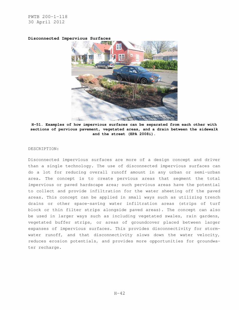
PWTB 200-1-118 30 April 2012
H-42
Disconnected Impervious Surfaces
H-51. Examples of how impervious surfaces can be separated from each other with sections of pervious pavement, vegetated areas, and a drain between the sidewalk
and the street (EPA 2008i).
DESCRIPTION:
Disconnected impervious surfaces are more of a design concept and driver
than a single technology. The use of disconnected impervious surfaces can
do a lot for reducing overall runoff amount in any urban or semi-urban
area. The concept is to create pervious areas that segment the total
impervious or paved hardscape area; such pervious areas have the potential
to collect and provide infiltration for the water sheeting off the paved
areas. This concept can be applied in small ways such as utilizing trench
drains or other space-saving water infiltration areas (strips of turf
block or thin filter strips alongside paved areas). The concept can also
be used in larger ways such as including vegetated swales, rain gardens,
vegetated buffer strips, or areas of groundcover placed between larger
expanses of impervious surfaces. This provides disconnectivity for storm-
water runoff, and that disconnectivity slows down the water velocity,
reduces erosion potentials, and provides more opportunities for groundwa-
ter recharge.
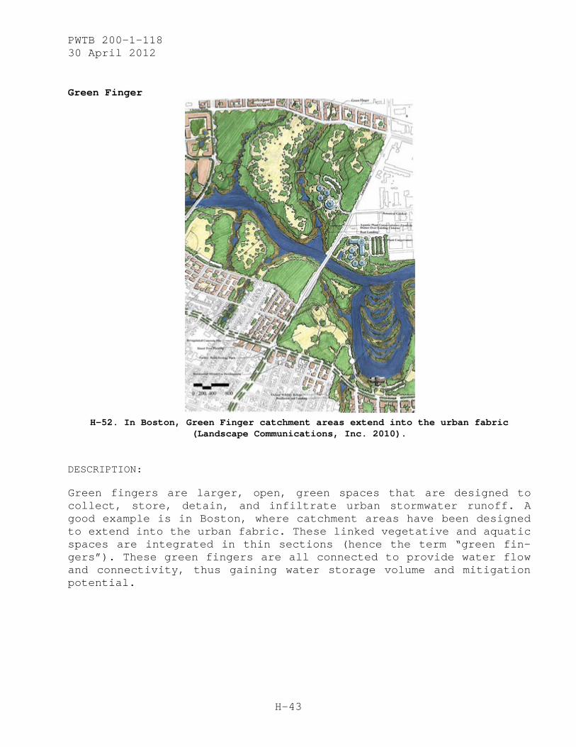
PWTB 200-1-118 30 April 2012
H-43
Green Finger
H-52. In Boston, Green Finger catchment areas extend into the urban fabric
(Landscape Communications, Inc. 2010).
DESCRIPTION:
Green fingers are larger, open, green spaces that are designed to collect, store, detain, and infiltrate urban stormwater runoff. A good example is in Boston, where catchment areas have been designed to extend into the urban fabric. These linked vegetative and aquatic spaces are integrated in thin sections (hence the term “green fin-gers”). These green fingers are all connected to provide water flow and connectivity, thus gaining water storage volume and mitigation potential.

PWTB 200-1-118 30 April 2012
H-44
Geomat
H-53. Newly installed turf reinforcement mat (green) with scour stop mat (white)
(Scourstop 2008).
DESCRIPTION:
Geomats are thick mats that can be made of plastic or organic mate-rials such as jute or coir fibers. The mats are laid and staked into the topsoil (of a newly restored or bare-soil area) in order to prevent soil erosion and allow establishment of vegetative cover. Geomats work by slowing down the velocity of the water running through them and by catching sediment and other organic or non-organic debris within their mesh-like makeup. They can be seeded by overtop broadcast seeding once in place or under-seeded prior to installation. The mesh is also good at keeping the seed in-place, preventing seed loss. In the above picture, a more textured version of a ground mat has been installed at the point of outflow in order to further protect the ground surface below from scour and soil loss. Generally, these geomats are installed permanently. The natu-ral fiber applications will break down over a long period (when vegetation should be permanently established), while the plastic remains to continuously stabilize the soil surface.

PWTB 200-1-118 30 April 2012
H-45
Porous Pavement Underground Recharge Bed
Figure H-54. Diagram of a typical recharge bed
under a porous parking lot (Adams, 2003).
DESCRIPTION:
The use of recharge beds under porous paving is a long-term solution that provides groundwater recharge as well as stormwater detention and retention. Design elements include the installation of porous pavement over a deep bed of aggregate base (much deeper than a typi-cal aggregate base installed under pavement). The recharge bed must be made up of a uniformly graded aggregate with ideal void space of 40 percent. A nonwoven geotextile should be installed between the aggregate and the underlying soil base, which must be a level sur-face to allow the stormwater to be distributed evenly along the bottom of the recharge bed. Also, the soil must remain uncompacted (care must be taken during excavation to prevent subsurface soil compaction). If additional stormwater is being conveyed into the recharge bed (such as from rooftops or other impervious-paved sur-faces), then perforated pipes should be installed into the drain area to evenly distribute the incoming water. Benefits of this sys-tem are many, including -groundwater infiltration and water-quality benefits relative to total suspended solids as well as pollutants. Costs for this type of system, when implemented correctly, are com-parable and sometimes less than conventional impervious paving and stormwater management systems.

PWTB 200-1-118 30 April 2012
H-46
Rain Garden
Figure H-55. A rain garden with an underdrain
(see outlet in gravel just above garden berm left of center; Wilson 2009).
DESCRIPTION:
Rain gardens are small bioretention cells that intake stormwater for detention and infiltration. Rain gardens can be either self-contained or under-drained, depending on site conditions, soil sta-tus, intended water volumes, and available space and budget for the project. The fill media of a rain garden should have high hydraulic conductivity, and the plants that are chosen should be able to with-stand both flooding and drought. A nonwoven geotextile may be used to line the rain garden to aid infiltration and to avoid mixing of soils and filtration media, depending on local conditions and the infiltration media chosen for the rain garden.
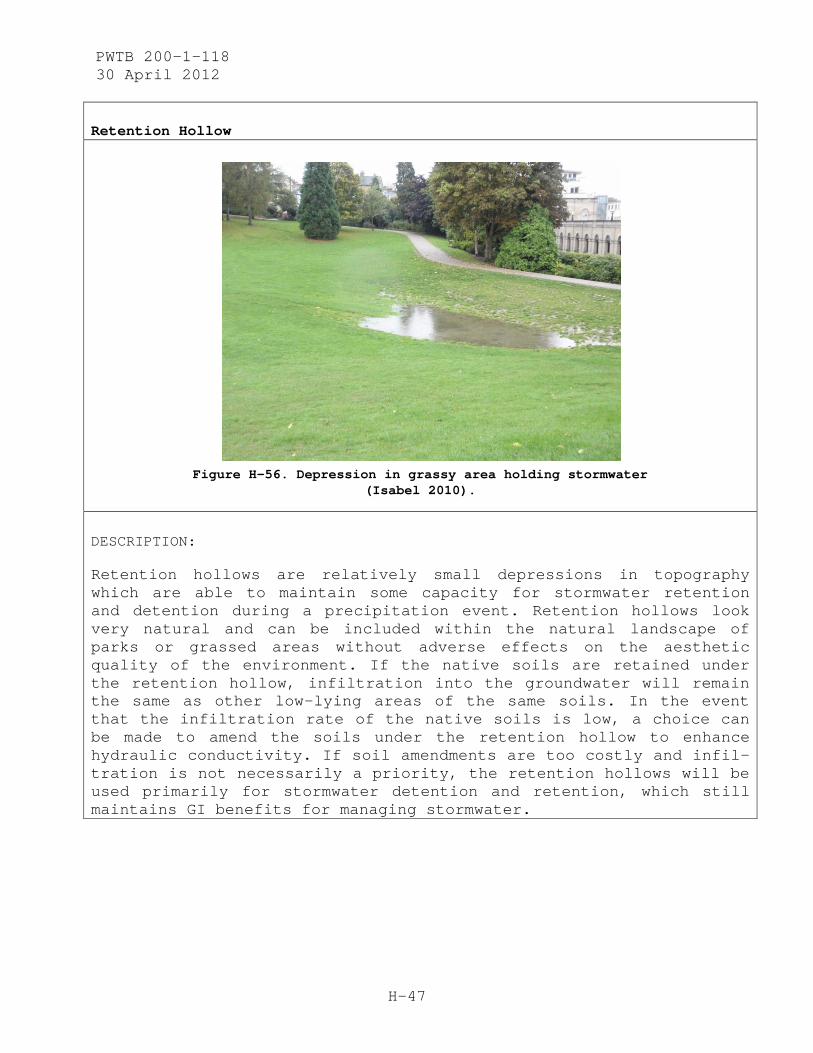
PWTB 200-1-118 30 April 2012
H-47
Retention Hollow
Figure H-56. Depression in grassy area holding stormwater
(Isabel 2010).
DESCRIPTION:
Retention hollows are relatively small depressions in topography which are able to maintain some capacity for stormwater retention and detention during a precipitation event. Retention hollows look very natural and can be included within the natural landscape of parks or grassed areas without adverse effects on the aesthetic quality of the environment. If the native soils are retained under the retention hollow, infiltration into the groundwater will remain the same as other low-lying areas of the same soils. In the event that the infiltration rate of the native soils is low, a choice can be made to amend the soils under the retention hollow to enhance hydraulic conductivity. If soil amendments are too costly and infil-tration is not necessarily a priority, the retention hollows will be used primarily for stormwater detention and retention, which still maintains GI benefits for managing stormwater.
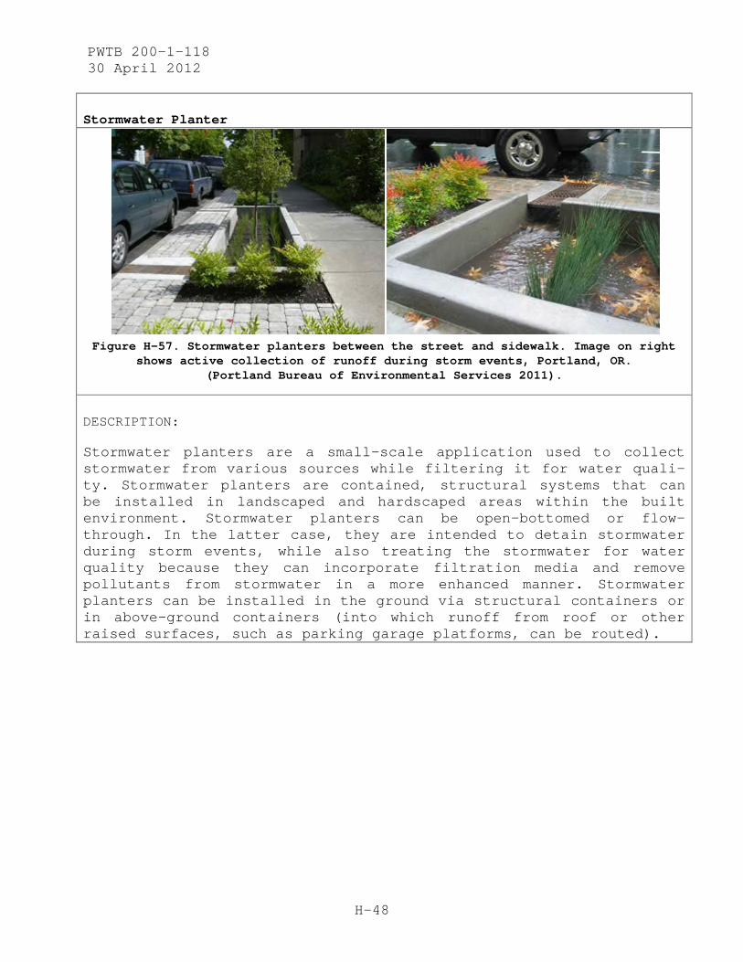
PWTB 200-1-118 30 April 2012
H-48
Stormwater Planter
Figure H-57. Stormwater planters between the street and sidewalk. Image on right
shows active collection of runoff during storm events, Portland, OR. (Portland Bureau of Environmental Services 2011).
DESCRIPTION:
Stormwater planters are a small-scale application used to collect stormwater from various sources while filtering it for water quali-ty. Stormwater planters are contained, structural systems that can be installed in landscaped and hardscaped areas within the built environment. Stormwater planters can be open-bottomed or flow-through. In the latter case, they are intended to detain stormwater during storm events, while also treating the stormwater for water quality because they can incorporate filtration media and remove pollutants from stormwater in a more enhanced manner. Stormwater planters can be installed in the ground via structural containers or in above-ground containers (into which runoff from roof or other raised surfaces, such as parking garage platforms, can be routed).
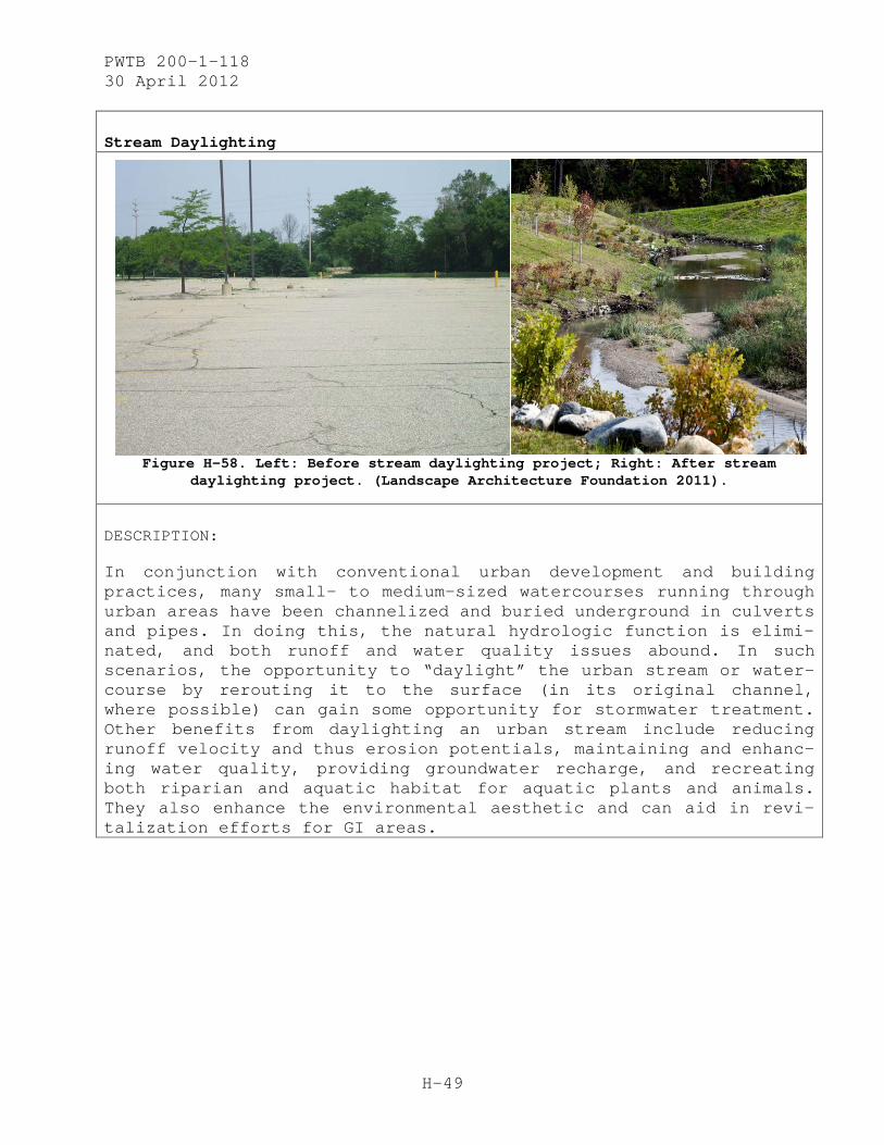
PWTB 200-1-118 30 April 2012
H-49
Stream Daylighting
Figure H-58. Left: Before stream daylighting project; Right: After stream
daylighting project. (Landscape Architecture Foundation 2011).
DESCRIPTION:
In conjunction with conventional urban development and building practices, many small- to medium-sized watercourses running through urban areas have been channelized and buried underground in culverts and pipes. In doing this, the natural hydrologic function is elimi-nated, and both runoff and water quality issues abound. In such scenarios, the opportunity to “daylight” the urban stream or water-course by rerouting it to the surface (in its original channel, where possible) can gain some opportunity for stormwater treatment. Other benefits from daylighting an urban stream include reducing runoff velocity and thus erosion potentials, maintaining and enhanc-ing water quality, providing groundwater recharge, and recreating both riparian and aquatic habitat for aquatic plants and animals. They also enhance the environmental aesthetic and can aid in revi-talization efforts for GI areas.
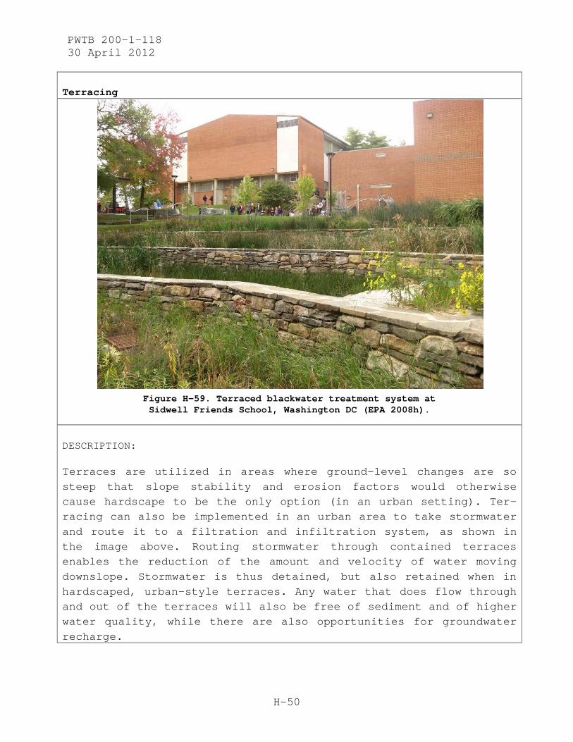
PWTB 200-1-118 30 April 2012
H-50
Terracing
Figure H-59. Terraced blackwater treatment system at Sidwell Friends School, Washington DC (EPA 2008h).
DESCRIPTION:
Terraces are utilized in areas where ground-level changes are so steep that slope stability and erosion factors would otherwise cause hardscape to be the only option (in an urban setting). Ter-racing can also be implemented in an urban area to take stormwater and route it to a filtration and infiltration system, as shown in the image above. Routing stormwater through contained terraces enables the reduction of the amount and velocity of water moving downslope. Stormwater is thus detained, but also retained when in hardscaped, urban-style terraces. Any water that does flow through and out of the terraces will also be free of sediment and of higher water quality, while there are also opportunities for groundwater recharge.
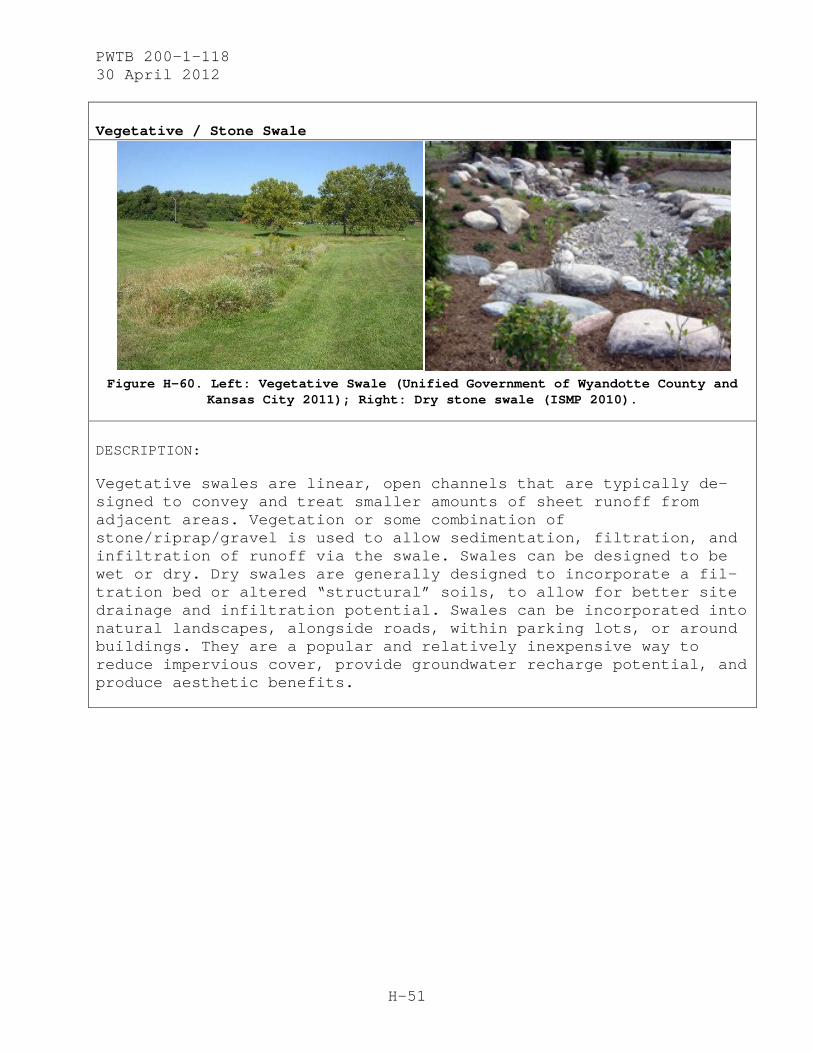
PWTB 200-1-118 30 April 2012
H-51
Vegetative / Stone Swale
Figure H-60. Left: Vegetative Swale (Unified Government of Wyandotte County and
Kansas City 2011); Right: Dry stone swale (ISMP 2010).
DESCRIPTION:
Vegetative swales are linear, open channels that are typically de-signed to convey and treat smaller amounts of sheet runoff from adjacent areas. Vegetation or some combination of stone/riprap/gravel is used to allow sedimentation, filtration, and infiltration of runoff via the swale. Swales can be designed to be wet or dry. Dry swales are generally designed to incorporate a fil-tration bed or altered “structural” soils, to allow for better site drainage and infiltration potential. Swales can be incorporated into natural landscapes, alongside roads, within parking lots, or around buildings. They are a popular and relatively inexpensive way to reduce impervious cover, provide groundwater recharge potential, and produce aesthetic benefits.

PWTB 200-1-118 30 April 2012
H-52
Additional Images:
Figure H-61. Diagram of a vegetative swale with instruction for check dam if slope exceeds 4% gradient (Splash Splash, Technical Standards for Grassed Swales n.d.).
Figure H-62. Stone swale within the landscape (Roberts 2009).
Figure H-63. This swale system in Upton, Northampton, England, implements SUDS to provide flood protection and additional recreation area (Sustainable cities™ n.d.).
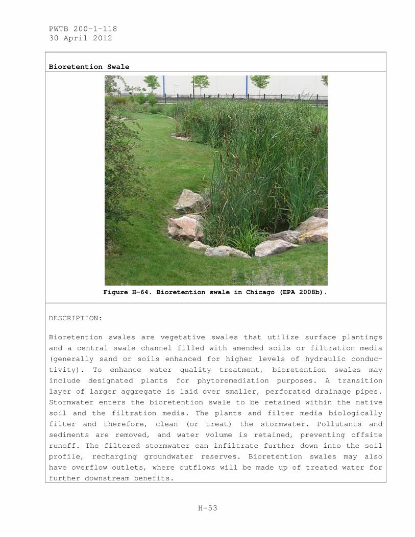
PWTB 200-1-118 30 April 2012
H-53
Bioretention Swale
Figure H-64. Bioretention swale in Chicago (EPA 2008b).
DESCRIPTION:
Bioretention swales are vegetative swales that utilize surface plantings
and a central swale channel filled with amended soils or filtration media
(generally sand or soils enhanced for higher levels of hydraulic conduc-
tivity). To enhance water quality treatment, bioretention swales may
include designated plants for phytoremediation purposes. A transition
layer of larger aggregate is laid over smaller, perforated drainage pipes.
Stormwater enters the bioretention swale to be retained within the native
soil and the filtration media. The plants and filter media biologically
filter and therefore, clean (or treat) the stormwater. Pollutants and
sediments are removed, and water volume is retained, preventing offsite
runoff. The filtered stormwater can infiltrate further down into the soil
profile, recharging groundwater reserves. Bioretention swales may also
have overflow outlets, where outflows will be made up of treated water for
further downstream benefits.
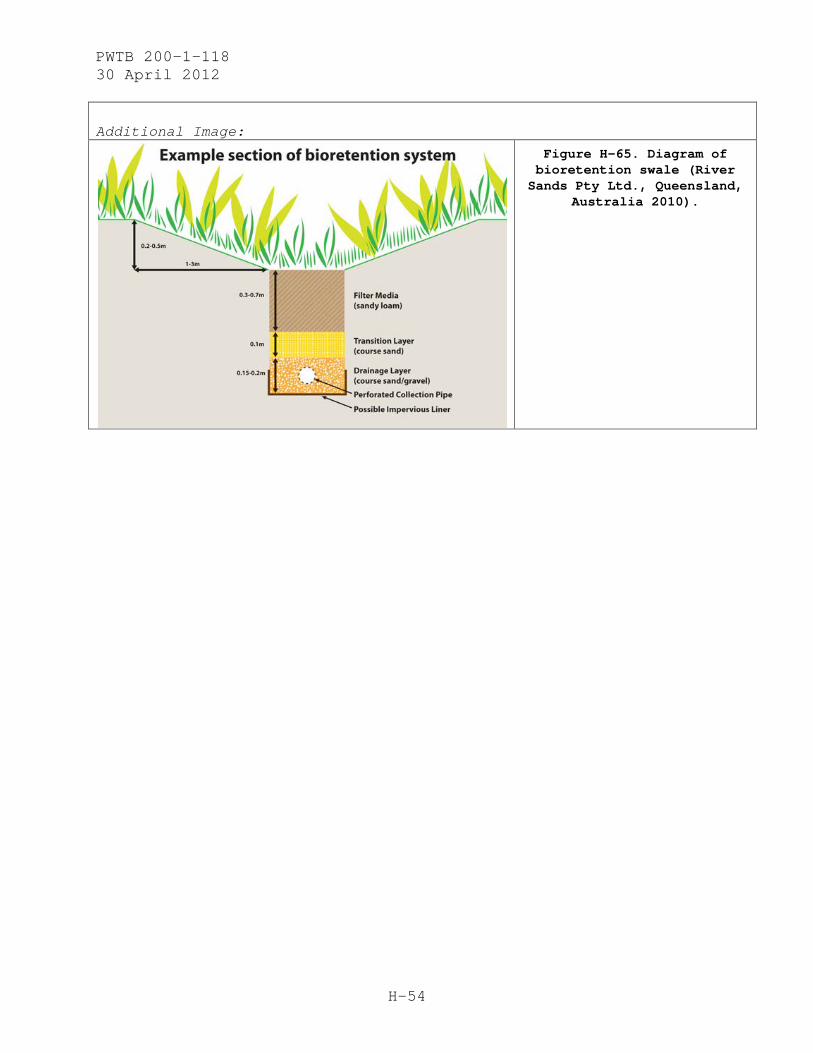
PWTB 200-1-118 30 April 2012
H-54
Additional Image:
Figure H-65. Diagram of bioretention swale (River Sands Pty Ltd., Queensland,
Australia 2010).
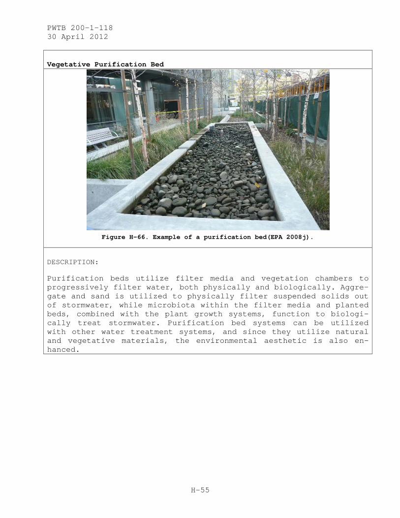
PWTB 200-1-118 30 April 2012
H-55
Vegetative Purification Bed
Figure H-66. Example of a purification bed(EPA 2008j).
DESCRIPTION:
Purification beds utilize filter media and vegetation chambers to progressively filter water, both physically and biologically. Aggre-gate and sand is utilized to physically filter suspended solids out of stormwater, while microbiota within the filter media and planted beds, combined with the plant growth systems, function to biologi-cally treat stormwater. Purification bed systems can be utilized with other water treatment systems, and since they utilize natural and vegetative materials, the environmental aesthetic is also en-hanced.
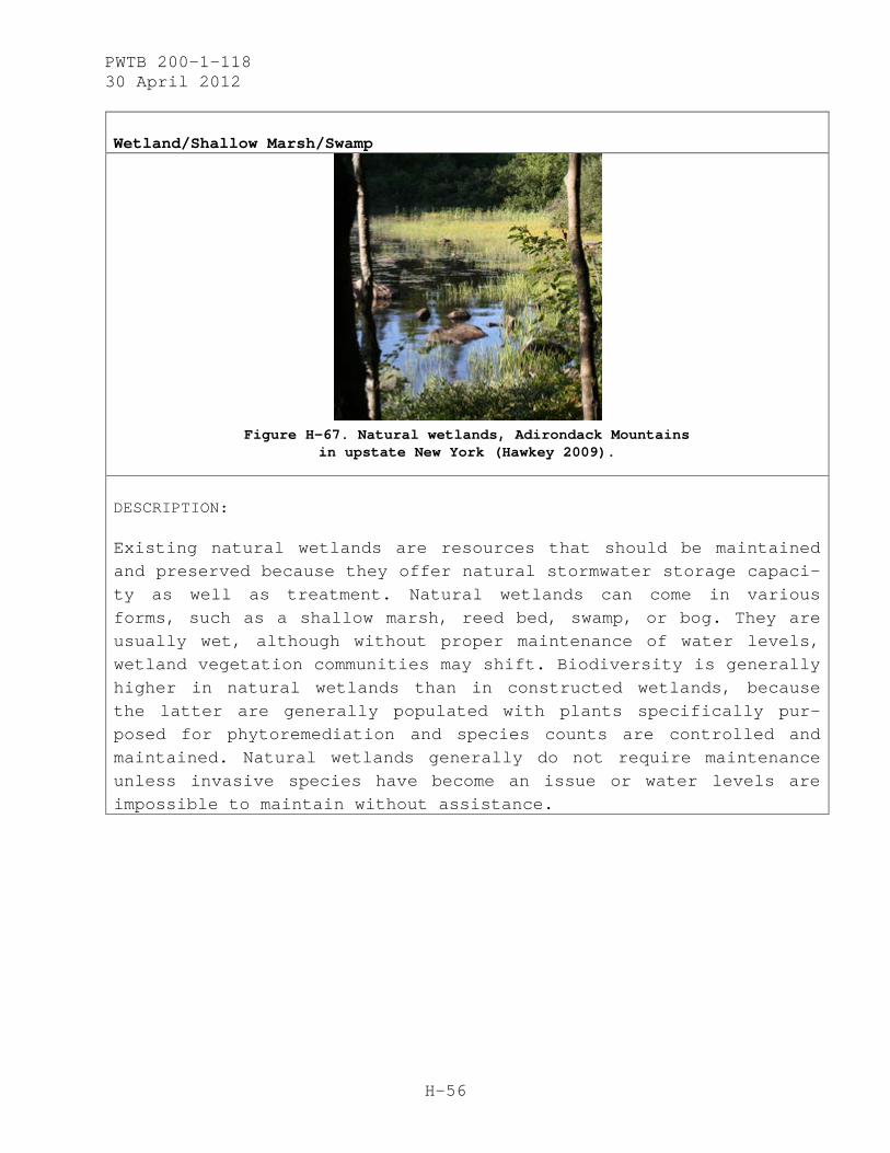
PWTB 200-1-118 30 April 2012
H-56
Wetland/Shallow Marsh/Swamp
Figure H-67. Natural wetlands, Adirondack Mountains
in upstate New York (Hawkey 2009).
DESCRIPTION:
Existing natural wetlands are resources that should be maintained and preserved because they offer natural stormwater storage capaci-ty as well as treatment. Natural wetlands can come in various forms, such as a shallow marsh, reed bed, swamp, or bog. They are usually wet, although without proper maintenance of water levels, wetland vegetation communities may shift. Biodiversity is generally higher in natural wetlands than in constructed wetlands, because the latter are generally populated with plants specifically pur-posed for phytoremediation and species counts are controlled and maintained. Natural wetlands generally do not require maintenance unless invasive species have become an issue or water levels are impossible to maintain without assistance.
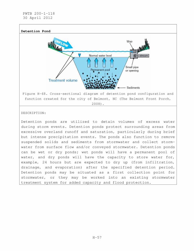
PWTB 200-1-118 30 April 2012
H-57
Detention Pond
Figure H-68. Cross-sectional diagram of detention pond configuration and
function created for the city of Belmont, NC (The Belmont Front Porch,
2008).
DESCRIPTION:
Detention ponds are utilized to detain volumes of excess water during storm events. Detention ponds protect surrounding areas from excessive overland runoff and saturation, particularly during brief but intense precipitation events. The ponds also function to remove suspended solids and sediments from stormwater and collect storm-water from surface flow and/or conveyed stormwater. Detention ponds can be wet or dry ponds; wet ponds will have a permanent pool of water, and dry ponds will have the capacity to store water for, example, 24 hours but are expected to dry up (from infiltration, drainage, and evaporation) after the specified detention period. Detention ponds may be situated as a first collection point for stormwater, or they may be worked into an existing stormwater treatment system for added capacity and flood protection.

PWTB 200-1-118 30 April 2012
H-58
Roof Garden / Green Roof
Figure H-69. Green roof in Portland, OR, with street planters below (EPA 2008c).
DESCRIPTION:
Green roofs are a type of GI technology whereby plants are grown in engineered soils or growing media on the roofs of buildings. The addition of a green roof to a building involves the installation of a waterproofing and drainage system on the roof, along with growing media, plants, and (where necessary) some supplemental irrigation. (Note: not all green roofs need extra water, and some that do can utilize rainwater harvesting or water from air-conditioning conden-sate.) One of the largest incentives for installing a green roof is the absorption of rainwater during storm events to eliminate runoff from the building’s roof. Green roofs also provide insulation, help-ing the building maintain internal temperatures relative to fluctu-ating weather and seasonality. If done on a city building, green roofs help combat the urban heat island effect. Green roofs are an ancient technology that has been utilized in traditional manners in many places of the world; contemporary installations utilize new green roof technologies, since they must be integrated into modern-day structures.

PWTB 200-1-118 30 April 2012
H-59
Canal
Figure H-70. Canals and homes off Roy Creek in Assawoman Bay, MD (Woerner 2006).
DESCRIPTION:
Canals have been utilized historically to channelize previously natural watercourses, provide commercial and private transportation, or to keep adjacent residential areas free of water. With regard to stormwater control and management, it should be recognized that canals also offer water storage capacity and land drainage poten-tial, especially in areas of high water tables or frequent flooding. In residential areas such as the one shown in the image above, the aesthetic and recreational amenity (for boating, fishing, etc.) can also be realized. Canals are generally connected to other local or regional waterways via locks, sluice gate systems, or naturally formed connections so that water levels are maintained over larger areas of land.

PWTB 200-1-118 30 April 2012
H-60
Compacted Earth
Figure H-71. Stabilized road surface made from compacted earth
(Total Earthworks and Environmental Services n.d.).
DESCRIPTION:
Instead of installing a hard pavement surface, compacted earth can be used in rural areas or in support/service areas within a more urban environment. To minimize maintenance costs, compacted earth roads work best in areas where storm intensity and frequency is less (less washout and erosion). Benefits from installing compacted earth roads are the pervious, more natural, surface and the ability to withstand light-to-medium traffic. Yearly or seasonal maintenance should be done to ensure correct soil profile mixture for road sta-bility and to maintain a level surface that protects against extreme wear and tear.
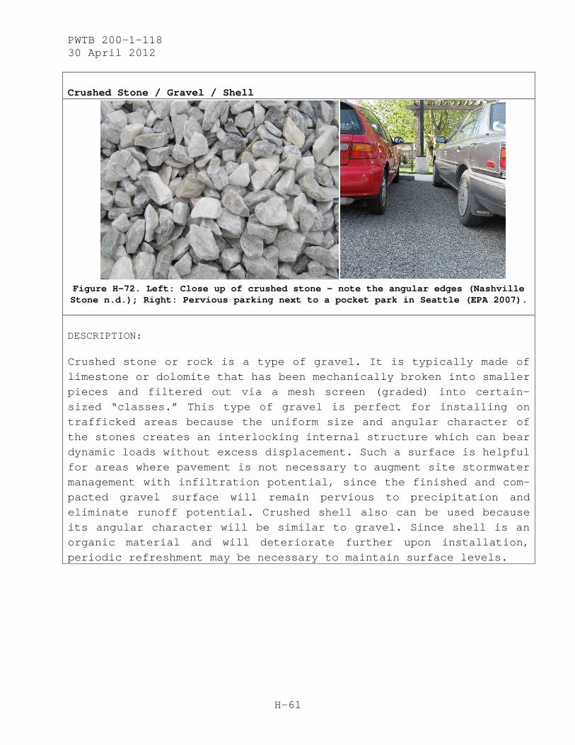
PWTB 200-1-118 30 April 2012
H-61
Crushed Stone / Gravel / Shell
Figure H-72. Left: Close up of crushed stone – note the angular edges (Nashville Stone n.d.); Right: Pervious parking next to a pocket park in Seattle (EPA 2007).
DESCRIPTION:
Crushed stone or rock is a type of gravel. It is typically made of limestone or dolomite that has been mechanically broken into smaller pieces and filtered out via a mesh screen (graded) into certain-sized “classes.” This type of gravel is perfect for installing on trafficked areas because the uniform size and angular character of the stones creates an interlocking internal structure which can bear dynamic loads without excess displacement. Such a surface is helpful for areas where pavement is not necessary to augment site stormwater management with infiltration potential, since the finished and com-pacted gravel surface will remain pervious to precipitation and eliminate runoff potential. Crushed shell also can be used because its angular character will be similar to gravel. Since shell is an organic material and will deteriorate further upon installation, periodic refreshment may be necessary to maintain surface levels.

PWTB 200-1-118 30 April 2012
H-62
Vegetation Islands / Planting Strip Trenches
Figure H-73. Vegetative swale utilized in a parking lot
in Portland, OR (EPA 2007b).
DESCRIPTION:
The use of vegetative swales in parking lots is multifunctional: they help soften an otherwise bland landscape, reduce traffic noise, and create a diverse and stimulating visual environment. If trees are involved, the vegetation can also contribute to shade coverage; in certain areas, shade coverage also can help meet development compliance requirements. Installing vegetation in non-trafficked areas within parking lots also provides a large benefit to the on-site stormwater management. Not only does it retain pervious areas to receive precipitation, but also these vegetated areas should receive some of the runoff from the parking lot. In many cases (de-pending on the native soils and local hydrology), the parking lot swales can ensure that all runoff is dealt with onsite for most precipitation events, thereby reducing the impact to adjacent, con-ventional stormwater systems. Curb cuts (or concrete channeling), gutter systems, or drainage trenches can be implemented to convey runoff from the paved area to the vegetated swales.

PWTB 200-1-118 30 April 2012
H-63
Additional Image:
Figure H-74. Planting strip within parking area in Portland, OR, serving as a planting strip trench (EPA 2008d).
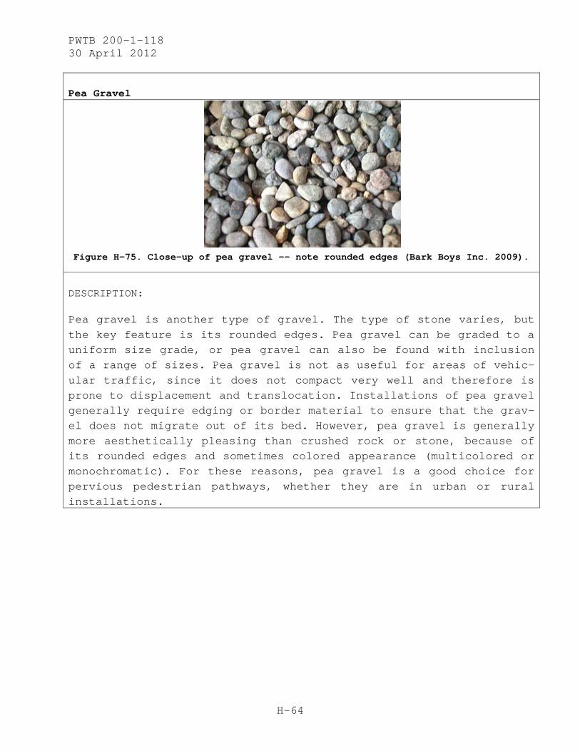
PWTB 200-1-118 30 April 2012
H-64
Pea Gravel
Figure H-75. Close-up of pea gravel –— note rounded edges (Bark Boys Inc. 2009).
DESCRIPTION:
Pea gravel is another type of gravel. The type of stone varies, but the key feature is its rounded edges. Pea gravel can be graded to a uniform size grade, or pea gravel can also be found with inclusion of a range of sizes. Pea gravel is not as useful for areas of vehic-ular traffic, since it does not compact very well and therefore is prone to displacement and translocation. Installations of pea gravel generally require edging or border material to ensure that the grav-el does not migrate out of its bed. However, pea gravel is generally more aesthetically pleasing than crushed rock or stone, because of its rounded edges and sometimes colored appearance (multicolored or monochromatic). For these reasons, pea gravel is a good choice for pervious pedestrian pathways, whether they are in urban or rural installations.

PWTB 200-1-118 30 April 2012
H-65
Wood Paving Blocks
Figure H-76. Wood paving blocks (Vancouver Modern Residential Blog 2010).
DESCRIPTION:
Wood paving blocks are a traditional material utilized in areas where wood resources were more available than stone. Although they do not last as long as stone, in a historic district where wood pavers were the original material, they can be installed to maintain the historic character and support the historic preservation of the area. Historically, wood pavers were installed over stabilized lay-ers of aggregate. Today, more permanent installations of wood paving blocks feature them installed over, or grouted into, concrete. Wood pavers will never be a permanent solution and will always require maintenance because they are an organic material. If installed in an area where precipitation is common, the wood should be a hardwood with high oil content, to resist degradation. Softer or local varie-ties of wood that otherwise would not be ideal for the application can be treated to help them resist water damage and deterioration. If installed in a dry climate over sand, wood pavers can be utilized as a pervious surface pavement for foot traffic or light vehicular traffic, allowing local infiltration during heavy storm events.
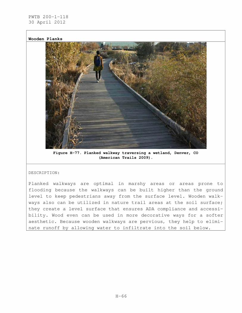
PWTB 200-1-118 30 April 2012
H-66
Wooden Planks
Figure H-77. Planked walkway traversing a wetland, Denver, CO
(American Trails 2009).
DESCRIPTION:
Planked walkways are optimal in marshy areas or areas prone to flooding because the walkways can be built higher than the ground level to keep pedestrians away from the surface level. Wooden walk-ways also can be utilized in nature trail areas at the soil surface; they create a level surface that ensures ADA compliance and accessi-bility. Wood even can be used in more decorative ways for a softer aesthetic. Because wooden walkways are pervious, they help to elimi-nate runoff by allowing water to infiltrate into the soil below.
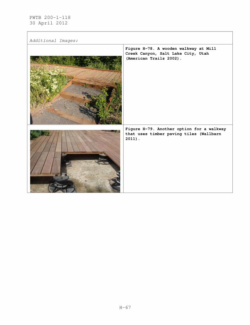
PWTB 200-1-118 30 April 2012
H-67
Additional Images:
Figure H-78. A wooden walkway at Mill Creek Canyon, Salt Lake City, Utah (American Trails 2002).
Figure H-79. Another option for a walkway that uses timber paving tiles (Wallbarn 2011).

PWTB 200-1-118 30 April 2012
H-68
Constructed Wetland
Figure H-80. Constructed wetland at Fort Hood, TX (CERL 2011).
DESCRIPTION:
Constructed wetlands are artificial (manmade) water treatment sys-tems. The water they are designed to treat may come from municipal, industrial, or agricultural wastewater, urban runoff, or even acid mine drainage. Constructed wetlands are specially structured shallow ponds or channels that make up treatment cells, created within a built and partially controlled and designed layout, and planted with aquatic plants. Constructed wetlands rely on natural microbial, biological, physical, and chemical processes to treat wastewater. Depending on the type of water they are designed to treat and the environmental considerations, constructed wetlands may function as the central treatment component of a water treatment system that requires minimal pre- or post-treatment (EPA 2000b).
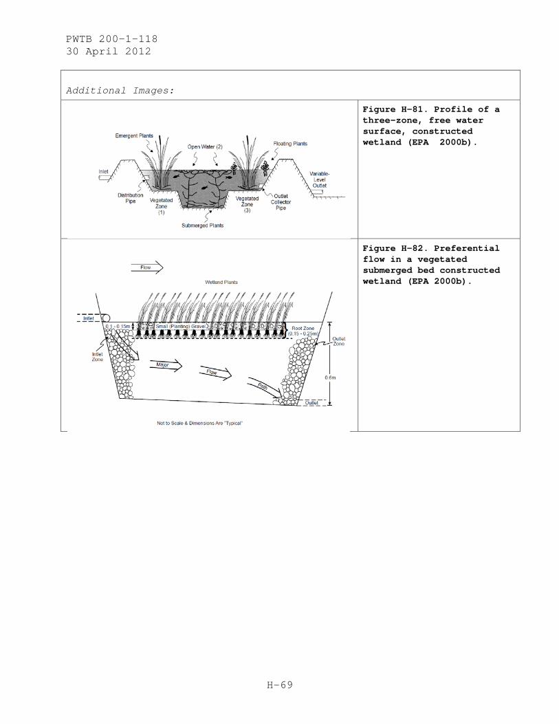
PWTB 200-1-118 30 April 2012
H-69
Additional Images:
Figure H-81. Profile of a three-zone, free water surface, constructed wetland (EPA 2000b).
Figure H-82. Preferential flow in a vegetated submerged bed constructed wetland (EPA 2000b).
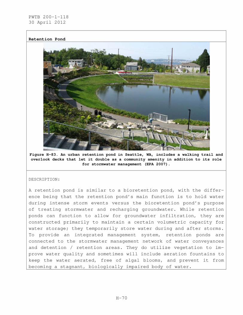
PWTB 200-1-118 30 April 2012
H-70
Retention Pond
Figure H-83. An urban retention pond in Seattle, WA, includes a walking trail and overlook decks that let it double as a community amenity in addition to its role
for stormwater management (EPA 2007).
DESCRIPTION:
A retention pond is similar to a bioretention pond, with the differ-ence being that the retention pond’s main function is to hold water during intense storm events versus the bioretention pond’s purpose of treating stormwater and recharging groundwater. While retention ponds can function to allow for groundwater infiltration, they are constructed primarily to maintain a certain volumetric capacity for water storage; they temporarily store water during and after storms. To provide an integrated management system, retention ponds are connected to the stormwater management network of water conveyances and detention / retention areas. They do utilize vegetation to im-prove water quality and sometimes will include aeration fountains to keep the water aerated, free of algal blooms, and prevent it from becoming a stagnant, biologically impaired body of water.

PWTB 200-1-118 30 April 2012
H-71
Additional Image:
Figure H-84. Large retention basin, with vertical stone walls and protective fence to allow steeper pond edges and therefore, maximize retention volume capacity (EPA 2007).

PWTB 200-1-118 30 April 2012
H-72
Flowing Waterscapes
Seattle’s Thornton Creek Water Quality Channel
(Seattle Public Utilities 2009)
DESCRIPTION:
Flowing waterscapes are watercourses that have been integrated into the built environment, and are designed to accommodate a flowing linear watercourse, with both pools of water linked together via natural skinner stream-like channels. The pool system collects, detains, and retains water; it also treats, filters, and provides potential groundwater recharge. Built into the system’s pool and linkages areas are added capacities for flooding, which are de-signed to look natural and accommodate multiple water levels for designated periods of time.

PWTB 200-1-118 30 April 2012
H-73
Additional Image:
Figure H-85. Terraview Park and Willowfield Gardens Park in Toronto, Ontario, utilize the flow of Massey Creek within created and linked pools of water to collect and filter area stormwater (Anderson 2010).

PWTB 200-1-118 30 April 2012
H-74
Purification Biotope
Figure H-86. Diagram of a planted purification biotope system,
Potsdamer Platz (Rojas n.d.).
DESCRIPTION:
Purification biotopes are similar to vegetative purification beds, except they are a closed system with water flow generated by water pumps. Conceptually, it is similar to an aquarium filtration system, except at a much larger scale and with planted dry areas integrated into the system for nutrient and pollutant uptake, biological fil-tration, and transpiration potential. Purification biotopes are intended to treat stormwater and are sealed off from the groundwa-ter. However the cleaned water can be conveyed offsite and, provided it has been cleaned adequately, could theoretically be delivered to an area where groundwater recharge is possible.

PWTB 200-1-118 30 April 2012
H-75
Slope Avenue
Figure H-87. An example of a slope avenue at Baldin Park, FL
(Low 2008).
DESCRIPTION:
A slope avenue is similar to a terrace, but utilized for water. Varied permutations of a terraced waterway can be found in parks and recreational areas. In a slope avenue, terraced pools of water are connected together by weir structures (slotted rock weirs, water ladders, and crump weirs) that function to slow water velocity, maintain water levels, and aerate flowing water. Such an installa-tion can also be created with bypassing sluice gates, to keep water flowing even during periods of low precipitation, while also main-taining high water levels and storage capacities during wet seasons. By utilizing such water control features and anticipating incoming volumes of stormwater, a slope avenue can be beneficial to helping reduce flood risk while maintaining a natural watercourse and a recreational aesthetic.
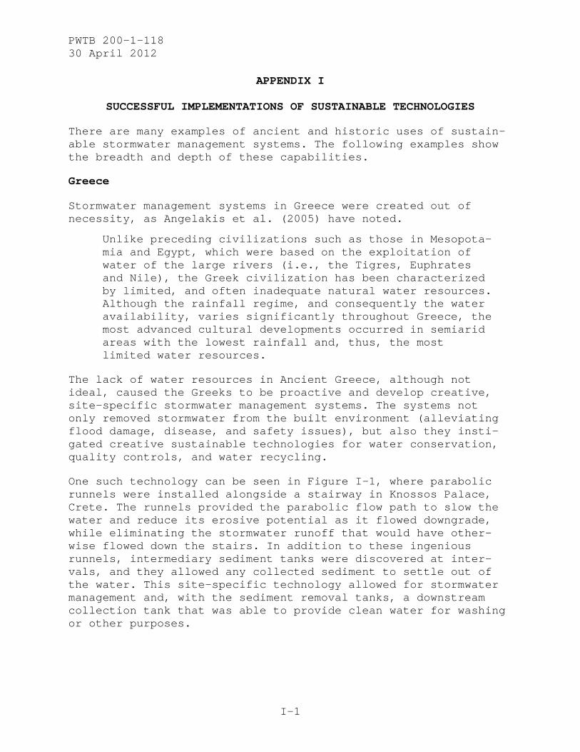
PWTB 200-1-118 30 April 2012
I-1
APPENDIX I
SUCCESSFUL IMPLEMENTATIONS OF SUSTAINABLE TECHNOLOGIES
There are many examples of ancient and historic uses of sustain-able stormwater management systems. The following examples show the breadth and depth of these capabilities.
Greece
Stormwater management systems in Greece were created out of necessity, as Angelakis et al. (2005) have noted.
Unlike preceding civilizations such as those in Mesopota-mia and Egypt, which were based on the exploitation of water of the large rivers (i.e., the Tigres, Euphrates and Nile), the Greek civilization has been characterized by limited, and often inadequate natural water resources. Although the rainfall regime, and consequently the water availability, varies significantly throughout Greece, the most advanced cultural developments occurred in semiarid areas with the lowest rainfall and, thus, the most limited water resources.
The lack of water resources in Ancient Greece, although not ideal, caused the Greeks to be proactive and develop creative, site-specific stormwater management systems. The systems not only removed stormwater from the built environment (alleviating flood damage, disease, and safety issues), but also they insti-gated creative sustainable technologies for water conservation, quality controls, and water recycling.
One such technology can be seen in Figure I-1, where parabolic runnels were installed alongside a stairway in Knossos Palace, Crete. The runnels provided the parabolic flow path to slow the water and reduce its erosive potential as it flowed downgrade, while eliminating the stormwater runoff that would have other-wise flowed down the stairs. In addition to these ingenious runnels, intermediary sediment tanks were discovered at inter-vals, and they allowed any collected sediment to settle out of the water. This site-specific technology allowed for stormwater management and, with the sediment removal tanks, a downstream collection tank that was able to provide clean water for washing or other purposes.

PWTB 200-1-118 30 April 2012
I-2
Figure I-1. Part of restored stairway with parabolic
runnels in Knossos Palace, Crete (Angelakis et al. 2005).
Figure I-2 shows a second illustration of the stormwater manage-ment system in Crete. This figure shows a construction section of a road incorporating a stone masonry sewer. This sewer is a street stormwater collection and channeling device, similar to today’s source control techniques. This stormwater sewer is unique because its pervious paving construction allows water to flow in. The bottom of the sewer channel, however, is not paved; the bottom remains open to the soil below. This design allows for more economical construction by eliminating the need to pave the channel bottom. The design slows water velocity through the naturally rough soil surface, and it allows groundwater recharge and infiltration through the subsurface.

PWTB 200-1-118 30 April 2012
I-3
Figure I-2. Top: Drain detail in Katagogeion’s
court in Cassope (Angelakis et al. 2005). Bottom: Stone sewer under paved street in Dion,
Macedonia (shown in Angelakis et al. 2005, originally from Karadedos 2000).
Sinagua in Northern Arizona
A second example of ancient sustainable stormwater management is found with the Sinagua people in Northern Arizona. The Sinagua civilization peaked in the twelfth and thirteen centuries A.D., with a gradual growth and decline from the seventh to fifteenth centuries (Anthropology Laboratories n.d.). In this region of Arizona, the environment provided the Sinagua culture with a challenging set of problems. Soils were thin, and the climate was hot. The Sinagua people, however, were very resourceful with water and created a dry-farming system for maize, beans, and squash. In areas without sufficient surface water, the people were found to have created small ponds to catch rainwater (Figure I-3). When the ponds filled, there is evidence that they scooped the water into ceramic jars for storage. Four manmade reservoirs have been found, although more may have existed. The reservoirs were built by placing rocks and earth berms across shallow wash channels. So effective was the construction, these basins still function as rainwater collectors (LUHNA n.d.).
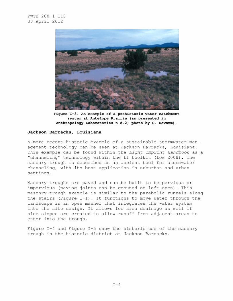
PWTB 200-1-118 30 April 2012
I-4
Figure I-3. An example of a prehistoric water catchment
system at Antelope Prairie (as presented in Anthropology Laboratories n.d.2; photo by C. Downum).
Jackson Barracks, Louisiana
A more recent historic example of a sustainable stormwater man-agement technology can be seen at Jackson Barracks, Louisiana. This example can be found within the Light Imprint Handbook as a “channeling” technology within the LI toolkit (Low 2008). The masonry trough is described as an ancient tool for stormwater channeling, with its best application in suburban and urban settings.
Masonry troughs are paved and can be built to be pervious or impervious (paving joints can be grouted or left open). This masonry trough example is similar to the parabolic runnels along the stairs (Figure I-1). It functions to move water through the landscape in an open manner that integrates the water system into the site design. It allows for area drainage as well if side slopes are created to allow runoff from adjacent areas to enter into the trough.
Figure I-4 and Figure I-5 show the historic use of the masonry trough in the historic district at Jackson Barracks.

PWTB 200-1-118 30 April 2012
I-5
Figure I-4. Linear masonry trough at Jackson Barracks, LA (Low 2008).
Figure I-5. Linear masonry trough at Jackson Barracks, LA (Low 2008).

PWTB 200-1-118 30 April 2012
I-6
Current Applications of Green Infrastructure
Portland, Oregon
The city of Portland has a comprehensive stormwater management “Grey to Green Infrastructure” initiative (Figure I-6) that was started in 2008 to “expand stormwater management techniques that mimic natural systems, protect and restore natural areas, and improve watershed health” (Portland Bureau of Environmental Services 2011a). This program is a 5-year, $55-million invest-ment to accelerate the implementation of Portland’s Watershed Management Plan (Portland Bureau of Environmental Services 2011b).
Figure I-6. Schematic graphic of Portland's “Grey to Green Infrastructure” initiative (Portland Bureau of
Environmental Services 2011a).

PWTB 200-1-118 30 April 2012
I-7
To achieve the Grey to Green initiative goals, Portland has established 5-year targets (Portland Bureau of Environmental Services 2011c), as listed below.
• adding 43 new acres of ecoroof
• planting 33,000 new yard trees and 50,000 new street trees
• restoring native vegetation on 350 more acres
• constructing 920 new green street facilities
• controlling the spread of new species of invasive plants on 800 acres and helping to “protect the best” park habitat
• replacing eight culverts that block fish passage
• purchasing and protecting 419 acres of high priority natural areas
This program is an example of an effective, integrated, city-wide, comprehensive approach to create a sustainable stormwater management system. With this initiative, Portland is a leader in stormwater management.
Portland has also developed an “Innovative Wet Weather Program” that is contributing to the city’s push to create and maintain a sustainable stormwater management system (City of Portland Envi-ronmental Services 2010). This program is funded by a $34-million grant from the EPA for over 25 demonstration projects including downspout disconnects, ecoroofs, green streets, infil-tration planters, pavement removal and tree planting, pervious pavement, rain gardens, vegetated planters, vegetated swales, and master planning.
Chicago, Illinois
In Appendix B, Chicago’s combined stormwater and sewer system was outlined as an example of the development of conventional stormwater management systems. Currently, the City of Chicago has multiple programs in place, with the intent of creating a sustainable urban environment using GI strategies. Retrofitting the way stormwater is managed is a central part of the city’s plans.
Chicago has created multiple initiatives and programs to provide a structured and multifaceted strategy for sustainability. The

PWTB 200-1-118 30 April 2012
I-8
broad and overarching Streetscape and Sustainable Design Program focuses on rehabilitating public rights-of-way (constituting 23% of the total acreage in Chicago) to “improve carbon emissions, reduce the urban heat island effect, implement stormwater man-agement best practices, reduce waste, improve human health and wildlife habitat and other numerous environmental benefits” (City of Chicago 2010a). Three components of this program are the Green Urban Design Framework Plan, the Green Alley Program, and the Sustainable Streets Initiative. Chicago has also imple-mented a Sustainable Backyard Program, which aims to involve residents and encourage modifications to private properties to help achieve an integrated green urban infrastructure.
The main goal of Green Urban Design Framework Plan is, “Maintain and improve upon Chicago’s urban design to optimize its environ-mental benefits for current and future generations.” This plan focuses on site design, public right-of-way, public landscapes, and indicators to evaluate the urban environment (i.e., all exterior surfaces) to preserve land, conserve and maintain clean water resources, improve air quality, and develop better quality of life within the city (Olsen and Berkshire 2007, 23).
Chicago’s Green Alley Program began in 2006 (Figure I-7) and is focused on rehabilitating the 13,000 public alleys stretching a combined 1,900 miles throughout Chicago. Before the program began, alleyways comprised 3,500 acres of impermeable surface. Progress was made in 2010, when only 20% of the alleyways remained unimproved and another 20% were in need of repairs (Attarian n.d., 8).
The Sustainable Streets Initiative focuses on reducing the heat island effect and is part of the EPA Heat Island Reduction Pro-gram. Efforts are in place to install and promote “cool and sustainable pavements.” Although the driving force is climate change, the project is incorporating many GI strategies for stormwater management. These strategies include maximizing land-scape opportunities and streetscape surface areas such as bioswales and rain gardens, installing permeable pavers, and increasing tree canopy cover.
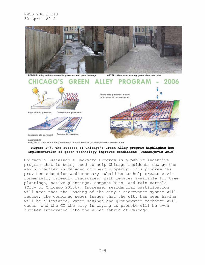
PWTB 200-1-118 30 April 2012
I-9
Figure I-7. The success of Chicago's Green Alley program highlights how
implementation of green technology improves conditions (Tanasijevic 2010).
Chicago’s Sustainable Backyard Program is a public incentive program that is being used to help Chicago residents change the way stormwater is managed on their property. This program has provided education and monetary subsidies to help create envi-ronmentally friendly landscapes, with rebates available for tree plantings, native plantings, compost bins, and rain barrels (City of Chicago 2010b). Increased residential participation will mean that the loading of the city’s stormwater system will reduce, the combined sewer issues that the city has been having will be alleviated, water savings and groundwater recharge will occur, and the GI the city is trying to promote will be even further integrated into the urban fabric of Chicago.

PWTB 200-1-118 30 April 2012
J-1
APPENDIX J
LESSONS LEARNED AND CONCLUSIONS
Lessons Learned
Army policy encourages the reduction of negative environmental impacts. In the case of stormwater management, the failure of conventional systems to provide environmental benefits has caused proven problems. Historically, stormwater management systems were dealt with in a conventional manner on military installations, with water channeled into storm sewers that quickly conveyed the stormwater runoff offsite. This strategy encouraged heavy runoff, sediment loading, and increased down-stream pollutants.
As the Army moves toward enhancing and sustaining natural sys-tems, conventional stormwater systems are being replaced with GI, LID, and LI strategies – both in new developments and retro-fit projects. These sustainable technologies work with existing natural systems by encouraging infiltration, groundwater re-charge, and evaporation, and by reducing polluted runoff. The benefits of sustainable stormwater infrastructure extend beyond a responsible environmental management regime by providing aes-thetic and economic value.
Historic districts are important cultural resources on Army installations and are managed according to guidelines in the NHPA. While the NHPA encourages adaptive reuse of historic buildings, the landscape issue of incorporating sustainable stormwater infrastructure in historic districts presents many challenges for cultural resource managers. Because historic districts were originally sited with conventional stormwater management technologies, the integration of sustainable infra-structure has the potential to alter the historic character of the district. Sustainable stormwater technologies rely on vege-tation and site-specific environmental conditions to slow, re-tain, and control water through effective land management. Historic district landscapes generally are not planned with enhanced vegetative areas, as there is typically minimal vegeta-tion surrounding buildings (although at some sites large street trees are incorporated). Preservation planning prioritizes phys-ical elements that reflect a pre-established time period of significance. In the case of landscape modifications for storm-water management, decisions must be made intelligently and in consultation with all stakeholders. Understanding and document-

PWTB 200-1-118 30 April 2012
J-2
ing a historic district’s multiple contexts and historic changes to development layout will inform managers and planners on how to incorporate sustainable technologies while being able to retain historic characteristics. In this way, sustainable land-scape technologies can successfully be implemented into the fabric of historic districts.
Conclusions
• Understanding a historic district’s character-defining fea-tures, including landscape organization and land use, is es-sential. Care should be taken to retain these aspects in any new undertaking.
• Historic districts are culturally significant and to avoid compromising their character, consultation with all stakehold-ers must be incorporated into the GI/LID/LI stormwater plan-ning and selection process.
• Adverse effects can be avoided through LID practices that are small and site-specific. There is great flexibility for adapt-ing and integrating sustainable technologies into the historic character of a military installation.
• Communication between all stakeholders is essential for effec-tive integration among projects.
• Using GI strategies and technologies must involve environmen-tal context studies that allow designs to function properly once installed.
• Upkeep of installed technologies is relatively inexpensive and essential to maintaining proper function.
• If designed, installed, and maintained correctly, sustainable infrastructure can accommodate all stormwater events onsite and eliminate the need for conventional infrastructure.
• Cost savings can be substantial when a GI/LID/LI approach is used within a historic district. In historic districts where stormwater management systems are now economically neutral, cost-benefits are seen through improved natural and environ-mental economies.

PWTB 200-1-118 30 April 2012
K-1
APPENDIX K
REFERENCES
Adams, Michele. 2003. “Porous Asphalt Pavement with Recharge Beds: 20 Years and Still Working. Stormwater.” May-June 2003. Online access at http://www.stormh2o.com/may-june-2003/pavement-porous-bmps.aspx.
Advisory Council on Historic Preservation. 2002. “Section 106 Regulations Summary.” Last modified April 26, 2002. Accessed July 06, 2011. http://www.achp.gov/106summary.html
Alpine Limited. “Eco-friendly Home & Garden Products.” n.d. Accessed August 24, 2011. http://www.alpinelimited.net/.
American Concrete Industries. n.d. “Fire Cisterns by ACI.” Accessed August 24, 2011. http://www.americanconcrete.com/commercial/containment_ tanks/Cisterns.htm.
American Trails. 2009. “Resources and Library: Cool Trail Solutions - Wood Walkways: Low Boardwalks for Accessible Trails and Nature Walks - Planked Walk in Bible Park, Denver, CO.” Photo by Stuart Macdonald, December 4, 2009. Accessed August 23, 2011. http://www.americantrails.org/photoGalleries/cool/24-Low-Boardwalk-ADA-Accessible-Trail.html.
______. 2002. “Resources and Library: Cool Trail Solutions - Wood walkways: Low Boardwalks for Accessible Trails and Nature Walks - Two Steps Connect Planked Walk to Crushed Rock Trail, Mill Creek Canyon, Salt Lake City, UT.” Photo by Stuart Macdonald, June 2002. Accessed August 23, 2011. http://www.americantrails.org/photoGalleries/cool/24-Low-Boardwalk-ADA-Accessible-Trail.html.
Angelakis, A.N., D. Koutsoyiannis, and G. Tchobanoglous. 2005. “Urban Wastewater and Stormwater Technologies in Ancient Greece.” Water Research 39(1):210-220.
Anthropology Laboratories of Northern Arizona University. n.d.. “Ancestral Pueblo: Sinagua.” Accessed 6 July 2011 http://www2.nau.edu/d-antlab/Soutwestern%20Arch/Sinagua/sinagua.htm.
______. n.d. “Wupatki and Water.” Accessed 6 Jul 2011. http://jan.ucc.nau.edu/d-antlab/Wupatki/water.htm.
Attarian, Janet L. n.d. Chicago’s Sustainable Streets Pilot Project: Cool and Sustainable Pavements – US EPA Heat Island Reduction Program. http://www.epa.gov/heatisland/resources/pdf/5-Chicago-SustainableStreetsPilotProject-Attarian-Chicago.pdf.
Båckström, M., P. A. Malmqvist, and M. Viklander. 2002. Stormwater Management in a Catchbasin Perspective — Best Practices or Sustainable Strategies? Water Science Technol. 46(6-7):159-66. http://www.ncbi.nlm.nih.gov/pubmed/12380987.
PWTB 200-1-118 30 April 2012
K-2
Bark Boys Inc. 2009. “Products.” Accessed August 25, 2011. http://www.barkboys.net/products.htm.
Bay Area Stormwater Management Agencies Association (BASMAA). 1997. Start at the Source: Residential Site Planning and Design Guidance Manual for Stormwater Quality Protection. Palo Alto, CA: Tom Richman and Associates.
______. 1999. Start at the Source: Design Guidance Manual for Stormwater Quality Protection. Accessed 6 July 2011. http://www.scvurppp-w2k.com/pdfs/0203/c3_related_info/startatthesource/Start_At_The_Source_Full.pdf.
Bioengineering Group Inc. n.d. “University of Iowa Stormwater & Bioengineering Design, Iowa City, IA.” Project webpage accessed August 22, 2011. http://www.bioengineering.com/projects/view.php?id=41.
______. n.d. “Upper Connecticut River Habitat Restoration Plan, NH.” Project webpage accessed August 22, 2011. http://www.bioengineering.com/projects/view.php?id=43.
Boddingtons. 2011. “Grass Reinforcement Solutions – BodPave™ 85 Porous Grass Paving Grids / Permeable Pavement.” Accessed October 27, 2011. http://www.boddingtons.us/ground-reinforcement/porous-grass-pavers.htm.
City of Chicago. 2010a. “Transportation: Streetscapes and Sustainable Design. Last modified 2010. Accessed 6 July 2011. http://www.cityofchicago.org/city/en/depts/cdot/provdrs/streetscapes.html.
______. 2010b. “Chicago Sustainable Backyard Program.” Accessed 6 July 2011. http://www.cityofchicago.org/city/en/depts/doe/provdrs/nat_res/svcs/how_can_i_get_a_rainbarrelorcompostbinrebateform.html.
City of Portland, Environmental Services. 2010. “Sustainable Stormwater Management: Innovative Wet Weather Demonstration Projects.” Accessed 5 July 2011. http://www.portlandonline.com/bes/index.cfm?c=35941&a=119476.
City of Sturgis. 2011. “Low Impact Development: Porous Pavements.” Accessed October 27 2011. http://www.sturgismi.gov/information_lid.
Clark, Ray. 1997. “NEPA: The Rational Approach to Change.” In Environmental Policy and NEPA, edited by Ray Clark and Larry Canter, p 17. Baton Rouge, LA: St. Lucie Press.
Colorado Plateau; Land Use History of North America. “Water Development, Extraction, and Diversion”, n.d. Accessed July 5, 2011. http://www.cpluhna.nau.edu/Change/waterdevelopment2.htm.
Congress for the New Urbanism (CNU). 2011. “Light Imprint New Urbanism.” Accessed 16 August 2011. http://www.cnu.org/node/1209.

PWTB 200-1-118 30 April 2012
K-3
Contech Construction Inc. 2011. “CMP Detention and Infiltration.” Accessed August 24, 2011. http://www.contech-cpi.com/Products/Stormwater-Management/Detention-and-Infiltration/CMP-Detention-and-Infiltration.aspx.
Debo, Thomas N., and Andrew J. Reese. 1995. Municipal Stormwater Management. Boca Raton, FL: CRC Press, Inc.
______. 2003. Municipal Stormwater Management, Second Edition. Boca Raton, FL: CRC Press, Inc.
Decor Guide. 2011. “Brick Paver.” Accessed August 24, 2011. http://www.decorguide.tk/about/house-decoration/brick-paver.
Department of the Army (DA). 1981. Installation Design. Army Technical Manual (TM) 5-803-5. Available at http://www.wbdg.org/ccb/ARMYCOE/COETM/tm_5_803_5.pdf.
______. 2006. “Memorandum on Sustainable Design and Development Policy Update – SpiRiT to LEED Transition.” Washington, DC: Office of the Assistant Secretary of the Army, Installations and Environment, signed by Joseph W. Whitaker, Deputy Assistant Secretary of the Army. Accessed 15 August 2011. http://www.wbdg.org/pdfs/asaie_sdd_policy_upd.pdf.
______. 2007. Army Regulation (AR) 200-1: Environmental Protection and Enhancement. Accessed 6 July 2011. http://www.apd.army.mil/pdffiles/r200_1.pdf.
______. 2011. “Today’s Focus: Net Zero.” Stand-To! Last modified January 31, 2011. Accessed 6 July 2011. http://www.army.mil/standto/archive/2011/01/31/?s_cid=email.
Department of the Navy. 2007. “Memorandum on Department of the Navy Low Impact Development (LID) Policy for Storm Water Management.” Signed by B.J. Penn on 16 November. Accessed 15 August 2011. http://secnavportal.donhq.navy.mil/portal/server.pt/gateway/PTARGS_0_0_2426_302_37444_43/http%3B/portalcontent.donhq.navy.mil%3B7087/publishedcontent/publish/secnav_portal/dasn_e_/technology__energy_conservation__and_innovation/technology__energy_conservation__and_innovation_highlights/lid.pdf.
______. 2007. “Navy Announces Low-Impact Development Policy.” Story Number: NNS071205-06 on US Navy Website, released 5 December. Accessed 6 July 2011. http://www.navy.mil/search/display.asp?story_id=33692.
Energy Independence and Security Act of 2007. Accessed 6 July 2011. http://frwebgate.access.gpo.gov/cgi-bin/getdoc.cgi?dbname=110_cong_bills&docid=f:h6enr.txt.pdf.
Environmental Protection Agency (EPA). 1999. Low-Impact Development Design Strategies: An Integrated Design Approach. June 1999. Accessed 6 July 2011. http://www.epa.gov/owow/NPS/lid/lidnatl.pdf.

PWTB 200-1-118 30 April 2012
K-4
______. 2000a. Low Impact Development (LID): A Literature Review. EPA-841-B-00-005. Washington DC: US EPA Office of Water, Low Impact Development Center. Accessed 6 July 2011. http://www.epa.gov/owow/NPS/lid/lid.pdf.
______. 2000b. Constructed Wetlands Treatment of Municipal Wastewaters. EPA/625/R-99/010 (design manual). Cincinnati, Ohio: Office of Research and Development. Available at http://www.epa.gov/owow/wetlands/pdf/Design_Manual2000.pdf.
______. 2004. “Wetland Regulatory Authority: Regulatory Requirements.” In: The Wetland Fact Sheet Series. EPA843-F-04-001. http://www.epa.gov/owow/wetlands/pdf/reg_authority_pr.pdf.
______. 2007a. “Fact Sheet: Reducing Stormwater Costs through Low Impact Development (LID) Strategies and Practices.” Factsheet is based on EPA publication number 841-F-07-006. Last modified 13 January 2010. Accessed 23 May 2011. http://www.epa.gov/owow/NPS/lid/costs07/factsheet.html.
______. 2007b. “Curb Cuts in the Swales, Along with the Grade of the Lot, Encourage Water to Enter the Vegetated Swale.” Green Infrastructure Photos on Picasa - Jan 5, 2007. Accessed August 23, 2011. https://picasaweb.google.com/buildgreeninfrastructure/PortlandOR#5107163618707995538.
______. 2007c. “Emeryville, CA: Valley Gutters in the Alleyway of High Density Residential Development.” Green Infrastructure Photos on Picasa - July 2007. Accessed August 23, 2011. https://picasaweb.google.com/buildgreeninfrastructure/EmeryvilleCA#5103471544561266978.
______. 2007d. “Green Infrastructure Statement of Intent.” EPA and the National Association of Clean Water Agencies, Natural Resources Defense Council, Low Impact Development Center, Association of State and Interstate Water Pollution Control Administrators. Accessed July 6, 2011. http://www.epa.gov/npdes/pubs/gi_intentstatement.pdf.
______. 2008a. “Bioretention in Middle of Mt. Tabor School Parking Lot.” Green Infrastructure Photos on Picasa - Nov 16, 2008. Accessed August 23, 2011. https://picasaweb.google.com/buildgreeninfrastructure/PortlandOR#5272060731813459458.
______. 2008b. “Chicago” [bioretention swale]. Green Infrastructure Photos on Picasa - September 5, 2008. Accessed August 24, 2011. https://picasaweb.google.com/buildgreeninfrastructure/Chicago#5363923598549774434.
______. 2008c. “Eco-Roofs and Green Street Planters Below.” Green Infrastructure Photos on Picasa - Nov 16, 2008. Accessed August 23, 2011. https://picasaweb.google.com/buildgreeninfrastructure/PortlandOR#5279006396919610098.
PWTB 200-1-118 30 April 2012
K-5
______. 2008d. “Notice Stacked Parking.” Green Infrastructure Photos on Picasa - Nov 16, 2008. Accessed August 23, 2011. https://picasaweb.google.com/buildgreeninfrastructure/PortlandOR#5279005362836053234.
______. 2008e. “Portland, OR: Curb Extension Bioretention, Adjacent to School Property.” Green Infrastructure Photos on Picasa - November 16, 2008. https://picasaweb.google.com/buildgreeninfrastructure/PortlandOR#5272061980441325938.
______. 2008f. “Portland, OR: Tryon Creek ‘Running’ Through the Development. Well, It Hadn't Rained Recently...” Green Infrastructure Photos on Picasa - November 16, 2008. Accessed August 23, 2011. https://picasaweb.google.com/buildgreeninfrastructure/PortlandOR#5279000413168796098.
______. 2008g. “Sidwell Friends School, Washington DC: An Artistic Feature to Convey Water in the Waste Water Treatment System.” Green Infrastructure Photos on Picasa - October 24, 2008. https://picasaweb.google.com/buildgreeninfrastructure/SidwellFriendsSchoolWashingtonDC#5313768955405392770.
______. 2008h. “Sidwell Friends School, Washington DC: Terraced Blackwater Treatment System.”. Green Infrastructure Photos on Picasa - October 24, 2008. Accessed August 24, 2011. https://picasaweb.google.com/buildgreeninfrastructure/SidwellFriendsSchoolWashingtonDC#5313769048715949394.
______. 2008i. “Unnamed.” (Vegetated street corner with permeable paving and drains.) Green Infrastructure Photos on Picasa - Nov 25, 2008. Accessed August 23, 2011. https://picasaweb.google.com/buildgreeninfrastructure/NewColumbiaPortlandOregon#5347598465248370658.
______. 2008j. “Unnamed.” (Vegetated purification bed.) Green Infrastructure Photos on Picasa - Nov 16, 2008. Accessed August 23, 2011. https://picasaweb.google.com/buildgreeninfrastructure/PortlandOR#5279007030110689554.
______. 2008k. “Vegetated Swale Runs Length of Street.” Green Infrastructure Photos on Picasa – Nov 19, 2008. Accessed August 23, 2011. https://picasaweb.google.com/buildgreeninfrastructure/SeattleStreetEdgeAlternativesSEA#5279034783280336674.
______. 2008l. “Clarification on Which Stormwater Infiltration Practices/Technologies Have the Potential to be Regulated as ‘Class V’ Wells by the Underground Injection Control Program.” Memorandum 13 June 2008. Accessed 6 July 2011. http://www.epa.gov/npdes/pubs/memo_gi_classvwells.pdf.
______. 2008m. “Managing Wet Weather with Green Infrastructure: Action Strategy.” Accessed 6 July 2011. http://www.epa.gov/npdes/pubs/gi_action_strategy.pdf.
PWTB 200-1-118 30 April 2012
K-6
______. 2009a. “Cisterns in Basement of Friends Center.” Green Infrastructure Photos on Picasa - Jun 8, 2009. Accessed August 23, 2011. https://picasaweb.google.com/buildgreeninfrastructure/Philadelphia#5356833534284172242.
______. 2009b. “Policies and Resolutions.” Last modified 24 August 2009. Accessed 6 July 2011. http://cfpub.epa.gov/npdes/greeninfrastructure/information.cfm.
______. 2010a. “Integrating Green Infrastructure into Regulatory Programs.” Last modified 18 November 2010. Accessed 6 July 2011. http://cfpub2.epa.gov/npdes/greeninfrastructure/regulators.cfm.
______. 2010b. “Low Impact Development (LID) and Other Green Design Strategies.” Last modified 10 November 2010. Accessed 5 July 2011. http://cfpub.epa.gov/npdes/stormwater/menuofbmps/index.cfm?action=factsheet_results&view=specific&bmp=124.
______. 2010c. “Polluted Runoff (Nonpoint Source Pollution): Stormwater Management for Federal Facilities under Section 438 of the Energy Independence and Security Act.” Last modified 3 February 2010. Accessed 6 July 2011. http://www.epa.gov/owow/NPS/lid/section438/.
______. 2011a. “Clean Water Act (CWA).” Last modified 23 February 2011. Accessed 6 July 2011. http://www.epa.gov/agriculture/lcwa.html#National percent20Pollutant.
______. 2011b. “Clean Water Act Overview.” Last modified 28 January 2011. Accessed 6 July 2011. http://www.epa.gov/oem/content/lawsregs/cwaover.htm.
______. 2011c. “Managing Wet Weather with Green Infrastructure.” Last modified 4 January 2011. Accessed 6 July 2011. http://cfpub.epa.gov/npdes/home.cfm?program_id=298.
Executive Order (EO) 11593. 1971. “Protection and Enhancement of the Cultural Environment.” Signed by President Richard M. Nixon on May 13. Accessed 6 July. http://www.archives.gov/federal-register/executive-orders/1971.html.
EO 13148. 2000. “Greening the Government through Leadership in Environmental Management.” Signed by President William J. Clinton on April 21. Accessed 6 July 2011. http://ceq.hss.doe.gov/nepa/regs/eos/eo13148.html.
EO 13423. 2007. “Strengthening Federal Environmental, Energy, and Transportation Management.” Signed by President George W. Bush on January 26, 2007. Accessed 6 July 2011. http://edocket.access.gpo.gov/2007/pdf/07-374.pdf.
Firehock, Karen. 2010. A Short History of the Term Green Infrastructure and Selected Literature. Accessed 6 July 2011. http://www.gicinc.org/PDFs/GI%20History.pdf.

PWTB 200-1-118 30 April 2012
K-7
Fuss & O’Niell. 2010. Technical Memorandum 4: Low Impact Development Guidelines and Standards. December 2010. Partners for the Connecticut Low Impact Development and Stormwater General Permit Evaluation. Accessed 6 July 2011. http://www.ct.gov/dep/lib/dep/water/nps/swgp/tm4_lid_guidelines_standards.pdf.
Golfmak, Inc. “How to Build a French Drain,” N.d. Accessed August 24, 2011. http://www.golfmak.com/french-drain.htm.
GRAF. 2011. “Rainwater Harvesting: Tanks Underground.” Accessed September 8, 2011. http://www.graf-water.com/rainwater-harvesting/tanks-underground.html.
GroundTradesXchange. 2008. “Another Kind.” forum link posted by “4seasons,” December 31, 2008. Accessed August 24, 2011. http://www.groundtradesxchange.com/forums/hardscaping/5275-calibrated-natural-stone-pavers.html#post60460.
Harris, Susan. 2007. “Delawning My Own Garden,” 2007. Sustainable Gardening Website, accessed August 24, 2011. http://www.sustainable-gardening.com/plants/lawn-substitutes/delawning-my-own-garden.
Hawkey, Jane. 2010. “Motorcyclist on Fire Road, British Columbia, Canada.” IAN Image Library. Accessed August 24, 2011. http://ian.umces.edu/imagelibrary/displayimage-6517.html.
Hawkey, Jane. 2009. “Wetlands, Adirondack Mountains of Upstate NY.” IAN Image Library, accessed August 24, 2011. http://ian.umces.edu/imagelibrary/displayimage-5971.html.
Hegg, Daniel. 2008. “Project 012: Project Urban Rain Garden.” Good: Environment Blog, accessed 6 July 2011. http://www.good.is/post/project-012-project-urban-raingarden/.
Hughes, Brian. Bob Sikes Airport Taxiway project underway. Crestview News Bulletin, Freedom Communications, June 08, 2011. Accessed August 22, 2011. http://www.crestviewbulletin.com/sections/article/gallery/?pic=0&id=14401.
Isabel. 2010. “Rock-Sequoia-Prunus-Stone - Calverley Grounds on a Wet and Windy Day ...” Blog entry Sunday, October 17, 2010. Accessed August 24, 2011. http://rocksequoiaprunusstone.blogspot.com/2010_10_01_archive.html.
Innovative Stormwater Management Practices (ISMP).n.d. “An Online Database and Showcase of Low Impact Development Practices in Ontario. http://iswm.ca/.
______. 2010. Image from York University within the CVC & TRCA Low Impact Development Stormwater Management Planning and Design Guide. 2010. Accessed Aug 17, 2011. http://www.iswm.ca/technologies.php.
PWTB 200-1-118 30 April 2012
K-8
Karadedos, G. 2000. Yδραυλικές γνώσεις και τεχνoλoγία–H περίπτωση τoυ Δίoυ (Hydraulic knowledge and technology – The Dion case). In Yδάτινες Σχέσεις–To Nερó ως Πηγή Zωής κατά την Aρχαιóτητα (Aquatic Relationships–Water as Source of Life in the Antiquity), C. Soueref, Ed. Thessalonike, Greece: University Studio Press (in Greek). http://www.sciencedirect.com/science/article/pii/S0043135404004397#bbib22.
Karimipour, Shohreh. n.d. “Going Green with the NYS Stormwater Design Standards.” New York State Department of Environmental Conservation (NYSDEC). Accessed 5 July 2011. ftp://ftp.dec.ny.gov/dow/stormdocuments/GIUpdateWorkshop/GI-RR-rollout-0216bw.pdf.
______. 2010. Going Green with the NYS Stormwater Design Standards. NYSDEC. Accessed 6 July 2011. http://www.cdrpc.org/Workshops/2010-10-04_DEC-DesignManualPresentation1.pdf.
KK Manhole & Gratings Co. Pvt. Ltd. n.d. “Fence, Bollards, and Tree Guards.” Accessed August 22, 2011. http://www.kkindia.com/pdf/treesurround.pdf.
Land Use History of North America (LUHNA): Colorado Plateau. n.d. “Water Development, Extraction, and Diversion.” Accessed 5 July 2011. http://www.cpluhna.nau.edu/Change/waterdevelopment2.htm.
Landscape Architecture Foundation. n.d. “Ruth Mott Foundation Gilkey Creek Relocation and Restoration Project.” Website last updated 2011. Accessed August 22, 2011. http://lafoundation.org/research/landscape-performance-series/case-studies/case-study/134/.
Landscape Drainage Solutions Inc. 2003. Photograph of Riprap Channel. Accessed August 23, 2011. http://www.landscapedrainagesolutions.com/id109.html
Lewis, Tela. 2011. “Concrete Pipe Classifications.” Ehow website, July 08, 2011. Accessed August 22, 2011. http://www.ehow.com/info_8708571_concrete-pipe-classifications.html.
Loechl, Suzanne K., Samuel A. Batzli, and Susan I. Enscore. 2007. Guidelines for Documenting and Evaluating Historic Military Landscapes: An Integrated Landscape Approach. An AEC Technical Guideline prepared by USACERL. Available at http://aec.army.mil/usaec/cultural/milland.pdf.
Low Impact Development Center, Inc. 2004. Final Report for the Low Impact Development Master Plan for Anacostia Combined Sewer Overflow Outfall #006 and Surrounding Areas in Washington D.C. Submitted to National Fish and Wildlife Foundation, Washington, DC. Accessed 6 July 2011. http://www.lowimpactdevelopment.org/anacostia/pubs/nfwf006_Final%20Report.pdf.

PWTB 200-1-118 30 April 2012
K-9
Low, Thomas E. 2008. Light Imprint Handbook: Integrating Sustainability and Community Design. Charlotte, NC: New Urban Press.
McCuen, R. H. 1998. Hydrologic Analysis and Design. Englewood Cliffs, NJ: Prentice-Hall.
Monarch Stone International. 2009. “Cobblestone Collections.” Accessed August 24, 2011. http://monarchstone.net/our-products/landscape-stone/.
Nashville Stone. n.d. Nashville Crushed Stone/Crushed Rock/ Landscape Rock/ Landscape Stone. Accessed August 24, 2011. http://www.nashvillenaturalstone.com/crushed-stone.html.
National Environmental Policy Act of 1969, as amended. Accessed 6 July 2011. http://ceq.hss.doe.gov/nepa/regs/nepa/nepaeqia.htm.
National Historic Preservation Act of 1966, as amended through 2006. Accessed 6 July 2011. http://www.achp.gov/docs/nhpa%202008-final.pdf.
National Park Service. Secretary of the Interior’s Standards and Guidelines for Archeology and Historic Preservation (As Amended and Annotated). June 18, 2001. Accessed 6 July 2011. http://www.nps.gov/history/local-law/arch_stnds_1.htm
______. Section 110 of the National Historic Preservation Act (16 U.S.C. 470). April 24, 1998. Accessed 6 July 2011. http://www.nps.gov/history/hps/fapa_110.htm.
Natural Environment Research Council (NERC). Sustainable Drainage Systems (SuDS). Accessed August 22, 2011. http://www.bgs.ac.uk/suds/.
Natural Resources Conservation Service (NRCS). 1986. Urban Hydrology for Small Watersheds. Technical Release 55. Washington, DC: US Department of Agriculture, Natural Resources Conservation Service, Conservation Engineering Division.
NRCS 1997. National Engineering Handbook, Part 630 – Hydrology (previously NEH-4). Washington, DC: US Department of Agriculture, Natural Re-sources Conservation Service.
Novak, Celest A. 2008. “Pedestrian Friendly: Planting Trees and Celebrating Stormwater in Urban Areas,” McGraw Hill Construction Continuing Education. Accessed August 24, 2011. http://ceu.construction.com/article_print.php?L=149&C=469&P=6.
Office of the Assistant Secretary of the Army for Installations, Energy & Environment). 2010. Army Vision for Net Zero – Net Zero is a Force Multiplier. Accessed 6 July 2011. http://www.asaie.army.mil/Public/IE/doc/Net%20Zero%20White%20Paper%2014%20Dec%202010%20with%20graphics%20test%20%28Revised%29%202.pdf.

PWTB 200-1-118 30 April 2012
K-10
Olsen, Erik, and Michael Berkshire. 2007. Greening the Urban Environment: Chicago’s Approach, p 23. Accessed 5 July 2011. http://greentownconference.com/GreenTown2007OlsenBerkshire.pdf.
Parker Landscape and Drainage. n.d. “Foundation Plants, 10 Years After Installed.” Photo gallery – accessed August 23, 2011. http://www.sparker.info/gallery.html.
Portland Bureau of Environmental Services. 2011a. Grey to Green: Working Green for Clean Rivers. Accessed 6 July 2011. http://www.portlandonline.com/bes/index.cfm?c=47203.
______. 2011b. “Portland Watershed Management Plan.” Accessed 6 July 2011. http://www.portlandonline.com/bes/index.cfm?c=38965.
______. 2011c. “What is Grey to Green?” Accessed 6 July 2011. http://www.portlandonline.com/bes/index.cfm?c=47203&a=321331
______. 2011d. “Green Streets: SW 12th Avenue Green Street.” Last modified 2011. Accessed August 22, 2011. http://www.portlandonline.com/bes/index.cfm?a=123776&c=45386.
Portland Cement Association. “Concrete Thinking for a Sustainable World – Applications – Water Infrastructure – Store, Move, and Treat Water. 2011. Accessed August 22, 2011. http://www.concretethinker.com/applications/Water-Infrastructure.aspx.
Prince George’s County, Maryland. 1999. Low-Impact Development Design Strategies: An Integrated Design Approach. Largo, MD: Department of Environmental Resources, Programs and Planning Division. Accessed 5 July 2011. http://www.epa.gov/owow/NPS/lid/lidnatl.pdf.
Professional concrete. 2010. “Designing Your Concrete Project – Tips from the Atlanta Concrete Specialist – Designing your Atlanta Concrete Project. Accessed August 24, 2011. http://pcofga.com/designing-your-concrete-project-tips-from-the-atlanta-concrete-specialist/.
Public Buildings Cooperative Use Act of 1976. October 18, 1976. Accessed 6 July 2011. http://www.gsa.gov/graphics/pbs/Coop_Use_Act_of_1976.pdf.
RainBarrelSource.com. 2011. “Plastic Rain Barrels - RTS 214 gal. Plastic Above Ground Rainwater Collecting Tank System.” Accessed October 27, 2011. http://www.rainbarrelsource.com/rain-barrels/rain-barrels/rts214galloncollectingtankmudbrown.cfm.
River Sands Pty Ltd, “Bulk Specialty Sands and Gravels, Bioretention Sand & Gravel Bends,” 2010. Accessed August 25, 2011. http://www.riversands.com.au/bulk-specialty-sands.
Roberts, L. Jolly. 2009. Photograph of a stone swale. Accessed August 22, 2011. http://www.flickr.com/photos/jollyroberts/3779879818/.
______. 2009. Photograph of a riprap swale. Accessed August 22, 2011. http://www.flickr.com/photos/jollyroberts/3779878290/.

PWTB 200-1-118 30 April 2012
K-11
Rutgers Cooperative Extension Water Resources Program. 2009. “South Harrison Township Elementary School Vegetated Swale.” Accessed August 22, 2011. https://picasaweb.google.com/100345168382178748048/SouthHarrisonTownshipElementarySchoolVegetatedSwale#5503475383488037650.
Smythe, R. B. 1997. “The Historical Roots of NEPA.” In Environmental Policy and NEPA: Past, Present, and Future, edited by Ray Clark and Larry Canter, p 12. Boca Raton, FL: St. Lucie Press.
Splash Splash. n.d. “Stormwater Design Components: Grassed Swale, Technical Standards for Grassed Swales.” Accessed August 22, 2011. http://www.abbey-associates.com/splash-splash/extra_jpegs/VEGETATED_SWALE-01%20copy.jpg.
______. n.d. “Landscape Design Components: Street Wall and Foundation Plantings.” Accessed August 22, 2011. http://www.abbey-associates.com/splash-splash/landscape_design_components.html.
State of Delaware. n.d. “What is the Stormwater System?” Accessed on August 24, 2011. http://www.deldot.gov/stormwater/description.shtml.
Sustainable Cities™. n.d. “Upton: Drainage Scheme Makes for Peace of Mind in Urban Expansion.” Accessed August 25, 2011. http://sustainablecities.dk/en/city-projects/cases/upton-drainage-scheme-makes-for-peace-of-mind-in-urban-extension.
Tanasijevic, Jovan. 2010. Paving, Paving Everywhere. Not a Drop Will Sink.: The Potential of Green Alleys. Architecture Boston. Volume 13 No. 13. Accessed July 5, 2011. http://architectureboston.com/2010/08/05/paving-paving-everywhere-not-a-drop-will-sink/.
Tanks a Lot. n.d. “Why Choose Steel Water Tanks?” Accessed August 24, 2011 http://www.tanksalot.co.nz/.
Tanski, J. “Safe Clean Boating – Stormwater Runoff Best Management Practices for Marinas: A Guide for Operators - STORMWATER TREATMENT BMPs.” Prepared for Sea Grant Northeast: New York Sea Grant Extension Program, Cornell Cooperative Extension. As presented in: Controlling Urban Runoff: A Practical Manual for Planning and Designing Urban BMPs (1987) by Thomas R. Schueler (available from the Metropolitan Washington Council of Governments, 777 North Capital Street N.E., Suite 300, Washington D.C. 20002-4201. Phone: (202) 962-3256).
TheGrowSpot.com. 2007. “Vertical Gardens - Living Walls (Marché des Halles in Avignon).” Photos posted by “smgardener, Grounds Keeper.” November 15, 2007. Accessed August 23, 2011. http://www.thegrowspot.com/know/f5/vertical-gardens-living-walls-53838.html.
The Rain Well. n.d. The Rain Well ™ Products, Subterranean Fixed Capacity Poly Cisterns. Accessed August 24, 2011. http://www.therainwell.com/Products.html.

PWTB 200-1-118 30 April 2012
K-12
Thomas, Jane. 2006a. “Harris Creek, a Tributary of the Choptank River.” File 826/1119, Integration & Application Network, July 7, 2006. Accessed August 23, 2011. http://ian.umces.edu/imagelibrary/displayimage-1032.html.
______. 2006b. “Looking Along Trappe Creek Towards Newport Bay.” File 244/268, Integration & Application Network, May 22, 2006. Accessed August 23, 2011. http://ian.umces.edu/imagelibrary/displayimage-470.html.
______. 2007. “Native garden in Amos Garrett Park,” May 16, 2007. Accessed August 23, 2011. http://ian.umces.edu/imagelibrary/displayimage-1445.html.
Top Asphalt Limited. n.d. “Commercial Block Paving and Flagging.” Accessed August 24, 2011. http://www.topasphalt.co.uk/block_paving_flagging.html.
Total Earthworks & Environmental Services, n.d. “Construction & Maintenance of Gravel Roads, Tracks, Road Batters and Walking Trails.” Accessed August 23, 2011. http://www.totalearthworks.com.au/Dirt%20roads.html.
Town, Lisa. Inspiration Wall: Water – Urban Water Conveyance, Frieburg Bächle. Friday July 16th 2010. Accessed August 22, 2011. http://lisastown.com/inspirationwall/category/water/
Unified Facilities Criteria (UFC). 2010. Low Impact Development. UFC 3-210-10, November 15, 2010 (supersedes UFC 3-20-10 dated 25 October 2004). US Army Corps of Engineers, Naval Facilities Engineering Command, and Air Force Civil Engineering Support Agency. Available at http://www.wbdg.org/ccb/DOD/UFC/ufc_3_210_10.pdf.
United Nations Environment Programme (UNEP). 1994. UNEP: Guidelines for Sediment Control Practices in the Insular Caribbean - Figure 6. Typical riprap-lined channel cross-sections.” CEP Technical Report No. 32 UNEP Caribbean Environment Programme, Kingston, Jamaica, 1994. Accessed August 22, 2011. http://www.cep.unep.org/pubs/Techreports/tr32en/fig6.gif.
US Soil Conservation Service. 1987. Urban Hydrology for Small Watersheds. Technical Release 55. Washington, DC: US SCS. Accessed 5 July 2011. http://www.cpesc.org/reference/tr55.pdf.
Vancouver Modern Residential Blog. 2010. West Vancouver Modern Home Tour 2010, Wood Block Paving in the Central Courtyard.” July 18, 2010. Accessed on August 25, 2011. http://drkdesign.wordpress.com/category/homes/page/4/.
Vermont League of Cities and Towns & Vermont’s Regional Planning Commissions. n.d. Designing Innovative Stormwater Systems Using Low Impact Development (LID). Accessed 6 July 2011. http://207.136.225.68/Downloads/Other/Designing_Stormwater_Systems_ Using_LID.pdf.

PWTB 200-1-118 30 April 2012
K-13
Vision Design Collaborative (VDC) Green. 2010. “Permeable Pavement Systems.” Friday, September 10, 2010. Accessed October 19, 2011. http://vdcgreen.blogspot.com/2010/09/permeable-pavement-systems-just.html.
Wallbarn. 2011. “Hardwood Timber Decking, Timber Decking Installed Quickly and Easily onto Roofs, Balconies, and Terraces, Using Wallbarn Timber Tiles.” Accessed on August 25, 2011. http://www.wallbarn.com/hardwood-timber-decking-tiles.htm.
Walsh, Brian. 2011. “How Do I Choose the Best Concrete Pavers?” Ehow.com Article, March 23, 2011. Accessed August 24, 2011. http://www.ehow.com/info_8099626_do-choose-concrete-pavers.html.
Water Environmental Research Foundation (WERF). 2007a. Overcoming Obstacles. Accessed 7 July 2011. http://www.werf.org/livablecommunities/pdf/obstacles.pdf.
______. 2007b. Green Infrastructure Design Considerations. Accessed 7 July 2011. http://www.werf.org/livablecommunities/pdf/design.pdf.
______. 2009a. Basic Principles. Accessed 6 July 2011. http://www.werf.org/livablecommunities/tool_principles.htm.
______. 2009b. Retrofit Challenges. Accessed 6 July 2011. http://www.werf.org/livablecommunities/toolbox/retrofit_chal.htm.
Wicks, Caroline. Drainage ditch in an agricultural field near Ruthsburg, MD. March 24, 2008. Accessed August 23, 2011. http://ian.umces.edu/imagelibrary/displayimage-2529.html.
Wilson, Ward. 2009. “Mt. Airy Rain Catchers Rain Garden - Type A, with Underdrain.” Ward Wilson’s Gallery – Green Infrastructure, June 11, 2009. Accessed October 25, 2011. https://picasaweb.google.com/runoffengineer/GreenInfrastructure#5494571955208540386.
Woerner, J. 2006. “Canals and Homes off Roy Creek in Assawoman Bay. IAN Image Library, June 5, 2006. Accessed August 25, 2011. http://ian.umces.edu/imagelibrary/displayimage-535.html.

PWTB 200-1-118 30 April 2012
L-1
APPENDIX L
INTERVIEW LIST
The following people were interviewed for this work, and the authors gratefully recognize their knowledge and contributions to this PWTB.
Beardsley, Robert. Historic Architect, Fort Leavenworth, KS. Interview with authors. May 24, 2011.
Denfeld, Duane, PhD. Architectural Historian, Joint Base Lewis-McChord. Interview with authors. May 19, 2011.
Michael, Michelle. Architectural Historian, NAVFAC SE. Interview with authors. May 24, 2011.
Rector, Matthew. Historic Preservation Specialist, Fort Knox, KY. May 3-4, 2011.
Tagg, Martyn at Fort Huachuca, AZ. Personal correspondence: Interview with authors. June 3, 2011.

PWTB 200-1-118 30 April 2012
M-1
APPENDIX M
ACRONYMS AND ABBREVIATIONS
Term Spellout
AR Army Regulation
BMP best management practice
CECW Directorate of Civil Works, US Army Corps of Engineers
CEMP-CE Directorate of Military Programs, US Army Corps of Engineers
CERL Construction Engineering Research Laboratory
CFR Code of the Federal Regulations
CSO combined sewer overflow
CWA Clean Water Act
DA Department of the Army
DoD Department of Defense
DON Department of the Navy
DPW Directorate of Public Works
EA environmental assessment
EIS environmental impact statement
EPA Environmental Protection Agency; also USEPA
ERDC Engineer Research and Development Center
GI green infrastructure
HQUSACE Headquarters, US Army Corps of Engineers
LEED Leadership in Energy and Environmental Design
LI light imprint
LID low impact development
NHPA National Historic Preservation Act
NHL National Historic Landmark

PWTB 200-1-118 30 April 2012
M-2
Term Spellout
NPDES National Pollutant Discharge Elimination System
NRHP National Register of Historic Places
PDF portable document file
POC point of contact
PWTB Public Works Technical Bulletin
ROI return on investment
SEA Street Edge Alternatives (Project)
SHPO State Historic Preservation Office
TARP Tunnel and Reservoir Program
TMDL total maximum daily loads
URL universal resource locator
USACE US Army Corps of Engineers
USSCS US Soil Conservation Service
WBDG Whole Building Design Guide
WERF Water Environmental Research Foundation

(This publication may be reproduced.)