
PUBLIC WORKS STANDARD SPECIFICATIONS FOR ......PUBLIC WORKS STANDARD SPECIFICATIONS FOR CONSTRUCTION...
281
PUBLIC WORKS STANDARD SPECIFICATIONS FOR CONSTRUCTION June 2014 Redline Changes Effective October 2017 The following redline revisions are for effective letting dates October 2017 and beyond. Revisions are included for the following Sections: 01300, 01385, 01500, 600, 603, 611, 630, 632, 634, 635, 639, 650, 652, 654, 660, 663, 665, 671, 676, and 700.
Transcript of PUBLIC WORKS STANDARD SPECIFICATIONS FOR ......PUBLIC WORKS STANDARD SPECIFICATIONS FOR CONSTRUCTION...

PUBLIC WORKS STANDARD
SPECIFICATIONS FOR CONSTRUCTION
June 2014 Redline Changes Effective
October 2017
The following redline revisions are for effective
letting dates October 2017 and beyond.
Revisions are included for the following
Sections: 01300, 01385, 01500, 600, 603, 611,
630, 632, 634, 635, 639, 650, 652, 654, 660, 663, 665, 671, 676, and 700.

Table of Contents
07/21/2017 Table of Contents-1
Hillsborough County utilizes the latest FDOT Standard Specifications for Road and Bridge Construction with the following additions and/or exceptions. Hillsborough County Division I Standard Specifications 01010 Summary of Work 01015 Project Representative 01020 Mobilization 01030 Construction Equipment 01035 Prosecution and Progress 01040 Control of the Work 01070 Abbreviations and Definitions 01091 Reference Specifications 01200 Meetings and Conferences 01300 Contractor Submittals 01310 Bar Chart Schedule 01311 CPM Construction Schedule 01312 Measurement and Payment 01385 Color Audio Video Construction Record 01400 Quality Control / Assurance 01500 Maintenance of Traffic 01510 Temporary Construction Utilities 01530 Protection of Existing Facilities 01550 Access and Temporary Access Provisions 01560 Temporary Environmental Controls 01590 Field Offices, Equipment and Services 01600 Materials and Material Storage 01700 Completion, Start-up and Closeout Hillsborough County Standard Specifications to be used in lieu of corresponding latest FDOT Standard Specifications for Road and Bridge Construction: 204 Graded Aggregate Base 283 Reclaimed Asphalt Pavement Base 320 Hot Bituminous Mixtures; Plant, Methods and Equipment 327 Milling of Existing Asphalt Pavement 330 Hot Bituminous Mixtures General Construction Requirements 334 Superpave Asphalt Concrete 336 Asphalt Rubber Binder 337 Asphalt Concrete Friction Courses 341 Asphalt Rubber Membrane Interlayer 430 Pipe Culverts 901 Coarse Aggregate 902 Fine Aggregate 916 Bituminous Materials 919 Ground Rubber Tire 931 Metal Accessory Materials for Concrete Pavement and Concrete Structures

Table of Contents
07/21/2017 Table of Contents-2
Hillsborough County Standard Specifications for Traffic Signals to be added or supplemented to the corresponding latest FDOT Standard Specifications for Road and Bridge Construction: 600 Traffic Signal Overview 603 General Requirements for Installation and Evaluation of Traffic Control Equipment
and MaterialTraffic Control Signals and Devices 611 Signal Installation Acceptance Procedures for Traffic Control Signals and Devices 620 Signal Installation Grounding and Lighting Protection 630 Conduit 632 Signal and Interconnect Cable 634 Span Wire Assembly 635 Pull, Splice, and Junction Boxes 639 Electrical Power Service Assemblies 650 Vehicular Traffic Signal Assemblies 652 24/7 Solar Flashing Beacon Assembly 653 Pedestrian Signal Assemblies 654 Mdblock Crosswalk Enhancement Assemblies 660 Inductive Loop DetectorsVehicle Detection System 662 Emergency and Low Priority Control Preemption DetectionSignal Priority and
Preemption Systems 665 Pedestrian Detector AssemblyDetection System 670 Traffic Controller AssemblyAssemblies 671 Traffic Controllers 676 Controller Cabinet Assemblies 699 Internally Illuminated Signs 700 Highway Signing
- End of Section -

Section 01010 - Summary of Work
07/21/2017 Summary of Work Page 01010-1
01010-1 General Descriptions of Portions of The Work 01010-1.01 Sequencing And Scheduling Constraints: Schedule and perform the WORK in
such a manner as to result in the least possible disruption to the public's use of roadways, driveways, and utilities. Deliver notice to adjacent property occupants (private and public) and to the PROJECT MANAGER of all planned disruptions to roadways, driveways, and utilities ten days in advance of the disruption.
01010-1.02 Labor Employed: All labor employed by the CONTRACTOR and his
Subcontractors for work on the project shall work in harmony with and be compatible with all other labor being used by CONTRACTORs now or hereafter on the site of the WORK covered by this Contract.
01010-1.03 Sanitary Provisions: Provide and maintain, in a neat and sanitary condition, such
accommodations for the use of employees as are necessary to comply with the requirements and regulations of the State and Federal Government. Commit no public nuisance.
0101-1.04 Plant Quarantine Regulations: The U.S. Department of Agriculture and the
Florida Department of Agriculture and Consumer Services have issued quarantine regulations pertaining to control of the nematodes of citrus and other plant pests. Contact the Animal and Plant Health Inspection Service of the U.S. Department of Agriculture, and the Division of Plant Industry of the Florida Department of Agriculture and Consumer Services to ascertain any current restrictions regarding plant pests which may be imposed by these agencies. Keep advised of current quarantine boundary lines throughout the construction period.
These restrictions may affect operations in connection with such items as clearing, grubbing, earthwork, grassing and mulching, sodding, landscaping, and other items which might involve the movement of materials containing plant pests across quarantine lines.
Quarantine regulations and related information can be obtained from the following: Animal and Plant Health Inspection Service U.S. Department of Agriculture 3031 Lake Alfred Road Winter Haven, Florida 33881 Director, Division of Plant Industry Florida Department of Agriculture and Consumer Services Post Office Box 147100 Gainesville, Florida 32614-7100 01010-1.05 Introduction or Release of Prohibited Aquatic Plants, Plant Pests or Noxious
Weeds: Do not introduce or release prohibited aquatic plants, plant pests or noxious

Section 01010 - Summary of Work
07/21/2017 Summary of Work Page 01010-2
weeds into the project limits as a result of clearing, grubbing, earthwork, grassing and mulching, sodding, landscaping, or other such activities. Immediately notify the COUNTY upon discovery of any prohibited aquatic plants, plant pests or noxious weeds within the project limits. Do not move prohibited aquatic plants, plant pests or noxious weeds within the project limits or to locations outside of the project limits without permission of the COUNTY. All borrow material brought onto the project site shall be free of prohibited aquatic plants, plant pests or noxious weeds and their reproductive parts. Attention is directed to the Florida Administrative Code for the definition of prohibited aquatic plants, plant pests and noxious weeds.
01010-1.06 Compliance with Federal Endangered Species Act: The Federal Endangered
Species Act requires that the potential of any activity performed in conjunction with a highway construction project to impact an endangered Species be investigated prior to initiating such activity. If there is a potential impact on an endangered species, a biological assessment will be necessary to determine what measures are necessary to mitigate such impact. In the event that a biological assessment indicates that mitigation measures are necessary, the CONTRACTOR shall cooperate as necessary to comply with such measures.
01010-1.07 Air Pollution: Comply with the provisions of Chapter 403, Florida Statutes,
regarding control of air pollution. There will be no open burning operations allowed. 01010-1.08 Underground Pollutant Storage Tanks: CONTRACTORs removing
underground pollutant storage tanks must be certified by the Construction Industry Licensing Board as required by the Florida Statutes, regardless of exemptions allowed by the State. Disposition of the tanks and pollutants will be made in accordance with the requirements and regulations of any Local, State or Federal Agency having jurisdiction.
01010-1.09 Discovery of an Unmarked Human Burial: If an unmarked human burial is
discovered, all activity that may disturb the unmarked human burial shall cease immediately, and the PROJECT MANAGER shall be notified by the CONTRACTOR. Activity shall not resume until specifically authorized by the PROJECT MANAGER.
01010-1.10 Work or Structures in Navigable Waters of the U.S., Waters of the U.S., and
Waters of the State: In carrying out the WORK in the Contract, when under the jurisdiction of any environmental regulatory agency, comply with all regulations issued by such agencies and with all general, special, and particular conditions relating to construction activities of any and all permits issued to the COUNTY as though such conditions were issued to the CONTRACTOR. The CONTRACTOR is responsible for posting any permit placards in a protected location at the WORK site.
In case of any discrepancy between any permit condition and a requirement of the plans or a special provision; or a developmental, supplemental, or standard

Section 01010 - Summary of Work
07/21/2017 Summary of Work Page 01010-3
specification; the permit condition shall prevail. If the permit conditions require WORK or the furnishing of materials not specifically provided for in the basis of payment clause for a pay item contained in the proposal, such WORK or the furnishing of materials shall be considered to be included in the other items of WORK and is to be completed as part of the WORK. Special sequencing or scheduling of operations that may be required by permit conditions shall also be considered as part of the WORK.
Do not obstruct navigation channels without permission from the proper authority. Provide and maintain navigation lights and signals in accordance with the Federal requirements for the protection of the structure, of false work, and of navigation. In the event of accidental blocking of the navigation channel, the U.S. Coast Guard must immediately be notified by the CONTRACTOR of the blockage and upon removal of the blockage.
Where the WORK includes the excavation of a channel or other underwater areas to a required section, maintain the section against shoaling or other encroachment until final acceptance of the project.
01010-1.11 Dredging and Filling: The Florida Statutes require that all persons who engage in
certain dredge or fill activities in the State of Florida shall obtain a certificate of registration and shall keep accurate logs and records of all such activities so that natural resources may be protected and conserved. Details as to the application of this law should be obtained from the State.
01010-1.12 Control of the Contractor's Equipment Traffic Interference: Equipment, while it
is on or traversing a road or street, is not to unreasonably interfere with traffic. If traffic is unreasonably obstructed or accidents do occur, it may result in the COUNTY issuing a stop work order.
01010-1.13 Preservation of Property:
General: Preserve from damage all property along the line of work (or which is in the vicinity of or is in any way affected by the work) the removal or destruction of which is not called for by the plans. Special attention is directed to the protection of any geodetic monument, horizontal or vertical, located within the limits of construction. Failure to Restore Damaged Property: In case of failure on the part of the CONTRACTOR to restore such property, bridge, road or street, or to make good such damage or injury, the COUNTY may, upon 48 hours notice, proceed to repair, rebuild or otherwise restore such property, road or street as may be deemed necessary, and the cost thereof will be deducted from any monies due or which may become due the CONTRACTOR under the contract. Nothing in this clause shall prevent the CONTRACTOR from receiving proper compensation for the removal,

Section 01010 - Summary of Work
07/21/2017 Summary of Work Page 01010-4
damage or replacement of any public or private property, not shown on the plans, which is made necessary by alteration of grade or alignment and such WORK is authorized by the PROJECT MANAGER; provided that such property has not been damaged through fault of the CONTRACTOR, his employees or agents. Guardrail: All existing guardrail shall be protected against damage or displacement. Whenever such guardrail lies within the limits of construction, or wherever so directed by the PROJECT MANAGER due to exigencies of construction operations, the existing roadside guardrail shall be taken up by the CONTRACTOR, properly stored, and subsequently reset at the original location or, in the case of widened pavement or roadbed, at locations designated by the PROJECT MANAGER.
01010-1.14 Operations Within Railroad Right of Way: Notification to the Railroad Company: The CONTRACTOR shall give notification
to the Division Engineer or the Superintendent of the railroad company and to the COUNTY appropriately in advance of (minimum of 72 hours) his beginning of any operations within the limits of the railroad right of way, any operations requiring movement of employees, trucks or other equipment across the tracks of the railroad company at other than an established public crossing and any other WORK which may affect railroad operations or property.
Contractor's Responsibilities: Comply with whatever requirements an authorized representative of the railroad company deems necessary in order to safeguard the railroad's property and operations. Any damage, delay or injury and any suits, actions or claims brought on account of damages or injuries resulting from the operations within or adjacent to railroad company right of way shall be the CONTRACTOR's responsibility. Watchman or Flagging Services: Any protective services to insure the safety of railroad operations (watchman or flagman service) needed during the project are the CONTRACTOR's responsibility and should be incorporated into the bid price.
01010-1.15 CONTRACTOR's Responsibility for Work: Until acceptance of the WORK by
the COUNTY it shall be under the charge and custody of the CONTRACTOR and he shall take every necessary precaution against injury or damage to the WORK by the action of the elements or from any other cause whatsoever, arising either from the execution or from the nonexecution of the work. The CONTRACTOR shall protect, rebuild, repair, restore and make good, without additional compensation, all injury or damage to any portion of the WORK occasioned by any cause before its completion and acceptance. As an example of protection as indicated above, the CONTRACTOR shall provide manpower on the site during the cure period of concrete, such as sidewalks, to insure that the surface is not marred by passersby.

Section 01010 - Summary of Work
07/21/2017 Summary of Work Page 01010-5
The CONTRACTOR will not be held responsible for damage to any landscape items caused by an officially declared hurricane which occurs after the final acceptance of the entire work, but during any remaining portion of the 90-day establishment period.
01010-1.16 Special Traffic Measures: Provide all measures to ensure the safe passage of
pedestrian and vehicular traffic, including flagmen, lights, barricades, signs and off-duty policemen. One or two lanes of traffic shall be maintained during such work. Provide all necessary measures to ensure the safety of workmen and the general public. Temporary or permanent patches shall be in place by the end of the time period allowed for street cuts and two-way traffic shall be resumed.
01010-1.17 Normal Working Hours and Noise Control: Eliminate noise within the project
area to the extent possible. "Residential" type mufflers shall be installed on all gasoline and diesel engines. All local ordinances and regulations covering noise control shall be observed. Only emergency WORK shall be performed between the hours of 5 p.m. and 8 a.m., or on Saturdays, Sundays or COUNTY Holidays. Written permission shall be obtained from the PROJECT MANAGER prior to performing any WORK during these periods.
The normal work week shall be Monday through Friday, exclusive of COUNTY
holidays. The normal day shall be between the hours of 8:00 a.m. to 5:00 p.m. Schedule all WORK around these parameters. Any variation must be requested, in writing, 48 hours in advance with written approval from the PROJECT MANAGER.
01010-1.18 Salvage: All items encountered or produced during the execution of the WORK
which are not able to be incorporated into the WORK and as determined by the COUNTY's PROJECT MANAGER, are to be disposed of by the CONTRACTOR, with the exception of those items identified in the SPECIAL CONDITIONS. No materials shall be removed from the project site unless approved by the COUNTY's PROJECT MANAGER.
01010-1.19 Storage: Storage conditions shall be acceptable to COUNTY for all materials and
equipment not incorporated into the WORK but included in Applications for Payment. Such storage arrangements and conditions shall be presented in writing for COUNTY's review and approval and shall afford adequate and satisfactory security and protection. Off-site storage facilities shall be accessible to PROJECT MANAGER. The stored materials shall be insured for full value. Certificates of liability insurance coverage must be submitted to the PROJECT MANAGER with the request for payment. All arrangements and costs for storage facilities shall be paid by the CONTRACTOR, unless specifically designated in the Contract Documents to be furnished by the COUNTY.
01010-1.20 Lines and Grades:

Section 01010 - Summary of Work
07/21/2017 Summary of Work Page 01010-6
A. All WORK shall be done to the lines, grades, and elevations shown on the Drawings.
B. Basic horizontal and vertical control points will be established or designated
by the COUNTY as provided in the General Conditions. These points shall be used as datum for the WORK. The CONTRACTOR, through a licensed professional surveyor, shall verify all horizontal and vertical control points. All additional survey, layout, and measurement WORK shall be performed by CONTRACTOR as part of the WORK.
C. All field books, notes, and other data developed by CONTRACTOR in
performing the surveys required by the WORK shall be available to PROJECT MANAGER for examination throughout the construction period. All such data shall be submitted to PROJECT MANAGER with documentation required for final acceptance of the WORK.
D. CONTRACTOR shall keep PROJECT MANAGER informed, a
reasonable time in advance, of the times and places at which it wishes to do WORK, so that horizontal and vertical control points may be established and any checking deemed necessary by PROJECT MANAGER may be done with minimum delay to CONTRACTOR.
E. CONTRACTOR shall remove and reconstruct WORK which is improperly
located. 01010-1.21 Staging Area:
A. CONTRACTOR shall employ an area outside the limits of the site for location of office facilities, storage of materials and equipment, and staging area. The specific location shall be subject to approval of the PROJECT MANAGER and shall be coordinated to minimize interference with the operation of the existing facilities located therein and any other construction contracts containing WORK to be performed at this site. Submit a sketch of the proposed staging area showing such facilities to the PROJECT MANAGER at the preconstruction conference for consideration and approval. Any changes to same are to be resubmitted for approval.
B. The Site shall be returned to the original condition or better upon completion
of the WORK. C. Nothing in this AGREEMENT shall imply that the CONTRACTOR has
exclusive use of roadways or public and/or private land employed to perform the WORK.
01010 - 1.22 Prior to Digging: Contact the Hillsborough County Traffic Control Services
Section prior to digging where a traffic signal exists.

Section 01010 - Summary of Work
07/21/2017 Summary of Work Page 01010-7
01010 - 1.23 Provide 24-hour notice to Planning and Growth Management Department, Natural
Resources Team, Hillsborough County before working within 25 feet of existing trees.
01010 - 2.00 Basis of Payment: The cost of performing all WORK as described above shall be
included in the contract unit prices for the various items of WORK to which it is incidental.
- End of Section -

Section 01015 – Project Representative
07/21/2017 Project Representative Page 01015-1
01015-1.01 The PROJECT MANAGER may assign a PROJECT REPRESENTATIVE to
assist the PROJECT MANAGER And Or ENGINEER in the discharge of his/her duties. This PROJECT REPRESENTATIVE may be a Resident Engineer or a Construction Manager or other similar named person designated by the PROJECT MANAGER. PROJECT REPRESENTATIVE shall act as directed by and under the supervision of PROJECT MANAGER, and shall confer with PROJECT MANAGER regarding the actions to be taken. PROJECT REPRESENTATIVE's dealings in matters pertaining to the on-site WORK shall, in general, be only with PROFESSIONAL and CONTRACTOR. Dealings with Subcontractors, except in the event of an emergency, shall only be through or with the full knowledge of CONTRACTOR.
01015-2.01 Duties and Responsibilities:
Project Representative shall: A. Schedules.
1. Review the CONTRACTOR's initial schedule submittal which once approved by the PROJECT MANAGER will become the baseline schedule. Ensure the baseline schedule incorporates the original construction phasing plan and utility relocation schedules as per the CONTRACT and has a project completion date which matches the CONTRACT completion date. Modifications of the construction phasing plan by the CONTRACTOR must be approved by the PROJECT MANAGER and agreed to by all agencies and utilities impacted by the change.
2. Review and recommend to the PROJECT MANAGER action on
the progress schedule, schedule of submittals, and schedule of values prepared by CONTRACTOR.
B. Conferences. Attend preconstruction conference. Arrange a schedule of
progress meetings and other job conferences as required. Attend meetings; prepare, maintain, and circulate copies of minutes. Prepare and maintain action item logs from meetings.
C. Liaison.
1. Serve as PROJECT MANAGER's liaison with CONTRACTOR, working principally through CONTRACTOR's PROJECT MANAGER and Superintendent(s) and assist CONTRACTOR in understanding the intent of the Contract Documents.

Section 01015 – Project Representative
07/21/2017 Project Representative Page 01015-2
2. As requested by PROJECT MANAGER, assist in obtaining from COUNTY additional details or information when required at the job site for proper execution of the WORK.
3. Conduct periodic pre-construction phase meetings with
CONTRACTOR's personnel to review the upcoming phase of work to ensure the CONTRACTOR's personnel understand the scope of work as outlined in the plans and specifications, COUNTY's testing requirements, standards of construction, and can describe their internal quality control procedures for approval by the COUNTY.
D. Submittals.
1. Receive and record date of receipt of Submittals and samples, receive samples which are furnished at the site by CONTRACTOR, and notify PROFESSIONAL of their availability for examination or transmit to PROFESSIONAL as appropriate.
2. Advise PROFESSIONAL and CONTRACTOR immediately of the
commencement of any WORK requiring Submittal if the submission has not been approved by PROFESSIONAL.
3. Advise PROJECT MANAGER of adequacy and timeliness of the
review of submittals by the PROFESSIONAL. E. Review of WORK, Rejection of Defective WORK, Inspections, and Tests.
1. Conduct and record on-site observations of the WORK in progress to determine if the WORK is proceeding in accordance with the Contract Documents and that completed WORK will conform to the Contract Documents.
2. Report to PROJECT MANAGER whenever any WORK is
unsatisfactory, faulty, does not conform to the Contract Documents, is otherwise defective, does not meet the requirements of any inspections, tests or approvals required to be made, or has been damaged prior to final payment; and advise PROJECT MANAGER when WORK should be corrected or rejected or should be uncovered for observation, or requires special testing, inspection, or approval.
3. Verify that tests, equipment, and systems start-ups and operating and
maintenance instructions are conducted as required by the Contract Documents and in the presence of the required personnel, and that CONTRACTOR maintains adequate records thereof; observe, record, and report to PROJECT MANAGER appropriate details relative to the test procedures and start-ups.

Section 01015 – Project Representative
07/21/2017 Project Representative Page 01015-3
4. Accompany visiting inspectors representing public or other agencies
having jurisdiction over the Project, record the outcome of these inspections, and report to PROJECT MANAGER.
F. Interpretation of Contract Documents.
1. Prepare and maintain a Request for Information log. Record all
requests from the CONTRACTOR and note date of resolution. 2. Transmit PROFESSIONAL's clarifications and interpretation of the
Contract Documents to CONTRACTOR. G. Change Orders.
1. Prepare a Proposed Change Request for approval by PROJECT MANAGER, PROFESSIONAL and others as required to document the need and reasons for a change.
2. Prepare and maintain a Request for Proposal log. Record receipt of
each change proposal and monitor its disposition. 3. Evaluate CONTRACTOR's proposals for changes to the WORK and
report them with recommendations to PROJECT MANAGER. 4. Prepare negotiating plan and when requested, assist PROJECT
MANAGER in negotiating Change Orders with CONTRACTOR. 5. Prepare Change Order documentation, obtain necessary signatures
and certifications from CONTRACTOR and PROFESSIONAL, and forward package to PROJECT MANAGER.
H. Records.
1. Maintain at the job site orderly files for correspondence, reports of job conferences, Submittals, samples, reproductions of original Contract Documents including all Addenda, Change Orders, Field Orders, additional Drawings issued subsequent to the execution of the Agreement, and PROFESSIONAL's clarifications and interpretations of the Contract Documents, progress reports, and other Project related documents.
2. Prepare a daily report recording hours on the job site, weather
conditions, data relative to WORK activities, list of visiting officials and representatives of manufacturers, fabricators, suppliers, and distributors, inspections and tests performed, decisions, observations

Section 01015 – Project Representative
07/21/2017 Project Representative Page 01015-4
in general and specific observations in more detail as in the case of observing test procedures.
I. Reports.
1. Furnish PROJECT MANAGER periodic reports of progress of the WORK and CONTRACTOR's compliance with the approved progress schedule and schedule of Shop Drawing submissions.
2. Consult with CONTRACTOR in advance of scheduled major tests,
inspections, or start of important phases of the WORK. Advise PROJECT MANAGER and PROFESSIONAL of schedules for and changes to the schedule for testing.
3. Report immediately to PROJECT MANAGER upon the occurrence
of any accident. J. Payment Applications. Review Applications for Payment with
CONTRACTOR for compliance with the established procedure for their submission. Make recommendations to PROJECT MANAGER in relation to the schedule of values of WORK completed and materials and equipment delivered at the Site but not incorporated in the WORK.
K. Certificates, Maintenance, and Operation Manuals. During the course of the
WORK, verify that certificates, maintenance, and operation manuals and other data required to be assembled and furnished by CONTRACTOR are applicable to the items actually installed; and deliver this material to PROFESSIONAL for its review and forwarding the COUNTY prior to final acceptance of the WORK.
L. Record Drawings. Review the CONTRACTOR's Record Drawings
monthly to ensure CONTRACTOR is keeping adequate records as required. M. Completion
1. Prior to PROJECT MANAGER's issuance of a Certificate of Substantial Completion, assist PROJECT MANAGER in evaluating CONTRACTOR's punch list and developing an official punch list for Substantial Completion.
2. Conduct final inspection of the WORK in the company of
PROFESSIONAL, COUNTY, and CONTRACTOR and prepare a final list of items to be completed or corrected.

Section 01015 – Project Representative
07/21/2017 Project Representative Page 01015-5
3. Verify that all items on final list have been completed or corrected and make recommendations to PROJECT MANAGER concerning acceptance.
4. Prepare Transfer Document for execution and signature. Forward
complete document and attachments to the PROJECT MANAGER. 01015-2.02 Limitations of Authority: Except upon written instructions of PROJECT
MANAGER, PROJECT REPRESENTATIVE shall not: A. Authorize any deviation from the Contract Documents or approve any
substitute materials or equipment. B. Exceed limitations on PROJECT REPRESENTATIVE's authority as set
forth in the Contract Documents. C. Undertake any of the responsibilities of CONTRACTOR, Subcontractors,
or CONTRACTOR's superintendent, or expedite the WORK. D. Advise on or issue directions relative to any aspect of the means, methods,
techniques, sequences, or procedures of construction unless such is specifically called for in the Contract Documents.
E. Advise on or issue directions as to safety precautions and program in
connection with the WORK. F. Authorize COUNTY to occupy the Project in whole or in part. G. Take any action not specifically authorized either herein above or in any
separate contract between the COUNTY and the PROJECT REPRESENTATIVE.
- End of Section -

Section 01020 – Mobilization
07/21/2017 Mobilization Page 01020-1
01020 - 1.01 Definition and Scope:
A. Mobilization shall include the obtaining of all permits, insurance, and bonds; moving onto the site of all plant and equipment; furnishing and erecting plants, temporary buildings, and other construction facilities; all as required for the proper performance and completion of the WORK. Mobilization shall normally include, but not be limited to, the following principal items:
1. Move onto the site all plant and equipment required for first month operations. 2. Install temporary construction power, wiring, and lighting facilities. 3. Establish fire protection plan and safety program. 4. Secure construction water supply. 5. Provide field office trailers for CONTRACTOR and PROJECT
MANAGER complete with all specified furnishings and utility services, including telephones.
6. Provide on-site sanitary facilities and potable water facilities as
specified. 7. Arrange for and erect CONTRACTOR's work and storage yard and
employees' parking facilities. 8. All required insurance certificates and bonds. 9. Obtain all required permits. 10. Post all OSHA, EPA, Department of Labor, and all other required
notices. 11. Have CONTRACTOR's superintendent at the job site full time. 12. Erect project construction sign(s) as specified. 13. Construct, maintain, and restore temporary access and haul roads.
01020 - 1.02 Payment for Mobilization:
A. No payment for mobilization, or any part thereof, will be approved until all mobilization items listed above have been completed or updated as specified. On Lump Sum contracts, the CONTRACTOR shall spread the mobilization cost over the items included in the schedule of values. In Unit Price

Section 01020 – Mobilization
07/21/2017 Mobilization Page 01020-2
contracts where the COUNTY has not included a specific unit price item for mobilization in the Bid Proposal, the mobilization cost shall be spread over the items in the schedule of values.
B. Any identified lump sum Price for mobilization shall include the obtaining of
all items as noted in these Specifications and as required for the proper performance and completion of the WORK.
01020-2.01 Basis of Payment: Payment for mobilization will be made on an incremental basis
in accordance with the following:
1. No payment will be made until all required submittals are in and the field office (if any) is operational.
2. Percent of Original Allowable Percent
Contract Amount of the Lump Sum Earned Price for mobilization 5 25 10 50 25 75 50 100
The WORK and incidental costs specified as being covered under this Section will be paid for at the contract lump sum price for the item of Mobilization. When such item is included in the proposal, payment shall be made under:
Item No. 201020-001- Mobilization - lump sum.
The standard retainage will be applied to mobilization.
If a separate pay item is not in the contract for Mobilization then the costs for the items specified in this section shall be included in the individual pay items.
When more than one project or job (separate job number) is included in the contract, the above percentages shall apply separately to each job which has a separate pay item for Mobilization.
Where the Special Conditions have indicated that the CONTRACTOR will be reimbursed separately for the cost of obtaining performance and payment bonds, the CONTRACTOR will be paid the invoice price of the bonds(s) when the PROJECT MANAGER has been furnished with a certified copy of the invoice from the bonding company and the CONTRACTOR requests payment for such.
- End of Section -

Section 01030 – Construction Equipment
07/21/2017 Construction Equipment Page 01030-1
01030 - 1.01 Equipment: Unless shown on the plans or specifications, perform the WORK using equipment, tools, machinery, etc., of own choosing. Facilities to be constructed are adequate to support only their design loads in their completed construction stage. Any part of the facility which is damaged by the CONTRACTOR's equipment or procedures during construction shall be replaced or repaired as directed by the PROJECT MANAGER at the CONTRACTOR's expense.
01030 - 1.02 Equipment Condition And Approval:
A. Approval: All equipment to be used in construction of the project shall be on the site in due time prior to its need, in working condition, and shall be subject to approval or disapproval by the PROJECT MANAGER. Only factory recommended exhaust mufflers on internal combustion engines shall be used. Equipment which is disapproved shall be removed from the job, or altered or repaired, as required by the PROJECT MANAGER. The number of units, the sizes, etc., of the equipment on hand shall be adequate to insure completion of the WORK within the contract time.
B. Maintenance: Consistent with public interest, safety, and good practice, all
equipment, tools, and machinery used shall be maintained in a satisfactory working condition throughout the period they are on the job site. This will include adequate equipment maintenance procedures to insure the elimination of unnecessary noise caused by loose body parts on all construction equipment.
C. Tailgate Noise: Excessive tailgate banging by haul trucks will be prohibited. D. Stationary Equipment: All stationary equipment such as pumps,
compressors, generators, etc., shall be screened if that equipment is to operate beyond normal working hours. If it is feasible, this equipment shall be screened during normal working hours to reduce noise impacts.
01030 - 1.03 Experimental Equipment:
A. General: To encourage the development and use of new or improved equipment the PROJECT MANAGER may grant permission to use equipment other than that normally used and currently accepted, by approval of a written request for permission to use such equipment in place of the normally used equipment. The PROJECT MANAGER, before considering or granting such request, may require that the CONTRACTOR establish, at his own expense, satisfactory evidence that the proposed equipment will produce WORK equal in quality to that produced by the specified equipment.
B. Conditions of Approval: When permission is granted for the use of new or improved equipment it shall be understood that such permission is given for

Section 01030 – Construction Equipment
07/21/2017 Construction Equipment Page 01030-2
the purpose of testing the quality of WORK actually produced by this equipment. The PROJECT MANAGER shall have the right to retract permission for use of the equipment, at any time that, in his opinion, results are not at least equal to the results obtainable with currently accepted equipment. Upon such withdrawal of permission for the use of the equipment the CONTRACTOR will be required to use the equipment currently accepted and normal for the WORK and shall remove and dispose of, or otherwise remedy, at his expense, any WORK which is considered defective or unsatisfactory as a result of the use of such experimental equipment. The approval for use of particular equipment on a particular project shall in no way be considered as approval for use of such equipment on any other project and shall not relieve the CONTRACTOR of any responsibility for producing finished WORK of the quality required by the plans and specifications.
01030 - 2.00 Basis of Payment: The cost of performing all WORK as described above shall be
included in the contract unit prices for the various items of WORK to which it is incidental.
- End of Section -

Section 01035 – Prosecution and Progress
07/21/2017 Prosecution and Progress Page 01035-1
01035 - 1.01 Drainage: Conduct operations and maintain the WORK in such condition that adequate drainage will be in effect at all times. Do not obstruct existing functioning storm sewers, gutters, ditches, and other run-off facilities.
01035 - 1.02 Protection of Structures: Heavy equipment shall not be operated close enough to
pipe headwalls or other structures to cause their displacement. 01035 - 1.03 Fencing: Erect a permanent fence as a first order of business where necessary for
maintaining the security of livestock, adjacent property, or for protection of pedestrians who are likely to gain access to the project.
01035 - 1.04 Hazardous Or Toxic Waste: When the CONTRACTOR's operations encounter or
expose any abnormal condition which may indicate the presence of a hazardous or toxic waste, such operations shall be discontinued in the vicinity of the abnormal condition and the PROFESSIONAL shall be notified immediately. The presence of tanks or barrels; discolored earth, metal, wood, ground water, etc.; visible fumes; abnormal odors; excessively hot earth; smoke; or other conditions which appear abnormal may be indicators of hazardous or toxic wastes and shall be treated with extraordinary caution.
Every effort shall be made by the CONTRACTOR to minimize the spread of any hazardous or toxic waste into uncontaminated areas. The CONTRACTOR's operations shall not resume until so directed by the PROJECT MANAGER. Disposition of the hazardous or toxic waste will be made in accordance with the requirements and regulations of any Local, State, or Federal Agency having jurisdiction. Where the CONTRACTOR performs WORK necessary to dispose of hazardous or toxic waste, and the contract does not include pay items for disposal, payment will be made with a change order.
01035 - 1.05 Milling: Provide positive drainage of the remaining pavement after milling. This
operation shall be done during the same day as milling.
Restrict milling operations such that any lane milled will be repaved no later than the day after the initial milling operation.
01035 - 1.06 Qualifications of Contractor's Personnel
The CONTRACTOR shall assure the COUNTY that all superintendents, foremen and workmen employed by him are competent, careful and reliable. PROJECT MANAGER shall have authority to approve the use of CONTRACTOR personnel and call for their removal if determined necessary based on ability or performance. All workmen must have sufficient skill and experience to properly perform the WORK assigned them. All workmen engaged on special work, or skilled WORK such as bituminous courses or mixtures, concrete bases, pavements, or structures, or

Section 01035 – Prosecution and Progress
07/21/2017 Prosecution and Progress Page 01035-2
in any trade, shall have had sufficient training and experience in such WORK to perform it properly and satisfactorily and to operate the equipment involved, and shall make due and proper effort to execute the WORK in the manner prescribed in the specifications.
01035 - 2.00 Basis of Payment: The cost of performing all WORK as described above shall be
included in the contract unit prices for the various items of WORK to which it is incidental.
- End of Section -

Section 01040 – Control of Work
07/21/2017 Control of Work Page 01040-1
01040 - 1.01 Description: This Section describes handling of the Contract Documents, to include the plans and specifications.
01040 - 2.01 Plans and Contract Documents: The CONTRACTOR will be furnished an
appropriate number of copies of the plans and special conditions as required for the particular project. Copies of the Standard Specifications may be provided electronically or purchased from the COUNTY. CONTRACTOR is responsible for obtaining copies of other required documents such as FDOT specifications, etc. The CONTRACTOR shall have available on the work, at all times, one copy each of the plans (including relevant design Standards), and specifications.
01040 - 2.02 County's Plans: The plans furnished by the COUNTY consist of general drawings
showing such details as are necessary to give a comprehensive idea of the construction contemplated. Roadway plans will show in general, alignment, profile grades, typical cross sections and general cross sections. Structure plans, in general, will show in detail all dimensions of the WORK contemplated. When the structure plans do not show the dimensions in detail, they will show general features and such details as are necessary to give a comprehensive idea of the structure. Grades shown are finished grades.
01040 - 2.03 Utility Relocation Schedules: Utility relocation schedules are provided in the
contract documents for informational/planning purposes only. The COUNTY provides no guarantee or assurances as to the accuracy of the schedules due to the nature of the work and the coordination that is required by the CONTRACTOR and utilities during the execution of the project. The CONTRACTOR is not entitled to any damages or additional compensation from the COUNTY for deviations to the utility relocation schedules that may or may not impact the CONTRACTOR's Schedule within the overall Contract Duration.
01040 - 2.04 Alterations in Plans: All authorized alterations affecting the requirements and
information given on the approved plans shall be in writing. No changes shall be made on any plan or drawing after its approval by the PROJECT MANAGER, except by direction of the PROJECT MANAGER.
01040 - 2.05 Working Drawings (For Structures): The CONTRACTOR shall furnish such
working, shop and erection drawings as may be required to complete the structure in compliance with the design shown on the plans. The drawings shall be prepared on reproducible permanent transparent material made for the purpose, such as tracing cloth or plastic. The size of the transparent sheets shall be no larger than 24 by 36 inches. Each sheet shall be numbered consecutively for the series and the sheet number shall indicate the total number in the series (VIZ. 1 of 12, 2 of 12,.......12 of 12). Each sheet shall have affixed thereon a title block indicating the name of the series, the subject of the sheet, the state job number designations and the name of the persons drawing and checking, together with dates on which the WORK was done.
Section 01040 – Control of Work
07/21/2017 Control of Work Page 01040-2
Working, shop and erection drawings submitted for approval by the CONTRACTOR shall be directed as follows with the number of copies indicated:
A. Bridge, Bulkhead and Retaining Wall Structures and Lighting and Signing
Structural Items: The number of and the submittal path to be followed shall be determined dependent upon the identity of the Engineer of Record. The identity of the Engineer of Record is shown adjacent to the title block on the structural plan sheets, and on the key sheets for roadway, signing, and pavement marking and lighting plans. The following signing and lighting items are defined as Structural Items: Lighting- poles, bracket arms, frangible bases and foundations; Signing- Mounting brackets for bridge mounted signs, overhead cantilever structures and footings, overhead truss structures and footings, overhead sequential sign structures and footings and multiple post sign supports and footings.
1. When the Engineer of Record is shown to be the COUNTY, the
CONTRACTOR shall submit one set of prints and one set of reproducible copies of each series of working, shop and erection drawings to the COUNTY with a copy of the letter of transmittal sent to the PROFESSIONAL. WORK requiring catalog data, material certifications, material test results, procedure manuals, fabrication/welding procedures, and maintenance and operating procedures shall be submitted to the COUNTY in sets of 9 of each series.
2. When the Engineer of Record is shown to be a Consulting Engineer
or Firm the CONTRACTOR shall submit one set of prints and one set of sepias or CADD files of each series of working, shop and erection drawings to the Consulting Engineer or Firm with a copy of the letter of transmittal sent to the COUNTY. WORK requiring catalog data, material certifications, material tests, procedure manuals, fabrication/welding procedures, and maintenance and operating manuals shall be submitted to the Consulting Engineer in sets of 9 of each series. The mailing address of the Consulting Engineer of Record and the appropriate Shop Drawing Review personnel will be furnished by the COUNTY or will be on the plans.
B Signing, Lighting, Drainage Structures and Attenuators and other
nonstructural items: The number of and the submittal path to be followed shall be determined dependent upon the identity of the PROFESSIONAL of Record. The identity of the Engineer of Record is shown on the key sheets for roadway, signing and pavement marking and lighting plans.
1. When the Engineer of Record is shown to be the COUNTY, the
CONTRACTOR shall submit 9 sets of prints and electronic files of each shop drawing to the COUNTY for approval. All submittals and

Section 01040 – Control of Work
07/21/2017 Control of Work Page 01040-3
correspondence shall be addressed to the Engineer of Record as noted on the key sheet.
2. The CONTRACTOR shall submit 9 sets of prints and electronic
files of each shop drawing to the COUNTY for approval unless a reduced number has been approved by the Project Manager.
For the following categories of working and shop drawings, the CONTRACTOR shall submit for approval permanent reproducible drawings and/or CADD files with one print and nine sets of applicable computations. The print and the cover sheet of each set of applicable computations shall be signed and sealed by the CONTRACTOR's Specialty Engineer: 1. CONTRACTOR originated redesign. 2. Design and/or structural details furnished by the CONTRACTOR in
compliance with the contract. 3. For structures that may jeopardize public safety, such as structures
spanning functioning vehicular roadways, pedestrian walkways, railroads and channels to navigable waterways and for unusual structures such as cable stayed bridges, post-tensioned concrete box girder bridges, movable bridges, bridges with clear spans in excess of 50 foot or bridges classified as major bridges; the CONTRACTOR shall submit to the COUNTY signed and sealed drawings and calculations of all special erection equipment. Additionally, prior to its use, the special erection equipment shall be personally inspected by the Specialty Engineer who shall certify to the PROFESSIONAL in writing that the equipment has been fabricated and is being utilized in accordance with the submitted drawings and calculations. The Specialty Engineer shall also sign and seal the letter of certification.
4. For the same structures defined in (3) above, the CONTRACTOR
shall submit to the PROJECT MANAGER signed and sealed drawings and calculations of all falsework and/or temporary supports. Additionally, after its erection and/or installation, but prior to the application of any superimposed load, the falsework and/or temporary supports shall be personally inspected by the Specialty Engineer who shall certify to the PROJECT MANAGER in writing that the falsework and/or temporary supports have been constructed of materials and in accordance with the details shown on the submitted drawings and calculations. The Specialty Engineer shall also sign and seal the letter of certification.

Section 01040 – Control of Work
07/21/2017 Control of Work Page 01040-4
For Steel Structures: Working Drawings for steel structures shall consist of shop detail, erection details and other working plans, showing details, dimensions, sizes of material, and other information necessary for the complete fabrication and erection of the metal work. For Concrete Structures: Working drawings for concrete structures shall consist of such detailed plans as may reasonably be required for the effective prosecution of the WORK and which are not included in plans furnished by the COUNTY. These may include details of falsework, bracing, centering and form work, masonry layout diagrams, and diagrams for bending reinforcing steel. Submission of Working, Shop and Erection Drawings: All working, shop and erection drawings prepared by the CONTRACTOR or his agents (Subcontractor, fabricator, supplier and etc.) shall be reviewed, dated, stamped, approved and signed by the CONTRACTOR prior to submission to the Engineer of Record for review. The CONTRACTOR's signed approval of drawings submitted shall confirm that he has verified the WORK requirements, field measurements, construction criteria, sequence of assembly and erection, access and clearances, catalog numbers and other similar data. Each series of drawings shall indicate the specification Section and page or drawing number of the contract plans to which the submission applies. The CONTRACTOR shall indicate on the working, shop and erections drawings all deviations from the contract drawings and shall itemize all deviations in his letter of transmittal. The CONTRACTOR shall schedule the submission of shop drawings so that approximately 45 days (beginning on the date of receipt) is allowed for review by the COUNTY for routine work. For WORK of more complexity, the time for review by the COUNTY will be increased in proportion to the complexity of the work. The CONTRACTOR shall adjust his schedules so that an additional approximate 30-day period is provided for each resubmittal. It is incumbent upon the CONTRACTOR to submit his shop drawings to facilitate expeditious review. Voluminous submittals of shop drawings at one time are discouraged, and may result in increased review time. In no case will the COUNTY accept liability for resulting delays, added costs and related damages when the time required for approval extends beyond the approximate times shown herein. Only COUNTY approvals/stamps on shop drawings are valid and any WORK performed in advance of approval will be at the CONTRACTOR's risk.

Section 01040 – Control of Work
07/21/2017 Control of Work Page 01040-5
Responsibility for Accuracy of Working Drawings: It is understood, however, that approval by the PROJECT MANAGER of the CONTRACTOR's working drawings does not relieve the CONTRACTOR of any responsibility for accuracy of dimensions and details, or for conformity of dimensions and details. The CONTRACTOR shall be responsible for agreement and conformity of his working drawings with the approved plans and specifications. Cost of Working Drawings: The contract prices shall include the cost of furnishing all working drawings, and the CONTRACTOR will be allowed no extra compensation for such drawings.
01040 - 2.06 Coordination of Plans, Specifications, General Conditions, and Special
Conditions: The Specifications, Plans, General Conditions, Special Conditions, and all supplementary documents are integral parts of the contract. They are intended to be complementary and to describe and provide for a complete work. In addition to the WORK and materials specifically called for in the Specifications as being included in any specific pay item, additional incidental work, not specifically mentioned, will be included in such pay item when so shown in the plans, or if indicated, or obvious and apparent, as being necessary for the proper completion of the WORK under such pay item and not stipulated as being covered under other pay items.
01040 - 2.07 Conformity of Work with Plans: All WORK performed and all materials
furnished shall be in conformity with the lines, grades, cross sections, dimensions, and material requirements, including tolerances, shown on the plans or indicated in the specifications. For base and surface courses, the finished grade may vary as much as 1 inch from the grade shown in the plans, provided that all template and straightedge requirements are met and that suitable transitions are effected.
01040 - 2.08 Authority of the Project Manager: All WORK shall be done under the supervision
of the PROJECT MANAGER and performed to his/her satisfaction. 01040 - 2.09 Layout of Work: Utilizing the control points furnished by the COUNTY, the
CONTRACTOR shall establish all horizontal and vertical controls necessary to construct the WORK in conformance with the plans and specifications. The WORK shall include performing all calculations required and setting all stakes needed such as grade stakes, offset stakes, reference point stakes, slope stakes, and other reference marks or points necessary to provide lines and grades for construction of all roadway, bridge and miscellaneous items.
When the project includes utility construction to be done by the CONTRACTOR or Public/Private utility, he shall also establish all horizontal and vertical controls necessary to carry out such work.

Section 01040 – Control of Work
07/21/2017 Control of Work Page 01040-6
The PROJECT MANAGER will make available to the CONTRACTOR any computer data which are designed to provide horizontal or vertical control data for layout of the work.
01040 - 2.10 Specific Staking Requirements: On projects involving construction of new base,
stakes to establish lines and grades for subgrade base, curb and related items shall be set at intervals along the line of the WORK no greater than 50 feet on tangents and 25 feet on curves. Grade stakes shall be set at locations directed by the PROFESSIONAL to facilitate checking of subgrade, base and pavement elevations in crossovers, intersections and irregular shaped areas. Grade stakes shall be set at locations directed by the PROJECT MANAGER to facilitate checking of subgrade, base and pavement elevations in crossovers, intersections and irregular shaped areas.
For bridge construction stakes and other control, references shall be set at sufficiently frequent intervals to assure that all components of a structure are constructed in accordance with the lines and grades shown in the plans. For projects where the plans do not show a centerline or other survey control line for construction of the WORK (resurfacing, safety modifications, etc.) only such stakes as necessary for horizontal and vertical control of WORK items will be required. For resurfacing and resurfacing-widening type projects, the CONTRACTOR shall establish horizontal controls adequate to assure that the asphalt mix added coincides with the existing pavement. In tangent sections, horizontal control points shall be set at 100 foot intervals by an instrument survey. In curb sections, horizontal control points shall be set at 50 foot intervals by locating and referencing the centerline of the existing pavement. The CONTRACTOR shall reference the beginning and ending of each no passing zone for use during temporary striping operations. The CONTRACTOR shall establish by an instrument survey and mark on the surface of the finished pavement at 50 foot intervals, points necessary for striping of the finished roadway. As an exception, for resurfacing and resurfacing-widening projects, these points shall be established in the same manner as used for horizontal control of paving operations. Marks shall be made with white paint. If striping is included in the WORK to be done by the CONTRACTOR, an alternate method for layout of striping may be approved by the PROFESSIONAL provided that the alignment achieved is equal to or better than that which would be achieved using an instrument survey. For projects with permanent striping by the CONTRACTOR, the measurement and analysis in order to establish the location and length of no-passing zones shall be accomplished by approved electronic methods. For all projects, a station identification stake shall be set at each right of way line at 100 foot intervals and at all locations where a change in right of way width occurs. Each of these stakes shall

Section 01040 – Control of Work
07/21/2017 Control of Work Page 01040-7
be marked with painted numerals, of sufficient size to be readable from the roadway, corresponding to the project station at which it is located. As an exception to the above, for projects where plans do not show right of way lines, station identification stakes shall be set at locations and intervals appropriate to the type of WORK being done. For resurfacing and resurfacing-widening projects, station identification stakes shall be set at 200 foot intervals.
01040 - 2.11 Personnel, Equipment and Record Requirements: The CONTRACTOR shall
employ only competent personnel and utilize only suitable equipment in performing layout work. He shall not engage the services of any person or persons in the employ of the COUNTY for performance of layout work. Adequate field notes and records shall be kept as layout WORK is accomplished. These field notes and records shall be available for review by the PROJECT MANAGER as the WORK progresses and copies shall be furnished to the PROJECT MANAGER at the time of completion of the project. Any inspection or checking of the CONTRACTOR's field notes or layout WORK by the PROJECT MANAGER and the acceptance of all or any part thereof, shall not relieve the CONTRACTOR of his responsibility to achieve the lines, grades and dimensions shown in the plans and specifications. Prior to final acceptance of the project, the CONTRACTOR shall mark in a permanent manner on the surface of the completed WORK all horizontal control points originally furnished by the COUNTY.
A. CONTRACTOR shall employ the services of a Professional Surveyor &
Mapper to establish project control.
All work shall be performed via methods outlined in the County Surveying Manual, latest edition. Field Notes shall be placed in a County field book. Field book and surveyors report shall be submitted with the as-built records.
B. CONTRACTOR shall require the Professional Surveyor and Mapper to
make periodic inspections of the work to verify that the work remains in conformance with the Plans and Specifications. These inspections shall include:
1. Verification of each one-eighth (1/8th) mile of roadway and/or
pipeline. 2. Verification of retaining wall location. 3. Verification of road and curb/gutter layout prior to placement. 4. Verification of signal mast arm foundation prior to concrete
placement. 5. Verification of Stormwater pond and mitigation site layout. 6. Verification of pipe and box culvert layout.
The CONTRACTOR shall notify the COUNTY of any deviations from the proposed line and grade as established in the contract documents.

Section 01040 – Control of Work
07/21/2017 Control of Work Page 01040-8
01040 - 3.01 Prosecution of Work: The CONTRACTOR shall give the WORK the constant
attention necessary to assure the scheduled progress and he shall cooperate fully with the PROJECT MANAGER and the PROFESSIONAL.
01040 - 3.02 Contractor's Superintendent: The CONTRACTOR shall at all times have on the
WORK as his agent, a competent superintendent capable of thoroughly interpreting the plans and specifications and thoroughly experienced in the type of WORK being performed, who shall receive the instructions from the PROJECT MANAGER or his authorized representatives. The superintendent shall have full authority to execute the orders or directions of the PROJECT MANAGER and to supply promptly any materials, tools, equipment, labor and incidentals which may be required. Such superintendence shall be furnished regardless of the amount of WORK sublet.
The CONTRACTOR's superintendent shall speak and understand English, and at least one responsible person who speaks and understands English shall be on the project during all working hours.
01040 - 3.03 Supervision for Emergencies: The CONTRACTOR shall have a responsible
person available at or reasonably near the WORK site on a 24-hour basis, 7 days a week, in order that he may be contacted in emergencies and in cases where immediate action must be taken to maintain traffic or to handle any other problem that might arise. The CONTRACTOR's responsible person for supervision for emergencies shall speak and understand English. The CONTRACTOR shall submit phone numbers and names of personnel designated to be contacted in cases of emergencies (along with a description of the project location) to the Florida Highway Patrol and all other local law enforcement agencies.
. 01040 - 3.04 Cooperation By Contractor: No WORK shall be done nor materials used, without
suitable supervision or inspection by the PROJECT MANAGER or his representative, and the CONTRACTOR shall furnish the PROJECT MANAGER with every reasonable opportunity for ascertaining whether the WORK performed and materials used are in accordance with the requirements and intent of the plans and specifications. If the PROJECT MANAGER so requests, the CONTRACTOR shall, at any time before final acceptance of the work, remove or uncover such portions of the finished WORK as may be directed. After examination, the CONTRACTOR shall restore the uncovered portions of the WORK to the standard required by the specifications. The uncovering or removal, and the replacing of the covering or making good of the parts removed, shall be at the CONTRACTOR's expense.
01040 - 3.05 Failure of Professional To Reject Work During Construction: If, during or prior
to construction operations, the PROJECT MANAGER or the PROFESSIONAL should fail to reject defective WORK or materials, whether from lack of discovery of such defect or for any other reason, such initial failure to reject shall in no way

Section 01040 – Control of Work
07/21/2017 Control of Work Page 01040-9
prevent his later rejection when such defect is discovered, or obligate the COUNTY to final acceptance, and the CONTRACTOR shall make no claim for losses suffered due to any necessary removals or repairs of such defects.
01040 - 3.06 Failure To Remove And Renew Defective Materials And Work: Should the
CONTRACTOR fail or refuse to remove and renew any defective materials used or WORK performed, or to make any necessary repairs in an acceptable manner and in accordance with the requirements of the specifications, within the time indicated in writing, the PROFESSIONAL shall have the authority to cause the unacceptable or defective materials or WORK to be repaired, removed and renewed, as may be necessary; all at the CONTRACTOR's expense. Any expense incurred by the COUNTY in making these repairs, removals, or renewals, which the CONTRACTOR has failed or refused to make, shall be paid for out of any moneys due or which may become due the CONTRACTOR, or may be charged against the contract bond. Continued failure or refusal on the part of the CONTRACTOR to make any or all necessary repairs promptly, fully and in an acceptable manner shall be sufficient cause for the COUNTY, at its option, to perform the WORK with its own organization, or to contract with any other individual, firm or corporation to perform the work. All costs and expenses incurred thereby shall be charged against the defaulting CONTRACTOR and the amount thereof deducted from any moneys due or which may become due him, or shall be charged against the contract bond. Any WORK performed subsequent to forfeiture of the contract, as described in this Article, shall not relieve the CONTRACTOR in any way of his responsibility for the WORK performed by him.
01040 - 3.07 Inspection By Other Governments: When the State of Florida or United States
Government is to pay a portion of the cost of construction, the construction WORK will be subject to such inspection by its representatives as they may deem necessary, but such inspection will in no case make the State of Florida or the Federal Government a party to contracts.
01040 - 3.08 Recovery Rights, Subsequent To Final Payment
The COUNTY reserves the right, should an error be discovered in the partial or final estimates, or should proof of defective WORK or materials used by or on the part of the CONTRACTOR be discovered after the final payment has been made, to claim and recover from the CONTRACTOR or his surety, or both, by process of law, such sums as may be sufficient to correct the error or make good the defects in the WORK and materials. All records pertaining to the project shall be retained by the CONTRACTOR for a period of 5 years from the date of final completion of the project. Upon request, all such records shall be made available to the COUNTY or its representative. For the purpose of this Article, records shall include all books of account, supporting documents and papers, and electronic data deemed necessary by the COUNTY to assure compliance with the contract provisions.

Section 01040 – Control of Work
07/21/2017 Control of Work Page 01040-10
01040 - 4.00 Basis of Payment: The cost of performing all WORK as described above shall be included in the contract unit prices for the various items of WORK to which it is incidental.
- End of Section -

Section 01070 – Abbreviations and Definitions
07/21/2017 Abbreviations and Definitions Page 01070-1
01070-1.01 General: Wherever in these Specifications references are made to the standards, specifications, or other published data of the various national, regional, or local organizations, such organizations may be referred to by their acronym or abbreviation only. As a guide to the user of these specifications, the following acronyms or abbreviations which may appear in these specifications shall have the meanings indicated herein.
01070-1.02 Abbreviations and Acronyms AA Aluminum Association AAMA Architectural Aluminum Manufacturers Association AAN American Association of Nurserymen, Inc. AAR Association of American Railroads AAR Hillsborough County Allowance Authorization Release AASHO American Association of State Highway Officials AASHTO American Association of the State Highway and Transportation Officials AATCC American Association of Textile Chemists and Colorist ABPA Acoustical and Board Products Association ACI American Concrete Institute ACOE Army Corps of Engineers AD Administrative Directive AFBMA Anti-Friction Bearing Manufacturers Association, Inc. AGA American Gas Association AGC The Associated General Contractors of America, Inc. AGMA American Gear Manufacturers Association AHAM Association of Home Appliance Manufacturers AI The Asphalt Institute AIA American Institute of Architects AIEE American Institute of Electrical Engineers (Now IEEE) AIMA Acoustical and Insulating Materials Association AISC American Institute of Steel Construction AISI American Iron and Steel Institute AITC American Institute of Timber Construction AMCA Air Moving and Conditioning Association ANS American Nuclear Society ANSI American National Standards Institute, Inc. APA American Plywood Association API American Petroleum Institute APWA American Public Works Association AREMA American Railway Engineering & Maintenance of Way Association ASA Acoustical Society of America ASAE American Society of Agriculture Engineers ASCE American Society of Civil Engineers ASHRAE American Society of Heating, Refrigerating, and Air Conditioning ASLE American Society of Lubricating Engineer ASME American Society of Mechanical Engineers

Section 01070 – Abbreviations and Definitions
07/21/2017 Abbreviations and Definitions Page 01070-2
ASQC American Society of Quality Control ASSCBC American Standard Safety Code for Building Construction ASSE American Society of Sanitary Engineers ASTM American Society for Testing and Materials AWPA American Wood Preservers Association AWPB American Wood Preservers Bureau AWPI American Wood Preservers Institute AWS American Welding Society AWWA American Water Works Association BA Budget Amendment BBC Basic Building Code, Building Officials and Code Administrators BHMA Builders Hardware Manufacturers Association BOCC Board of County Commissioners CADD Computer Aided Design & Drafting CBM Certified Ballast Manufacturers CEI Construction Engineering and Inspection CEMA Conveyors Equipment Manufacturers Association CGA Compressed Gas Association CIP Capital Improvement Program or Project CIT Capital Improvement Tax CLFMI Chain Link Fence Manufacturers Institute CLPCA California Lathing and Plastering Contractors Association CMA Concrete Masonry Association COE US Army Corps of Engineers CRSI Concrete Reinforcing Steel Institute CS Commercial Standard DCDMA Diamond Core Drill Manufacturers Association E/A Engineer and/or Architect EIA Electronic Industries Association engineers EOR Engineer of Record EPA Environmental Protection Agency ETL Electrical Test Laboratories FAC Florida Administrative Code FDEP Florida Department of Environmental Protection FDOT Florida Department of Transportation FM Florida Method of Test FS Federal Standards FSS Federal Specifications and Standards GEC General Engineering Consultant GPM Gallons Per Minute GTUG Greater Tampa Bay Utility Group HC Hillsborough County HCEPC Hillsborough County Environmental Protection Commission HP Horsepower ICBO International Conference of Building Officials ICEA Insulated Cable Engineering Association

Section 01070 – Abbreviations and Definitions
07/21/2017 Abbreviations and Definitions Page 01070-3
ID Inside Diameter IEEE Institute of Electrical and Electronics Engineers IES Illuminating Engineering Society IME Institute of Makers of Explosives international IOS International Organization for Standardization IP Institute of Petroleum (London) IPC Institute of Printed Circuits IPCEA Insulated Power Cable Engineers Association ISA Instrument Society of America ITE Institute of Traffic Engineers LBR Limerock Bearing Ratio MBMA Metal Building Manufacturer's Association MPTA Mechanical Power Transmission of Association MSS Manufacturers Standardization Society MTI Marine Testing Institute MUTCD U.S. D.O.T., Manual on Uniform Traffic Control Devices NAAM National Association of Architectural Metal Manufacturers NACE National Association of Corrosion Engineers NBFU National Board of Fire Underwriters NBS National Bureau of Standards NCCLS National Committee for Clinical Laboratory Standards NEC National Electrical Code NECA National Electrical Contractors' Association NEMA National Electrical Manufacturers Association NFPA National Forest Products Association NFPA National Fire Protection Association NLGI National Lubricating Grease Institute NMA National Microfilm Association NPT National Pipe Threads NSF National Sanitation NWMA National Woodwork Manufacturers Association OD Outside Diameter OSHA Occupational Safety and Health Administration PCA Portland Cement Association PCI Prestressed Concrete Institute PIF Project Initiation Form PIMS Project Information Management System PM Project Manager PS United States Product Standards PSIG Pounds per Square Inch Gauge PWD Public Works Department RAP Reclaimed Asphalt Pavement RATDS FDOT Roadway and Traffic Design Standards RFI Request for Information RIS Redwood Inspection Service ROWMO Hillsborough County Right of Way Management Office

Section 01070 – Abbreviations and Definitions
07/21/2017 Abbreviations and Definitions Page 01070-4
RPM Revolutions Per Minute RVIA Recreational Vehicle Industry Association RWMA Resistance Welder Manufacturers Association SAE Society of Automotive Engineers SAMA Scientific Apparatus Makers Association SDI Steel Decks Institute SJI Steel Joists Institute SMA Screen Manufacturers Association SMACCNA Sheet Metal and Air Conditioning Contractors National Association SPR Simplified Practice Recommendation SSA Swedish Standards Association SSBC Southern Standard Building Code, Southern Building Code SBCC Southern Standard Building Code, Southern Building Code Congress SSPC Steel Structures Painting Council SSPWC Standard Specifications for Public Works Construction STA Station SWFWMD Southwest Florida Water Management District TAPPI Technical Association of the Pulp and Paper Industry TDH Total Dynamic Head TFI The Fertilizer Institute TTF Transportation Task Force UAO Utility Agency Owner UBC Uniform Building Code UC Utility Coordinator UL Underwriters Laboratories, Inc. USACE US Army Corps of Engineers USDOT United States Department of Transportation WCLIB West Coast Lumber Inspection Bureau WCRSI Western Concrete Reinforcing Steel Institute WIC Woodwork Institute of California WPCF Water Pollution Control Federation WRI Wire Reinforcement Institute, Inc. WRS Water Resource Services WWPA Western Wood Products Association [For other abbreviations, if any, see Plans, General Conditions, and Special Conditions] 01070-2 Definitions 01070-2.01 Article: The prime subdivision of "General Conditions of the Contract" Section of
these specifications. 01070-2.02 Bridge: A structure, including supports, erected over a depression or over an
obstruction such as water, highway or railway, or for elevated roadway, for carrying traffic or other moving loads, and having a length, measured along the center of the roadway, of more than 25 feet between the inside faces of end supports. A multiple-

Section 01070 – Abbreviations and Definitions
07/21/2017 Abbreviations and Definitions Page 01070-5
span box culvert is considered a bridge, where the length between the extreme ends of the openings exceeds 25 feet.
01070-2.03 Calendar Day: Every day shown on the calendar, ending and beginning at
Midnight. 01070-2.04 Culvert: Any structure not classified as a bridge, which provides an opening under
the roadway. 01070-2.05 Engineer of Record: The Professional Engineer or Engineering Firm contracted
with by the COUNTY and registered in the State of Florida who develops criteria and concept for the project, performs the analysis and is responsible for the preparation of the Contract Plans and Specifications. The Engineer of Record may be in-house staff or a Consultant retained by the COUNTY. The COUNTY's Engineer of Record shall not be employed as the CONTRACTOR's Specialty Engineer.
01070-2.06 Equipment: The machinery and equipment, together with the necessary supplies for
upkeep and maintenance thereof; also, the tools and all other apparatus necessary, for the construction and acceptable completion of the work.
01070-2.07 Holidays: Days designated by the COUNTY as holidays, which include, but are not
limited to, New Year's Day, Martin Luther King's Birthday, Memorial Day, Independence Day, Labor Day, Veterans' Day, Thanksgiving Day and the following Friday, and Christmas (Two Days).
01070-2.08 Inspector: An authorized representative of the COUNTY, assigned to make official
inspections of the materials furnished and of the WORK performed by the CONTRACTOR.
01070-2.09 Laboratory: The testing laboratory employed by the COUNTY, or any other
testing laboratory specifically designated. 01070-2.10 Materials: Any substances to be incorporated in the WORK under the contract. 01070-2.11 Median: The portion of a divided highway or street separating the traveled ways for
traffic moving in opposite directions. 01070-2.12 Plans: The approved plans, including reproductions thereof, showing the location,
character, dimensions and details of the WORK to be done. 01070-2.13 Right of Way: The land which the COUNTY has title to, or right of use, for the
road and its structures and appurtenances. 01070-2.14 Roadbed: That portion of the roadway occupied by the subgrade and shoulders.
Section 01070 – Abbreviations and Definitions
07/21/2017 Abbreviations and Definitions Page 01070-6
01070-2.15 Shoulder: That portion of the roadbed outside the edges of the traveled way (or
back of curb) and extending to the top of front slopes. The shoulders may be either paved or unpaved.
01070-2.16 Specialty Engineer: A Professional Engineer registered in the State of Florida,
specifically other than the Engineer of Record or his Subcontracted Consultant, who undertakes the design and drawing preparation of components, systems or installation methods and equipment for specific portions of the project work. The Specialty Engineer may be an employee or officer of the CONTRACTOR or a fabricator, an employee or officer of an entity providing components to a fabricator, or an independent consultant. A Specialty Engineer shall be considered qualified if he has the following qualifications: (1) Registration as a Professional Engineer in the State of Florida. (2) The education and experience necessary to perform the submitted design as
required by the Florida Department of Professional Regulation. 01070-2.17 Subgrade: That portion of the roadbed immediately below the base course or
pavement (including below the curb and gutter, valley gutter, shoulder and driveway pavement); the limits of which will ordinarily include those portions of the roadbed shown in the plans to be constructed to a design bearing value or to be otherwise specially treated. Where no limits are shown in the plans the subgrade section shall be considered to extend to a depth of 1 foot below the bottom of the base or pavement and outward to 6 inches beyond the base, pavement or curb and gutter.
01070-2.18 Substructure: All of that part of a bridge structure below the bridge seats, and
including also the parapets, backwalls and wingwalls of abutments. 01070-2.19 Superintendent: The CONTRACTOR's authorized representative in responsible
charge of the work. 01070-2.20 Superstructure: The entire bridge structure above the substructure, including
anchorage and anchor bolts but excluding the parapets, backwalls and wingwalls of abutments.
01070-2.21 Traveled Way: The portion of the roadway for the movement of vehicles, exclusive
of shoulders and auxiliary lanes.
- End of Section -

Section 01091 - Reference Specifications
07/21/2017 Reference Specifications Page 01091-1
01091-1.01 General:
A. Applicable Publications. Whenever in these specifications references are made to published specifications, codes, standards, or other requirements, it shall be understood that wherever no date is specified, only the latest specifications, standards, or requirements of the respective issuing agencies which have been published as of the date that the WORK is advertised for bids, shall apply; except to the extent that said standards or requirements may be in conflict with applicable laws, ordinances, or governing codes. No requirements set forth herein or shown on the drawings shall be waived because of any provision of or omission from said standards or requirements.
B. Assignment of Specialists. In certain instances, specification text requires
(or implies) that specific WORK is to be assigned to specialists or expert entities who must be engaged for the performance of the WORK. Such assignments shall be recognized as special requirements over which the CONTRACTOR has no choice or option. These requirements shall not be interpreted so as to conflict with the enforcement of building codes and similar regulations governing the WORK. They are not intended to interfere with local union jurisdiction settlements and similar conventions. Such assignments are intended to establish which party or entity involved in a specific unit of WORK is recognized as "expert" for the indicated construction processes or operations. Nevertheless, the final responsibility for fulfillment of the entire set of contract requirements remains with the CONTRACTOR.
01091-1.02 Reference Specifications, Codes, And Standards:
A. Without limiting the generality of other requirements of the specifications, all WORK specified herein shall conform to or exceed the requirements of all applicable codes, and the applicable requirements of such documents shall not conflict with the requirements of these specifications nor the applicable codes.
B. References herein to "Building Code", "Code" or "SSBC" shall mean the
Southern Standard Building Code of the Southern Building Code Congress (SBCC). The latest edition of the Code as approved and used by the local agency as of the date of award as adopted by the agency having jurisdiction shall apply to the WORK herein, including all addenda, modifications, amendments, or other lawful changes thereto.
C. In case of conflict between codes, reference standards, specifications,
drawings, and the other Contract Documents, the most stringent requirements shall govern. All conflicts shall be brought to the attention of the PROJECT MANAGER for clarification and directions prior to ordering

Section 01091 - Reference Specifications
07/21/2017 Reference Specifications Page 01091-2
or providing any materials or labor. The CONTRACTOR shall bid the most stringent requirements.
D. References herein to "OSHA Regulations for Construction" shall mean Title
29, Part 1926, Construction Safety and Health Regulations, Code of Federal Regulations, including all changes and amendments thereto.
E. References herein to "OSHA Standards" shall mean Title 29, Part 1910,
Occupational Safety and Health Standards, Code of Federal Regulations, including all changes and amendments thereto.
- End of Section -

Section 01200 – Meetings and Conferences
07/21/2017 Meetings and Conferences Page 01200-1
01200-1.01 Preconstruction Conference:
A. In accordance with the General Conditions, prior to the commencement of WORK, a preconstruction conference will be held at a mutually agreed time and place. The conference may be attended by:
1. Responsible officer of CONTRACTOR and superintendent assigned
to the project 2. Principal Subcontractors 3. Representatives of principal suppliers and manufacturers as
appropriate 4. PROFESSIONAL 5. PROJECT MANAGER 6. Representatives of the COUNTY 7. Governmental representatives as appropriate 8. Others as requested by CONTRACTOR, COUNTY,
PROFESSIONAL, or PROJECT MANAGER
B. In addition, unless previously submitted to PROJECT MANAGER, CONTRACTOR shall bring to the conference all items as required in the Contract Documents.
C. The purpose of the conference is to designate responsible personnel and
establish a working relationship. Matters requiring coordination will be discussed and procedures for handling such matters established. The agenda will include as a minimum:
1. CONTRACTOR's tentative schedules 2. Transmittal, review, and distribution of CONTRACTOR's submittals 3. Processing applications for payment 4. Maintaining record documents 5. Critical design aspects or WORK sequencing 6. Field decisions and change orders

Section 01200 – Meetings and Conferences
07/21/2017 Meetings and Conferences Page 01200-2
7. Use of premises, office and storage areas, security, housekeeping, and COUNTY's needs
8. Major equipment deliveries and priorities 9. CONTRACTOR's assignments for safety and first aid 10. Partnering Session and establishment of a Partnering Charter (note:
due to the size of the project, the Partnering Session may be scheduled at a separate time.)
D. PROJECT MANAGER will preside at the conference and will arrange for
keeping the minutes and distributing them to all persons in attendance. 01200-1.02 Progress Meetings:
A. PROJECT MANAGER shall establish regular progress meetings at least weekly and at other times as required by progress of the WORK. CONTRACTOR, PROJECT MANAGER, PROFESSIONAL, Utilities, and all Subcontractors active on the site shall be represented at each meeting. CONTRACTOR may request attendance by representatives of its suppliers, manufacturers, and other Subcontractors.
B. CONTRACTOR shall coordinate and conduct weekly progress meetings to
review the progress of the WORK, maintain coordination of efforts, discuss changes in scheduling, coordinate utility relocation with all affected utility owners, and resolve problems which may develop. The COUNTY will attend, providing assistance with the coordination of project construction and utility relocation. The CONTRACTOR will be responsible for taking and preparing progress meeting minutes and distributing them to all interested parties after approval by the COUNTY. When utility relocations no longer affect construction activities, the CONTRACTOR may discontinue the utility portion of the progress meetings with the COUNTY'S approval.
01200-1.03 Preparatory Inspections: As specified in 01400 the CONTRACTOR shall
oversee preparatory inspection meetings to coordinate WORK prior to initiating each major element of WORK. CONTRACTOR supervisory personnel, affected utilities, and testing laboratory personnel will attend to discuss the scope of work and standards of construction. PROJECT MANAGER shall establish the required frequency of the Preparatory Inspections.
01200-1.04 Traffic Control Meetings:
A. PROJECT MANAGER shall schedule and conduct meetings as required with the CONTRACTOR to attend to matters of traffic control and associated public convenience and safety during the course of the WORK.

Section 01200 – Meetings and Conferences
07/21/2017 Meetings and Conferences Page 01200-3
B. PROJECT MANAGER shall preside at the meetings and provide for
keeping the minutes and distribution of minutes to the COUNTY, CONTRACTOR, and others. The purpose of the meetings will be for the CONTRACTOR'S presentation of traffic control plans and any revisions required during performance of the WORK and to discuss related matters.
01200-1.05 Public Information Meetings: CONTRACTOR shall designate a public
information specialist for the project who will attend and actively participate in periodic public information meetings scheduled by the PROJECT MANAGER. At least one Public Meeting will be held prior to the CONTRACOTR beginning WORK and shall be attended by the CONTRACTOR's project supervisory staff.
01200 - 1.06 Basis of Payment: The cost of performing all WORK as described above shall be
included in the contract unit prices for the various items of WORK to which it is incidental.
- End of Section -
Section 01300 – Contractor Submittals
07/21/2017 Contractor Submittals Page 01300-1
01300-1.01 General:
A. Wherever submittals are required hereunder, all such CONTRACTOR submittals shall be submitted to the PROJECT MANAGER or as designated by the PROJECT MANAGER.
B. Within ten days after Award, but prior to the preconstruction meeting, the
CONTRACTOR shall submit the following items to the PROJECT MANAGER for review:
1. A schedule of Shop Drawing submittals. 2. A list of all permits and licenses the CONTRACTOR shall obtain
indicating the agency required to grant the permit and the expected date of submittal for the permit and required date for receipt of the permit.
3. An overall Project Schedule.
01300-1.02 Shop Drawings:
A. Wherever called for in the Contract Documents, or where required by the PROJECT MANAGER, the CONTRACTOR shall furnish to the PROJECT MANAGER for review, nine copies of each submittal. The term "submittal" as used herein shall be understood to include detail design calculations, shop drawings, fabrication and installation drawings, erection drawings, lists, graphs, operating instructions, catalog sheets, data sheets, samples, and similar items. Documents shall be signed and sealed as required by Florida Statutes and the Florida Administrative Code. Unless otherwise required, said submittals shall be submitted to the PROJECT MANAGER, at a time sufficiently early enough to allow review of same by the PROFESSIONAL, and to accommodate the rate of construction progress required under the Contract. Any submittal which is not complete or does not provide the level of detail outlined in the specifications, shall not be considered acceptable for review and may be returned for resubmittal. Should any submittal be a part of any schedule milestone and be considered unacceptable by the COUNTY, the appropriate milestone shall be considered as not having been met until a complete and properly detailed submittal is received.
B. All shop drawings or other submittals shall be accompanied by a submittal
transmittal form. C. Normally, a separate transmittal form shall be used for each specific item or
class of material or equipment for which a submittal is required. Transmittal of a submittal of various items using a single transmittal will be permitted

Section 01300 – Contractor Submittals
07/21/2017 Contractor Submittals Page 01300-2
only when the items taken together constitute a manufacturer's "package" or are so functionally related that expediency indicates review of the group or package as a whole. A multiple-page submittal shall be collated into sets, and each set shall be stapled or bound, as appropriate, prior to transmittal to the PROJECT MANAGER.
D. Except as may otherwise be provided herein, the PROFESSIONAL will
return prints of each submittal to the CONTRACTOR through the PROJECT MANAGER, with its comments noted thereon, within a reasonable number of calendar days following their receipt by the PROFESSIONAL. It is considered reasonable that the CONTRACTOR shall make a complete and acceptable submittal to the PROJECT MANAGER. The COUNTY reserves the right to withhold monies due the CONTRACTOR to cover additional costs of the PROFESSIONAL's review when multiple submittals are required due to CONTRACTOR'S failure to comply with the specifications.
E. If three copies of a submittal are returned to the CONTRACTOR marked
"NO EXCEPTIONS TAKEN," formal revision and resubmission of said submittal will not be required.
F. If three copies of a submittal are returned to the CONTRACTOR marked
"MAKE CORRECTIONS NOTED," formal revision and resubmission of said submittal will not be required.
G. If one copy of the submittal is returned to the CONTRACTOR marked
"AMEND - RESUBMIT," the CONTRACTOR shall revise said submittal and shall resubmit nine copies of said revised submittal to the PROJECT MANAGER.
H. If one copy of the submittal is returned to the CONTRACTOR marked "REJECTED - RESUBMIT," the CONTRACTOR shall revise said submittal and shall resubmit nine copies of said revised submittal to the PROJECT MANAGER.
I. Fabrication of an item shall not commence before the PROJECT
MANAGER Or The PROFESSIONAL has reviewed the pertinent submittals and returned copies to the CONTRACTOR marked either "NO EXCEPTIONS TAKEN" or "MAKE CORRECTIONS NOTED." Revisions indicated on submittals shall be considered as changes necessary to meet the requirements of the Contract Documents and shall not be taken as the basis of claims for extra work.
J. All CONTRACTOR submittals shall be carefully reviewed by an
authorized representative of the CONTRACTOR prior to submission to the PROJECT MANAGER for transmittal to the PROJECT MANAGER Or

Section 01300 – Contractor Submittals
07/21/2017 Contractor Submittals Page 01300-3
The PROFESSIONAL. Each submittal shall be dated, signed, and certified by the CONTRACTOR as being correct. CONTRACTOR shall call out any deviations from the contract documents for easy identification by the COUNTY. No consideration for review by the PROJECT MANAGER or the PROFESSIONAL of any CONTRACTOR submittals will be made for any items which have not been so certified by the CONTRACTOR. All noncertified submittals will be returned to the CONTRACTOR without action taken by the PROJECT MANAGER Or The PROFESSIONAL, and any delays caused thereby shall be the total responsibility of the CONTRACTOR.
K. The PROJECT MANAGER Or The PROFESSIONAL's review of
CONTRACTOR submittals shall not relieve the CONTRACTOR of the entire responsibility for the correctness of details and dimensions. The CONTRACTOR shall assume all responsibility and risk for any misfits due to any errors in CONTRACTOR submittals. Any fabrication or other WORK performed in advance of the receipt of approved submittals shall be entirely at the CONTRACTOR's risk and expense. The CONTRACTOR shall be responsible for the dimensions and the design of adequate connections and details.
01300-1.03 Contractor's Schedules:
A. CONTRACTOR's schedules shall be prepared, submitted, reviewed, monitored, updated, and utilized in accordance with the contract documents.
B. The schedule shall be comprehensive covering activities at the site of the
WORK and offsite activities such as design, procurement, and fabrication. The schedule shall be orderly and realistic and shall be revised as necessary to meet this requirement. The CONTRACTOR shall promptly advise the PROJECT MANAGER of any occurrence that may impact the schedule in accordance with the General Conditions. No revision to the schedule can be made without the review and acceptance by the PROJECT MANAGER.
C. The schedule shall include all WORK in support of the project, to include
WORK performed by the CONTRACTOR, Subcontractors, the COUNTY, municipalities, public and private utilities, and agencies. The schedule shall incorporate the original construction phasing plan and include the utility relocation schedules per the CONTRACT. Modifications of the construction phasing plan by the CONTRACTOR must be approved by the PROJECT MANAGER and agreed to by all agencies and utilities impacted by the change. Should the CONTRACTOR modify the construction phasing plan from the CONTRACT, the CONTRACTOR shall bear responsibility for all costs and time, to include utility agency redesign and additional costs for the execution of their relocation efforts, as well as costs required by the Engineer of Record to revise the project design/permits and associated fees, as well as

Section 01300 – Contractor Submittals
07/21/2017 Contractor Submittals Page 01300-4
any other fees/costs the COUNTY may incur. The schedule project completion date shall match the CONTRACT completion date. The schedule shall provide adequate time for all requirements outlined in the CONTRACT, to include utility agency relocation, COUNTY quality control/assurance, COUNTY and agency coordination/site visits/reviews/approval, testing/receipt of results/analysis.
D. Due to the nature of projects constructed within the roadway right-of-way
and the coordination required with other agencies in the execution of the WORK, acceleration or early completion is not compensable. All float is project float. At no time shall the CONTRACTOR reflect on the schedule a completion date prior to the CONTRACT completion date.
E. The CONTRACTOR shall assist the PROJECT MANAGER in reviewing
and evaluating each schedule furnished. Schedules which are not accepted and which are returned to the CONTRACTOR shall be revised to correct the defects noted and shall be resubmitted to the PROJECT MANAGER within ten calendar days after receipt.
F. When required to perform and complete the changed WORK in accordance
with the revised schedule, the CONTRACTOR shall provide additional labor, materials, equipment, or other factors of production in excess of those in use before the changed WORK was ordered.
01300-1.04 Samples:
A. CONTRACTOR's samples shall be prepared, submitted, reviewed, monitored and approved in accordance with this paragraph the General Conditions.
B. Unless otherwise specified, whenever in the Specifications samples are
required, the CONTRACTOR shall submit not less than two samples of each such item or material to the PROJECT MANAGER for approval at no additional cost to the COUNTY.
C. Samples, as required herein, shall be submitted for approval a minimum of
fifteen working days prior to ordering such material for delivery to the jobsite and shall be submitted in an orderly sequence so that dependent materials or equipment can be assembled and reviewed without causing delays in the WORK.
D. All samples shall be individually and indelibly labeled or tagged, indicating
thereon all specified physical characteristics and manufacturer's names for identification. All variances from specifications are to be marked thereon.

Section 01300 – Contractor Submittals
07/21/2017 Contractor Submittals Page 01300-5
E. Unless otherwise specified, all colors and textures of specified items will be selected by the COUNTY from the manufacturer's standard colors and standard product lines.
01300-1.05 Technical Manuals:
A. The CONTRACTOR shall furnish to the PROJECT MANAGER nine identical sets of technical manuals. Each set shall consist of one or more volumes, each of which shall be bound in a standard size, three-ring, loose-leaf, vinyl plastic hard cover binder suitable for bookshelf storage. Binder ring size shall not exceed 2.5 inches. A table of contents shall be provided which indicates all equipment in the technical manuals. Technical Manuals shall also be provided in CD-ROM format as well.
B. The technical manuals shall include for each item of mechanical and
electrical equipment:
1. Complete operating instructions, including location of controls, special tools or other equipment required, related instrumentation, and other equipment needed for operation.
2. Lubrication schedules, including the lubricant SAE grade and type,
temperature range of lubricants, and frequency of required lubrication.
3. Preventive maintenance procedures and schedules. 4. Parts lists by generic title and identification number complete with
exploded views of each assembly. 5. Disassembly and reassembly instructions. 6. Name and location of nearest supplier and spare parts warehouse. 7. Recommended troubleshooting and start-up procedures. 8. Reproducible prints of the record drawings, including diagrams and
schematics, as required under the electrical and instrumentation portions of these specifications (if any).
C. The CONTRACTOR shall submit the required technical manuals complete
and in the number and fashion specified prior to requesting payment in excess of seventy-five percent of the base contract value. Failure to do so shall be cause for the COUNTY to withhold any further payments to the CONTRACTOR until the requirements of this paragraph are met.
Section 01300 – Contractor Submittals
07/21/2017 Contractor Submittals Page 01300-6
01300-1.06 Spare Parts Lists:
A. The CONTRACTOR shall furnish to the PROJECT MANAGER nine identical sets of spare parts information for all mechanical, electrical, and instrumentation equipment. The spare parts list shall include the current list price of each spare part. The spare parts list shall be limited to those spare parts which each manufacturer recommends be maintained by the COUNTY in inventory at the plant site. Each manufacturer or supplier shall indicate the name, address, and telephone number of its nearest outlet of spare parts to facilitate the COUNTY in ordering. The CONTRACTOR shall cross-reference all spare parts lists to the equipment numbers designated in the specifications or on the drawings.
The spare parts lists shall be bound in standard size, three-ring, loose-leaf, vinyl plastic hard cover binders suitable for bookshelf storage. Binder ring size shall not exceed 2.5 inches.
B. The CONTRACTOR shall submit the required spare parts lists complete
and in the number and fashion specified prior to requesting payment in excess of seventy-five percent of the base contract value. Failure to do so shall be cause for the COUNTY to withhold any further payments to the CONTRACTOR until the requirements of this paragraph are met.
01300-1.07 Record Drawings – General:
A. The COUNTY shall provide, at the pre-construction conference, a reproducible set of plans in electronic format. The record information shall be transferred from the CONTRACTOR's construction drawings to the reproducible drawings with waterproof drawing ink or via CADD updates. All changes shall be noted in red block lettering or typed and/or and indicated with a clouded marking around the change detail.
B. CONTRACTOR's RECORD DRAWINGS shall be maintained in
accordance with the General Conditions, all specific directions in the specifications, and the Special Conditions.
C. The terms As-built, RECORD DRAWINGS, and Record Survey are all
equivalent and are used interchangeably in this document. On the RECORD DRAWINGS, the CONTRACTOR shall mark all project conditions, locations, configurations, and any other changes or deviations which may vary from the details represented on the original Contract Drawings, including buried or concealed construction and utility features which are revealed during the course of construction. Special attention shall be given to recording the horizontal and vertical location of all buried utilities that differ from the locations indicated or which were not indicated on the Contract Drawings. CONTRACTOR shall record on the RECORD

Section 01300 – Contractor Submittals
07/21/2017 Contractor Submittals Page 01300-7
DRAWINGS all items called out and specified by the Engineer of Record for updating on the original plans during construction.
Said RECORD DRAWINGS shall be supplemented by any detailed sketches or typewritten changes to the specifications, as necessary or directed to indicate fully the WORK as actually constructed. These master record drawings of the CONTRACTOR's representation of as-built conditions, including all revisions made necessary by addenda, change orders, and the like shall be maintained up-to-date during the progress of the WORK.
D. In the case of the drawings which depict the detail requirements for
equipment to be assembled as wired in the factory, such as motor control centers and the like, the record drawings shall be updated by indicating those portions which are superseded by change order drawings or final shop drawings and by including appropriate reference information describing the change orders by number and the shop drawings by manufacturer, drawing, and revision numbers.
E. RECORD DRAWINGS shall be accessible to the PROJECT MANAGER
Or tThe PROFESSIONAL at all times during the construction period.
F. Applications for Payment will not be approved if the RECORD DRAWINGS are not kept current and not until the completed RECORD DRAWINGS showing all variations between the WORK as actually constructed and as originally shown on the Contract Drawings or other Contract Documents have been inspected and accepted by the PROJECT MANAGER or PROJECT REPRESENTATIVE. Prior to the submission of the CONTRACTOR's periodic application for payment, CONTRACTOR shall provide to the COUNTY for review and approval, one (1) set of relevant RECORD DRAWING sheets, showing red lined changes of As-built conditions.
G. Upon completion of the project and prior to the approval of final payment,
the CONTRACTOR shall submit for approval four (4) sets of RECORD DRAWINGS for review and approval by the COUNTY and PROFESSIONAL. The RECORD DRAWING sheet size shall bye 24"X36"11” x 17” and include all changes, both design and construction, that indicate precisely how the project was constructed. The RECORD DRAWINGS shall include all original pages of the plans along with all revisions made to the plans. If an entire plan sheet is revised, the original plan sheet shall have VOID imprinted using red text on it and the new plan sheet shall be inserted after the original (old) sheet in the set of RECORD DRAWINGS. Once the RECORD DRAWINGS are approved by the PROJECT MANAGER, the CONTRACTOR shall compile and certify the RECORD DRAWINGS by placing a contractors stamp on every page or electronic imprint that is clearly labeled in red and legible as ‘RECORD

Section 01300 – Contractor Submittals
07/21/2017 Contractor Submittals Page 01300-8
DRAWINGS’ and which includes the CONTRACTOR's COMPANY NAME and the Superintendent’s Name (printed, signed, and dated). The RECORD DRAWINGS certification shall be placed on every page of the contract drawings, including sheets with Standard Details and Standard Notes. The following is an example of how this should appear:
RECORD DRAWINGS
CONTRACTOR COMPANY NAME
Contractor’s Superintendent Name (Printed)
Contractor’s Superintendent Name (Printed)
Contractor’s Superintendent Signature and Date
The CONTRACTOR and shall provide one (1) original set of reproducible RECORD DRAWINGS with original sign and seal by a Licensed Engineer, Registered in the State of Florida, or by a Licensed Survey, Registered in the State of Florida, four (4) copies of the RECORD DRAWINGS, one (1) set of reproducible RECORD DRAWINGS and four (4) digital PDF CADD formatted (CD) copies of the RECORD DRAWINGS. CONTRACTOR shall leave all clouds, mark ups, and line outs on the one (1) set of reproducible RECORD DRAWINGS.
H. The CONTRACTOR's final pay request shall not be accepted by the
COUNTY until the reproducible RECORD DRAWINGS are approved by the PROJECT MANAGER.
01300-1.08 Record Drawings Minimum Requirements:
A. Cover sheet for RECORD DRAWINGS shall:
1. be clearly labeled as "Record Drawings”.
2. be signed, sealed, and dated by a Florida Professional Surveyor & Mapper (PSM) or a Florida Registered Professional Engineer (PE)
3. contain the PSM’s name, business name, PSM number or PE number, address, and phone number.
4. contain the statement, “I hereby certify that the as-built location
information for the constructed facilities on these drawings conforms to the minimum technical standards for land surveying in the State of Florida and that said as-builts are true and correct to the best of our

Section 01300 – Contractor Submittals
07/21/2017 Contractor Submittals Page 01300-9
knowledge and abilities.”
AB. All as-built conditions must be noted as follows:
1. Valves, fittings, plugs and caps, taps for disinfection and testing, and
air release valve assemblies. Locate by three ties to permanent landmarks.
2. Invert elevation of all services, and gravity stub outs for future
connections, including terminal point. Locate by three ties to permanent landmarks.
3. Limits, dimensions, and depth of concrete encasing, encasing pipe
and sheeting. Locate by station/offset.
4. Horizontal and vertical locations of other public and private utilities when they are encountered during construction. Locate by station/offset.
5. Indicate size, type, depth, location, and limits of any abandoned pipe
that is part of design. Include type of abandonment (i.e. end plug, mortar filled, etc.). Locate by station/offset.
6. Water and Wastewater Treatment Plants/Stormwater and Wastewater
Pumping Stations
a. Certified survey of the location of all structures in relation to the property boundaries.
b. Location of all underground pipe and duct bank at point of
connection to structures. Locate from corner or centerline of structure.
7. Storm Sewers and Structures: Station and offset for all catch basins,
manholes, and other structures. Elevations of grates, throats, weirs, and orifices. Invert elevations for all pipes and structures. Pipe size, type, material, slope, and distance between structures.
8. Roadway: Elevations of all roadway vertical control points and
terminations of curb returns. As-built cross sections superimposed on the proposed template every 100 feet. Elevations shown at the right-of-way line, toe of slope, top of slope, back of sidewalk, front of sidewalk, top of curb, edge of pavement, top of median curb and centerline of construction.

Section 01300 – Contractor Submittals
07/21/2017 Contractor Submittals Page 01300-10
BC. All changes and significant deviations from the original design plans must be included as described below:
1. High and low pipeline points, service taps, restrained joints, and fire
hydrants.
2. Pipe diameter and material, including services.
3. Beginning and end points where pipe joints are significantly deviated to avoid a conflict, including the depth of cover.
4. Gravity Sewers: Station number of all manholes and services (i.e.
wyes, etc.). Elevations for top of manholes and pipe inverts. Pipe size, type, slope, and distance between manholes.
5. Plants/Pump Stations: All of the items below ground level including
electrical ducts, etc.
All deviations must be highlighted on the record drawings using a "cloud". If any revisions to the original plans required a Change Order, the "cloud" shall include the Change Order number.
* A significant deviation is defined as follows:
1) Horizontal - 1 foot or one half the diameter of the pipe,
whichever is less. 2) Vertical - More than 6 inches for pressure pipelines. More
than 1 inch for gravity pipelines.
D. Requirements for the CADD formatted CD as-built RECORD DRAWINGS submittal are: 1. Surveyor’s signature, stamp, date, & notes visible on CD
2. Must include all plan sheets contained in the hard-copy as-built
submittal.
3. Plan sheets must be identical copies to hard-copy drawings submitted.
4. Contractor’s signature, stamp, date, mark-ups, & notes visible on CD records.
5. As a final deliverable, the final construction drawings shall be in the
form of GIS shapefiles or geodatabase feature classes created with points, closed polylines, and polygons free of annotations that break

Section 01300 – Contractor Submittals
07/21/2017 Contractor Submittals Page 01300-11
continuity, that shall include, but not be limited to spot elevations of key site features (i.e. trees, poles, pipes, invert elevations, outfall structure control elevations and downstream inverts), planting plans, PROJECT footprint boundary, created contours, and drainage basin shapefile.
6. Spatial Reference and GIS Deliverable Requirements: All survey
and mapping services and deliverables shall be certified as meeting or exceeding, in quality and precision, the standards applicable for this work, as set forth in Chapter 472, F.S. Horizontal Datum will be referenced to the Florida State Plane Coordinate System, West Zone (0902), Units US Survey Feet, North American Datum of 1983 (2011) including the most recent NSRS adjustment. Vertical Datum will be referenced to the North American Vertical Datum of 1988 (NAVD 88), Units US Survey Feet, using the most recent geoid model to compute orthometric heights based on GPS derived ellipsoid heights. Metadata must be provided for GIS deliverables and must be delivered in an ESRI ArcCatalog compatible XML format. Each data layer in the deliverable requires its own metadata XML file. Metadata must be compliant with the Federal Geographic Data Committee's (FGDC) Content Standard for Spatial Metadata.
01300-1.09 Excavation Plan: CONTRACTOR shall prepare and submit nine copies of an
excavation plan for the WORK contained in the Contract at the preconstruction conference. The plan shall incorporate all OSHA regulations (29CFR1926 Subpart P) and include a general plan for performing excavation, ground dewatering, sheeting, shoring and bracing, haul routes for the disposal of surface materials and for transporting excess excavation materials to either (1) a disposal site chosen by the CONTRACTOR when excess excavated materials are designated to become the property of the CONTRACTOR or (2) the storage area designated by the Contract Documents when the excess excavated materials are designated to remain the property of the COUNTY. The excavation plan is for the COUNTY's information only. Submission and acceptance by the COUNTY of this information shall not relieve the CONTRACTOR from constructing the WORK in a continuous safe manner at all times and in accordance with the Contract Documents.
01300-1.10 Submittal of Proposed Equivalent Products: The review of all materials,
processes or equipment offered as equivalent to that indicated or specified in the Contract Documents shall be in accordance with the Instructions to Bidders and the General Conditions.
01300-1.11 Progress Reports:
A. A progress report shall be furnished to PROJECT MANAGER with each Application for Payment. If the WORK falls more than 15% behind

Section 01300 – Contractor Submittals
07/21/2017 Contractor Submittals Page 01300-12
schedule, CONTRACTOR shall submit additional progress reports at such intervals as PROJECT MANAGER may request.
B. Each progress report shall include sufficient narrative to describe any current
and anticipated delaying factors, their effect on the construction schedule, and proposed corrective actions. Any WORK reported complete, but which is not readily apparent to PROJECT MANAGER, must be substantiated with satisfactory evidence.
C. Each progress report shall include a list of the activities completed with their
actual start and completion dates, a list of the activities currently in progress, a list of critical activities including float, and the number of days required to complete each.
01300-1.12 Schedule of Values:
A. CONTRACTOR's Schedule of Values and an accumulative cost curve (s-curve) shall be prepared, submitted, reviewed, monitored and approved in accordance with this paragraph and the General Conditions.
B. The sum of the items listed in the schedule of values shall equal the contract
price. Overhead and profit shall not be listed as separate items in the schedule of values.
C. An unbalanced schedule of values providing for overpayment of
CONTRACTOR on items of WORK which would be performed first will not be accepted. The schedule of values shall be revised and resubmitted until acceptable to PROJECT MANAGER.
01300-1.13 Utility Investigation:
A. CONTRACTOR shall submit the findings of the utility investigation, as specified in Section 01530, "Protection of Existing Facilities" on a clean copy of the plans prior to each major element or segment of the work and no later than the Preparatory Inspection.
01300-1.14 Quality Control Plan:
A. CONTRACTOR's Quality Control responsibilities shall be discharged in accordance with this article, and Section 01400.
B. CONTRACTOR shall submit his quality control plan at the preconstruction
conference for approval by the Project Manager and shall include:
a. FDOT qualifications/certifications of testing personnel and test labs.

Section 01300 – Contractor Submittals
07/21/2017 Contractor Submittals Page 01300-13
b. Summary table outlining testing requirements, procedures, applicable standards and frequency in accordance with requirements of applicable specifications associated with the work.
c. Plan for addressing failed test results.
01300-1.15 Daily Force Report: CONTRACTOR shall submit to the PROJECT
MANAGER, or designee, a daily force report. The report shall be delivered not later than 9 a.m. of the Monday following the report week and shall include the following:
A. Day of week, date, CONTRACTOR name, CIP number, and Report
number.
B. Summary of WORK in process (segregated by CONTRACTOR and Subcontractor).
C. Details of WORK accomplished including quantities of WORK installed.
D. Summary of equipment working and where working.
E. Summary of manpower by WORK element and Subcontractor.
F. Receipt of major equipment or materials.
G. Document CONTRACTOR quality control testing by type and location.
H. Attached copies of CONTRACTOR quality control test results.
01300-1.16 Erosion And Pollution Control Plan: The CONTRACTOR shall prepare and
submit to the COUNTY a special plan for the prevention, control and abatement of erosion and water pollution.
This plan shall be prepared in accordance with the general requirements and/or any special requirements of all permits which authorize construction of the project. In the event the permits do not specifically address erosion and water pollution or they do not contain special conditions relating to erosion and water pollution, the project erosion control plan shall be governed by Section 01560 of these contract documents and the requirements below. The erosion control plan shall be prepared in accordance with the CONTRACTOR's proposed sequence of operations and shall describe but not be limited to the following items or activities:
A For each phase of construction operations or activities the CONTRACTOR
shall supply the following information:

Section 01300 – Contractor Submittals
07/21/2017 Contractor Submittals Page 01300-14
1. Locations of all erosion control devices. 2. Types of all erosion control devices. 3. Estimated length of time erosion control devices will be in operation. 4. Monitoring schedules for maintenance of erosion control devices. 5. Methods of maintaining erosion control devices. 6. Methods of containment or removal of pollutants or hazardous
wastes.
B. The CONTRACTOR shall furnish the PROJECT MANAGER the name and telephone number of the person who will be responsible for monitoring and maintaining the erosion control devices.
C. The CONTRACTOR shall be responsible for submitting a copy of the
erosion control plan to the Southwest Florida Water Management District Office stated in the special conditions of the approved SWFWMD permit. The data submitted to the appropriate SWFWMD office shall include the SWFWMD permit number on all correspondence.
Copies of the erosion control plan shall also be submitted to the Hillsborough County Projects Management Office.
No construction activities shall commence until the erosion control plan has been reviewed and written approval received from the Southwest Florida Water Management District and the Hillsborough County Projects Management Office.
D. The CONTRACTOR shall be responsible for compliance with the approved
erosion control plan. 01300-1.17 Submittal Checklist: The following list has been prepared to assist the
CONTRACTOR. The COUNTY makes no warranty as to the completeness and accuracy of the list. This checklist does not relieve the CONTRACTOR of his contractual obligation to make all required submittals whether they are indicated here or not.
1. AWARD + 10 DAYS Executed Agreement (I.B., 13.0) Performance Bond / Payment Bond (I.B., 15.0) List of Subcontractors (G.C.3.5.1) Certificates of Insurance (G.C. 6.2.11) Preliminary Schedule of Values (G.C. 7.12.1.1) Schedule of Shop Drawings (Sect. 6, Sect. 01300) Overall Project Schedule (Sect. 01300) List of Permits/Licenses (Sect. 2, Sect. 01300)

Section 01300 – Contractor Submittals
07/21/2017 Contractor Submittals Page 01300-15
2. AT THE PRE-CONSTRUCTION CONFERENCE
Following is a list of the items the CONTRACTOR should provide at or before the preconstruction conference:
A. Article 15 On unit price contracts, the CONTRACTOR shall verify
quantities of cut and fill areas prior to starting WORK by taking cross-sections and submitting a copy to the PROJECT MANAGER.
B. Article 3 At the preconstruction conference the CONTRACTOR
shall submit to the PROJECT MANAGER a preliminary progress schedule covering the activities of WORK during the first 60 days of the Contract Time. The schedule shall also include start and completion dates of the various stages of the entire WORK and an preliminary schedule of submittals.
C. Article 15 Values for progress payment purposes. (At least ten (10)
days prior to submitting the first Application for Payment, the CONTRACTOR shall submit to the PROJECT MANAGER a final schedule of values and cash flow projection for all activities of the WORK shown on the accepted schedule, including quantities and unit prices totaling to the Contract Price.)
D. Article 15 The CONTRACTOR shall prepare a draft Application for Payment and submit it to the COUNTY's reviewer(s) previously designated by the PROJECT MANAGER at the Preconstruction Conference.
E. Section 01311 QUALIFICATIONS: CONTRACTOR shall submit
evidence of CPM capability for PROJECT MANAGER's acceptance.
F. Section 01550 SITE ACCESS AND TRAFFIC CONTROL: The
CONTRACTOR shall submit a written conceptual Traffic Control Plan/Maintenance of Traffic Plan at the pre-construction conference.
G. Emergency Repair call list of persons or company (Sect. 01550)
H. Permits (GC 7)
I. Section 01010 STAGING AREA: The CONTRACTOR shall
submit the location of the proposed staging area to the PROJECT MANAGER at the preconstruction conference for consideration and approval. (GC 5)
J. Section 01300 Excavation Plan

Section 01300 – Contractor Submittals
07/21/2017 Contractor Submittals Page 01300-16
K. Any appropriate Shop Drawings (01300)
3. MOBILIZATION (NTP to NTP +10 Days)
See Sect. 1505, including but not limited to: Fire Protection Plan and Safety program Insurance Certificates and Bonds Permits
4. NTP + 15 DAYS
Bar Chart Submittal (Sect. 01310), or, CPM Submittal (Sect. 01311)
5. NTP + 30 DAYS
CPM PROJECT MANAGER Review (Sect. 01311) Substitutes and "Or Equal" Submissions (I.B. 8.0, G.C.,7; Sect. 01300 & 01600)
6. NTP + 40 DAYS
CPM Resubmission (Sect. 01311) 7. ORDERING MATERIAL (MINUS 15 DAYS)
Submit Samples (Sect. 01300)
8. PRIOR TO WORK START/FABRICATION Shop Drawings (Sect. 01300) Utility Investigation (Sect. 01300, 01530, G.C. 5) Audio/Video Tape or DVD (Sect.01300, 01385) Erosion and Pollution Control Plan (Sect.01300) Final Traffic Control Plan/Maintenance of Traffic Plan (Sect. 01550) Certifications (WRS Spec Sect. 02080, 02081) Design Calculations (WRS Spec Sect. 02080, 02081) Design Report (WRS Spec Sect 02080, 02081) Quality Control Plan (Sect. 01300,01400)
9. WORK START (Minus 3 to 5 Days)
Notification of Owner/Agencies of Utilities (Sect. 01530) Notification to SWFWMD, FDEP, HCEPC, FDOT, ACOE (according to permits)
10. BEFORE PROGRESS PAYMENT (Minus 10 days at least)
Schedule of Values (G.C.15) & (Sect. 01300) Preliminary monthly payment estimate for review Record Drawings Updated and Reviewed
10. BEFORE SECOND PROGRESS PAYMENT (Minus 10 days at least)

Section 01300 – Contractor Submittals
07/21/2017 Contractor Submittals Page 01300-17
Approved Bar Chart Schedule or CPM (G.C.15) & (Sect. 01300) 11. UPON PROGRESS PAYMENT
Progress Report Submission (Sect. 01300)
12. 75% ITEM PAYMENT Technical Manual Submittal (Sect. 01300) Spare Parts List (Sect. 01300)
13. FINAL COMPLETION/FINAL ACCEPTANCE
Final Completion Written Notice/Final Completion Form, (G.C., 15) Survey Data (Sect.01010)
14. PRIOR TO FINAL APPLICATION FOR PAYMENT
Certificate of Completion (Issued by PM & signed/sealed by CONTRACTOR). (G.C.15)
15. FINAL APPLICATION FOR PAYMENT
Record Drawings (Sect. 01300) Survey Books (Sect. 01010) Reproducible & electronic copy of Record Drawings (Sect. 1300.5) Affidavit of Payment of Debts and Claims (County Forms) (G.C.15) Certificate of Occupancy (If Applicable) (G.C.15) Consent of Surety to Final Payment (County Form) (G.C. 15)
01300 - 2.00 Basis of Payment: The cost of performing all WORK as described above shall be
included in the contract unit prices for the various items of WORK to which it is incidental.
- End of Section -

Section 01310 – Bar Chart Schedule
07/21/2017 Bar Chart Schedule Page 01310-1
01310 - 1.01 The Requirement:
A. A bar chart schedule shall be employed by the CONTRACTOR for the planning and scheduling of all WORK required under the Contract Documents.
B. In addition to the scheduling aspect, the CONTRACTOR shall provide an
"S" curve for scheduled dollar expenditures versus time. 01310 - 1.02 Submittal Procedures:
A. Submittal Requirements
1. Schedule will be submitted on a standard drawing sheet, size 24 x 36 inches or on standards paper size 11x 14 inches.
2. The time scale (horizontal) shall be in weeks. The activities shall be
listed on the left-hand side (vertical) in a tabular format along with their original durations
3. Activities shall show all WORK activities. The listing shall be in a
chronological order, i.e. sorted by the start date in the manner of which the WORK will be accomplished. Additionally, the CONTRACTOR shall account for and show the time required for utility relocation per the schedules contained in the contract documents
4. A written narrative of the planning logic along with a description of
WORK and quantities included in each activity shall be submitted with the bar chart schedule. CONTRACTOR shall elaborate on such items as: its proposed network logic and why it is doing things in the order it is; any changes to the critical path; the critical work; any changes made to the network logic or activity durations and the reason for those changes; the work completed since the last update versus the last update's plan and any problem areas and potential workarounds.
B. Time of Submittals
1. Within fifteen working days after Notice to Proceed,
CONTRACTOR shall submit the bar chart schedule and "S" curves and narrative for review by the PROJECT MANAGER. The schedule submitted shall indicate a project completion date the same as the contract completion date.

Section 01310 – Bar Chart Schedule
07/21/2017 Bar Chart Schedule Page 01310-2
2. The PROJECT MANAGER shall review the submittal and transmit his acceptance or rejection within ten working days of receipt thereof.
3. Within ten working days after the receipt of a rejection, the
CONTRACTOR shall revise the submittal as required and resubmit it for approval.
4. A copy of the schedule, clearly showing progress made and actual
"S" curves, shall be submitted on a monthly basis or as directed by the PROJECT MANAGER during the progress of the work.
C. Baseline Schedule
The original bar chart schedule and "S" curves, when accepted by the PROJECT MANAGER, shall constitute the project BASELINE schedule. The completion date on the BASELINE schedule must match the CONTRACT completion date.
The COUNTY's review and acceptance of the CONTRACTOR's project schedule is for conformance to the requirements of the Contract Documents only. Review and acceptance by the COUNTY of the CONTRACTOR's project schedule does not relieve the CONTRACTOR of any of its responsibility whatsoever for the accuracy or feasibility of the project schedule, or of the CONTRACTOR's ability to meet the interim milestone date(s) and the contract completion date, nor does such review and acceptance expressly or impliedly warrant, acknowledge or admit the reasonableness of the logic, durations, manpower or equipment loading of the CONTRACTOR's project schedule.
D. Scheduling Updates:
The CONTRACTOR shall provide an updated schedule on a monthly basis (or as directed by the PROJECT MANAGER) reflecting the progress of work. This updated schedule shall include a list of all WORK activities, in the same order as the BASELINE schedule, showing original duration, actual duration, remaining duration, at completion duration, and activity percent complete. The CONTRACTOR must explain any change in the start or completion date of any activity, the change in sequence of activities, or in the completion date of the project or interim milestones.
E. Schedule Revisions
1. CONTRACTOR, if requested by PROJECT MANAGER, shall
provide a revised WORK schedule if, at any time, PROJECT MANAGER considers the completion date to be in jeopardy because of "activities behind schedule". An activity that cannot be completed by its original or latest completion date shall be deemed to be behind schedule. The revised WORK schedule (also called

Section 01310 – Bar Chart Schedule
07/21/2017 Bar Chart Schedule Page 01310-3
Recovery Schedule) is designed to show how CONTRACTOR intends to accomplish the WORK to meet the contractual completion date.
2. A revised schedule is required due to one or more of the following:
1. Substantial changes in the WORK scope 2. A change in contract time 3. Delinquency by CONTRACTOR that requires a recovery
schedule
3. Upon approval of a change order modifying the WORK scope, the approved change shall be reflected in the next scheduled submittal by CONTRACTOR.
01310-2.01 Basis of Payment: No pay item will be utilized for this Bar Chart preparation or
revisions there to. The cost of all WORK associated with this section is to be incorporated within the other pay items of this contract.
- End of Section -

Section 01311 – CPM Construction Schedule
07/21/2017 CPM Construction Schedule Page 01311-1
01311 - 1.01 The Requirement:
A. The project management scheduling tool, "Critical Path Method" commonly called CPM, shall be employed by CONTRACTOR for the planning and scheduling of all WORK required under the Contract Documents.
B. In addition to the scheduling aspect, the CPM shall show an "S" curve for
scheduled dollar expenditures versus time. 01311 - 1.02 Qualifications:
A. CONTRACTOR shall submit evidence of CPM capability for PROJECT MANAGER's acceptance within ten days of PROJECT MANAGER's request for same. If in the opinion of the PROJECT MANAGER the evidence does not demonstrate acceptable CPM capability, CONTRACTOR will employ a CPM consultant who is so qualified.
B. CONTRACTOR shall demonstrate proficiency with CPM scheduling
method by submitting a list of construction projects which CONTRACTOR or CONTRACTOR's consultant has successfully applied computerized CPM and shall include at least two (2) projects valued at least half the expected value of this project, and at least one project which was controlled throughout the duration of the project by means of computerized, periodic, systematic review of the CPM schedule.
01311 - 1.03 CPM Submittal Procedures:
A. Submittal Requirements.
1. Narrative description of the logic and reasoning of the schedule. CONTRACTOR shall elaborate on such items as: its proposed network logic and why it is doing things in the order it is; any changes to the critical path; the critical work; any changes made to the network logic or activity durations and the reason for those changes; the work completed since the last update versus the last update's plan and any problem areas and potential workarounds.
2. Computer generated CPM-based bar chart.
3. Tabulated Schedule Reports
a. Activities sorted by Early Start dates, organized by related
elements b. Activities sorted by Total Float, organized by related elements c. Activities sorted by Activity ID, showing all predecessors,
successors, type of relationship, and lags.

Section 01311 – CPM Construction Schedule
07/21/2017 CPM Construction Schedule Page 01311-2
d. Resource allocations by Activity. e. Activity Costs sorted by Activity
4. CD, DVD, or USB memory stick containing an electronic
copy of schedule and resource data compatible with Primavera P6 for Windows. Schedule and resources data shall be in one of the following formats:
Primavera PM/MM (.xer file) Spreadsheet (.xls file) Primavera Project Planner (.p3 or .prx file) Microsoft Project (.mpx file)
All other file format types (to include Suretrak) are unrecognizable to the County system and thus unacceptable.
5. CONTRACTOR shall submit BOTH a paper copy of CPM schedule AND an electronic copy (in a format type specified above in 01311 - 1.03 - 4).
B. Time of Submittals.
Submittal of Schedules shall be made at the times indicated in Section 01300.
C. Baseline CPM Schedule. The finalized schedule will be acceptable to
PROJECT MANAGER when it provides an orderly progression of the WORK to completion in accordance with the contract requirements, adequately defines the CONTRACTOR's WORK plan, provides a workable arrangement for processing deliverables in accordance with the requirements, accounts for utility relocation schedules contained in the contract documents, and properly allocates resources (manpower, equipment and costs) to each activity (free of unbalances in resources). When the logic diagram and tabulated schedule have been accepted, CONTRACTOR shall submit to PROJECT MANAGER nine copies of the bar chart, nine copies of the following tabulated schedule reports where:
1. activities have been sequenced by activity ID, and show all
predecessors, successors, type of relationship, and lags 2. activities have been sequenced by early start date 3. activities have been sequenced by late start date 4. activities have been sequenced by total float
The COUNTY's review and acceptance of the CONTRACTOR's project schedule is for conformance to the requirements of the Contract Documents only. Review and acceptance by the COUNTY of the CONTRACTOR's project schedule does not relieve the CONTRACTOR of any of its responsibility whatsoever for the accuracy or feasibility of the project

Section 01311 – CPM Construction Schedule
07/21/2017 CPM Construction Schedule Page 01311-3
schedule, or of the CONTRACTOR's ability to meet the interim milestone date(s) and the contract completion date, nor does such review and acceptance expressly or impliedly warrant, acknowledge or admit the reasonableness of the logic, durations, manpower or equipment loading of the CONTRACTOR's project schedule.
D. Scheduling Updates: The CONTRACTOR shall provide an updated
schedule on a monthly basis (or as directed by the PROJECT MANAGER) reflecting the progress of work. This updated schedule shall include:
1. An updated bar chart reflecting actual work throughout the Data Date
and future work till the completion of the project, including any approved changes
2. A list of all WORK activities, in the same order as the BASELINE
schedule, showing original duration, actual duration, remaining duration, at completion duration, and activity percent complete.
3. CONTRACTOR shall submit all schedule updates in BOTH paper
AND electronic format to the PROJECT MANAGER (electronic format must be in accordance with those specified in 01311 - 1.03 - 4).
The CONTRACTOR must explain any change in the start or completion date of any activity, the change in sequence of activities, or in the completion date of the project or interim milestones.
E. Revised Schedules. CONTRACTOR, if requested by PROJECT
MANAGER, shall provide a revised (Recovery) schedule if, at any time, PROJECT MANAGER considers the completion date to be in jeopardy because of "activities behind schedule." "Activities behind schedule" are all activities behind the accepted WORK plan that may be a factor in delaying the completion date of the project or interim milestones, as determined by the PROJECT MANAGER. The revised schedule shall conform to the requirements of Paragraph 1.03, "Submittal Requirements," and show how CONTRACTOR intends to accomplish the WORK to meet the completion date or milestones. PROJECT MANAGER may require CONTRACTOR to modify any portions of the WORK schedule that become unfeasible because of "activities behind schedule" or for any other valid reason. An activity that cannot be completed by its original or latest completion date shall be deemed to be behind schedule. No change may be made to the sequence, duration or relationships of any activity without the express written acceptance of the PROJECT MANAGER.
1. CONTRACTOR shall submit all schedule revisions in BOTH paper
AND electronic format to the PROJECT MANAGER (electronic

Section 01311 – CPM Construction Schedule
07/21/2017 CPM Construction Schedule Page 01311-4
format must be in accordance with those specified in 01311 - 1.03 - 4).
01311 - 1.04 Change Orders / AAR's:
A. Upon approval of a Change Order or an Allowance Authorization Release (AAR), the approved change shall be included in the next schedule submittal. All added or deleted WORK shall be reflected, including shop drawing procedures, material and equipment procurement, the WORK, costs, and resources added or subtracted as a result of the change. If not accepted as a part of an Impact Schedule, a Revised Schedule shall be submitted within ten working days of approval of the Change Order.
01311 - 1.05 CPM Standards:
A. Definition. CPM, as required by this Section, shall comply with the standards outlined in the Associated General Contractors' publication, "The Use of CPM in Construction" unless specifically changed by this section.
B. Work Schedules. WORK schedules shall include a graphic network and
tabulated schedule reports as described below. To be acceptable the schedule must demonstrate the following:
1. A logical succession of WORK from start to finish. This logical
succession when accepted, is the CONTRACTOR's Baseline Schedule.
2. Show all WORK activities and interfaces (restraints) including all
submittals and major material and equipment deliveries
C. Networks.
1. The CPM network, or diagram, shall be in the form of a precedence networks and may be divided into a number of separate pages with suitable notation relating the interface points among the pages. Individual pages shall not exceed 3 foot by 5 foot. Notation on each activity shall include a brief WORK description and a duration estimate.
2. All construction activities and procurement activities shall be
indicated in a CPM-based bar chart report, and a calendar shall be shown on all sheets along the entire sheet length. Each activity shall be plotted so the beginning and completion dates of said activity can be determined graphically by comparison with the calendar scale. All activities shall be shown using symbols that clearly distinguish between critical path activities, non-critical activities, and float for

Section 01311 – CPM Construction Schedule
07/21/2017 CPM Construction Schedule Page 01311-5
each non-critical activity. All non-critical path activities shall show estimated performance time and float time.
D. Duration. The duration indicated for each activity shall be in calendar days
and shall represent the single best time considering the scope of the WORK and resources planned for the activity including time for inclement weather. Except for certain non-labor activities, such as curing concrete or delivering materials, activity durations shall not exceed fourteen days, be less than one day, nor exceed $50,000 in value unless otherwise accepted by PROJECT MANAGER.
E. Tabulated Schedule Reports. The initial schedule shall include the following
minimum data for each activity.
1. Activity IDs
2. Estimated Duration
3. Activity Description
4. Early Start and Finish Dates (Calendar Dated)
5. Late Start and Finish Dates (Calendar Dated)
6. Status (Whether Critical)
7. Total Float
8. Logic: predecessors / successors, type of relationship, lags
9. Cost of Activity (on Cost Report)
10. Other resources including special equipment hours by type, special manpower by craft or crew, and unique materials by units. (On Resource Report)
F. Project Information. Each tabulation shall be prefaced with the following
summary data.
1. Project Name
2. CONTRACTOR
3. Type of Tabulation (Initial or Updated)
4. Project Duration in calendar days

Section 01311 – CPM Construction Schedule
07/21/2017 CPM Construction Schedule Page 01311-6
5. Project Scheduled Completion Date
6. Projected Contractual Completion Date
7. Variance Analysis per Activity (on updates)
01311 - 1.06 Progress Meetings: For the weekly progress meeting, CONTRACTOR shall
submit a three-week look-ahead schedule covering the current week and the following two weeks. The schedule shall show all activities in progress, uncompleted or scheduled to be worked during the three weeks.
The three-week look-ahead schedule shall list all activities from the accepted schedule which are scheduled for WORK during the period, which are currently planned to be worked even if out of sequence and WORK which is unfinished but scheduled to be finished. The schedule shall also show the planned resources and any deviations from that plan. Supervisors and general labor not assigned to specific activities may be shown as an "additional labor" line so that the total resources equal the manpower on site.
01311 - 2.00 Basis of Payment: No additional pay item will be utilized for this CPM schedule
preparation or revisions there to. The cost of all WORK associated with this section is to be incorporated within the other pay items of this contract.
-End of Section-

Section 01312 – Measurements and Payments
07/21/2017 Measurements and Payments Page 01312-1
01312 - 1.01 Measurement of Quantities:
A. Method of Measurements: Unless otherwise provided by in the specifications for the particular items involved, all measurements shall be taken horizontally or vertically.
B. Determination of Pay Areas:
1. Final Calculation: In measurement of items paid for on the basis of
area of finished work, where the pay quantity is designated to be determined by calculation, the lengths and/or widths to be used in the calculations shall be the station to station dimensions shown on the plans; the station to station dimensions actually constructed within the limits designated by the PROJECT MANAGER; or the final dimensions measured along the surface of the completed WORK within the neat lines shown on the plans or designated by the PROJECT MANAGER. The method or combination of methods of measurement shall be those which will reflect with reasonable accuracy the actual surface area of the finished WORK as determined by the PROJECT MANAGER.
2. Plan Quantity: In measurement of items paid for on the basis of area
of finished work, where the pay quantity is designated to be the plan quantity, the final pay quantity shall be the plan quantity subject to the provisions above. Generally, the plan quantity shall be calculated using lengths based on station to station dimensions and widths based on neat lines shown in the plans.
C. Construction Outside Authorized Limits: No payment will be made for
surfaces constructed over a greater area than authorized, nor for material moved from outside of slope stakes and lines shown on the plans except where such WORK is done upon written instructions of the PROJECT MANAGER.
D. Volume Measurement (Conversion From Truck Weights):
1. Eligible Materials: The following materials, when specified to be
measured by volume, may, when requested by the CONTRACTOR, be weighed on truck scales, and the weights converted to equivalent volumes, in accordance with the provisions of this Sub article:
(a) Borrow, where truck measurement is specified.
(b) Stabilizing materials.
(c) Limerock and shell, where truck measurement is specified.

Section 01312 – Measurements and Payments
07/21/2017 Measurements and Payments Page 01312-2
(d) Cover materials for surface treatment and mineral seal coat.
2. Determination of Conversion Factor:
The conversion factor shall be established as follows:
(a) Determination of Truck Volumes: The trucks to be used in establishing the conversion factor shall be carefully measured and an accurate cubic content shall be calculated for each type and size. In the loading of the trucks, the material shall be heaped in the truck bodies and then struck-off level with the sides of the trucks, leaving no voids along the perimeter of the truck body.
(b) Calculation of Conversion Factor: The trucks shall be
weighed, loaded and empty, and the net weight of the material shall be divided by the measured volume of the truck bodies to determine the conversion factor. The factor to be used shall be the average determined by weighing not less than three loaded and measured trucks each day, at various times during the day.
3. Weighing Operations after Establishment of Conversion Factor:
After the conversion factor is established, each load shall be weighed on truck scales and an accurate record kept of the total weight and the tare weight of each load. The tare weight to be used in the calculations shall be the weight of the empty truck, weighed with the fuel tank full, less the calculated weight of one-third tank of fuel. Leveling of the material in the truck bodies will not be required after establishment of the conversion factor.
In the event that the material involved is wet by rain after the conversion factor has been established, a new conversion factor shall be established. The truck scales shall conform with the requirements of FDOT Standard Specifications for Road and Bridge Construction. The scales and the operator therefore shall be furnished by the CONTRACTOR at a location near the project site.
E. Ladders And Instrument Stands For Bridge Projects: On bridge projects, in
order to facilitate necessary measurements, the CONTRACTOR shall provide substantial ladders to the tops of piers and bents and shall place and move such ladders as directed by the PROJECT MANAGER or the PROFESSIONAL.

Section 01312 – Measurements and Payments
07/21/2017 Measurements and Payments Page 01312-3
For bridge projects crossing water or marshy areas, the CONTRACTOR shall supply fixed stands for instrument mounting and measurements, in accordance with the details stipulated in the special provisions for the project.
01312 - 1.02 Scope of Payments:
A. Items Included In Payment: The CONTRACTOR shall accept the compensation as provided in the contract as full payment for furnishing all materials and for performing all WORK contemplated and embraced under the contract; also for all loss or damage arising out of the nature of the WORK or from the action of the elements, or from any unforeseen difficulties or obstructions which may arise or be encountered in the prosecution of the WORK until its final acceptance; also for all other costs incurred. For any item of WORK contained in the proposal, except as might be specifically provided otherwise in the basis of payment clause for the item, the contract unit price (or lump sum price) for the pay item or items shall include all labor, equipment, materials, tools and incidentals required for the complete item of work, including all requirements of the Section specifying such item of work, except as specifically excluded from such payments. The bid unit price for Bituminous Material will NOT be adjusted to reflect changes in the Asphalt Index price of bituminous material
B. Non-Duplication of Payment: In cases where the basis of payment clause in
the specifications relating to any unit price in the bid schedule requires that the unit price cover and be considered compensation for certain WORK or material essential to the item, this same WORK or material shall not also be measured or paid for under any other pay item which may appear elsewhere in the specifications.
01312 - 1.03 Payment for Altered Quantities:
A. General: Whenever any change or combination of changes in the plans results in an increase or decrease in the original contract quantities, and the WORK added or eliminated is of the same general character as that shown on the original plans, the CONTRACTOR shall accept payment in full at the original contract unit prices for the actual quantities of WORK done, and no allowance will be made for any loss of anticipated profits because of increases or decreases in quantities.

Section 01312 – Measurements and Payments
07/21/2017 Measurements and Payments Page 01312-4
01312 - 1.04 Common Carrier Freight Rates:
A. General: Except as provided hereinafter for certain railroad freight rates, no allowance or deduction will be made for any increase or decrease in common carrier rates or transportation costs on materials.
B. Materials On Which Adjustment Is Allowable: Allowance or deduction for
any changes in railroad freight rates may be made under the provisions of this Article, only for structural steel shapes and plates, and reinforcing steel, for which the contract provides direct payment by lump sum or weight basis; as shipped from the final fabrication or jobbing point.
C. Method of Determining Adjustment: The amount of any contract adjustment
to be made under the provisions of this Article will be determined as follows:
1. For any applicable material, the base freight rate increase or decrease shall be the product of: either the theoretical weight; or the actual weight of the material shipped at the increased or decreased rate, whichever is smaller, by the change in rate. When the actual weight shipped, as determined from the freight bills, exceeds the theoretical weight, it will be assumed that the theoretical weight was shipped first when rates are increasing and last when rates are decreasing.
2. No contract adjustment will be made for a net base freight cost
increase or decrease of $1000 or less on any single contract.
3. The amount of the contract adjustment shall be further limited to 90% of the excess base freight cost increase or decrease over the $1000 deductible amount.
4. Adjustments will be made for freight changes on the applicable
materials entering into and forming a part of the completed work.
5. Weights used in calculating the amount of any adjustment will be based on the final contract pay quantities and the theoretical weights shown below.
(a) Structural Steel:
Lump sum pay basis - Shop bill weight. Weight pay basis - Contract pay quantity.
D. Failure To Furnish Affidavits Or Exercise Option: If the CONTRACTOR
does not execute the above-described option within the time allowed for his execution and return of the contract and the furnishing of the bond, all materials will be excluded from the freight rate adjustment clauses of this Article.
Section 01312 – Measurements and Payments
07/21/2017 Measurements and Payments Page 01312-5
E. Submission of Freight Bills: For all applicable materials not excluded from
the adjustment provisions of this Article, the CONTRACTOR shall submit to the COUNTY Final Estimates as soon as practicable after the material shipments are completed, one of the following sets of records or an appropriate combination thereof:
1. Original receipted freight bills (or copies thereof) covering the
applicable material and a tabulation showing each bill, listed in chronological order, the material, quantity, date shipped and the freight rate paid.
2. Shipping tickets (or copies thereof); the tabular billing from the
railroad, covering the applicable shipping tickets, which must show material, origin and destination and must list each ticket or car number, date shipped, quantity and freight rate charged; and copies of the CONTRACTOR's vouchers or receipts from the railroad showing payment of appropriate billings.
3. Affidavits from authorized freight agents to the effect that there has
been no rate increase or decrease, during the period of material shipments for use under the appropriate contract, as compared to the quotations furnished for the rates in effect on the date of letting. Affidavits must be furnished for all applicable material, origins and destinations not covered by records submitted under the provisions of 1. or 2. above.
These records will be required in addition to the required quotations even though no claim for increased rates is filed. Payment of the final estimate will be withheld until receipt of the required bills, quotations and tabulations or affidavits.
F. Payment of Claim: Payment for any increased freight costs will be withheld
until final payment on the contract.
G. Expiration of Contract Time: If the WORK under the contract is not completed at the expiration of the contract time, including any extensions that may have been granted, no allowance will be made for freight rate increases effective after the date that the contract time has expired.
01312 - 1.05 Deleted Work: The COUNTY shall have the right to cancel the portions of the
contract relating to the construction of any item therein.

Section 01312 – Measurements and Payments
07/21/2017 Measurements and Payments Page 01312-6
01312 - 2.00 Basis of Payment: The cost of performing all WORK as described above shall be included in the contract unit prices for the various items of WORK to which it is incidental.
- End of Section -

Section 01385 – Color Audio Video Construction Record
07/21/2017 Color Audio Video Construction Record Page 01385-1
01385 - 1.01 Scope:
A. Prior to the commencement of any CONTRACTOR mobilization or performance of any WORK, the CONTRACTOR shall submit to the PROJECT MANAGER, prior to submittal of the initial Application for Payment, a video file in MP4 or other approved format or a DVD, containing have a continuous color audio-videotape/DVDaudio video recording taken of the entire Site to serve as a record of conditions and shall submit a copy to the PROJECT MANAGER prior to submittal of the initial Application for Payment. The CONTRACTOR, at its cost, shall make available to the PROJECT MANAGER, at the site, one preconstruction audio-videotape/DVD video viewer recording as described herein. A copy of the videotape/DVDrecording shall be kept at the site by the CONTRACTOR until completion of the work.
01385 - 1.02 Schedule of Recordings:
A. Tape rRecordings shall not be made more than 30 days prior to commencement of construction in any area. No construction shall begin prior to review and approval of the video tapes/DVDrecording, covering the construction area with scene or milestone feature to allow advancement while viewing to a specific project location, by the PROJECT MANAGER. The PROJECT MANAGER shall have the authority to reject all or any portion of a videotape/DVDrecording which does not conforming to the specifications and order that it be redone at no additional charge. The CONTRACTOR shall reschedule unacceptable coverage within five days after being notified. The PROJECT MANAGER shall designate those areas, if any, to be omitted from or added to the audio-video coverage. All master videocassette tapesrecordings and written records shall be well maintained without any damage and shall become the property of the COUNTY.
01385 - 1.03 Professional Electrographers:
A. The CONTRACTOR shall engage the services of a professional electrographer. The color audio-videotapes/DVDaudio recordings shall be prepared by a responsible commercial firm known to be skilled and regularly engaged in the business of preconstruction color audio-videotapeaudio recording documentation. The electrographer shall furnish to the PROJECT MANAGER a list of all equipment to be used for the audio-videotapingrecording, i.e., manufacturer's name, model number, technical specifications and other pertinent information. Additional information to be furnished by the electrographer shall include the names and addresses of two references that the electrographer has performed color audio videotaping for projects of a similar nature including one within the last twelve months.

Section 01385 – Color Audio Video Construction Record
07/21/2017 Color Audio Video Construction Record Page 01385-2
01385 - 2.01 General:
A. The total audio-video recording system and the procedures employed in its use shall be such as to produce a finished product that will fulfill the technical requirements of the project. The video portion of the recording shall produce bright, sharp, and clear pictures with accurate colors and shall be free from distortion, tearing, rolls, and any other form of picture imperfection. All video recordings shall, by electronic means, display on the screen the time of day, the month, day, and year of the recording. This date and time information must be continuously and simultaneously generated with the actual recording. The audio portion of the recording shall produce the commentary of the camera operator with proper volume, clarity, and be free from distortion. Additionally, the audio-videotape/DVDaudio video recording must contain a scene or milestone feature to allow advancement while viewing to a specific project location.
01385 - 2.02 Equipment:
A. Camera. The color video camera used in the recording system shall be of Industrial Grade and shall have EIA Standard NTSC type color - 1.0 V 75 ohms. Video output from the camera(s) shall be capable of a horizontal resolution of 350 lines at center and utilize a minimum of 8:1 zoom with a 2/3" Newvicon tube or CCD pick-up element for optimum color imagery plus minimum lag through 10 Lux.
B. Recorder. The recording shall be made with an Industrial Grade VHS
videocassette or DVD recorder. The recorder shall record the signal with a minimum horizontal resolution of 525 lines, 60 Fields; NTSC color signal; RF Modulated 72 db. The construction documentation shall be recorded in SP mode.
C. Video Tape. The videotapes used for the recordings shall be as specified by
the PROJECT MANAGER, high resolution, extended still frame capable, color VHS videocassettes or comparable DVD.
D. Videotape Playback Compatibility. The recorded video tapes/DVD shall be
compatible for playback with any American TV Standard VHS videocassette player or computer DVD placer.
01385 - 3.01 Coverage:
A. The recordings shall contain coverage of all surface features located within the construction zone of influence and shall include but not be limited to: all roadways, pavements, detour routes, detention ponds, ditches, walls, railroad tracks, curbs, driveways, sidewalks, culverts, headwalls, retaining walls, buildings, landscaping, trees, shrubbery, fences and CONTRACTOR

Section 01385 – Color Audio Video Construction Record
07/21/2017 Color Audio Video Construction Record Page 01385-3
staging areas. Of particular concern shall be the existence of any faults, fractures, or defects. Taped Recorded coverage shall be limited to one side of the Site, street, easement or right of way at any one time. Tape cCoverage for all projects shall include all surface conditions located within the zone of influence of construction supported by appropriate audio description including the location relative to construction stations. Panning, zoom-in and zoom-out rates shall be sufficiently controlled to maintain a clear view of the object.
01385 - 3.02 Audio Content:
A. Accompanying the video recording shall be a corresponding and simultaneously recorded audio recording. This audio recording, exclusively containing the commentary of the camera operator, shall assist in viewer orientation and in any needed identification, differentiation, clarification, or objective description of the features being shown in the video portion of the recording. The audio recording shall be free from any conversations between the camera operator and any other production technicians.
01385 - 3.03 Video Tape Indexing:
A. Video file or DVD tape Identification. All videotapes/DVDsrecordings shall be permanently labeled and shall be properly identified by videotape recording number and project title.
B. Videotape Recording Logs. Each videotape/DVDaudio video recording
shall have a log of that videotape's contents. The log shall describe the various segments of coverage contained on that videotape recording in terms of the names of the streets or easements, coverage beginning and end, directions of coverage, video unit counter numbers, engineering stationing numbers when possible, and date.
01385 - 3.04 Time of Execution:
A. Visibility. All recording shall be performed during times of good visibility. No recording shall be done during periods of significant precipitation, mist, or fog. The recording shall only be done when sufficient sunlight is present to properly illuminate the subject, and to produce bright, sharp video recordings of those subjects. No taping shall be performed when more than 10% of the area to be taped contains debris or obstructions unless otherwise authorized by the PROFESSIONAL.
01385 - 3.05 Continuity of Coverage:
A. In order to increase the continuity of the coverage, the coverage shall consist of a single, continuous, unedited recording which begins at one end of a
Section 01385 – Color Audio Video Construction Record
07/21/2017 Color Audio Video Construction Record Page 01385-4
particular construction area and proceeds uninterrupted to the other end of the project site. However, where coverage is required in areas not accessible by conventional wheeled vehicles and smooth transport of the recording system is not possible, such coverage shall consist of an organized, interrelated sequence of recordings at various positions along that proposed construction area (e.g., wooded easement area). Such coverage shall be obtained by walking or by a special conveyance approved by the PROFESSIONAL.
01385 - 3.06 Coverage Rates:
A. The average rate of travel during a particular segment of coverage (e.g., coverage of one side of a street) shall be indirectly proportional to the number, size, and value of the surface features within that construction area's zone of influence. The coverage rate of travel shall not exceed 50 feet per minute.
01385 - 3.07 Camera Operation
A. Camera Height and Stability. When conventional wheeled vehicles are used as conveyances for the recording system, the vertical distance between the camera lens and the ground shall not exceed 10 feet. The camera shall be firmly mounted such that transport of the camera during the recording process will not cause an unsteady picture.
B. Camera Control. Camera pan, tilt, zoom-in, and zoom-out rates shall
be sufficiently controlled such that recorded objects will be clearly viewed during videotape playback. In addition, all other camera and recording system controls such as lens focus and aperture, video level, pedestal, chroma, white balance, and electrical focus shall be properly controlled or adjusted to maximize picture quality.
C. Viewer Orientation Techniques. The audio and video portions of the
recording shall maintain viewer orientation. To this end overall establishing views and visual displays of all visible building addresses shall be utilized. In easements where the proposed construction location will not be readily apparent to the videotape viewer, highly visible yellow flags shall be placed in such a fashion as to clearly indicate the proposed centerline of construction.
D. Operator Experience. The operator in charge must have had previous
experience with audio-video documenting preconstruction work. Any apprentice operator(s) must be continuously supervised by an experienced operator.

Section 01385 – Color Audio Video Construction Record
07/21/2017 Color Audio Video Construction Record Page 01385-5
01385 - 3.08 Audio-Videotape/DVD Viewer: The CONTRACTOR shall make available for use by the COUNTY one audio-videotape or DVD viewer system as specified by the PROJECT MANAGER.
01385-4.01 Basis of Payment: Payment for this WORK is to be included in pay item 201020-
001 Mobilization.
- End of Section -

Section 01400 – Quality Control / Assurance
07/21/2017 Quality Control / Assurance Page 01400-1
01400 - 1.01 Site Investigation And Control:
A. CONTRACTOR shall check and verify all dimensions and conditions in the field continuously during construction. CONTRACTOR shall be solely responsible for any inaccuracies built into the WORK due to CONTRACTOR's failure to comply with this requirement.
B. CONTRACTOR shall inspect related and appurtenant WORK and report in
writing to PROFESSIONAL any conditions which will prevent proper completion of the WORK. Failure to report any such conditions shall constitute acceptance of all site conditions, and any required removal, repair, or replacement caused by unsuitable conditions shall be performed by the CONTRACTOR solely and entirely at CONTRACTOR's expense.
01400 - 1.02 Inspection and Testing of The Work:
A. All WORK performed by the CONTRACTOR shall be inspected and tested by the CONTRACTOR in accordance with the Contract Documents and nonconforming WORK shall be noted and promptly corrected. All CONTRACTOR performed testing must be performed by a FDOT qualified Laboratory approved by the COUNTY. The CONTRACTOR is responsible for quality control and ensuring the WORK conforms to the Contract Documents. The COUNTY reserves the right to specify the location of the CONTRACTOR's tests to ensure contract compliance. The COUNTY shall perform Quality Assurance and Verification Testing as determined by the PROJECT MANAGER.
B. A Preparatory Inspection shall be conducted by the CONTRACTOR and
documented in writing before beginning each major element of work. Each major element of work is work requiring the use of a governing specification section which hasn't be used previously in the project or involving a change in supervisory personnel. The COUNTY Inspector shall meet with the CONTRACTOR's Project Manager and/or Superintendent, associated foreman/crew leader (including involved Subcontractors), testing personnel, and any other Utilities or Agencies that may be involved in the element of work and its acceptance. The purpose of the inspection is to review relevant specifications and plans in order to highlight specific quality and technical requirements, thus ensuring the work is performed to standard the first time. The intent of the preparatory inspection is to make sure the contractor has carefully studied the work, all coordination is complete, and work can proceed correctly.
C. The CONTRACTOR shall perform and document an Initial Inspection in
conjunction with the COUNTY Inspector upon commencement of the work. This inspection is intended to ensure that the superintendent, foreman, and

Section 01400 – Quality Control / Assurance
07/21/2017 Quality Control / Assurance Page 01400-2
workers have a full understanding of and are performing the work in accordance with the quality and technical requirements of the contract.
D. The CONTRACTOR shall perform and document Continuing Inspections
on each element of work daily or as needed until the work is satisfactorily completed.
E. The WORK shall be conducted under the general observation and quality
assurance of the PROJECT MANAGER and is subject to inspection by representatives of the COUNTY acting on behalf of the COUNTY. Such inspection may include mill, plant, shop, or field inspection. The PROJECT MANAGER, PROFESSIONAL, or any inspector(s) shall be permitted access to all parts of the WORK, including plants where materials or equipment are manufactured or fabricated.
F. The presence of the PROJECT MANAGER, PROFESSIONAL, or any
Inspector(s) on behalf of the COUNTY, shall not relieve the CONTRACTOR of the responsibility for the proper execution of the WORK in accordance with all requirements of the Contract Documents. Compliance is the responsibility of the CONTRACTOR. No act or omission on the part of the PROJECT MANAGER, PROFESSIONAL or any inspector(s) shall be construed as relieving CONTRACTOR of this responsibility. Inspection of WORK later determined to be nonconforming shall not be cause or excuse for acceptance of the nonconforming WORK. The COUNTY may accept nonconforming WORK when adequate compensation is offered and it is in the COUNTY'S best interest as determined by the COUNTY.
E. All materials and articles furnished by the CONTRACTOR shall be subject
to rigid inspection, and no materials or articles shall be used in the WORK until they have been inspected and accepted by the CONTRACTOR's quality control representative and the PROJECT MANAGER or other designated representative. No WORK shall be backfilled, buried, cast in concrete, covered, or otherwise hidden until it has been inspected. Any WORK covered in the absence of inspection shall be subject to uncovering. Where uninspected WORK cannot be easily uncovered, such as in concrete cast over reinforcing steel, all such WORK shall be subject to demolition, removal, and reconstruction under proper inspection, and no additional payment will be allowed therefore.
01400 - 1.03 Time of Inspection And Tests:
A. If required by Contract Documents, samples and test specimens shall be furnished and prepared for testing in ample time for the completion of the necessary tests and analysis before said articles or materials are to be used. If required by these specifications CONTRACTOR shall furnish and

Section 01400 – Quality Control / Assurance
07/21/2017 Quality Control / Assurance Page 01400-3
prepare all required test specimens at CONTRACTOR's own expense. Except as otherwise provided in the Contract Documents performance of quality assurance testing will be by the COUNTY, and all costs therefore will be borne by the COUNTY at no cost to the CONTRACTOR except that the costs of any test which shows unsatisfactory results and subsequent retests shall be borne by the CONTRACTOR.
B. Whenever the CONTRACTOR is ready to backfill, bury, cast in concrete,
hide, or otherwise cover any WORK under this Contract, the PROJECT MANAGER shall be notified not less than 24 hours in advance to request inspection before beginning any such WORK of covering. Failure of the CONTRACTOR to notify the PROJECT MANAGER at least 24 hours in advance of any such inspections shall be reasonable cause for the PROJECT MANAGER to order a sufficient delay in the CONTRACTOR's schedule to allow time for such inspection. The costs of any remedial, or corrective WORK required, and all costs of such delays, including its impact on other portions of the WORK, shall be borne by the CONTRACTOR.
C. If agreed upon by the PROJECT MANAGER, the CONTRACTOR
performed testing may be accepted without further COUNTY Quality Assurance/Verification Testing, so long as the testing laboratory and procedures are approved by the COUNTY and the PROJECT MANAGER is notified in advance so COUNTY Inspectors can be on site. All CONTRACTOR performed testing will be at no additional cost to the COUNTY. The CONTRACTOR will not schedule any WORK or testing outside of the approved working hours for the project. Should the CONTRACTOR desire to perform WORK or testing outside the Contract working hours, and if approved by the PROJECT MANAGER, then the CONTRACTOR will bear all additional costs such as COUNTY Staff overtime.
01400 - 1.04 Sampling And Testing:
A. When not otherwise specified, all CONTRACTOR sampling and testing shall be in accordance with the methods prescribed in the Contract Documents and the standards set forth by FDOT, ASTM, and/or AASHTO as applicable to the class and nature of the article or materials considered. However, the PROJECT MANAGER reserves the right to use any generally-accepted system of inspection which, in the opinion of the PROJECT MANAGER, will ensure the PROJECT MANAGER that the quality of the workmanship is in full accord with the Contract Documents.
B. The COUNTY reserves the right to waive tests or quality assurance
measures, but waiver of any specific testing or other quality assurance measure, whether or not such waiver is accompanied by a guarantee of

Section 01400 – Quality Control / Assurance
07/21/2017 Quality Control / Assurance Page 01400-4
substantial performance as a relief from the specified testing or other quality assurance requirements as originally specified, and whether or not such guarantee is accompanied by a performance bond to assure execution of any necessary corrective or remedial work, shall not be construed as a waiver of any technical or qualitative requirements of the Contract Documents.
C. Notwithstanding the existence of such waiver, the COUNTY shall reserve
the right to make independent investigations and tests as specified in the following paragraph and failure of any portion of the WORK to meet any of the qualitative requirements of the Contract Documents, shall be reasonable cause for the COUNTY to require the removal or correction and reconstruction of any such WORK.
D. In addition to any other inspection or quality assurance provisions that may
be specified, the COUNTY shall have the right to independently select, test, and analyze, at the expense of the COUNTY, additional test specimens of any or all of the materials to be used. Results of such tests and analysis shall be considered along with the tests or analysis made by the CONTRACTOR to determine compliance with the applicable specifications for the materials so tested or analyzed provided that wherever any portion of the WORK is discovered, as a result of such independent testing or investigation by the PROJECT MANAGER, which fails to meet the requirements of the Contract Documents, all costs of such independent inspection and investigation and all costs of removal, correction, reconstruction, or repair of any such WORK shall be borne by the CONTRACTOR.
01400 - 2.00 Basis of Payment: The cost of performing all WORK as described above shall be
included in the contract unit prices for the various items of WORK to which it is incidental.
- End of Section -

Section 01500 – Maintenance of Traffic
07/21/2017 Maintenance of Traffic Page 01500-1
01500 - 1.01 Description: The WORK specified in this Section consists of the performance of maintaining traffic within the limits of the project for the duration of the construction period, including any temporary suspensions of the work. It shall include the construction and maintenance of any necessary detour facilities; the providing of necessary facilities for access to residences, businesses, etc., along the project; the furnishing, installing and maintaining of traffic control and safety devices during construction; the control of dust, and any other special requirements for safe and expeditious movement of traffic as may be called for on the plans and in Section 01550. The term, Maintenance of Traffic, shall include all of such facilities, devices and operations as are required for the safety and convenience of the public as well as for minimizing public nuisance; all as specified in this Section and Section 01550.
01500 - 1.02 Sections Not Requiring Traffic Maintenance: In general, the CONTRACTOR
will not be required to maintain traffic over those portions of the project where no WORK is to be accomplished or where construction operations will not affect existing roads. The CONTRACTOR, however, shall not obstruct nor create a hazard to any traffic during the performance of the WORK and shall be responsible for repair of any damage to existing pavement or facilities caused by his operations.
01500 - 1.03 Road/Lane Closures and Detours Over Existing Roads And Streets: Under no
circumstances will road closure be permitted unless otherwise approved by the COUNTY. CONTRACTOR shall adhere to the conditions contained in the construction plans and the Standard Specifications relative to lane closure restrictions and requirements. When traffic is specified to be detoured by the COUNTY over roads or streets outside the project area, the CONTRACTOR will not be required to maintain such roads or streets unless their work damages or impairs the roadway in any way. However, the CONTRACTOR shall maintain all signs and other devices placed for the purpose of the detour.
01500 - 1.04 Beginning Date of Contractor's Responsibility: The CONTRACTOR's
responsibility for maintenance of traffic shall begin on the day he starts WORK on the project or on the first day contract time is charged, whichever is earlier.
01500 - 1.05 MOT Plan Development:
A. If required, tThe CONTRACTOR shall develop and present his Maintenance of Traffic (MOT) Plan, signed and sealed by a Florida licensed professional engineer, registered in the State of Florida, at the Preconstruction Conference. The Maintenance of Traffic Plan shall be in written form. It will show how pedestrian movement, as well as vehicular movement, will be accomplished, including location of temporary sidewalks, crosswalks and temporary signal devices. Additionally, it will indicate the type and location of all signs, lights, barricades, striping, barriers, and, if needed, the temporary arrangement of any traffic signals which may have to be relocated in order to meet the minimum Florida Department of

Section 01500 – Maintenance of Traffic
07/21/2017 Maintenance of Traffic Page 01500-2
Transportation (FDOT)F. D.O.T. standards. It shall also contain a plan for maintaining signal detection devices for each intersection. This plan will be used for the safe passage of pedestrians and vehicle traffic through the project and for the protection of the workers. The plan will indicate conditions and set-ups for each phase of the CONTRACTOR's activities. In no case may the CONTRACTOR begin WORK until the Maintenance of Traffic Plan has been approved in writing by the COUNTY. Any modifications to this plan that become necessary must be approved by the PROJECT MANAGER.
B. Approval of the Maintenance of TrafficMOT Plan does not eliminate the
requirement of the CONTRACTOR to follow the procedures outlined in the Hillsborough County Utility Accommodation Guide and Rights of Way Use Procedures Manual. All requirements of this manual, to include issue of Temporary Traffic Control permits, are applicable during this Contract. CONTRACTOR is responsible for securing all required permits. Any time the CONTRACTOR will perform a road/lane closure/traffic shift, CONTRACTOR must request and receive separate permit approval from COUNTY. The CONTRACTOR shall provide a lane closure analysis signed and sealed by the engineer providing the MOT plan along with the permit for approval in accordance with the FDOT Plans and Preparation Manual to establish lane closure/road closure time limitations along with required drawings The CONTRACTOR shall prepare Maintenance of Traffic (M.O.T.) drawings required for permitting at the CONTRACTOR's expense, for each redirection of traffic.
01500 - 1.06 Specific Requirements:
A. Maintenance of Roadway Surfaces: All lanes that are being used for the maintenance of traffic, including those on detours and temporary facilities, shall be adequately maintained, with a substantial surface under all weather conditions. The lanes shall be kept reasonably free of dust and debris. When necessary to accomplish this, they shall be sprinkled with water, or some other dust palliative shall be applied and the roadway surface swept to remove the dirt and debris. The lanes on which traffic is to be maintained shall be constructed of materials compatible to the local conditions. The lanes shall be provided with the drainage facilities necessary to maintain an adequately substantial, relatively smooth riding surface under all weather conditions. If it is intended that a paved surface be required for lanes being used for the maintenance of traffic this will be indicated in the plans or specifications.
B. Daily Inspections: The CONTRACTOR shall be responsible for performing
daily inspections, including weekends and holidays, with some inspections at nighttime, of the installations on the project and replace all equipment and devices not conforming with the approved standards during that inspection.
Section 01500 – Maintenance of Traffic
07/21/2017 Maintenance of Traffic Page 01500-3
The project personnel will be advised of the schedule of these inspections and be given the opportunity to join in the inspections as is deemed necessary. A written record will be kept of each inspection noting any replacement, relocation or any adjustments which were made. These records will be turned over to the COUNTY Inspector and will become a permanent record.
C. Number of Traffic Lanes: The CONTRACTOR shall maintain one lane of
traffic in each direction. Two lanes of traffic shall be maintained in each direction at existing four (or more) lane cross roads to avoid undue traffic congestion. Additionally, the CONTRACTOR shall maintain all existing auxiliary turn lanes throughout the duration of the project, even during temporary traffic shifts. The CONTRACTOR shall also not block or unduly restrict any road or street crossing the project unless approved by the COUNTY Engineer. CONTRACTOR shall maintain all existing actuated or traffic responsive mode signal operations for main and side street movements for the duration of the Contract. CONTRACTOR shall restore any loss of detection within 12 hours. The effective width of each lane used for maintenance of traffic shall be at least as wide as the traffic lanes existing prior to construction. Encroachment of traffic control and warning devices on lanes used for maintenance of traffic shall not be allowed. With written approval of the PROJECT MANAGER, traffic may be restricted to one-way operation for short periods of time provided adequate means of traffic control are affected and traffic is not unreasonably delayed. Flag-persons shall be equipped with two-way radios or use pilot vehicle(s) when restricting traffic to one-way if visual contact is not possible.
1. The CONTRACTOR may be allowed to restrict traffic to one-way
operation (or one lane in the event of a multi lane highway) for short periods of time provided that CONTRACTOR has received permit approval and adequate means of traffic control are affected and traffic is not unreasonably delayed. When a construction activity requires restricting traffic to reduced operations and the flag persons do not have visual contact with each other, the CONTRACTOR must equip the flag persons with two-way radios or use pilot vehicle(s).
2. Under no circumstances may the CONTRACTOR close the
roadway or lanes unless Authorized by the COUNTY.
3. The CONTRACTOR shall keep all law enforcement, fire protection and ambulance agencies informed, in advance, of his construction schedules, and shall notify all such agencies, 7 days in advance, in the event of lane/road closure or detour of any roadway.
D. Traffic Safety Personnel: The CONTRACTOR shall provide traffic safety
personnel for this project who are certified in traffic safety by the Florida
Section 01500 – Maintenance of Traffic
07/21/2017 Maintenance of Traffic Page 01500-4
Department of Transportation (FDOT). All of the CONTRACTOR's personnel involved with traffic operations/maintenance of traffic/signing/signals/pavement marking shall be FDOT certified, including flaggers. In addition, FDOT certified personnel shall supervise the preparation of all maintenance of traffic (MOT) plans or drawings and shall sign and date each sheet of MOT drawings submitted to COUNTY field personnel for review. a Worksite Traffic Supervisor who is responsible for initiating, installing, and maintaining all traffic control devices as described in this section and in the Contract Documents. Ensure that the Worksite Traffic Supervisor is certified in the advanced training category by an FDOT approved training provider. The CONTRACTOR shall also provide trained flaggers to direct traffic when the situation is required. The Worksite Traffic Supervisor or other as approved by FDOT will provide the training for flaggers. Should the CONTRACTOR fail to comply with this requirement, COUNTY will withhold all or some of the payment for Maintenance of Traffic, and may take other measures to insure safe vehicle operation during construction. Any costs or expenses incurred by COUNTY in correcting CONTRACTOR's deficient MOT operations will be back charged to CONTRACTOR.
The CONTRACTOR shall ensure that the Worksite Traffic Supervisor performs the following duties:
1. Performs on site direction of all traffic control on the project. 2. Is on site during all set up and take down, and performs a drive
through inspection immediately after set up. 3. Is on site during all nighttime operations to ensure proper MOT. 4. Immediately corrects all safety deficiencies and does not permit
minor deficiencies that are not immediate to remain uncorrected for more than 24 hours
5. Is available on a 24 hour per day basis and present within 45 minutes after notification of an emergency situation and is prepared to positively respond to repair the work zone traffic control or to provide alternate traffic arrangements.
6. Conducts daily daytime and weekly nighttime inspection of projects with predominately daytime work activities, and daily nighttime and weekly daytime inspections of project with predominately nighttime work activities of all traffic control devices, traffic flow, pedestrian, bicyclist, and business accommodations.
E. Existing Traffic Control: The CONTRACTOR is responsible for all existing traffic controls. It will be his responsibility to replace any controls that are damaged, lost or vandalized. It will be the CONTRACTOR's responsibility to relocate any controls that are in conflict with construction.

Section 01500 – Maintenance of Traffic
07/21/2017 Maintenance of Traffic Page 01500-5
The CONTRACTOR shall relocate stop signs, street markers or any other pertinent signs or controls deemed necessary to control traffic at all times. These controls shall be relocated in a manner which meets all requirements of the MUTCD. or the MTSCP Manuals. It is understood that if the CONTRACTOR does not meet the above requirements he assumes all liability responsibilities.
F. CONTRACTOR shall maintain continuous access to businesses and
residences at all times. Prior to working at or near an entrance they will notify the business/home owner(s) of their planned work, schedules, and mitigation of their impact. Additionally, CONTRACTOR shall provide business entrance signs for all existing business entrances unless declined by the owners, per FDOT Index 2008, Business Signs 600 series, sheet 7 of 12 MOT-11-04. Signs shall meet the sign background sheeting requirements of Section 700 and have Type III reflectorized blue background with 4 inches series B white letters and white border. When practical, CONTRACTOR shall use signs with specific business names on each sign and may include logos provided by business owners, if approved by the COUNTY Engineer.
G. Temporary Traffic Control Devices: The State of Florida, Manual of Traffic
Control and Safe Practices for Street and Highway Construction, Maintenance and Utility OperationsMUTCD, FDOT Standard Specifications for Road and Bridge Construction, and FDOT Design Standards, set forth the basic principles and prescribes minimum standards to be followed in the design, application, installation, maintenance and removal of all traffic control devices and all warning devices and barriers which are necessary to protect the public and workmen from hazards within the project limits. The Standards established in the aforementioned manual constitute the minimum requirements for normal conditions, and additional traffic control devices, barriers or other safety devices will be required where unusual, complex or particularly hazardous conditions exist.
1. The above referenced manual was developed using the Federal
Highway Administration, U.S. D.O.T. Manual on Uniform Traffic Control Devices (MUTCD), Part VI, as the basic document. Should any conflict exist or develop due to future revisions between the State of Florida Manual and the MUTCD, the more restrictive requirement will apply.
2. The CONTRACTOR shall conform to this section and
"Hillsborough County Utility Accommodation Guide and Rights of Way Use Procedures Manual" (Latest Edition) unless otherwise directed. If any conflicts exist or develop, the more restrictive requirements will apply.

Section 01500 – Maintenance of Traffic
07/21/2017 Maintenance of Traffic Page 01500-6
H. Alternative Traffic Control Plan: In the event that the CONTRACTOR desires to make a conceptual change to the Traffic Control/Phasing Plan (when provided), he may propose an alternative Traffic Control/Phasing Plan to the plan presented in the contract documents. The alternative plan shall be signed and sealed by an engineer registered in the State of Florida. The Traffic Control/Phasing Plans shall be prepared in conformance with and in the form outlined in the current version of the Roadway Plans Preparation Manual. The plan will indicate a Traffic Control Plan for each phase of the CONTRACTOR's activities. The Utility Agency Owners (UAO) have developed their utility relocation schedules and plans in accordance with the Traffic Control/Phasing Plans. If the CONTRACTOR elects to change or modify the Traffic Control/Phasing Plan, the CONTRACTOR is responsible for coordinating the UAO's relocation WORK such that the UAO's WORK is compatible with the WORK of the CONTRACTOR. The COUNTY shall not compensate the CONTRACTOR for additional time or costs associated with these changes.
In no case may the CONTRACTOR begin WORK using an alternate Traffic Control Plan until such plan has been approved in writing by the PROFESSIONAL. Modifications to the Traffic Control Plan that become necessary shall also be approved in writing. Except in an emergency, no changes to the approved plan will be allowed until approval to change such plan has been received. The CONTRACTOR shall be responsible for performing daily inspections, including weekends and holidays, with some inspections at nighttime, of the installations on the project and replace all equipment and devices not conforming with the approved standards during that inspection. The project personnel will be advised of the schedule of these inspections and be given the opportunity to join in the inspection as is deemed necessary. Regardless of the Traffic Control Plan utilized, it will be the CONTRACTOR's responsibility to maintain the work zone in a safe condition.
I. Standards: The Federal Highway Administration's Manual on Uniform
Traffic Control Devices (MUTCD), Part VI is the minimum standards for Traffic Control for Highway Construction, Maintenance, and Utility Operations. It sets forth the basic principles and prescribes minimum standards to be followed in the design, application, installation, maintenance and removal of all traffic control devices and all warning devices and barriers which are necessary to protect the public and workers from hazards within the project limits. The standards established in the aforementioned manual constitute the minimum requirements for normal conditions, and additional traffic control devices, warning devices, barriers or other safety

Section 01500 – Maintenance of Traffic
07/21/2017 Maintenance of Traffic Page 01500-7
devices will be required where unusual, complex or particularly hazardous conditions exist.
Reflectorization of traffic cones used at night shall be by cone collars meeting the following requirements:
1. Each collar shall be designed to properly fit the taper of the cone
when installed. The upper 1 foot collar shall be a uniform 4 inch distance from the top of the cone and the lower 4 inch collar shall be a uniform 2 inches distance below the bottom of the upper 1 foot collar. The collars shall be capable of being removed for temporary use or attached permanently to the cone in accordance to the manufacturer's recommendations. The sheeting shall consist of a white sheeting having a smooth outer surface and that essentially has the property of a retroreflector over its entire surface.
2. The retro reflective sheeting for the collars shall meet the
requirements of ASTM D 4956 Table 4, Type III and Table 9, Type VI; excluding 0.1 degree observation angle and -4 , ±30 entrance angles.
The CONTRACTOR shall provide nine certified copies of test reports and certification from the manufacturer that the material furnished meets all requirements of (2) above.
J. Sidewalks And Pedestrian Traffic: When the CONTRACTOR's WORK
interrupts, or is in conflict with, a sidewalk or pedestrian traffic at any time, he must provide a like manner, safe passage way and/or controls to provide and protect the pedestrians. This is to be done in accordance with the MUTCD., the Safe Practice Manual, and the requirements of the Project Engineer of the Traffic Services DivisionPROFESSIONAL.
K. Signalized Intersections: The CONTRACTOR shall be responsible for any
damage to any existing traffic signals, equipment and/or supporting paraphernalia. He must repair or replace any damage of equipment immediately. The CONTRACTOR shall be responsible for supporting, resetting, or replacing any existing traffic signal support poles. If the CONTRACTOR must cut any of the vehicle loop detectors he shall replace them immediately, unless it is deemed unnecessary by the Traffic Control Services DepartmentCounty to have these loops in operation. It will then be the CONTRACTOR's responsibility to install them once the final friction course is placed.
1. During the time the CONTRACTOR is working the intersection or
until the time the Traffic Control Services Unit has inspected and

Section 01500 – Maintenance of Traffic
07/21/2017 Maintenance of Traffic Page 01500-8
accepted the traffic signal, the CONTRACTOR will be responsible for its operation and maintenance.
2. If for any reason the CONTRACTOR cannot get the traffic signal
back in operation immediately, he must provide off duty police to control traffic until such time the signal is in operation. This will be done at the CONTRACTOR's expense.
3. CONTRACTOR shall provide temporary signal loop detectors or
permanent video detectors as soon as the new or temporary signals are placed in operation, CONTRACTOR shifts traffic onto new temporary lanes, or CONTRACTOR in any way shifts traffic from its original configuration, even if the friction course is not in place. Payment for the installation and removal of the temporary signal loop detectors shall be included in the cost of Maintenance of Traffic pay item and no additional payment shall be made. Once the friction course is in place, the CONTRACTOR shall install new loop detectors.
4. CONTRACTOR shall provide a qualified signal timing engineer or
technician to model and optimize signal timings at each signalized intersection prior to MOT Phase changes or any interim travel lane or turning movement revision. At a minimum, the CONTRACTOR shall conduct AM and PM rush hour observations the same day of any MOT, travel lane or turning movement revision and adjust traffic signal indications and signal timing day plans as needed to optimize traffic flows, including corridor coordination. The CONTRACTOR shall provide contact names and numbers for the signal timing engineers or technicians and, upon the request of the COUNTY provide responses to any citizen complaints regarding traffic congestion upon the day of notification of such complaints, and report back to the COUNTY in a timely manner.
L. Traffic Signal Maintenance and Repair: During the preconstruction meeting
the CONTRACTOR shall provide the Traffic Control Service SectionCounty with the name of the person or company that shall be responsible for all trouble calls day or night. They shall respond immediately and repair the signals.
During the course of work on an existing traffic signal, there may be a period of time when the signal indications are inoperative; however, NO signal shall be inoperative for a period of time longer than eight consecutive hours of any one day (or a total of eight hours of any one day). In addition, NO signal shall be inoperative between the hours of 7:00 a.m. to 9:00 a.m. and 4:00 p.m. to 6:00 p.m.

Section 01500 – Maintenance of Traffic
07/21/2017 Maintenance of Traffic Page 01500-9
If for any reason the signal is likely to be inoperative for a period longer than eight consecutive hours (or a total of eight hours of any one day), the contractor shall, after receiving written approval from the Engineer, provide a temporary installation which shall be consistent with the existing installation in operation (color sequence, timing, phasing and movement) and ready visibility of the signal heads. No additional compensation will be provided for this Work.
01500 - 1.07 Traffic Control Devices, Warning Devices and Barriers:
A. Installation: The responsibility for installation and maintenance of adequate traffic control devices, warning devices and barriers for the protection of the traveling public and workers, as well as to safeguard the WORK area in general shall rest with the CONTRACTOR. The required traffic control devices, warning devices and barriers shall be erected by the CONTRACTOR prior to creation of any hazardous condition and in conjunction with any necessary re-routing of traffic. The CONTRACTOR shall immediately remove, turn or cover any devices or barriers which do not apply to existing conditions.
The CONTRACTOR shall make the PROFESSIONAL aware of any scheduled operation which will affect traffic patterns or safety, sufficiently in advance of commencing such operation to permit his review of the plan for installation of traffic control devices, warning devices or barriers proposed by the CONTRACTOR. The CONTRACTOR shall assign one of his employees the responsibility of maintaining the position and condition of all traffic control devices, warning devices and barriers throughout the duration of the contract. The PROFESSIONAL shall be kept advised at all times as to the identification and means of contacting this employee on a 24-hour basis.
B. Maintenance of Devices and Barriers: Traffic control devices, warning
devices, and barriers shall be kept in the correct position, properly directed, clearly visible and clean, at all times. Damaged, defaced or dirty devices or barriers shall immediately be repaired, replaced or cleaned by the CONTRACTOR and approved for use by the PROFESSIONAL.
C. Flagger: The CONTRACTOR shall provide trained flaggers to direct traffic
where one-way operation in a single lane is in effect and in other situations as required in Section 01500.
D. Existing Pavement Markings: Where a detour changes the lane use or where
normal vehicle paths are altered during construction, all existing pavement markings that will be in conflict with the adjusted vehicle paths shall be removed. Overpainting will not be allowed. The removal may be

Section 01500 – Maintenance of Traffic
07/21/2017 Maintenance of Traffic Page 01500-10
accomplished by any method that will not materially damage the surface texture of the pavement and which will eliminate the previous marking pattern regardless of weather and light conditions.
All pavement markings that will be in conflict with "next phase of operation" vehicle paths shall be removed as described above, prior to opening to traffic.
E. No Waiver of Liability: The CONTRACTOR shall conduct his operations
in such a manner that no undue hazard will result due to the requirements of this Article, and the procedures and policies described therein shall in no way act as a waiver of any of the terms of the liability of the CONTRACTOR or his surety.
01500 - 1.08 Work zone Pavement Markings:
A. Description: This WORK shall consist of furnishing and installing work zone pavement markings for maintenance of traffic in construction areas in accordance with these specifications and in reasonably close conformity with the lines and details shown on the plans or established by the PROJECT MANAGER.
Centerlines, lane lines, edge lines, stop bars and turn arrows in work zones will be required in accordance with Section 6D of the MUTCD with the following additions:
1. Edge lines are required when a paved shoulder 4 foot or greater in
width exists along the edge of a lane.
2. Edge lines will also be required on all detours, where vehicle paths are altered from normal operations and where a lane is narrowed from its normal width for any reason.
3. Work zone pavement markings, including arrows and messages
determined by the PROJECT MANAGER to be required for safe operation of the facility, shall be in place prior to the end of the day if the highway is open to traffic. Channelizing devices may be used to direct traffic during the day prior to the placement of work zone pavement markings.
4. Work zone pavement markings will be designated in the plans or by
the PROJECT MANAGER as removable or non-removable. Removable work zone pavement markings shall consist of materials which can be taken up by hand without the use of additional equipment such as burners, sand blasting, etc. An example of this category of markings is reinforced plastic film (Tape). Non-

Section 01500 – Maintenance of Traffic
07/21/2017 Maintenance of Traffic Page 01500-11
removable work zone pavement markings shall consist of any markings that are not classified as removable. Use of Removable or Non-Removable work zone Pavement Markings shall be as follows:
Application Finished Pavement*: All stripes representing final pavement markings are to be Non-
Removable All stripes in an area where the traffic pattern is altered prior to project acceptance are to be Removable.
*All striping representing final markings shall be in the final location unless approved in writing by the PROFESSIONAL.
Intermediate Pavement Course: All stripes in areas of pavement which will be covered with a subsequent course of pavement prior to altering of the traffic pattern within such area are to be Non-Removable.
All stripes in an area where the traffic pattern will be altered prior to placing of the subsequent paving course within such area are to be Removable.
Existing Pavement: All stripes in areas of pavement which will be removed or overlaid with new pavement prior to altering of the traffic pattern within such area are to be Non-Removable.
All stripes in areas of pavement where the traffic pattern will be altered prior to removal or overlaying of such area are to be Removable.
B. Materials:
1. Paint and Glass Beads: Paint shall conform to FDOT Specifications
for white paint and yellow paint. Glass beads shall conform to FDOT Specifications. The percent of rounds shall be at least 75%.
2. Preformed Pavement Marking Film (Tape): Preformed Pavement
Marking Film (Tape) shall be certified by the manufacturer as conforming to the following requirements:
(a) Composition: The preformed, retro-reflective pavement
marking shall consist of foil or plastic materials, pigments and glass beads uniformly distributed throughout its cross-sectional area and with a retro-reflective layer of beads

Section 01500 – Maintenance of Traffic
07/21/2017 Maintenance of Traffic Page 01500-12
bonded on the top surface. The preformed pavement marking shall be precoated with a pressure sensitive adhesive which shall be compatible with asphaltic concrete and portland cement concrete road surfaces.
(b) Thickness: The thickness of the preformed film without
adhesive shall be not less than 640 µm.
(c) Tensile Strength: The film shall have a minimum tensile strength of 40 psi of cross section when tested in accordance with ASTM D 638 M.
(d) Pigmentation: Color pigments shall be thoroughly blended to
provide a plastic marking film that maintains uniform color under both daylight and night lighting conditions throughout the expected life of the film. White pavement marking film shall be similar to Federal Standard Color No. 595-17886. Yellow pavement marking film shall be similar to Federal Standard Color No. 595-13538.
(e) Glass Beads: The glass beads shall be colorless and shall have
a minimum refraction index of 1.50 when tested using the liquid oil immersion method. The size and quantity of the beads shall be such that the retro-reflectivity of the preformed pavement marking shall be maintained. Bead adhesion shall be such that beads are not easily removed when film surface is scratched firmly with thumbnail.
3. Reinforced Plastic Film (Tape): Reinforced Plastic Film (Tape) shall
be certified by the manufacturer as conforming to the following requirements:
(a) Composition: The removable preformed plastic pavement
marking tape shall consist of a mixture of polymeric materials, pigments, non-metallic reinforcing medium to facilitate removal, glass beads, and a retro-reflective layer of glass beads firmly bonded to the top surface.
(b) Adhesive: The removable preformed plastic pavement
marking film shall be precoated with a pressure sensitive adhesive capable of being affixed to asphaltic concrete and Portland cement concrete pavement surfaces without the use of heat, solvents, and other additional adhesives or activators. The adhesive shall exhibit excellent sheer characteristics and minimal tensile characteristics. The adhesive shall not require a protective liner when the preformed plastic pavement
Section 01500 – Maintenance of Traffic
07/21/2017 Maintenance of Traffic Page 01500-13
marking film is in rolled form for shipment. The adhesive shall be capable of temporarily bonding to the roadway pavement at temperatures of 50°F and the above without pick-up distortion by vehicular traffic.
(c) Pigmentation: Color pigments shall be thoroughly blended to
provide a plastic marking film that maintains uniform color under both daylight and night lighting conditions throughout the expected life of the film. White pavement marking film shall be similar to Federal Standard Color No. 595-17886. Yellow pavement marking film shall be similar to Federal Standard Color No. 595-13538.
(d) Thickness: The thickness of the removable plastic marking
film without adhesive shall be not less than 760 µm.
(e) Glass Beads: The glass beads shall be colorless and shall have a minimum refraction index of 1.5 when tested using the liquid oil immersion method. The size and quantity of beads shall be such that the retro-reflectivity of the preformed plastic film is maintained as the film wears through the surface course. The preformed plastic film shall have approximately 2% by weight of glass beads firmly adhered to the top of the film. Bead adhesion shall be such that beads are not easily removed when film surface is scratched firmly with thumbnail.
(f) Removability: The preformed plastic pavement marking film
shall be removable from bituminous concrete and portland cement concrete pavement intact or in substantially large strips, either manually or by a mechanical roll-up device, at temperatures above 400F, and without the use of heat, solvents, grinding or blasting. The manufacturer shall show by documented reports that the retro-reflective preformed plastic pavement marking film has met this requirement after being in place for a minimum of 90 days and under an average daily traffic count per lane of at least 9000 vehicles per day.
C. Construction Methods: Non-Removable Pavement Markings (Paint or
Preformed Pavement Marking Film) placed on the finished pavement surface shall be aligned so as to assure coverage by the permanent traffic stripes.
Removable Pavement Markings (Reinforced Plastic Film) placed on the finished pavement surface may vary from the alignment of permanent traffic stripes.

Section 01500 – Maintenance of Traffic
07/21/2017 Maintenance of Traffic Page 01500-14
All work zone pavement markings shall be installed in accordance with the manufacturer's recommendations. The pavement surface shall be dry at the time of work zone pavement marking application. All dirt, debris, loose particles and heavy oil residues shall be removed from the road surface application areas immediately prior to the installation of pavement markings. Removable and Non-Removable pavement marking film shall be applied with a mechanical applicator to provide pavement lines which are neat, accurate and uniform. The mechanical applicator shall be equipped with a film cut-off device and with measuring devices which automatically and accumulatively measures the length of each line actually placed within an accuracy tolerance of ?2%. Pavement marking films (tape) shall be rolled or tamped to facilitate adhesion to the road surface. Tape may be placed by hand on short sections 500 foot or less provided that it is done in a neat accurate manner. When removable pavement markings are no longer required, they shall be removed just ahead of the permanent pavement markings.
01500-2.01 Detours:
A. Where Required: The CONTRACTOR will be required to construct and maintain detour facilities wherever it becomes necessary to divert traffic from any existing roadway or bridge, or wherever construction operations block the flow of traffic.
B. Standards of Construction: The detours are to be planned, constructed and
maintained in such manner that they will be capable of safely carrying the traffic required in all conditions of weather. The CONTRACTOR shall provide the detour with all facilities necessary to meet this requirement.
C Prior to implementing detours CONTRACTOR must follow the procedures
outlined in the Hillsborough County Utility Accommodation Guide and Rights of Way Use Procedures Manual (Latest Edition) and receive permit approval. All requirements of this manual are applicable during this Contract.
01500-3.01 Calcium Chloride for Dust Control:
A. Description: The WORK specified in this Article consists of furnishing and applying calcium chloride on the subgrade, unsurfaced base, or other unsurfaced traveled ways, in order to control dust during construction operations. The locations and the time of using shall be as directed by the PROJECT MANAGER. Regardless of the quantities which may be shown in the proposal, this WORK is to be considered as being entirely contingent.

Section 01500 – Maintenance of Traffic
07/21/2017 Maintenance of Traffic Page 01500-15
B. Materials: The materials used shall conform to the requirements as follows:
1. Calcium Chloride - In accordance with FDOT Specifications 2. Hillsborough County Water Resource Services Specifications -
Section 03312
C. Equipment: The equipment used for applying the calcium chloride shall be any spreader capable of such adjustment and control that the quantity of calcium chloride applied in any 30 foot length of road shall not vary more than 10% from the quantity intended for that length. Rotary-type spreaders are not considered capable of proper control and shall not be used. The equipment used for application of water shall be capable of applying the water uniformly, within the limitations of moisture required.
D. Application:
1. Weather Limitations: Even though previously ordered by the
PROFESSIONAL, no surface shall be treated when rain is falling or when the moisture condition exceeds that for proper application of the calcium chloride.
2. Preparation for Treatment: The subgrade, base materials, or other
surface to be treated shall be leveled to a smooth grade and crowned or shaped so that adequate drainage will be affected. When so directed, the surface shall be moistened prior to application of the material.
3. Rate of Application: The actual rate of spread shall be as specified by
the PROFESSIONAL, and the material shall be spread uniformly. Unless otherwise directed, the rate of application for flakes shall be between 1 and 1 ? lb/sq yd of surface, and for pellets, between 0.7 and 0.8 lb/sq yd of surface.
4. Subsequent Applications: If subsequent applications are required
over an area which has previously been treated, the rate for such applications shall be approximately 0.8 lb/sq yd for flakes and 0.7 lb/sq yd for pellets.
5. Protection from Traffic: Traffic shall not be allowed on the treated
surface until 2 hours after application. 01500 - 4.01 Failure to Comply:

Section 01500 – Maintenance of Traffic
07/21/2017 Maintenance of Traffic Page 01500-16
A. If the CONTRACTOR fails to comply with any of the above specifications or fails to make any revisions, adjustments, or improvements as directed by the Inspector, PROJECT MANAGER, or Traffic Services Division it will be considered a violation of this contract and may result in the immediate shut down of the project, and in the immediate restoration of the site to allow traffic to said area. It is understood that the CONTRACTOR will abide by this at his own expense and will not charge the COUNTY for any damages due to his loss of time or any expenses incurred by him as a result of this shut down.
B. All costs associated with maintenance and/or control of traffic throughout the
construction effort is considered a subsidiary obligation of the CONTRACTOR in performing the WORK and shall be included in the unit price contract items. No separate payment will be made for this item. Payment for this item shall include the removal of all conflicting existing pavement markings, it shall also include material (asphalt, concrete, milling, crushed concrete, etc.) required to maintain driveways during construction.
C. Furnishing of Materials: The CONTRACTOR will be required to provide
all materials for the construction and maintenance of all detours.
D. Removal of Detours: Unless otherwise indicated in the plans temporary detours are to be removed when no longer needed and before the contract is completed, and all materials from the detour will become the property of the CONTRACTOR and are to be disposed of by him, except for materials which might be loaned to the CONTRACTOR by the COUNTY Traffic Control Services Department with the stipulation that they be returned.
01500-5.01 Basis of Payment:
A. Maintenance of Traffic (General WORK): When a bid item "Maintenance of Traffic" is included in the proposal as a lump sum, the "Maintenance of Traffic" lump sum price shall be full compensation for all WORK and costs specified under this Section and Section 01550.
Variable message boards, signs, concrete barrier wall, barricades, off duty law enforcement officer, temporary traffic signal, temporary curb, and all other miscellaneous maintenance of traffic items are included in the lump sum bid for maintenance of traffic when required by the CONTRACTOR's MOT Design Engineer, FDOT Index, or the MUTCD, unless individual bid items are included.
1. When additional Off-Duty Law Enforcement Officer is requested
and/or approved by the PROJECT MANAGER, the Off-Duty Officer will be paid by the hour.

Section 01500 – Maintenance of Traffic
07/21/2017 Maintenance of Traffic Page 01500-17
2. When additional Variable Message Boards are requested and/or approved by the PROJECT MANAGER, the Variable Message Boards will be paid on an each basis per day.
Where the plans require the use of trucks and truck mounted impact attenuators, these items will not be paid for separately but shall be included in the cost of Maintenance of Traffic. Only those attenuators that have been tested by a facility approved by the Office of Materials and certified as meeting the requirements as set out in National Cooperative Highway Research Program Report 230 and have been properly maintained shall be used.
The certification shall include drawings and calculations signed and sealed by a Professional Engineer registered in the State of Florida for each model proposed for use. Truck mounted attenuators shall be one of the products included on the FDOT Qualified Products list.
When such item is included in the contract, payment shall be made under:
Item No. 201500-001- Maintenance of Traffic - lump sum.
Where separate pay items are included in the contract, payment shall be made under:
Item No. 201500-002- Type I Barricade - each per day Item No. 201500-003- Type II Barricade- each per day Item No. 201500-004- Type III Barricade- each per day Item No. 201500-007- Off-Duty Law Enforcement Officer - hour Item No. 201500-008- Variable Message Board - each Item No. 201500-009-1 Commercial Material for Driveways-cubic
yards Item No. 201500-009-2 Commercial Material for Driveways- tons Item No. 201500-012- Business Entrance Sign- each
B. Special Detours: When a detour facility is specifically detailed in the plans,
or is otherwise described or detailed as a special item, and an item for separate payment is included in the proposal, the WORK of constructing, maintaining and subsequently removing such detour facilities may be paid for separately. Unless otherwise indicated in the plans, traffic control devices, warning devices, barriers, signing and pavement markings for Special Detours will not be paid for separately.
When utilized, the contract lump sum price for each such detour shall be full compensation for providing all detour facilities shown on the plans and all costs incurred in carrying out all requirements of this Section for general maintenance of traffic within the limits of the detour, as shown on the plans. When the plans show more than one detour, each detour may be paid for separately, at the contract lump sum price for each.

Section 01500 – Maintenance of Traffic
07/21/2017 Maintenance of Traffic Page 01500-18
Where a separate item for a specific detour facility is included in the contract, payment shall be made under: Item No. 201500-005- Special Detour - lump sum.
C. Calcium Chloride for Dust Control: The quantity to be paid for under this
item shall be the weight, in tons, of calcium chloride authorized and acceptably spread on the road, within the limits specified by the PROJECT MANAGER. Such quantity shall be determined from scales, certified freight bills or other sources, the accuracy of which can be authenticated. Quantities of material which are unauthorized, wasted or not applied shall not be included. The contract unit price per ton for Calcium Chloride for Dust Control shall be full compensation for all WORK and materials specified for this item, and shall include specifically all required shaping and maintenance of the treated area and all water furnished and applied to the area.
Where a separate pay item for calcium chloride for dust control is included in the contract, payment shall be made under: Item No. 201500-006- Calcium Chloride for Dust Control - per ton.
- End of Section -

Section 01510 – Temporary Construction Utilities
3/3/2014 Temporary Construction Utilities Page 01510-1
01510 - 1.01 Requirements:
A. General. In addition to the requirements for utilities specified in Section 01590 it shall be CONTRACTOR's responsibility to provide temporary utilities that are adequate for the performance of the WORK under this Contract within the time specified. All temporary utilities shall be kept in satisfactory operating condition, capable of safely and efficiently performing the required function, and are subject to inspection and approval by PROJECT MANAGER at any time for the duration of the Contract. All WORK hereunder shall conform to the applicable requirements of the OSHA Standards for Construction.
B. Separate Contracts. Whenever portions of the WORK hereunder are let
under separate contracts, all of the provisions of this Section shall apply to each such prime CONTRACTOR, including the requirements for separate field offices and communications facilities.
01510 - 1.02 Power and Lighting:
A. Power. CONTRACTOR shall provide, at CONTRACTOR's own expense, all necessary power required for CONTRACTOR's operations under the Contract and shall provide and maintain all temporary power lines required to perform the WORK in a safe and satisfactory manner.
B. During active nighttime operations, furnish, place and maintain lighting
sufficient to permit proper workmanship and inspection. Use lighting with 5 ft-cd minimum intensity. Arrange the lighting to prevent interference with traffic or produce undue glare to property owners. Operate such lighting only during active nighttime construction activities. Provide a light meter to demonstrate that the minimum light intensity is being maintained. Lighting may be accomplished by the use of portable floodlights, standard equipment lights, existing street lights, temporary street lights, or other lighting methods approved by the Engineer. Submit a lighting plan at the Preconstruction Conference for review and acceptance by the Engineer. Submit the plan on standard size plan sheets (not larger than 24 by 36 inch), and on a scale of either 100 or 50 feet to 1 inch. Do not start night work prior to the Engineer’s acceptance of the lighting plan. During active nighttime operations, furnish, place and maintain variable message signs to alert approaching motorists of lighted construction zones ahead. Operate the variable message signs only during active construction activities. Include compensation for lighting for night work in the Contract prices for the various items of the Contract. Take ownership of all lighting equipment for night work.
C. Approval of Electrical Connection. All temporary connections for electricity
shall be subject to approval by PROJECT MANAGER and the power

Section 01510 – Temporary Construction Utilities
3/3/2014 Temporary Construction Utilities Page 01510-2
company representative and shall be removed in like manner at CONTRACTOR's expense prior to final acceptance of the WORK.
D. Separation of Circuits. Unless otherwise permitted by PROJECT
MANAGER, circuits separate from lighting circuits shall be used for all power purposes.
E. Construction Wiring. All wiring for temporary electric light and power shall
be properly installed and maintained and securely fastened in place. All electrical facilities shall conform to the requirements of Subpart K of the OSHA Standards for Construction.
01510 - 1.03 Water Supply:
A. General. CONTRACTOR shall provide, at CONTRACTOR's own expense, an adequate supply of water of a quality suitable for construction purposes.
B. In addition to the requirements for furnishing drinking water for PROJECT
MANAGER’s field office as specified in Section 01590, "Field Offices, Equipment, and Services," CONTRACTOR shall provide and operate all pumping facilities, pipelines, valves, hydrants, storage tanks, and all other equipment necessary for the adequate development and operation of the water supply system under the direction of the Utilities Department. CONTRACTOR shall be solely responsible for the adequate functioning of CONTRACTOR's water supply system and solely liable for any costs and claims arising from the use of same, including discharge of waste or water there from.
C. Potable Water. All drinking water on the site during construction shall be
furnished by CONTRACTOR and shall be potable water furnished in approved dispensers. Notices shall be posted conspicuously throughout the site warning CONTRACTOR's personnel that other water may be contaminated.
D. Water Connections. CONTRACTOR shall not make connection to or draw
water from any fire hydrant or pipeline without first obtaining permission of the authority having jurisdiction over the use of said system. For each such connection made, CONTRACTOR shall first attach to the fire hydrant or pipeline a valve and a meter, if required by the said authority, of a size and type acceptable to said authority and agency.
E. Removal of Water Connections. Before final acceptance of the WORK on
the project, all temporary connections and piping installed by the CONTRACTOR shall be entirely removed, all fees for such water use paid, and all affected improvements shall be restored to their original condition or

Section 01510 – Temporary Construction Utilities
3/3/2014 Temporary Construction Utilities Page 01510-3
better and to the satisfaction of the PROJECT MANAGER and the agency owning the affected utility.
F. Fire Protection. The construction plant and all other parts of the WORK
shall be connected with the CONTRACTOR's water supply system and shall be adequately protected against damage by fire. Hose connections and hose, water casks, chemical equipment, or other sufficient means shall be provided for fighting fires in the temporary structures and other portions of the WORK, and responsible persons shall be designated and instructed in the operation of such fire apparatus so as to prevent or minimize the hazard of fire. CONTRACTOR's fire protection program shall conform to the requirements of Subpart F of the OSHA Standards of Construction.
01510 - 1.04 Sanitation:
A. Toilet Facilities. Fixed or portable chemical toilets shall be provided wherever needed for the use of employees. Toilets at construction job sites shall conform to the requirements of Subpart D, Section 1926.51 of the OSHA Regulations for Construction. Additionally they shall comply with the COUNTY's hand sanitizer ordinance.
01510 - 1.05 Communications:
A. Telephone Services. CONTRACTOR shall provide and maintain at all times during the progress of the WORK, at CONTRACTOR's own expense, not less than one telephone in good working order at CONTRACTOR's own field construction office, or, if no CONTRACTOR field office is provided, near the site of the WORK. Each such telephone shall be connected to an established exchange for toll service and with all other telephones utilized by the CONTRACTOR.
B. County's Telephone. CONTRACTOR shall also install at
CONTRACTOR's own expense in each office provided for the use of the COUNTY's or PROJECT MANAGER?S employees, if required under Section 01590 a separate telephone and trunk line similarly connected to an established exchange.
C. Telephone Use. CONTRACTOR shall permit the PROJECT
MANAGER, the COUNTY, or their authorized representatives or employees free and unlimited use of said telephone facilities for all calls that do not involve published toll charges.
01510 - 1.06 Safety:
A. General. Jobsite safety is the CONTRACTOR's responsibility. Appropriate first aid facilities and supplies shall be kept and maintained by

Section 01510 – Temporary Construction Utilities
3/3/2014 Temporary Construction Utilities Page 01510-4
the CONTRACTOR at the site of the WORK. All persons within the construction area shall be required to wear protective helmets. In addition, all employees of the CONTRACTOR and its Subcontractors shall be provided with, and required to use, personal protective and life saving equipment as set forth in Subpart E of the OSHA Regulations for Construction (29 CFR 1926).
B. Public Safety. During the performance of the WORK, CONTRACTOR
shall erect and maintain temporary fences, bridges, railings, and barriers and take all other necessary precautions and place proper guards and warning signs for the prevention of accidents. CONTRACTOR shall erect and maintain suitable and sufficient lights and other signals.
01510 - 2.01 Basis of Payment: Payment for all WORK in this section shall be included in pay
item 201500-001- Maintenance of Traffic - lump sum or other appropriate pay items when specified.
- End of Section -

Section 01530 – Protection of Existing Facilities
07/21/2017 Protection of Existing Facilities Page 01530-1
01530 - 1.01 General:
A. CONTRACTOR shall protect all existing utilities and improvements not designated for removal and restore damaged or temporarily relocated utilities and improvements to a condition equal to or better than they were prior to such damage or temporary relocation, all in accordance with requirements specified herein, and in accordance with the requirements of the Contract Documents.
B. CONTRACTOR shall determine the exact locations and depths of all
utilities indicated on the drawings which affect the WORK. In addition to those indicated, CONTRACTOR shall make exploratory excavations of all utilities. All such exploratory excavations shall be performed as soon as practicable after award of Contract and, in any event, a sufficient time in advance of construction to avoid possible delays to CONTRACTOR's WORK.
C. The number of exploratory excavations required shall be that number which
is sufficient to determine the alignment and depth of the utility.
D. The CONTRACTOR shall provide operations and maintenance support activities within the project limits throughout the duration of the project and until such time as the COUNTY issues Final Acceptance to the CONTRACTOR. Operations and Maintenance activity shall include at a minimum: monthly mowing, edging, and landscape maintenance; quarterly street sweeping; storm drain system maintenance and cleaning as required; mitigation site maintenance; signal timing adjustments as required; and any other work required to operate and maintain the facilities in a safe and effective manner and in accordance with the warranty and operations/maintenance requirements of the equipment manufacturers.
01530 - 1.02 Rights-Of-Way:
A. CONTRACTOR shall not do any WORK that would affect any oil, gas, sewer, or water pipeline; any telephone, telegraph, or electric transmission line; any fence; or any other structure, nor shall CONTRACTOR enter upon the rights-of-way involved until notified by the PROJECT MANAGER that the COUNTY has secured authority therefore from the property owner. After authority has been obtained, CONTRACTOR shall give said owner due notice of CONTRACTOR intention to begin WORK, and shall give said owner convenient access for removing, shoring, supporting, or otherwise protecting such pipeline, transmission line, ditch, fence, or structure and for replacing same.
01530 - 1.03 Interference /Privileged Contractor:

Section 01530 – Protection of Existing Facilities
07/21/2017 Protection of Existing Facilities Page 01530-2
A. When two or more Contracts are being executed at one time on the same or adjacent land in such manner that WORK on one Contract may interfere with that on another, the COUNTY shall decide which CONTRACTOR shall have priority to perform and in what manner. When the territory of one Contract is the necessary or convenient means of access for the execution of another Contract, such privilege of access or any other reasonable privilege may be granted by the COUNTY to the CONTRACTOR so desiring, to the extent, amount, manner, and times permitted. No such decision as to the method or time of conducting the WORK or the use of territory shall be made the basis of any claim for delay or damage, except as provided for temporary suspension of the WORK in Article 16 of the General Conditions of the Contract.
01530 - 1.04 Protection of Street Or Roadway Markers: No pavement breaking or excavation
shall be started until all survey or other permanent marker points that will be disturbed by the construction operations have been properly referenced for easy and accurate restoration. It shall be CONTRACTOR's responsibility to notify the proper representatives of the COUNTY of the time and location that WORK will be done and the identification of all markers involved. Such notification shall be sufficiently in advance of construction that there will be no delay due to waiting for survey points to be satisfactorily referenced for restoration. All survey markers or points disturbed, without proper authorization by the PROJECT MANAGER, will be accurately restored by the COUNTY at CONTRACTOR's expense after all street or roadway resurfacing has been completed.
01530 - 1.05 Utility Investigation:
A. Prior to commencing with excavations required for the performance of the WORK, CONTRACTOR shall conduct a field investigation for the purpose of determining existing locations of all underground utilities and facilities which are shown on the drawings. The PROJECT MANAGER shall furnish one set of full size drawings for CONTRACTOR's field use in recording the findings of the investigation and one set of full size sepia (or other reproducible) drawings for CONTRACTOR's office use in transcribing the field investigation information onto same for submission to the PROJECT MANAGER. The investigation shall be made by hand or machine excavation. All such excavations shall include removal of surface material and obstructions required to perform the excavations. CONTRACTOR shall provide sheeting, shoring, and bracing, as required, to minimize the required size of the excavation and support adjacent ground, structures, roadways, and utilities. After the data is obtained at each excavation site, CONTRACTOR shall immediately backfill each excavation site. Backfill shall be compacted sand for the full depth. The surface shall be returned to its original grade and condition except that paved areas may be temporarily surfaced and maintained where excavations required for the performance of the WORK coincide with the location of the

Section 01530 – Protection of Existing Facilities
07/21/2017 Protection of Existing Facilities Page 01530-3
investigative location. CONTRACTOR shall be responsible for all costs associated with repair of roadways, paving, structures, and underground and above ground utilities and facilities damaged in conducting the investigations.
B. CONTRACTOR shall clearly designate all found utilities and facilities
discovered whether or not shown on the contract drawings. CONTRACTOR shall provide written detailed description of any underground utility or facility conflicting with the elevation or alignment of the WORK.
C. CONTRACTOR shall describe size, material, and location of existing
underground utilities and facilities. Locations and elevations shall be referenced to project stationing, distance from base line, and project bench marks.
D. Findings of the investigation shall be reported to the PROJECT
MANAGER. 01530 - 1.06 Existing Utilities And Improvements:
A. Prior to any excavation, CONTRACTOR shall notify the authorities representing the COUNTY or agencies responsible for such facilities not less than three working days nor more than five working days prior to excavation so that a representative of said COUNTY or agencies can be present during such WORK if they so desire.
1. In excavation, backfilling, and laying pipe, care shall be taken not to
remove, disturb, or injure existing pipes, conduits, structures, or power, telephone and traffic signal poles, etc. If necessary, CONTRACTOR at his own expense shall sling, shore-up, and maintain such structures in operation.
2. In the event items are broken or damaged in the execution of the
WORK, CONTRACTOR shall immediately notify the PROJECT MANAGER and the proper authorities and, at the option of said authorities, either repair the damage at once at his own expense or pay the proper charges for repairing said damage. Repairs shall be made to the satisfaction of the PROJECT MANAGER. CONTRACTOR shall be responsible for any damage to persons or property caused by such breaks or due to his own neglect in reporting and/or repairing such damages.
3. COUNTY or PROFESSIONAL will not be liable for any claims
made by the CONTRACTOR based on obstructions that could have been reasonably identified as being different than that indicated on

Section 01530 – Protection of Existing Facilities
07/21/2017 Protection of Existing Facilities Page 01530-4
the plans. CONTRACTOR shall uncover subsurface obstructions and identify above ground obstructions sufficiently in advance of construction so that the method of avoiding same may be determined before the WORK reaches the obstruction.
B. Utilities To Be Moved. In case it shall be necessary for others to move the
property of any public utility or franchise holder, such utility company or franchise holder will, upon proper application by the CONTRACTOR, be notified by the PROJECT MANAGER to move such property within a specified reasonable time. CONTRACTOR shall not interfere with said property until after the expiration of the time stipulated.
C. County's Right of Access. The right is reserved to the COUNTY and to the
owners of public utilities and franchises to enter at any time upon any public street, alley, right-of-way, or easement for the purpose of making changes in their property made necessary by the WORK of this Contract.
D. Known Utilities. Existing utility lines that are shown on the drawings or the
locations of which are made known to the CONTRACTOR prior to excavation that are to be retained and all utility lines that are constructed during excavation operations shall be protected from damage during excavation and backfilling and, if damaged, shall be immediately repaired by CONTRACTOR at CONTRACTOR's expense.
E. Unknown Utilities. If CONTRACTOR damages any existing utility lines
that are not shown on the drawings or the locations of which are not made known to CONTRACTOR prior to excavation, or were, or could not have been verified or located by the CONTRACTOR prior to starting WORK in accordance with the General Conditions, a written report thereof shall be made immediately to the PROJECT MANAGER.
F. Utilities To Be Removed. When utility lines that are to be removed are
encountered within the area of operations, CONTRACTOR shall notify the PROJECT MANAGER a sufficient time in advance for the necessary measures to be taken to prevent interruptions of the service.
G. Approval of Repairs. All repairs to a damaged improvement shall be
inspected and approved by an authorized representative of the improvement before being concealed by backfill or other work.
H. Relocation of Utilities. Where the proper completion of the WORK requires
the temporary or permanent removal and/or relocation of an existing utility or other improvement which is shown on the drawings, CONTRACTOR shall at CONTRACTOR's own expense, remove and, without unnecessary delay, temporarily replace or relocate such utility or improvement in a manner satisfactory to the PROJECT MANAGER and the OWNER of the

Section 01530 – Protection of Existing Facilities
07/21/2017 Protection of Existing Facilities Page 01530-5
facility. In all cases of such temporary removal or relocation, restoration to former location shall be accomplished by CONTRACTOR in a manner that will restore or replace the utility or improvement as nearly as possible to its former locations and to as good or better condition than found prior to removal.
I. Maintaining In Service. All oil and gasoline pipelines, power, telephone, or
other communication cable ducts, gas and water mains, irrigation lines, sewer lines, storm drain lines, poles, and overhead power and communication wires and cables encountered along the line of the WORK shall be maintained continuously in service during all the operations under the Contract, unless other arrangements satisfactory to the PROJECT MANAGER are made with the OWNER of said pipelines, duct, main, irrigation line, sewer, storm drain, pole, wire, or cable. CONTRACTOR shall be responsible for and shall make good all damage due to CONTRACTOR's operations, and the provisions of this Section shall not be abated even in the event such damage occurs after backfilling or is not discovered until after completion of the backfilling.
01530 - 1.07 Trees Within Street Rights-Of-Way And Project Limits:
A. General. CONTRACTOR shall exercise all necessary precautions so as not to damage or destroy any trees or shrubs, including those lying within street rights-of-way and project limits, and shall not trim or remove any trees unless such trees have been approved for trimming or removal by the PROJECT MANAGER. All existing trees and shrubs which are damaged during construction shall be trimmed or replaced by CONTRACTOR or a certified tree company under permit from the jurisdictional agency or COUNTY and to the satisfaction of said agency and/or the COUNTY. Tree trimming and replacement shall be accomplished in accordance with the following paragraphs.
B. Trimming. Symmetry of the tree shall be preserved, and no stubs or splits or
torn branches left. Clean cuts shall be made close to the trunk or large branch. Spikes shall not be used for climbing live trees. All cuts over one and a half inch in diameter shall be coated with an asphaltic emulsion material.
C. Replacement. CONTRACTOR shall immediately notify the jurisdictional
agency and/or the OWNER if any tree not approved for removal by the PROJECT MANAGER is damaged by CONTRACTOR's operations. If, in the opinion of said agency or the OWNER, the damage is such that replacement is necessary, CONTRACTOR shall replace the tree at CONTRACTOR's own expense. The tree shall be of a like size and variety as the tree damaged or, if of a smaller size, CONTRACTOR shall pay

Section 01530 – Protection of Existing Facilities
07/21/2017 Protection of Existing Facilities Page 01530-6
OWNER of said tree a compensatory payment acceptable to OWNER, subject to the approval of the PROJECT MANAGER.
D. CONTRACTOR shall take the following specific measures to protect
existing trees that are not to be completely removed as part of the WORK.
1. Construct short tunnels beneath trees or other surface structures, where possible. Support trees or structures and protect from damage.
2. Barricade trees within 25 feet of centerline of proposed pipeline.
Construct barricades as shown on the plans.
3. Prune roots, 3 inches in diameter and larger, clean with no shredded ends. Backfill roots as soon as possible.
4. Prune lower branches of trees that may interfere with machinery to
avoid broken and damaged limbs.
5. Use the smallest machine that will accomplish the WORK when installing piping near or beneath trees.
01530 - 1.08 Existing Fencelines:
A. At various locations along the length of the project, existing fences might conflict with or impair construction operations for the installation of the new pipeline. CONTRACTOR shall protect these fences in place where they do not conflict with construction operations. Where a fence may conflict with the backswing of machinery or otherwise impede construction, CONTRACTOR shall contact the Owner and arrange for the temporary removal or relocation of the fence. Any fence removed or temporarily relocated shall be restored to its original condition and location unless otherwise arranged with the Owner's of the fence. Where it is impossible to salvage the existing materials to reconstruct the fence, the fence shall be replaced "in kind".
B. Where existing walls and fences are necessary to be removed in order to
construct the WORK per plan then the CONTRACTOR shall remove and dispose of the existing fence or wall and construct a new fence or wall in the new location indicated. The new fence or wall shall be of the same material and style as the section of fence or wall removed. Fences or walls shall be painted as required to match the original color of the fence or wall removed. CONTRACTOR shall notify property owner, and PROJECT MANAGER a minimum of seven days before removing fences or walls.
Section 01530 – Protection of Existing Facilities
07/21/2017 Protection of Existing Facilities Page 01530-7
C. All cost for such temporary removal, replacement, or "in kind" replacement shall be included as indicated in the unit prices bid. No direct payment will be made for fence replacement unless specifically noted otherwise.
01530 - 1.09 Special Restoration Requirement:
A. The CONTRACTOR shall schedule and conduct operations to minimize the impact of pipeline construction upon lawns, driveways, sidewalks, irrigation systems, and street paving. Restoration for these items shall be completed as soon as practical after installation of proposed pipelines. The following specific requirements apply:
1. Driveways and Sidewalks: Sawcut the existing driveway or sidewalk
paving and remove the required section no sooner than the day the pipe is to be installed beneath it. CONTRACTOR shall maintain full access to each driveway at all times. Regrade and compact the disturbed area immediately after the pipe is installed. Provide temporary asphalt paving in accordance with SECTION 01550. Provide suitable safe temporary walking surfaces where the sidewalk is removed.
CONTRACTOR shall construct the temporary driveway or sidewalk section within 24 hours of removal of the existing section. CONTRACTOR shall coordinate driveway construction and restoration with property owners. Property owners shall be provided with written notification of proposed method and schedule of construction and restoration a minimum of 72 hours prior to commencement of construction activities affecting the property owner's driveway or driveways.
2. Irrigation Systems: Provide ten day written notification to property
owners to allow time for removal of irrigation system components.
3. Lawn Areas: The CONTRACTOR shall remove existing grass along a straight line to a minimum distance of 6 inches beyond the areas disturbed by construction activities on each side of the affected area. Sod shall be replaced in a strip of uniform width along each section of lawn area with sod of identical type as existing.
The CONTRACTOR shall grade and compact the area before the end of the next calendar day after excavation is performed.
New sod to match existing shall be installed in accordance with FDOT Specifications within fourteen calendar days after excavation and maintained until accepted by the COUNTY.

Section 01530 – Protection of Existing Facilities
07/21/2017 Protection of Existing Facilities Page 01530-8
4. Trees, Shrubs and Landscaping: CONTRACTOR shall utilize a bonded company, licensed to perform landscape work within Hillsborough County, to perform any and all landscaping work.
Planted trees, shrubs and landscaping shall be maintained a minimum period of forty-five days after planting or until final acceptance, whichever is longer. The CONTRACTOR shall replace planted trees, shrubs and landscaping which die during the warranty period with a tree or shrub of the same type and size as shown on the landscaping plans. Replacement plants shall have the same maintenance period and one-year warranty period as plants originally installed.
5. Streets: CONTRACTOR shall compact pipe trenches within streets
immediately after piping is installed. Cold mix asphalt patches shall be installed prior to termination of the day the pavement is cut. Temporary patches, in accordance with Section 01550 will be installed within five calendar days after the pavement is cut. Cold mix patches will be compacted and maintained on a daily basis until the temporary patch is installed.
01530-2.01 Basis of Payment: The cost of performing all WORK as described above shall be
included in the contract unit prices for the various items of WORK to which it is incidental.
- End of Section -

Section 01550 – Access and Temporary Access Provisions
07/21/2017 Access and Temporary Access Provisions Page 01550-1
01550 - 1.01 Highway Limitations:
A. CONTRACTOR shall make an investigation of the condition of available public and private roads and of clearances, restrictions, bridge load limits, and other limitations affecting transportation and ingress and egress to the site of the WORK. It shall be CONTRACTOR's responsibility to construct and maintain at CONTRACTOR's own expense any haul roads required for its construction operations.
01550 - 1.02 TEMPORARY PROVISIONS:
A. General. Wherever necessary or required for the convenience of the public or individual residents at street or highway crossings, private driveways, or elsewhere, CONTRACTOR shall provide suitable temporary bridges over unfilled excavations, except in such cases as CONTRACTOR shall secure the written consent of the individuals or authorities concerned to omit such temporary bridges, which written consent shall be delivered to the PROJECT MANAGER prior to excavation. All such bridges shall be maintained in service until access is provided across the backfilled excavation. Temporary bridges for street and highway crossings shall conform to the requirements of the authority having jurisdiction in each case, and CONTRACTOR shall adopt designs furnished by said authority for such bridges or shall submit designs to said authority for approval as may be required.
B. Street Use. Nothing herein shall be construed to entitle CONTRACTOR to
the exclusive use of any public street, alleyway, or parking area during the performance of the WORK hereunder. CONTRACTOR shall so conduct CONTRACTOR's operations as not to interfere unnecessarily with the authorized work of utility companies or other agencies in such streets, alleyways, or parking areas. No street shall be closed to the public without first obtaining permission from the PROJECT MANAGER and proper governmental authority. Where excavation is being performed in primary streets or highways, one lane in each direction shall be kept open to traffic at all times unless otherwise provided or shown. Toe boards shall be provided to retain excavated material, if required by the PROJECT MANAGER or the agency having jurisdiction over the street or highway. Fire hydrants on or adjacent to the WORK shall be kept accessible to firefighting equipment at all times. Temporary provisions shall be made by the CONTRACTOR to assure the use of sidewalks and the proper functioning of all gutters, sewer inlets, and other drainage facilities.
C. Street Closure. If closure of any street is required during construction, a
formal application for a street closure shall be submitted to the COUNTY's Right-of-Way Management Office at least thirty days prior to the required street closure in order to determine necessary signing and detour

Section 01550 – Access and Temporary Access Provisions
07/21/2017 Access and Temporary Access Provisions Page 01550-2
requirements. After review, the CONTRACTOR shall forward the application to the PROJECT MANAGER for processing of the road closure permit.
01550 - 1.03 Temporary Sidewalks And Pedestrian Access:
A. Temporary or permanent sidewalks for pedestrian traffic shall be maintained on at least one side of the roadway at all times provided there are existing sidewalks. Temporary sidewalks and cross walks shall be constructed where necessary to assure safe pedestrian movement at all times. Crosswalks shall be a minimum of 100 feet from construction activities.
B. Temporary sidewalks shall be constructed of a minimum 1 inch thickness of
Type "S" asphaltic concrete over compacted earth. Minimum width shall be 4 feet. The CONTRACTOR shall maintain temporary sidewalks on a daily basis. Temporary fencing or concrete barriers shall be installed between any excavation and sidewalks or crosswalks.
C. CONTRACTOR will provide all necessary means including temporary
wheelchair ramps in accordance with all applicable COUNTY standards to insure that sidewalks, ramps, street crossings, etc., are accessible to handicapped individuals at all times during construction. A minimum 3 foot wide with 12:1 slope will be provided.
D. Both temporary and permanent wheel chair ramps shall meet the Americans
with Disabilities Act (ADA) requirements. 01550 - 1.04 School Safety:
A. The continuous safety of school children and other pedestrians is of paramount consideration. All temporary cross walks shall be located within 100 feet of existing cross walks. Temporary fencing or concrete barriers shall be installed between any excavation and sidewalks or crosswalks. The CONTRACTOR shall clearly demonstrate in his Traffic Control Plan how the construction and maintenance of temporary sidewalks and the protection of pedestrian traffic will be addressed.
B. The location and operation of temporary sidewalks and crosswalks shall be
continuously coordinated with the school crossing guard program.
C. At no time are CONTRACTOR and/or subcontractor employees allowed to access school property beyond the project limits or make contact with students without prior authorization from the Hillsborough County School Board.
01550-1.08 Protection of Roads And Bridges:

Section 01550 – Access and Temporary Access Provisions
07/21/2017 Access and Temporary Access Provisions Page 01550-3
A. Overloaded Equipment: Any hauling unit or equipment loaded in excess of
the maximum weights set out in the Florida Uniform Traffic Control Law, or lower weights which may be legally established for any section of road or bridge by the Department of Transportation or local authorities, shall not be operated on any road or street except as provided below for crossings or as provided by a special permit issued by the governmental unit having jurisdiction over a particular road or bridge. This restriction applies to all roads and bridges inside and outside the contract limits as long as these roads and bridges are open for public use. Roads and bridges which are to be demolished may be overloaded after they are permanently closed to the public. All liability for loss or damages resulting from equipment operated on a structure permanently closed to the public shall be the responsibility of the CONTRACTOR.
B. Protection from Damage by Tractor-Type Equipment: Positive measures
shall be taken by the CONTRACTOR to assure that tractor-type equipment does not cause damage to roads. If any such damage should occur it shall be repaired by the CONTRACTOR without delay, at his expense, and subject to the PROJECT MANAGER?S approval.
C. Contractor's Equipment On Bridge Structures: The CONTRACTOR's
Specialty Engineer shall analyze the effect of imposed loads on bridge structures, within the limits of a construction contract, resulting from the following operations:
1. Overloaded Equipment as defined above:
a. Operating on or crossing over completed bridge structures. b. Operating on or crossing over partially completed bridge
structures.
2. Equipment within legal load limits: a. Operating on or crossing over partially completed bridge
structures.
3. Construction cranes: a. Operating on completed bridge structures. b. Operating on partially completed bridge structures.
4. Vibration inducing equipment.
A completed bridge structure is a bridge structure in which all elemental components comprising the load carrying assembly have been completed, assembled and connected in their final position. The components to be considered shall also include any related mediums transferring load to any bridge structure.

Section 01550 – Access and Temporary Access Provisions
07/21/2017 Access and Temporary Access Provisions Page 01550-4
The Specialty Engineer shall determine the effect the equipment loads have on the bridge structure and the procedures by which the loaded equipment can be used without exceeding the load capacity for which structure was designed.
The CONTRACTOR shall submit to the COUNTY for approval nine copies of design calculation, layout drawings and erection drawings showing how his equipment is to be used so that the bridge structure will not be over stressed. One of the nine copies of the drawings and the cover sheet of one of the nine copies of the calculations shall be signed and sealed by the Specialty Engineer as the COUNTY's Record Set.
D. Posting of The Legal Gross Vehicular Weight: The maximum legal gross
weight, as set out in the Florida Uniform Traffic Code, shall be displayed in a permanent manner on each side of any dump truck or dump type tractor-trailer unit hauling embankment material, construction aggregates, road base material or hot bituminous mixture to the project over any public road or street. The weight shall be displayed in a location clearly visible, in numbers that contrast in color with the background and are readily visible and readable from a distance of 50 feet.
E. See also General Conditions Article 7 and Section 01500.
01550 - 2.01 Basis of Payment: Payment for Access and Temporary Provisions included herein
will be made as follows: Item No. 201500-001- Maintenance of Traffic - lump sum when specified in the contract, or included in contract unit prices for the various items of work to which it is incidental.
- End of Section -

Section 01560 – Temporary Environmental Controls
07/21/2017 Temporary Environmental Controls Page 01560-1
01560 - 1.01 Dust Abatement:
A. CONTRACTOR shall furnish all labor, equipment, and means required and shall carry out effective measures wherever and as often as necessary and as directed by PROJECT MANAGER to prevent CONTRACTOR's operation from producing dust in amounts damaging to property, cultivated vegetation, or domestic animals or causing a nuisance to persons living in or occupying buildings in the vicinity or as directed by PROJECT MANAGER. CONTRACTOR shall be responsible for any damage resulting from any dust originating from CONTRACTOR's operations in accordance with the dust abatement measures as shown in Section 01500.
01560 - 1.02 Rubbish Control:
A. During the progress of the WORK, and at a minimum on a daily basis, CONTRACTOR shall keep the site of the WORK and other areas used by CONTRACTOR in a neat and clean condition and free from any accumulation of rubbish. CONTRACTOR shall dispose of all rubbish and waste materials of any nature occurring at the WORK site and establish regular intervals of collection and disposal of such materials and waste. CONTRACTOR shall also keep haul roads free from dirt, rubbish, and unnecessary obstructions resulting from CONTRACTOR's operations. Equipment and material storage shall be confined to areas approved by the PROJECT MANAGER. Disposal of all rubbish and surplus materials shall be off the site of construction at the CONTRACTOR's expense, all in accordance with local codes and ordinances governing locations and methods of disposal, in conformance with all applicable safety laws, and to the particular requirements of Subpart H, Section 1926.252 of the OSHA Regulations for Construction.
01560 - 1.03 Sanitation:
A. Sanitary And Other Organic Wastes. CONTRACTOR shall establish a regular collection of all sanitary and organic wastes. All wastes and refuse from sanitary facilities provided by CONTRACTOR or organic material wastes from any other source related to CONTRACTOR's operations shall be disposed of away from the site in a manner satisfactory to the PROJECT MANAGER and in accordance with all laws and regulations pertaining thereto. Disposal of all such wastes shall be at CONTRACTOR's expense.
01560 - 1.04 Chemicals:
A. All chemicals used during project construction or furnished for project operation, whether defoliant, soil sterilizer, herbicide, pesticide, disinfectant, polymer, reactant or of other classification, shall show approval of either the U.S. Environmental Protection Agency or the U.S. Department of

Section 01560 – Temporary Environmental Controls
07/21/2017 Temporary Environmental Controls Page 01560-2
Agriculture. Use of all such chemicals and disposal of residues shall be in strict accordance with the printed instructions of the manufacturer.
01560 - 1.05 Temporary Drainage Provisions (GC 13):
A. CONTRACTOR shall provide for the drainage of stormwater and such water as may be applied or discharged on the site in performance of the WORK. Drainage facilities shall be adequate to prevent damage to the WORK, the site, and adjacent property.
B. Existing drainage channels and conduits shall be cleaned, enlarged, or
supplemented, as necessary, to carry all increased runoff attributable to CONTRACTOR's operations. Dikes shall be constructed, as necessary, to divert increased runoff from entering adjacent property (except in natural channels), to protect COUNTY's facilities and the WORK, and to direct water to prevent downstream flooding. CONTRACTOR must obtain permission from the COUNTY before beginning any of the above mentioned WORK.
C. Temporary Drainage Conveyance. The CONTRACTOR is solely
responsible for the cost and timing of construction of necessary temporary drainage systems for conveyance of stormwater runoff to the drainage retention/detention ponds within the project limits. Temporary systems shall be installed where necessary to prevent damage to new construction, flooding of on-site and off-site areas, or to prevent delay in construction activities.
01560 - 1.06 Erosion Control:
A. CONTRACTOR shall prevent erosion of soil on the site and adjacent property resulting from its construction activities. Effective measures shall be initiated prior to the commencement of clearing, grading, excavation, or other operation that will disturb the natural protection.
B. WORK shall be scheduled to expose areas subject to erosion for the shortest
possible time and natural vegetation preserved to the greatest extent practicable. Temporary storage and construction buildings shall be located and construction traffic routed to minimize erosion.
01560 - 1.07 Pollution Control:
A. CONTRACTOR shall prevent the pollution of drains and watercourses by sanitary wastes, sediment, debris, and other substances resulting from construction activities. No sanitary wastes will be permitted to enter any drain or watercourse other than sanitary sewers. No sediment, debris, or other substances will be permitted to enter sanitary sewers, and reasonable

Section 01560 – Temporary Environmental Controls
07/21/2017 Temporary Environmental Controls Page 01560-3
measures will be taken to prevent such materials from entering any drain or watercourse.
01560 - 1.08 Project Signs:
A. CONTRACTOR shall provide project sign(s) for the COUNTY if identified in the Special Conditions. Project sign(s) shall be fabricated, painted, and lettered in accordance with the Special Conditions if the project is financed entirely by the COUNTY, or in accordance with the EPA Supplementary General Conditions if partially financed by an EPA grant. Each sign shall be erected in a location as directed by the PROJECT MANAGER. Each sign shall be braced to keep it in a plumb position for the construction duration. CONTRACTOR shall remove and dispose of the sign(s) when directed by the PROJECT MANAGER.
01560-2.01 Basis of Payment: The costs of performing all WORK as described above shall be
included in the contract unit prices for the various items of WORK to which it is incidental
- End of Section -

Section 01590 – Field Offices, Equipment and Services
07/21/2017 Field Offices, Equipment and Services Page 01590-1
01590 - 1.01 General Field Office Requirements:
A. All required field offices, equipped as specified herein, shall be provided at the site(s) indicated, ready for use by the PROJECT MANAGER within ten working days after receipt by the CONTRACTOR of written Notice to Proceed. CONTRACTOR's attention is directed to the condition that no payment for mobilization or any part thereof will be approved for payment under the Contract until all field office facilities specified herein have been provided.
B. Unless released earlier by the PROJECT MANAGER in writing, said field
office(s) shall be maintained in full operation at the site with all utilities connected and operable until final Notice of Completion has been executed and recorded. Upon recording of final Notice of Completion or upon early release of the field office(s) by the PROJECT MANAGER, the CONTRACTOR shall remove the field office within ten working days from said date, and shall restore the site occupied by said field office(s) to the condition specified or indicated on the Contract Documents for the subject area.
C. The COUNTY field office shall remain functioning on site thirty (30) days
after the date of final completion. All costs for this item shall be included in the price bid for Mobilization.
01590 - 1.02 Field Telephone Service:
A. Within ten working days after receipt by CONTRACTOR of written Notice to Proceed, CONTRACTOR shall install at CONTRACTOR's own expense in each of the field offices provided as specified herein for the use of the COUNTY's or PROJECT MANAGER's employees in connection with performance of the WORK hereunder, one telephone in good order at each desk required hereunder (see 01510). Included with this telephone service are the connections necessary to separately operate the modems, facsimile machine, and two outside phone lines for verbal communication simultaneously that are prescribed in Section 01590, Article 1.04 A (Field Office Furnishings).
01590 - 1.03 Office Facilities:
A. General. CONTRACTOR shall furnish and install all necessary electrical wiring, plumbing, toilet and lavatory fixtures (portable toilets are not considered adequate), air conditioning and heating equipment, and shelving and shall furnish all necessary light, heat, water, and daily janitorial services in connection with the field office specified herein for the duration of the work. CONTRACTOR shall remove said office and appurtenant facilities

Section 01590 – Field Offices, Equipment and Services
07/21/2017 Field Offices, Equipment and Services Page 01590-2
within ten calendar days after the filing and recording of the final Notice of Completion.
B. Primary Field Offices. Field office equipment and facilities shall be based
on occupancy by three (3) persons and a minimum square footage of eight hundred forty (840) contiguous square feet.
01590 - 1.04 Field Office Furnishings:
A. CONTRACTOR shall provide the following listed items in good and operable condition for the primary field office. These items will also be clean and in acceptable condition, subject to approval by the PROJECT MANAGER.
Quantity Description 3 Standard Desks
30-inch X 60-inch with not less than three drawers with lock and three keys.
2 Plan Tables 36-inch X 72-inch top and 26 inches high. 1 Plan Rack
All metal, plan-hold type capable of holding six large sets of plans, complete with twelve standard all metal plan-hold clamps.
2 File Cabinets
Four or five-drawer legal size with lock and three keys, suspension, complete with Pendaflex suspension racks for each drawer.
3 Desk Chairs Standard armrest type, adjustable, swivel, tilt back with casters 10 Folding Office Chairs 6 Wastebaskets - Standard desk type 1 Hand Soap Dispenser with soap supply maintained 2 Tack Boards - 36-inches X 42-inches 3 Bookshelves Approximately 20 linear feet of storage (each) 1 Water Dispenser

Section 01590 – Field Offices, Equipment and Services
07/21/2017 Field Offices, Equipment and Services Page 01590-3
Bottled water unit with cold and hot water spigots and refrigerated storage compartment, complete with paper dispenser and paper cup supply maintained.
1 Refrigerator Office refrigerator with approximately 3-6 cubic feet capacity. 1 Copy Machine
The COUNTY field office shall include a "dry copy" copier of making 11-inch by 17-inch copies with reduction, and two copies, collating and automatic feed, and all supplies expendables, and maintenance for the period that the field office required.
1 Scanner
The COUNTY field office shall include a scanner capable of optical resolution up to 1200 dpi and document size of 8.5 X 11.7 inches.
1 Facsimile Machine
The COUNTY field office shall include a plain paper machine with the capacity for use on standard device lines, high speed transmitter/receiver, transmission speed of seconds per page average, or less, printing width of 8.5 inches, scanning width of 9.9 inches, all supplies, expendables, maintenance for the period that the field office is required, including but not limited to the operation cost of telephone required for the fax machine.
3 Notebook Computers as follows or equal: Hewlett-Packard Special Edition Notebook with AMD Turion 64 x 2 Mobile Technology TL-56 Model: dv6125se .
Built-in WebCam, enhanced graphics and a double-layer DVD?RW/CD-RW drive with LightScribe labeling.
AMD Turion 64 x2 mobile technology TL-56 for AMD dual-core technology in a thin and light design; HyperTransport and AMD PowerNow technologies and improved security with Enhanced Virus Protection.
2GB DDR2 memory for multitasking power, expandable to 4GB. Multiformat DVD?RW/CD-RW drive with double-layer support records up to 8.5GB of data. AMD dual-core technology; AMD64 technology provides simultaneous support for 32-bit and 64-bit computing; 512KB + 512KB L2 cache memory.

Section 01590 – Field Offices, Equipment and Services
07/21/2017 Field Offices, Equipment and Services Page 01590-4
15.4" WXGA high-definition widescreen display with BrightView technology and 1280 X 800 resolutions.
120GB Serial ATA hard drive (5400 rpm).
NVIDIA GeForce Go 6150 graphics with up to 128MB shared video memory; S-video out.
Microsoft Office Professional software, virus protection software, Internet security software, and associated licenses.
Sprint or Verizon broadband wireless card with access, equipment and service.
Warranty-parts and labor, theft, accidental damage and hazard insurance shall be included. Additionally, if the Notebook Computer will be out of service for more than one working day a replacement will be provided.
Upon the request of the COUNTY, the notebook computers may be substituted with desktop computers.
The COUNTY will install any additional software that is required. The computer shall be of a type compatible with the printer listed. The monitor shall be color, and the keyboard shall be a minimum of 101 key, enhanced type.
Adequate broadband/cable/DSL internet connection for the computers will be supplied along with a subscription to an Internet Service Provider, for exclusive use by the COUNTY, for the duration of the project. Ensure the subscription package allows for connection to the COUNTY Portal (portal.hillsboroughcounty.org) and CITRIX software compatibility, and includes some means of securing access to the account (password protection) by at least four different users.
Installation of these computer facilities shall include all cables, connectors, and hardware necessary for their complete installation and they will be fully operational at occupancy by COUNTY staff. CONTRACTOR shall provide necessary technical support to ensure operational capability of equipment and log-in to the COUNTY's Portal.
1 Printer
Hewlett Packard LaserJet 2420 DN, 30ppm, 1200 dpi, 64 MB memory upgradeable to 320MB, 100 sheet multipurpose tray & 250

Section 01590 – Field Offices, Equipment and Services
07/21/2017 Field Offices, Equipment and Services Page 01590-5
sheet paper drawer, IEEE 1284-B compliant parallel port, Hi-Speed USB 2.0 port, EIO slot, HP Jetdirect Fast Ethernet embedded printer server, equipped with an 18-inch X 30-inch minimum table shall be supplied, complete with all cables, connectors, and hardware necessary for its complete installation and interfacing with the two computer work stations. It will be operational upon occupancy by COUNTY staff. This item includes all supplies, expendables, and maintenance for the period that the field office is required.
1 Conference Table
36-inch X 72-inch minimum with six additional folding chairs (main seating for the conference room table is included under "Office Chairs," LISTED ABOVE).
1 Telephone Message Recorder/Answering Machine
This item shall have a minimum 2-digit remote access capability with voice menu and time stamp. It will be operational upon occupancy of the field office by COUNTY staff and shall include all maintenance for the period that the field office is required.
B. This listing is on the basis of three people. If more personnel are assigned to
the field office, the quantity of furnishings shall be adjusted to meet the staffing needs.
C. CONTRACTOR may provide a combination copier/scan/fax/printer that
meets or exceeds the requirements specified above.
D. CONTRACTOR shall provide adequate security for the COUNTY field office to protect its contents; all doors shall have locks. All windows shall have burglar bars and all doors shall have locks. CONTRACTOR shall provide sufficient keys to support COUNTY staff. The security measures are subject to the approval of the COUNTY.
E. CONTRACTOR shall provide Venetian blinds for all windows in the field
office. These blinds shall have the capability to be raised and lowered as well as adjusted to vary the exposure from outside lighting. These, as well as any other window treatments which might be proposed as "equal" are subject to the approval of the COUNTY.
01590 - 1.05 Field Office Service:
A. Each field office required hereunder shall be provided with sufficient lighting to provide not less than 500 Lux at desk top height at each desk location. Exterior lighting shall be provided over the entrance door.

Section 01590 – Field Offices, Equipment and Services
07/21/2017 Field Offices, Equipment and Services Page 01590-6
B. A minimum of twelve 110-volt a-c duplex electric convenience outlets shall be provided. At least two such outlets shall be located on each wall. The electric distribution panel shall contain not less than two circuits and shall provide not less than 120-volt/240-volt 100 amp service. The electric service and outlet spacing shall comply with the National Electric Code.
C. Refrigerated, bottled water service and a continuous supply of paper cups
shall be provided for the field office.
D. Where inside toilet facilities are not connected to outside plumbing, a flush-type chemical toilet with a holding tank shall be provided. All such sanitary waste material shall be regularly pumped out and the chemicals recharged. A continuous supply of toilet paper and paper towels shall be provided for the toilet facility.
E. Regular daily janitorial services shall be provided during working hours each
day. Office shall be swept, dusted, mopped, bathrooms cleaned and sanitized, waste receptacles emptied, and materials replenished.
F. Any loss of power, internet service, janitorial services, etc., or services
specified in this section that fail to occur and/or the contractor fails to correct in a timely manner will result in a deduction in the Mobilization payment as determined by the Project Manager.
01590 - 2.01 Basis of Payment: Payment for all Field Offices, Equipment and Services shall be
included in pay item 201020-1-Mobilization.
- End of Section -

Section 01600 – Materials and Material Storage
07/21/2017 Materials and Material Storage Page 01600-1
01600-1.01 Source of Supply and Quality Requirements:
A. Only Approved Materials To Be Used: Only materials conforming to the requirements of the specifications and approved by the COUNTY shall be used in the work. Any materials proposed for use may be inspected or tested at any time during their preparation and use. No material which, after approval, has in any way become unfit for use shall be used in the work. Materials containing asbestos will not be allowed.
B. Notification of Placing Order: The CONTRACTOR shall give sufficient
notification of the placing of orders for materials and shall order materials sufficiently in advance of their incorporation in the WORK to allow time for sampling and testing.
C. Approval of Source of Supply: The PROJECT MANAGER will generally
require that the source of supply of the material proposed for use be approved by him before delivery is started. Representative preliminary samples, of the character and quantity prescribed, shall be submitted by the CONTRACTOR or producer for examination, and will be tested in accordance with the standard methods. If, after trial, it is found that a source of supply which has been approved does not furnish a uniform product, or if the product from any source proves unacceptable at any time, the CONTRACTOR shall furnish material from other approved sources.
D. General: If the volume, progress of the work, and other considerations
warrant, the PROJECT MANAGER may undertake the inspection of materials at the source of supply.
E. COUNTY Not Obligated to Make Inspection at Source: The COUNTY,
however, assumes no obligation to make such inspection of materials at the source of supply, and the responsibility for assuring that the materials are satisfactory rests entirely with the CONTRACTOR.
01600 - 1.02 Quality Control:
A. Compatibility of Options. Where more than one choice is available as options for CONTRACTOR's selection of a product or material, CONTRACTOR shall select an option which is compatible with other products and materials already selected. Compatibility is a basic general requirement of product/material selection.
01600 - 1.03 Product Delivery, Storage, And Handling:
A. CONTRACTOR shall deliver, handle, and store products in accordance with manufacturer's written recommendations and by methods and means which will prevent damage, deterioration, and loss including theft.

Section 01600 – Materials and Material Storage
07/21/2017 Materials and Material Storage Page 01600-2
CONTRACTOR shall submit to the PROJECT MANAGER copies of all manufacturers' written instructions regarding the same. Delivery schedules shall be controlled to minimize long-term storage of products at site and overcrowding of construction spaces. In particular, CONTRACTOR shall provide delivery/installation coordination to ensure minimum holding or storage times for products recognized to be flammable, hazardous, easily damaged, or sensitive to deterioration, theft, and other sources of loss.
B. At no time is the CONTRACTOR authorized to remove materials from the
project site without the approval of the PROJECT MANAGER. 01600 - 1.04 Transportation And Handling:
A. Products shall be transported by methods to avoid product damage and delivered in a dry and undamaged condition in manufacturer's unopened containers or packaging.
B. CONTRACTOR shall provide equipment and personnel to handle products
by methods that will prevent soiling and damage.
C. CONTRACTOR shall provide additional protection during handling to prevent marring and otherwise damaging products, packaging, and surrounding surfaces.
01600 - 1.05 Storage And Protection:
A. Products shall be stored in accordance with manufacturer's written instructions, with seals and labels intact and legible. Sensitive products shall be stored in weather-tight enclosures, and temperature and humidity ranges shall be maintained within required limits by manufacturer's written instructions.
B. For exterior storage of fabricated products, they shall be placed on sloped
supports above ground. Products subject to deterioration shall rest on, and be covered with, impervious material. Ventilation shall be provided to avoid condensation.
C. Storage shall be arranged to provide access for inspection.
CONTRACTOR shall periodically inspect to assure products are undamaged and maintained under required conditions.
D. Storage shall be arranged in a manner to provide access for maintenance and
inspection of stored items.
E. COUNTY not Responsible for Stored Materials: The protection of stored materials shall be the CONTRACTOR's responsibility, the COUNTY shall

Section 01600 – Materials and Material Storage
07/21/2017 Materials and Material Storage Page 01600-3
not be liable for any loss of materials, by theft or otherwise, nor for any damage to the stored materials.
F. Materials Accepted Based on Producers' Certification: Materials accepted
based on producers' certification shall be identified by production lot or other acceptable means which shows a direct tie between the certification and the material being used. Such identification will be used by the COUNTY when doing verification testing. The certification shall be signed by a legally responsible person from the producer on company letterhead.
G. Defective Materials: Materials which will be considered as defective are as
follows: All materials not conforming to the requirements of the specifications; segregated materials, even though previously tested and approved; materials which are or have been improperly stored; and materials which are mixed with an excess of foreign material such as clay, coal, sticks, burlap, hay, straw, loam or earth, or other debris. All such materials, whether in place or not, will be rejected and shall, be removed immediately from the site of the WORK and from the CONTRACTOR's storage areas, at the CONTRACTOR's expense. No rejected material, the defects of which have been subsequently corrected, shall be used until approval has been given. Upon failure on the part of the CONTRACTOR to comply promptly with any order of the PROJECT MANAGER made under the provisions of this Article, the PROFESSIONAL shall have authority to remove and replace defective material and to deduct the cost of removal and replacement from any moneys due or to become due the CONTRACTOR.
01600 - 1.06 Enclosed Storage:
A. Products subject to damage by the elements shall be stored in substantial, weather-tight enclosures.
B. Temperature and humidity shall be maintained within ranges stated in
manufacturer's written instructions.
C. CONTRACTOR shall provide humidity control and ventilation for sensitive products as required by manufacturer's written instructions.
D. Unpacked and loose products shall be stored on shelves, in bins, or in neat
groups of like items. 01600 - 1.07 Exterior Storage:
A. CONTRACTOR shall provide substantial platforms, blocking, or skids to support fabricated products above ground and shall slope to provide drainage. Products shall be protected from soiling and staining.

Section 01600 – Materials and Material Storage
07/21/2017 Materials and Material Storage Page 01600-4
B. Products subject to discoloration or deterioration from exposure to the elements shall be covered with impervious sheet material. Ventilation shall be provided to avoid condensation.
C. Loose granular materials shall be stored on clean, solid surfaces such as
pavement or on rigid sheet materials to prevent mixing with foreign matter.
D. Surface drainage shall be provided to prevent erosion and ponding of water.
E. CONTRACTOR shall prevent mixing of refuse or chemically injurious materials or liquids.
01600 - 1.08 Maintenance of Storage:
A. Stored products shall be periodically inspected on a scheduled basis. CONTRACTOR shall maintain a log of inspections and make said log available to the PROJECT MANAGER on request.
B. CONTRACTOR shall verify that storage facilities comply with
manufacturer's product storage requirements.
C. CONTRACTOR shall verify that manufacturer-required environmental conditions are maintained continually.
D. CONTRACTOR shall verify that surfaces of products exposed to the
elements are not adversely affected and any weathering of finishes is acceptable under requirements of the Contract Documents.
E. PROJECT MANAGER may decrease payment when CONTRACTOR
does not properly store or maintain products. 01600 - 1.09 Maintenance of Equipment Storage:
A. For mechanical and electrical equipment in long-term storage, CONTRACTOR shall provide a copy of the manufacturer's service instructions to accompany each item, with notice on enclosed instructions shown on exterior of package.
B. Equipment shall be serviced on a regularly scheduled basis, and a log of
services shall be maintained and submitted as a record document to the PROJECT MANAGER.
01600 - 1.10 Owner Furnished Equipment:
A. CONTRACTOR shall also bear responsibility for the safe and proper receiving, unloading, transporting, storage, maintenance, and installation of

Section 01600 – Materials and Material Storage
07/21/2017 Materials and Material Storage Page 01600-5
the OWNER-furnished equipment and accessories and shall have total responsibility for prevention of, and risk of, damage or loss to the equipment. CONTRACTOR shall properly and safely store all OWNER-furnished equipment and spare parts until completion of the WORK.
01600 - 1.11 Material Control:
A. CONTRACTOR shall promptly furnish the PROJECT MANAGER with unpriced copies of its permanent plant equipment and materials purchase orders for control purposes. CONTRACTOR will be required to furnish a Material Status Report every two weeks reflecting the status of CONTRACTOR-furnished plant equipment and materials.
01600 - 1.12 Substitution "Or Equal" Items:
A. General. Whenever materials or equipment are specified or described in the Contract Documents by using the name of a proprietary item or a particular supplier, the naming of the item is intended to establish the type, function, standard, and quality required. Unless the name is followed by words indicating that no substitution is permitted, materials or equipment of other suppliers may be accepted by the PROJECT MANAGER if sufficient information is submitted by the CONTRACTOR to allow the PROJECT MANAGER to determine that the material or equipment proposed is equivalent or equal to that named.
B. Order of Precedence. Where a particular type or model number for an item
of equipment is specified in addition to a word description of the item, it shall be understood that the word description and model number are intended to complement each other. If there is an apparent conflict or omission between the description and the model number specified, the CONTRACTOR shall immediately notify the PROJECT MANAGER in writing, for a written clarification.
C. Variations From Specifications. All variations of the proposed substitute
from that specified will be identified in the application, and available maintenance, repair, and replacement service will be indicated. The application shall also contain an itemized estimate of all costs that will result directly or indirectly from acceptance of such substitute, including costs of redesign and claims of other CONTRACTORs affected by the resulting change, all of which shall be considered by the PROJECT MANAGER in evaluation of the proposed substitute.
D. Means And Methods. If a specific means, method, technique, sequence, or
procedure of construction is indicated in or required by the Contract Documents, CONTRACTOR may furnish or utilize a substitute means, method, sequence, technique, or procedure of construction acceptable to the

Section 01600 – Materials and Material Storage
07/21/2017 Materials and Material Storage Page 01600-6
PROJECT MANAGER, if the CONTRACTOR submits sufficient information to allow the PROJECT MANAGER to determine that the substitute proposed is equivalent to that indicated or required by the Contract Documents.
01600 - 1.13 Requests For Review of Substitutions:
A. General. Requests for review of substitute items of material and equipment will not be accepted by the PROJECT MANAGER from anyone other than the CONTRACTOR. If the CONTRACTOR wishes to furnish or use a substitute item of materials or equipment, CONTRACTOR shall make written application in the form of a standard submittal to the PROJECT MANAGER for acceptance thereof, certifying that the proposed substitute will perform its functions adequately and achieve the results called for by the general design, be of similar substance and quality to that specified, and be suited to the same use and capable of performing the same function as that specified. The application shall state that the evaluation and acceptance of the proposed substitute will not prejudice the CONTRACTOR's achievement of substantial completion or any completion milestone on time, whether or not acceptance of the substitute for use in the WORK will require a change in any of the Contract Documents (or in the provisions of any other direct contract with the COUNTY for WORK on the project) to adapt the design to the proposed substitute and whether or not incorporation or use of the substitute in connection with the WORK is subject to payment of any license fee or royalty.
B. Form of Request. A request for substitution must be in writing in the form of
a standard submittal and include descriptive literature, specifications, test report, or samples, as appropriate, to enable the PROJECT MANAGER to determine the acceptability of the product proposed for substitution. If substitution is requested as part of the CONTRACTOR's submittal of a proposed equivalent product, the item(s) proposed for substitution shall be clearly indicated. No substitute product shall be used on the WORK until written approval has been received from the PROJECT MANAGER. Any revisions to any other portion of the WORK made necessary by such substitution must be included in the submittal for the approval of the PROJECT MANAGER and all additional costs of these revisions shall be borne by the CONTRACTOR, including such calculations as may be required to substantiate performance.
C. Time For Review By Project Manager. The PROJECT MANAGER shall
be allowed a reasonable time within which to evaluate each proposed substitute. The PROJECT MANAGER shall be the sole judge of acceptability, and no substitute will be ordered, installed, or utilized without the PROJECT MANAGER?S prior written acceptance which will be evidenced by either a change order or a reviewed shop drawing marked

Section 01600 – Materials and Material Storage
07/21/2017 Materials and Material Storage Page 01600-7
either "NO EXCEPTIONS TAKEN" or "MAKE CORRECTIONS NOTED." The PROJECT MANAGER shall not unreasonably withhold approval. The PROJECT MANAGER may require the CONTRACTOR to furnish at the CONTRACTOR's expense a special performance guarantee or other surety with respect to any substitute, the PROJECT MANAGER will record time required by the PROFESSIONAL for evaluating substitutions proposed by the CONTRACTOR and in making changes in the Contract Documents occasioned thereby. Whether or not the PROFESSIONAL accepts a proposed substitute, the CONTRACTOR shall reimburse the COUNTY for the charges of the PROFESSIONAL and the PROFESSIONAL's consultants for evaluating each proposed substitute.
01600 - 2.01 Basis of Payment: The cost of all WORK associated with this section shall be
included in the contract unit pay item prices for the various item of work to which it is incidental.
- End of Section -

Section 01700 – Completion, Startup and Closeout
07/21/2017 Completion, Startup and Closeout Page 01700-1
01700 - 1.01 Completion Procedures:
A. Substantial Completion is defined in the General Conditions. When the CONTRACTOR believes Substantial Completion has been achieved, CONTRACTOR shall request, in writing, to the PROJECT MANAGER, that Substantial Completion be recognized as having been achieved and request that the COUNTY issue a Certificate of Substantial Completion. Prior to making such a request, the CONTRACTOR must have:
1. Completed all WORK necessary for the safe, proper and complete
use or operation of the facility as intended.
2. Prepared a CONTRACTOR-generated punch list for submission with the request for issuance of a Certificate of Substantial Completion.
3. Submitted for and received acceptance of accurate record drawings
for all WORK completed to date.
4. Submitted and received acceptance of all specified warranties, guarantees and operation and maintenance manuals.
5. Completed all required vendor training, testing, and where required,
start-up.
6. Delivered all required spare parts.
7. New Signal Installations: In addition to the requirements set forth in the General Conditions, New signals (no signal previously at intersection) will be inspected when the signal is at substantial level of completion. Substantial level of completion is defined as when the signal is ready to be turned on with no significant discrepancies. All signals, pedestrian signals and signs, markings, wiring, loops, and video detection will be in place. Minor requirements such as duct seal on conduits, advance signal ahead signs, and overhead illuminated signs may still be outstanding if the reason for lack of completion is significantly justified. The electrical service release will not be sent to the power company until the signal is at substantial completion.
8. Updated Signal Installation: In addition to the requirements set forth
in the General Conditions, Updated signals, where a traffic signal previously existed and is still operational, will be inspected when the signal is at a substantial level of completion except in cases where there are documented Maintenance of Traffic (MOT) issues that require the new signal to be operational. A typical issue that would allow such an early power release would be if the existing traffic

Section 01700 – Completion, Startup and Closeout
07/21/2017 Completion, Startup and Closeout Page 01700-2
signal strain poles are conflicting with new road construction and their removal is essential to completion of the road work.
B. Upon receipt of the request from the CONTRACTOR, the PROJECT
MANAGER and designated representatives shall review the request, the WORK and the above requirements to determine whether the CONTRACTOR has achieved Substantial Completion. If this review fails to support Substantial Completion, the PROJECT MANAGER shall so notify the CONTRACTOR in writing citing the reasons for rejection. If the PROJECT MANAGER determines the CONTRACTOR has reached Substantial Completion, the following procedures will be followed:
1. The PROJECT MANAGER, his/her representative and user
representatives will review the WORK and the CONTRACTOR's punch list to assure all deficiencies are noted on a final punch list.
2. The PROJECT MANAGER will schedule and conduct a pre-final
walk-through of the facility with representatives of the COUNTY user department, Capital Projects Department, the PROFESSIONAL, the CONTRACTOR and others, for the purpose of formally reviewing the WORK, the final punch list and the readiness of the Project for use. A copy of the final punch list will be provided to all participants and any additional items noted during the walk-through will be added to the list.
3. Upon completion of the pre-final walk-through the PROJECT
MANAGER shall prepare a Certificate of Substantial Completion establishing the date for Substantial Completion as the date of the walk-through, provided the walk-through has verified that the Project is in fact ready for use and occupancy by the COUNTY for its intended purpose. Upon issuance of this certificate by the PROJECT MANAGER the facility will be considered Substantially Complete.
C. Final Completion will be deemed to have occurred when all WORK is
completed including the following:
1. All final punch list items have been corrected, signed off by the CONTRACTOR and the PROJECT MANAGER's representative, and demonstrated to the COUNTY during a final walk through.
2. All updates to the record drawings, and operations and maintenance
manuals have been made.
3. Demobilization and site clean up are complete.

Section 01700 – Completion, Startup and Closeout
07/21/2017 Completion, Startup and Closeout Page 01700-3
4. The PROJECT MANAGER has issued a Certificate of Final Completion.
5. The requirements specified under Article 15 of the General
Conditions have been met.
6. All facilities and/or equipment have been properly demonstrated to be functioning as required.
D. Beneficial Occupancy will normally not occur before Substantial Completion
but can occur for a discrete element of a project when desired by the COUNTY. When Beneficial Occupancy is requested, the same procedure specified for substantial completion will be used. Upon completion of the procedure, the COUNTY will accept occupancy of that element of work.
01700 - 1.02 Start-Up Procedures:
A. CONTRACTOR is responsible for the complete test, check out, start-up and commissioning of all elements of the project. The CONTRACTOR shall verify these activities through daily inspection reports, test records, on-site vendor certifications and by other appropriate means. The test and start-up requirements below are complementary to those specified elsewhere in the Contract Documents.
1. Component test and check out is the verification that each component
of the WORK is in compliance with the Contract Documents, and is ready to perform its intended function.
2. Sub-system test and start-up is the verification that a discrete group
of related components is functioning as intended within itself and is ready to perform its intended function in the overall system.
3. System test and start-up is the operation and verification that all
related components and sub-systems are functioning as intended and are ready for final commissioning and operation.
4. Commissioning is placing a complete system or project into service.
B. CONTRACTOR shall conduct all test, check out and start-up requirements
specified in the Contract Documents and provide documentation of same to the COUNTY prior to commissioning. Where vendor on-site inspections are required prior to or during start-up, the CONTRACTOR shall require vendor to provide a written statement that the installation and check out is complete and proper and that the item(s) are ready for start-up and/or commissioning.

Section 01700 – Completion, Startup and Closeout
07/21/2017 Completion, Startup and Closeout Page 01700-4
01700 - 1.03 Close-Out Procedure:
A. PROJECT MANAGER and CONTRACTOR shall meet and resolve all outstanding issues including, but not limited to:
1. Claims and adjustments for time or costs
2. Outstanding, unused allowances
3. Procedures for handling warranty issues
B. A Final Change Order shall be processed if required. Final payment and
close out procedures shall comply with Article 15, Payment and Completion, in the General Conditions and all other requirements of the Contract Documents.
01700 - 2.01 Basis of Payment: The cost of all WORK associated with this section shall be
included in the contract unit pay item prices for the various item of work to which it is incidental.
- End of Section -

Section 204 – Graded Aggregate Base
07/21/2017 Graded Aggregate Base Page 204-1
204-1 Description: Construct a base course composed of graded aggregate. References herein to Specification Sections not contained in these specification, shall refer to FDOT Standard Specifications for Road and Bridge Construction.
204-1 Materials: Use graded aggregate material, produced from Department approved
sources, which yields a satisfactory mixture meeting the requirements of these Specifications after it has been crushed and processed as a part of the mining or reclamation operations.
204-1.1 Mined Materials: Use material of uniform quality throughout that does not contain
vegetable matter, shale, or lumps of clay balls in sufficient quantity as to be detrimental to the proper bonding, finishing, or strength of the base. Material shall have a Limerock Bearing Ratio value of not less than 100. Use material retained on the No. 10 sieve composed of aggregate meeting the following requirements:
Soundness Loss, Sodium, Sulfate: AASHTO T 104 .........................15% Percent Wear: AASHTO T 96 (Grading A)
Group 1 Aggregates ...............................................................45% Group 2 Aggregates ...............................................................65%
Group 1: This group of aggregates is composed of limestone, marble, or dolomite. Group 2: This group of aggregates is composed of granite, gneiss, or quartzite.
204-1.1.1 Gradation: Meet the following gradation requirements:
Sieve Size Percent by Weight Passing 2 inch 100 1 1/2 inch 95 to 100 3/4 inch 65 to 90 3/8 inch 45 to 75 No 4 35 to 60 No. 10 25 to 45 No. 50 5 to 25 No. 200 0 to 10
204-1.1.2 Liquid Limits and Plasticity Requirements: For Group 1 aggregates, ensure that
the fraction passing the No. 40 sieve has a Plasticity Index (AASHTO T 90) of not more than 4.0 and a Liquid Limit (AASHTO T 89) of not more than 25, and contains not more than 67% of its weight passing the No. 200 sieve.
For Group 2 aggregates, ensure that the material passing the No. 10 sieve has a sand equivalent (AASHTO T 176) value of not less than 28.
The Contractor may use graded aggregate of either Group 1 or Group 2, but only use one group on any Contract. (Graded aggregate may be referred to hereinafter as "aggregate".)

Section 204 – Graded Aggregate Base
07/21/2017 Graded Aggregate Base Page 204-2
204-1.2 Reclaimed Concrete Aggregate Base Materials: Use reclaimed concrete aggregate base that meets the requirements of this Section after crushing and processing, that was produced from a source approved by the Department under Rule 14-103, Florida Administrative Code. The reclaimed concrete aggregate base supplier shall have Department of Environmental Protection (DEP) permit requirements section 62-701.730 or be qualified as a clean debris source under DEP rules. The reclaimed concrete aggregate base shall consist of crushed concrete material derived from the crushing of hard Portland cement concrete.
204-1.2.1 Gradation: Meet the following gradation requirements:
Sieve Size Percent by Weight Passing 2 inch 100 3/4 inch 65 to 95 3/8 inch 40 to 85 No. 4 25 to 65 No. 10 20 to 50 No. 50 5 to 25 No. 200 0 to 10
204-1.2.2 Plasticity: Reclaimed concrete aggregate base shall not contain plastic soils such
that the minus 0.425 mm (No. 40) sieve material shall be non-plastic. 204-1.2.3 Limerock Bearing Ratio: Reclaimed concrete aggregate base shall have a
minimum limerock bearing ratio (LBR) of 150. 204-1.2.4 Deleterious Substances: Reclaimed concrete aggregate base shall be free of all
materials that fall under the category of solid waste or hazardous materials as defined by the state or local jurisdiction. Reclaimed concrete aggregate base shall meet all Department of Environmental Protection permit requirements which pertain to construction, demolition and recycling of these materials. Reclaimed concrete aggregate base shall be substantially free from other deleterious materials which are not classified as solid waste or hazardous materials. Reclaimed concrete aggregate base shall be asbestos free. The following limits shall not be exceeded:
Bituminous Concrete ....................................1% by weight Bricks ............................................................1% by weight Wood and other organic substances ..............0.1% by weight Heavy Metals (except Lead) .........................0.1% by weight Lead................................................................5 parts per million Reinforcing Steel and Welded Wire Fabric ..0.1% by weight Plaster and gypsum board .............................0.1% by weight
204-2 Equipment: Provide equipment meeting the requirements of 200-3. 204-3 Transporting Aggregate: Transport aggregate as specified in 200-4.

Section 204 – Graded Aggregate Base
07/21/2017 Graded Aggregate Base Page 204-3
204-4 Spreading Aggregate: Spread aggregate as specified in 200-5. 204-5 Compacting and Finishing Base 204-5.1 General: Meet the requirements of 200-7.1 with density requirements of 204-6.3. 204-5.1.1 Single Course Base: Construct as specified in 200-6.1.1. 204-5.1.2 Multiple-Course Base: Construct as specified in 200-6.1.2. 204-5.2 Moisture Content: Meet the requirements of 200-6.2. 204-5.3 Density Requirements: Meet the requirements of 200-7.1, except after attaining the
proper moisture conditions, uniformly compact the material to a density of not less than 100% of the maximum density as determined by FM 1-T 180. Ensure that the minimum density that will be acceptable at any location outside the traveled roadway (such as intersections, crossovers, turnouts, etc.) is 98% of the maximum density.
204-5.4 Correction of Defects: Meet the requirements of 200-6.4. 204-5.5 Dust Abatement: Minimize the dispersion of dust from the base material during
construction and maintenance operations by applying water or other dust control materials.
204-6 Testing Surface: Test the surface in accordance with the requirements of 200-6. 204-7 Priming and Maintaining: Meet the requirements of 200-8. 204-8 Thickness Requirements: Meet the requirements of 200-6.3. 204-9 Calculations for Average Thickness of Base: Calculations for determining the
average thickness of base will be made in accordance with 285-7. 204-10 Method of Measurement 204-10.1 General: The quantity to be paid for will be the area, in square yards, completed
and accepted. 204-10.2 Authorized Normal Thickness Base: The surface area of authorized normal
thickness base will be calculated as specified in 9-1.3, omitting any areas not allowed for payment under the provisions of 204-9 and omitting areas which are to be included for payment under 204-11.3. The area for payment, of authorized normal thickness base, will be the surface area determined as provided above, adjusted by adding or deducting, as appropriate, the area of base represented by the difference between the calculated average thickness, determined as provided in 204-

Section 204 – Graded Aggregate Base
07/21/2017 Graded Aggregate Base Page 204-4
10, and the specified normal thickness, converted to equivalent square yards of normal thickness base.
204-10.3 Authorized Variable Thickness Base: As specified in 200-10.3. 204-11 Basis of Payment: Price and payment will be full compensation for all work
specified in this Section, including dust abatement, correcting all defective surface and deficient thickness, removing cracks and checks and the additional aggregate required for such crack elimination. Payment will be made under:
Item No. 285- 7- Optional Base - per square yard.
- End of Section -

Section 283 – Reclaimed Asphalt Pavement Base
07/21/2017 Reclaimed Asphalt Pavement Base Page 283-1
283-1 Description: Construct a base course composed of reclaimed asphalt pavement (RAP) material in accordance with these specifications and in conformity with the lines, grades, notes and typical cross sections shown in the plans. Use RAP material as a base course only on paved shoulders, bike paths, or other non-traffic applications.
283-2 Materials: The RAP material may be obtained by either milling or crushing an
existing asphalt pavement. The following gradation requirements shall apply:
Percent Passing Percent Passing Designated Sieves Designated Sieves By Weight 4 inch 100 1 1/2 inch 80 to 100 No. 4 40 to 80 No. 200 0 to 20
Gradations analyses are to be in accordance with FM 1-T 027 with the following exceptions:
Sample shall be air-dried to a surface dry condition (2% or less moisture). If mechanical shakers are used, the sieving time shall be 15 minutes minimum.
When the RAP material is stockpiled from a previous COUNTY project and the composition of existing pavement is known, approval of the material may be granted on the basis of the composition. When the composition of stockpiled RAP is not known, the procedure for approval shall be as follows:
The CONTRACTOR shall conduct a minimum of six extraction gradation analysis of the RAP material. The samples shall be taken at random locations in the stockpile.
The CONTRACTOR shall request the Engineer to make a visual inspection of the stockpile of RAP material. Based on this visual inspection of the stockpiled material and the results of the CONTRACTOR's extraction gradation analysis, the Engineer will determine the suitability of the materials.
Stockpiled material may require crushing to meet gradation criterion.
283-3 Spreading Rap Material 283-3.1 Method of Spreading: Spread the RAP with a blade or device which strikes off the
material uniformly to laying thickness and produces an even distribution of the RAP. The CONTRACTOR may also place the RAP material directly from the milling machine into the trench by a conveyor. When placing the RAP material by

Section 283 – Reclaimed Asphalt Pavement Base
07/21/2017 Reclaimed Asphalt Pavement Base Page 283-2
conveyor directly from the milling machine, obtain the Engineer's approval of the milling process.
283-3.2 Number of Courses: When the specified compacted thickness of the base is greater
than 6 inches, construct the base in two courses. Place the first course to a thickness of approximately one half the total thickness of the finished base, or sufficient additional thickness to bear the weight of construction equipment without disturbing the subgrade.
Except as might be permitted by the Engineer for special cases, conduct all RAP base construction operations for shoulders before placing the final pavement on the adjacent traveled roadway.
283-4 Compacting and Finishing Base 283-4.1 General 283.4.1.1 Single-Course Base: For single-course base, after the spreading is completed, the
entire surface shall be shaped to produce the required grade and cross-section after compaction.
283.4.1.2 Double-Course Base: For double-course base, the first course shall be cleaned of
foreign matter and shaped to a surface cross section approximately parallel to that of the finished base. Prior to spreading of any material for the upper course, the density tests for the lower course shall be conducted and the Engineer shall confirm that the required compaction has been obtained. After spreading of the material for the second course is complete, the surface shall be finished and shaped to produce the required grade and cross section after compaction, and be free of scabs and laminations.
283.4.1.3 Moisture Content: When the material does not have the proper moisture content to
insure the required density, wetting will be required. When water is added, it shall be uniformly mixed. The moisture content at the time of compaction shall be within 2% of optimum.
283.4.1.4 Density Requirements: As soon as the proper moisture content is attained, the
material shall be compacted to a density of not less than 95% of maximum density as determined by FM 5-521. Where the width of the base construction is not sufficient to permit use of standard base compaction equipment, compaction shall be accomplished by use of vibratory compactors, trench rollers, or other special equipment which will provide the density requirements specified herein.
283.4.1.5 Density Tests: At least three density determinations shall be performed on each
day's final compaction operations on each course. The density determinations shall be made at more frequent intervals when required by the Sampling Testing and Reporting Guide or as deemed necessary by the Engineer.

Section 283 – Reclaimed Asphalt Pavement Base
07/21/2017 Reclaimed Asphalt Pavement Base Page 283-3
During final compaction operations, if blading of any areas is necessary to obtain true grade and cross section, the compacting operations for such areas shall be completed prior to conducting the density tests on the finished base.
283.4.1.6 Thickness Requirements: Meets the thickness requirements of 2527-6. 283-5 Testing Surface: The finished surface of the base course shall be checked with a
template cut to the required crown and with a 15 foot straightedge laid parallel to the centerline of the road. All irregularities greater than 1/4 inch shall be corrected by scarifying and removing or adding RAP material. This entire area shall then be compacted as specified herein.
283-6 Priming and Maintaining 283-6.1 Priming: Apply the prime coat only when the base meets the specified density
requirements and the moisture content in the top half of the base is within 2% of optimum. At the time of priming, ensure that the base is firm, unyielding, and in such condition that no undue distortion will occur. The Engineer will not allow priming if the surface is dry, dusty, or sloughing.
283-6.2 Maintaining: The CONTRACTOR will be responsible for assuring that the true
crown and template are maintained and that the base meets all the requirements at the time the surface course is applied.
283-7 Basis of Payment: The quantity of base shall be paid for at the contract unit price
per square yard for Optional Base. Such price and payment shall be full compensation for all Work specified in this Section and shall include compensation for tack coat, prime coat, cover material for prime coat, and bituminous material used in bituminous plant mix.
Payment shall be made under:
Item No. 285-7 - Optional Base - per square yard.
- End of Section -

Section 320 – Hot Bituminous Mixtures – Plant Methods, And Equipment
07/21/2017 Hot Bituminous Mixtures – Plant Methods, And Equipment Page 320-1
320-1 General: This Section specifies the plant and methods of operation for preparing all plant-mixed hot bituminous mixtures for surface courses and bases, and the requirements for the equipment to be used in the construction of the pavements and bases.
320-2 Requirements for All Plants 320-2.1 General: Design, manufacture, coordinate, and operate the asphalt plant in a manner
that will consistently produce a mixture within the job mix tolerances and temperatures specified.
320-2.2 Electronic Weigh Systems: Equip the asphalt plant with an electronic weigh
system that: has an automatic printout, is certified every six months by an approved certified scale technician, and meets weekly comparison checks with certified truck scales as specified in 320-2.2.4.Weigh all plant produced hot mix asphalt on the electronic weigh system, regardless of the method of measurement for payment.
Include, as a minimum, the following information on the printed delivery ticket:
(a) Sequential load number. (b) Project number. (c) Date. (d) Name and location of plant. (e) Type of mix. (f) Place for hand-recording mix temperature. (g) Truck number. (h) Gross, tare, and net weights (as applicable). (i) Accumulated total of mix. (j) Tons.
Print the delivery ticket with an original and at least one copy. Furnish the original to the Engineer at the plant and one copy to the Engineer at the paving site.
Utilize any one of the following three electronic weigh systems:
320.2.2.1 Electronic Weigh System on the Truck Scales: Provide an electronic weigh
system on all truck scales, which is equipped with an automatic recordation system that is approved by the Engineer. Use scales of the type that directly indicate the total weight of the loaded truck. Use scales meeting the requirements for accuracy, condition, etc., of the Bureau of Weights and Measures of the Florida Department of Agriculture, and re-certify such fact every six months, either by the Bureau of Weights and Measures or by a registered scale technician.
320.2.2.2 Electronic Weigh System on Hopper Beneath a Surge or Storage Bin: Provide
an electronic weigh system on the hopper (hopper scales or load cells) beneath the

Section 320 – Hot Bituminous Mixtures – Plant Methods, And Equipment
07/21/2017 Hot Bituminous Mixtures – Plant Methods, And Equipment Page 320-2
surge or storage bin, which is equipped with an automatic recordation system approved by the Engineer.
320.2.2.3 Automatic Batch Plant with Printout: For batch plants, provide an approved
automatic printer system which will print the individual or cumulative weights of aggregate and liquid asphalt delivered to the pugmill and the total net weight of the asphalt mix measured by hopper scales or load cell type scales. Use the automatic printer system only in conjunction with automatic batching and mixing control systems that have been approved by the Engineer.
320.2.2.4 Weekly Electronic Weigh System Comparison Checks: Check the accuracy of
the electronic weighing system at the commencement of production and thereafter at least once a week during production by one of the following two methods:
320.2.2.4.1 Electronic Weigh Systems on Truck Scales:
(a) The Engineer will randomly select a loaded truck of asphalt mix and record the truck number and gross weight from the CONTRACTOR's delivery ticket.
(b) Weigh the selected truck on a certified truck scale, which is not owned by
the CONTRACTOR and record the gross weight for the comparison check. If another certified truck scale is not available, the Engineer may permit another set of certified truck scales owned by the CONTRACTOR to be used. The Engineer may elect to witness the scale check.
(c) The gross weight of the loaded truck as shown on the CONTRACTOR's
delivery ticket will be compared to the gross weight of the loaded truck from the other certified truck scale. The maximum permissible deviation is 8 pounds per ton of load, based on the certified truck scale weight.
(d) If the distance from the asphalt plant to the nearest certified truck scale is
enough for fuel consumption to affect the accuracy of the comparison checks, a fuel adjustment may be calculated by using the truck odometer readings for the distance measurement, and 6.1 miles per gallon for the fuel consumption rate, and 115 ounces per gallon for fuel weight.
(e) During production, when an additional certified truck scale is not available
for comparison checks, the Engineer may permit the CONTRACTOR to weigh the truck on his certified scales used during production and then weigh it on another certified truck scale, as soon the other scale is available for the comparison checks.
In addition to the periodic checks as specified above, check the scales at any time the accuracy of the scales becomes questionable. When such inaccuracy does not appear to be sufficient to seriously affect the weighing operations, the Engineer will

Section 320 – Hot Bituminous Mixtures – Plant Methods, And Equipment
07/21/2017 Hot Bituminous Mixtures – Plant Methods, And Equipment Page 320-3
allow a period of two calendar days for the CONTRACTOR to effect the required scales check. However, in the event the indicated inaccuracy is sufficient to seriously affect the mixture, the Engineer may require immediate shut-down until the accuracy of the scales has been checked and necessary corrections have been made. Include the cost of all scale checks in the bid price for asphalt concrete, at no additional cost to the COUNTY.
320.2.2.4.2 For Electronic Weigh Systems on Hoppers Beneath a Surge or Storage Bins
and Automatic Batch Plants with Printout:
(a) The Engineer will randomly select a loaded truck of asphalt mix and record the truck number, and the net weight of the asphalt mix from the CONTRACTOR's delivery ticket.
(b) Weigh the selected truck on a certified truck scale, which is not owned by
the CONTRACTOR and record the gross weight for the comparison check. If another certified truck scale is not available, the Engineer may permit another set of certified truck scales owned by the CONTRACTOR to be used. The Engineer may elect to witness the scale check.
(c) Deliver the asphalt mix to the project, then weigh the selected empty truck
on the same certified truck scales. Record the tare weight of the truck.
(d) Compare the net weight of the asphalt mix from the delivery ticket to the calculated net weight of the asphalt mix as determined by the certified truck scale weights. The maximum permissible deviation is 8 pounds per ton of load, based on the certified truck scale weight.
(e) Use the fuel adjustment as specified in 320-2.2.4.1(d), when the distance
from the asphalt plant to the nearest certified truck scale is enough for fuel consumption to affect the accuracy of the comparison checks.
(f) During production, when an additional certified truck scale is not available
for comparison checks, the Engineer may permit the CONTRACTOR to load a truck with aggregate from the pugmill, surge or storage bin, and follow the above procedures to conduct the comparison checks as soon as certified truck scale is available.
If the check shows a greater difference than the tolerance specified above, then recheck on a second set of certified scales. If the check and recheck indicate that the printed weight is out of tolerance, have a certified scale technician check the electronic weigh system and certify the accuracy of the printer. While the system is out of tolerance and before its adjustment, the Engineer may allow the CONTRACTOR to continue production only if provisions are made to use a set of certified truck scales to determine the truck weights.

Section 320 – Hot Bituminous Mixtures – Plant Methods, And Equipment
07/21/2017 Hot Bituminous Mixtures – Plant Methods, And Equipment Page 320-4
320-2.3 Equipment for Preparation of Bituminous Material: Equip bituminous material storage tanks to heat liquid asphalt under effective and positive control to the temperatures required for the various mixtures. Heat using hot-oil, steam, electricity, or other means whereby no flame comes in contact with the tank. Use a circulating system of adequate size to ensure proper and continuous circulation during the entire operating period. Use steam or hot-oil jacketed pipe lines and fittings to prevent heat loss. Locate a thermometer, reading from 200 to 400°F, either in the storage tank or in the bituminous feed line. Locate a sampling device on the discharge piping exiting the storage tank or at a location as approved by the Engineer.
320-2.4 Cold Feed: Provide a separate cold bin for each component of the fine and coarse
aggregates required by the design mix. Equip the cold bins with accurate mechanical means for feeding the aggregates uniformly into the dryer in the proportions required for the finished mix to maintain uniform production and temperature. When using RAP as a component material, use a grizzly or grid over the RAP cold bin, in-line roller crusher, screen, or other suitable means to prevent oversized RAP material from showing up in the completed recycled mixture. If oversized RAP material appears in the completed recycled mix, take the appropriate corrective action immediately. If the appropriate corrective actions are not immediately taken, stop plant operations.
320-2.5 Dryer: Provide a dryer of any satisfactory design for heating and drying the mineral
aggregates. Use a dryer capable of heating the aggregates to within the specified temperature range for any mix, and equip the dryer with an electric pyrometer placed at the discharge chute to automatically register the temperature of the heated aggregates.
320-2.6 Bituminous Control Unit: Provide a satisfactory means, either by weighing,
metering, or volumetric measuring, to obtain the proper amount of bituminous material in the mix, within the tolerance specified for the job mix. Provide either steam or hot-oil jacketing for maintaining the bituminous material at the specified temperature in the pipe lines, meters, weigh buckets, spray bars, and other containers of flow lines.
320-2.7 Contractor's Responsibilities: Acceptance of any automatic delivery ticket
printout, electronic weight delivery ticket, other evidence of weight of the materials or approval of any particular type of materials or production methods will not constitute agreement by the COUNTY that such matters are in accordance with the Contract Documents and it shall be the CONTRACTOR's responsibility to ensure that the materials delivered to the project are in accordance with the Contract Documents.
320-3 Special Requirements for Batch Plants 320-3.1 Gradation Unit: Provide plant screens capable of separating the fine and coarse
aggregates and of further separating the coarse aggregate into specific sizes. (The

Section 320 – Hot Bituminous Mixtures – Plant Methods, And Equipment
07/21/2017 Hot Bituminous Mixtures – Plant Methods, And Equipment Page 320-5
coarse aggregate is defined as the aggregate retained on the No. 10 screen.) In addition, equip the gradation unit with a scalping screen to restrict the maximum size of the aggregates.
320-3.2 Hot Bins: Provide storage bins of sufficient capacity to supply the mixer when it is
operating at full capacity. Provide hot bins with divided compartments to ensure separate and adequate storage of the appropriate fractions of the aggregate. Equip each compartment with an overflow chute of suitable size and location to prevent any backing up of material into other bins.
320-3.3 Sampling of Hot Aggregate: Provide a convenient and accurate means for
obtaining samples of hot aggregates from each bin before the material enters the pugmill.
320-3.4 Weigh Box or Hopper: Equip the batch plant with a means for accurately weighing
each bin size of aggregate and the mineral filler into the weigh box or hopper. Suspend the weigh box or hopper on scales. Use a weigh box or hopper of ample size to hold a full batch without running over. Support it on fulcrums and knife edges, so constructed that they will not be thrown out of alignment or adjustment during batching operations. Use gates both on the hot bins and on the weigh box or hopper that are constructed to prevent leakage.
320-3.5 Pugmills: For all pugmills, do not exceed a clearance of 1 inch between the paddle
tips and the lining of the pugmill. For pugmills with both long and short paddle arms, apply this requirement to the long arms only. When any paddle is worn more than 3/4 inch from its original dimensions, replace or restore it to its original dimensions. Operate the pugmills in the manner recommended by the manufacturer. Use a plant with a batch mixer of the twin-shaft pugmill type, hot-oil or steam jacketed, and capable of producing a uniform mixture within the job mix tolerance specified. Set paddles to produce a circular or "runaround" action in the pugmill. Ensure that the depth of the material in the pugmill does not extend above the tips of the paddles. Use a pugmill with a capacity of at least 1 ton unless permission for lesser capacity is approved by the Engineer.
320-3.6 Control of Mixing Time: Use a plant that is equipped with a positive means to
control the time of mixing and to ensure the completion of the mixing cycle designated by the Engineer. Provide all timing devices and bypass switches with a means for being locked into the desired position as directed by the Engineer.
320-4 Special Requirements for Drum Mixer Plants 320-4.1 Weight Measurements of Aggregate: Equip the plant with a weigh-in-motion scale
that is capable of measuring the quantity of aggregate (and RAP) entering the dryer. 320-4.2 Synchronization of Aggregate Feed and Bituminous Material Feed: Couple the
bituminous feed control with the total aggregate weight device, including the RAP

Section 320 – Hot Bituminous Mixtures – Plant Methods, And Equipment
07/21/2017 Hot Bituminous Mixtures – Plant Methods, And Equipment Page 320-6
feed, in such a manner as to automatically vary the asphalt binder feed rate as necessary to maintain the required proportions.
320-4.3 Hot Storage or Surge Bins: Equip the plant with either a surge bin or storage silo
that is capable of storing an adequate amount of material to assure a uniform and consistent product.
320-5 Paving Equipment 320-5.1 Mechanical Spreading and Screeding Equipment 320.5.1.1 General: Provide mechanical spreading and screeding equipment of an approved
type that is self-propelled and can be steered. Equip it with a receiving and distribution hopper and a mechanical screed. Use a mechanical screed capable of adjustment to regulate the depth of material spread and to produce the desired cross-section.
320.5.1.2 Automatic Screed Control: For all asphalt courses, placed with mechanical
spreading and finishing equipment, equip the paving machine with automatic longitudinal screed controls of either the skid type, traveling stringline type, or non-contact averaging ski type. Ensure that the length of the skid, traveling stringline, or non-contact averaging ski is at least 25 feet. On the final layer of base, overbuild, and structural courses, and for friction courses, use the joint matcher in lieu of the skid, traveling stringline, or non-contact averaging ski on all passes after the initial pass. Furnish a paving machine equipped with electronic transverse screed controls when required by the Contract Documents.
320.5.1.3 Inflation of Tires: When using paving machines equipped with pneumatic tires, the
Engineer may require that the tires be ballasted. 320.5.1.4 Screed Width: Provide paving machines on full width lanes that have a screed
width greater than 8 feet. Do not use extendable screed strike-off devices that do not provide preliminary compaction of the mat in place of fixed screed extensions. The CONTRACTOR may use a strike-off device on irregular areas that would normally be done by hand and on shoulders 4 feet or less in width. When using the strike-off device on shoulders in lieu of an adjustable screed extension, the CONTRACTOR must demonstrate the ability to obtain an acceptable texture, density, and thickness.
When using an extendable screed device to extend the screed's width on the full width lane or shoulder by 24 inches or greater, the Engineer will require an auger extension, paddle, or kicker device unless the CONTRACTOR provides written documentation from the manufacturer that these are not necessary.
320-5.2 Rollers

Section 320 – Hot Bituminous Mixtures – Plant Methods, And Equipment
07/21/2017 Hot Bituminous Mixtures – Plant Methods, And Equipment Page 320-7
320.5.2.1 Steel-Wheeled Rollers: Provide compaction equipment capable of meeting the density requirements described in these Specifications. In the event that density testing is not required, provide a tandem steel-wheeled roller weighing a minimum of 8 tons for seal rolling, and for the final rolling, use a separate roller with a minimum weight of 8 tons. Variations from these requirements shall be approved by the Engineer.
320.5.2.2 Traffic Rollers: Provide compaction equipment capable of meeting the density
requirements described in these Specifications. In the event that density testing is not required, provide a self-propelled, pneumatic-tired traffic roller equipped with at least seven smooth-tread, low pressure tires, equipped with pads or scrapers on each tire. Maintain the tire pressure between 50 and 55 psi or as specified by the manufacturer. Use rollers with a minimum weight of 6 tons. Do not use wobble-wheeled rollers. Variations from these requirements shall be approved by the Engineer.
320.5.2.3 Prevention of Adhesion: Do not allow the mixture to adhere to the wheels of any
rollers. Do not use fuel oil or other petroleum distillates to prevent adhesion. Do not use any method which results in water being sprinkled directly onto the mixture.
320-5.3 Trucks: Transport the mix in trucks of tight construction, which prevents the loss of
material and the excessive loss of heat. Provide each truck with a tarpaulin or other waterproof cover mounted in such a manner that it can cover the entire load when required. When in place, overlap the waterproof cover on all sides so that it can be tied down.
320-5.4 Coring Equipment: Furnish a suitable saw or drill for obtaining the required
density cores. 320-5.5 Hand Tools: Provide the necessary hand tools such as rakes, shovels, etc., and a
suitable means for keeping them clean.
- End of Section -

Section 327 – Milling of Existing Asphalt Pavement
07/21/2017 Milling of Existing Asphalt Pavement Page 327-1
327-1 Description: Remove existing asphalt concrete pavement by milling to improve the rideability and cross slope of the finished pavement, to lower the finished grade adjacent to existing curb prior to resurfacing, or to completely remove existing pavement.
When milling to improve rideability, the plans will specify an average depth of cut.
Unless otherwise specified, take ownership of milled material.
327-2 Equipment: Provide a milling machine capable of maintaining a depth of cut and
cross slope that will achieve the results specified in the Contract Documents. Use a machine with a minimum overall length (out to out measurement excluding the conveyor) of 18 feet and a minimum cutting width of 6 feet.
Equip the milling machine with a built-in automatic grade control system that can control the transverse slope and the longitudinal profile to produce the specified results.
To start the project, the Engineer will approve any commercially manufactured milling machine that meets the above requirements. If it becomes evident after starting milling that the milling machine cannot consistently produce the specified results, the Engineer will reject the milling machine for further use.
The CONTRACTOR may use a smaller milling machine when milling to lower the grade adjacent to existing curb or other areas where it is impractical to use the above described equipment.
Equip the milling machine with means to effectively limit the amount of dust escaping during the removal operation.
For complete pavement removal, the Engineer may approve the use of alternate removal and crushing equipment in lieu of the equipment specified above.
327-3 Construction: The CONTRACTOR shall remove the existing raised reflective
pavement markers prior to milling.
When milling to improve rideability or cross slope, the existing pavement shall be removed to the average depth specified in the plans, in a manner that will restore the pavement surface to a uniform cross section and longitudinal profile. The Engineer may require the use of a stringline to ensure maintaining the proper alignment.
The longitudinal profile of the milled surface shall be established on the side of the cut nearest the centerline of the road. Unless directed otherwise, the final cross slope of the milled surface shall parallel the surface cross slope shown on the typical section or as directed by the Engineer. The cross slope of the milled surface shall be established by a second sensing device near the outside edge of the cut or by an

Section 327 – Milling of Existing Asphalt Pavement
07/21/2017 Milling of Existing Asphalt Pavement Page 327-2
automatic cross slope control mechanism. The plans may waive the requirement of automatic grade or cross slope controls where the situation warrants such action.
The CONTRACTOR may elect to make multiple cuts to achieve the required pavement configuration or depth of cut. The CONTRACTOR shall measure the cross slope every 250 feet during milling operations in order to ensure that the slopes are uniform and in compliance with the designed milling slope. When the difference between the measured cross slope and the designed cross slope exceeds ± 0.2% for travel lanes(including turn lanes) and ±0.5% for shoulders, make all corrections immediately to bring the cross slope into an acceptable range.
The Engineer will periodically verify the cross slope and reserves the right to stop the milling operations when the cross slope falls out of acceptable range until appropriate corrective actions are made to bring the cross slope into an acceptable range. Deficient sections shall be corrected prior to paving.
For intersections, tapers, crossovers, transitions at the beginning and end of the project and in other similar areas, the cross slope will be adjusted as directed by the Engineer to match the actual site conditions.
The CONTRACTOR must use care when milling around manholes, valves, or other appurtenances. Prior to opening the roadway for traffic, the CONTRACTOR must supply and place material to achieve a smooth transition at manholes, valves, or other appurtenances in the roadway.
The milling machine shall be operated to effectively minimize the amount of dust being emitted from the machine. Prewetting of the pavement may be required.
If traffic is to be maintained on the milled surface prior to the placement of the new asphaltic concrete, the pattern of striations shall be such as to produce an acceptable riding surface. The Engineer will control the traveling speed of the milling machine to produce a texture that will provide an acceptable riding surface.
Prior to opening an area which has been milled to traffic, the pavement shall be thoroughly swept with a power broom or other approved equipment to remove to the greatest extent practicable, fine material which will dust under traffic. This operation shall be conducted in a manner so as to minimize the potential for creation of a traffic hazard and to minimize air pollution.
Sweeping of the milled surface with a power broom will be required prior to placing asphaltic concrete.
In urban and other sensitive areas where dust would cause a serious problem, the CONTRACTOR shall use a street sweeper (using water) or other equipment capable of removing and controlling dust. Approval of the use of such equipment is contingent upon its demonstrated ability to do the work.

Section 327 – Milling of Existing Asphalt Pavement
07/21/2017 Milling of Existing Asphalt Pavement Page 327-3
To prevent, to the greatest extent practicable, the infiltration of milled material into the storm sewer system when the milling operation is within the limits of, and adjacent to a municipal curb and gutter or a closed drainage system, the sweeping operation shall be performed immediately after the milling operations or as directed by the Engineer.
This operation shall also include the thorough removal of all milled material from the gutter in such a manner as to protect the curb from damage and to prevent the material being swept into the inlet openings or inlet grates. The equipment and methods utilized to sweep the gutter shall be approved prior to beginning and may be changed or revised to achieve the desired results as directed by the Engineer
327-4 Milled Surface: Provide a milled surface with a reasonably uniform texture, within
1/4 inch of a true profile grade, and with no deviation in excess of 1/4 inch from a straightedge applied to the pavement perpendicular to the centerline. Ensure that the variation of the longitudinal joint between multiple cut areas does not exceed 1/4 inch. The Engineer may accept areas varying from a true surface in excess of the above stated tolerance without correction if the Engineer determines that they were caused by a pre-existing condition which could not have reasonably been corrected by the milling operations. Correct any unsuitable texture or profile, as determined by the Engineer, at no additional expense to the COUNTY.
The Engineer may require remilling of any area where a surface lamination causes a non-uniform texture to occur.
327-5 Method of Measurement: The quantity to be paid for will be the plan quantity area,
in square yards, over which milling is completed and accepted. 327-6 Basis of Payment: Price and payment will be full compensation for all work
specified in this Section, including hauling off and stockpiling or otherwise disposing of the milled material.
Payment will be made under:
Item No. 327- 70- Milling Existing Asphalt Pavement - per square yard.
- End of Section -

Section 330 – Hot Bituminous Mixtures - General Construction Requirements
07/21/2017 Hot Bituminous Mixtures - General Construction Requirements Page 330-1
330-1 Description: Construct plant-mixed hot bituminous pavements and bases. Establish and maintain a quality control system that provides assurance that all materials, products and completed construction submitted for acceptance meet Contract requirements.
330-2 Quality Control By The Contractor 330-2.1 Minimum Quality Control Requirements
Stockpiles: Assure materials are placed in the correct stockpile; assure good stockpiling techniques; inspect stockpiles for separation, contamination, segregation, etc.; properly identify and label each stockpile.
Incoming Aggregate: Obtain gradations and bulk specific gravity (Gsb) values from aggregate supplier for reference; determine the gradation of all component materials; routinely compare gradations and Gsb values to mix design.
Cold Bins: Calibrate the cold gate/feeder belt for each material; determine cold gate/feeder belt settings; observe operation of cold feeder for uniformity.
Dryer: Observe pyrometer for aggregate temperature control; observe efficiency of the burner.
For Batch Plants, determine percent used and weight to be pulled from each bin to assure compliance with Mix Design, check mixing time, and check operations of weigh bucket and scales.
For Drum Mixer Plants, determine aggregate moisture content, and calibrate the weigh bridge on the charging conveyor.
Control Charts: Plot and keep charts updated daily for all Quality Control Sampling and Testing and post in the asphalt lab where they can be seen. Provide the following charts:
1. All components used to determine the composite pay factor (No. 8 sieve, No.
200 sieve, asphalt binder content, air voids, and density) by lot. 2. Gradation of incoming aggregate. 3. Gradation and asphalt content of RAP.
4. Any other test result or material characteristic (as determined by the
CONTRACTOR) necessary for process control.
The above listed minimum activities are to be considered normal activities necessary to control the production of hot mix asphalt at an acceptable quality level. It is

Section 330 – Hot Bituminous Mixtures - General Construction Requirements
07/21/2017 Hot Bituminous Mixtures - General Construction Requirements Page 330-2
recognized, however, that depending on the type of process or materials, some of the activities listed may not be necessary and in other cases, additional activities may be required. The frequency of these activities will also vary with the process and the materials. When the process varies from the defined process average and variability targets, the frequency of these activities will be increased until the proper conditions have been restored.
330-2.2 Minimum Process Control Testing Requirements: Include as a minimum, the
following testing frequencies:
Asphalt Plant
1. Hot Mix Asphalt: Determine the asphalt binder content; mix gradation and volumetric properties at a minimum frequency of one per day. In the event that the daily production exceeds 1,000 tons, perform these tests a minimum of two times per day. Verify modifier addition.
2. Aggregate (Including RAP): One sample per 1,000 tons of incoming material
as it is stockpiled for gradation. The testing of RAP material shall include the determination of asphalt binder content and gradation of extracted aggregate.
3. Mix temperature for the first five loads and every fifth load thereafter.
4. Aggregate moisture content from stockpiles or combined cold feed aggregate
- one per day.
5. Other tests (as determined necessary by the CONTRACTOR) for process control.
Roadway
1. Monitor the pavement temperature with an infrared temperature device.
Monitor the roadway density with either 6 inches diameter roadway cores, a nuclear density gauge, or other density measuring device, at a minimum frequency of once per 1,500 feet of pavement. When the layer thickness is greater than or equal to 1 inch (or the spread rate is greater than or equal to 105 lb/yd2) and an approved rolling pattern is used in lieu of density testing, monitor the density (for informational purposes only) by cutting and testing a 6 inch diameter core at a minimum frequency of three cores per day or as directed by the Engineer.
2. Mix temperature for the first five loads and every fifth load thereafter.
3. Monitor the pavement smoothness with a 15-foot rolling straightedge as
required by these specifications.

Section 330 – Hot Bituminous Mixtures - General Construction Requirements
07/21/2017 Hot Bituminous Mixtures - General Construction Requirements Page 330-3
4. Monitor the pavement cross slope at a frequency necessary to fulfill the requirements of these specifications, and identify a system to control the cross slope of each pavement layer during construction.
5. Monitor the mix spread rate at the beginning of each day's production, and as
needed to control the operations, at a minimum of once per 200 tons placed to ensure that the spread rate is within 5% of the target spread rate. When determining the spread rate, use an average of five truckloads of mix.
If the CONTRACTOR fails to maintain the construction process in accordance with the approved specifications, the Engineer may elect to stop the construction operation at any time until the deficiencies are corrected.
330-2.3 Minimum Quality Control System Requirements 330.2.3.1 Hot Mix Asphalt Testing Laboratory Requirements: Furnish or have furnished a
fully equipped asphalt laboratory (permanent or portable) at the production site. The Laboratory must be qualified under the Florida Department of Transportation's Laboratory Qualification Program, as described in Section 6 of the Florida Department of Transportation Standard Specifications for Road and Bridge Construction. In addition, the laboratory shall meet the following requirements:
3. Area - The effective working area of the laboratory shall be a minimum of
180 ft2, with a layout of which will facilitate multiple tests being run simultaneously by two technicians. This area does not include the space for desks, chairs and file cabinets. Any variations shall be approved by the Engineer.
4. Lighting - The lighting in the lab must be adequate to illuminate all areas of
the work.
5. Temperature Control - Equip the lab with heating and air conditioning units that provide a satisfactory working environment.
6. Ventilation - Equip the lab with fume hoods and exhaust fans that will
remove all hazardous fumes from within the laboratory in accordance with OSHA requirements.
7. Equipment and Supplies - Furnish the lab with the necessary sampling and
testing equipment and supplies for performing CONTRACTOR Quality Control Sampling and Testing. A detailed list of equipment and supplies required for each test is included in the appropriate FDOT, AASHTO, or ASTM Test Method.
8. Calibration of the Superpave Gyratory Compactor: Calibrate the Superpave
Gyratory Compactor in accordance with the manufacturer's

Section 330 – Hot Bituminous Mixtures - General Construction Requirements
07/21/2017 Hot Bituminous Mixtures - General Construction Requirements Page 330-4
recommendations. Identify in the Quality Control Plan the established frequencies and document all calibrations.
9. Personal Computer - Provide a personal computer capable of running a
Microsoft ExcelTM spreadsheet program, along with a printer.
10. Communication - Provide a telephone and fax machine (with a private line) for the use of the testing facility's quality control personnel.
330-3 Limitations of Operations 330-3.1 Weather Limitations: Do not transport asphalt mix from the plant to the roadway
unless all weather conditions are suitable for the laying operations. 330-3.2 Limitations of Laying Operations 330.3.2.1 General: Spread the mixture only when the surface upon which it is to be laid has
been previously prepared, is intact, firm, and properly cured, and is dry. Do not place friction course until the adjacent shoulder area has been dressed and grassed.
330.3.2.2 Temperature: Spread the mixture only when the air temperature in the shade and
away from artificial heat is at least 40ºF for layers greater than 1 inch (100 lb/yd2) in thickness and at least 45ºF for layers 1 inch (100 lb/yd2) or less in thickness (this includes leveling courses). The minimum temperature requirement for leveling courses with a spread rate of 50 lb/yd2 or less is 50ºF.
330.3.2.3 Wind: Do not spread the mixture when the wind is blowing to such an extent that
proper and adequate compaction cannot be maintained or when sand, dust, etc., are being deposited on the surface being paved to the extent that the bond between layers will be diminished.
330.3.2.4 Night Paving: Provide sufficient lighting for night operations. 330-4 Preparation of Asphalt Cement: Deliver the asphalt cement to the asphalt plant at
a temperature not to exceed 370ºF, and equip the transport tanks with sampling and temperature sensing devices meeting the requirements of 300-3.2. Maintain the asphalt cement in storage within a range of 230 to 370ºF in advance of mixing operations. Maintain constant heating within these limits, and do not allow wide fluctuations of temperature during a day's production.
330-5 Preparation of Aggregates 330-5.1 Stockpiles: Place each aggregate component in an individual stockpile, and separate
each from the adjacent stockpiles, either by space or by a system of bulkheads. Prevent the intermingling of different materials in stockpiles at all times. Identify each stockpile, including RAP, as shown on the mix design.

Section 330 – Hot Bituminous Mixtures - General Construction Requirements
07/21/2017 Hot Bituminous Mixtures - General Construction Requirements Page 330-5
330-5.2 Prevention of Segregation: Form and maintain stockpiles in a manner that will
prevent segregation. If a stockpile is determined to have excessive segregation, the Engineer will disapprove the material for use on the project until the appropriate actions have been taken to correct the problem.
330-5.3 Blending of Aggregates: Stockpile all aggregates prior to blending or placing in the
cold hoppers. Place all aggregates to be blended or proportioned in separate bins at the cold hopper. Proportion by means of securely positioned calibrated gates or other approved devices.
330-5.4 Cold Bins 330.5.4.1 Adequacy of Bins: Use separate bin compartments in the cold aggregate feeder that
are constructed to prevent any spilling or leakage of aggregate from one bin to another. Ensure that each bin compartment has the capacity and design to permit a uniform flow of aggregates. Mount all of the bin compartments over a feeder of uniform speed, which will deliver the specified proportions of the separate aggregates to the drier at all times. If necessary, equip the bins with vibrators to ensure a uniform flow of the aggregates at all times.
330.5.4.2 Gates: Provide each bin compartment with a gate which is adjustable in a vertical
direction. Provide gates that can be held securely at any specified vertical opening. Equip the gates with a measuring device for measuring the vertical opening of the gates from a horizontal plane level with the bottom of the feeder.
330-5.5 Mineral Filler: If mineral filler is required in the mix, feed or weigh it in separately
from the other aggregates. 330-5.6 Heating And Drying: Heat and dry the aggregates before screening. Control the
temperature of the aggregates so that the temperature of the completed mixture at the plant falls within the permissible range allowed by this Section.
330-5.7 Screening Unit 330.5.7.1 Oversize Aggregate: Remove any oversized pieces of aggregate by the use of a
scalping screen. Do not return this oversized material to the stockpile for reuse unless it has been crushed and reprocessed into sizes that will pass the scalping screen.
330.5.7.2 Screening: Ensure that the quantity of aggregates being discharged onto the screens
does not exceed the capacity of the screens to actually separate the aggregates into the required sizes. Allow up to a maximum of 10% plus-10 material in the minus-10 bin. The Engineer will determine the maximum amount of minus-10 material allowed in the plus-10 bins, in accordance with its effect on the uniformity of the mix.
Section 330 – Hot Bituminous Mixtures - General Construction Requirements
07/21/2017 Hot Bituminous Mixtures - General Construction Requirements Page 330-6
330-6 Preparation of The Mixture 330-6.1 Batch Mixing 330.6.1.1 Aggregates: Once the dried aggregates and mineral filler (if required) are prepared
in the manner previously described and combined in batches to meet the verified mix design by weighing each separate bin size, convey them to the empty mixer.
330.6.1.2 Asphalt Binder: Introduce the accurately measured hot asphalt binder into the
mixer simultaneously with, or after, the hot aggregates. Continue mixing until the mixture is thoroughly uniform with all particles fully coated.
330.6.1.3 Mixing Time: The mixing time begins when the measuring devices for both the
asphalt and the aggregates indicate that all the material is in the mixer, and continues until the material begins to leave the mixing unit. Since the mixing time varies in relation to the nature of the aggregates and the capacity of the mixer, the Engineer will designate the mixing time. In no case will the Engineer allow the mixing time to be less than 35 seconds.
330-6.2 Continuous Mixing: Introduce the dried aggregates and mineral filler (if required),
prepared as specified and proportioned to meet the verified mix design, into the mixer in synchronization with the accurate feeding of the hot asphalt cement. Mix sufficiently to produce a thoroughly and uniformly coated mixture.
330-6.3 Mix Temperature: Heat and combine the ingredients of the mix in such a manner
as to produce a mixture with a temperature, when discharged from the pugmill or surge bin, which is within the master range as defined below.
Determine the temperature of the completed mixture using a quick-reading thermometer through a hole in the side of the loaded truck immediately after loading. Locate 1/4 inch hole on both sides of the truck body within the middle third of the length of the body, and at a distance from 6 to 10 inches above the surface supporting the mixture. If a truck body already has a hole located in the general vicinity of the specified location, use this hole. At the Engineer's discretion, the CONTRACTOR may take the temperature of the load over the top of the truck in lieu of using the hole in the side of the truck.
The normal frequency for taking asphalt mix temperatures will be for each day, for each design mix on the first five loads and once every five loads thereafter. Take the temperature of the asphalt mix at the plant and at the roadway before the mix is placed at the normal frequency. Record the temperature on the front of the respective delivery ticket. The Engineer shall review the plant and roadway temperature readings and may take additional temperature measurements at any time.
Section 330 – Hot Bituminous Mixtures - General Construction Requirements
07/21/2017 Hot Bituminous Mixtures - General Construction Requirements Page 330-7
The master range for all mix designs will be the established temperature from the mix design ±30ºF. Reject for use on the project any load or portion of a load of asphalt mix at the plant with a temperature outside of this master range. Reject any load or portion of a load of asphalt mix at the roadway with a temperature outside of this master range. The Engineer will be immediately notified of the rejection.
If any single load at the plant or at the roadway is within the master range but differs from the established mix temperature by more than ±25ºF or if the average difference of the temperature measurements from the established mix temperature for five loads exceeds ±15ºF, the temperature of every load will be monitored until the temperature falls within the specified tolerance range in Table 330-1; at this time the normal frequency may be resumed.
Table 330-1 Temperature Tolerance From Verified Mix Design Any Single Measurement ±25ºF Average of Any Five Consecutive Measurements
±15ºF
330-6.4 Maximum Period of Storage: Allow the maximum time that any mix may be kept
in a hot storage or surge bin to be 72 hours. 330-6.5 CONTRACTOR's Responsibility For Mixture Requirements: Produce a
homogeneous mixture, free from moisture and with no segregated materials, that meets all specification requirements. Also apply these requirements to all mixes produced by the drum mixer process and all mixes processed through a hot storage or surge bin, both before and after storage.
330-7 Transportation of The Mixture: Transport the mixture in tight vehicles previously
cleaned of all foreign material. After cleaning, thinly coat the inside surface of the truck bodies with soapy water or an asphalt release agent as needed to prevent the mixture from adhering to the beds. Do not allow excess liquid to pond in the truck body. Do not use diesel fuel or any other hazardous or environmentally detrimental material as a coating for the inside surface of the truck body. Cover each load during cool and cloudy weather and at any time there is a probability of rain.
330-8 Preparation of Application Surfaces 330-8.1 Cleaning: Prior to the laying of the mixture, clean the surface of the base or
pavement to be covered of all loose and deleterious material by the use of power brooms or blowers, supplemented by hand brooming where necessary.
330-8.2 Patching And Leveling Courses: Where an asphalt mix is to be placed on an
existing pavement or old base which is irregular, and wherever the plans indicate, bring the existing surface to proper grade and cross-section by the application of patching or leveling courses.

Section 330 – Hot Bituminous Mixtures - General Construction Requirements
07/21/2017 Hot Bituminous Mixtures - General Construction Requirements Page 330-8
330-8.3 Application Over Surface Treatment: Where an asphalt mix is to be placed over a
newly constructed surface treatment, sweep and dispose of all loose material from the paving area.
330-8.4 Coating Surfaces of Contacting Structures: Paint all structures which will be in
actual contact with the asphalt mixture, with the exception of the vertical faces of existing pavements and curbs or curb and gutter, with a uniform coating of asphalt cement to provide a closely bonded, watertight joint.
330-8.5 Tack Coat 330.8.5.1 Tack Coat Required: Apply a tack coat, as specified in Section 300, on existing
pavement structures that are to be overlaid with an asphalt mix and between successive layers of all asphalt mixes.
330.8.5.2 Tack Coat At Engineer's Option: Apply a tack coat on the following surfaces only
when so directed by the Engineer:
1. Freshly primed bases. 2. Surface treatment.
330-9 Placing Mixture 330-9.1 Requirements Applicable To All Types 330.9.1.1 Alignment of Edges: Lay all asphalt concrete mixtures, including leveling courses,
other than the pavement edge just adjacent to curb and gutter or other true edges, by the stringline method to obtain an accurate, uniform alignment of the pavement edge. Control the unsupported pavement edge to ensure that it will not deviate more than ±1.5 inches from the stringline.
330.9.1.2 Temperature of Spreading: Maintain the temperature of the mix at the time of
spreading within the master range as defined in 330-6.3. The minimum frequency for taking mix temperatures on the roadway will be as indicated in 330-6.3. Any load or portion of a load of asphalt mix on the roadway with a temperature outside of the master range shall be rejected for use on the project. The Engineer will be immediately notified of the rejection.
330.9.1.3 Rain And Surface Conditions: Immediately cease transportation of asphalt
mixtures from the plant when rain begins at the roadway. Do not place asphalt mixtures while rain is falling, or when there is water on the surface to be covered. Once the rain has stopped and water has been removed from the tacked surface to the satisfaction of the Engineer and the temperature of the mixture caught in transit still meets the requirements as specified in 330-9.1.2, the CONTRACTOR may then place the mixture caught in transit.

Section 330 – Hot Bituminous Mixtures - General Construction Requirements
07/21/2017 Hot Bituminous Mixtures - General Construction Requirements Page 330-9
330.9.1.4 Speed of Paver: Establish the forward speed of the asphalt paver based on the rate
of delivery of the mix to the roadway but not faster than the optimum speed needed to adequately compact the pavement.
330.9.1.5 Number of Crews Required: For each paving machine operated, use a separate
crew, each crew operating as a full unit. 330.9.1.6 Checking Depth of Layer: Check the depth of each layer at frequent intervals, and
make adjustments when the thickness exceeds the allowable tolerance. When making an adjustment, allow the paving machine to travel a minimum distance of 32 feet to stabilize before the second check is made to determine the effects of the adjustment.
330.9.1.7 Hand Spreading: In limited areas where the use of the spreader is impossible or
impracticable, the CONTRACTOR may spread and finish the mixture by hand. 330.9.1.8 Straightedging And Back-Patching: Straightedge and back-patch after obtaining
initial compaction and while the material is still hot. 330-9.2 Requirements Applicable To Courses Other Than Leveling: 330.9.2.1 Spreading And Finishing: Upon arrival, dump the mixture in the approved
mechanical spreader, and immediately spread and strike-off the mixture to the full width required, and to such loose depth for each course that, when the work is completed, the required weight of mixture per square yard, or the specified thickness, is secured. Carry a uniform amount of mixture ahead of the screed at all times.
330.9.2.2 Thickness of Layers: Construct each course of Type SP mixtures in layers of the
thickness shown in Section 334. 330.9.2.3 Laying Width: If necessary due to the traffic requirements, lay the mixture in strips
in such a manner as to provide for the passage of traffic. As an option, where the road is closed to traffic, lay the mixture to the full width with machines traveling in echelon.
330.9.2.4 Correcting Defects: Before starting any rolling, check the surface; correct any
irregularities; remove all drippings, fat sandy accumulations from the screed, and fat spots from any source; and replace them with satisfactory material. Do not skin patch. When correcting a depression while the mixture is hot, scarify the surface and add fresh mixture.
330-9.3 Requirements Applicable Only To Leveling Courses

Section 330 – Hot Bituminous Mixtures - General Construction Requirements
07/21/2017 Hot Bituminous Mixtures - General Construction Requirements Page 330-10
330.9.3.1 Patching Depressions: Before spreading any leveling course, fill all depressions in the existing surface more than 1 inch deep by spot patching with leveling course mixture, and then compact them thoroughly.
330.9.3.2 Spreading Leveling Courses: Place all courses of leveling by the use of equipment
used in the construction of pavement and base after they have been approved by the Engineer.
330.9.3.3 Rate of Application: When using Type SP-9.5 (fine graded) for leveling, do not
allow the average spread of a layer to be less than 50 lb/yd2 or more than 75 lb/yd2. The quantity of mix for leveling shown in the plans represents the average for the entire project; however, the CONTRACTOR may vary the rate of application throughout the project as directed by the Engineer. When leveling in connection with base widening, the Engineer may require placing all the leveling mix prior to the widening operation.
330.9.3.4 Placing Leveling Course Over Existing Pavement: When the Contract Documents
specify a leveling course to be placed over cracked concrete pavement, including existing concrete pavement covered with an asphalt surface, place the first layer of leveling course as soon as possible but no later than 48 hours after cracking the concrete.
330.9.3.5 Removal of Excess Joint Material: Where placing a leveling course over existing
concrete pavement or bridge decks, trim the excess joint filler in the cracks and joints flush with the surface prior to placing the first layer of the leveling course.
330-10 Compacting Mixture 330-10.1 Provisions Applicable To All Types 330.10.1.1 Equipment And Sequence: For each paving or leveling train in operation, furnish a
separate set of rollers, with their operators.
When density testing for acceptance is required, select equipment, sequence, and coverage of rolling to meet the specified density requirement. The coverage is the number of times the roller passes over a given area of pavement. Regardless of the rolling procedure used, complete the final rolling before the surface temperature of the pavement drops to the extent that effective compaction may not be achieved or the rollers begin to damage the pavement.
330.10.1.2 Standard Rolling Procedure: Meet the following equipment, sequence, and
coverage requirements:
a. Seal Rolling: Provide two coverages with a tandem steel-wheeled roller (either vibratory or static), weighing 5 to 12 tons, following as close behind the spreader as possible without pick-up, undue displacement, or blistering of

Section 330 – Hot Bituminous Mixtures - General Construction Requirements
07/21/2017 Hot Bituminous Mixtures - General Construction Requirements Page 330-11
the material. Use vibratory rollers in the static mode for layers of 1 inch or less in thickness.
b. Intermediate rolling: Provide five coverages with a self-propelled pneumatic-
tired roller, following as close behind the seal rolling operation as the mix will permit.
c. Final rolling: Provide one coverage with a tandem steel-wheeled roller (static
mode only), weighing 5 to 12 tons, after completing the seal rolling and intermediate rolling, but before the surface pavement temperature drops to the extent that effective compaction may not be achieved or the rollers begin to damage the pavement.
The CONTRACTOR may use equipment, sequences, or coverages other than those specified in the standard rolling procedure if so authorized by the Engineer.
330.10.1.3 Compaction At Crossovers, Intersections, Etc.: When using a separate paving
machine to pave the crossovers, compact the crossovers with one, 8 to 12 ton tandem steel roller. If placing crossovers, intersections, and acceleration and deceleration lanes with the main run of paving, also use a traffic roller to compact these areas.
330.10.1.4 Rolling Procedures: Ensure that the initial rolling is longitudinal. Where the lane
being placed is adjacent to a previously placed lane, pinch or roll the center joint prior to the rolling of the rest of the lane.
Roll across the mat, overlapping the adjacent pass by at least 6 inches. Roll slowly enough to avoid displacement of the mixture, and correct any displacement at once by the use of rakes and the addition of fresh mixture if required. Continue final rolling to eliminate all roller marks.
330.10.1.5 Number of Pneumatic-Tired Rollers Required: Use a sufficient number of self-
propelled pneumatic-tired rollers to ensure that the rolling of the surface for the required number of passes does not delay any other phase of the laying operation and does not result in excessive cooling of the mixture before completing the rolling. In the event that the rolling falls behind, discontinue the laying operation until the rolling operations are sufficiently caught up.
330.10.1.6 Compaction of Areas Inaccessible To Rollers: Use hand tamps or other
satisfactory means to compact areas which are inaccessible to a roller, such as areas adjacent to curbs, headers, gutters, bridges, manholes, etc.
330.10.1.7 Rolling Patching And Leveling Courses: Use self-propelled pneumatic-tired
rollers to roll all patching and leveling courses. Where placing the initial leveling course over broken concrete pavement, use a pneumatic-tired roller that weighs at least 15 tons.
Section 330 – Hot Bituminous Mixtures - General Construction Requirements
07/21/2017 Hot Bituminous Mixtures - General Construction Requirements Page 330-12
330.10.1.8 Correcting Defects: Do not allow the rollers to deposit gasoline, oil, or grease onto
the pavement. Remove and replace any areas damaged by such deposits as directed by the Engineer. While rolling is in progress, test the surface continuously, and correct all discrepancies to comply with the surface requirements. Remove and replace all drippings, fat or lean areas, and defective construction of any description. Remedy depressions that develop before completing the rolling by loosening the mixture and adding new mixture to bring the depressions to a true surface. Should any depression remain after obtaining the final compaction, remove the full depth of the mixture, and replace it with sufficient new mixture to form a true and even surface. Correct all high spots, high joints, and honeycombing as directed by the Engineer. Remove and replace any mixture remaining unbonded after rolling. Correct all defects prior to laying the subsequent course.
330.10.1.9 Use of Traffic Roller On First Overbuild Course: Use a self-propelled
pneumatic-tired roller on the first overbuild course. Compact with a minimum of five coverages.
330.10.1.10 Use of Traffic Roller Or Vibratory Roller On First Structural Layer Placed On
A Milled Surface: Use a self-propelled pneumatic-tired roller or vibratory roller on the first structural layer placed on a milled surface.
330.10.1.11 Use of Traffic Roller Or Vibratory Roller On First Structural Layer Placed On
An Asphalt Rubber Membrane Interlayer (ARMI): Use a self-propelled pneumatic-tired roller or a vibratory roller on the first structural layer placed on an ARMI.
330-11 Joints 330-11.1 Transverse Joints: Place the mixture as continuously as possible. Do not pass the
roller over the unprotected end of the freshly laid mixture except when discontinuing the laying operation long enough to permit the mixture to become chilled. When thus interrupting the laying operation, construct a transverse joint by cutting back on the previous run to expose the full depth of the mat.
330-11.2 Longitudinal Joints: For all layers of pavement except the leveling course, place
each layer so that longitudinal construction joints are offset 6 to 12 inches laterally between successive layers. The Engineer may waive this requirement where offsetting is not feasible due to the sequence of construction.
330-11.3 General: When laying fresh mixture against the exposed edges of joints (trimmed or
formed as provided above), place it in close contact with the exposed edge to produce an even, well-compacted joint after rolling.
330-11.4 Placing Asphalt Next To Concrete Pavement: When placing asphalt next to
concrete pavement, construct the joint in accordance with Section 350.

Section 330 – Hot Bituminous Mixtures - General Construction Requirements
07/21/2017 Hot Bituminous Mixtures - General Construction Requirements Page 330-13
330-12 Surface Requirements 330-12.1 General: Construct a smooth pavement with good surface texture and the proper
cross-slope. 330-12.2 Texture of The Finished Surface of Paving Layers: Produce a finished surface of
uniform texture and compaction with no pulled, torn, raveled, crushed or loosened portions and free of segregation, bleeding, flushing, sand streaks, sand spots, or ripples. Correct any area of the surface that does not meet the foregoing requirements in accordance with 330-12.5.1.
Do not use asphalt concrete mixtures containing aggregates that cause a different color appearance in the final wearing surface in sections less than 1 mile in length and across the full width of the roadway unless approved by the Engineer.
330-12.3 Cross Slope: Construct a pavement surface with cross slopes in compliance with the
requirements of the Contract Documents. Furnish a level with a minimum length of 4 feet or a digital measuring device approved by the Engineer for the control of cross slope. Make this level or measuring device available at the jobsite at all times during paving operations. Utilize electronic transverse screed controls on the paving machine (unless directed otherwise by the Engineer) to obtain an accurate transverse slope of the pavement surface.
330.12.3.1 Quality Control Requirements: Measure the cross slope of the pavement surface
by placing the measuring device perpendicular to the roadway centerline. Measure the cross slope at a minimum frequency of one measurement every 100 feet during paving operations to ensure that the cross slope is uniform and in compliance with the design cross slope. When the difference between the measured cross slope and the design cross slope exceeds ?0.2% for travel lanes (including turn lanes) or ?0.5% for shoulders, make all corrections immediately to bring the cross slope into the acceptable range.
When the cross slope is consistently within the acceptable range, upon the approval of the Engineer, the frequency of the cross slope measurements can be reduced to one measurement every 250 feet during paving operations.
The Engineer will periodically verify the cross slope and reserves the right to stop paving operations when the cross slope falls out of acceptable range until appropriate actions are made to bring the cross slope into an acceptable range.
For intersections, tapers, crossovers, transitions at beginning and end of project and similar areas, adjust the cross slope to match the actual site conditions or as directed by the Engineer.

Section 330 – Hot Bituminous Mixtures - General Construction Requirements
07/21/2017 Hot Bituminous Mixtures - General Construction Requirements Page 330-14
330-12.4 Pavement Smoothness: Construct a smooth pavement meeting the requirements of this Specification.
330.12.4.1 General: Furnish a 15 foot manual and a 15 foot rolling straightedge meeting the
requirements of FM 5-509. Make them available at the job site at all times during paving operations. Obtain a smooth surface on all pavement courses placed, and then straightedge all final structural and friction course layers in accordance with 330-12.4.5.
330.12.4.2 Test Method: Perform all straightedge testing in accordance with FM 5-509 with
one pass of the rolling straightedge operated along the outside wheel path of each lane being tested. The Engineer may require additional testing at other locations within the lane.
330.12.4.3 Traffic Control: Provide traffic control in accordance with the Design Standards
Index Nos. 607 or 619 during all testing. When traffic control cannot be provided in accordance with Index Nos. 607 or 619, submit an alternative Traffic Control Plan as specified in 102-4. Include the cost of this traffic control in the Contract bid prices for the asphalt items.
330.12.4.4 Process Control Testing: Assume full responsibility for controlling all paving
operations and processes such that the requirements of these Specifications are met at all times.
330.12.4.5 Quality Control Testing: 330.12.4.5.1 General: Straightedge the final Type SP structural layer and friction course layer
with a rolling straightedge. Test all pavement lanes and ramps where the width is constant using a rolling straightedge and document all deficiencies on a form approved by the Engineer. Notify the Engineer of the location and time of all straightedge testing a minimum of 48 hours before beginning testing.
330.12.4.5.2 Rolling Straightedge Exceptions: Testing with the rolling straightedge will not be
required in the following areas: intersections, tapers, crossovers, parking lots and similar areas. In addition, testing with the rolling straightedge will not be performed on the following areas when they are less than 50 feet in length: turn lanes, acceleration/deceleration lanes and side streets. However, correct any individual surface irregularity in these areas that deviates from the plan grade in excess of 3/8 inch as determined by a 15 foot manual straightedge, and that the Engineer deems to be objectionable, in accordance with 330-12.5.1.
In addition, the Engineer may also waive the straightedging requirements on ramps and superelevated sections where the geometrical orientation of the pavement results in an inaccurate measurement with the rolling straightedge.

Section 330 – Hot Bituminous Mixtures - General Construction Requirements
07/21/2017 Hot Bituminous Mixtures - General Construction Requirements Page 330-15
330.12.4.5.3 Intermediate Layers: Straightedge all intermediate Type SP layers (structural and overbuild) as necessary to construct a smooth pavement. On roadways with a design speed 50 miles per hour or greater, when an intermediate Type SP layer will be opened to traffic, straightedge the pavement with a rolling straightedge and correct all deficiencies in excess of 3/8 inch within 72 hours of placement, unless directed otherwise by the Engineer. Correct all deficiencies in accordance with 330-12.5.1.
330.12.4.5.4 Final Type Sp Structural Layer: Straightedge the final Type SP structural layer
with a rolling straightedge, either behind the final roller of the paving train or as a separate operation. The Engineer will verify the straightedge testing by observing the Quality Control straightedging operations. Correct all deficiencies in excess of 3/16 inch in accordance with 330-12.5.1, and retest the corrected areas prior to placing the friction course.
For bicycle paths, straightedge the final structural layer with a rolling straightedge, either behind the final roller of the paving train or as a separate operation. Correct all deficiencies in excess of 5/16 inch in accordance with 330-12.5.1. Retest all corrected areas. If the Engineer determines that the deficiencies on the bicycle path are due to field geometrical conditions, the Engineer will waive corrections with no deduction to the pay item quantity.
330.12.4.5.5 Friction Course Layer: Acceptance for pavement smoothness will be based on
verified Quality Control measurements using the rolling straightedge. The Engineer will verify the straightedge testing by observing the Quality Control straightedging operations.
At the completion of all paving operations, the CONTRACTOR will straightedge the friction course as a separate operation. As an exception, if approved by the Engineer, straightedge the friction course behind the final roller of the paving train. Correct all deficiencies in excess of 3/16 inch in accordance with 330-12.5.1. Retest all corrected areas.
330-12.5 Correcting Unacceptable Pavement 330.12.5.1 General: Correct all areas of unacceptable pavement at no cost to the COUNTY. 330.12.5.1.1 Structural Layers: Correct deficiencies in the Type SP structural layer by one of
the following methods:
a) Remove and replace the full depth of the layer, extending a minimum of 50 feet on either side of the defective area for the full width of the paving lane.
b) Mill the pavement surface to a depth and width that is adequate to remove
the deficiency. (This option only applies if the structural layer is not the final surface layer.)

Section 330 – Hot Bituminous Mixtures - General Construction Requirements
07/21/2017 Hot Bituminous Mixtures - General Construction Requirements Page 330-16
330.12.5.1.2 Friction Course: Correct deficiencies in the friction course layer by removing and replacing the full depth of the layer, extending a minimum of 50 feet on either side of the defective area for the full width of the paving lane. Corrections may be waived if approved by the Engineer, and an adjustment to the pay item quantity made as defined in 330-12.5.2.
330.12.5.2 Reduction In Pay Item Quantity: When the Engineer elects to waive corrections,
the COUNTY will reduce the pay quantity for the pay item in question by the amount of material that the CONTRACTOR would have removed and replaced had the correction been made. When the pay quantity is in tons, the COUNTY will base the reduction on removing a quantity of material that is 100 feet by the lane width by layer thickness as determined through the following equation:
Quantity (tons) = t x Gmm x w x 0.24 Where: t = Layer thickness (in.) Gmm = Maximum specific gravity from the verified mix design w = Lane width (ft.) For FC-5 and other open-graded friction courses, the COUNTY will base the reduction on the area that the CONTRACTOR would have removed (100 feet by lane width) multiplied by a spread rate of 80 lb/yd2.
330-13 Protection of Finished Surface.
Keep sections of newly compacted asphalt concrete, which are to be covered by additional courses, clean until the successive course is laid.
Do not dump embankment or base material directly on the pavement. Dress shoulders before placing the friction course on adjacent pavement.
Equip blade graders operating adjacent to the pavement during shoulder construction with a 2 by 8 inch or larger board, or other attachment providing essentially the same results, attached to their blades in such manner that it extends below the blade edge in order to protect the pavement surface from damage by the grader blade.
To prevent rutting or other distortion, protect sections of newly finished dense-graded friction course and the last structural layer prior to the friction course from traffic until the surface temperature has cooled below 160ºF.
The CONTRACTOR may use artificial methods to cool the pavement to expedite paving operations. The COUNTY may direct the CONTRACTOR to use artificial cooling methods when maintenance of traffic requires opening the pavement to traffic at the earliest possible time.
- End of Section -

Section 334 – Superpave Hot Mix Asphalt
07/21/2017 Superpave Hot Mix Asphalt Page 334-1
334-1 Description 334-1.1 General: Construct a Superpave Hot Mix Asphalt pavement using the type of
mixture specified in the Contract, or when offered as alternates, as selected. Superpave mixes are identified as Type SP-9.5, Type SP-12.5 or Type SP-19.0.
All test methods designated as FM refer to the FDOT Florida Sampling and Testing Methods. Any references to local agency shall mean the COUNTY. All references to the Engineer shall mean the COUNTY's designated Engineer or Professional. Any incorrect references to FDOT specifications, test methods, or standards should be brought to the attention of the Engineer for clarification.
Meet the requirements of Section 320 for plant and equipment, and meet the general construction requirements of Section 330.
The Engineer will accept the work based on one of the following methods as described in 334-5: 1) Certification, 2) Certification and process control testing by the CONTRACTOR, 3) acceptance testing by the Agency or 4) other method(s) as determined by the Contract.
334-1.2 Traffic Levels: The requirements for Type SP Hot Mix Asphalt mixtures are based
on the design traffic level of the project, expressed in 18-Kip Equivalent Single Axle Loads (ESAL's). The traffic levels are as shown in Table 334-1. Table 334-1 Superpave Traffic Levels Traffic Level
Million ESAL’s
Typical Applications
A <0.3 Local roads, county roads, city streets where truck traffic is light or prohibited.
B 0.3 to <3 Collector roads, access streets. Medium duty city streets and majority of county roadways
C 3 to < 10
D 10 to <30 Medium to heavy traffic city streets, many state routes, US highways, some rural interstates
E =30 US Interstate class roadways.
The traffic level(s) for the project are as specified in the Contract. In situations where the design traffic level is not specified in the Contract, use a Traffic Level C mix. Where Type S Hot Mix Asphalt is specified in the Contract, if approved by the Engineer, the equivalent fine Type SP Hot Mix Asphalt mixture (Traffic Level C) may be selected as an alternate at no additional cost to the COUNTY. The equivalent mixes are as follows:
Type S-I ....................Type SP-12.5 Type S-II ...................Type SP-19.0

Section 334 – Superpave Hot Mix Asphalt
07/21/2017 Superpave Hot Mix Asphalt Page 334-2
Type S-III ..................Type SP-9.5 334-1.3 Layer Thicknesses: Use only fine graded Superpave mixes. Fine graded mixes are
defined as having a gradation that passes above the restricted zone when plotted on an FHWA 0.45 Power Gradation Chart.
334.1.3.1 Fine Mixes: The allowable structural layer thicknesses for fine Type SP Hot Mix
Asphalt mixtures are as follows:
Type SP-9.5 ...............3/4 - 1 1/2 inches Type SP-12.5 .............1 1/2 - 2 1/2 inches Type SP-19.0 .............2 - 3 inches
In addition to the minimum and maximum thickness requirements, the following restrictions are placed on fine mixes when used as a structural course:
Type SP-9.5 - Limited to the top two structural layers, two layers maximum. Type SP-12.5 - May not be used on Traffic Level D and E applications. Type SP-19.0 - May not be used in the final (top) structural layer.
334.1.3.2 Additional Requirements: The following requirements also apply to fine Type SP
Hot Mix Asphalt mixtures:
1. A minimum 1 1/2 inch initial lift is required over an Asphalt Rubber Membrane Interlayer (ARMI).
2. When construction includes the paving of adjacent shoulders (=5 feet wide),
the layer thickness for the upper pavement layer and shoulder shall be the same and paved in a single pass, unless shown differently in the plans.
3. All overbuild layers shall be Type SP Hot Mix Asphalt designed at the traffic
level as stated in the Contract. Use the minimum and maximum layer thicknesses as specified in 334-1.3.1 unless shown differently in the plans. On variable thickness overbuild layers, the minimum allowable thickness may be reduced by 1/2 inch, and the maximum allowable thickness may be increased 1/2 inch, unless shown differently in the plans.
334-2 Materials 334-2.1 General Requirements: Meet the material requirements specified in Division III.
Specific references are as follows:
Superpave PG Asphalt Binder or Recycling Agent ..916-1, 916-2 Coarse Aggregate, Stone, Slag or Crushed Gravel ...Section 901 Fine Aggregate ..........................................................Section 902

Section 334 – Superpave Hot Mix Asphalt
07/21/2017 Superpave Hot Mix Asphalt Page 334-3
Crushed Reclaimed Portland Cement Concrete Pavement may be used as a coarse aggregate or screenings component subject to meeting all applicable specifications.
334-2.2 Correcting Gradation Requirements: Combine the coarse and fine aggregate in
proportions that will produce an asphalt mixture meeting all of the requirements defined in this Specification and conform to the gradation requirements at design as defined in Table 334-2. Aggregates from various sources may be combined.
Table 334-2 Aggregate Gradation Control Points (Gradation Design Ranges) Sieve Size
Superpave Mixture (Percent Passing) SP-9.5 SP-12.5 SP-19.0 Min Max Min Max Min Max
1 inch - - - - 100 - ¾ inch - - 100 - 90 100 ½ inch 100 - 90 100 - 90 3/8 inch 90 100 - 90 - - No. 4 - 90 - - - - No. 8 32 67 28 58 23 49 No. 200 2 10 2 10 2 8
334-2.3 Restricted Zone: The gradation identified in 334-2.2 shall pass above the restricted
zone specified in Table 334-3. 334-2.4 Aggregate Consensus Properties: Meet the following consensus properties at
design for the aggregate blend: 334.2.4.1 Coarse Aggregate Angularity: When tested in accordance with ASTM D 5821,
meet the coarse aggregate angularity requirement defined in Table 334-4. 334.2.4.2 Fine Aggregate Angularity: When tested in accordance with AASHTO T-304,
meet the fine aggregate angularity requirement defined in Table 334-5.
Table 334-3 Aggregate Gradation Restricted Zone (Design Only) Sieve Size Within Restricted Zone
Boundaries of Restricted Zone Superpave Mixture (Percent Passing) SP-9.5 SP-12.5 SP-19.0 Min Max Min Max Min Max
No. 4 - - - - - - No. 8 47.2 47.2 39.1 39.1 34.6 34.6 No. 16 31.6 37.6 25.6 31.6 22.3 28.3 No. 30 23.5 27.5 19.1 23.1 16.7 20.7

Section 334 – Superpave Hot Mix Asphalt
07/21/2017 Superpave Hot Mix Asphalt Page 334-4
Table 334-4 Course Aggregate Angularity Criteria (Minimum Percent of Fractured Faces) Traffic Level
Depth of Top of Pavement from Surface ≤ 4 inches > 4 inches 1 or More Fractured Faces (%)
2 or More Fractured Faces (%)
1 or More Fractured Faces (%)
2 or More Fractured Faces (%)
A 55 - - - B 75 - 50 - C 85 80 60 - D 95 90 80 75 E 100 100 100 100
Table 334-5 Fine Aggregate Angularity Criteria Traffic Level
Depth of Top of Pavement from Surface ≤ 4 inches > 4 inches Minimum Uncompacted Void Content (%)
Maximum Uncompacted Void Content (%)
B 40 40 C 45 40 D 45 40 E 45 45
334.2.4.3 Flat and Elongated Particles: When tested in accordance with ASTM D 4791, use
a ratio of maximum to minimum dimensions of 5:1 and do not exceed 10% as the maximum amount of flat and elongated particles for the coarse aggregate blend for all projects with Traffic Levels B and higher. This criteria does not apply for Traffic Level A.
334.2.4.4 Clay Content: When tested in accordance with AASHTO T 176, meet the sand
equivalent value for fine aggregate blend defined in Table 334-6.
Table 334-6 Clay Content Traffic Level Sand Equivalent Minimum (%) A 40 B 40 C 45 D 45 E 50
Section 334 – Superpave Hot Mix Asphalt
07/21/2017 Superpave Hot Mix Asphalt Page 334-5
334-2.5 Use of Reclaimed Asphalt Pavement 334.2.5.1 General Requirements: Reclaimed Asphalt Pavement (RAP) may be used as a
component material of the asphalt mixture subject to the following:
i. The CONTRACTOR assumes responsibility for the design of asphalt mixes which incorporate RAP as a component material.
ii. For design purposes, the CONTRACTOR assumes responsibility for
establishing accurate specific gravity values for the RAP material. This may be accomplished by one of the following methods:
1. Calculation of the bulk specific gravity value based upon the
effective specific gravity of the RAP, determined on the basis of the asphalt binder content and maximum specific gravity. The Engineer will approve the estimated asphalt binder absorption value used in the calculation.
2. Testing of the extracted aggregate obtained through a vacuum
extraction or ignition oven extraction.
iii. For projects with Traffic Levels D and E, do not permit the amount of RAP material used in the mix to exceed 30% by weight of total aggregate. For projects with Traffic Levels A, B and C, do not permit the amount of RAP material used in the mix to exceed 50% by weight of total aggregate.
iv. Use a grizzly or grid over the RAP cold bin, in-line roller crusher, screen, or
other suitable means to prevent oversized RAP material from showing up in the completed recycled mixture.
v. If oversized RAP material appears in the completed recycled mix, take the
appropriate corrective action immediately. If the appropriate corrective actions are not immediately taken, stop plant operations.
vi. Provide stockpiled RAP material that is reasonably consistent in
characteristics and contains no aggregate particles which are soft or conglomerates of fines.
vii. Provide RAP having a minimum average asphalt content of 4.0% by weight
of total mix. The Engineer may sample the stockpile to verify that this requirement is met.
334.2.5.2 Binder for Mixes with RAP: Select the appropriate binder based on Table 334-7.
The Engineer reserves the right to change binder type and grade at design based on the characteristics of the RAP binder, and reserves the right to make changes during production. Maintain the viscosity of the recycled mixture within the range of 4,000

Section 334 – Superpave Hot Mix Asphalt
07/21/2017 Superpave Hot Mix Asphalt Page 334-6
to 12,000 poises. Obtain a sample of the mixture for the Engineer within the first 1,000 tons and at a frequency of approximately one per 4,000 tons of mix.
Table 334-7 Binder Grade for Mixes Containing RAP Percent RAP Asphalt Binder Grade <20 PG 67-22 20-29 PG 64-22 ≥ 30 Recycling Agent
Note: When a PG 76-22 Asphalt Binder is called for in the Contract, limit the amount of RAP material used in the mix to a maximum of 15%.
334-2.6 Use of Recycled Crushed Glass: Recycled crushed glass may be used as a
component of the bituminous mixture subject to the following:
1. Consider the recycled crushed glass a local material and meet all requirements specified in 902-6.
2. Limit the amount of recycled crushed glass in any bituminous mixture to a
maximum of 15% of the total aggregate weight.
3. Use an asphalt binder that contains a minimum of 0.5% anti-stripping agent from the COUNTY's Qualified Products List. The addition of the specified amount of anti-stripping agent must be certified by the supplier.
4. Do not use recycled crushed glass in friction course mixtures or in structural
course mixtures, which are to be used as the final wearing course. 334-3 General Composition of Mixture 334-3.1 General: Compose the asphalt mixture using a combination of aggregate (coarse,
fine or mixtures thereof), mineral filler, if required, and asphalt binder material. Size, grade and combine the aggregate fractions to meet the grading and physical properties of the approved mix design. Aggregates from various sources may be combined.
334-3.2 Mix Design 334.3.2.1 General: Design the Superpave asphalt mixture in accordance with AASHTO R35-
04, except as noted herein, to meet the requirements of this Specification. Use only FDOT verified mix designs. (Note: For Fine graded Traffic Level D & E mixes, if an FDOT verified design is not available, use a design as approved by the Engineer.) Prior to the production of any Superpave asphalt mixture, submit the proposed mix

Section 334 – Superpave Hot Mix Asphalt
07/21/2017 Superpave Hot Mix Asphalt Page 334-7
design with supporting test data indicating compliance with all Superpave mix design criteria.
The Engineer will consider any marked variations from original test data for a mix design or any evidence of inadequate field performance of a mix design as sufficient evidence that the properties of the mix design have changed, and the Engineer will no longer allow the use of the mix design.
334.3.2.2 Grading Requirements: Meet the gradation design ranges of Table 334-2. 334.3.2.3 Gyratory Compaction: Compact the design mixture in accordance with AASHTO
TP-4. Use the number of gyrations as defined in Table 334-8.
Table 334-8 Superpave Design Gyratory Compactive Effort Traffic Level Ninitial Ndesign Nmaximum A 6 50 75 B 7 75 115 C 7 75 115 D 8 100 160 E 9 125 205
334.3.2.4 Volumetric Criteria: Use an air void content of the mixture at design of 4.0% at the
design number of gyrations (Ndesign). Meet the requirements of Table 334-9.
Table 334-9 Mixture Densification Criteria Traffic Level
& Gmm Ninitial Ndesign Nmaximum
A ≤ 91.5 96.0 ≥ 98.0 B ≤ 90.5 96.0 ≥ 98.0 C ≤ 89.0 96.0 ≥ 98.0 D ≤ 89.0 96.0 ≥ 98.0 E ≤ 89.0 96.0 ≥ 98.0
334.3.2.5 VMA Criteria: Meet the requirements of Table 334-10 for voids in the mineral
aggregate (VMA) of the mixture at the design number of gyrations.
Table 334-10 VMA Criteria Type Mix Minimum VMA (%) SP-9.5 15.0 SP-12.5 14.0 SP-19.0 13.0

Section 334 – Superpave Hot Mix Asphalt
07/21/2017 Superpave Hot Mix Asphalt Page 334-8
334.3.2.6 VFA Criteria: Meet the requirements of Table 334-11 for voids filled with asphalt
(VFA) of the mixture at the design number of gyrations.
Table 334-11 VFA Criteria Traffic Level Design VFA (%) A 70 – 80 B 65 – 78 C 65 – 75 D 65 – 75 E 65-75
Note: For Type SP-9.5 mixtures at Traffic Levels C, D & E, the specified VFA range shall be 73% to 76%.
334.3.2.7 Dust Proportion: Use a dust to effective asphalt binder content by weight between
0.6 to 1.2. 334.3.2.8 Moisture Susceptibility: Test the specimens in accordance with FM 1-T 283.
Provide a mixture (4 inch specimens) having a retained tensile strength ratio of at least 0.80 and a minimum tensile strength (dry and unconditioned) of 100 psi. If necessary, add a liquid anti-stripping agent, which is on the COUNTY's Qualified Products List or hydrated lime (meeting the requirements of Section 337) in order to meet these criteria.
334.3.2.9 Additional Information: In addition to the requirements listed above, provide the
following information with each proposed mix design submitted for use:
1. The design traffic level and the design number of gyrations (Ndesign).
2. The source and description of the materials to be used.
3. The FDOT source number product code of the aggregate components furnished from an FDOT approved source.
4. The gradation and proportions of the raw materials as intended to be
combined in the paving mixture. The gradation of the component materials shall be representative of the material at the time of use. Compensate for any change in aggregate gradation in handling and processing as necessary.
5. A single percentage of the combined mineral aggregate passing each
specified sieve. Degradation of the aggregate due to processing (particularly -No. 200 [-75 µm]) should be accounted for and identified for the applicable sieves.

Section 334 – Superpave Hot Mix Asphalt
07/21/2017 Superpave Hot Mix Asphalt Page 334-9
6. The bulk specific gravity value for each individual aggregate (and RAP)
component, as identified in the FDOT aggregate control program.
7. A single percentage of asphalt binder by weight of total mix intended to be incorporated in the completed mixture, shown to the nearest 0.1%.
8. A target temperature at which the mixture is to be discharged from the plant
and a target roadway temperature (per 330-6.3). Do not exceed a target temperature of 330°F for modified asphalts and 315°F for unmodified asphalts.
9. Evidence that the completed mixture conforms to all specified physical
requirements.
10. The name of the Mix Designer.
11. The ignition oven calibration factor(s). 334-3.3 Revision of Mix Design: During production, the CONTRACTOR may request a
target value revision to a mix design, subject to: (1) the target change falls within the limits defined in Table 334-12, (2) appropriate data exists demonstrating that the mix complies with production air voids specification criteria, and (3) the mixture gradation meets the basic gradation requirements defined in 334-2.2 and 334-2.3.
Table 334-12 Limits for Potential Adjustment to Mix Design Target Values Characteristics Limits from Original Mix Design No. 8 sieve and coarser ± 5.0 % No. 16 sieve ± 4.0 % No. 30 sieve ± 4.0 % No. 50 sieve ± 3.0 % No. 100 sieve ± 3.0 % No. 200 sieve ± 1.0 % Asphalt Binder Content (1) ± 0.3 %
(1) Reductions to the asphalt binder content will not be permitted if the VMA during production is lower than 1.0% below the design criteria.
Submit all requests for revisions to mix designs, along with supporting documentation, to the Engineer. In order to expedite the revision process, the request for revision or discussions on the possibility of a revision may be made verbally, but must be followed up by a written request. The initial mix design will remain in effect until a change is authorized by the Engineer. In no case may the effective date

Section 334 – Superpave Hot Mix Asphalt
07/21/2017 Superpave Hot Mix Asphalt Page 334-10
of the revision be established earlier than the date of the first communication between the CONTRACTOR and the Engineer regarding the revision.
A new design mix will be required for any substitution of an aggregate product with a different aggregate code, unless approved by the Engineer.
334-4 Contractor's Process Control: Assume full responsibility for controlling all
operations and processes such that the requirements of these Specifications are met at all times. Perform any tests necessary at the plant and roadway for process control purposes. The Engineer will not use these test results in the acceptance payment decision.
334-4.1 Personnel: Provide the necessary quality control personnel to comply with the
requirements of the Contract. 334-4.2 Initial Production Test Strip: For initial use of a Type SP mix design at a
particular plant, limit full-scale production and placement of the mix to a test strip of 500 tons (for each mix) to demonstrate the capability of producing, placing, and compacting the mix as specified, unless waived by the Engineer. Upon agreement between the CONTRACTOR and the Engineer, test strips of up to 1,000 tons may be used. Initial production requirements do not apply if the total quantity of mix to be placed is less than 2000 tons.
334.4.2.1 Calibration of the Superpave Gyratory Compactor: Calibrate the Superpave
Gyratory Compactor in accordance with the manufacturer's recommendations prior to producing the Superpave mixture for the test strip. Check the height calibration, the speed of rotation, ram pressure and angle of gyration. (Following completion of the test strip, calibrate the height daily, the ram pressure and speed of rotation weekly, and the angle of gyration monthly.)
334.4.2.2 Plant Testing Requirements: During the initial production period, take a minimum
of three separate sets of mixture samples which will be used for extraction gradation analysis and determination of volumetric properties. Provide a split sample of one of the samples for comparison testing with the Engineer if determined necessary by the Engineer.
334.4.2.3 Roadway Testing Requirements: For density determination, obtain 6 inch
diameter roadway cores at random locations as directed by the Engineer within the test strip, at a frequency shown in Table 334-16.
334.4.2.4 Criteria for Passing Test Strip: Resume production when authorized by the
Engineer based upon acceptable extraction gradation analysis as determined in accordance with 334-4.4.3, acceptable volumetric properties as determined in accordance with 334-4.4.4, acceptable density in accordance with 334-5.4.2, and a favorable comparison with the Engineer's test results (Gmb at Ndesign (within 1%) and Gmm (within 0.019) only). In the event that the test strip fails to meet any of the

Section 334 – Superpave Hot Mix Asphalt
07/21/2017 Superpave Hot Mix Asphalt Page 334-11
above mentioned criteria, remove and replace the material at no cost to the COUNTY if so directed by the Engineer.
334-4.3 Extraction Gradation Analysis: Sample the asphalt mixture at the plant in
accordance with FM 1-T 168. The percent asphalt binder content of the mixture will be determined in accordance with FM 5-563 (ignition oven). The gradation of the extracted mixture will be determined in accordance with FM 1-T 030. All test results will be shown to the nearest 0.01. All calculations will be carried to the nearest 0.001 and rounded to the nearest 0.01, in accordance with the COUNTY's rules of rounding.
Run an extraction gradation analysis on the mixture at a minimum frequency of once per production day when the daily production is less than 1,000 tons. If the daily production exceeds 1,000 tons, perform the extraction gradation analysis of the mix a minimum of two times per production day.
During normal production, the Engineer will not require extraction gradation analysis on days when mix production is less than 100 tons. However, when mix production is less than 100 tons per day on successive days, run the test when the accumulative tonnage on such days exceeds 100 tons.
The target gradation and asphalt content will be as shown on the mix design. Any changes in target will require a change in the mix design in accordance with 334-4.3.
If the percentage of asphalt binder deviates from the optimum asphalt binder content by more than 0.55%, or the percentage passing any sieve falls outside the limits in Table 334-13, immediately resample the mix and test to validate the previous test result, and if needed, make the necessary correction. If the results for two consecutive tests deviate from the optimum asphalt binder content by more than 0.55%, or exceed the limits in Table 334-13 for any sieve, notify the Engineer and take immediate steps to identify and correct the problem, then resample the mix. If the results from this test deviate from the optimum asphalt binder content by more than 0.55%, or exceed the limits in Table 334-13 for any sieve, stop plant operations until the problem has been corrected.
Table 334-13 Tolerance for Quality Control Test (Extraction Gradation Analysis) Size Percent Passing 1 inch 7.0 ¾ inch 7.0 ½ inch 7.0 3/8 inch 7.0 No. 4 7.0 No. 8 5.5 No. 16 5.0

Section 334 – Superpave Hot Mix Asphalt
07/21/2017 Superpave Hot Mix Asphalt Page 334-12
No. 30 4.5 No. 50 4.5 No. 100 3.0 No. 200 2.0
Maintain control charts showing the results of the extraction gradation analysis (asphalt binder content and sieve analysis).
334-4.4 Volumetric Control: During production of the mix, monitor the volumetric
properties of the Superpave mix with a Superpave Gyratory Compactor to determine the air voids, VMA, VFA, and dust-to-effective asphalt binder ratio (dust proportion) at N design.
Take appropriate corrective actions in order to maintain an air void content at Ndesign between 3.0 and 5.0% during production. When the air void content at N design drops below 2.5 or exceeds 5.5%, stop plant operations until the appropriate corrective actions are made and the problem is resolved to the satisfaction of the Engineer. Evaluate any failing material in accordance with 334-6.
Determine the volumetric properties of the mixture at a minimum frequency of once per production day when the daily production is less than 1,000 tons. If the daily production exceeds 1,000 tons, monitor the volumetric properties two times per production day.
During normal production, volumetric properties of the mixture will not be required on days when mix production is less than 100 tons. However, when mix production is less than 100 tons per day on successive days, run the test when the accumulative tonnage on such days exceeds 100 tons.
Testing required for volumetric property determination includes AASHTO TP-4, FM 1-T 209, FM 5-563 and FM 1-T 030. Prior to testing samples in accordance with AASHTO TP-4 and FM 1-T 209, condition the test-sized sample for one hour at the compaction temperature in a covered container.
Maintain control charts showing the results of the volumetric testing (air voids, Gmm, Gmb).
334-4.5 Plant Calibration: At or before the start of mix production, perform an extraction
gradation analysis of the mix to verify calibration of the plant. This extraction gradation analysis may also be used for the first test of the first day's production.
334-4.6 Viscosity of Asphalt Binder in Mixes Containing Reclaimed Asphalt Pavement:
When RAP is a component material, assure that the viscosity of the asphalt binder material in the asphalt mixture, when determined in accordance with FM 1-T 202, will be within the range of 4,000 - 12,000 poises. This determination will be made

Section 334 – Superpave Hot Mix Asphalt
07/21/2017 Superpave Hot Mix Asphalt Page 334-13
on samples obtained by the Engineer on a random basis at a frequency of approximately one per 2,000 tons of mix.
If the viscosity determined by the Engineer is out of the specified range, adjust the binder formulation or blend or RAP in the mix to bring the viscosity within tolerance.
334-4.7 Process Control of In-Place Compaction: Develop and implement a method to
control the compaction of the pavement and ensure its compliance with the minimum specified density requirements. Include density determinations by the use of a nuclear density gauge at a frequency of one test per 1,000 feet of compacted pavement in the process control. Other density measuring devices may be used in lieu of the nuclear density gauge, provided that it is demonstrated to the satisfaction of the Engineer that the device can accurately measure the relative level of density in the pavement on a consistent basis.
334-5 Acceptance of the Mixture 334-5.1 General: The asphalt mixture will be accepted based on one of the following
methods as determined by the Engineer and/or Contract Documents:
1) Certification by the CONTRACTOR 2) Certification and Process Control Testing by the CONTRACTOR 3) Acceptance testing by the Engineer 4) Other method(s) as determined by the Contract
334-5.2 Certification by the CONTRACTOR: Submit a Notarized Certification of
Specification Compliance letter on company letterhead to the Engineer that all material produced and placed on the project was in substantial compliance with the Specifications.
334-5.3 Certification and Process Control Testing by the CONTRACTOR: Submit a
Notarized Certification of Specification Compliance letter on company letterhead to the Engineer that all material produced and placed on the project was in substantial compliance with the Specifications, along with supporting test data documenting all process control testing as described in 334-4.4. If so required by the Contract, utilize an Independent Laboratory as approved by the Engineer for the Process Control testing.
334-5.4 Acceptance Testing by the Engineer 334.5.4.1 Acceptance at the Plant: The asphalt mixture will be accepted at the plant, with
respect to gradation and asphalt binder content, on a LOT to LOT basis. However, any load or loads of mixture which, in the opinion of the Engineer, are unacceptable for reasons of excessive segregation, aggregates improperly coated, or of excessively high or low temperature will be rejected for use in the work.

Section 334 – Superpave Hot Mix Asphalt
07/21/2017 Superpave Hot Mix Asphalt Page 334-14
A standard size LOT at the asphalt plant will consist of 4,000 tons with four equal sublots of 1,000 tons each.
A partial LOT may occur due to the following:
1) the completion of a given mix type on a project. 2) an approved LOT termination by the Engineer due to a change in process,
extended delay in production (greater than 60 days), or change in mix design.
If the partial LOT contains one or two sublots with their appropriate test results, then the previous full-size LOT will be redefined to include this partial LOT and the evaluation of the LOT will be based on either five or six sublot determinations. If the partial LOT contains three sublots with their appropriate test results, this partial LOT will be redefined to be a whole LOT and the evaluation of it will be based on three sublot determinations.
When the total quantity of any mix is less than 3,000 tons, the partial LOT will be evaluated for the appropriate number of sublots from n=1 to n=3. When the total quantity of any mix type is less than 500 tons, the Engineer will accept the mix on the basis of visual inspection. The Engineer may run extraction and gradation analysis for verification purposes; however, the provisions for partial payment will not apply.
On multiple project contracts, the LOT(s) at the asphalt plant will carry over from project to project.
334.5.4.1.1 Acceptance Procedures: Control all operations in the handling, preparation, and
production of the asphalt mix so that the percent asphalt binder content and the percents passing the No. 8 and No. 200 sieves will meet the targets from the mix design within the tolerances shown in Table 334-14.
Table 334-14 Tolerance for Acceptance Tests Characteristics Tolerance* Asphalt Binder Content ± .55 % Passing No. 8 Sieve ± 5.50 % Passing No. 200 Sieve ± 2.00 % * Tolerance for sample size of n=1. See Table 334-15 for other sample sizes n=2 through n=6
Acceptance of the mixture will be on the basis of test results on consecutive random samples from each LOT. The Engineer will take one random sample from each sublot. The asphalt mixture will be sampled at the plant in accordance with FM 1-T 168. The percent asphalt binder content of the mixture will be determined in

Section 334 – Superpave Hot Mix Asphalt
07/21/2017 Superpave Hot Mix Asphalt Page 334-15
accordance with FM 5-563. The percentages passing the No. 8 and No. 200 sieves will be determined in accordance with FM 1-T 030.
Calculations for the acceptance test results for asphalt binder content and gradation (percentages passing the No. 8 and No. 200 sieves) will be shown to the nearest 0.01. Calculations for arithmetic averages will be carried to the 0.001 and rounded to the nearest 0.01.
334.5.4.1.2 Automatic Batch Plant With Printout: Acceptance determinations for asphalt
binder content and gradation for mixtures produced by automatic batch plants with printout will be based on extraction results as specified in 334-5.4.1.1.
334.5.4.2 Acceptance on the Roadway 334.5.4.2.1 Density Control: The in-place density of each course of asphalt mix construction
will be evaluated by the use of 6 inch diameter roadway cores. The required average density of a completed course will be based on the maximum specific gravity (Gmm) of the as-produced mix.
The Engineer will not perform density testing on patching courses, leveling courses, open-graded friction courses, or any course with a specified thickness less than 1 inch or a specified spread rate less than 105 lb/yd2. In addition, density testing will not be performed on the following areas when they are less than 1,000 feet in length: crossovers, intersections, turning lanes, acceleration lanes or deceleration lanes. Compact these courses (with the exception of open-graded friction courses) in accordance with the rolling procedure as approved by the Engineer.
334.5.4.2.1.1 LOTs: For the purpose of acceptance and determination of payment, each day's
production will be divided into LOTs, and all LOTs are to be closed out at the end of the day. The standard size of a LOT will consist of 5,000 feet of any pass made by the paving train regardless of the width of the pass. Changes in thickness, mix design, or underlying layer shall constitute a separate LOT. Mix placed on the shoulder shall also be considered a separate LOT. Pavers traveling in echelon will be considered as two separate passes. When at the end of a day's production (production day) or the completion of a given course, layer, or mix, or at the completion of the project, a LOT size is determined to be less than 5,000 feet, it is considered a partial LOT. Partial LOTs are to be handled as follows:
If the length of the partial LOT is 2,000 feet or less, then the previous full-size LOT will be redefined to include this partial LOT and the number of tests required for the combined LOT will be as shown in Table 334-16. If the partial LOT is 2,000 feet or less, and a previous full-size LOT from the same day, mix, layer and project is not available, then the partial LOT will be evaluated separately and the number of tests required for the partial LOT will be as shown in Table 334-16. If the partial LOT is greater than 2,000 feet long, it will be evaluated separately, with the number of tests required as shown in Table 334-16.

Section 334 – Superpave Hot Mix Asphalt
07/21/2017 Superpave Hot Mix Asphalt Page 334-16
Table 334-16 Density Testing Requirements for Partial LOTs (feet) Number of Tests Less than 3,000 3 3,001 – 4,000 4 4,001 – 5,000 5 5,001 – 6,000 6 6,001 – 7,000 7 Greater than 7,000 2 LOTs
334.5.4.2.1.2 Target Maximum Specific Gravity: The target maximum specific gravity of the
mix will be based on the average daily value as determined by the CONTRACTOR's Process Control testing described in 334-4.4. Obtain two separate samples for maximum specific gravity determination on a daily basis. If only one maximum specific gravity test value is available, this value shall be used as the target maximum specific gravity. If a maximum specific gravity value is not determined for a day's production, the previous day's value will be used. Obtain, under the Engineer's supervision, split samples of the asphalt mixture used for the maximum specific gravity test for verification purposes. The minimum size of the split sample will be 4,000 g. The split samples shall be conditioned in accordance with 334-4.4.4 prior to testing and will become the property of the COUNTY. The split samples will become the property of the COUNTY. In the event of an obvious sampling or testing error, the Engineer may allow the CONTRACTOR to retest a portion of the split sample. The Engineer will run verification tests on the split samples in order to determine the acceptability of the CONTRACTOR's test results. If the verification test result differs from the Quality Control test result by more than 0.019 for two consecutive tests, the target Gmm value will be established by the COUNTY's result until the cause of the discrepancy is identified and resolved to the satisfaction of the Engineer.
334.5.4.2.1.3 Acceptance: The completed pavement will be accepted with respect to density on a
LOT basis. For each LOT, 6 inch diameter roadway cores will be obtained at random locations within the LOT, at the frequency shown in Table 334-16. Obtain the roadway cores at the random locations as directed by the Engineer, at the end of each day's production prior to opening the roadway to traffic. The locations of the cores will be determined in the longitudinal direction by the use of statistically derived stratified random number tables furnished by the COUNTY. The locations of the cores transversely will be uniformly spaced across the width of the pavement, with no cores located closer than 1 foot of any unsupported edge. These will also be used for partial LOTs. Assume responsibility for maintenance of traffic, coring, patching the core holes, and trimming the cores to the proper thickness prior to density testing.
The density of the cores will be determined in accordance with FM 1-T 166, and will be averaged for each LOT. To receive full payment for density, the average

Section 334 – Superpave Hot Mix Asphalt
07/21/2017 Superpave Hot Mix Asphalt Page 334-17
density of a LOT shall be a minimum of 92% of Gmm. Partial payment will be made for those LOTs that have an average density less than 92% of Gmm based on Table 334-17 (for pavements with an unrestricted compactive effort). As an exception, if the Engineer (or Contract Documents) limits compaction to the static mode, the percent of payment will be based on the Restricted Compactive Effort schedule defined in Table 334-17. Once the average density of a LOT has been determined, do not provide additional compaction to raise the average.
Table 334-17 Payment Schedule for Density (Vibratory and/or Static) (Static Only) Percent of Maximum Specific Gravity (Gmm)
Percent of Payment
Percent of Maximum Specific Gravity (Gmm)
Percent of Payment
92.0 and above 100 91.0 and above 100 91.0 to < 92.0 95 90.5 to <91.0 95 90.0 to < 91.0 90 90.0 to <90.5 90 Less than 90.0* 0 Remove &
Replace Less than 90.0* 0 Remove &
Replace
*The COUNTY will require removal and replacement at no cost. The CONTRACTOR may remove and replace at no cost to the COUNTY at any time.
334.5.4.2.1.4 Additional Density Requirement: On shoulders with a width of 5 feet or less, the
Engineer will not require density. Compact the pavement in accordance with the rolling procedure (equipment and pattern) approved by the Engineer. Stop the production of the mix if the rolling procedure deviates from the approved procedure.
334.5.4.2.2 Surface Tolerance: The asphalt mixture will be accepted on the roadway with
respect to surface tolerance in accordance with the applicable requirements of 330-12.
334-5.5 Additional Tests: The COUNTY reserves the right to run any test at any time for
informational purposes and for determining the effectiveness of the CONTRACTOR's quality control.
334.5.5.1 Verification of Volumetric Properties: The Engineer will verify the densification
properties of the mix during production with the Superpave Gyratory Compactor and will determine volumetric properties of the mix (air voids, VMA, VFA, and dust-to-effective asphalt binder ratio). The Engineer will condition the specimens as specified in 334-4.4.4 prior to testing.
Take appropriate corrective actions to maintain an air void content at Ndesign between 3.0 and 5.0% during production. When the air void content at Ndesign drops below 2.5 or exceeds 5.5%, stop plant operations until the appropriate

Section 334 – Superpave Hot Mix Asphalt
07/21/2017 Superpave Hot Mix Asphalt Page 334-18
corrective actions are made and the problem is resolved. Evaluate any failing material in accordance with 334-6.
When plant operations are stopped for mixes that have failing volumetric properties, obtain the Engineer's approval prior to resuming production of the mix. Limit production to 500 tons until passing volumetric properties are obtained.
334-6 Disposition of Failing Material: Any material that is represented by failing test
results identified in 334-4.4.4 or 334-5.5.1 (less than 2.5% air voids at Ndesign) will be evaluated to determine if removal and replacement is necessary. Remove and replace any material, if required, at no cost to the COUNTY. The evaluation will be conducted by the Engineer. If so directed, obtain an engineering analysis, as directed by the Engineer, by an independent laboratory (as approved by the Engineer) to determine if the material can (a) remain in place, for this case the appropriate pay factor will be applied, or (b) be removed and replaced at no cost to the COUNTY. The analysis will be a signed and sealed report by a Professional Engineer licensed in the State of Florida.
334-7 Method of Measurement: For the work specified under this Section (including the
pertinent provisions of Sections 320 and 330), the quantity to be paid for will be by the unit of measure indicated in the contract.
The bid price for the asphalt mix will include the cost of the liquid asphalt or the asphalt recycling agent. There will be no separate payment or unit price adjustment for the asphalt binder material in the asphalt mix. For the calculation of unit price adjustments of bituminous material, the asphalt content will be based on the percentage specified in 9-2.1.2. The weight will be determined as provided in 320-2 (including the provisions for the automatic recordation system).
334-8 Basis of Payment: Price and payment will be full compensation for all the work
specified under this Section (including the applicable requirements of Sections 320 and 330).
Payment shall be made under:
Item No. 334- 1- Superpave Asphaltic Concrete - by unit of measure indicated in the contract.
- End of Section -
Section 336 – Asphalt Rubber Binder
07/21/2017 Asphalt Rubber Binder Page 336-1
336-1 Description: Produce asphalt rubber binder for use in Asphalt Concrete Friction Courses and Asphalt Rubber Membrane Interlayers.
336-2 Materials 336-2.1 Superpave PG Asphalt Binder: For the particular grade of asphalt as specified in
Table 336-1, meet the requirements of Section 916. 336-2.2 Ground Tire Rubber: For the type of ground tire rubber, meet the requirements of
Section 919. 336-3 Asphalt Rubber Binder: Thoroughly mix and react the asphalt binder and ground
tire rubber in accordance with the requirements of Table 336-1. Use a rubber type that is in accordance with the verified mix design. Accomplish blending of the asphalt binder and ground tire rubber at the asphalt supplier's terminal or at the project site.
336-4 Equipment: Use blending equipment that is designed for asphalt rubber binder and
capable of producing a homogeneous mixture of ground tire rubber and asphalt binder meeting the requirements of Table 336-1. The CONTRACTOR may use a batch type or continuous type blending unit that provides for sampling of the blended and reacted asphalt rubber binder material during normal production. Once every six months, certify the accuracy of the meter used to determine the asphalt rubber binder content of bituminous mixtures. Obtain such certification from an approved scale technician.
In order to meet specification requirements, keep the asphalt rubber uniformly blended while in storage. Equip storage tanks with a sampling device.
336-5 Testing and Certification Requirements 336-5.1 Blending at Project Site: Monitor the ground tire rubber content in the asphalt
rubber binder on a daily basis based on the following:
(1) the weight of the ground tire rubber used and the gallons of asphalt rubber binder used, or (2) the weight of the ground tire rubber used and the number of gallons of asphalt binder used. Use the weight per gallon for the various types of asphalt rubber binder shown in Table 336-1 for the calculations in (1) above.
336-5.2 Blending at Asphalt Supplier's Terminal: Where blending the asphalt rubber
binder at the asphalt supplier's terminal, certify that for each load delivered to the project site, the asphalt rubber binder has been produced in accordance with and meets the requirements of 336-3. In addition, include, with the certification, the certifications for the asphalt binder and ground tire rubber, as specified in 916-1.2 and 919-6, respectively.

Section 336 – Asphalt Rubber Binder
07/21/2017 Asphalt Rubber Binder Page 336-2
336-5.3 Asphalt Rubber Binder Blending Quality Control Records: Maintain adequate Quality Control records for the Engineers review of all blending activities. The Quality Control records shall include at a minimum the following information (for each batch of asphalt rubber binder): financial project number, shipping date, customer name, asphalt rubber binder grade, asphalt binder producer, asphalt binder quantity in gallons, ground tire rubber producer and lot number, ground tire rubber quantity in pounds, and viscosity results.
336-5.4 Testing of Asphalt Rubber Binder 336.5.4.1 Quality Control Requirements: Test the asphalt rubber binder for the viscosity
requirement of Table 336-1 at the following frequencies and situations:
1. One per batch (for batch blending) or two per day (for continuous blending) during blending at the project site.
2. Each load delivered to the project site when blended at the asphalt supplier's
terminal.
3. Beginning of each day from the storage tank when storing the asphalt rubber binder at the project site, obtain the sample for testing from the discharge piping exiting the storage tank, prior to its incorporation into the mix. Obtain the viscosity testing equipment specified in FM 5-548 for testing purposes. If the asphalt rubber binder does not meet the minimum viscosity requirement, make the appropriate adjustments in order to (1) correct the viscosity of the blended material, and (2) correct the blending operation. These corrective actions may include increasing the ground tire rubber content, lowering the blended temperature, changing the supply of ground tire rubber or increasing the reaction time. In the event that the corrective actions taken fail to correct the problem, or the material consistently fails to meet the minimum viscosity requirement, stop all asphalt rubber production operations and solve the problem. Do not resume production operations until the Engineer grants approval. In the event that the viscosity of the asphalt rubber binder increases to the extent that paving operations of the mixture are adversely affected (i.e. density or texture problems occur), stop plant operations and resolve the problem to the Engineer's satisfaction.
336.5.4.2 Verification Requirements: The Engineer will test the asphalt rubber in accordance
with FM 5-548 randomly on an as needed basis to ensure conformance with the minimum viscosity requirement as specified in Table 336-1.
Table 336-1 Asphalt Rubber Binder Binder Type ARB 5 ARB 12 ARB 20 Rubber Type TYPE A (or B)* TYPE B
(or A)** TYPE C (or B or A)**

Section 336 – Asphalt Rubber Binder
07/21/2017 Asphalt Rubber Binder Page 336-3
Minimum Ground Tire Rubber (by weight of asphalt binder)
5% 12% 20%
Binder Grade PG 67-22 PG 67-22 PG 64-22 Minimum Temperature
300°F 300°F 335°F
Maximum Temperature
335°F 350°F 375°F
Minimum Reaction Time
10 minutes 15 minutes (Type B)
30 minutes (Type C)
Unit Weight @ 60ºF***
8.6 lbs/gal 8.7 lbs/gal 8.8 lbs/gal
Minimum Viscosity ****
4.0 Poise @ 300°F
10.0 Poise @ 300°F
15.0 Poise @ 350°F
* Use of Type B rubber may require an increase in the mix temperature in order to offset higher viscosity values. ** Use of finer rubber could result in the reduction of the minimum reaction time. *** Conversions to standard 60ºF are as specified in 300-9.3. **** FM 5-548, Viscosity of Asphalt Rubber Binder by use of the Rotational Viscometer.
NOTE: The CONTRACTOR may adjust the minimum reaction time if approved by the Engineer depending upon the temperature, size of the ground tire rubber and viscosity measurement determined from the asphalt rubber binder material prior to or during production. Apply the asphalt rubber binder for use in membrane interlayers within a period of six hours, unless some form of corrective action such as cooling and reheating is approved by the Engineer.
336-6 Use of Excess Asphalt Rubber: The CONTRACTOR may use excess asphalt rubber in other asphalt concrete mixes requiring the use of a PG 67-22 binder by blending with straight PG 67-22 binder so that the total amount of ground tire rubber in the binder is less than 2.0%. The CONTRACTOR may use excess asphalt rubber in asphalt concrete mixtures requiring the use of a recycling agent in a recycled mixture by blending with a recycling agent in such proportions that the total amount of ground tire rubber in the recycling agent is less than 1.0%.
336-7 Basis of Payment: Payment for Asphalt Rubber Binder will be included in Sections
337 and 341, as appropriate.
- End of Section -

Section 337 – Asphalt Concrete Friction Course
07/21/2017 Asphalt Concrete Friction Course Page 337-1
337-1 Description: Construct an asphalt concrete friction course pavement with the type of mixture specified in the Contract, or when offered as alternates, as selected. This Section specifies mixes designated as FC-5, FC-9.5, and FC-12.5.
Meet the plant and equipment requirements of Section 320, as modified herein. Meet the general construction requirements of Section 330, as modified herein.
337-2 Materials 337-2.1 General Requirements: Meet the requirements specified in Division III as
modified herein. The Engineer will base continuing approval of material sources on field performance.
337-2.2 Asphalt Binder: Meet the requirements of Section 336, and any additional
requirements or modifications specified herein for the various mixtures. When called for in the Contract Documents, use a PG 76-22 asphalt binder meeting the requirements of 916-1. For projects with a total quantity of FC-5, FC-9.5, or FC-12.5 less than 500 tons, the CONTRACTOR may elect to substitute a PG 76-22 for the ARB-12 or ARB-5, meeting the requirements of 916-1.
337-2.3 Coarse Aggregate: Meet the requirements of Section 901, and any additional
requirements or modifications specified herein for the various mixtures. 337-2.4 Fine Aggregate: Meet the requirements of Section 902, and any additional
requirements or modifications specified herein for the various mixtures. 337-2.5 Hydrated Lime: Meet the requirements of AASHTO M303 Type 1.
Provide certified test results for each shipment of hydrated lime indicating compliance with the specifications.
337-2.6 Fiber Stabilizing Additive (Required for FC-5 only): Use either a mineral or
cellulose fiber stabilizing additive. Meet the following requirements: 337.2.6.1 Mineral Fibers: Use mineral fibers (made from virgin basalt, diabase, or slag)
treated with a cationic sizing agent to enhance the disbursement of the fiber, as well as to increase adhesion of the fiber surface to the bitumen. Meet the following requirements for physical properties:
1. Size Analysis
Average fiber length: 0.25 inch (maximum) Average fiber thickness: 0.0002 inch (maximum)
2. Shot Content (ASTM C612)
Percent passing No. 60 Sieve: 90 - 100 Percent passing No. 230 Sieve: 65 - 100
Section 337 – Asphalt Concrete Friction Course
07/21/2017 Asphalt Concrete Friction Course Page 337-2
Provide certified test results for each batch of fiber material indicating compliance with the above tests.
337.2.6.2 Cellulose Fibers: Use cellulose fibers meeting the following requirements:
1. Fiber length: 0.25 inch (maximum)
2. Sieve Analysis
a. Alpine Sieve Method Percent passing No. 100 sieve: 60-80
b. Ro-Tap Sieve Method
Percent passing No. 20 sieve: 80-95 Percent passing No. 40 sieve: 45-85 Percent passing No. 100 sieve: 5-40
3. Ash Content: 18% non-volatiles (±5%)
4. pH: 7.5 (±1.0)
5. Oil Absorption: 5.0 (±1.0) (times fiber weight)
6. Moisture Content: 5.0 (maximum)
Provide certified test results for each batch of fiber material indicating compliance with the above tests.
337-3 General Composition of Mixes 337-3.1 General: Use a bituminous mixture composed of aggregate (coarse, fine, or a
mixture thereof), asphalt rubber binder, and in some cases, fibers and/or hydrated lime. Size, uniformly grade and combine the aggregate fractions in such proportions that the resulting mix meets the requirements of this Section. The use of RAP material will not be permitted.
337-3.2 Specific Component Requirements by Mix 337.3.2.1 FC-5 337.3.2.1.1 Aggregates: Use an aggregate blend which consists of either 100% crushed granite
or 100% crushed Oolitic limestone.
In addition to the requirements of Section 901, meet the following coarse aggregate requirements. Use either crushed granite or crushed limestone. Use crushed limestone from the Oolitic formation, which contains a minimum of 12% non-
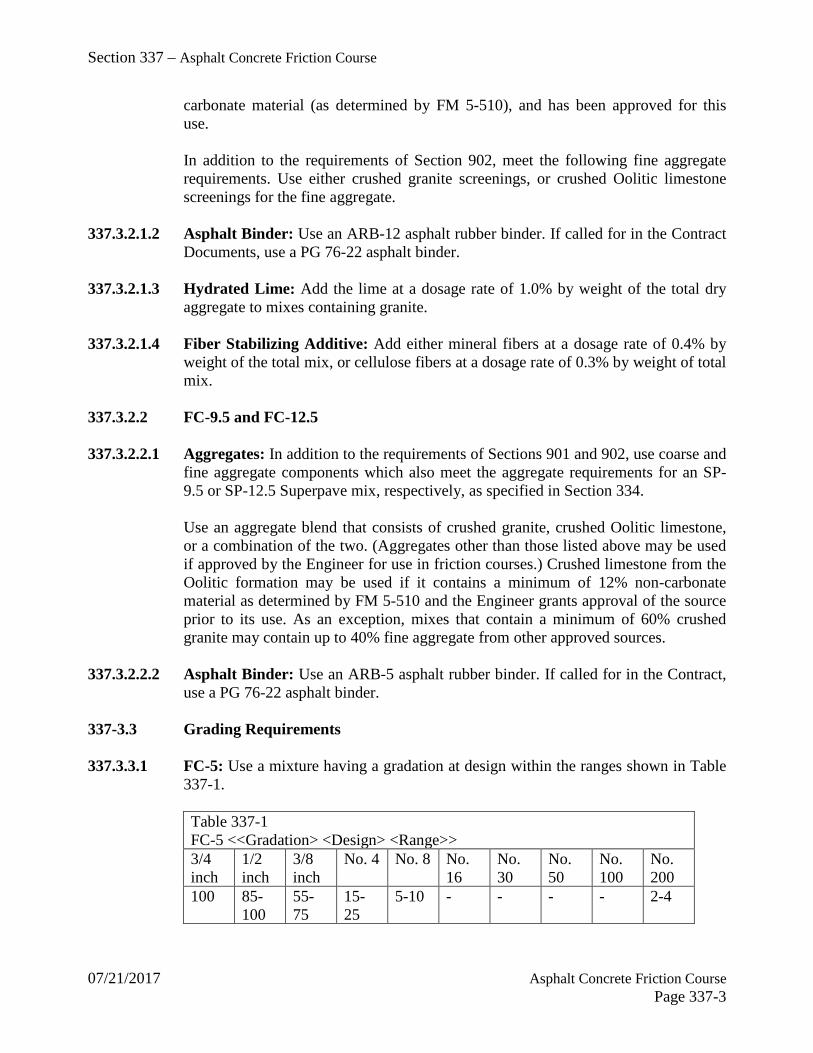
Section 337 – Asphalt Concrete Friction Course
07/21/2017 Asphalt Concrete Friction Course Page 337-3
carbonate material (as determined by FM 5-510), and has been approved for this use.
In addition to the requirements of Section 902, meet the following fine aggregate requirements. Use either crushed granite screenings, or crushed Oolitic limestone screenings for the fine aggregate.
337.3.2.1.2 Asphalt Binder: Use an ARB-12 asphalt rubber binder. If called for in the Contract
Documents, use a PG 76-22 asphalt binder. 337.3.2.1.3 Hydrated Lime: Add the lime at a dosage rate of 1.0% by weight of the total dry
aggregate to mixes containing granite. 337.3.2.1.4 Fiber Stabilizing Additive: Add either mineral fibers at a dosage rate of 0.4% by
weight of the total mix, or cellulose fibers at a dosage rate of 0.3% by weight of total mix.
337.3.2.2 FC-9.5 and FC-12.5 337.3.2.2.1 Aggregates: In addition to the requirements of Sections 901 and 902, use coarse and
fine aggregate components which also meet the aggregate requirements for an SP-9.5 or SP-12.5 Superpave mix, respectively, as specified in Section 334.
Use an aggregate blend that consists of crushed granite, crushed Oolitic limestone, or a combination of the two. (Aggregates other than those listed above may be used if approved by the Engineer for use in friction courses.) Crushed limestone from the Oolitic formation may be used if it contains a minimum of 12% non-carbonate material as determined by FM 5-510 and the Engineer grants approval of the source prior to its use. As an exception, mixes that contain a minimum of 60% crushed granite may contain up to 40% fine aggregate from other approved sources.
337.3.2.2.2 Asphalt Binder: Use an ARB-5 asphalt rubber binder. If called for in the Contract,
use a PG 76-22 asphalt binder. 337-3.3 Grading Requirements 337.3.3.1 FC-5: Use a mixture having a gradation at design within the ranges shown in Table
337-1.
Table 337-1 FC-5 <<Gradation> <Design> <Range>> 3/4 inch
1/2 inch
3/8 inch
No. 4 No. 8 No. 16
No. 30
No. 50
No. 100
No. 200
100 85-100
55-75
15-25
5-10 - - - - 2-4

Section 337 – Asphalt Concrete Friction Course
07/21/2017 Asphalt Concrete Friction Course Page 337-4
337.3.3.2 FC-9.5: Meet the design gradation requirements for a SP-9.5 Superpave fine mix as defined in 334-3.2.
337.3.3.3 FC-12.5: Meet the design gradation requirements for a SP-12.5 Superpave fine mix
as defined in 334-3.2. 337-4 Mix Design 337-4.1 FC-5: Use an FDOT approved mix design for FC-5 mixtures.
The design binder content for FC-5 within the following ranges based on aggregate type:
Aggregate Type Binder Content Crushed Granite 5.5 - 7.0 Crushed Limestone (Oolitic) 6.5 - 8.0
337-4.2 FC-9.5 and FC-12.5: Provide a mix design conforming to the requirements of 334-
3.2 unless otherwise designated in the plans. Develop the mix design using an ARB-5 or PG 76-22 asphalt binder if called for in the Contract Documents.
337-4.3 Revision of Mix Design: For FC-5, FC-9.5 and FC-12.5, meet the requirements of
334-3.3. For FC-5, all revisions must fall within the gradation limits defined in Table 337-1.
337-5 Contractor's Process Control: Provide the necessary process control of the friction
course mix and construction in accordance with the applicable provisions of 330-2 and 334-4.
The Engineer will monitor the spread rate periodically to ensure uniform thickness. Provide quality control procedures for daily monitoring and control of spread rate variability. If the spread rate varies by more than 5% of the spread rate set by the Engineer in accordance with 337-8, immediately make all corrections necessary to bring the spread rate into the acceptable range.
337-6 Acceptance of the Mixture 337-6.1 FC-9.5 and FC-12.5: Meet the requirements of 334-5. 337-6.2 FC-5: Meet the requirements of 334-5 with the following exceptions:
1. The mixture will be accepted with respect to gradation (P-3/8, P-4, and P-8), and asphalt binder content (Pb) only.
2. The standard LOT size of FC-5 will be 2,000 tons, with each LOT
subdivided into four equal sublots of 500 tons each.\

Section 337 – Asphalt Concrete Friction Course
07/21/2017 Asphalt Concrete Friction Course Page 337-5
3. Initial production requirements of 334-4.2. do not apply.
4. Use table 337-2.
5. The mixture will be accepted on the roadway with respect to surface tolerance in accordance with the applicable requirements of 334-5.2.2. No density testing will be required for these mixtures.
Table 337-2 FC-5 <<Master> <Production> <Range>> Characteristic Tolerance (1) Asphalt Binder Content (%) Target ± 0.60 Passing 3/8 inch Sieve (%) Target ± 7.50 Passing No. 4 Sieve (%) Target ± 6.00 Passing No. 8 Sieve (%) Target ± 3.50 (1) Tolerances for sample size of n = 1 from the verified mix design
337.6.2.1 Disposition of Failing Materials: Any material in-place that is represented by
failing test results will be evaluated by the Engineer to determine if removal and replacement is necessary. Remove and replace any in-place material, if required, at no cost to the county.
337-7 Special Construction Requirements 337-7.1 Hot Storage of FC-5 Mixtures: When using surge or storage bins in the normal
production of FC-5, do not leave the mixture in the surge or storage bin for more than one hour.
337-7.2 Longitudinal Grade Controls for Open-Graded Friction Courses: On FC-5, use
either longitudinal grade control (skid, ski or traveling stringline) or a joint matcher. 337-7.3 Temperature Requirements for FC-5 337.7.3.1 Air Temperature at Laydown: Spread the mixture only when the air temperature
(the temperature in the shade away from artificial heat) is at or above 65ºF. As an exception, place the mixture at temperatures lower than 65ºF, only when approved by the Engineer based on the CONTRACTOR's demonstrated ability to achieve a satisfactory surface texture and appearance of the finished surface. In no case shall the mixture be placed at temperatures lower than 60ºF.
337.7.3.2 Temperature of the Mix: Heat and combine the asphalt rubber binder and
aggregate in a manner to produce a mix having a temperature, when discharged from the plant, meeting the requirements of 330-6.3. Meet all requirements of 330-9.1.2 at the roadway. The target mixing temperature shall be established at 320ºF.
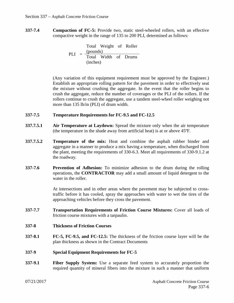
Section 337 – Asphalt Concrete Friction Course
07/21/2017 Asphalt Concrete Friction Course Page 337-6
337-7.4 Compaction of FC-5: Provide two, static steel-wheeled rollers, with an effective compactive weight in the range of 135 to 200 PLI, determined as follows:
PLI =
Total Weight of Roller (pounds) Total Width of Drums (inches)
(Any variation of this equipment requirement must be approved by the Engineer.) Establish an appropriate rolling pattern for the pavement in order to effectively seat the mixture without crushing the aggregate. In the event that the roller begins to crush the aggregate, reduce the number of coverages or the PLI of the rollers. If the rollers continue to crush the aggregate, use a tandem steel-wheel roller weighing not more than 135 lb/in (PLI) of drum width.
337-7.5 Temperature Requirements for FC-9.5 and FC-12.5 337.7.5.1 Air Temperature at Laydown: Spread the mixture only when the air temperature
(the temperature in the shade away from artificial heat) is at or above 45ºF. 337.7.5.2 Temperature of the mix: Heat and combine the asphalt rubber binder and
aggregate in a manner to produce a mix having a temperature, when discharged from the plant, meeting the requirements of 330-6.3. Meet all requirements of 330-9.1.2 at the roadway.
337-7.6 Prevention of Adhesion: To minimize adhesion to the drum during the rolling
operations, the CONTRACTOR may add a small amount of liquid detergent to the water in the roller.
At intersections and in other areas where the pavement may be subjected to cross-traffic before it has cooled, spray the approaches with water to wet the tires of the approaching vehicles before they cross the pavement.
337-7.7 Transportation Requirements of Friction Course Mixtures: Cover all loads of
friction course mixtures with a tarpaulin. 337-8 Thickness of Friction Courses 337-8.1 FC-5, FC-9.5, and FC-12.5: The thickness of the friction course layer will be the
plan thickness as shown in the Contract Documents 337-9 Special Equipment Requirements for FC-5 337-9.1 Fiber Supply System: Use a separate feed system to accurately proportion the
required quantity of mineral fibers into the mixture in such a manner that uniform

Section 337 – Asphalt Concrete Friction Course
07/21/2017 Asphalt Concrete Friction Course Page 337-7
distribution is obtained. Interlock the proportioning device with the aggregate feed or weigh system to maintain the correct proportions for all rates of production and batch sizes. Control the proportion of fibers to within plus or minus 10% of the amount of fibers required. Provide flow indicators or sensing devices for the fiber system, interlocked with plant controls so that the mixture production will be interrupted if introduction of the fiber fails.
When a batch plant is used, add the fiber to the aggregate in the weigh hopper or as approved and directed by the Engineer. Increase the batch dry mixing time by 8 to 12 seconds, or as directed by the Engineer, from the time the aggregate is completely emptied into the pugmill. Ensure that the fibers are uniformly distributed prior to the addition of asphalt rubber into the pugmill.
When a drum-mix plant is used, add and uniformly disperse the fiber with the aggregate prior to the addition of the asphalt rubber. Add the fiber in such a manner that it will not become entrained in the exhaust system of the drier or plant.
337-9.2 Hydrated Lime Supply System: For FC-5 mixes containing granite, use a separate
feed system to accurately proportion the required quantity of hydrated lime into the mixture in such a manner that uniform coating of the aggregate is obtained prior to the addition of the asphalt rubber. Add the hydrated lime in such a manner that it will not become entrained in the exhaust system of the drier or plant. Interlock the proportioning device with the aggregate feed or weigh system to maintain the correct proportions for all rates of production and batch sizes and to ensure that all mixture produced is properly treated with hydrated lime. Control the proportion of hydrated lime to within plus or minus 10% of the amount of hydrated lime required. Provide and interlock flow indicators or sensing devices for the hydrated lime system with plant controls so that the mixture production will be interrupted if introduction of the hydrated lime fails. The addition of the hydrated lime to the aggregate may be accomplished by Method (A) or (B) as follows:
337.9.2.1 Method (A) - Dry Form: Add hydrated lime in a dry form to the mixture according
to the type of asphalt plant being used.
When a batch plant is used, add the hydrated lime to the aggregate in the weigh hopper or as approved and directed by the Engineer. Increase the batch dry mixing time by eight to twelve seconds, or as directed by the Engineer, from the time the aggregate is completely emptied into the pugmill. Uniformly distribute the hydrated lime prior to the addition of asphalt rubber into the pugmill.
When a drum-mix plant is used, add and uniformly disperse the hydrated lime to the aggregate prior to the addition of the asphalt rubber. Add the hydrated lime in such a manner that it will not become entrained in the exhaust system of the drier or plant.
337.9.2.2 Method (B) - Hydrated Lime/Water Slurry: Add the required quantity of
hydrated lime (based on dry weight) in a hydrated lime/water slurry form to the

Section 337 – Asphalt Concrete Friction Course
07/21/2017 Asphalt Concrete Friction Course Page 337-8
aggregate. Provide a solution consisting of hydrated lime and water in concentrations as directed by the Engineer. Use a plant equipped to blend and maintain the hydrated lime in suspension and to mix it with the aggregates uniformly in the proportions specified.
337-9.3 Hydrated Lime Pretreatment: For FC-5 mixes containing granite, as an alternative
to 337-9.2, pretreat the aggregate with hydrated lime prior to incorporating the aggregate into the mixture. Use a feed system to accurately proportion the aggregate and required quantity of hydrated lime, and mix them in such a manner that uniform coating of the aggregate is obtained. Control the proportion of hydrated lime to within ± 10% of the amount required. Aggregate pretreated with hydrated lime in this manner shall be incorporated into the asphalt mixture within 45 days of pretreatment.
337.9.3.1 Hydrated Lime Pretreatment Methods: Pretreat the aggregate using one of the
following two methods:
Pretreatment Method A - Dry Form: Add the required quantity of hydrated lime in a dry form to the aggregate. Assure that the aggregate at the time of preteatment contains a minimum of 3% moisture over saturated surface dry (SSD) conditions. Utilize equipment to accurately proportion the aggregate and hydrated lime and mix them in such a manner as to provide a uniform coating.
Pretreatment Method B - Hydrated Lime/Water Slurry: Add the required quantity of hydrated lime (based on dry weight) in a hydrated lime/water slurry form to the aggregate. Provide a solution consisting of hydrated lime and water in a concentration to provide effective treatment. Use equipment to blend and maintain the hydrated lime in suspension, to accurately proportion the aggregate and hydrated lime/water slurry, and to mix them to provide a uniform coating.
337.9.3.2 Blending Quality Control Records: Maintain adequate Quality Control records for
the Engineer's review for all pretreatment activities. Include as a minimum the following information (for each batch or day's run of pretreatment): pretreatment date, aggregate certification information, certified test results for the hydrated lime, aggregate moisture content prior to blending, as-blended quantities of aggregate and hydrated lime, project number, customer name, and shipping date.
337.9.3.3 Certification: In addition to the aggregate certification, provide a certification with
each load of material delivered to the HMA plant, that the material has been pretreated in conformance with these specifications. Include also the date the material was pretreated.
337-10 Method of Measurement: For the work specified under this Section (including the
pertinent provisions of Sections 320 and 330), the quantity to be paid for will be the weight of the mixture, in tons.
Section 337 – Asphalt Concrete Friction Course
07/21/2017 Asphalt Concrete Friction Course Page 337-9
The bid price for the asphalt mix will include the cost of the asphalt binder (asphalt rubber (or polymer), asphalt cement, ground tire rubber, anti-stripping agent, blending and handling) and the tack coat application, as well as fiber stabilizing additive and hydrated lime (if required). There will be no separate payment or unit price adjustment for the asphalt binder material in the asphalt mix. The weight will be determined as provided in 320-2 (including the provisions for the automatic recordation system).
337-11 Basis of Payment 337-11.1 General: Price and payment will be full compensation for all the work specified
under this Section (including the applicable requirements of Sections 320 and 330).
For FC-9.5 and FC-12.5, a pay adjustment will be applied based upon the quality of the in-place material as determined on a LOT by LOT basis in accordance with Table 334-17.
337-11.2 Payment: Payment will be made under:
Item No. 337- 7- Asphaltic Concrete Friction Course - per ton.
- End of Section -

Section 341 – Asphalt Rubber Membrane Interlayer
07/21/2017 Asphalt Rubber Membrane Interlayer Page 341-1
341-1 Description: Construct an asphalt rubber membrane interlayer composed of a separate application of asphalt rubber binder covered with a single application of aggregate.
341-2 Materials 341-2.1 Asphalt Rubber Binder: Use ARB-20 meeting the requirements of Section 336. 341-2.2 Cover Material: Use Size No. 6 stone, slag, or gravel meeting the requirements of
Section 901. 341-3 Equipment 341-3.1 Power Broom: Provide a power broom for cleaning the existing pavement capable
of removing all loose material from the surface. 341-3.2 Spreading Equipment: Provide a self-propelled aggregate spreader that can be
adjusted to accurately apply the cover material at the specified rate and that spreads the material uniformly.
341-3.3 Rollers: Provide self-propelled, pneumatic-tired traffic type rollers equipped with at
least 7 smooth-tread, low-pressure tires, and capable of carrying a gross load of at least 8 tons. Maintain a minimum tire inflation pressure of 90 psi, or as specified by the manufacturer, such that in no two tires the air pressure varies more than 5 psi. Load the traffic roller as directed by the Engineer.
341-3.4 Mixing Equipment: Use mixing equipment for asphalt rubber binder designed for
that purpose and capable of producing and maintaining a homogeneous mixture of rubber and asphalt cement at the specified temperature.
341-3.5 Pressure Distributor: Use a pressure type distributor to apply asphalt rubber binder
capable of maintaining a homogeneous mixture of rubber and asphalt cement at the specified temperature and consistently apply the material in a uniform manner.
341-4 Contractor's Quality Control: Provide the necessary quality control of the asphalt
rubber binder and construction in accordance with the Contract requirements. If the rate of application varies by more than 5% from the rate set by the Engineer in accordance with 341-6, immediately make all corrections necessary to bring the spread rate into the acceptable range. The Engineer may take additional measurements at any time. The Engineer will randomly check the CONTRACTOR's measurement to verify the spread rate.
341-5 Preparation of Asphalt Rubber Binder: Combine the materials as rapidly as
possible for such a time and at such a temperature that the consistency of the binder approaches that of a semi-fluid material. Use the time and temperature for blending of the asphalt rubber binder as specified in Table 336-1. The Engineer will be the

Section 341 – Asphalt Rubber Membrane Interlayer
07/21/2017 Asphalt Rubber Membrane Interlayer Page 341-2
sole judge of when the material has reached application consistency and will determine if an extender oil or diluent is needed for that purpose. After reaching the proper consistency, proceed with application immediately. Never hold the mixture at temperatures over 350ºF for more than six hours after reaching that temperature.
341-6 Construction Procedure 341-6.1 Preparation of Surface: Prior to application of the asphalt rubber binder, clean the
existing pavement as specified in 300-5. 341-6.2 Application of Asphalt Rubber Binder: Apply the asphalt rubber binder only
under the following conditions:
a. The air temperature is above 50ºF and rising.
b. The pavement is absolutely dry.
c. The wind conditions are such that cooling of the asphalt rubber binder will not be so rapid as to prevent good bonding of the aggregate.
Uniformly apply the asphalt rubber binder, at the rate of 0.6 to 0.8 gal/yd2 as directed by the Engineer. Use an application rate based on the unit weight as shown in Table 336-1. For conversions to standard 60ºF, refer to 300-9.3. Determine the rate of application after each application operation. If the rate of application varies by more than 5% form the rate set by the Engineer, immediately make all correction to bring the spread rate into acceptable range.
341-6.3 Application of Cover Material: Immediately after application of the asphalt rubber
binder, uniformly spread the cover material at a rate of 0.26 and 0.33 ft3/yd2. The Engineer will set the exact rate. Determine the application rate at the beginning of each day's production, and as needed to control the operation, a minimum of twice per day. Maintain an application rate such that the pavement is covered uniformly with aggregate, and is one aggregate layer thick. For the cover material, use aggregate that is reasonably free of any adherent coatings and that does not contain excessive moisture. Immediately after the application of cover material, check the surface to ensure a uniform distribution of cover material and a smooth surface.
Do not separate the application of the asphalt rubber binder and the application of the cover material by more than 300 feet, unless approved by the Engineer.
341-6.4 Rolling: In order to ensure maximum embedment of the aggregate, cover the entire
width of the mat immediately by traffic rollers. For the first coverage, provide a minimum of three traffic rollers in order to accomplish simultaneous rolling in echelon of the entire width of the spread.
Section 341 – Asphalt Rubber Membrane Interlayer
07/21/2017 Asphalt Rubber Membrane Interlayer Page 341-3
After initial rolling, immediately correct all portions of the completed surface that the Engineer deems are defective (not properly covered by aggregates, fat spots, excessive free aggregate, etc.).
Following the first coverage, make additional coverages with traffic rollers as directed by the Engineer.
341-6.5 Traffic Control: For the normal sequence of construction operations, place the first
course of asphalt concrete overlay over the membrane prior to opening to traffic. 341-7 Unacceptable Asphalt Rubber Membrane Interlayer: If the asphalt rubber
membrane interlayer is unacceptable due to incorrect blending, application rate, or not meeting the requirements of this Section, or damaged prior to placement of the asphalt concrete layer, remove and replace it as directed by the Engineer at no additional cost to the COUNTY. Do not apply excessive amounts of asphalt rubber binder.
341-8 Placement of Asphalt Concrete Overlay: Ensure that the thickness and
temperature of the initial layer of asphalt concrete placed on top of the asphalt rubber membrane interlayer are such that the overlay bonds to the interlayer and the underlying layer without voids or excessive binder. Core the asphalt overlay as directed by the Engineer to evaluate the binder and aggregate spread rates, as well as the effectiveness of the asphalt concrete overlay in producing a well-bonded interlayer.
341-9 Method of Measurement 341-9.1 Asphalt Rubber Membrane Interlayer: The quantity to be paid for will be plan
quantity, in square yards, completed and accepted. 341-9.2 Bituminous Material (Asphalt Rubber Binder-Interlayer): The quantity will be
the volume, in gallons, determined as provided in 300-8. 341-10 Basis of Payment 341-10.1 Asphalt Rubber Membrane Interlayer: Price and payment will be full
compensation for all work specified in this Section, including furnishing cover materials, handling, spreading, rolling, bituminous material, and other incidental work necessary to complete this item.
341-10.2 Bituminous Material (Asphalt Rubber Binder-Interlayer): Payment will be
included in the price of the asphalt rubber membrane interlayer and will be full compensation for furnishing asphalt cement, ground tire rubber, blending and handling.

Section 341 – Asphalt Rubber Membrane Interlayer
07/21/2017 Asphalt Rubber Membrane Interlayer Page 341-4
341-10.3 Payment Items: Payment will be made under: Item No. 341- 70- Asphalt Rubber Membrane Interlayer - per square yard.
- End of Section -

Section 430 – Pipe Culverts
07/21/2017 Pipe Culverts Page 430-1
Utilize the complete latest version of the FDOT Specifications for Road and Bridge Construction for this section with the following exception: For rigid concrete pipe installation, the County waives the requirement for the laser profiling and measurement technology. The County reserves the right to implement this requirement if the submitted video report indicates a visibly substantial deviation in the joints or alignment of the culvert. The laser profiling and measurement technology will still be required for all other optional culvert material types.

Section 901 – Course Aggregate
07/21/2017 Course Aggregate Page 901-1
901-1 General 901-1.1 Composition: Coarse aggregate shall consist of naturally occurring materials such
as gravel, or resulting from the crushing of parent rock, to include natural rock, slags, expanded clays and shales (lightweight aggregates) and other approved inert materials with similar characteristics, having hard, strong, durable particles, conforming to the specific requirements of this Section.
Coarse aggregate for use in a hot bituminous mixture may also consist of reclaimed portland cement concrete pavement meeting the requirements of 901-5. Washing of this material will not be required if the requirements of 901-1.2 for maximum percent of material passing the No. 200 sieve can be met without washing.
Materials substantially retained on the No. 4 sieve, shall be classified as coarse aggregate.
901-1.2 Deleterious Substances: All coarse aggregates shall be reasonably free of clay
lumps, soft and friable particles, salt, alkali, organic matter, adherent coatings, and other substances not defined which may possess undesirable characteristics. The weight of deleterious substances shall not exceed the following percentages:
Coal and lignite (AASHTO T 113) ............................1.00 Soft and friable particles (AASHTO T 112) ..............2.00* Clay lumps (AASHTO T 112) ...................................2.00* Cinders and clinkers ...................................................0.50 Free shell ....................................................................1.00** Total Material passing the No. 200 sieve (FM 1-T 011) At Source ...................................................................1.75*** At Point of Use...........................................................3.75*** Organic Matter (wet)..................................................0.03 Chert (less than 2.40 specific gravity SSD) (AASHTO T-113) ......................................................3.00****
*The maximum percent by weight of soft and friable particles and clay lumps together shall not exceed 3.00.
**Aggregates to be used in asphalt concrete may contain up to 5% free shell. Free shell is defined as that portion of the coarse aggregate retained on the No. 4 sieve consisting of loose, whole, or broken shell, or the external skeletal remains of other marine life, having a ratio of the maximum length of the particle to the shell wall thickness exceeding five to one. Coral, molds, or casts of other shells, and crushed clam and oyster shell indigenous to the formation will not be considered as free shell.
***The requirement for maximum percent of material passing the No. 200 sieve for a lot or stockpile of any coarse aggregate component shall be as follows:

Section 901 – Course Aggregate
07/21/2017 Course Aggregate Page 901-2
a. For any samples obtained by the COUNTY for acceptance purposes or
assurances purposes at the source of production, the average percent of material passing the No. 200 sieve of two composite samples shall not exceed 1.75%. No individual test shall exceed 2.0%.
b. For assurance samples or acceptance samples, as designated by the
COUNTY. Obtained at the point of use, the average percent of material passing the No. 200 sieve for two composite samples shall not exceed 3.75%. No individual test shall exceed 4.0%.
****This limitation applies only to coarse aggregates in which chert appears as an impurity. It is not applicable to aggregates which are predominantly chert.
901-1.3 Physical Properties: Coarse aggregates shall meet the following physical property
requirements, except as noted herein:
Los Angeles Abrasion (FM 1-T 096) ........................maximum loss 45% Soundness (Sodium Sulfate) AASHTO T104 ..........maximum loss 12%* Flat or elongated pieces ............................................maximum 10%**
*For source approval - Aggregates exceeding soundness loss limitations will be rejected unless performance history shows that the material will not be detrimental for Portland Cement Concrete or other intended usages.
**A flat or elongated particle is defined as one having a ratio between the maximum and the minimum dimensions of a circumscribing prism exceeding five to one.
901-1.4 Gradation: Coarse aggregates shall conform to the gradation requirements of Table
1, when the stone size is specified. However, Table 1 is waived for those aggregates intended for usage in bituminous mixtures, provided the material is graded on sieves specified in production requirements contained in FDOT standards and meets uniformity and bituminous design requirements.
TABLE 1 Standard Sizes of Coarse Aggregate Amounts Finer than Each Laboratory Sieve (Square Openings), weight percent Size No. Nominal
Size Square Openings
4 inches 3 1/2 inches
3 inches 2 1/2 inches
2 inches 1 1/2 inches
1 inch
1 3 ½ to 1 ½ in.
100 90 to 100
- 25 to 60 - 0 to 15 -
2 2 ½ to 1 ½ inches
- - 100 90 to 100
35 to 70 0 to 15 -
24 2 ½ to ¾ - - 100 90 to - 25 to 60 -

Section 901 – Course Aggregate
07/21/2017 Course Aggregate Page 901-3
inches 100 3 2 to 1
inches - - - 100 90 to
100 35 to 70 0 to 15
357 2 inches to No. 4 [50 to 4.75 mm]
- - - 100 95 to 100
- 35 to 70
4 1 ½ to ¾ inches
- - - - 100 90 to 100
20 to 55
467 1 ½ inches to No. 4
- - - - 100 95 to 100
-
5 1 to ½ inches
- - - - - 100 90 to 100
56 1 to 3/8 inches
- - - - - 100 90 to 100
57 1 inch to No. 4
- - - - - 100 95 to 100
6 ¾ inch to 3/8 inch
- - - - - - 100
67 ¾ to No. 4 - - - - - - 100 68 ¾ inch to
No. 8 - - - - - -
7 ½ inch to No. 4
- - - - - - -
78 ½ inch to No. 8
- - - - - - -
8 3/8 inch to No. 8
- - - - - - -
89 3/8 inch to No. 16
- - - - - - -
9 No. 4 to No. 16
- - - - - - -
10 No. 4 to 0 - - - - - - - TABLE 1 (Continued) Standard Sizes of Coarse Aggregate Amounts Finer than Each Laboratory Sieve (Square Openings), weight percent Size No. Nominal
Size Square Openings
¾ inch ½ inch 3/8 inch No. 4 No. 8 No. 16 No. 50
1 3 ½ to 1 ½ in.
0 to 5
2 2 ½ to 1 ½ inches
0 to 5
24 2 ½ to ¾ 0 to 10 0 to 5
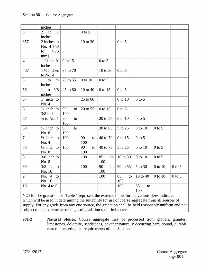
Section 901 – Course Aggregate
07/21/2017 Course Aggregate Page 901-4
inches 3 2 to 1
inches 0 to 5
357 2 inches to No. 4 [50 to 4.75 mm]
10 to 30 0 to 5
4 1 ½ to ¾ inches
0 to 15 0 to 5
467 1 ½ inches to No. 4
35 to 70 10 to 30 0 to 5
5 1 to ½ inches
20 to 55 0 to 10 0 to 5
56 1 to 3/8 inches
45 to 80 10 to 40 0 to 15 0 to 5
57 1 inch to No. 4
25 to 60 0 to 10 0 to 5
6 ¾ inch to 3/8 inch
90 to 100
20 to 55 0 to 15 0 to 5
67 ¾ to No. 4 90 to 100
20 to 55 0 to 10 0 to 5
68 ¾ inch to No. 8
90 to 100
30 to 65 5 to 25 0 to 10 0 to 5
7 ½ inch to No. 4
100 90 to 100
40 to 70 0 to 15 0 to 5
78 ½ inch to No. 8
100 90 to 100
40 to 75 5 to 25 0 to 10 0 to 5
8 3/8 inch to No. 8
100 85 to 100
10 to 30 0 to 10 0 to 5
89 3/8 inch to No. 16
100 90 to 100
20 to 55 5 to 30 0 to 10 0 to 5
9 No. 4 to No. 16
100 85 to 100
10 to 40 0 to 10 0 to 5
10 No. 4 to 0 100 85 to 100
NOTE: The gradations in Table 1 represent the extreme limits for the various sizes indicated, which will be used in determining the suitability for use of coarse aggregate from all sources of supply. For any grade from any one source, the gradation shall be held reasonably uniform and not subject to the extreme percentages of gradation specified above. 901-2 Natural Stones: Course aggregate may be processed from gravels, granites,
limestones, dolomite, sandstones, or other naturally occurring hard, sound, durable materials meeting the requirements of this Section.

Section 901 – Course Aggregate
07/21/2017 Course Aggregate Page 901-5
901-2.1 Gravels: Gravel shall be composed of naturally occurring quartz, free from deleterious coatings of any kind. The minimum dry-rodded weight AASHTO T19 shall be 95 lb/ft3.
Crushed gravel shall consist of a minimum of 85%, by weight, of the material retained on the No. 4 sieve, having at least three fractured faces.
901-2.2 Granites: Coarse aggregate produced from the crushing of granites shall be sound
and durable. For granites to be used in bituminous mixtures and surface treatments, the Los Angeles Abrasion requirement of 901-1.3 is modified to permit a maximum loss up to 50 (FM 1-T 096). Maximum amount of mica schist permitted is 5% (AASHTO T 189).
901-2.3 Limestones, Dolomite and Sandstone: Coarse aggregates may be produced from
limestone, dolomite, sandstones, and other naturally occurring hard, durable materials meeting the requirements of this Section.
Pre-Cenozoic limestones and dolomite shall not be used as crushed stone aggregates either coarse or fine for Asphalt Concrete Friction Courses, or any other asphalt concrete mixture or surface treatment serving as the final wearing course. This specifically includes materials from the Ketone Dolomite (Cambrian) Newala Limestone (Mississippian), and Northern Alabama and Georgia.
As an exception to the above up to 20% fine aggregate from these materials may be used in asphalt concrete mixtures other than Friction Courses which serve as the final wearing course.
901-2.4 Cemented Coquina Rock: For Cemented Coquina Rock to be used in bituminous
mixtures, the Los Angeles Abrasion requirement of 901-1.3 is modified to permit a maximum loss up to 50 (FM 1-T 096) provided that the amount of material finer than No. 200 generated during the Los Angeles Abrasion test is less than 18%.
901-3 Manufactured Stones 901-3.1 Slags: Coarse aggregate may be produced from molten nonmetallic by-products
consisting essentially of silicates and aluminosilicates of calcium and other bases, such as air-cooled blast-furnace slag or phosphate slag, provided it is reasonably uniform in density and quality, and reasonably free from deleterious substances as specified in 901-1.2. In addition it must meet the following specific requirements:
Sulfur content ............................................................not more than 1.5% Dry rodded weight AASHTO T19 ............................minimum 70 lb/ft3 Glassy Particles .........................................................not more than 10%
Slag shall not be used as an aggregate for portland cement concrete.

Section 901 – Course Aggregate
07/21/2017 Course Aggregate Page 901-6
For Air-Cooled Blast Furnace Slag, the Los Angeles Abrasion requirement of 901-1.3 is modified to permit a maximum loss up to 50 (FM 1-T 096) provided that the amount of material finer than No. 200 sieve generated during the Los Angeles Abrasion test is less than 18%.
901-4 Lightweight Aggregates 901-4.1 Lightweight Coarse Aggregate for Bituminous Construction: Lightweight coarse
aggregate may be produced from naturally occurring materials such as pumice, scoria and tuff or from expanded clay, shale or slate fired in a rotary kiln. It shall be reasonably uniform in quality and density, and free of deleterious substances as specified in 901-1.2, except that the term cinders and clinkers shall apply to those particles clearly foreign to the extended aggregate in question.
In addition, it must meet the following specific requirements:
Material passing the No. 200 Sieve maximum 3.00%, (FM 1-T 011) Dry loose weight (AASHTO T 19) ..............................33-55 lb/ft3* Los Angeles Abrasion (FM 1-T 096) ....................... maximum 35% Ferric Oxide (ASTM C 641) ................................ maximum 1.5 mg (Option of Engineer)
*Source shall maintain dry-loose unit weight within ±6% of Quality Control average. Point of use dry-loose unit weight shall be within ±10% of Source Quality Control average.
901-4.2 Lightweight Coarse Aggregate for Structural Concrete: The requirements of
901-4.1 are modified as follows:
Aggregates shall not be produced from pumice and scoria. Los Angeles Abrasion (FM 1-T 096, Section 12) shall be 45% maximum. Gradation shall meet the requirements of AASHTO M 195 for 3/4 inch, 1/2 inch and 3/8 inch.
901-5 Reclaimed Portland Cement Concrete: The reclaimed portland cement concrete
pavement shall be crushed and processed to provide a clean, hard, durable aggregate having a uniform gradation free from adherent coatings, steel reinforcement, vegetable matter, base material, joint fillers, or bituminous materials. The processing shall be controlled in accordance with the COUNTY's Standard Operating Procedure for Evaluation Approval and Control of Mineral Aggregate Sources.
901-6 Exceptions, Additions and Restrictions: Pertinent specification modifications,
based on material usage, will be found in other Sections of the specifications.
- End of Section -

Section 902 – Fine Aggregate
07/21/2017 Fine Aggregate Page 902-1
902-1 General 902-1.1 Composition: Fine aggregate shall consist of natural silica sand, screenings, local
materials, or subject to approval, other inert materials with similar characteristics, or combination thereof, having hard, strong, durable particles, conforming to the specific requirements of this Section.
Approval of mineral aggregate sources shall be in accordance with 6-3.3 of the FDOT specifications.
902-1.2 Deleterious Substances: All fine aggregate shall be reasonably free of lumps of
clay, soft or flaky particles, salt, alkali, organic matter, loam or other extraneous substances. The weight of deleterious substances shall not exceed the following percentages:
Shale ..........................................................1.0 Coal and lignite .........................................1.0 Cinders and clinkers ..................................0.5 Clay Lumps ...............................................1.0
902-2 Silica Sand 902-2.1 Composition: Silica sand shall be composed only of naturally occurring hard,
strong, durable, uncoated grains of quartz, reasonably graded from coarse to fine, meeting the following requirements, in percent total weight.
Sieve Size Percent Retained Percent Passing No. 4 0 to 5 95 to 100 No. 8 0 to 15 85 to 100 No. 16 3 to 35 65 to 97 No. 30 30 to 75 25 to 70 No. 50 65 to 95 5 to 35 No. 100 93 to 100 0 to 7 No. 200 Minimum 96 Maximum 4
Silica sand from any one source, having a variation in Fineness Modulus greater than 0.20 either way from the Fineness Modulus of target gradations established by the producer, may be rejected.
902-2.2 Organic Impurities: Silica sand shall be subject to the colorimetric test for organic
impurities. If the color produced is darker than the standard solution, the aggregate shall be rejected unless it can be shown by appropriate tests that the impurities causing the color are not of a type that would be detrimental to Portland Cement Concrete. Such tests shall be in accordance with AASHTO T21 and AASHTO T71. When tested for the effect of organic impurities on strength of mortar, the strength

Section 902 – Fine Aggregate
07/21/2017 Fine Aggregate Page 902-2
ratio at seven and 28 days, calculated in accordance with Section 11 of AASHTO T71, shall not be less than 95%.
902-3 Sands for Miscellaneous Uses 902-3.1 Anchor Bolts and Pipe Joints: Sand for setting anchor bolts, pipe joints or other
similar uses shall meet the quality requirements of 902-2 except that gradation requirements are waived.
902-3.2 Brick Masonry: Sand for brick masonry shall meet the quality requirements of 902-
2 except for gradation requirements. All the materials shall pass the No. 8 sieve, and be uniformly graded from coarse to fine.
902-3.3 Sand-Cement Riprap: Sand for sand-cement riprap shall meet the quality
requirements of 902-2 except for gradation requirements. The material shall meet the following gradation limits:
Sieve Size Percent Passing No. 4 Minimum 97% No. 100 Maximum 20% No. 200 Maximum 5%
902-4 Filter Material for Underdrains: Silica sand for use as filter material for Types I
through IV Underdrains shall meet the requirements of 902-2 except that the requirements of 902-1.2 and 902-2.2 shall not apply. The aggregate shall be reasonably free of organic matter and other deleterious materials. The gradation requirements of 902-2.1 shall apply except no more than 2% shall pass the No. 200 sieve.
Filter material for Type V Underdrain shall meet the above requirements except that there shall be no more than 1% of silt, clay and organic matter; that the aggregate shall have a Uniformity Coefficient of 1.5 or greater; and that 10% diameter shall be No. 70 to 35 sieve. The Uniformity Coefficient shall be determined by the ratio D60 divided by D10, where D60 and D10 refer to the particle diameter corresponding to 60 and 10% of the material which is finer by dry weight.
902-5 Screenings 902-5.1 Composition: Screenings shall be composed of hard, durable particles, either
naturally occurring, such as gravel screenings, or resulting from the crushing or processing of the parent rock, to include natural rock, slags, expanded clays or shales (lightweight aggregates), or other approved inert materials with similar characteristics.
Aggregates classified as screening shall conform to the following gradation requirements:

Section 902 – Fine Aggregate
07/21/2017 Fine Aggregate Page 902-3
Sieve Size Percent Passing 3/8 inch 100% No. 4 75 to 100%
902-5.2 Specific Requirements 902.5.2.1 Screenings from FDOT Approved Sources of Coarse Aggregate: Processed
screenings from fully Approved Sources of Coarse Aggregate are subject to gradation. Should Coarse Aggregate Source Approval status change, or unsatisfactory in-service history develop, additional control requirements may be implemented.
Screenings for use in hot bituminous mixture may consist of screenings from the processing of reclaimed portland cement concrete pavement to produce coarse aggregate.
902.5.2.2 Screenings from Other Sources: Screenings, from sources other than FDOT
Approved Sources of Coarse Aggregate, must meet the following additional general requirements:
Modified Los Angeles Abrasion: 95% statistical probability of meeting maximum loss of 23%. Specific Gravity* Absorption* Soundness* Sulfur* Phosphate* Extraneous Substances*
*Specific specification requirements based on material usage found in appropriate Bituminous or Portland Cement Sections.
Based on specific material characteristics, processing techniques and in-service history on COUNTY projects, specific source requirements may be assigned.
902.5.2.3 Screenings For Use in Portland Cement Concrete: Screenings produced from
either the Miami Oolite, Miami Ft. Thompson, or Loxahatchee Ft. Thompson Formations may be substituted for silica sand for use in concretes, except for concrete pavements, approach slabs, bridge decks and precast superstructure segments. (However, screenings will be permitted in the concrete when the bridge deck or approach slab is to be covered with an asphalt concrete surface course.)
These screenings must meet the gradation requirements of AASHTO M 6, Section 6.1, as well as the maximum percent passing the No. 200 sieve, Fineness Modulus,

Section 902 – Fine Aggregate
07/21/2017 Fine Aggregate Page 902-4
and Organic requirements of 902-2 Silica Sand. In addition, the saturated, surface dry specific gravity shall be at least 2.48.
902-6 Local Materials: Local materials shall be composed of hard, strong, durable
particles, either naturally occurring, such as natural sands, or resulting from the crushing or processing of parent rock, to include natural sand and rock, slags, expanded clays or shales (lightweight aggregate), or other approved inert materials with similar characteristics.
Aggregates classified as local material shall conform to the following gradation requirements:
Sieve Size Percent Passing 3/8 inch 100% No. 10 85 to 100% No. 200 Maximum 15%
In addition to meeting the requirements of 902-1.2, the material shall not contain excessive quantities of other deleterious substances, such as roots, cans, debris, etc. If clay size material is present, it shall not exceed 7%, as determined by AASHTO T88, and it shall be of a type which will not produce clay balls when used. The aggregate must be suitable for designated use, as determined by laboratory tests. If the deposit consists of stratified layers of varying characteristics and gradation, the producer shall employ such means as necessary to secure a uniform material.
Local materials will not be required to be produced under the requirements of 6-3.3, provided they can meet the above requirements.
902-7 Exceptions, Additions and Restrictions: Other specification modifications, based
on material usage may be found in the appropriate Sections of the specifications.
- End of Section -

Section 916 – Bituminous Materials
07/21/2017 Bituminous Materials Page 916-1
916-1 Superpave PG Asphalt Binder 916-1.1 Requirements: Superpave PG asphalt binders, identified as PG 64-22, PG 67-22,
and PG 76-22, shall meet the requirements of 916-1.2, AASHTO M-320 and the following additional requirements:
1. The mass loss AASHTO T-240 shall be a maximum of 0.5% for all grades.
2. The intermediate test temperature at 10 rad/s. for the Dynamic Shear
Rheometer test AASHTO T-315 shall be 25ºC for all grades.
3. An additional high temperature grade of PG 67 is added for which the high test temperature at 10 rad/sec for the Dynamic Shear Rheometer test AASHTO T-315 shall be 67ºC.
4. All PG asphalt binders having a high temperature designation of PG 67 or
lower shall be prepared without modification.
5. All PG asphalt binders having a high temperature designation higher than PG 67 shall be produced with a styrene-butadiene-styrene (SBS) or styrene-butadiene (SB) elastomer polymer modifier and resultant binder shall meet all requirements of this Specification; in addition the phase angle at 76ºC (AASHTO T-315) shall be less than or equal to 75 degrees.
6. The maximum viscosity AASHTO T-202 shall be 2400 poises for PG 64-22
and 3600 poises for PG 67-22. All hot mix asphalt (except hot mix asphalt containing 20% RAP or greater) shall contain Superpave PG asphalt binder grade PG 67-22 unless otherwise specified in the plans and/or Specifications for the hot mix asphalt product.
For all PG binder used in all hot mix asphalt, silicone shall be added to the PG binder at the rate of 25 cm3 of silicone mixed to each 5,000 gal. of PG binder. If a disbursing fluid is used in conjunction with the silicone the resultant mixture containing the full 25 cm3 of silicone shall be added in accordance with the manufacturer's recommendation. The blending of the silicone with the PG binder shall be done by the supplier prior to the shipment.
All PG binder and asphalt rubber binder for Friction Course mixes and for other hot mix asphalt products containing RAP shall contain 0.5% heat stable anti-strip additive by weight of PG binder unless specifications for the hot mix asphalt product requires testing by FM 1-T 283 and the test results indicate it is not required, or the mixture contains hydrated lime. Where FM 1-T 283 indicates an anti-strip additive is required, it shall be from 0.25 to 0.75%. The anti-strip additive shall meet the requirements of 916-5. The

Section 916 – Bituminous Materials
07/21/2017 Bituminous Materials Page 916-2
anti-strip additive shall be introduced into the PG binder by the supplier during loading.
Where PG binder is used in mixes containing reclaimed asphalt pavement (RAP), the requirements of 334-2.5.2 must also be met.
916-1.2 Qualified Products List: The Superpave PG asphalt binders supplied under this
Specification shall be one of the products included on the FDOT Qualified Products List. Any marked variation from the original test values for a material below the established limits or evidence of inadequate quality control or field performance of a material will be considered to be sufficient evidence that the properties of the material have changed, and the material will not be permitted for use on COUNTY Projects.
Suppliers shall not ship any PG binder that is not on the Qualified Products List.
916-1.3 Quality Control 916.1.3.1 Identification of Personnel and Supply Locations: The supplier's primary and
secondary representatives responsible for Quality Control shall be identified by name, title, address, telephone, fax and e-mail address. At least one of the representatives shall be located at the supply location. The supply locations shall be identified by name, address and telephone.
916.1.3.2 Specification Compliance and Quality Control Testing by the CONTRACTOR:
Specification Compliance Testing shall consist of complete testing of each PG binder shipped in accordance with AASHTO M-320 and 916-1.1 of these Specifications. Results of Specification Compliance Testing shall be available to the supplier within five working days of sampling. Specification Compliance Testing shall be conducted by a testing laboratory that participates at least annually in the AMRL Reference Sample Testing Program. The results from each AMRL proficiency Sample for each testing laboratory shall be forwarded by the supplier for each supply location in electronic format to the Project Manager. Acceptable performance in the AMRL proficiency Sample Testing Program shall be a minimum of 3 for each test. A rating of less than 3 shall require identification of appropriate action on the part of the supplier and be acceptable to the Project Manager.
Quality Control testing as a minimum shall consist of testing a representative sample of each PG binder shipped by the supplier in accordance with either:
(1) AASHTO T-202 Standard Test Method for Viscosity of Asphalts by
Vacuum Capillary Viscometer or
(2) AASHTO T-315 Test Method for Determining Rheological Properties of Asphalt Binder using a Dynamic Shear Rheometer (DSR).

Section 916 – Bituminous Materials
07/21/2017 Bituminous Materials Page 916-3
Results of Quality Control Testing shall be available to the supplier within five hours of sampling. The Quality Control testing and location where the test will be done shall be identified in the suppliers Quality Control Program.
916.1.3.3 Frequency of Sampling and Testing: Sampling of PG binders shall be done in
accordance with AASHTO T-40. Initial Specification Compliance test results shall be required for each PG binder grade for each new LOT of material which will be further subjected to Quality Control Testing in accordance with 916-1.3.1. A new LOT will occur when the material in a tank changes and the Specification Compliance Test may no longer be representative of the material in the tank. This may be due to an incoming bulk shipment of material, change in refinery run, the manufacture of a product, or a blend of material in a tank. Additional testing is as follows:
(1) Any PG binder shipped to a COUNTY project during any one calendar
month shall be tested at least once during that month for Specification Compliance in accordance with 916-1.3.1.
(2) When being shipped to COUNTY projects, samples shall be obtained by the
supplier and tested for Quality Control testing in accordance with 916-1.3.1. A single one quart representative sample of each PG binder shall be obtained and tested by the supplier each calendar week; for each rack blended PG binder, additional representative samples shall be obtained daily. Each Quality Control sample and additional daily rack blended samples shall be adequately identified and retained not less than eight weeks at the supply location. Any PG binder not shipped to COUNTY projects is not required to be sampled or tested.
(3) Split samples of any PG binder will be provided when requested by a
representative of the COUNTY. In this situation three representative one quart samples will be obtained by the supplier under the direction of the COUNTY. One sample will be submitted to the COUNTY representative, one will be tested by the supplier for Specification Compliance and one will be tested by the supplier for Quality Control. The method of obtaining the three representative one quart samples is to obtain a single gallon sample, which is then stirred and poured into three one quart cans. When split samples are requested by the COUNTY, the results from both parties will be made available within ten working days.
(4) For each rack blended PG binder, conduct minimum daily Process Control
Testing. 916.1.3.4 Reporting: A monthly report by the supplier containing Specification Compliance
and Quality Control Test results for each PG binder <LOT> shall be submitted by the supplier in electronic format to the Project Manager within seven days following the end of the calendar month. Test results for split samples shall also be included.

Section 916 – Bituminous Materials
07/21/2017 Bituminous Materials Page 916-4
Process Control Test results shall not be included. Copies of these monthly reports and supporting test reports shall be available at the supply location for a minimum of 3 years.
The report shall consist of the Specification compliance testing and Quality Control Testing of the following as applicable by these Specifications.
SUPERPAVE PG ASPHALT BINDER Test and Method Condition Specification
Minimum/Maximum Value
Original Binder Superpave PG Asphalt Binder Grade
Report
Qualified Product List Number
Report
Polymer Modifier Type (PG 76-22 Only) Report Spot Test, AASHTO T102
Standard with Naphtha Solvent
Negative for all grades
Solubility, AASHTO T44 In Trichlorethylene Minimum 99.0% Smoke Point, FM 5-519 COC Minimum 260° F Flash Point, AASHTO T48
COC Minimum 450° F
Rotational Viscosity, AASHTO T316
275° F Maximum 3 Pa-s
Absolute Viscosity, AASHTO T202
140° F As Required for Quality Control Testing
Dynamic Shear Rheometer, AASHTO T315
G*/sin δ, Test Temperature @ 10 rad/sec, °C Phase Angle, δ, (PG 76-22 Only)
Minimum 1.00 kPa Maximum 75 degrees
Rolling Thin Film Oven Test Residue (AASHTO T240) Rolling Thin Film Oven, AASHTO T240
Mass Loss % Maximum 0.50
Dynamic Shear Rheometer, AASHTO T315
G*/sin δ, Test Temperature @ 10 rad/sec, °C
Minimum 2.20 kPa
Pressure Aging Vessel Residue (AASHTO R-28) at 100°C Dynamic Shear Rheometer, AASHTO T315
G*/sin δ, Test Temperature @ 10 rad/sec, °25C
Maximum 5000 kPa
Creep Stiffness, AASHTO T-313
S (Stiffness), @ 60 sec. @ -12°C M-value @
Maximum 300 Mpa Minimum 0.300

Section 916 – Bituminous Materials
07/21/2017 Bituminous Materials Page 916-5
60 sec. @ -12°C Pressure Aging Vessel Residue (AASHTO R-28) at 110°C (Positive Spot Only) Dynamic Shear Rheometer, AASHTO T-315
G*/sin δ, Test Temperature @ 10 rad/sec, 25°C
Maximum 5,000 kPa
Creep Stiffness, AASHTO T-313
S (Stiffness), @ 60 sec. @ -12°C M-value, @ 60 sec. @ -12°C
Maximum 300 Mpa Minimum 0.300
916.1.3.5 Notification and Evaluation: In the event that a Specification Compliance test is
outside specification requirements shipments of that product to COUNTY projects will cease immediately and the CONTRACTOR and the Project Manager will be notified and the product retested for Specification Compliance (resampling as appropriate). Where the retest for Specification Compliance meets all requirements, shipments of that product may resume. Where off-specification material has been shipped and the retest confirms the original test, the CONTRACTOR and Project Manager will be informed of the steps taken to achieve specification compliance on the product shipped.
Where off-specification materials has been shipped, further shipment of that product to COUNTY projects shall remain suspended until the cause of the problem is evaluated and corrected by the supplier to the satisfaction of the Project Manager.
916.1.3.6 Certification and Verification: The supplier shall furnish certification on the bill of
lading for each shipment of PG binder delivered to a COUNTY project that includes: the quantity, the Superpave PG asphalt binder grade (including QPL number), PG binder LOT, a statement that the binder is in conformance with 916-1, and the quantity of silicone and anti-strip agent addition as applicable, including product designation (QPL number as applicable). Any special handling or temperature requirements shall be indicated on the certification and are solely the responsibility of the CONTRACTOR to follow.
The COUNTY may sample and test PG binder from the suppliers storage tank, the delivery vehicle, and/or CONTRACTORs storage tank to verify and determine compliance with this and other specification requirements. Where these tests identify material outside specification requirements, the Project Manager may require the supplier to cease shipment of that PG binder product. Further shipment of that PG binder product to COUNTY projects may remain suspended until the cause of the problem is evaluated and corrected by the supplier as necessary to the satisfaction of the Project Manager.
916-2 Recycling Agents

Section 916 – Bituminous Materials
07/21/2017 Bituminous Materials Page 916-6
916-2.1 Requirements: The asphalt recycling agent (RA) shall be an asphalt cement (PG asphalt binder) or an asphalt cement blended (as necessary) with a softening agent or flux oil, and shall meet the following requirements:
RECYCLING AGENTS Test Conditions Recycling Agent
Minimum/Maximum Value
Absolute Viscosity – AASHTO T202
140° F Target Viscosity ± 20%
Viscosity Ration After AASHTO T240
Visc. 140°F after RTFOT Visc. 140°F before RTFOT
Maximum 3
Smoke Point FM 5-519
COC Minimum 260°F
Flash Point AASHTO T48
COC Minimum 400°F
Solubility AASHTO T44
In Trichlorethylene Minimum 97.5%
Rack blending of recycling agents (blending from two RA tank sources) will be permitted to meet a required target viscosity value.
Silicone shall be added to the recycling agent at a rate of 25 cm3 for each 5,000 gallons of recycling agent. If a dispersing fluid is used in conjunction with the silicone, the resultant mixture containing the full 25 cm3 shall be added, in accordance with the manufacturer's recommendation. The blending of silicone mixture with the residue shall be done by the supplier prior to shipment.
The recycling agent shall contain 0.5% heat-stable anti-strip additive by weight of asphalt from an approved source. The anti-strip additive shall meet the requirements of 916-5. The anti-strip additive shall be introduced and mixed into the recycling agent at the terminal.
Where a recycling agent is used in mixes containing reclaimed asphalt pavement (RAP), the requirements of 334-2.5.2 must also be met.
916-2.2 Sampling and Reporting: Sampling of recycling agents shall be done in
accordance with AASHTO T-40. Initial Specification Compliance test results shall be required for each new LOT of material. A new LOT will occur when the material in a tank changes and the Specification Compliance Test may not be representative of the material in the tank. This may be due to an incoming bulk shipment of material, change in refinery run, the manufacture of a product, or a blend of material in a tank.

Section 916 – Bituminous Materials
07/21/2017 Bituminous Materials Page 916-7
A monthly report by the supplier containing Specification Compliance Test results for each RA LOT shall be submitted by the supplier in electronic format Project Manager within seven days following the end of the calendar month. Copies of these monthly reports and supporting test reports shall be available at the supply location for a minimum of three years.
916-2.3 Certification and Verification: The supplier shall furnish certification on the bill of
lading for each shipment of recycling agent delivered to a COUNTY project that includes: the quantity, the RA target viscosity, the RA LOT(s), a statement that the RA is in conformance with 916-2, and the quantity of silicone and anti-strip agent addition, including product designation (QPL number as applicable).
The COUNTY may sample and test recycling agents from the suppliers storage tank, the delivery vehicle, and/or CONTRACTORs storage tank to verify and determine compliance with this and other specification requirements. Where these tests identify material outside specification requirements, the Project Manager may require the supplier to cease shipment of RA binder from that RA LOT(s). Further shipment of RA binder from that RA LOT(s) to COUNTY projects may remain suspended until the cause of the problem is evaluated and corrected by the supplier as necessary to the satisfaction of the Project Manager.
916-3 Cut-Back Asphalts 916-3.1 Requirements: Rapid-curing, cut-back asphalt shall conform with the requirements
of AASHTO M 81, except that the penetration range shall be from 60-120 instead of 80-120.
For Grade RC-3000, in addition to the requirements shown in Table 1 of AASHTO M 81 the following values shall be added to the requirements for Distillation Test:
Distillate, Percentage by Volume of Total Distillate to 680°F
Grade R C-3000 Maximum
To 320°F 0 To 374°F 10 To 437°F 40
All other requirements for the distillation test (and for other properties included in the table) shall be as shown in Table 1 of AASHTO M 81.
Medium-curing, cut-back asphalt shall conform with the requirements of AASTHO M 82.
916-3.2 Sampling, Certification, and Verification: Sampling of cut-back asphalts shall be
done in accordance with AASHTO T-40. For each tank of cut-back asphalt delivered to or prepared at the asphalt terminal, the asphalt supplier shall submit a

Section 916 – Bituminous Materials
07/21/2017 Bituminous Materials Page 916-8
sample to the Project Manager upon request for testing before use. A pretest number will then be assigned by the Project Manager which shall be furnished with all cut-back asphalt delivered to the project. The pretest number shall be valid for six months from the date of issue.
The COUNTY may sample and test pre-tested cut-back asphalt from the suppliers storage tank, the CONTRACTORs transport tank and/or distributor to verify and determine compliance with this and other specification requirements. Where these tests identify material outside specification requirements, the Project Manager may require the supplier to cease shipment of that pretested cut-back asphalt product. Further shipment of that pretested cut-back asphalt product to COUNTY projects may remain suspended until the cause of the problem is evaluated and corrected by the supplier as necessary to the satisfaction of the Project Manager.
916-4 Emulsified Asphalts 916-4.1 Requirements: Anionic Emulsified Asphalt shall meet the requirements of
AASHTO M 140 with the exception that the cement mix test will be waived when the asphalt is used in non-mix application, such as tack coats and primes. Cationic Emulsified Asphalt shall meet the requirements of AASHTO M 208. Additional emulsions permitted by specifications shall meet the following requirements:
HIGH FLOAT EMULSIONS Test Conditions Asphalt Emulsion
Grade AE-60 Minimum/Maximum
Tests on Emulsion: Saybolt Furol Visc 122°F 75/400 seconds Settlement 5 days (a) Maximum 5% Storage Stability 24 hours (b) Maximum 1% Sieve Test Maximum 0.10% Desmulsibility 50 mL CaC12 0.10 N Minimum 75% Residue by Distillation Minimum 65% Oil Portion 500°F Dist. Maximum 1% by volume Tests on Residue: Penetration (0.1 mm) 77ºF, 100 g, 5 seconds minimum 40 Absolute Viscosity 140ºF minimum 3,200 poise Ductility 77ºF,
50 mm/minute minimum 400 mm
Float Test 140ºF minimum 1,200 seconds Solubility in Trichlorethylene minimum 97.5% Test Conditions Asphalt Emulsion
Grade AE-90 Minimum/Maximum
Tests on Emulsion:

Section 916 – Bituminous Materials
07/21/2017 Bituminous Materials Page 916-9
Saybolt Furol Visc 122°F 75/400 seconds Settlement 5 days (a) Maximum 5% Storage Stability 24 hours (b) Maximum 1% Sieve Test Maximum 0.10% Desmulsibility 50 mL CaC12 0.10 N Minimum 75% Residue by Distillation Minimum 65% Oil Portion 500°F Dist. Maximum 2% by volume Tests on Residue: Penetration (0.1 mm) 77ºF, 100 g, 5 seconds minimum 70 Absolute Viscosity 140ºF minimum 1,600 poise Ductility 77ºF,
50 mm/minute minimum 400 mm
Float Test 140ºF minimum 1,200 seconds Solubility in Trichlorethylene minimum 97.5% Test Conditions Asphalt Emulsion
Grade AE-150 Minimum/Maximum
Tests on Emulsion: Saybolt Furol Visc 122°F 75/400 seconds Settlement 5 days (a) Maximum 5% Storage Stability 24 hours (b) Maximum 1% Sieve Test Maximum 0.10% Desmulsibility 50 mL CaC12 0.10 N Minimum 75% Residue by Distillation Minimum 65% Oil Portion 500°F Dist. Maximum 3% by volume Tests on Residue: Penetration (0.1 mm) 77ºF, 100 g, 5 seconds minimum 125 Absolute Viscosity 140ºF minimum 800 poise Ductility 77ºF,
50 mm/minute minimum 400 mm
Float Test 140ºF minimum 1,200 seconds Solubility in Trichlorethylene minimum 97.5% Test Conditions Asphalt Emulsion
Grade AE-200 Minimum/Maximum
Tests on Emulsion: Saybolt Furol Visc 122°F 75/400 seconds Settlement 5 days (a) Maximum 5% Storage Stability 24 hours (b) Maximum 1% Sieve Test Maximum 0.10% Desmulsibility 50 mL CaC12 0.10 N Minimum 75% Residue by Distillation Minimum 62% Oil Portion 500°F Dist. Maximum 8% by volume

Section 916 – Bituminous Materials
07/21/2017 Bituminous Materials Page 916-10
Tests on Residue: Penetration (0.1 mm) 77ºF, 100 g, 5 seconds minimum 150 Absolute Viscosity 140ºF minimum 400 poise Ductility 77ºF,
50 mm/minute
Float Test 140ºF minimum 1,200 seconds Solubility In Trichlorethylene minimum 97.5% (a) The test requirement for settlement may be waived when the emulsified asphalt is used in less than five days. (b) The 24-hour (one day) storage stability test may be used instead of the five day settlement test. SPECIAL MS-EMULSION Test Conditions Minimum/Maximum Tests on Emulsion: Saybolt Furol Visc 77°F Minimum 45 seconds Storage Stability 24 hours Maximum 1% Sieve Test 50 mL CaC12 0.10 N Maximum 0.10% Desmulsibility Minimum 65% Residue by Distillation Minimum 62% Naphtha Content 500°F Dist. Maximum 8% by volume Tests on Residue: Penetration (0.1 mm) 77°F, 100 g, 5 seconds Minimum 50 Ductility 77°F, 50 mm/minute Minimum 400 mm Absolute Viscosity 140°F Minimum 800 poise Solubility In Trichlorethylene Minimum 97.5% Maximum application temperature shall be 170°F EMULSIFIED ASPHALT GRADE CRS-2H Test Conditions Minimum/Maximum Tests on Emulsion: Saybolt Furol Visc. 122ºF 100/400 seconds Settlement 5 days (a) maximum 5% Storage Stability 24 hour (b) maximum 1% Demulsibility 35 mL 0.8% Sodium Dioctyl
Sulfosuccinate (c) minimum 40%
Particle Charge positive Sieve Test maximum 0.1% Residue minimum 65% Tests on Residue: Penetration (0.1 mm) 77ºF, 100 g, 5 seconds 80/140 Ductility 77ºF, 50 mm/minute minimum 400 mm Solubility in Trichloroethylene minimum 97.5% (a) The test requirement for settlement may be waived when the emulsified asphalt is used in less than five days.

Section 916 – Bituminous Materials
07/21/2017 Bituminous Materials Page 916-11
EMULSIFIED ASPHALT GRADE CRS-2H Test Conditions Minimum/Maximum (b) The 24-hour (one day) storage stability test may be used instead of the five day settlement test. (c) The demulsibility test shall be made within 30 days from date of shipment. ASPHALT EMULSION PRIME (AEP) Test Conditions Minimum/Maximum Tests on Emulsion: Saybolt Furol Visc. 77ºF 20/150 seconds Settlement 5 days (a) maximum 5% Storage Stability 24 hour (b) maximum 1% Sieve Test maximum 0.1% Residue minimum 55% Naphtha Content 500ºF. Dist maximum 12% by volume Tests on Residue: Penetration (0.1 mm) 77ºF, 100 g, 5 seconds 40/200 Ductility 77ºF, 50 mm/minute minimum 400 mm Solubility in Trichloroethylene minimum 97.5% (a) The test requirement for settlement may be waived when the emulsified asphalt is used in less than five days. (b) The 24-hour (one day) storage stability test may be used instead of the five day settlement test. ASPHALT EMULSION GRADE RS-1h Test Conditions Minimum/Maximum Tests on Emulsion: Saybolt Furol Visc 77ºF 20/100 seconds Storage Stability 24 hour maximum 1% Demulsibility 35 mL 0.02N CaCl2 (a) minimum 60% Sieve Test maximum 0.10% Residue by Distillation minimum 55% Naphtha Portion 500ºF. Dist (b) maximum 3% by volume Tests on Residue From Distillation Test: Penetration (0.1 mm) 77ºF, 100 g,
5 seconds minimum 60
Viscosity 140ºF minimum 1,600 poise Ductility 77ºF,
50 mm/minute minimum 400 mm
Solubility in Trichloroethylene minimum 97.5% (a) The demulsibility test shall be made within 30 days from the date of shipment. (b) When RS-1 has been modified to include naphtha, the 24-hour storage stability test will be waived. EMULSION PRIME (RS TYPE) Test Conditions Minimum/Maximum

Section 916 – Bituminous Materials
07/21/2017 Bituminous Materials Page 916-12
Tests on Emulsion: Saybolt Furol Visc. 77ºF minimum 75 seconds Storage Stability 24 hour maximum 1.0% Sieve Test maximum 0.1% Naphtha Content 5/15% by volume Residue minimum 55% Tests on Residue:* Penetration (0.1 mm) 77ºF, 100 g, 5 seconds minimum 50 Viscosity 140ºF minimum 800 poise Solubility in Trichloroethylene minimum 97.5% * Residue by distillation shall be in accordance with AASHTO T 59 except that the maximum temperature shall be 329 ± 10ºF [165 ± 5ºC] and the sample shall be maintained at this temperature for 20 minutes. EPR-1 PRIME (e) Tests Conditions Minimum/Maximum Tests on Emulsion: Saybolt Furol Visc. 77ºF 6/24 seconds Storage Stability 24 hour maximum 0.5% Sieve Test (a) maximum 0.1% Residue by Distillation (b) minimum 20% Particle Charge Test (c) positive Test on Residue: (d) Flash Point COC minimum 410ºF Viscosity 140ºF 600/1000 cSt (a) Distilled water shall be used in place of 2% sodium oleate solution. (b) Residue by distillation shall be in accordance with AASHTO T 59 with the exception that a 50 g sample is heated to 300ºF [149ºC] until foaming ceases, then cooling immediately and calculating results. (c) Caution: this material has a positive particle charge, and therefore should not be mixed with materials having a negative particle charge. (d) Residue by distillation shall be in accordance with AASHTO T 59 except that the maximum temperature shall be 329 ± 10ºF [165 ± 5ºC] and the sample shall be maintained at this temperature for 20 minutes. (e) EPR-1 Prime shall not be diluted and in the event that EPR-1 Prime is not used in a 12-hour period, the material shall be thoroughly mixed by circulation or other suitable means prior to it’s use. 916-4.2 Sampling, Certification, and Verification: For each tank of emulsified asphalt
delivered to or prepared at the asphalt terminal, the asphalt supplier shall submit a sample to the COUNTY representative for testing before use. A pretest number will then be assigned by the Project Manager which shall be furnished with all emulsified asphalt delivered to the project. The pretest number shall be valid for six months from the date of issue.

Section 916 – Bituminous Materials
07/21/2017 Bituminous Materials Page 916-13
The COUNTY may sample and test pretested emulsified asphalt from the suppliers storage tank, the CONTRACTORs transport tank and/or distributor to verify and determine compliance with this and other specification requirements. Where these tests identify material outside specification requirements, the Project Manager may require the supplier to cease shipment of that pretested emulsified asphalt product. Further shipment of that pretested emulsified asphalt product to COUNTY projects may remain suspended until the cause of the problem is evaluated and corrected by the supplier as necessary to the satisfaction of the Project Manager.
916-5 Liquid Anti-strip Agents 916-5.1 Requirements: Liquid anti-strip agents may be tested by the COUNTY in
accordance with FM 5-508. Tensile strength ratios will be calculated for the following two conditions and expressed as percentages: 1) conditioned mixture without anti-strip to unconditioned mixture without anti-strip and 2) conditioned mixture with anti-strip to unconditioned mixture without anti-strip. A 20% gain in tensile strength ratio for condition #2 as compared to condition #1 shall be required.
916-5.2 Qualified Products List: Liquid anti-strip agents supplied under this Specification
shall be one of the products included on the Qualified Products List (QPL) as specified in 6-1. Liquid anti-strip agents must be requalified on an annual basis.
916-5.3 Mix Design Verification: Inclusion of a liquid anti-strip agent on the QPL does not
guarantee that the anti-strip will be approved for use in an asphalt mixture. Specifications may require subsequent moisture susceptibility testing per FM 1-T 283 for the particular mix design. Results from this testing may indicate the need for a larger dosage rate of anti-strip agent (up to 0.75% maximum) or a different anti-strip agent to meet the specification requirements.
- End of Section -

Section 919 – Ground Tire Rubber For Use In Asphalt Rubber Binder
07/21/2017 Ground Tire Rubber For Use In Asphalt Rubber Binder Page 919-1
919-1 Description: This Specification governs ground tire rubber for use in asphalt rubber binders for use in a variety of paving applications.
919-2 General Requirements: The ground tire rubber shall be produced from tires by an
ambient grinding method. The entire process or a final separate grinding process shall be at or above ordinary room temperature. The rubber shall be sufficiently dry so as to be free flowing and to prevent foaming when mixed with asphalt cement. The rubber shall be substantially free from contaminants including fabric, metal, mineral, and other non-rubber substances. Up to 4% (by weight of rubber) of talc or other inert dusting agent, may be added to prevent sticking and caking of the particles.
The ground tire rubber used shall be one of the products listed on the FDOT Qualified Products List (QPL).
919-3 Physical Requirements: The physical properties of the ground tire rubber shall be
determined in accordance with FM 5-559, and shall meet the following requirements:
Specific Gravity ................................................... 1.10 ± .06 Moisture Content ......................................Maximum 0.75% Metal Contaminants ..................................Maximum 0.01%
Gradation - The gradation shall meet the limits shown in Table 919-1 for the type of rubber specified. Sieve Size % Passing Type A Type B Type C
No. 16 --- --- 100 No. 30 --- 100 70-100 No. 50 100 40-60 20-40 No. 100 50-80 --- ---
919-4 Chemical Requirements: The chemical composition of the ground tire rubber shall
be determined in accordance with ASTM D 297 and shall meet the following requirements:
Acetone Extract ............................................Maximum 25% Rubber Hydrocarbon Content .............................. 40 to 55% Ash Content .................................................Maximum 8%* Carbon Black Content .......................................... 20 to 40% Natural Rubber ..................................................... 16 to 45%
* 10% for Type A rubber
Section 919 – Ground Tire Rubber For Use In Asphalt Rubber Binder
07/21/2017 Ground Tire Rubber For Use In Asphalt Rubber Binder Page 919-2
919-5 Packaging and Identification Requirements: The ground tire rubber shall be supplied in moisture resistant packaging such as either disposable bags or other appropriate bulk containers. Each container or bag of ground tire rubber shall be labeled with the manufacturer's designation for the rubber and the specific type, maximum nominal size, weight and manufacturer's batch or LOT designation.
919-6 Certification Requirements: The manufacturer of the ground rubber shall furnish
the Engineer certified test results covering each shipment of material to each project. These reports shall indicate the results of tests required by this specification. They shall also include a certification that the material conforms with all requirements of this specification, and shall be identified by manufacturer's batch or lot number.
- End of Section -

Section 931 – Metal Accessory Materials for Concrete Pavement and Concrete Structures
07/21/2017 Metal Accessory Materials for Concrete Pavement and Concrete Structures Page 931-1
The following replaces section 931-1.1 of the FDOT Specifications: 931-1.1 Steel Bars: Unless otherwise shown in the Plans, billet steel bars for concrete
reinforcement shall conform to the requirements of ASTM A615 Grade 60 except that the process of manufacture will not be restricted. For processes not included in ASTM A615 the phosphorus content will be limited to 0.08%.
The following special requirements shall apply:
(1) Unless otherwise specified or shown in the Plans all reinforcement bars No. 3 and larger shall be deformed bars. (2) All billet-steel bars shall be of the grade called for in the Plans. (3) Twisted bars shall not be used. (4) Wherever in the Specifications the word “purchaser” appears it shall be taken to mean the Department.
Acceptance of reinforcing steel shall be based on visual inspection by the Engineer and submittal of the Manufacturer’s certified mill analysis certifying that the test results meet the specification limits of the ASTM or AASHTO designation for the particular size, grade and any additional requirements. The manufacturer’s certified mill analysis for each heat, size, and grade per shipment of reinforcing steel shall be provided to the Engineer prior to use. The Engineer will inspect samples representing each LOT of reinforcing steel. A sample is defined as the reinforcing steel and a copy of the certified mill analysis corresponding to the sample. A LOT is defined as the weight of all bars, regardless of size, grade or pay item in consecutive shipments of 80 tons or less. Samples shall be cut from bundled steel that is shipped to the jobsite.

Section 600 – Traffic Signal Overview
07/21/2017 Traffic Signal Overview 600-1
600-1 Traffic Signal Guidance: This document is the standard specification for traffic signal installation in Hillsborough County, Florida. The different sections reflect the 2010 Emost current edition of the Florida Department of Transportation Standard Specification for Road and Bridge Construction, Traffic Control Devices. Only deviations and/or clarifications will be noted. If no specific detail or clarification is provided, then the Florida Department of Transportation Standard Specification for Road and Bridge Construction is the standard to be followed.
600-2 Definitions 600-2.1 High Voltage: High voltage is defined in this document as any voltage higher than
36VAC. 600-2.1 Low Voltage: Low voltage is defined in this document as any voltage 36VAC or
lower. 600-2.1 Substantial Completion: Installation is substantially complete when there are only
minor discrepancies. These minor discrepancies will have no effect on the operation of the signal. All signals, markings, and signs will have been installed.
- End of Section -

Section 603 – General Requirements for Installation and Evaluation of Traffic Control Equipment and MaterialsTraffic Control Signals and Devices
07/21/2017 General Requirements for Traffic Control Signals and Devices 603-1
Replace the existing language of the respective paragraphs within Section 603 of the FDOT Standard Specifications for Road and Bridge Construction with the following: 603-2.2 Exceptions: The County may grant an exception to the requirements in traffic signal
equipment and materials, when in the interest of the public or the County and to provide for advantages of state of the art equipment.
603-4 Systems Approval Requirement: The Hillsborough County Traffic Engineering
Office will review and approve any system design plan of a traffic control signal device, that is controlled and/or operated from a remote location by electronic computers or similar devices. Hillsborough County’s current central Traffic Management system is the ATMS.now system. All controllers and controller cabinets along with associated equipment must be compatible and operate with the ATMS.now system.
603-5 Device Approval Process: The traffic control signal devices will have been approved by the State of Florida and the Hillsborough County Traffic Engineering Office.
The following are Hillsborough County’s additions to Section 603 of the FDOT Standard Specifications for Road and Bridge Construction: 603-3 Definitions 603-3.1 High Voltage: High voltage is defined in this document as any voltage higher than
36VAC. 603-3.2 Low Voltage: Low voltage is defined in this document as any voltage 36VAC or
lower. 603-3.3 Substantial Completion: Installation is substantially complete when there are only
minor discrepancies. These minor discrepancies will have no effect on the operation of the signal. All signals, markings, and signs will have been installed.
603-5.1 Device Approval Process: The traffic control signal devices will have been
approved by the State of Florida and the Hillsborough County Traffic Engineering Office.
- End of Section -

Section 611 – Signal Installation Acceptance Procedures for Traffic Control Signals
07/21/2017 Acceptance Procedures for Traffic Signals and Devices 611-1
The following are Hillsborough County’s additions to Section 611-2 of the FDOT Standard Specifications for Road and Bridge Construction: 611-2.4.1 Hillsborough County Inspection Procedure 611-2.4.1.1 New Signal Installations: New signals (no signal previously at intersection) will be
inspected when the signal is at substantial level of completion. All signals, pedestrian signals and signs, markings, wiring, loops, and video detection will be in place. Minor requirements such as duct seal on conduits, advance signal ahead signs, and overhead illuminated signs may still be outstanding if the reason for lack of completion is significantly justified. The electrical service release will not be sent to the power company until the signal is determined to be at substantial completion by the traffic signal inspector.
611-2.4.1.2 Updated Signal Installation: New signals, where a traffic signal previously existed
and is still operational, will be inspected when the signal is at a substantial level of completion. The electrical service release will typically be sent to the power company at substantial completion. Exceptions to this are in cases where there are documented Maintenance of Traffic (MOT) issues that require the new signal to be operational prior to a substantial completion point or there is conflicting existing signal equipment that is limiting the project’s progress. A typical issue that would allow such an early power release would be if the existing traffic signal strain poles are conflicting with new road construction and their removal is essential to completion of the road work. Release of power for the new signal may be completed if, in the opinion of the traffic signal inspector and his supervisor, it is necessary to maintain an operational traffic signal. The traffic signal inspector will perform a safety inspection to determine the new signal is installed sufficiently to allow it to operate safely.
Replace the existing language of Section 611-3 of the FDOT Standard Specifications for Road and Bridge Construction with the following: 611-3 Signal Timing: The signal timing will typically be provided by the County. In the
case of updated signal installation, the Engineer of Record will provide signal timings when any phasing changes have occurred from the old traffic signal to the new traffic signal. If no changes in phasing have occurred, the existing time sheet may be implemented at the time the signal is swapped over. In the case where a new traffic signal (no signal previously existed) is being installed in a coordinated corridor, the Engineer of Record will provide basic timings and Hillsborough County Traffic Engineering (Timings Section) will provide the coordinated timing plan.
The following are Hillsborough County’s additions to Section 611-5 of the FDOT Standard Specifications for Road and Bridge Construction: 611-5 Contractor’s Warranty Period for Signal Installations

Section 611 – Signal Installation Acceptance Procedures for Traffic Control Signals
07/21/2017 Acceptance Procedures for Traffic Signals and Devices 611-2
611-5.1 General Requirements: Follow the Florida Standard for Road and Bridge
Construction except; as clarification, the following applies: the contractor is responsible for all maintenance of the newly installed of traffic signals within the limits of the construction project from the date construction begins until all installation discrepancies (punch) list items have been corrected. The 90-day warranty period will begin at the end of the 48-hour burn-in test unless an equipment failure occurs during that 48-hour burn in period. The 48-hour burn-in test is considered the first 48-hours after this traffic signal is first placed into full operation.
611-5.2 Contractor’s Responsibilities 611-5.2.1 Responsibility for maintenance of existing traffic signal during construction:
The contractor is responsible for all maintenance of the traffic signal as soon as any modification is made to the existing traffic signal or there is a stipulation in the plan sheets or County Specifications which determine the contractor will assume maintenance responsibility at commencement of the project. The mMaintenance of the traffic signal is defined as repair and/or replacement of any equipment or hardware failures which cause the traffic signal to operate abnormally. This will include any damages caused by accident or criminal behavior to any underground or aboveground traffic signal related facility. Once the replacement signal is operational, the responsibility for maintenance of the new traffic signal will continue to be the responsibility of the contractor until all of the discrepancies or punch list items have been corrected and the traffic signal is deemed “acceptable”.
611-5.2.2 Responsibility for maintenance of a new traffic signal: The contractor is
responsible for all maintenance of the new traffic signal from the moment the construction starts until all discrepancies or punch list items have been corrected and the traffic signal is deemed “acceptable”.
611-5.2.3 Contractor’s responsibility during the warranty period: The warranty period of
90 days commences after the 48-hour burn-in of the traffic signal. This is defined as 48 hours after the new traffic signal is fully activated. If a new signal is turned on prior to all functions of the traffic signal being fully serviceable, the warranty period will begin when all functions of the traffic signal have been installed and are functional. As an example: a new traffic signal that is replacing an existing traffic signal may have to be activated due to MOT reasons prior to the pedestrian signals being functional. In this case, the 90-day warranty period will commence when the pedestrian signals, all noted discrepancies and any other item not functional have been fully activated, have been corrected, and/or are fully functional. If the maintenance responsibility of the traffic signal has been turned over to Hillsborough County during the warranty period, the contractor will be responsible for the provisions identified in Section 611-5.2 of the Florida Standard for Road and Bridge Construction.

Section 611 – Signal Installation Acceptance Procedures for Traffic Control Signals
07/21/2017 Acceptance Procedures for Traffic Signals and Devices 611-3
During any period when the contractor is responsible for maintenance of the signal, the contractor will respond to a reported traffic signal failure or operational problem within two hours. If the contractor fails to respond within the allotted period and the County responds to the failure or operational problem, the contractor is subject to back charges for the County’s expenses.
- End of Section -

Section 620 Signal Installation Grounding and Lighting Protection
07/21/2017 Grounding and Lighting Protection 620-1
The following are Hillsborough County’s additions to Section 620 of the FDOT Standard Specifications for Road and Bridge Construction: 620-3 Requirements for Grounding 620-3.1 General: Meet all local electrical codes. Install insulated green No. 4 AWG copper
wire for electrical or lightning protection ground from the system ground (electrical service ground rod) to all elements of the traffic signal (pedestrian poles, mast arms, steel pull box lids, etc). No. 4 AWG insulated green copper wire will be used from the electrical service disconnect to the traffic signal controller ground. The main ground wire from the meter panel to the ground rod will be #4 AWG solid copper wire. All connections to ground rods and connections where multiple ground wires intersect will be exothermically welded. Connections in the meter can, electrical service disconnect, pedestrian poles, mast arms, traffic signal controller cabinet, etc will be made with a crimped lug that is bolted to a grounding point or direct connection to a ground buss (usually found in the electrical service disconnect and controller cabinet). All separately grounded elements at an intersection will be bonded together (exothermically) to form an intersection grounding network and all will be tied back to the primary ground on the electrical service meter panel. The intersecting point for all ground wires in the grounding network will be a pull box adjacent to the electric service meter panel. Refer to the Typical 240/120 VAC Service drawing in the construction plans. A pull box adjacent to the electrical service meter/disconnect pole will be installed to provide an intersecting point for all the grounding network grounds. The ground wires from all ground network components (ie, signal poles, pedestrian poles, pull boxes, etc) will be brought into this one pull box to be tied to the main ground from the electrical service ground. All connection points between ground wires and ground rods and all connection points where multiple ground wires meet will be exothermically welded. The measured value of the grounding array at any point will be 10Ω or less. If that value can not be achieved with the specified number of ground rods, additional ground rods will be installed at no cost to the County. Refer to the Hillsborough County Typical 240/120 VAC Service drawing in the construction plans for further guidance on grounding and surge protection device.
- End of Section -

Section 630 Conduit
07/21/2017 Conduit 630-1
Replace the existing language of the last sentence of the second paragraph wWithin Section 630-3.1 of the FDOT Standard Specifications for Road and Bridge, add the following sentence directly after paragraph eight of 630.1.1 with the following: 630-3.1 General: No The use of corrugated flexible conduits will not be allowed without the
pre-approval of the County. The following is Hillsborough County’s addition to Section 630-3.1 of the FDOT Standard Specifications for Road and Bridge Construction:
All PVC conduits will have bell ends installed prior to pulling any cable to protect the cable insulation from damage. If the installed bell ends appear to be cut and installed after the fact, all the cable will have to be pulled out of the conduit by the contractor and inspected by the County for damage. The contractor will have to reinstall undamaged or new cable at no expense to the County.
Replace the existing language of theAdd the following paragraph to the ninth eighth paragraph within Section 630-3.1 of the FDOT Standard Specifications for Road and Bridge Construction with the following:
When transitioning from metal conduit above ground to underground PVC conduit, the transition will be with a threaded female adapter. A slip type fitting will not be acceptable on the metal conduit.
Replace the existing language of the tenth paragraph within Section 630-3.1 of the FDOT Standard Specifications for Road and Bridge Construction with the following:
Install 1250 lb mule tape or equivalent the full length of all empty conduits that are designated for future use. There must be at least 36 inches of mule tape at each conduit termination point. The mule tape must be tied to a permanent object to avoid the mule tape from being inadvertently pulled out of the conduit. If all conduits in a run of conduits are empty, a continuous run of No. 14 AWG copper wire as stipulated in the FDOT design specifications will also be installed in one of the empty conduits to allow those conduits to be marked for the Florida Sunshine State Call One system. One conduit in any conduit run must have some sort of copper wire or detectable locating tape to allow for utility locating. Locating wire will not be spliced inside any conduit. Any splice that is performed with the locating wire will be spliced in the pull box.
The following is Hillsborough County’s addition to Section 630-3.2 of the FDOT Standard Specifications for Road and Bridge Construction: 630-3.2 Conduit Sizes and Quantities: All pedestrian signal bases will have two (2) each
2” PVC conduits (one (1) each high voltage and one (1) each low voltage) along with one (1) each 1” PVC conduit (ground) installed. The conduits will be routed to

Section 630 Conduit
07/21/2017 Conduit 630-2
the nearest associated pull box. All mast arm and steel strain pole foundations will have a minimum of 3-2” and 1-1” PVC conduits installed in the foundation. All traffic signal controller foundations will have 13-2” and 2-1” conduits installed in the controller foundations.
A greater than forty per cent fill of any conduit will not be allowed. The Engineer of Record will show additional conduit runs if the less than forty per cent fill can not be achieved.
The following is Hillsborough County’s addition to Section 630-3.5 of the FDOT Standard Specifications for Road and Bridge Construction: 630-5 Conduit Terminations: All PVC conduits will have bell ends installed at the
terminating ends prior to any cables being pulled into the conduits.
- End of Section -
Section 632 Signal and Interconnect Cable
07/21/2017 Signal and Interconnect Cable 632-1
The following are Hillsborough County’s additions to Section 632 of the FDOT Standard Specifications for Road and Bridge Construction: 632-3 Installation Requirements 632-3.1 Number of Conductors: The contractor will determine the number of conductors
required for each signal and interconnect cable by utilizing the Contract Documents or contacting the County traffic signal inspector. For span wire installations using trunk cables, there will be a minimum of three spare conductors for each signal trunk cable used at all signal installations. Install the three spare conductors from the controller cabinet through each signal head disconnect hanger to the furthermost disconnect hanger. Each direction or approach will have its own neutral. Double (2-way) signal heads will not be allowed as this would cause two separate directions to share one neutral. The white conductor in the signal cable will be used for the neutral. For span wire installation using individual cables to each signal head, there will be a minimum of two spare conductors to each signal head (except for potential future 5-section locations). Where the potential exists for a future 5-section, a minimum of three spare conductors will be made available. For mast arm installations, there will be two spare conductors to each signal head. Each signal head will have an individual cable from the mast arm hand hole to the signal head without any splices or breaks. All mast arms will have a hand hole terminal compartment provided by the manufacture unless specifically deleted by the Engineer of Record. If equipped with a terminal block, a trunk cable will be run to the hand hole continuously from the controller cabinet with at least three spare conductors. If no hand hole exists in the mast arm, each signal head will have a continuous signal cable from the signal head to the controller cabinet with no splices. For box span wire installations with single point attachment or where a pole mounted junction box is stipulated, a trunk cable will be run continuously from the controller cabinet to the junction box. Individual cables will be run from the junction box to the individual signal heads. Each direction will have a separate junction box. The number of spares will be the same as previously stipulated for mast arm installations. For pedestrian signals, there will be two spare conductors for all pedestrian signals. Pedestrian poles with a single pedestrian signal will have a minimum of a 5-conductor signal cable. Pedestrian poles with a double (2-way) pedestrian signal will have a minimum of a 9-conductor cable. Double (2-way) pedestrian signals will only be installed with the approval of Traffic Engineering to ensure compliance with ADA requirements. The cables for the pedestrian signals will be a continuous run from the pedestrian signal to the controller cabinet with no splices. All pedestrian buttons will have a separate 2-conductor cable (belden) run from the button to the

Section 632 Signal and Interconnect Cable
07/21/2017 Signal and Interconnect Cable 632-2
controller cabinet with no splices. The bare wire for the belden will be tied to ground in the controller cabinet. All spare signal cable conductors will be terminated on the ground bus in the controller cabinet. The spares in a signal disconnect will be terminated on the terminal strip inside the disconnect. Any other spares (mast arm, signal heads, pedestrian heads) will be individually capped or taped. All spares routed from the overhead mast arm signals to the hand hole (terminal compartment) or span wire with junction boxes will be grounded in the hand hole (terminal compartment). All spare signal cable conductors in the controller cabinet will be labeled as spare and of sufficient length to be utilized for future use anywhere in the controller cabinet. Spare signal cable conductors within the controller cabinet will be terminated to the ground buss.
632-3.3 2 Protection of Cable: Bell ends must be installed on all conduit ends prior to pulling cable in PVC conduit. Rigid conduit will have a grounding bushing (if appropriate) or a PVC bushing on the rigid conduit end. Grommets must be installed on all metal poles where cable passes through a drilled or manufactured hole unless the opening has been manufactured in such a manner that cable will not be damaged by pulling it through the opening or by laying on the opening.
632-3.4 3 Cabling for a Mast Arm Assembly or Box Span Wire Installations using Junction Boxes: If the mast arm has a terminal compartment, sufficient trunk cable conductors will be pulled from the controller cabinet to the mast arm terminal compartment to provide for cabling of the signals. The trunk cables will be terminated on a terminal strip mounted in the terminal compartment. The terminal strip will be manufactured with non-corrosive screws. The terminal compartment size will be as specified in the FDOT index or stipulated on the signalization General Note sheet. Individual signal cables will be run from each individual signal head and terminated on the terminal strip in the terminal compartment. The terminal strip will be sized to ensure that no more than three fork terminals will be installed on any one terminal position of the terminal strip. Spare conductors from each signal head will be tied to ground in the mast arm pole at the terminal compartment. If the mast arm is not equipped with a terminal compartment, individual, continuous cables will be run from the each individual signal head to the controller cabinet. In cases of box span wire installations using junction boxes mounted on the signal poles, the above guidance is applicable. In a box span application, the junction box replaces the terminal compartment.
The signal cable for each signal attached to the mast arm will protrude from the bottom of the mast arm through a grommeted hole. The cable will be formed into a drip loop and then enter the signal through the lower arm of the mast arm astro-brac assembly. The drip loop will be held in place by the use of UV rated cable ties having a minimum width of 3/8”. This can be seen belowAn example is shown in the following photo:

Section 632 Signal and Interconnect Cable
07/21/2017 Signal and Interconnect Cable 632-3
The color code will be obtained from Hillsborough County Traffic Operations prior to wiring the mast arm signals and controller cabinet.
632-3.43.1 Cabling for a Single Point Box Span or on Span Wire Installations Stipulated to have Junction Boxes: The cables running across a span wire installation will be lashed to the messenger wire using appropriate sized lashing rods. Cable ties will be used only in the area of the drip loops. NEMA approved water-tight enclosures (junction boxes) will be mounted on the each strain pole at each corner of the intersection near the weatherhead or span wire attachment point. An appropriate sized trunk cable will be run from the NEMA enclosure to the controller cabinet. Individual cables, with appropriate spares, will be installed between the NEMA enclosure and individual signal heads. All terminations in the NEMA enclosure will be terminated on a terminal strip in the NEMA enclosure. The terminal strip will be sized to ensure that no more than three fork terminals will be installed on any one terminal position of the terminal strip. Spare conductors from each signal head will be tied to ground in the NEMA enclosure. All entries into the NEMA enclosure will be with water-tight connectors.
632-3.6 Labeling: All cables and wires will be adequately labeled to ensure identification of their purpose. Labels will be permanent in nature.

Section 632 Signal and Interconnect Cable
07/21/2017 Signal and Interconnect Cable 632-4
632-3.7 Color Code: The basic color code for span wire installations is as follows:
Terminal # Wire Color Signal Indication Street 1 Solid Red Main Street Red Main 2 Solid Orange Main Street Yellow Main 3 Solid Green Main Street Green Main 4 Solid Blue Main St Yellow Arrow Main (5-section) 5 Red w/black stripe Minor Street Red Side 6 Orange w/black stripe Minor Street Yellow Side 7 Green w/black stripe Minor Street Green Side 8 Blue w/black stripe Main St Green Arrow Main (5-section) 9 Black Red Arrow (protected) Main/Side 10 Black w/white stripe Yellow Arrow Main/Side (protected/permissive) 11 White w/black stripe Green Arrow Main/Side (protected/permissive) 12 White common/Neutral always neutral 13 Red w/white stripe Red arrow (protected) usually spare 14 Black w/red stripe Yellow arrow (protected) usually spare 15 Green w/white stripe Green arrow (protected) usually spare 16 Blue w/white stripe always spare always spare
The above information is provided as general guidance. The contractor is required to contact the Hillsborough County Traffic Signal Shop for specific color code requirements based on individual intersections. Upon notification by the contractor, the Hillsborough County Traffic Signal Shop will provide specific color code information for the contractor’s use.
- End of Section -

Section 634 Span Wire Assembly
07/21/2017 Span Wire Assembly 634-1
The following are Hillsborough County’s additions to Section 634 of the FDOT Standard Specifications for Road and Bridge Construction: 634-43 Installation Requirements 634-3.4 Span Wire Guidance: When the signal cable continues past a disconnect, saddle,
gooseneck or similar device, the signal cable will be looped behind the signal hanger signal device with sufficient slack to ensure the cable does not rub against the hanger device assembly. A minimum of one inch of clearance will be obtained between the messenger block area or similar device and the cable running across the span. Lashing rod will be used to attach signal cable to the messenger or catenary. Cable ties will be used to dress up the drip loops at the disconnects or other terminating locations. The lashing wire will continue for one turn into the drip loop. Should work include running cable on an existing span with lashing wire, the contractor will un-lash the existing lashing rod, run the cable, and then re-lash. Multiple layers of lashing rod will not be allowed.
Insulators will be installed on the centenary cable or, for single point attachments on the main cable at any location where the centenary falls underneath a distribution or transmission electrical line. If insulators are installed and a disconnect and signal hanger fall under the insulator or in cases of single point attachments, a drop span will be installed underneath the insulator to allow for the installation of the signal hanger saddle clamp as depicted in the below picture and drawing.

Section 634 Span Wire Assembly
07/21/2017 Span Wire Assembly 634-2
All disconnect doors will face traffic. The contractor will contact the Traffic Signal Operation’s shop prior to installation if any questions may arise as to the orientation of the disconnect door. If the installation calls for single point attachment, the below pictures depicts Hillsborough County’s requirement when disconnects are installed. The below picture depicts a single point attachment with diagonal span. If the single point is a box span or, under certain conditions, a diagonal span, then individual NEMA enclosures (junction boxes) will be mounted on each strain pole and individual signal cables run from the NEMA enclosures to each signal and gooseneck signal hangers will be used instead of disconnects. For box span installation or certain diagonal spans, the disconnect shown below will be eliminated. Due to the movement of the span on a single point, the wires inside the disconnect that have been exposed by stripping off the outer insulation, will be tie wrapped together and carefully positioned so they do not rub against any metal surface.
If the single point is a box span, individual NEMA enclosures (junction boxes) will be mounted on each strain pole and individual signal cables run from the NEMA enclosures (junction box) to each signal. For box span installation and certain diagonal spans, the disconnect will be eliminated. Below is attachment criteria.
For single point Diagonal Span Installation

Section 634 Span Wire Assembly
07/21/2017 Span Wire Assembly 634-3
For Single Point Box Span Installation and certain Diagonal spans
For 2-point span wire assemblies when specified. Per December 17, 2015 FDOT Traffic Engineering & Operations Bulletin 12-15, this pivot-able hanger assembly is no longer authorized for use.

Section 634 Span Wire Assembly
07/21/2017 Span Wire Assembly 634-4
When specified by the Engineer, FDOT, or Hillsborough County Traffic Engineering, the contractor will be required to install the approved Per the December 17, 2015 FDOT Traffic Engineering & Operations Bulletin 12-15, the use of the above depicted pivotable hanger assembly (example shown above) instead of is no longer authorized and a standard 2-point hanger assembly will be installed. All applicable parts of the pivotable hanger assembly will be installed.
- End of Section -

Section 635 Pull, Splice, and Junction Boxes
07/21/2017 Pull and Junction Boxes 635-1
The following are Hillsborough County’s additions to Section 635 of the FDOT Standard Specifications for Road and Bridge Construction: 635-2 Materials: All pull box lids or pull box bodies will be provided with electronic
markers. The electronic markers will either be encased in the pull box cover or the marker will be a drop in device that will be inside the actual pull box enclosure. The markers will be the standard telephone marker (orange) (101.4Khz) for any communication or fiber optic pull boxes or the standard power marker (red) (169.8Khz) for any traffic signal or street light application outside of the communication and fiber optic application.
635-3 Pull Box Installation: Pull boxes will be installed with the greatest length of the
pull box perpendicular to the roadway. 635-58 General Requirements: Loops, pedestrian button, some video detection, and
Opticom (pre-emption) (low voltage) cables will be routed through the same low voltage pull box. No signal cable or interconnect cable will be routed through a low voltage pull box. Depending on the manufacturer of video detection, the video detection cables may or may not have voltages lower than 36VAC. The contractor will have to confirm with the video detection manufacturer as to what voltage is present prior to installing cable to ensure cable is placed in the appropriate pull box. Signal cables, illuminated sign cables, pedestrian cables, some video detection cables, and any other cabling with voltages over 36VAC (high voltage) will be routed through the same high voltage pull box. No low voltage or interconnect cables will be routed through the high voltage pull box. Interconnect cable cables (copper and fiber) will be routed through the same pull box. No low voltage or high voltage cables will be routed through the interconnect pull box. In cases where pull boxes and conduits are being re-used (signal update) versus an entirely new traffic signal installation, exceptions will may be made to the requirement to separate low voltage, high voltage, and interconnect cables. Exceptions will be requested by the contractor prior to starting the installation.
The following is Hillsborough County’s replacement for the second paragraph of Section 635-2.2.3 of the FDOT Standard Specifications for Road and Bridge Construction:
635-2.2.3 Dimensions: For signalized intersections, provide pull boxes with nominal cover
dimensions of 17 inches wide by 30 inches long or larger and no less than 18 inches deep unless otherwise specifically indicated on the plans. For lighting applications, provide pull boxes with nominal cover dimensions of 13 inches wide by 24 inches long or larger and no less than 12 inches deep.
- End of Section -

Section 639 Electrical Power Service AssemblyAssemblies
07/21/2017 Electrical Power Service AssemblyAssemblies 639-1
The following are Hillsborough County’s additions to Section 639 of the FDOT Standard Specifications for Road and Bridge Construction: 639-4 Installation Requirements 639-4.1 General: Hillsborough County Traffic Operations will provide obtain the electrical
service address from the County’s 911 Streets and Address’ office.. All traffic signals’ addresses will end inwith “1/8” per Tampa Electric Company’s (TECO) direction. All other electrical services (cameras, DMS, lighting load centers, etc) will not have a fraction after the address. The traffic signal subcontractor installing the electrical power service assembly will be required to obtain a layout number from Tampa Electric CompanyTECO prior to installation of the electrical power service. Once the layout number is obtained the traffic signal subcontractor will arrange to meet the assigned Tampa ElectricTECO field engineer on sight to confirm exact location and type of feed (overhead or underground). If the location of the electrical service is required to be changed by TECO, the traffic signal contractor will immediately advise Hillsborough County Traffic Operations so a new, corrected address can be obtained from the County’s 911 Streets and Address’ office. The contractor will be responsible for any additional costs associated with the installation of the electrical power service.
639-4.5 Meter Base: The meter will be securely fastened to the pole. The service meter/disconnect will not be mounted on the traffic controller cabinet. The meter will be mounted on the nearest traffic signal concrete strain pole, nearest mast arm pole, or separate (specific for electric service) concrete pole. The height of the meter will be based on the requirements of the power company (TECO). The meter will be a bypass type meter that is rated between 100 and 200 amps and approved by the electrical power company. The meter will have the address of the electrical service attached as directed by the electrical power company. The pole, meter, and disconnect will be installed within 15 feet of the point of service. If that point of service is in excess of 50 feet from the controller cabinet, a separate pole and electrical disconnect will be mounted within 15 feet of the controller cabinet.
639-4.6.1 Service Disconnect: The surge suppressor mounted on the main service disconnect
will have a rating of 150 KVa or greater per phase/leg.
- End of Section -
Section 650 Vehicular Traffic Signal Assembly
07/21/2017 Vehicular Traffic Signal Assembly 650-1
The following are Hillsborough County’s additions to Section 650 of the FDOT Standard Specifications for Road and Bridge Construction: 650-3 Installation 650-3.4 Aiming of Signal Indication: The signal will be oriented to obtain the best possible
view by the driver in the lane or lanes associated with the particular signal. If, in the opinion of the Hillsborough County inspector, the signal is not aimed correctly, the signal contractor will re-aim the signal at no additional cost to the County.
650-3.5 Wiring Connections: Each approach will have its own neutral.
For mast arm installations, each signal will have its own signal cable which will terminate in the mast arm hand hole (if so equipped) on a stainless steel equipped terminal strip. If, in the absence of a hand hole and terminal strip, each signal’s cable will be continuous from the traffic signal to the controller cabinet. In cases where there is a terminal strip in the hand hole, the trunk cable will be of sufficient size to allow for at least three spare wires available in the hand hole terminal strip. For span wire installations with disconnects, each direction will have a separate cable (four cables for a cross intersection and three cables for a T-intersection). There will be no double signal head configurations. Each direction will have a minimum of a 12-conductor cable terminated in the disconnects. For this installation, there will be a minimum of 5 spare wires in each cable. The signal cable will be terminated on the bottom portion of the terminal strip inside the disconnect. The signal will be hard-wired to the top portion of the terminal strip inside the disconnect. For span wire installations utilizing single point attachment with gooseneck devices, each direction will have its own cable. Double gooseneck devices will be used when two cables are entering an individual signal head. All unused spare conductors will be spliced through each head. The outer insulation or sheaving will not be stripped back until the cable has entered the signal head.
- End of Section -

Section 652 24/7 Solar Flashing Beacon Assembly
07/21/2017 24/7 Solar Flashing Beacon Assembly 652-1
The following Section 652 is a Hillsborough County supplement to the FDOT Standard Specifications for Road and Bridge Construction. There is not current a Section 562 for FDOT: 652-1 Description: Install 24/7 solar flashing beacon assembly. 652-2 Materials: The 24/7 flasher assembly will be on the FDOT APL list. It will be
furnished with the necessary mounting hardware to mount on a 4-1/2” OD aluminum pole. The 24/7 flasher may be a single head design or a dual head design (wig/wag). The 24/7 solar flashing beaconflasher will be designed to operate for extended periods of time with minimal sunlight. Hillsborough County Traffic Engineering or Engineer of Record will determine whether the single head or dual head design is utilized.
652-3 Installation: The 24/7 flasher will be mounted on a 4-1/2” OD aluminum pole. All
installations will require a slip type breakaway device as shown in FDOT Design Standard Index 11860 unless mounted on a concrete raised median. An alternative method using a transformer base is depicted in the FDOT Design Standard Index 11862.
652-4 Method of Measurement: Furnish and Install: The contract unit price for a 24/7 Solar Flashing Beacon Assembly will include all materials, equipment, and labor necessary to furnish and install the complete assembly.
652-5 Basis of Payment: Price and payment will be full compensation for all work specified in this Section. Payment will be made under: Pay Item Number 652 Solar Flashing Beacon Assembly – per assembly
- End of Section -

Section 653 Pedestrian Signal Assemblies
07/21/2017 Pedestrian Signal Assemblies 653-1
The following is Hillsborough County’s addition to Section 653 of the FDOT Standard Specifications for Road and Bridge Construction: 653-2 Materials: All signals will have countdown LED inserts for all signal indications. If
pedestrian signals are stipulated for post mount, the pole will be 4-1/2”(OD) spun aluminum mounted on a transformer base (T-base). The pole and T-base will be threaded.
- End of Section -

Section 654 Midblock Crosswalk Enhancement Assemblies
07/21/2017 Midblock Crosswalk Enhancement Assemblies 654-1
The following is Hillsborough County’s addition to Section 654 of the FDOT Standard Specifications for Road and Bridge Construction: 654-2 Materials. 654-2.2 Rectangular Rapid Flashing Beacon Assemblies (RRFB): The pedestrian buttons
installed on RRFB assemblies will be the piezo type button with arrow. The orientation of the mounting of the button will be such that the arrow points to the crossing.

Section 660 Inductive Loop DetectorsVehicle Detection System
07/21/2017 Inductive Loop DetectorsVehicle Detection System 660-1
The following Section 661 660 is a Hillsborough County supplement to the FDOT Standard Specifications for Road and Bridge Construction: 660-1.1 Video Description: Install video vehicle detection compatible with Hillsborough
County’s existing system including cameras, cabling, and peripheral equipment in the controller cabinet. Video detection systems used by Hillsborough County include conventional video, forward looking infrared video, and single ultra wide angle video. The contractor will contact the Hillsborough County Traffic Operations staff to determine the type of video to utilize or as identified on the signed and sealed plan sheet.
660-1.2 Microwave (radar) Description: Install microwave (radar) vehicle detection that is
compatible with Hillsborough County’s existing microwave (radar) system. The microwave (radar) system will utilize resolution bandwidth of 245MHz, have a multi-beam radar capable of covering up to 10 lanes and a radar capable of detecting presence in different lanes at a distance up to 140 feet (in curved lanes, areas with islands, and areas with medians). The contractor will contact the Hillsborough County Traffic Operations staff to determine the type of microwave (radar) to utilize or as identified on the signed and sealed plan sheet.
660-1.3 Vehicle Detection Loops: Install vehicle detection that complies with the FDOT
Design Specifications. There are three pay items that include the labor and materials to furnish and install either a Type A (660-2-101), Type B (660-2-102) or Type F (660-2-106) loop. Type A loops will be 6’ X 30’ loops placed three feet in front of the stop bar. Type B loops will be 6’ X 6’ loops placed 50’ behind the stop bar. Type F loops will be 6’ X 30’ loops placed three feet in front of the stop bar. In some instances, the Type A and Type F loops may have to be positioned further than three feet in front of the stop bar to preclude operational issues. The contractor will contact Hillsborough County Traffic Operations to confirm position prior to cutting loops.
The following Hillsborough County addition is to be inserted to the end of Section 660-2.1 of the FDOT Standard Specifications for Road and Bridge Construction: 660-2.1 Video Materials: All video or microwave (radar) vehicle detection equipment
installed in Hillsborough County will be compatible with the existing video or microwave (radar) detection equipment used by Hillsborough County unless specifically specified different by Hillsborough County Traffic Engineering.
The following Hillsborough County addition is to be inserted after the second paragraph of Section 660-3.2.2 of the FDOT Standard Specifications for Road and Bridge Construction: The following are Hillsborough County’s additions to Section 660 of the FDOT Standard Specifications for Road and Bridge Construction: 660-3 Installation Requirements

Section 660 Inductive Loop DetectorsVehicle Detection System
07/21/2017 Inductive Loop DetectorsVehicle Detection System 660-2
660-3.2.2 Saw Cuts: The loop and lead-in will be cut so that the wire will not take more than a 55° angle at any corner. In cases where new loops are being installed over the top of existing loops, an additional saw cut will be made in the existing loop at the top and bottom of the loop. This will ensure the existing loop does not interfere with the operation of the new loop that is being installed.
The following Section 660 is a Hillsborough County supplement to the FDOT Standard Specifications for Road and Bridge Construction: 660-3.2.7 This supplements Section 660-3.2.7. All loop splices will be per FDOT specification in the Design Standards 17781 except all connection at splice points will be soldered prior to installation in an appropriate enclosure. 660-3.5 Loop Position: All loops will be positioned in the center of the lane. The front
portion of the loop for stop bar loops will normally be two feet behind stop bar. Main street through loops are normally 6’X6’(Type B) loops located 50 feet behind the stop bar. If the plans call for a longer than normal loop (30’ or 40’), the front of the loop will be positioned 8’ to 10’ in front of the stop bar. Check with the Hillsborough County Signal Inspector prior to cutting the loop to ensure proper placement. If the final placement of the stop bar results in the loop position being incorrect, the signal contractor will have to re-cut the effected loop at no cost to the County.
The following Section 661 is a Hillsborough County supplement to the FDOT Standard Specifications for Road and Bridge Construction: 660-3.6 Video or Microwave (radar) Installations: Follow the specification requirements
directed by the manufacturer. All cameras will be located on the lane line between the left turn lane and thru lane except in cases where there is more than one camera per approach. If there is no left turn lane, the camera will be located in a position that centers the camera with the approaching lanes. The microwave unit will be mounted to obtain the best detection results. If necessary, the contractor will liaison with the vendor’s factory representative to determine the best mounting location. The contractor installing the video or microwave (radar) detection will liaison with the vendor’s factory representative to determine the best cable to use. The contractor will ensure the correct cable is installed from the camera or microwave (radar) to the interface panel or terminating point in the controller cabinet. The cable will be continuous from the camera or microwave (radar) to the interface panel in the controller cabinet with no splices. Connections to the video or microwave (radar) will be per the manufacturers’ instructions (directions).

Section 660 Inductive Loop DetectorsVehicle Detection System
07/21/2017 Inductive Loop DetectorsVehicle Detection System 660-3
The signal contractor will be responsible for the initial set up of the video or microwave (radar) detection. This can be achieved through the use of the contractor’s own trained employees or with a factory field technician. If the video or microwave (radar) detection was initially set up for MOT, a final video detection set up will be performed by the contactor prior to final acceptance. The video detection set up will be such that no false calls are observed and there are no dropped calls. The zones will be properly assigned to the phases they are to call. No delay will be programmed using the video programming.
Replace the existing language within Section 650-5 of the FDOT Standard Specifications for Road and Bridge Construction with the following: 660-5 Loop Assembly Identification: Identify and tag each loop assembly in the
controller or detector cabinet by lane and movement number. Use a permanent marker to write on tag or marker.
Example: EB O/S – Phase 6 EB Center – Phase 6 EB I/S - Phase 6
In the case of new signal installations, loops will be numbered L1, L2, etc starting with the first loop clockwise from the controller cabinet and continuing in a clockwise direction around the intersection. If the configuration is out of the ordinary and this technique is difficult to achieve, the contractor will contact the Hillsborough County Traffic Operations’ signal supervisor for further clarification.
The following Section 661 is a Hillsborough County supplement to the FDOT Standard Specifications for Road and Bridge Construction: 660-8.6 Video Method of Measurement 660-8.6.1 Video Furnish and Install: The contract unit price for Video Vehicle Detection,
furnished and installed will be for an entire intersection (unless specifically stipulated by Traffic Engineering), will include all necessary cameras, cables, interface units, buss interface units, power supplies and technical support.
660-8.6.2 Video Furnish: The Contract unit price for Video Vehicle Detection, furnished, will
include the cost of delivering (including shipping and handling) the required video vehicle detection equipment for an entire intersection to the specified location. The furnished items will include all specified cameras, cables, interface units, buss interface units, power supplies and technical support.

Section 660 Inductive Loop DetectorsVehicle Detection System
07/21/2017 Inductive Loop DetectorsVehicle Detection System 660-4
660-9.3 Video Basis of Payment: Price and payment will be full compensation for all work specified in this Section. Payment will be made under: Pay Item No. 660-4- Video Vehicle Detection – each or current FDOT pay item.
- End of Section -

Section 662663Emergency and Low Priority Control Preemption DetectionSignal Priority and Preemption Systems
07/21/2017 Emergency and Low Priority Control Preemption DetectionSignal Priority and Preemption Systems 662663-1
The following Section 662 663 is a Hillsborough County supplement to the FDOT Standard Specifications for Road and Bridge Construction: 662663-1 Description: Install emergency and low priority control infrared or GPS Pre-
emption detection including detectors, cabling, discriminator, discriminator rack (if required), green sensing harness (if required), GPS related equipment, and other peripheral equipment necessary to provide a complete operational emergency and low priority control infrared or GPS pre-emption system that is compatible with the existing system installed in Hillsborough County. The contractor will contact Hillsborough County to determine whether infrared or GPS installation is required.
662663-2 Materials: All emergency and low priority control infrared and GPS pre-emption detection equipment installed in Hillsborough County will be compatible with the existing pre-emption detection equipment. It will include two-cone single channel detectors for multi-lane approaches, and single-cone single channel detectors on single lane approaches, cabling, applicable GPS equipment, the applicable discriminator, a discriminator rack (as required), and a green sensing harness (as required).
662663-3 Installation: Follow the specification requirements directed by the manufacturer.
All emergency and low priority control pre-emption infrared detectors will be installed in a location on each approach to provide for optimal reception of the optical signal transmitted by the emergency vehicle. Two-cone single-channel infrared detectors will be installed on multi-lane approaches to provide optimal operation. Only factory cables are to be installed to connect the detectors to the controller cabinet. There will be no splices in any pre-emption cable. The signal contractor will be responsible for the initial set up of the emergency/low priority pre-emption detection system. This can be achieved through the use of the contractor’s own trained employees or with a factory field technician. The pre-emption detection system set up will be such that the pre-emption emitter can be received from about ¼ mile. Specific emitter programming will be set-up by Hillsborough County.
The following sentence will be inserted after the first paragraph in Section 663-5. 662663-5-4 Method of Measurement 662-4.1 Furnish and Install: The contract unit price for Emergency and Low Priority
control pre-emption detection equipment, furnished and installed, will include all necessary multi-lane and single lane detectors, factory cables, discriminator, discriminator rack (as required), GPS equipment (as required), and green sensing
Section 662663Emergency and Low Priority Control Preemption DetectionSignal Priority and Preemption Systems
07/21/2017 Emergency and Low Priority Control Preemption DetectionSignal Priority and Preemption Systems 662663-2
harness (as required) along with any other necessary equipment or hardware to complete the installation.
662-4.2 Furnish: The Contract unit price for Emergency and Low Priority control pre-
emption Detection, furnished, will include the cost of delivering (including shipping and handling) the required pre-emption vehicle detection equipment to the specified location. The furnished items will include all necessary multi-lane and single-lane detectors, factory cables, discriminator, discriminator rack (as required), GPS equipment (as required), and green sensing harness (as required) along with any other necessary equipment or hardware to complete the installation.
662-5 Basis of Payment: Price and payment will be full compensation for all work
specified in this Section. Payment will be made under:
Item No. 662-3 Emergency and Low Priority control pre-emption detection (or current FDOT pay item) – each
- End of Section -

Section 665 Pedestrian Detector Assembly
07/21/2017 Pedestrian Detector Assembly 665-1
The following are Hillsborough County’s additions to Section 665 of the FDOT Standard Specifications for Road and Bridge Construction: 665-34 Installation: The pedestrian detector wires will be individual single pair belden
wires connected to the detector and then going back to the controller cabinet without any splices through low voltage conduits. The pedestrian detector wires will not share a cable with any other device including the pedestrian signal head assembly. Install the pedestrian detector assembly at a location and mounted in a manner to meet ADA requirements and to facilitate the use of the FDOT FTP-69B-06 pedestrian sign. The FTP-69B-06 sign will be mounted above the pedestrian detector. The detector and sign will be orientated correctly to allow the sign to be used with a left or right arrow. The ADA pedestrian detector will be a non-mechanical button (piezo) with raised arrow. The detector will have to be ADA accessible compliant with a sufficient level surface where the sign and detector are located. Ensure that all detectors used are of the same manufacturer and model. Only ADA compliant detectors can be used. When an Accessible Pedestrian System (APS) is required, the APS system will be compatible with existing APS systems being utilized in Hillsborough County and the APS pushbutton assembly will have the equivalent sign as the FDOT FTP-69B-06. The APS pushbuttons will have the following features as a minimum:
- Confirmation of button push via latching LED, sound and vibrotactile bounce.
- Direction of travel voice with extended button push. - Locating tone during Don’t Walk. - Cuckoo, chirp, and voice message during walk. - Verbal countdown during pedestrian clearance. - All sounds automatically adjust to ambient noise over 60db range. - Customized walk mode sound (voice) for specific street crossing.
When mounting, place the detector housing or saddle in complete contact with the pole. Do not mount the pedestrian detector on the controller cabinet. The pedestrian detector assembly and sign will be mounted to allow for the use of the arrow shown on the pedestrian sign. When a post is required in the installation of the pedestrian detector assembly, restore the area around the post to its original condition or as required by the plans. When the an APS pedestrian pushbutton system is required, an APS Central Control Unit (CCU) will be required inside the traffic controller cabinet. The contractor will wire power for the APS CCU in the controller cabinet as specified by Hillsborough County Traffic. Do not use a 3-prong electric plug to obtain power for the APS CCU. The contractor will install and wire the APS CCU and APS push buttons per the manufacturer’s written installation specifications. The initial settings will be per factory specifications. The following setting for the buttons will be pre-set by the factory or contractor prior to acceptance:

Section 665 Pedestrian Detector Assembly
07/21/2017 Pedestrian Detector Assembly 665-2
Recommended APS Volume Settings: When setting up APS volumes it is important that they be set so that the volumes are adequately loud for the users to hear, but not so loud that they unreasonably disturb people living near the intersection or mask the traffic noise for the visually impaired pedestrian. Because ambient noise and traffic levels at intersections can vary significantly, our customers have asked us to provide recommended settings for typical intersections. In an attempt to provide this, below are shown our current default settings, along with three typical intersection types with our recommendations for settings. The description for each type is detailed below. A key factor in making volumes loud enough for users, but not disturbing to the surrounding public, is to use the extended push feature (pushing the button for 1 second or longer) to boost the volumes for a single walk cycle. The volumes can be set to play louder during the walk and clearance phase following an extended push. The settings below assume utilization of this feature.
CONFIGURATOR SETTING DEFAULT INTERSECTION TYPE DESCRIPTION SETTING A B C LOCATE VOL MIN 10% 0 0 40% LOCATE VOLUME MAX 50% 50% 65% 75% INFO MSG VOL MIN 60% 65% 70% 75% STD WALK VOL MIN 40% 30% 40% 60% STD WALK VOL MAX 70% 60% 70% 100% EXT WALK VOL MIN 60% 60% 70% 75% EXT WALK VOL MAX 80% 80% 90% 100% VOL OVER AMBIENT 0 Db 0 0 0
All settings that follow these are at the customer’s preference. If any of the above settings are close, but not quite loud enough, an option is to change the VOL OVER AMBIENT to +5 which will boost all volumes by 5 dB. You must realize that in quiet conditions the volumes will stay 5dB higher so be sure this will not be disturbing to people living near by. The +10 dB setting should only be used on “C” type intersections where you want the volumes very loud and there is no concern about disturbing the surrounding public.

Section 665 Pedestrian Detector Assembly
07/21/2017 Pedestrian Detector Assembly 665-3
Description of Intersection Types
TYPE “A” This would be a typical neighborhood intersection where ambient volumes are typically low and get very quiet at night. The traffic volume is usually fairly light and homes may be closely located to one or more corners. These settings will give the lowest possible settings in low ambient conditions. TYPE “B” This would be a typical city intersection where there are fairly high traffic volumes and moderate to occasionally high ambient conditions. Ideally, with these settings you do not want someone’s bedroom window within 15 to 20 feet of the push button station. If this is the case, the volume levels may need to be turned down below those recommended. TYPE “C” This would be a typical large intersection or high ambient noise intersection with no one living within 50-100 feet of the corner. On this type of intersection the volumes are wanted and needed to be loud. The contractor will contact Hillsborough County Traffic Division Operations (Traffic Signal) office as to any other specific settings for the APS push buttons.
- End of Section -

Section 670671 Traffic Control AssemblyControllers
07/21/2017 Traffic Control AssemblyControllers 670-1
The following are Hillsborough County’s additions to Section 670 671 of the FDOT Standard Specifications for Road and Bridge Construction: 670671-2 Materials: For Hillsborough County, use a TS2 Type 1 controller in TS2 Type 1
controller cabinet and a currently specified TS2 Type 2 controller in TS1 cabinets. Both TS2 Type 1 and TS2 Type 2 controllers will be fully capable of operating with Hillsborough County’s current central traffic management system (ATMS.now)
- End of Section -

Section 676 Controller Traffic Cabinets
07/21/2017 Controller Traffic Cabinets 676-1
Replace the existing language of Section 676-1 of the FDOT Standard Specifications for Road and Bridge Construction with the following: 676-1 Description: Install NEMA TS2 Type 1 Group IV and V Traffic Signal Controller
Cabinets. The following are Hillsborough County’s additions to Section 676 of the FDOT Standard Specifications for Road and Bridge Construction: 676-2 Materials: All Hillsborough County Traffic Controllers cabinets will conform to the
following TS2 Type 1 specifications: 676-3 Cabinet The following Hillsborough County addition is to be inserted to the end of Section 676-2.2 of the FDOT Standard Specifications for Road and Bridge Construction: 676-3.1 Cabinet Assembly: This specification sets forth the minimum requirements for a
control cabinet assembly. The cabinet assembly shall meet, as a minimum, all applicable sections of the NEMA TS2 Traffic Controller Assemblies requirements, 1998, the current version of the FDOT Minimum Specifications for Traffic Control Signal Devices (MSTCSD), and be listed on the FDOT Approved Products List (APL). The Hillsborough County controller cabinet will be provided with a standard 4-port TS2 Type 1 controller compatible with the Hillsborough County Traffic Management Center ATMS.now central operating system.
676-3.2 Cabinet Design and Construction General: The cabinet and door will be
constructed from type 5052-H32 aluminum with a minimum thickness of 0.125 inches. All welds shall be neatly formed and free of cracks, blowholes and other irregularities. The cabinet dimensions will be approximately 28” deep, 44” wide, and 56” tall. All dimensions will be + or – 2”.
All inside and outside edges of the cabinet shall be free of burrs. All sharp edges shall be made smooth.
The cabinet shall be designed and manufactured with materials that will allow for base mounting.
A rain channel shall be incorporated on all four (4) sides of the main door opening to prevent liquids from entering the enclosure. Cabinet door openings shall be double flanged outward on all four (4) sides to produce the rain channel.

Section 676 Controller Traffic Cabinets
07/21/2017 Controller Traffic Cabinets 676-2
The top of the cabinet shall incorporate a minimum of 1/2 (inch) slope toward the rear to prevent rain accumulation. The cabinet exterior shall be supplied with a natural aluminum finish. Sufficient care shall be taken in handling to ensure that scratches are minimized. All surfaces shall be cleaned of all oil residues and shall be free from weld flash.
The cabinet interior shall have a powder coated gloss white finish.
All interior seams shall be sealed with weatherproof sealant material.
All cabinets shall be supplied with a minimum of two removable shelves manufactured from 5052-H32 aluminum having a minimum thickness of 0.125 inches. Shelves shall have a minimum depth of 10.0 inches.
There will be key hole channels mounted on each interior wall or a similar mounting method. Each channel will have double rows of key holes spaced 6” apart. Each interior wall will have two channels. The key hole channels or other mounting method are provided for the purpose of mounting the cabinet components. All key hole mounting rails shall extend to within four (4) inches of the bottom and eight (8) inches of the top of the cabinet. Rivets or pop-rivets of any kind shall not be used in the cabinet or on the main panel. No bolts or screws shall protrude through the outside walls, top, bottom, or sides of the cabinet.
676-3.3 Door and Hardware: The lower section of the cabinet door shall be equipped with a louvered air entrance. The air inlet shall be large enough to allow sufficient airflow per the rated fan capacity. A removable fiberglass, high density, air filter shall be supplied with each cabinet. The filter shall be secured to the air entrance in such fashion as to maintain close contact, at all times, to the louvered air entrance. The filter retainer shall be a sufficient design to secure the filter to the door opening. The filter retainer will be manufactured to accept a filter size of 14” X 20”.
The roof of the cabinet shall incorporate an exhaust plenum with a vent screen. Perforations in the vent screen shall not exceed 0.125 inches in diameter. The cabinet will be supplied with two exhaust fans.
The main door shall be equipped with a three-point draw roller type latching mechanism or equivalent method. The push rods shall be turned edgewise at the outward supports and shall be 0.250 inch by 0.750 inch aluminum, minimum.
The handle on the main door shall include a hasp type design for the attachment of an optional padlock. The handle shall not extend beyond the perimeter of the main door at any time. The lock assembly shall be positioned so that the handle shall not cause any interference with the key when opening the cabinet door. When the door is closed and latched, the door shall automatically lock. It shall not be necessary to use a key in order to lock the door.

Section 676 Controller Traffic Cabinets
07/21/2017 Controller Traffic Cabinets 676-3
The main door shall be equipped with a mechanism to automatically hold the door open at approximately 90, 125, and 150 degrees, in windy conditions. The main door shall be equipped with a #2 tumbler lock number. The lock shall be of brass construction, and shall have a swing away cover. Two No. 2 keys shall be supplied and attached to each cabinet door upon shipment.
676-4 TS-2 Cabinet Power Supply: The TS-2 cabinet power supply shall provide regulated DC power, unregulated AC power and a line frequency reference for the TS-2 detector rack, Bus Interface Units, load switches, and other auxiliary equipment. As a minimum, the power supply shall meet all applicable requirements of the NEMA TS2 Traffic Controller Assemblies with NTCIP Requirements, 1998. In addition the 12 volt DC output shall be rated at a minimum of 5 amps.
676-5 Police Switch Compartment: A switch compartment shall be provided on the main door.
The police door lock shall be of brass construction, and shall have a swing away cover. All cabinets shall have a police panel door that utilizes a slam shut type latching mechanism. One police key shall be supplied and attached to each cabinet door upon shipment.
676-6 Panels 676-6.1 Type 1 Terminals and Facilities Main Panel Design: The main panel shall be
constructed from 5052-H32 aluminum of 0.090 inches minimum thickness and formed so as to minimize any flexing when plug-in components are installed. All main panels shall be hinged at the bottom to allow easy access to all wiring on the rear of the panel. There will be sufficient slack in cables terminating on the main panel to allow the hinging of the panel. The cabinet back panel conductors shall be arranged to allow the top of the panel to be tilted out through the main cabinet door.
676-6.2 Main Panel Configuration: The main panel shall be fully wired in the following configuration: sixteen load switch sockets (eight vehicle sockets, four pedestrian sockets, four overlap sockets) six flash transfer relay sockets, one flasher socket and two main panel BIU rack positions (expandable to four (4) TF BIUs). Reference designators for all load switch and flash transfer relay sockets shall be silk-screen labeled on the front and rear of the main panel or an equivalent labeling system.
All load switch sockets, flasher sockets, and flash transfer sockets shall be mounted on the main panel only.
The main panel will be designed to support the bottom of the load switches.

Section 676 Controller Traffic Cabinets
07/21/2017 Controller Traffic Cabinets 676-4
All field output circuits shall be terminated on a non-fused terminal block with a minimum rating of 20 amps. All main panels shall provide means of programming the controller phase outputs to load switch inputs with only the use of a screwdriver. It is preferred that all BIU #1 and #2 inputs and outputs will be terminated and labeled on terminal blocks for possible programming use and troubleshooting. At a minimum, all available alarms will be terminated to allow external programming.
There will be a Coord/Free Switch installed and labeled to allow the controller to be in coordination mode (in Coord position) if the controller is so programmed but to force the controller into free condition if the switch is placed in the Free position. This should be mounted on the main door panel.
Each controller cabinet will be supplied with a full complement of load switches, flash transfer relays, flashers, BIUs, and any other ancillary equipment regardless of intersection configuration.
Permanent alphanumerical color labels are preferred to identify all field input/output (I/O) terminals and all AC and DC power connections. All labels shall use standard nomenclature per the NEMA TS 2 Specification. The following are potential example labels that identify the appropriate termination points: • Logic ground terminations points:
• 24VDC termination points:
• 12VAC termination points:
• AC+ termination points:
• AC- (neutral) termination points:
• Earth Ground termination points:

Section 676 Controller Traffic Cabinets
07/21/2017 Controller Traffic Cabinets 676-5
• Signal Field Wire Terminations:
If the above color labeling is not used, the manufacturer will ensure all terminations and connections are sufficiently identified soto ensure their purpose is clear to the technician. All other wire termination points will be sufficiently labeled to clearly identify their purpose or identity relative to the cabinet drawing. All flash color selection shall be accomplished at the field terminals with the use of a screwdriver only or a plug-in jumper connector. It shall also be possible to select, through terminal connections, which of the two flasher circuits is connected to each phase. All cabinets shall be wired so that flasher circuit output #1 shall be wired for phases 1,2,5,6 and overlap A and overlap C. Flasher output circuit #2 shall be wired for phases 3,4,7,8 and overlap B and overlap D. All cabinets shall be pre-wired to flash phases 2 and 6 yellow and all other phases and overlaps red. It is preferred that all the control voltage inputs to the load switches will be routed to the front panel and terminated on a terminal block that is visible and labeled to enhance troubleshooting. Signal output terminals shall be screw type. Compression type termination shall not be acceptable. All termination screws shall accept both a Phillips or flat blade screwdriver as the example below depicts:
except AC- and earth ground buss bars which will be flat blade type screws similar to what is shown below:
.
All Controller Unit and Malfunction Management Unit cables shall be of sufficient length to allow the units to be placed at any location on the bottom shelf. The power cable for the controller will be for a TS2 Type-1 controller and will be of sufficient length to attach to the back of a TS2 Type 1 controller. An adapter cable will be provided to allow a TS1Type2 controller to be powered up off the “A” connector. Connecting cables shall be jacketed or sleeved in a braided nylon mesh. It is preferred that the MMU cable jacket or sleeve shall be red in color. The use of exposed tie-wraps or interwoven cables is unacceptable.

Section 676 Controller Traffic Cabinets
07/21/2017 Controller Traffic Cabinets 676-6
The controller cabinet will be provided with a GPS dome mounted on the top of the controller cabinet and properly sealed to prevent water intrusion. This GPS dome will be compatible with the existing Hillsborough County controller and central operating system and wired to provide a DB-9 male connector available in the cabinet to allow it to be plugged into the front of the controller. This GPS dome is utilized by the controller to ensure an accurate time of day. An SDLC Port 1 Interface panel shall be provided and shall include a minimum of eight D subminiature female 15 pin (DB 15) connectors. It shall be feasible to connect the SDLC cables from any device communicating over the Port 1 into any of these eight connectors. The panel shall be manufactured from aluminum. Cabinet configuration shall be provided with a minimum requirement plus three spares RS-85 Port 1 communication cables (SDLC) to (with plug mounted connectors) allow full capabilities of that cabinet. Each communication cable connector shall be a 15-pin metal shell D sub-miniature type. The cable shall be a shielded cable suitable for RS-485 communications. All main panels shall be pre-wired for a Type-16 Malfunction Management Unit capable of flashing yellow arrow (FYA) operation using NEMA Configuration G and H as identified in the NEMA Amendment 4-2012 for the Flashing Yellow Arrow (FYA).
All wiring shall be neat in appearance. All cabinet wiring shall be continuous from its point of origin to its termination point. Butt type connections/splices are not acceptable. All cabinet back panel conductors shall be soldered at its destination point as specified. Printed circuit boards, except for BIU rack and detector rack should not be used on main panels. The front door of the cabinet shall be equipped with a switch for providing cabinet door open status. The switches shall be normally closed type. The switches shall be wired to place an input to Alarm 1 (TF BIU # 2 pin 23B) as defined by the NEMA TS 2 specifications. The alarm shall be activated if the cabinet door has been opened. All connecting cables and wire runs shall be secured by mechanical clamps. Stick-on type clamps are not acceptable. A pedestrian button isolation unit (PIU) will be installed in the controller cabinet. The PIU panel/circuit card shall be installed in each cabinet. The PIU circuit card will be a removable to allow for easy replacement of that circuit card in case of failure. The PIU shall prevent any voltage back-feeding to the cabinet from pedestrian poles or push buttons. The PIU will have a fail safe circuit which will automatically create a pedestrian max call should the PIU fail. Additionally, a means will be provided in the controller cabinet to place a PED recall in a situation where the PIU circuit board has to be removed for repair or replacement. This can be a manual switch or a wired relay. The switch, if used, will be installed in such a

Section 676 Controller Traffic Cabinets
07/21/2017 Controller Traffic Cabinets 676-7
manner as to prevent someone from inadvertently toggling the switch (cover plate or installed behind hinged Plexiglas cover). The PIU circuit board will be made available for separate purchase in case of failure.
676-6.3 Power Panel Design and Construction: The power panel shall consist of a separate, fully enclosed module, securely fastened to the lower right side wall of the cabinet. The power panel shall be wired to provide the necessary power to the cabinet, controller, Malfunction Management Unit, cabinet power supply and auxiliary equipment. Means shall be provided to allow access to the main and auxiliary breakers without removing the front cover. All components of the power panel shall be accessible for ease of replacement without removing any other components or equipment. Adequate space between components shall be provided for the tightening of all terminals. The power panel will be provided with an easily removable plexi-glass cover. The power panel shall house the following components:
• All circuit breakers shall be single pole breakers. One single pole 30 amp
breaker shall supply main power to the cabinet. One single pole 10 amp breaker shall supply power to the “light, fan, and GFI”. One single pole 15-amp breaker labeled "Equipment” shall supply power to the “Controller, MMU”. The power feed for this breaker shall not be fed from the load side of the main breaker but will be fed from the main feed side. One single pole 20-amp breaker labeled “Signs” shall supply power to the illuminated sign-street light distribution/photo eye panel. Two additional breaker positions will be available for future use. All breakers shall be installed in a vertical orientation. The actual size of the breakers may be changed if the cabinet manufacturer’s designer determines a different size is necessary to support the circuits provided.
• Earth ground and AC neutral will not be bonded together in the controller cabinet. This bonding of the earth ground and AC neutral is accomplished in the main electrical service meter/disconnect.
• A 60 amp minimum, 125 VAC radio interference AC line filter shall be supplied.
• A normally open, 75-amp minimum, mercury free (solid state) contactor or equivalent shall be supplied. Four (4) Insulated AC Neutral (AC-) bus bar with a minimum of sixteen (16) positions capable of accepting three #12 wires per position will be provided. Two AC- buss bars mounted on the main panel and two AC- buss bars mounted on the lower right portion of the right cabinet wall. It is preferred that these buss bars be mounted in a vertical orientation.
• A terminal strip shall be present which provides filtered AC+ and AC- for auxiliary add-on devices requiring a power source. This terminal strip will provide a minimum of three AC+ and three AC- terminations and be appropriately labeled.

Section 676 Controller Traffic Cabinets
07/21/2017 Controller Traffic Cabinets 676-8
• Three (3) Earth ground bus bars (earth/chassis ground) with a minimum of sixteen (16) positions large enough to accept three AWG12 wires per position and one lug capable of accepting an AWG4 wire will be provided. One ground buss bar will be mounted on the loop panel (left side wall of cabinet), one ground buss bar mounted on the main panel, and one ground buss bar mounted on the lower right cabinet wall.
• A main transient suppressor shall be furnished for main A.C. power input of the cabinet with the load side connected to the cabinet circuit breakers. The suppressor will withstand a peak current of 20kA @ 250volts.The suppressor will not be of the style that plugs into a receptacle.
• Power Outlets: The cabinet will be provided with two 4-gang 120VAC power outlets. One 4-gang box will be mounted on the right side of the cabinet just above the power panel for use by the technician for miscellaneous power tools. Another 4-gang box will be mounted near the upper shelf on the right side of the cabinet for use in powering ITS related equipment. The power for this second 4-gang box will be provided with an additional surge protection device.
• UPS Hookup Termination Panel: This panel shall be wired into the cabinet to provide for a UPS hook-up and will be part of the cabinet’s power panel. Termination points will be provided and labeled for the main cabinet power, UPS auxiliary piggy back wiring, and illuminated sign power wiring. This panel/termination will be designed so there is minimal wiring when adding a UPS piggy back unit and will eliminate the need for any butt splicing of wires.
676-7 Vehicle Detection: The controller cabinet will have rack mounted vehicle detector amplifiers. At a minimum, there will be sufficient detector rack positions for 32 loops. two detector BIU slots, and two slots will be provided to mount the emergency pre-emption discriminator.
Each rack will have momentary push button test switches or toggle switches to provide a phase call when pushed with call being removed when released.
Each cabinet shall contain a detector interface panel for the purpose of connecting 32 field loops. All phase call outputs from the detectors should be routed to this detector interface panel and terminated on a terminal block then routed to the BIU. This will allow access to these phase calls for trouble shooting situations. The interface panel(s) shall be attached to the lower left side wall of the cabinet. A ground bus terminal screw position shall be provided between each loop pair terminal to provide a termination for the loop lead-in ground wire. Detector Terminals shall be screw type similar to depicted below:
Compression type termination shall not be acceptable.

Section 676 Controller Traffic Cabinets
07/21/2017 Controller Traffic Cabinets 676-9
Printed circuit boards should not be used on the interface panel. All loop interface panels shall be provided with lightning protective devices for all detector inputs. All termination points shall be identified by a unique number and should be silk-screened on the panel. Each detector rack shall be powered by the cabinet power supply. The controller cabinet will be prewired for emergency pre-emption and will be configured to accept infrared type or GPS type emergency pre-emption without any additional wiring or modifications. There will be emergency pre-emption infrared detector and discriminator termination points available associated with the emergency pre-emption discriminator rack. The emergency pre-emption terminations will include: (IR is infrared) An additional termination point will be made available and labeled as +24VDC for use by the GPS unit.
There will be sufficient termination points to avoid more than two terminations per terminal.
All infrared detector terminations will be protected by a 30V surge suppression device.
676-8 Cabinet Auxiliary Switch Panel and Police Panel: An auxiliary switch panel shall be mounted on the inside of the main door. The auxiliary switch panel shall provide as a minimum the following:
676-8.1 Auto/Flash Switch
When in the FLASH position, power shall be maintained to the controller and the intersection shall be placed in flash mode in accordance with the uniform code flashing requirements of the Florida MSTCSD. The controller shall not be stop timed when in flash. When the switch is moved from FLASH position to the AUTO position, an external start signal shall be applied to the controller. This external start signal will force the controller to initiate the start up sequence when exiting flash.
676-8.2 Signals On/Off Switch
When in the SIGNALS OFF position, power shall be removed from all signal heads in the intersection. The MMU shall not conflict or require reset.
676-8.3 Stop Time On/Auto Switch & Auto/Release Switch STOP TIME ON position, when applied, the controller shall be stop timed in the current interval. AUTO RELEASE Switch held in the release position, the controller shall not stop time in the current interval. STOP TIME AUTO position, when applied, the controller returns to normal operation.

Section 676 Controller Traffic Cabinets
07/21/2017 Controller Traffic Cabinets 676-10
676-8.4 Equipment Power On/Off Switch This switch shall control the Controller Unit, Malfunction Management Unit and Power Supply AC power. When in the ON position the AC power shall be applied.
676-8.5 Pedestrian Test Switches There will be eight momentary pedestrian test push button switches or toggle switches that will place a pedestrian call when the switch is pushed and, upon release, will remove the call. These switches will be similar to the ones shown below.
The police door switch panel shall contain two switches and a police pushbutton cord as stipulated with the following:
676-8.6 Auto/Flash Switch (Police Flash)
When in the FLASH position, power shall be maintained to the controller and stop time shall be applied. The intersection shall be placed in flash. When the switch is moved from FLASH position to the AUTO position, an external start signal shall be applied to the controller. This will force the controller to initiate the start up sequence when exiting flash.
676-8.7 Auto/Manual Switch (Manual Control Enable) Cabinet wiring shall include provisions for an AUTO/MANUAL toggle switch and an eight (8’) foot hand cord. The hand cord and police panel connection shall be hardwired to a 4-position terminal strip that is mounted as to not to be readily accessible when the police door is open.
All toggle type switches shall be heavy duty and rated 15 amps, at a minimum. Single or double-pole switches may be provided, as required.
All switch functions shall be permanently and clearly labeled.
All wires routed to the police panel and auxiliary panel shall be adequately protected against damage from repetitive opening and closing of the main door. No modular connectors are preferred in the cabinet except for the detector panel interface. All other cabinet wiring shall be "hard wired" point to point.
676-9 LED Strip Cabinet Lighting: Four each LED lighting strips will be provided with the cabinet. Two LED strips will be mounted in the roof area towards the front of the cabinet to provide overall illumination to the cabinet. The third LED strip will be mounted under the bottom shelf and will provide lighting to the back panel area. A

Section 676 Controller Traffic Cabinets
07/21/2017 Controller Traffic Cabinets 676-11
fourth LED strip will provide lighting under the top shelf for lighting the controller/MMU.
676-10 Cabinet Print Drawer: A pull out drawer with a minimum width of 15-1/2 inches
will be provided on all cabinets. The drawer will be installed with drawer slides and the top of the shelf will hinge up when the drawer is pulled out to reveal the interior cabinet print storage area. The drawer will be mounted under the lowest shelf and centered on that shelf.
676-11 Controller Cabinet Documentation: A minimum of two copies of the cabinet
wiring diagram shall be supplied. All terminal block designations and peripheral board-mounted components shall be labeled as to their number and function and shall correspond to the cabinet wiring diagrams.
The FDOT Certification # shall be posted on the inside of the cabinet door.
676-12 Additional/Optional Panels: 676-12.1 Illuminated Sign Photocell Control Option
Every cabinet will be equipped with a photocell for street name sign(s). The photocell shall be mounted on a separate panel and be wired so that an on/off/auto switch can be utilized for maintenance personnel. A 2" to 2-1/2” hole, covered with Plexiglas, shall be installed in the controller cabinet for the photocell. A sign panel shall have one breaker specifically for the illuminated street sign located on the power panel and shall be labeled accordingly. The photocell control panel will be wired such that that power is not provided to this panel if the cabinet is running off of a UPS unit or generator. There will be sufficient terminations to accommodate up to four illuminated signs. Each sign should have a dedicated breaker similar to the below depiction.
There will be a switch that will allow the illuminated sign panel to be OFF, ON, or AUTO (controlled by photo eye). The illuminated sign panel will be available for purchase individually to facilitate replacement due to failure or when required for cabinet modification.
676-12.2 Street Lighting Photocell Control Option All controller cabinets will have a similar panel as the illuminated sign panel for use with street lighting. This panel can be incorporated with the illuminated sign panel. The street light panel will operate in a similar fashion to the illuminated sign panel. The power output for the street lighting will be from a 60Amp electronic relay or
Section 676 Controller Traffic Cabinets
07/21/2017 Controller Traffic Cabinets 676-12
equivalent. A terminal strip will be provided to terminate up to four street lights with wire size up to AWG 10. The street light panel will be available for purchase individually to facilitate replacement due to failure or when required for cabinet modification.
676-12.3 External Flasher Panel Option
When required, an optional external flasher panel will be wired to provide a flashing 115VAC output for use with advance flashers or warning flashers. This panel will be capable of continuous flash or controlled flash. Controlled flash would mean the flasher panel only outputs a flashing 115VAC output when deemed appropriate by a specified controller condition. This panel will be available for purchase individually to facilitate replacement due to failure or when required for a cabinet modification.
676-12.4 Pre-Emption Panel for Railroad and Fire Stations All controller cabinets will be equipped with a pre-emption panel that accepts pre-emption inputs from the railroad and from the fire station push button. It will be wired using low voltage (12VAC) coil relays to control the railroad and fire station input. The panel will have relay control available to facilitate control of an associated sign (no right turn/no left turn). There will also be two additional pre-emption input relay configurations available on each panel. This panel will be available for purchase individually to facilitate replacement due to failure or when required for a cabinet modification.
676-13 Video Detection Rack When specified, a video detection rack will be mounted on the top shelf of the controller cabinet. The rack will be wired to accept and power up Hillsborough County’s current video detection unit or BIU.
673-14 Additional RequirementsEquipment:
In addition, the controller cabinet will be provided with the following:
a. An uninterruptible power supply (UPS). The UPS must be listed on the APL list and installed and/or delivered as part of the controller cabinet. The UPS cabinet will either be integrated in the controller cabinet (if cabinet is so capable) or will be within a piggy back cabinet. i. The piggy back cabinet’s preferred method is to mount it about six inches
adjacent to the controller cabinet. This will require the controller foundation to be sufficiently sized to accept the controller cabinet and piggy back UPS cabinet and conduit would have to be integrated into the foundation to allow for wire installation from the controller cabinet to the piggy back UPS cabinet.

Section 676 Controller Traffic Cabinets
07/21/2017 Controller Traffic Cabinets 676-13
ii. If the above installation cannot be achieved, then the piggy back UPS cabinet will be mounted to the side of the controller cabinet.
b. A fiber optic patch panel and fiber switch or copper punch down block and
copper Ethernet switch. Check with Hillsborough County Traffic Engineering or refer to the intersection plan sheets prior to ordering cabinet to ensure correct equipment is ordered for application.
All controller cabinets’ outer surface will be natural metal finish with the inside of the cabinet painted white.
The following are Hillsborough County’s additions to Section 676-3.2 of the FDOT Standard Specifications for Road and Bridge Construction: 676-15 Installation Requirements: Ensure all conduit entries have bell ends or grounding
bushings prior to pulling any cables. Ensure the bottom of the cabinet is sealed to the controller cabinet foundation by the use of clear silicone rubber sealant.

Section 676 Controller Traffic Cabinets
07/21/2017 Controller Traffic Cabinets 676-14
The below drawing depicts the controller cabinet orientation for a Type 5 (single door) and a Type 6 (two door) controller at the signalized intersection and depicts the conduit layout within the controller foundation. Type V (single door)

Section 676 Controller Traffic Cabinets
07/21/2017 Controller Traffic Cabinets 676-15
Type V (single door) foundation layout with conduit:

Section 676 Controller Traffic Cabinets
07/21/2017 Controller Traffic Cabinets 676-16
Type VI (with double doors):
- End of Section -

Section 699700 Internally Illuminated SignsHighway Signing
07/21/2017 Internally Illuminated SignsHighway Signing 699700-1
The following are Hillsborough County’s additions to Section 699 700-3.2.1 of the FDOT Standard Specifications for Road and Bridge Construction: 699-2.4 Type of Sign Construction: The Hillsborough County internally illuminated sign
will be an LED-type sign 699-3 Submittal Requirements 699-3.1700-3.2.1 General: Prior to having any sign manufactured, the contractor will confirm
the street names and block numbers with Hillsborough County 911 Streets and Addresses. A copy of the confirmed street name and block number document received from 911 Streets and Addresses will have to be presented if there appear to be any inaccurate internally illuminated sign street names or block numbers. It is the responsibility of the contractor to ensure the accuracy of these signs.
699-4700-3.2.1.1 Installation of Internally Illuminated Signs 699-4.5700-3.3.4 Electrical Wiring: Install dedicated 14AWG (3-wire) conductors to supply
power to the signs. Internally illuminated sign cables are required to be installed in high voltage (above 35VAC) conduits. Do not install these cables in the same conduits as loops, video detection, communication cable or Opticom™ cables. Any damaged conductors or insulation will require the cable to be replaced at no additional cost to the County.
Replace the existing language within the third paragraph of Section 699-4.5700-3.3.4 of the FDOT Standard Specifications for Road and Bridge Construction with the following:
Ensure drilled hole(s) through which conductor(s) pass through are fitted with tight fitting rubber grommet(s) or other similar protective device that is securely fastened to the sign.
Replace the existing language within the fourth paragraph of Section 699-4.5 of the FDOT Standard Specifications for Road and Bridge Construction with the following:
Install continuous lengths of conductors between the internally illuminated street name sign and the controller cabinet. When two signs are installed on the same strain pole or mast arm pole, the supply cable can be daisy chained between the two signs and one power cable feed can be supplied to the controller cabinet. The daisy chained cables must be terminated inside one of the illuminated signs. If this is not possible, an individual cable must be run for each sign.

Section 699700 Internally Illuminated SignsHighway Signing
07/21/2017 Internally Illuminated SignsHighway Signing 699700-2
Replace the existing language within the sixth paragraph of Section 699-4.5 of the FDOT Standard Specifications for Road and Bridge Construction with the following: A photo-eye control panel will be provided in the controller cabinet. All signs will be controlled by this one photo-eye assembly. Any factory installed photo eye within the illuminated sign will be bypassed. All power cable feeds from the signs will be terminated on this photo-eye assembly. The dedicated circuit breaker for the illuminated sign will provide power to this photo-eye assembly.
- End of Section -


