PUBLIC SAFETY UAS BEST PRACTICES - NCTCOG
46
Standard Operating Guidelines | 2018 REGIONAL UAS STANDARDS PUBLIC SAFETY UAS BEST PRACTICES
Transcript of PUBLIC SAFETY UAS BEST PRACTICES - NCTCOG

1
Standard Operating Guidelines | 2018
REGIONAL UAS STANDARDS
PUBLIC SAFETY UAS BEST PRACTICES

2

3
Executive Summary
This UAS Best Practices document has been written to assist jurisdictions regionally and statewide in developing UAS programs and response operations. These best practices are the collaboration of Coitt Kessler, Greg Cutler and members from the NCTCOG, CAPCOG and their subcommittees. It is intended that jurisdictions adopt and incorporate these best practices into their UAS Programs. This will assist in creating common program and response operation standards throughout the region and the state. Due to the nature of UAS technology and program advancements this is a living/ breathing document to be updated yearly and released by a joint committee of the two COGs or as needed.
Created by:
Coitt Kessler [email protected]
Greg Cutler [email protected]

4
Table of Contents Section 1: Introduction .................................................................................................................................. 7
1.1 Purpose ................................................................................................................................................ 7
1.2 Scope .................................................................................................................................................... 7
1.3 Privacy ................................................................................................................................................. 7
1.4 Transparency ........................................................................................................................................ 8
Section 2: Acronyms and Definitions ........................................................................................................... 9
2.1 Acronyms ............................................................................................................................................. 9
2.2 Definitions ........................................................................................................................................... 9
Section 3: Team Organization .................................................................................................................... 11
3.1 Overview ............................................................................................................................................ 11
3.2 Jurisdiction UAS Coordinator............................................................................................................ 11
3.3 UAS Manager .................................................................................................................................... 12
3.4 UAS Module/Team Leader ................................................................................................................ 12
3.5 UAS Remote Pilot / Pilot-in-Command (PIC) ................................................................................... 13
3.6 Visual Observer (VO) ........................................................................................................................ 13
3.7 Other Crew Members ......................................................................................................................... 13
3.8 Data Specialist ................................................................................................................................... 13
3.9 UAS LZ Manager .............................................................................................................................. 14
Section 4 - Airspace Authority .................................................................................................................... 15
4.1 Authority Identification ..................................................................................................................... 15
4.2 Controlled Airspace ........................................................................................................................... 15
4.3 Data Reporting ................................................................................................................................... 15
Section 5 - Flight Crew Qualifications ....................................................................................................... 16
5.1 PIC Qualifications.............................................................................................................................. 16
5.2 Proficiency ......................................................................................................................................... 16
5.3 VO Qualifications .............................................................................................................................. 16
5.4 Crew Resource Management.............................................................................................................. 17
5.5 Restrictions ........................................................................................................................................ 17
Section 6 -Aircraft Airworthiness and Maintenance ................................................................................ 18
6.1 Airworthiness Certification ................................................................................................................ 18

5
6.2 Maintenance ....................................................................................................................................... 18
6.3 Configuration Control ........................................................................................................................ 18
6.4 Preflight Inspections .......................................................................................................................... 18
6.5 Maintenance Records ......................................................................................................................... 19
6.6 Payload Restrictions .......................................................................................................................... 19
6.7 Storage ............................................................................................................................................... 19
Section 7 - Typing ........................................................................................................................................ 20
7.1 Physical Characteristics: .................................................................................................................... 20
7.2 Operational Characteristics: ............................................................................................................... 20
7.3 Call Signs: .......................................................................................................................................... 21
Section 8 - UAS Operations......................................................................................................................... 22
8.1 Coordination Requirements ............................................................................................................... 22
8.2 Notice to Airmen (NOTAM).............................................................................................................. 22
8.3 Operational Limitations ..................................................................................................................... 22
8.4 Safety of Flight .................................................................................................................................. 23
8.5 Prior to Flight ..................................................................................................................................... 23
8.6 Sterile Cockpit Procedures ................................................................................................................. 23
8.7 Night Operations ................................................................................................................................ 24
8.8 Observers during Scenario Based Training........................................................................................ 24
Section 9 - Launch and Recovery ............................................................................................................... 25
9.1 Launch and Recovery ........................................................................................................................ 25
9.2 Weather – ........................................................................................................................................... 25
9.3 Hazards to the Public – ...................................................................................................................... 25
9.4 Hazards to property – ......................................................................................................................... 25
9.5 Hazards to personnel – ....................................................................................................................... 25
9.6 Proximity to controlled airspace – ..................................................................................................... 25
Section 10 - Launch and Landing Zones.................................................................................................... 26
10.1 Launch Site Selection ........................................................................................................................ 26
10.2 Landing Site and Alternate Sites........................................................................................................ 26
10.3 Landing and Takeoff .......................................................................................................................... 27
Section 11 - Emergency/Contingency Procedures ..................................................................................... 28
11.1 Lost Link / GPS Procedures ............................................................................................................... 28
6
11.2 Emergency or Fly-Away Procedures.................................................................................................. 28
11.4 Lost Communications ........................................................................................................................ 28
Section - 12 Incident/Accident/Mishap Reporting ..................................................................................... 29
12.1 FAA Reporting Criteria ..................................................................................................................... 29
12.2 FAA Report Submission .................................................................................................................... 29
12.3 NTSB Reporting Criteria ................................................................................................................... 30
12.4 NTSB Report Submission .................................................................................................................. 30
Section 13 - Information Management ....................................................................................................... 31
13.1 Collection ........................................................................................................................................... 31
13.2 Retention ............................................................................................................................................ 31
Appendix A: .................................................................................................................................................. 33
Flight Checklist .......................................................................................................................................... 33
Appendix B: .................................................................................................................................................. 34
Beaufort Wind Scale .................................................................................................................................. 34
Appendix C: .................................................................................................................................................. 35
Aircraft Hand Signals ................................................................................................................................ 35
Appendix D: ................................................................................................................................................. 36
Contingency Plan Checklist ....................................................................................................................... 36
Appendix E: .................................................................................................................................................. 37
Mission Planning Profile............................................................................................................................ 37
Appendix F: .................................................................................................................................................. 38
Training and Standards .............................................................................................................................. 38
Figure of Eight ........................................................................................................................................... 40
Follow the Path .......................................................................................................................................... 41
Four Corners .............................................................................................................................................. 42
Serpentine .................................................................................................................................................. 44
Payload Drop Accuracy ............................................................................................................................. 45

7
Section 1: Introduction 1.1 Purpose
A. The increasing availability of low-cost small unmanned aircraft systems ("sUAS") technology allied with image processing applications, real-time video and various sensor payloads, offer an opportunity to collect forensic-quality scene information, provide infrastructure inspections and damage assessments, speed up incident clearance, assist in search and rescue, improve fire observation, and reduce the exposure of law enforcement officers, emergency responders and the public to hazardous conditions.
B. This Operational Guidelines manual establishes standard guidelines for the use of sUAS by the Jurisdiction, and for the collection, retention and dissemination of images, video and data captured by the UAS.
1.2 Scope
A. Unmanned aircraft have the potential for many uses in emergency management, firefighting, law enforcement, and search and rescue applications. Although all of the uses for sUAS cannot be predicted, generally the following are missions for which it may be deployed:
1. Search and rescue operations
2. Wildfire
3. Accident scenes
4. Hazardous materials scenes
5. Infrastructure Inspections
6. Flood events
7. Fire observation and damage assessment
8. Tactical situations
9. Investigations
10. Pre-fire planning
11. Major disaster scenes
12. Storm damage assessment
13. Crime scenes
14. Mapping
B. Jurisdictions may also respond to other requests for sUAS service as requested to preserve the health, safety, and welfare of people or property.
C. All missions will be flown in accordance with 14 CFR Parts 61, 91 and 107, as applicable.
1.3 Privacy
A. In light of the diverse potential uses of UAS in the National Airspace System ("NAS"), expected advancements in sUAS technologies, and the anticipated increase in sUAS use in the future, Jurisdiction shall make reasonable efforts to ensure that its privacy policies relative to sUAS are periodically updated to keep pace with these developments.
B. All UAS flights shall be compliant with the Texas Privacy Act HB 912 .

8
C. A sUAS shall not be intentionally used for the purpose of viewing, recording or transmitting images and/or video in a criminal investigation or prosecution at any location or upon any property at which a person has a reasonable expectation of privacy unless:
D. A warrant or court order has been approved for the search of the property;
E. A right-of-way has previously been established.
F. Consent by the owner or person responsible for the property is obtained; or
G. Exigent circumstances exist, to include emergency response, active fire/search and rescue operations, etc.
1. The deployment of a sUAS due to exigency must be authorized by the Jurisdiction UAS Coordinator or other governmental agency making the request for sUAS service, or his/her designee, and the factual basis for such exigency shall be documented.
1.4 Transparency
A. To promote transparency about sUAS activities, the department shall, while not revealing information that could reasonably be expected to compromise privacy, the public safety, or the safety of member agency personnel, or that may not be released pursuant to the Texas Public information Act, the Texas Privacy Act HB 912, Texas Criminal Justice Records laws, or other Applicable Law:
1. Provide reasonable notice to the public regarding where the jurisdiction UAS are authorized to operate in the NAS;
2. Make reasonable efforts to inform the public about the jurisdiction UAS program as well as changes that would be expected to materially affect privacy, civil rights, or civil liberties; and
3. If requested, a general summary of Jurisdiction’s UAS operations during the previous calendar year, to include a brief description of types or categories of missions flown, and the number of times the jurisdictions Team members provided aircraft services.

9
Section 2: Acronyms and Definitions 2.1 Acronyms
- AGL : Above Ground Level ATC : Air Traffic Control
- AHJ: Authority Having Jurisdiction
- BVLOS : Beyond Visual Line of Sight CFR : Code of Federal Regulations COA : Certificate of Authorization CRM : Crew Resource Management
- CS : Control Station
- FAA : Federal Aviation Administration
- GPS: Global Positioning System
- ILA : Inter-Local Agreement
- LZ : Landing Zone
- NAS : National Airspace System NOTAM : Notice to Airmen
- NTSB : National Transportation Safety Board
- OPAREA : Operational Area
- PIC : Pilot in Command
- RPIC : Remote Pilot in Command
- TFR : Temporary Flight Restrictions
- TRACON : Terminal Radar Approach Control Facility
- sUAS: Small Unmanned Aircraft System
- VFR: Visual Flight Rules VLOS : Visual Line of Sight VO : Visual Observer
2.2 Definitions
A. In addition to the acronyms defined in Section 2.1 above and the terms defined elsewhere in these Operational Guidelines, the following definitions shall apply:
1. Certificate of Authorization (COA). An authorization issued by the Air Traffic Organization of the Federal Aviation Administration to a public operator for a specific unmanned aircraft activity.
2. Authority Having Jurisdiction. An organization, office, or individual responsible for enforcing the requirements of a code or standard, or for approving equipment, materials, or a procedure.
3. Civil Twilight. The time periods between approximately 30 minutes before sunrise until sunrise, and between sunset and approximately 30 minutes after sunset.
4. Controlled Airspace. A generic term that covers the different classifications of airspace (Class A, B, C, D and E airspace) and defined dimensions within which ATC services is provided.
5. Corrective Lenses. Spectacles or contact lenses.
6. Crew Resource Management (CRM). A process designed to aid in the prevention of aviation accidents and incidents by improving performance through an

10
understanding of human factor concepts, which focuses on interpersonal communication, leadership and decision making by the flight crew.
7. Defined Incident Perimeter (DIP). A defined perimeter to be determined based on the scope of the operation and applicable FAA requirements.
8. First Person View (FPV). A method used to control a radio-controlled aircraft from the pilot’s view point via an onboard camera, fed wirelessly to video goggles or a video monitor.
9. Night. The time between the end of evening civil twilight and the beginning of morning civil twilight, as published in the American Air Almanac, converted to local time.
10. Nonparticipant. Any person not associated with the UA flight mission, including the public, spectators and media.
11. Crew Leader. – Any person representing a UAS team/group from a participating agency in the regional sUAS program.
12. Person Manipulating the Controls. A person other than the remote pilot in command (PIC) who is controlling the flight of a sUAS under the supervision of the remote PIC.
13. Remote Pilot in Command (Remote PIC or Remote Pilot). A person who holds a remote pilot certificate with a sUAS rating and has the final authority and responsibility for the operation and safety of an SUAS operation conducted under part 107.
14. Unmanned Aircraft (UA). An unmanned aircraft weighing less than 55 pounds, including everything that is onboard or otherwise attached to the aircraft that can be flown without the possibility of direct human intervention from within or on the aircraft.
15. Small Unmanned Aircraft System (sUAS). A small UA and its associated elements (including communication links and the components that control the small UA) that are required for the safe and efficient operation of the small UA in the NAS.
16. Vision Aides. Binoculars, night vision devices, etc., used only for augmentation of visual observation duties.
17. Visual Flight Rules (VFR). VFR are a set of regulations under which a pilot operates an aircraft in weather conditions generally clear enough to allow the pilot to see where the aircraft is going and any other aircraft in the vicinity. For LCUAS Team purposes, VFR requires a 3 statute mile visibility with operations conducted at least 500 feet below any clouds.
18. Visual Line of Sight (VLOS): At all times the UA must remain close enough to the PIC and the person manipulating the flight controls of the UA for those people to be capable of seeing the aircraft with vision unaided by any device other than corrective lenses.
19. Visual Observer (VO). A person acting as a flight crew member who assists the small UA remote PIC and the person manipulating the controls to see and avoid other air traffic or objects aloft or on the ground
11
Section 3: Team Organization 3.1 Overview
A. sUAS may be comprised of any of the following flight crew members but are not limited to: a UAS Module Leader, LZ Manager, UAS Coordinator, UAS Manager, UAS Strike Team / Task Force Leader, Remote Pilot in Command, Visual Observer, Data Specialist, and other members who assist in the safe operation and maintenance of the sUAS services.
B. Jurisdiction’s UAS flight crews may be requested for mutual aid missions by other governmental agencies.
C. Jurisdiction is responsible for the selection and training of its crew members.
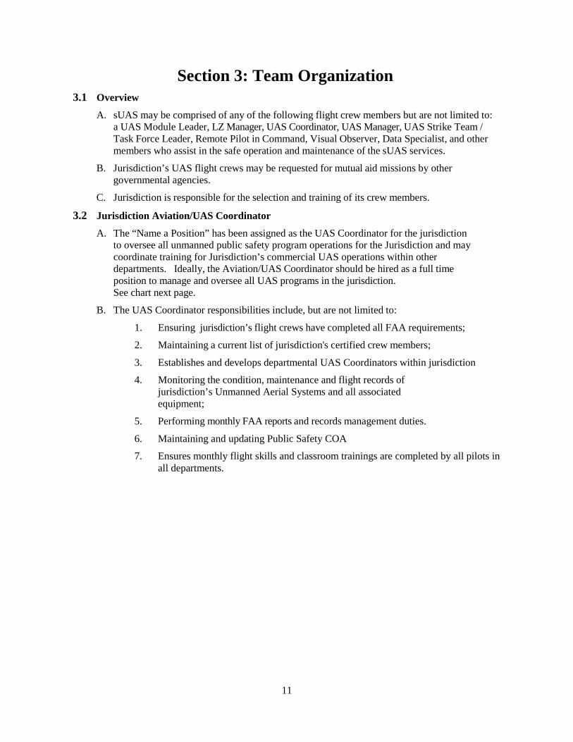
3.2 Jurisdiction Aviation/UAS Coordinator
A. The “Name a Position” has been assigned as the UAS Coordinator for the jurisdiction to oversee all unmanned public safety program operations for the Jurisdiction and may coordinate training for Jurisdiction’s commercial UAS operations within other departments. Ideally, the Aviation/UAS Coordinator should be hired as a full time position to manage and oversee all UAS programs in the jurisdiction. See chart next page.
B. The UAS Coordinator responsibilities include, but are not limited to:
1. Ensuring jurisdiction’s flight crews have completed all FAA requirements;
2. Maintaining a current list of jurisdiction's certified crew members;
3. Establishes and develops departmental UAS Coordinators within jurisdiction
4. Monitoring the condition, maintenance and flight records of jurisdiction’s Unmanned Aerial Systems and all associated equipment;
5. Performing monthly FAA reports and records management duties.
6. Maintaining and updating Public Safety COA
7. Ensures monthly flight skills and classroom trainings are completed by all pilots in all departments.

12
Jurisdiction UAS Management Chart
3.3 UAS Manager
A. This position is the conduit between a UAS vendor (under federal contract/agreement) and an Incident Management Team (IMT). The UAS Manager coordinates vendor UAS missions with operations, air operations, and planning personnel and is the designated government official (ACOR/PI) for the UAS contract/agreement.
B. This position is utilized to coordinate contract UAS operations with the air operations branch, planning section, participating aircraft, aerial supervision, and ground personnel. This position is activated when contract UAS services are requested for an incident.
3.4 UAS Module/Team Leader
A. This position leads a group of Remote Pilots/VO’s, LZ Managers, Data Specialists or other crew members on an incident and provides a single point of contact for UAS operations/data processing to incident leadership in the field. A typical UAS module consists of at least one remote pilot, one visual observer, one Module/Team Leader and possibly a data specialist or LZ Manager.
B. A UAS Module/Team Leader is a supervisory position. The UAS Module Leader or his/her designee, represents his/her agency and is responsible for the administrative and on-scene supervisory functions related to his/her agencies or department’s UAS equipment and crew while on scene at an incident.
C. The Module/Team Leader’s tactical responsibilities may include but are not limited to the overseeing and managing of the following:
13
1. Located with Field Command to act as a Liaison for the UAS branch. Receives mission assignments and forwards those assignments to the pilots or LZ Manager in the field.
2. May reach back to Jurisdiction Coordinator for additional UAS resources.
3. Manage takeoff / landing zones anytime there are three or more aircraft operating in the same airspace if an LZ Manager is not on scene. Module/Team Leader will have to locate with flight crew, not at command. At least until an LZ Manager arrives.
2. Airspace separation assurance standards between aircraft to include both manned and unmanned operations.
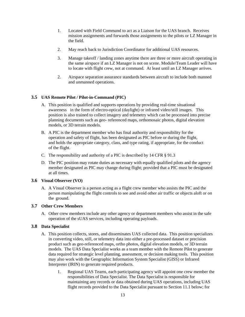
3.5 UAS Remote Pilot / Pilot-in-Command (PIC)
A. This position is qualified and supports operations by providing real-time situational awareness in the form of electro-optical (daylight) or infrared video/still images. This position is also trained to collect imagery and telemetry which can be processed into precise planning documents such as geo- referenced maps, orthomosaic photos, digital elevation models, or 3D terrain models.
B. A PIC is the department member who has final authority and responsibility for the operation and safety of flight, has been designated as PIC before or during the flight, and holds the appropriate category, class, and type rating, if appropriate, for the conduct of the flight.
C. The responsibility and authority of a PIC is described by 14 CFR § 91.3
D. The PIC position may rotate duties as necessary with equally qualified pilots and the agency member designated as PIC may change during flight; provided that a PIC must be designated at all times.
3.6 Visual Observer (VO)
A. A Visual Observer is a person acting as a flight crew member who assists the PIC and the person manipulating the flight controls to see and avoid other air traffic or objects aloft or on the ground.
3.7 Other Crew Members
A. Other crew members include any other agency or department members who assist in the safe operation of the sUAS services, including operating payloads.
3.8 Data Specialist
A. This position collects, stores, and disseminates UAS collected data. This position specializes in converting video, still, or telemetry data into either a pre-processed dataset or precision product such as geo-referenced maps, ortho photos, digital elevation models, or 3D terrain models. The UAS Data Specialist works as a team member with the Remote Pilot to generate data required for strategic level planning, assessment, or decision making tools. This position may also work with the Geographic Information System Specialist (GISS) or Infrared Interpreter (IRIN) to generate required products.
1. Regional UAS Teams, each participating agency will appoint one crew member the responsibilities of Data Specialist. The Data Specialist is responsible for maintaining any records or data obtained during UAS operations, including UAS flight records provided to the Data Specialist pursuant to Section 11.1 below; for

14
directing third party request for open records concerning a member agency to that agency; and for performing such other duties as appropriate or needed.
3.9 UAS LZ Manager
A. Is in charge of the landing zone. LZ Manager is required position anytime there are three or more aircraft flying from the same landing/takeoff zone.
B. It is the job of the LZ Manager to coordinate altitude separation between aircraft with the pilots and manage air traffic landing and takeoff operations.
C. The LZ Manager will receive mission assignments and assign those missions to the appropriate pilots.
Response Organization Chart

15
Section 4 - Airspace Authority 4.1 Authority Identification
A. As governmental entities, member agencies may choose to operate under the Small UAS Rule, 14 CFR Part 107 ("Part 107"), or conduct public aircraft operations under a public training or jurisdictional COA.
B. The PIC will determine the appropriate airspace authority for each flight operation based on the type of airspace, time of day and any other pertinent circumstances.
C. The PIC, VO and crewmembers will follow the rules of the chosen airspace authority, including any approved waivers, for each operation.
4.2 Controlled Airspace
A. Operations in Class B, Class C, or Class D airspace, or within the lateral boundaries of the surface Class E airspace designated for an airport, are not allowed unless prior authorization is received from ATC.
B. When operating in controlled airspace, the PIC must be aware of all traffic patterns and approach corridors to runways and landing areas.
C. The PIC must avoid operating anywhere that the presence of the UAS may interfere with the operations at the airport, such as approach corridors, taxiways, runways, or helipads.
D. The PIC must yield right-of-way to all other aircraft, including aircraft operating on the surface of the airport.
4.3 Data Reporting
A. Documentation of all operations associated with UAS activities is required regardless of the airspace in which the UAS operates.
B. Reporting of all sUAS activities conducted under an approved COA or waiver shall be reported monthly to the FAA unless otherwise required by the COA or waiver. Unless otherwise required the following information must be submitted:
1. The number of flights conducted under the COA or waiver;
2. Aircraft operational hours per flight;
3. Ground control station operational hours in support of each flight;
4. Pilot duty time per flight;
5. Equipment malfunctions (hardware/software) affecting either the aircraft or ground control station;
6. Deviations from ATC instructions and/or Letters of Agreement/Procedures;
7. Operational/coordination issues;
8. The number and duration of lost link events per aircraft per flight.
9. Coordinates and address of flights

16
Section 5 - Flight Crew Qualifications 5.1 PIC Qualifications
A. All pilots who will be flying Jurisdiction missions shall be properly trained by either manufacturer representatives or instructors as designated by the Jurisdiction. The UAS pilots will meet all conditions of the (COA) issued by the FAA. The pilots will have a current working knowledge of the air space intended for operations, Air Traffic Control communication requirements, specific UAS aerodynamic factors, and the ability to obtain and interpret weather. All pilots must meet the following flight experience requirements and be current with their flight log entries. The minimum training and certification requirements for a PIC are as follows:
1. Basic Flight Operations Training. All pilots must successfully complete and pass the 40 hour Basic Flight Operations Training/Curriculum for UAS as approved by the jurisdiction. Pilots must obtain their Remote 107 Pilot Certificate with a UAS rating issued by the FAA.
2. Mission Training. All pilots must undergo Mission Training to increase specific core competencies in all UAS operations, systems and roles. This training is in addition to Basic Flight Operations Training.
3. Valid driver’s license.
5.2 Proficiency
A. In order to accomplish required currency training, pilots shall participate in 4 hours of monthly training, at a minimum.
B. Recurrent training is not limited to actual pilot/observer skills, but includes knowledge of all pertinent UAS and aviation matters.
C. All members within the UAS flight crew shall read the current COA and maintain proficiency in their operator/observer abilities.
D. At a minimum, the PIC must have attended two UAS trainings and conducted three takeoffs (launch) and three landings (recovery) with the specific UAS aircraft type within the previous 90 days prior to flying an operational mission. Members who do not have documented training or flight time for the preceding 90 days shall demonstrate proficiency before performing pilot/observer duties during a mission.
E. The PIC must pass a recurrent aeronautical knowledge test within 24 calendar months of passing either an initial or other recurrent aeronautical knowledge test.
F. Failure to maintain/prove proficiency can result in removal from UAS operations.
5.3 VO Qualifications
A. The minimum training and certification requirements for a VO are as follows:
1. Completion of a training course for the safe flight of aircraft, including the responsibilities described in 14 CFR Part 91 §91.111, §91.113 and §91.115, regarding cloud clearance, flight visibility, and the pilot controller glossary, including standard ATC phraseology and communication;
2. Valid driver license.

17
5.4 Crew Resource Management
A. The AHJ will confirm that CRM training is current for all participating crewmembers before flying operational or training missions.
B. The CRM training must consist of initial training, as well as CRM recurrent training during every recurrent training cycle, not to exceed a 12 month interval between initial training and recurrent training or between subsequent recurrent training sessions.
5.5 Restrictions
A. No person may serve as a PIC, person manipulating the controls, VO or other crew member if he or she:
1. Consumed any alcoholic beverage within the preceding 8 hours;
2. Is under the influence of alcohol;
3. Has a blood alcohol concentration of 0.04 percent or greater; and/or
4. Is using a drug, whether prescription, over-the-counter, recreational, or illegal that affects the person’s ability to safely operate the aircraft and/or participate in the sUAS operational mission.
B. It is the responsibility of the PIC, person manipulating the controls, VO, or other crew member to determine whether he/she is unable to participate in a UAS operation pursuant to Section 5.E.1. However, the Crew Leader and/or Incident Commander of the incident for which UAS services are provided, may require the PIC, person manipulating the controls, VO, or other crewmember to cease participation in a sUAS operation if he/she has a reasonable suspicion that such person may be prohibited from participation pursuant to Section 5.E.1.
C. No PIC or VO may participate in UAS activities that exceed 16 continuous operation hours in a 24 hour period.
18
Section 6 -Aircraft Airworthiness and Maintenance 6.1 Airworthiness Certification
A. The AHJ is responsible for determining that the unmanned aircraft used by its pilots are airworthy.
B. All unmanned aircraft must be operated in strict compliance with all provisions and conditions contained in the Airworthiness Safety Release, including all documents and provisions referenced in any applicable COA applications or Part 107 waivers.
6.2 Maintenance
A. The AHJ is responsible for the maintenance of all sUAS owned by the Fire Department. Any sUAS owned by other city departments will have a designated member to perform aircraft maintenance.
B. sUAS maintenance includes scheduled and unscheduled overhaul, repair, inspection, modification, replacement, and system software upgrades of the sUAS and its components necessary for flight.
6.3 Configuration Control
A. A configuration control program must be in place for hardware and/or software changes made to the UAS to ensure continued airworthiness.
B. Software changes to the aircraft and control station as well as hardware system changes are classified as major changes that must be documented as part of the normal maintenance procedures.
C. Each aircraft that has a major change in software or hardware configuration must be test flown on a test range to confirm the airworthiness of the sUAS.
6.4 Preflight Inspections
A. Before each flight, the PIC must inspect the sUAS to ensure that it is in a condition for safe operation, such as inspecting for equipment damage or malfunction(s).
B. The preflight inspection should include a visual or functional check of the following items, as applicable:
1. Visual condition inspection of the UAS components;
2. Airframe structure, all flight control surfaces, and linkages;
3. Registration markings, for proper display and legibility;
4. Moveable control surface(s), including airframe attachment point(s);
5. Servo motor(s), including attachment point(s);
6. Propulsion system, including powerplant(s), propeller(s), motor(s), ducted fan(s), etc.;
7. Verify all systems (e.g., aircraft and control unit) have an adequate energy supply for the intended operation and are functioning properly;
8. Avionics, including control link transceiver, communication/navigation equipment, and antenna(s);
9. Calibrate UAS compass prior to any flight;

19
10. Control link transceiver, communication/navigation data link transceiver, and antenna(s);
11. Display panel, if used, is functioning properly;
12. Check ground support equipment, including takeoff and landing systems, for proper operation;
13. Check that control link correct functionality is established between the aircraft and the CS;
14. Check for correct movement of control surfaces using the CS;
15. Check onboard navigation and communication data links;
16. Check flight termination system, if installed;
17. Check fuel for correct type and quantity;
18. Check battery levels for the aircraft and CS;
19. Check that any equipment, such as a camera, is securely attached;
20. Verify communications with sUAS and that the sUAS has acquired GPS location from at least 4 satellites;
21. Start the sUAS propellers to inspect for any imbalance or irregular operation;
22. Verify all controller operation for heading and altitude;
23. If required, verify any noted obstructions that may interfere with the sUAS; and
24. At a controlled altitude, fly within range of any interference and recheck all controls and stability.
6.5 Maintenance Records
A. Member agencies or jurisdiction shall keep documentation of any maintenance, repair, modification, overhaul or replacement of a system component for each sUAS.
B. Member agencies or jurisdiction should keep record of time-in-service for sUAS components (e.g., airframe, batteries, etc.) at the time of maintenance, repair, modification, overhaul, or replacement procedure(s).
C. Maintenance records should be retrievable from either hardcopy and/or electronic logbook format for future reference.
6.6 Payload Restrictions
A. Any payload attached must be shown not to adversely affect the flight characteristics or controllability of the aircraft.
B. No sUAS may carry hazardous materials.
C. No sUAS may carry weapons.
6.7 Storage
A. The AHJ shall store the aircraft in a controlled environment in accordance with manufacturer recommendations.

20
Section 7 - Typing 7.1 Physical Characteristics:
A. UAS are built in a multitude of configurations, which makes classification difficult. For the purpose of emergency response, the following classification applies. Certain aircraft are specialized and will not fit this classification.
Type Configuration Endurance Data Collection Altitude (agl)
Equipped Weight (lbs.)
Typical Sensors
1 Fixed Wing
Rotorcraft
6-24 hrs.
NA
3,000-5,000’
NA
>55
NA
EO/IR/Multi- Spectral, Lidar,
*
2 Fixed Wing Rotorcraft
1-6 hrs.
20-60 min.
1,200-3,000’
400-1200’
15-55
15-55 EO/IR/Multi-
Spectral, Lidar,
3 Fixed Wing
Rotorcraft
20-60 min.
20-60 min.
400-1200’
<400’
5-14
5-14 EO/IR Video
and Stills
4
Fixed wing Up to 30 400-1200’ <5 EO/IR Video and
Rotorcraft Up to 20 min. <400’ < 5 Stills
*Contracted aircraft sensors will be determined by the contract specifications.
7.2 Operational Characteristics:
A. Type 1 and 2:
1. These aircraft will be generally operated by contractors and provide strategic situational awareness (SA) and incident mapping.
2. Fixed wing aircraft typically operate above all other incident aircraft
3. Communications are maintained with the UAS crew on the assigned Victor (AM) or air to ground (FM) frequencies.
4. All type 1 and 2 contract fixed wing aircraft will be equipped with Mode C transponders.
5. Typical aircraft are the Scan Eagle, Aerosonde, or MLB Superbat.
6. Typical rotorcraft include but are not limited to the DJI M600.
B. Type 3 and 4:
1. These aircraft may are generally agency operated and perform tactical SA or mapping missions.
2. They are carried and flown on the emergency scene at relatively low levels (200’ agl)
3. Communications are maintained with the UAS crew on the assigned air to ground (FM) frequency with the UAS Operator.

21
4. Most do not carry transponders or AFF equipment.
5. Typical aircraft include but are not limited to DJI Mavic, DJI Inspire series, DJI Phantom series and the DJI M100, M200, M210.
C. Sensor payloads are variable but typically include daylight (electro-optical), thermal, or mapping cameras. Type 1 and 2 UAS may carry multiple camera types in a gimbaled configuration.
7.3 Call Signs:
A. UAS Remote Pilots will follow established incident communications protocols and will make radio calls with the following information:
1. Unmanned Aircraft
2. Configuration (fixed or rotor-wing)
3. Type
4. Agency/Interagency assigned aircraft number.
B. Call Sign Examples:
1. “Unmanned R41” (Rotor Wing, Type 4 UAS, Agency/Interagency #1)
2. “Unmanned F12” (Fixed Wing, Type 1 UAS, Agency/Interagency #2)
3. “Unmanned R23” (Rotor Wing, Type 2 UAS, Agency/Interagency#3)

22
Section 8 - UAS Operations 8.1 Coordination Requirements
A. Operations in uncontrolled (Class G) airspace may be conducted without ATC permission.
B. In controlled airspace, the operational details must be coordinated, including NOTAM information for which Operational Area(s) ("OPAREA(s)") will be used that day, UAS PIC name, and a cell/land telephone number to call in the event of an emergency, with the ATC having authority.
C. In controlled airspace outside of the AHJ the PIC or Coordinator will obtain a waiver by filing an SGI. This can be done by contacting:
1. FAA System Operations Support Center (SOSC)
a) 202-267-8276
b) Email Address: [email protected]
8.2 Notice to Airmen (NOTAM)
A. A NOTAM should be issued whenever flight operations are scheduled or required by a COA or Part 107 waiver.
B. A NOTAM may be accomplished by contacting the NOTAM Flight Service Station at (1-877-487-6867) or https://www.1800wxbrief.com/Website/#!/ not more than 72 hours in advance, but not less than 48 hours prior to the operation, unless otherwise authorized as a special provision.
C. The issuing agency will require the:
1. Name and address of the pilot filing the NOTAM request;
2. Location, altitude, or operating area;
3. Radial off nearest airport.
4. Time and nature of the activity.
8.3 Operational Limitations
A. The sUAS must remain within VLOS of the PIC and the person manipulating the controls. Alternatively, the sUAS must remain within VLOS of the visual observer.
B. At all times the UAS must remain close enough to the PIC and the person manipulating the controls of the sUAS for those people to be capable of seeing the aircraft with vision unaided by any device other than corrective lenses.
C. Unless otherwise authorized as a special provision, all operations must be conducted in visual meteorological conditions (VMC) following visual flight rules (VFR) weather minimums.
D. sUAS may not operate over any person not directly participating (nonparticipants) in the operation.
E. VO(s) must be used at all times.
F. FPV cameras cannot satisfy “see-and-avoid” requirement, but can be used as long as the requirement is satisfied in other ways.
G. Operations will occur at a maximum altitude of 400 feet AGL or, if higher than 400 AGL, remain within 400 feet of a structure unless otherwise approved by waiver.
23
H. No person may act as a PIC or VO for more than one sUAS operation at one time.
8.4 Safety of Flight
A. All pilots are responsible for halting or canceling UAS activity if, at any time, the safety of persons or property on the ground or in the air may be jeopardized.
B. Any VO responsible for performing see-and-avoid requirements for the sUAS must have and maintain communication with the PIC.
C. The use of multiple successive VOs (daisy chaining) is prohibited unless otherwise authorized by special provision.
8.5 Prior to Flight
A. The PIC must conduct an assessment of the operating environment. The safety risk assessment must include the following:
1. Local weather conditions,
2. Local airspace and any flight restrictions,
3. The location of persons and property on the surface, and
4. Other ground hazards.
B. The PIC must conduct a pre-takeoff briefing as applicable prior to each launch. The briefing should include, but is not limited to, the:
1. Contents of any applicable COA or Part 107 waiver,
2. Altitudes to be flown,
3. Mission overview including handoff procedures,
4. Frequencies to be used,
5. Flight time, including reserve fuel requirements,
6. Contingency procedures to include lost link, divert, and flight termination,
7. Emergency procedures,
8. Roles and responsibilities of each person involved in the operation, and
9. Hazards unique to the flight being flown.
C. The PIC must ensure there is sufficient power for the sUAS to continue controlled flight operations to a normal landing.
D. The PIC must ensure all necessary documentation is available for inspection, including the PIC’s remote pilot certificate, aircraft registration (if required), and COA (if applicable).
8.6 Sterile Cockpit Procedures
A. Critical phases of flight include all ground operations involving:
1. Taxi (movement of fixed wing aircraft under its own power on the surface of an LZ);
2. Take-off and landing (launch or recovery);
3. All other flight operations in which safety or mission accomplishment might be compromised by distractions.

24
4. If any distractions occur during critical phases of the flight operation the flight shall be aborted until the distractions can be appropriately mitigated.
B. No crewmember may perform any duties during a critical phase of flight not required for the safe operation of the aircraft.
C. No crew member may engage in, nor may any PIC permit, any activity during a critical phase of flight which could:
1. Distract any crewmember from the performance of his/her duties; or
2. Interfere in any way with the proper conduct of those duties.
D. The pilot and/or the PIC must not engage in any activity not directly related to the operations of the aircraft.
E. The use of cell phones or other electronic devices by crew members is restricted to communications pertinent to the operational control of the sUAS and any required communications with ATC.
8.7 Night Operations A. The PIC must be in place 30 minutes prior to night operations to ensure dark adaptation.
B. VOs will be positioned in appropriate locations during all UAS flight operations.
C. Vision aides may not be used as the primary means for visual observation duties, but are permitted to augment the VOs visual capability.
D. All sUAS flown during civil twilight or at night will be equipped with light emitting diode (LED) position lights installed to comply with 14 CFR §91.209 unless otherwise approved by special provision.
8.8 Observers during Scenario Based Training A. Observers will receive a safety briefing that addresses the mission intent, non-interference
with any mission personnel, and emergency procedures in the event of an incident or accident.
B. Observers will be directed to and contained within a specific observation point that ensures risk of injury is minimized and assures non-interference with the sUAS training mission.
C. A designated flight crew member will ensure that Observers do not engage in conversations, discussions, interviews or distractions of any mission personnel from the performance of his/her duties or interfere in any way with the proper conduct of those duties.
D. Flight Operations will limit the number of Observers to that which can be adequately monitored and protected by the personnel resources onsite.

25
Section 9 - Launch and Recovery 9.1 Launch and Recovery
A. Prior to take off the UAS will be programed to allow it to return to home if the signal is lost from the transmitter.
B. When the UAS is deployed to meet an approved mission task, it shall be recovered within the same general area if possible.
C. A designated safe area of at least 25 feet shall be maintained during lift off between UAS’s and personnel.
D. UAS’s should not be flown within unsafe distances to any object or person
9.2 Weather – A. The PIC shall verify the weather conditions in the immediate area of operations. A local source
of weather may be utilized, the internet, phone application or may be observed on site. The UAS will not be flown outside the weather minimums identified by the manufacture or the approved Certificate of Waiver/Authorization (COA) by the FAA. The PIC shall have final determination of risk due to weather and authority over any mission.
9.3 Hazards to the Public – A. The PIC shall make every effort to ensure that flight operations will not pose any undue risk to
the public not directly involved with the effort. The PIC shall have final determination of risk to the public and authority over any launch of his/her own aircraft. In all cases, the UAS will not be flown over persons that is in violation of the FAA approved COA.
9.4 Hazards to property – A. The PIC shall make every effort to ensure that flight operations will not pose any undue risk to
any property in the area involved with the effort. The PIC shall have final determination of risk to the property and authority over launch of his/her own aircraft. . In all cases, the UAS will not be flow over property that is in violation of the FAA approved COA.
9.5 Hazards to personnel – A. The PIC shall make every effort to ensure that flight operations will not pose any undue risk to
the personnel directly involved with the effort. The PIC shall have final determination of risk to the public and authority over any launch of his/her aircraft.
9.6 Proximity to controlled airspace – A. Operations inside any controlled airspace B,C,D shall only be performed after notifying ATC
and if necessary obtaining an SGI.

26
Section 10 - Launch and Landing Zones 10.1 Launch Site Selection
A. Launch site selection shall be driven by safety first and foremost. Selection of launch sites will be considered based upon:
1. Ability to maintain adequate buffer zones between aircraft and personnel. The PIC shall maintain a buffer of at least 25 feet for VTOL aircraft between aircraft operations and all non-essential personnel. A designated individual can be identified as a safety officer to ensure the safety of the launch and recovery area.
2. Environmental Assessment- No launches shall occur until all environmental assessments have been considered. The PIC has the final authority to abort any launch based upon hazards to the environment, themselves, or other personnel in the area.
3. The PIC shall select a launch site that ensures UA departures are not in or over populated areas.
10.2 Landing Site and Alternate Sites A. Primary Landing site –
1. Typically the primary landing site shall be the same as the launch site. The PIC has final authority for any approaches to the primary site and may wave off any approach deemed unsafe.
B. Alternate landing sites
1. The PIC shall designate at least one alternate landing site. In the event that the primary landing site is deemed unsafe, procedures to utilize the secondary site will be invoked.
C. Mission Abort Sites
1. The PIC may optionally designate an “abort site” whereby the aircraft may be “dumped” in an emergency situation. The abort site shall be so far removed as to provide absolute minimal risk should the aircraft be required to vacate airspace in an emergency. The UA may be flown to this site and inserted without regard to the safety of the aircraft or flight equipment should the PIC deem it necessary.
D. Landing Safety & Crowd control
1. All landing sites shall be maintained and operated as the launch sites. Personnel shall maintain a buffer of at least 25 feet for VTOL aircraft between aircraft operations and all non- essential personnel.
27
10.3 Landing and Takeoff A. Each Pilot will utilize their own launch/landing pad within the LZ for taking off and landing.
This will give each pilot a specific launch/landing point to operate off of within the landing zone and will help prevent collisions.
B. Takeoff –
1. Pilots will obtain mission, altitude and lift off approval from Module Leader or LZ Manager before taking off. If no Module Leader or LZ Manager is assigned then pilots will coordinate operations together. All Type II and Type IV aircraft shall take off vertically until they reach 15 feet AGL at which time they will verify all controls are working correctly. Once verification is complete the aircraft will proceed to the assigned altitude and proceed with mission. Each pilot will utilize a separate landing pad with markings for takeoff.
C. Landing –
1. If Module Leader or LZ Manager is assigned pilots will obtain permission to land before approaching landing zone. If no Module Leader or LZ Manager is assigned pilots will coordinate operations together. All aircraft shall approach landing site at assigned altitude, maintain that altitude above landing point/pad and then descend to 15 feet AGL. At 15 feet AGL pilot will hover the aircraft and verify all persons or obstructions are clear of landing pad. Once it is determined it is safe to land, the aircraft will descend until on the landing pad. Each pilot will utilize a separate landing pad with markings for landing.

28
Section 11 - Emergency/Contingency Procedures 11.1 Lost Link / GPS Procedures
A. Lost link is an interruption or loss of the control link between the control station and the unmanned aircraft, preventing control of the aircraft resulting in the UAS performing pre-set lost link procedures such as the following:
1. In the event of a lost link while operating in controlled airspace, which cannot be re- established within 10 seconds, a designated crewmember will immediately notify the appropriate ATC.
B. When possible, lost link and lost GPS procedures should comply with the following:
1. The aircraft autopilot will enter a lost link mode within 10 seconds of the lost link condition being detected, return to the LZ or other defined lost link waypoint within the sUAS OP AREA, and land.
2. If the aircraft loses GPS, the PIC should immediately attempt to land the aircraft in a safe location by controlling it manually or landing at the current location within the OP AREA.
3. If both GPS and data link are lost, the aircraft must automatically land at the current position.
4. The UAS lost link mission should avoid transit or orbit over populated areas.
11.2 Emergency or Fly-Away Procedures A. In the event of a fly-away or other emergency scenario while operating in controlled airspace,
designated crew member will immediately notify ATC or nearest controlling facility.
B. The crewmember will state PIC intentions, and provide the following:
1. The nature of the emergency,
2. Last known UAS position, altitude, and direction of flight, and
3. Maximum remaining flight time.
11.3 Lost Sight
A. If a VO loses sight of the UAS, the VO will notify the PIC immediately.
B. If the UAS is visually reacquired promptly, the mission may be continued. If not, the PIC must immediately abort the flight and land the UAS.
11.4 Lost Communications A. The PIC must land the UAS if communication with the VO is lost and the PIC cannot gain
VLOS.

29
Section - 12 Incident/Accident/Mishap Reporting 12.1 FAA Reporting Criteria
A. All accidents/mishaps involving UAS operations, where any of the following occur, shall be reported to the FAA:
1. Fatal injury, where the operations of a UAS results in a death occurring within 30 days of the accident/mishap;
2. Serious injury, where the operation of a UAS results in a hospitalization of more than 48 hours, the fracture of any bone (except for simple fractures of fingers, toes, or nose), severe hemorrhage or tissue damage, internal injuries, or second or third degree burns;
3. Total unmanned aircraft loss;
4. Substantial damage to the UAS where there is damage to the airframe, power plant, or onboard systems that must be repaired prior to further flight. Damage to property, other than the unmanned aircraft greater than $500.
B. When operating under a COA, any incident/mishap that results in an unsafe/abnormal operation shall be reported to the FAA including, but not limited to:
1. A malfunction or failure of the unmanned aircraft’s on-board flight control system (including navigation);
2. A malfunction or failure of the ground control station flight control hardware or software (other than loss of control link);
3. A power plant failure or malfunction;
4. An in-flight fire;
5. An aircraft collision;
6. Any in-flight failure of the unmanned aircraft’s electrical system requiring use of alternate or emergency power to complete the flight;
7. A deviation from any provisions contained in the COA;
8. A deviation from an ATC clearance and/or Letter(s) of Agreement/Procedures;
C. A lost control link event resulting in a fly-away or execution of a preplanned/unplanned lost link procedure.
D. All incidents or accidents are required to be reported to the FAA within 10 days, unless such incident or accident occurs while operating under a COA, which must be reported as soon as reasonable practicable and before any additional flights occur.
12.2 FAA Report Submission A. Any incident or accident that occurs while operating under a COA can be reported to the FAA
via the CAPS On-Line Accident/Incident Report and initially reported via email at:
B. All other incident/accident reports may be submitted to the FAA Regional Operations Center by phone at 817-222-5006 or electronically at http://www.faa.gov/about/office_org/field_offices/fsdo/.

30
C. The report should include the following information:
1. UAS PIC’s name and contact information;
2. UAS PIC’s FAA airman certificate number;
3. UAS registration number issued to the aircraft, if required;
4. Location of the accident;
5. Date of the accident;
6. Person(s) injured and extent of injury, if any or known;
7. Property damaged and extent of damage, if any or known; and
8. Description of what happened.
12.3 NTSB Reporting Criteria A. All accidents/mishaps involving UAS operations, where any of the following occur,
shall be reported to the NTSB in compliance with 49 CFR §830.2:
1. Any person suffers death or serious injury;
2. Flight control system malfunction or failure such as a fly-away;
3. Inflight fire;
4. Aircraft collision in flight;
5. More than $25,000 damage to objects other than the aircraft;
6. Release of all or a portion of a propeller blade from an aircraft, excluding release caused solely by ground contact.
B. All incidents or accidents are required to be reported to the NTSB as soon as reasonably practicable and before any additional flights occur.
12.4 NTSB Report Submission A. All incident/accident reports may be reported to the NTSB’s Response Operations Center at
844-373-9922 .
B. The report should include the following information:
1. Type and registration marks on the UAS;
2. Name of owner and operator of the UAS;
3. Name of the PIC;
4. Date and time of the accident;
5. Location of the operating area; and
6. Nature of the accident, the weather and the extent of damage to the UAS.

31
Section 13 - Information Management 13.1 Collection
A. All UAS flights will be documented and reported by the Pilot or Data Specialist within 5 days.
B. At a minimum, flight records should include:
1. Date and time,
2. Operational area,
3. Name of the PIC,
4. Name of the VO if applicable,
5. Aircraft identification,
6. Flight time,
7. Any incidents/accidents/mishaps, and
8. Purpose of the flight.
C. All UAS flights conducted for any purpose other than training or demonstration shall be documented in a report and either reference or be filed by the pilot.
13.2 Retention A. Jurisdiction maintains retention of any aircraft/flight records or data, including but not limited
to images and/or videos and flight telemetry that are collected by the UAS equipment.
B. Records and data, including images and videos, will be retained pursuant to existing record retention of the department.
C. Collection and Use: The Jurisdiction shall only collect information using UAV/UAS to the extent that such collection or use is consistent with and relevant to an authorized purpose of the Jurisdiction and is compliant with the Texas Privacy Act.
D. Information collected using UAV/UAS that may contain personally identifiable Information (PII) shall not be retained for more than 60 days from recording unless retention of the information is determined to be necessary to an authorized mission of the Jurisdiction, is maintained in a system of records covered by the Privacy Act, or is required to be retained for a longer period by any other applicable law or regulation. The following UAS retention schedule shall be adhered to:
1. Trainings/Non-Response 90 days
2. Incident Response 2 years
3. Incident Response or Training (personnel Injured) 5 years
4. Structure Fires/Hazmat Incidents/Disasters 5 years
5. Criminal Investigations 10 years

32
13.3 Dissemination
A. All UAS-related information will only be provided pursuant to a request for public records, which request will be processed in accordance with the Open Records Act and any rules or policies of the member agency receiving the request adopted in accordance with the Open Records Act.
B. Jurisdiction members will not post, transmit, or otherwise disseminate any records or data, including images or videos, obtained via UAS for personal use without the consent of the department.
C. UAS collected information that is not maintained in a system of records covered by the Privacy Act shall not be disseminated outside of the Jurisdiction unless dissemination is required by law, or fulfills an authorized purpose and complies with Jurisdiction requirements.

33
Appendix A: Flight Checklist

34
Appendix B:
Beaufort Wind Scale

35
Appendix C: Aircraft Hand Signals

36
Appendix D:
Contingency Plan Checklist

37
Appendix E:
Mission Planning Profile

38
Appendix F: Training and Standards The test methods and process for evaluating system capabilities and/or operator proficiency are roughly the same. Start by performing repeated trials using elemental test methods to measure individual capabilities and improve muscle memory for basic skills. Then graduate to performing repeatable combinations and sequences of test methods to measure trade-offs in capabilities for a given system configuration. Then embed the test methods into training scenarios to quantitatively compare baseline capabilities with actual readiness to perform tasks within uncontrolled environments. This helps measure the degradation of performance due to the environmental variables within scenarios.
The following content will serve as examples of training apparatus which reflect both:
• Low cost / easily constructed training apparatus to be assembled and used at any work place. These apparatus serve as an alternative where space and funding may be an
• The National Institute of Standards and Technology Standard Test Methods for Small Unmanned Aircraft Systems (sUAS)
Both of the above options are ideal establishing standards and quantitative measurements that focus training, measure operator proficiency, assess airworthiness of particular aircraft, and assist with informed decision making for future purchases.
Individuals wishing to be qualified as a Public Safety Remote Pilot are required to perform the following standards set forth by the National Fire Protection Association’s (NFPA) Standard for Small Unmanned Aircraft Systems (sUAS) used for Public Safety Operations job performance requirements (JPR’s).
Qualified Public Safety Remote Pilots will meet or exceed the minimum proficiency level of “Proficient” established by NIST Standard Test Methods for the following apparatus.
1. Maneuvering: Hold Position and Altitude
2. Maneuvering: Orbit a Point
3. Maneuvering: Fly Straight and Level
4. Maneuvering: Avoid Obstacles (Figure-8s)
5. Maneuvering: Land Accurately
6. Payload Functionality: Point and Zoom Cameras
7. Payload Functionality: Identify Objects
8. Payload Functionality: Inspect Objects
9. Payload Functionality: Map Wide Areas
10. Payload Functionality: Drop
These are the notations to report for each test trial. Use of a common test form is optional:
• Make/Model/Configuration of the system to be tested.
• Name (or Code) of the pilot in charge of the test trial.
• Organization and location at which the test trial is being conducted.
• Date (yyyy-mm-dd) and time (2400) of the test trial.
• Pertinent environmental conditions as measured just prior to the test trial using appropriate devices (e.g., wind speed and direction, temperature, humidity, pressure, altitude, etc.).

39
• Ratio of successful tasks to faults (tasks: faults). This ratio can be used to determine the reliability of the system or proficiency of the pilot.
• Average result of any specific task metrics across the number of successful tasks completed.
• Total elapsed time (minutes) adding up all sequential timer increments in the test trial.
• Calculated average rate of successful tasks completed (tasks/minute). This number can be compared to others with varying levels of confidence depending on the number of successful tasks completed.
Link to NIST:
www.nist.gov/el/intelligent-systems-division-73500/response-robots/aerial-systems

40
Figure of Eight
Purpose
• The Purpose of this test method is to quantitatively evaluate the operator's ability to maintain orientational direction while flying in a figure of eight pattern.
Metrics
● Completion of maximum repetitions
● Average time per repetition
Duration
● 10 minutes
Apparatus
● This test apparatus consists of two cones equally spaced four feet apart.
● Performed in either GPS or attitude mode.
● A designated takeoff / landing zone will be identified.
Procedure
1. Place the aircraft at starting location on designated takeoff / landing zone.
2. Launch the aircraft from the designated area and travel in a counterclockwise rotation.
3. Maintain preferred flight elevation either above or below eye level.
4. The aircraft must pass around each cone in a very controlled manner.
5. Five repetitions will be completed and operator will change orientational direction by rotating platform 90 degrees.
6. Repeat steps until 0, 90, 180, and 270 degrees have been flown.
7. After the completion of five repetitions in each direction (0, 90, 180,and 360 degrees) reverse orientation and complete procedure in a clockwise orientation.
Fault condition
● Failure to maintain elevation
● Inability to fly around each cone Failure to use controlled manner of flight

41
Follow the Path
Purpose
• The Purpose of this test method is to quantitatively evaluate the operator's ability follow a path of travel while maintaining orientational direction.
Metrics
● Completion of maximum repetitions
● Average time per repetition
Duration
● 10 minutes
Apparatus
● This test apparatus consist of five cones in a linear formation equally spaced three feet apart.
● Performed in either GPS or attitude mode.
● A designated takeoff and landing area will be identified.
Procedure
1. To begin place the aircraft on the designated takeoff / landing zone.
2. Launch the aircraft and fly over the cones in a straight line then land the aircraft in the designated takeoff / landing zone on the other end of the line.
3. The first direction of travel will be with the nose of the aircraft facing forward in the direction of travel (0 degree orientation).
4. Maintain preferred flight elevation either above or below eye level.
5. Five repetitions will be completed and operator will change orientational direction by rotating nose of aircraft 90 degrees
6. Repeat steps until 0, 90, 180, and 270 degrees have been flown.
7. After the completion of five repetitions in each direction (0, 90, 180,and 360 degrees) reverse orientation and complete procedure in a clockwise orientation.
Fault condition
● Failure to maintain elevation
● Inability to fly over each cone
● Failure to use controlled manner of flight

42
Four Corners
Purpose
• The purpose of this test method is to quantitatively evaluate the operator's ability to maintain orientational flight.
Metrics
● Completion of maximum repetitions
● Average time per repetition
Duration
● 10 minutes
Apparatus
● This test apparatus consist of four cones in a square formation equally spaced four feet apart.
● Performed in either GPS or attitude mode.
● A designated takeoff and landing zone will be identified.
Procedure
1. To begin place the aircraft on the designated takeoff / landing zone..
2. Launch the aircraft from designated launch / landing zone and travel in a counterclockwise direction over the cones. The first direction of travel will be with the nose of the aircraft facing forward in the direction of travel (0 degree orientation).
3. Maintain preferred flight elevation either above or below eye level.

43
4. The aircraft must pass over the top of each cone in a very controlled manner.
5. Five repetitions will be completed and operator will change orientational direction by rotating nose of aircraft 90 degrees
6. Repeat steps until 0, 90, 180, and 270 degrees have been flown.
7. After the completion of five repetitions in each direction (0, 90, 180,and 360 degrees) reverse orientation and complete procedure in a clockwise orientation.
Fault condition
● Failure to maintain elevation
● Inability to fly over each cone
● Failure to use controlled manner of flight

44
Serpentine
Purpose
• The Purpose of this test method is to quantitatively evaluate the operator's ability avoid contacting obstacles while traveling in a serpentine path.
Metrics
● Completion of maximum repetitions
● Average time per repetition
Duration
● 10 minutes
Apparatus
● This test apparatus consist of five cones with attached pool noodles to create vertical post. Each pool noodle will need a ¾” pipe run through the center of it and then placed in the top of the cone. The cones should be spaced in a straight line three feet apart (see diagram)
● Performed in either GPS or attitude mode.
● Prop guards are recommended
● A designated takeoff and landing zone will be identified.
Procedure
1. To begin place the aircraft on the designated takeoff / landing zone.
2. Launch the aircraft from the designated takeoff / landing zone. The nose of the aircraft will be facing forward (0 degree orientation).
3. Direction of travel will be serpentine around each cone beginning in a counterclockwise direction.
4. Maintain preferred flight elevation either above or below eye level.
5. Five repetitions will be completed and operator will change orientational direction by rotating the aircraft 90 degrees.
6. Repeat steps until 0, 90, 180, and 270 degrees have been flown.
7. After the completion of five repetitions in each direction (0, 90, 180,and 360 degrees) reverse orientation and complete procedure in a clockwise orientation.
Fault condition
● Failure to maintain elevation
● Inability to fly around each cone
● Failure to use controlled manner of flight

45
Payload Drop Accuracy
Description:
This test method evaluates the capability to drop a payload accurately from a defined altitude. The system performs a series of drops on a metered platform from different altitudes. The payloads can be weighted surrogates or operationally significant delivery items.
Metric:
• Average Radius from Center in Centimeters (Inches)
Duration:
• 40-80 minutes to complete 10-20 tasks.
Apparatus:
• Landing Platform (Quantity 1).: 2.4 x 2.4 m (96in x 96 in) square platform with 10 cm (4 in) circular bands to measure the landing radius.
• Bucket Targets (Quantity 4): 20 cm (8 in) diameter or 7.5 liter (2-gallon) white buckets with internal black rings around the inside bottom and a 7.5 cm (3 in) black letter to identify the target. The bucket size should be considered based on the designated drop altitude.
• Surrounding Lines (Quantity: 4): Concentric chalk/paint lines on the ground at 2m (6.5ft), 4m (13ft), and 6m (20ft) to capture less accurate drops.
Preparation:
• See general Trial Preparation guidance.
Procedure

46
1. Establish a hover position SOUTH of the landing platform at least 6 m (20 ft) range from the platform and at the designated drop altitude AGL. See concentric markings on the ground to ensure the distance.
2. Start the trial timer and onboard video recording if available.
3. Move to directly over the drop zone and refine position.
4. Announce a loud audible warning of intent to drop along with a countdown to inform personnel on the ground.
5. Drop the payload and pause the timer.
6. Land the aircraft on any available space on or near the landing platform.
7. Note on the form the outer-most concentric ring occupied by any ground contact of the payload. This is the measurement of the payload drop radius. Contact with the lines, if not exceeded, shall be considered within the smaller concentric ring. 8. Repeat steps 1-7 from each of four different directions, North-East-South- West, until the timer expires. Reset the timer and continue if necessary to complete at least 10 repetitions.
9. Report on the form:
a. Each payload drop radius (cm) b. Total number of tasks completed successfully (tasks). c. Total elapsed time including all timer increments (minutes).
Fault Conditions
• Touching the apparatus, ground, or surrounding safety containment
structure during a repetition.