Publ-6576 Prod Cat 11
299
The European Products Catalogue 2011 controls, hvac & refrigeration products
Transcript of Publ-6576 Prod Cat 11

8/6/2019 Publ-6576 Prod Cat 11
http://slidepdf.com/reader/full/publ-6576-prod-cat-11 1/298
The European Products Catalogue2011
controls, hvac & refrigeration products

8/6/2019 Publ-6576 Prod Cat 11
http://slidepdf.com/reader/full/publ-6576-prod-cat-11 2/298

8/6/2019 Publ-6576 Prod Cat 11
http://slidepdf.com/reader/full/publ-6576-prod-cat-11 3/298
A more comfortable,
safe and sustainable world

8/6/2019 Publ-6576 Prod Cat 11
http://slidepdf.com/reader/full/publ-6576-prod-cat-11 4/298

8/6/2019 Publ-6576 Prod Cat 11
http://slidepdf.com/reader/full/publ-6576-prod-cat-11 5/298
Company profileJohnson Controls has expanded remarkably sinceProfessor Warren Johnson founded the companyto manufacture his invention, the electric roomthermostat. Since its start in 1885, Johnson Controls hasgrown into a global leader in automotive experience,building efficiency and power solutions.The company provides innovative automotive interiorsthat help make driving more comfortable, safe and
enjoyable. For buildings, it offers products and servicesthat optimize energy use and improve comfort andsecurity. Johnson Controls also provides batteries forautomobiles and hybrid electric vehicles, along withsystems engineering and service expertise.
Our visionA more comfortable,
safe and sustainable world.
Our valuesIntegrityHonesty, fairness, respect, and safety are of the utmostimportance.
Customer SatisfactionOur future depends on us helping to make ourcustomers successful. We are proactive and easy to dobusiness with. We offer expert knowledge and practicalsolutions, and we deliver on our promises.
Employee EngagementWe foster a culture that promotes excellentperformance, teamwork, inclusion, leadership andgrowth.
InnovationWe believe there is always a better way. We encouragechange and seek the opportunity it brings.
SustainabilityThrough our products, services, operations andcommunity involvement, we promote the efficient useof resources to benefit all people and the world.

8/6/2019 Publ-6576 Prod Cat 11
http://slidepdf.com/reader/full/publ-6576-prod-cat-11 6/298

8/6/2019 Publ-6576 Prod Cat 11
http://slidepdf.com/reader/full/publ-6576-prod-cat-11 7/298
the european products catalogue 2011
Manufacturer reserved the rights to change specifications without prior notice
index
hvac control products
Actuators - Linear Actuators 3
Actuators - Rotary Actuators 25
Valves 49
Sensors 79
Thermostats 101Transducers 106
building automation systems
Supervisory and Automation 111
Electronic Control Devices 145
refrigeration components
Modulating Water Valves 199Field Controllers 213
Condenser Fan Speed Controllers 224
Flow and Float Controls 234
Pressure Controls 237
Pressure Transducers 262
Temperature Controls 266
hospitality solutions
XRM - eXtended Room Management 281

8/6/2019 Publ-6576 Prod Cat 11
http://slidepdf.com/reader/full/publ-6576-prod-cat-11 8/298
the european products catalogue 2011
Manufacturer reserved the rights to change specifications without prior notice
Notes
8/6/2019 Publ-6576 Prod Cat 11
http://slidepdf.com/reader/full/publ-6576-prod-cat-11 9/298
the european products catalogue 2011
Manufacturer reserved the rights to change specifications without prior notice
index
hvac control products
Actuators - Linear Actuators for Terminal Unit Valves
VA-7010
ON/OFF Control
3
VA-7030 4
VA-707x 5
VA-7060 Proportional Control 7
VA-7450Floating and Proportional Control
8
VA-747x 9
for Plant Valves
FA-2000Floating and Proportional Control
10
FA-3000 11
MP8000Pneumatic Valve Actuators
12
PA-2000 13
RA-3000
Floating and Proportional Control
14
VA1000 15
VA-7150 16
VA-7200 17
VA-7310 18
VA-7700 19
VA7800 20

8/6/2019 Publ-6576 Prod Cat 11
http://slidepdf.com/reader/full/publ-6576-prod-cat-11 10/298
the european products catalogue 2011
Manufacturer reserved the rights to change specifications without prior notice
Notes

8/6/2019 Publ-6576 Prod Cat 11
http://slidepdf.com/reader/full/publ-6576-prod-cat-11 11/298
3
the european products catalogue 2011
hvac control products
Actuators
For further information and additional models see Product Bulletin
The VA-7010 electric ON/OFF actuator provides a two-position(open-closed) control and can easily be mounted with a threadedmounting nut onto VG4000 and VG5000 terminal unit valves.
A lever at the side of the actuator housing can be used to manually opena 2-way PDTO valve, or the normally closed port of a 3-way valve.
Features z 24 VAC and 230 VAC models
z ON/OFF Control
z Manual lever
z Threaded mounting nut M28 x 1.5
z Factory mounted cable 1.5 m
VA-7010
ON/OFF Control
Linear Actuators for Terminal Unit Valves
Dimensions in mm
Ordering CodesSupply Voltage
(50/60 Hz)ActionControl
MinimumForce Stroke Full Stroke Time
ProtectionClass
PowerConsumption
VA-7010-8101 24 VACON/OFF 90 N
3 mm(max. 5 mm)
10 s (Actuator stem extends)
5 s (Actuator stem retracts)IP 40 7 VA
VA-7010-8103 230 VAC
8/6/2019 Publ-6576 Prod Cat 11
http://slidepdf.com/reader/full/publ-6576-prod-cat-11 12/298
the european products catalogue 2011
hvac control products
Actuators
4
For further information and additional models see Product Bulletin
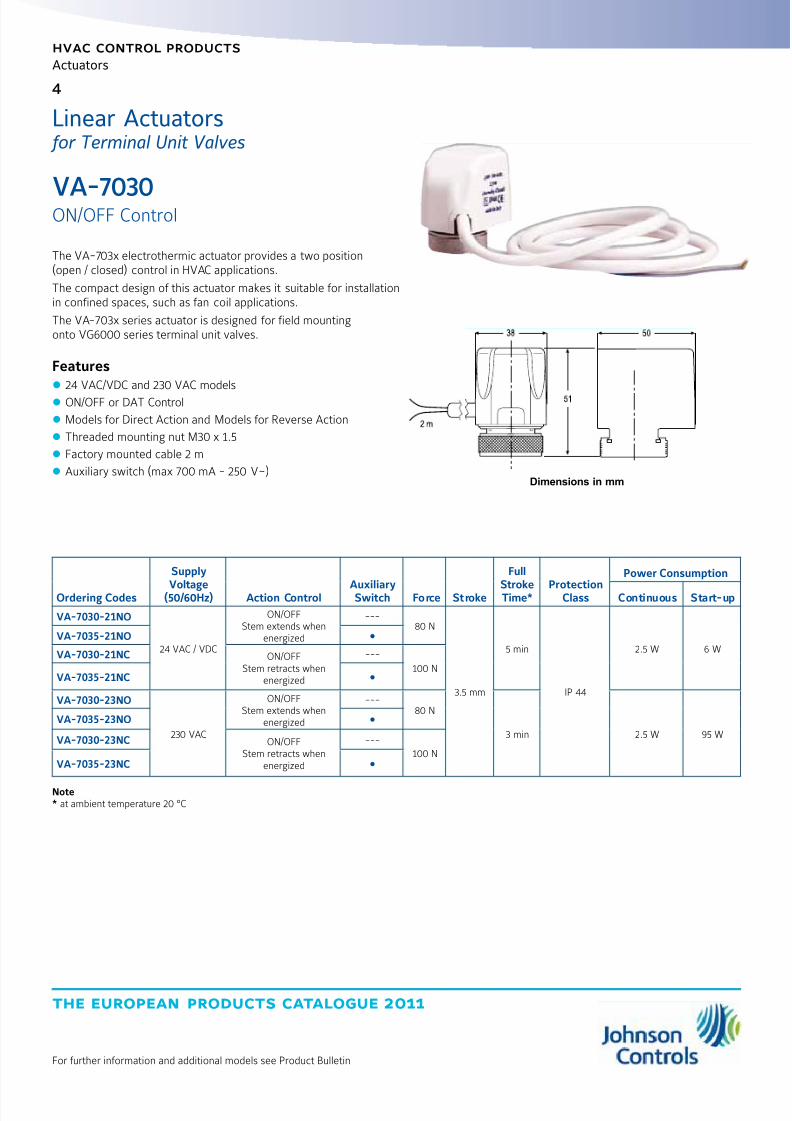
The VA-703x electrothermic actuator provides a two position(open / closed) control in HVAC applications.
The compact design of this actuator makes it suitable for installationin confined spaces, such as fan coil applications.
The VA-703x series actuator is designed for field mountingonto VG6000 series terminal unit valves.
Features z 24 VAC/VDC and 230 VAC models
z ON/OFF or DAT Control
z Models for Direct Action and Models for Reverse Action
z Threaded mounting nut M30 x 1.5
z Factory mounted cable 2 m
z Auxiliary switch (max 700 mA - 250 V~)
VA-7030
ON/OFF Control
Ordering Codes
Supply
Voltage(50/60Hz) Action Control AuxiliarySwitch Force Stroke
Full
StrokeTime* ProtectionClass
Power Consumption
Continuous Start-up
VA-7030-21NO
24 VAC / VDC
ON/OFFStem extends when
energized
---80 N
3.5 mm
5 min
IP 44
2.5 W 6 WVA-7035-21NO
VA-7030-21NC ON/OFFStem retracts when
energized
---
100 NVA-7035-21NC
VA-7030-23NO
230 VAC
ON/OFFStem extends when
energized
---80 N
3 min 2.5 W 95 W
VA-7035-23NO
VA-7030-23NC ON/OFFStem retracts when
energized
---
100 NVA-7035-23NC
Note* at ambient temperature 20 °C
Dimensions in mm
Linear Actuators for Terminal Unit Valves

8/6/2019 Publ-6576 Prod Cat 11
http://slidepdf.com/reader/full/publ-6576-prod-cat-11 13/298
5
the european products catalogue 2011
hvac control products
Actuators
For further information and additional models see Product Bulletin
The VA-707x series terminal unit valve actuators provide ON/OFF andDAT control in HAVC application.
The compact design of these actuators make them suitable forinstallations in confined spaces, such as fan-coil applications.
The VA-707x actuators are designed for field mounting onto allJohnson Controls terminal unit valves: VG6000, V5000, VG4000and VG5000 (see pertinent bulletins).
Moreover, thanks to an innovative fixing system, the VA-707xis suitable for almost all the terminal unit valves in the market.
Features z 24 VAC/DC and 230 VAC models
z ON/OFF or DAT Controls
z NC version (stem retracts when energized)
z NO version (stem extends when energized)
z Easy mounting solution (easy to install, no expert required)
z Factory mounted cable 2 m
VA-707x
ON/OFF Control
Linear Actuators for Terminal Unit Valves
Dimensions in mm
Ordering CodesSupplyVoltage
ActionControl Force Stroke Factory Setting
Mounting
ThreadProtection
Class Packaging
Power
Consumption
C o n t i n u o u s
S t a r t - u p
VA-7071-2124 VAC/VDC
ON/OFF orDAT
125 N 4.5 mm
Normally Closed(stem retracts when
energized)2 m cable lenght
M28x1.5
IP 54
Singlepackaged incarton box
3 W6 W
(230 mA)max
VA-7078-21 M30x1.5
VA-7071-23230 VAC
M28x1.5
VA-7078-23 M30x1.5
VA-7071-01D24 VAC/VDC
Normally Closed(stem retracts when
energized)Cable not included.Must be ordered
separately
M28x1.5
Bulk pack50 pcs 2.5 W
36 W
(150 mA)max
VA-7078-01D M30x1.5
VA-7071-03D230 VAC
M28x1.5
VA-7078-03D M30x1.5
VA-7070-2124 VAC/VDC Normally Open
(stem extends whenenergized)
2 m cable lenght
M28x1.5
Singlepackaged incarton box
3 W6 W
(230 mA)max
VA-7077-21 M30x1.5
VA-7070-23230 VAC
M28x1.5
VA-7077-23 M30x1.5
VA-7070-01D24 VAC/VDC
Normally Open(stem extends when
energized)Cable not included.Must be ordered
separately
M28x1.5
Bulk pack50 pcs
2.5 W36 W
(150 mA)max
VA-7077-01D M30x1.5
VA-7070-03D230 VAC
M28x1.5
VA-7077-03D M30x1.5
8/6/2019 Publ-6576 Prod Cat 11
http://slidepdf.com/reader/full/publ-6576-prod-cat-11 14/298
the european products catalogue 2011
hvac control products
Actuators
6
For further information and additional models see Product Bulletin
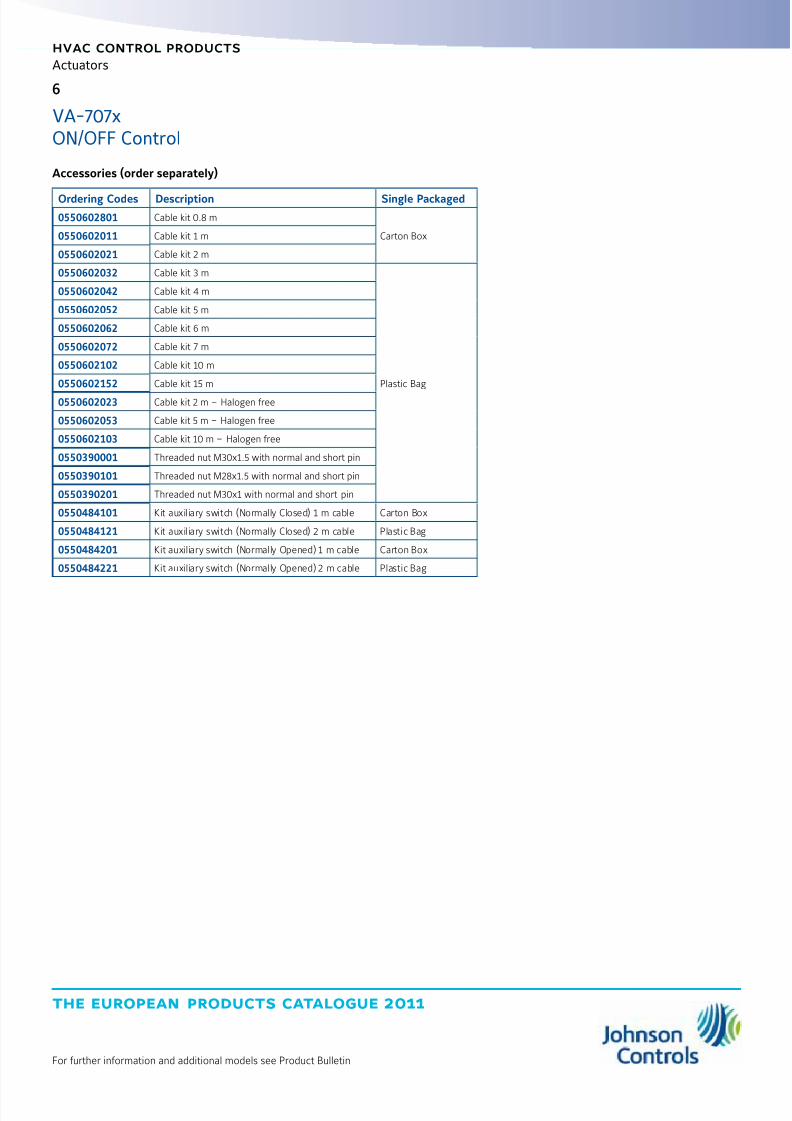
VA-707xON/OFF Control
Accessories (order separately)
Ordering Codes Description Single Packaged
0550602801 Cable kit 0.8 m
Carton Box0550602011 Cable kit 1 m
0550602021 Cable kit 2 m
0550602032 Cable kit 3 m
Plastic Bag
0550602042 Cable kit 4 m
0550602052 Cable kit 5 m
0550602062 Cable kit 6 m
0550602072 Cable kit 7 m
0550602102 Cable kit 10 m
0550602152 Cable kit 15 m
0550602023 Cable kit 2 m – Halogen free
0550602053 Cable kit 5 m – Halogen free
0550602103 Cable kit 10 m – Halogen free
0550390001 Threaded nut M30x1.5 with normal and short pin
0550390101 Threaded nut M28x1.5 with normal and short pin
0550390201 Threaded nut M30x1 with normal and short pin
0550484101 Kit auxiliary switch (Normally Closed) 1 m cable Carton Box
0550484121 Kit auxiliary switch (Normally Closed) 2 m cable Plastic Bag
0550484201 Kit auxiliary switch (Normally Opened) 1 m cable Carton Box
0550484221 Kit auxiliary switch (Normally Opened) 2 m cable Plastic Bag

8/6/2019 Publ-6576 Prod Cat 11
http://slidepdf.com/reader/full/publ-6576-prod-cat-11 15/298
7
the european products catalogue 2011
hvac control products
Actuators
For further information and additional models see Product Bulletin
The VA-706x actuators provide Proportional control in HVAC applications.The compact design of these actuators make them suitable forinstallations in confined spaces, such as fan-coil applications.
The VA-706x actuators are designed for field mounting onto VG4000,VG5000 and V5000 terminal unit valves.
Features z 24 VAC/DC
z Proportional Control
z Configurable to Direct and Reverse Action
z Threaded mounting nut (M28 x 1.5 for VG5000 or M30 x 1.5 for V5000)
z Factory mounted cable 2 m
VA-7060
Proportional Control
Models A Ø B C Ø
VA-7060-21 32 10 M28 x 1,5
VA-7067-21 34 11 M30 x 1,5
Ordering Codes
SupplyVoltage
(50/60Hz)ActionControl Force Stroke Factory Setting
ProtectionClass
Power Consumption
Continuous Start-up
VA-7060-21 24 VAC or24 VDC
Proportional 125 N 4.5 mmDirect Acting
stem extend when energizedIP 44 3 W
6 W
(230 mA) maxVA-7067-21
Dimensions in mm
Linear Actuators for Terminal Unit Valves
8/6/2019 Publ-6576 Prod Cat 11
http://slidepdf.com/reader/full/publ-6576-prod-cat-11 16/298
the european products catalogue 2011
hvac control products
Actuators
8
For further information and additional models see Product Bulletin
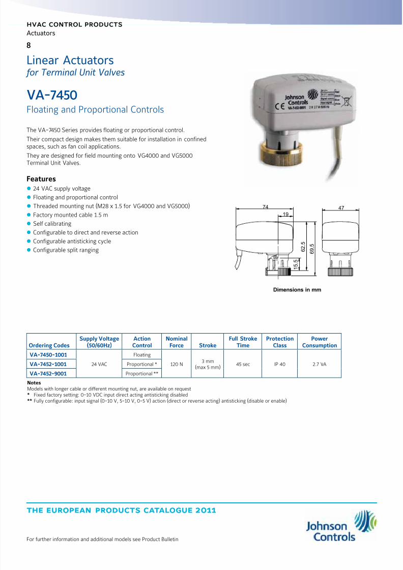
The VA-7450 Series provides floating or proportional control.
Their compact design makes them suitable for installation in confinedspaces, such as fan coil applications.
They are designed for field mounting onto VG4000 and VG5000Terminal Unit Valves.
Features z 24 VAC supply voltage
z
Floating and proportional control z Threaded mounting nut (M28 x 1.5 for VG4000 and VG5000)
z Factory mounted cable 1.5 m
z Self calibrating
z Configurable to direct and reverse action
z Configurable antisticking cycle
z Configurable split ranging
VA-7450
Floating and Proportional Controls
Ordering CodesSupply Voltage
(50/60Hz)ActionControl
NominalForce Stroke
Full StrokeTime
ProtectionClass
PowerConsumption
VA-7450-1001
24 VAC
Floating
120 N3 mm
(max 5 mm)45 sec IP 40 2.7 VAVA-7452-1001 Proportional *
VA-7452-9001 Proportional **
NotesModels with longer cable or different mounting nut, are available on request* Fixed factory setting: 0-10 VDC input direct acting antisticking disabled
** Fully configurable: input signal (0-10 V, 5-10 V, 0-5 V) action (direct or reverse acting) antisticking (disable or enable)
74
19
6 2 .
5
1 5 .
5
6 9 .
5
47
Dimensions in mm
Linear Actuators for Terminal Unit Valves
8/6/2019 Publ-6576 Prod Cat 11
http://slidepdf.com/reader/full/publ-6576-prod-cat-11 17/298
9
the european products catalogue 2011
hvac control products
Actuators
For further information and additional models see Product Bulletin
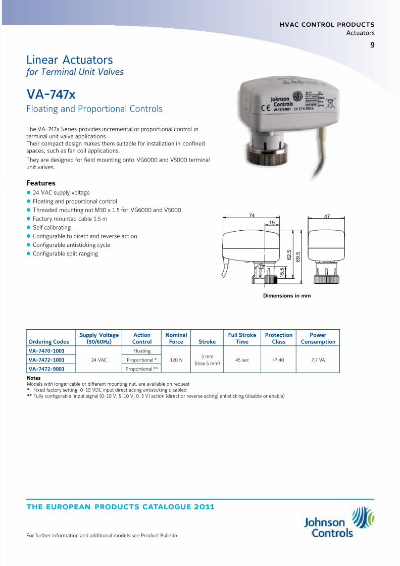
The VA-747x Series provides incremental or proportional control interminal unit valve applications.Their compact design makes them suitable for installation in confinedspaces, such as fan coil applications.
They are designed for field mounting onto VG6000 and V5000 terminalunit valves.
Features z 24 VAC supply voltage
z Floating and proportional control
z Threaded mounting nut M30 x 1.5 for VG6000 and V5000
z Factory mounted cable 1.5 m
z Self calibrating
z Configurable to direct and reverse action
z Configurable antisticking cycle
z Configurable split ranging
VA-747x
Floating and Proportional Controls
Ordering CodesSupply Voltage
(50/60Hz)ActionControl
NominalForce Stroke
Full StrokeTime
ProtectionClass
PowerConsumption
VA-7470-1001
24 VAC
Floating
120 N3 mm
(max 5 mm)45 sec IP 40 2.7 VAVA-7472-1001 Proportional *
VA-7472-9001 Proportional **
NotesModels with longer cable or different mounting nut, are available on request* Fixed factory setting: 0-10 VDC input direct acting antisticking disabled
** Fully configurable: input signal (0-10 V, 5-10 V, 0-5 V) action (direct or reverse acting) antisticking (disable or enable)
Dimensions in mm
74
19
6 2 .
5
1 5 .
5
6 9 .
5
47
Linear Actuators for Terminal Unit Valves

8/6/2019 Publ-6576 Prod Cat 11
http://slidepdf.com/reader/full/publ-6576-prod-cat-11 18/298
the european products catalogue 2011
hvac control products
Actuators
10
For further information and additional models see Product Bulletin
The FA-2000 series electric actuators are available for 3-point controlor with electronic positioner for 0…10 V or 0…20 mA control. It providesa fully variable valve aperture, a power failure spring return safetymechanism and an electrically operated manual override.Three models of the FA-2000 are available.The FA-22 (“failsafe” position down = stem fully extended)and FA-25 (“failsafe” position up = stem fully retracted):this model pair has a 25 mm stroke and a minimum of 2400 N thrust.The FA-23 (“failsafe” position down) and FA-26 (“failsafe” position up):this model pair has a 42 mm stroke of and a minimum thrust of 2200 N.The FA-24 (“failsafe” position down) and FA-27 (“failsafe” position up):this model pair has a stroke of 13 mm and 2000 N minimum thrust.The actuator can be combined with VG8000 (H, N, V) series inaccordance with the maximum close-off pressure ratings specified.The FA-2000, when delivered as a single unit, is pre-set to facilitateinstallation with minimum adjustment; it is also available with a variety of options such as auxiliary switches and feedback potentiometers
Features z Power failure mechanism (Spring Return)
z Visible calibration ring on stem coupling
z Positioner with adjustable starting point, span and direct/reverse action
z Electrically operated manual override z Quick-fit coupling clamp
FA-2000
Floating and Proportional Control
Ordering Codes *
SupplyVoltage
(50 Hz)ActionControl
Spring ReturnFunction
NominalThrust
NominalStroke
ProtectionClass
PowerConsumption
EmergencyShut of speed
FA-22xx-7511 230 VAC
FloatingandProportional
Stem fully extended
2.4 kN 25 mm
IP 54
5 VA ≤ 89
FA-22xx-7516 24 VAC 6.1 VA
≤ 81FA-25xx-7511 230 VACStem fully retracted
5 VA
FA-25xx-7516 24 VAC 6.1 VA
FA-23xx-7411 230 VACStem fully extended
2.2 kN 42 mm
5 VA
≤ 201FA-23xx-7416 24 VAC 6.1 VAFA-26xx-7411 230 VAC
Stem fully retracted5 VA
FA-26xx-7416 24 VAC 6.1 VA
FA-24xx-7111 230 VACStem fully extended
2 kN 13 mm
5 VA
≤ 51FA-24xx-7116 24 VAC 6.1 VA
FA-27xx-7111 230 VACStem fully retracted
5 VA
FA-27xx-7116 24 VAC 6.1 VA
Note
* xx = 00 None 04 135 W feedback potentiometer
01 2 Auxiliary switches 40 Built-in electronic positioner 0...10 V / 0(4)...20 mA (not for 230 V models)
02 2 KW feedback potentiometer 41 Built-in electronic positioner 0...10 V / 0(4)...20 mA(not for 230 V models) and 2 auxiliary switches03 2 KW feedback potentiometer and 2 auxiliary switches
Dimensions in mm
FA-22, FA-25 FA-23, FA-24, FA-26, FA-27
162
Ø 120
Ø 54
Ø 120
541 With positioner 586162
Ø 54
Ø 120
Ø 120
FA-23 / FA-26
575 With positioner 612
FA-24 / FA-27
511 With positioner 548
Linear Actuators for Plant Valves

8/6/2019 Publ-6576 Prod Cat 11
http://slidepdf.com/reader/full/publ-6576-prod-cat-11 19/298
11
the european products catalogue 2011
hvac control products
Actuators
For further information and additional models see Product Bulletin
The FA-3300 heavy duty series provides floating or proportional controland can be mounted with VG8000 flanged valves.
Features z 24 VAC and 230 VAC power supply
z Floating and Proportional control
z Manual override
z Special clamp coupler
z
Uses synchronous motor with calibrated pressure limit switches
FA-3000
Floating and Proportional Control
Ordering CodesSupply Voltage
(50/60Hz)ActionControl Force Stroke
Full StrokeTime
ProtectionClass
PowerConsumption
AccessoriesFactory mounted
FA-3300-7416
24 VACFloating
6000 N42 mm
(max 45)150 s IP 65
37 VA
none
FA-3303-7416 2 aux switches and 2 KW pot
FA-3304-7416 135 W pot
FA-3341-7416 Proportional 42 VA 2 aux switches
FA-3300-7411
230 VACFloating 37 VA
none
FA-3303-7411 2 aux switches and 2 KW pot
FA-3304-7411 135 W pot
FA-3341-7411 Proportional 42 VA 2 aux switches
ø 130
ø 54.1
10
ø 54
2 0 0
100 60
ø145 1 5 6
3
1 6
Dimensions in mm
Linear Actuators for Plant Valves
8/6/2019 Publ-6576 Prod Cat 11
http://slidepdf.com/reader/full/publ-6576-prod-cat-11 20/298
the european products catalogue 2011
hvac control products
Actuators
12
For further information and additional models see Product Bulletin
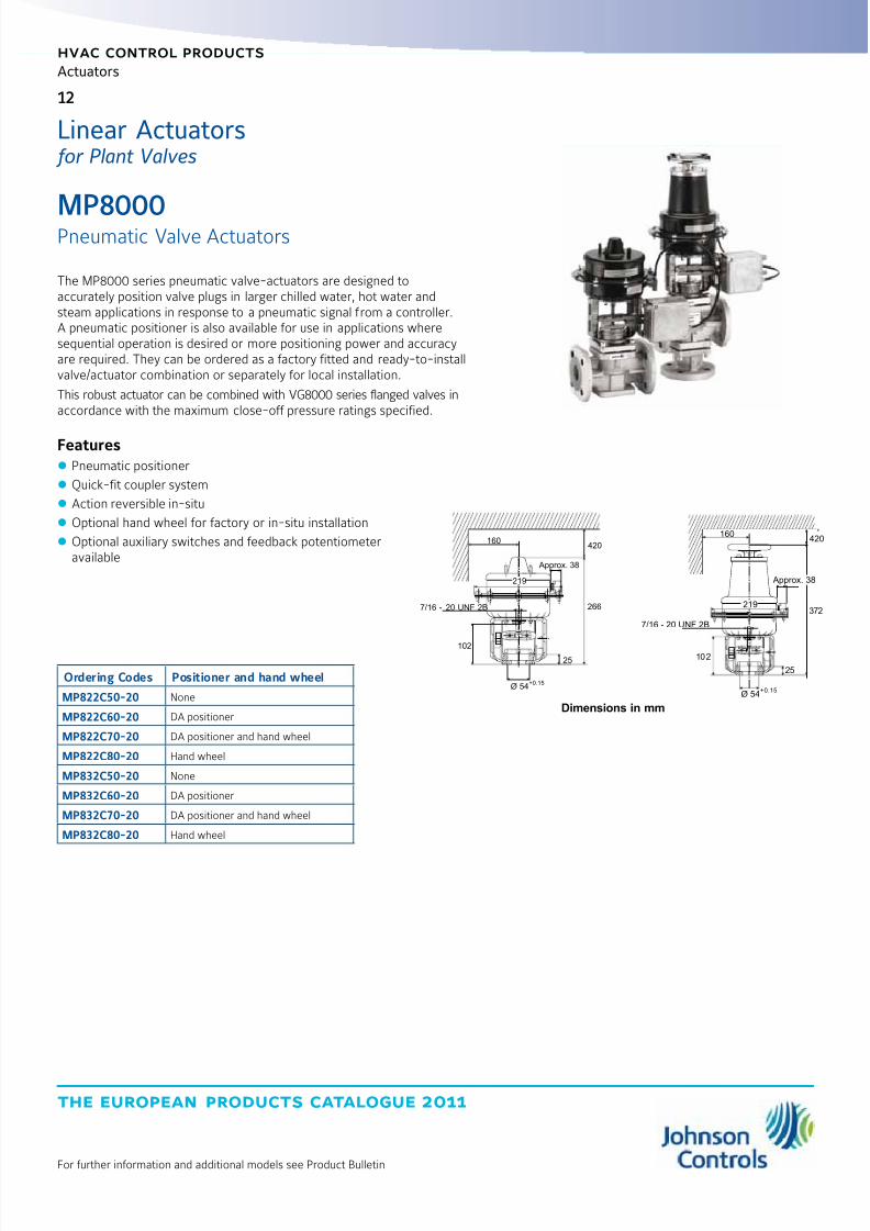
The MP8000 series pneumatic valve-actuators are designed toaccurately position valve plugs in larger chilled water, hot water andsteam applications in response to a pneumatic signal from a controller.A pneumatic positioner is also available for use in applications wheresequential operation is desired or more positioning power and accuracyare required. They can be ordered as a factory fitted and ready-to-installvalve/actuator combination or separately for local installation.
This robust actuator can be combined with VG8000 series flanged valves inaccordance with the maximum close-off pressure ratings specified.
Features z Pneumatic positioner
z Quick-fit coupler system
z Action reversible in-situ
z Optional hand wheel for factory or in-situ installation
z Optional auxiliary switches and feedback potentiometeravailable
MP8000
Pneumatic Valve Actuators
Ordering Codes Positioner and hand wheel
MP822C50-20 None
MP822C60-20 DA positioner
MP822C70-20 DA positioner and hand wheel
MP822C80-20 Hand wheel
MP832C50-20 None
MP832C60-20 DA positioner
MP832C70-20 DA positioner and hand wheel
MP832C80-20 Hand wheel
Approx. 38
7/16 - 20 UNF 2B
219
Ø 54+0.15
420
266
10225
160
Dimensions in mm
160
Ø 54+0.15
7/16 - 20 UNF 2B
273
201
52
420
Approx. 38
219
Linear Actuators for Plant Valves

8/6/2019 Publ-6576 Prod Cat 11
http://slidepdf.com/reader/full/publ-6576-prod-cat-11 21/298
13
the european products catalogue 2011
hvac control products
Actuators
For further information and additional models see Product Bulletin
The PA-2000 Pneumatic Valve Actuators Series is available for ON/OFFControl.
The actuator can be combined with VG8000 and VG8300 series inaccordance with the maximum close-off pressure ratings specified.
The fail safe position of the PA-2000 can be changed in-situ with aconversion kit.
Featuresz Manual override
z Reversible action in-situ
z Accessories available
PA-2000
Pneumatic Valve Actuators
Ordering Codes* Handwheel Spring RangeDiaphram
Area Stroke
PA-20x0-32y2 --- 20 - 50 kPa150 cm2 13 mm
PA-21x0-32y7 70 - 100 kPa
PA-20x0-33y2 --- 20 - 50 kPa300 cm2 25 mm
PA-21x0-33y7 70 - 100 kPa
PA-20x0-36y2 --- 20 - 50 kPa
600 cm2
42 mmPA-21x0-36y7 70 - 100 kPa
PA-20x0-37y2 --- 20 - 50 kPa25 mm
PA-21x0-37y7 70 - 100 kPa
Notes* = x: 0 = Without Positioner
3 = With Positioner (PR10)
y: 1 = DA Actuator stem extends2 = RA Actuator stem retracts
Dimensions in mm
Linear Actuators for Plant Valves

8/6/2019 Publ-6576 Prod Cat 11
http://slidepdf.com/reader/full/publ-6576-prod-cat-11 22/298
the european products catalogue 2011
hvac control products
Actuators
14
For further information and additional models see Product Bulletin
The RA-3000 series synchronous motor-driven reversible actuators areavailable for 3-point (floating) or with electric positioner for 0...10 Vcontrol.
They feature factory calibrated pressure switches to provide specifiedclose-off ratings. These actuators are available in three sizes with1600 N, 1800 N and with 3000 N nominal force and can be used withJC flanged valves according to maximum close-off pressure ratingsspecified.
Factory fitted options, such as 2kOhm feedback potentiometer, auxiliary
switches and hand crank are available.
Features z Uses synchronous motor with pressure switches
z Special clamp coupler quick-fit systems
z Models for 3-point and proportional 0...10 VDC control
z Positioner with adjustable starting point, span, and direct/reverse action
z Active 0...10 VDC position feedback on proportional models
z Optional auxiliary switches and feedback potentiometer available
z Optional hand crank
RA-3000
Floating and Proportional Control
RA-3xxx-712x RA-3xxx-722x RA-3xxx-732x
H1 58 mm 66 mm 66 mm
Dimensions in mm
Ordering Codes* Hand Crank** Actuator Force Supply Voltage Nominal Stroke Protection Class
RA-30xx-7126 ---
1600 N
24 V, 50/60 Hz
13 mm
IP 54
RA-31xx-7126
RA-30xx-7127 ---230 V, 50/60 Hz
RA-31xx-7127
RA-30xx-7226 ---
1800 N
24 V, 50/60 Hz
25 mmRA-31xx-7226
RA-30xx-7227 ---230 V, 50/60 Hz
RA-31xx-7227
RA-30xx-7325 ---
3000 N
24 V, 60 Hz
42 mm
RA-31xx-7325
RA-30xx-7326 ---24 V, 50 Hz
RA-31xx-7326
RA-30xx-7327 ---230 V, 50 Hz
RA-31xx-7327
RA-30xx-7328 ---230 V, 60 Hz
RA-31xx-7328
Notes
* : xx = 100 None
03 2 auxiliary switches and 2 KW feedback potentiometer
41 Built-in positioner 0...10 VDC and 2 auxiliary switches (only 24 VAC models)
Linear Actuators for Plant Valves
8/6/2019 Publ-6576 Prod Cat 11
http://slidepdf.com/reader/full/publ-6576-prod-cat-11 23/298
15
the european products catalogue 2011
hvac control products
Actuators
For further information and additional models see Product Bulletin
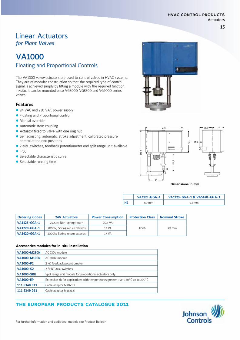
The VA1000 valve-actuators are used to control valves in HVAC systems.They are of modular construction so that the required type of controlsignal is achieved simply by fitting a module with the required functionin-situ. It can be mounted onto VG8000, VG8300 and VG9000 seriesvalves.
Features z 24 VAC and 230 VAC power supply
z Floating and Proportional control
z Manual override
z Automatic stem coupling
z Actuator fixed to valve with one ring nut
z Self adjusting, automatic stroke adjustment, calibrated pressurecontrol at the end positions
z 2 aux. switches, feedback potentiometer and split range unit available
z IP66
z Selectable characteristic curve
z Selectable running time
VA1000
Floating and Proportional Controls
VA1125-GGA-1 VA1220-GGA-1 & VA1420-GGA-1
H1 60 mm 73 mm
Ordering Codes 24V Actuators Power Consumption Protection Class Nominal Stroke
VA1125-GGA-1 2500N; Non-spring return 20.5 VA
IP 66 49 mmVA1220-GGA-1 2000N; Spring return retracts 17 VA
VA1420-GGA-1 2000N; Spring return extends 17 VA
Accessories modules for in-situ installation
VA1000-M230N AC 230V module
VA1000-M100N AC 100V module
VA1000-P2 2 KΩ feedback potentiometer
VA1000-S2 2 SPDT aux. switches
VA1000-SRU Split range unit module for proportional actuators only
VA1000-EP Extension kit for applications with temperatures greater than 140°C up to 200°C
111 6348 011 Cable adaptor M20x1.5
111 6349 011 Cable adaptor M16x1.5
2 6 2 .
5
90
230
1 1 1 .
4
14
18.5 1 3 4
75.5 H1
Dimensions in mm
Linear Actuators for Plant Valves
8/6/2019 Publ-6576 Prod Cat 11
http://slidepdf.com/reader/full/publ-6576-prod-cat-11 24/298
the european products catalogue 2011
hvac control products
Actuators
16
For further information and additional models see Product Bulletin
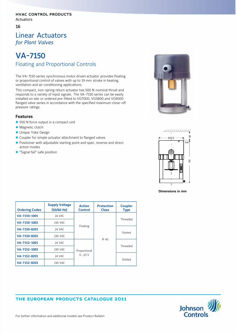
The VA-7150 series synchronous motor driven actuator provides floatingor proportional control of valves with up to 19 mm stroke in heating,ventilation and air conditioning applications.
This compact, non-spring return actuator has 500 N nominal thrust andresponds to a variety of input signals. The VA-7150 series can be easilyinstalled on site or ordered pre-fitted to VG7000, VGS800 and VG9000flanged valve series in accordance with the specified maximum close-off pressure ratings.
Features z 500 N force output in a compact unit
z Magnetic clutch
z Unique Yoke Design
z Coupler for simple actuator attachment to flanged valves
z Positioner with adjustable starting point and span, reverse and directaction modes
z “Signal fail” safe position
VA-7150
Floating and Proportional Controls
Ordering Codes
Supply Voltage
(50/60 Hz)ActionControl
ProtectionClass
CouplerType
VA-7150-1001 24 VAC
Floating
IP 40
ThreadedVA-7150-1003 230 VAC
VA-7150-8201 24 VAC
SlottedVA-7150-8203 230 VAC
VA-7152-1001 24 VAC
Proportional
0...10 V
ThreadedVA-7152-1003 230 VAC
VA-7152-8201 24 VACSlotted
VA-7152-8203 230 VAC
Dimensions in mm
IP40
Ø 97.58
0
1 5 3
Linear Actuators for Plant Valves

8/6/2019 Publ-6576 Prod Cat 11
http://slidepdf.com/reader/full/publ-6576-prod-cat-11 25/298
17
the european products catalogue 2011
hvac control products
Actuators
For further information and additional models see Product Bulletin
The VA-720x Series synchronous motor driven actuator provides floatingor proportional control of valves, with up to 19 mm stroke in heating,ventilation and air conditioning applications. This compact, non-springreturn actuator has a 1000N nominal force and responds to a variety of input signals.
The VA-7200 Series can be easily field mounted or ordered factorycoupled to VG7000, VG8000, VG9000 and VGS800 Series valves inaccordance with the specified maximum close-off pressure ratings.
Features z 1000N Force Output compact unit
z Magnetic clutch
z Signal fail ”safe position”
VA-7200
Floating and Proportional Controls
Ordering CodesSupply Voltage
(50/60 Hz) ControlMotorRating
ProtectionClass
For VG7000 Series Valves
VA-7200-100124 VAC
Floating5 W IP 42
VA-7202-1001 Proportional 0...10 VDC / 0(4)...20 mA
For VG8000 / VG9000 / VGS8000
VA-7200-820124 VAC
Floating5 W IP 42
VA-7202-8201 Proportional 0...10 VDC / 0(4)...20 mA
IP42 IP40
106 1 0 0
1 2 0
7 8
106 1 0 0
1 4 7
7 8
Dimensions in mm
Linear Actuators for Plant Valves
8/6/2019 Publ-6576 Prod Cat 11
http://slidepdf.com/reader/full/publ-6576-prod-cat-11 26/298
the european products catalogue 2011
hvac control products
Actuators
18
For further information and additional models see Product Bulletin
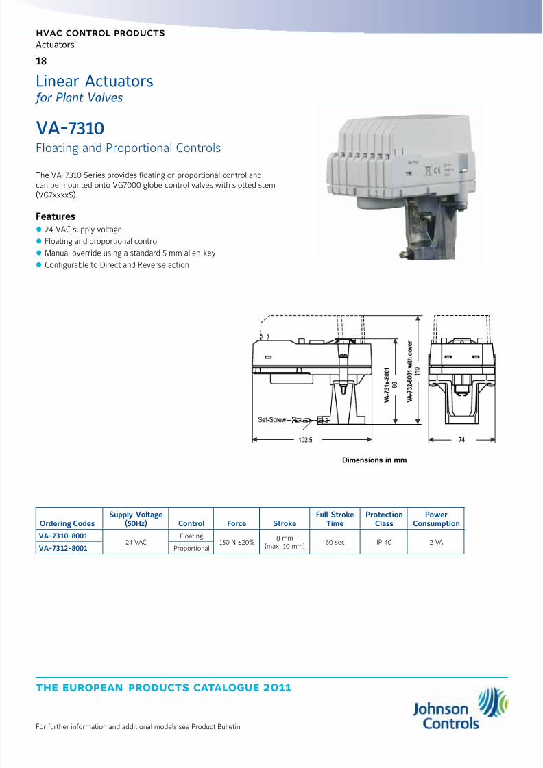
The VA-7310 Series provides floating or proportional control andcan be mounted onto VG7000 globe control valves with slotted stem(VG7xxxxS).
Features z 24 VAC supply voltage
z Floating and proportional control
z Manual override using a standard 5 mm allen key
z
Configurable to Direct and Reverse action
VA-7310Floating and Proportional Controls
Ordering CodesSupply Voltage
(50Hz) Control Force StrokeFull Stroke
TimeProtection
ClassPower
Consumption
VA-7310-8001 24 VAC Floating 150 N ±20% 8 mm(max. 10 mm)
60 sec IP 40 2 VAVA-7312-8001 Proportional
Dimensions in mm
Linear Actuators for Plant Valves

8/6/2019 Publ-6576 Prod Cat 11
http://slidepdf.com/reader/full/publ-6576-prod-cat-11 27/298
19
the european products catalogue 2011
hvac control products
Actuators
For further information and additional models see Product Bulletin
The VA-7700 series provides floating and proportional control and can bemounted onto VG7000, VGS800 and VG9000 valves.
Features z 24 VAC and 230 VAC power supply
z Floating and proportional control
z Manual override
z LED operating status display
z
Self calibrating z IP54 enclosive protection
VA-7700
Floating and Proportional Controls
Mounting onto VG7000 Series Valves
Ordering CodesSupply Voltage
(50/60Hz)ActionControl Force Stroke
Full StrokeTime
ProtectionClass
PowerConsumption
VA-7700-1001 24 VAC
Floating
500 N 20 mm 190 s IP 54
2.4 VAVA-7700-1003 230 VAC
VA-7740-1001 24 VAC
VA-7740-1003 230 VAC
VA-7706-100124 VAC Proportional 4.4 VA
VA-7746-1001
Mounting onto VGS8000 and VG9000 Series Valves
Ordering CodesSupply Voltage
(50/60Hz)ActionControl Force Stroke
Full StrokeTime
ProtectionClass
PowerConsumption
VA-7700-8201 24 VAC
Floating
500 N 20 mm 190 s IP 54
2.4 VAVA-7700-8203 230 VAC
VA-7740-8201 24 VAC
VA-7740-8203 230 VAC
VA-7706-820124 VAC Proportional 4.4 VA
VA-7746-8201
Dimensions in mm
Linear Actuators for Plant Valves

8/6/2019 Publ-6576 Prod Cat 11
http://slidepdf.com/reader/full/publ-6576-prod-cat-11 28/298
the european products catalogue 2011
hvac control products
Actuators
20
For further information and additional models see Product Bulletin
The VA78x0 spring return and non-spring return actuator with 1000 Nthrust for valves in heating, ventilation and air conditioning applicationsis available for floating (3-point) control or proportional control.All models have manual override as standard and provide strokecapabilities of 7 mm to 25 mm. Proportional models are self-calibrating.
The actuator is intended for use with Johnson Controls VG7000 andVGS800 threaded valves as well as VG9000, VG8000 and VG8300flanged valves. All valves should be fitted in accordance with themaximum close-off pressure ratings specified. Valve-actuators can
be ordered as separate units or as a factory fitted valve / actuatorcombinations.
Features z Proportional actuators are self calibrating
z All models can also be used as floating and ON/OFF actuators
z Force controlled motor shut-off
z Manual override as standard
z IP54 enclosure protection
z Delivered with fitted 1.5 m cable and wire terminals
z Status LED
z Models with optional aux. switches or 2 kW feedback potentiometer
z Control-Signal failure - stem to pre-determined positionz Stroke position indicator
z Spring return functions (VA7820 and VA7830 models)
VA7800
Floating and Proportional Controls
150 min.
212 115
2 3 1
Dimensions in mm
Linear Actuators for Plant Valves
8/6/2019 Publ-6576 Prod Cat 11
http://slidepdf.com/reader/full/publ-6576-prod-cat-11 29/298
21
the european products catalogue 2011
hvac control products
Actuators
For further information and additional models see Product Bulletin
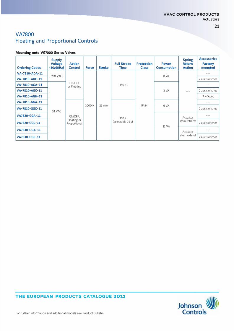
Mounting onto VG7000 Series Valves
Ordering Codes
SupplyVoltage
(50/60Hz)ActionControl Force Stroke
Full StrokeTime
ProtectionClass
PowerConsumption
SpringReturnAction
AccessoriesFactory
mounted
VA-7810-ADA-11230 VAC
ON/OFFor Floating
1000 N 25 mm
150 s
IP 54
8 VA
---
---
VA-7810-ADC-11 2 aux switches
VA-7810-AGA-11
24 VAC
3 VA
---
VA-7810-AGC-11 2 aux switches
VA-7810-AGH-11 2 KW pot
VA-7810-GGA-11
ON/OFF,Floating or
Proportional
150 s(selectable 75 s)
6 VA---
VA-7810-GGC-11 2 aux switches
VA7820-GGA-11
11 VA
Actuatorstem retracts
---
VA7820-GGC-11 2 aux switches
VA7830-GGA-11Actuator
stem extend
---
VA7830-GGC-11 2 aux switches
VA7800Floating and Proportional Controls
8/6/2019 Publ-6576 Prod Cat 11
http://slidepdf.com/reader/full/publ-6576-prod-cat-11 30/298
the european products catalogue 2011
hvac control products
Actuators
22
For further information and additional models see Product Bulletin
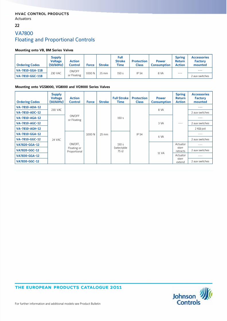
Mounting onto VGS8000, VG8000 and VG9000 Series Valves
Ordering Codes
SupplyVoltage
(50/60Hz)ActionControl Force Stroke
Full StrokeTime
ProtectionClass
PowerConsumption
SpringReturnAction
AccessoriesFactory
mounted
VA-7810-ADA-12230 VAC
ON/OFF
or Floating
1000 N 25 mm
150 s
IP 54
8 VA
---
---
VA-7810-ADC-12 2 aux switches
VA-7810-AGA-12
24 VAC
3 VA
---
VA-7810-AGC-12 2 aux switches
VA-7810-AGH-12 2 KW pot
VA-7810-GGA-12
ON/OFF,
Floating orProportional
150 s(selectable
75 s)
6 VA---
VA-7810-GGC-12 2 aux switches
VA7820-GGA-12
11 VA
Actuatorstem
retracts
---
VA7820-GGC-12 2 aux switches
VA7830-GGA-12 Actuatorstem
extend
---
VA7830-GGC-12 2 aux switches
Mounting onto VB, BM Series Valves
Ordering Codes
SupplyVoltage
(50/60Hz)ActionControl Force Stroke
FullStrokeTime
ProtectionClass
PowerConsumption
SpringReturnAction
AccessoriesFactory
mounted
VA-7810-GGA-11B230 VAC
ON/OFF
or Floating1000 N 25 mm 150 s IP 54 8 VA ---
---
VA-7810-GGC-11B 2 aux switches
VA7800Floating and Proportional Controls

8/6/2019 Publ-6576 Prod Cat 11
http://slidepdf.com/reader/full/publ-6576-prod-cat-11 31/298
the european products catalogue 2011
Manufacturer reserved the rights to change specifications without prior notice
index
hvac control products
Actuators - Rotary ActuatorsSilence and Small Family
M910x-xGA-xS (Joventa DAB / DAD / DMD) 2 and 4 Nm, Non Spring Return 25
M9304-xxx-1N (Joventa DAN / DAN2 / DMN) 4 Nm, Non Spring Return 26
Standard Family M91xx-xxx-1N(1) (Joventa DAS-DMS / DA-DM / DAL-DML / DAG-DMG) 8, 16, 24 and 32 Nm, Non Spring Return 27
Spring Return Family M9208-xxx-1 (Joventa DBF1.06 / DAFx.06 / DMF1.06) 8 Nm 30
M92x0-xxx-1 (Joventa DAFx.10 / DBF1.10 / DMF1.10) 10 and 20 Nm 32
Special and Security Family M91xx-xxx-1N4 (Joventa SAx.1xxx / SM1.1x) 8 and 16 Nm 34
M91xx-GAx-1.01 (Joventa SMxx.5) 8, 16 and 24 Nm 36
M9116-AAx-1 (Joventa SAx.30) 16 Nm 37
S9208-BxC-33x (Joventa SAFx.08Sx / 12) 8 Nm 38
S92x0-BxC-3xx (Joventa SAFx.10 / SAFx.20) 10 and 20 Nm 39
for Valves Family VA9104-xGA-1S (Joventa BAD1.4 / BAD1 / BMD1.2) 4 Nm 42
M9108-xxx-5 (Joventa BAS1 / BAS2 / BMS1.1) 8 Nm 43
M9116-xxx-1N2 (Joventa MA1 / MA2 / MM1.1 / MM2.2) 16 Nm 44
M9206-xxx-5S (Joventa DBF1.06 / DAFx.06 / DMF1.06) 6 Nm 45
8/6/2019 Publ-6576 Prod Cat 11
http://slidepdf.com/reader/full/publ-6576-prod-cat-11 32/298
the european products catalogue 2011
Manufacturer reserved the rights to change specifications without prior notice
Notes
8/6/2019 Publ-6576 Prod Cat 11
http://slidepdf.com/reader/full/publ-6576-prod-cat-11 33/298
25
the european products catalogue 2011
hvac control products
Actuators
For further information and additional models see Product Bulletin
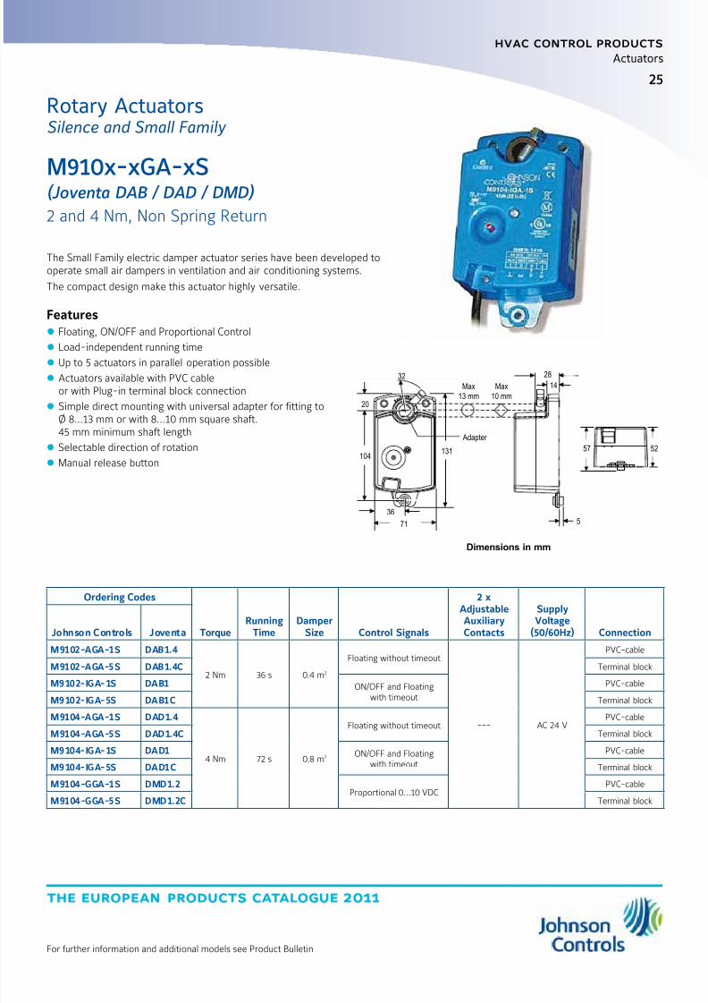
The Small Family electric damper actuator series have been developed tooperate small air dampers in ventilation and air conditioning systems.
The compact design make this actuator highly versatile.
Features z Floating, ON/OFF and Proportional Control
z
Load-independent running time z Up to 5 actuators in parallel operation possible
z Actuators available with PVC cableor with Plug-in terminal block connection
z Simple direct mounting with universal adapter for fitting toØ 8...13 mm or with 8...10 mm square shaft.45 mm minimum shaft length
z Selectable direction of rotation
z Manual release button
M910x-xGA-xS(Joventa DAB / DAD / DMD)
2 and 4 Nm, Non Spring Return
Rotary ActuatorsSilence and Small Family
Ordering Codes
TorqueRunning
TimeDamper
Size Control Signals
2 xAdjustableAuxiliaryContacts
SupplyVoltage
(50/60Hz) ConnectionJohnson Controls Joventa
M9102-AGA-1S DAB1.4
2 Nm 36 s 0.4 m2
Floating without timeout
--- AC 24 V
PVC-cable
M9102-AGA-5S DAB1.4C Terminal block
M9102-IGA-1S DAB1 ON/OFF and Floatingwith timeout
PVC-cable
M9102-IGA-5S DAB1C Terminal blockM9104-AGA-1S DAD1.4
4 Nm 72 s 0.8 m2
Floating without timeoutPVC-cable
M9104-AGA-5S DAD1.4C Terminal block
M9104-IGA-1S DAD1 ON/OFF and Floatingwith timeout
PVC-cable
M9104-IGA-5S DAD1C Terminal block
M9104-GGA-1S DMD1.2Proportional 0...10 VDC
PVC-cable
M9104-GGA-5S DMD1.2C Terminal block
20
104
71
131
28
14
5
57 52
Adapter
Max
13 mm
Max
10 mm
36
32
Dimensions in mm
8/6/2019 Publ-6576 Prod Cat 11
http://slidepdf.com/reader/full/publ-6576-prod-cat-11 34/298
the european products catalogue 2011
hvac control products
Actuators
26
For further information and additional models see Product Bulletin
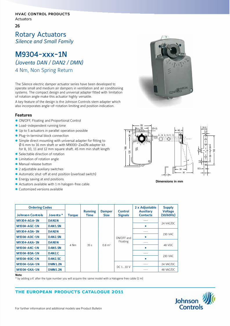
M9304-xxx-1N(Joventa DAN / DAN2 / DMN)
4 Nm, Non Spring Return
The Silence electric damper actuator series have been developed tooperate small and medium air dampers in ventilation and air conditioningsystems. The compact design and universal adapter fitted with limitationof rotation angle make this actuator highly versatile.
A key feature of the design is the Johnson Controls stem adapter whichalso incorporates angle-of-rotation limiting and position indication.
Features z ON/OFF, Floating and Proportional Control
z Load-independent running time
z Up to 5 actuators in parallel operation possible
z Plug-in terminal block connection
z Simple direct mounting with universal adapter for fitting toØ 6 mm to 16 mm shaft or with M9000-ZxxDN adapter kitfor 8, 10, 11 and 12 mm square shaft. 45 mm min shaft length
z Selectable direction of rotation
z Limitation of rotation angle
z Manual release button
z 2 adjustable auxiliary switches
z Automatic shut-off at end position (overload switch)
z Energy saving at end positions
z Actuators available with 1 m halogen-free cable
z Customized versions available
Ordering Codes
TorqueRunning
TimeDamper
SizeControlSignals
2 x AdjustableAuxiliaryContacts
SupplyVoltage
(50/60Hz)Johnson Controls Joventa *
M9304-AGA-1N DAN1N
4 Nm 35 s 0.8 m2
ON/OFF andFloating
---24 VAC/DC
M9304-AGC-1N DAN1.SN
M9304-ADA-1N DAN2N ---230 VAC
M9304-ADC-1N DAN2.SN
M9304-AKA-1N DAN5N ---48 VDC
M9304-AKC-1N DAN5.SN
M9304-BDA-1N DAN2.C ---230 VAC
M9304-BDC-1N DAN2.SC
M9304-GGA-1N DMN1.2NDC 1...10 V
--- 24 VAC/DC
M9304-GKA-1N DMN5.2N --- 48 VAC/DC
Note* by adding a K after the type number you will acquire the same model with a Halogene free cable (1 m)
9 0
6 0 3 0
0
Ø 4.5
12.66...16 8, 10, 11, 12
5585
1 6 6
1 2 0
3 6
4425.5
3.5
90
11
65
1 5 0
5 9
3 4
6
3 .
5
8.5
17
Dimensions in mm
Rotary ActuatorsSilence and Small Family

8/6/2019 Publ-6576 Prod Cat 11
http://slidepdf.com/reader/full/publ-6576-prod-cat-11 35/298
27
the european products catalogue 2011
hvac control products
Actuators
For further information and additional models see Product Bulletin
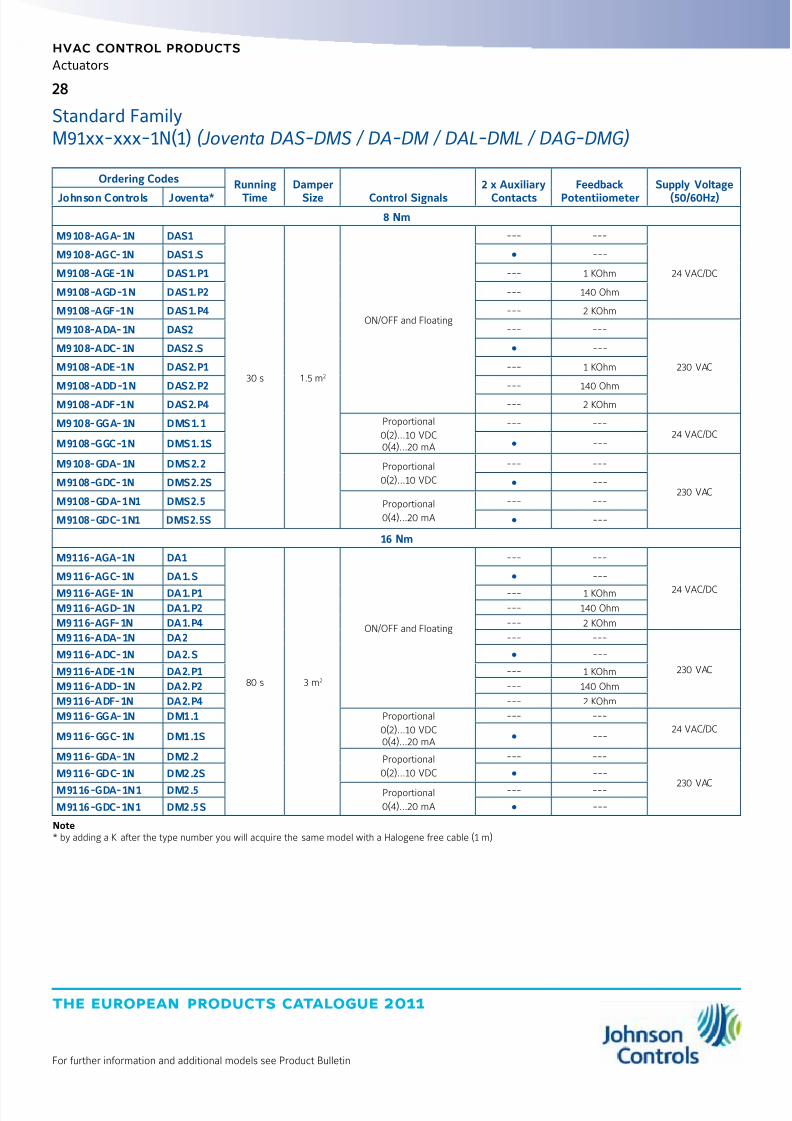
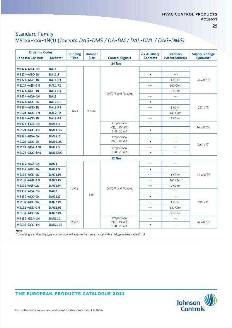
M91xx-xxx-1N(1)(Joventa DAS-DMS / DA-DM / DAL-DML / DAG-DMG)
8, 16, 24 and 32 Nm, Non Spring Return
The Standard electric actuators have been specially designed for usewith small and medium-sized air dampers and for terminal control unitsin air volume control systems.
Thanks to their very small size and clever construction they are also idealfor applications where space is limited.
A key feature of the design is the special Johnson Controls spindleadapter which also incorporates angle-of-rotation limiting
and position indication.
Features z ON/OFF, Floating and Proportional Control
z Load independent running time
z Paralleling of up to 5 actuators possible
z Screw terminal connections
z Universal adapter for:round spindles from 10 to 20 mm dia. orSquare spindles 10 ...16 mm with min. 48 mm ax length
z Choice of rotation
z Angle-of-rotation limiting
z Manual control by pushbutton
z 2 auxiliary switches
z Automatic end stops
z Power saving at end stops
z Customising available
z IP54
10045
25.5
3510-20
44
6
3.5
8.5
17
10-16
180 137
67.5
94.5
19034
73.25
8459
90
11
20
82.5
Dimensions in mm
Rotary ActuatorsStandard Family
8/6/2019 Publ-6576 Prod Cat 11
http://slidepdf.com/reader/full/publ-6576-prod-cat-11 36/298
the european products catalogue 2011
hvac control products
Actuators
28
For further information and additional models see Product Bulletin
Ordering Codes Running
Time
Damper
Size Control Signals
2 x Auxiliary
Contacts
Feedback
Potentiiometer
Supply Voltage
(50/60Hz)Johnson Controls Joventa*8 Nm
M9108-AGA-1N DAS1
30 s 1.5 m2
ON/OFF and Floating
--- ---
24 VAC/DC
M9108-AGC-1N DAS1.S ---
M9108-AGE-1N DAS1.P1 --- 1 KOhm
M9108-AGD-1N DAS1.P2 --- 140 Ohm
M9108-AGF-1N DAS1.P4 --- 2 KOhm
M9108-ADA-1N DAS2 --- ---
230 VAC
M9108-ADC-1N DAS2.S ---
M9108-ADE-1N DAS2.P1 --- 1 KOhm
M9108-ADD-1N DAS2.P2 --- 140 Ohm
M9108-ADF-1N DAS2.P4 --- 2 KOhm
M9108-GGA-1N DMS1.1 Proportional
0(2)...10 VDC0(4)...20 mA
--- ---24 VAC/DC
M9108-GGC-1N DMS1.1S ---
M9108-GDA-1N DMS2.2 Proportional
0(2)...10 VDC
--- ---
230 VACM9108-GDC-1N DMS2.2S ---
M9108-GDA-1N1 DMS2.5 Proportional
0(4)...20 mA
--- ---
M9108-GDC-1N1 DMS2.5S ---
16 Nm
M9116-AGA-1N DA1
80 s 3 m2
ON/OFF and Floating
--- ---
24 VAC/DC
M9116-AGC-1N DA1.S ---
M9116-AGE-1N DA1.P1 --- 1 KOhm
M9116-AGD-1N DA1.P2 --- 140 Ohm
M9116-AGF-1N DA1.P4 --- 2 KOhm
M9116-ADA-1N DA2 --- ---
230 VAC
M9116-ADC-1N DA2.S ---
M9116-ADE-1N DA2.P1 --- 1 KOhm
M9116-ADD-1N DA2.P2 --- 140 Ohm
M9116-ADF-1N DA2.P4 --- 2 KOhm
M9116-GGA-1N DM1.1 Proportional
0(2)...10 VDC0(4)...20 mA
--- ---24 VAC/DC
M9116-GGC-1N DM1.1S ---
M9116-GDA-1N DM2.2 Proportional
0(2)...10 VDC
--- ---
230 VAC
M9116-GDC-1N DM2.2S ---
M9116-GDA-1N1 DM2.5 Proportional
0(4)...20 mA
--- ---
M9116-GDC-1N1 DM2.5S ---
Note* by adding a K after the type number you will acquire the same model with a Halogene free cable (1 m)
Standard FamilyM91xx-xxx-1N(1) (Joventa DAS-DMS / DA-DM / DAL-DML / DAG-DMG)
8/6/2019 Publ-6576 Prod Cat 11
http://slidepdf.com/reader/full/publ-6576-prod-cat-11 37/298
29
the european products catalogue 2011
hvac control products
Actuators
For further information and additional models see Product Bulletin
Ordering Codes Running
Time
Damper
Size Control Signals
2 x Auxiliary
Contacts
Feedback
Potentiiometer
Supply Voltage
(50/60Hz)Johnson Controls Joventa*24 Nm
M9124-AGA-1N DAL1
125 s 4.5 m2
ON/OFF and Floating
--- ---
24 VAC/DC
M9124-AGC-1N DAL1.S ---
M9124-AGE-1N DAL1.P1 --- 1 KOhm
M9124-AGD-1N DAL1.P2 --- 140 Ohm
M9124-AGF-1N DAL1.P4 --- 2 KOhm
M9124-ADA-1N DAL2 --- ---
230 VAC
M9124-ADC-1N DAL2.S ---
M9124-ADE-1N DAL2.P1 --- 1 KOhm
M9124-ADD-1N DAL2.P2 --- 140 Ohm
M9124-ADF-1N DAL2.P4 --- 2 KOhm
M9124-GGA-1N DML1.1 Proportional
0(2)...10 VDC
0(4)...20 mA
--- ---24 VAC/DC
M9124-GGC-1N DML1.1S ---
M9124-GDA-1N DML2.2 Proportional
0(2)...10 VDC
--- ---
230 VACM9124-GDC-1N DML2.2S ---
M9124-GDA-1N1 DML2.5 Proportional
0(4)...20 mA
--- ---
M9124-GDC-1N1 DML2.5S ---
32 Nm
M9132-AGA-1N DAG1
140 s
6 m2
ON/OFF and Floating
--- ---
24 VAC/DC
M9132-AGC-1N DAG1.S ---
M9132-AGE-1N DAG1.P1 --- 1 KOhm
M9132-AGD-1N DAG1.P2 --- 140 Ohm
M9132-AGF-1N DAG1.P4 --- 2 KOhm
M9132-ADA-1N DAG2 --- ---
230 VAC
M9132-ADC-1N DAG2.S ---
M9132-ADE-1N DAG2.P1 --- 1 KOhm
M9132-ADD-1N DAG2.P2 --- 140 Ohm
M9132-ADF-1N DAG2.P4 --- 2 KOhm
M9132-GGA-1N DMG1.1200 s
Proportional
0(2)...10 VDC
0(4)...20 mA
--- ---24 VAC/DC
M9132-GGC-1N DMG1.1S ---
Note* by adding a K after the type number you will acquire the same model with a Halogene free cable (1 m)
Standard FamilyM91xx-xxx-1N(1) (Joventa DAS-DMS / DA-DM / DAL-DML / DAG-DMG)
8/6/2019 Publ-6576 Prod Cat 11
http://slidepdf.com/reader/full/publ-6576-prod-cat-11 38/298
the european products catalogue 2011
hvac control products
Actuators
30
For further information and additional models see Product Bulletin
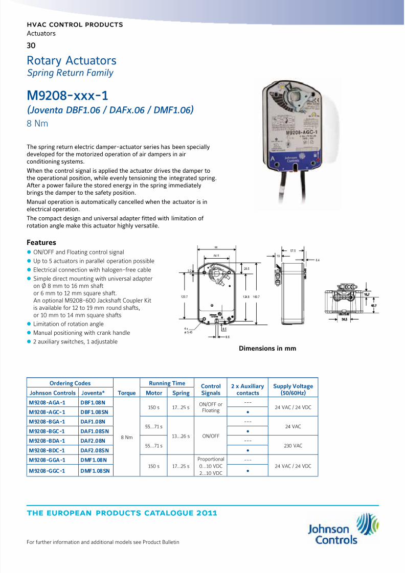
M9208-xxx-1(Joventa DBF1.06 / DAFx.06 / DMF1.06)
8 Nm
The spring return electric damper-actuator series has been speciallydeveloped for the motorized operation of air dampers in airconditioning systems.
When the control signal is applied the actuator drives the damper tothe operational position, while evenly tensioning the integrated spring.After a power failure the stored energy in the spring immediatelybrings the damper to the safety position.
Manual operation is automatically cancelled when the actuator is inelectrical operation.
The compact design and universal adapter fitted with limitation of rotation angle make this actuator highly versatile.
Features z ON/OFF and Floating control signal
z Up to 5 actuators in parallel operation possible
z Electrical connection with halogen-free cable
z Simple direct mounting with universal adapteron Ø 8 mm to 16 mm shaftor 6 mm to 12 mm square shaft.
An optional M9208-600 Jackshaft Coupler Kitis available for 12 to 19 mm round shafts,or 10 mm to 14 mm square shafts
z Limitation of rotation angle
z Manual positioning with crank handle
z 2 auxiliary switches, 1 adjustable
Rotary ActuatorsSpring Return Family
64.5
3.2
120.7
4 x
5.45ø
28.5
99
1 24 .8 1 60 .716.7
40.7
34.5
6.4
19
57.5
Dimensions in mm
Ordering Codes
Torque
Running Time ControlSignals
2 x Auxiliarycontacts
Supply Voltage(50/60Hz)Johnson Controls Joventa* Motor Spring
M9208-AGA-1 DBF1.08N
8 Nm
150 s 17...25 sON/OFF or
Floating---
24 VAC / 24 VDCM9208-AGC-1 DBF1.08SN
M9208-BGA-1 DAF1.08N55...71 s
13...26 s ON/OFF
---24 VAC
M9208-BGC-1 DAF1.08SN
M9208-BDA-1 DAF2.08N55...71 s
---230 VAC
M9208-BDC-1 DAF2.08SN
M9208-GGA-1 DMF1.08N150 s 17...25 s
Proportional
0...10 VDC
2...10 VDC
---24 VAC / 24 VDC
M9208-GGC-1 DMF1.08SN
8/6/2019 Publ-6576 Prod Cat 11
http://slidepdf.com/reader/full/publ-6576-prod-cat-11 39/298
31
the european products catalogue 2011
hvac control products
Actuators
For further information and additional models see Product Bulletin
Accessories and Replacement Parts (Order Separately)
Ordering Codes DescriptionsM9000-604 Replacement Anti-Rotation Bracket Kit for M9208, M9210 and M9220 Series Electric Spring Return Actuators (quantity 1)
M9208-100 Remote Mounting Kit, including Mounting Bracket, M9208-150 Crankarm, Ball Joint and mounting fastener (quantity 1)
M9208-150 Crankarm (quantity 1)
M9208-600Large Shaft Coupler Kit (with Locking Clip) for Mounting M9208-xxx-1 Series Electric Spring Return Actuators on dampers with roundshafts from 12 to 19 mm or square shafts from 10 to 14 mm (quantity 1)
M9208-601Replacement Standard Coupler Kit (with Locking Clip) for mounting M9208-xxx-1 Series Electric Spring Return Actuators on dampers withround shafts from 8 to 16 mm or square shafts from 6 to 12 mm (quantity 1)
M9208-602 Replacement Locking Clips for M9208-xxx-1 Series Electric Spring Return Actuators (quantity 5)
M9208-603 Adjustable Stop Kit for M9208-xxx-1 Series Electric Spring Return Actuators (quantity 1)
M9208-604 Replacement Manual Override Cranks for M9208 Series Electric Spring Return Actuators with long crank radius: 72 mm (quantity 5)
M9208-605 Replacement Manual Override Cranks for M9208 Series Electric Spring Return Actuators with short crank radius: 46.5 mm (quantity 5)
Spring Return FamilyM9208-xxx-1 (Joventa DBF1.06 / DAFx.06 / DMF1.06)

8/6/2019 Publ-6576 Prod Cat 11
http://slidepdf.com/reader/full/publ-6576-prod-cat-11 40/298
the european products catalogue 2011
hvac control products
Actuators
32
For further information and additional models see Product Bulletin
M92x0-xxx-1(Joventa DAFx.10 / DBF1.10 / DMF1.10)
10, 20 Nm
The M9210 and M9220 Series Actuators are direct mount, spring returnelectric that provide reliable control of dampers and valves in Heating,Ventilating, and Air Conditioning (HVAC) systems.
The Actuators are available for use with on/off, floating, and proportionalcontrollers. These bidirectional actuators do not require a damperlinkage, and are easily installed on dampers.
Features z ON/OFF, Floating and Proportional Control
z Two or three models mounted in tandem deliver twiceor triple the torque
z Up to 5 actuators in parallel operation possible
z Optional adjustable end stops.The Optional Adjustable End Stops are used to shortenthe actuator stroke electronic stall detection throughout entirerotation range that extends the life of the actuator by deactivatingthe actuator motor when an overload condition is detected
z Integrated cables halogen-free cables
z IP54 (NEMA2)
z Rated Aluminium Enclosure z Easy-to-Use Locking manual overridewith auto release and crank storage
z Energy saving at end position
z Two Integral gold Auxiliary switches (xxC Models)
Ordering Codes
Torque
Running Time DamperSize Control Signals
2 x Auxiliarycontacts
Supply Voltage(50/60Hz)Johnson Controls Joventa* Motor Spring
10 Nm
M9210-AGA-1 DBF1.10
10 Nm
150 s 20 s
2.0 m2
ON/OFF and Floating---
AC/DC 24 VM9210-AGC-1 DBF1.10S
M9210-BDA-1 DAF2.10
25...57 s 11...15 s ON/OFF
---230 VAC
M9210-BDC-1 DAF2.10S
M9210-BGA-1 DAF1.10 ---
AC/DC 24 V
M9210-BGC-1 DAF1.10S
M9210-GGA-1 DMF1.10
150 s 26 s
Proportional
0(2)...10 VDC
---
M9210-GGC-1 DMF1.10S
M9210-HGA-1 DHF1.10 Proportional
0(2)...10 VDCwith Span offset
---
M9210-HGC-1 DHF1.10S
Note* : by adding a K after the type number you will acquire the same model with a Halogene free cable (1 m)
900
A
44
381
19
5625
254
56
27
10-20 10-16
102
51
40
262
40
176
6.5
40
Dimensions in mm
Rotary ActuatorsSpring Return Family

8/6/2019 Publ-6576 Prod Cat 11
http://slidepdf.com/reader/full/publ-6576-prod-cat-11 41/298
33
the european products catalogue 2011
hvac control products
Actuators
For further information and additional models see Product Bulletin
Spring Return FamilyM92x0-xxx-1 (Joventa DAFx.10 / DBF1.10 / DMF1.10)
Accessories and Replacement Parts (Order Separately)
Ordering Codes Description
DMPR-KC003* 178 mm Blade Pin Extension (without Bracket) for Johnson Controls® Direct Mount Damper Applications
M9000-158 Tandem Mounting Kit used to Mount Two Models of M9220-xxx-3 Series Proportional Electric Spring Return Actuators
M9000-153 Crank arm
M9000-170 Remote Mounting Kit, Horizontal. Kit includes Mounting Bracket, M9000-153 Crank Arm, Ball Joint and Mounting Bolts
M9000-171 Remote Mounting Kit, Vertical. Kit includes Mounting Bracket, M9000-153 Crank Arm, Ball Joint and Mounting Bolts
M9000-200 Commissioning Tool that Provides a Control Signal to Drive 24 V Floating, Floating, Proportional and/or Resistive Electric Actuators
M9000-604 Replacement Anti-rotation Bracket Kit (with Screws) for M9220-xxx-3 Series Proportional Electric Spring Return Actuators
M9220-60025 mm Jackshaft Coupler Kit (with Locking Clip) for Mounting M9220-xxx-3 Series Proportional Electric Spring Return Actuators onDampers with 19 to 27 mm Round Shafts, or 16, 18 and 19 mm Square Shafts
M9220-601Replacement Coupler Kit (with Locking Clip) for Mounting M9220-xxx-3 Series Proportional Electric Spring Return Actuators on Damperwith 12 to 19 mm Round Shafts, or 10, 12 and 14 mm Square Shafts
M9220-602 Replacement Locking Clips for M9220-xxx-3 Series Proportional Electric Spring Return Actuators (FiveperBag)
M9220-603 Adjustable Stop Kit for M9220-xxx-3 Series Proportional Electric Spring Return Actuators
M9220-604 Replacement Manual Override Cranks for M9220-xxx-3 Series Proportional Electric Spring Return Actuators (Five per Bag)
M9220-610 Replacement Shaft Gripper, 10 mm Square Shaft with Locking Clip
M9220-612 Replacement Shaft Gripper, 12 mm Square Shaft with Locking Clip
M9220-614 Replacement Shaft Gripper, 14 mm Square Shaft with Locking Clip
Note* : Furnished with the damper and may be ordered separately.
Ordering Codes
Torque
Running Time Damper
Size Control Signals
2 x Auxiliary
contacts
Supply Voltage
(50/60Hz)Johnson Controls Joventa* Motor Spring20 Nm
M9220-AGA-1 DBF1.20
20 Nm
150 s 20 s 2.0 m2 ON/OFF and Floating---
AC/DC 24 VM9220-AGC-1 DBF1.20S
M9220-BDA-1 DAF2.20
25...57 s 11...15 s
4.0 m2
ON/OFF
---230 VAC
M9220-BDC-1 DAF2.20S
M9220-BGA-1 DAF1.20 ---
AC/DC 24 V
M9220-BGC-1 DAF1.20S
M9220-GGA-1 DMF1.20
150 s 26 s
Proportional
0(2)...10 VDC
---
M9220-GGC-1 DMF1.20S
M9220-HGA-1 DHF1.20 Proportional
0(2)...10 VDCwith Span offset
---
M9220-HGC-1 DHF1.20S
Note* : by adding a K after the type number you will acquire the same model with a Halogene free cable (1 m)
8/6/2019 Publ-6576 Prod Cat 11
http://slidepdf.com/reader/full/publ-6576-prod-cat-11 42/298
the european products catalogue 2011
hvac control products
Actuators
34
For further information and additional models see Product Bulletin
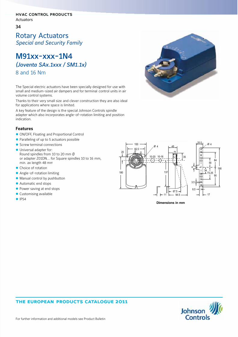
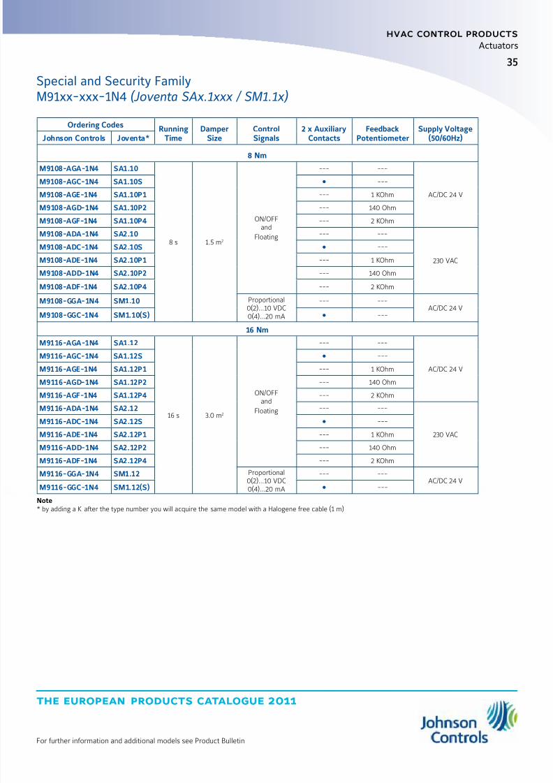
M91xx-xxx-1N4(Joventa SAx.1xxx / SM1.1x)
8 and 16 Nm
The Special electric actuators have been specially designed for use withsmall and medium-sized air dampers and for terminal control units in airvolume control systems.
Thanks to their very small size and clever construction they are also idealfor applications where space is limited.
A key feature of the design is the special Johnson Controls spindleadapter which also incorporates angle-of-rotation limiting and position
indication.
Features z ON/OFF, Floating and Proportional Control
z Paralleling of up to 5 actuators possible
z Screw terminal connections
z Universal adapter for:Round spindles from 10 to 20 mm Øor adapter Z01DN... for Square spindles 10 to 16 mm,min. ax length 48 mm
z Choice of rotation
z Angle-of-rotation limiting
z Manual control by pushbuttonz Automatic end stops
z Power saving at end stops
z Customising available
z IP54
10045
25.5
3510-20
44
6
3.5
8.5
17
10-16
180 137
67.5
94.5
19034
73.25
84
59
90
11
20
82.5
Dimensions in mm
Rotary ActuatorsSpecial and Security Family
8/6/2019 Publ-6576 Prod Cat 11
http://slidepdf.com/reader/full/publ-6576-prod-cat-11 43/298
35
the european products catalogue 2011
hvac control products
Actuators
For further information and additional models see Product Bulletin
Special and Security FamilyM91xx-xxx-1N4 (Joventa SAx.1xxx / SM1.1x)
Ordering Codes Running
Time
Damper
Size
Control
Signals
2 x Auxiliary
Contacts
Feedback
Potentiometer
Supply Voltage
(50/60Hz)Johnson Controls Joventa*
8 Nm
M9108-AGA-1N4 SA1.10
8 s 1.5 m2
ON/OFFand
Floating
--- ---
AC/DC 24 V
M9108-AGC-1N4 SA1.10S ---
M9108-AGE-1N4 SA1.10P1 --- 1 KOhm
M9108-AGD-1N4 SA1.10P2 --- 140 Ohm
M9108-AGF-1N4 SA1.10P4 --- 2 KOhm
M9108-ADA-1N4 SA2.10 --- ---
230 VAC
M9108-ADC-1N4 SA2.10S ---
M9108-ADE-1N4 SA2.10P1 --- 1 KOhm
M9108-ADD-1N4 SA2.10P2 --- 140 OhmM9108-ADF-1N4 SA2.10P4 --- 2 KOhm
M9108-GGA-1N4 SM1.10 Proportional0(2)...10 VDC0(4)...20 mA
--- ---AC/DC 24 V
M9108-GGC-1N4 SM1.10(S) ---
16 Nm
M9116-AGA-1N4 SA1.12
16 s 3.0 m2
ON/OFFand
Floating
--- ---
AC/DC 24 V
M9116-AGC-1N4 SA1.12S ---
M9116-AGE-1N4 SA1.12P1 --- 1 KOhm
M9116-AGD-1N4 SA1.12P2 --- 140 Ohm
M9116-AGF-1N4 SA1.12P4 --- 2 KOhm
M9116-ADA-1N4 SA2.12 --- ---
230 VAC
M9116-ADC-1N4 SA2.12S ---
M9116-ADE-1N4 SA2.12P1 --- 1 KOhm
M9116-ADD-1N4 SA2.12P2 --- 140 Ohm
M9116-ADF-1N4 SA2.12P4 --- 2 KOhm
M9116-GGA-1N4 SM1.12 Proportional0(2)...10 VDC0(4)...20 mA
--- ---AC/DC 24 V
M9116-GGC-1N4 SM1.12(S) ---
Note* by adding a K after the type number you will acquire the same model with a Halogene free cable (1 m)
8/6/2019 Publ-6576 Prod Cat 11
http://slidepdf.com/reader/full/publ-6576-prod-cat-11 44/298
the european products catalogue 2011
hvac control products
Actuators
36
For further information and additional models see Product Bulletin
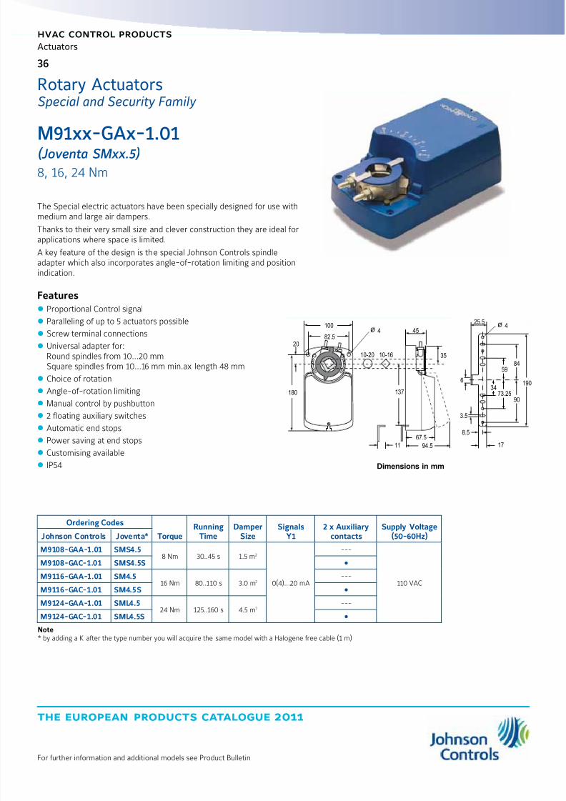
M91xx-GAx-1.01(Joventa SMxx.5)
8, 16, 24 Nm
The Special electric actuators have been specially designed for use withmedium and large air dampers.
Thanks to their very small size and clever construction they are ideal forapplications where space is limited.
A key feature of the design is the special Johnson Controls spindleadapter which also incorporates angle-of-rotation limiting and positionindication.
Features z Proportional Control signal
z Paralleling of up to 5 actuators possible
z Screw terminal connections
z Universal adapter for:Round spindles from 10...20 mmSquare spindles from 10...16 mm min.ax length 48 mm
z Choice of rotation
z Angle-of-rotation limiting
z Manual control by pushbutton
z 2 floating auxiliary switches
z Automatic end stops
z Power saving at end stops
z Customising available
z IP54
Ordering Codes
TorqueRunning
TimeDamper
SizeSignals
Y12 x Auxiliary
contactsSupply Voltage
(50-60Hz)Johnson Controls Joventa*
M9108-GAA-1.01 SMS4.58 Nm 30..45 s 1.5 m2
0(4)…20 mA
---
110 VAC
M9108-GAC-1.01 SMS4.5S
M9116-GAA-1.01 SM4.516 Nm 80..110 s 3.0 m2
---
M9116-GAC-1.01 SM4.5S
M9124-GAA-1.01 SML4.524 Nm 125..160 s 4.5 m2
---
M9124-GAC-1.01 SML4.5S
Note* by adding a K after the type number you will acquire the same model with a Halogene free cable (1 m)
10045
25.5
3510-20
44
6
3.5
8.5
17
10-16
180 137
67.5
94.5
19034
73.25
8459
90
11
20
82.5
Dimensions in mm
Rotary ActuatorsSpecial and Security Family
8/6/2019 Publ-6576 Prod Cat 11
http://slidepdf.com/reader/full/publ-6576-prod-cat-11 45/298
37
the european products catalogue 2011
hvac control products
Actuators
For further information and additional models see Product Bulletin
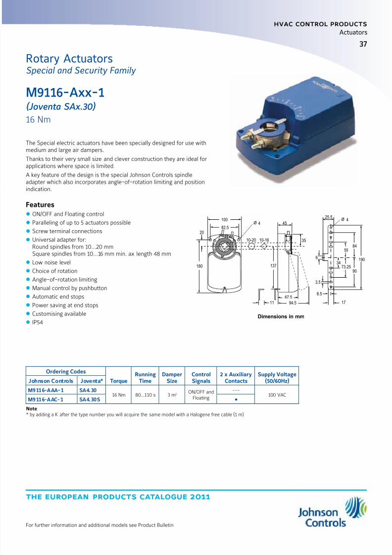
The Special electric actuators have been specially designed for use withmedium and large air dampers.
Thanks to their very small size and clever construction they are ideal forapplications where space is limited.
A key feature of the design is the special Johnson Controls spindleadapter which also incorporates angle-of-rotation limiting and positionindication.
Features z ON/OFF and Floating control
z Paralleling of up to 5 actuators possible
z Screw terminal connections
z Universal adapter for:Round spindles from 10...20 mmSquare spindles from 10...16 mm min. ax length 48 mm
z Low noise level
z Choice of rotation
z Angle-of-rotation limiting
z Manual control by pushbutton
z Automatic end stops
z Power saving at end stops
z Customising available
z IP54
Ordering Codes
TorqueRunning
TimeDamper
SizeControlSignals
2 x AuxiliaryContacts
Supply Voltage(50/60Hz)Johnson Controls Joventa*
M9116-AAA-1 SA4.3016 Nm 80...110 s 3 m2 ON/OFF and
Floating---
100 VACM9116-AAC-1 SA4.30S
Note* by adding a K after the type number you will acquire the same model with a Halogene free cable (1 m)
10045
25.5
3510-20
44
6
3.5
8.5
17
10-16
180 137
67.5
94.5
19034
73.25
8459
90
11
20
82.5
Dimensions in mm
M9116-Axx-1(Joventa SAx.30)
16 Nm
Rotary ActuatorsSpecial and Security Family
8/6/2019 Publ-6576 Prod Cat 11
http://slidepdf.com/reader/full/publ-6576-prod-cat-11 46/298
the european products catalogue 2011
hvac control products
Actuators
38
For further information and additional models see Product Bulletin
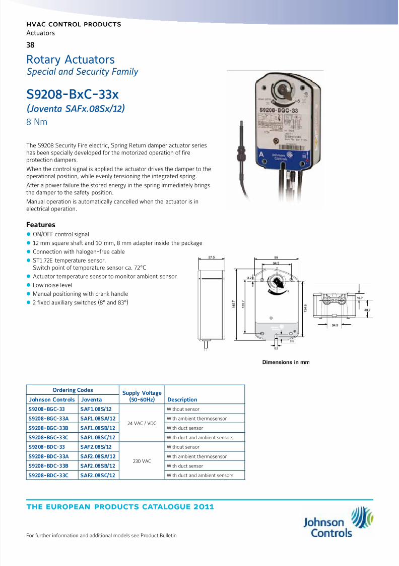
S9208-BxC-33x(Joventa SAFx.08Sx/12)
8 Nm
Rotary ActuatorsSpecial and Security Family
The S9208 Security Fire electric, Spring Return damper actuator serieshas been specially developed for the motorized operation of fireprotection dampers.
When the control signal is applied the actuator drives the damper to theoperational position, while evenly tensioning the integrated spring.
After a power failure the stored energy in the spring immediately bringsthe damper to the safety position.
Manual operation is automatically cancelled when the actuator is inelectrical operation.
Features z ON/OFF control signal
z 12 mm square shaft and 10 mm, 8 mm adapter inside the package
z Connection with halogen-free cable
z ST1.72E temperature sensor.Switch point of temperature sensor ca. 72°C
z Actuator temperature sensor to monitor ambient sensor.
z Low noise level
z Manual positioning with crank handle
z 2 fixed auxiliary switches (8° and 83°)
Dimensions in mm
Ordering Codes Supply Voltage(50-60Hz) DescriptionJohnson Controls Joventa
S9208-BGC-33 SAF1.08S/12
24 VAC / VDC
Without sensor
S9208-BGC-33A SAF1.08SA/12 With ambient thermosensor
S9208-BGC-33B SAF1.08SB/12 With duct sensor
S9208-BGC-33C SAF1.08SC/12 With duct and ambient sensors
S9208-BDC-33 SAF2.08S/12
230 VAC
Without sensor
S9208-BDC-33A SAF2.08SA/12 With ambient thermosensor
S9208-BDC-33B SAF2.08SB/12 With duct sensor
S9208-BDC-33C SAF2.08SC/12 With duct and ambient sensors

8/6/2019 Publ-6576 Prod Cat 11
http://slidepdf.com/reader/full/publ-6576-prod-cat-11 47/298
39
the european products catalogue 2011
hvac control products
Actuators
For further information and additional models see Product Bulletin
S92x0-BxC-3xx(Joventa SAFx.10 / SAFx.20)
10, 20 Nm
The S9210 and S9220 Security Fire electric, spring return damper-actuatorseries has been specially developed for the motorized operation of safetydampers e.g. fire protection dampers. When the control signal is appliedthe actuator drives the damper to the operational position, while evenlytensioning the integrated spring. After a power failure the stored energy inthe spring immediately brings the damper to the safety position.
Features z ON/OFF Control
z 10/11/12/14 mm steel adapter for square shaft
z Ambient temperature sensor and direct connectionof duct temperature sensor
z Low noise level
z Energy saving at end position
z Integrated cables halogen-free cables
z IP54 (NEMA2)
z Rated Aluminium Enclosure
z Easy-to-Use Locking manual overridewith auto release and crank storage
z Energy saving at end position
z Two Integral gold Auxiliary switches (xxC Models)
Accessories and Replacement Parts (Order Separately)
Ordering Codes Description
DMPR-KC003* 178 mm Blade Pin Extension (without Bracket) for Johnson Controls® Direct Mount Damper Applications
M9000-158 Tandem Mounting Kit used to Mount Two Models of M9220-xxx-3 Series Proportional Electric Spring Return Actuators
M9000-153 Crank arm
M9000-170 Remote Mounting Kit, Horizontal. Kit includes Mounting Bracket, M9000-153 Crank Arm, Ball Joint and Mounting Bolts
M9000-171 Remote Mounting Kit, Vertical. Kit includes Mounting Bracket, M9000-153 Crank Arm, Ball Joint and Mounting Bolts
M9000-200 Commissioning Tool that Provides a Control Signal to Drive 24 V Floating, Floating, Proportional and/or Resistive Electric Actuators
M9000-604 Replacement Anti-rotation Bracket Kit (with Screws) for M9220-xxx-3 Series Proportional Electric Spring Return Actuators
M9220-60025 mm Jackshaft Coupler Kit (with Locking Clip) for Mounting M9220-xxx-3 Series Proportional Electric Spring Return Actuators onDampers with 19 to 27 mm Round Shafts, or 16, 18 and 19 mm Square Shafts
M9220-601Replacement Coupler Kit (with Locking Clip) for Mounting M9220-xxx-3 Series Proportional Electric Spring Return Actuators on Damperwith 12 to 19 mm Round Shafts, or 10, 12 and 14 mm Square Shafts
M9220-602 Replacement Locking Clips for M9220-xxx-3 Series Proportional Electric Spring Return Actuators (FiveperBag)
M9220-603 Adjustable Stop Kit for M9220-xxx-3 Series Proportional Electric Spring Return Actuators
M9220-604 Replacement Manual Override Cranks for M9220-xxx-3 Series Proportional Electric Spring Return Actuators (Five per Bag)
M9220-610 Replacement Shaft Gripper, 10 mm Square Shaft with Locking Clip
M9220-612 Replacement Shaft Gripper, 12 mm Square Shaft with Locking Clip
M9220-614 Replacement Shaft Gripper, 14 mm Square Shaft with Locking Clip
Note * Furnished with the damper and may be ordered separately.
44
81
19
5625
254
56 10/11/12/14 mm
27
102
51
40
262
40
176
6.5
40
Dimensions in mm
Rotary ActuatorsSpecial and Security Family

8/6/2019 Publ-6576 Prod Cat 11
http://slidepdf.com/reader/full/publ-6576-prod-cat-11 48/298
the european products catalogue 2011
hvac control products
Actuators
40
For further information and additional models see Product Bulletin
Ordering Codes Power
Supply
Squareshaft
Adapter SensorJohnson Controls Joventa10 Nm
S9210-BDC-31 SAF2.10S/10
AC 230 V
10 mm
---
S9210-BDC-31A SAF2.10SA/10 Ambient Sensor
S9210-BDC-31B SAF2.10SB/10 Duct Sensor
S9210-BDC-31C SAF2.10SC/10 Ambient and Duct Sensor
S9210-BDC-32 SAF2.10S/11
11 mm
---
S9210-BDC-32A SAF2.10SA/11 Ambient Sensor
S9210-BDC-32B SAF2.10SB/11 Duct Sensor
S9210-BDC-32C SAF2.10SC/11 Ambient and Duct Sensor
S9210-BDC-33 SAF2.10S/12
12 mm
---
S9210-BDC-33A SAF2.10SA/12 Ambient Sensor
S9210-BDC-33B SAF2.10SB/12 Duct Sensor
S9210-BDC-33C SAF2.10SC/12 Ambient and Duct Sensor
S9210-BDC-34 SAF2.10S/14
14 mm
---
S9210-BDC-34A SAF2.10SA/14 Ambient Sensor
S9210-BDC-34B SAF2.10SB/14 Duct Sensor
S9210-BDC-34C SAF2.10SC/14 Ambient and Duct Sensor
S9210-BGC-31 SAF1.10S/10
AC/DC 24 V
10 mm
---
S9210-BGC-31A SAF1.10SA/10 Ambient Sensor
S9210-BGC-31B SAF1.10SB/10 Duct Sensor
S9210-BGC-31C SAF1.10SC/10 Ambient and Duct Sensor
S9210-BGC-32 SAF1.10S/11
11 mm
---
S9210-BGC-32A SAF1.10SA/11 Ambient Sensor
S9210-BGC-32B SAF1.10SB/11 Duct Sensor
S9210-BGC-32C SAF1.10SC/11 Ambient and Duct Sensor
S9210-BGC-33 SAF1.10S/12
12 mm
---
S9210-BGC-33A SAF1.10SA/12 Ambient Sensor
S9210-BGC-33B SAF1.10SB/12 Duct Sensor
S9210-BGC-33C SAF1.10SC/12 Ambient and Duct Sensor
S9210-BGC-34 SAF1.10S/14
14 mm
---
S9210-BGC-34A SAF1.10SA/14 Ambient Sensor
S9210-BGC-34B SAF1.10SB/14 Duct Sensor
S9210-BGC-34C SAF1.10SC/14 Ambient and Duct Sensor
Special and Security FamilyS92x0-BxC-3xx (Joventa SAFx.10 / SAFx.20)

8/6/2019 Publ-6576 Prod Cat 11
http://slidepdf.com/reader/full/publ-6576-prod-cat-11 49/298
41
the european products catalogue 2011
hvac control products
Actuators
For further information and additional models see Product Bulletin
Ordering Codes Power
Supply
Squareshaft
Adapter SensorJohnson Controls JoventaS9220-BDC-31 SAF2.20S/10
AC 230 V
10 mm
---
S9220-BDC-31A SAF2.20SA/10 Ambient Sensor
S9220-BDC-31B SAF2.20SB/10 Duct Sensor
S9220-BDC-31C SAF2.20SC/10 Ambient and Duct Sensor
S9220-BDC-32 SAF2.20S/11
11 mm
---
S9220-BDC-32A SAF2.20SA/11 Ambient Sensor
S9220-BDC-32B SAF2.20SB/11 Duct Sensor
S9220-BDC-32C SAF2.20SC/11 Ambient and Duct Sensor
S9220-BDC-33 SAF2.20S/12
12 mm
---
S9220-BDC-33A SAF2.20SA/12 Ambient Sensor
S9220-BDC-33B SAF2.20SB/12 Duct Sensor
S9220-BDC-33C SAF2.20SC/12 Ambient and Duct Sensor
S9220-BDC-34 SAF2.20S/14
14 mm
---
S9220-BDC-34A SAF2.20SA/14 Ambient Sensor
S9220-BDC-34B SAF2.20SB/14 Duct Sensor
S9220-BDC-34C SAF2.20SC/14 Ambient and Duct Sensor
S9220-BGC-31 SAF1.20S/10
AC/DC 24 V
10 mm
---
S9220-BGC-31A SAF1.20SA/10 Ambient Sensor
S9220-BGC-31B SAF1.20SB/10 Duct Sensor
S9220-BGC-31C SAF1.20SC/10 Ambient and Duct Sensor
S9220-BGC-32 SAF1.20S/11
11 mm
---
S9220-BGC-32A SAF1.20SA/11 Ambient Sensor
S9220-BGC-32B SAF1.20SB/11 Duct Sensor
S9220-BGC-32C SAF1.20SC/11 Ambient and Duct Sensor
S9220-BGC-33 SAF1.20S/12
12 mm
---
S9220-BGC-33A SAF1.20SA/12 Ambient Sensor
S9220-BGC-33B SAF1.20SB/12 Duct Sensor
S9220-BGC-33C SAF1.20SC/12 Ambient and Duct Sensor
S9220-BGC-34 SAF1.20S/14
14 mm
---
S9220-BGC-34A SAF1.20SA/14 Ambient Sensor
S9220-BGC-34B SAF1.20SB/14 Duct Sensor
S9220-BGC-34C SAF1.20SC/14 Ambient and Duct Sensor
Special and Security FamilyS92x0-BxC-3xx (Joventa SAFx.10 / SAFx.20)
8/6/2019 Publ-6576 Prod Cat 11
http://slidepdf.com/reader/full/publ-6576-prod-cat-11 50/298
the european products catalogue 2011
hvac control products
Actuators
42
For further information and additional models see Product Bulletin
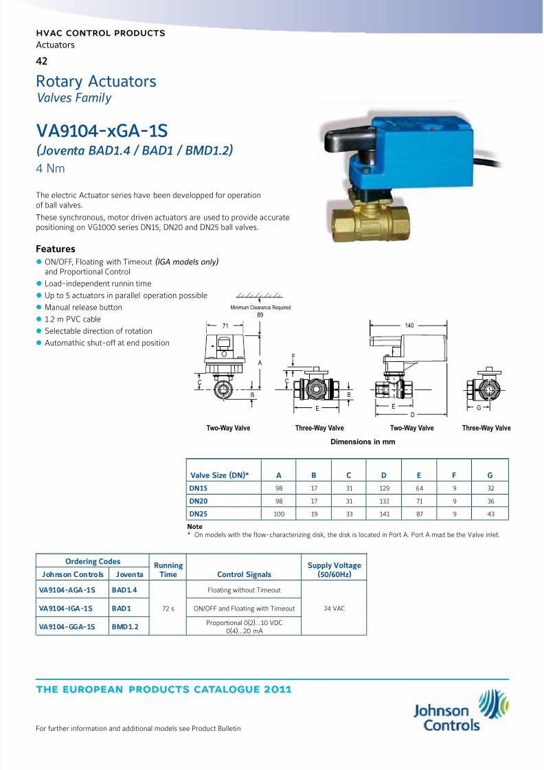
VA9104-xGA-1S(Joventa BAD1.4 / BAD1 / BMD1.2)
4 Nm
The electric Actuator series have been developped for operationof ball valves.
These synchronous, motor driven actuators are used to provide accuratepositioning on VG1000 series DN15, DN20 and DN25 ball valves.
Features z ON/OFF, Floating with Timeout (IGA models only)
and Proportional Control z Load-independent runnin time
z Up to 5 actuators in parallel operation possible
z Manual release button
z 1.2 m PVC cable
z Selectable direction of rotation
z Automathic shut-off at end position
Ordering Codes RunningTime Control Signals
Supply Voltage(50/60Hz)Johnson Controls Joventa
VA9104-AGA-1S BAD1.4
72 s
Floating without Timeout
24 VACVA9104-IGA-1S BAD1 ON/OFF and Floating with Timeout
VA9104-GGA-1S BMD1.2Proportional 0(2)...10 VDC
0(4)...20 mA
89
71
C
B
A
E
F
B
Minimum Clearance Required
Two-Way Valve Three-Way Valve Two-Way Valve Three-Way Valve
C
140
ED
G
Dimensions in mm
Valve Size (DN)* A B C D E F G
DN15 98 17 31 129 64 9 32
DN20 98 17 31 133 71 9 36
DN25 100 19 33 141 87 9 43
Note* On models with the flow-characterizing disk, the disk is located in Port A. Port A must be the Valve inlet.
Rotary ActuatorsValves Family
8/6/2019 Publ-6576 Prod Cat 11
http://slidepdf.com/reader/full/publ-6576-prod-cat-11 51/298
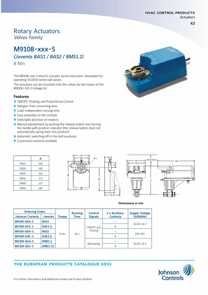
43
the european products catalogue 2011
hvac control products
Actuators
For further information and additional models see Product Bulletin
M9108-xxx-5(Joventa BAS1 / BAS2 / BMS1.1)
8 Nm
The M9108-xxx-5 electric actuator series have been developed foroperating VG1000 series ball valves.
The actuators can be mounted onto the valves by the means of theM9000-525-5 linkage kit.
Features z ON/OFF, Floating and Proportional Control
z Halogen-free connecting wire
z Load-independent running time
z Easy assembly on the console
z Selectable direction of rotation
z Manual adjustement by pushing the release button and turningthe handle with position indicator (the release button does notautomatically spring back into position)
z Automatic switching off in the limit positions
z Customized versions available
Ordering Codes
TorqueRunning
TimeControlSignals
2 x AuxiliaryContacts
Supply Voltage(50/60Hz)Johnson Controls Joventa
M9108-AGA-5 BAS1
8 Nm 30 s
ON/OFF andFloating
---AC/DC 24 V
M9108-AGC-5 BAS1.S
M9108-ADA-5 BAS2 ---230 VDC
M9108-ADC-5 BAS2.S
M9108-GGA-5 BMS1.1Modulating
---AC/DC 24 V
M9108-GGC-5 BMS1.1S
A
DN15 160
DN20 160
DN25 162
DN32 173
DN40 177
DN50 182
482.5
100
107
100
45
35
1 8 0
1 4 0
67.5
82.5
2 0
89
Minimal distance
A
199
Dimensions in mm
Rotary ActuatorsValves Family
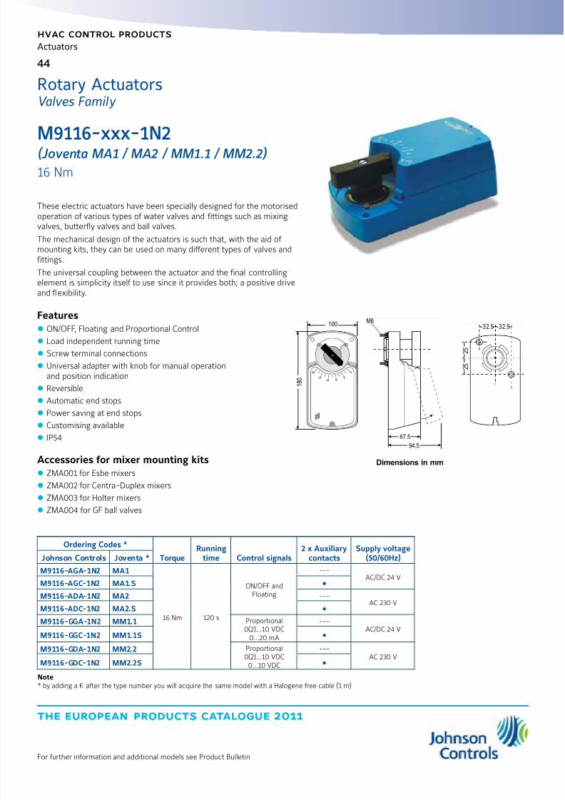
8/6/2019 Publ-6576 Prod Cat 11
http://slidepdf.com/reader/full/publ-6576-prod-cat-11 52/298
the european products catalogue 2011
hvac control products
Actuators
44
For further information and additional models see Product Bulletin
M9116-xxx-1N2(Joventa MA1 / MA2 / MM1.1 / MM2.2)
16 Nm
These electric actuators have been specially designed for the motorisedoperation of various types of water valves and fittings such as mixingvalves, butterfly valves and ball valves.
The mechanical design of the actuators is such that, with the aid of mounting kits, they can be used on many different types of valves andfittings.
The universal coupling between the actuator and the final controlling
element is simplicity itself to use since it provides both; a positive driveand flexibility.
Features z ON/OFF, Floating and Proportional Control
z Load independent running time
z Screw terminal connections
z Universal adapter with knob for manual operationand position indication
z Reversible
z Automatic end stops
z Power saving at end stops
z Customising available
z IP54
Accessories for mixer mounting kitsz ZMA001 for Esbe mixers
z ZMA002 for Centra-Duplex mixers
z ZMA003 for Holter mixers
z ZMA004 for GF ball valves
Ordering Codes *
Torque
Running
time Control signals
2 x Auxiliary
contacts
Supply voltage
(50/60Hz)Johnson Controls Joventa *M9116-AGA-1N2 MA1
16 Nm 120 s
ON/OFF andFloating
---AC/DC 24 V
M9116-AGC-1N2 MA1.S
M9116-ADA-1N2 MA2 ---AC 230 V
M9116-ADC-1N2 MA2.S
M9116-GGA-1N2 MM1.1 Proportional0(2)...10 VDC
0...20 mA
---AC/DC 24 V
M9116-GGC-1N2 MM1.1S
M9116-GDA-1N2 MM2.2 Proportional0(2)...10 VDC0...10 VDC
---AC 230 V
M9116-GDC-1N2 MM2.2S
Note* by adding a K after the type number you will acquire the same model with a Halogene free cable (1 m)
100M6
1 8 0
67.5
94.5
32.5 32.5
2 5
2 5
Dimensions in mm
Rotary ActuatorsValves Family
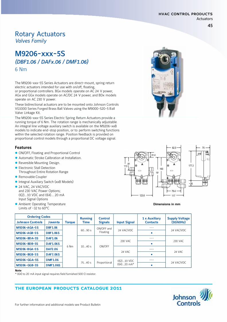
8/6/2019 Publ-6576 Prod Cat 11
http://slidepdf.com/reader/full/publ-6576-prod-cat-11 53/298
45
the european products catalogue 2011
hvac control products
Actuators
For further information and additional models see Product Bulletin
M9206-xxx-5S(DBF1.06 / DAFx.06 / DMF1.06)
6 Nm
The M9206-xxx-5S Series Actuators are direct-mount, spring returnelectric actuators intended for use with on/off, floating,or proportional controllers. BGx models operate on AC 24 V power,AGx and GGx models operate on AC/DC 24 V power, and BDx modelsoperate on AC 230 V power.
These bidirectional actuators are to be mounted onto Johnson ControlsVG1000 Series Forged Brass Ball Valves using the M9000-520-5 Ball
Valve Linkage Kit.The M9206-xxx-5S Series Electric Spring Return Actuators provide arunning torque of 6 Nm. The rotation range is mechanically adjustable.An integral line voltage auxiliary switch is available on the M9206-xxBmodels to indicate end-stop position, or to perform switching functionswithin the selected rotation range. Position feedback is provided onproportional control models through a proportional DC voltage signal.
Features z ON/OFF, Floating and Proportional Control
z Automatic Stroke Calibration at Installation.
z Reversible Mounting Design.
z
Electronic Stall DetectionThroughout Entire Rotation Range
z Removable Coupler
z Integral Auxiliary Switch (xxB Models)
z 24 VAC, 24 VAC/VDCand 230 VAC Power Options;0(2)…10 VDC and 0(4)… 20 mAInput Signal Options
z Ambient Operating TemperatureLimits of -32 to 60°C
Ordering Codes
TorqueRunning
TimeControlSignals Input Signal
1 x AuxiliaryContacts
Supply Voltage(50/60Hz)Johnson Controls Joventa
M9206-AGA-5S DBF1.06
6 Nm
60...90 sON/OFF and
Floating24 VAC/VDC
---24 VAC/VDC
M9206-AGB-5S DBF1.06S
M9206-BDA-5S DAF1.06
10...40 s ON/OFF
230 VAC---
230 VACM9206-BDB-5S DAF1.06S
M9206-BGA-5S DAF2.0624 VAC
---24 VAC
M9206-BGB-5S DAF2.06S
M9206-GGA-5S DMF1.0625.. .40 s Proport ional
0(2)...10 VDC0(4)...20 mA*
---24 VAC/VDC
M9206-GGB-5S DMF1.06S
Note* 0(4) to 20 mA input signal requires field furnished 500 O resistor.
A A
123.8
160
177.3
117
79.4
82.5 75
191
81
31.4
113
~26
Dimensions in mm
Rotary ActuatorsValves Family

8/6/2019 Publ-6576 Prod Cat 11
http://slidepdf.com/reader/full/publ-6576-prod-cat-11 54/298
the european products catalogue 2011
Manufacturer reserved the rights to change specifications without prior notice
Notes

8/6/2019 Publ-6576 Prod Cat 11
http://slidepdf.com/reader/full/publ-6576-prod-cat-11 55/298
the european products catalogue 2011
Manufacturer reserved the rights to change specifications without prior notice
index
hvac control products
ValvesTerminal Unit Valves
V5000 DN10...20, PN16 49
VG4000 DN15...20, PN16 51
VG5000
DN15...25, PN16
52
VG6000 55
Threaded Control Valves
VG1000 DN15...50, PN40 56
VG7000DN15...50, PN16
60
VGS800W1N 63
Flanged Control Valves
VG8000H DN15...150, PN25 64
VG8000N DN15...150, PN16 68
VG8300N DN40...150, PN16, pressure balanced 72
VG9000 DN15...100, PN6 and PN10 73

8/6/2019 Publ-6576 Prod Cat 11
http://slidepdf.com/reader/full/publ-6576-prod-cat-11 56/298
the european products catalogue 2011
Manufacturer reserved the rights to change specifications without prior notice
Notes
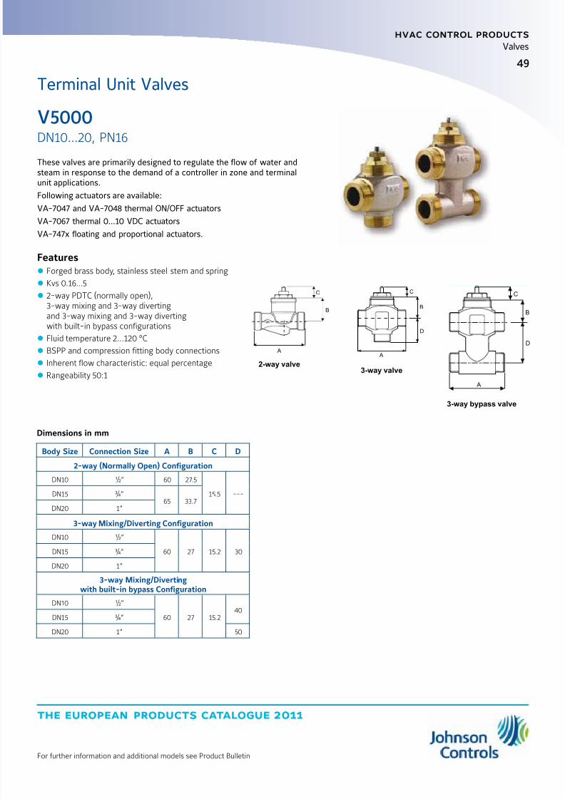
8/6/2019 Publ-6576 Prod Cat 11
http://slidepdf.com/reader/full/publ-6576-prod-cat-11 57/298
the european products catalogue 2011
For further information and additional models see Product Bulletin
hvac control products
49
Valves
V5000
DN10...20, PN16
Terminal Unit Valves
These valves are primarily designed to regulate the flow of water andsteam in response to the demand of a controller in zone and terminalunit applications.
Following actuators are available:
VA-7047 and VA-7048 thermal ON/OFF actuators
VA-7067 thermal 0...10 VDC actuators
VA-747x floating and proportional actuators.
Features z Forged brass body, stainless steel stem and spring
z Kvs 0.16...5 z 2-way PDTC (normally open),3-way mixing and 3-way divertingand 3-way mixing and 3-way divertingwith built-in bypass configurations
z Fluid temperature 2...120 °C
z BSPP and compression fitting body connections
z Inherent flow characteristic: equal percentage
z Rangeability 50:1
Dimensions in mm
Body Size Connection Size A B C D
2-way (Normally Open) Configuration
DN10 ½” 60 27.5
15.5 ---DN15 ¾”65 33.7
DN20 1”
3-way Mixing/Diverting Configuration
DN10 ½”
60 27 15.2 30DN15 ¾”
DN20 1”
3-way Mixing/Divertingwith built-in bypass Configuration
DN10 ½”
60 27 15.240
DN15 ¾”
DN20 1” 50
A
B
C
A
D
B
C
A
D
B
C
2-way valve
3-way bypass valve
3-way valve

8/6/2019 Publ-6576 Prod Cat 11
http://slidepdf.com/reader/full/publ-6576-prod-cat-11 58/298
the european products catalogue 2011
hvac control products
50
For further information and additional models see Product Bulletin
Valves
Ordering Codes*
Compression
fitting kit**
Body
Size
Kvs
(Control port)
Kvs
(By-pass port)
Close-off Pressure
(kPa)2-way configuration
V52x0ZC
--- DN10
0.16
---
400
V52x0BC 0.4
V52x0CC 0.63
V52x0DC 1
V52x0EC 1.6
V5210JC
DN15
2.5
110V5210KC 3.5
V5210MC DN20 4.5
3-way Mixing/Diverting ConfigurationV5810BC
---
DN10
0.4 0.3
120V5810CC 0.63 0.4
V5810DC 1 0.63
V5810EC 1.6 1
V5810JCDN15
2.5 1.6150
V5810KC 4 2.5
V5810MC DN20 5 3.5 110
3-way Mixing/Diverting with built-in bypass Configuration
V55x0BC
--- DN10
0.4 0.3
180V55x0CC0.63 0.4
V55x0DC 1 0.63
V55x0EC 1.6 1
V5510JC
DN15
2.5 1.6150
V5510KC 4 2.5
V5510MC DN20 5 3.5 110
Notes* x = 1: BSPP x = 9: Compression fitting
** Compression fitting kit available for DN15 and DN20DN15: 0378145015DN20: 0378145020
Terminal Unit ValvesV5000
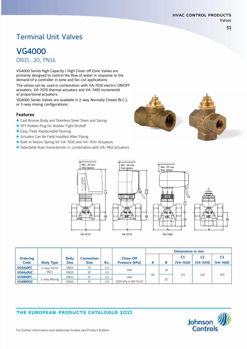
8/6/2019 Publ-6576 Prod Cat 11
http://slidepdf.com/reader/full/publ-6576-prod-cat-11 59/298
the european products catalogue 2011
For further information and additional models see Product Bulletin
hvac control products
51
Valves
VG4000
DN15...20, PN16
Terminal Unit Valves
VG4000 Series High Capacity / High Close-off Zone Valves areprimarily designed to control the flow of water in response to thedemand of a controller in zone and fan coil applications.
The valves can be used in combination with VA-7010 electric ON/OFFactuators, VA-7070 thermal actuators and VA-7450 incrementalor proportional actuators.
VG4000 Series Valves are available in 2-way Normally Closed (N.C.),or 3-way mixing configurations.
Features
z
Cast Bronze Body and Stainless Steel Stem and Spring z EPT Rubber Plug for Bubble-Tight Shutoff
z Easy, Field-Replaceable Packing
z Actuator Can Be Field Installed After Piping
z Built-In Return Spring for VA-7010 and VA-707x Actuators
z Selectable flow characteristic in combination with VA-7452 actuators
A
B
A
B
A
B
A
B
C 1
C 3
Min. 25 mmfree space
Min. 25 mmfree space Min. 25 mm
free space
xxx
PN 16
1/2"
xxx
PN 16
3/4"
xxx
PN 16
xxx
PN 16
1/2"
C 2
VA-7010 VA-7070 VA-7450
OrderingCode Body Type
BodySize
ConnectionSize Kvs
Close-Off Pressure (kPa)
Dimensions in mm
A B
C1
(VA-7010)
C2
(VA-7070)
C3
(VA-7450)
VG44y0FC 2-way PDTO(NC)
DN15 ½” 2.5340
66
19
111 110 105VG44y0GC DN20 ¾” 3.0
VG4800FC3-way Mixing
DN15 ½” 2.5 340
(200 kPa in NO Port)32
VG4800GC DN20 ¾” 3.0

8/6/2019 Publ-6576 Prod Cat 11
http://slidepdf.com/reader/full/publ-6576-prod-cat-11 60/298
the european products catalogue 2011
hvac control products
52
For further information and additional models see Product Bulletin
Valves
These valves are primarily designed to regulate the flow of water andsteam in response to the demand of a controller in zone and terminalunit applications.
Following actuators are available:
VA-7010 ON/OFF actuators
VA-7040 thermal ON/OFF actuators
VA-7060 thermal proportional actuators
VA-745x floating and proportional actuators.
Features z Forged brass body
z Kvs 0.25...5.5
z 2-way PDTO (normally open),2-way PDTC (normally closed),3-way mixing and 3-way mixingwith built-in (normally open) bypass configurations
z Fluid temperature 2...95 °C
z Built-in return spring
z BSPP male, female and compression fitting body connections
z Inherent flow characteristic: quick opening
Male Thread Connection (1/2)
Ordering Codes*BodySize
ConnectionSize
Kvs(Control Port)
Kvs(By-pass port)
Close-off Pressure(kPa)
Dimensions in mm
A B C D
2-way PDTO (Normally Open) Configuration
VG52z0AC
DN15 ½”
0.25 ---
200 68
--- ---
11VG52z0BC 0.4 --- --- ---
VG52z0CC 0.63 --- --- ---
VG52z0DC 1 --- --- ---
VG52z0EC 1.6 --- 100 72 --- --- 13.5
VG5210JCDN20 ¾”
2.5 --- 14074
---15
VG5210KC 3.5 --- 100 ---
2-way PDTC (Normally Closed) Configuration
VG54z0AC
DN15 ½”
0.25 ---
200 68
--- ---
11VG54z0BC 0.4 --- --- ---
VG54z0CC 0.63 --- --- ---
VG54z0DC 1 --- --- ---
VG54z0EC 1.6 ---
100
72 --- --- 13.5
VG5410JCDN20 ¾”
2.5 ---74
---15
VG5410KC 3.5 --- ---
Note* z = 1: BSP parallel
z = 9: Compression fitting (only for DN15 valves)
VG5000
DN15...25, PN16
Terminal Unit Valves
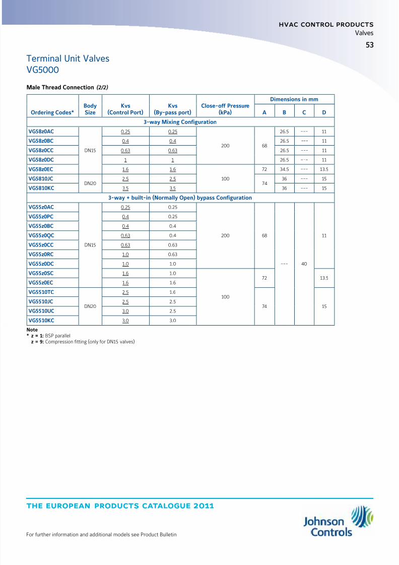
8/6/2019 Publ-6576 Prod Cat 11
http://slidepdf.com/reader/full/publ-6576-prod-cat-11 61/298
53
the european products catalogue 2011
hvac control products
For further information and additional models see Product Bulletin
Valves
Male Thread Connection (2/2)
Ordering Codes*BodySize
Kvs(Control Port)
Kvs(By-pass port)
Close-off Pressure(kPa)
Dimensions in mm
A B C D
3-way Mixing Configuration
VG58z0AC
DN15
0.25 0.25
200 68
26.5 --- 11
VG58z0BC 0.4 0.4 26.5 --- 11
VG58z0CC 0.63 0.63 26.5 --- 11
VG58z0DC 1 1 26.5 --- 11
VG58z0EC 1.6 1.6
100
72 34.5 --- 13.5
VG5810JCDN20
2.5 2.574
36 --- 15
VG5810KC 3.5 3.5 36 --- 15
3-way + built-in (Normally Open) bypass ConfigurationVG55z0AC
DN15
0.25 0.25
200 68
--- 40
11
VG55z0PC 0.4 0.25
VG55z0BC 0.4 0.4
VG55z0QC 0.63 0.4
VG55z0CC 0.63 0.63
VG55z0RC 1.0 0.63
VG55z0DC 1.0 1.0
VG55z0SC 1.6 1.0
100
72 13.5VG55z0EC 1.6 1.6
VG5510TC
DN20
2.5 1.6
74 15VG5510JC 2.5 2.5
VG5510UC 3.0 2.5
VG5510KC 3.0 3.0
Note* z = 1: BSP parallel
z = 9: Compression fitting (only for DN15 valves)
Terminal Unit ValvesVG5000
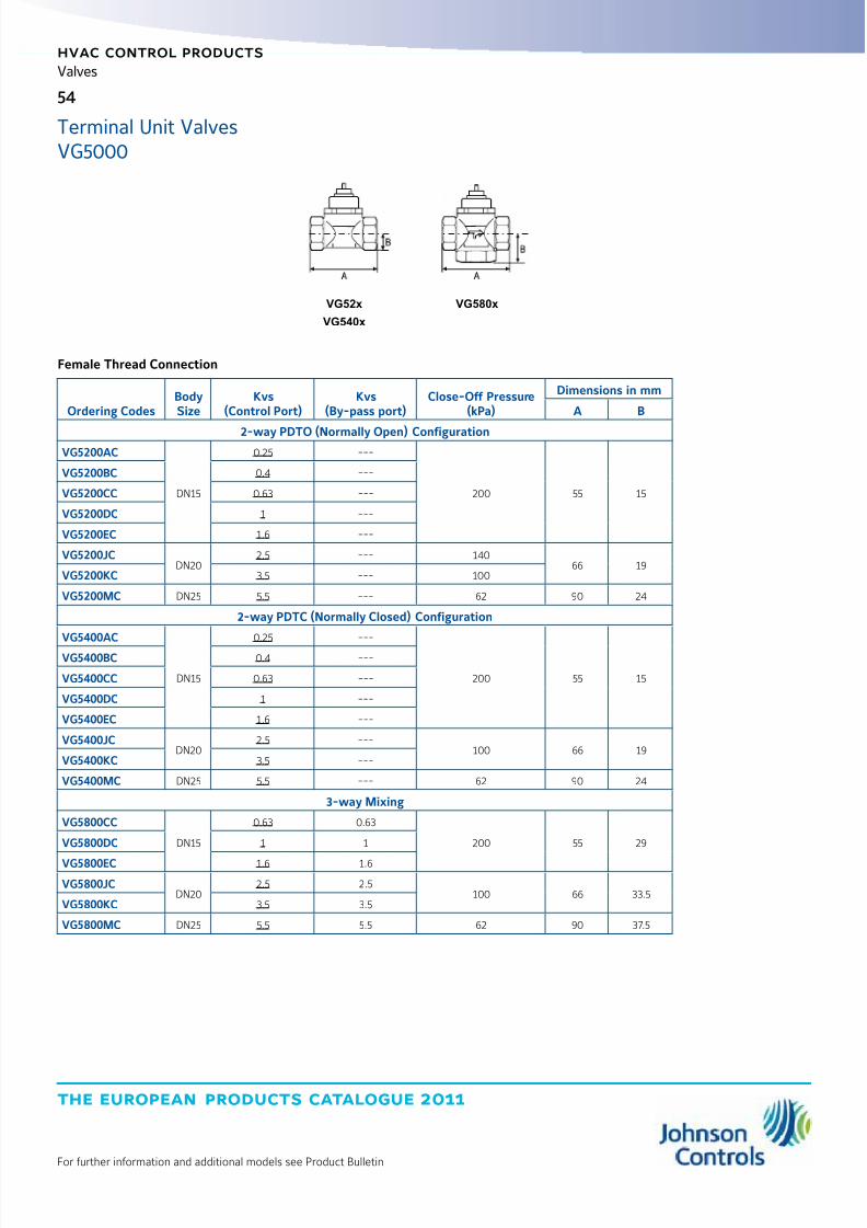
8/6/2019 Publ-6576 Prod Cat 11
http://slidepdf.com/reader/full/publ-6576-prod-cat-11 62/298
the european products catalogue 2011
hvac control products
54
For further information and additional models see Product Bulletin
Valves
Female Thread Connection
Ordering CodesBodySize
Kvs(Control Port)
Kvs(By-pass port)
Close-Off Pressure(kPa)
Dimensions in mm
A B
2-way PDTO (Normally Open) ConfigurationVG5200AC
DN15
0.25 ---
200 55 15
VG5200BC 0.4 ---
VG5200CC 0.63 ---
VG5200DC 1 ---
VG5200EC 1.6 ---
VG5200JCDN20
2.5 --- 14066 19
VG5200KC 3.5 --- 100
VG5200MC DN25 5.5 --- 62 90 24
2-way PDTC (Normally Closed) Configuration
VG5400AC
DN15
0.25 ---
200 55 15
VG5400BC 0.4 ---
VG5400CC 0.63 ---
VG5400DC 1 ---
VG5400EC 1.6 ---
VG5400JCDN20
2.5 ---100 66 19
VG5400KC 3.5 ---
VG5400MC DN25 5.5 --- 62 90 24
3-way Mixing
VG5800CC
DN15
0.63 0.63
200 55 29VG5800DC 1 1
VG5800EC 1.6 1.6
VG5800JCDN20
2.5 2.5100 66 33.5
VG5800KC 3.5 3.5
VG5800MC DN25 5.5 5.5 62 90 37.5
VG52x
VG540x
VG580x
Terminal Unit ValvesVG5000
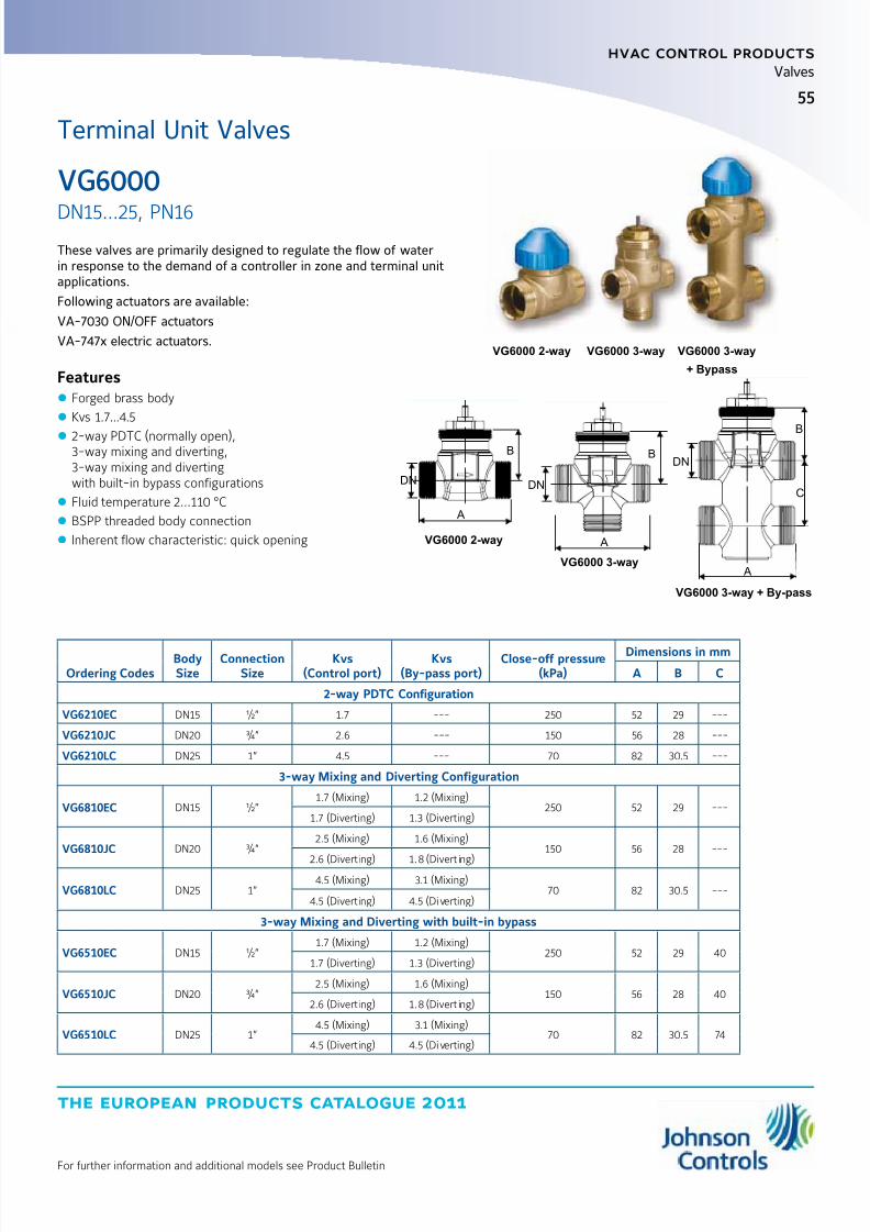
8/6/2019 Publ-6576 Prod Cat 11
http://slidepdf.com/reader/full/publ-6576-prod-cat-11 63/298
the european products catalogue 2011
For further information and additional models see Product Bulletin
hvac control products
55
Valves
These valves are primarily designed to regulate the flow of waterin response to the demand of a controller in zone and terminal unitapplications.
Following actuators are available:
VA-7030 ON/OFF actuators
VA-747x electric actuators.
Features z Forged brass body
z Kvs 1.7...4.5
z 2-way PDTC (normally open),3-way mixing and diverting,3-way mixing and divertingwith built-in bypass configurations
z Fluid temperature 2...110 °C
z BSPP threaded body connection
z Inherent flow characteristic: quick opening
DN
A
B
DN
A
B
DN
A
B
C
VG6000 2-way
VG6000 3-way
VG6000 3-way + By-pass
Ordering CodesBodySize
ConnectionSize
Kvs(Control port)
Kvs(By-pass port)
Close-off pressure(kPa)
Dimensions in mm
A B C
2-way PDTC Configuration
VG6210EC DN15 ½” 1.7 --- 250 52 29 ---
VG6210JC DN20 ¾” 2.6 --- 150 56 28 ---
VG6210LC DN25 1” 4.5 --- 70 82 30.5 ---
3-way Mixing and Diverting Configuration
VG6810EC DN15 ½”1.7 (Mixing) 1.2 (Mixing)
250 52 29 ---1.7 (Diverting) 1.3 (Diverting)
VG6810JC DN20 ¾”2.5 (Mixing) 1.6 (Mixing)
150 56 28 ---
2.6 (Divert ing) 1.8 (Divert ing)
VG6810LC DN25 1”4.5 (Mixing) 3.1 (Mixing)
70 82 30.5 ---4.5 (Divert ing) 4.5 (Diverting)
3-way Mixing and Diverting with built-in bypass
VG6510EC DN15 ½”1.7 (Mixing) 1.2 (Mixing)
250 52 29 401.7 (Diverting) 1.3 (Diverting)
VG6510JC DN20 ¾”2.5 (Mixing) 1.6 (Mixing)
150 56 28 402.6 (Divert ing) 1.8 (Divert ing)
VG6510LC DN25 1”4.5 (Mixing) 3.1 (Mixing)
70 82 30.5 744.5 (Divert ing) 4.5 (Diverting)
VG6000 2-way VG6000 3-way VG6000 3-way
+ Bypass
VG6000
DN15...25, PN16
Terminal Unit Valves

8/6/2019 Publ-6576 Prod Cat 11
http://slidepdf.com/reader/full/publ-6576-prod-cat-11 64/298
the european products catalogue 2011
hvac control products
56
For further information and additional models see Product Bulletin
Valves
These ball valves are primarily designed to regulate the flow of hot orchilled water and low-pressure steam in response to the demand of acontroller in heating, ventilating and air conditioning systems.
Following ON/OFF, floating or proportional control electric actuatorsare available:
VA9104 direct mounted Non Spring Return actuators
M9108 Non Spring Return actuators
M9206 and M9216 Spring Return actuators.
All valves and actuators available as factory mounted assemblies.
Features z Forged brass body
z Kvs 0.63...63
z 2-way, 3-way mixing and diverting configurations
z Stainless steel ball and stemFluid temperature -30...140 °C(-30 to 100 °C with VA9104)
z Inherent Equal Percentage Flow Characteristicin the in-line port of all valves
z BSPP female threaded body connections
z M9000-520-5 linkage kit availablefor field mounting to M9206 series electric actuators
z M9000-510-5 linkage kit availablefor field mounting to M9216 series electric actuators
z M9000-525-5 linkage kit availablefor field mounting to M9108 series electric actuators
Dimensions in mm
Body size A B C D E
DN1517 31
67
9
33
DN20 75 38
DN25 19 33 92 46
DN32 26 44 109 54
DN40 29 48 119 59
DN50 37 53 139 74
VG1000
DN15...50, PN40
Threaded Control Valves
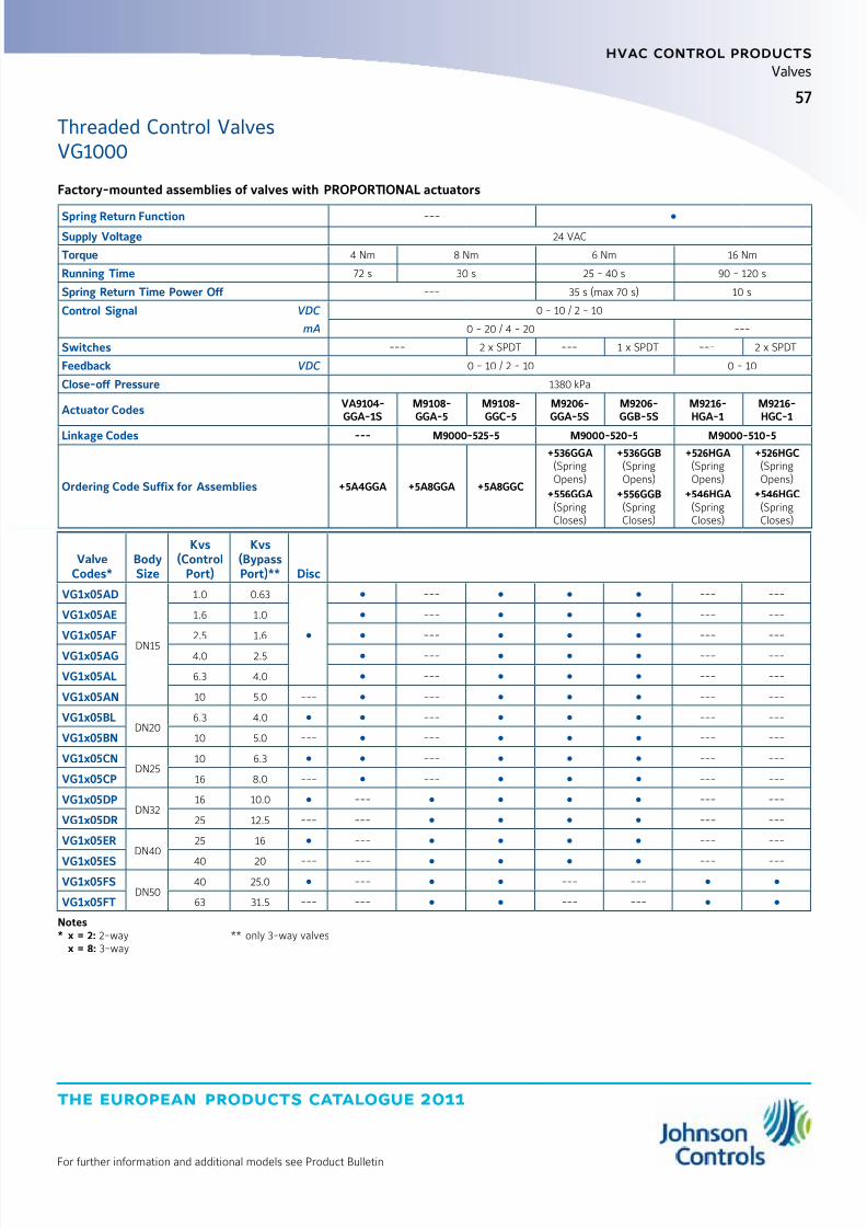
8/6/2019 Publ-6576 Prod Cat 11
http://slidepdf.com/reader/full/publ-6576-prod-cat-11 65/298
57
the european products catalogue 2011
hvac control products
For further information and additional models see Product Bulletin
Valves
Factory-mounted assemblies of valves with PROPORTIONAL actuators
Spring Return Function ---
Supply Voltage 24 VAC
Torque 4 Nm 8 Nm 6 Nm 16 Nm
Running Time 72 s 30 s 25 - 40 s 90 - 120 s
Spring Return Time Power Off --- 35 s (max 70 s) 10 s
Control Signal VDC 0 - 10 / 2 - 10
mA 0 - 20 / 4 - 20 ---
Switches --- 2 x SPDT --- 1 x SPDT --- 2 x SPDT
Feedback VDC 0 - 10 / 2 - 10 0 - 10
Close-off Pressure 1380 kPa
Actuator CodesVA9104-GGA-1S
M9108-GGA-5
M9108-GGC-5
M9206-GGA-5S
M9206-GGB-5S
M9216-HGA-1
M9216-HGC-1
Linkage Codes --- M9000-525-5 M9000-520-5 M9000-510-5
Ordering Code Suffix for Assemblies +5A4GGA +5A8GGA +5A8GGC
+536GGA(SpringOpens)
+556GGA(SpringCloses)
+536GGB(SpringOpens)
+556GGB(SpringCloses)
+526HGA(SpringOpens)
+546HGA(SpringCloses)
+526HGC(SpringOpens)
+546HGC(SpringCloses)
ValveCodes*
BodySize
Kvs(Control
Port)
Kvs(BypassPort)** Disc
VG1x05AD
DN15
1.0 0.63
--- --- ---
VG1x05AE 1.6 1.0 --- --- ---
VG1x05AF 2.5 1.6 --- --- ---
VG1x05AG 4.0 2.5 --- --- ---
VG1x05AL 6.3 4.0 --- --- ---
VG1x05AN 10 5.0 --- --- --- ---
VG1x05BLDN20
6.3 4.0 --- --- ---
VG1x05BN 10 5.0 --- --- --- ---
VG1x05CNDN25
10 6.3 --- --- ---
VG1x05CP 16 8.0 --- --- --- ---
VG1x05DPDN32
16 10.0 --- --- ---
VG1x05DR 25 12.5 --- --- --- ---
VG1x05ERDN40
25 16 --- --- ---
VG1x05ES 40 20 --- --- --- ---
VG1x05FSDN50
40 25.0 --- --- ---
VG1x05FT 63 31.5 --- --- --- ---
Notes* x = 2: 2-way x = 8: 3-way
** only 3-way valves
Threaded Control ValvesVG1000

8/6/2019 Publ-6576 Prod Cat 11
http://slidepdf.com/reader/full/publ-6576-prod-cat-11 66/298
the european products catalogue 2011
hvac control products
58
For further information and additional models see Product Bulletin
Valves
Factory-mounted assemblies of valves with FLOATING and ON/OFF actuators
Spring Return Function ---
Supply Voltage 24 VAC 230 VAC 24 VAC
Torque 4 Nm 8 Nm 6 Nm 16 Nm
Running Time 72 s 30 s 60 - 90 s 90 - 120 s
Spring Return Time Power Off ---35 s
(max 70 s)10 s
Control Signal Floating Floating with time-out and ON/OFF Floating
Switches --- 2 x SPDT --- 2 x SPDT --- 1 x SPDT --- 2 x SPDT
Feedback ---
Close-off Pressure 1380 kPa
Actuator Code
VA9104-
AGA-1S
VA9104-
IGA-1S
M9108-
AGA-5
M9108-
AGC-5
M9108-
ADA-5
M9108-
ADC-5
M9206-
AGA-5S
M9206-
AGB-5S
M9216-
AGA-1
M9216-
AGC-1
Linkage Code --- M9000-510-5 M9000-520-5 M9000-510-5
Ordering Code Suffix for Assemblies +5A4AGA +5A4IGA +5A8AGA +5A8AGC +5A8ADA +5A8ADC
+536AGA
(SpringOpens)
+556AGA
(SpringCloses)
+536AGB
(SpringOpens)
+556AGB
(SpringCloses)
+526AGA
(SpringOpens)
+546AGA
(SpringCloses)
+526AGC
(SpringOpens)
+546AGC
(SpringCloses)
ValveCode *
BodySize
Kvs(Control
Port)
Kvs(BypassPort) ** Disc
VG1x05AD
DN15
1.0 0.63
--- --- ---
VG1x05AE 1.6 1.0 --- --- ---
VG1x05AF 2.5 1.6 --- --- ---VG1x05AG 4.0 2.5 --- --- ---
VG1x05AL 6.3 4.0 --- --- ---
VG1x05AN 10 5.0 --- --- --- ---
VG1x05BLDN20
6.3 4.0 --- --- ---
VG1x05BN 10 5.0 --- --- --- ---
VG1x05CNDN25
10 6.3 --- --- ---
VG1x05CP 16 8.0 --- --- --- ---
VG1x05DPDN32
16 10.0 --- --- --- ---
VG1x05DR 25 12.5 --- --- --- --- ---
VG1x05ER
DN40
25 16 --- --- --- ---
VG1x05ES 40 20 --- --- --- --- ---
VG1x05FSDN50
40 25.0 --- --- --- ---
VG1x05FT 63 31.5 --- --- --- --- ---
Notes* x = 2: 2-way x = 8: 3-way
** only 3-way valves
Threaded Control ValvesVG1000
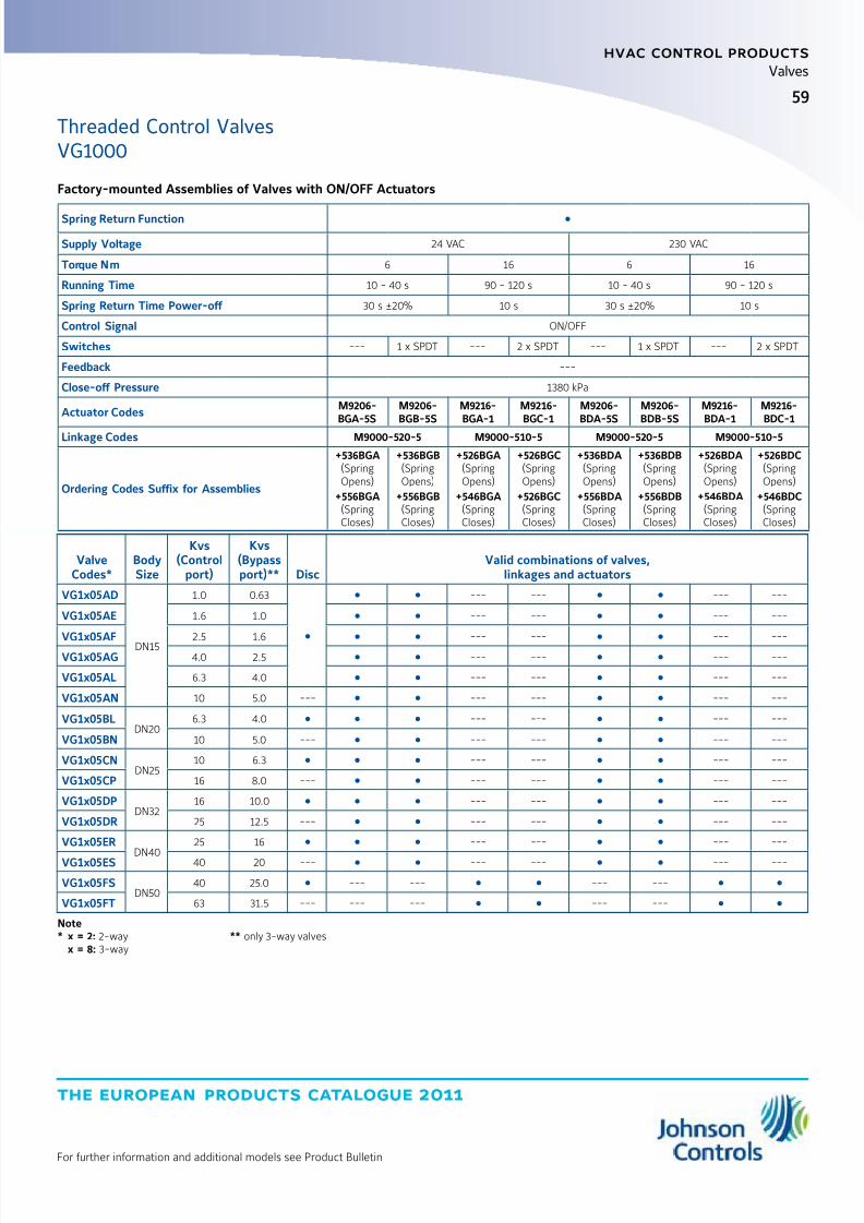
8/6/2019 Publ-6576 Prod Cat 11
http://slidepdf.com/reader/full/publ-6576-prod-cat-11 67/298
59
the european products catalogue 2011
hvac control products
For further information and additional models see Product Bulletin
Valves
Factory-mounted Assemblies of Valves with ON/OFF Actuators
Spring Return Function
Supply Voltage 24 VAC 230 VAC
Torque Nm 6 16 6 16
Running Time 10 - 40 s 90 - 120 s 10 - 40 s 90 - 120 s
Spring Return Time Power-off 30 s ±20% 10 s 30 s ±20% 10 s
Control Signal ON/OFF
Switches --- 1 x SPDT --- 2 x SPDT --- 1 x SPDT --- 2 x SPDT
Feedback ---
Close-off Pressure 1380 kPa
Actuator CodesM9206-BGA-5S
M9206-BGB-5S
M9216-BGA-1
M9216-BGC-1
M9206-BDA-5S
M9206-BDB-5S
M9216-BDA-1
M9216-BDC-1
Linkage Codes M9000-520-5 M9000-510-5 M9000-520-5 M9000-510-5
Ordering Codes Suffix for Assemblies
+536BGA(SpringOpens)
+556BGA(SpringCloses)
+536BGB(SpringOpens)
+556BGB(SpringCloses)
+526BGA(SpringOpens)
+546BGA(SpringCloses)
+526BGC(SpringOpens)
+526BGC(SpringCloses)
+536BDA(SpringOpens)
+556BDA(SpringCloses)
+536BDB(SpringOpens)
+556BDB(SpringCloses)
+526BDA(SpringOpens)
+546BDA(SpringCloses)
+526BDC(SpringOpens)
+546BDC(SpringCloses)
ValveCodes*
BodySize
Kvs(Control
port)
Kvs(Bypassport)** Disc
Valid combinations of valves,linkages and actuators
VG1x05AD
DN15
1.0 0.63
--- --- --- ---
VG1x05AE 1.6 1.0 --- --- --- ---
VG1x05AF2.5 1.6 --- --- --- ---
VG1x05AG 4.0 2.5 --- --- --- ---
VG1x05AL 6.3 4.0 --- --- --- ---
VG1x05AN 10 5.0 --- --- --- --- ---
VG1x05BLDN20
6.3 4.0 --- --- --- ---
VG1x05BN 10 5.0 --- --- --- --- ---
VG1x05CNDN25
10 6.3 --- --- --- ---
VG1x05CP 16 8.0 --- --- --- --- ---
VG1x05DPDN32
16 10.0 --- --- --- ---
VG1x05DR 25 12.5 --- --- --- --- ---
VG1x05ER
DN40
25 16 --- --- --- ---
VG1x05ES 40 20 --- --- --- --- ---
VG1x05FSDN50
40 25.0 --- --- --- ---
VG1x05FT 63 31.5 --- --- --- --- ---
Note* x = 2: 2-way x = 8: 3-way
** only 3-way valves
Threaded Control ValvesVG1000

8/6/2019 Publ-6576 Prod Cat 11
http://slidepdf.com/reader/full/publ-6576-prod-cat-11 68/298
the european products catalogue 2011
hvac control products
60
For further information and additional models see Product Bulletin
Valves
These electrically and pneumatically actuated globe valves areprimarily designed to regulate the flow of water and steam inresponse to the demand of a controller in heating, ventilatingand air conditioning systems.
Features z Cast bronze body
z Kvs 0.25...40
z 2-way PDTO (normally close),2-way PDTC (normally open),3-way mixing configurations
z Fluid temperature:Brass trim models 2...140 °C,Stainless steel trim models 2...170 °C
z BSPP male and female threaded body connections
B
A A
B
Dimensions
Dimensions in mm
Body Size A
B
2-way PDTC 2-way PDTO 3-way
DN15 76 21 39 46
DN20 81 24 41 54
DN25 104 29 44 65
DN32 119 34 51 70
DN40 130 55 70 85
DN50 150 53 72 95
VG7000
DN15...50, PN16
Threaded Control Valves

8/6/2019 Publ-6576 Prod Cat 11
http://slidepdf.com/reader/full/publ-6576-prod-cat-11 69/298
61
the european products catalogue 2011
hvac control products
For further information and additional models see Product Bulletin
Valves
2-way Configuration
BodySize Kvs
Valve stroke(mm)
Brass Trim Valves Stainless Steel Trim Valves
OrderingCodes
Close-off Pressure (kPa)
OrderingCodes
Close-off Pressure (kPa)
VA-731x *
150 N
VA-77xx
500 N
VA78xx
1000 N
VA-77xx
500 N
VA78xx
1000 N
2-way PDTC (Normally Open)
DN15
0.25
8
VG7201ASVG7201AT
1600
1600
---
VG7203AT
1600
1600
0.4VG7201BSVG7201BT
VG7203BSVG7203BT
0.63VG7201CSVG7201CT
700
VG7203CT
1.0VG7201DS
VG7201DTVG7203DT
1.6VG7201ESVG7201ET
VG7203ET
2.5VG7201FSVG7201FT
400 1490
VG7203FT
930
4.0VG7201GSVG7201GT
VG7203GT
DN20 6.3 VG7201LT 250 950 VG7203LT 595 1220
DN25 1013
VG7201NT
---
595 1235 VG7203NT 370 770
DN32 16 VG7201PT 360 750 VG7203PT 230 470
DN40 2519
VG7201RT 235 480 VG7203RT 145 300
DN50 40 VG7201ST 145 310 VG7203ST 90 190
2-way PDTO (Normally Closed)
DN15
0.25
8 mm
VG7401AT
1600
1600
---
VG7403AT
1600
1600
0.4VG7401BSVG7401BT
VG7403BT
0.63VG7401CSVG7401CT
700
VG7403CT
1.0VG7401DSVG7401DT
VG7403DT
1.6VG7401ESVG7401ET
VG7403ET
2.5VG7401FSVG7401FT
400 1490
VG7403FT
930
4.0 VG7401GSVG7401GT VG7403GT
DN20 6.3VG7401LSVG7401LT
250 950VG7403LSVG7403LT
595 1220
DN25 1013 mm
VG7401NT
---
595 1235 VG7403NT 370 770
DN32 16 VG7401PT 360 750 VG7403PT 230 470
DN40 2519 mm
VG7401RT 235 480 VG7403RT 145 300
DN50 40 VG7401ST 145 310 VG7403ST 90 190
Note* : When using VA-7310 series actuators a valve with a slotted stern (VG7xxxxS) is required.
Fluid temperature limit in conjunction with VA-7310 = 120 °C.
Ordering of factory mounted valves and electric actuators.The valves and actuators can be ordered separetely or factory mounted.
When factory mounted, please add “+M” to the order code for the actuator.
Threaded Control ValvesVG7000
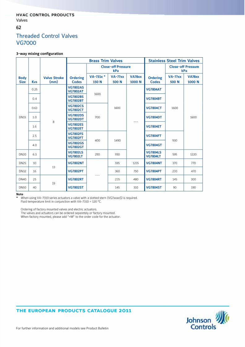
8/6/2019 Publ-6576 Prod Cat 11
http://slidepdf.com/reader/full/publ-6576-prod-cat-11 70/298
the european products catalogue 2011
hvac control products
62
For further information and additional models see Product Bulletin
Valves
3-way mixing configuration
BodySize Kvs
Valve Stroke(mm)
Brass Trim Valves Stainless Steel Trim Valves
OrderingCodes
Close-off PressurekPa
OrderingCodes
Close-off PressurekPa
VA-731x *
150 N
VA-77xx
500 N
VA78xx
1000 N
VA-77xx
500 N
VA78xx
1000 N
DN15
0.25
8
VG7802ASVG7802AT
1600
1600
---
VG7804AT
1600
1600
0.4VG7802BSVG7802BT
VG7804BT
0.63VG7802CSVG7802CT
700
VG7804CT
1.0VG7802DSVG7802DT
VG7804DT
1.6VG7802ESVG7802ET
VG7804ET
2.5VG7802FSVG7802FT
400 1490
VG7804FT
930
4.0VG7802GSVG7802GT
VG7804GT
DN20 6.3VG7802LSVG7802LT
250 950VG7804LSVG7804LT
595 1220
DN25 1013
VG7802NT
---
595 1235 VG7804NT 370 770
DN32 16 VG7802PT 360 750 VG7804PT 230 470
DN40 25
19
VG7802RT 235 480 VG7804RT 145 300
DN50 40 VG7802ST 145 310 VG7804ST 90 190
Note* When using VA-7310 series actuators a valve with a slotted stern (VG7xxxxS) is required.
Fluid temperature limit in conjunction with VA-7310 = 120 °C.
Ordering of factory mounted valves and electric actuators.The valves and actuators can be ordered separetely or factory mounted.When factory mounted, please add “+M” to the order code for the actuator.
Threaded Control ValvesVG7000
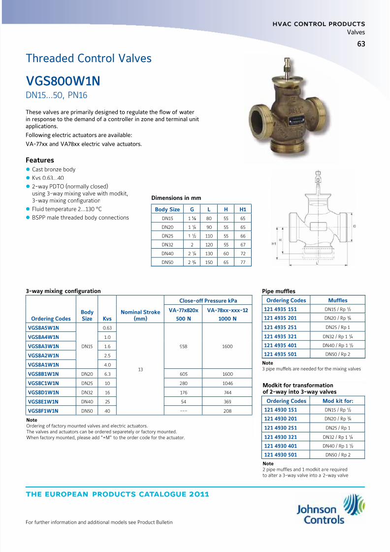
8/6/2019 Publ-6576 Prod Cat 11
http://slidepdf.com/reader/full/publ-6576-prod-cat-11 71/298
the european products catalogue 2011
For further information and additional models see Product Bulletin
hvac control products
63
Valves
These valves are primarily designed to regulate the flow of waterin response to the demand of a controller in zone and terminal unitapplications.
Following electric actuators are available:
VA-77xx and VA78xx electric valve actuators.
Features z Cast bronze body
z Kvs 0.63...40
z 2-way PDTO (normally closed)
using 3-way mixing valve with modkit,3-way mixing configuration
z Fluid temperature 2...130 °C
z BSPP male threaded body connections
Dimensions in mm
Body Size G L H H1
DN15 1 ⅛ 80 55 65
DN20 1 ¼ 90 55 65
DN25 1 ½ 110 55 66
DN32 2 120 55 67
DN40 2 ¼ 130 60 72
DN50 2 ¾ 150 65 77
3-way mixing configuration
Ordering CodesBodySize Kvs
Nominal Stroke(mm)
Close-off Pressure kPa
VA-77x820x
500 N
VA-78xx-xxx-12
1000 N
VGS8A5W1N
DN15
0.63
13
958 1600
VGS8A4W1N 1.0
VGS8A3W1N 1.6
VGS8A2W1N 2.5
VGS8A1W1N 4.0
VGS8B1W1N DN20 6.3 605 1600
VGS8C1W1N DN25 10 280 1046
VGS8D1W1N DN32 16 176 744
VGS8E1W1N DN40 25 54 369
VGS8F1W1N DN50 40 --- 208
NoteOrdering of factory mounted valves and electric actuators.The valves and actuators can be ordered separetely or factory mounted.When factory mounted, please add “+M” to the order code for the actuator.
Pipe mufflesOrdering Codes Muffles
121 4935 151 DN15 / Rp ½
121 4935 201 DN20 / Rp ¾
121 4935 251 DN25 / Rp 1
121 4935 321 DN32 / Rp 1 ¼
121 4935 401 DN40 / Rp 1 ½
121 4935 501 DN50 / Rp 2
Note3 pipe muffels are needed for the mixing valves
Modkit for transformationof 2-way into 3-way valves
Ordering Codes Mod kit for:
121 4930 151 DN15 / Rp ½
121 4930 201 DN20 / Rp ¾
121 4930 251 DN25 / Rp 1
121 4930 321 DN32 / Rp 1 ¼
121 4930 401 DN40 / Rp 1 ½
121 4930 501 DN50 / Rp 2
Note2 pipe muffles and 1 modkit are requiredto alter a 3-way valve into a 2-way valve
VGS800W1N
DN15...50, PN16
Threaded Control Valves

8/6/2019 Publ-6576 Prod Cat 11
http://slidepdf.com/reader/full/publ-6576-prod-cat-11 72/298
the european products catalogue 2011
hvac control products
64
For further information and additional models see Product Bulletin
Valves
These flanged valves are primarily designed to regulate the flow of water and steam in response to the demand of a controller, in heating,ventilating and air conditioning systems.
A variety of electric and pneumatic actuators are available.
Features z Nodular cast iron body
z Kvs 0.4...350
z 2-way PDTC (normally open),3-way mixing and 3-way diverting configurations
z Fluid temperature 2...200 °C,with glycerin cup: -20...200 °Cwith cooling fins: up to 280 °C
z DIN Flanged
Dimensions in mm
Body Size B D1 D2 D3 d H1 H5 Bolts HolesDN15 130 95 65 45 13.5 100 76 M12 x 45 4
DN20 150 105 75 58 13.5 106 76 M12 x 50 4
DN25 160 115 85 68 13.5 106 76 M12 x 50 4
DN32 180 140 100 78 17.5 123 81 M16 x 55 4
DN40 200 150 110 88 17.5 140 78 M16 x 55 4
DN50 230 165 125 102 17.5 145 101 M16 x 60 4
DN65 290 185 145 122 17.5 156 102 M16 x 60 8
DN80 310 200 160 138 17.5 180 108 M16 x 65 8
DN100 350 235 190 162 22 225 136 M20 x 70 8
DN125 400 270 220 188 26 255 155 M24 x 75 8
DN150 480 300 250 218 26 290 175 M24 x 80 8
VG8000H
DN15...150, PN25
Flanged Control Valves

8/6/2019 Publ-6576 Prod Cat 11
http://slidepdf.com/reader/full/publ-6576-prod-cat-11 73/298
65
the european products catalogue 2011
hvac control products
For further information and additional models see Product Bulletin
Valves
Flanged Control ValvesVG8000H
2-way PDTC (Normally Open) Configuration
Ordering Codes*BodySize Kvs
Close-off Pressure kPa
FA-2000-741x
2200 N
FA-2000-751x
2400 N
FA-3300-741x
6000 N
RA-3000-732x
3000 N
RA-3100-8226
1700 N
VA1x20**
2000 N
VA1125**
500 N
VA78xx
1000 N
VG82A4S1H
DN15
1.0
---
---
---
--- ---2500 2500
2500VG82A3S1H 1.6
VG82A2S1H 2.5
VG82A1S1H 4.0
VG82B1S1H DN20 6.3 2030
VG82C1S1H DN25 10 1360
VG82D1S1H DN32 16 660
VG82E1S1H DN40 25 1550 2000 370
VG82F1S1H DN50 40 920 1300 600 750 1020
---
VG82G1S1H DN65 63 710 1010 450 580 750
VG82H1S1H DN80 100 330 480 200 260 370
VG82J1S1H DN100 160 180
---
720 290 100 140 210
VG82K1S1H DN125 250 100 450 170---
80 120
VG82L1S1H DN150 350 50 270 100 40 70
Notes* For factory mounted valve actuators just add “+M” to the type model number For ordering a valve with Cooling fin, add suffix “10” to the ordering code: i.e. VG8xxxS1H10 For ordering a valve with Glycerine cup packing, add suffix “20” to the ordering code: i.e. VG8xxxS1H20.
Reduced kvs coefficients are available on request.
** For fluid temperature >140 °C the extension kit VA1000-EP must be mounted. Max-Fluid temperature must not exceed 200 °C.
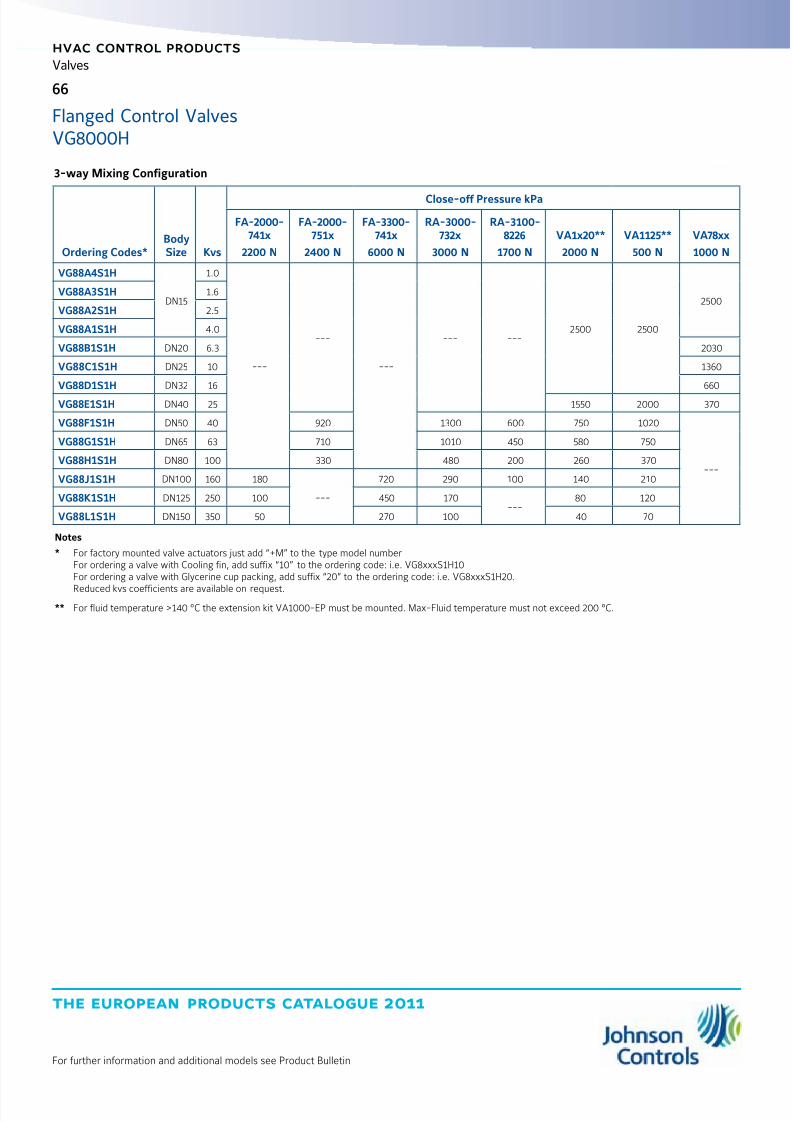
8/6/2019 Publ-6576 Prod Cat 11
http://slidepdf.com/reader/full/publ-6576-prod-cat-11 74/298
the european products catalogue 2011
hvac control products
66
For further information and additional models see Product Bulletin
Valves
3-way Mixing Configuration
Ordering Codes*BodySize Kvs
Close-off Pressure kPa
FA-2000-741x
2200 N
FA-2000-751x
2400 N
FA-3300-741x
6000 N
RA-3000-732x
3000 N
RA-3100-8226
1700 N
VA1x20**
2000 N
VA1125**
500 N
VA78xx
1000 N
VG88A4S1H
DN15
1.0
---
---
---
--- ---2500 2500
2500VG88A3S1H 1.6
VG88A2S1H 2.5
VG88A1S1H 4.0
VG88B1S1H DN20 6.3 2030
VG88C1S1H DN25 10 1360
VG88D1S1H DN32 16 660
VG88E1S1H DN40 25 1550 2000 370
VG88F1S1H DN50 40 920 1300 600 750 1020
---
VG88G1S1H DN65 63 710 1010 450 580 750
VG88H1S1H DN80 100 330 480 200 260 370
VG88J1S1H DN100 160 180
---
720 290 100 140 210
VG88K1S1H DN125 250 100 450 170---
80 120
VG88L1S1H DN150 350 50 270 100 40 70
Notes
* For factory mounted valve actuators just add “+M” to the type model number For ordering a valve with Cooling fin, add suffix “10” to the ordering code: i.e. VG8xxxS1H10 For ordering a valve with Glycerine cup packing, add suffix “20” to the ordering code: i.e. VG8xxxS1H20.
Reduced kvs coefficients are available on request.
** For fluid temperature >140 °C the extension kit VA1000-EP must be mounted. Max-Fluid temperature must not exceed 200 °C.
Flanged Control ValvesVG8000H
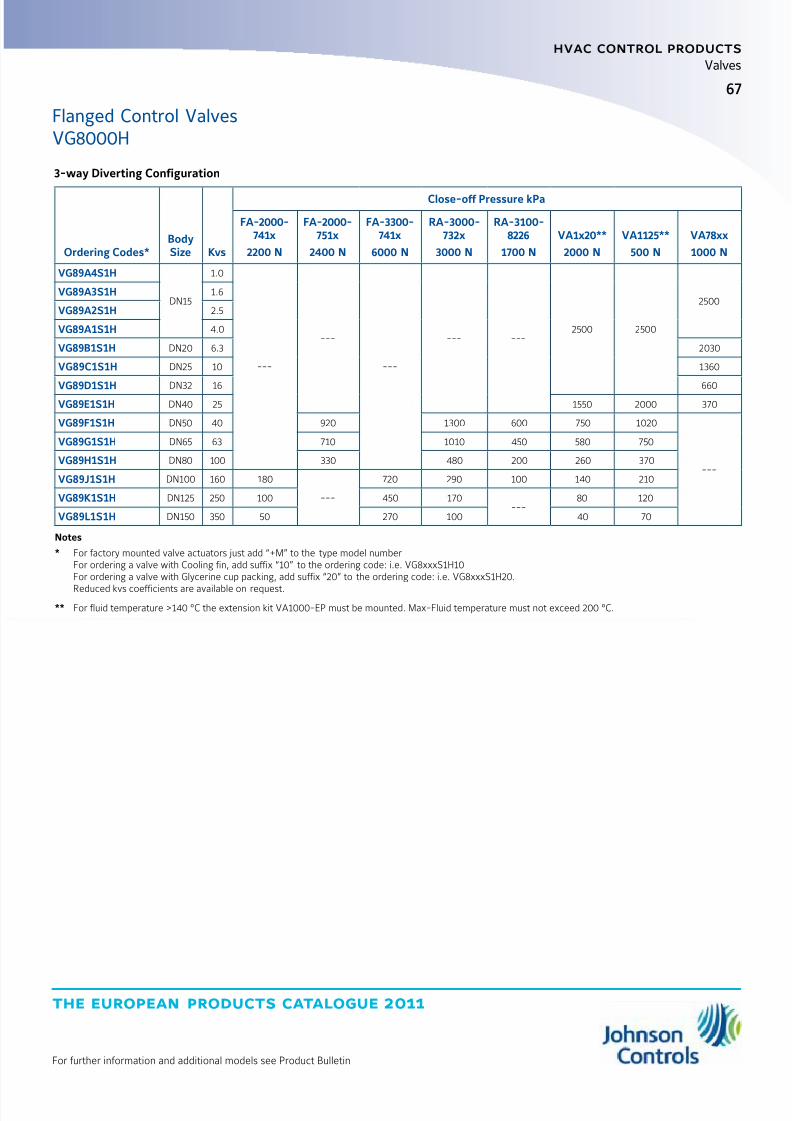
8/6/2019 Publ-6576 Prod Cat 11
http://slidepdf.com/reader/full/publ-6576-prod-cat-11 75/298
67
the european products catalogue 2011
hvac control products
For further information and additional models see Product Bulletin
Valves
3-way Diverting Configuration
Ordering Codes*BodySize Kvs
Close-off Pressure kPa
FA-2000-741x
2200 N
FA-2000-751x
2400 N
FA-3300-741x
6000 N
RA-3000-732x
3000 N
RA-3100-8226
1700 N
VA1x20**
2000 N
VA1125**
500 N
VA78xx
1000 N
VG89A4S1H
DN15
1.0
---
---
---
--- ---2500 2500
2500VG89A3S1H 1.6
VG89A2S1H 2.5
VG89A1S1H 4.0
VG89B1S1H DN20 6.3 2030
VG89C1S1H DN25 10 1360
VG89D1S1H DN32 16 660
VG89E1S1H DN40 25 1550 2000 370
VG89F1S1H DN50 40 920 1300 600 750 1020
---
VG89G1S1H DN65 63 710 1010 450 580 750
VG89H1S1H DN80 100 330 480 200 260 370
VG89J1S1H DN100 160 180
---
720 290 100 140 210
VG89K1S1H DN125 250 100 450 170---
80 120
VG89L1S1H DN150 350 50 270 100 40 70
Notes
* For factory mounted valve actuators just add “+M” to the type model number For ordering a valve with Cooling fin, add suffix “10” to the ordering code: i.e. VG8xxxS1H10 For ordering a valve with Glycerine cup packing, add suffix “20” to the ordering code: i.e. VG8xxxS1H20.
Reduced kvs coefficients are available on request.
** For fluid temperature >140 °C the extension kit VA1000-EP must be mounted. Max-Fluid temperature must not exceed 200 °C.
Flanged Control ValvesVG8000H
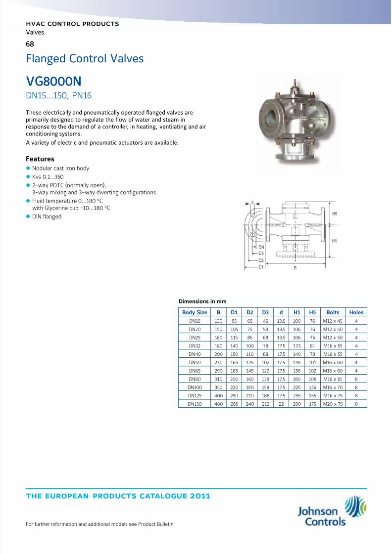
8/6/2019 Publ-6576 Prod Cat 11
http://slidepdf.com/reader/full/publ-6576-prod-cat-11 76/298
the european products catalogue 2011
hvac control products
68
For further information and additional models see Product Bulletin
Valves
VG8000N
DN15...150, PN16
Flanged Control Valves
These electrically and pneumatically operated flanged valves areprimarily designed to regulate the flow of water and steam inresponse to the demand of a controller, in heating, ventilating and airconditioning systems.
A variety of electric and pneumatic actuators are available.
Features z Nodular cast iron body
z Kvs 0.1...350
z 2-way PDTC (normally open),
3-way mixing and 3-way diverting configurations z Fluid temperature 0...180 °Cwith Glycerine cup -10...180 °C
z DIN flanged
Dimensions in mm
Body Size B D1 D2 D3 d H1 H5 Bolts Holes
DN15 130 95 65 45 13.5 100 76 M12 x 45 4
DN20 150 105 75 58 13.5 106 76 M12 x 50 4
DN25 160 115 85 68 13.5 106 76 M12 x 50 4
DN32 180 140 100 78 17.5 123 81 M16 x 55 4
DN40 200 150 110 88 17.5 140 78 M16 x 55 4
DN50 230 165 125 102 17.5 145 101 M16 x 60 4
DN65 290 185 145 122 17.5 156 102 M16 x 60 4
DN80 310 200 160 138 17.5 180 108 M16 x 65 8
DN100 350 220 180 158 17.5 225 136 M16 x 70 8
DN125 400 250 210 188 17.5 255 155 M16 x 75 8
DN150 480 285 240 212 22 290 175 M20 x 75 8

8/6/2019 Publ-6576 Prod Cat 11
http://slidepdf.com/reader/full/publ-6576-prod-cat-11 77/298
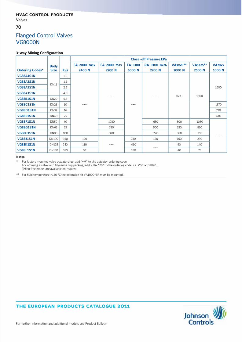
8/6/2019 Publ-6576 Prod Cat 11
http://slidepdf.com/reader/full/publ-6576-prod-cat-11 78/298
the european products catalogue 2011
hvac control products
70
For further information and additional models see Product Bulletin
Valves
3-way Mixing Configuration
Ordering Codes*BodySize Kvs
Close-off Pressure kPaFA-2000-741x
2400 N
FA-2000-751x
2200 N
FA-3300
6000 N
RA-3100-8226
2700 N
VA1x20**
2000 N
VA1125**
2500 N
VA78xx
1000 N
VG88A4S1N
DN15
1.0
---
---
---
--- 1600 1600
1600
VG88A3S1N 1.6
VG88A2S1N 2.5
VG88A1S1N 4.0
VG88B1S1N DN20 6.3
VG88C1S1N DN25 10 1570
VG88D1S1N DN32 16 770
VG88E1S1N DN40 25 440
VG88F1S1N DN50 40 1030 650 800 1080
---
VG88G1S1N DN65 63 790 500 630 830
VG88H1S1N DN80 100 370 220 380 390
VG88J1S1N DN100 160 190
---
740 120 160 230
VG88K1S1N DN125 250 110 460---
90 140
VG88L1S1N DN150 350 50 280 40 75
Notes
* For factory mounted valve actuators just add “+M” to the actuator ordering code For ordering a valve with Glycerine cup packing, add suffix “20” to the ordering code: i.e. VG8xxxS1H20. Teflon free model are available on request.
** For fluid temperature >140 °C the extension kit VA1000-EP must be mounted.
Flanged Control ValvesVG8000N

8/6/2019 Publ-6576 Prod Cat 11
http://slidepdf.com/reader/full/publ-6576-prod-cat-11 79/298
71
the european products catalogue 2011
hvac control products
For further information and additional models see Product Bulletin
Valves
3-way Diverting Configuration
Ordering Codes*BodySize Kvs
Close-off Pressure kPaFA-2000-741x
2400 N
FA-2000-751x
2200 N
FA-3300
6000 N
RA-3100-8226
2700 N
VA1x20**
2000 N
VA1125**
2500 N
VA78xx
1000 N
VG89A4S1N
DN15
1.0
---
---
---
--- 1600 1600
1600
VG89A3S1N 1.6
VG89A2S1N 2.5
VG89A1S1N 4.0
VG89B1S1N DN20 6.3
VG89C1S1N DN25 10 1570
VG89D1S1N DN32 16 770
VG89E1S1N DN40 25 440
VG89F1S1N DN50 40 1030 650 800 1080
---
VG89G1S1N DN65 63 790 500 630 830
VG89H1S1N DN80 100 370 220 380 390
VG89J1S1N DN100 160 190
---
740 120 160 230
VG89K1S1N DN125 250 110 460---
90 140
VG89L1S1N DN150 350 50 280 40 75
Notes
* For factory mounted valve actuators just add “+M” to the actuator ordering code For ordering a valve with Glycerine cup packing, add suffix “20” to the ordering code: i.e. VG8xxxS1H20. Teflon free model are available on request.
** For fluid temperature >140 °C the extension kit VA1000-EP must be mounted.
Flanged Control ValvesVG8000N

8/6/2019 Publ-6576 Prod Cat 11
http://slidepdf.com/reader/full/publ-6576-prod-cat-11 80/298
the european products catalogue 2011
hvac control products
72
For further information and additional models see Product Bulletin
Valves
VG8300N
DN40...150, PN16These pressure balanced flanged valves are primarily designed toregulate the flow of water and steam in response to the demand of acontroller, in heating, ventilating and air conditioning systems.
These valves have a specially designed plug, which through specificbalancing of pressures allows higher close-off pressures with standardactuator combinations.
A variety of electric and pneumatic actuators are available.
Features z Nodular cast iron bodies
z Kvs 25...350z 2-way PDTC (normally open) configuration
z PN16Fluid temperature 2...180 °Cwith Glycerin cup -10...180 °C
z Pressure balanced valve plug
z DIN flanged
Dimensions in mm
Body Size B D1 D2 D3 d H1 H5 Bolts Holes
DN40 200 150 110 88 17.5 140 78 M16 x 55 4
DN50 230 165 125 102 17.5 145 101 M16 x 60 4
DN65 290 185 145 122 17.5 156 102 M16 x 60 4
DN80 310 200 160 138 17.5 180 108 M16 x 65 8
DN100 350 220 180 158 17.5 225 136 M16 x 70 8
DN125 400 250 210 188 17.5 255 155 M16 x 75 8
DN150 480 285 240 212 22 290 175 M20 x 75 8
Flanged Control Valves
Ordering Codes*
Body
Size Kvs
Close-off Pressure kPa
Spring Return Non Spring Return
FA-2000-741x
2200 N
VA1x20**
2000 N
RA-3100-8126
1200 N
RA-3100-8226
1700 N
VA1125**
2500 N
VA78xx
1000 NVG83E1S1N DN40 25
--- 1600
1600 ---
1600
1600
VG83F1S1N DN50 40
--- 1600 ---
VG83G1S1N DN65 63
VG83H1S1N DN80 100
VG83J1S1N DN100 160
1600
1500
VG83K1S1N DN125 250 1400 1500
VG83L1S1N DN150 350 1000 1400
Notes
* For factory mounted valve actuators just add “+M” to the actuator ordering code.
** For fluid temperature >140 °C the extension kit VA1000-EP must be mounted.

8/6/2019 Publ-6576 Prod Cat 11
http://slidepdf.com/reader/full/publ-6576-prod-cat-11 81/298
the european products catalogue 2011
For further information and additional models see Product Bulletin
hvac control products
73
Valves
VG9000
DN15...100, PN6 and PN10
Dimensions in mm
BodySize
PN6 PN10
B D1 D2 D3 d H1 Holes B D1 D2 D3 d H1 Holes
DN15 130 80 55 38 11 65 4 130 95 65 46 14 65 4
DN20 140 90 65 48 11 70 4 150 105 75 56 14 75 4
DN25 150 100 75 58 11 75 4 160 115 85 65 14 80 4
DN32 180 120 90 69 14 90 4 180 140 100 76 19 90 4
DN40 180 130 100 78 14 90 4 200 150 110 84 19 100 4
DN50 200 140 110 88 14 100 4 230 165 125 99 19 115 4
DN65 240 160 130 108 14 120 4 290 185 145 118 19 145 4
DN80 260 190 150 124 19 130 4 310 200 160 132 19 155 8
DN100 300 210 170 144 19 150 4 350 220 180 156 19 175 8
These flanged valves are primarily designed to regulatethe flow of water and low pressure steam in responseto the demand of a controller, in heating, ventilatingand air conditioning systems.
Following electric actuators are available:
VA-7700 for DN15...50 valves
VA7810 for DN15...65 valves
VA1000 for DN65...100 valves.
Features
z Nodular cast iron body z Kvs 0.63...160
z 2-way PDTO (normally closed)and 3-way mixing configurations
z Fluid temperature 2...140 °C
z DIN flanged
Flanged Control Valves
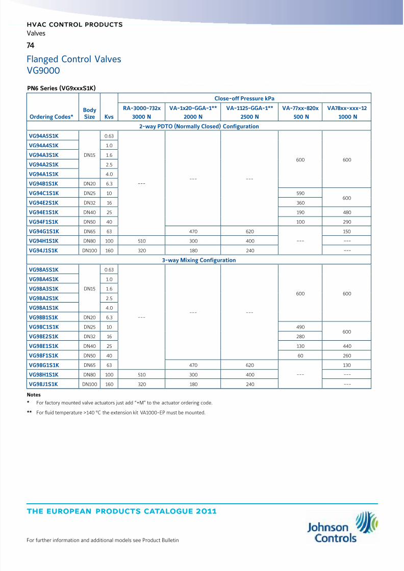
8/6/2019 Publ-6576 Prod Cat 11
http://slidepdf.com/reader/full/publ-6576-prod-cat-11 82/298
the european products catalogue 2011
hvac control products
74
For further information and additional models see Product Bulletin
Valves
Flanged Control ValvesVG9000
PN6 Series (VG9xxxS1K)
Ordering Codes*BodySize Kvs
Close-off Pressure kPaRA-3000-732x
3000 N
VA-1x20-GGA-1**
2000 N
VA-1125-GGA-1**
2500 N
VA-77xx-820x
500 N
VA78xx-xxx-12
1000 N
2-way PDTO (Normally Closed) Configuration
VG94A5S1K
DN15
0.63
------ ---
600 600
VG94A4S1K 1.0
VG94A3S1K 1.6
VG94A2S1K 2.5
VG94A1S1K 4.0
VG94B1S1K DN20 6.3
VG94C1S1K DN25 10 590
600VG94E2S1K DN32 16 360
VG94E1S1K DN40 25 190 480
VG94F1S1K DN50 40 100 290
VG94G1S1K DN65 63 470 620
---
150
VG94H1S1K DN80 100 510 300 400 ---
VG94J1S1K DN100 160 320 180 240 ---
3-way Mixing Configuration
VG98A5S1K
DN15
0.63
------ ---
600 600
VG98A4S1K 1.0
VG98A3S1K 1.6
VG98A2S1K 2.5VG98A1S1K 4.0
VG98B1S1K DN20 6.3
VG98C1S1K DN25 10 490600
VG98E2S1K DN32 16 280
VG98E1S1K DN40 25 130 440
VG98F1S1K DN50 40 60 260
VG98G1S1K DN65 63 470 620
---
130
VG98H1S1K DN80 100 510 300 400 ---
VG98J1S1K DN100 160 320 180 240 ---
Notes
* For factory mounted valve actuators just add “+M” to the actuator ordering code.
** For fluid temperature >140 °C the extension kit VA1000-EP must be mounted.
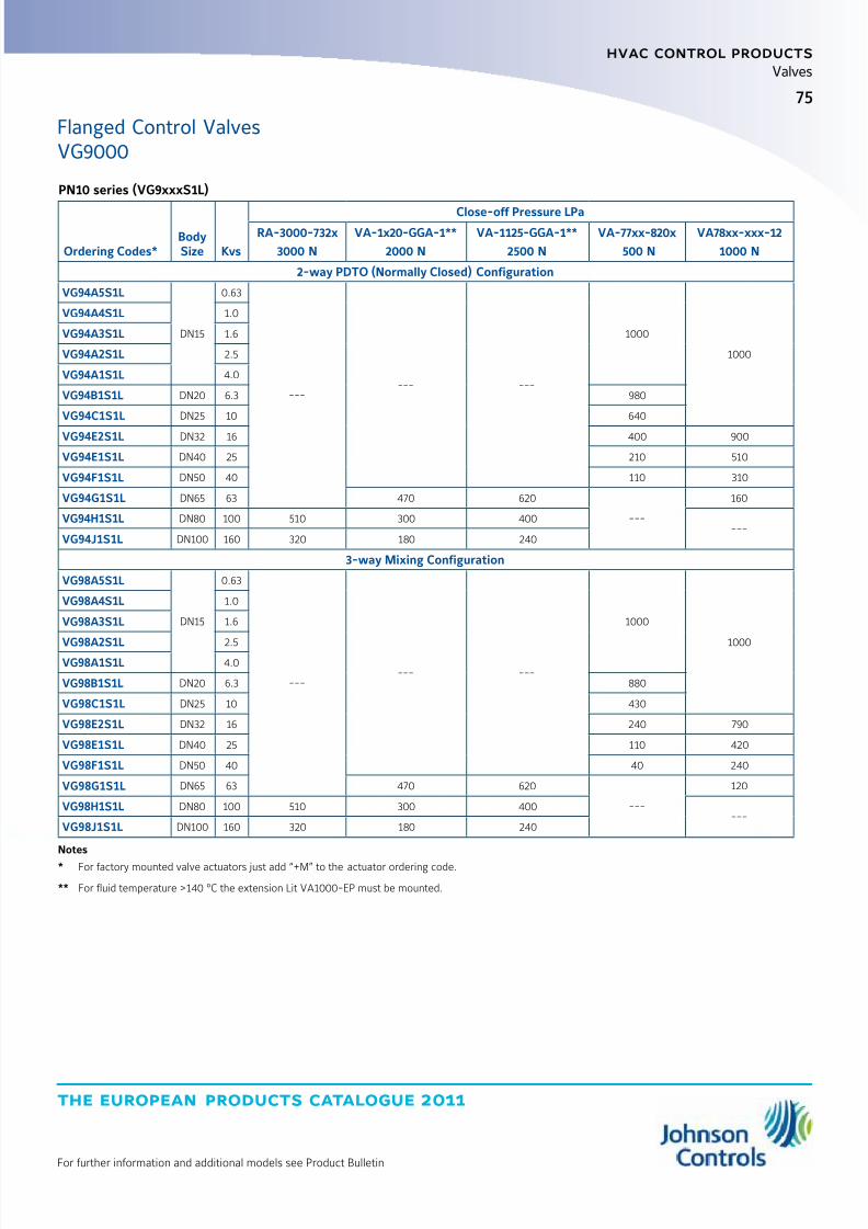
8/6/2019 Publ-6576 Prod Cat 11
http://slidepdf.com/reader/full/publ-6576-prod-cat-11 83/298
75
the european products catalogue 2011
hvac control products
For further information and additional models see Product Bulletin
Valves
PN10 series (VG9xxxS1L)
Ordering Codes*BodySize Kvs
Close-off Pressure LPaRA-3000-732x
3000 N
VA-1x20-GGA-1**
2000 N
VA-1125-GGA-1**
2500 N
VA-77xx-820x
500 N
VA78xx-xxx-12
1000 N
2-way PDTO (Normally Closed) Configuration
VG94A5S1L
DN15
0.63
------ ---
1000
1000
VG94A4S1L 1.0
VG94A3S1L 1.6
VG94A2S1L 2.5
VG94A1S1L 4.0
VG94B1S1L DN20 6.3 980
VG94C1S1L DN25 10 640
VG94E2S1L DN32 16 400 900
VG94E1S1L DN40 25 210 510
VG94F1S1L DN50 40 110 310
VG94G1S1L DN65 63 470 620
---
160
VG94H1S1L DN80 100 510 300 400---
VG94J1S1L DN100 160 320 180 240
3-way Mixing Configuration
VG98A5S1L
DN15
0.63
------ ---
1000
1000
VG98A4S1L 1.0
VG98A3S1L 1.6
VG98A2S1L 2.5VG98A1S1L 4.0
VG98B1S1L DN20 6.3 880
VG98C1S1L DN25 10 430
VG98E2S1L DN32 16 240 790
VG98E1S1L DN40 25 110 420
VG98F1S1L DN50 40 40 240
VG98G1S1L DN65 63 470 620
---
120
VG98H1S1L DN80 100 510 300 400---
VG98J1S1L DN100 160 320 180 240
Notes
* For factory mounted valve actuators just add “+M” to the actuator ordering code.
** For fluid temperature >140 °C the extension Lit VA1000-EP must be mounted.
Flanged Control ValvesVG9000

8/6/2019 Publ-6576 Prod Cat 11
http://slidepdf.com/reader/full/publ-6576-prod-cat-11 84/298
the european products catalogue 2011
Manufacturer reserved the rights to change specifications without prior notice
Notes
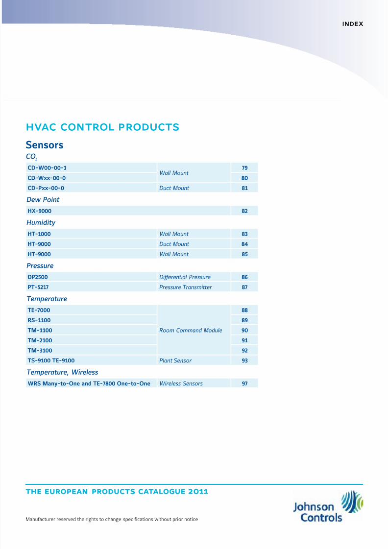
8/6/2019 Publ-6576 Prod Cat 11
http://slidepdf.com/reader/full/publ-6576-prod-cat-11 85/298
the european products catalogue 2011
Manufacturer reserved the rights to change specifications without prior notice
index
hvac control products
SensorsCO
2
CD-W00-00-1Wall Mount
79
CD-Wxx-00-0 80
CD-Pxx-00-0 Duct Mount 81
Dew Point
HX-9000 82
Humidity
HT-1000 Wall Mount 83
HT-9000 Duct Mount 84
HT-9000 Wall Mount 85
Pressure
DP2500 Differential Pressure 86
PT-5217 Pressure Transmitter 87Temperature
TE-7000
Room Command Module
88
RS-1100 89
TM-1100 90
TM-2100 91
TM-3100 92
TS-9100 TE-9100 Plant Sensor 93
Temperature, Wireless
WRS Many-to-One and TE-7800 One-to-One Wireless Sensors 97

8/6/2019 Publ-6576 Prod Cat 11
http://slidepdf.com/reader/full/publ-6576-prod-cat-11 86/298
the european products catalogue 2011
Manufacturer reserved the rights to change specifications without prior notice
Notes

8/6/2019 Publ-6576 Prod Cat 11
http://slidepdf.com/reader/full/publ-6576-prod-cat-11 87/298
the european products catalogue 2011
For further information and additional models see Product Bulletin
hvac control products
79
Sensors
The CD-W00-00-1 Series Wall Mount CO2Sensors feature a Carbon
Dioxide (CO2) transmitter for measuring and transmitting CO
2levels,
ranging from 0 to 2,000 parts per million (ppm), within HeatingVentilating, and Air Conditioning (HVAC) CO
2applications.
Specific HVAC CO2applications include Demand Control Ventilation
(DCV), fresh air and indoor Air Quality (IAQ), and rooftop air handlingEconomizer controls system.
This compact devices produces 0 to10 V (default), 0 to 20 mA and4 to 20 mA signals.
They are designed to work in stand-alone mode, Connected toMetasys system, as part on any integrated Building Automation System
(BAS) and are easy to install and requires no maintenance or fieldcalibration.
Features z Power supply: 20 to 30 VAC (18 to 30 VDC), Class 2
z Response time (0 to 63%): 1 minute
z Accuracy at 25 °C: ± 50 ppm + 3.0% of reading
z Operating temperature Range: -5 to 45 °C
z Humidity Range: 0 to 85%
CD-W00-00-1
Wall Mount
CO2
120
80
120
25
32
Dimensions in mm
Ordering Codes Description
CD-W00-00-1Wall Mount CO
2Transmitter
Accessories
Ordering Codes Description
ACC-DWCLIP-0 Drywall Spring-Clip Mounting Kit

8/6/2019 Publ-6576 Prod Cat 11
http://slidepdf.com/reader/full/publ-6576-prod-cat-11 88/298
the european products catalogue 2011
hvac control products
80
For further information and additional models see Product Bulletin
Sensors
CD-Wxx-00-0
Wall MountThe CD-Wxx-00-0 Series Wall Mount CO
2sensors feature a Carbon
Dioxide (CO2) transmitter for measuring and transmitting CO
2levels,
ranging from 0 to 2,000 parts per million (ppm), within HeatingVentilating, and Air Conditioning (HVAC) CO
2applications. Specific
HVAC CO2applications include Demand Control Ventilation (DCV),
fresh air and indoor Air Quality (IAQ), and rooftop air handlingEconomizer controls system.
This compact devices produces 0 to10 V (default), 0 to 20 mA and4 to 20 mA signals.
They are designed to work in stand-alone mode, Connected to Metasyssystem, as part on any integrated Building Automation System (BAS)
and are easy to install and requires no maintenance or field calibrationfield calibration.
Features z Power supply: 20 to 30 VAC (18 to 30 VDC), Class 2
z Response time (0 to 63%): 1 minute
z Accuracy at 20 °C: ± 30 ppm + 2.0% of reading
z Operating temperature Range: -5 to 45 °C
z Humidity Range: 0 to 85%
z Analog temperature Output: Linear 0 to 10 VDC for 0 to 50 °C
z Relay Output: Maximum 30 V, 0.5A, Class 2
80
27.7
36.3
108.5
Dimensions in mm
Ordering Codes Description
CD-WA0-00-0 Transmitter with Analog Temperature Output
CD-WR0-00-0 Transmitter with Relay
CD-WRD-00-0 Transmitter with Relay and Display
Replacement Parts
Ordering Codes Description
ACC-CD-A Analog Temperature Module for CD-WA0-00-0 Only
ACC-DWCLIP-0 Drywall Spring-clip Mounting Kit
ACC-CD-DR Replacement Relay and Display Module for CD-WRD-00-0 Only
ACC-CD-R Relay Output Module for CD-WR0-00-0
Accessories
Ordering Codes Description
ACC-CD-SRelay Setpoint Software Kit; includes software and interface cable to reset the On and Off relay setpoints
for CD-WR0-00-0 or CD-WRD-00-0
CO2
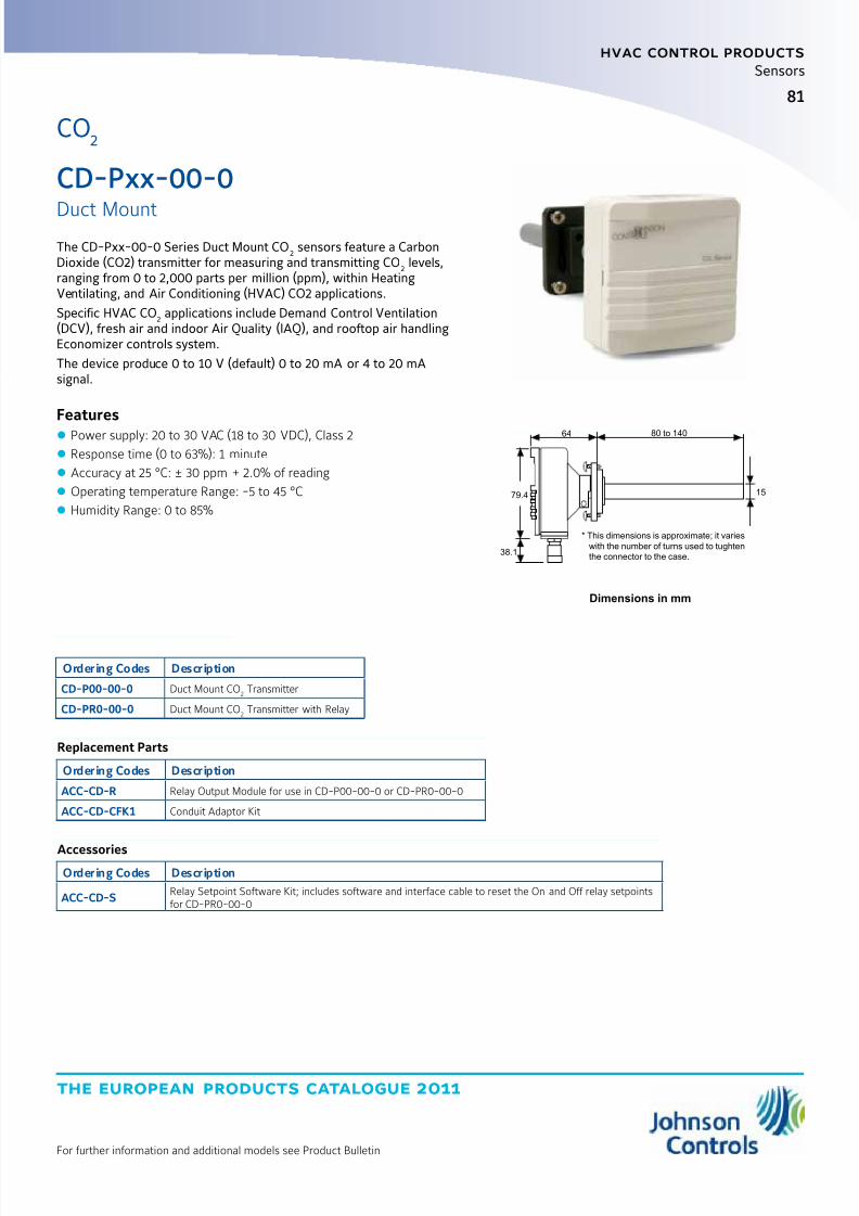
8/6/2019 Publ-6576 Prod Cat 11
http://slidepdf.com/reader/full/publ-6576-prod-cat-11 89/298
the european products catalogue 2011
For further information and additional models see Product Bulletin
hvac control products
81
Sensors
The CD-Pxx-00-0 Series Duct Mount CO2sensors feature a Carbon
Dioxide (CO2) transmitter for measuring and transmitting CO2levels,
ranging from 0 to 2,000 parts per million (ppm), within HeatingVentilating, and Air Conditioning (HVAC) CO2 applications.
Specific HVAC CO2applications include Demand Control Ventilation
(DCV), fresh air and indoor Air Quality (IAQ), and rooftop air handlingEconomizer controls system.
The device produce 0 to 10 V (default) 0 to 20 mA or 4 to 20 mAsignal.
Features z Power supply: 20 to 30 VAC (18 to 30 VDC), Class 2
z Response time (0 to 63%): 1 minute
z Accuracy at 25 °C: ± 30 ppm + 2.0% of reading
z Operating temperature Range: -5 to 45 °C
z Humidity Range: 0 to 85%
* This dimensions is approximate; it varies
with the number of turns used to tughten
the connector to the case.
64
79.4
38.1
15
80 to 140
Dimensions in mm
Ordering Codes Description
CD-P00-00-0 Duct Mount CO2Transmitter
CD-PR0-00-0 Duct Mount CO2Transmitter with Relay
Replacement Parts
Ordering Codes Description
ACC-CD-R Relay Output Module for use in CD-P00-00-0 or CD-PR0-00-0
ACC-CD-CFK1 Conduit Adaptor Kit
AccessoriesOrdering Codes Description
ACC-CD-SRelay Setpoint Software Kit; includes software and interface cable to reset the On and Off relay setpointsfor CD-PR0-00-0
CD-Pxx-00-0
Duct Mount
CO2

8/6/2019 Publ-6576 Prod Cat 11
http://slidepdf.com/reader/full/publ-6576-prod-cat-11 90/298
the european products catalogue 2011
hvac control products
82
For further information and additional models see Product Bulletin
Sensors
Dew Point
The HX-9100 Dew Sensor is used to prevent condensation on surfacessuch as cold water pipes, cool ceilings and windows.
The HX-9100 can be connected to Johnson Controls System controllersto provide override functions when condensation is forming.
Features z Supply voltage: 15 VDC ± 10%
z Action: ON/OFF or 0...10 VDC
z Hysteresis: 1%
z Output: open collector closed: 0.5 VDC max or ≤ + 0.5 VDC
z Protection class: IP44
HX-9000
Ordering Codes Action Output at Condensation Power Supply
HX-9100-8001 ON/OFF Open collector closed, 0.5 VDC max15 VDC ±10%
HX-9100-9001 0…10 VDC ≤ +0.5 VDC
lenght 1,5 m
lenght 1,5 m
50
1 0
1 5
Dimensions in mm

8/6/2019 Publ-6576 Prod Cat 11
http://slidepdf.com/reader/full/publ-6576-prod-cat-11 91/298
the european products catalogue 2011
For further information and additional models see Product Bulletin
hvac control products
83
Sensors
Humidity
The Johnson Controls HT-1000 series room humidity sensors provideactive sensing of relative humidity and, on specific models,also active/passive sensing of temperature in HVAC applications.
It features a polymer capacitance humidity sensing element andprovides within either ±2 % or ±4 % accuracy a voltage output signalproportional 0 to 100 % relative humidity.
The HT-1000 series room humidity sensors are designed for use withJohnson Controls System 91 and Facility Explorer controllers or forother systems having compatible input and output voltages.
Features z Supply voltage: 15 VDC ± 10%
z Action: ON/OFF or 0...10 VDC
z Hysteresis: 1%
z Output: open collector closed: 0.5 VDC max or ≤ + 0.5 VDC
z Protection class: IP44
HT-1000
Wall Mount
Ordering CodesHumidity
RangeHumidityOutput
HumidityAccuracy
TemperatureRange
TemperatureOutput
SupplyVoltage
HT-1201-UR
0…100% RH 0…10 VDC
±2% 0...40°C 0…10 VDC
12 to 30 VDC24 VAC ±15%
HT-1300-UR
±4%
--- ---
HT-1301-UR0...40°C
0…10 VDC
HT-1303-UR NTC K2
HT-1306-UR 0...60°C Pt1000
Dimensions in mm
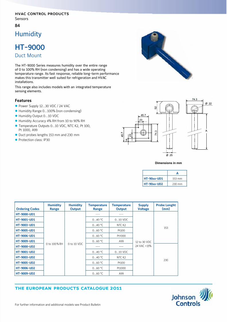
8/6/2019 Publ-6576 Prod Cat 11
http://slidepdf.com/reader/full/publ-6576-prod-cat-11 92/298
the european products catalogue 2011
hvac control products
84
For further information and additional models see Product Bulletin
Sensors
The HT-9000 Series measures humidity over the entire rangeof 0 to 100% RH (non condensing) and has a wide operatingtemperature range. Its fast response, reliable long-term performancemakes this transmitter well suited for refrigeration and HVACinstallations.
This range also includes models with an integrated temperaturesensing elements.
Features z Power Supply 12...30 VDC / 24 VAC
z
Humidity Range 0...100% (non condensing)z Humidity Output 0...10 VDC
z Humidity Accuracy 4% RH from 10 to 90% RH
z Temperature Outputs 0...10 VDC, NTC K2, Pt 100,Pt 1000, A99
z Duct probes lengths 153 mm and 230 mm
z Protection class: IP30
HT-9000
Duct Mount
Humidity
Ordering CodesHumidity
RangeHumidityOutput
TemperatureRange
TemperatureOutput
SupplyVoltage
Probe Lenght(mm)
HT-9000-UD1
0 to 100% RH 0 to 10 VDC
--- ---
12 to 30 VDC
24 VAC +15%
153
HT-9001-UD1 0…40 °C 0…10 VDC
HT-9003-UD1 0…40 °C NTC K2HT-9005-UD1 0…60 °C Pt100
HT-9006-UD1 0…60 °C Pt1000
HT-9009-UD1 0…60 °C A99
HT-9000-UD2 --- ---
230
HT-9001-UD2 0…40 °C 0…10 VDC
HT-9003-UD2 0…40 °C NTC K2
HT-9005-UD2 0…60 °C Pt100
HT-9006-UD2 0…60 °C Pt1000
HT-9009-UD2 0…60 °C A99
Dimensions in mm
A
HT-90xx-UD1 153 mm
HT-90xx-UD2 230 mm

8/6/2019 Publ-6576 Prod Cat 11
http://slidepdf.com/reader/full/publ-6576-prod-cat-11 93/298
the european products catalogue 2011
For further information and additional models see Product Bulletin
hvac control products
85
Sensors
The HT-9000 Series measures humidity over the entire rangeof 0 to 100% RH (non condensing) and has a wide operatingtemperature range. Its fast response, reliable long-term performancemakes this transmitter well suited for refrigeration and HVACinstallations.
This range also includes models with an integrated temperaturesensing element.
Features z Power Supply 12...30 VDC / 24 VAC
z
Humidity Range 0...100% (non condensing)z Humidity Output 0...10 VDC
z Humidity Accuracy 4% RH from 10 to 90% RH
z Temperature Outputs Pt 100 and A99
z Room enclosure 80 x 80 mm
z Protection Class: IP 30
HT-9000
Wall Mount
Humidity
Ordering Codes
Humidity
Range
Humidity
Output
Temperature
Range
Temperature
Output
Supply
Voltage
HT-9002-URW
0 to 100% RH 0...10 VDC 0…60 °C
0...10 VDC12 to 30 VDC
24 VAC ± 15 %HT-9005-URW Pt100
HT-9009-URW A99
31
8 1
81
Dimensions in mm

8/6/2019 Publ-6576 Prod Cat 11
http://slidepdf.com/reader/full/publ-6576-prod-cat-11 94/298
the european products catalogue 2011
hvac control products
86
For further information and additional models see Product Bulletin
Sensors
Pressure
DP2500
Differential PressureThe DP Low Differential Pressure Transmitter series is an accurate andcost competitive solution for measuring low pressures of airand non-aggressive gases in order to monitor and control pressures inbuilding automation, HVAC and clean room systems.
Features z Power Supply 24 VAC/VDC
z Pressure Range: 8 different ranges in one device (see the table)
z Output Signal: 0...10 VDC or 4...20 mA
z Automatically Autozero point adjusting
z Response time selectable z 4 digits display
z Protection Class: IP54
Ordering Codes Operating Range (Pa) Auto Zero Display Output Signal Enclosure Supply Voltage
DP2500-R8 *DP2500-R8-01 **
-100...+100
0...100
0...250
0...500
0...1000
0...1500
0...2000
0...2500
---
---
0...10 VDCor
4...20 mAIP54 24 VAC / VDC
DP2500-R8-AZ *DP2500-R8-AZ-01 **
DP2500-R8-D * ---
DP2500-R8-AZ-D *
DP0250-AZ * 0…100
0...250
---
DP0250-AZ-D *
DP0100-AZ *DP0100-AZ-01 ** -50...+50-100...+100
---
DP0100-AZ-D *
Note:* Single Package** Bulk Package
Dimensions in mm
DP
90.0 36.0
7 1 .
5
9 5 .
0
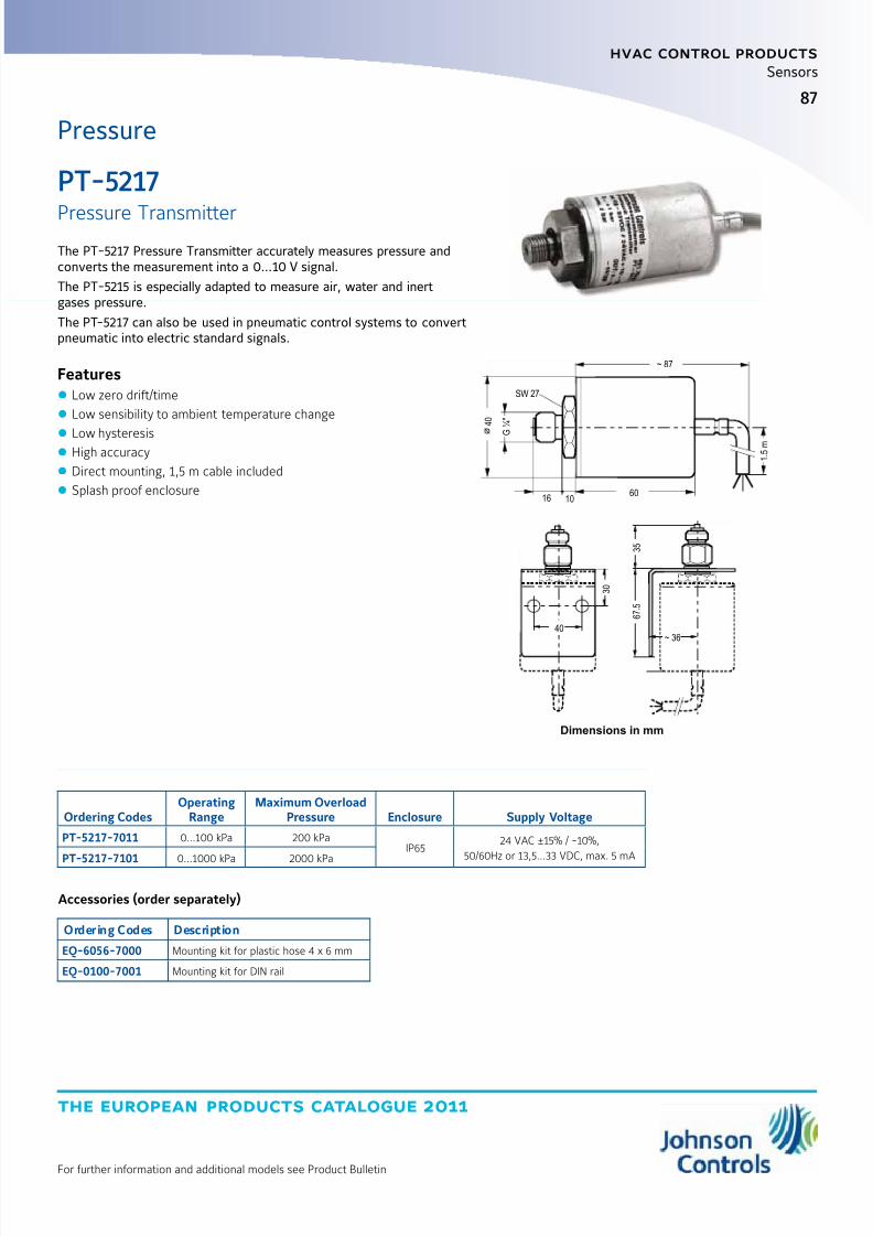
8/6/2019 Publ-6576 Prod Cat 11
http://slidepdf.com/reader/full/publ-6576-prod-cat-11 95/298
the european products catalogue 2011
For further information and additional models see Product Bulletin
hvac control products
87
Sensors
Pressure
PT-5217
Pressure TransmitterThe PT-5217 Pressure Transmitter accurately measures pressure andconverts the measurement into a 0...10 V signal.
The PT-5215 is especially adapted to measure air, water and inertgases pressure.
The PT-5217 can also be used in pneumatic control systems to convertpneumatic into electric standard signals.
Features z Low zero drift/time
z Low sensibility to ambient temperature change
z Low hysteresis z High accuracy
z Direct mounting, 1,5 m cable included
z Splash proof enclosure
Ordering CodesOperating
RangeMaximum Overload
Pressure Enclosure Supply Voltage
PT-5217-7011 0…100 kPa 200 kPaIP65
24 VAC ±15% / -10%,
50/60Hz or 13,5…33 VDC, max. 5 mAPT-5217-7101 0…1000 kPa 2000 kPa
Accessories (order separately)
Ordering Codes Description
EQ-6056-7000 Mounting kit for plastic hose 4 x 6 mm
EQ-0100-7001 Mounting kit for DIN rail
SW 27
4 0
G
¼ "
16 1060
~ 87
1 . 5 m
3 5
3 0
40
6 7 . 5
~ 36
Dimensions in mm

8/6/2019 Publ-6576 Prod Cat 11
http://slidepdf.com/reader/full/publ-6576-prod-cat-11 96/298
the european products catalogue 2011
hvac control products
88
For further information and additional models see Product Bulletin
Sensors
Dimensions in mm
Setpoint
adjustment
Mode LED
Mode selector
80 33
20
12
°C
28
24
80
TE-7000
Room Command ModuleThe TE-7000 Room Command Module is designed for use with theVMA1400 series VAV Modular Assembly.
The module has an NTC temperature sensor, a dial for setpointadjustment within the range of 12 to 28°C or -3 to +3K, and anoccupancy button with an LED indicator.
If the VAV controller is not already in occupied mode, as shown by theLED indicator, the occupant may press the occupancy button to obtaincomfort control for a set period of time, normally defaulted to onehour.
The module also has a built-in connector for a PC with the software totest and commission the VMA1400 series VAV Modular Assembly and
the air supply system.
Features z Power supply: Power from VMA1400
z Temperature sensor: NTC K2
z Occupancy Override button
z Protection Class: IP30
z Remote setpoint adjustment
Temperature
Accessories (order separately)
Ordering Codes Description
TE-7000-8900 Service tool connector cable (1.5 m) (for use with IU-9100 converter)
TM-9100-8900 Special tool (to open module)
TM-9100-8901 Dial-Stop screws kit (bag og 100 self-tapping screws)
TM-9100-8902 Serrated knob kit (bag of 10 knobs) - Off-white
TM-9100-8902-W Serrated knob kit (bag of 10 knobs) - white
Ordering Codes ColorSetpoint
Dial Range
TE-7000-8002 Off-White / Gray Base12 to 28 °C
TE-7000-8002-W White / White Base
TE-7000-8003 Off-White / Gray Base-3 to +3 K
TE-7000-8003-W White / White Base
NoteAdd “-K” to code for setpoint dial with serrated edge,e.g. TE-7000-8002-K, TE-7000-8002-WK
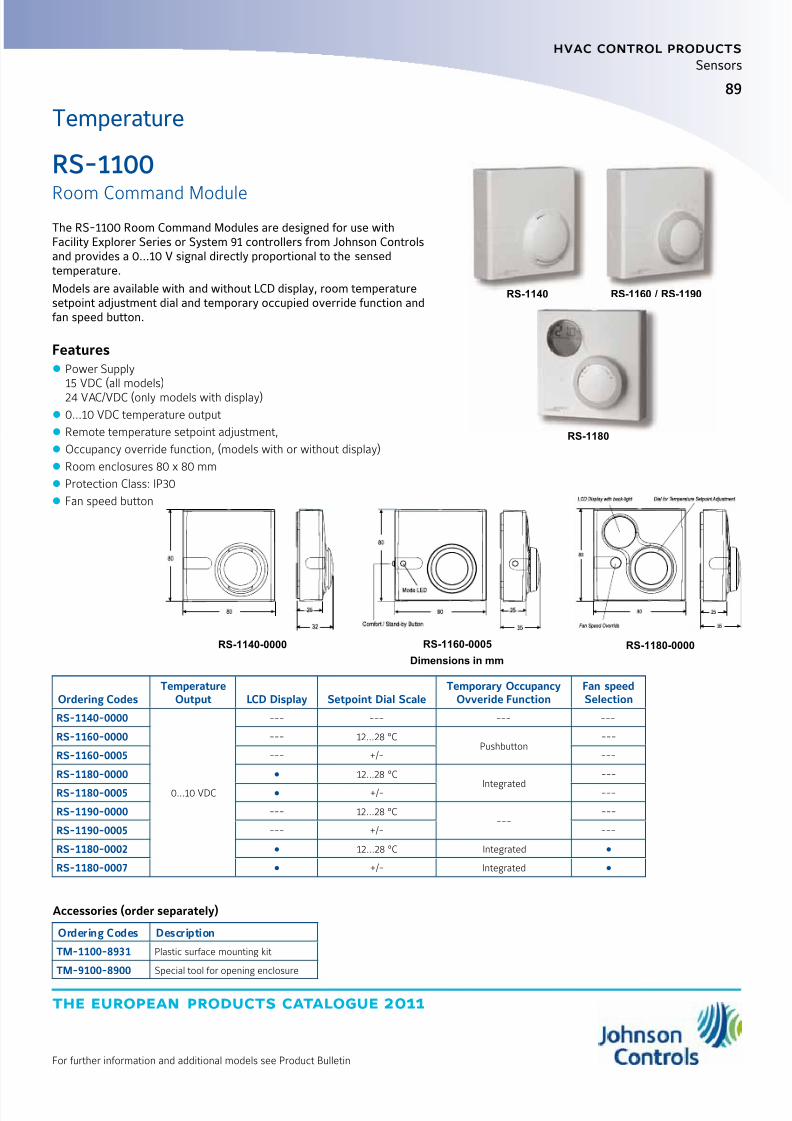
8/6/2019 Publ-6576 Prod Cat 11
http://slidepdf.com/reader/full/publ-6576-prod-cat-11 97/298
the european products catalogue 2011
For further information and additional models see Product Bulletin
hvac control products
89
Sensors
Temperature
RS-1100
Room Command ModuleThe RS-1100 Room Command Modules are designed for use withFacility Explorer Series or System 91 controllers from Johnson Controlsand provides a 0…10 V signal directly proportional to the sensedtemperature.
Models are available with and without LCD display, room temperaturesetpoint adjustment dial and temporary occupied override function andfan speed button.
Features z Power Supply15 VDC (all models)24 VAC/VDC (only models with display)
z 0...10 VDC temperature output
z Remote temperature setpoint adjustment,
z Occupancy override function, (models with or without display)
z Room enclosures 80 x 80 mm
z Protection Class: IP30
z Fan speed button
Accessories (order separately)
Ordering Codes Description
TM-1100-8931 Plastic surface mounting kit
TM-9100-8900 Special tool for opening enclosure
Ordering CodesTemperature
Output LCD Display Setpoint Dial ScaleTemporary Occupancy
Ovveride FunctionFan speedSelection
RS-1140-0000
0...10 VDC
--- --- --- ---
RS-1160-0000 --- 12...28 °CPushbutton
---
RS-1160-0005 --- +/- ---
RS-1180-0000 12...28 °C
Integrated
---
RS-1180-0005 +/- ---
RS-1190-0000 --- 12...28 °C---
---
RS-1190-0005 --- +/- ---
RS-1180-0002 12...28 °C Integrated
RS-1180-0007 +/- Integrated
RS-1180-0000RS-1160-0005
Dimensions in mm
RS-1140-0000
RS-1140
RS-1180
RS-1160 / RS-1190

8/6/2019 Publ-6576 Prod Cat 11
http://slidepdf.com/reader/full/publ-6576-prod-cat-11 98/298
the european products catalogue 2011
hvac control products
90
For further information and additional models see Product Bulletin
Sensors
Temperature
TM-1100
Room Command ModuleThe TM-1100 Series of Room Command Modules are designed foruse with the TC-9102, TC-9109 and TCU series of DDC terminal unitcontrollers.
The setpoint dial enables the room occupant to adjust the workingset point of the controller within the range of 12…28 °C or -3...+3°,according to the model number.
The occupancy button enables the occupant to switch the mode of operation of the controller between COMFORT and STANDBY or torequest a temporary COMFORT mode during NIGHT operation.
An LED indicator shows the current operating mode.For TC-9102 and TCU Fan Coil Unit controllers, a Room Command
Module with a 3-speed fan override is available. Models without atemperature sensing element are provided for application where thetemperature sensor is mounted inside the Fan Coil Unit.
Features z Passive Sensor
z NTC K2 Temperature Output
z Remote Temperature Setpoint adjustment
z 3-speed fan override
z Occupancy override button
z Room enclosures 80 x 80 mm
z IP 30
TM-1140-0000 TM-1160-0007 and TM-1170-0007
Ordering CodesBuilt-in Sensing
ElementTemperature
Setpoint Dial Scale Fan Speed OverrideOccupancy
Button
TM-1140-0000
NTC K2
---
---
---
TM-1150-0000
•
TM-1160-0000 12-28°C
TM-1160-0005 +/-
TM-1160-0002 12-28°C3-Speed Fan Override
TM-1160-0007
+/-TM-1170-0005Without
---
TM-1170-0007 3-Speed Fan Override
TM-1190-0000NTC K2
12-28°C--- ---
TM-1190-0005 +/-
Accessories (order separately)
Ordering Codes Description
TM-1100-8931 Plastic base for surface mount
TE-9100-8501 Unit Mount NTC K2 Temperature Sensor (1.5 m Cable)
TM-9100-8900 Special Tool for opening enclosure
Dimensions in mm
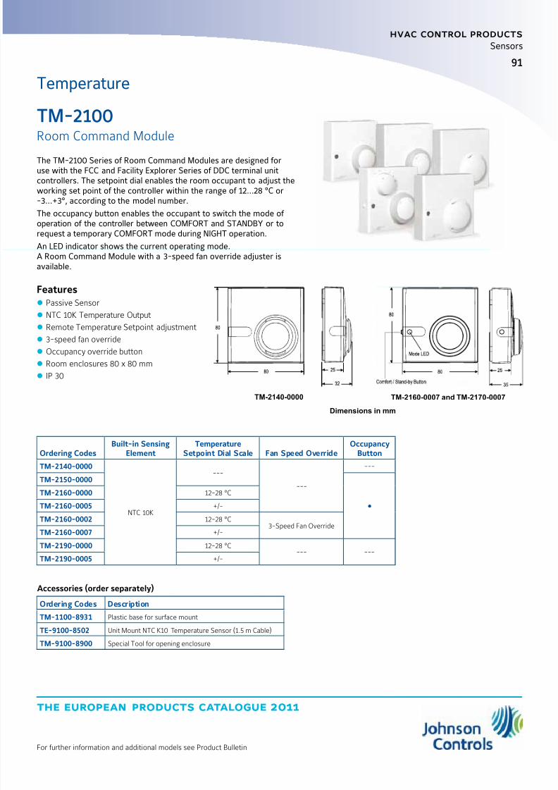
8/6/2019 Publ-6576 Prod Cat 11
http://slidepdf.com/reader/full/publ-6576-prod-cat-11 99/298
the european products catalogue 2011
For further information and additional models see Product Bulletin
hvac control products
91
Sensors
TM-2100
Room Command ModuleThe TM-2100 Series of Room Command Modules are designed foruse with the FCC and Facility Explorer Series of DDC terminal unitcontrollers. The setpoint dial enables the room occupant to adjust theworking set point of the controller within the range of 12…28 °C or-3...+3°, according to the model number.
The occupancy button enables the occupant to switch the mode of operation of the controller between COMFORT and STANDBY or torequest a temporary COMFORT mode during NIGHT operation.
An LED indicator shows the current operating mode.A Room Command Module with a 3-speed fan override adjuster isavailable.
Features z Passive Sensor
z NTC 10K Temperature Output
z Remote Temperature Setpoint adjustment
z 3-speed fan override
z Occupancy override button
z Room enclosures 80 x 80 mm
z IP 30
Temperature
Ordering CodesBuilt-in Sensing
ElementTemperature
Setpoint Dial Scale Fan Speed OverrideOccupancy
Button
TM-2140-0000
NTC 10K
---
---
---
TM-2150-0000
TM-2160-0000 12-28 °C
TM-2160-0005 +/-
TM-2160-0002 12-28 °C3-Speed Fan Override
TM-2160-0007 +/-
TM-2190-0000 12-28 °C
--- ---TM-2190-0005 +/-
Accessories (order separately)
Ordering Codes Description
TM-1100-8931 Plastic base for surface mount
TE-9100-8502 Unit Mount NTC K10 Temperature Sensor (1.5 m Cable)
TM-9100-8900 Special Tool for opening enclosure
TM-2140-0000 TM-2160-0007 and TM-2170-0007
Dimensions in mm

8/6/2019 Publ-6576 Prod Cat 11
http://slidepdf.com/reader/full/publ-6576-prod-cat-11 100/298
the european products catalogue 2011
hvac control products
92
For further information and additional models see Product Bulletin
Sensors
TM-3100
Room Command ModuleThe Johnson Controls TM-3100 Series Room Temperature Sensorprovide passive sensing of temperature in HVAC application.
The TM-3100 is equipped with a Pt1000 Class A sensing elementand provides an output proportional signal to the measured ambienttemperature.
The TM-3100 Series Room Temperature Sensor is designed foruse with the Facility Explorer Series and with the Field EquipmentController Series.
Features
z
Modern and attractive cover which snaps onto a plug-inmounting base
z Terminals located on mounting base.
z All models available with or without Occupancy override button
Temperature
Dimensions in mm
Accessories (order separately)
Ordering Codes Description
TM-1100-8931 Plastic base for surface mount
TM-9100-8900 Special Tool for opening enclosure
Ordering CodesBuilt-in Sensing
ElementTemperature
Setpoint Dial Scale Fan Speed OverrideOccupancy
Button
TM-3140-0000 Pt 1000 --- --- ---
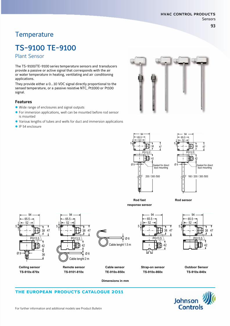
8/6/2019 Publ-6576 Prod Cat 11
http://slidepdf.com/reader/full/publ-6576-prod-cat-11 101/298
the european products catalogue 2011
For further information and additional models see Product Bulletin
hvac control products
93
Sensors
Temperature
TS-9100 TE-9100
Plant SensorThe TS-9100/TE-9100 series temperature sensors and transducersprovide a passive or active signal that corresponds with the airor water temperature in heating, ventilating and air conditioningapplications.
They provide either a 0…10 VDC signal directly proportional to thesensed temperature, or a passive resistive NTC, Pt1000 or Pt100signal.
Features z Wide range of enclosures and signal outputs
z
For immersion applications, well can be mounted before rod sensoris mounted
z Various lengths of tubes and wells for duct and immersion applications
z IP 54 enclosure
94
65.552
94
65.552
5 538 47 38 47
PG13.5 PG13.5
42 42
Ø 9 Ø 9Gasket for directduct mounting
Gasket for directduct mounting
200 / 300 /500 160 / 200 / 300 /500
Rod fast
response sensor
Rod sensor
94
65.552
5
38 47
PG13.5
94
65.552
5
38 47
PG13.5
42 42
Ø 9 36 Ø 6
Cable lenght 2 m
Ø 6
Cable lenght 1.5 m
94
65.552
5
38 47
PG13.5
42 42
94
65.552
5
38 47
PG13.5
Ceiling sensor
TS-910x-870x
Strap-on sensor
TS-910x-860x
Outdoor Sensor
TS-910x-840x
Remote sensor
TS-9101-810x
Cable sensor
TE-910x-850x
Dimensions in mm
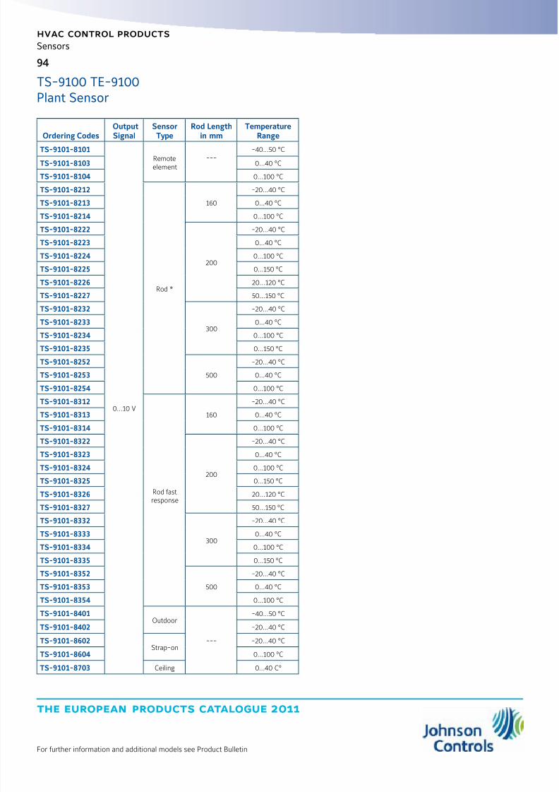
8/6/2019 Publ-6576 Prod Cat 11
http://slidepdf.com/reader/full/publ-6576-prod-cat-11 102/298
the european products catalogue 2011
hvac control products
94
For further information and additional models see Product Bulletin
Sensors
Ordering Codes
Output
Signal
Sensor
Type
Rod Length
in mm
Temperature
RangeTS-9101-8101
0...10 V
Remoteelement
----40...50 °C
TS-9101-8103 0...40 °C
TS-9101-8104 0...100 °C
TS-9101-8212
Rod *
160
-20...40 °C
TS-9101-8213 0...40 °C
TS-9101-8214 0...100 °C
TS-9101-8222
200
-20...40 °C
TS-9101-8223 0...40 °C
TS-9101-8224 0...100 °C
TS-9101-8225 0...150 °C
TS-9101-8226 20...120 °C
TS-9101-8227 50...150 °C
TS-9101-8232
300
-20...40 °C
TS-9101-8233 0...40 °C
TS-9101-8234 0...100 °C
TS-9101-8235 0...150 °C
TS-9101-8252
500
-20...40 °C
TS-9101-8253 0...40 °C
TS-9101-8254 0...100 °C
TS-9101-8312
Rod fastresponse
160
-20...40 °C
TS-9101-8313 0...40 °CTS-9101-8314 0...100 °C
TS-9101-8322
200
-20...40 °C
TS-9101-8323 0...40 °C
TS-9101-8324 0...100 °C
TS-9101-8325 0...150 °C
TS-9101-8326 20...120 °C
TS-9101-8327 50...150 °C
TS-9101-8332
300
-20...40 °C
TS-9101-8333 0...40 °C
TS-9101-8334 0...100 °C
TS-9101-8335 0...150 °C
TS-9101-8352
500
-20...40 °C
TS-9101-8353 0...40 °C
TS-9101-8354 0...100 °C
TS-9101-8401Outdoor
---
-40...50 °C
TS-9101-8402 -20...40 °C
TS-9101-8602Strap-on
-20...40 °C
TS-9101-8604 0...100 °C
TS-9101-8703 Ceiling 0...40 C°
TS-9100 TE-9100Plant Sensor
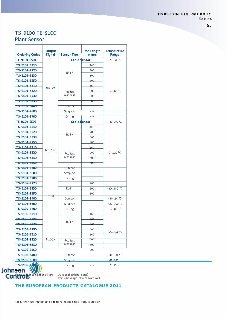
8/6/2019 Publ-6576 Prod Cat 11
http://slidepdf.com/reader/full/publ-6576-prod-cat-11 103/298
95
the european products catalogue 2011
hvac control products
For further information and additional models see Product Bulletin
Sensors
Ordering Codes
Output
Signal Sensor Type
Rod Length
in mm
Temperature
RangeTE-9100-8501
NTC K2
Cable Sensor -20...40 °C
TS-9103-8210
Rod *
160
0...40 °C
TS-9103-8220 200
TS-9103-8230 300
TS-9103-8250 500
TS-9103-8310
Rod fastresponse
160
TS-9103-8320 200
TS-9103-8330 300
TS-9103-8350 500
TS-9103-8400 Outdoor ---
TS-9103-8600 Strap-on ---TS-9103-8700 Ceiling ---
TE-9100-8502
NTC K10
Cable Sensor -20...40 °C
TS-9104-8210
Rod *
160
0...120 °C
TS-9104-8220 200
TS-9104-8230 300
TS-9104-8250 500
TS-9104-8310
Rod fastresponse
160
TS-9104-8320 200
TS-9104-8330 300
TS-9104-8350 500
TS-9104-8400 Outdoor ---
TS-9104-8600 Strap-on ---
TS-9104-8700 Ceiling ---
TS-9105-8220
Pt100
Rod *
200
-20...150 °CTS-9105-8230 300
TS-9105-8250 500
TS-9105-8400 Outdoor -40...50 °C
TS-9105-8600 Strap-on -20...100 °C
TS-9105-8700 Ceiling 0...40 °C
TS-9106-8210
Pt1000
Rod *
160
-20...150 °C
TS-9106-8220 200
TS-9106-8230 300
TS-9106-8250 500
TS-9106-8310
Rod fastresponse
160
TS-9106-8320 200
TS-9106-8330 300
TS-9106-8350 500
TS-9106-8400 Outdoor --- -40...50 °C
TS-9106-8600 Strap-on --- -20...100 °C
TS-9106-8700 Ceiling --- 0...40 °C
Note
* Rod sensor can either be for: - Duct applications (alone)
- Immersions applications (with well)
TS-9100 TE-9100Plant Sensor
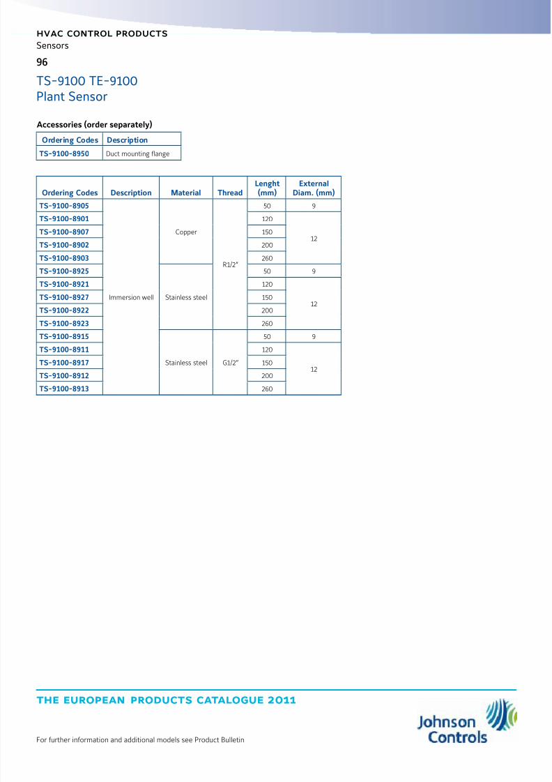
8/6/2019 Publ-6576 Prod Cat 11
http://slidepdf.com/reader/full/publ-6576-prod-cat-11 104/298
the european products catalogue 2011
hvac control products
96
For further information and additional models see Product Bulletin
Sensors
Ordering Codes Description Material ThreadLenght(mm)
ExternalDiam. (mm)
TS-9100-8905
Immersion well
Copper
R1/2”
50 9
TS-9100-8901 120
12TS-9100-8907 150
TS-9100-8902 200
TS-9100-8903 260
TS-9100-8925
Stainless steel
50 9TS-9100-8921 120
12TS-9100-8927 150
TS-9100-8922 200
TS-9100-8923 260
TS-9100-8915
Stainless steel G1/2”
50 9
TS-9100-8911 120
12TS-9100-8917 150
TS-9100-8912 200
TS-9100-8913 260
Accessories (order separately)
Ordering Codes Description
TS-9100-8950 Duct mounting flange
TS-9100 TE-9100Plant Sensor

8/6/2019 Publ-6576 Prod Cat 11
http://slidepdf.com/reader/full/publ-6576-prod-cat-11 105/298
the european products catalogue 2011
For further information and additional models see Product Bulletin
hvac control products
97
Sensors
WRS Many-to-One and TE-7800 One-to-One
Wireless SensorsThe WRS Many-to-One and TE-7800 One-to-One Wireless RoomTemperature Sensing System are designed to gather temperatureand zone data from multiple wireless room temperature sensors, anddistribute that data to multiple field controllers on a Metasys® network.
A Many-to-One WRS system consists of multiple WRS-TTx SeriesWireless Room Temperature Sensors communicating with one or moreWRS-RTN Series Receivers.
The receivers collect wireless temperature, zone, and battery-condition data messages and route that data over Ethernet to aNetwork Automation Engine (NAE) or a Network Control Engine (NCE).
The NAE or NCE distributes the temperature and zone data to
supported BACnet®, N2, and LonWorks® controllers on Metasysnetworks
A simple One-to-One wireless sensing system consists of oneWRS-TTx Series Wireless Room Temperature Sensor communicatingsingle-zone temperature data to an associated TE-7800 SeriesReceiver. Up to four sensors can report to a single receiver to provideenhanced zone control.
Features z Power supply: 24 VAC
z RF band: 2.4 GHZ ISM Bands
z Transmission Range: 114 m Max Indoor Line-of-Sight
50 m Practical Average Indoor z Transmissions: every 60 seconds
z Ambient operating Temperature: 0 to 50 °C
z Ambient operating Humidity: 0 to 95% RH
Temperature, Wireless
Ordering Codes DescriptionTransmission
Power
TE-7820-1
Receiver with Zone Bus Interface for One-to-One Wireless Room Temperature Sensing System, Interfaces with
VMA1400 Series Controllers (Only).Includes 1.8 m Zone Bus Interface Cable and Omnidirectional Antenna
10 dBm (CE Mark)
TE-7830-1
Receiver with Analog Interface for One-to-One Wireless Room Temperature Sensing System,Interfaces with Specified Analog Digital Controllers (Johnson Controls AS-AHU, AS-UNT, AS-VAV, DX-9100, or FXxxSeries Controllers).Includes 1.8 m Analog Interface Cable and Omnidirectional Antenna.
10 dBm (CE Mark)
WRS-RTN0000-1 Receiver for Many-to-One Wireless Room Temperature Sensing System, Includes Omnidirectional Antenna 10 dBm (CE Mark)
WRS-TTP0000-1 Wireless Room Temperature Sensor, Warmer/Cooler (+/-) Set Point Adjustment 10 dBm (CE Mark)
WRS-TTR0000-1 Wireless Room Temperature Sensor, No Set Point Adjustment 10 dBm (CE Mark)
WRS-TTS0000-1 Wireless Room Temperature Sensor, Set Point Adjustment Scale: 13 to 29°C 10 dBm (CE Mark)
80
120
Dimensions in mm

8/6/2019 Publ-6576 Prod Cat 11
http://slidepdf.com/reader/full/publ-6576-prod-cat-11 106/298
the european products catalogue 2011
Manufacturer reserved the rights to change specifications without prior notice
Notes

8/6/2019 Publ-6576 Prod Cat 11
http://slidepdf.com/reader/full/publ-6576-prod-cat-11 107/298
the european products catalogue 2011
Manufacturer reserved the rights to change specifications without prior notice
index
hvac control products
ThermostatsHardwired, Analogue
TC-8900 & PM-8900 Room Thermostat 101
Networked
TEC2000 Room Thermostat 103
TransducersElectro-Pneumatic Transducers
EP-1110 106
EP-2000 107
EP-8000 108

8/6/2019 Publ-6576 Prod Cat 11
http://slidepdf.com/reader/full/publ-6576-prod-cat-11 108/298
the european products catalogue 2011
Manufacturer reserved the rights to change specifications without prior notice
Notes

8/6/2019 Publ-6576 Prod Cat 11
http://slidepdf.com/reader/full/publ-6576-prod-cat-11 109/298
the european products catalogue 2011
For further information and additional models see Product Bulletin
hvac control products
101
Thermostats
TC-8900 is a family of analogue controllers designed for control of fancoils with 2-pipe, 2-pipe with change-over, 2-pipe with electrical coilor 4-pipe configurations.
For applications without fan speed control the family includes standalone units (TC-890x), local controllers (TC-893x) with remote setpointmodule (ES-8930) and local controllers (TC-894x) with central setpointmodule (ES-8940).
For applications with fan speed control the family includes thePM-8900 power modules in connection with TC-894x with or withoutcentral setpoint module (ES-8940).
Features z 2-pipe, 2-pipe with change-over, 2-pipe with electrical coil or 4-pipeconfigurations with and withoput 3-speed fan override
z 80 x 80 mm room enclosures
z Temperature dial ranges 12...28 °C, +/-
z 24 VAC power supply for the TC-8900 controls,230 VAC in connection the the PM-8900 power module
TC-8900 & PM-8900
Room Thermostat
Hardwired, Analogue
°C
Dimensions in mm
TC-890x Stand Alone Controllers
Ordering CodesBuilt-in NTC K10Sensing Element
SetpointRange
InputFan
Output
Outputs
0...10 V PAT 0...10 V DAT On/Off
TC-8903-1131-WK
12…28 °C
---
---
1 --- --- ---
TC-8901-2131-WK --- 2 --- ---
TC-8904-2131-WK --- --- 2 ---
TC-8906-2131-WK --- --- --- 2
TC-8903-1132-WK
---
1 --- --- ---
TC-8901-2132-WK --- 2 --- ---
TC-8904-2132-WK--- --- 2 ---
TC-8906-2132-WK --- --- --- 2
TC-8903-1151-WK 0…40 °C
1 --- --- ---
TC-8903-1152-WK
---
1 --- --- ---
TC-8903-1183-WK0…100%
1 --- --- ---
TC-8901-2183-WK --- 2 --- ---

8/6/2019 Publ-6576 Prod Cat 11
http://slidepdf.com/reader/full/publ-6576-prod-cat-11 110/298
the european products catalogue 2011
hvac control products
102
For further information and additional models see Product Bulletin
Thermostats
TC-8900 & PM-8900Room Thermostat
TC-893x Local Controllers with ES-8930-3031-WK remote setpoint module
Ordering CodesBuilt-in NTC K10Sensing Element
SetpointRange Fan Output
Outputs
PAT 0...10 V DAT On/Off
TC-8933-1112-W
--- ------
1 --- --- ---
TC-8931-2112-W --- 2 --- ---
TC-8934-2112-W --- --- 2 ---
TC-8936-2112-W --- --- --- 2
ES-8930-3031-WK 12…28 °C --- --- --- ---
TC-894x Local Controllers with ES-8940 central setpoint module
Ordering Codes
Built-in NTC K10
Sensing Element
Setpoint
Range Fan Output
Outputs
PAT 0...10 V DAT On/Off
TC-8943-1141-WK
+/----
1 --- --- ---
TC-8941-2141-WK --- 2 --- ---
TC-8944-2141-WK --- --- 2 ---
TC-8946-2141-WK --- --- --- 2
ES-8940-4130-WK --- 12…28 °C --- --- --- ---
TC-894x Local Controllers with ES-8940 central setpoint module
Ordering CodesBuilt-in NTC K10Sensing Element Setpoint Range
FanOutput Outputs
Power moduleOrdering Codes Configuration
TC-8902-1031-WK
12...28 °C
3 Speed
1 x 0...10 VDC1 x DAT 230 V1 x DAT 24 V
PM-8902-0500
PM-8905-0300
PM-8905-05002 pipe
with change over
TC-8907-1031-WK 1 x Relay 3A 230 V/24 V PM-8907-0300
TC-8902-2031-WK
2 x 0...10 VDC2 x DAT 230 V2 x DAT 24 V
PM-8902-0500
PM-8905-0300
PM-8905-0500 4 pipe
TC-8907-2031-WK 2 x Relay 3A 230 V/24 V PM-8907-0300
TC-8902-1032-WK
---
1 x 0...10 VDC1 x DAT 230 V1 x DAT 24 V
PM-8902-0500
PM-8905-0300
PM-8905-05002 pipe
with change over
TC-8907-1032-WK 1 x Relay 3A 230 V/24 V PM-8907-0300
TC-8902-2032-WK
2 x 0...10 VDC2 x DAT 230 V
2 x DAT 24 V
PM-8902-0500
PM-8905-0300
PM-8905-0500
4 pipe
TC-8907-2032-WK 2 x Relay 3A 230 V/24 V PM-8907-0300
TC-8942-2041-WK(only in connection withES-8940-4130-WK)
+/- on local controller TC-89,12...28 °C on ES-8940
central setpoint module
2 x 0...10 VDC2 x DAT 230 V2 x DAT 24 V
PM-8902-0500
PM-8905-0300
PM-8905-0500
TC-8947-2041-WK(only in connection withES-8940-4130-WK)
2 x Relay 3A 230 V/24 V PM-8907-0300
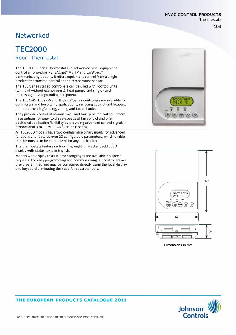
8/6/2019 Publ-6576 Prod Cat 11
http://slidepdf.com/reader/full/publ-6576-prod-cat-11 111/298
the european products catalogue 2011
For further information and additional models see Product Bulletin
hvac control products
103
Thermostats
The TEC2000 Series Thermostat is a networked small equipmentcontroller providing N2, BACnet® MS/TP and LonWorks
® communicating options. It offers equipment control from a singleproduct: thermostat, controller and temperature sensor.
The TEC Series staged controllers can be used with rooftop units(with and without economizers), heat pumps and single- andmulti-stage heating/cooling equipment.
The TEC2x45, TEC2xx6 and TEC2xx7 Series controllers are available forcommercial and hospitality applications, including cabinet unit heaters,perimeter heating/cooling, zoning and fan coil units.
They provide control of various two- and four-pipe fan coil equipment,
have options for one- to three-speeds of fan control and offeradditional application flexibility by providing advanced control signals –proportional 0 to 10 VDC, ON/OFF, or Floating.
All TEC2000 models have two configurable binary inputs for advancedfunctions and features over 20 configurable parameters, which enablethe thermostat to be customized for any application.
The thermostats features a two-line, eight-character backlit LCDdisplay with status texts in English.
Models with display texts in other languages are available on specialrequests. For easy programming and commissioning, all controllers arepre-programmed and may be configured directly using the local displayand keyboard eliminating the need for separate tools.
TEC2000
Room Thermostat
Networked
NO YES
21.5 °C
86
125
29
Room Temp
Dimensions in mm
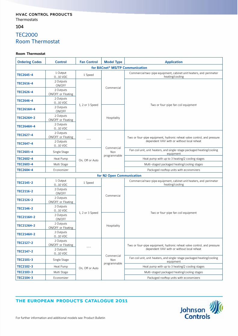
8/6/2019 Publ-6576 Prod Cat 11
http://slidepdf.com/reader/full/publ-6576-prod-cat-11 112/298
the european products catalogue 2011
hvac control products
104
For further information and additional models see Product Bulletin
Thermostats
TEC2000Room Thermostat
Room Thermostat
Ordering Codes Control Fan Control Model Type Application
for BACnet® MS/TP Communication
TEC2645-41 Output
0...10 VDC1 Speed
Commercial
Commercial two-pipe equipment, cabinet unit heaters, and perimeterheating/cooling
TEC2616-42 Outputs
ON/OFF
1, 2 or 3 Speed Two or four-pipe fan coil equipment
TEC2626-42 Outputs
ON/OFF or Floating
TEC2646-42 Outputs
0...10 VDC
TEC2616H-42 Outputs
ON/OFF
HospitalityTEC2626H-2
2 Outputs
ON/OFF or Floating
TEC2646H-42 Outputs
0...10 VDC
TEC2627-42 Outputs
ON/OFF or Floating---
Commercial
Nonprogrammable
Two or four-pipe equipment, hydronic reheat valve control, and pressuredependent VAV with or without local reheat
TEC2647-42 Outputs
0...10 VDC
TEC2601-4 Single Stage
On, Off or Auto
Fan coil unit, unit heaters, and single-stage packaged heating/coolingequipment
TEC2602-4 Heat Pump Heat pump with up to 3 heating/2 cooling stages
TEC2603-4 Multi Stage Multi-staged packaged heating/cooling stages
TEC2604-4 Economizer Packaged rooftop units with economizers
for N2 Open Communication
TEC2145-21 Output
0...10 VDC1 Speed
Commercial
Commercial two-pipe equipment, cabinet unit heaters, and perimeterheating/cooling
TEC2116-22 Outputs
ON/OFF
1, 2 or 3 Speed Two or four-pipe fan coil equipment
TEC2126-22 Outputs
ON/OFF or Floating
TEC2146-22 Outputs
0...10 VDC
TEC2116H-22 Outputs
ON/OFF
HospitalityTEC2126H-22 Outputs
ON/OFF or Floating
TEC2146H-22 Outputs
0...10 VDC
TEC2127-22 Outputs
ON/OFF or Floating---
Commercial
Nonprogrammable
Two or four-pipe equipment, hydronic reheat valve control, and pressuredependent VAV with or without local reheat
TEC2147-22 Outputs
0...10 VDC
TEC2101-3 Single Stage
On, Off or Auto
Fan coil unit, unit heaters, and single-stage packaged heating/coolingequipment
TEC2102-3 Heat Pump Heat pump with up to 3 heating/2 cooling stages
TEC2103-3 Multi Stage Multi-staged packaged heating/cooling stages
TEC2104-3 Economizer Packaged rooftop units with economizers
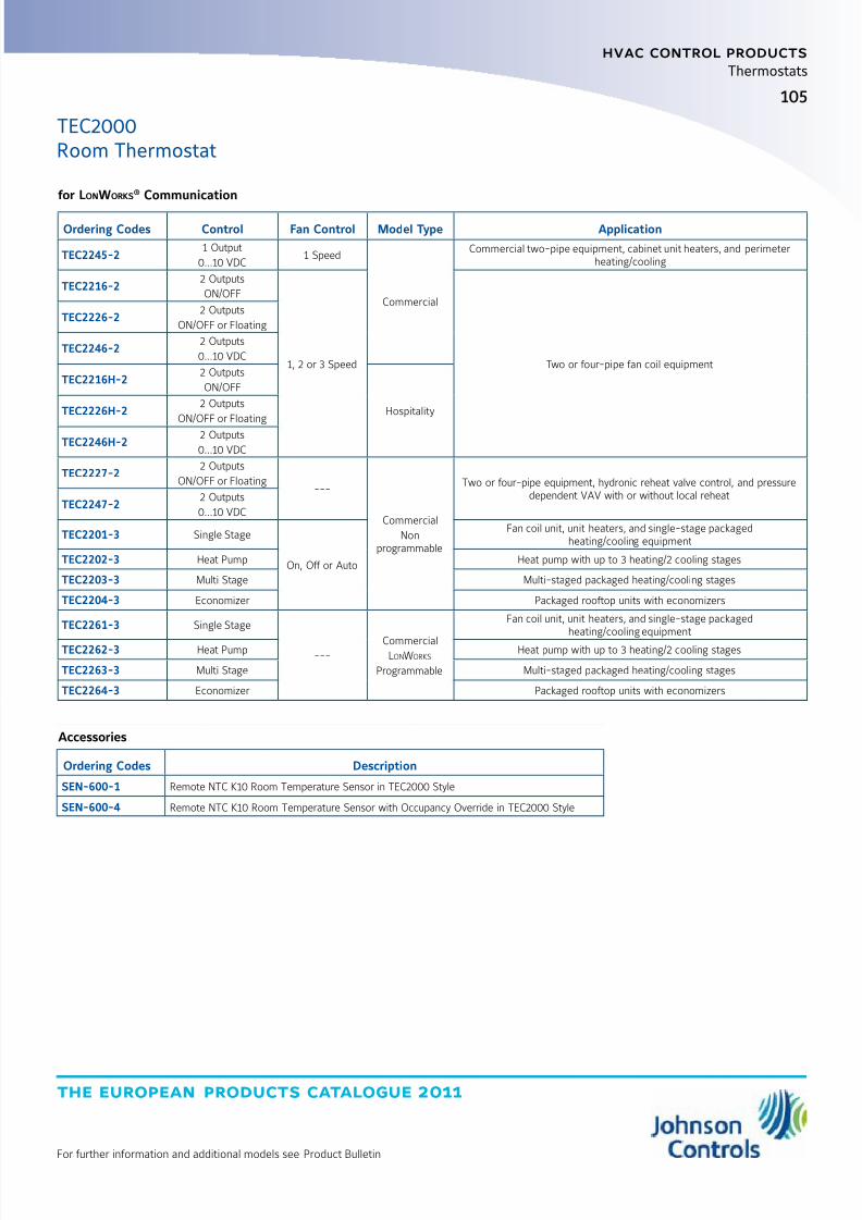
8/6/2019 Publ-6576 Prod Cat 11
http://slidepdf.com/reader/full/publ-6576-prod-cat-11 113/298
105
the european products catalogue 2011
hvac control products
For further information and additional models see Product Bulletin
Thermostats
for LONWORKS® Communication
Ordering Codes Control Fan Control Model Type Application
TEC2245-21 Output
0...10 VDC1 Speed
Commercial
Commercial two-pipe equipment, cabinet unit heaters, and perimeterheating/cooling
TEC2216-22 Outputs
ON/OFF
1, 2 or 3 Speed Two or four-pipe fan coil equipment
TEC2226-22 Outputs
ON/OFF or Floating
TEC2246-22 Outputs
0...10 VDC
TEC2216H-22 Outputs
ON/OFF
HospitalityTEC2226H-22 Outputs
ON/OFF or Floating
TEC2246H-22 Outputs
0...10 VDC
TEC2227-22 Outputs
ON/OFF or Floating---
Commercial
Nonprogrammable
Two or four-pipe equipment, hydronic reheat valve control, and pressuredependent VAV with or without local reheat
TEC2247-22 Outputs
0...10 VDC
TEC2201-3 Single Stage
On, Off or Auto
Fan coil unit, unit heaters, and single-stage packagedheating/cooling equipment
TEC2202-3 Heat Pump Heat pump with up to 3 heating/2 cooling stages
TEC2203-3 Multi Stage Multi-staged packaged heating/cooling stages
TEC2204-3 Economizer Packaged rooftop units with economizers
TEC2261-3 Single Stage
---CommercialLonWorks
Programmable
Fan coil unit, unit heaters, and single-stage packagedheating/cooling equipment
TEC2262-3 Heat Pump Heat pump with up to 3 heating/2 cooling stages
TEC2263-3 Multi Stage Multi-staged packaged heating/cooling stages
TEC2264-3 Economizer Packaged rooftop units with economizers
Accessories
Ordering Codes Description
SEN-600-1 Remote NTC K10 Room Temperature Sensor in TEC2000 Style
SEN-600-4 Remote NTC K10 Room Temperature Sensor with Occupancy Override in TEC2000 Style
TEC2000Room Thermostat
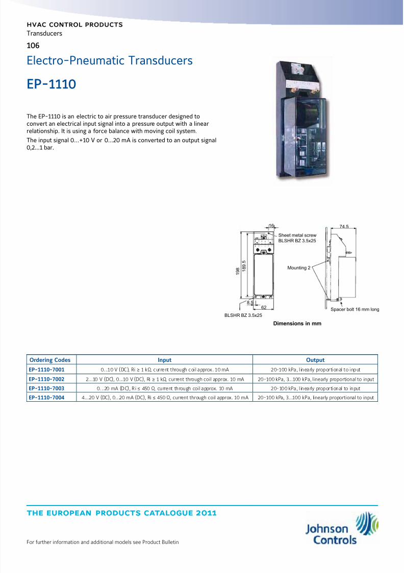
8/6/2019 Publ-6576 Prod Cat 11
http://slidepdf.com/reader/full/publ-6576-prod-cat-11 114/298
the european products catalogue 2011
hvac control products
106
For further information and additional models see Product Bulletin
Transducers
Electro-Pneumatic Transducers
1 9 8
1 8 9 .
5
8.562
BLSHR BZ 3.5x25
Mounting 2
Spacer bolt 16 mm long
74.5
Sheet metal screw
BLSHR BZ 3.5x25
16
Ordering Codes Input Output
EP-1110-7001 0...10 V (DC), Ri ≥ 1 kΩ, current through coil approx. 10 mA 20-100 kPa, l inearly proportional to input
EP-1110-7002 2...10 V (DC), 0...10 V (DC), Ri ≥ 1 kΩ, current through coil approx. 10 mA 20-100 kPa, 3...100 kPa, linearly proportional to input
EP-1110-7003 0...20 mA (DC), Ri ≤ 450 Ω, current through coil approx. 10 mA 20-100 kPa, l inearly proportional to input
EP-1110-7004 4...20 V (DC), 0...20 mA (DC), Ri ≤ 450 Ω, current through coil approx. 10 mA 20-100 kPa, 3...100 kPa, linearly proportional to input
Dimensions in mm
The EP-1110 is an electric to air pressure transducer designed toconvert an electrical input signal into a pressure output with a linearrelationship. It is using a force balance with moving coil system.
The input signal 0...+10 V or 0...20 mA is converted to an output signal0,2...1 bar.
EP-1110
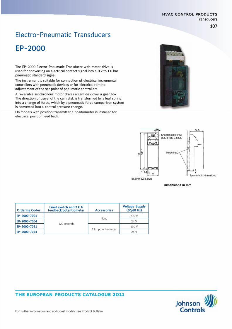
8/6/2019 Publ-6576 Prod Cat 11
http://slidepdf.com/reader/full/publ-6576-prod-cat-11 115/298
the european products catalogue 2011
For further information and additional models see Product Bulletin
hvac control products
107
Transducers
1 9 8
1 8 9 .
5
8.5 62
BLSHR BZ 3.5x25
Mounting 2
Spacer bolt 16 mm long
74.5
Sheet metal screw
BLSHR BZ 3.5x25
16
Dimensions in mm
Ordering CodesLimit switch and 2 k Ω
feedback potentiometer AccessoriesVoltage Supply
(50/60 Hz)
EP-2000-7001
120 seconds
None230 V
EP-2000-7004 24 V
EP-2000-7021
2 kΩ potentiometer
230 V
EP-2000-7024 24 V
The EP-2000 Electro-Pneumatic Transducer with motor drive isused for converting an electrical contact signal into a 0.2 to 1.0 barpneumatic standard signal.
The instrument is suitable for connection of electrical incrementalcontrollers with pneumatic devices or for electrical remoteadjustement of the set point of pneumatic controllers.
A reversible synchronous motor drives a cam disk over a gear box.The direction of travel of the cam disk is transformed by a leaf springinto a change of force, which by a pneumatic force comparison systemis converted into a control pressure change.
On models with position transmitter a positiometer is installed for
electrical position feed back.
EP-2000
Electro-Pneumatic Transducers
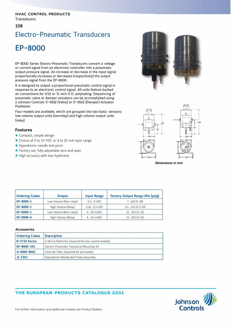
8/6/2019 Publ-6576 Prod Cat 11
http://slidepdf.com/reader/full/publ-6576-prod-cat-11 116/298
the european products catalogue 2011
hvac control products
108
For further information and additional models see Product Bulletin
Transducers
EP-8000 Series Electro-Pneumatic Transducers convert a voltageor current signal from an electronic controller into a pneumaticoutput pressure signal. An increase or decrease in the input signalproportionally increases or decreases (respectively) the outputpressure signal from the EP-8000.
It is designed to output a proportional pneumatic control signal inresponse to an electronic control signal. All units feature barbedair connections for 5/32 or ¼ inch O.D. polytubing. Sequencing of pneumatic valve or damper actuators can be accomplished usinga Johnson Controls V-9502 (Valve) or D-9502 (Damper) ActuatorPositioner.
Four models are available, which are grouped into two basic versions:
low volume output units (nonrelay) and high volume output units(relay).
Features z Compact, simple design
z Choice of 0 to 10 VDC or 4 to 20 mA input range
z Hypodermic needle test point
z Factory set, fully adjustable zero and span
z High accuracy with low hysteresis
EP-8000
5°5°
85
38
45
48
51
60
48
51
60
S O
5°5°
108
61
45
Dimensions in mm
Ordering Codes Output Input Range Factory Output Range kPa (psig)
EP-8000-1 Low Volume (Non-relay) 0.5...9 VDC 7...126 (1-18)
EP-8000-2 High Volume (Relay) 0.25...9.5 VDC 3.5...133 (0.5-19)
EP-8000-3 Low Volume (Non-relay) 4...20 mADC 21...105 (3-15)
EP-8000-4 High Volume (Relay) 4...20 mADC 21...105 (3-15)
Accessories
Ordering Codes Description
R-3710 Series 0.18 mm Restrictor (required for low volume models)
EP-8000-101 Electro-Pneumatic Transducer Mounting Kit
A-4000-8001 Inline Air Filter (required for all models)
JC 5361 Hypodermic Needle test Probe Assembly
Electro-Pneumatic Transducers
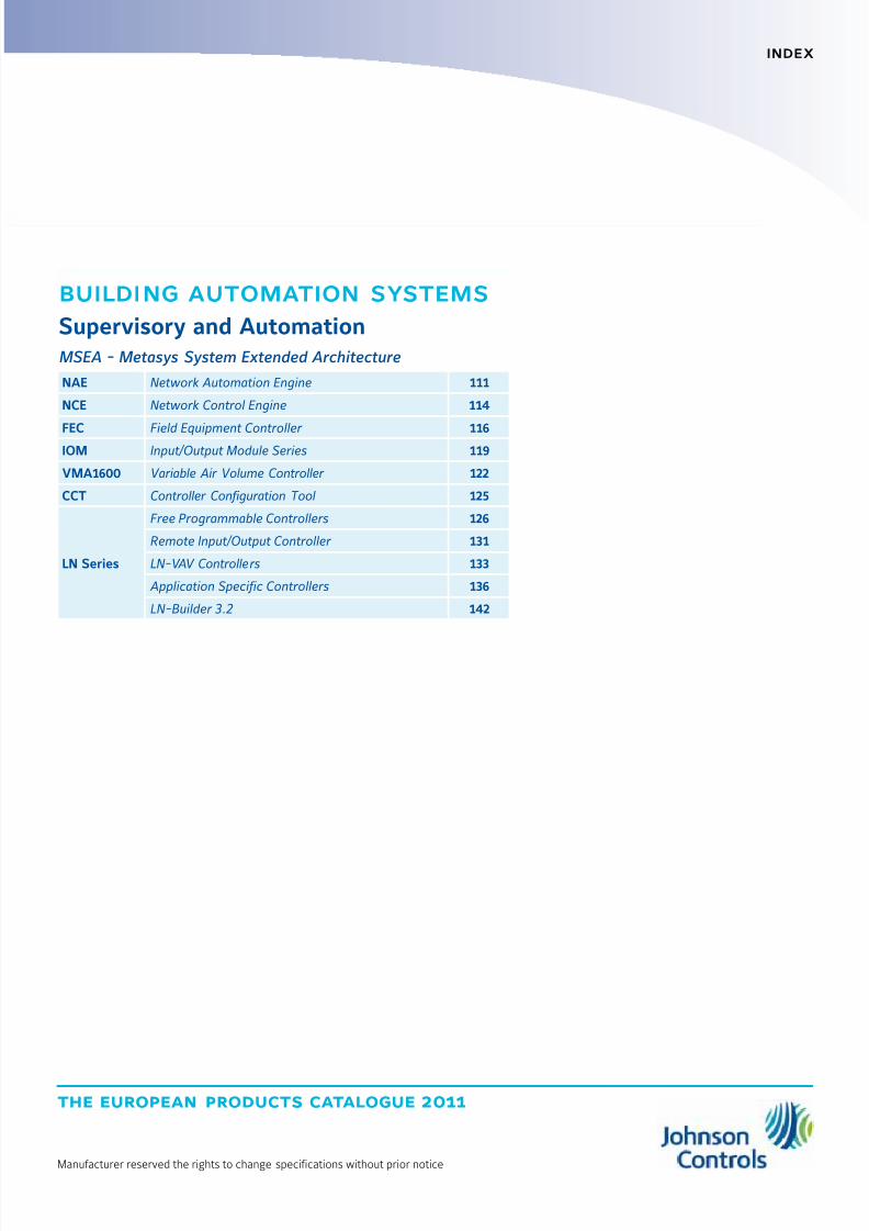
8/6/2019 Publ-6576 Prod Cat 11
http://slidepdf.com/reader/full/publ-6576-prod-cat-11 117/298
the european products catalogue 2011
Manufacturer reserved the rights to change specifications without prior notice
index
building automation systems
Supervisory and AutomationMSEA - Metasys System Extended Architecture
NAE Network Automation Engine 111
NCE Network Control Engine 114
FEC Field Equipment Controller 116IOM Input/Output Module Series 119
VMA1600 Variable Air Volume Controller 122
CCT Controller Configuration Tool 125
LN Series
Free Programmable Controllers 126
Remote Input/Output Controller 131
LN-VAV Controllers 133
Application Specific Controllers 136
LN-Builder 3.2 142

8/6/2019 Publ-6576 Prod Cat 11
http://slidepdf.com/reader/full/publ-6576-prod-cat-11 118/298
the european products catalogue 2011
Manufacturer reserved the rights to change specifications without prior notice
Notes

8/6/2019 Publ-6576 Prod Cat 11
http://slidepdf.com/reader/full/publ-6576-prod-cat-11 119/298
the european products catalogue 2011
For further information and additional models see Product Installation Guide
111
building automation systems
111
Supervisory and Automation
MSEA - Metasys® System Extended Architecture
NAE
Network Automation EngineNetwork Automation Engines (NAEs) enable Internet Protocol (IP)connectivity and Web-based access to Metasys® Building ManagementSystems (BMSs).
NAEs leverage standard building management communicationtechnologies, including BACnet® protocol, LonWorks
® network, andN2 Bus protocol to monitor and supervise a wide variety of Heating,Ventilating, and Air Conditioning (HVAC); lighting; security; fire; andaccess control equipment.
NAEs provide comprehensive equipment monitoring and control,scheduling, alarm and event management, energy management, dataexchange, data trending, and data storage.
NAEs feature an embedded Site Management Portal user interface,support multiple concurrent Web browser sessions with passwordand permission access control, and provide the protection of industrystandard Information Technology (IT) security.
NAE55 models support a comprehensive set of supervisory featuresand functions for large facilities and technically advanced buildings andcomplexes.
The NAE35/NAE45 models enable cost-effective NAE connectivity andcontrol in smaller facilities, and can extend NAE supervisory functionsin larger facilities.
The NAE85 is a high-capacity NAE that allows integration of largeBACnet IP systems and can take the place of multiple NAEs.
Features z Communication Using Commonly Accepted IT Standards at theAutomation and Enterprise Level
z Web-Based User Interface
z Site Director Function
z Support for Web Services at the Automation Network Level
z User Interface and Online System Configuration Software Embeddedin NAE
z Supervision of Field Controller Networks Including BACnet MS/TP,N2 Bus, LonWorks Network, and BACnet IP Devices
z Multiple Connection Options for Data Access
NAE55 Network Automation Engine
NAE45 Network Automation Engine
NAE85 Network Automation Engine

8/6/2019 Publ-6576 Prod Cat 11
http://slidepdf.com/reader/full/publ-6576-prod-cat-11 120/298
the european products catalogue 2011
For further information and additional models see Product Installation Guide
112
building automation systems
Supervisory and Automation
NAENetwork Automation Engine
NAE35
Ordering Codes Description
MS-NAE35xx-xxx(Base Features of Each NAE35)
NAE35 Network Automation Engines: Requires a 24 VAC power supply. Each model includes one RS-232-C serial port,one USB serial port, one Ethernet port, and an MS-BAT1020-0 Data Protection Battery.
MS-NAE3510-2Supports one N2 or BACnet MS/TP (RS-485) trunk; includes an additional RS-232-C serial port for optional external modem;supports up to 50 devices on the N2 or BACnet MS/TP trunk.
MS-NAE3510-2USupports one N2 or BACnet MS/TP (RS-485) trunk; includes an additional RS-232-C serial port for optional external modem;supports up to 50 devices on the N2 or BACnet MS/TP trunk.
Note: This model is UL Listed, File S4977, UUKL 864 - 9th Edition Smoke Control Equipment.
MS-NAE3511-2Supports one N2 or BACnet MS/TP (RS-485) trunk (RS-485 port); includes an internal modem;supports up to 50 devices on the N2 or BACnet MS/TP trunk.
MS-NAE3514-2Supports one N2 or BACnet MS/TP (RS-485) trunk; features Basic Access support; includes an additional RS-232-C serial port foroptional external modem; supports up to 50 devices on the N2 or BACnet MS/TP trunk.
MS-NAE3515-2Supports one N2 or BACnet MS/TP (RS-485) trunk; features Basic Access support; includes an internal modem;
supports up to 50 devices on the N2 or BACnet MS/TP trunk.
MS-NAE3520-2Supports one LonWorks trunk, includes an additional RS-232-C serial port for optional external modem.Supports up to 64 devices on the LonWorks port.
MS-NAE3520-2USupports one LonWorks trunk, includes an additional RS-232-C serial port for optional external modem.Supports up to 64 devices on the LonWorks port.
Note: This model is UL Listed, File S4977, UUKL 864 - 9th Edition Smoke Control Equipment.
MS-NAE3521-2 Supports one LonWorks trunk, includes an internal modem. Supports up to 64 devices on the LonWorks port.
MS-NAE3524-2Supports one LonWorks trunk, features Basic Access support, and includes an additional RS-232-C serial portfor optional external modem. Supports up to 64 devices on the LonWorks trunks.
MS-NAE3525-2Supports one LonWorks trunk, features Basic Access support, and includes an internal modem.Supports up to 64 devices on the LonWorks trunks.
Note:For repair parts, add -702 after the code number.
NAE45
Ordering Codes Description
MS-NAE45xx-xxx(Base Features of Each NAE45)
NAE45 Network Automation Engines: Requires a 24 VAC power supply. Each model includes one RS-232-C serial port,one USB serial port, one Ethernet port, and an MS-BAT1020-0 Data Protection Battery.
MS-NAE4510-2Supports one N2 or BACnet MS/TP (RS-485) trunk; includes an additional RS-232-C serial port for optional external modem;supports up to 100 devices on the N2 or BACnet MS/TP trunk.
MS-NAE4510-2USupports one N2 or BACnet MS/TP (RS-485) trunk; includes an additional RS-232-C serial port for optional external modem; supportsup to 100 devices on the N2 or BACnet MS/TP trunk.
Note: This model is UL Listed, File S4977, UUKL 864 - 9th Edition Smoke Control Equipment.
MS-NAE4511-2Supports one N2 or BACnet MS/TP (RS-485) trunk; includes an internal modem; supports up to 100 deviceson the N2 or BACnet MS/TP trunk.
MS-NAE4520-2Supports one LonWorks trunk, includes an additional RS-232-C serial port for optional external modem;
supports up to 127 devices on the Lon
Works
port.
MS-NAE4520-2USupports one LonWorks trunk, includes an additional RS-232-C serial port for optional external modem;supports up to 127 devices on the LonWorks port.
Note: This model is UL Listed, File S4977, UUKL 864 - 9th Edition Smoke Control Equipment.
MS-NAE4521-2 Supports one LonWorks trunk, includes an internal modem; supports up to 127 devices on the LonWorks port.
Note:For repair parts, add -702 after the code number.
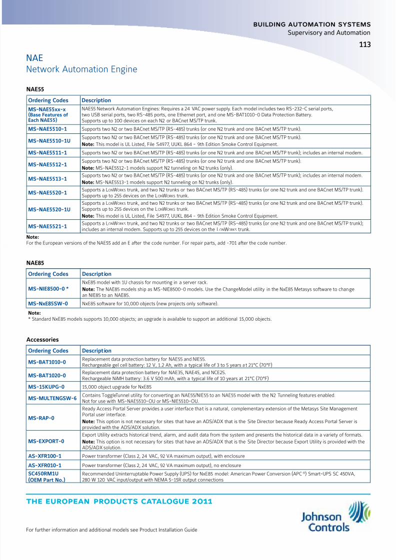
8/6/2019 Publ-6576 Prod Cat 11
http://slidepdf.com/reader/full/publ-6576-prod-cat-11 121/298

8/6/2019 Publ-6576 Prod Cat 11
http://slidepdf.com/reader/full/publ-6576-prod-cat-11 122/298
the european products catalogue 2011
For further information and additional models see Product Installation Guide
building automation systems
114
Supervisory and Automation
MSEA - Metasys® System Extended Architecture
NCE
Network Control EngineThe Metasys® Network Control Engine (NCE) Series controllers combinethe network supervisor capabilities and Internet Protocol (IP) networkconnectivity of a Network Automation Engine (NAE) with the Input/Output (I/O) point connectivity and direct digital control capabilitiesof a Field Equipment Controller (FEC). NCEs provide a cost-effectivesolution designed for integrating central plants and large built-up airhandlers into your Metasys networks.
All NCE models provide IP Ethernet network connectivity, theMetasys Site Management Portal User Interface (UI), and the networksupervisory capabilities featured on NAE35/NAE45 Series networkautomation engines.
All NCE models provide connectivity to and supervisory control of aspecified field bus trunk with up to 32 field controllers. Depending onthe model, an NCE25 supports either a BACnet® Master-Slave/Token-Passing (MS/TP) trunk, an N2 Bus trunk, or a LonWorks
® network trunk.
All NCE models feature 33 integral I/O points and a Sensor Actuator(SA) Bus, which allow you to increase the NCE’s I/O field point capacityand also integrate NS Series Network Sensors and Variable FrequencyDrives (VFDs) into your NCE application.
Some NCE models feature an integral field controller display screenwith a navigation keypad. In addition, some NCE models feature aninternal modem that supports standard dial-up capabilities.
Features z Uses Commonly Accepted Information Technology (IT) Standards atthe Automation and Enterprise Level
z Web-Based User Interface
z Supervision of Either an N2 Bus, LonWorks Network, or BACnet MS/TPBus Field Controller Trunk
z Multiple Connection Options for Data Access
z Integral Field Controller with 33 I/O Points
z Expandable I/O Point Capacity, NS Sensor Connectivity, and VFDControl on Field Controller SA Bus
NCE25 Network Control Engine
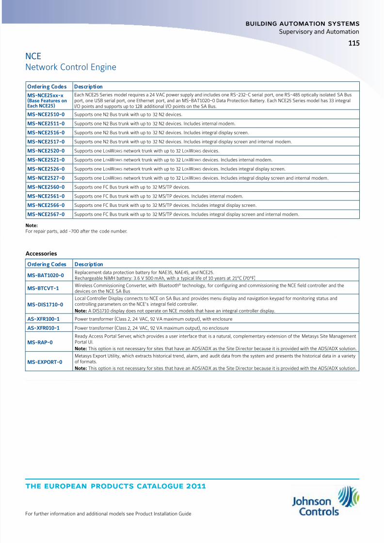
8/6/2019 Publ-6576 Prod Cat 11
http://slidepdf.com/reader/full/publ-6576-prod-cat-11 123/298
the european products catalogue 2011
For further information and additional models see Product Installation Guide
115
building automation systems
Supervisory and Automation
NCENetwork Control Engine
Ordering Codes Description
MS-NCE25xx-x(Base Features onEach NCE25)
Each NCE25 Series model requires a 24 VAC power supply and includes one RS-232-C serial port, one RS-485 optically isolated SA Busport, one USB serial port, one Ethernet port, and an MS-BAT1020-0 Data Protection Battery. Each NCE25 Series model has 33 integralI/O points and supports up to 128 additional I/O points on the SA Bus.
MS-NCE2510-0 Supports one N2 Bus trunk with up to 32 N2 devices.
MS-NCE2511-0 Supports one N2 Bus trunk with up to 32 N2 devices. Includes internal modem.
MS-NCE2516-0 Supports one N2 Bus trunk with up to 32 N2 devices. Includes integral display screen.
MS-NCE2517-0 Supports one N2 Bus trunk with up to 32 N2 devices. Includes integral display screen and internal modem.
MS-NCE2520-0 Supports one LonWorks network trunk with up to 32 LonWorks devices.
MS-NCE2521-0 Supports one LonWorks network trunk with up to 32 LonWorks devices. Includes internal modem.
MS-NCE2526-0 Supports one LonWorks network trunk with up to 32 LonWorks devices. Includes integral display screen.
MS-NCE2527-0 Supports one LonWorks network trunk with up to 32 LonWorks devices. Includes integral display screen and internal modem.
MS-NCE2560-0 Supports one FC Bus trunk with up to 32 MS/TP devices.
MS-NCE2561-0 Supports one FC Bus trunk with up to 32 MS/TP devices. Includes internal modem.
MS-NCE2566-0 Supports one FC Bus trunk with up to 32 MS/TP devices. Includes integral display screen.
MS-NCE2567-0 Supports one FC Bus trunk with up to 32 MS/TP devices. Includes integral display screen and internal modem.
Note:For repair parts, add -700 after the code number.
Accessories
Ordering Codes Description
MS-BAT1020-0Replacement data protection battery for NAE35, NAE45, and NCE25.Rechargeable NiMH battery: 3.6 V 500 mAh, with a typical life of 10 years at 21°C (70°F)
MS-BTCVT-1 Wireless Commissioning Converter, with Bluetooth® technology, for configuring and commissioning the NCE field controller and thedevices on the NCE SA Bus
MS-DIS1710-0Local Controller Display connects to NCE on SA Bus and provides menu display and navigation keypad for monitoring status andcontrolling parameters on the NCE’s integral field controller.
Note: A DIS1710 display does not operate on NCE models that have an integral controller display.
AS-XFR100-1 Power transformer (Class 2, 24 VAC, 92 VA maximum output), with enclosure
AS-XFR010-1 Power transformer (Class 2, 24 VAC, 92 VA maximum output), no enclosure
MS-RAP-0Ready Access Portal Server, which provides a user interface that is a natural, complementary extension of the Metasys Site ManagementPortal UI.
Note: This option is not necessary for sites that have an ADS/ADX as the Site Director because it is provided with the ADS/ADX solution.
MS-EXPORT-0Metasys Export Utility, which extracts historical trend, alarm, and audit data from the system and presents the historical data in a varietyof formats.
Note: This option is not necessary for sites that have an ADS/ADX as the Site Director because it is provided with the ADS/ADX solution.
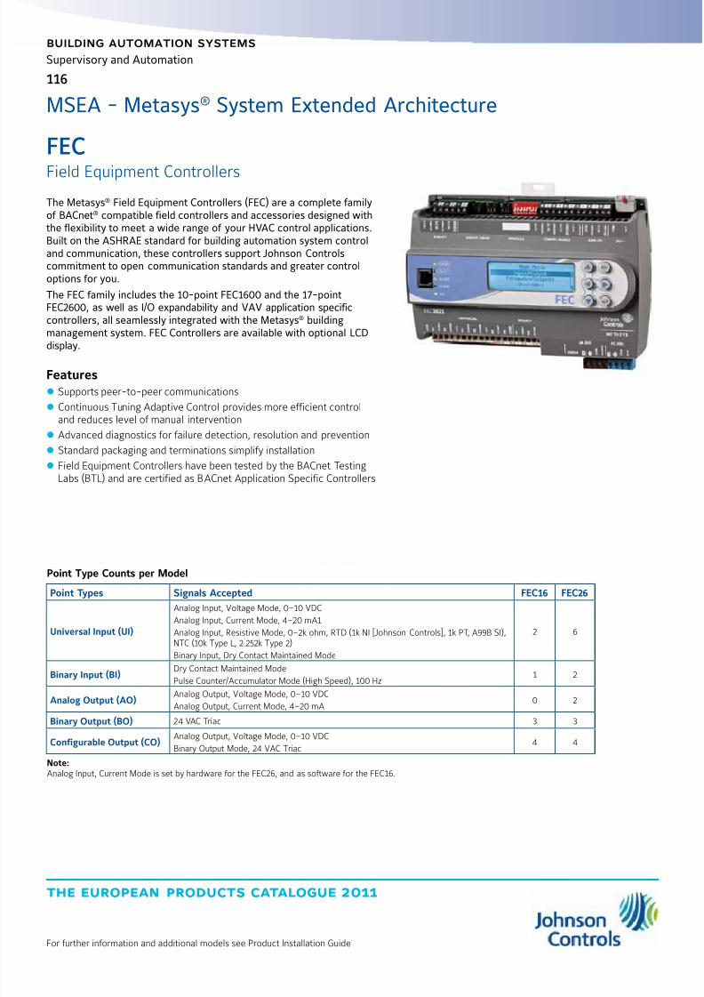
8/6/2019 Publ-6576 Prod Cat 11
http://slidepdf.com/reader/full/publ-6576-prod-cat-11 124/298
the european products catalogue 2011
For further information and additional models see Product Installation Guide
building automation systems
116
Supervisory and Automation
FEC
Field Equipment ControllersThe Metasys® Field Equipment Controllers (FEC) are a complete familyof BACnet® compatible field controllers and accessories designed withthe flexibility to meet a wide range of your HVAC control applications.Built on the ASHRAE standard for building automation system controland communication, these controllers support Johnson Controlscommitment to open communication standards and greater controloptions for you.
The FEC family includes the 10-point FEC1600 and the 17-pointFEC2600, as well as I/O expandability and VAV application specificcontrollers, all seamlessly integrated with the Metasys® buildingmanagement system. FEC Controllers are available with optional LCD
display.
Features z Supports peer-to-peer communications
z Continuous Tuning Adaptive Control provides more efficient controland reduces level of manual intervention
z Advanced diagnostics for failure detection, resolution and prevention
z Standard packaging and terminations simplify installation
z Field Equipment Controllers have been tested by the BACnet TestingLabs (BTL) and are certified as BACnet Application Specific Controllers
MSEA - Metasys® System Extended Architecture
Point Type Counts per Model
Point Types Signals Accepted FEC16 FEC26
Universal Input (UI)
Analog Input, Voltage Mode, 0–10 VDC
Analog Input, Current Mode, 4–20 mA1
Analog Input, Resistive Mode, 0–2k ohm, RTD (1k NI [Johnson Controls], 1k PT, A99B SI),NTC (10k Type L, 2.252k Type 2)
Binary Input, Dry Contact Maintained Mode
2 6
Binary Input (BI)Dry Contact Maintained Mode
Pulse Counter/Accumulator Mode (High Speed), 100 Hz1 2
Analog Output (AO) Analog Output, Voltage Mode, 0–10 VDCAnalog Output, Current Mode, 4–20 mA 0 2
Binary Output (BO) 24 VAC Triac 3 3
Configurable Output (CO)Analog Output, Voltage Mode, 0–10 VDC
Binary Output Mode, 24 VAC Triac4 4
Note:Analog Input, Current Mode is set by hardware for the FEC26, and as software for the FEC16.

8/6/2019 Publ-6576 Prod Cat 11
http://slidepdf.com/reader/full/publ-6576-prod-cat-11 125/298
the european products catalogue 2011
For further information and additional models see Product Installation Guide
117
building automation systems
Supervisory and Automation
FECField Equipment Controllers
Ordering Codes Description
MS-FEC1611-0 10-Point Field Equipment Controller with 2 UI, 1 BI, 3 BO, and 4 CO; 24 VAC; SA Bus
MS-FEC1621-0 10-Point Field Equipment Controller with 2 UI, 1 BI, 3 BO, and 4 CO; 24 VAC; SA Bus; Integral Display
MS-FEC2611-0 17-Point Field Equipment Controller with 6 UI, 2 BI, 3 BO, 2 AO, and 4 CO; 24 VAC; SA Bus
MS-FEC2621-0 Field Equipment Controller Cover with 6 UI, 2 BI, 3 BO, 2 AO, and 4 CO; 24 VAC; SA Bus; Integral Display
Accessories
Ordering Codes Description
Y64T15-0Transformer, 120/208/240 VAC Primary to 24 VAC Secondary, 92 VA, Foot Mount,30 in. Primary Leads and 30 in. Secondary Leads, Class 2
Y65T31-0Transformer, 120/208/240 VAC Primary to 24 VAC Secondary, 40 VA, Foot Mount (Y65AR+),8 in. Primary Leads and Secondary Screw Terminals, Class 2
AP-TBK4SA-0 Replacement MS/TP SA Bus Terminal, 4-Position Connector, Brown, Bulk Pack
AP-TBK4FC-0 Replacement MS/TP FC Bus Terminal, 4-Position Connector, Blue, Bulk Pack
AP-TBK3PW-0 Replacement Power Terminal, 3-Position Connector, Gray, Bulk Pack
MS-DIS1710-0 Local Controller Display for FEC1611 and FEC2611 Models
MS-BTCVT-1 Wireless Commissioning Converter, with Bluetooth® technology
MS-BTCVTCBL-700 Cable replacement Set for the MS-BTCVT-1 or the NS-ATV7003-0; includes one 5-foot retractable cable
MS-ZFR1810-0Wireless Field Bus Coordinator, 10 mW Transmission Power.Functions with NAE35xx, NAE45xx, NAE55xx, and NCE25xx models.
MS-ZFR1811-0Wireless Field Bus Router, 10 mW Transmission Power.Functions with Metasys BACnet FECs, VMA1600s, and WRZ-TTx Series Wireless Mesh Room Temperature Sensors.
MS-ZFRCBL-0Wire Harness for use with ZFR1811 Router. Allows ZFR1811 Router to function with FEC1621;and with FEC1611, VMA1610, or VMA1620 controllers in conjunction with NS Series Sensors.Wireless Commissioning Converter, or DIS1710 Local Controller Display.

8/6/2019 Publ-6576 Prod Cat 11
http://slidepdf.com/reader/full/publ-6576-prod-cat-11 126/298
the european products catalogue 2011
For further information and additional models see Product Installation Guide
118
building automation systems
Supervisory and Automation
Technical Specifications
Supply Voltage 24 VAC (nominal, 20 VAC minimum/30 VAC maximum), 50/60 Hz, Safety Extra-Low Voltage (SELV) (Europe)
Power Consumption 14 VA maximum for FEC1611 and FEC2611 (no integral display)
20 VA maximum for FEC1621 and FEC2621 (with integral display)
Note: VA ratings do not include any power supplied to the peripheral devices connected to Binary Outputs (BOs) orConfigurable Outputs (COs), which can consume up to 12 VA for each BO or CO; for a possible total consumption of anadditional 84 VA (maximum).
Ambient Conditions
Operating: 0 to 50°C; 10 to 90% RH noncondensing
Storage Temperature: -40 to 80°C; 5 to 95% RH noncondensing
Controller Addressing DIP switch set; valid field controller device addresses 4–127
(Device addresses 0–3 and 128–255 are reserved and not valid field controller addresses.)
Communications Bus BACnet® MS/TP, RS-485:3-wire FC Bus between the supervisory controller and field controllers4-wire SA Bus between field controller, network sensors, and other sensor/actuator devices,includes a lead to source 15 VDC supply power (from field controller) to bus devices*.
Processor H8SX/166xR Renesas® microcontroller
Memory 1 MB Flash Memory and 512 KB Random Access Memory (RAM)
Input and Output Capabilities
FEC16 Models: 2 - Universal Inputs: Defined as 0–10 VDC, 4–20 mA, 0–600k ohm, or Binary Dry Contact
1 - Binary Inputs: Defined as Dry Contact Maintained or Pulse Counter/Accumulator Mode
3 - Binary Outputs: Defined as 24 VAC Triac (selectable internal or external source power)
4 - Configurable Outputs: Defined as 0–10 VDC or 24 VAC Triac BO
FEC26 Models:: 6 - Universal Inputs: Defined as 0–10 VDC, 4–20 mA, 0–600k ohm, or Binary Dry Contact
2 - Binary Inputs: Defined as Dry Contact Maintained or Pulse Counter/Accumulator Mode
3 - Binary Outputs: Defined as 24 VAC Triac (selectable internal or external source power)
4 - Configurable Outputs: Defined as 0–10 VDC or 24 VAC Triac BO
2 - Analog Outputs: Defined as 0–10 VDC or 4–20 mA
Analog Input/Analog OutputResolution and Accuracy
Analog Input: 16-bit resolution
Analog Output: 16-bit resolution and ±200 mV in 0–10 VDC applications
Terminations Input/Output: Fixed Screw Terminal Blocks
FC Bus, SA Bus, and Supply Power: 3-Wire and 4-Wire Pluggable Screw Terminal Blocks
FC Bus and SA Bus: RJ-12 6-Pin Modular Jacks
Mounting Horizontal on single 35 mm DIN rail mount (preferred), or screw mount on flat surface with three integralmounting clips on controller
Housing Enclosure material: ABS and polycarbonate UL94 5VB; Self-extinguishing, Plenum-rated Protection Class: IP20 (IEC529)
Dimensions (H x W x D)
FEC16 Models: 150 x 164 x 53 mm including terminals and mounting clips
FEC26 Models: 150 x 190 x 53 mm including terminals and mounting clips
Note: Mounting space for FEC16 and FEC26 Models requires an additional 50 mm space on top, bottom, and front
face of controller for easy cover removal, ventilation, and wire terminations.Weight
FEC16 Models: 0.4 kg
FEC26 Models: 0.5 kg
Compliance
Europe: CE Mark, EMC Directive 2004/108/EC, in accordance with EN 61000-6-3 (2007) Generic Emission Standard for Residential
and Light Industry and EN 61000-6-2 (2005) Generic Immunity Standard for Heavy Industrial Environment
Note: For FEC26 Models, Conducted RF Immunity within EN 61000-6-2 meets performance criteria B.
BACnet International: BACnet Testing Laboratories (BTL) 135-2004 Listed BACnet Application Specific Controller (B-ASC)
FECField Equipment Controllers
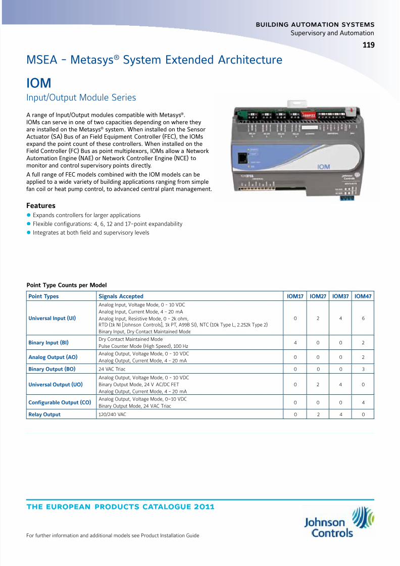
8/6/2019 Publ-6576 Prod Cat 11
http://slidepdf.com/reader/full/publ-6576-prod-cat-11 127/298
the european products catalogue 2011
For further information and additional models see Product Installation Guide
119
building automation systems
119
Supervisory and Automation
IOM
Input/Output Module SeriesA range of Input/Output modules compatible with Metasys®.IOMs can serve in one of two capacities depending on where theyare installed on the Metasys® system. When installed on the SensorActuator (SA) Bus of an Field Equipment Controller (FEC), the IOMsexpand the point count of these controllers. When installed on theField Controller (FC) Bus as point multiplexors, IOMs allow a NetworkAutomation Engine (NAE) or Network Controller Engine (NCE) tomonitor and control supervisory points directly.
A full range of FEC models combined with the IOM models can beapplied to a wide variety of building applications ranging from simplefan coil or heat pump control, to advanced central plant management.
Features z Expands controllers for larger applications
z Flexible configurations: 4, 6, 12 and 17-point expandability
z Integrates at both field and supervisory levels
MSEA - Metasys® System Extended Architecture
Point Type Counts per Model
Point Types Signals Accepted IOM17 IOM27 IOM37 IOM47
Universal Input (UI)
Analog Input, Voltage Mode, 0 - 10 VDC
Analog Input, Current Mode, 4 - 20 mA
Analog Input, Resistive Mode, 0 - 2k ohm,RTD (1k NI [Johnson Controls], 1k PT, A99B SI), NTC (10k Type L, 2.252k Type 2)
Binary Input, Dry Contact Maintained Mode
0 2 4 6
Binary Input (BI)Dry Contact Maintained Mode
Pulse Counter Mode (High Speed), 100 Hz4 0 0 2
Analog Output (AO)Analog Output, Voltage Mode, 0 - 10 VDC
Analog Output, Current Mode, 4 - 20 mA0 0 0 2
Binary Output (BO) 24 VAC Triac 0 0 0 3
Universal Output (UO)Analog Output, Voltage Mode, 0 - 10 VDC
Binary Output Mode, 24 V AC/DC FET
Analog Output, Current Mode, 4 - 20 mA
0 2 4 0
Configurable Output (CO)Analog Output, Voltage Mode, 0–10 VDCBinary Output Mode, 24 VAC Triac
0 0 0 4
Relay Output 120/240 VAC 0 2 4 0
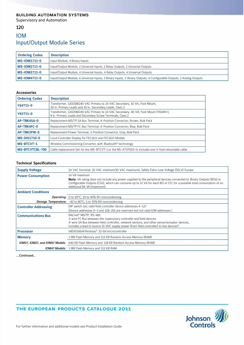
8/6/2019 Publ-6576 Prod Cat 11
http://slidepdf.com/reader/full/publ-6576-prod-cat-11 128/298
the european products catalogue 2011
For further information and additional models see Product Installation Guide
120
building automation systems
Supervisory and Automation
IOMInput/Output Module Series
Ordering Codes Description
MS-IOM1711-0 Input Module, 4 Binary Inputs
MS-IOM2711-0 Input/Output Module, 2 Universal Inputs, 2 Relay Outputs, 2 Universal Outputs
MS-IOM3711-0 Input/Output Module, 4 Universal Inputs, 4 Relay Outputs, 4 Universal Outputs
MS-IOM4711-0 Input/Output Module, 6 Universal Inputs, 2 Binary Inputs, 3 Binary Outputs, 4 Configurable Outputs, 2 Analog Outputs
Accessories
Ordering Codes Description
Y64T15-0Transformer, 120/208/240 VAC Primary to 24 VAC Secondary, 92 VA, Foot Mount,30 in. Primary Leads and 30 in. Secondary Leads, Class 2
Y65T31-0Transformer, 120/208/240 VAC Primary to 24 VAC Secondary, 40 VA, Foot Mount (Y65AR+),8 in. Primary Leads and Secondary Screw Terminals, Class 2
AP-TBK4SA-0 Replacement MS/TP SA Bus Terminal, 4-Position Connector, Brown, Bulk Pack
AP-TBK4FC-0 Replacement MS/TP FC Bus Terminal, 4-Position Connector, Blue, Bulk Pack
AP-TBK3PW-0 Replacement Power Terminal, 3-Position Connector, Gray, Bulk Pack
MS-DIS1710-0 Local Controller Display for FEC1611 and FEC2611 Models
MS-BTCVT-1 Wireless Commissioning Converter, with Bluetooth® technology
MS-BTCVTCBL-700 Cable replacement Set for the MS-BTCVT-1 or the NS-ATV7003-0; includes one 5-foot retractable cable
Technical Specifications
Supply Voltage 24 VAC (nominal, 20 VAC minimum/30 VAC maximum), Safety Extra-Low Voltage (SELV) Europe
Power Consumption 14 VA maximum
Note: VA rating does not include any power supplied to the peripheral devices connected to Binary Outputs (BOs) orConfigurable Outputs (COs), which can consume up to 12 VA for each BO or CO; for a possible total consumption of anadditional 84 VA (maximum).
Ambient Conditions
Operating: 0 to 50°C; 10 to 90% RH noncondensing
Storage Temperature: -40 to 80°C; 5 to 95% RH noncondensing
Controller Addressing DIP switch set; valid field controller device addresses 4–127
(Device addresses 0–3 and 128–255 are reserved and not valid IOM addresses.)
Communications Bus BACnet® MS/TP, RS-485:3-wire FC Bus between the supervisory controller and field devices4-wire SA Bus between field controller, network sensors, and other sensor/actuator devices,includes a lead to source 15 VDC supply power (from field controller) to bus devices*.
Processor H8SX/166xR Renesas® 32-bit microcontroller
Memory 1 MB Flash Memory and 512 KB Random Access Memory (RAM)
IOM17, IOM27, and IOM37 Models: 640 KB Flash Memory and 128 KB Random Access Memory (RAM)
IOM47 Models: 1 MB Flash Memory and 512 KB RAM
...Continued...
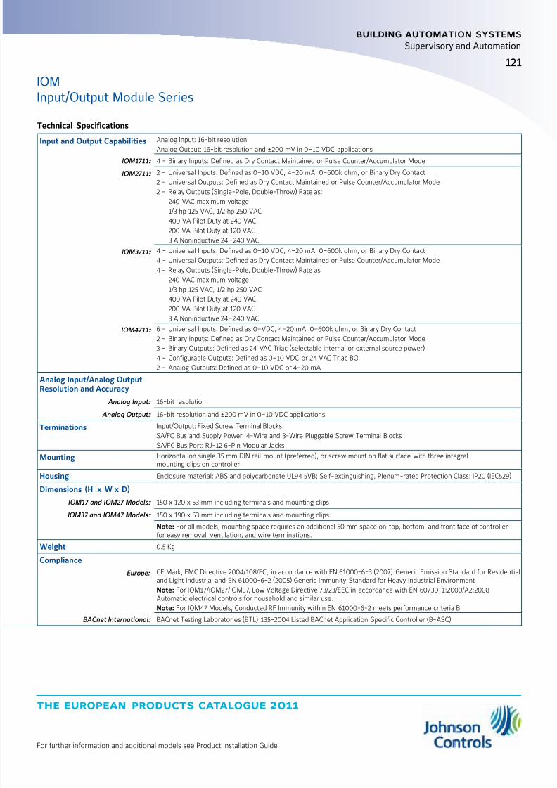
8/6/2019 Publ-6576 Prod Cat 11
http://slidepdf.com/reader/full/publ-6576-prod-cat-11 129/298
the european products catalogue 2011
For further information and additional models see Product Installation Guide
121
building automation systems
Supervisory and Automation
IOMInput/Output Module Series
Technical Specifications
Input and Output Capabilities Analog Input: 16-bit resolutionAnalog Output: 16-bit resolution and ±200 mV in 0–10 VDC applications
IOM1711: 4 - Binary Inputs: Defined as Dry Contact Maintained or Pulse Counter/Accumulator Mode
IOM2711: 2 - Universal Inputs: Defined as 0–10 VDC, 4–20 mA, 0–600k ohm, or Binary Dry Contact
2 - Universal Outputs: Defined as Dry Contact Maintained or Pulse Counter/Accumulator Mode
2 - Relay Outputs (Single-Pole, Double-Throw) Rate as:
240 VAC maximum voltage
1/3 hp 125 VAC, 1/2 hp 250 VAC
400 VA Pilot Duty at 240 VAC
200 VA Pilot Duty at 120 VAC
3 A Noninductive 24–240 VAC
IOM3711: 4 - Universal Inputs: Defined as 0–10 VDC, 4–20 mA, 0–600k ohm, or Binary Dry Contact
4 - Universal Outputs: Defined as Dry Contact Maintained or Pulse Counter/Accumulator Mode
4 - Relay Outputs (Single-Pole, Double-Throw) Rate as:
240 VAC maximum voltage
1/3 hp 125 VAC, 1/2 hp 250 VAC
400 VA Pilot Duty at 240 VAC
200 VA Pilot Duty at 120 VAC
3 A Noninductive 24–240 VAC
IOM4711: 6 - Universal Inputs: Defined as 0–VDC, 4–20 mA, 0–600k ohm, or Binary Dry Contact
2 - Binary Inputs: Defined as Dry Contact Maintained or Pulse Counter/Accumulator Mode
3 - Binary Outputs: Defined as 24 VAC Triac (selectable internal or external source power)
4 - Configurable Outputs: Defined as 0–10 VDC or 24 VAC Triac BO
2 - Analog Outputs: Defined as 0–10 VDC or 4–20 mA
Analog Input/Analog OutputResolution and Accuracy
Analog Input: 16-bit resolution
Analog Output: 16-bit resolution and ±200 mV in 0–10 VDC applications
Terminations Input/Output: Fixed Screw Terminal Blocks
SA/FC Bus and Supply Power: 4-Wire and 3-Wire Pluggable Screw Terminal Blocks
SA/FC Bus Port: RJ-12 6-Pin Modular Jacks
Mounting Horizontal on single 35 mm DIN rail mount (preferred), or screw mount on flat surface with three integralmounting clips on controller
Housing Enclosure material: ABS and polycarbonate UL94 5VB; Self-extinguishing, Plenum-rated Protection Class: IP20 (IEC529)
Dimensions (H x W x D)
IOM17 and IOM27 Models: 150 x 120 x 53 mm including terminals and mounting clips
IOM37 and IOM47 Models: 150 x 190 x 53 mm including terminals and mounting clips
Note: For all models, mounting space requires an additional 50 mm space on top, bottom, and front face of controllerfor easy removal, ventilation, and wire terminations.
Weight 0.5 Kg
Compliance
Europe: CE Mark, EMC Directive 2004/108/EC, in accordance with EN 61000-6-3 (2007) Generic Emission Standard for Residentialand Light Industrial and EN 61000-6-2 (2005) Generic Immunity Standard for Heavy Industrial Environment
Note: For IOM17/IOM27/IOM37, Low Voltage Directive 73/23/EEC in accordance with EN 60730-1:2000/A2:2008Automatic electrical controls for household and similar use.
Note: For IOM47 Models, Conducted RF Immunity within EN 61000-6-2 meets performance criteria B.
BACnet International: BACnet Testing Laboratories (BTL) 135-2004 Listed BACnet Application Specific Controller (B-ASC)
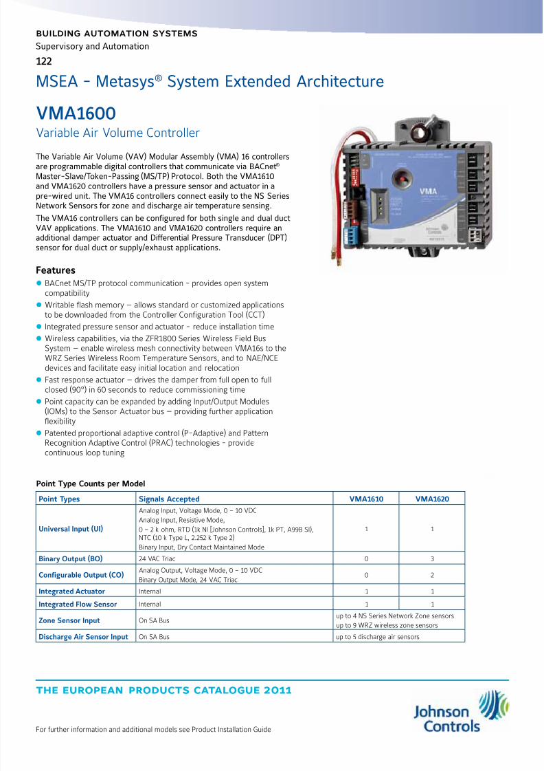
8/6/2019 Publ-6576 Prod Cat 11
http://slidepdf.com/reader/full/publ-6576-prod-cat-11 130/298
the european products catalogue 2011
For further information and additional models see Product Installation Guide
building automation systems
122
Supervisory and Automation
The Variable Air Volume (VAV) Modular Assembly (VMA) 16 controllersare programmable digital controllers that communicate via BACnet® Master-Slave/Token-Passing (MS/TP) Protocol. Both the VMA1610and VMA1620 controllers have a pressure sensor and actuator in apre-wired unit. The VMA16 controllers connect easily to the NS SeriesNetwork Sensors for zone and discharge air temperature sensing.
The VMA16 controllers can be configured for both single and dual ductVAV applications. The VMA1610 and VMA1620 controllers require anadditional damper actuator and Differential Pressure Transducer (DPT)sensor for dual duct or supply/exhaust applications.
Features z BACnet MS/TP protocol communication - provides open systemcompatibility
z Writable flash memory — allows standard or customized applicationsto be downloaded from the Controller Configuration Tool (CCT)
z Integrated pressure sensor and actuator - reduce installation time
z Wireless capabilities, via the ZFR1800 Series Wireless Field BusSystem — enable wireless mesh connectivity between VMA16s to theWRZ Series Wireless Room Temperature Sensors, and to NAE/NCEdevices and facilitate easy initial location and relocation
z Fast response actuator — drives the damper from full open to fullclosed (90°) in 60 seconds to reduce commissioning time
z
Point capacity can be expanded by adding Input/Output Modules(IOMs) to the Sensor Actuator bus — providing further applicationflexibility
z Patented proportional adaptive control (P-Adaptive) and PatternRecognition Adaptive Control (PRAC) technologies - providecontinuous loop tuning
VMA1600
Variable Air Volume Controller
MSEA - Metasys® System Extended Architecture
Point Type Counts per Model
Point Types Signals Accepted VMA1610 VMA1620
Universal Input (UI)
Analog Input, Voltage Mode, 0 – 10 VDC
Analog Input, Resistive Mode,
0 – 2 k ohm, RTD (1k NI [Johnson Controls], 1k PT, A99B SI),
NTC (10 k Type L, 2.252 k Type 2)Binary Input, Dry Contact Maintained Mode
1 1
Binary Output (BO) 24 VAC Triac 0 3
Configurable Output (CO)Analog Output, Voltage Mode, 0 – 10 VDC
Binary Output Mode, 24 VAC Triac0 2
Integrated Actuator Internal 1 1
Integrated Flow Sensor Internal 1 1
Zone Sensor Input On SA Busup to 4 NS Series Network Zone sensors
up to 9 WRZ wireless zone sensors
Discharge Air Sensor Input On SA Bus up to 5 discharge air sensors

8/6/2019 Publ-6576 Prod Cat 11
http://slidepdf.com/reader/full/publ-6576-prod-cat-11 131/298
the european products catalogue 2011
For further information and additional models see Product Installation Guide
123
building automation systems
Supervisory and Automation
VMA1600Variable Air Volume Controller
Ordering Codes Description
MS-VMA1610-0 Integrated VAV Controller/Actuator/Pressure Sensor (Cooling Only), FC Bus, and SA Bus
MS-VMA1620-0 Integrated VAV Controller/Actuator/Pressure Sensor (with Reheat and Fan Control), FC Bus, and SA Bus
Accessories
Ordering Codes Description
Y64T15-0Transformer, 120/208/240 VAC Primary to 24 VAC Secondary, 92 VA, Foot Mount, 750 mm Primary Leadsand 750 mm Secondary Leads, Class 2
Y65A13-0Transformer, 120 VAC Primary to 24 VAC Secondary, 40 VA, Foot Mount (Y65AS), 200 mm Primary Leadsand 750 mm Secondary Leads, Class 2
Y65T42-0Transformer, 120/208/240 VAC Primary to 24 VAC Secondary, 40 VA, Hub Mount (Y65SP+), 200 mm Primary Leadsand Secondary Screw Terminals, Class 2
Y65T31-0Transformer, 120/208/240 VAC Primary to 24 VAC Secondary, 40 VA, Foot Mount (Y65AR+), 200 mm Primary Leadsand Secondary Screw Terminals, Class 2
AP-TBK1002-0 2-Position Screw Terminal that Plugs onto VMA output point Spade Lugs
AP-TBK1003-0 3-Position Screw Terminal that Plugs onto VMA output point Spade Lugs
AP-TBK4SA-0 Replacement MS/TP SA Bus Terminal, 4-Position Connector, Brown, Bulk Pack
AP-TBK4FC-0 Replacement MS/TP FC Bus Terminal, 4-Position Connector, Blue, Bulk Pack
AP-TBK3PW-0 Replacement Power Terminal, 3-Position Connector, Gray, Bulk Pack
MS-BTCVT-1 Wireless Commissioning Converter, with Bluetooth® technology
MS-BTCVTCBL- 700 Cable replacement Set for the MS-BTCVT-1 or the NS-ATV7003-0; includes one 1.5 m retractable cable.
MS-ZFR1810-0 Wireless Field Bus Coordinator, 10 mW Transmission Power. Functions with NAE35xx, NAE45xx, NAE55xx, and NCE25xx Models.
MS-ZFR1811-0Wireless Field Bus Router, 10 mW Transmission Power. Functions with Metasys BACnet FECs, VMA1600s, and WRZ-TTx SeriesWireless Mesh Room Temperature Sensors.
MS-ZFRCBL-0
Wire Harness for use with ZFR1811 Router. Allows ZFR1811 Router to function with FEC1621; and with FEC1611, VMA1610,
or VMA1620 controllers in conjunction with NS Series Sensors. Wireless Commissioning Converter, or DIS1710 Local Controller Display.

8/6/2019 Publ-6576 Prod Cat 11
http://slidepdf.com/reader/full/publ-6576-prod-cat-11 132/298
the european products catalogue 2011
For further information and additional models see Product Installation Guide
124
building automation systems
Supervisory and Automation
VMA1600Variable Air Volume Controller
Technical Specifications
Power Requirement
Voltage: 24 VAC (nominal, 20 VAC minimum / 30 VAC maximum), 50/60 Hz, Safety Extra-Low Voltage (SELV) (Europe)
Consumption: 10 VA typical, 14 VA maximum
Note: VA rating does not include any power supplied to the peripheral devices connected to Binary Outputs (BOs) orConfigurable Outputs (COs), which can consume up to 12 VA for each BO or CO for a possible total consumption of anadditional 60 VA (maximum).
Ambient Conditions
Operating: 0 to 50°C
Storage Temperature: -40 to 70°C
Terminations 6.3 mm spade lugs
FC Bus, SA Bus
Supply Power: 4-Wire and 3-Wire Pluggable Screw Terminal Blocks
Sensor Port: RJ-12 6-Pin Modular Jacks
Controller Addressing DIP switch set; valid field controller device addresses 4–127(Device addresses 0–3 and 125–255 are reserved and not valid field controller addresses)
Communications Bus BACnet MS/TP, RS-485:3-wire FC Bus between the supervisory controller and field controllers4-wire SA Bus from the VMA controller, network sensors, and other sensor/actuator devices
includes a terminal to source 15 VDC supply power from VMA to SA Bus devices. *
Analog Input / Analog OutputsResolution
Analog Input: 15-bit resolution
Analog Output: 16-bit resolution and ±200 mV in 0-10 VDC applications
Air PressureDifferential Sensor
Setra transducer, differential pressure to electrical, 0 to 38.1 mm WC, 0.5 to 4.5 VDC, 5 VDC supply, aluminum plated.
Performance Characteristics: Combined Repeatability and Hysteresis Error: ±0.05% of Full Span Maximum
Non-linearity Errors (Best Fit Method): ±1.0% of Full Span Maximum
Response Time (to within 63% of Full Scale Pressure with Step Change on Input): 15 ms
Temperature Error from 15.6 to 48.9°C
Null: ±0.06% of Full Span per °F Maximum
Span: ±1.5% of Full Span Maximum
Stability, Null: ±0.5% of Full Scale Maximum, 1 Year Minimum
Stability, Span: ±2.0% of Full Scale Maximum, 1 Year Minimum
Actuator Rating 4 N•m minimum shaft length = 44 mm
Dimensions (H x W x D) 182 x 182 x 64 mmCenter of Output Hub to Center of Anti-rotation Slot: 160 mm
Weight 0.86 kg
Compliance CE Mark, EMC Directive 89/336/EEC, in accordance with EN 61000-6-3 (2001) Generic Emission Standard for Residentialand Light Industry and EN 61000-6-2 (2001) Generic Immunity Standard for Heavy Industrial Equipment,
and the Low Voltage Directive 73/23/EEC in accordance with EN 60730-1 (1999) Automatic electrical controls forhousehold and similar use.
BACnet International: BACnet Testing Laboratories (BTL) 135-2004 Listed BACnet Application Specific Controller (B-ASC)
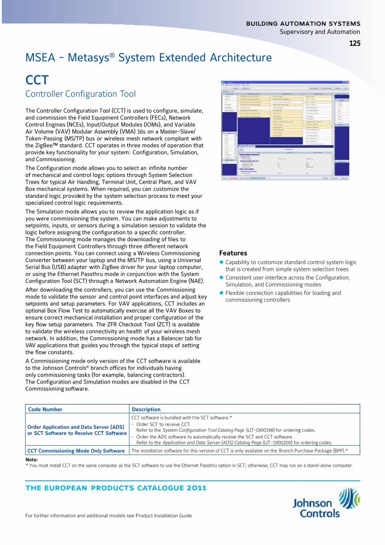
8/6/2019 Publ-6576 Prod Cat 11
http://slidepdf.com/reader/full/publ-6576-prod-cat-11 133/298
the european products catalogue 2011
For further information and additional models see Product Installation Guide
125
building automation systems
125
Supervisory and Automation
CCT
Controller Configuration ToolThe Controller Configuration Tool (CCT) is used to configure, simulate,and commission the Field Equipment Controllers (FECs), NetworkControl Engines (NCEs), Input/Output Modules (IOMs), and VariableAir Volume (VAV) Modular Assembly (VMA) 16s on a Master-Slave/Token-Passing (MS/TP) bus or wireless mesh network compliant withthe ZigBee™ standard. CCT operates in three modes of operation thatprovide key functionality for your system: Configuration, Simulation,and Commissioning.
The Configuration mode allows you to select an infinite numberof mechanical and control logic options through System SelectionTrees for typical Air Handling, Terminal Unit, Central Plant, and VAV
Box mechanical systems. When required, you can customize thestandard logic provided by the system selection process to meet yourspecialized control logic requirements.
The Simulation mode allows you to review the application logic as if you were commissioning the system. You can make adjustments tosetpoints, inputs, or sensors during a simulation session to validate thelogic before assigning the configuration to a specific controller.The Commissioning mode manages the downloading of files tothe Field Equipment Controllers through three different networkconnection points. You can connect using a Wireless CommissioningConverter between your laptop and the MS/TP bus, using a UniversalSerial Bus (USB) adapter with ZigBee driver for your laptop computer,or using the Ethernet Passthru mode in conjunction with the SystemConfiguration Tool (SCT) through a Network Automation Engine (NAE).
After downloading the controllers, you can use the Commissioningmode to validate the sensor and control point interfaces and adjust keysetpoints and setup parameters. For VAV applications, CCT includes anoptional Box Flow Test to automatically exercise all the VAV Boxes toensure correct mechanical installation and proper configuration of thekey flow setup parameters. The ZFR Checkout Tool (ZCT) is availableto validate the wireless connectivity an health of your wireless meshnetwork. In addition, the Commissioning mode has a Balancer tab forVAV applications that guides you through the typical steps of settingthe flow constants.
A Commissioning mode only version of the CCT software is availableto the Johnson Controls® branch offices for individuals havingonly commissioning tasks (for example, balancing contractors).
The Configuration and Simulation modes are disabled in the CCTCommissioning software.
MSEA - Metasys® System Extended Architecture
Code Number Description
Order Application and Data Server (ADS)or SCT Software to Receive CCT Software
CCT software is bundled with the SCT software.*
- Order SCT to receive CCT.Refer to the System Configuration Tool Catalog Page (LIT-1900198) for ordering codes.
- Order the ADS software to automatically receive the SCT and CCT software.Refer to the Application and Data Server (ADS) Catalog Page (LIT-1900200) for ordering codes.
CCT Commissioning Mode Only Software The installation software for this version of CCT is only available on the Branch Purchase Package (BPP).*
Note:* You must install CCT on the same computer as the SCT software to use the Ethernet Passthru option in SCT; otherwise, CCT may run on a stand-alone computer.
Features z Capability to customize standard control system logicthat is created from simple system selection trees
z Consistent user interface across the Configuration,
Simulation, and Commissioning modes z Flexible connection capabilities for loading andcommissioning controllers
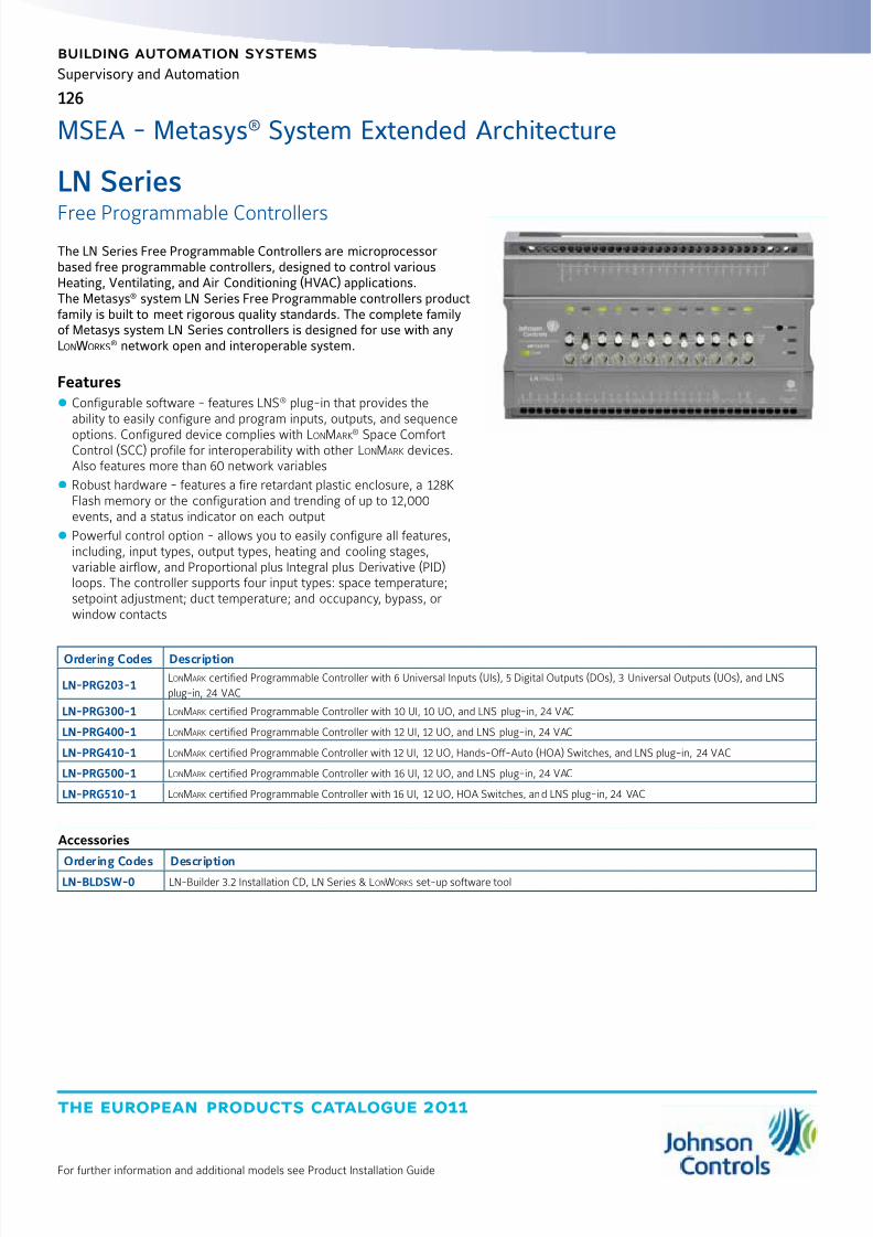
8/6/2019 Publ-6576 Prod Cat 11
http://slidepdf.com/reader/full/publ-6576-prod-cat-11 134/298
the european products catalogue 2011
For further information and additional models see Product Installation Guide
building automation systems
126
Supervisory and Automation
LN Series
Free Programmable ControllersThe LN Series Free Programmable Controllers are microprocessorbased free programmable controllers, designed to control variousHeating, Ventilating, and Air Conditioning (HVAC) applications.The Metasys® system LN Series Free Programmable controllers productfamily is built to meet rigorous quality standards. The complete familyof Metasys system LN Series controllers is designed for use with anyLonWorks
® network open and interoperable system.
Features z Configurable software - features LNS® plug-in that provides theability to easily configure and program inputs, outputs, and sequence
options. Configured device complies with LonMark® Space ComfortControl (SCC) profile for interoperability with other LonMark devices.Also features more than 60 network variables
z Robust hardware - features a fire retardant plastic enclosure, a 128KFlash memory or the configuration and trending of up to 12,000events, and a status indicator on each output
z Powerful control option - allows you to easily configure all features,including, input types, output types, heating and cooling stages,variable airflow, and Proportional plus Integral plus Derivative (PID)loops. The controller supports four input types: space temperature;setpoint adjustment; duct temperature; and occupancy, bypass, orwindow contacts
Ordering Codes Description
LN-PRG203-1LonMark certified Programmable Controller with 6 Universal Inputs (UIs), 5 Digital Outputs (DOs), 3 Universal Outputs (UOs), and LNS
plug-in, 24 VAC
LN-PRG300-1 LonMark certified Programmable Controller with 10 UI, 10 UO, and LNS plug-in, 24 VAC
LN-PRG400-1 LonMark certified Programmable Controller with 12 UI, 12 UO, and LNS plug-in, 24 VAC
LN-PRG410-1 LonMark certified Programmable Controller with 12 UI, 12 UO, Hands-Off-Auto (HOA) Switches, and LNS plug-in, 24 VAC
LN-PRG500-1 LonMark certified Programmable Controller with 16 UI, 12 UO, and LNS plug-in, 24 VAC
LN-PRG510-1 LonMark certified Programmable Controller with 16 UI, 12 UO, HOA Switches, and LNS plug-in, 24 VAC
MSEA - Metasys® System Extended Architecture
Accessories
Ordering Codes DescriptionLN-BLDSW-0 LN-Builder 3.2 Installation CD, LN Series & LonWorks set-up software tool
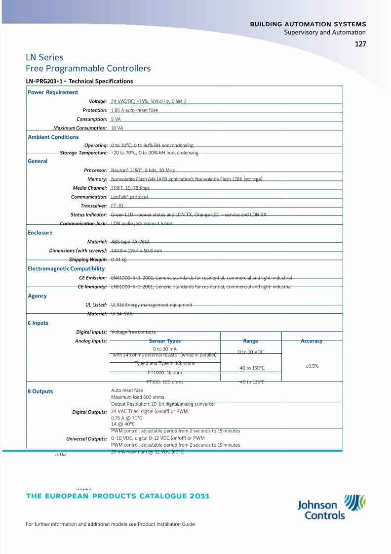
8/6/2019 Publ-6576 Prod Cat 11
http://slidepdf.com/reader/full/publ-6576-prod-cat-11 135/298
the european products catalogue 2011
For further information and additional models see Product Installation Guide
127
building automation systems
Supervisory and Automation
LN SeriesFree Programmable ControllersLN-PRG203-1 - Technical Specifications
Power Requirement
Voltage: 24 VAC/DC; ±15%, 50/60 Hz, Class 2
Protection: 1.85 A auto-reset fuse
Consumption: 5 VA
Maximum Consumption: 18 VA
Ambient Conditions
Operating: 0 to 70°C; 0 to 90% RH noncondensing
Storage Temperature: -20 to 70°C; 0 to 90% RH noncondensing
General
Processor: Neuron® 3150®, 8 bits, 10 MHz
Memory: Nonvolatile Flash 64k (APB application); Nonvolatile Flash 128K (storage)
Media Channel: TP/FT-10; 78 Kbps
Communication: LonTalk® protocol
Transceiver: FT-X1
Status Indicator: Green LED - power status and LON TX, Orange LED - service and LON RX
Communication Jack: LON audio jack mono 3.5 mm
Enclosure
Material: ABS type PA-765A
Dimensions (with screws): 144.8 x 119.4 x 50.8 mm
Shipping Weight: 0.44 kg
Electromagnetic Compatibility
CE Emission: EN61000-6-3: 2001; Generic standards for residential, commercial and light-industrial
CE Immunity: EN61000-6-1: 2001; Generic standards for residential, commercial and light-industrial
Agency
UL Listed: UL916 Energy management equipment
Material: UL94-5VA
6 Inputs
Digital Inputs: Voltage free contacts
Analog Inputs: Sensor Types Range Accuracy
0 to 20 mAwith 249 ohms external resistor (wired in parallel)
0 to 10 VDC
±0.5%Type 2 and Type 3: 10k ohms
-40 to 150°CPT1000: 1k ohm
PT100: 100 ohms -40 to 135°C
8 Outputs Auto reset fuseMaximum load 600 ohms
Output Resolution: 10-bit digital/analog converter
Digital Outputs: 24 VAC Triac, digital (on/off) or PWM
0.75 A @ 70°C1A @ 40°C
PWM control: adjustable period from 2 seconds to 15 minutes
Universal Outputs: 0-10 VDC, digital 0-12 VDC (on/off) or PWM
PWM control: adjustable period from 2 seconds to 15 minutes
20 mA maximum @ 12 VDC (60°C)
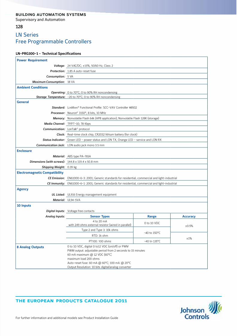
8/6/2019 Publ-6576 Prod Cat 11
http://slidepdf.com/reader/full/publ-6576-prod-cat-11 136/298
the european products catalogue 2011
For further information and additional models see Product Installation Guide
128
building automation systems
Supervisory and Automation
LN SeriesFree Programmable Controllers
LN-PRG300-1 - Technical Specifications
Power Requirement
Voltage: 24 VAC/DC; ±15%, 50/60 Hz, Class 2
Protection: 1.85 A auto-reset fuse
Consumption: 5 VA
Maximum Consumption: 18 VA
Ambient Conditions
Operating: 0 to 70°C; 0 to 90% RH noncondensing
Storage Temperature: -20 to 70°C; 0 to 90% RH noncondensing
General
Standard: LonMark® Functional Profile: SCC-VAV Controller #8502
Processor: Neuron® 3150®, 8 bits, 10 MHz
Memory: Nonvolatile Flash 64k (APB application); Nonvolatile Flash 128K (storage)
Media Channel: TP/FT-10; 78 Kbps
Communication: LonTalk® protocol
Clock: Real-time clock chip, CR2032 lithium battery (for clock)
Status Indicator: Green LED - power status and LON TX, Orange LED - service and LON RX
Communication Jack: LON audio jack mono 3.5 mm
Enclosure
Material: ABS type PA-765A
Dimensions (with screws): 144.8 x 119.4 x 50.8 mm
Shipping Weight: 0.39 kg
Electromagnetic Compatibility
CE Emission: EN61000-6-3: 2001; Generic standards for residential, commercial and light-industrial
CE Immunity: EN61000-6-1: 2001; Generic standards for residential, commercial and light-industrial
Agency
UL Listed: UL916 Energy management equipment
Material: UL94-5VA
10 Inputs
Digital Inputs: Voltage free contacts
Analog Inputs: Sensor Types Range Accuracy
4 to 20 mAwith 249 ohms external resistor (wired in parallel)
0 to 10 VDC±0.5%
Type 2 and Type 3: 10k ohms-40 to 150°C
RTD: 1k ohm ±1%PT100: 100 ohms -40 to 135°C
8 Analog Outputs 0 to 10 VDC, digital 0 to12 VDC (on/off) or PWM
PWM output: adjustable period from 2 seconds to 15 minutes
60 mA maximum @ 12 VDC (60°C)
maximum load 200 ohms
Auto-reset fuse: 60 mA @ 60°C; 100 mA @ 20°C
Output Resolution: 10 bits digital/analog converter

8/6/2019 Publ-6576 Prod Cat 11
http://slidepdf.com/reader/full/publ-6576-prod-cat-11 137/298
the european products catalogue 2011
For further information and additional models see Product Installation Guide
129
building automation systems
Supervisory and Automation
LN SeriesFree Programmable Controllers
LN-PRG410-1 and LN-PRG400-1 - Technical Specifications
Power Requirement
Voltage: 24 VAC/DC; ±15%, 50/60 Hz, Class 2
Protection: 2.5 A auto-reset fuse
Consumption: 5 VA
Maximum Consumption: 18 VA
Power Supply: 15 VDC output used to power 4 to 20 mA inputs
Ambient Conditions
Operating: 0 to 70°C; 0 to 90% RH noncondensing
Storage Temperature: -20 to 70°C; 0 to 90% RH noncondensing
General
Standard: LonMark® Functional Profile: SCC-VAV Controller #8502
Processor: Neuron® 3150®, 8 bits, 10 MHz
Memory: Nonvolatile Flash 64k (APB application); Nonvolatile Flash 128K (storage)
Media Channel: TP/FT-10; 78 Kbps
Communication: LonTalk® protocol
Clock: Real-time clock chip, CR2032 lithium battery (for clock)
Status Indicator: Green LED - power status and LON TX, Orange LED - service and LON RX
Communication Jack: LON audio jack mono 3.5 mm
Enclosure
Material: ABS type PA-765A
Dimensions (with screws): 195.6 x 119.4 x 50.8 mm
Shipping Weight: 0.39 kg
Electromagnetic Compatibility
CE Emission: EN61000-6-3: 2001; Generic standards for residential, commercial and light-industrial
CE Immunity: EN61000-6-1: 2001; Generic standards for residential, commercial and light-industrial
Agency
UL Listed: UL916 Energy management equipment
Material: UL94-5VA
12 Inputs
Digital Inputs: Voltage free contacts
Analog Inputs: Sensor Types Range Accuracy
4 to 20 mAwith 249 ohms external resistor (wired in parallel)
0 to 10 VDC±0.5%
Type 2 and Type 3: 10k ohms -40 to 150°CRTD: 1k ohm
±1%PT100: 100 ohms -40 to 135°C
12 Analog Outputs 0 to 10 VDC, digital 0 to12 VDC (on/off) or PWM
PWM output: adjustable period from 2 seconds to 15 minutes
60 mA maximum @ 12 VDC (60°C)
maximum load 200 ohms
Auto-reset fuse: 60 mA @ 60°C; 100 mA @ 20°C
Output Resolution: 10 bits digital/analog converter
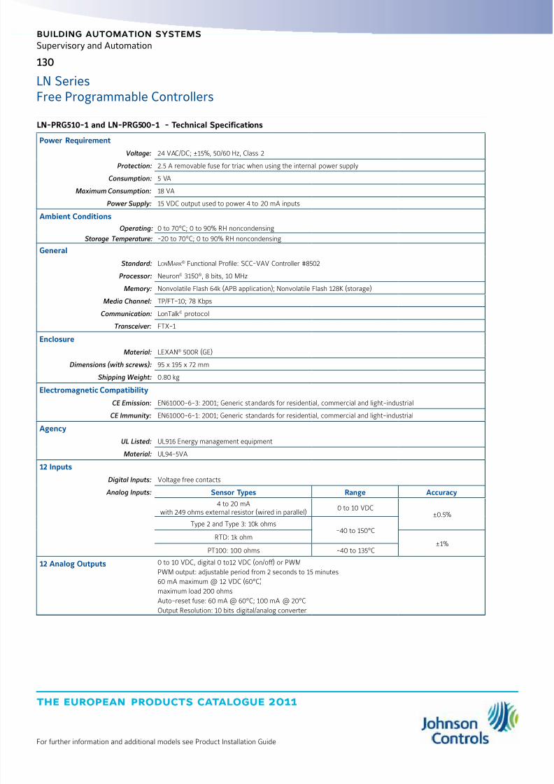
8/6/2019 Publ-6576 Prod Cat 11
http://slidepdf.com/reader/full/publ-6576-prod-cat-11 138/298
the european products catalogue 2011
For further information and additional models see Product Installation Guide
130
building automation systems
Supervisory and Automation
LN SeriesFree Programmable Controllers
LN-PRG510-1 and LN-PRG500-1 - Technical Specifications
Power Requirement
Voltage: 24 VAC/DC; ±15%, 50/60 Hz, Class 2
Protection: 2.5 A removable fuse for triac when using the internal power supply
Consumption: 5 VA
Maximum Consumption: 18 VA
Power Supply: 15 VDC output used to power 4 to 20 mA inputs
Ambient Conditions
Operating: 0 to 70°C; 0 to 90% RH noncondensing
Storage Temperature: -20 to 70°C; 0 to 90% RH noncondensing
General
Standard: LonMark® Functional Profile: SCC-VAV Controller #8502
Processor: Neuron® 3150®, 8 bits, 10 MHz
Memory: Nonvolatile Flash 64k (APB application); Nonvolatile Flash 128K (storage)
Media Channel: TP/FT-10; 78 Kbps
Communication: LonTalk® protocol
Transceiver: FTX-1
Enclosure
Material: LEXAN® 500R (GE)
Dimensions (with screws): 95 x 195 x 72 mm
Shipping Weight: 0.80 kg
Electromagnetic Compatibility
CE Emission: EN61000-6-3: 2001; Generic standards for residential, commercial and light-industrial
CE Immunity: EN61000-6-1: 2001; Generic standards for residential, commercial and light-industrial
Agency
UL Listed: UL916 Energy management equipment
Material: UL94-5VA
12 Inputs
Digital Inputs: Voltage free contacts
Analog Inputs: Sensor Types Range Accuracy
4 to 20 mAwith 249 ohms external resistor (wired in parallel)
0 to 10 VDC±0.5%
Type 2 and Type 3: 10k ohms-40 to 150°C
RTD: 1k ohm±1%
PT100: 100 ohms -40 to 135°C
12 Analog Outputs 0 to 10 VDC, digital 0 to12 VDC (on/off) or PWM
PWM output: adjustable period from 2 seconds to 15 minutes
60 mA maximum @ 12 VDC (60°C)
maximum load 200 ohms
Auto-reset fuse: 60 mA @ 60°C; 100 mA @ 20°C
Output Resolution: 10 bits digital/analog converter
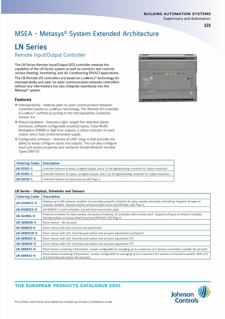
8/6/2019 Publ-6576 Prod Cat 11
http://slidepdf.com/reader/full/publ-6576-prod-cat-11 139/298
the european products catalogue 2011
For further information and additional models see Product Installation Guide
131
building automation systems
131
Supervisory and Automation
LN Series
Remote Input/Output ControllerThe LN Series Remote Input/Output (I/O) controller extends thecapability of the LN Series system as well as monitors and controlsvarious Heating, Ventilating, and Air Conditioning (HVAC) applications.
The LN Remote I/O controllers are based on LonWorks® technology for
interoperability and peer-to-peer communication between controllerswithout any intermediary but also integrate seamlessly into theMetasys® system.
Features z Interoperability - features peer-to-peer communication betweencontrollers based on LonWorks technology. The Remote I/O controlleris LonMark® certified according to the Interoperability GuidelinesVersion 3.4
z Robust hardware - features a light-weight fire retardant plasticenclosure, software configurable universal inputs, Pulse WidthModulation (PWM) or digit triac outputs, a status indicator on eachoutput, and a fuse-protected power supply
z Configurable software - features an LNS® plug-in that provides theability to easily configure inputs and outputs. You can also configureinput and output properties and hardware Simple Network VariableTypes (SNVTs)
Ordering Codes Description
LN-IO301-1 Controller features 8 inputs, 8 digital outputs, and a 12-bit digital/analog converter for output resolution.
LN-IO401-1 Controller features 12 inputs, 12 digital outputs, and a 12-bit digital/analog converter for output resolution.
LN-IO520-1 Controller features 16 inputs and an LNS Plug-in
MSEA - Metasys® System Extended Architecture
LN Series – Displays, Scheduler and Sensors
Ordering Codes Description
LN-DSWSC1-0Displays up to 258 network variables. Incorporates powerful scheduler for daily, weekly, and yearly scheduling. Supports all types of network variables. Standard plastic enclosure (wall mount and DIN Rail), LNS Plug-In
LN-DSWSC2-0 LN-DSWSC1-0 with scheduler, but with flush mount back plate
LN-SCHEDL-0Powerful scheduler for daily, weekly, and yearly scheduling. 16 schedules with 6 events each. Supports all types of network variables.Standard plastic enclosure (wall mount and DIN Rail), LNS Plug-In
LN-SENSOR-0 Room Sensor - No set pointLN-SENSLO-0 Room Sensor with LED and Override push button
LN-SENOCW-0 Room Sensor with LED, Override push button and set point adjustment (cool/warm)
LN-SENOSC-0 Room Sensor with LED, Override push button and set point adjustment (°C)
LN-SENOSF-0 Room Sensor with LED, Override push button and set point adjustment (°F)
LN-SENAV1-0 Room Sensor containing 4 thermistors. Jumper configurable for averaging up to a maximum of 4 sensors connected in parallel. No set point
LN-SENAV2-0Room Sensor containing 4 thermistors. Jumper configurable for averaging up to a maximum of 4 sensors connected in parallel. With LEDand Override push button. No set point
8/6/2019 Publ-6576 Prod Cat 11
http://slidepdf.com/reader/full/publ-6576-prod-cat-11 140/298
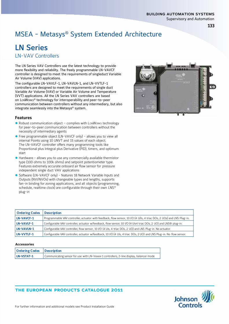
8/6/2019 Publ-6576 Prod Cat 11
http://slidepdf.com/reader/full/publ-6576-prod-cat-11 141/298
the european products catalogue 2011
For further information and additional models see Product Installation Guide
133
building automation systems
133
Supervisory and Automation
LN Series
LN-VAV ControllersThe LN Series VAV Controllers use the latest technology to providemore flexibility and reliability. The freely programmable LN-VAVCFcontroller is designed to meet the requirements of singleduct VariableAir Volume (VAV) applications.
The configurable LN-VAVLF-1, LN-VAVLN-1, and LN-VVTLF-1controllers are designed to meet the requirements of single ductVariable Air Volume (VAV) or Variable Air Volume and Temperature(VVT) applications. All the LN Series VAV controllers are basedon LonWorks
® technology for interoperability and peer-to-peercommunication between controllers without any intermediary, but alsointegrate seamlessly into the Metasys® system.
Features z Robust communication object – complies with LonWorks technologyfor peer-to-peer communication between controllers without thenecessity of intermediary agents
z Free programmable object (LN-VAVCF only) - allows you to view allinternal Points using 10 UNVT and 15 values of each object.The LN-VAVCF controller offers many programming tools likeProportional plus Integral plus Derivative (PID), timers, and optimumstart
z Hardware - allows you to use any commercially available thermistortype (100 ohms to 100k ohms) and setpoint potentiometer type.Features extremely accurate onboard air flow sensor for pressure
independent single duct VAV applications z Software (LN-VAVCF only) - features 18 Network Variable Inputs andOutputs (NVI/NVOs) with changeable types and lengths, supportsfan-in binding for zoning applications, and all objects (programming,schedule, realtime clock) are configurable through their own LNS® plug-in
Ordering Codes Description
LN-VAVCF-1 Programmable VAV controller, actuator with feedback, flow sensor, 10 I/O (4 U/Is, 4 triac DOs, 2 UOs) and LNS Plug-in.
LN-VAVLF-1 Configurable VAV controller, actuator w/feedback, flow sensor, 10 I/O (4 UIs4 triac DOs, 2 UO) and LNS® plug-in.
LN-VAVLN-1 Configurable VAV controller, flow sensor, 10 I/O (4 UIs, 4 triac DOs, 2 UO) and LNS Plug-in. No actuator.
LN-VVTLF-1 Configurable VAV controller, actuator w/feedback, 10 I/O (4 UIs, 4 triac DOs, 2 UO) and LNS Plug-in. No flow sensor.
MSEA - Metasys® System Extended Architecture
Accessories
Ordering Codes Description
LN-VSTAT-1 Communicating sensor for use with LN-Vxxxx-1 controllers, 2-line display, balancer mode
8/6/2019 Publ-6576 Prod Cat 11
http://slidepdf.com/reader/full/publ-6576-prod-cat-11 142/298
the european products catalogue 2011
For further information and additional models see Product Installation Guide
134
building automation systems
Supervisory and Automation
LN SeriesLN-VAV Controllers
LV-VAVCF Controllers - Technical Specifications
Power Requirement
Voltage: 24 VAC/DC; ±15%, 50/60 Hz, Class 2
Protection: 3A removable fuse for triac when using the internal power supply
Consumption: 5 VA
Maximum Consumption: 10 VA (normal), or 85 VA if internal power supply is used for triac (special application)
Ambient Conditions
Operating: 0 to 70°C; 0 to 90% RH noncondensing
Storage Temperature: -20 to 70°C; 0 to 90% RH noncondensing
General
Processor: Neuron® 3150®, 8 bits, 10 MHz
Memory: Non-volatile Flash 128k (storage) (APB application, Non-volatile Flash 64k (APB application)
Media Channel: TP/FT-10; 78 Kbps
Communication: LonTalk® protocol
Transceiver: Echelon® FTT-10
Enclosure
Material: FR/ABS Resin
Dimensions (with screws): 124 x 226 x 63 mm
Shipping Weight: 1.05 kg
Electromagnetic Compatibility
CE Emission: EN61000-6-3: 2001; Generic standards for residential, commercial and light-industrial
CE Immunity: EN61000-6-1: 2001; Generic standards for residential, commercial and light-industrial
Agency
UL Listed: UL916 Energy management equipment
Material: UL94-5VA
4 Inputs Universal software configurable
Digital Inputs: Voltage free contacts
Analog Inputs: Sensor Types Range Accuracy
4 to 20 mAwith 249 ohms external resistor (wired in parallel)
0 to 10 VDC±0.5%
Type 2 and Type 3: 10k ohms-40 to 125°C
RTD: 1k ohm±1%
PT100: 100 ohms -40 to 135°C
6 Hardware Outputs
4 Digital Outputs: Triac 0.75 A @ 24 VAC, External or Internal power supply
2 Universal Outputs: 0-10 VDC linear, digital 0-10 VDC linear, digital 0-12 VDC
(Analog or Digital) or PWM 20 mA max, Maximum load 600 W
Output Resolution: 10 bits digital/analog converter
Damper Actuator
Torque 35 in·lb, 4 N·m
Angle of Rotation: 95° adjustable
Fits Shaft Diameter: 8.5 mm to 18.2 mm
Power Supply: from controller
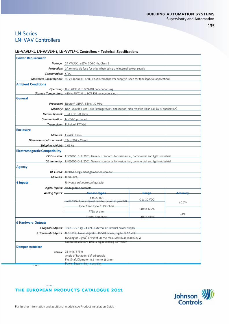
8/6/2019 Publ-6576 Prod Cat 11
http://slidepdf.com/reader/full/publ-6576-prod-cat-11 143/298
the european products catalogue 2011
For further information and additional models see Product Installation Guide
135
building automation systems
Supervisory and Automation
LN SeriesLN-VAV Controllers
LN-VAVLF-1. LN-VAVLN-1, LN-VVTLF-1 Controllers - Technical Specifications
Power Requirement
Voltage: 24 VAC/DC; ±15%, 50/60 Hz, Class 2
Protection: 3A removable fuse for triac when using the internal power supply
Consumption: 5 VA
Maximum Consumption: 10 VA (normal), or 85 VA if internal power supply is used for triac (special application)
Ambient Conditions
Operating: 0 to 70°C; 0 to 90% RH noncondensing
Storage Temperature: -20 to 70°C; 0 to 90% RH noncondensing
General
Processor: Neuron® 3150®, 8 bits, 10 MHz
Memory: Non-volatile Flash 128k (storage) (APB application, Non-volatile Flash 64k (APB application)
Media Channel: TP/FT-10; 78 Kbps
Communication: LonTalk® protocol
Transceiver: Echelon® FTT-10
Enclosure
Material: FR/ABS Resin
Dimensions (with screws): 124 x 226 x 63 mm
Shipping Weight: 1.05 kg
Electromagnetic Compatibility
CE Emission: EN61000-6-3: 2001; Generic standards for residential, commercial and light-industrial
CE Immunity: EN61000-6-1: 2001; Generic standards for residential, commercial and light-industrial
Agency
UL Listed: UL916 Energy management equipment
Material: UL94-5VA
4 Inputs Universal software configurable
Digital Inputs: Voltage free contacts
Analog Inputs: Sensor Types Range Accuracy
4 to 20 mAwith 249 ohms external resistor (wired in parallel)
0 to 10 VDC±0.5%
Type 2 and Type 3: 10k ohms-40 to 125°C
RTD: 1k ohm±1%
PT100: 100 ohms -40 to 135°C
6 Hardware Outputs
4 Digital Outputs: Triac 0.75 A @ 24 VAC, External or Internal power supply
2 Universal Outputs: 0-10 VDC linear, digital 0-10 VDC linear, digital 0-12 VDC
(Analog or Digital) or PWM 20 mA max, Maximum load 600 W
Output Resolution: 10 bits digital/analog converter
Damper Actuator
Torque 35 in·lb, 4 N·m
Angle of Rotation: 95° adjustable
Fits Shaft Diameter: 8.5 mm to 18.2 mm
Power Supply: from controller

8/6/2019 Publ-6576 Prod Cat 11
http://slidepdf.com/reader/full/publ-6576-prod-cat-11 144/298
the european products catalogue 2011
For further information and additional models see Product Installation Guide
building automation systems
136
Supervisory and Automation
LN Series
Application Specific ControllersThe Metasys® system LN Series application specific controller familyincludes the Fan Coil Unit. (FCUL), Rooftop Unit (RTUL), Heat PumpUnit (HPUL), and Unit Ventilator (UVL) controllers.
The Metasys system LN Series application specific controller can beconfigured through any LonWorks
® Network Services (LNS®) compliantsoftware with an easy-to-use LNS plug-in. The plug-in is designed tosimplify complex programming and sequencing methods by promptingthe user for the necessary configuration data.
The controllers automatically select the operation sequence from theplug-in input and output configuration and from the network variables.The Metasys system LN Series application specific controller family
is built to meet rigorous quality standards. The complete family of controllers is designed for use with any LonWorks network open andinteroperable system.
Features z LonWorks network compliant and certified - complies with LonMark
®
Interoperability guidelines Version 3.3. The controllers are based onEchelon® LonWorks technology for peer-to-peer communicationbetween controllers. Each controller qualifies for the LonMark Functional Profile for each application
z Ability to link spare Input/Output (I/O) points to other controllers onthe network; stand-alone unit or part of a network system - providesgreat network flexibility and interaction
z Robust Hardware – Features a fire retardant plastic enclosure
Ordering Codes Description
LN-RTUL-1 Rooftop Unit (RTU) Profile LonMark Certified Controller with 6 UI, 5 DO, 2 UO, and LNS Plug-in; 24 VAC
LN-FCUL-1 Fan Coil Profile LonMark Certified Controller with 6 UI, 5 DO, 2 UO, and LNS Plug-in; 24 VAC
LN-UVL-1 Unit Ventilator Profile LonMark Certified Controller with 6 UI, 5 DO, 2 UO, and LNS Plug-in; 24 VAC
LN-HPUL-1 Heat Pump Profile LonMark Certified Controller with 6 UI, 5 DO, 2 UO, and LNS Plug-in; 24 VAC
LN-PFCU-1 LonMark Fan Coil Unit Functional Profile Application Controller; 6 UI; 4 Relay Out; 4 Triac Out; LNS Plug-in; 85-265 VAC
LN-PFCUA-1LonMark Fan Coil Unit Functional Profile Application Controller; 6 UI; 4 Relay Out; 4 Triac Out; 2 Universal Output (UO); LNS Plug-in;85-265 VAC
MSEA - Metasys® System Extended Architecture

8/6/2019 Publ-6576 Prod Cat 11
http://slidepdf.com/reader/full/publ-6576-prod-cat-11 145/298
the european products catalogue 2011
For further information and additional models see Product Installation Guide
137
building automation systems
Supervisory and Automation
LN SeriesApplication Specific Controllers
LN-RTUL-1 Rooftop Unit Controller - Technical Specifications
Power
Voltage: 24 VAC, ± 15%, 50/60 Hz or 24 VAC (must be powered by a 24 VAC, Class 2 power supply)
Typical Consumption: 5 VA
Maximum Consumption: 10 VA
Protection: 1.35 Ampere Auto-Reset Fuse
Ambient Conditions
Operating Temperature: 0°C to 70°C
Storage Temperature: -20°C to 70°C
Relative Humidity: 0 to 90% Noncondensing
General
Standard: LonMark® Functional Profile Rooftop Unit #8030
Processor: Neuron® 3150®; 8 bits; 10 MHz
Memory: Flash 64K (APB application and configuration properties)
Communication: LonTalk® Protocol
Media Channel: TP/FT-10, 78 Kbps
Transceiver: Echelon® Free Topology Transceiver (FTT-10)
ElectromagneticCompatibility
CE Emission: EN61000-6-3: 2001; Generic standards for residential, commercial and light-industrial
CE Immunity: EN61000-6-1: 2001; Generic standards for residential, commercial and light-industrial
Agency
UL Listed: UL916 Energy management equipment
Material: UL94-5VA
Enclosure
Material: Metal 18 AWG
Dimensions: 127 mm x 165 mm x 33 mm
Weight: 0.67 kg
6 Inputs Universal Software Configurable
Digital: Dry Contact
Voltage: 0 - 10 VDC, Accuracy ±0.5% Current: 4 - 20 mA with 500 ohm external resistor
Input Resolution: 12 bits analog/digital converter
Sensor Types Range Accuracy
4 to 20 mAwith 500 ohms external resistor 0 to 10 VDC ±0.5%
Type 2 and Type 3: 10 k ohms -40 to 125°C
Resolution: 0.1°C
Min/Max linear configuration Potentiometer: 10 K ohm
Up to 16 point translation table configuration
7 Outputs
5 Digital Outputs: Triac 1.0 A at 24 VAC External Power Supply
2 Analog Outputs: Tri-mode Analog: 0 - 10 VDC (linear), PWM or digital 0 - 12 VDC
60 mA maximum at 12 VDC (60°C)
Maximum load 200 ohm
Auto reset fuse: 60 mA @ 60°C; 100 mA @ 20°C
Analog Output Resolution: 8 bits digital/analog converter

8/6/2019 Publ-6576 Prod Cat 11
http://slidepdf.com/reader/full/publ-6576-prod-cat-11 146/298
the european products catalogue 2011
For further information and additional models see Product Installation Guide
138
building automation systems
Supervisory and Automation
LN SeriesApplication Specific Controllers
LN-FCUL-1 Fan Coil Unit Controller - Technical Specifications
Power
Voltage: 24 VAC, ± 15%, 50/60 Hz or 24 VAC (must be powered by a 24 VAC, Class 2 power supply)
Typical Consumption: 5 VA
Maximum Consumption: 10 VA
Protection: 1.35 Ampere Auto-Reset Fuse
Ambient Conditions
Operating Temperature: 0°C to 70°C
Storage Temperature: -20°C to 70°C
Relative Humidity: 0 to 90% Noncondensing
General
Standard: LonMark® Functional Profile Rooftop Unit #8020
Processor: Neuron® 3150®; 8 bits; 10 MHz
Memory: Flash 64K (APB application and configuration properties)
Communication: LonTalk® Protocol
Media Channel: TP/FT-10, 78 Kbps
Transceiver: Echelon® Free Topology Transceiver (FTT-10)
Enclosure
Material: Metal 18 AWG
Dimensions: 127 mm x 165 mm x 33 mm
Weight: 0.67 kg
ElectromagneticCompatibility
CE Emission: EN61000-6-3: 2001; Generic standards for residential, commercial and light-industrial
CE Immunity: EN61000-6-1: 2001; Generic standards for residential, commercial and light-industrial
Agency
UL Listed: UL916 Energy management equipment
Material: UL94-5VA
6 Inputs Universal Software Configurable
Digital Inputs: Dry Contact
Input Resolution: 12 bits analog/digital converter
Sensor Types Range Accuracy
4 to 20 mAwith 500 ohms external resistor
0 to 10 VDC
±0.5%Type 2 and Type 3: 10k ohms -40 to 125°C
Resolution: 0.1°C
Min/Max linear configuration Potentiometer: 10K ohm
Up to 16 point translation table configuration
7 Outputs
5 Digital Outputs: Triac 1.0 A at 24 VAC External Power Supply
2 Analog Outputs: Tri-mode Analog: 0 - 10 VDC (linear), PWM or digital 0 - 12 VDC
60 mA maximum at 12 VDC (60°C)
Maximum load 200 ohm
Auto reset fuse: 60 mA @ 60°C; 100 mA @ 20°C
Analog Output Resolution: 8 bits digital/analog converter
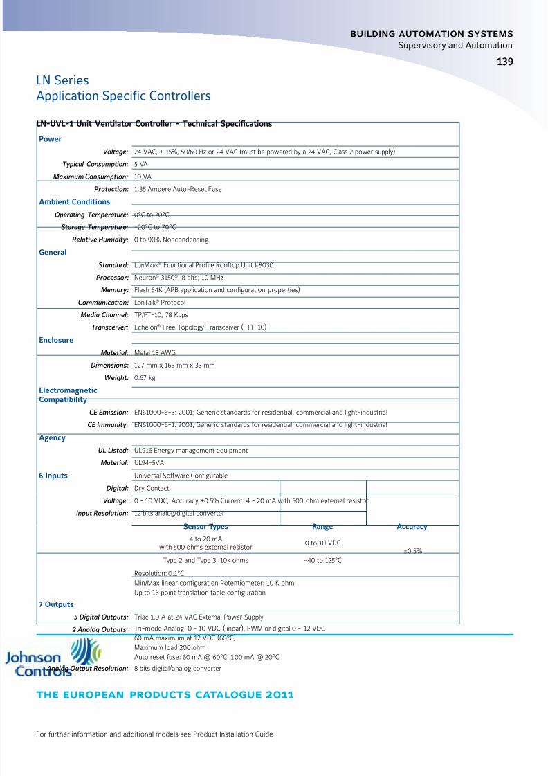
8/6/2019 Publ-6576 Prod Cat 11
http://slidepdf.com/reader/full/publ-6576-prod-cat-11 147/298
the european products catalogue 2011
For further information and additional models see Product Installation Guide
139
building automation systems
Supervisory and Automation
LN SeriesApplication Specific Controllers
LN-UVL-1 Unit Ventilator Controller - Technical Specifications
Power
Voltage: 24 VAC, ± 15%, 50/60 Hz or 24 VAC (must be powered by a 24 VAC, Class 2 power supply)
Typical Consumption: 5 VA
Maximum Consumption: 10 VA
Protection: 1.35 Ampere Auto-Reset Fuse
Ambient Conditions
Operating Temperature: 0°C to 70°C
Storage Temperature: -20°C to 70°C
Relative Humidity: 0 to 90% Noncondensing
General
Standard: LonMark® Functional Profile Rooftop Unit #8030
Processor: Neuron® 3150®; 8 bits; 10 MHz
Memory: Flash 64K (APB application and configuration properties)
Communication: LonTalk® Protocol
Media Channel: TP/FT-10, 78 Kbps
Transceiver: Echelon® Free Topology Transceiver (FTT-10)
Enclosure
Material: Metal 18 AWG
Dimensions: 127 mm x 165 mm x 33 mm
Weight: 0.67 kg
ElectromagneticCompatibility
CE Emission: EN61000-6-3: 2001; Generic standards for residential, commercial and light-industrial
CE Immunity: EN61000-6-1: 2001; Generic standards for residential, commercial and light-industrial
Agency
UL Listed: UL916 Energy management equipment
Material: UL94-5VA
6 Inputs Universal Software Configurable
Digital: Dry Contact
Voltage: 0 - 10 VDC, Accuracy ±0.5% Current: 4 - 20 mA with 500 ohm external resistor
Input Resolution: 12 bits analog/digital converter
Sensor Types Range Accuracy
4 to 20 mAwith 500 ohms external resistor 0 to 10 VDC ±0.5%
Type 2 and Type 3: 10k ohms -40 to 125°C
Resolution: 0.1°C
Min/Max linear configuration Potentiometer: 10 K ohm
Up to 16 point translation table configuration
7 Outputs
5 Digital Outputs: Triac 1.0 A at 24 VAC External Power Supply
2 Analog Outputs: Tri-mode Analog: 0 - 10 VDC (linear), PWM or digital 0 - 12 VDC
60 mA maximum at 12 VDC (60°C)
Maximum load 200 ohm
Auto reset fuse: 60 mA @ 60°C; 100 mA @ 20°C
Analog Output Resolution: 8 bits digital/analog converter
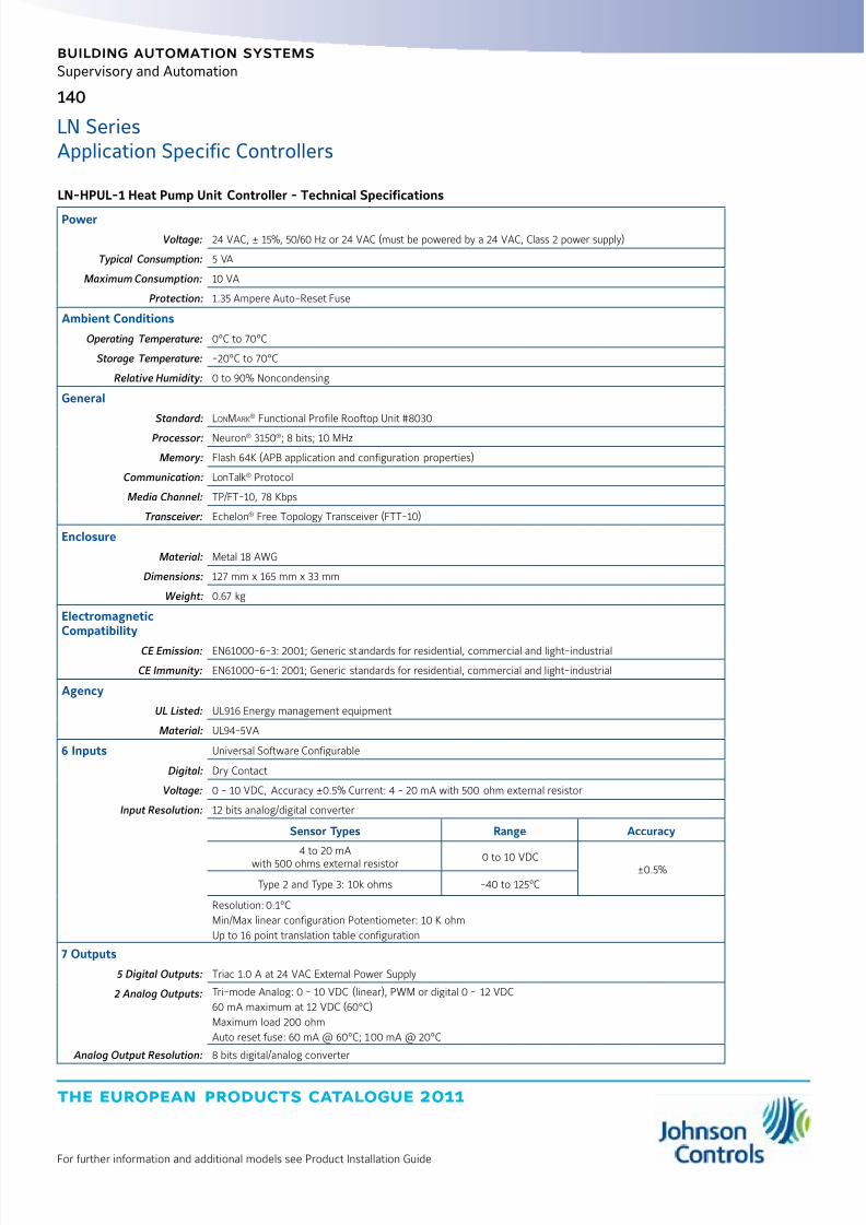
8/6/2019 Publ-6576 Prod Cat 11
http://slidepdf.com/reader/full/publ-6576-prod-cat-11 148/298
the european products catalogue 2011
For further information and additional models see Product Installation Guide
140
building automation systems
Supervisory and Automation
LN SeriesApplication Specific Controllers
LN-HPUL-1 Heat Pump Unit Controller - Technical Specifications
Power
Voltage: 24 VAC, ± 15%, 50/60 Hz or 24 VAC (must be powered by a 24 VAC, Class 2 power supply)
Typical Consumption: 5 VA
Maximum Consumption: 10 VA
Protection: 1.35 Ampere Auto-Reset Fuse
Ambient Conditions
Operating Temperature: 0°C to 70°C
Storage Temperature: -20°C to 70°C
Relative Humidity: 0 to 90% Noncondensing
General
Standard: LonMark® Functional Profile Rooftop Unit #8030
Processor: Neuron® 3150®; 8 bits; 10 MHz
Memory: Flash 64K (APB application and configuration properties)
Communication: LonTalk® Protocol
Media Channel: TP/FT-10, 78 Kbps
Transceiver: Echelon® Free Topology Transceiver (FTT-10)
Enclosure
Material: Metal 18 AWG
Dimensions: 127 mm x 165 mm x 33 mm
Weight: 0.67 kg
ElectromagneticCompatibility
CE Emission: EN61000-6-3: 2001; Generic standards for residential, commercial and light-industrial
CE Immunity: EN61000-6-1: 2001; Generic standards for residential, commercial and light-industrial
Agency
UL Listed: UL916 Energy management equipment
Material: UL94-5VA
6 Inputs Universal Software Configurable
Digital: Dry Contact
Voltage: 0 - 10 VDC, Accuracy ±0.5% Current: 4 - 20 mA with 500 ohm external resistor
Input Resolution: 12 bits analog/digital converter
Sensor Types Range Accuracy
4 to 20 mAwith 500 ohms external resistor 0 to 10 VDC ±0.5%
Type 2 and Type 3: 10k ohms -40 to 125°C
Resolution: 0.1°C
Min/Max linear configuration Potentiometer: 10 K ohm
Up to 16 point translation table configuration
7 Outputs
5 Digital Outputs: Triac 1.0 A at 24 VAC External Power Supply
2 Analog Outputs: Tri-mode Analog: 0 - 10 VDC (linear), PWM or digital 0 - 12 VDC
60 mA maximum at 12 VDC (60°C)
Maximum load 200 ohm
Auto reset fuse: 60 mA @ 60°C; 100 mA @ 20°C
Analog Output Resolution: 8 bits digital/analog converter

8/6/2019 Publ-6576 Prod Cat 11
http://slidepdf.com/reader/full/publ-6576-prod-cat-11 149/298
the european products catalogue 2011
For further information and additional models see Product Installation Guide
141
building automation systems
Supervisory and Automation
LN SeriesApplication Specific Controllers
LN-PFCUA-1 and LN-PFCU-1 Powered Fan Coil Unit (PFCU) Controllers - Technical Specifications
Power
Voltage: 85 to 265 VAC; 50-60 Hz, over voltage category II, pollution degree 2
Maximum Consumption: LN-PFCUA-1: 20 VA maximum; LN-PFCU-1: 33 VA maximum
Double-insulation devices
Protection: 2.0 A fast-acting, high breaking capacity fuse
Ambient Conditions
Operating Temperature: 0°C to 50°C - indoor use
Storage Temperature: -20°C to 70°C
Relative Humidity: 0 to 90% noncondensing
Altitude: <2,000 m
General
Processor: Neuron® 3150®; 8 bits; 10 MHz
Memory: Nonvolatile Flash 64K (APB application and configuration properties)
Communication: LonTalk® Protocol
Media Channel: TP/FT-10, 78 Kbps
Transceiver: FTX-1
Status Indicator: Green LED: power status and LON TX; Orange LED: service and LON RX
Communication Jack: LON audio jack mono 3.5 mm
Enclosure
Material: ABS PA-765A
Dimensions: 195.6 x 119.4 x 50.8 mm
Weight: 0.49 kg
ElectromagneticCompatibility
CE Emission: EN61000-6-3: 2001; Generic standards for residential, commercial and light-industrial
CE Immunity: EN61000-6-1: 2001; Generic standards for residential, commercial and light-industrial
Agency
UL Listed: UL916 Energy management equipment
Material: UL94-5VA
8 Inputs Universal Software Configurable
Digital Inputs: Voltage free contacts
Analog Voltage: 0 - 10 VDC
Analog Current: 4 to 20 mA with 249 ohm external resistor (wired in parallel)
Sensor Types Range AccuracyThermistor Type 2, Type 3, 10k ohm -40 to 125°C ±0.5°C
RTD 1k ohm -40 to 150°C±1.0°C
PT100: 100 ohms -40 to 135°C
Resolution: 0.06°C to 0.1°C (10 k ohms to 10 k ohms supported using translation table)
Potentiometer: Translation table configurable on several points, Accuracy ±0.5%
Input Resolution: 16-bit analog/digital converter
Measurement Category: CAT
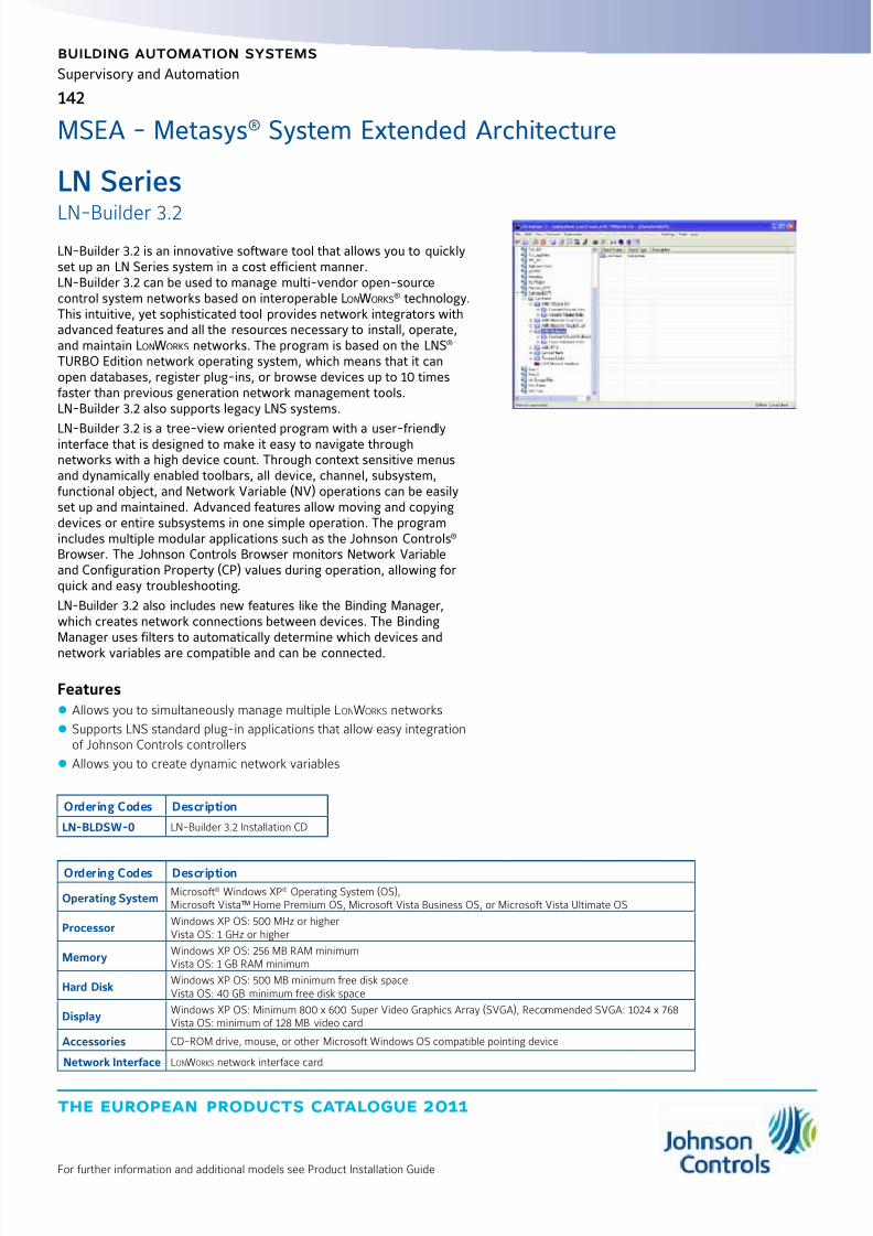
8/6/2019 Publ-6576 Prod Cat 11
http://slidepdf.com/reader/full/publ-6576-prod-cat-11 150/298
the european products catalogue 2011
For further information and additional models see Product Installation Guide
building automation systems
142
Supervisory and Automation
LN Series
LN-Builder 3.2LN-Builder 3.2 is an innovative software tool that allows you to quicklyset up an LN Series system in a cost efficient manner.LN-Builder 3.2 can be used to manage multi-vendor open-sourcecontrol system networks based on interoperable LonWorks
® technology.This intuitive, yet sophisticated tool provides network integrators withadvanced features and all the resources necessary to install, operate,and maintain LonWorks networks. The program is based on the LNS® TURBO Edition network operating system, which means that it canopen databases, register plug-ins, or browse devices up to 10 timesfaster than previous generation network management tools.LN-Builder 3.2 also supports legacy LNS systems.
LN-Builder 3.2 is a tree-view oriented program with a user-friendlyinterface that is designed to make it easy to navigate throughnetworks with a high device count. Through context sensitive menusand dynamically enabled toolbars, all device, channel, subsystem,functional object, and Network Variable (NV) operations can be easilyset up and maintained. Advanced features allow moving and copyingdevices or entire subsystems in one simple operation. The programincludes multiple modular applications such as the Johnson Controls® Browser. The Johnson Controls Browser monitors Network Variableand Configuration Property (CP) values during operation, allowing forquick and easy troubleshooting.
LN-Builder 3.2 also includes new features like the Binding Manager,which creates network connections between devices. The BindingManager uses filters to automatically determine which devices and
network variables are compatible and can be connected.
Features z Allows you to simultaneously manage multiple LonWorks networks
z Supports LNS standard plug-in applications that allow easy integrationof Johnson Controls controllers
z Allows you to create dynamic network variables
Ordering Codes Description
LN-BLDSW-0 LN-Builder 3.2 Installation CD
MSEA - Metasys® System Extended Architecture
Ordering Codes Description
Operating SystemMicrosoft® Windows XP® Operating System (OS),Microsoft Vista™ Home Premium OS, Microsoft Vista Business OS, or Microsoft Vista Ultimate OS
ProcessorWindows XP OS: 500 MHz or higherVista OS: 1 GHz or higher
MemoryWindows XP OS: 256 MB RAM minimumVista OS: 1 GB RAM minimum
Hard DiskWindows XP OS: 500 MB minimum free disk spaceVista OS: 40 GB minimum free disk space
DisplayWindows XP OS: Minimum 800 x 600 Super Video Graphics Array (SVGA), Recommended SVGA: 1024 x 768Vista OS: minimum of 128 MB video card
Accessories CD-ROM drive, mouse, or other Microsoft Windows OS compatible pointing device
Network Interface LonWorks network interface card

8/6/2019 Publ-6576 Prod Cat 11
http://slidepdf.com/reader/full/publ-6576-prod-cat-11 151/298
the european products catalogue 2011
Manufacturer reserved the rights to change specifications without prior notice
index
building automation systems
Electronic Control DevicesFacility Explorer Controllers Platform
FX03 Configurable Terminal Unit Controller 145
FX06
Field Controller
147
FX07 150
FX14 154FX15 158
FX15 Universal Field Controller 162
FX16 Master Controller 165
MD20 Master Display 169
MUI Medium User Interface 172
XM07 and XM14 FX Input/Output (I/O) Modules 173
LP-XT Extension Module and LP-XP - Expansion Modules 179
FX Tools Pro 180
Metasys ® Field Controllers L on W orks ® Compatible
AD-FCC and AD-FCD Fan Coil Control Solution 181
AD-IRC Integrated Room Control Solution 183
DX-9121 Digital Controller N2E 185
DX-9200 Digital Controller 188
Metasys ® Field Controllers N2 Bus
DX-9100 Extended Digital Controller 191
XTM-905 / XT-9100and XP / XT-910x
Extension Module and Expansion Modules 194
VMA1400 Variable Air Volume Controller 195

8/6/2019 Publ-6576 Prod Cat 11
http://slidepdf.com/reader/full/publ-6576-prod-cat-11 152/298
the european products catalogue 2011
Manufacturer reserved the rights to change specifications without prior notice
Notes
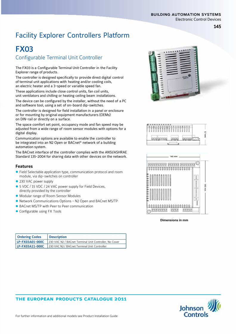
8/6/2019 Publ-6576 Prod Cat 11
http://slidepdf.com/reader/full/publ-6576-prod-cat-11 153/298
the european products catalogue 2011
For further information and additional models see Product Installation Guide
145
building automation systems
145
Electronic Control Devices
FX03
Configurable Terminal Unit ControllerThe FX03 is a Configurable Terminal Unit Controller in the FacilityExplorer range of products.
The controller is designed specifically to provide direct digital controlof terminal unit applications with heating and/or cooling coils,an electric heater and a 3-speed or variable speed fan.
These applications include close control units, fan coil units,unit ventilators and chilling or heating ceiling beam installations.
The device can be configured by the installer, without the need of a PCand software tool, using a set of on-board dip-switches.
The controller is designed for field installation in a panel or enclosureor for mounting by original equipment manufacturers (OEMs)on DIN-rail or directly on a surface.
The space comfort set point, occupancy mode and fan speed may beadjusted from a wide range of room sensor modules with options for adigital display.
Communication options are available to enable the controller tobe integrated into an N2 Open or BACnet® network of a buildingautomation system.
The BACnet interface of the controller complies with the ANSI/ASHRAEStandard 135-2004 for sharing data with other devices on the network.
Features z Field Selectable application type, communication protocol and room
module, via dip-switches on controller z 230 VAC power supply
z 5 VDC / 15 VDC / 24 VAC power supply for Field Devices,directly provided by the controller
z Modular range of Room Sensor Modules
z Network Communications Options - N2 Open and BACnet MS/TP
z BACnet MS/TP with Peer to Peer communication
z Configurable using FX Tools
Dimensions in mm
Ordering Codes Description
LP-FX03A01-000C 230 VAC N2 / BACnet Terminal Unit Controller, No Cover
LP-FX03A11-000C 230 VAC N2 / BACnet Terminal Unit Controller
Facility Explorer Controllers Platform
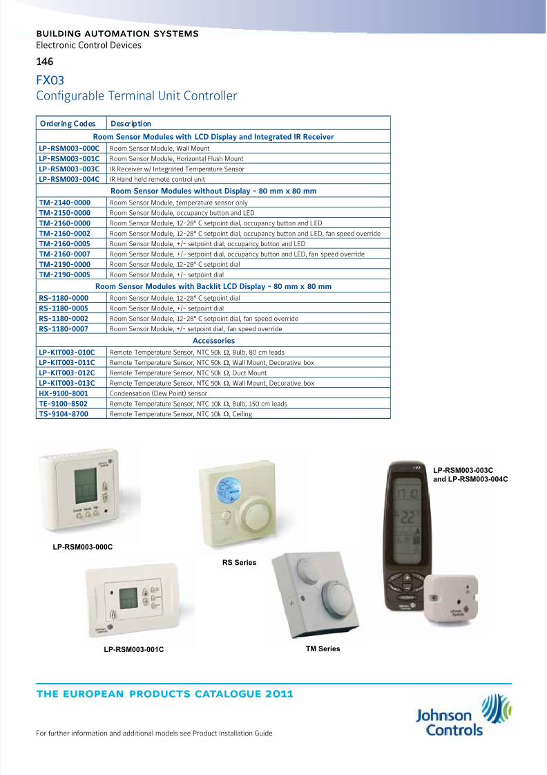
8/6/2019 Publ-6576 Prod Cat 11
http://slidepdf.com/reader/full/publ-6576-prod-cat-11 154/298
the european products catalogue 2011
For further information and additional models see Product Installation Guide
146
building automation systems
Electronic Control Devices
FX03Configurable Terminal Unit Controller
Ordering Codes Description
Room Sensor Modules with LCD Display and Integrated IR ReceiverLP-RSM003-000C Room Sensor Module, Wall Mount
LP-RSM003-001C Room Sensor Module, Horizontal Flush Mount
LP-RSM003-003C IR Receiver w/ Integrated Temperature Sensor
LP-RSM003-004C IR Hand held remote control unit
Room Sensor Modules without Display - 80 mm x 80 mm
TM-2140-0000 Room Sensor Module, temperature sensor only
TM-2150-0000 Room Sensor Module, occupancy button and LED
TM-2160-0000 Room Sensor Module, 12-28° C setpoint dial, occupancy button and LED
TM-2160-0002 Room Sensor Module, 12-28° C setpoint dial, occupancy button and LED, fan speed override
TM-2160-0005 Room Sensor Module, +/- setpoint dial, occupancy button and LED
TM-2160-0007 Room Sensor Module, +/- setpoint dial, occupancy button and LED, fan speed override
TM-2190-0000 Room Sensor Module, 12-28° C setpoint dial
TM-2190-0005 Room Sensor Module, +/- setpoint dial
Room Sensor Modules with Backlit LCD Display - 80 mm x 80 mm
RS-1180-0000 Room Sensor Module, 12-28° C setpoint dial
RS-1180-0005 Room Sensor Module, +/- setpoint dial
RS-1180-0002 Room Sensor Module, 12-28° C setpoint dial, fan speed override
RS-1180-0007 Room Sensor Module, +/- setpoint dial, fan speed override
Accessories
LP-KIT003-010C Remote Temperature Sensor, NTC 50k W, Bulb, 80 cm leads
LP-KIT003-011C Remote Temperature Sensor, NTC 50k W, Wall Mount, Decorative box
LP-KIT003-012C Remote Temperature Sensor, NTC 50k W, Duct Mount
LP-KIT003-013C Remote Temperature Sensor, NTC 50k W, Wall Mount, Decorative box
HX-9100-8001 Condensation (Dew Point) sensor
TE-9100-8502 Remote Temperature Sensor, NTC 10kW
, Bulb, 150 cm leadsTS-9104-8700 Remote Temperature Sensor, NTC 10k W, Ceiling
LP-RSM003-000C
LP-RSM003-001C
LP-RSM003-003C
and LP-RSM003-004C
RS Series
TM Series

8/6/2019 Publ-6576 Prod Cat 11
http://slidepdf.com/reader/full/publ-6576-prod-cat-11 155/298
the european products catalogue 2011
For further information and additional models see Product Installation Guide
147
building automation systems
147
Electronic Control Devices
85
70
44
77
28
95
83
Dimensions in mm
The FX06 is a Compact Field Controller in the Facility Explorer rangeof products. The controller is designed specifically for commercialHeating, Ventilating, and Air Conditioning (HVAC) and Refrigerationapplications. The FX06 is a high performance controller with a powerful
16-bit microprocessor and state-of-the-art software for the precisecontrol of many types of mechanical and electrical equipment.The FX06 controller has 17 physical inputs and outputs and supportsa wide range of temperature sensors and actuating devices.Active sensors for the measurement of humidity, pressure, andother variables are also supported. The FX06 has a state-of-the-art LCD display including a set of graphic status icons used in themost common HVAC/R applications. The FX06 controller is availablewith plug-in communication modules to enable the controller tobe integrated into an N2 Open or LonWorks
® compatible buildingautomation system. In addition the FX06 field controller also featurescommunications services to transmit event notification messagesvia Short Messaging Service (SMS). The FX06 field controller is fullyconfigurable or programmable, using the FX Tools software package,for a wide range of commercial HVACR applications.
Features z Modular Network communication options
z On-Board Real Time Clockz Freely programmable or configurable using FX Tools software package
z Resistance Temperature Dependent (RTD - PT1000 and A99), Negative
Temperature Coefficient (NTC 10K) or Active Temperature Sensor Inputs z Integral Liquid Crystal Display (LCD) User Interface with Control Buttonsand Graphic Icons
z Models with Various Output Configurations of Solid-State Triacs andRelay Contacts
Ordering Codes Description
LP-FX06P00-000C 4 AIs, 5 BIs, 2 AOs (0-10V), 6 BOs Relays, no Communication Module
LP-FX06P01-000C 4 AIs, 5 BIs, 2 AOs (0-10V), 6 BOs Relays, N2 Open module, 1 cable set
LP-FX06P02-000C 4 AIs, 5 BIs, 2 AOs (0-10V), 6 BOs Relays, LonWorks® module, 1 cable set
LP-FX06P03-000C 4 AIs, 5 BIs, 2 AOs (0-10V), 6 BOs Relays, RS-232 module, 1 cable set
LP-FX06P10-000C 4 AIs, 5 BIs, 2 AOs (1 0-10V,1 PWM (Factory setting), 6 BOs Relays, no Communication Module
LP-FX06P11-000C 4 AIs, 5 BIs, 2 AOs (1 0-10V,1 PWM (Factory setting), 6 BOs Relays, N2 Open module, 1 cable setLP-FX06P12-000C 4 AIs, 5 BIs, 2 AOs (1 0-10V,1 PWM (Factory setting), 6 BOs Relays, LonWorks
® module, 1 cable set
LP-FX06P13-000C 4 AIs, 5 BIs, 2 AOs (1 0-10V,1 PWM (Factory setting), 6 BOs Relays, RS-232 module, 1 cable set
LP-FX06P20-000C 4 AIs, 5 BIs, 2 AOs (0-10V), 6 BOs (4 Relays, 2 Triacs), no Communication Module
LP-FX06P21-000C 4 AIs, 5 BIs, 2 AOs (0-10V), 6 BOs (4 Relays, 2 Triacs), N2 Open module, 1 cable set
LP-FX06P22-000C 4 AIs, 5 BIs, 2 AOs (0-10V), 6 BOs (4 Relays, 2 Triacs), LonWorks® module, 1 cable set
LP-FX06P23-000C 4 AIs, 5 BIs, 2 AOs (0-10V), 6 BOs (4 Relays, 2 Triacs), RS-232 module, 1 cable set
LP-FX06P30-000C 4 AIs, 5 BIs, 2 AOs (0-10V), 6 BOs (3 Intrlck Relays, 1 free Relay, 2 Triacs), no Communication Module
LP-FX06P31-000C 4 AIs, 5 BIs, 2 AOs (0-10V), 6 BOs (3 Intrlck Relays, 1 free Relay, 2 Triacs), N2 Open module, 1 cable set
LP-FX06P32-000C 4 AIs, 5 BIs, 2 AOs (0-10V), 6 BOs (3 Intrlck Relays, 1 free Relay, 2 Triacs), LonWorks® module, 1 cable set
LP-FX06P33-000C 4 AIs, 5 BIs, 2 AOs (0-10V), 6 BOs (3 Intrlck Relays, 1 free Relay, 2 Triacs) RS-232 module, 1 cable set
FX06
Field Controller
Facility Explorer Controllers Platform
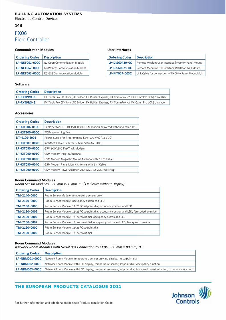
8/6/2019 Publ-6576 Prod Cat 11
http://slidepdf.com/reader/full/publ-6576-prod-cat-11 156/298
the european products catalogue 2011
For further information and additional models see Product Installation Guide
148
building automation systems
Electronic Control Devices
FX06Field Controller
User Interfaces
Ordering Codes Description
LP-DIS60P20-0C Remote Medium User Interface (MUI) for Panel Mount
LP-DIS60P21-0C Remote Medium User Interface (MUI) for Wall Mount
LP-KIT007-005C Link Cable for connection of FX06 to Panel Mount MUI
Software
Ordering Codes Description
LP-FXTPRO-0 FX Tools Pro CD-Rom (FX Builder, FX Builder Express, FX CommPro N2, FX CommPro LON) New User
LP-FXTPRO-6 FX Tools Pro CD-Rom (FX Builder, FX Builder Express, FX CommPro N2, FX CommPro LON) Upgrade
Accessories
Ordering Codes Description
LP-KIT006-010C Cable set for LP-FX06Px0-000C OEM models delivered without a cable set.
LP-KIT100-000C FX Programming Key
DT-9100-8901 Power Supply for Programming Key: 230 VAC / 12 VDC
LP-KIT007-002C Interface Cable 1.5 m for GSM modem to FX06
LP-KIT090-000C GSM 900/1800 FastTrack Modem
LP-KIT090-001C GSM Modem Plug-In Antenna
LP-KIT090-003C GSM Modem Magnetic Mount Antenna with 2.5 m Cable
LP-KIT090-004C GSM Modem Panel Mount Antenna with 5 m Cable
LP-KIT090-005C GSM Modem Power Adapter, 230 VAC / 12 VDC, Wall Plug
Room Command ModulesRoom Sensor Modules – 80 mm x 80 mm, °C (TM Series without Display)
Ordering Codes Description
TM-2140-0000 Room Sensor Module, temperature sensor only
TM-2150-0000 Room Sensor Module, occupancy button and LED
TM-2160-0000 Room Sensor Module, 12-28 °C setpoint dial, occupancy button and LED
TM-2160-0002 Room Sensor Module, 12-28 °C setpoint dial, occupancy button and LED, fan speed override
TM-2160-0005 Room Sensor Module, +/- setpoint dial, occupancy button and LED
TM-2160-0007 Room Sensor Module, +/- setpoint dial, occupancy button and LED, fan speed override
TM-2190-0000 Room Sensor Module, 12-28 °C setpoint dial
TM-2190-0005 Room Sensor Module, +/- setpoint dial
Room Command ModulesNetwork Room Modules with Serial Bus Connection to FX06 – 80 mm x 80 mm, °C
Ordering Codes Description
LP-NRM001-000C Network Room Module, temperature sensor only, no display, no setpoint dial
LP-NRM002-000C Network Room Module with LCD display, temperature sensor, setpoint dial, occupancy function
LP-NRM003-000C Network Room Module with LCD display, temperature sensor, setpoint dial, fan speed override button, occupancy function
Communication Modules
Ordering Codes Description
LP-NET061-000C N2 Open Communication Module
LP-NET062-000C LonWorks® Communication Module
LP-NET063-000C RS-232 Communication Module

8/6/2019 Publ-6576 Prod Cat 11
http://slidepdf.com/reader/full/publ-6576-prod-cat-11 157/298
the european products catalogue 2011
For further information and additional models see Product Installation Guide
149
building automation systems
Electronic Control Devices
FX06Field Controller
Technical Specifications
Power Requirements 24 VAC/VDC ±15%, 50/60 Hz – SELV (Europe) – Class 2 North America
Power Consumption 7 VA
Protection Class Front Plate: IP55
Rear: IP20
Ambient Operating Conditions -20 to 50 °C
10 to 95% RH (non condensing)
Ambient Storage Conditions -40 to 70 °C
10 to 95% RH (non condensing)
Display Range and Resolution -999 to 999 or –99.9 to 99.9 (4 digits in each of two rows)
Digital Inputs Voltage free contacts
Transition counter function at 50 Hz (minimum 10 ms ON and minimum 10 ms OFF)
Analog Inputs and Accuracyat 20 °C Ambient
(sensor error not included)
Not isolated. Software configurable.
Sensor Type Range AccuracyA99 -40 to 100 °C ±0.5 °C
NTC K10 -20 to 70 °C ±0.5 °C
PT1000 Extended -40 to 160 °C ±0.5 °C
Ni1000 -40 to 120 °C ±0.5 °C
Active 0...10 V 0..10 VDC ±0.05 VDC
Active Ratio-metric 0.5 to 4.5 VDC ±0.05 VDC
Analog Outputs 0...10 VDC, 3 mA, not isolated for actuating and control devices.
Pulse Width Modulation (PWM) Signal at 100 Hz cycle frequency
Relay Outputs Dielectric test voltage on open relay contact: 1,000 VAC RMS
Maximum relay switching rate at nominal load: 6 operations / min
Average relay contact life: 30,000 operations at maximum load.
Digital Outputs forSelected Models
Model Channel Type Remark/Application
FX06P0x / P1x DO1 – DO6SPST 3(1)A, 250 VAC
power relayEach relay contact is independent with its own commonterminal.
FX06P2x / P3x
DO1, DO2 0.5A / 24 VAC triacs 3-point incremental actuators, thermal actuators, etc
DO3 – DO6SPST 3(1)A, 250 VAC
power relay
On the FX06P2x models, each relay contact isindependent with its own common terminal.
On the FX06P3x model, DO4, DO5 and DO6 relays arephysically interlocked, i.e. only one output can be closedat one time.
Application: 3-speed fan motors.
The DO3 relay is independent.
Dimensions (H x W x D) 44 x 85 x 95 - 52 x 85 x 95 with Communication Module
CE Compliance 2004/108/EC: EN 61000-6-2:2007, EN 61000-6-3:2007 - 2006/95/EC: EN 60730-1:2001
UL Compliance UL916
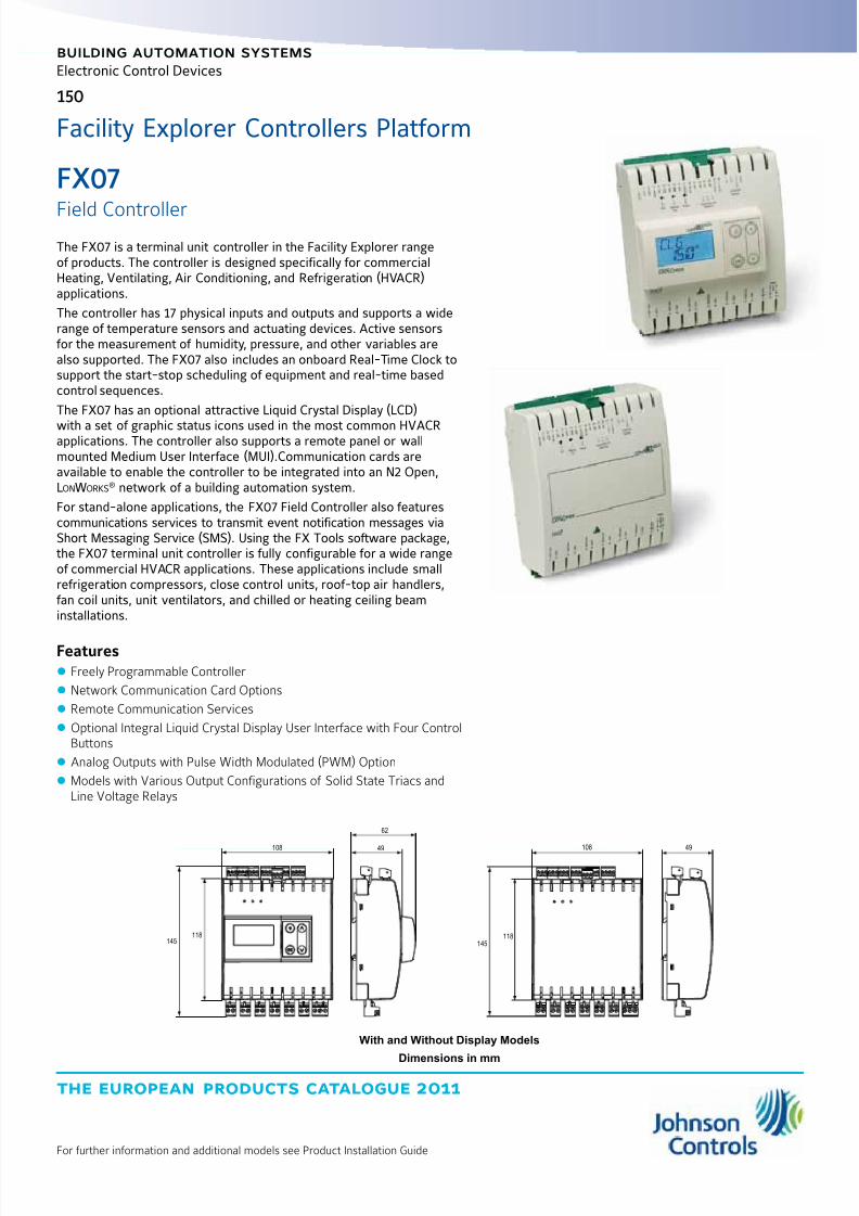
8/6/2019 Publ-6576 Prod Cat 11
http://slidepdf.com/reader/full/publ-6576-prod-cat-11 158/298
the european products catalogue 2011
For further information and additional models see Product Installation Guide
building automation systems
150
Electronic Control Devices
The FX07 is a terminal unit controller in the Facility Explorer rangeof products. The controller is designed specifically for commercialHeating, Ventilating, Air Conditioning, and Refrigeration (HVACR)applications.
The controller has 17 physical inputs and outputs and supports a widerange of temperature sensors and actuating devices. Active sensorsfor the measurement of humidity, pressure, and other variables arealso supported. The FX07 also includes an onboard Real-Time Clock tosupport the start-stop scheduling of equipment and real-time basedcontrol sequences.
The FX07 has an optional attractive Liquid Crystal Display (LCD)
with a set of graphic status icons used in the most common HVACRapplications. The controller also supports a remote panel or wallmounted Medium User Interface (MUI).Communication cards areavailable to enable the controller to be integrated into an N2 Open,LonWorks
® network of a building automation system.
For stand-alone applications, the FX07 Field Controller also featurescommunications services to transmit event notification messages viaShort Messaging Service (SMS). Using the FX Tools software package,the FX07 terminal unit controller is fully configurable for a wide rangeof commercial HVACR applications. These applications include smallrefrigeration compressors, close control units, roof-top air handlers,fan coil units, unit ventilators, and chilled or heating ceiling beaminstallations.
Features z Freely Programmable Controller
z Network Communication Card Options
z Remote Communication Services
z Optional Integral Liquid Crystal Display User Interface with Four ControlButtons
z Analog Outputs with Pulse Width Modulated (PWM) Option
z Models with Various Output Configurations of Solid State Triacs andLine Voltage Relays
108
145118
62
49
145
118
108 49
With and Without Display Models
Dimensions in mm
FX07
Field Controller
Facility Explorer Controllers Platform
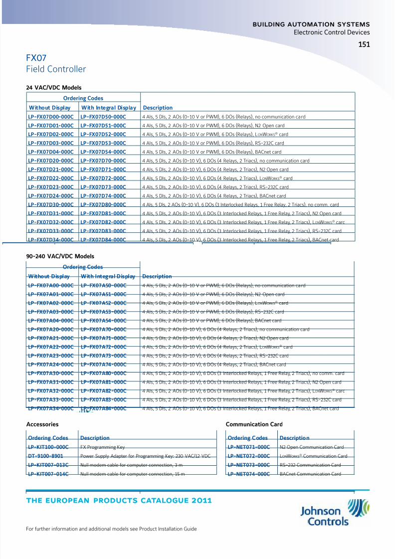
8/6/2019 Publ-6576 Prod Cat 11
http://slidepdf.com/reader/full/publ-6576-prod-cat-11 159/298
the european products catalogue 2011
For further information and additional models see Product Installation Guide
151
building automation systems
Electronic Control Devices
90-240 VAC/VDC Models
Ordering Codes
DescriptionWithout Display With Integral Display
LP-FX07A00-000C LP-FX07A50-000C 4 AIs, 5 DIs, 2 AOs (0-10 V or PWM), 6 DOs (Relays), no communication card
LP-FX07A01-000C LP-FX07A51-000C 4 AIs, 5 DIs, 2 AOs (0-10 V or PWM), 6 DOs (Relays), N2 Open card
LP-FX07A02-000C LP-FX07A52-000C 4 AIs, 5 DIs, 2 AOs (0-10 V or PWM), 6 DOs (Relays), LonWorks® card
LP-FX07A03-000C LP-FX07A53-000C 4 AIs, 5 DIs, 2 AOs (0-10 V or PWM), 6 DOs (Relays), RS-232C card
LP-FX07A04-000C LP-FX07A54-000C 4 AIs, 5 DIs, 2 AOs (0-10 V or PWM), 6 DOs (Relays), BACnet card
LP-FX07A20-000C LP-FX07A70-000C 4 AIs, 5 DIs, 2 AOs (0-10 V), 6 DOs (4 Relays, 2 Triacs), no communication card
LP-FX07A21-000C LP-FX07A71-000C 4 AIs, 5 DIs, 2 AOs (0-10 V), 6 DOs (4 Relays, 2 Triacs), N2 Open card
LP-FX07A22-000C LP-FX07A72-000C 4 AIs, 5 DIs, 2 AOs (0-10 V), 6 DOs (4 Relays, 2 Triacs), LonWorks® card
LP-FX07A23-000C LP-FX07A73-000C 4 AIs, 5 DIs, 2 AOs (0-10 V), 6 DOs (4 Relays, 2 Triacs), RS-232C card
LP-FX07A24-000C LP-FX07A74-000C 4 AIs, 5 DIs, 2 AOs (0-10 V), 6 DOs (4 Relays, 2 Triacs), BACnet card
LP-FX07A30-000C LP-FX07A80-000C 4 AIs, 5 DIs, 2 AOs (0-10 V), 6 DOs (3 Interlocked Relays, 1 Free Relay, 2 Triacs), no comm. card
LP-FX07A31-000C LP-FX07A81-000C 4 AIs, 5 DIs, 2 AOs (0-10 V), 6 DOs (3 Interlocked Relays, 1 Free Relay, 2 Triacs), N2 Open card
LP-FX07A32-000C LP-FX07A82-000C 4 AIs, 5 DIs, 2 AOs (0-10 V), 6 DOs (3 Interlocked Relays, 1 Free Relay, 2 Triacs), LonWorks
®
cardLP-FX07A33-000C LP-FX07A83-000C 4 AIs, 5 DIs, 2 AOs (0-10 V), 6 DOs (3 Interlocked Relays, 1 Free Relay, 2 Triacs), RS-232C card
LP-FX07A34-000C LP-FX07A84-000C 4 AIs, 5 DIs, 2 AOs (0-10 V), 6 DOs (3 Interlocked Relays, 1 Free Relay, 2 Triacs), BACnet card
Communication Card
Ordering Codes Description
LP-NET071-000C N2 Open Communication Card
LP-NET072-000C LonWorks® Communication Card
LP-NET073-000C RS-232 Communication Card
LP-NET074-000C BACnet Communication Card
Accessories
Ordering Codes Description
LP-KIT100-000C FX Programming Key
DT-9100-8901 Power Supply Adapter for Programming Key: 230 VAC/12 VDC
LP-KIT007-013C Null modem cable for computer connection, 3 m
LP-KIT007-014C Null modem cable for computer connection, 15 m
24 VAC/VDC Models
Ordering CodesDescriptionWithout Display With Integral Display
LP-FX07D00-000C LP-FX07D50-000C 4 AIs, 5 DIs, 2 AOs (0-10 V or PWM), 6 DOs (Relays), no communication card
LP-FX07D01-000C LP-FX07D51-000C 4 AIs, 5 DIs, 2 AOs (0-10 V or PWM), 6 DOs (Relays), N2 Open card
LP-FX07D02-000C LP-FX07D52-000C 4 AIs, 5 DIs, 2 AOs (0-10 V or PWM), 6 DOs (Relays), LonWorks® card
LP-FX07D03-000C LP-FX07D53-000C 4 AIs, 5 DIs, 2 AOs (0-10 V or PWM), 6 DOs (Relays), RS-232C card
LP-FX07D04-000C LP-FX07D54-000C 4 AIs, 5 DIs, 2 AOs (0-10 V or PWM), 6 DOs (Relays), BACnet card
LP-FX07D20-000C LP-FX07D70-000C 4 AIs, 5 DIs, 2 AOs (0-10 V), 6 DOs (4 Relays, 2 Triacs), no communication card
LP-FX07D21-000C LP-FX07D71-000C 4 AIs, 5 DIs, 2 AOs (0-10 V), 6 DOs (4 Relays, 2 Triacs), N2 Open card
LP-FX07D22-000C LP-FX07D72-000C 4 AIs, 5 DIs, 2 AOs (0-10 V), 6 DOs (4 Relays, 2 Triacs), LonWorks® card
LP-FX07D23-000C LP-FX07D73-000C 4 AIs, 5 DIs, 2 AOs (0-10 V), 6 DOs (4 Relays, 2 Triacs), RS-232C card
LP-FX07D24-000C LP-FX07D74-000C 4 AIs, 5 DIs, 2 AOs (0-10 V), 6 DOs (4 Relays, 2 Triacs), BACnet cardLP-FX07D30-000C LP-FX07D80-000C 4 AIs, 5 DIs, 2 AOs (0-10 V), 6 DOs (3 Interlocked Relays, 1 Free Relay, 2 Triacs), no comm. card
LP-FX07D31-000C LP-FX07D81-000C 4 AIs, 5 DIs, 2 AOs (0-10 V), 6 DOs (3 Interlocked Relays, 1 Free Relay, 2 Triacs), N2 Open card
LP-FX07D32-000C LP-FX07D82-000C 4 AIs, 5 DIs, 2 AOs (0-10 V), 6 DOs (3 Interlocked Relays, 1 Free Relay, 2 Triacs), LonWorks® card
LP-FX07D33-000C LP-FX07D83-000C 4 AIs, 5 DIs, 2 AOs (0-10 V), 6 DOs (3 Interlocked Relays, 1 Free Relay, 2 Triacs), RS-232C card
LP-FX07D34-000C LP-FX07D84-000C 4 AIs, 5 DIs, 2 AOs (0-10 V), 6 DOs (3 Interlocked Relays, 1 Free Relay, 2 Triacs), BACnet card
FX07Field Controller
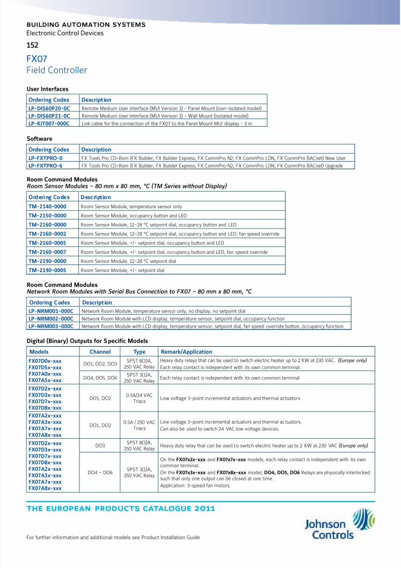
8/6/2019 Publ-6576 Prod Cat 11
http://slidepdf.com/reader/full/publ-6576-prod-cat-11 160/298
the european products catalogue 2011
For further information and additional models see Product Installation Guide
152
building automation systems
Electronic Control Devices
User Interfaces
Ordering Codes DescriptionLP-DIS60P20-0C Remote Medium User Interface (MUI Version 3) - Panel Mount (non-isolated model)
LP-DIS60P21-0C Remote Medium User Interface (MUI Version 3) - Wall Mount (isolated model)
LP-KIT007-000C Link cable for the connection of the FX07 to the Panel Mount MUI display - 3 m
Software
Ordering Codes Description
LP-FXTPRO-0 FX Tools Pro CD-Rom (FX Builder, FX Builder Express, FX CommPro N2, FX CommPro LON, FX CommPro BACnet) New User
LP-FXTPRO-6 FX Tools Pro CD-Rom (FX Builder, FX Builder Express, FX CommPro N2, FX CommPro LON, FX CommPro BACnet) Upgrade
Room Command ModulesRoom Sensor Modules – 80 mm x 80 mm, °C (TM Series without Display)
Ordering Codes DescriptionTM-2140-0000 Room Sensor Module, temperature sensor only
TM-2150-0000 Room Sensor Module, occupancy button and LED
TM-2160-0000 Room Sensor Module, 12-28 °C setpoint dial, occupancy button and LED
TM-2160-0002 Room Sensor Module, 12-28 °C setpoint dial, occupancy button and LED, fan speed override
TM-2160-0005 Room Sensor Module, +/- setpoint dial, occupancy button and LED
TM-2160-0007 Room Sensor Module, +/- setpoint dial, occupancy button and LED, fan speed override
TM-2190-0000 Room Sensor Module, 12-28 °C setpoint dial
TM-2190-0005 Room Sensor Module, +/- setpoint dial
Room Command ModulesNetwork Room Modules with Serial Bus Connection to FX07 – 80 mm x 80 mm, °C
Ordering Codes Description
LP-NRM001-000C Network Room Module, temperature sensor only, no display, no setpoint dial
LP-NRM002-000C Network Room Module with LCD display, temperature sensor, setpoint dial, occupancy function
LP-NRM003-000C Network Room Module with LCD display, temperature sensor, setpoint dial, fan speed override button, occupancy function
Digital (Binary) Outputs for Specific Models
Models Channel Type Remark/Application
FX07D0x-xxxFX07D5x-xxxFX07A0x-xxxFX07A5x-xxx
DO1, DO2, DO3SPST 8(3)A,
250 VAC RelayHeavy duty relays that can be used to switch electric heater up to 2 KW at 230 VAC. (Europe only)
Each relay contact is independent with its own common terminal.
DO4, DO5, DO6SPST 3(1)A,
250 VAC RelayEach relay contact is independent with its own common terminal
FX07D2x-xxxFX07D3x-xxxFX07D7x-xxxFX07D8x-xxx
DO1, DO20.5A/24 VAC
Triacs Low voltage 3-point incremental actuators and thermal actuators
FX07A2x-xxxFX07A3x-xxxFX07A7x-xxxFX07A8x-xxx
DO1, DO20.5A / 250 VAC
TriacsLine voltage 3-point incremental actuators and thermal actuators.
Can also be used to switch 24 VAC low voltage devices.
FX07D2x-xxxFX07D3x-xxxFX07D7x-xxxFX07D8x-xxxFX07A2x-xxxFX07A3x-xxxFX07A7x-xxxFX07A8x-xxx
DO3SPST 8(3)A,
250 VAC RelayHeavy duty relay that can be used to switch electric heater up to 2 KW at 230 VAC (Europe only)
DO4 – DO6SPST 3(1)A,
250 VAC Relay
On the FX07x2x-xxx and FX07x7x-xxx models, each relay contact is independent with its owncommon terminal.
On the FX07x3x-xxx and FX07x8x-xxx model, DO4, DO5, DO6 Relays are physically interlockedsuch that only one output can be closed at one time.
Application: 3-speed fan motors.
FX07Field Controller

8/6/2019 Publ-6576 Prod Cat 11
http://slidepdf.com/reader/full/publ-6576-prod-cat-11 161/298
the european products catalogue 2011
For further information and additional models see Product Installation Guide
153
building automation systems
Electronic Control Devices
Technical Specifications
Product Codes LP-FX07xxx-xxx
Power Supply Requirements LP-FX07Dxx-xxx: 24 VAC/DC ±15%, 50/60 Hz - SELV (Europe) - Class 2 North America
LP-FX07Axx-xxx: 90 to 240 VAC, 50/60 Hz
Power Consumption LP-FX07Dxx-xxx: 9 VA maximum
LP-FX07Axx-xxx: 17 VA maximum
Protection Class IP20 CEI/EN60529
Ambient Operating Conditions -40 °C to 50 °C, 10 to 95% RH (non condensing)
Note that the integral user interface does not operate below -20 °C
Ambient Storage Conditions -40 °C to +70 °C, 10 to 95% RH (non condensing)
Dimensions (H x W x D) 145 mm including terminals x 108 mm x 49 mm - 62 mm with display
Weight (with package) 0.60 kg
Integral LCD Display Resolution -999 to 999 or –99.9 to 99.9
Digital Inputs Voltage free contactsTransition counter function at 50 Hz(minimum 10 ms ON and minimum 10 ms OFF)
Analog Inputs and Accuracyat 20 °C Ambient(sensor error not included)
Not isolated. Software configurable.
Sensor Type Range Accuracy
A99 -40 to 100 °C ±0.5 °C
NTC K10 -20 to 70 °C ±0.5 °C
PT1000 Extended -40 to 160 °C ±0.5 °C
Ni1000 -40 to 120 °C ±0.5 °C
Active 0...10 V 0..10 VDC ±0.05 VDC
Active Ratio-metric 0.5 to 4.5 VDC ±0.05 VDC
Analog Outputs 0...10 VDC, 3 mA, not isolated for actuating and control devices.Pulse Width Modulation (PWM) Signal at 100 Hz cycle frequency
Relay Outputs Dielectric test voltage on open relay contact: 1,000 VAC RMS
Maximum relay switching rate at nominal load: 6 operations / min
Average relay contact life: 30,000 operations at maximum load.
Connection Terminals foroutputs and Power Supply
Screw terminals for max 2 x 1.5 mm2 (AWG16) wires, included in the package.
Connection Terminals for inputsand LON/N2 Open/BACnet Bus
Screw terminals for max. 1 x 1.5 mm2 (AWG16) wires or 2 x Belden cable,
2-core twisted pair with shield ≥ 0.8 mm (AWG20), included in the package
CE Compliance 2004/108/EC: EN 61000-6-2:2007, EN 61000-6-3:2007 - 2006/95/EC: EN 60730-1:2001
UL Compliance UL916
FX07Field Controller
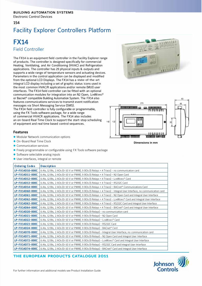
8/6/2019 Publ-6576 Prod Cat 11
http://slidepdf.com/reader/full/publ-6576-prod-cat-11 162/298
the european products catalogue 2011
For further information and additional models see Product Installation Guide
building automation systems
154
Electronic Control Devices
The FX14 is an equipment field controller in the Facility Explorer rangeof products. The controller is designed specifically for commercialHeating, Ventilating, and Air Conditioning (HVAC) and Refrigerationapplications. The controller has 29 physical inputs & outputs andsupports a wide range of temperature sensors and actuating devices.Parameters in the control application can be displayed and modifiedfrom the optional LCD Displays. The FX14 has a state-of-the-artintegral LCD display including a set of graphic status icons used inthe most common HVAC/R applications and/or remote (MUI) userinterfaces. The FX14 field controller can be fitted with an optionalcommunication modules for integration into an N2 Open, LonWorks
® or Bacnet® compatible Building Automation System. The FX14 alsofeatures communications services to transmit event notificationmessages via Short Messaging Service (SMS).The FX14 field controller is fully configurable or programmable,using the FX Tools software package, for a wide rangeof commercial HVACR applications. The FX14 also includesan on-board Real Time Clock to support the start-stop schedulingof equipment and real time based control sequences.
Features z Modular Network communication options
z On-Board Real Time Clock
z Communication services
z Freely programmable or configurable using FX Tools software package z Software selectable analog inputs
z User interfaces, integral or remote
1 42 1 22
215
63
49
35
Dimensions in mm
Facility Explorer Controllers Platform
Ordering Codes Description
LP-FX14D10-000C 6 AIs, 12 BIs, 2 AOs (0-10 V or PWM), 9 BOs (5 Relays + 4 Triacs) - no communication card
LP-FX14D11-000C 6 AIs, 12 BIs, 2 AOs (0-10 V or PWM), 9 BOs (5 Relays + 4 Triacs) - N2 Open Card
LP-FX14D12-000C 6 AIs, 12 BIs, 2 AOs (0-10 V or PWM), 9 BOs (5 Relays + 4 Triacs) - LonWorks® Card
LP-FX14D13-000C 6 AIs, 12 BIs, 2 AOs (0-10 V or PWM), 9 BOs (5 Relays + 4 Triacs) - RS232C Card
LP-FX14D14-000C 6 AIs, 12 BIs, 2 AOs (0-10 V or PWM), 9 BOs (5 Relays + 4 Triacs) - BACnet® Communications Card
LP-FX14D60-000C 6 AIs, 12 BIs, 2 AOs (0-10 V or PWM), 9 BOs (5 Relays + 4 Triacs) - Integral User Interface, no communication card
LP-FX14D61-000C 6 AIs, 12 BIs, 2 AOs (0-10 V or PWM), 9 BOs (5 Relays + 4 Triacs) - N2 Open Card and Integral User Interface
LP-FX14D62-000C 6 AIs, 12 BIs, 2 AOs (0-10 V or PWM), 9 BOs (5 Relays + 4 Triacs) - Lon
Works
®
Card and Integral User InterfaceLP-FX14D63-000C 6 AIs, 12 BIs, 2 AOs (0-10 V or PWM), 9 BOs (5 Relays + 4 Triacs) - RS232C Card and Integral User Interface
LP-FX14D64-000C 6 AIs, 12 BIs, 2 AOs (0-10 V or PWM), 9 BOs (5 Relays + 4 Triacs) - BACnet® Card and Integral User Interface
LP-FX14D20-000C 6 AIs, 12 BIs, 2 AOs (0-10 V or PWM), 9 BOs (9 Relays) - no communication card
LP-FX14D21-000C 6 AIs, 12 BIs, 2 AOs (0-10 V or PWM), 9 BOs (9 Relays) - N2 Open Card
LP-FX14D22-000C 6 AIs, 12 BIs, 2 AOs (0-10 V or PWM), 9 BOs (9 Relays) - LonWorks® Card
LP-FX14D23-000C 6 AIs, 12 BIs, 2 AOs (0-10 V or PWM), 9 BOs (9 Relays) - RS232C Card
LP-FX14D24-000C 6 AIs, 12 BIs, 2 AOs (0-10 V or PWM), 9 BOs (9 Relays) - BACnet® Card
LP-FX14D70-000C 6 AIs, 12 BIs, 2 AOs (0-10 V or PWM), 9 BOs (9 Relays) - Integral User Interface, no communication card
LP-FX14D71-000C 6 AIs, 12 BIs, 2 AOs (0-10 V or PWM), 9 BOs (9 Relays) - N2 Open Card and Integral User Interface
LP-FX14D72-000C 6 AIs, 12 BIs, 2 AOs (0-10 V or PWM), 9 BOs (9 Relays) - LonWorks® Card and Integral User Interface
LP-FX14D73-000C 6 AIs, 12 BIs, 2 AOs (0-10 V or PWM), 9 BOs (9 Relays) - RS232C Card and Integral User Interface
LP-FX14D74-000C 6 AIs, 12 BIs, 2 AOs (0-10 V or PWM), 9 BOs (9 Relays) - BACnet® Card and Integral User Interface
FX14
Field Controller

8/6/2019 Publ-6576 Prod Cat 11
http://slidepdf.com/reader/full/publ-6576-prod-cat-11 163/298
the european products catalogue 2011
For further information and additional models see Product Installation Guide
155
building automation systems
Electronic Control Devices
Communication Cards
Ordering Codes Description
LP-NET151-010C N2 Open Communication Card
LP-NET142-000C LonWorks® Communication Card
LP-NET163-000C RS-232C Communication Card
LP-NET164-000C BACnet® Card for FX14 RevB
User Interfaces
Ordering Codes Description
LP-DIS60P20-0C Medium User Interface (MUI) - Panel Mount
LP-DIS60P21-0C Medium User Interface (MUI) - Wall Mount
LP-KIT007-000C Link cable for the connection of the FX07 to the Panel Mount MUI display - 3 m
Accessories
Ordering Codes Description
LP-KIT007-000C Link cable for the connection of the FX14 to the Panel Mount MUI display - 3 m
LP-KIT014-000C Kit of female screw connectorsLP-KIT100-000C FX Programming Key
DT-9100-8901 Power Supply Adapter for Programming Key: 230 VAC/12 VDC
Room Command ModulesRoom Sensor Modules – 80 mm x 80 mm, °C (TM Series without Display)
Ordering Codes Description
TM-2140-0000 Room Sensor Module, temperature sensor only
TM-2150-0000 Room Sensor Module, occupancy button and LED
TM-2160-0000 Room Sensor Module, 12-28 °C setpoint dial, occupancy button and LED
TM-2160-0002 Room Sensor Module, 12-28 °C setpoint dial, occupancy button and LED, fan speed override
TM-2160-0005 Room Sensor Module, +/- setpoint dial, occupancy button and LED
TM-2160-0007 Room Sensor Module, +/- setpoint dial, occupancy button and LED, fan speed override
TM-2190-0000 Room Sensor Module, 12-28 °C setpoint dial
TM-2190-0005 Room Sensor Module, +/- setpoint dial
Room Command ModulesNetwork Room Modules with Serial Bus Connection to FX14 – 80 mm x 80 mm, °C
Ordering Codes Description
LP-NRM001-000C Network Room Module, temperature sensor only, no display, no setpoint dial
LP-NRM002-000C Network Room Module with LCD display, temperature sensor, setpoint dial, occupancy function
LP-NRM003-000C Network Room Module with LCD display, temperature sensor, setpoint dial, fan speed override button, occupancy function
Software
Ordering Codes Description
LP-FXTPRO-0 FX Tools Pro CD-Rom (FX Builder, FX Builder Express, FX CommPro N2, FX CommPro LON, FX CommPro BACnet) New User
LP-FXTPRO-6 FX Tools Pro CD-Rom (FX Builder, FX Builder Express, FX CommPro N2, FX CommPro LON, FX CommPro BACnet) Upgrade
FX14Field Controller

8/6/2019 Publ-6576 Prod Cat 11
http://slidepdf.com/reader/full/publ-6576-prod-cat-11 164/298
the european products catalogue 2011
For further information and additional models see Product Installation Guide
156
building automation systems
Electronic Control Devices
Channel Type Remark/Application
Analog Input (AI)
AI1, AI2, AI3, AI4, AI5, AI6See table below
16-bit resolutionFreely software configurable. Application: temperature, humidity, or pressure
AI V Ref +16 V, 20 mA max
or +5 V, 20 mA max
To power directly from the FX14 Active 0..10 V Sensors or to power directly from theFX14 Active Ratiometric Sensors.
The selection between the two configuration is done by jumpers
Digital Input (DI)
DI1, DI2, DI3, DI4, DI5, DI6,
DI7, DI8, DI9,DI10, DI11,DI12Potential free contacts Transition counter function, Maximum 10 ms on and 10 ms off (@ 50 Hz)
Digital Output (DO)
DO1, DO2, DO3 SPST 8(3)A, 250 V power relays
There is double insulation between the relays, and they can be used at different voltages
from one another
DO4, DO5 SPST 8(3)A, 250 V power relays
DO6 SPST 8(3)A, 250 V power relaysor 0.5A, 24Vac triacs
DO7, DO8, DO9SPST 8(3)A, 250 V power relays
or 0.5A, 24Vac triacs
Analog Output (AO)
AO V Ref 15 VDC 10 mA maxVoltage Reference signal used for PWM inputs of frequency drives,
fan speed controllers
AO1 0...10 VDC, 3 mA or PWM, 100 HzUsed to drive motor actuator, power triacs, frequency drivers or fan speed controller. 16bit resolution
AO V Ref 15 VDC 10 mA maxVoltage Reference signal used for PWM inputs of frequency drives,
fan speed controllers
AO2 0...10 VDC, 3 mA or PWM, 100 HzUsed to drive motor actuator, power triacs, frequency drivers or fan speed controller. 16bit resolution
Available Sensor Types
Sensor Type Linearization RangeAccuracy @ 20°C
Controller Ambient
Ni1000 JCI -40°C to 120°C ±0.5 °C
Pt1000 -50°C to 160°C ±0.5 °C
A99 -50°C to 100°C ±0.5 °C
NTC K10 -20°C to 70°C ±0.5 °C
0 to 5 VDC ratiometric0.5 to 4.5 VDC
(10 to 90% of supply voltage)±0.05 VDC
0 to 10 VDC 0 to 10 VDC ±0.05 VDC
FX14Field Controller

8/6/2019 Publ-6576 Prod Cat 11
http://slidepdf.com/reader/full/publ-6576-prod-cat-11 165/298
the european products catalogue 2011
For further information and additional models see Product Installation Guide
157
building automation systems
Electronic Control Devices
Technical Specifications
Product Codes LP-FX14Dxx-000C
Power Supply Requirements 24 VAC ±15%, 50/60 Hz - Class 2 Power Supply – SELV in Europe
Power Consumption 19.5 VA at max load
Protection Class IP20 controller / IP55 integral LCD display
Ambient Operating Conditions -40 °C to +60 °C, 10 to 95% RH (noncondensing)
Note that the integral user interface does not operate below -20 °C
Ambient Storage Conditions -40 °C to +70 °C, 10 to 95% RH (noncondensing)
Dimensions (H x W x D) 142 mm x 215 mm x 49 mm
With display: 142 mm x 215 mm x 63 mm
Weight (with package) 0.74 kg
Integral LCD Display Resolution -999 to 999 or –99.9 to 99.9 (4 digits for each row)
Connection Terminals for AIs, DOsand Power Supply
Screw terminals for max 1 x 1.5 mm2 (AWG16) wires, included in the package.
Connection Terminals forLON/N2 Open Bus
Screw terminals, cable size up to 1.5 mm2, AWG24 to AWG16, included in the package.Belden cable, 2-core twisted pair with shield ≥ 0.8 mm (AWG20)
Connection Terminals for AOs, DIsand Remote Display
Screw terminals, cable size up to 1.5 mm2, AWG24 to AWG16, included in the package.
CE Compliance 2004/108/EC: EN 61000-6-2:2007, EN 61000-6-3:2007 - 2006/95/EC: EN 60730-1:2001
UL Compliance UL916
FX14Field Controller

8/6/2019 Publ-6576 Prod Cat 11
http://slidepdf.com/reader/full/publ-6576-prod-cat-11 166/298
the european products catalogue 2011
For further information and additional models see Product Installation Guide
building automation systems
158
Electronic Control Devices
The FX15 Field Controller (FX15 Classic) is a high performancefield controller in the Facility Explorer system specifically designedfor commercial Heating, Ventilating, and Air Conditioning (HVAC)and refrigeration applications such as chillers and rooftops, indoorpackaged air conditioning units, Air Handling Units (AHUs), and closecontrol units. The FX15 has 27 physical inputs and outputs and supportsa wide range of temperature sensors and actuating devices. Up to 64additional physical inputs and outputs may be achieved by adding theXT/XP expansion modules on the Local N2 Open bus. The FX15 is fullyprogrammable or configurable, using the FX Tools software package,for a wide range of commercial HVAC and refrigeration applications.The FX15 controller can be fitted with an optional communicationcard for integration into an N2 Open or LonWorks
® compatible BuildingAutomation System. The FX15 also includes an onboard Real TimeClock to support the start-stop scheduling of equipment andreal-time based control sequences.
Features z Modular Communication Card options
z On board Real-Time Clock
z Freely programmable or configurable using FX Tools software package
z Software selectable analog inputs
z User interfaces, integral or remote
179
4465
215
122 142
66
49
35
Dimensions in mm
Standard Temperature Range ControllersOrdering Codes Description
LP-FX15D10-000C 6 AIs, 8 DIs, 4 AOs, 9 DOs: 4 Relays + 5 Triacs, no communication card.
LP-FX15D11-000C 6 AIs, 8 DIs, 4 AOs, 9 DOs: 4 Relays + 5 Triacs, N2 Open Card.
LP-FX15D12-000C 6 AIs, 8 DIs, 4 AOs, 9 DOs: 4 Relays + 5 Triacs, LonWorks® Card.
LP-FX15D60-000C 6 AIs, 8 DIs, 4 AOs, 9 DOs: 4 Relays + 5 Triacs, Integral MUI.
LP-FX15D61-000C 6 AIs, 8 DIs, 4 AOs, 9 DOs: 4 Relays + 5 Triacs, N2 Open Card and Integral MUI.
LP-FX15D62-000C 6 AIs, 8 DIs, 4 AOs, 9 DOs: 4 Relays + 5 Triacs, LonWorks® Card and Integral MUI.
LP-FX15D20-000C 6 AIs, 8 DIs, 4 AOs, 9 DOs: 9 Relays, no communication card.
LP-FX15D21-000C 6 AIs, 8 DIs, 4 AOs, 9 DOs: 9 Relays, N2 Open Card.
LP-FX15D22-000C 6 AIs, 8 DIs, 4 AOs, 9 DOs: 9 Relays, LonWorks® Card.
LP-FX15D70-000C6 AIs, 8 DIs, 4 AOs, 9 DOs: 9 Relays, Integral MUI, no communication card.
LP-FX15D71-000C 6 AIs, 8 DIs, 4 AOs, 9 DOs: 9 Relays, N2 Open Card and Integral MUI.
LP-FX15D72-000C 6 AIs, 8 DIs, 4 AOs, 9 DOs: 9 Relays, LonWorks® Card and Integral MUI.
Extended Temperature Range Controllers
Ordering Codes Description
LP-FX15X10-000C 6 AIs, 8 DIs, 4 AOs, 9 DOs: 4 Relays + 5 Triacs, no communication card.
LP-FX15X11-000C 6 AIs, 8 DIs, 4 AOs, 9 DOs: 4 Relays + 5 Triacs, N2 Open Card.
LP-FX15X12-000C 6 AIs, 8 DIs, 4 AOs, 9 DOs: 4 Relays + 5 Triacs, LonWorks® Card.
LP-FX15X20-000C 6 AIs, 8 DIs, 4 AOs, 9 DOs: 9 Relays, no communication card.
LP-FX15X21-000C 6 AIs, 8 DIs, 4 AOs, 9 DOs: 9 Relays, N2 Open Card.
LP-FX15X22-000C 6 AIs, 8 DIs, 4 AOs, 9 DOs: 9 Relays, LonWorks® Card.
Facility Explorer Controllers Platform
FX15
Field Controller

8/6/2019 Publ-6576 Prod Cat 11
http://slidepdf.com/reader/full/publ-6576-prod-cat-11 167/298
the european products catalogue 2011
For further information and additional models see Product Installation Guide
159
building automation systems
Electronic Control Devices
Communications Cards
Ordering Codes Description
LP-NET151-010C N2 Open Communication Card
LP-NET152-010C LonWorks® Communication Card
User Interfaces
Ordering Codes Description
LP-DIS60P20-0C Medium User Interface (Panel Mount)
LP-DIS60P21-0C Medium User Interface (Wall Mount)
Expansion I/O Modules
Ordering Codes Description
LP-XT91D00-000C Extension Module
LP-XP91D02-000C Expansion Board: 6 AIs, 2 AOs
LP-XP91D03-000C Expansion Board: 8 DOs (triacs)
LP-XP91D04-000C Expansion Board: 4 DIs, 4 DOs (triacs)
LP-XP91D05-000C Expansion Board: 8 DIs
LP-XP91D06-000C Expansion Board: 4 DOs (relays) 230 VAC (Europe only)
Accessories
Ordering Codes Description
LP-KIT007-000C Link Interface cable 3 m for the connection of the FX15 to the MUI user interfaces
LP-KIT015-000C Kit of Female Screw Connectors
LP-KIT015-001C Kit of Female Cage Clamp Connectors
LP-KIT100-000C FX Programming Key
Software
Ordering Codes Description
LP-FXTPRO-0 FX Tools Pro CD-Rom (FX Builder, FX Builder Express, FX CommPro N2, FX CommPro LON, FX CommPro BACnet) New User
LP-FXTPRO-6 FX Tools Pro CD-Rom (FX Builder, FX Builder Express, FX CommPro N2, FX CommPro LON, FX CommPro BACnet) Upgrade
FX15Field Controller

8/6/2019 Publ-6576 Prod Cat 11
http://slidepdf.com/reader/full/publ-6576-prod-cat-11 168/298
the european products catalogue 2011
For further information and additional models see Product Installation Guide
160
building automation systems
Electronic Control Devices
Technical Specifications - I/O details
Terminals (Cont.) Channel Type Remark/Application
Analog Input (AI)
TB1 AI1, AI2, AI3, AI4, AI5, AI6See table below.
16-bit resolution
Freely software configurable.
Application: temperature, humidity, or pressure
3, 8 EXT-VDC +16 V, 80 mA 0 - 10 V Sensors or max no. 4 0/4 - 20 mA Sensors
13 AVPS/EXT-VDCAVPS = +5 V, 20 mA
EXT-VDC = +16 V, 80 mA
To power directly from the FX15 ratiometric sensors,with AVPS or 0 - 10 V, 0/4 - 20 mA Sensors with EXT-VDC.
The selection between AVPS and EXT-VDC is done by jumpers.
Digital Input (DI)
TB2DI1, DI2, DI3, DI4, DI5, DI6,
DI7, DI8Potential free contacts
The insulation from the microprocessor is achieved if a different 24 VACpower supply from the one used to power the controller is used to power thedigital inputs (through Terminals 34, 35).Transition counter function maximum 500 ms on and 500 ms off (1 Hz).
For quicker counter function, use the LP-XP91D05 module.Digital Output (DO)
TB3 DO1, DO2, DO3SPST 8(3)A,
250 V power relaysThere is double insulation between the relays, and they can be used atdifferent voltages from one another.
TB4 DO4, DO5SPST 5(3)A,
250 V power relaysor 0.5 A, 24 VAC triacs
This group is double insulated from the other relays, but they share the samecommon between them; therefore, they have to be connected at the samevoltage.
TB5 DO6, DO7, DO8SPST 5(3)A,
250 V power relaysor 0.5 A, 24 VAC triacs
This group is double insulated from the other relays, but they share the samecommon between them; therefore, they have to be connected at the samevoltage.
TB6 FAILSPDT 8(3)A,
250 V power relay
Fail relay for enhanced security. The relay returns to its NC position not onlyat power fail, but also in case the microprocessor should fail: watch-dog,brown-out, etc.
Analog Output (AO)
TB7 AO1, AO20…10 VDC, 3 mA16 bit resolution
The insulation from the microprocessor is achieved if a different24 VAC power supply from the one used to power the controller is used topower the analog outputs.
TB8 AO3, AO40…10 VDC, 3 mA16 bit resolution
The insulation from the microprocessor is achieved if a different 24 VACpower supply from the one used to power the controller is used to power theanalog outputs (through Terminals 79, 80).
FX15Field Controller
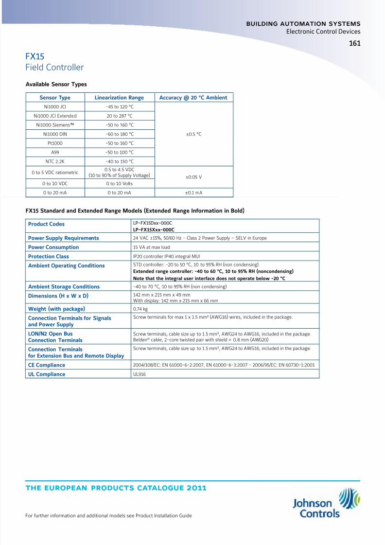
8/6/2019 Publ-6576 Prod Cat 11
http://slidepdf.com/reader/full/publ-6576-prod-cat-11 169/298
the european products catalogue 2011
For further information and additional models see Product Installation Guide
161
building automation systems
Electronic Control Devices
Available Sensor Types
Sensor Type Linearization Range Accuracy @ 20 °C Ambient
Ni1000 JCI -45 to 120 °C
±0.5 °C
Ni1000 JCI Extended 20 to 287 °C
Ni1000 Siemens™ -50 to 160 °C
Ni1000 DIN -60 to 180 °C
Pt1000 -50 to 160 °C
A99 -50 to 100 °C
NTC 2.2K -40 to 150 °C
0 to 5 VDC ratiometric0.5 to 4.5 VDC
(10 to 90% of Supply Voltage) ±0.05 V
0 to 10 VDC 0 to 10 Volts
0 to 20 mA 0 to 20 mA ±0.1 mA
FX15 Standard and Extended Range Models (Extended Range Information in Bold)
Product Codes LP-FX15Dxx-000C
LP-FX15Xxx-000C
Power Supply Requirements 24 VAC ±15%, 50/60 Hz - Class 2 Power Supply – SELV in Europe
Power Consumption 15 VA at max load
Protection Class IP20 controller IP40 integral MUI
Ambient Operating Conditions STD controller: -20 to 50 °C, 10 to 95% RH (non condensing)
Extended range controller: -40 to 60 °C, 10 to 95% RH (noncondensing)
Note that the integral user interface does not operate below -20 °C
Ambient Storage Conditions -40 to 70 °C, 10 to 95% RH (non condensing)
Dimensions (H x W x D) 142 mm x 215 mm x 49 mmWith display: 142 mm x 215 mm x 66 mm
Weight (with package) 0.74 kg
Connection Terminals for Signalsand Power Supply
Screw terminals for max 1 x 1.5 mm² (AWG16) wires, included in the package.
LON/N2 Open BusConnection Terminals
Screw terminals, cable size up to 1.5 mm², AWG24 to AWG16, included in the package.Belden® cable, 2-core twisted pair with shield > 0.8 mm (AWG20)
Connection Terminalsfor Extension Bus and Remote Display
Screw terminals, cable size up to 1.5 mm², AWG24 to AWG16, included in the package.
CE Compliance 2004/108/EC: EN 61000-6-2:2007, EN 61000-6-3:2007 - 2006/95/EC: EN 60730-1:2001
UL Compliance UL916
FX15Field Controller

8/6/2019 Publ-6576 Prod Cat 11
http://slidepdf.com/reader/full/publ-6576-prod-cat-11 170/298
the european products catalogue 2011
For further information and additional models see Product Installation Guide
building automation systems
162
Electronic Control Devices
The FX15 Universal Field Controller is a high performance fieldcontroller in the Facility Explorer system specifically designed forcommercial Heating, Ventilating, and Air Conditioning (HVAC) andrefrigeration applications such as chillers and rooftops, indoorpackaged air conditioning units, Air Handling Units (AHUs), and closecontrol units.
The FX15 Universal has 26 physical inputs and outputs and supports awide range of temperature sensors and actuating devices.Up to 64 additional physical inputs and outputs may be achieved byadding the XT/XP expansion modules on the Local N2 Open bus.
The FX15 is fully programmable or configurable, using the
FX Tools software package, for a wide range of commercial HVACand refrigeration applications. The FX15 controller can be fitted withan optional communication card for integration into an N2 Open orLonWorks
® compatible Building Automation System.
The FX15 also includes an onboard Real-Time Clock to support thestart-stop scheduling of equipment and real-time based controlsequences.
Features z Modular communication card options
z On board real-time clock
z Freely programmable or configurable using FX Tools software package
z
Software selectable analog inputs z User interfaces, integral or remote
z Galvanic isolation between power supply, I/O channels and CPU
179
4465
215
122 142
66
49
35
Dimensions in mm
Ordering Codes Description
LP-FX15D00-000C 6 AIs, 8 DIs, 4 AOs, 8 DOs: 3 Relays + 5 Triacs.
LP-FX15D01-000C 6 AIs, 8 DIs, 4 AOs, 8 DOs: 3 Relays + 5 Triacs, N2 Open Card.
LP-FX15D02-000C 6 AIs, 8 DIs, 4 AOs, 8 DOs: 3 Relays + 5 Triacs, LON® Card.
LP-FX15D50-000C 6 AIs, 8 DIs, 4 AOs, 8 DOs: 3 Relays + 5 Triacs, integral MUI display.
LP-FX15D51-000C 6 AIs, 8 DIs, 4 AOs, 8 DOs: 3 Relays + 5 Triacs, N2 Open Card, integral MUI.
LP-FX15D52-000C 6 AIs, 8 DIs, 4 AOs, 8 DOs: 3 Relays + 5 Triacs, LON® Card, integral MUI.
Communications Cards
Ordering Codes Description
LP-NET151-000C N2 Open Communication Card
LP-NET152-000C LonWorks® Communication Card
User Interface Displays
Ordering Codes Description
LP-DIS60P20-0C Medium User Interface, (4 x 26 character) LCD backlit display, panel mount version.
LP-DIS60P21-0C Medium User Interface, (4 x 26 character) LCD backlit display, wall mount isolated version.
Facility Explorer Controllers Platform
FX15
Universal Field Controller
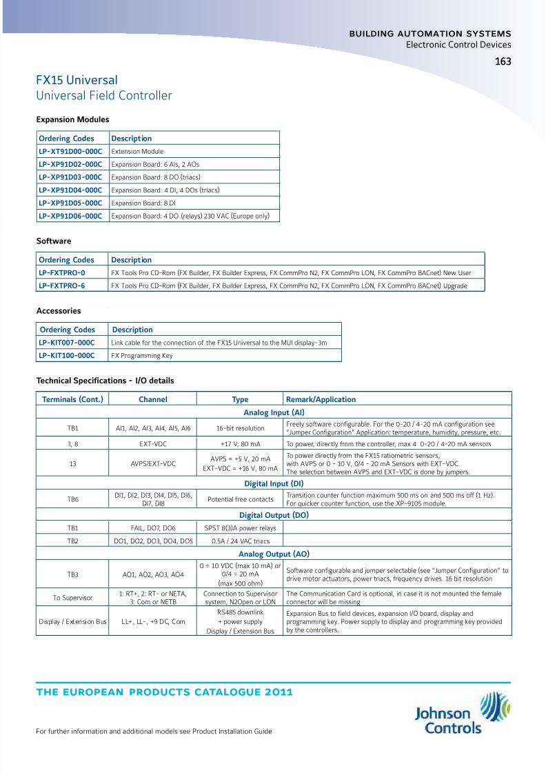
8/6/2019 Publ-6576 Prod Cat 11
http://slidepdf.com/reader/full/publ-6576-prod-cat-11 171/298
the european products catalogue 2011
For further information and additional models see Product Installation Guide
163
building automation systems
Electronic Control Devices
Expansion Modules
Ordering Codes Description
LP-XT91D00-000C Extension Module
LP-XP91D02-000C Expansion Board: 6 AIs, 2 AOs
LP-XP91D03-000C Expansion Board: 8 DO (triacs)
LP-XP91D04-000C Expansion Board: 4 DI, 4 DOs (triacs)
LP-XP91D05-000C Expansion Board: 8 DI
LP-XP91D06-000C Expansion Board: 4 DO (relays) 230 VAC (Europe only)
Accessories
Ordering Codes Description
LP-KIT007-000C Link cable for the connection of the FX15 Universal to the MUI display-3m
LP-KIT100-000C FX Programming Key
Technical Specifications - I/O details
Terminals (Cont.) Channel Type Remark/Application
Analog Input (AI)
TB1 AI1, AI2, AI3, AI4, AI5, AI6 16-bit resolutionFreely software configurable. For the 0-20 / 4-20 mA configuration see“Jumper Configuration” Application: temperature, humidity, pressure, etc.
3, 8 EXT-VDC +17 V, 80 mA To power, directly from the controller, max 4 0-20 / 4-20 mA sensors
13 AVPS/EXT-VDCAVPS = +5 V, 20 mA
EXT-VDC = +16 V, 80 mA
To power directly from the FX15 ratiometric sensors,with AVPS or 0 - 10 V, 0/4 - 20 mA Sensors with EXT-VDC.The selection between AVPS and EXT-VDC is done by jumpers.
Digital Input (DI)
TB6DI1, DI2, DI3, DI4, DI5, DI6,
DI7, DI8Potential free contacts
Transition counter function maximum 500 ms on and 500 ms off (1 Hz).For quicker counter function, use the XP-9105 module.
Digital Output (DO)
TB1 FAIL, DO7, DO6 SPST 8(3)A power relays
TB2 DO1, DO2, DO3, DO4, DO5 0.5A / 24 VAC triacsAnalog Output (AO)
TB3 AO1, AO2, AO3, AO40 ÷ 10 VDC (max 10 mA) or
0/4 ÷ 20 mA
(max 500 ohm)
Software configurable and jumper selectable (see “Jumper Configuration” todrive motor actuators, power triacs, frequency drives. 16 bit resolution
To Supervisor1: RT+, 2: RT- or NETA,
3: Com or NETBConnection to Supervisorsystem, N2Open or LON
The Communication Card is optional, in case it is not mounted the femaleconnector will be missing
Display / Extension Bus LL+, LL-, +9 DC, Com
RS485 downlink
+ power supply
Display / Extension Bus
Expansion Bus to field devices, expansion I/O board, display andprogramming key. Power supply to display and programming key providedby the controllers.
Software
Ordering Codes Description
LP-FXTPRO-0 FX Tools Pro CD-Rom (FX Builder, FX Builder Express, FX CommPro N2, FX CommPro LON, FX CommPro BACnet) New User
LP-FXTPRO-6 FX Tools Pro CD-Rom (FX Builder, FX Builder Express, FX CommPro N2, FX CommPro LON, FX CommPro BACnet) Upgrade
FX15 UniversalUniversal Field Controller
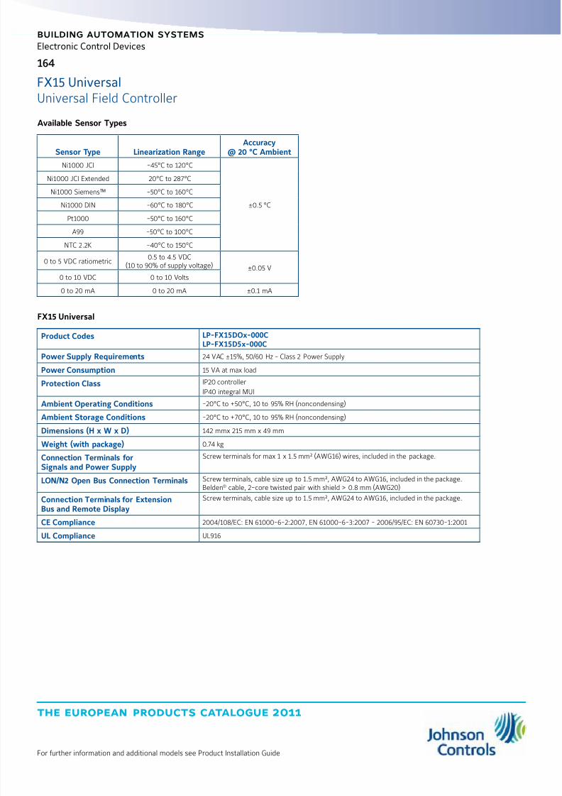
8/6/2019 Publ-6576 Prod Cat 11
http://slidepdf.com/reader/full/publ-6576-prod-cat-11 172/298
the european products catalogue 2011
For further information and additional models see Product Installation Guide
164
building automation systems
Electronic Control Devices
Available Sensor Types
Sensor Type Linearization RangeAccuracy
@ 20 °C Ambient
Ni1000 JCI -45°C to 120°C
±0.5 °C
Ni1000 JCI Extended 20°C to 287°C
Ni1000 Siemens™ -50°C to 160°C
Ni1000 DIN -60°C to 180°C
Pt1000 -50°C to 160°C
A99 -50°C to 100°C
NTC 2.2K -40°C to 150°C
0 to 5 VDC ratiometric0.5 to 4.5 VDC
(10 to 90% of supply voltage) ±0.05 V
0 to 10 VDC 0 to 10 Volts0 to 20 mA 0 to 20 mA ±0.1 mA
FX15 Universal
Product Codes LP-FX15DOx-000CLP-FX15D5x-000C
Power Supply Requirements 24 VAC ±15%, 50/60 Hz - Class 2 Power Supply
Power Consumption 15 VA at max load
Protection Class IP20 controller
IP40 integral MUI
Ambient Operating Conditions -20°C to +50°C, 10 to 95% RH (noncondensing)
Ambient Storage Conditions -20°C to +70°C, 10 to 95% RH (noncondensing)Dimensions (H x W x D) 142 mmx 215 mm x 49 mm
Weight (with package) 0.74 kg
Connection Terminals forSignals and Power Supply
Screw terminals for max 1 x 1.5 mm² (AWG16) wires, included in the package.
LON/N2 Open Bus Connection Terminals Screw terminals, cable size up to 1.5 mm², AWG24 to AWG16, included in the package.Belden® cable, 2-core twisted pair with shield > 0.8 mm (AWG20)
Connection Terminals for ExtensionBus and Remote Display
Screw terminals, cable size up to 1.5 mm², AWG24 to AWG16, included in the package.
CE Compliance 2004/108/EC: EN 61000-6-2:2007, EN 61000-6-3:2007 - 2006/95/EC: EN 60730-1:2001
UL Compliance UL916
FX15 UniversalUniversal Field Controller

8/6/2019 Publ-6576 Prod Cat 11
http://slidepdf.com/reader/full/publ-6576-prod-cat-11 173/298
the european products catalogue 2011
For further information and additional models see Product Installation Guide
165
building automation systems
165
Electronic Control Devices
179
4465
215
122 142
66
49
35
Dimensions in mm
The FX16 Master Controller is a high performance field controllerin the Facility Explorer system designed for commercial Heating,Ventilating, Air Conditioning, and Refrigeration (HVACR) applicationssuch as chillers, rooftops, packaged air conditioning units, Air HandlingUnits (AHUs) and close control units. The FX16 has 27 physical inputsand outputs and supports a wide range of temperature sensors andactuating devices. Up to 64 additional physical inputs and outputs maybe achieved by adding XT/XP expansion modules.
The FX16 can manage a distributed control application with up to 16 FXslave controllers (FX05 Advanced, FX06, FX07, FX14, FX15).Parameters in the distributed control application can be displayed and
modified from the optional user interfaces.The FX16 also features communications services to transmit eventnotification messages via Short Messaging Service (SMS) or by e-mail.With its onboard Web server, you can browse and make adjustmentsto parameters of the application from a remote location.
The FX16 Master Controller is fully configurable or programmable,using the FX Tools software package, for a wide range of commercialHVAC and refrigeration applications. The FX16 Master Controller isavailable with an optional serial communication card for integrationinto an N2 Open, LonWorks
® or BACnet compatible Building AutomationSystem (BAS).
Features
z Distributed control application z Embedded Web server
z Communication services
z Modular communication card options
z Freely programmable or configurable using FX Tools software package
z Onboard trend and event logging
z Software selectable analog inputs
z Optional integral or remote User Interfaces (UI)
Standard Temperature Range Controllers
Ordering Codes Description
LP-FX16D00-000C 6 AIs, 8 DIs, 4 AOs, 9 DOs: 9 relays, no Communication Card
LP-FX16D01-000C 6 AIs, 8 DIs, 4 AOs, 9 DOs: 9 relays, N2 Open Communication Card
LP-FX16D02-000C 6 AIs, 8 DIs, 4 AOs, 9 DOs: 9 relays, LON Communication Card
LP-FX16D03-000C 6 AIs, 8 DIs, 4 AOs, 9 DOs: 9 relays, RS-232 Communication Card
LP-FX16D10-000C 6 AIs, 8 DIs, 4 AOs, 9 DOs: 4 relays, 5 triacs, no Communication Card
LP-FX16D11-000C 6 AIs, 8 DIs, 4 AOs, 9 DOs: 4 relays, 5 triacs, N2 Open Communication Card
LP-FX16D12-000C 6 AIs, 8 DIs, 4 AOs, 9 DOs: 4 relays, 5 triacs, LON Communication Card
LP-FX16D13-000C 6 AIs, 8 DIs, 4 AOs, 9 DOs: 4 relays, 5 triacs, RS-232 Communication Card
Facility Explorer Controllers Platform
FX16
Master Controller
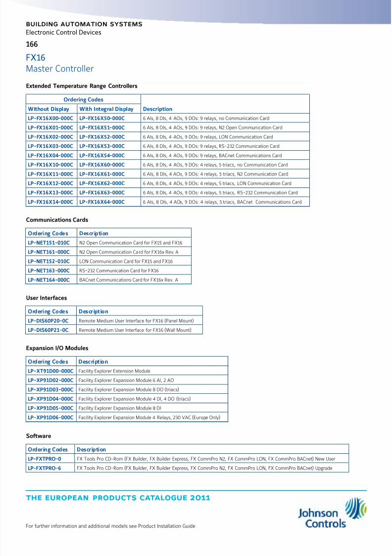
8/6/2019 Publ-6576 Prod Cat 11
http://slidepdf.com/reader/full/publ-6576-prod-cat-11 174/298
the european products catalogue 2011
For further information and additional models see Product Installation Guide
166
building automation systems
Electronic Control Devices
Communications Cards
Ordering Codes Description
LP-NET151-010C N2 Open Communication Card for FX15 and FX16
LP-NET161-000C N2 Open Communication Card for FX16x Rev. A
LP-NET152-010C LON Communication Card for FX15 and FX16
LP-NET163-000C RS-232 Communication Card for FX16
LP-NET164-000C BACnet Communications Card for FX16x Rev. A
User Interfaces
Ordering Codes Description
LP-DIS60P20-0C Remote Medium User Interface for FX16 (Panel Mount)
LP-DIS60P21-0C Remote Medium User Interface for FX16 (Wall Mount)
Expansion I/O Modules
Ordering Codes Description
LP-XT91D00-000C Facility Explorer Extension Module
LP-XP91D02-000C Facility Explorer Expansion Module 6 AI, 2 AO
LP-XP91D03-000C Facility Explorer Expansion Module 8 DO (triacs)
LP-XP91D04-000C Facility Explorer Expansion Module 4 DI, 4 DO (triacs)
LP-XP91D05-000C Facility Explorer Expansion Module 8 DI
LP-XP91D06-000C Facility Explorer Expansion Module 4 Relays, 230 VAC (Europe Only)
Software
Ordering Codes Description
LP-FXTPRO-0 FX Tools Pro CD-Rom (FX Builder, FX Builder Express, FX CommPro N2, FX CommPro LON, FX CommPro BACnet) New User
LP-FXTPRO-6 FX Tools Pro CD-Rom (FX Builder, FX Builder Express, FX CommPro N2, FX CommPro LON, FX CommPro BACnet) Upgrade
Extended Temperature Range Controllers
Ordering Codes
DescriptionWithout Display With Integral Display
LP-FX16X00-000C LP-FX16X50-000C 6 AIs, 8 DIs, 4 AOs, 9 DOs: 9 relays, no Communication Card
LP-FX16X01-000C LP-FX16X51-000C 6 AIs, 8 DIs, 4 AOs, 9 DOs: 9 relays, N2 Open Communication Card
LP-FX16X02-000C LP-FX16X52-000C 6 AIs, 8 DIs, 4 AOs, 9 DOs: 9 relays, LON Communication Card
LP-FX16X03-000C LP-FX16X53-000C 6 AIs, 8 DIs, 4 AOs, 9 DOs: 9 relays, RS-232 Communication Card
LP-FX16X04-000C LP-FX16X54-000C 6 AIs, 8 DIs, 4 AOs, 9 DOs: 9 relays, BACnet Communications Card
LP-FX16X10-000C LP-FX16X60-000C 6 AIs, 8 DIs, 4 AOs, 9 DOs: 4 relays, 5 triacs, no Communication Card
LP-FX16X11-000C LP-FX16X61-000C 6 AIs, 8 DIs, 4 AOs, 9 DOs: 4 relays, 5 triacs, N2 Communication Card
LP-FX16X12-000C LP-FX16X62-000C 6 AIs, 8 DIs, 4 AOs, 9 DOs: 4 relays, 5 triacs, LON Communication Card
LP-FX16X13-000C LP-FX16X63-000C 6 AIs, 8 DIs, 4 AOs, 9 DOs: 4 relays, 5 triacs, RS-232 Communication CardLP-FX16X14-000C LP-FX16X64-000C 6 AIs, 8 DIs, 4 AOs, 9 DOs: 4 relays, 5 triacs, BACnet Communications Card
FX16Master Controller

8/6/2019 Publ-6576 Prod Cat 11
http://slidepdf.com/reader/full/publ-6576-prod-cat-11 175/298

8/6/2019 Publ-6576 Prod Cat 11
http://slidepdf.com/reader/full/publ-6576-prod-cat-11 176/298
the european products catalogue 2011
For further information and additional models see Product Installation Guide
168
building automation systems
Electronic Control Devices
Available Sensor Types
Sensor Type Linearization RangeAccuracy
@ 20 °C Ambient
Ni1000 JCI -45 °C to 120°C
±0.5 °C
Ni1000 JCI Extended 20°C to 287°C
Ni1000 Siemens™ -50°C to 160°C
Ni1000 DIN -60°C to 180°C
Pt1000 -50°C to 160°C
A99 -50°C to 100°C
NTC 2.2K -40°Cto 150°C
0 to 5 VDC ratiometric0.5 to 4.5 VDC
(10 to 90% of supply voltage) ±0.05 V
0 to 10 VDC 0 to 10 Volts0 to 20 mA 0 to 20 mA ±0.1 mA
FX16 Standard and Extended Range Models (Extended Range Information in Bold)
Product Codes LP-FX16Dxx-000C
LP-FX16Xxx-000C
Power Supply Requirements 24 VAC ±15%, 50/60 Hz - Class 2 Power Supply – SELV in Europe
Power Consumption 15 VA at max load
Internal Fuse 2 A, 250 V
Protection Class IP20
Ambient Operating Conditions STD controller: -20°C to +50°C, 10 to 95% RH (noncondensing)
Extended range controller: -40°C to +60°C, 10 to 95% RH (noncondensing)Note that integral user interface does not operate below -20 °C
Ambient Storage Conditions -20°C to +70°C, 10 to 95% RH (noncondensing)
Dimensions (H x W x D) 142 mm x 215 mm x 49 mmWith display: 142 mm x 215 mm x 66 mm
Weight (with package) 0.74 kg
Connection Terminals for Signalsand Power Supply
Screw terminals for max 1 x 1.5 mm² (AWG16) wires, included in the package.
LON / N2 Open / BACnetBus Connection Terminals
Screw terminals, cable size up to 1.5 mm², AWG24 to AWG16, included in the package.
Belden® cable,2-core twisted pair with shield
Connection Terminals for Extension Busand Remote Display Screw terminals, cable size up to 1.5 mm², AWG24 to AWG16, included in the package.
CE Compliance 2004/108/EC: EN 61000-6-2:2007, EN 61000-6-3:2007 - 2006/95/EC: EN 60730-1:2001
UL Compliance UL916
FX16Master Controller
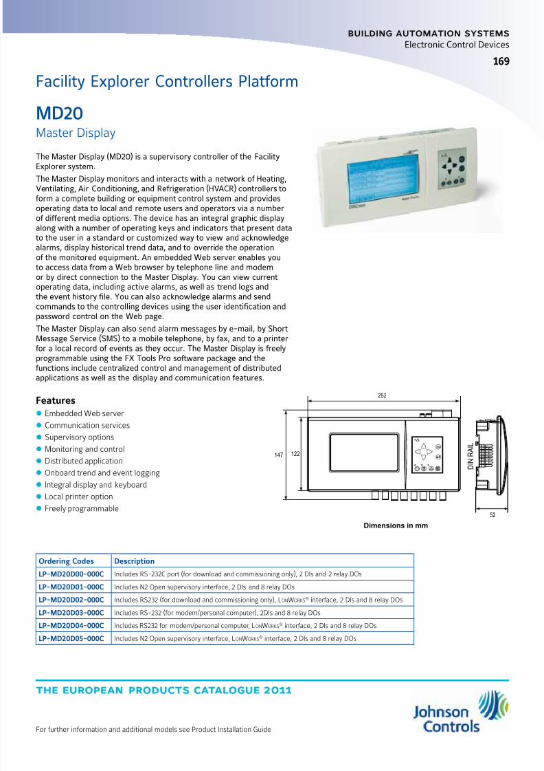
8/6/2019 Publ-6576 Prod Cat 11
http://slidepdf.com/reader/full/publ-6576-prod-cat-11 177/298
the european products catalogue 2011
For further information and additional models see Product Installation Guide
169
building automation systems
169
Electronic Control Devices
52
ESC
D I N R
A I L
122147
252
Dimensions in mm
The Master Display (MD20) is a supervisory controller of the FacilityExplorer system.
The Master Display monitors and interacts with a network of Heating,Ventilating, Air Conditioning, and Refrigeration (HVACR) controllers toform a complete building or equipment control system and providesoperating data to local and remote users and operators via a numberof different media options. The device has an integral graphic displayalong with a number of operating keys and indicators that present datato the user in a standard or customized way to view and acknowledgealarms, display historical trend data, and to override the operationof the monitored equipment. An embedded Web server enables you
to access data from a Web browser by telephone line and modemor by direct connection to the Master Display. You can view currentoperating data, including active alarms, as well as trend logs andthe event history file. You can also acknowledge alarms and sendcommands to the controlling devices using the user identification andpassword control on the Web page.
The Master Display can also send alarm messages by e-mail, by ShortMessage Service (SMS) to a mobile telephone, by fax, and to a printerfor a local record of events as they occur. The Master Display is freelyprogrammable using the FX Tools Pro software package and thefunctions include centralized control and management of distributedapplications as well as the display and communication features.
Features z Embedded Web server
z Communication services
z Supervisory options
z Monitoring and control
z Distributed application
z Onboard trend and event logging
z Integral display and keyboard
z Local printer option
z Freely programmable
Ordering Codes Description
LP-MD20D00-000C Includes RS-232C port (for download and commissioning only), 2 DIs and 2 relay DOs
LP-MD20D01-000C Includes N2 Open supervisory interface, 2 DIs and 8 relay DOs
LP-MD20D02-000C Includes RS232 (for download and commissioning only), LonWorks® interface, 2 DIs and 8 relay DOs
LP-MD20D03-000C Includes RS-232 (for modem/personal computer), 2DIs and 8 relay DOs
LP-MD20D04-000C Includes RS232 for modem/personal computer, LonWorks® interface, 2 DIs and 8 relay DOs
LP-MD20D05-000C Includes N2 Open supervisory interface, LonWorks® interface, 2 DIs and 8 relay DOs
Facility Explorer Controllers Platform
MD20
Master Display
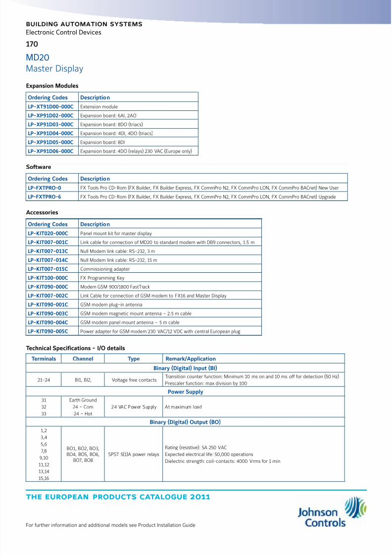
8/6/2019 Publ-6576 Prod Cat 11
http://slidepdf.com/reader/full/publ-6576-prod-cat-11 178/298
the european products catalogue 2011
For further information and additional models see Product Installation Guide
170
building automation systems
Electronic Control Devices
Accessories
Ordering Codes Description
LP-KIT020-000C Panel mount kit for master display
LP-KIT007-001C Link cable for connection of MD20 to standard modem with DB9 connectors, 1.5 m
LP-KIT007-013C Null Modem link cable: RS-232, 3 m
LP-KIT007-014C Null Modem link cable: RS-232, 15 m
LP-KIT007-015C Commissioning adapter
LP-KIT100-000C FX Programming Key
LP-KIT090-000C Modem GSM 900/1800 FastTrack
LP-KIT007-002C Link Cable for connection of GSM modem to FX16 and Master Display
LP-KIT090-001C GSM modem plug-in antenna
LP-KIT090-003C GSM modem magnetic mount antenna – 2.5 m cable
LP-KIT090-004C GSM modem panel mount antenna – 5 m cable
LP-KIT090-005C Power adapter for GSM modem 230 VAC/12 VDC with central European plug
Technical Specifications - I/O details
Terminals Channel Type Remark/Application
Binary (Digital) Input (BI)
21-24 BI1, BI2, Voltage free contactsTransition counter function: Minimum 10 ms on and 10 ms off for detection (50 Hz)
Prescaler function: max division by 100
Power Supply
31
32
33
Earth Ground
24 ~ Com
24 ~ Hot
24 VAC Power Supply At maximum load
Binary (Digital) Output (BO)
1,2
3,4
5,6
7,8
9,10
11,12
13,14
15,16
BO1, BO2, BO3,BO4, BO5, BO6,
BO7, BO8SPST 5(1)A power relays
Rating (resistive): 5A 250 VAC
Expected electrical life: 50,000 operations
Dielectric strength: coil-contacts: 4000 Vrms for 1 min
Software
Ordering Codes Description
LP-FXTPRO-0 FX Tools Pro CD-Rom (FX Builder, FX Builder Express, FX CommPro N2, FX CommPro LON, FX CommPro BACnet) New User
LP-FXTPRO-6 FX Tools Pro CD-Rom (FX Builder, FX Builder Express, FX CommPro N2, FX CommPro LON, FX CommPro BACnet) Upgrade
Expansion Modules
Ordering Codes DescriptionLP-XT91D00-000C Extension module
LP-XP91D02-000C Expansion board: 6AI, 2AO
LP-XP91D03-000C Expansion board: 8DO (triacs)
LP-XP91D04-000C Expansion board: 4DI, 4DO (triacs)
LP-XP91D05-000C Expansion board: 8DI
LP-XP91D06-000C Expansion board: 4DO (relays) 230 VAC (Europe only)
MD20Master Display

8/6/2019 Publ-6576 Prod Cat 11
http://slidepdf.com/reader/full/publ-6576-prod-cat-11 179/298
the european products catalogue 2011
For further information and additional models see Product Installation Guide
171
building automation systems
Electronic Control Devices
Technical Specifications
Product MD20 Master Display
Power Supply 24 VAC ±15% 50/60 Hz – Safety extra low voltage (SELV)
Class 2 in North America
Power Consumption 15 VA maximum
Enclosure Protection ClassEnclosure Material
Front panel mounted: IP54
Rear of panel: IP30 - IEC529 Self-extinguishing to UL94 5VB
Ambient Operating Conditions -20 to +50 °C,10 to 95% RH (non condensing)
Ambient Storage Conditions -20 to +70 °C ,10 to 95% RH (non condensing)
Dimensions (H x W x D) 122 mm x 252 mm x 52 mm
Weight (in delivery package) 1 kg
Display Screen Resolution 240 x 128 Pixels
Supervisory Port RS-485 N2 Open Protocol at 9600 BaudCommunications Port RS-232C PPP Protocol at 9600 Baud for GSM Modem
Printer Port Comm. Speed 9600 Baud
LonWorks® Interface FTT (Free Topology Transceiver) at 78 Kbps. MIP interface between Neuron® chip and controller microprocessor
Local Link Bus RS-485 N2 Open/N2 System91 Protocol at 9600 Baud
I/O Expansion Bus RS-485 N2 XT Bus Protocol at 9600 Baud
Output Relay Contacts SPST 250 VAC 5(1)A (Minimum closure time 100 ms)
Input Binary Contacts Voltage-free, 1k ohm maximum
Power Supply and I/O Terminals Screw terminal connectors for max 1.5 mm2 (AWG 16) wire
Communication Terminals RS-485 (N2) and LonWorks (FTT) – screw terminals for max 0.8 mm (AWG20) wire
CE Compliance 2004/108/EC: EN 61000-6-2:2007, EN 61000-6-3:2007 - 2006/95/EC: EN 60730-1:2001
UL Compliance UL916
MD20Master Display

8/6/2019 Publ-6576 Prod Cat 11
http://slidepdf.com/reader/full/publ-6576-prod-cat-11 180/298
the european products catalogue 2011
For further information and additional models see Product Installation Guide
building automation systems
172
Electronic Control Devices
The Medium User Interface, is a local / remote display for the FX06,FX07, FX14, FX15, FX15 Universal Field Controller and FX16 MasterController.
It is designed for the end user or for the maintenance people whoneeds a clear and straightforward way to monitor and adjust data.
Information are presented in textual format in the 4 x 26 backlit LCDdisplay. The display is IP54, it has an extended temperature range:-20 °C to 50 °C and can be hand held or permanently mounted on apanel or on a wall.
Features z Menu operations
z Alarm summary page
z Password access
z Software customisation
z Universal power supply
179
4475 35
32
Dimensions in mm
Ordering Codes PowerSupply Protection Class Description
LP-DIS60P20-000C
9 - 48 VDC
24 VAC ±10%
Hand-held and Wall mount applications IP30
Panel mount applications IP54
MUI Display, Panel mount non-isolated version
LP-DIS60P21-000C MUI Display, Wall or panel mount isolated version
LP-KIT007-000C3 m connection cable for FX07, FX14, FX15, FX15 Universaland FX16 Master Controller
Facility Explorer Controllers Platform
MUI
Medium User Interface

8/6/2019 Publ-6576 Prod Cat 11
http://slidepdf.com/reader/full/publ-6576-prod-cat-11 181/298

8/6/2019 Publ-6576 Prod Cat 11
http://slidepdf.com/reader/full/publ-6576-prod-cat-11 182/298
the european products catalogue 2011
For further information and additional models see Product Installation Guide
174
building automation systems
Electronic Control Devices
XM14 Modules
Ordering Codes Description
24 VAC Power Supply
LP-XM14X01-000C FX I/O Module with 6 UIs, 12 BIs, 4 AOs, 9 Relay Dos.
LP-XM14X11-000C FX I/O Module with 6 UIs, 12 BIs, 4 AOs, 4 Triac DOs.
LP-XM14X51-000C FX I/O Module with 6 UIs, 12 BIs, 4 AOs, 9 Relay DOs. Manual Overrides for 3 AOs and 7 Relay DOs
LP-XM14X61-000C FX I/O Module with 6 UIs, 12 BIs, 4 AOs, 4 Triac DOs, 5 Relay DOs. Manual Overrides for 3 AOs, 2 Triac DOs, and 5 Relay DOs
90 to 240 VAC Power Supply (Not Available in North America)
LP-XM14B01-000C FX I/O Module with 6 UIs, 12 BIs, 4 AOs, 9 Relay DOs.LP-XM14B11-000C FX I/O Module with 6 UIs, 12 BIs, 4 AOs, 4 Triac DOs.
LP-XM14B51-000C FX I/O Module with 6 UIs, 12 BIs, 4 AOs, 9 Relay DOs. Manual Overrides for 3 AOs and 7 Relay DOs
LP-XM14B61-000C FX I/O Module with 6 UIs, 12 BIs, 4 AOs, 4 Triac DOs, 5 Relay DOs. Manual Overrides for 3 AOs, 2 Triac DOs, and 5 Relay DOs
Accessories
Ordering Codes Description
LP-KIT007-200C Screw connectors kit for XM07 (replacement part – kit included in each XM07 module)
LP-KIT014-200C Screw connectors kit for XM14 (replacement part – kit included in each XM14 module)
LP-NET071-000C Local link (N2 Open RS-485) communication card for XM07 (replacement part – card included in each XM07 module)
LP-NET161-000C Local link (N2 Open RS-485) communication card for XM14 (replacement part – card included in each XM14 module)
XM07 Modules
Ordering Codes Description
24 VAC Power Supply
LP-XM07X01-000C FX I/O Module with 5 UIs, 4 BIs, 3 AOs, 6 Relay DOs
LP-XM07X11-000C FX I/O Module with 5 UIs, 4 BIs, 3 AOs, 2 Triac DOs, 4 Relay DOs.
LP-XM07X51-000C FX I/O Module with 5 UIs, 4 BIs, 3 AOs, 6 Relay DOs. Manual Overrides for 2 AOs and 4 Relay DOs.
LP-XM07X61-000C FX I/O Module with 5 UIs, 4 BIs, 3 AOs, 2 Triac DOs, 4 Relay DOs. Manual Overrides for 2 AOs, 2 Triac DOs, and 2 Relay DOs.
90 to 240 VAC Power Supply (Not Available in North America)
LP-XM07B01-000C FX I/O Module with 5 UIs, 4 BIs, 3 AOs, 6 Relay DOs.
LP-XM07B11-000C FX I/O Module with 5 UIs, 4 BIs, 3 AOs, 2 Triac DOs, 4 Relay DOs.
LP-XM07B51-000C FX I/O Module with 5 UIs, 4 BIs, 3 AOs, 6 Relay DOs. Manual Overrides for 2 AOs and 4 Relay DOs.
LP-XM07B61-000C FX I/O Module with 5 UIs, 4 BIs, 3 AOs, 2 Triac DOs, 4 Relay DOs. Manual Overrides for 2 AOs, 2 Triac DOs, and 2 Relay DOs.
XM07 and XM14FX Input/Output (I/O) Modules

8/6/2019 Publ-6576 Prod Cat 11
http://slidepdf.com/reader/full/publ-6576-prod-cat-11 183/298
the european products catalogue 2011
For further information and additional models see Product Installation Guide
175
building automation systems
Electronic Control Devices
Technical Specifications - Universal Inputs (UI) - All Models
Models Channel Type Remark/Application
LP-XM07(All Models) UI1, UI2, UI3, UI4, UI5See
“Universal Input Sensor Types”in table below
Software configurable.Application: temperature, humidity, pressure analog inputsat 16-bit resolution or equipment status binary inputs.Jumper for permanent current shunt path on one inputUI1 on XM07 and UI6 on XM14.
LP-XM14 (All Models) UI1, UI2, UI3, UI4, UI5, UI6
LP-XM07 and LP-XM14(All Models)
+5 VUI Power:
5 VDC +/-10% at 20 mA maxUsed to power active or ratiometric sensors directly from thecontroller
+15 VUI/AO Power:
15 VDC +/-10% at 80 mA maxUsed to power active sensors directly from the controller.(Also used for PWM outputs using 10 mA each.)
Universal Input Sensor Types
Sensor TypesFull Linearization
Range
Accuracy at 20°CModule Circuits Only
(Sensor Accuracy Not Included)
A99 -50 to 100°C
±0.5°CNTC 10k -40 to 150°C
PT1000 Extended -50 to 160°C
Ni1000 (Johnson Controls) -45 to 120°C
Active Voltage 0-10 VDC±0.05 VDC
Active Ratiometric 0.5-4.5 VDC
Active Current 0(4)-20 mA ±0.2 mA
Potential-Free Contact Binary open/close sense Not applicable
Digital (Binary) Input (DI) - All Models
Models Channel Type Indication Remark/Application
LP-XM07(All Models) DI1, DI2, DI3, DI4
Potential-free contactopen/close
Software configurable LED(green or red)
ON for closed or OPEN contact
Equipment status and events
LP-XM14 (All Models) DI1, DI2, DI3, DI4, DI5, DI6,DI7, DI8, DI9, DI10, DI11,
DI12
Transition counter at 50 Hz maxMinimum Time ON: 10 msMinimum Time OFF: 10 ms
XM07 and XM14FX Input/Output (I/O) Modules
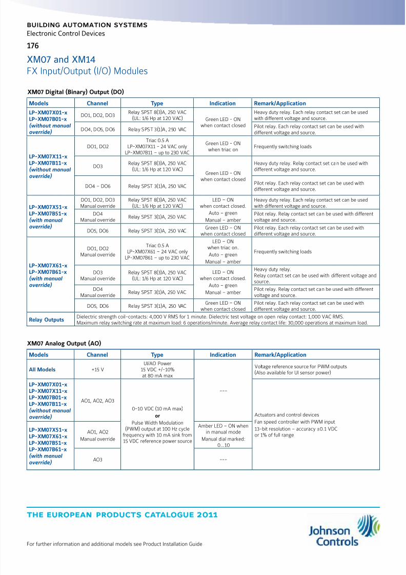
8/6/2019 Publ-6576 Prod Cat 11
http://slidepdf.com/reader/full/publ-6576-prod-cat-11 184/298
the european products catalogue 2011
For further information and additional models see Product Installation Guide
176
building automation systems
Electronic Control Devices
XM07 Analog Output (AO)
Models Channel Type Indication Remark/Application
All Models +15 VUI/AO Power
15 VDC +/-10%at 80 mA max
---
Voltage reference source for PWM outputs(Also available for UI sensor power)
LP-XM07X01-xLP-XM07X11-xLP-XM07B01-x
LP-XM07B11-x(without manual override)
AO1, AO2, AO30-10 VDC (10 mA max)
or
Pulse Width Modulation(PWM) output at 100 Hz cycle
frequency with 10 mA sink from15 VDC reference power source
Actuators and control devices
Fan speed controller with PWM input
13-bit resolution – accuracy ±0.1 VDCor 1% of full range
LP-XM07X51-xLP-XM07X61-xLP-XM07B51-xLP-XM07B61-x(with manual override)
AO1, AO2
Manual override
Amber LED – ON whenin manual mode
Manual dial marked:0...10
AO3 ---
XM07 Digital (Binary) Output (DO)
Models Channel Type Indication Remark/Application
LP-XM07X01-xLP-XM07B01-x(without manual override)
DO1, DO2, DO3Relay SPST 8(3)A, 250 VAC
(UL: 1/6 Hp at 120 VAC) Green LED - ONwhen contact closed
Heavy duty relay. Each relay contact set can be usedwith different voltage and source.
DO4, DO5, DO6 Relay SPST 3(1)A, 250 VACPilot relay. Each relay contact set can be used withdifferent voltage and source.
LP-XM07X11-xLP-XM07B11-x(without manual override)
DO1, DO2Triac 0.5 A
LP-XM07X11 - 24 VAC onlyLP-XM07B11 – up to 230 VAC
Green LED - ONwhen triac on
Frequently switching loads
DO3Relay SPST 8(3)A, 250 VAC
(UL: 1/6 Hp at 120 VAC)Green LED - ON
when contact closed
Heavy duty relay. Relay contact set can be used withdifferent voltage and source.
DO4 – DO6 Relay SPST 3(1)A, 250 VACPilot relay. Each relay contact set can be used withdifferent voltage and source.
LP-XM07X51-xLP-XM07B51-x(with manual override)
DO1, DO2, DO3Manual override Relay SPST 8(3)A, 250 VAC(UL: 1/6 Hp at 120 VAC) LED – ONwhen contact closed.
Auto – green
Manual – amber
Heavy duty relay. Each relay contact set can be usedwith different voltage and source.
DO4Manual override
Relay SPST 3(1)A, 250 VACPilot relay. Relay contact set can be used with differentvoltage and source.
DO5, DO6 Relay SPST 3(1)A, 250 VACGreen LED – ON
when contact closedPilot relay. Each relay contact set can be used withdifferent voltage and source.
LP-XM07X61-xLP-XM07B61-x(with manual override)
DO1, DO2Manual override
Triac 0.5 ALP-XM07X61 – 24 VAC only
LP-XM07B61 – up to 230 VAC
LED – ONwhen triac on.
Auto – green
Manual – amber
Frequently switching loads
DO3Manual override
Relay SPST 8(3)A, 250 VAC(UL: 1/6 Hp at 120 VAC)
LED – ONwhen contact closed.
Auto – green
Manual – amber
Heavy duty relay.Relay contact set can be used with different voltage andsource.
DO4Manual override
Relay SPST 3(1)A, 250 VACPilot relay. Relay contact set can be used with differentvoltage and source.
DO5, DO6 Relay SPST 3(1)A, 250 VAC Green LED – ONwhen contact closed
Pilot relay. Each relay contact set can be used withdifferent voltage and source.
Relay OutputsDielectric strength coil-contacts: 4,000 V RMS for 1 minute. Dielectric test voltage on open relay contact: 1,000 VAC RMS.Maximum relay switching rate at maximum load: 6 operations/minute. Average relay contact life: 30,000 operations at maximum load.
XM07 and XM14FX Input/Output (I/O) Modules
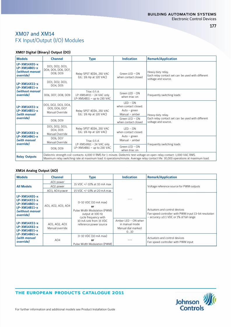
8/6/2019 Publ-6576 Prod Cat 11
http://slidepdf.com/reader/full/publ-6576-prod-cat-11 185/298
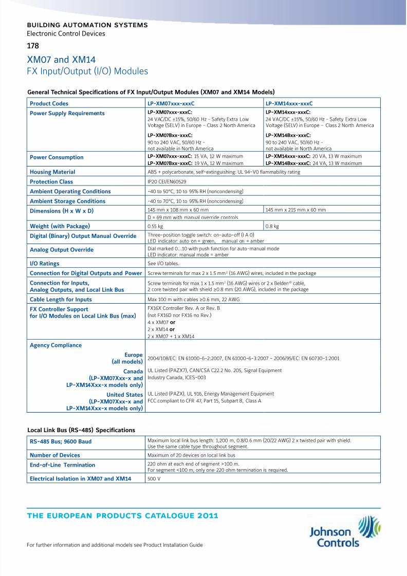
8/6/2019 Publ-6576 Prod Cat 11
http://slidepdf.com/reader/full/publ-6576-prod-cat-11 186/298
the european products catalogue 2011
For further information and additional models see Product Installation Guide
178
building automation systems
Electronic Control Devices
General Technical Specifications of FX Input/Output Modules (XM07 and XM14 Models)
Product Codes LP-XM07xxx-xxxC LP-XM14xxx-xxxC
Power Supply Requirements LP-XM07xxx-xxxC:
24 VAC/DC ±15%, 50/60 Hz - Safety Extra LowVoltage (SELV) in Europe – Class 2 North America
LP-XM07Bxx-xxxC:
90 to 240 VAC, 50/60 Hz -not available in North America
LP-XM14xxx-xxxC:
24 VAC/DC ±15%, 50/60 Hz - Safety Extra LowVoltage (SELV) in Europe – Class 2 North America
LP-XM14Bxx-xxxC:
90 to 240 VAC, 50/60 Hz -not available in North America
Power Consumption LP-XM07xxx-xxxC: 15 VA, 12 W maximum
LP-XM07Bxx-xxxC: 19 VA, 12 W maximum
LP-XM14xxx-xxxC: 20 VA, 13 W maximum
LP-XM14Bxx-xxxC: 24 VA, 13 W maximum
Housing Material ABS + polycarbonate, self-extinguishing: UL 94-V0 flammability rating
Protection Class IP20 CEI/EN60529
Ambient Operating Conditions -40 to 50°C, 10 to 95% RH (noncondensing)
Ambient Storage Conditions -40 to 70°C, 10 to 95% RH (noncondensing)Dimensions (H x W x D) 145 mm x 108 mm x 60 mm 145 mm x 215 mm x 60 mm
D = 69 mm with manual override controls
Weight (with Package) 0.55 kg 0.8 kg
Digital (Binary) Output Manual Override Three-position toggle switch: on-auto-off (I A 0)LED indicator: auto on = green, manual on = amber
Analog Output Override Dial marked 0…10 with push function for auto-manual modeLED indicator: manual mode = amber
I/O Ratings See I/O tables.
Connection for Digital Outputs and Power Screw terminals for max 2 x 1.5 mm2 (16 AWG) wires, included in the package
Connection for Inputs,Analog Outputs, and Local Link Bus
Screw terminals for max 1 x 1.5 mm2 (16 AWG) wires or 2 x Belden® cable,2 core twisted pair with shield ≥0.8 mm (20 AWG), included in the package
Cable Length for Inputs Max 100 m with cables ≥0.6 mm, 22 AWG
FX Controller Supportfor I/O Modules on Local Link Bus (max)
FX16X Controller Rev. A or Rev. B
(not FX16D nor FX16 no Rev.)
4 x XM07 or2 x XM14 or2 x XM07 + 1 x XM14
Agency Compliance
Europe(all models)
2004/108/EC: EN 61000-6-2:2007, EN 61000-6-3:2007 - 2006/95/EC: EN 60730-1:2001
Canada(LP-XM07Xxx-x and
LP-XM14Xxx-x models only)
UL Listed (PAZX7), CAN/CSA C22.2 No. 205, Signal Equipment
Industry Canada, ICES-003
United States
(LP-XM07Xxx-x andLP-XM14Xxx-x models only)
UL Listed (PAZX), UL 916, Energy Management Equipment
FCC compliant to CFR 47, Part 15, Subpart B, Class A
Local Link Bus (RS-485) Specifications
RS-485 Bus; 9600 Baud Maximum local link bus length: 1,200 m, 0.8/0.6 mm (20/22 AWG) 2 x twisted pair with shield.Use the same cable type throughout segment.
Number of Devices Maximum of 20 devices on local link bus
End-of-Line Termination 220 ohm at each end of segment >100 m.For segment <100 m, only one 220 ohm termination is required.
Electrical Isolation in XM07 and XM14 500 V
XM07 and XM14FX Input/Output (I/O) Modules

8/6/2019 Publ-6576 Prod Cat 11
http://slidepdf.com/reader/full/publ-6576-prod-cat-11 187/298

8/6/2019 Publ-6576 Prod Cat 11
http://slidepdf.com/reader/full/publ-6576-prod-cat-11 188/298
the european products catalogue 2011
For further information and additional models see Product Installation Guide
building automation systems
180
Electronic Control Devices
FX Tools Pro is a Windows® based software package for theconfiguration, downloading and commissioning of Heating, Ventilating,Air Conditioning, and Refrigeration (HVACR) applications for the FacilityExplorer field controllers. The FX Tools Pro software package includesFX Builder, FX Builder Express, FX CommPro N2, FX CommPro LON,FX CommPro BACnet and FX Loader. The FX Builder tool provides themenus, navigation trees, and graphic screens for the programmingand configuration of the Facility Explorer controllers. The configurationincludes the definition of the controllers to be connected, the physicalinputs and outputs and data points to be monitored, and the format of the local display screen of the controller.
The Facility Explorer controllers are downloaded and commissionedusing the FX CommPro tool. FX CommPro is available in threeversions: FX CommPro N2, FX CommPro LON and FX CommProBACnet.
FX CommPro enables the monitoring and control of the connectedFacility Explorer controller. Setting parameters, tuning controls, andsaving default parameters for other controller configurations are allfeatures of the FX CommPro for the N2 Open, LonWorks
® and BACnetprotocols.
FX Loader is a specialized utility used to download applications andfirmware updates to Facility Explorer controllers.
Features
z FX device support z Graphical environment
z Application Management
z Reusable macro assemblies
z Offline simulation
z Online commissioning
System Requirements
Operating System Microsoft Windows 2000 (with Service Pack 4 or later)
Microsoft Windows XP (with Service Pack 1 or later)
Hardware Requirements
Processor Intel® Pentium® Processor, 500 MHz or higher
RAM Minimum 512 MB RAM
Hard Disk 60 MB available hard disk storage minimum
Display Display resolution 800 x 600 16-bit (32,768) color minimum
Interface RS232, USB
Other Software Requirements Microsoft Internet Explorer Version 5.0 or later
Ordering Codes Description
LP-FXTPRO-0 FX Tools Pro CD-Rom (FX Builder, FX Builder Express, FX CommPro N2, FX CommPro LON, FX CommPro BACnet) New User
LP-FXTPRO-6 FX Tools Pro CD-Rom (FX Builder, FX Builder Express, FX CommPro N2, FX CommPro LON, FX CommPro BACnet) Upgrade
Facility Explorer Controllers Platform
FX TOOLS PRO

8/6/2019 Publ-6576 Prod Cat 11
http://slidepdf.com/reader/full/publ-6576-prod-cat-11 189/298
the european products catalogue 2011
For further information and additional models see Product Installation Guide
181
building automation systems
181
Electronic Control Devices
The AD-FCC and AD-FCD Fan Coil Unit Controller are LonWorks®
network compatible devices that provide direct digital control of a fancoil unit with heating and/or cooling coils, an electric heater and athree-speed fan.
The controller is designed for field installation or for mounting byoriginal equipment manufacturers (OEMs).
The space comfort set point, occupancy mode and fan speed may beadjusted from a room command module.
The AD-FCC connects to the TM-21x0 series module and the AD-FCDuses the AD-IRM1005 module with a digital LCD display.A LonWorks compatible Room Command Module may also be used
when the controller is integrated into a LonWorks network.The controller complies with the LonMark
® interoperability guidelinesfor sharing data with other network sensors and devices. Operatingdata can be monitored and controlled from a LonWorks compatiblesupervisory system, including the Metasys® NCM Network ControlModule and NAE Network Automation Engine that integrate the fan coilunit controller into a facility-wide management network.
Features z 230 VAC power
z Relay outputs at 230 VAC 3A for direct fan control
z Triac outputs at 230 VAC for heating and cooling valve control
z
Relay output for electric heater control z Temperature setpoint and fan speed override from attractively styledroom command module with option for digital display
z Multiple modes of operation for various occupancy conditions
z Configuration and commissioning using any LonMark compatibleLonWorks network or commissioning tool
z LonWorks peer-to-peer communications network
z LonMark Space Comfort Controller Profile
z LonWorks network connection to Metasys network controller
132
118
7895.2
Ø 3.5
Dimensions in mm
AD-IRM1005
Integrated Room Module
with displayTM-2100
Series Room Module
AD-FCC and AD-FCD
Fan Coil Control Solution
Metasys® Field Controllers LonWorks® Compatible
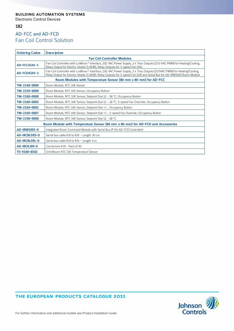
8/6/2019 Publ-6576 Prod Cat 11
http://slidepdf.com/reader/full/publ-6576-prod-cat-11 190/298
the european products catalogue 2011
For further information and additional models see Product Installation Guide
182
building automation systems
Electronic Control Devices
Ordering Codes Description
Fan Coil Controller Modules
AD-FCC4245-1Fan Coil Controller with LonWorks
® Interface, 230 VAC Power Supply, 2 x Triac Outputs (230 VAC PWM) for Heating/Cooling,Relay Output for Electric Heater (1.5KW), Relay Outputs for 3-speed Fan (3A).
AD-FCD4245-1Fan Coil Controller with LonWorks
® Interface, 230 VAC Power Supply, 2 x Triac Outputs (230VAC PWM) for Heating/Cooling,Relay Output for Electric Heater (1.5KW), Relay Outputs for 3-speed Fan (3A) and Serial Bus for AD-IRM1005 Room Module
Room Modules with Temperature Sensor (80 mm x 80 mm) for AD-FCC
TM-2140-0000 Room Module, NTC 10K Sensor
TM-2150-0000 Room Module, NTC 10K Sensor, Occupancy Button
TM-2160-0000 Room Module, NTC 10K Sensor, Setpoint Dial 12 - 28 °C, Occupancy Button
TM-2160-0002 Room Module, NTC 10K Sensor, Setpoint Dial 12 - 28 °C, 3-speed Fan Override, Occupancy Button
TM-2160-0005 Room Module, NTC 10K Sensor, Setpoint Dial +/-, Occupancy Button
TM-2160-0007 Room Module, NTC 10K Sensor, Setpoint Dial +/-, 3-speed Fan Override, Occupancy Button
TM-2190-0000 Room Module, NTC 10K Sensor, Setpoint Dial 12 - 28 °C
Room Module with Temperature Sensor (80 mm x 80 mm) for AD-FCD and Accessories
AD-IRM1005-0 Integrated Room Command Module with Serial Bus I/F (to AD-FCD Controller)
AD-IRCBL99S-0 Serial bus cable RJ9 to RJ9 – Length 30 cm
AD-IRCBL99L-0 Serial bus cable RJ9 to RJ9 – Length 6 m
AD-IRCKJ09-0 Connectors RJ9 - Pack of 50
TE-9100-8502 Unit Mount NTC 10k Temperature Sensor
AD-FCC and AD-FCD
Fan Coil Control Solution
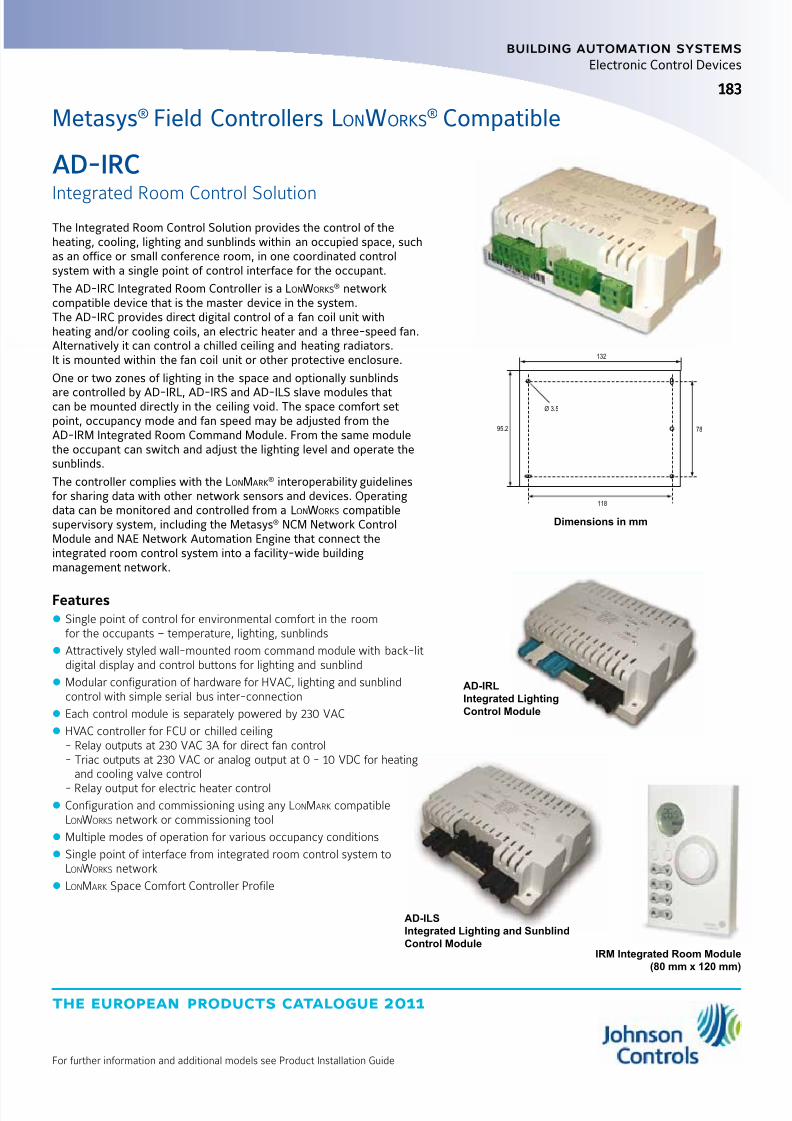
8/6/2019 Publ-6576 Prod Cat 11
http://slidepdf.com/reader/full/publ-6576-prod-cat-11 191/298
the european products catalogue 2011
For further information and additional models see Product Installation Guide
183
building automation systems
183
Electronic Control Devices
The Integrated Room Control Solution provides the control of theheating, cooling, lighting and sunblinds within an occupied space, suchas an office or small conference room, in one coordinated controlsystem with a single point of control interface for the occupant.
The AD-IRC Integrated Room Controller is a LonWorks® network
compatible device that is the master device in the system.The AD-IRC provides direct digital control of a fan coil unit withheating and/or cooling coils, an electric heater and a three-speed fan.Alternatively it can control a chilled ceiling and heating radiators.It is mounted within the fan coil unit or other protective enclosure.
One or two zones of lighting in the space and optionally sunblinds
are controlled by AD-IRL, AD-IRS and AD-ILS slave modules thatcan be mounted directly in the ceiling void. The space comfort setpoint, occupancy mode and fan speed may be adjusted from theAD-IRM Integrated Room Command Module. From the same modulethe occupant can switch and adjust the lighting level and operate thesunblinds.
The controller complies with the LonMark® interoperability guidelines
for sharing data with other network sensors and devices. Operatingdata can be monitored and controlled from a LonWorks compatiblesupervisory system, including the Metasys® NCM Network ControlModule and NAE Network Automation Engine that connect theintegrated room control system into a facility-wide buildingmanagement network.
Features z Single point of control for environmental comfort in the roomfor the occupants – temperature, lighting, sunblinds
z Attractively styled wall-mounted room command module with back-litdigital display and control buttons for lighting and sunblind
z Modular configuration of hardware for HVAC, lighting and sunblindcontrol with simple serial bus inter-connection
z Each control module is separately powered by 230 VAC
z HVAC controller for FCU or chilled ceiling- Relay outputs at 230 VAC 3A for direct fan control- Triac outputs at 230 VAC or analog output at 0 - 10 VDC for heating
and cooling valve control
- Relay output for electric heater control z Configuration and commissioning using any LonMark compatibleLonWorks network or commissioning tool
z Multiple modes of operation for various occupancy conditions
z Single point of interface from integrated room control system toLonWorks network
z LonMark Space Comfort Controller Profile
Dimensions in mm
132
118
7895.2
Ø 3.5
AD-IRC
Integrated Room Control Solution
Metasys® Field Controllers LonWorks® Compatible
AD-ILS
Integrated Lighting and Sunblind
Control ModuleIRM Integrated Room Module
(80 mm x 120 mm)
AD-IRL
Integrated Lighting
Control Module

8/6/2019 Publ-6576 Prod Cat 11
http://slidepdf.com/reader/full/publ-6576-prod-cat-11 192/298
the european products catalogue 2011
For further information and additional models see Product Installation Guide
184
building automation systems
Electronic Control Devices
Ordering Codes Description
Integrated Room Control Solution Components
AD-IRC4205-1IRC HVAC Controller with LonWorks
® Interface and Serial Bus I/F (to IRC Lighting, Sunblind and Room Command Modules),230 VAC Power Supply, 2 x Analog Outputs (0 - 10 V) for Heating/Cooling, Relay Output for Electric Heater (1.5KW),Relay Outputs for 3-speed Fan (3A)
AD-IRC4245-1IRC HVAC Controller with LonWorks
® Interface and Serial Bus I/F (to IRC Lighting, Sunblind and Room Command Modules),230 VAC Power Supply, 4 x Triac Outputs (230 VAC PWM or INC/DEC) for Heating/Cooling, Relay Output for Electric Heater (1.5KW),Relay Outputs for 3-speed Fan (3A)
AD-ILS1035-0IRC Lighting and Sunblind Module with Serial Bus I/F (to HVAC Controller), 230 VAC Power Supply,2 x Lighting On/Off and 1 x Sunblind Outputs (230 VAC)
AD-IRL1025-0 IRC Lighting Module with Serial Bus I/F (to HVAC Controller), 230 VAC Power Supply, 2 x Lighting On/Off Outputs (230 VAC)
AD-IRL2025-0IRC Lighting Module with Serial Bus I/F (to HVAC Controller), 230 VAC Power Supply, 2 x Lighting Outputs (230 VAC)with Dimming Control
AD-IRS1035-0 IRC Sunblind Module with Serial Bus I /F (to HVAC Controller), 230 VAC Power Supply, 3 x Sunblind Outputs (230 VAC)
AD-IRM1005-0
Integrated Room Command Module with Serial Bus I/F (to HVAC Controller)
– HVAC only (80 mm x 80 mm)
AD-IRM1015-0Integrated Room Command Module with Serial Bus I/F (to HVAC Controller)
– 2 Lighting Control Buttons (80 mm x 120 mm)
AD-IRM1025-0Integrated Room Command Module with Serial Bus I/F (to HVAC Controller)
– 2 x Lighting + 1 x Sunblind Control Buttons (80 mm x 120 mm)
AD-IRM1035-0Integrated Room Command Module with Serial Bus I/F (to HVAC Controller)
– 2 Lighting + 2 x Sunblind Control Buttons (80 mm x 120 mm)
Integrated Room Control Solution Accessories
TE-9100-8502 Unit Mount NTC 10k Temperature Sensor
AD-IRL1025CK-0 Connector Kit for AD-IRL1025-0 (Power + 2 x Lighting Circuit)
AD-IRL2025CK-0 Connector Kit for AD-IRL2025-0 (Power + 2 x Lighting/Dimming Circuit)
AD-IRS1035CK-0 Connector Kit for AD-IRS1035-0 (Power + 3 x Sunblind Circuit)
AD-ILS1035CK-0 Connector Kit for AD-ILS1035-0 (Power + 2 x Lighting + Sunblind Circuit)AD-IRCBL911S-0 Serial bus cable RJ9 to RJ11 – Length 30 cm
AD-IRCBL911L-0 Serial bus cable RJ9 to RJ11 – Length 6 m
AD-IRCBL99S-0 Serial bus cable RJ9 to RJ9 – Length 30 cm
AD-IRCBL99L-0 Serial bus cable RJ9 to RJ9 – Length 6 m
AD-IRCKJ09-0 Connectors RJ9 - Pack of 50
AD-IRCKJ11-0 Connectors RJ11 - Pack of 50
AD-IRC
Integrated Room Control Solution

8/6/2019 Publ-6576 Prod Cat 11
http://slidepdf.com/reader/full/publ-6576-prod-cat-11 193/298
the european products catalogue 2011
For further information and additional models see Product Installation Guide
185
building automation systems
185
Electronic Control Devices
The DX-9121 LonWorks® Digital Controller, is the ideal digital control
solution for multiple chiller or boiler plant control applications, forair handling units or for distributed lighting and related electricalequipment control applications. The controller has both the hardwareand software flexibility to adapt to the variety of control requirementsin its targeted applications and can extend its input and output pointcapability by communicating with input/output (I/O) extension moduleson an extension bus. The controller provides monitoring and controlof all connected points at an integral LED display and keyboard orfrom a separate DT-9100 display unit. The DT-9100 display unit, witha text and graphic LCD screen and keypad, provides a standard andcustomized presentation of data according to the application andcustomer requirements. Both the DX-9121 controller and theDT-9100 display unit can be mounted within an electrical enclosure orin a cabinet door, and the DT-9100 display unit can also be mounteddirectly onto the controller within a panel, on a wall or can be usedas a portable device. Additionally, each controller can share data withother DX-9121 controllers on the same N2E bus. When the N2E busis integrated into a Metasys® system, point and control informationis available throughout the network and at all Metasys operatorworkstations.
Features z LonWorks
® network communications (Metasys N2E)
z Dynamic data access capabilities with NCMand Metasys system network
z Full set of control algorithms in software modules
z Graphic configuration tool
z Standalone control
z Real-time clock and time programs
z Trend data storage
z Extension bus for additional I/O points
z Extension modules for a variety of analogand digital I/O combinations
z Model with integral display and control panel
z Text and graphic display unit (DT-9100)
z Extension modules with manual override switches
Model with LED display
and Keyboard in Cabinet Door
Mounting Frame
Black Box Model
on Panel Mounting Base
Ordering Codes Analog InputsBinaryInputs
AnalogOutputs
BinaryOutputs
Panel withLED Display
PowerSupply
CommunicationBus
DX-9121-80048 8 8 6
NO(Black Box) 24 VAC ±10%,
50/60 HzFTT
DX-9121-8454 YES
Jumper Selectable
RTD (1KΩ NI) 0-10 VDC Transmitter 0-20 mA Transmitter (4 max.)
Dry ContactsJumper Selectable
0-10 VDC 0-20 mA (4)
24 VAC Triacsat 0.5 amps
NoteRefer to DX-9200 Technical Bulletin for details of the LonWorks network interface specifications. LonWorks
® is a Registered Trade Mark of Echelon Corp.
Clearance: 160 mm
DX-9100-8991
Terminal Cover Kit
125
15
95
DX-9121-8997
Base
R
Y SME T AS
DIGITAL
INPUTS 8+8
ANALOG
OUTPUTS 8+8
TRIAC
OUTPUTS6+6
24VAC
3+3
X D
Y
AZ
E ESC
K
XT
XT
Bus
ANALOG
INPUTS 12+12
RS-232
N2E
LONWORKS®
200
170
185
5.2
184
A/M0
R/T
LON
AL
XT
+-0 1 01
K X Y Z D A/M
1 2 3 4 5 6 7 8
Dimensions in mm
DX-9121
Digital Controller N2E
Metasys® Field Controllers LonWorks® Compatible
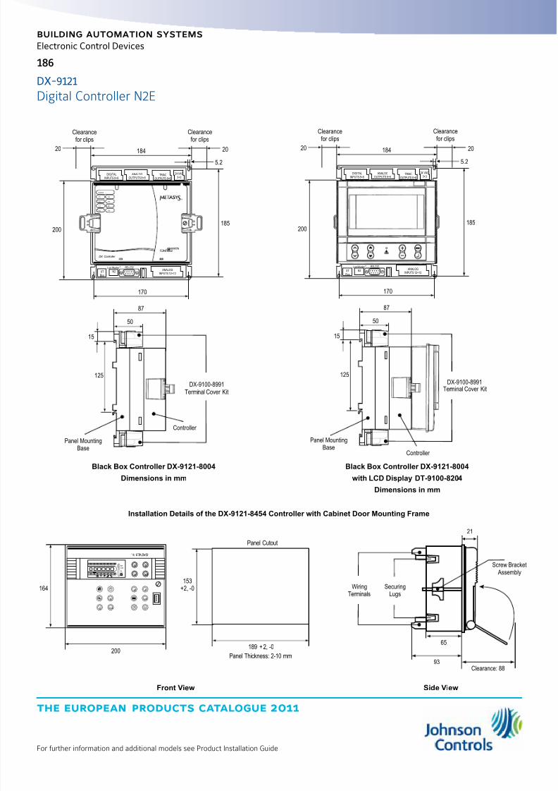
8/6/2019 Publ-6576 Prod Cat 11
http://slidepdf.com/reader/full/publ-6576-prod-cat-11 194/298
the european products catalogue 2011
For further information and additional models see Product Installation Guide
186
building automation systems
Electronic Control Devices
Black Box Controller DX-9121-8004
Dimensions in mm
DX-9100-8991Terminal Cover Kit
125
15
87
50
Panel MountingBase
DIGITAL
INPUTS 8+8
ANALOG
OUTPUTS 8+8
TRIAC
OUTPUTS 6+6
24 VAC
3+3
XT
Bus
ANALOG
INPUTS 12+12
RS-232Lon Works
N2
®
200
170
185
5.2
2020
DXADDR:
XT5
XT6
XT7
XT8
XT2
XT3
XT4
XT1
DX Controller
®
184
Clearance
for clips
Clearance
for clips
Controller
DIGITAL
INPUTS 8+8
ANALOG
OUTPUTS 8+8
TRIAC
OUTPUTS 6+6
24 VAC
3+3
XT
Bus
ANALOG
INPUTS 12+12
RS-232Lon Works
N2
®
Terminal Cover Kit
125
15
87
50
Panel MountingBase
200
170
185
5.2
2020 184
Clearance
for clips
Clearance
for clips
Controller
DX-9100-8991
Black Box Controller DX-9121-8004
with LCD Display DT-9100-8204
Dimensions in mm
Panel Thickness: 2-10 mm
Panel Cutout
R
YSMETAS
X D
Y
E ESC
XT
164
200
153
+2, -0
189 +2, -0
X D
Y
AZ
K
XT
A/M0
R/T
LON
AL
XT
+-0 1 01
K X Y Z D A/M
1 2 3 4 5 6 7 8
21
65
93Clearance: 88
WiringTerminals
SecuringLugs
Screw Bracket Assembly
Front View Side View
Installation Details of the DX-9121-8454 Controller with Cabinet Door Mounting Frame
DX-9121
Digital Controller N2E

8/6/2019 Publ-6576 Prod Cat 11
http://slidepdf.com/reader/full/publ-6576-prod-cat-11 195/298
the european products catalogue 2011
For further information and additional models see Product Installation Guide
187
building automation systems
Electronic Control Devices
DT-9100 Display Unit
Ordering Codes Description
DT-9100-8204 Display unit with panel mounting kit for DX-9121-800424 VAC ±10%, 4VA 50/60Hzor 9 to 12 VDC, 2 VA
DT-9100-8902 Display unit wall mounting kit
DT-9100-8901 12 VDC power supply for 230 VAC source
Software and Accessories
Ordering Codes Description
DX-9121-8997 Panel Mounting Base with Terminal Covers for DX-9121-8004 and DX-9121-8454
DX-9121-8996 Cabinet Door Mounting Frame for DX-9121-8454
DC-9100-8905 Access protection key for DX-9121-8454
DXDC-BAT-KIT Replacement battery kit
BAT-CR2032 Coin battery replacement
NoteFor DX Configuration Tools Software contact your local Johnson Controls office.
DX-9121
Digital Controller N2E

8/6/2019 Publ-6576 Prod Cat 11
http://slidepdf.com/reader/full/publ-6576-prod-cat-11 196/298
the european products catalogue 2011
For further information and additional models see Product Installation Guide
building automation systems
188
Electronic Control Devices
The LonWorks® compatible digital controller, DX-9200 Series, is the
ideal digital control solution for air handling unit or distributed lightingand related electrical equipment control applications. The controllerhas both the hardware and software flexibility to adapt to the varietyof control requirements in its targeted applications and can extend itsinput and output point capability by communicating with input/output(I/O) modules on an extension bus.
The controller provides monitoring and control of all connected pointsat an integral LED display and keyboard or from a separate DT-9100display unit. The DT-9100 display unit, with a text and graphic LCDscreen and keypad, provides a standard and customized presentation
of data according to the application and customer requirements.Both the DX-9200 controller and the DT-9100 display unit can bemounted within an electrical enclosure or in a cabinet door, andthe DT-9100 display unit can also be mounted directly onto thecontroller within a panel, on a wall or can be used as a portabledevice. Additionally, the controller can share data with other LonMark
® compatible devices on the same LonWorks network.When the LonWorks network is integrated into a Metasys® system,point and control information is available throughout the network andat all Metasys operator workstations.
Features z LonWorks
® compatible network variable interface FTT
z
Integration into Metasys system network via NAEz Dynamic data access capabilities with Metasys system network
z Full set of control algorithms in software modules
z Graphic configuration tool software
z Standalone control of HVAC and other equipment
z Real-time clock and time programs
z Extension bus for additional I/O points
z Extension modules for a variety of analog anddigital I/O combinations
z Model with integral display and control panel
z Text and graphic display unit (DT-9100)
z Extension modules with manual override switches
Dimensions in mmOrdering Codes Analog Inputs
BinaryInputs
AnalogOutputs
BinaryOutputs
Panel withLED Display
PowerSupply Application
DX-9200-8004-A
8 8 8 6
NO
(Black Box) 24 VAC ±10%,50/60Hz
Room and light control
DX-9200-8004-D Air handling control
DX-9200-8454-AYES
Room and light control
DX-9200-8454-D Air handling control
Jumper Selectable
RTD(1KΩ NI) 0-10 VDC Transmitter 0-20 mA Transmitter (4 max.)
DryContacts
Jumper Selectable
0-10 VDC 0-20 mA (4)
24 VAC Triacsat 0.5 amps
NoteRefer to DX-9200 Technical Bulletin for details of the LonWorks network interface specifications. LonWorks
® is a Registered Trade Mark of Echelon Corp.
DX-9200
Digital Controller
Metasys® Field Controllers LonWorks® Compatible
Model with LED display
and Keyboard in Cabinet Door
Mounting Frame
Black Box Model
on Panel Mounting Base
Clearance: 160 mm
DX-9100-8991
Terminal Cover Kit
125
15
95
DX-9121-8997
Base
R
Y SME T AS
DIGITAL
INPUTS 8+8
ANALOG
OUTPUTS 8+8
TRIAC
OUTPUTS6+6
24VAC
3+3
X D
Y
AZ
E ESC
K
XT
XT
Bus
ANALOG
INPUTS 12+12
RS-232
N2E
LONWORKS®
200
170
185
5.2
184
A/M0
R/T
LON
AL
XT
+-0 1 01
K X Y Z D A/M
1 2 3 4 5 6 7 8
Dimensions in mm

8/6/2019 Publ-6576 Prod Cat 11
http://slidepdf.com/reader/full/publ-6576-prod-cat-11 197/298
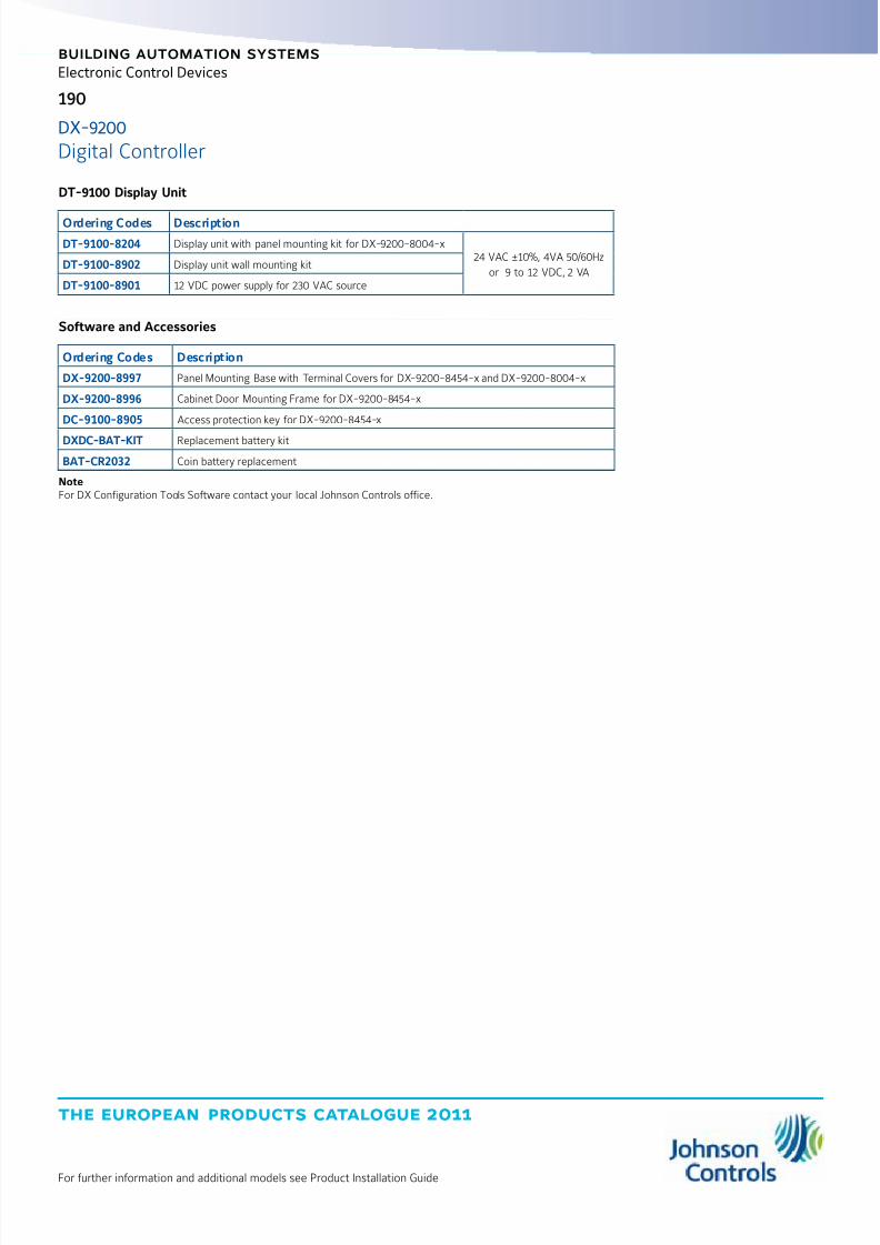
8/6/2019 Publ-6576 Prod Cat 11
http://slidepdf.com/reader/full/publ-6576-prod-cat-11 198/298
the european products catalogue 2011
For further information and additional models see Product Installation Guide
190
building automation systems
Electronic Control Devices
DT-9100 Display Unit
Ordering Codes Description
DT-9100-8204 Display unit with panel mounting kit for DX-9200-8004-x24 VAC ±10%, 4VA 50/60Hz
or 9 to 12 VDC, 2 VADT-9100-8902 Display unit wall mounting kit
DT-9100-8901 12 VDC power supply for 230 VAC source
Software and Accessories
Ordering Codes Description
DX-9200-8997 Panel Mounting Base with Terminal Covers for DX-9200-8454-x and DX-9200-8004-x
DX-9200-8996 Cabinet Door Mounting Frame for DX-9200-8454-x
DC-9100-8905 Access protection key for DX-9200-8454-x
DXDC-BAT-KIT Replacement battery kit
BAT-CR2032 Coin battery replacement
NoteFor DX Configuration Tools Software contact your local Johnson Controls office.
DX-9200
Digital Controller
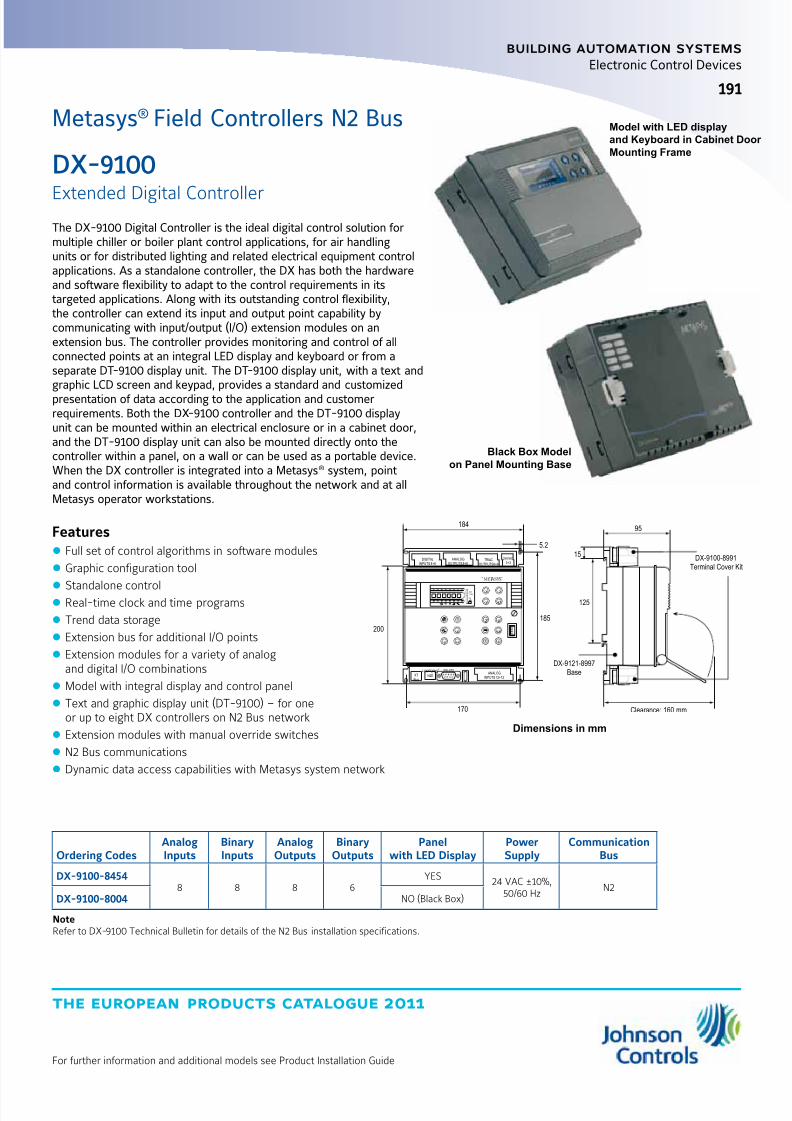
8/6/2019 Publ-6576 Prod Cat 11
http://slidepdf.com/reader/full/publ-6576-prod-cat-11 199/298
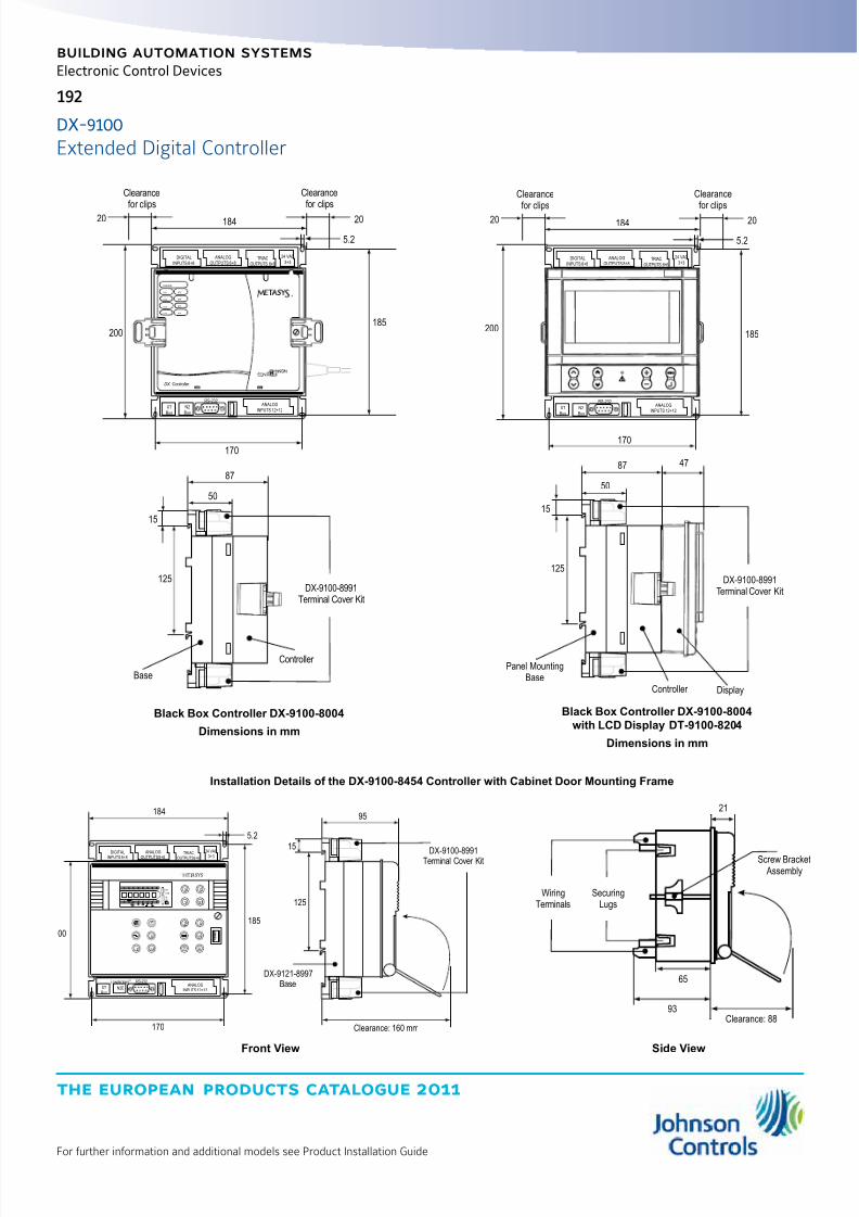
8/6/2019 Publ-6576 Prod Cat 11
http://slidepdf.com/reader/full/publ-6576-prod-cat-11 200/298
the european products catalogue 2011
For further information and additional models see Product Installation Guide
192
building automation systems
Electronic Control Devices
DX-9100-8991Terminal Cover Kit
Display
47
Panel MountingBase
DIGITAL
INPUTS 8+8
ANALOG
OUTPUTS 8+8
TRIAC
OUTPUTS 6+6
24 VAC
3+3
XT
Bus
ANALOG
INPUTS 12+12
RS-232
N2
Bus
125
15
87
50
200
170
185
5.2
2020 184
Clearancefor clips
Clearancefor clips
Controller
DX-9100-8991Terminal Cover Kit
DIGITAL
INPUTS 8+8
ANALOG
OUTPUTS 8+8
TRIAC
OUTPUTS 6+6
24 VAC
3+3
XT
Bus
ANALOG
INPUTS 12+12
RS-232
N2
Bus
DXADDR:
XT5
XT6
XT7
XT8
XT2
XT3
XT4
XT1
DX Controller
®
125
15
87
50
Base
200
170
185
5.2
2020 184
Clearancefor clips
Clearancefor clips
Controller
Black Box Controller DX-9100-8004
Dimensions in mm
Black Box Controller DX-9100-8004
with LCD Display DT-9100-8204
Dimensions in mm
Clearance: 160 mm
DX-9100-8991Terminal Cover Kit
125
15
95
DX-9121-8997
Base
R
Y SME T AS
DIGITALINPUTS 8+8
ANALOGOUTPUTS 8+8
TRIACOUTPUTS6+6
24 VAC
3+3
X D
Y
AZ
E ESC
K
XT
XT
Bus
ANALOG
INPUTS 12+12
RS-232
N2E
LONWORKS®
00
170
185
5.2
184
A/M0
R/T
LON
AL
XT
+-0 1 01
K X Y Z D A/M
1 2 3 4 5 6 7 8
21
65
93Clearance: 88
WiringTerminals
SecuringLugs
Screw Bracket Assembly
Front View Side View
Installation Details of the DX-9100-8454 Controller with Cabinet Door Mounting Frame
DX-9100
Extended Digital Controller

8/6/2019 Publ-6576 Prod Cat 11
http://slidepdf.com/reader/full/publ-6576-prod-cat-11 201/298
the european products catalogue 2011
For further information and additional models see Product Installation Guide
193
building automation systems
Electronic Control Devices
DT-9100 Display Unit
Ordering Codes Description
DT-9100-8204 Display unit with panel mounting kit for DX-9100-800424 VAC ±10%, 4 VA 50/60 Hz
or 9 to 12 VDC, 2 VADT-9100-8902 Display unit wall mounting kit
DT-9100-8901 12 VDC power supply for 230 VAC source
Software and Accessories
Ordering Codes Description
DX-9100-8997 Panel Mounting Base with Terminal covers for DX-9100-8454 and DX-9100-8004
DX-9100-8996 Cabinet Door Mounting Frame for DX-9100-8454
DC-9100-8905 Access protection key for DX-9100-8154 and DX-9100-8454
DXDC-BAT-KIT Replacement battery kit
BAT-CR2032 Coin battery replacement
Note:For DX Configuration Tools Software contact your local Johnson Controls office.
DX-9100
Extended Digital Controller

8/6/2019 Publ-6576 Prod Cat 11
http://slidepdf.com/reader/full/publ-6576-prod-cat-11 202/298

8/6/2019 Publ-6576 Prod Cat 11
http://slidepdf.com/reader/full/publ-6576-prod-cat-11 203/298
the european products catalogue 2011
For further information and additional models see Product Installation Guide
195
building automation systems
195
Electronic Control Devices
The Variable Air Volume Modular Assembly (VMA) is a family of configurable digital controllers. Differing models in the VMA1400 seriescombine a controller, pressure sensor and/or actuator housed in onepre-assembled unit.
The VMA1400 series is available in four models:
z Cooling Only (VMA1410)
z Cooling with Reheat and/or Fan
z (VMA1420)
z External Actuator (VMA1430)The VMA1410, 1420, 1430 are designed for pressure-independent,
single duct systems. The VMA1420 and VMA1430 can also be usedwith parallel or series fan powered boxes, supply/exhaust applications,and dual duct systems.
Features z Easy-to-handle unit with a compact footprint
z Pre-wired controller with pressure sensor and actuator for reducedinstallation time
z Fast response actuator that drives the damper from full open to fullclosed (90°)
z Continuous loop tuning through proportional adaptive algorithms usingpatented P-Adaptive and Pattern Recognition Adaptive Control (PRAC)
Ordering Codes Inputs / Outputs Point Rating
Model
Description1410 1420 1430
Analog Inputs
AP-VMA1410-0
Zone temperature AI-1 1K Ni,Si, Pt, or 2.25 K NTC Integrated VAV
Controller/Actuator/Pressure sensor(cooling only)
Zone setpoint AI-2 1.6 Kohm pot.meter
Sideloop (humidity, dew point) AI-3 0..10 VDC ---
AP-VMA1420-0Supply air temp. or supplemental
heat temp.AI-4 1K Ni,Si, Pt, or 2.25 K NTC
Integrated VAVController/Actuator/Pressure sensor(w/ Reheat and Fan-Powered)
AP-VMA1430-0 Velocity pressure internal 0…374 pa
Integrated VAVController/Pressure sensor(w/ Reheat and Fan-Powered)
Binary Inputs
Tempory occupied/Standby BI-1
Dry contact
Occupied BI-2
Off or window or shutdown BI-3 ---
Analog Outputs
Proportional heatAO-1AO-2
0…10 VDC at 10 mA ---
Binary OutputsLights, Fan, Box Heat-Valve or1-3 stage Electric, Supplement
Heat-Valve or Single StageElectric Box Heat, External
Damper Actuator,
BO-1BO-2BO-3BO-4BO-5
24 VAC at 0.5 A each ---
Stepper Motor with PositionActuator
Internal 2-phase Stepper ---
VMA1400
Variable Air Volume Controller
Metasys® Field Controllers n2 Bus

8/6/2019 Publ-6576 Prod Cat 11
http://slidepdf.com/reader/full/publ-6576-prod-cat-11 204/298
the european products catalogue 2011
Manufacturer reserved the rights to change specifications without prior notice
Notes
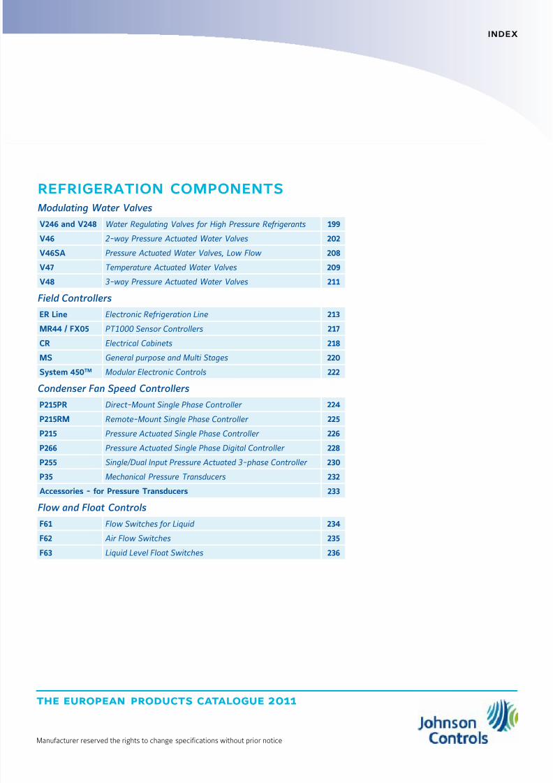
8/6/2019 Publ-6576 Prod Cat 11
http://slidepdf.com/reader/full/publ-6576-prod-cat-11 205/298
the european products catalogue 2011
Manufacturer reserved the rights to change specifications without prior notice
index
refrigeration components
Modulating Water Valves
V246 and V248 Water Regulating Valves for High Pressure Refrigerants 199
V46 2-way Pressure Actuated Water Valves 202
V46SA Pressure Actuated Water Valves, Low Flow 208
V47 Temperature Actuated Water Valves 209
V48 3-way Pressure Actuated Water Valves 211
Field Controllers
ER Line Electronic Refrigeration Line 213
MR44 / FX05 PT1000 Sensor Controllers 217
CR Electrical Cabinets 218
MS General purpose and Multi Stages 220
System 450TM Modular Electronic Controls 222
Condenser Fan Speed Controllers
P215PR Direct-Mount Single Phase Controller 224
P215RM Remote-Mount Single Phase Controller 225
P215 Pressure Actuated Single Phase Controller 226
P266 Pressure Actuated Single Phase Digital Controller 228
P255 Single/Dual Input Pressure Actuated 3-phase Controller 230
P35 Mechanical Pressure Transducers 232
Accessories - for Pressure Transducers 233
Flow and Float Controls
F61 Flow Switches for Liquid 234
F62 Air Flow Switches 235
F63 Liquid Level Float Switches 236
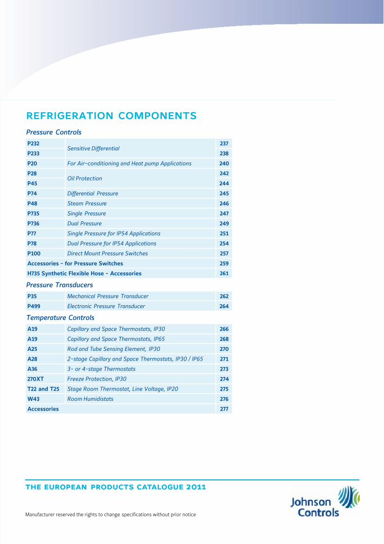
8/6/2019 Publ-6576 Prod Cat 11
http://slidepdf.com/reader/full/publ-6576-prod-cat-11 206/298
the european products catalogue 2011
Manufacturer reserved the rights to change specifications without prior notice
refrigeration components
Pressure Controls
P232Sensitive Differential
237
P233 238
P20 For Air-conditioning and Heat pump Applications 240
P28Oil Protection
242
P45 244
P74 Differential Pressure 245
P48 Steam Pressure 246
P735 Single Pressure 247
P736 Dual Pressure 249
P77 Single Pressure for IP54 Applications 251
P78 Dual Pressure for IP54 Applications 254
P100 Direct Mount Pressure Switches 257
Accessories - for Pressure Switches 259
H735 Synthetic Flexible Hose - Accessories 261
Pressure Transducers P35 Mechanical Pressure Transducer 262
P499 Electronic Pressure Transducer 264
Temperature Controls
A19 Capillary and Space Thermostats, IP30 266
A19 Capillary and Space Thermostats, IP65 268
A25 Rod and Tube Sensing Element, IP30 270
A28 2-stage Capillary and Space Thermostats, IP30 / IP65 271
A36 3- or 4-stage Thermostats 273
270XT Freeze Protection, IP30 274T22 and T25 Stage Room Thermostat, Line Voltage, IP20 275
W43 Room Humidistats 276
Accessories 277

8/6/2019 Publ-6576 Prod Cat 11
http://slidepdf.com/reader/full/publ-6576-prod-cat-11 207/298
the european products catalogue 2011
For further information and additional models see Product Bulletin
199199
refrigeration components
Modulating Water Valves
The V246 & V248 Series 2-way and 3-Way Pressure-Actuated Water-Regulating Valves for High-Pressure Refrigerants regulate water flowand control refrigerant head pressure in systems with single or multiplewatercooled condensers.
These valves have an adjustable opening point in a refrigerant pressurerange of 200 to 400 psig (13.8 to 27.6 bar).
These Series valves are designed specifically for condensing unitscooled either by atmospheric or forced draft cooling towers.They are used on single or multiple condenser hook-ups to the towerto provide the most economical and efficient use of the tower.V246 & V248 valves may be used with standard non-corrosive or
ammonia refrigerants.For applications where the coolant may be corrosive to the internalparts, maritime models are available, which have nickel copper(Monel®) internal parts.
Features z No Close Fitting or Sliding Parts in Water Passages
z Accessible Range Spring
z Take-Apart Construction
z Pressure-Balanced Design
z Corrosion-Resistant Material for Internal Parts
V246 and V248
Water Regulating Valves for High Pressure Refrigerants
V246 Screw Connection Valves Dimensions
Valve Size
Dimensions in mm
A B C D E
3/8 in. 67 41 166 89 77
1/2 in. 78 51 182 96 86
3/4 in. 86 55 203 106 98
1 in.121 71
267 151 116
1-1/4 in. 276 156 121

8/6/2019 Publ-6576 Prod Cat 11
http://slidepdf.com/reader/full/publ-6576-prod-cat-11 208/298
the european products catalogue 2011
For further information and additional models see Product Bulletin
200
refrigeration components
Modulating Water Valves
V246 Flange Valve, Commercial Service - Dimensions
Valve SizeDimensions in mm
A B C D E F G H
1-1/2 in. 135 14 156 121 276 133 67 48
V246 Flange Valve, Commercial Service - Flange Specifications(European, DIN2533 Flanges)
Valve Size Number of Holes Hole Size Bolt Circle
1-1/2 in. 135 14 156
V246 Flange Valve, Maritime Service - Dimensions
Valve Size
Dimensions in mm
A B C D E F G H
1-1/2 in. 135 14 156 121 276 133 67 48
V246 Flange Valve, Maritime Service - Flange Specifications(European, DIN86021 Flanges)
Valve Size Number of Holes Hole Size Bolt Circle
1-1/2 in. 135 14 156
Standard Production Models - Range 13.8 to 27.6 barProduct Codes Construction Valve Size and Connection Element Style Shipping Weight (kg)
V246GA1A001C
Direct Acting, Commercial
3/8 in. BSPP Screw, ISO 228
Style 5
1.86
V246GB1A001C 1/2 in. BSPP Screw, ISO 228 1.4
V246GC1A001C 3/4 in. BSPP Screw, ISO 228 1.7
V246GD1B1001C 1 in. BSPT Screw, ISO 7 4.2
V246GE1B1001C 1-1/4 in. BSPT Screw, ISO 7 4.5
V246GR1B1001C 1-1/2 in. Flange, DIN2533 6.2
V246HA1B001C
Direct Acting, Maritime
3/8 in. BSPP Screw, ISO 228 1.86
V246HB1B001C 1/2 in. BSPP Screw, ISO 228 1.4
V246HC1B001C 3/4 in. BSPP Screw, ISO 228 2.0
V246HD1B001C 1 in. BSPT Screw, ISO 228 4.3V246HE1B001C 1-1/4 in. BSPT Screw, ISO 228 4.7
V246HR1B001C 1-1/2 in. Flange, DIN86021 6.2
V246Water Regulating Valves for High Pressure Refrigerants
Style 5
7/16-20 UNF
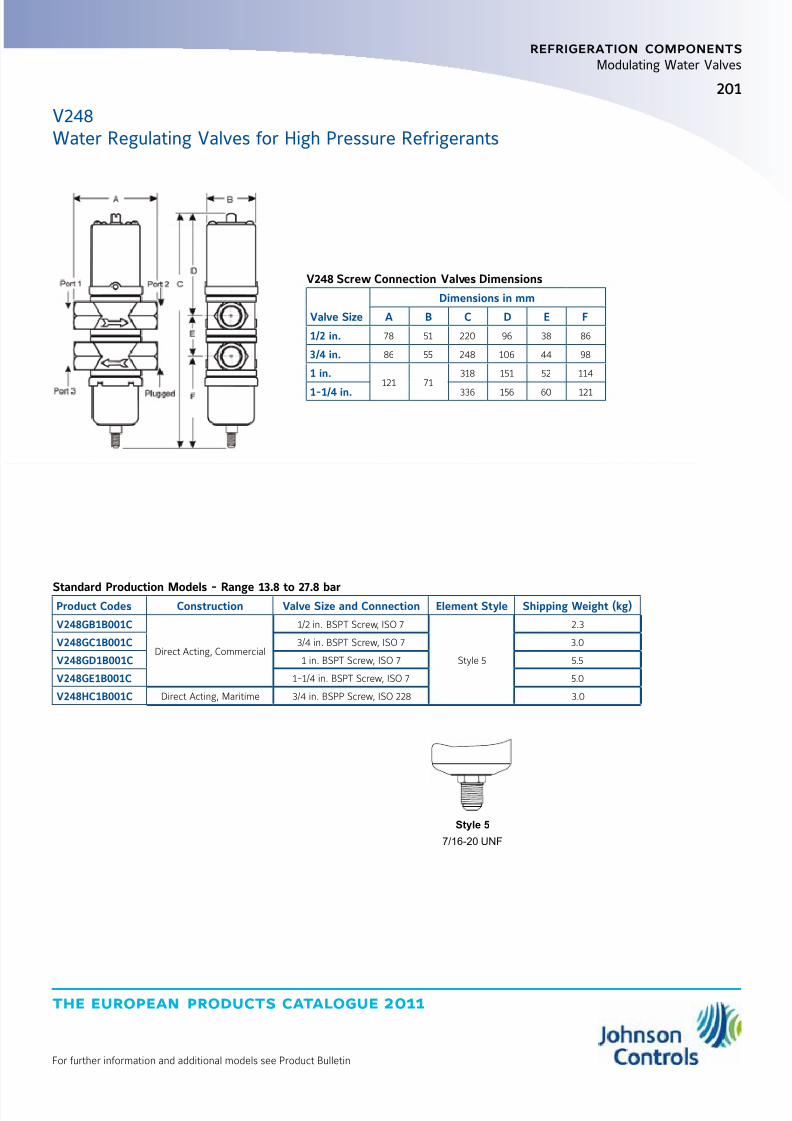
8/6/2019 Publ-6576 Prod Cat 11
http://slidepdf.com/reader/full/publ-6576-prod-cat-11 209/298
the european products catalogue 2011
For further information and additional models see Product Bulletin
201
refrigeration components
Modulating Water Valves
V248Water Regulating Valves for High Pressure Refrigerants
V248 Screw Connection Valves Dimensions
Valve Size
Dimensions in mm
A B C D E F
1/2 in. 78 51 220 96 38 86
3/4 in. 86 55 248 106 44 98
1 in.121 71
318 151 52 114
1-1/4 in. 336 156 60 121
Standard Production Models - Range 13.8 to 27.8 barProduct Codes Construction Valve Size and Connection Element Style Shipping Weight (kg)
V248GB1B001C
Direct Acting, Commercial
1/2 in. BSPT Screw, ISO 7
Style 5
2.3
V248GC1B001C 3/4 in. BSPT Screw, ISO 7 3.0
V248GD1B001C 1 in. BSPT Screw, ISO 7 5.5
V248GE1B001C 1-1/4 in. BSPT Screw, ISO 7 5.0
V248HC1B001C Direct Acting, Maritime 3/4 in. BSPP Screw, ISO 228 3.0
Style 5
7/16-20 UNF

8/6/2019 Publ-6576 Prod Cat 11
http://slidepdf.com/reader/full/publ-6576-prod-cat-11 210/298
the european products catalogue 2011
For further information and additional models see Product Bulletin
202
refrigeration components
Modulating Water Valves
These pressure actuated modulating valves control the quantityof water to a condenser by directly sensing pressure changes in arefrigerant circuit.
The valves can be used in non-corrosive refrigerant systems.Ammonia power elements and valves designed for salt-waterapplications are available.
The valves have a quick opening characteristic and openon pressure increase (direct acting).Reverse acting (close on pressure increase) is possible.
Features z Pressure balanced valve design
z Pressure actuated
z 3/8, 1/2, 3/4” are angled body type valves with high Kv value
z 3/8” up to 2” pressure valves “all range” types
z Quick opening valve characteristics
z No close fitting or sliding parts in water passages
z Easy to disassemble. All parts can be replaced
z Special bronze bodies and monel parts
z Power elements with stainless steel bellows available
z Wide range of pressure connection styles
z Nickel plated seats available for 3/8, 1/2, and 3/4” valves
z Direct/reverse action
V46
B
F
C D
AE
Valve Size
Dimensions in mm
A B C D E F
3/8“ 69 153 66 43 18 89
1/2“ 80 170 86 51 27 100
3/4“ 91 183 95 55 36 110
2-way Pressure Actuated Water Valves - Commercial Applications
1 2
Style 13
(excl. valve depressor)
1: 75 cm capillary
2: 7/16-20 UNF flare nut
2a1
Style 34
1: 75 cm capillary
2: 1/4” tube for braze connection
1 32
Style 50
(incl. valve depressor mounted
into machined flare)
1: 75 cm capillary
2: 1/4” tube for braze connection
3: copper sealring
Style 15
1/4-18NPT (female)
Style 5
7/16-20 UNF

8/6/2019 Publ-6576 Prod Cat 11
http://slidepdf.com/reader/full/publ-6576-prod-cat-11 211/298
the european products catalogue 2011
For further information and additional models see Product Bulletin
203
refrigeration components
Modulating Water Valves
V462-way Pressure Actuated Water Valves - Commercial Applications
Ordering Codes Range(bar) BodyStyle
Size Thread
accordingto ISO 228 Style
Capillary
Length(cm)
Additional Features
It is possible to change Style 13 intoStyle 45A by ordering KIT031N600
V46AA -9600
5…18 Angled
3/8“
1375
---
V46AA -9608*With special washer to prevent waterhammerat low flow capacity
V46AA -9602* 100 Nickel plated seat/longer capillary
V46AA –995034
75
Nickel plated seat/solder connection
V46AA -9951* .040” i.d.cap./solder connection
V46AB –96001/2“
13 ---
V46AB –9950 34 Solder connection/“062” id.cap
V46AC –96003/4“
13 ---
V46AC –9951 34 Solder connection
V46AA –9300
5…23 Angled
3/8“
5 ---
---
V46AA –9301*Nickel plated seat, high range.With washer to prevent waterhammer at low flow capacity
V46AA –960613
75
Nickel plated seat, high range
V46AA -9609*Nickel plated seat, high range.With washer to prevent waterhammer at low flow capacity
V46AA –9510 50 High range
V46AB –9300
1/2“
5 --- ---
V46AB –9605 13
75
Nickel plated seat, high range
V46AB -9951 34 Solder connection, high range
V46AB -9510 50 High range
V46AC -93003/4“
5 ---V46AC -9605 13 Nickel plated seat, high range
V46AC -9510 50 High range
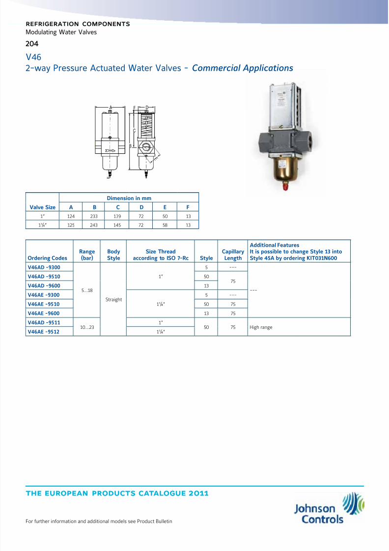
8/6/2019 Publ-6576 Prod Cat 11
http://slidepdf.com/reader/full/publ-6576-prod-cat-11 212/298
the european products catalogue 2011
For further information and additional models see Product Bulletin
204
refrigeration components
Modulating Water Valves
Valve Size
Dimension in mm
A B C D E F
1“ 124 233 139 72 50 13
1¼“ 125 243 145 72 58 13
Ordering CodesRange(bar)
BodyStyle
Size Threadaccording to ISO 7-Rc Style
CapillaryLength
Additional FeaturesIt is possible to change Style 13 intoStyle 45A by ordering KIT031N600
V46AD -9300
5…18
Straight
1”
5 ---
---
V46AD -9510 5075
V46AD -9600 13
V46AE -9300
1¼“
5 ---
V46AE -9510 50 75
V46AE -9600 13 75
V46AD -951110…23
1”50 75 High range
V46AE -9512 1¼“
B
C
FA D
E
V462-way Pressure Actuated Water Valves - Commercial Applications
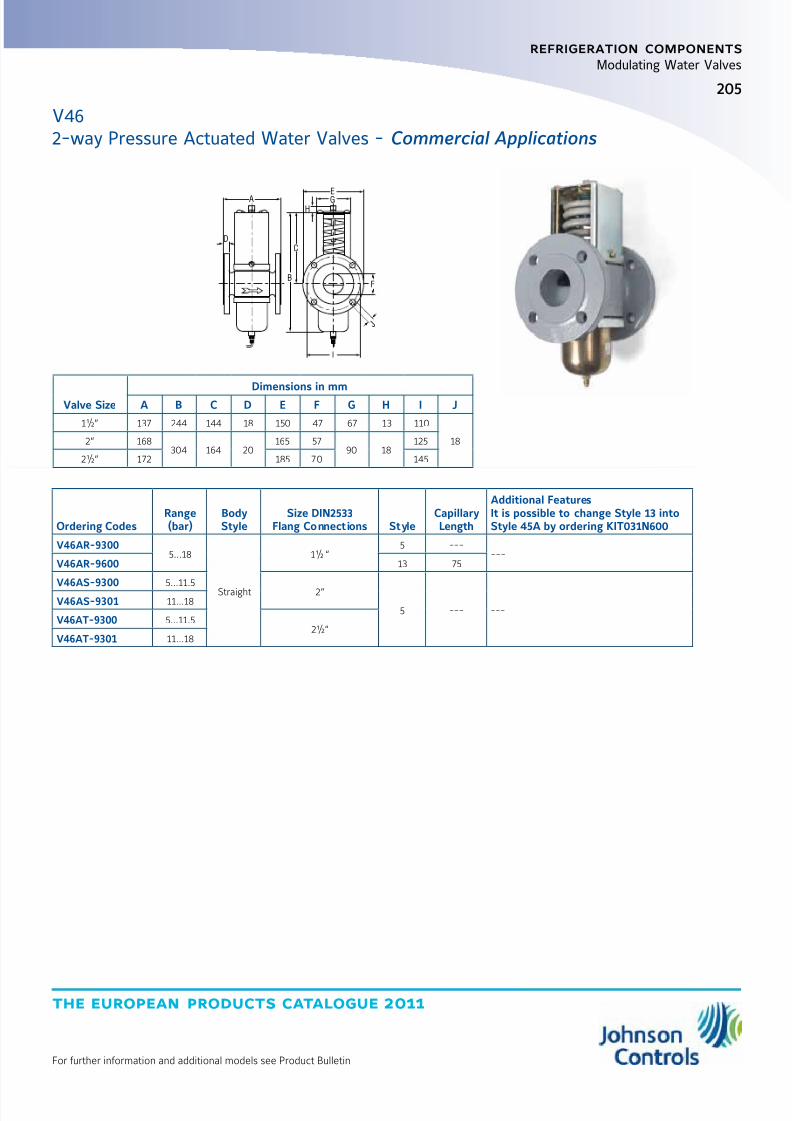
8/6/2019 Publ-6576 Prod Cat 11
http://slidepdf.com/reader/full/publ-6576-prod-cat-11 213/298
the european products catalogue 2011
For further information and additional models see Product Bulletin
205
refrigeration components
Modulating Water Valves
Valve Size Dimensions in mmA B C D E F G H I J
1½“ 137 244 144 18 150 47 67 13 110
182“ 168304 164 20
165 5790 18
125
2½“ 172 185 70 145
Ordering CodesRange(bar)
BodyStyle
Size DIN2533Flang Connections Style
CapillaryLength
Additional FeaturesIt is possible to change Style 13 intoStyle 45A by ordering KIT031N600
V46AR-93005…18
Straight
1½ “5 ---
---V46AR-9600 13 75
V46AS-9300 5…11.52“
5 --- ---V46AS-9301 11…18
V46AT-9300 5…11.52½“
V46AT-9301 11…18
A
B
C
D
F
G
H
J
I
E
V462-way Pressure Actuated Water Valves - Commercial Applications
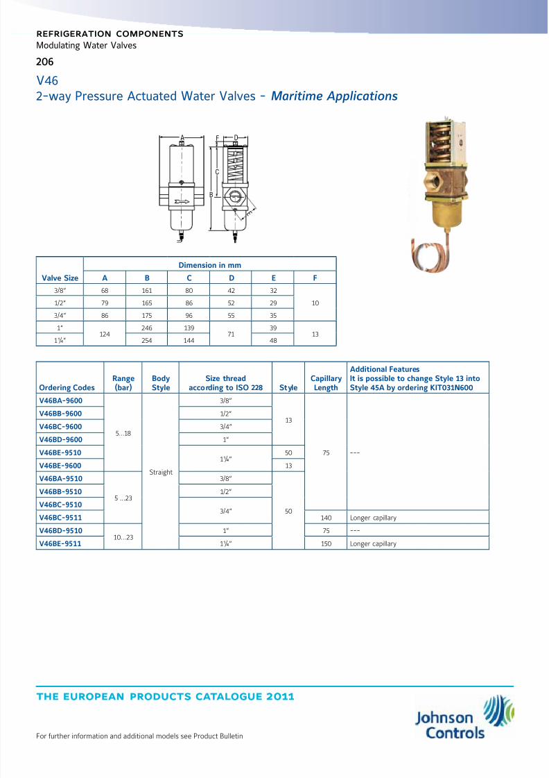
8/6/2019 Publ-6576 Prod Cat 11
http://slidepdf.com/reader/full/publ-6576-prod-cat-11 214/298
the european products catalogue 2011
For further information and additional models see Product Bulletin
206
refrigeration components
Modulating Water Valves
Ordering CodesRange(bar)
BodyStyle
Size threadaccording to ISO 228 Style
CapillaryLength
Additional FeaturesIt is possible to change Style 13 intoStyle 45A by ordering KIT031N600
V46BA-9600
5…18
Straight
3/8“
13
75 ---
V46BB-9600 1/2“
V46BC-9600 3/4“
V46BD-9600 1“
V46BE-95101¼“
50
V46BE-9600 13
V46BA-9510
5 …23
3/8“
50
V46BB-9510 1/2“
V46BC-95103/4“
V46BC-9511 140 Longer capillary
V46BD-951010…23
1“ 75 ---
V46BE-9511 1¼“ 150 Longer capillary
Valve Size
Dimension in mm
A B C D E F
3/8“ 68 161 80 42 32
101/2“ 79 165 86 52 29
3/4“ 86 175 96 55 35
1“124
246 13971
3913
1¼“ 254 144 48
B
C
FA D
E
V462-way Pressure Actuated Water Valves - Maritime Applications
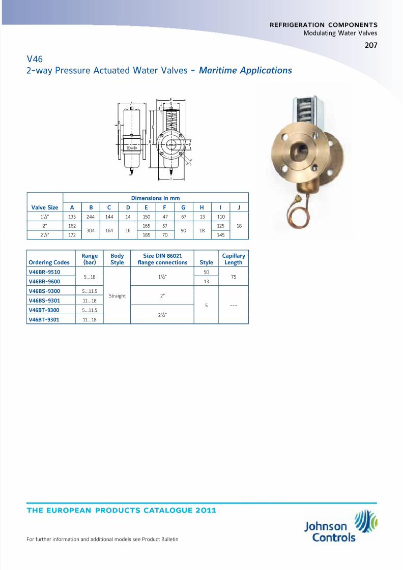
8/6/2019 Publ-6576 Prod Cat 11
http://slidepdf.com/reader/full/publ-6576-prod-cat-11 215/298
the european products catalogue 2011
For further information and additional models see Product Bulletin
207
refrigeration components
Modulating Water Valves
Ordering CodesRange(bar)
BodyStyle
Size DIN 86021flange connections Style
CapillaryLength
V46BR-95105…18
Straight
1½“50
75V46BR-9600 13
V46BS-9300 5…11.52“
5 ---V46BS-9301 11…18
V46BT-9300 5…11.52½“
V46BT-9301 11…18
Valve SizeDimensions in mm
A B C D E F G H I J
1½“ 135 244 144 14 150 47 67 13 110
182“ 162304 164 16
165 5790 18
125
2½“ 172 185 70 145
A
B
C
D
F
G
H
J
I
E
V462-way Pressure Actuated Water Valves - Maritime Applications
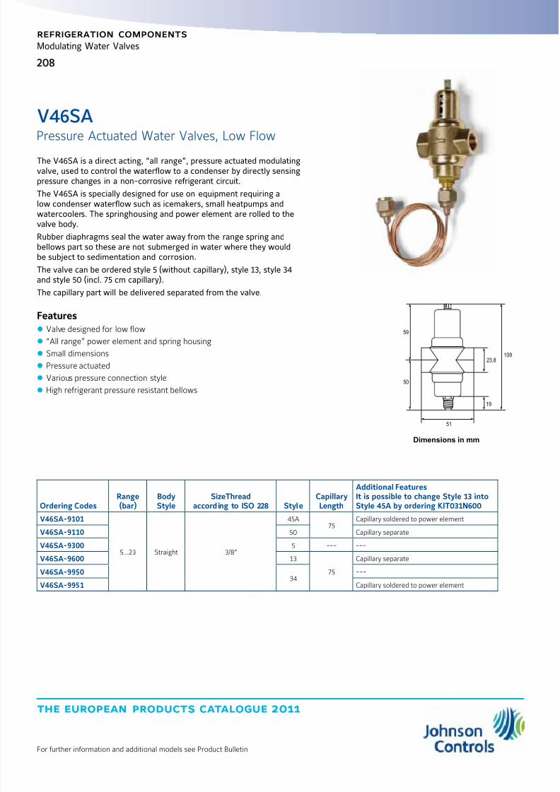
8/6/2019 Publ-6576 Prod Cat 11
http://slidepdf.com/reader/full/publ-6576-prod-cat-11 216/298
the european products catalogue 2011
For further information and additional models see Product Bulletin
208
refrigeration components
Modulating Water Valves
The V46SA is a direct acting, “all range”, pressure actuated modulatingvalve, used to control the waterflow to a condenser by directly sensingpressure changes in a non-corrosive refrigerant circuit.
The V46SA is specially designed for use on equipment requiring alow condenser waterflow such as icemakers, small heatpumps andwatercoolers. The springhousing and power element are rolled to thevalve body.
Rubber diaphragms seal the water away from the range spring andbellows part so these are not submerged in water where they wouldbe subject to sedimentation and corrosion.
The valve can be ordered style 5 (without capillary), style 13, style 34
and style 50 (incl. 75 cm capillary).The capillary part will be delivered separated from the valve.
Features z Valve designed for low flow
z “All range” power element and spring housing
z Small dimensions
z Pressure actuated
z Various pressure connection style
z High refrigerant pressure resistant bellows
Ordering CodesRange(bar)
BodyStyle
SizeThreadaccording to ISO 228 Style
CapillaryLength
Additional FeaturesIt is possible to change Style 13 intoStyle 45A by ordering KIT031N600
V46SA-9101
5…23 Straight 3/8“
45A75
Capillary soldered to power element
V46SA-9110 50 Capillary separate
V46SA-9300 5 --- ---
V46SA-9600 13
75
Capillary separate
V46SA-995034
---
V46SA-9951 Capillary soldered to power element
Dimensions in mm
23.8
59
50
109
51
19
V46SA
Pressure Actuated Water Valves, Low Flow
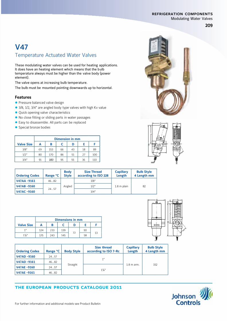
8/6/2019 Publ-6576 Prod Cat 11
http://slidepdf.com/reader/full/publ-6576-prod-cat-11 217/298
the european products catalogue 2011
For further information and additional models see Product Bulletin
209209
refrigeration components
Modulating Water Valves
Valve Size
Dimensions in mm
A B C D E F1“ 124 233 139
7250
131¼“ 125 243 145 58
Ordering Codes Range °C Body StyleSize thread
according to ISO 7-RcCapillaryLength
Bulb Style4 Length mm
V47AD -9160 24…57
Straight
1“
1.8 m arm. 152V47AD -9161 46…82
V47AE -9160 24…571¼“
V47AE -9161 46…82
B
C
FA D
E
Ordering Codes Range °CBodyStyle
Size Threadaccording to ISO 228
CapillaryLength
Bulb Style4 Length mm
V47AA -9161 46…82
Angled
3/8“
1.8 m plain 82V47AB -916024…57
1/2“
V47AC -9160 3/4“
Valve Size
Dimension in mm
A B C D E F
3/8“ 69 153 66 43 18 89
1/2“ 80 170 86 51 27 100
3/4“ 91 183 95 55 36 110
B
F
C D
AE
These modulating water valves can be used for heating applications.It does have an heating element which means that the bulbtemperature always must be higher than the valve body (powerelement).
The valve opens at increasing bulb temperature.
The bulb must be mounted pointing downwards up to horizontal.
Features z Pressure balanced valve design
z 3/8, 1/2, 3/4” are angled body type valves with high Kv value
z Quick opening valve characteristics z No close fitting or sliding parts in water passages
z Easy to disassemble. All parts can be replaced
z Special bronze bodies
V47
Temperature Actuated Water Valves
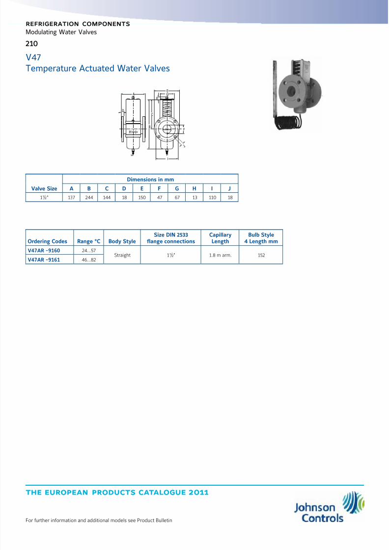
8/6/2019 Publ-6576 Prod Cat 11
http://slidepdf.com/reader/full/publ-6576-prod-cat-11 218/298
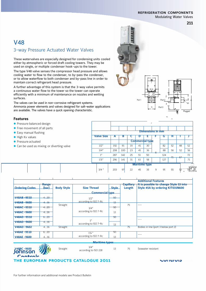
8/6/2019 Publ-6576 Prod Cat 11
http://slidepdf.com/reader/full/publ-6576-prod-cat-11 219/298
the european products catalogue 2011
For further information and additional models see Product Bulletin
211211
refrigeration components
Modulating Water Valves
These watervalves are especially designed for condensing units cooledeither by atmospheric or forced draft cooling towers. They may beused on single, or multiple condenser hook-ups to the tower.
The type V48 valve senses the compressor head pressure and allowscooling water to flow to the condenser, to by-pass the condenser,or to allow waterflow to both condenser and by-pass line in order tomaintain correct refrigerant head pressure.
A further advantage of this system is that the 3-way valve permitsa continuous water flow to the tower so the tower can operateefficiently with a minimum of maintenance on nozzles and wettingsurfaces.
The valves can be used in non-corrosive refrigerant systems.Ammonia power elements and valves designed for salt-water applicationsare available. The valves have a quick opening characteristic.
Features z Pressure balanced design
z Free movement of all parts
z Easy manual flushing
z High Kv values
z Pressure actuated
z Can be used as mixing or diverting valve
Ordering CodesRange(bar) Body Style Size Thread Style
CapillaryLength
Additional FeaturesIt is possible to change Style 13 intoStyle 45A by ordering KIT031N600
Commercial type
V48AB -9510 4…20
Straight
1/2“according to ISO 7-Rc
50
75 ---V48AB -96004…16 13
V48AC -9510 4…20 3/4“according to ISO 7-Rc
50
V48AC -9600 4…16 13
V48AD -9510 6…20
Straight
1“according to ISO 7-Rc
50
75
---V48AD -9600 4…16
13V48AD -9602 4…16 Bodies in line (port 3 below port 2)
V48AE -9510 6…20 1¼ “according to ISO 7-Rc
50---
V48AE -9600 4…16 13
Maritime types
V48BC -9600 4…16 Straight3/4“
according to ISO 22813 75 Seawater resistant
Valve Size
Dimensions in mm
A B C D E F G H I J
Commercial type
1/2“ 192 91 19 41 30
8
82 52 48 52
3/4“ 208 100 23 45 36 88 56 52 56
1“ 287 142 25 51 50 12471 67
72
1¼“ 296 141 31 61 58 127 71
Maritime type
3/4 “ 203 97 22 45 35 9 95 55 52 55
V48
3-way Pressure Actuated Water Valves
Port 2
Port 3
Plugged
Port 1
GI
A
B
C
F
D
E
H
J

8/6/2019 Publ-6576 Prod Cat 11
http://slidepdf.com/reader/full/publ-6576-prod-cat-11 220/298
the european products catalogue 2011
For further information and additional models see Product Bulletin
212
refrigeration components
Modulating Water Valves
Commercial types
Ordering Codes Range (bar)BodyStyle
Size Threadaccording to ISO 228 Style
Additional FeaturesIt is possible to change Style 13 intoStyle 45A by ordering KIT031N600
V48AF-9300 6…14 Straight 1 1/2“ 5 ---
126
187 P o r t 1
Port 2
Port 3
15495
8877
67
360
157
V483-way Pressure Actuated Water Valves

8/6/2019 Publ-6576 Prod Cat 11
http://slidepdf.com/reader/full/publ-6576-prod-cat-11 221/298
the european products catalogue 2011
For further information and additional models see Product Bulletin
213213
refrigeration components
Field Controllers
Devices are designed to be incorporated in refrigerated display casesand cold storage rooms.
ER Line proposes progressive offer from basic controls to advancedcontrols including real time clock, energy saving and networkcommunication to be integrated with monitoring system.
It also introduces specific products for supermarkets(e.g. compressor rack).
Hardware Features z Robust front panel for durability and long term usage
z Direct 230V supply, no external transformer required z Up to 5 relays in a single package
z NTC or PTC (A99) sensors
z Removable plug connectors for quick mounting and wiring
z Embedded real time clock, no additional clock card required
z Embedded RS485 port, no additional communication card required
Application Features z Positive or negative temperature units with a single product
z Minimum and maximum temperature monitoring
z Comprehensive controls
z Light and standby switching
z Energy saving (2nd setpoint)
ER LINE
Electronic Refrigeration Line
Product Type Mounting WiringCompressor
RelaysFan
RelaysDefrostRelays
AuxiliaryRelays
Real TimeClock RS485
ER52 Evaporator Control Panel Fixed screw connectors
ER53 Evaporator Control Panel Fixed screw connectors
ER54 Evaporator Control Panel Removable plug connectors
ER55-DR Cold Room Control Din Rail Removable plug connectors
(2 Relays)
ER55-SM Cold Room Control Split Fixed Screw connectors
(2 Relays)
ER65 Rack Control Din Rail Removable plug connectors (4 Relays)
Please refer to product bulletins for complete information

8/6/2019 Publ-6576 Prod Cat 11
http://slidepdf.com/reader/full/publ-6576-prod-cat-11 222/298
the european products catalogue 2011
For further information and additional models see Product Bulletin
214
refrigeration components
Field Controllers
ER LINEElectronic Refrigeration Line
ER52Panel mount controller, cool-heat thermostat, high power relays 16(8)A/230VACDelivered with one NTC sensor
Ordering Code Power Supply Protection Class Temperature Range Display Inputs Outputs
ER52-PM230-501C230 VAC, +/-10%
Consumption 3W
IP55 (front)
IP20 (back)
-40 to 70°C
Accuracy: +/-0.3°C
LED 3 digits
Decimal displaying
2 temperatures
1 voltage freecontact
Compressor: SPST 16(8)A
Auxiliary: SPST 7(2)A
EVAPORATOR CONTROLLERS
ER53Panel mount controller, cool thermostat and ventilated unitDelivered with one NTC sensor
Ordering Code Power Supply Protection Class Temperature Range Display Inputs Outputs
ER53-PM230-501C
230 VAC, +/-10%
Consumption 3W
IP55 (front)
IP20 (back)
-40 to 70°C
Accuracy: +/-0.3°C
LED 3 digits
Decimal displaying
2 temperatures
1 voltage freecontact
Compressor: SPST 16(5)A
Fan: SPST 7(2)AAuxiliary: SPST 7(2)A
ER54Panel mount controller, cool thermostat, comprehensive controls, RS485, real time clock, plug connectorsDelivered with one NTC sensor
Ordering Codes RS485 Power SupplyProtection
ClassTemperature
Range Display Inputs Outputs
ER54-PMW-501C MODBUS230 VAC, +/-10%
Consumption 3W
IP55 (front)
IP20 (back)
-40 to 70°C
Accuracy: +/-0.3°C
LED 3 digits
Decimal displaying
3 temperatures
2 voltage freecontacts
Compressor: SPST 12(5)A
Fan: SPST 7(2)A
Defrost: SPST 7(2)A
Auxiliary: SPST 7(2)AER54-PMW-001C N2 Open
3 5
77
2 9
71
14.8
3.5
27.3
71
3 6
3.7
2 8 .
5

8/6/2019 Publ-6576 Prod Cat 11
http://slidepdf.com/reader/full/publ-6576-prod-cat-11 223/298
the european products catalogue 2011
For further information and additional models see Product Bulletin
215
refrigeration components
Field Controllers
ER55DIN rail mounting controller, cool thermostat, comprehensive controls, RS485, real time clock, plug connectorsDelivered with one NTC sensor
Ordering Codes RS485 Power SupplyProtection
ClassTemperature
Range Display Inputs Outputs
ER55-DR230-501C MODBUS230 VAC, +/-10%
Consumption 3WIP20
-40 to 70°C
Accuracy: +/-0.3°C
LED 3 digits
Decimal displaying
3 temperatures
2 voltage freecontacts
Compressor: SPST 7(2)A
Fan: SPST 7(2)A
Defrost: SPST 16(4)A
Auxiliary 1: SPDT 7(2)A
Auxiliary 2: SPST 7(2)AER55-DR230-001C N2 Open
ER LINEElectronic Refrigeration Line
9 7 .
4
71
1 32 4 11865 7 12
24 2223 21 14171920 18 16 15 13
61
1 4 .
8
15.5
COLD ROOM CONTROLLERS
ER55Split mounting controller, cool thermostat, comprehensive controls, RS485, real time clock, plug connectorsDelivered with two NTC sensors
Ordering Codes RS485 Power SupplyProtection
ClassTemperature
Range Display Inputs Outputs
ER55-SM230-501C MODBUS230 VAC, +/-10%
Consumption 3WIP20
-40 to 70°C
Accuracy: +/-0.3°C
LED 3 digits
Decimal displaying
3 temperatures
2 voltage freecontacts
Compressor: SPST 16(8)A
Fan: SPST 8(3)A
Defrost: SPST 16(4)A
Auxiliary 1: SPST 7(2)A
Auxiliary 2: SPST 7(2)AER55-SM230-001C N2 Open
9 7 .
4
105
13 1514 16 1817 191 32 4 11865 7 9 10 12
46

8/6/2019 Publ-6576 Prod Cat 11
http://slidepdf.com/reader/full/publ-6576-prod-cat-11 224/298
the european products catalogue 2011
For further information and additional models see Product Bulletin
216
refrigeration components
Field Controllers
ER LINEElectronic Refrigeration Line
RACK CONTROLLERS
DIN rail mounting controller, pressure or temperature control, 4 compressors or fans sequencer, RS485, plug connectorsSensor to be ordered separately, see also P499 pressure transducer section.
Ordering Codes RS485 Power SupplyProtection
ClassTemperature
Range Display Inputs Outputs
ER65-RK230-501C MODBUS
230 VAC, +/-10%
Consumption 3WIP20
-40 to 70°C
Accuracy: +/-0.3°C
LED 3 digits
Decimal displaying
1 temperature
1 pressure
2 voltage freecontacts
3 suppliedcontacts (230 V)
Stages (x4): SPST 5(1)A
Alarm: SPDT 7(2)AER65-RK230-001C N2 Open
Ordering Codes Description Applied Products
ER-NTC-0C NTC sensor, cable 2 m, universal replacement All ER products
ER-NTC-1C NTC sensor, cable 2m, T1 mark on cableER52, ER53, ER54, ER55
ER-NTC-2C NTC sensor, cable 2m, T2 mark on cable
ER-FIX-1C Panel mounting clips ER52, ER53, ER54
ER-COM-1C RS485 cable, 1.5 m, plug connector ER54, ER55-SM
ER-COM-2C RS485 cable, 1.5 m, RJ connector ER55-DR
ER-COM-3C Display cable, 2 m ER55-SM
ER-DIS-1C Remote Display, Panel Mount Blue LED ER55-SM
P499-Axx-xxxPressure transducer, 4-20 mA
(See also P499 catalogue section)ER65
9 7 .
4
71
1 32 4 11865 7 12
24 2223 21 14171920 18 16 15 13
61
1 4 .
8
15.5
Accessories

8/6/2019 Publ-6576 Prod Cat 11
http://slidepdf.com/reader/full/publ-6576-prod-cat-11 225/298
the european products catalogue 2011
For further information and additional models see Product Bulletin
217217
refrigeration components
Field Controllers
PT1000 Sensor Controllers
MR44 / FX05
MR44 and FX05 are high performance controllers developed specificallyfor the control and surveillance in supermarket and industrial foodprocessing. They support PT1000 temperature sensors that deliver highaccurate measurements. Controllers are delivered pre-programmedallowing the user to set the final parameters directly from the display,without requiring any other programming tool. By adding a networkcommunication card, compatible with the protocol N2 Open fromJohnson Controls allows the interface to be connected to a BASsystem.
MR44 is a digital controller for static or ventilated refrigeration unitsworking at positive or negative temperatures. It incorporates all the
features to drive valve or compressor, defrost, evaporator fan andauxiliary output for alarm signalling or master-slave defrost control.It is also optionally equipped with Real Time Clock card for energysaving and real time scheduling of events such defrost cycles.
FX05 is a digital controller for temperatures monitoring and alarming.Up to 4 temperatures can be monitored. It also includes an ingenioussystem for controlling the defrost periods for up to 4 separate zones.
FX05 Dimensions in mm
75
28 3566
98
90
78
70
MR44 Dimensions in mm
74
67
28 35
75
70
MR44 Features
Ordering Codes Power SupplyProtection
ClassTemperature
Range Display Inputs/Outputs
MR44PM12R-PA2C12VAC/DC, +/-10%
Consumption 2,5VA
IP54 (front)
IP20 (back)
-40 to 100°C
Accuracy: +/-0.3°C
LED 3 digits
Decimal displaying
2 temperatures, 1 voltage free digital input
Compressor, defrost and fan: SPDT 8(3)A 230V
Alarm: SPST 5(1) 230V
FX05 Features
Ordering Codes Power SupplyProtection
ClassTemperature
Range Display Inputs/Outputs
LP-FX05P00-800C12VAC/DC, +/-10%
Consumption 2,5VA
IP54 (front)
IP20 (back)
-40 to 100°C
Accuracy: +/-0.3°C
LED 3 digits
Decimal displaying
4 temperatures, 5 voltage free digital input
6 digital outputs: SPST 5A 230V
1 Analogue output: 0-10V, 5mA
Accessories
Ordering Codes Product Description
LP-NET051-000C MR44/FX05 Plug-in N2Open communication card
LP-RTC05-000C MR44 only Plug-in Real Time Clock card
LP-KIT005-000C FX05 only Connecting cables kit (each kit includes cables for 5 FX05)
Notes:- Plug-in cards (communication and real time clock) are alternative and can not be connected to a device at the same time- PT1000 sensors have to be ordered separately

8/6/2019 Publ-6576 Prod Cat 11
http://slidepdf.com/reader/full/publ-6576-prod-cat-11 226/298
the european products catalogue 2011
For further information and additional models see Product Bulletin
218
refrigeration components
Field Controllers
Designed to facilitate installers work, this range of electrical cabinetis intended for use in cold rooms working at positive or negativetemperatures and powered either with single phase or three phasepower supply.
Based on specifically designed controllers, it incorporates all controlfunctions as required by modern cold room units, such as compressorcontrol, defrost management, fan management, alarm function andsolenoid valve for “pump down”.
It also includes all the safety equipment needed such as circuitbreakers for the compressor and for the controller.
Particular attention has been given to the accessibility so that the
installation time will be reduced to a minimum. Space has been leftavailable for customisation.
Features z Power rating from:0,37 to 1,5 kW in single phase1,5 to 7,5 kW in three phases
z Standard DIN rail components
z Most wiring integrated on the controller
z Specifically designed controller to manage Pump Down
z Accurate and interchangeable
z IP 68 sensor
z IP 65 standard DIN polycarbonate cabinets
z Integrate circuit breaker for motor and controller
z In field extension
z Main Switch
Electrical Cabinets
CR
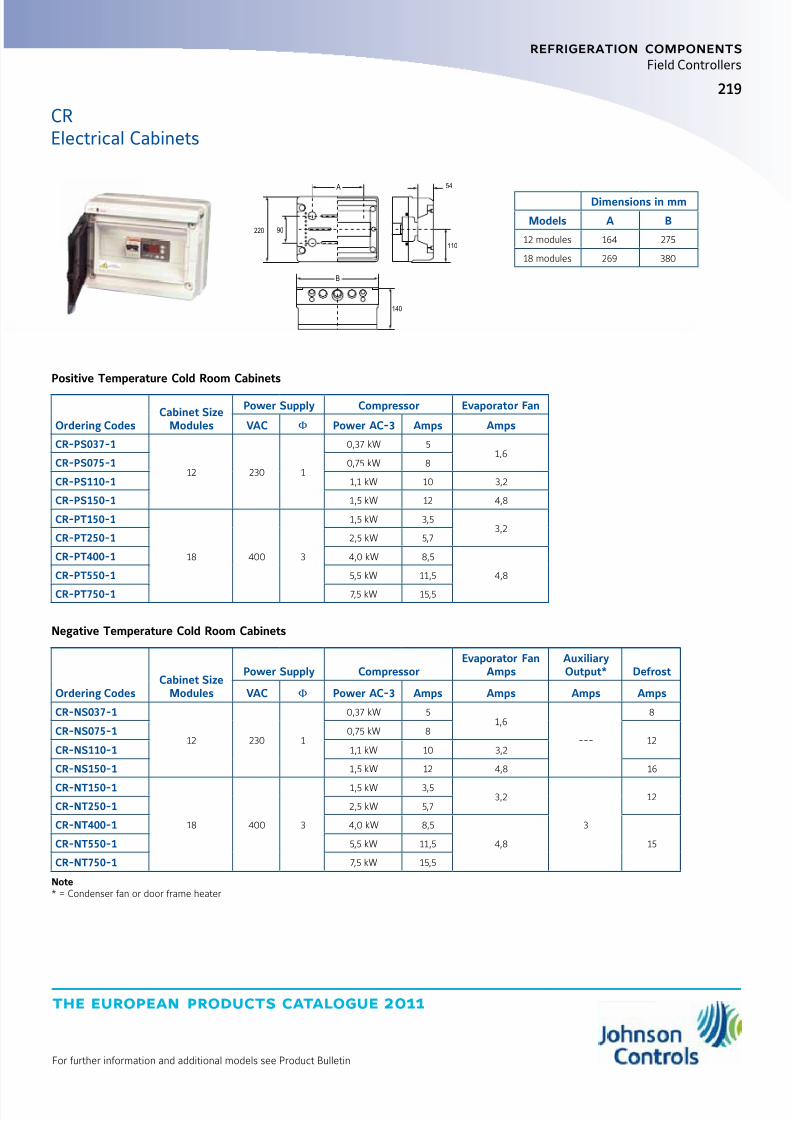
8/6/2019 Publ-6576 Prod Cat 11
http://slidepdf.com/reader/full/publ-6576-prod-cat-11 227/298
the european products catalogue 2011
For further information and additional models see Product Bulletin
219
refrigeration components
Field Controllers
CRElectrical Cabinets
Negative Temperature Cold Room Cabinets
Ordering CodesCabinet Size
Modules
Power Supply CompressorEvaporator Fan
AmpsAuxiliaryOutput* Defrost
VAC Φ Power AC-3 Amps Amps Amps Amps
CR-NS037-1
12 230 1
0,37 kW 51,6
---
8
CR-NS075-1 0,75 kW 812
CR-NS110-1 1,1 kW 10 3,2
CR-NS150-1 1,5 kW 12 4,8 16
CR-NT150-1
18 400 3
1,5 kW 3,53,2
3
12CR-NT250-1 2,5 kW 5,7
CR-NT400-1 4,0 kW 8,5
4,8 15CR-NT550-1 5,5 kW 11,5
CR-NT750-1 7,5 kW 15,5
Note* = Condenser fan or door frame heater
Dimensions in mm
Models A B
12 modules 164 275
18 modules 269 380
110
140
90220
54
B
A
Positive Temperature Cold Room Cabinets
Ordering CodesCabinet Size
Modules
Power Supply Compressor Evaporator Fan
VAC Φ Power AC-3 Amps Amps
CR-PS037-1
12 230 1
0,37 kW 51,6
CR-PS075-1 0,75 kW 8
CR-PS110-1 1,1 kW 10 3,2
CR-PS150-1 1,5 kW 12 4,8
CR-PT150-1
18 400 3
1,5 kW 3,53,2
CR-PT250-1 2,5 kW 5,7
CR-PT400-1 4,0 kW 8,5
4,8CR-PT550-1 5,5 kW 11,5
CR-PT750-1 7,5 kW 15,5
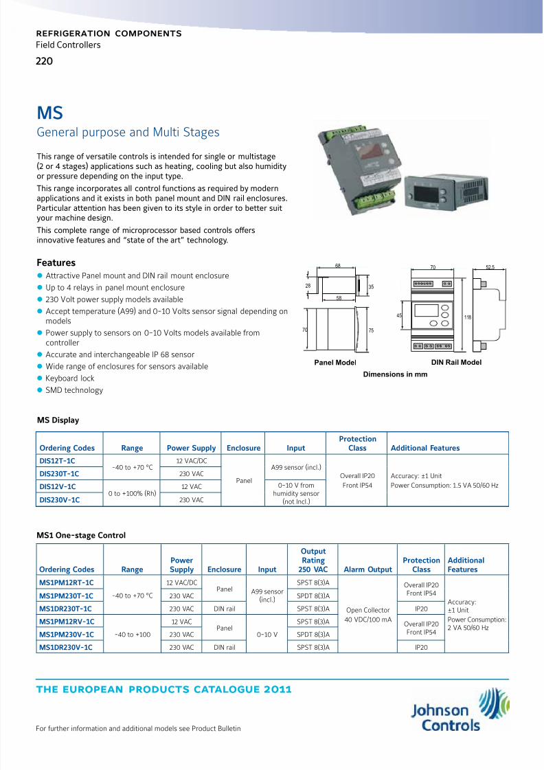
8/6/2019 Publ-6576 Prod Cat 11
http://slidepdf.com/reader/full/publ-6576-prod-cat-11 228/298
the european products catalogue 2011
For further information and additional models see Product Bulletin
220
refrigeration components
Field Controllers
General purpose and Multi Stages
MS
MS Display
Ordering Codes Range Power Supply Enclosure InputProtection
Class Additional Features
DIS12T-1C-40 to +70 °C
12 VAC/DC
Panel
A99 sensor (incl.)Overall IP20
Front IP54
Accuracy: ±1 Unit
Power Consumption: 1.5 VA 50/60 Hz
DIS230T-1C 230 VAC
DIS12V-1C0 to +100% (Rh)
12 VAC 0-10 V fromhumidity sensor
(not Incl.)DIS230V-1C 230 VAC
DIN Rail Model
68
28 35
58
70 75
Panel Model
11845
52.570
This range of versatile controls is intended for single or multistage(2 or 4 stages) applications such as heating, cooling but also humidityor pressure depending on the input type.
This range incorporates all control functions as required by modernapplications and it exists in both panel mount and DIN rail enclosures.Particular attention has been given to its style in order to better suityour machine design.
This complete range of microprocessor based controls offersinnovative features and “state of the art” technology.
Features z Attractive Panel mount and DIN rail mount enclosure
z Up to 4 relays in panel mount enclosure
z 230 Volt power supply models available
z Accept temperature (A99) and 0-10 Volts sensor signal depending onmodels
z Power supply to sensors on 0-10 Volts models available fromcontroller
z Accurate and interchangeable IP 68 sensor
z Wide range of enclosures for sensors available
z Keyboard lock
z SMD technology
MS1 One-stage Control
Ordering Codes RangePowerSupply Enclosure Input
OutputRating
250 VAC Alarm OutputProtection
ClassAdditionalFeatures
MS1PM12RT-1C
-40 to +70 °C
12 VAC/DCPanel A99 sensor
(incl.)
SPST 8(3)A
Open Collector
40 VDC/100 mA
Overall IP20Front IP54
Accuracy:±1 Unit
Power Consumption:2 VA 50/60 Hz
MS1PM230T-1C 230 VAC SPDT 8(3)A
MS1DR230T-1C 230 VAC DIN rail SPST 8(3)A IP20
MS1PM12RV-1C
-40 to +100
12 VACPanel
0-10 V
SPST 8(3)A Overall IP20Front IP54MS1PM230V-1C 230 VAC SPDT 8(3)A
MS1DR230V-1C 230 VAC DIN rail SPST 8(3)A IP20
Dimensions in mm

8/6/2019 Publ-6576 Prod Cat 11
http://slidepdf.com/reader/full/publ-6576-prod-cat-11 229/298
the european products catalogue 2011
For further information and additional models see Product Bulletin
221
refrigeration components
Field Controllers
MS2 Two-stage Control
Ordering Codes RangePowerSupply Enclosure Input
Output Rating250 VAC
ProtectionClass
AdditionalFeaturesEach Stage (1-2)
MS2PM12RT-1C
-40 to +70 °C
12 VAC/DC PanelA99
sensor(incl.)
SPST 8(3)AOverall IP20Front IP54
Accuracy:±1 °C
Power Consumption:2 VA 50/60 Hz
MS2DR230T-1C 230 VAC
DIN rail
SPST 8(3)A
IP20MS2DR48DT-1C
12-24 VAC/DC48 VDC
SPDT 8(3)A
MS2PM12RV-1C-40 to +100
12 VAC Panel0-10 V
SPST 8(3)AOverall IP20Front IP54
MS2DR230V-1C 230 VAC DIN rail SPST 8(3)A IP20
MS4 Four-stage Control
Ordering Codes RangePowerSupply Enclosure Input
Output Rating250 VAC
ProtectionClass
AdditionalFeatures
Each Stage(1 to 4)
MS4PM12RT-1C
-40 to +70 °C
12 VAC/DC Panel
A99sensor(incl.)
SPST 8(3)AOverall IP20Front IP54
Accuracy:±1 Unit
Power Consumption:2 VA 50/60 Hz
MS4DR230T-1C 230 VAC DIN rail SPST 8(3)A
MS4DR48T-1C12-24 VAC/DC
48 VDCPanel SPDT 8(3)A IP20
MSGeneral purpose and Multi Stages
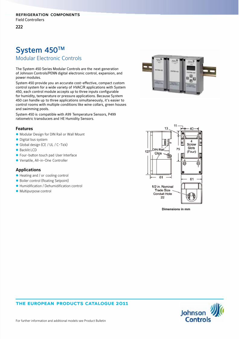
8/6/2019 Publ-6576 Prod Cat 11
http://slidepdf.com/reader/full/publ-6576-prod-cat-11 230/298
the european products catalogue 2011
For further information and additional models see Product Bulletin
222
refrigeration components
Field Controllers
Modular Electronic Controls
System 450TM
The System 450 Series Modular Controls are the next generationof Johnson Controls/PENN digital electronic control, expansion, andpower modules.
System 450 provide you an accurate cost-effective, compact customcontrol system for a wide variety of HVAC/R applications with System450, each control module accepts up to three inputs configurablefor humidity, temperature or pressure applications. Because System450 can handle up to three applications simultaneously, it’s easier tocontrol rooms with multiple conditions like wine collars, green housesand swimming pools.
System 450 is compatible with A99 Temperature Sensors, P499
ratiometric transducers and HE Humidity Sensors.
Features z Modular Design for DIN Rail or Wall Mount
z Digital bus system
z Global design (CE / UL / C-Tick)
z Backlit LCD
z Four-button touch pad User Interface
z Versatile, All-in-One Controller
Applications z Heating and / or cooling control
z Boiler control (floating Setpoint)
z Humidification / Dehumidification control
z Multipurpose control
Dimensions in mm
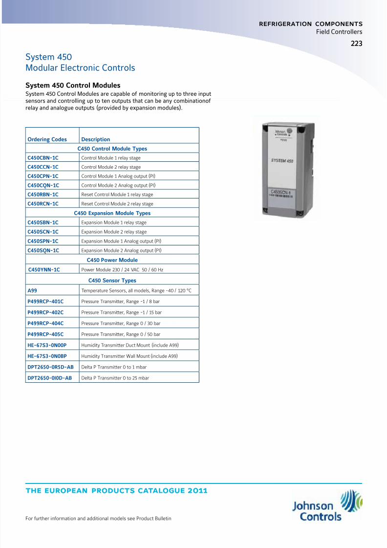
8/6/2019 Publ-6576 Prod Cat 11
http://slidepdf.com/reader/full/publ-6576-prod-cat-11 231/298
the european products catalogue 2011
For further information and additional models see Product Bulletin
223
refrigeration components
Field Controllers
Ordering Codes Description
C450 Control Module Types
C450CBN-1C Control Module 1 relay stage
C450CCN-1C Control Module 2 relay stage
C450CPN-1C Control Module 1 Analog output (PI)
C450CQN-1C Control Module 2 Analog output (PI)
C450RBN-1C Reset Control Module 1 relay stage
C450RCN-1C Reset Control Module 2 relay stage
C450 Expansion Module Types
C450SBN-1C Expansion Module 1 relay stage
C450SCN-1C Expansion Module 2 relay stage
C450SPN-1C Expansion Module 1 Analog output (PI)
C450SQN-1C Expansion Module 2 Analog output (PI)
C450 Power Module
C450YNN-1C Power Module 230 / 24 VAC 50 / 60 Hz
C450 Sensor Types
A99 Temperature Sensors, all models, Range -40 / 120 °C
P499RCP-401C Pressure Transmitter, Range -1 / 8 bar
P499RCP-402C Pressure Transmitter, Range -1 / 15 bar
P499RCP-404C Pressure Transmitter, Range 0 / 30 bar
P499RCP-405C Pressure Transmitter, Range 0 / 50 bar
HE-67S3-0N00P Humidity Transmitter Duct Mount (include A99)
HE-67S3-0N0BP Humidity Transmitter Wall Mount (include A99)
DPT2650-0R5D-AB Delta P Transmitter 0 to 1 mbar
DPT2650-0I0D-AB Delta P Transmitter 0 to 25 mbar
System 450Modular Electronic Controls
System 450 Control Modules
System 450 Control Modules are capable of monitoring up to three inputsensors and controlling up to ten outputs that can be any combinationof relay and analogue outputs (provided by expansion modules).

8/6/2019 Publ-6576 Prod Cat 11
http://slidepdf.com/reader/full/publ-6576-prod-cat-11 232/298

8/6/2019 Publ-6576 Prod Cat 11
http://slidepdf.com/reader/full/publ-6576-prod-cat-11 233/298

8/6/2019 Publ-6576 Prod Cat 11
http://slidepdf.com/reader/full/publ-6576-prod-cat-11 234/298

8/6/2019 Publ-6576 Prod Cat 11
http://slidepdf.com/reader/full/publ-6576-prod-cat-11 235/298
the european products catalogue 2011
For further information and additional models see Product Bulletin
227
refrigeration components
Condenser Fan Speed Controllers
The P215LR is a single pressure input fan speed controller for aircooled condensers with respectively single, dual and triple refrigerantcircuits. The controller varies the fan speed by directly sensing thepressure changes of one, two or three separate refrigerant circuits.The setpoint of each pressure transducer can be separately adjusted.The controller selects the input with the greatest cooling demand tocontrol the fan speed.
The controllers can be used in non corrosive refrigerant systems andvary the supply voltage to the motor from 45% to ≥95% of the suppliedvoltage using the phase cutting principle. It is recommended to confirmwith the electric motor manufacturer if a controller using the phasecutting principle for speed variation can be used. If the pressure dropsbelow the adjusted setpoint minus the proportional band, the output tothe motor is zero volt or the adjusted min. speed setting.
Features z Condenser pressure control by fan speed variation
z Pressure input
z Model with heatpump input available
z Transducers with proven reliability
z Easy accessible setpoint screw
z Adjustable minimum speed or cut-off selection(only on LR)
z Motor speed action can be reversed by interchanging only two wires
z Small dimensions
z DIN rail mounted
P215Pressure Actuated Single Phase Controller
Dimensions in mm
12
5370
32
45 83118
Ordering CodesRange(bar)
Prop. band(bar)
Setpoint(bar)
PressureConnection
SupplyVoltage50/60 Hz Rating
Additional Features
Note: Style 50 is allowedon the Dutch market!
P215LR -9110 14 to 24 4 1690 cm cap. / 50
230 VAC 3 Amp
Minimum speed adjustable
Single pressure input
P215LR -9111 8 to 14 2.5 10
P215LR -9130* Bulk pack version of type P215LR-9110 (15 pcs)
P215LR -921014 to 24 4 16
direct mount / 47
P215LR -9610
direct mount / 51P215LR -9611 8 to 14 2.5 10
P215LR -9114 22 to 42 6 30
90 cm cap. / 50
For R410A applications
P215LR -914014 to 24 4 16
230 V heatpump input
P215LR -9120 400 V version

8/6/2019 Publ-6576 Prod Cat 11
http://slidepdf.com/reader/full/publ-6576-prod-cat-11 236/298
the european products catalogue 2011
For further information and additional models see Product Bulletin
228
refrigeration components
Condenser Fan Speed Controllers
The P266 Pressure Actuated Single Phase Digital Controller is acost-effective, weather-resistant, durable motor speed control.The P266 control is designed for approved single-phase, PermanentSplit-Capacitor (PSC) motors commonly used in a wide variety of refrigeration and air conditioning condenser fan applications.
The P266 Series controls are designed to replace the Johnson Controls® P66 Series and P215 Series fan speed controls, providing additionalfeatures and flexibility, greater energy efficiency, and longer motor lifein a compact, rugged, weather-resistant package.
P266 models are available for 208 to 240 VAC and 440 to 575 VACrange applications. P266 controls have current ratings from 4 to 12 A
depending on the voltage and model.Some P266 models provide optional control of up to three auxiliary(fixed-speed) fans or fan stages. Also, some models provide twoadditional high-voltage triacs, which allow you to split the source powerto the main and auxiliary windings, and connect a low-speed capacitorto increase efficiency at low speed operation.
Features z Global design CE / UL / CSA / C-tick
z Microprocessor based
z Field Programmable, Digital setting
z One or two Electronic Pressure Transducers (P266SNR)
z Pressure range 0 - 35 bar or 0 - 52 bar z Patented design
z Output 8 or 12 Amp at 60°C ambient temperature
z Robust aluminium IP54 enclosure with integral heatsink
z Multi triac control providing energy savings up to 25%
z Optional auxiliary (vernier) control
z Auto selection 50 / 60 Hz
Dimensions in mm
P266
Pressure Actuated Single Phase Digital Controller
165
178
76
66

8/6/2019 Publ-6576 Prod Cat 11
http://slidepdf.com/reader/full/publ-6576-prod-cat-11 237/298
the european products catalogue 2011
For further information and additional models see Product Bulletin
229
refrigeration components
Condenser Fan Speed Controllers
P266Pressure Actuated Single Phase Digital Controller
Ordering Codes Description
Transducer Model
Included in Kit
Voltage Range
(in VAC)
Maximum Output
(Ampères)
High VAC
Triacs
Available Auxiliary
Fan Control CircuitsP266ABA-1K* P266 Fan Speed Control
with one P266 PressureTransducer and one 2 mcable
P266SNR-1C0-35 bar (0-508 psi)
208 to 240 8 3
3
P266ABA-3K*P266SNR-2C
0-52 bar (0-754 psi)
P266ABA-2K* P266 Fan Speed Controlwith two P266 PressureTransducer and one 2 mcable
P266SNR-1C0-35 bar (0-508 psi)
P266ABA-4K*P266SNR-2C
0-52 bar (0-754 psi)
P266BHA-1K* P266 Fan Speed Controlwith one P266 PressureTransducer and one 2 mcable
P266SNR-1C0-35 bar (0-508 psi)
440 to 575 4 2P266BHA-3K*
P266SNR-2C0-52 bar (0-754 psi)
P266BHA-2K* P266 Fan Speed Controlwith two P266 Pressure
Transducer and one 2 mcable
P266SNR-1C0-35 bar (0-508 psi)
P266BHA-4K* P266SNR-2C0-52 bar (0-754 psi)
P266EAA-1K*
P266 Fan Speed Controlwith Internal Transformerand one P266 PressureTransducer and one 2 mcable
P266SNR-1C0-35 bar (0-508 psi)
208 to 240
8
3
---
P266EAA-3K*P266SNR-2C
0-52 bar (0-754 psi)
P266EBA-1K*P266SNR-1C
0-35 bar (0-508 psi)3
P266EBA-3K*P266SNR-2C
0-52 bar (0-754 psi)
P266ECA-1K*P266SNR-1C
0-35 bar (0-508 psi)
1
---
P266ECA-3KP266SNR-2C
0-52 bar (0-754 psi)
P266EDA-1K* P266SNR-1C0-35 bar (0-508 psi)3
P266EDA-3K*P266SNR-2C
0-52 bar (0-754 psi)
P266EEA-1K*P266SNR-1C
0-35 bar (0-508 psi)12
---
P266EFA-3K*P266SNR-2C
0-52 bar (0-754 psi)3
Note:Factory default settings: Start Voltage is set to 40% of the supply line-voltage. End Voltage is set to 95% of the supply line-voltage.Start Pressure is set to 44% of the P266 transducer’s total pressure range. End Pressure is set to 51% of the P266 transducer’s total pressure range.
P266SNR Electronic Pressure Transducers
Ordering Codes Description
P266SNR-1C Electronic Pressure Transducer: 0 to 35 bar total range with a 1/4 in. SAE Female Flare connection and a 2 meter cable.
P266SNR-2C Electronic Pressure Transducer: 0 to 52 bar total range with a 1/4 in. SAE Female Flare connection and a 2 meter cable.

8/6/2019 Publ-6576 Prod Cat 11
http://slidepdf.com/reader/full/publ-6576-prod-cat-11 238/298
the european products catalogue 2011
For further information and additional models see Product Bulletin
230
refrigeration components
Condenser Fan Speed Controllers
These controllers are designed for speed variation of 3-phase motors,especially for fan speed control on air cooled condensers.
Head pressure control of a refrigeration system, through speedvariation of the fan, results in optimum performance throughout theyear.
Using a pressure transducer as the input device, gives the most directand fastest response to pressure variations in the refrigerant system.The controller varies the supply voltage to the motor from 30% to atleast 96% over the proportional band using the phase cutting principle.It is recommended to confirm with the electric motor manufacturer if acontroller using the phase cutting principle for speed variation can be
used. Motors that will be controlled by the P255 should not draw morethan 5 A per phase.
The controller used for dual pressure input varies the fan speed bydirectly sensing the pressure changes of two separate refrigerantcircuits. Each pressure transducer can be adjusted at a setpointbetween 8 to 42 bar.The controller selects the input with the greatest cooling demand.The transducers can be used in non-corrosive refrigerant systems.
Features z Condenser pressure control by fan speed variation
z Pressure input
z Dual input possibility
z Transducers with proven reliability
z Easy accessible setpoint screw
z Minimum speed or cut-off selection
z Adjustable minimum speed or cut-off
z Adjustable maximum speed limit
z Proportional band adjustment
z Contact input to force output to max. or off
z Allows connection in both “Star” and “Delta” configurations
z Motor speed action can be reversed by interchanging only two wires
z Adjustable hysteresis in cut-off mode
z IP54 enclosure for electronic module
z Cosφ motor adjustment
Dimensions in mm
213
205 180
125
56
107
P255
Single/Dual Input Pressure Actuated 3-phase Controller

8/6/2019 Publ-6576 Prod Cat 11
http://slidepdf.com/reader/full/publ-6576-prod-cat-11 239/298
the european products catalogue 2011
For further information and additional models see Product Bulletin
231
refrigeration components
Condenser Fan Speed Controllers
Ordering Codes Range(bar) Prop. band(bar) PressureConnection
Supply Voltage
(VAC) 50/60Hz 3 phase Rating Full Volagesetpoint Additional Features
P255ML -9200
14 to 24 1 to 6
Style 47 230
5 Amp
16
Direct mount sensor
P255MM -9100 Style 45A
400
---
P255MM -9200Style 47 Direct mount sensor
P255MM -9201 8 to 14 0.5 to 4 10
P255MM -960014 to 24 1 to 6
Style 1316
---
P255MM -9500
Style 50
Same as P255MM-9100 but Style 50
P255MM -9501 8 to 140.5 to 4
10 Same as P255MM-9101 but Style 50
P255MM -9502 3.5 to 10 6 ---
P255MM -9503 22 to 42 1 to 8 30 For use on R410A applications
P255Single/Dual Input Pressure Actuated 3-phase Controller

8/6/2019 Publ-6576 Prod Cat 11
http://slidepdf.com/reader/full/publ-6576-prod-cat-11 240/298
the european products catalogue 2011
For further information and additional models see Product Bulletin
232
refrigeration components
Condenser Fan Speed Controllers
Replacement Press. transducers for P215 versions (300K ohm)
Ordering Codes Range Setting (bar) StyleCap. Length
(m)
Additional Features
Note: Style 50 is allowed on the Dutch market!
P35AC -910014/24 16
45A
0.9
---P35AC -920247
P35AC -9203 8/14 10
P35AC -9500 14/24 1650
Same as P35AC-9100 but Style 50
P35AC -9501 8/14 10 Same as P35AC-9101 but Style 50
P35AC -9512 22/42 30 50 For R410A applications
P35AC -9600 14/24 16 13 (also used for replacement P15/P215 series fan speed controllers)
Dimensions in mm
85
6
26
37
67
19
Replacement Press. transducers P255 versions (100K ohm)
Ordering Codes Range Setting (bar) StyleCap. Length
(m)
Additional Features
Note: Style 50 is allowed on the Dutch market!
P35AC -9200 14/24 1647
0.9
---P35AC -9201 8/14 10
P35AC -9106 14/2416
45A
P35AC -9604 14/24 13
P35AC -9505 8/14 10
50
Same as P35AC-9105 but Style 50
P35AC -9506 14/24 16 Same as P35AC-9106 but Style 50
P35AC -9511 22/42 30 For R410A applications
Replacement Press. transducers P255 versions (500K ohm)
Ordering Codes Range Setting (bar) StyleCap. Length
(m)
Additional Features
Note: Style 50 is allowed on the Dutch market!
P35AC-9510 14/24 1650 0.9
Special 500 KOhm for P215LR-400V. version
P35AC-9513 22/40 30 Special 500 KOhm version for R410A applications
P35
Mechanical Pressure Transducers

8/6/2019 Publ-6576 Prod Cat 11
http://slidepdf.com/reader/full/publ-6576-prod-cat-11 241/298
the european products catalogue 2011
For further information and additional models see Product Bulletin
233233
refrigeration components
Condenser Fan Speed Controllers
Ordering Codes Description
BKT034N602R Mounting bracket + screws for P35AC transducer
Replacement Parts
P38AA-9111 Replacement electronic module P215LR-230 V types
P38AA-9112 Replacement electronic module P215LR-230 V incl. heatpump input types
P38AA-9211 Replacement electronic module P215BR-230 V types
P38AA-9311 Replacement electronic module P215TR-230 V types
P38AD-9100 Replacement electronic module P255MM
P38AD-9101 Replacement electronic module P255ML
Accessories
for Pressure Transducers
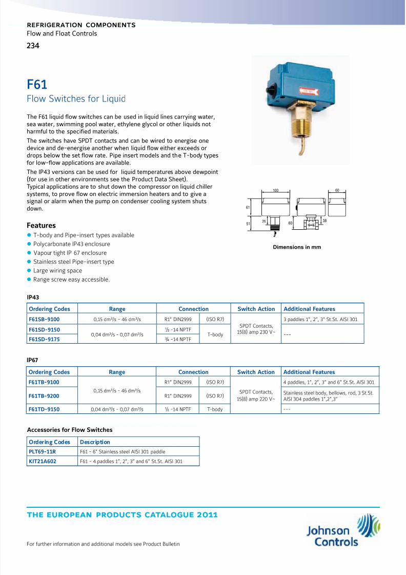
8/6/2019 Publ-6576 Prod Cat 11
http://slidepdf.com/reader/full/publ-6576-prod-cat-11 242/298
the european products catalogue 2011
For further information and additional models see Product Bulletin
234
refrigeration components
Flow and Float Controls
The F61 liquid flow switches can be used in liquid lines carrying water,sea water, swimming pool water, ethylene glycol or other liquids notharmful to the specified materials.
The switches have SPDT contacts and can be wired to energise onedevice and de-energise another when liquid flow either exceeds ordrops below the set flow rate. Pipe insert models and the T-body typesfor low-flow applications are available.
The IP43 versions can be used for liquid temperatures above dewpoint(for use in other environments see the Product Data Sheet).Typical applications are to shut down the compressor on liquid chillersystems, to prove flow on electric immersion heaters and to give a
signal or alarm when the pump on condenser cooling system shutsdown.
Features z T-body and Pipe-insert types available
z Polycarbonate IP43 enclosure
z Vapour tight IP 67 enclosure
z Stainless steel Pipe-insert type
z Large wiring space
z Range screw easy accessible.
IP43
Ordering Codes Range Connection Switch Action Additional Features
F61SB-9100 0,15 dm³/s - 46 dm³/s R1” DIN2999 (ISO R7)SPDT Contacts,
15(8) amp 230 V~
3 paddles 1”, 2”, 3” St.St. AISI 301
F61SD-91500,04 dm³/s - 0,07 dm³/s
½ -14 NPTFT-body ---
F61SD-9175 ¾ -14 NPTF
Dimensions in mm
6038
100 60
51
61
29
IP67
Ordering Codes Range Connection Switch Action Additional Features
F61TB-9100
0,15 dm³/s - 46 dm³/s
R1” DIN2999 (ISO R7)
SPDT Contacts,
15(8) amp 220 V~
4 paddles, 1”, 2”, 3” and 6” St.St. AISI 301
F61TB-9200 R1” DIN2999 (ISO R7)Stainless steel body, bellows, rod, 3 St.St.AISI 304 paddles 1”,2”,3”
F61TD-9150 0,04 dm³/s - 0,07 dm³/s ½ -14 NPTF T-body ---
Accessories for Flow Switches
Ordering Codes Description
PLT69-11R F61 - 6” Stainless steel AISI 301 paddle
KIT21A602 F61 - 4 paddles 1”, 2”, 3” and 6” St.St. AISI 301
F61
Flow Switches for Liquid
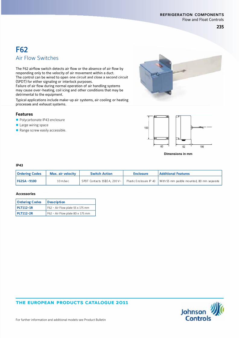
8/6/2019 Publ-6576 Prod Cat 11
http://slidepdf.com/reader/full/publ-6576-prod-cat-11 243/298
the european products catalogue 2011
For further information and additional models see Product Bulletin
235235
refrigeration components
Flow and Float Controls
IP43
Ordering Codes Max. air velocity Switch Action Enclosure Additional Features
F62SA –9100 10 m/sec SPDT Contacts 15(8) A, 230 V~ Plastic Enclosure IP 43 With 55 mm paddle mounted, 80 mm separate
Dimensions in mm
Accessories
Ordering Codes Description
PLT112-1R F62 - Air Flow plate 55 x 175 mm
PLT112-2R F62 - Air Flow plate 80 x 175 mm
100
60 62 196
The F62 airflow switch detects air flow or the absence of air flow byresponding only to the velocity of air movement within a duct.The control can be wired to open one circuit and close a second circuit(SPDT) for either signaling or interlock purposes.Failure of air flow during normal operation of air handling systemsmay cause over-heating, coil icing and other conditions that may bedetrimental to the equipment.
Typical applications include make-up air systems, air cooling or heatingprocesses and exhaust systems.
Features z Polycarbonate IP43 enclosure z Large wiring space
z Range screw easily accessible.
F62
Air Flow Switches
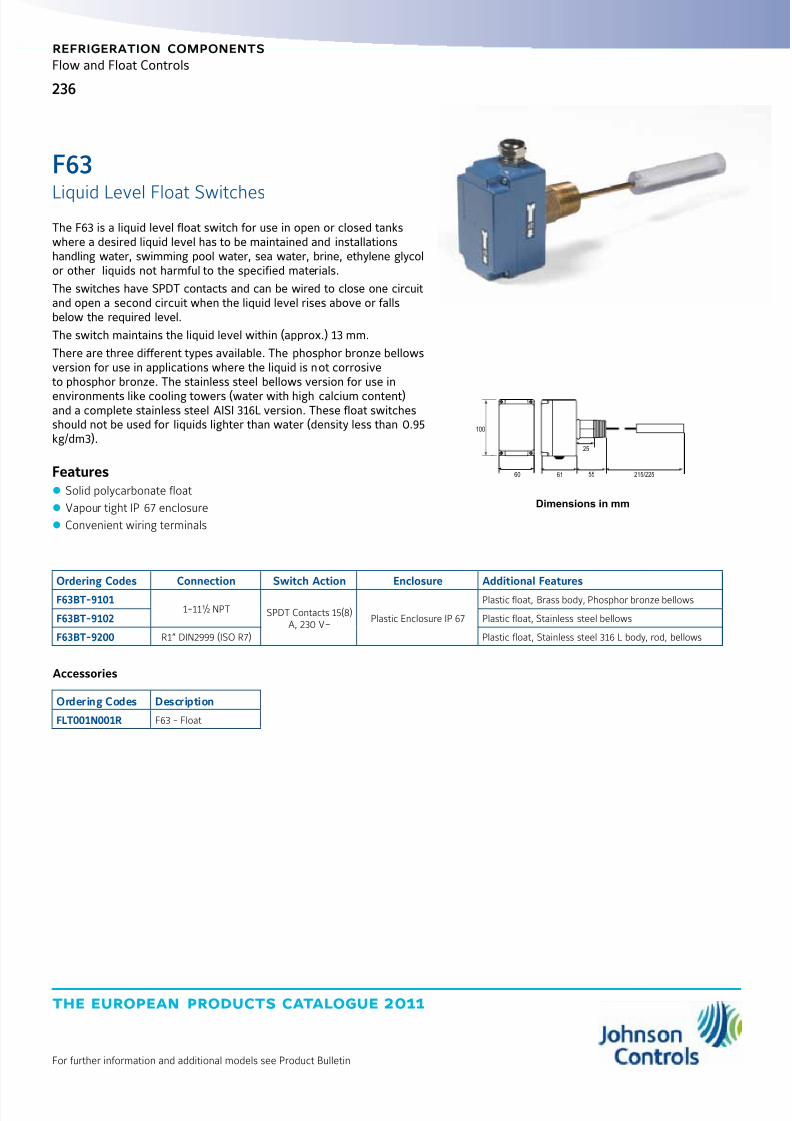
8/6/2019 Publ-6576 Prod Cat 11
http://slidepdf.com/reader/full/publ-6576-prod-cat-11 244/298
the european products catalogue 2011
For further information and additional models see Product Bulletin
236
refrigeration components
Flow and Float Controls
The F63 is a liquid level float switch for use in open or closed tankswhere a desired liquid level has to be maintained and installationshandling water, swimming pool water, sea water, brine, ethylene glycolor other liquids not harmful to the specified materials.
The switches have SPDT contacts and can be wired to close one circuitand open a second circuit when the liquid level rises above or fallsbelow the required level.
The switch maintains the liquid level within (approx.) 13 mm.
There are three different types available. The phosphor bronze bellowsversion for use in applications where the liquid is not corrosiveto phosphor bronze. The stainless steel bellows version for use in
environments like cooling towers (water with high calcium content)and a complete stainless steel AISI 316L version. These float switchesshould not be used for liquids lighter than water (density less than 0.95kg/dm3).
Features z Solid polycarbonate float
z Vapour tight IP 67 enclosure
z Convenient wiring terminals
Ordering Codes Connection Switch Action Enclosure Additional Features
F63BT-91011-11½ NPT SPDT Contacts 15(8)
A, 230 V~Plastic Enclosure IP 67
Plastic float, Brass body, Phosphor bronze bellows
F63BT-9102 Plastic float, Stainless steel bellows
F63BT-9200 R1” DIN2999 (ISO R7) Plastic float, Stainless steel 316 L body, rod, bellows
Dimensions in mm
100
60 61
25
55 215/225
Accessories
Ordering Codes Description
FLT001N001R F63 - Float
F63
Liquid Level Float Switches

8/6/2019 Publ-6576 Prod Cat 11
http://slidepdf.com/reader/full/publ-6576-prod-cat-11 245/298

8/6/2019 Publ-6576 Prod Cat 11
http://slidepdf.com/reader/full/publ-6576-prod-cat-11 246/298
the european products catalogue 2011
For further information and additional models see Product Bulletin
238
refrigeration components
Pressure Controls
This switch senses a change in the (differential) pressure as the airflowchanges. The (differential) pressure is applied to the two sides of adiaphragm in the control.
The spring-loaded diaphragm moves and actuates the switch. Theseries P233A/F can also be used to detect small positive gaugepressure or to detect a vacuum.
Features z One switch to measure relative pressure, vacuum or differentialpressure
z
Various accessories available z Compact and durable construction
z Easy mounting and wiring, various mounting possibilities
z Standard PG 11 nipple and optional DIN 43650 connector
z Accurate and stable switch point
z SPDT contact standard
Application z This (differential) pressure switch is used to sense flow of air, single ordifferential air pressure
Typical applications include:
z Detect clogged filter
z Detect frost or ice build-up on air conditioning coils
z Air proving in heating or ventilation ducts
z Maximum airflow controller for variable air volume system
z Detect blocked flue or vent
z Monitor fan operation
Dimensions in mm
72 60 62
60 46
5272
o 4 mm
Use M4 screws max.length 12 mm
P233
Sensitive Differential

8/6/2019 Publ-6576 Prod Cat 11
http://slidepdf.com/reader/full/publ-6576-prod-cat-11 247/298
the european products catalogue 2011
For further information and additional models see Product Bulletin
239
refrigeration components
Pressure Controls
Ordering Codes Switch pointRange (mbar)
Switching
Differential(mbar) ** Contacts Pack Additional Features
P233F-P3-AAC 0,3 fixed
< 0.3
SPDT contacts,
Contact rating5(2) A 250 VAC
ind.---
P233A-4-AAC
0,5 to 4
---
P233A-4-AAD* bulk ---
P233A-4-AHC ind. GMT008N600R + BKT024N001R
P233A-4-PAD*
50 to 400 Pa
bulk Scale in Pa
P233A-4-PAC
ind.
---
P233A-4-PHC Scale in Pa, GMT008N600R + BKT024N001R
P233A-4-PKC Scale in Pa, FTG015N602R (2x) + 2 m tube 4/7 mm
P233A-4-AKC 0,5 to 4 FTG015N602R (2x) + 2 m tube 4/7 mm
P233A-6-AAC 0,5 to 6 ind. ---P233A-6-AAD* bulk
P233A-10-AAC1,4 to 10
< 0.5
ind.
---
P233A-10-AHC GMT008N600R + BKT024N001R
P233A-10-PAC140 to 1000 Pa
---
P233A-10-PKC Scale in Pa, FTG015N602R (2x) + 2 m tube 4/7 mm
P233A-10-AAD*1,4 to 10
bulk ---
P233-10-AKC
Ind.FTG015N602R (2x) + 2 m tube 4/7 mm
P233A-50-AAC 6 to 50 < 1
P233A-10-PHC 140 to 1000 Pa < 0,5 Scale in Pa, GMT008N600R + BKT024N001R
Notes
* : Quantity orders only** : Switching differential is maximum value mid-range
P233Sensitive Differential

8/6/2019 Publ-6576 Prod Cat 11
http://slidepdf.com/reader/full/publ-6576-prod-cat-11 248/298
the european products catalogue 2011
For further information and additional models see Product Bulletin
240
refrigeration components
Pressure Controls
The P20 series high and low limit (cut-out) controls forall non-corrosive refrigerants are compact pressure controls ideallysuited for commercial or residential packaged air conditioning units,heat pumps, small water chillers, ice cube machines and otherapplications where a semi fixed setting is acceptable or required andwhere mounting space is limited.
The P20 series includes auto reset as well as manual reset models andis factory set.
A special setting tool is available while also field (screwdriver)adjustable models can be chosen.
Features z Field proven reliability
z Reset tab must be released before restart(Trip free manual reset)
z Compact design
z Enclosed dust-tight switch
z SPDT contact with special terminals
z Test pressure 53 bar
z Designed for at least 300000 cycles
Dimensions in mm
Style 13 Style 45AStyle 34 Style 50
26 17.5
37
67
19
85
56
Style 35
P20
for Air-conditioning and Heat pump Applications

8/6/2019 Publ-6576 Prod Cat 11
http://slidepdf.com/reader/full/publ-6576-prod-cat-11 249/298
the european products catalogue 2011
For further information and additional models see Product Bulletin
241
refrigeration components
Pressure Controls
Ordering Codes
Range
(bar)
Differential
fixed Set at (bar) Style Capillary Length Switch Action PED approvalP20EA-9610C
0.5 to 10
0.91.5
13
90 cm
SPDT, 8 A,
Open Low,
Auto Reset
---P20EA-9611D
2
120 cm
P20EA-9620D1.5
90 cm
P20EA-9621D 120 cm
P20EA-9160L
7 to 29
3.1 17 45A
90 cm
SPDT, 8 A,
Open High,
Auto ResetP20EA-9561K 1.2 16 50
P20EA-9670 5.2 28 13
P20for Air-conditioning and Heat pump Applications
P20 High Pressure Control
Ordering CodesRange(bar)
Differentialfixed
Set at(bar) Style
CapillaryLength Switch Action
AdditionalFeatures
PEDApproval
P20EA-9670X --- --- 18 13 90 cm
SPDT, 8 A, Open High,
Auto Reset---
P20EA-9681T
7 to 29
7.1 24 13 120 cm
P20EA-9950C 1.1 1034
90 cm
P20EA-9950K 1.2 16
P20GA-9650X
---
28
13SPDT, 8 A, Open High,
Manual ResetWrench adjustmentP20GA-9651N 19
P20GA-9650T 24
P20 Low and High Pressure Control Universal Replacements
Ordering CodesRange(bar)
Differentialfixed
Set at(bar) Style
CapillaryLength Switch Action
AdditionalFeatures
PEDApproval
P20EA-9530FC0.5 to 10
2.1 3 50
90 cm
SPDT, 8 A,
Auto Reset
Open Low ---P20EA-9630FC 2.1 3 13
P20EA-9570XC7 to 29
5.2 28 50
Open High
P20EA-9670XC 5.2 2813
P20EL-9670TC 14 to 42
6.5
37
P20FA-9510FC0.5 to 10 3
50
SPDT, 8 A,
Manual Reset
Open Low ---P20FA-9610FC 13
P20GA-9550XC 7 to 29 28 50
Open High P20GA-9650XC13
P20GL-9650TC 14 to 42 37
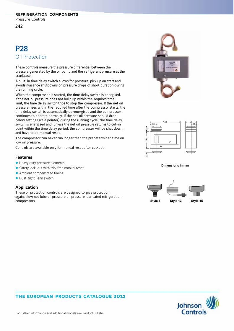
8/6/2019 Publ-6576 Prod Cat 11
http://slidepdf.com/reader/full/publ-6576-prod-cat-11 250/298
the european products catalogue 2011
For further information and additional models see Product Bulletin
242
refrigeration components
Pressure Controls
These controls measure the pressure differential between thepressure generated by the oil pump and the refrigerant pressure at thecrankcase.
A built-in time delay switch allows for pressure-pick up on start andavoids nuisance shutdowns on pressure drops of short duration duringthe running cycle.
When the compressor is started, the time delay switch is energised.If the net oil pressure does not build up within the required timelimit, the time delay switch trips to stop the compressor. If the net oilpressure rises within the required time after the compressor starts, thetime delay switch is automatically de-energised and the compressor
continues to operate normally. If the net oil pressure should dropbelow setting (scale pointer) during the running cycle, the time delayswitch is energised and, unless the net oil pressure returns to cut-inpoint within the time delay period, the compressor will be shut down,and have to be manual reset.
The compressor can never run longer than the predetermined time onlow oil pressure.
Controls are available only for manual reset after cut-out.
Features z Heavy duty pressure elements
z Safety lock-out with trip-free manual reset
z
Ambient compensated timing z Dust-tight Penn switch
ApplicationThese oil protection controls are designed to give protectionagainst low net lube oil pressure on pressure lubricated refrigerationcompressors.
Dimensions in mm
Style 5 Style 15Style 13
P28
Oil Protection
8/6/2019 Publ-6576 Prod Cat 11
http://slidepdf.com/reader/full/publ-6576-prod-cat-11 251/298
the european products catalogue 2011
For further information and additional models see Product Bulletin
243
refrigeration components
Pressure Controls
P28Oil Protection
Ordering Codes
Range
(bar) Style
Time
Delay (s) Voltage Switch Action Refrigerant Additional FeaturesP28DA-9341
0.6 to 4.8
5 50115/230
15(8) A, 230 VAC,Open Low,
Alarm and SafeLight Contacts
non-corr.
Incl. plastic PG nipple 13.5 + 2 flare nuts
P28DA-9660 13 90 ---
P28DJ-9360 5 90
230
IP 66 enclosure
P28DJ-9861 15 90 NH3IP 66 enclosure,Incl. 2 connectors CNR003N001
P28DP-9300
5
---
non-corr.
Without time delay
P28DP-9340 50 ---
P28DP-9360 90 ---
P28DP-9380120
---
P28DP-9381 Concealed adjustment, set 0.65 bar
P28DP-964013
50 ---P28DP-9660 90 ---
P28DP-9680 120 ---
P28DP-9840
15
50
NH3
---
P28DP-9860 --- 90 --- ---
P28DN-9750 --- 50 115/230 --- Concealed adjustment, set 1,5 bar
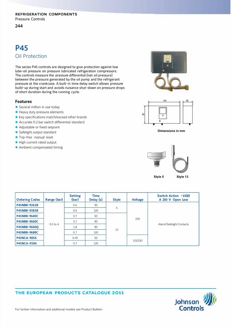
8/6/2019 Publ-6576 Prod Cat 11
http://slidepdf.com/reader/full/publ-6576-prod-cat-11 252/298
the european products catalogue 2011
For further information and additional models see Product Bulletin
244
refrigeration components
Pressure Controls
Style 5 Style 13
Dimensions in mm
Ordering Codes Range (bar)Setting(bar)
TimeDelay (s) Style Voltage
Switch Action ~15(8)A 230 V Open Low
P45NBB-9361B
0.5 to 4
0.6 905
230
Alarm/Safelight Contacts
P45NBB-9381B 0.6 120
P45NBB-9640C 0.7 50
13
P45NBB-9660C 0.7 90
P45NBB-9660Q 1.8 90
P45NBB-9680C 0.7 120
P45NCA-9056 0.45 50115/230
P45NCA-9104 0.7 120
The series P45 controls are designed to give protection against lowlube-oil pressure on pressure lubricated refrigeration compressors.The controls measure the pressure differential (net oil pressure)between the pressure generated by the oil pump and the refrigerantpressure at the crankcase. A built-in time delay switch allows pressurebuild-up during start and avoids nuisance shut-down on pressure dropsof short duration during the running cycle.
Features z Several million in use today
z Heavy duty pressure elements
z Key specifications match/exceed other brands
z Accurate 0.2 bar switch differential standard
z Adjustable or fixed setpoint
z Safelight output standard
z Trip-free manual reset
z High current rated output
z Ambient compensated timing
P45
Oil Protection
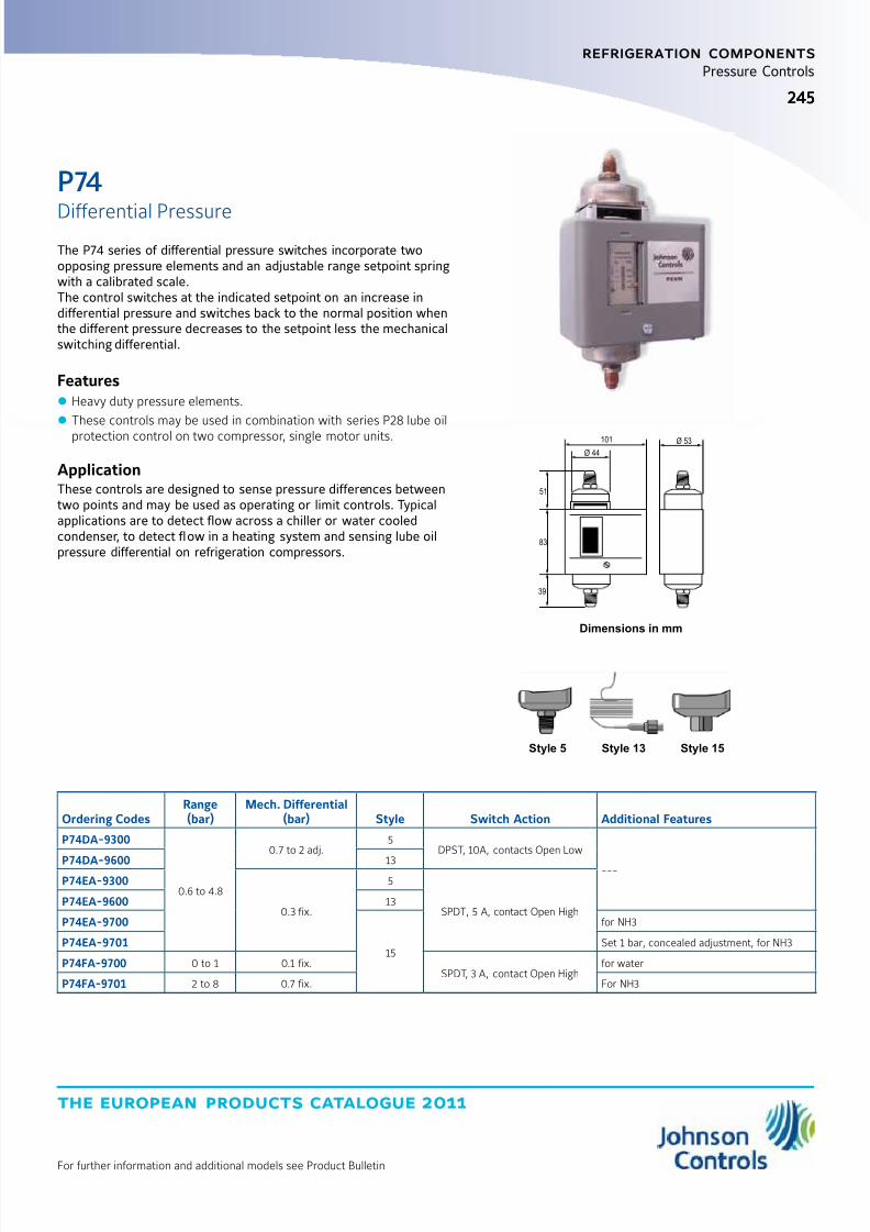
8/6/2019 Publ-6576 Prod Cat 11
http://slidepdf.com/reader/full/publ-6576-prod-cat-11 253/298
the european products catalogue 2011
For further information and additional models see Product Bulletin
245245
refrigeration components
Pressure Controls
Ordering CodesRange(bar)
Mech. Differential(bar) Style Switch Action Additional Features
P74DA-9300
0.6 to 4.8
0.7 to 2 adj.5
DPST, 10A, contacts Open Low
---P74DA-9600 13P74EA-9300
0.3 fix.
5
SPDT, 5 A, contact Open HighP74EA-9600 13
P74EA-9700
15
for NH3
P74EA-9701 Set 1 bar, concealed adjustment, for NH3
P74FA-9700 0 to 1 0.1 fix.SPDT, 3 A, contact Open High
for water
P74FA-9701 2 to 8 0.7 fix. For NH3
Dimensions in mm
83
39
51
101
Ø 44 Ø 53
The P74 series of differential pressure switches incorporate twoopposing pressure elements and an adjustable range setpoint springwith a calibrated scale.The control switches at the indicated setpoint on an increase indifferential pressure and switches back to the normal position whenthe different pressure decreases to the setpoint less the mechanicalswitching differential.
Features z Heavy duty pressure elements.
z These controls may be used in combination with series P28 lube oil
protection control on two compressor, single motor units.
ApplicationThese controls are designed to sense pressure differences betweentwo points and may be used as operating or limit controls. Typicalapplications are to detect flow across a chiller or water cooledcondenser, to detect flow in a heating system and sensing lube oilpressure differential on refrigeration compressors.
P74
Differential Pressure
Style 5 Style 15Style 13
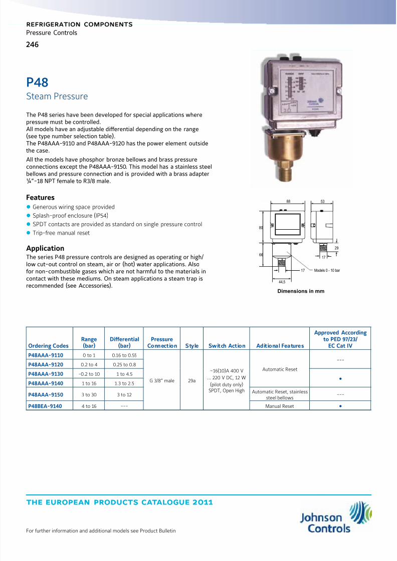
8/6/2019 Publ-6576 Prod Cat 11
http://slidepdf.com/reader/full/publ-6576-prod-cat-11 254/298
the european products catalogue 2011
For further information and additional models see Product Bulletin
246
refrigeration components
Pressure Controls
The P48 series have been developed for special applications wherepressure must be controlled.All models have an adjustable differential depending on the range(see type number selection table).The P48AAA-9110 and P48AAA-9120 has the power element outsidethe case.
All the models have phosphor bronze bellows and brass pressureconnections except the P48AAA-9150. This model has a stainless steelbellows and pressure connection and is provided with a brass adapter¼”-18 NPT female to R3/8 male.
Features z Generous wiring space provided
z Splash-proof enclosure (IP54)
z SPDT contacts are provided as standard on single pressure control
z Trip-free manual reset
ApplicationThe series P48 pressure controls are designed as operating or high/low cut-out control on steam, air or (hot) water applications. Alsofor non-combustible gases which are not harmful to the materials incontact with these mediums. On steam applications a steam trap isrecommended (see Accessories).
Dimensions in mm
Ordering CodesRange(bar)
Differential(bar)
PressureConnection Style Switch Action Aditional Features
Approved Accordingto PED 97/23/
EC Cat IV
P48AAA-9110 0 to 1 0.16 to 0.55
G 3/8” male 29a
~16(10)A 400 V
… 220 V DC, 12 W
(pilot duty only)
SPDT, Open High
Automatic Reset
---P48AAA-9120 0.2 to 4 0.25 to 0.8
P48AAA-9130 -0.2 to 10 1 to 4.5
P48AAA-9140 1 to 16 1.3 to 2.5
P48AAA-9150 3 to 30 3 to 12 Automatic Reset, stainlesssteel bellows ---
P48BEA-9140 4 to 16 --- Manual Reset
66
44,5
17
80
88 53
17
29
Models 0 - 10 bar
P48
Steam Pressure

8/6/2019 Publ-6576 Prod Cat 11
http://slidepdf.com/reader/full/publ-6576-prod-cat-11 255/298
the european products catalogue 2011
For further information and additional models see Product Bulletin
247247
refrigeration components
Pressure Controls
The P735 series pressure controls may be used for control functions orlimit functions, depending on model number. All models are providedwith alarm contacts. All standard models have phosphor bronzebellows and brass pressure connections. Models for use with ammoniaare provided with stainless steel bellows and connectors.
Features z Generous wiring space
z SPDT contacts are provided as standard on single pressure controls
z Trip-free manual reset
ApplicationThese pressure controls are designed for use in a variety of applications involving refrigeration high or low pressure. Modelssupplied have a “whole range” design, enabling them to be used withall non-corrosive refrigerants which are within the operating rangeof the control. They may also be used for other high or low pressureapplications such as air, water etc. Models which can be used withammonia are included in the program.
Dimensions in mm
70
13
92
42 28
19
25
11 51
112.5
55
2568
77
Style 5 Style 15Style 30Style 28
P735
Single Pressure
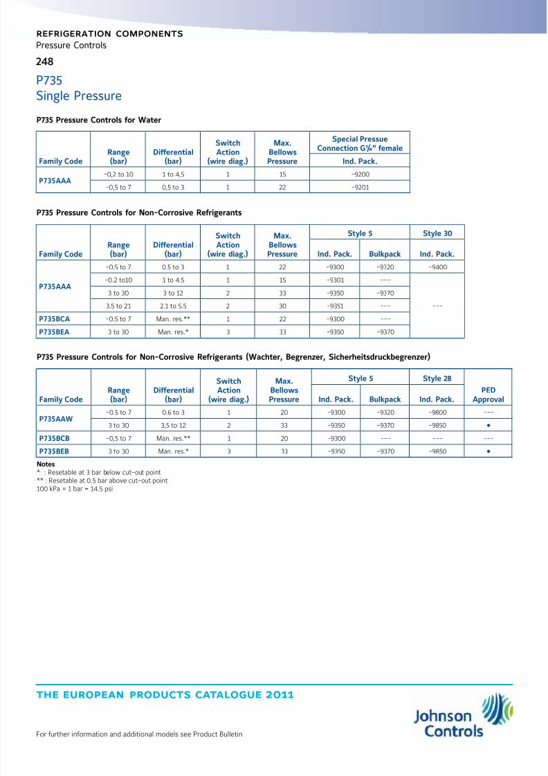
8/6/2019 Publ-6576 Prod Cat 11
http://slidepdf.com/reader/full/publ-6576-prod-cat-11 256/298
the european products catalogue 2011
For further information and additional models see Product Bulletin
248
refrigeration components
Pressure Controls
P735 Pressure Controls for Water
Family CodeRange(bar)
Differential(bar)
SwitchAction
(wire diag.)
Max.BellowsPressure
Special PressueConnection G¼” female
Ind. Pack.
P735AAA-0,2 to 10 1 to 4,5 1 15 -9200
-0,5 to 7 0,5 to 3 1 22 -9201
P735 Pressure Controls for Non-Corrosive Refrigerants
Family CodeRange(bar)
Differential(bar)
SwitchAction
(wire diag.)
Max.BellowsPressure
Style 5 Style 30
Ind. Pack. Bulkpack Ind. Pack.
P735AAA
-0.5 to 7 0.5 to 3 1 22 -9300 -9320 -9400
-0.2 to10 1 to 4.5 1 15 -9301 ---
---
3 to 30 3 to 12 2 33 -9350 -9370
3.5 to 21 2.1 to 5.5 2 30 -9351 ---
P735BCA -0.5 to 7 Man. res.** 1 22 -9300 ---
P735BEA 3 to 30 Man. res.* 3 33 -9350 -9370
P735 Pressure Controls for Non-Corrosive Refrigerants (Wachter, Begrenzer, Sicherheitsdruckbegrenzer)
Family CodeRange(bar)
Differential(bar)
SwitchAction
(wire diag.)
Max.BellowsPressure
Style 5 Style 28
PEDApprovalInd. Pack. Bulkpack Ind. Pack.
P735AAW-0.5 to 7 0.6 to 3 1 20 -9300 -9320 -9800 ---
3 to 30 3,5 to 12 2 33 -9350 -9370 -9850
P735BCB -0,5 to 7 Man. res.** 1 20 -9300 --- --- ---
P735BEB 3 to 30 Man. res.* 3 33 -9350 -9370 -9850
Notes* : Resetable at 3 bar below cut-out point** : Resetable at 0.5 bar above cut-out point100 kPa = 1 bar ≈ 14.5 psi
P735Single Pressure
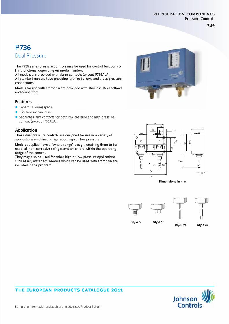
8/6/2019 Publ-6576 Prod Cat 11
http://slidepdf.com/reader/full/publ-6576-prod-cat-11 257/298
the european products catalogue 2011
For further information and additional models see Product Bulletin
249249
refrigeration components
Pressure Controls
The P736 series pressure controls may be used for control functions orlimit functions, depending on model number.All models are provided with alarm contacts (except P736ALA).All standard models have phosphor bronze bellows and brass pressureconnections.
Models for use with ammonia are provided with stainless steel bellowsand connectors.
Features z Generous wiring space
z
Trip-free manual reset z Separate alarm contacts for both low pressure and high pressurecut-out (except P736ALA)
ApplicationThese dual pressure controls are designed for use in a variety of applications involving refrigeration high or low pressure.
Models supplied have a “whole range” design, enabling them to beused all non-corrosive refrigerants which are within the operatingrange of the control.They may also be used for other high or low pressure applicationssuch as air, water etc. Models which can be used with ammonia areincluded in the program.
Dimensions in mm
70
13
132
42 28
75
25
11
55
25
19
51
112.5
6877
Style 5 Style 15Style 30Style 28
P736
Dual Pressure

8/6/2019 Publ-6576 Prod Cat 11
http://slidepdf.com/reader/full/publ-6576-prod-cat-11 258/298
the european products catalogue 2011
For further information and additional models see Product Bulletin
250
refrigeration components
Pressure Controls
P736 Dual Pressure Controls for Non-corrosive Refrigerants
FamilyCode
Left Side Right Side ContructionLP/HP
(max. press.)
Style 5 Style 30
PEDApprovalsRange (bar) Diff. (bar) Range (bar) Diff. (bar) Ind. Pack. Bulkpack Ind. Pack.
P736LCA -0.5 to 7 0.5 to 3 3 to 30 3 (fixed)
LP: 22bar
HP: 33 bar
-9300 -9320 -9400
---P736MCA -0.5 to 7 0.5 to 3 3 to 30 Man. Res.** -9300 -9320
---P736NGA -0.5 to 7 Man. Res.* 3 to 30 Auto Reset --- ***
P736PGA -0.5 to 7 Man. Res.* 3 to 30 Man. Res.** -9300 ---
P736 Dual Pressure Fan Cycling Controls for Air-Cooled Condensers (Non-corrosive Refrigerants)
FamilyCode
Left Side Right SideContruction
HP/HP(max. press.)
Style 5 Style 30
PEDApprovalsRange (bar) Diff. (bar) Range (bar) Diff. (bar) Ind. Pack. Bulkpack Ind. Pack.
P736ALA 3.5 to 21 1.8 (fixed) 3.5 to 21 1.8 (fixed) 30 bar -9351 **** --- ---
P736 Dual Pressure Controls for Non-Corrosive Refrigerants
FamilyCode
Left Side Right SideContruction
LP/HP(max. press.)
Style 5 Style 28
PEDApprovalsRange (bar) Diff. (bar) Range (bar) Diff. (bar) Ind. Pack. Bulkpack Ind. Pack.
P736LCW -0.5 to 7 0.6 to 3 3 to 30 3 (fixed)LP: 22 bar
HP: 33 bar
-9300 -9320-9800
P736MCB -0.5 to 7 0.6 to 3 3 to 30 Man. res.** -9300 ****
P736MCS -0.5 to 7 0,6 to 3 3 to 30 Man. res.** -9300 **** ---
P736 Dual Pressure Manual Reset HP/HP, TÜV-Begrenzer + Sicherheitsbegrenzer
FamilyCode
Left Side Right Side ContructionHP/HP
(max. press.)
Style 5 Style 30PED
ApprovalsRange (bar) Diff. (bar) Range (bar) Diff. (bar) Ind. Pack. Bulkpack Ind. Pack.
P736PLM 3 to 30 Man. res.** 3 to 30 Man. res.** 30 bar --- -9370
Notes* : Resetable at 0.5 bar above cut-out point** : Resetable at 3 bar below cut-out point*** : Can be set-up for quantity orders100 kPa = 1 bar ≈ 14.5 psi
P736Dual Pressure
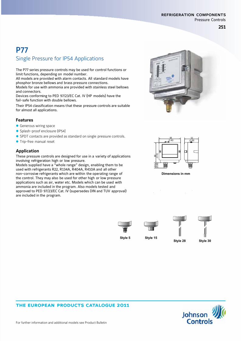
8/6/2019 Publ-6576 Prod Cat 11
http://slidepdf.com/reader/full/publ-6576-prod-cat-11 259/298
the european products catalogue 2011
For further information and additional models see Product Bulletin
251251
refrigeration components
Pressure Controls
...
Style 5 Style 15 Style 30Style 28
Dimensions in mm
2 2 , 5
( 0 . 8
9 )
8 0
( 3 . 1
5 )
88
(3.46) 53
(2.09)
...
The P77 series pressure controls may be used for control functions orlimit functions, depending on model number.All models are provided with alarm contacts. All standard models havephosphor bronze bellows and brass pressure connections.Models for use with ammonia are provided with stainless steel bellowsand connectors.Devices conforming to PED 97/23/EC Cat. IV (HP models) have thefail-safe function with double bellows.
Their IP54 classification means that these pressure controls are suitablefor almost all applications.
Features z Generous wiring space
z Splash-proof enclosure (IP54)
z SPDT contacts are provided as standard on single pressure controls.
z Trip-free manual reset
ApplicationThese pressure controls are designed for use in a variety of applicationsinvolving refrigeration high or low pressure.Models supplied have a “whole range” design, enabling them to beused with refrigerants R22, R134A, R404A, R410A and all othernon-corrosive refrigerants which are within the operating range of
the control. They may also be used for other high or low pressureapplications such as air, water etc. Models which can be used withammonia are included in the program. Also models tested andapproved to PED 97/23/EC Cat. IV (supersedes DIN and TUV approval)are included in the program.
P77
Single Pressure for IP54 Applications
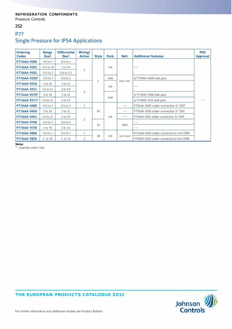
8/6/2019 Publ-6576 Prod Cat 11
http://slidepdf.com/reader/full/publ-6576-prod-cat-11 260/298
the european products catalogue 2011
For further information and additional models see Product Bulletin
252
refrigeration components
Pressure Controls
Ordering
Codes
Range
(bar)
Differential
(bar)
Wiring/
Action Style Pack. Refr. Additional Features
PED
ApprovalP77AAA-9300 -0.5 to 7 0.5 to 3
1
5
ind.
non-corr.
---
---
P77AAA-9301 -0.2 to 10 1 to 4.5
P77AAA-9302 -0.3 to 2 0.4 to 1.5
P77AAA-9320* -0.5 to 7 0.5 to 3 bulk Is P77AAA-9300 bulk pack
P77AAA-9350 3 to 30 3 to 12
2
ind. ---P77AAA-9351 3.5 to 21 2 to 5.5
P77AAA-9370* 3 to 30 3 to 12bulk
Is P77AAA-9350 bulk pack
P77AAA-9371* 3.5 to 21 2 to 5.5 Is P77AAA-9351 bulk pack
P77AAA-9400 -0.5 to 7 0.5 to 3 1
30
ind.
--- P77AAA-9300 solder connection ¼ “ODF
P77AAA-9450 3 to 30 3 to 12
2
--- P77AAA-9350 solder connection ¼ “ODF
P77AAA-9451 3.5 to 21 2 to 5.5 --- P77AAA-9351 solder connection ¼ “ODF
P77AAA-9700 -0.5 to 7 0.5 to 315 NH3
---
P77AAA-9750 3 to 30 3 to 12 ---
P77AAA-9800 -0.5 to 7 0.5 to 3 128 ind. non-corr.
P77AAA-9300 solder connection 6 mm ODM
P77AAA-9850 3 to 30 3 to 12 2 P77AAA-9350 solder connection 6 mm ODM
Notes* : Quantity orders only
P77Single Pressure for IP54 Applications

8/6/2019 Publ-6576 Prod Cat 11
http://slidepdf.com/reader/full/publ-6576-prod-cat-11 261/298
the european products catalogue 2011
For further information and additional models see Product Bulletin
253
refrigeration components
Pressure Controls
Ordering Codes
Range
(bar)
Diff.
(bar)
Wiring/
Action Style Pack. Refr. Additional Features
PED
ApprovalP77 Pressure Controls Automatic Recycle (Wächter, including lockplate assy)
P77AAW-9300 -0.5 to +7 0.5 to 3
1
---
ind.
non-corr.
---
---P77AAW-9301* -0.5 to +7 0.5 to 3Gold plated contacts; Fixed setting: Open:0,5 bar;Close: 1,25 bar
P77AAW-9320* -0.5 to +7 0.5 to 3 bulk P77AAW-9300 in bulk pack
P77AAW-9350 3 to 30 3.5 to 12
2
ind.
---
P77AAW-9353* 3 to 30 3.5 to 12
Gold plated contacts; Fixed setting: Open 7 bar;Close: 11 bar
P77AAW-9355 3 to 42 4 to 12 5 ind. ---
P77AAW-9370* 3 to 30 3.5 to 12 --- bulk P77AAW-9350 in bulk pack
P77AAW-9700 -0.5 to +7 0.5 to 3 1
15
ind.
NH3
--- ---
P77AAW-9750 3 to 30 3.5 to 12 2 •
P77AAW-9800 -0.5 to +7 0.5 to 3 1
28 non-corr.
P77AAW-9300 solder connection - 6 mm ODM ---
P77AAW-9850 3 to 30 3.5 to 12
2
P77AAW-9350 solder connection - 6 mm ODM
P77AAW-9851* 3 to 30 3.5 to 12Gold plated contacts; Fixed setting: Open 7 bar;Close: 11 bar, with solder connection 6 mm ODM
P77AAW-9855 3 to 42 4 to 12 2 ---
P77 Pressure Controls Manual Reset LP
P77BCA-9300
-0.5 to +7 --- 1
5
ind.
non-corr.
---
P77BCA-9400 30 P77BCA-9300 solder connection ¼ “ ODF
P77BCA-9700 15 NH3
P77BCB-9300 5
non-corr.P77BCB-9800 28 ind. P77BCB -9300 solder connection - 6 mm ODM
P77 Pressure Controls Manual Reset HP
P77BEA-9350
3 to 30 --- 3
5 ind.non-corr.
---
---P77BEA-9450 30ind.
P77BEA-9350 solder connection ¼ “ ODF
P77BEA-9750 15 NH3 ---
P77 Pressure Controls (Begrenzer, including lockplate assy)
P77BEB-9350 3 to 30
--- 3
5ind.
non-corr.---
P77BEB-9355 3 to 42
P77BEB-9370*
3 to 30
bulk P77BEB-9350 in bulk pack
P77BEB-9750 15
ind.
NH3 ---
P77BEB-9850 28 non-corr. P77BEB-9350 solder connection - 6 mm ODMP77BEB-9855 3 to 42 ---
P77 Pressure Controls (Sicherheltsdruckbegrenzer, including lockplate assy)
P77BES-9350
3 to 30 --- 3
5ind.
non-corr.---
P77BES-9370 bulk
P77BES-9750 15 ind. NH3
P77BES-9850 28 ind. non-corr. P77BES-9350 solder connection - 6 mm ODM
Note* : Quantity orders only
P77Single Pressure for IP54 Applications

8/6/2019 Publ-6576 Prod Cat 11
http://slidepdf.com/reader/full/publ-6576-prod-cat-11 262/298
the european products catalogue 2011
For further information and additional models see Product Bulletin
254
refrigeration components
Pressure Controls
22,5
80
122 53
.
.
.
Dimensions in mm
The P78 series pressure controls may be used for control functions orlimit functions, depending on model number.All models are provided with alarm contacts (except P78ALA).All standard models have phosphor bronze bellows and brass pressureconnections. Models for use with ammonia are provided with stainlesssteel bellows and connectors. Devices conforming to DIN 32733 have adouble bellows on the high pressure versions.
Their IP54 classification means that these pressure controls aresuitable for almost all applications.
Features z Generous wiring space z Splash-proof enclosure (IP54)
z Trip-free manual reset
z Patented separate alarm contacts for both low pressure and highpressure cut-out (except P78ALA)
ApplicationThese pressure controls are designed for use in a variety of applications involving refrigeration high or low pressure.Models supplied have a “whole range” design, enabling them to beused with refrigerants R22, R134A, R404A, R410A and all other non-corrosive refrigerants which are within the operating range of the
control.They may also be used for other high or low pressure applicationssuch as air, water etc. Models which can be used with ammonia areincluded in the program. Also models tested and approved to PED97/23/EC Cat. IV (supersedes DIN and TUV approval) are included in theprogram.
.
.
.
Style 5 Style 15 Style 30Style 28
P78
Dual Pressure for IP54 Applications
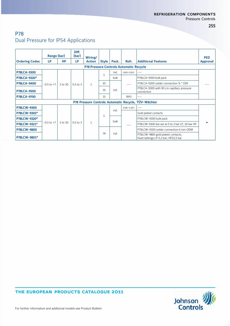
8/6/2019 Publ-6576 Prod Cat 11
http://slidepdf.com/reader/full/publ-6576-prod-cat-11 263/298
the european products catalogue 2011
For further information and additional models see Product Bulletin
255
refrigeration components
Pressure Controls
P78Dual Pressure for IP54 Applications
Ordering CodesRange (bar)
Diff.
(bar) Wiring/Action Style Pack. Refr. Additional Features
PEDApprovalLP HP LP
P78 Pressure Controls Automatic Recycle
P78LCA-9300
-0.5 to +7 3 to 30 0.5 to 3 1
5ind. non-corr. ---
---
P78LCA-9320* bulk
---
P78LCA-9300 bulk pack
P78LCA-9400 30
ind.
P78LCA-9300 solder connection ¼ “ ODF
P78LCA-9500 35P78LCA-9300 with 90 cm capillary pressureconnection
P78LCA-9700 15 NH3 ---
P78 Pressure Controls Automatic Recycle, TÜV-Wächter
P78LCW-9300
-0.5 to +7 3 to 30 0.5 to 3 1
5
ind.non-corr. ---
P78LCW-9302*
---
Gold plated contactsP78LCW-9320*
bulkP78LCW-9300 bulk pack
P78LCW-9321* P78LCW-9300 but set at 0 to 3 bar LP, 20 bar HP
P78LCW-980028 ind.
P78LCW-9300 solder connection 6 mm ODM
P78LCW-9801*P78LCW-9800 gold plated contacts,fixed settings LP 0,3 bar; HP22,5 bar

8/6/2019 Publ-6576 Prod Cat 11
http://slidepdf.com/reader/full/publ-6576-prod-cat-11 264/298
the european products catalogue 2011
For further information and additional models see Product Bulletin
256
refrigeration components
Pressure Controls
Ordering CodesRange (bar)
Diff.
(bar) Wiring/Action Style Pack. Refr. Additional Features
PEDApprovalLP HP LP
P78 Pressure Controls Manual reset HP
P78MCA-9300
-0.5 to +7 3 to 30 0.5 to 3 1
5 ind.non-corr.
---
---P78MCA-9400 30 ind. P78MCA-9300 solder connection ¼ “ ODF
P78MCA-9700 15 ind. NH3 ---
P78 Pressure Controls Manual reset LP/Auto. Reset HP
P78PGA-9300
-0.5 to +7 3 to 30 --- 1
5 ind.non-corr.
---
---P78PGA-9400 30Ind.
P78PGA-9300 solder connection ¼ “ ODF
P78PGA-9700 15 NH3 ---
P78 Pressure Controls Manual reset LP/HP
P78PGB-9300-0.5 to +7 3 to 30
---1
5 ind.non-corr.
---
P78PGB-9800 --- 28 ind P78PGB-9300 solder connection 6 mm ODM
P78 Pressure Controls Manual reset HP (Begrenzer, including lockplate assy)
P78MCB -9300
-0.5 to +7 3 to 30 0.5 to 3 15
ind.
non-corr.
---
P78MCB-9320* bulk P78MCB-9300 bulk pack
P78MCB-9800 28 ind. P78MCB-9300 solder connection 6 mm ODM
P78 Pressure Controls Manual reset HP (Sicherheltsdruckbegrenzer, including lockplate assy)
P78MCS-9300 -0.5 to +7 3 to 30 0.5 to 3 1 5 ind. non-corr. ---
P78 Pressure Controls Manual reset HP/HP (Begrenzer + Sicherheltsdruckbegrenzer, including lockplate assy)
P78PLM-93503 to 30 3 to 30 --- 2
5ind. non-corr.
---
P78PLM-9850 28 Is P78PLM-9350 solder connection 6 mm ODMP78 Dual Fan Cycling Controls
P78ALA-93513.5 to 21 3.5 to 21 --- 3
5ind. non-corr.
---
P78ALA-9451 30 Is P78ALA-9351 solder connection ¼ “ ODF
Note* : Quantity orders only
P78Dual Pressure for IP54 Applications
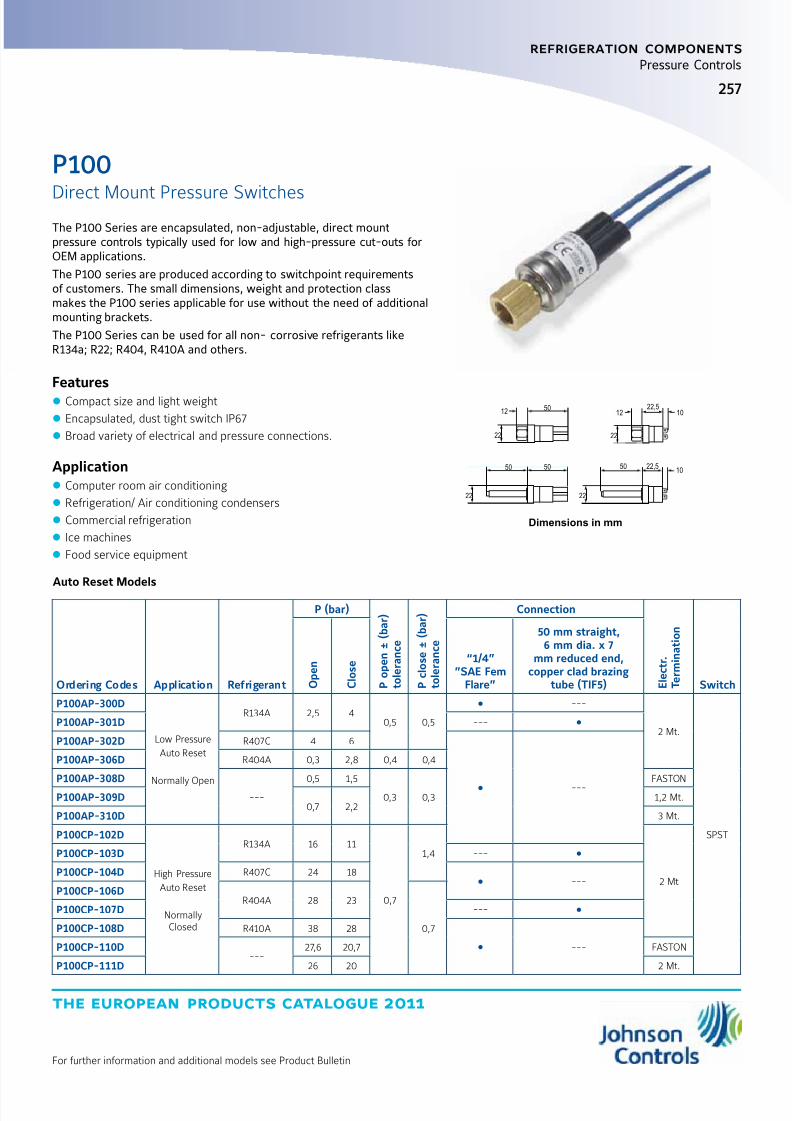
8/6/2019 Publ-6576 Prod Cat 11
http://slidepdf.com/reader/full/publ-6576-prod-cat-11 265/298
the european products catalogue 2011
For further information and additional models see Product Bulletin
257
refrigeration components
Pressure Controls
Dimensions in mm
22,5
22
2222
22
10
10
1212
50 22,550 50
50
The P100 Series are encapsulated, non-adjustable, direct mountpressure controls typically used for low and high-pressure cut-outs forOEM applications.
The P100 series are produced according to switchpoint requirementsof customers. The small dimensions, weight and protection classmakes the P100 series applicable for use without the need of additionalmounting brackets.
The P100 Series can be used for all non- corrosive refrigerants likeR134a; R22; R404, R410A and others.
Features z Compact size and light weight
z Encapsulated, dust tight switch IP67
z Broad variety of electrical and pressure connections.
Application z Computer room air conditioning
z Refrigeration/ Air conditioning condensers
z Commercial refrigeration
z Ice machines
z Food service equipment
P100
Direct Mount Pressure Switches
Auto Reset Models
Ordering Codes Application Refrigerant
P (bar)
P o p e n ± ( b a r )
t o l e r a n c e
P c l o s e ± ( b a r )
t o l e r a n c e
Connection
E l e c t r .
T e r m i n a t i o n
Switch O p e n
C l o s e “1/4”
”SAE FemFlare”
50 mm straight,6 mm dia. x 7
mm reduced end,copper clad brazing
tube (TIF5)
P100AP-300D
Low Pressure
Auto Reset
Normally Open
R134A 2,5 40,5 0,5
---
2 Mt.
SPST
P100AP-301D ---
P100AP-302D R407C 4 6
---
P100AP-306D R404A 0,3 2,8 0,4 0,4
P100AP-308D
---
0,5 1,5
0,3 0,3
FASTON
P100AP-309D0,7 2,2
1,2 Mt.
P100AP-310D 3 Mt.
P100CP-102D
High Pressure
Auto Reset
NormallyClosed
R134A 16 11
0,7
1,4
2 Mt
P100CP-103D ---
P100CP-104D R407C 24 18 ---
P100CP-106DR404A 28 23
0,7
P100CP-107D ---
P100CP-108D R410A 38 28
---P100CP-110D---
27,6 20,7 FASTON
P100CP-111D 26 20 2 Mt.

8/6/2019 Publ-6576 Prod Cat 11
http://slidepdf.com/reader/full/publ-6576-prod-cat-11 266/298
the european products catalogue 2011
For further information and additional models see Product Bulletin
258
refrigeration components
Pressure Controls
Manual Reset Models
Ordering Codes Application Refrigerant
P (bar)
P o p e n ± ( b a r )
t o l e r a n c e
P c l o
s e ± ( b a r )
t o l e r a n c e
Connection
E l e c t
r .
T e r m
i n a t i o n
( M t )
Switch O p e n
C l o s e
“1/4””SAE Fem
Flare”
50 mm straight, 6 mmdia. x 7 mm reduced
end, copper cladbrazing tube (TIF5)
P100DA-66D
High Pressure
Manual Reset
R134A 16
0,7
---
---2
SPST
P100DA-67D ---
P100DA-68DR407C 26
---
3P100DA-69D ---
P100DA-70DR404A 28
---
P100DA-71D ---
P100DA-72D
R410A
38
1,0
---
2P100DA-73D 38 ---
P100DA-74D R407C 26
0,7
---
1,2
P100DA-75DR410A
42 2
P100DA-76D 42 ---
Features
z Compact size and light weight z Encapsulated, dust tight switch IP67
z Manual reset models have a trip-free design
z Models with gold-plated contacts available
z Broad variety of electrical and pressure connections
Dimensions in mm
24 29 24
16 1650 21
1134
1116
P100Direct Mount Pressure Switches
Dimensions in mm
31 27
38
90
50
32
16
P100 Heavy Duty Pressure Controls - Auto Reset
Ordering Codes Application Refrigerant
P (bar)
P o p e n ± ( b a r )
t o l e r a n c e
P c l o s e ± ( b a r )
t o l e r a n c e
Connection
E l e c t r .
T e r m i n a t i o n
( M t )
Switch O p e n
C l o s e
“1/4”SAEFem
Flare”
50 mm straight,6 mm dia. x 7 mm
reduced end, copperclad brazing tube (TIF5)
P100EE-17DHigh Pressure
Auto Reset
Normallyclosed
R404A 20 251,0 1,0
---1,5
SPDT
P100EE-18D R134A 15 11
P100EE-60DR404A 28 21 0,7 0,7 2
P100EE-61D ---
P100EE-68D R134A 3 25 0,35 0,35 --- 1,8
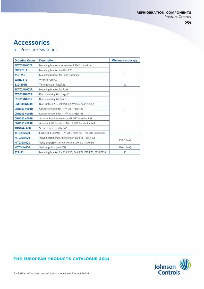
8/6/2019 Publ-6576 Prod Cat 11
http://slidepdf.com/reader/full/publ-6576-prod-cat-11 267/298
the european products catalogue 2011
For further information and additional models see Product Bulletin
259259
refrigeration components
Pressure Controls
Ordering Codes Description Minimum order qty.
BKT034N602R Mounting bracket + screws for P35AC transducer
1BKT275-1 Mounting bracket dual for P20
210-25R Mounting bracket for P20/P35 (single)
WRN12-1 Wrench P20/P21
210-604R Terminal cover P20/P21 50
BKT024N002R Mounting bracket for P233
1
FTG015N602R Duct mounting kit “staight”
FTG015N603R Duct mounting kit “bent”
GMT008N600R Duct kit for P233, self locking grommet and tubing
CNR003N001R Connector 6 mm for P77/P78, P735/P736
CNR003N002R Connector 8 mm for P77/P78, P735/P736
CNR012N001R Adapter R3/8 female to 1/4-18 NPT male for P48
CNR013N001R Adapter R 3/8 female to 1/4-18 NPT female for P48
TBG16A-600 Steam trap assembly P48
KIT023N600 Locking kit for P48, P77/P78, P735/P736 - for field installation
KIT031N600 Valve depressors for conversion style 13 - style 45a100 (1 box)
KIT031N601 Valve depressors for conversion style 51 - style 50
KIT034N600 Seal rings for style 50/51 250 (1 box)
271-51L Mounting bracket for P28, P45, P48, P74, P77/P78, P735/P736 50
Accessories
for Pressure Switches

8/6/2019 Publ-6576 Prod Cat 11
http://slidepdf.com/reader/full/publ-6576-prod-cat-11 268/298
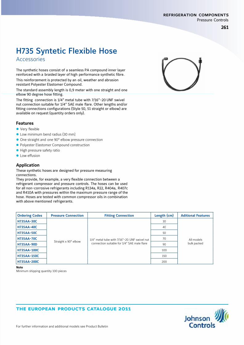
8/6/2019 Publ-6576 Prod Cat 11
http://slidepdf.com/reader/full/publ-6576-prod-cat-11 269/298
the european products catalogue 2011
For further information and additional models see Product Bulletin
261261
refrigeration components
Pressure Controls
H735 Syntetic Flexible Hose
Accessories
Ordering Codes Pressure Connection Fitting Connection Length (cm) Aditional Features
H735AA-30C
Straight x 90° elbow1/4” metal tube with 7/16”-20 UNF swivel nutconnection suitable for 1/4” SAE male flare
30
All modelsbulk packed
H735AA-40C 40
H735AA-50C 50
H735AA-70C 70
H735AA-90D 90
H735AA-100C 100
H735AA-150C 150
H735AA-200C 200
NoteMinimum shipping quantity 100 pieces
The synthetic hoses consist of a seamless PA compound inner layerreinforced with a braided layer of high performance synthetic fibre.
This reinforcement is protected by an oil, weather and abrasionresistant Polyester Elastomer Compound.
The standard assembly length is 0,9 meter with one straight and oneelbow 90 degree hose fitting.
The fitting connection is 1/4” metal tube with 7/16”-20 UNF swivelnut connection suitable for 1/4” SAE male flare. Other lengths and/orfitting connections configurations (Style 50, 51 straight or elbow) areavailable on request (quantity orders only).
Features z Very flexible
z Low minimum bend radius (30 mm)
z One straight and one 90° elbow pressure connection
z Polyester Elastomer Compound construction
z High pressure safety ratio
z Low effusion
ApplicationThese synthetic hoses are designed for pressure measuringconnections.
They provide, for example, a very flexible connection between arefrigerant compressor and pressure controls. The hoses can be usedfor all non-corrosive refrigerants including R134a, R22, R404a, R407cand R410A with pressures within the maximum pressure range of thehose. Hoses are tested with common compressor oils in combinationwith above mentioned refrigerants.
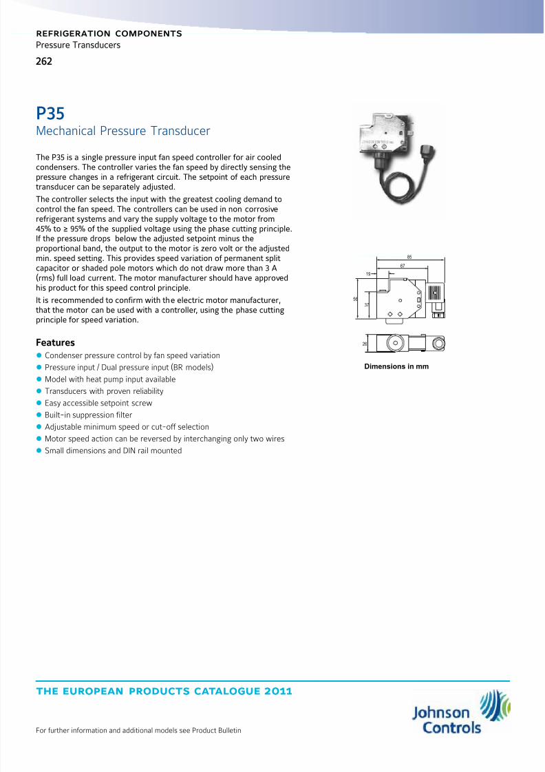
8/6/2019 Publ-6576 Prod Cat 11
http://slidepdf.com/reader/full/publ-6576-prod-cat-11 270/298
the european products catalogue 2011
For further information and additional models see Product Bulletin
262
refrigeration components
Pressure Transducers
Dimensions in mm
85
56
26
37
67
19
The P35 is a single pressure input fan speed controller for air cooledcondensers. The controller varies the fan speed by directly sensing thepressure changes in a refrigerant circuit. The setpoint of each pressuretransducer can be separately adjusted.
The controller selects the input with the greatest cooling demand tocontrol the fan speed. The controllers can be used in non corrosiverefrigerant systems and vary the supply voltage to the motor from45% to ≥ 95% of the supplied voltage using the phase cutting principle.If the pressure drops below the adjusted setpoint minus theproportional band, the output to the motor is zero volt or the adjustedmin. speed setting. This provides speed variation of permanent split
capacitor or shaded pole motors which do not draw more than 3 A(rms) full load current. The motor manufacturer should have approvedhis product for this speed control principle.
It is recommended to confirm with the electric motor manufacturer,that the motor can be used with a controller, using the phase cuttingprinciple for speed variation.
Features z Condenser pressure control by fan speed variation
z Pressure input / Dual pressure input (BR models)
z Model with heat pump input available
z Transducers with proven reliability
z
Easy accessible setpoint screw z Built-in suppression filter
z Adjustable minimum speed or cut-off selection
z Motor speed action can be reversed by interchanging only two wires
z Small dimensions and DIN rail mounted
P35
Mechanical Pressure Transducer

8/6/2019 Publ-6576 Prod Cat 11
http://slidepdf.com/reader/full/publ-6576-prod-cat-11 271/298
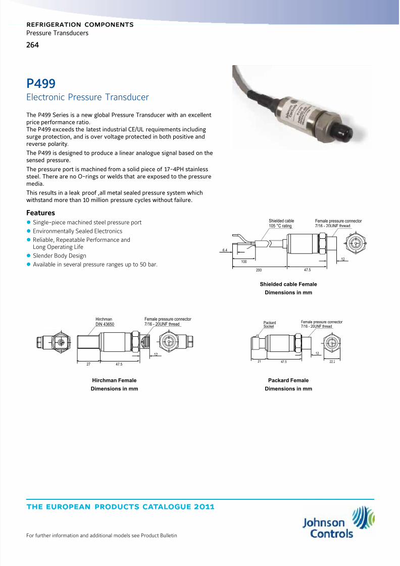
8/6/2019 Publ-6576 Prod Cat 11
http://slidepdf.com/reader/full/publ-6576-prod-cat-11 272/298
the european products catalogue 2011
For further information and additional models see Product Bulletin
264
refrigeration components
Pressure Transducers
Shielded cable105 °C rating
Female pressure connector 7/16 - 20UNF thread
100
6.4
200 47.5
12
Shielded cable Female
Dimensions in mm
Hirchman Female
Dimensions in mm
Packard Female
Dimensions in mm
HirchmanDIN 43650
Female pressure connector 7/16 - 20UNF thread
47.527
12
PackardSocket
Female pressure connector 7/16 - 20UNF thread
47.521
12
22.2
The P499 Series is a new global Pressure Transducer with an excellentprice performance ratio.The P499 exceeds the latest industrial CE/UL requirements includingsurge protection, and is over voltage protected in both positive andreverse polarity.
The P499 is designed to produce a linear analogue signal based on thesensed pressure.
The pressure port is machined from a solid piece of 17-4PH stainlesssteel. There are no O-rings or welds that are exposed to the pressuremedia.
This results in a leak proof ,all metal sealed pressure system which
withstand more than 10 million pressure cycles without failure.
Features z Single-piece machined steel pressure port
z Environmentally Sealed Electronics
z Reliable, Repeatable Performance andLong Operating Life
z Slender Body Design
z Available in several pressure ranges up to 50 bar.
P499
Electronic Pressure Transducer

8/6/2019 Publ-6576 Prod Cat 11
http://slidepdf.com/reader/full/publ-6576-prod-cat-11 273/298
the european products catalogue 2011
For further information and additional models see Product Bulletin
265
refrigeration components
Pressure Transducers
P499Electronic Pressure Transducer
2 meter cable Connections Models
Ordering Codes Press. Connection Output
P499-ABS-401CMale
0.4 to 20 mA
P499-ABS-404C
P499-ACS-401C
FemaleP499-ACS-404C
P499-ACS-405C
P499-VBS-401CMale
DC 0 V - 10 V
P499-VBS-404C
P499-VCS-401C
FemaleP499-VCS-404C
P499-VCS-405C
Hirschmann DIN connector
Ordering Codes Press. Connection Output
P499-ABH-401C
Male
0.4 to 20 mA
P499-ABH-402C
P499-ABH-404C
P499-ACH-401C
Female
P499-ACH-402C
P499-ACH-404C
P499-RCH-401C 0.5 - 4.5 VP499-RCH-404C
P499-VBH-401CMale
0 - 10 VP499-VBH-404C
P499-VCH-401CFemale
P499-VCH-404C
Packard connector
Ordering Codes Press. Connection Output
P499-ACP-401C
Female
0.4 to 20 mA
P499-ACP-402C
P499-ACP-403C
P499-ACP-404C
P499-ACP-405C
P499-RCP-401C
0.5 - 4.5 VP499-RCP-402C
P499-RCP-404C
P499-RCP-405C
P499-VCP-404C 0 - 10 V
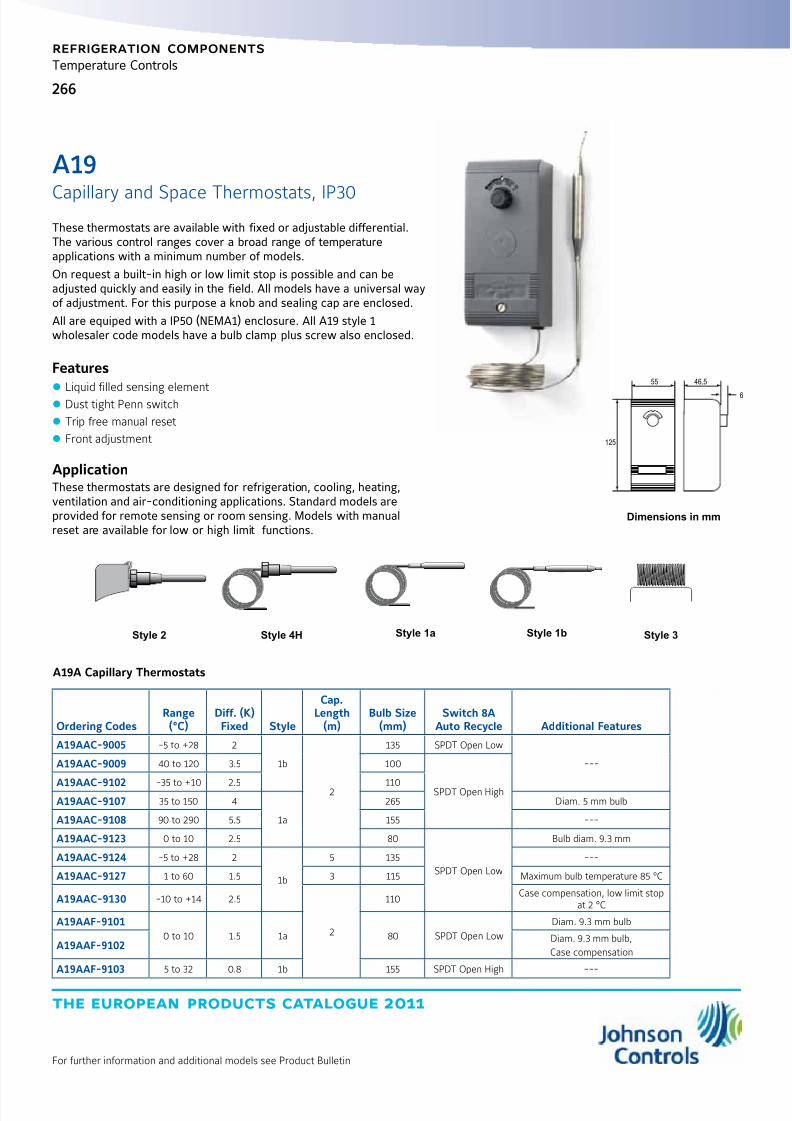
8/6/2019 Publ-6576 Prod Cat 11
http://slidepdf.com/reader/full/publ-6576-prod-cat-11 274/298
the european products catalogue 2011
For further information and additional models see Product Bulletin
266
refrigeration components
Temperature Controls
55
125
46,5
6
Dimensions in mm
Style 2 Style 4H Style 1a Style 3
These thermostats are available with fixed or adjustable differential.The various control ranges cover a broad range of temperatureapplications with a minimum number of models.
On request a built-in high or low limit stop is possible and can beadjusted quickly and easily in the field. All models have a universal wayof adjustment. For this purpose a knob and sealing cap are enclosed.
All are equiped with a IP50 (NEMA1) enclosure. All A19 style 1wholesaler code models have a bulb clamp plus screw also enclosed.
Features
z
Liquid filled sensing element z Dust tight Penn switch
z Trip free manual reset
z Front adjustment
ApplicationThese thermostats are designed for refrigeration, cooling, heating,ventilation and air-conditioning applications. Standard models areprovided for remote sensing or room sensing. Models with manualreset are available for low or high limit functions.
A19
Capillary and Space Thermostats, IP30
Style 1b
A19A Capillary Thermostats
Ordering CodesRange(°C)
Diff. (K)Fixed Style
Cap.Length
(m)Bulb Size
(mm)Switch 8A
Auto Recycle Additional Features
A19AAC-9005 -5 to +28 2
1b
2
135 SPDT Open Low
---A19AAC-9009 40 to 120 3.5 100
SPDT Open HighA19AAC-9102 -35 to +10 2.5 110A19AAC-9107 35 to 150 4
1a
265 Diam. 5 mm bulb
A19AAC-9108 90 to 290 5.5 155 ---
A19AAC-9123 0 to 10 2.5 80
SPDT Open Low
Bulb diam. 9.3 mm
A19AAC-9124 -5 to +28 2
1b
5 135 ---
A19AAC-9127 1 to 60 1.5 3 115 Maximum bulb temperature 85 °C
A19AAC-9130 -10 to +14 2.5
2
110Case compensation, low limit stop
at 2 °C
A19AAF-9101
0 to 10 1.5 1a 80 SPDT Open Low
Diam. 9.3 mm bulb
A19AAF-9102Diam. 9.3 mm bulb,
Case compensation
A19AAF-9103 5 to 32 0.8 1b 155 SPDT Open High ---

8/6/2019 Publ-6576 Prod Cat 11
http://slidepdf.com/reader/full/publ-6576-prod-cat-11 275/298
the european products catalogue 2011
For further information and additional models see Product Bulletin
267
refrigeration components
Temperature Controls
Ordering CodesRange(°C)
Diff. (K)Fixed Style
Cap.Length
(m)
BulbSize(mm)
Switch 8AAuto Recycle Additional Features
A19A Capillary Thermostats
A19ABC-9011
40 to 120 3 to 13
2 --- ---
SPDT Open High ½-14NPT ConnectorA19ABC-9012 4H 2 ---
A19ABC-9036 -35 to +402.8 to 8
1b
6.5
110
5 A Switch,
SPDT Open Low Universal replacement
A19ABC-9037 -35 to +40 3.5 ---
A19ABC-9103 -35 to +10 2.8 to 11 2SPDT Open Low ---
A19ABC-9104 -5 to +28 2 to 8 2 135
A19ABC-9106 10 to 95 3.5 to 14 1a 3.5 75 SPDT Open High Diam. 7.4 mm bulb
A19ABC-91161 to 60 2 to 8.5 1b
3115
SPDT Open Low
Max. bulb temp. 85 °CA19ABC-9117 5
A19AGF-9101* 0 to 13 1.5 fixed 1a 2 803 A Switch (see bull. 3545), No enclosure,Cal. pointer with dial, Screwdriver slot, Case
compensation, Bulb diam. 9.3 mm, Bulk packA19ACC Capillary Thermostat, lock-out low with Manual Reset
A19ACC-9100 -35 to +10 6
1b
2110
SPDT Open Low
---A19ACC-9101-5 to +28 4 135
A19ACC-9103 5
A19ACC-9105 -35 to +10 6 3.5 110 Low limit stop set at 2 °C
A19ACC-9107 -5 to +28 4 3 135 ---
A19ACC-9111-35 to +10 6
5110
Low limit stop set at 2 °C
A19ACC-9116 6.5 Low limit stop set at 3 °C, Universal replacement
A19ADC Capillary Thermostat, lock-out high with Manual Reset
A19ADC-9200 40 to 120 7 2 --- --- SPDT Open High 1/2-14 NPT connector
A19B Space Thermostats
A19BAC-9001 0 to 43 2
3 --- ---
SPDT Open High
Vinyl coated elementA19BAC-9250 -35 to +10 2.5
A19BAC-9251 -5 to +28 2 SPDT Open Low
A19BBC-9275 -35 to +40 2.8 to 8 SPDT Open Low, 5A
A19D Strap-On Thermostats
A19DAC-9001 40 to 120 4.5 20
--- --- SPDT Open High
8 A Switch, NEMA 1 enclosure, Universal adjustment,Including mounting strap
A19DAF-9001 92 to 116 2 203 A Switch, Universal adjustment,Including mounting strap
Note* : Quantity orders only
A19Capillary and Space Thermostats, IP30 55
125
46,5
6
26
Dimensions in mm

8/6/2019 Publ-6576 Prod Cat 11
http://slidepdf.com/reader/full/publ-6576-prod-cat-11 276/298
the european products catalogue 2011
For further information and additional models see Product Bulletin
268
refrigeration components
Temperature Controls
Dimensions in mm
A19A Capillary Thermostats
Ordering CodesRange(°C)
Diff. (K)Adjust. Style
Cap.Length
(m)
BulbSize(mm)
Switch 8AAuto Recycle Additional Features
A19ARC-9100 -35 to +10 2.8 to 11 1b 2 110
SPDT Open Low
---A19ARC-9101 -5 to +28 2 to 8 1b 2 135
A19ARC-9104 -20 to +65 3.5 to 13 1a 3.5 75 Diam. 7.4 mm bulb
A19ARC-9105 5 to 50 2.5 to 11 1b 2 110Concealed scale, Screwdriveradjustment,Bulb and cap. rubber coated
A19ARC-9107 40 to 120 3.5 to 13.5 1a 2 100 ---
A19ARC-91091 to 60 2 to 8.5 1a 3 115 Maximum bulb temperature 85 °C
A19ARC-9110 -10 to +50 2.5 to 11 1b 2 110Concealed scale, Screwdriveradjustment,
A19ARC-9113 -35 to +40 2.8 to 11 1b 2 110 ---
19125
115960
These thermostats are available with fixed or adjustable differential.The various control ranges cover a broad range of temperatureapplications with a minimum number of models.
SPDT contacts are standard on all models.
Features z Liquid filled sensing element
z Dust tight Penn switch
z IP65 protection class
z Front adjustment
ApplicationThese thermostats are designed for applications where a splash-proof and/or dust-tight enclosure is required.
Four types are available:
z Types A19ARC are general purpose capillary thermostats.
z Types A19BRC and A19BQC are space thermostats with coiledelement to be used as farm control, outdoor thermostats or in coldstorage rooms.
z Types A19AQF is specially designed for milkcool-tank applications.
z Type A19AQC-9101 is specially designed for ice-bank application.
A19
Capillary and Space Thermostats, IP65
Style 1a Style 3
Style 1b
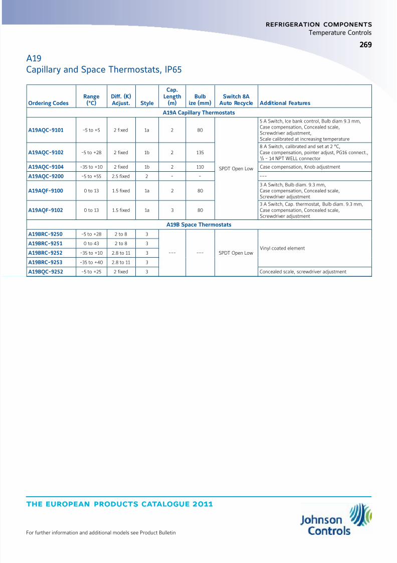
8/6/2019 Publ-6576 Prod Cat 11
http://slidepdf.com/reader/full/publ-6576-prod-cat-11 277/298
the european products catalogue 2011
For further information and additional models see Product Bulletin
269269
refrigeration components
Temperature Controls
A19Capillary and Space Thermostats, IP65
Ordering Codes Range(°C) Diff. (K)Adjust. Style
Cap.
Length(m) Bulbize (mm) Switch 8AAuto Recycle Additional Features
A19A Capillary Thermostats
A19AQC-9101 -5 to +5 2 fixed 1a 2 80
SPDT Open Low
5 A Switch, Ice bank control, Bulb diam 9.3 mm,Case compensation, Concealed scale,Screwdriver adjustment,Scale calibrated at increasing temperature
A19AQC-9102 -5 to +28 2 fixed 1b 2 1358 A Switch, calibrated and set at 2 °C,Case compensation, pointer adjust, PG16 connect.,½ - 14 NPT WELL connector
A19AQC-9104 -35 to +10 2 fixed 1b 2 110 Case compensation, Knob adjustment
A19AQC-9200 -5 to +55 2.5 fixed 2 - - ---
A19AQF-9100 0 to 13 1.5 fixed 1a 2 803 A Switch, Bulb diam. 9.3 mm,Case compensation, Concealed scale,
Screwdriver adjustment
A19AQF-9102 0 to 13 1.5 fixed 1a 3 803 A Switch, Cap. thermostat, Bulb diam. 9.3 mm,Case compensation, Concealed scale,Screwdriver adjustment
A19B Space Thermostats
A19BRC-9250 -5 to +28 2 to 8 3
--- --- SPDT Open LowVinyl coated element
A19BRC-9251 0 to 43 2 to 8 3
A19BRC-9252 -35 to +10 2.8 to 11 3
A19BRC-9253 -35 to +40 2.8 to 11 3
A19BQC-9252 -5 to +25 2 fixed 3 Concealed scale, screwdriver adjustment
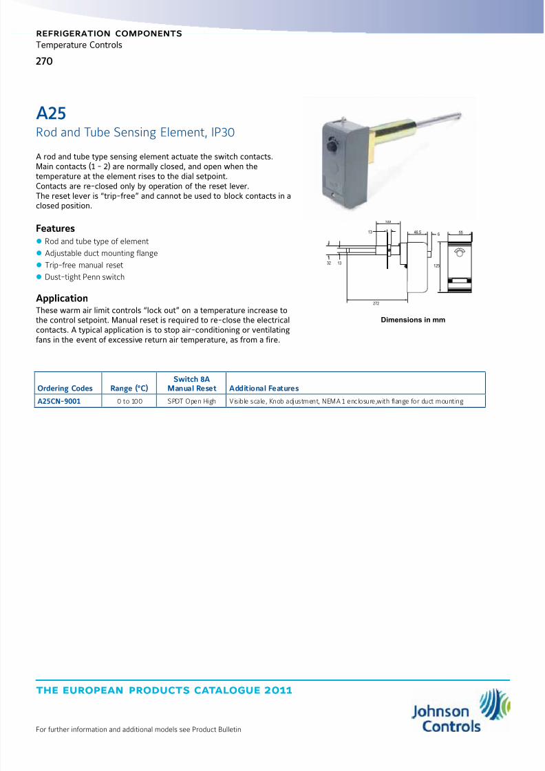
8/6/2019 Publ-6576 Prod Cat 11
http://slidepdf.com/reader/full/publ-6576-prod-cat-11 278/298
the european products catalogue 2011
For further information and additional models see Product Bulletin
270
refrigeration components
Temperature Controls
Ordering Codes Range (°C)Switch 8A
Manual Reset Additional Features
A25CN-90010 to 100 SPDT Open High Visible scale, Knob adjustment, NEMA 1 enclosure,with flange for duct mounting
Dimensions in mm
272
32 13
136
109
46.5 55
125
A rod and tube type sensing element actuate the switch contacts.Main contacts (1 - 2) are normally closed, and open when thetemperature at the element rises to the dial setpoint.Contacts are re-closed only by operation of the reset lever.The reset lever is “trip-free” and cannot be used to block contacts in aclosed position.
Features z Rod and tube type of element
z Adjustable duct mounting flange
z Trip-free manual reset
z Dust-tight Penn switch
ApplicationThese warm air limit controls “lock out” on a temperature increase tothe control setpoint. Manual reset is required to re-close the electricalcontacts. A typical application is to stop air-conditioning or ventilatingfans in the event of excessive return air temperature, as from a fire.
A25
Rod and Tube Sensing Element, IP30

8/6/2019 Publ-6576 Prod Cat 11
http://slidepdf.com/reader/full/publ-6576-prod-cat-11 279/298
the european products catalogue 2011
For further information and additional models see Product Bulletin
271271
refrigeration components
Temperature Controls
Dimensions in mm
55
125
46.5
Controls are compact with fixed differential per stage and (on mostmodels) adjustable differential between stages. Liquid filled elementprovides wide range, constant differential over whole range and noinfluence from barometric pressure.Since the bulb contains the major portion of the total fill thethermostat may by considered as cross-ambient, capillary and cuptemperature variations affect the operating point only slightly due tothe small amount of fill they contain.
For quantity orders it is possible to have the below stated optionalconstructions:
z Without case and cover for panel mounting
z Close differential per stage z Different capillary lengths
All standard IP30 enclosure models have a universal way of adjustment. For this purpose a knob and sealing cap are enclosed.
Features z Liquid filled sensing element
z Dust tight Penn switch
z IP65 protection class models available
z Front adjustment
ApplicationThese thermostats are designed for various types of heating, cooling,ventilation, or air-conditioning applications. All models have two SPDTswitches providing the following control possibilities:
z 2 stage heating
z 2 stage cooling
z Heating/cooling with automatic changeover
19
125
115960
A28
2-stage Capillary and Space Thermostats, IP30 / IP65
Style 3
Style 1b
IP30
IP65
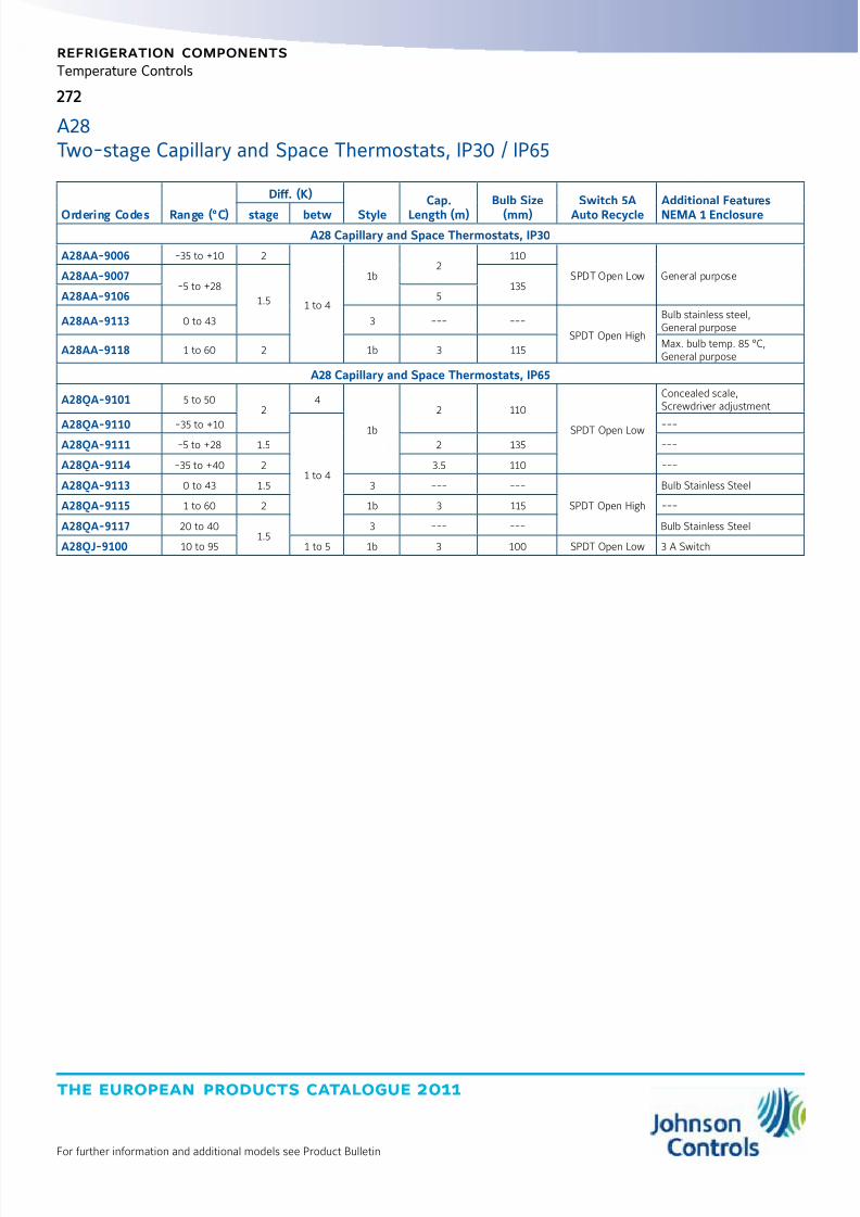
8/6/2019 Publ-6576 Prod Cat 11
http://slidepdf.com/reader/full/publ-6576-prod-cat-11 280/298
the european products catalogue 2011
For further information and additional models see Product Bulletin
272
refrigeration components
Temperature Controls
Ordering Codes Range (°C)
Diff. (K)
Style
Cap.
Length (m)
Bulb Size
(mm)
Switch 5A
Auto Recycle
Additional Features
NEMA 1 Enclosurestage betwA28 Capillary and Space Thermostats, IP30
A28AA-9006 -35 to +10 2
1 to 4
1b2
110
SPDT Open Low General purposeA28AA-9007-5 to +28
1.5135
A28AA-9106 5
A28AA-9113 0 to 43 3 --- ---
SPDT Open High
Bulb stainless steel,General purpose
A28AA-9118 1 to 60 2 1b 3 115Max. bulb temp. 85 °C,General purpose
A28 Capillary and Space Thermostats, IP65
A28QA-9101 5 to 502
4
1b
2 110
SPDT Open Low
Concealed scale,Screwdriver adjustment
A28QA-9110 -35 to +10
1 to 4
---A28QA-9111 -5 to +28 1.5 2 135 ---
A28QA-9114 -35 to +40 2 3.5 110 ---
A28QA-9113 0 to 43 1.5 3 --- ---
SPDT Open High
Bulb Stainless Steel
A28QA-9115 1 to 60 2 1b 3 115 ---
A28QA-9117 20 to 401.5
3 --- --- Bulb Stainless Steel
A28QJ-9100 10 to 95 1 to 5 1b 3 100 SPDT Open Low 3 A Switch
A28Two-stage Capillary and Space Thermostats, IP30 / IP65
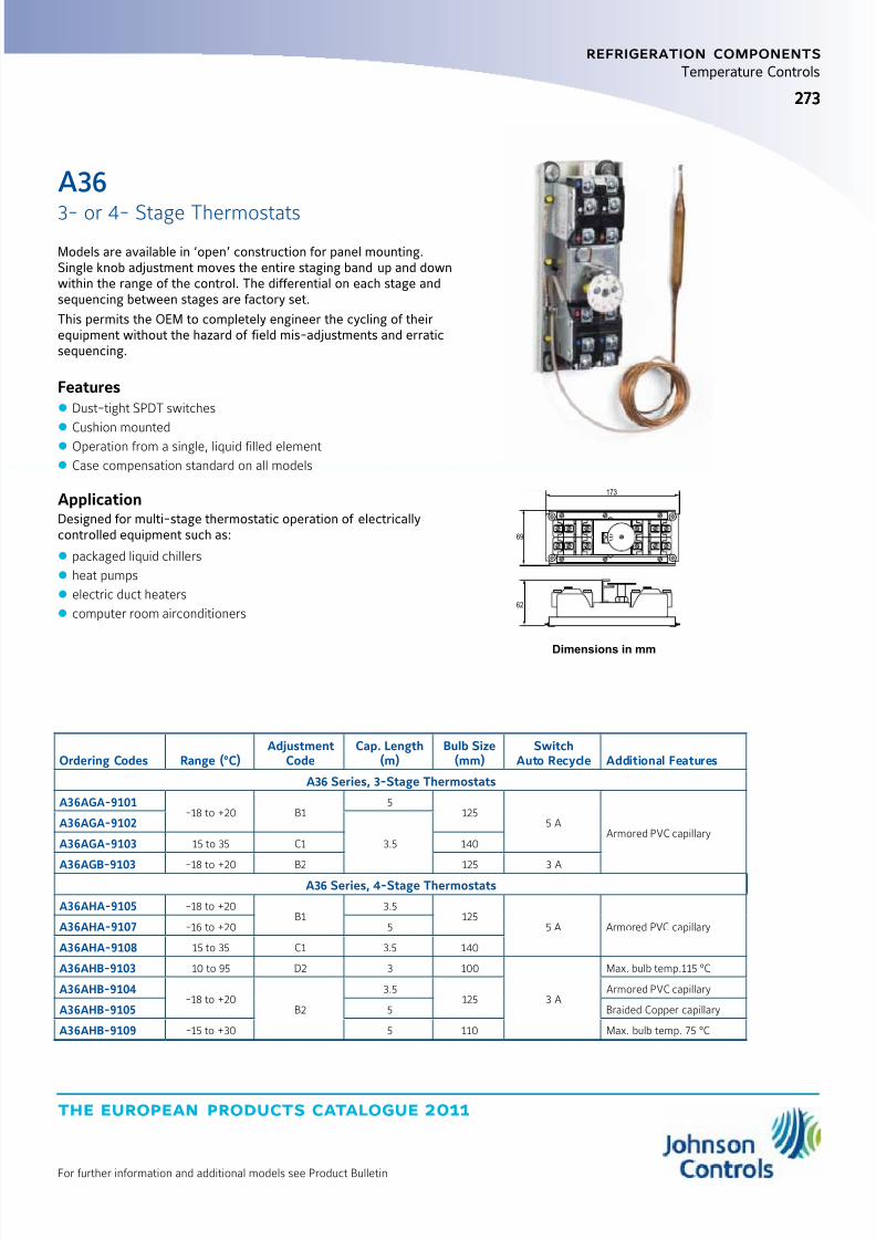
8/6/2019 Publ-6576 Prod Cat 11
http://slidepdf.com/reader/full/publ-6576-prod-cat-11 281/298
the european products catalogue 2011
For further information and additional models see Product Bulletin
273273
refrigeration components
Temperature Controls
Models are available in ‘open’ construction for panel mounting.Single knob adjustment moves the entire staging band up and downwithin the range of the control. The differential on each stage andsequencing between stages are factory set.
This permits the OEM to completely engineer the cycling of theirequipment without the hazard of field mis-adjustments and erraticsequencing.
Features z Dust-tight SPDT switches
z
Cushion mounted z Operation from a single, liquid filled element
z Case compensation standard on all models
ApplicationDesigned for multi-stage thermostatic operation of electricallycontrolled equipment such as:
z packaged liquid chillers
z heat pumps
z electric duct heaters
z computer room airconditioners
Dimensions in mm
69
62
173
Ordering Codes Range (°C)Adjustment
CodeCap. Length
(m)Bulb Size
(mm)Switch
Auto Recycle Additional Features
A36 Series, 3-Stage Thermostats
A36AGA-9101-18 to +20 B1
5125
5 AArmored PVC capillary
A36AGA-9102
3.5A36AGA-9103 15 to 35 C1 140
A36AGB-9103 -18 to +20 B2 125 3 AA36 Series, 4-Stage Thermostats
A36AHA-9105 -18 to +20B1
3.5125
5 A Armored PVC capillaryA36AHA-9107 -16 to +20 5
A36AHA-9108 15 to 35 C1 3.5 140
A36AHB-9103 10 to 95 D2 3 100
3 A
Max. bulb temp.115 °C
A36AHB-9104-18 to +20
B2
3.5125
Armored PVC capillary
A36AHB-9105 5 Braided Copper capillary
A36AHB-9109 -15 to +30 5 110 Max. bulb temp. 75 °C
A36
3- or 4- Stage Thermostats
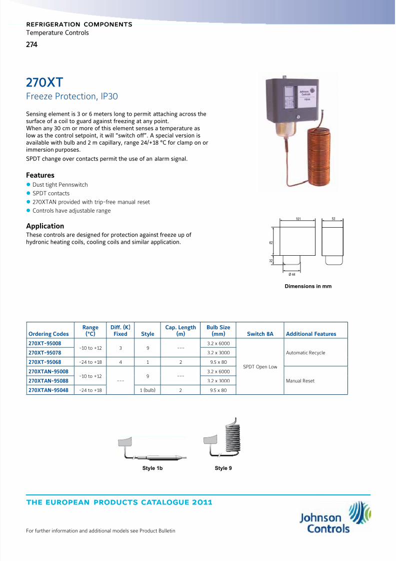
8/6/2019 Publ-6576 Prod Cat 11
http://slidepdf.com/reader/full/publ-6576-prod-cat-11 282/298
the european products catalogue 2011
For further information and additional models see Product Bulletin
274
refrigeration components
Temperature Controls
Ordering CodesRange(°C)
Diff. (K)Fixed Style
Cap. Length(m)
Bulb Size(mm) Switch 8A Additional Features
270XT-95008-10 to +12 3 9 ---
3.2 x 6000
SPDT Open Low
Automatic Recycle270XT-95078 3.2 x 3000
270XT-95068 -24 to +18 4 1 2 9.5 x 80
270XTAN-95008-10 to +12
---9 ---
3.2 x 6000
Manual Reset270XTAN-95088 3.2 x 3000
270XTAN-95048-24 to +18 1 (bulb) 2 9.5 x 80
Dimensions in mm
62
32
101 53
Ø 44
Sensing element is 3 or 6 meters long to permit attaching across thesurface of a coil to guard against freezing at any point.When any 30 cm or more of this element senses a temperature aslow as the control setpoint, it will “switch off”. A special version isavailable with bulb and 2 m capillary, range 24/+18 °C for clamp on orimmersion purposes.
SPDT change over contacts permit the use of an alarm signal.
Features z Dust tight Pennswitch
z
SPDT contacts z 270XTAN provided with trip-free manual reset
z Controls have adjustable range
ApplicationThese controls are designed for protection against freeze up of hydronic heating coils, cooling coils and similar application.
270XT
Freeze Protection, IP30
Style 9Style 1b
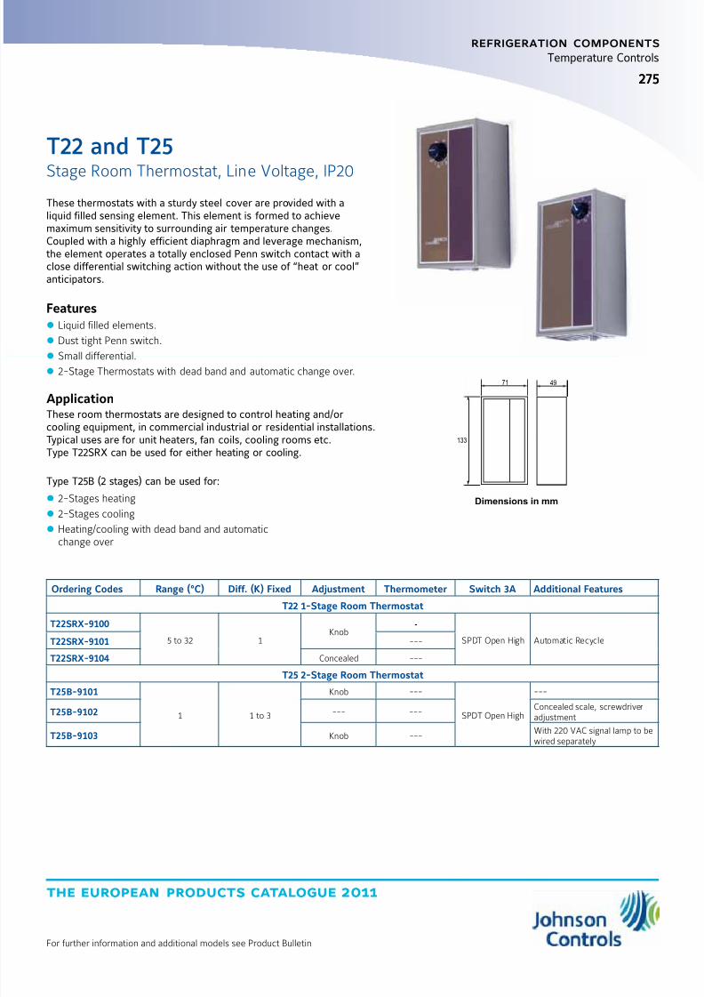
8/6/2019 Publ-6576 Prod Cat 11
http://slidepdf.com/reader/full/publ-6576-prod-cat-11 283/298
the european products catalogue 2011
For further information and additional models see Product Bulletin
275275
refrigeration components
Temperature Controls
These thermostats with a sturdy steel cover are provided with aliquid filled sensing element. This element is formed to achievemaximum sensitivity to surrounding air temperature changes.Coupled with a highly efficient diaphragm and leverage mechanism,the element operates a totally enclosed Penn switch contact with aclose differential switching action without the use of “heat or cool”anticipators.
Features z Liquid filled elements.
z Dust tight Penn switch.
z Small differential.
z 2-Stage Thermostats with dead band and automatic change over.
ApplicationThese room thermostats are designed to control heating and/orcooling equipment, in commercial industrial or residential installations.Typical uses are for unit heaters, fan coils, cooling rooms etc.Type T22SRX can be used for either heating or cooling.
Type T25B (2 stages) can be used for:
z 2-Stages heating
z 2-Stages cooling
z Heating/cooling with dead band and automaticchange over
Ordering Codes Range (°C) Diff. (K) Fixed Adjustment Thermometer Switch 3A Additional Features
T22 1-Stage Room Thermostat
T22SRX-9100
5 to 32 1Knob
•
SPDT Open High Automatic RecycleT22SRX-9101 ---
T22SRX-9104 Concealed ---
T25 2-Stage Room Thermostat
T25B-9101
1 1 to 3
Knob ---
SPDT Open High
---
T25B-9102 --- ---Concealed scale, screwdriveradjustment
T25B-9103 Knob ---With 220 VAC signal lamp to bewired separately
Dimensions in mm
133
71 49
T22 and T25
Stage Room Thermostat, Line Voltage, IP20
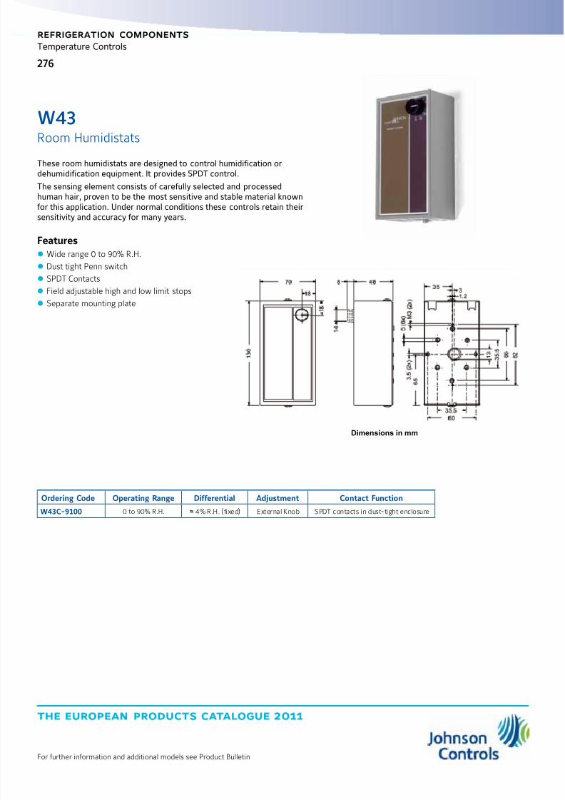
8/6/2019 Publ-6576 Prod Cat 11
http://slidepdf.com/reader/full/publ-6576-prod-cat-11 284/298
the european products catalogue 2011
For further information and additional models see Product Bulletin
276
refrigeration components
Temperature Controls
These room humidistats are designed to control humidification ordehumidification equipment. It provides SPDT control.
The sensing element consists of carefully selected and processedhuman hair, proven to be the most sensitive and stable material knownfor this application. Under normal conditions these controls retain theirsensitivity and accuracy for many years.
Features z Wide range 0 to 90% R.H.
z Dust tight Penn switch
z SPDT Contacts z Field adjustable high and low limit stops
z Separate mounting plate
W43
Room Humidistats
Ordering Code Operating Range Differential Adjustment Contact Function
W43C-9100 0 to 90% R.H. ≈ 4% R.H. (fixed) External Knob SPDT contacts in dust-tight enclosure
Dimensions in mm
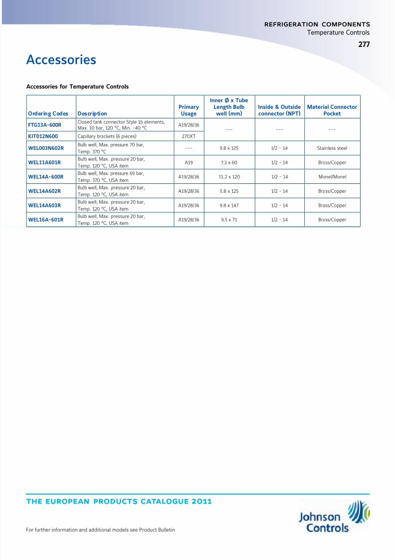
8/6/2019 Publ-6576 Prod Cat 11
http://slidepdf.com/reader/full/publ-6576-prod-cat-11 285/298
the european products catalogue 2011
For further information and additional models see Product Bulletin
277277
refrigeration components
Temperature Controls
Accessories
Accessories for Temperature Controls
Ordering Codes DescriptionPrimaryUsage
Inner Ø x TubeLength Bulbwell (mm)
Inside & Outsideconnector (NPT)
Material ConnectorPocket
FTG13A-600RClosed tank connector Style 1b elements,Max. 10 bar, 120 °C, Min. -40 °C
A19/28/36--- --- ---
KIT012N600 Capillary brackets (6 pieces) 270XT
WEL003N602RBulb well, Max. pressure 70 bar,
Temp. 370 °C--- 9.8 x 125 1/2 - 14 Stainless steel
WEL11A601RBulb well, Max. pressure 20 bar,
Temp. 120 °C, USA itemA19 7.3 x 60 1/2 - 14 Brass/Copper
WEL14A-600RBulb well, Max. pressure 69 bar,
Temp. 370 °C, USA itemA19/28/36 11.2 x 120 1/2 - 14 Monel/Monel
WEL14A602RBulb well, Max. pressure 20 bar,
Temp. 120 °C, USA item
A19/28/36 9.8 x 125 1/2 - 14 Brass/Copper
WEL14A603RBulb well, Max. pressure 20 bar,
Temp. 120 °C, USA itemA19/28/36 9.8 x 147 1/2 - 14 Brass/Copper
WEL16A-601RBulb well, Max. pressure 20 bar,
Temp. 120 °C, USA itemA19/28/36 9.5 x 71 1/2 - 14 Brass/Copper

8/6/2019 Publ-6576 Prod Cat 11
http://slidepdf.com/reader/full/publ-6576-prod-cat-11 286/298
the european products catalogue 2011
Manufacturer reserved the rights to change specifications without prior notice
Notes
8/6/2019 Publ-6576 Prod Cat 11
http://slidepdf.com/reader/full/publ-6576-prod-cat-11 287/298
the european products catalogue 2011
Manufacturer reserved the rights to change specifications without prior notice
index
hospitality solutions
XRM - eXtended Room Management
XRM System
Hotel Solutions 281
Web Server Software Options 282
Web Server Tower and Rack Solution 283
Area Network Controller 284Guest Cards and Card Writer 285
XRM Room Terminals
Access Reader 286
Enabler Reader 287
Room Thermostat 288
XRM Accessories Door Strike 289

8/6/2019 Publ-6576 Prod Cat 11
http://slidepdf.com/reader/full/publ-6576-prod-cat-11 288/298
the european products catalogue 2011
Manufacturer reserved the rights to change specifications without prior notice
Notes
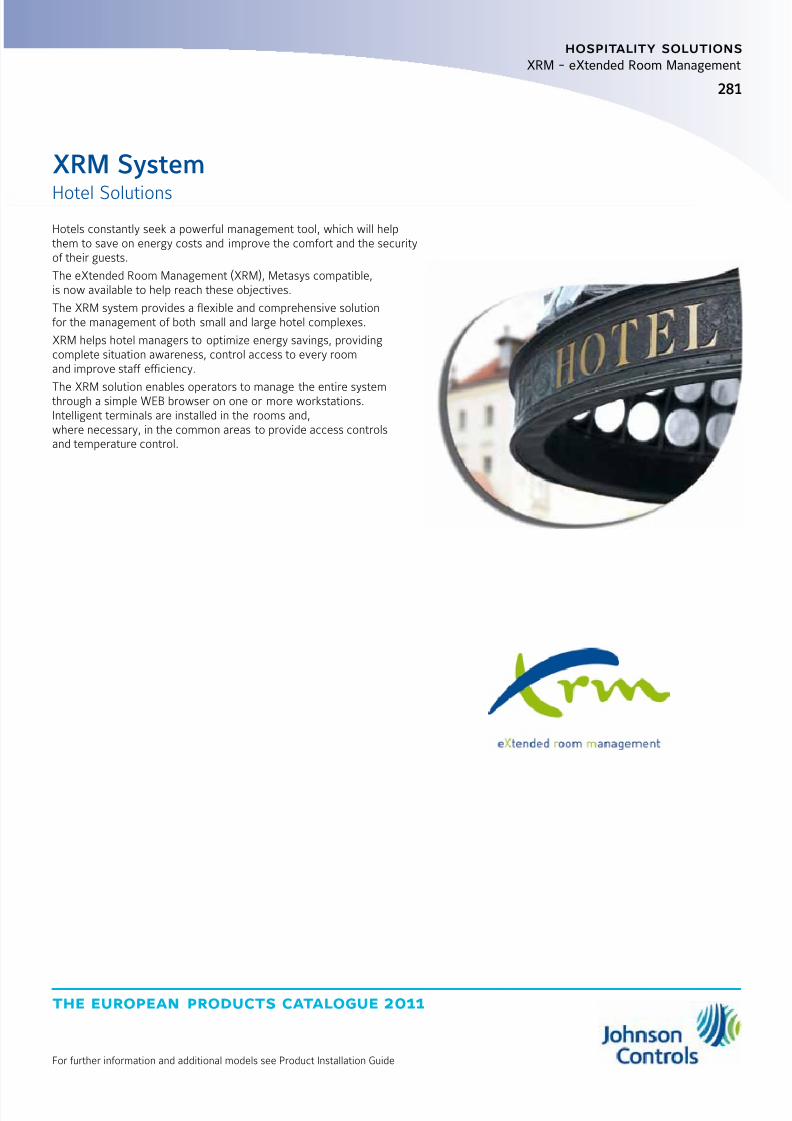
8/6/2019 Publ-6576 Prod Cat 11
http://slidepdf.com/reader/full/publ-6576-prod-cat-11 289/298
the european products catalogue 2011
For further information and additional models see Product Installation Guide
281
hospitality solutions
XRM - eXtended Room Management
Hotel Solutions
XRM System
Hotels constantly seek a powerful management tool, which will helpthem to save on energy costs and improve the comfort and the securityof their guests.
The eXtended Room Management (XRM), Metasys compatible,is now available to help reach these objectives.
The XRM system provides a flexible and comprehensive solutionfor the management of both small and large hotel complexes.
XRM helps hotel managers to optimize energy savings, providingcomplete situation awareness, control access to every roomand improve staff efficiency.
The XRM solution enables operators to manage the entire systemthrough a simple WEB browser on one or more workstations.Intelligent terminals are installed in the rooms and,where necessary, in the common areas to provide access controlsand temperature control.
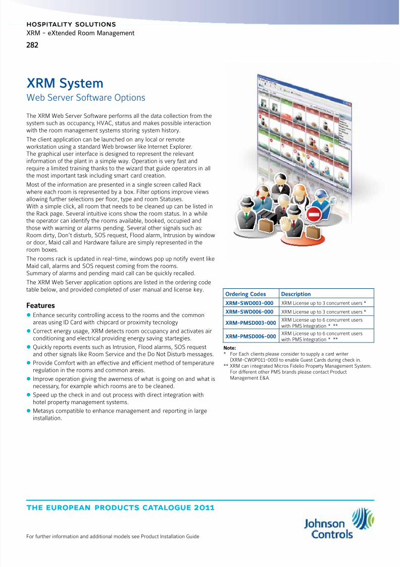
8/6/2019 Publ-6576 Prod Cat 11
http://slidepdf.com/reader/full/publ-6576-prod-cat-11 290/298
the european products catalogue 2011
282
For further information and additional models see Product Installation Guide
XRM - eXtended Room Management
hospitality solutions
Ordering Codes Description
XRM-SWD003-000 XRM License up to 3 concurrent users *
XRM-SWD006-000 XRM License up to 3 concurrent users *
XRM-PMSD003-000XRM License up to 6 concurrent userswith PMS Integration * **
XRM-PMSD006-000XRM License up to 6 concurrent userswith PMS Integration * **
Note:* For Each clients please consider to supply a card writer
(XRM-CW0P011-000) to enable Guest Cards during check in.** XRM can integrated Micros Fidelio Property Management System.
For different other PMS brands please contact ProductManagement E&A.
Web Server Software Options
XRM System
The XRM Web Server Software performs all the data collection from thesystem such as occupancy, HVAC, status and makes possible interactionwith the room management systems storing system history.
The client application can be launched on any local or remoteworkstation using a standard Web browser like Internet Explorer.The graphical user interface is designed to represent the relevantinformation of the plant in a simple way. Operation is very fast andrequire a limited training thanks to the wizard that guide operators in allthe most important task including smart card creation.
Most of the information are presented in a single screen called Rackwhere each room is represented by a box. Filter options improve views
allowing further selections per floor, type and room Statuses.With a simple click, all room that needs to be cleaned up can be listed inthe Rack page. Several intuitive icons show the room status. In a whilethe operator can identify the rooms available, booked, occupied andthose with warning or alarms pending. Several other signals such as:Room dirty, Don’t disturb, SOS request, Flood alarm, Intrusion by windowor door, Maid call and Hardware failure are simply represented in theroom boxes.
The rooms rack is updated in real-time, windows pop up notify event likeMaid call, alarms and SOS request coming from the rooms.Summary of alarms and pending maid call can be quickly recalled.
The XRM Web Server application options are listed in the ordering codetable below, and provided completed of user manual and license key.
Features
z Enhance security controlling access to the rooms and the commonareas using ID Card with chipcard or proximity tecnology
z Correct energy usage, XRM detects room occupancy and activates airconditioning and electrical providing energy saving startegies.
z Quickly reports events such as Intrusion, Flood alarms, SOS requestand other signals like Room Service and the Do Not Disturb messages.
z Provide Comfort with an effective and efficient method of temperatureregulation in the rooms and common areas.
z Improve operation giving the awerness of what is going on and what isnecessary, for example which rooms are to be cleaned.
z
Speed up the check in and out process with direct integration withhotel property management systems.
z Metasys compatible to enhance management and reporting in largeinstallation.
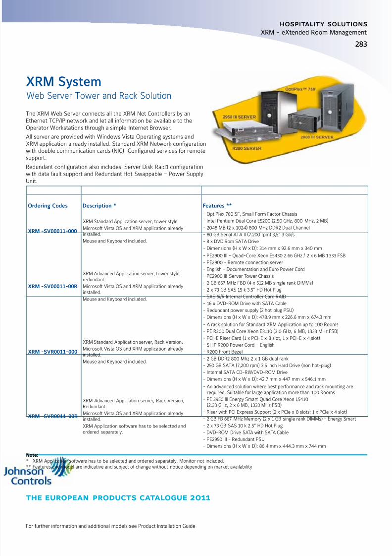
8/6/2019 Publ-6576 Prod Cat 11
http://slidepdf.com/reader/full/publ-6576-prod-cat-11 291/298

8/6/2019 Publ-6576 Prod Cat 11
http://slidepdf.com/reader/full/publ-6576-prod-cat-11 292/298
the european products catalogue 2011
284
For further information and additional models see Product Installation Guide
XRM - eXtended Room Management
hospitality solutions
Area Network Controller
XRM System
The XRM Area Network Controller provides full control and localmanagement of multiple hotel areas such as Rooms, Suites and othercommon areas. The Net Controller manages up to 32 room terminalsthrough a bus RS-485 or 10 rooms.
All XRM Area Network Controller are connected to the Roommanagement system Server by mean of a 10 / 100 Mbps Ethernet port.Thought-out the same network the XRM Net controller can be integratedin the Metasys Extended Architecture.
The XRM Area Network Controller provides power to the room terminalsand door locks with a built in power supply from 100-240Vac to 28 Vdc50 VA which is able to recharge back up battery. LED indication for Main
fails, battery fault or disconnected and data transmission on RS485.
Ordering Codes Description
XRM-NC00011-000 XRM Area Network Controller for managing of up to 32 room terminals
Technical Features
Supply Voltage 100 - 240 Vac, 50-60Hz
Rated Burden 50 VA
Working Conditions 0 to 50°C, 10 to 90% RH
Terminals 1.5 mm2 / 16 AWG
Serial Interface RS485 optoinsulated
User Interface Battery fault signaling LED, mains supply, bus power, TX
Inputs Ethernet 10 / 100 Cat. 5 Plug RJ45 network, RS-232
Terminal Supply 28 VDC protected by short circuit 2 A
Mounting In a switchboard on DIN rail or by screws
Dimensions (W x H x D) 210 x 108 x 50 mm, 12 module DIN
Housing Metallic
Compliance CE

8/6/2019 Publ-6576 Prod Cat 11
http://slidepdf.com/reader/full/publ-6576-prod-cat-11 293/298
the european products catalogue 2011
For further information and additional models see Product Installation Guide
285
hospitality solutions
XRM - eXtended Room Management
Guest Cards and Card Writer
XRM System
The eXtended Room management System can support either Chipcardthan Proximity card technology to identify Guest and Hotel Staff persons.
Through the XRm Server the cards can be generate using a Smart CardWriter connected by USB to reception stations.
XRM Desktop smart card writer
The desktop smart card writer is an USB plug and play device able toread and write smart cards: MIFARE 13.56 MHz contactless smart cardsand virtually any contact chip cards.
Contact Smart cards
The XRM system uses white PVC smart chip cards (ISO 7816) whichincludes microprocessor and memory. Data on the Card memory isprotected by a security code to avoid tamper attempts. Card will haveunique ID to avoid the misuse of the card on other hotel installation.
Contactless Smart card
Contactless smart cards are made according to ISO14443 standard.Data on the Card memory are protected by a security code to avoidtamper attempts. Card will have unique ID to avoid the misuse of thecard on other hotel installation.
Ordering Codes Description
XRM-CW0P011-000 USB proximity and chip card writer
Ordering Codes Description
XRM-CRDC011-000
Chip card technology
User ROM: 2-Kbyte
Manufacturer ROM: 4-Kbyte EEPROM,RAM: 256-byte
Chip: INFINEON, Atmel, ST
Dimensions (H x W x D): 86 x 54 x 0.8 mmStandard credit card
Ordering Codes Description
XRM-CRDP011-000
Proximity white card MIFARE® technology
Technology: MIFARE®
Reading: Proximity Contactlesstransmission of data and supplyenergy (no battery needed)
Operating distance: Up to 30 mm
Operating frequency: 13.56 MHz
EEPROM: 1 Kbyte, organized in 16 sectorswith 4 blocks of 16 bytes each(16 byte each block)
Dimensions (H x W x D): 86 x 54 x 0.8 mmStandard credit card
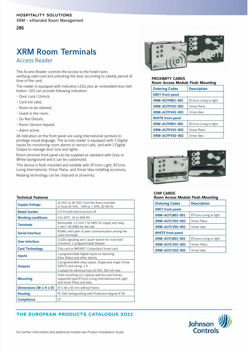
8/6/2019 Publ-6576 Prod Cat 11
http://slidepdf.com/reader/full/publ-6576-prod-cat-11 294/298
the european products catalogue 2011
286
For further information and additional models see Product Installation Guide
XRM - eXtended Room Management
hospitality solutions
Access Reader
XRM Room Terminals
The Access Reader controls the access to the hotel room,verifying valid card and unlocking the door according to validity period of time of the card.
The reader is equipped with indication LEDs plus an embedded door bellbutton. LED can provide following indication:
- Door Lock / Unlock,
- Card not valid,
- Room to be cleaned,
- Guest in the room,
- Do Not Disturb,
- Room Service request,
- Alarm active.
All indication on the front panel are using international symbols toprivilege visual language. The access reader is equipped with 3 Digitalinputs for monitoring room alarms or service calls, and with 3 DigitalOutput to manage door lock and lights.
Room terminal front panel can be supplied as standard with Grey orWhite background and it can be customized.
This device is flush mounted and suitable with BTicino Light, BTicinoLiving International, Vimar Plana, and Vimar Idea installing accessory.
Reading technology can be chipcard or proximity.
Technical Features
Supply Voltage16 VDC to 28 VDC From the Area controlleror local 24 VAC, -15% to + 10%, 50-60 Hz
Rated burden 0.9 VA with electrical lock off
Working conditions 0 to 50°C, 10 to 90% RH
TerminalsRemovable, 1.5 mm2 / 16 AWG for supply and relay,1 mm2 / 20 AWG for the rest
Serial interfaceRS485, with peer to peer communication among theroom terminals
User interface3 LEDs signaling and 1 push-button for room bellactivation, 1 programmable bleeper
Card Technology Chip card or MIFARE® Contactless Smart card
Inputs3 programmable Digital inputs to reporting:Door Status and other alarms
Outputs2 programmable relay output, Single pole single throw(SPST), and rating: 2 A
1 output for electrical lock 12 VDC 250 mA max.
MountingFlush mounting on 3 spaces wall box and frames,supported type BTicino Living international and Lightand Vimar Plana and Idea.
Dimensions (W x H x D) 67 x 46 x 56 mm without frame
Housing PC Self-extinguishing with Protection degree IP 30
Compliance CE
PROXIMITY CARDSRoom Access Module Flush Mounting
Ordering Codes Description
GREY front panel
XRM-ACFPB01-001 BTicino Living or light
XRM-ACFPV01-001 Vimar Plana
XRM-ACFPV02-001 Vimar Idea
WHITE front panel
XRM-ACFPB01-002 BTicino Living or light
XRM-ACFPV01-002 Vimar Plana
XRM-ACFPV02-002 Vimar Idea
CHIP CARDSRoom Access Module Flush Mounting
Ordering Codes Description
GREY front panel
XRM-ACFCB01-001 BTicino Living or light
XRM-ACFCV01-001 Vimar Plana
XRM-ACFCV02-001 Vimar Idea
WHITE front panel
XRM-ACFCB01-002 BTicino Living or light
XRM-ACFCV01-002 Vimar PlanaXRM-ACFCV02-002 Vimar Idea

8/6/2019 Publ-6576 Prod Cat 11
http://slidepdf.com/reader/full/publ-6576-prod-cat-11 295/298
the european products catalogue 2011
For further information and additional models see Product Installation Guide
287
hospitality solutions
XRM - eXtended Room Management
Enabler Reader
XRM Room Terminals
The Enabler reader installed inside the room is providing Occupancystatus activating lights and the air conditioning systems.The Enabler reader can, depending on model, read Chip card or Proximityaccording to technology chosen for the Access reader.This room terminal is equipped with 3 Digital inputs for monitoringroom alarms or service calls, and with 3 Digital Output to manage doorlock and lights. The reader is equipped with indication LEDs plus anembedded push button for activate the Do Not Disturb (DnD) status LEDcan provide following indication: Room Active, DnD and Alarm active.All indication on the front panel are using international symbols toprivilege visual language.
Room terminal front panel can be supplied as standard with Grey orWhite background and it can be customized.
This device is flush mounted and suitable with BTicino Light, BTicinoLiving International, Vimar Plana, and Vimar Idea installing accessory.
Technical Features
Supply Voltage16 VDC to 28 VDC From the Area controlleror local 24 VAC, -15% to + 10%, 50-60 Hz
Rated burden 0.9 VA with electrical lock off
Working conditions 0 to 50°C, 10 to 90% RH
TerminalsRemovable, 1.5 mm2 / 16 AWG for supply and relay,1 mm2 / 20 AWG for the rest
Serial interfaceRS485, with peer to peer communication among theroom terminals
User interface3 LEDs signaling and 1 push-button for room bellactivation, 1 programmable bleeper
Card Technology Chip card or MIFARE® Contactless Smart card
Inputs3 programmable Digital inputs to reporting:Room alarms and other service
Outputs2 programmable relay output,Single pole single throw (SPST), and rating: 2 A
1 output for electrical lock 12 VDC 250 mA max.
MountingFlush mounting on 3 spaces wall box and frames,supported type BTicino Living internationaland Light and Vimar Plana and Idea.
Dimensions (W x H x D) 67 x 46 x 56 mm without frame
Housing PC Self-extinguishing with Protection degree IP 30
Compliance CE
PROXIMITY CARDSRoom Enabler Module Flush Mounting
Ordering Codes Description
GREY front panel
XRM-ENFPB01-001 BTicino Living or light
XRM-ENFPV01-001 Vimar Plana
XRM-ENFPV02-001 Vimar Idea
WHITE front panel
XRM-ENFPB01-002 BTicino Living or light
XRM-ENFPV01-002 Vimar Plana
XRM-ENFPV02-002 Vimar Idea
CHIP CARDSRoom Enabler Module Flush Mounting
Ordering Codes Description
GREY front panel
XRM-ENFCB01-001 BTicino Living or light
XRM-ENFCV01-001 Vimar Plana
XRM-ENFCV02-001 Vimar Idea
WHITE front panel
XRM-ENFCB01-002 BTicino Living or light
XRM-ENFCV01-002 Vimar Plana
XRM-ENFCV02-002 Vimar Idea
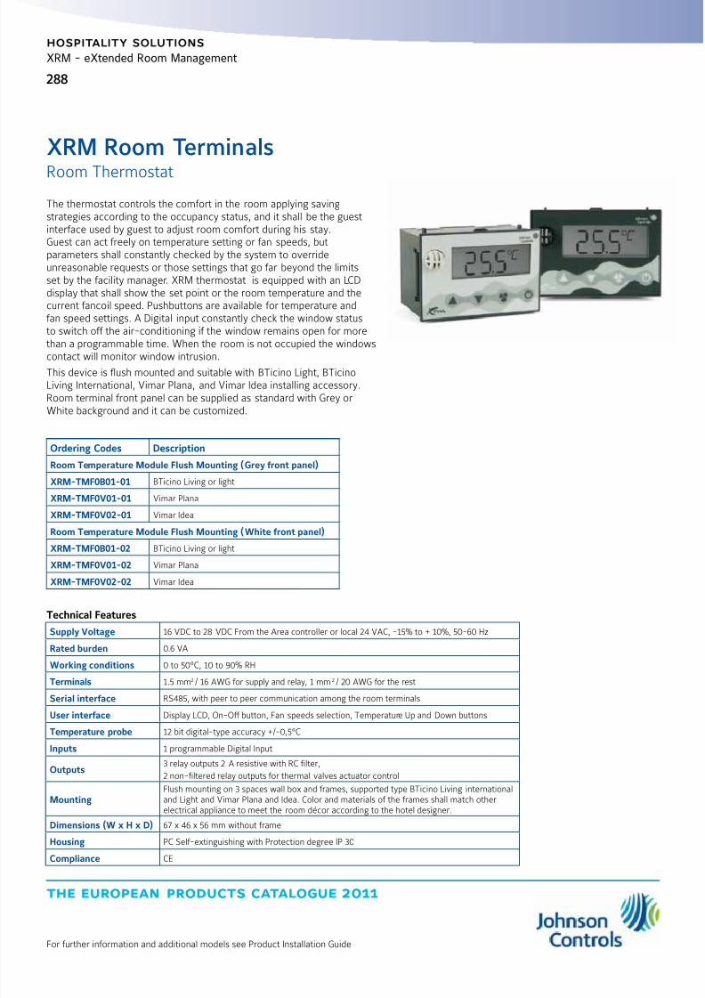
8/6/2019 Publ-6576 Prod Cat 11
http://slidepdf.com/reader/full/publ-6576-prod-cat-11 296/298
the european products catalogue 2011
288
For further information and additional models see Product Installation Guide
XRM - eXtended Room Management
hospitality solutions
Room Thermostat
XRM Room Terminals
The thermostat controls the comfort in the room applying savingstrategies according to the occupancy status, and it shall be the guestinterface used by guest to adjust room comfort during his stay.Guest can act freely on temperature setting or fan speeds, butparameters shall constantly checked by the system to overrideunreasonable requests or those settings that go far beyond the limitsset by the facility manager. XRM thermostat is equipped with an LCDdisplay that shall show the set point or the room temperature and thecurrent fancoil speed. Pushbuttons are available for temperature andfan speed settings. A Digital input constantly check the window statusto switch off the air-conditioning if the window remains open for morethan a programmable time. When the room is not occupied the windowscontact will monitor window intrusion.
This device is flush mounted and suitable with BTicino Light, BTicinoLiving International, Vimar Plana, and Vimar Idea installing accessory.Room terminal front panel can be supplied as standard with Grey orWhite background and it can be customized.
Ordering Codes Description
Room Temperature Module Flush Mounting (Grey front panel)
XRM-TMF0B01-01 BTicino Living or light
XRM-TMF0V01-01 Vimar Plana
XRM-TMF0V02-01 Vimar Idea
Room Temperature Module Flush Mounting (White front panel)
XRM-TMF0B01-02 BTicino Living or light
XRM-TMF0V01-02 Vimar Plana
XRM-TMF0V02-02 Vimar Idea
Technical Features
Supply Voltage 16 VDC to 28 VDC From the Area controller or local 24 VAC, -15% to + 10%, 50-60 Hz
Rated burden 0.6 VA
Working conditions 0 to 50°C, 10 to 90% RH
Terminals 1.5 mm2 / 16 AWG for supply and relay, 1 mm2 / 20 AWG for the rest
Serial interface RS485, with peer to peer communication among the room terminalsUser interface Display LCD, On-Off button, Fan speeds selection, Temperature Up and Down buttons
Temperature probe 12 bit digital-type accuracy +/-0,5°C
Inputs 1 programmable Digital Input
Outputs3 relay outputs 2 A resistive with RC filter,
2 non-filtered relay outputs for thermal valves actuator control
MountingFlush mounting on 3 spaces wall box and frames, supported type BTicino Living internationaland Light and Vimar Plana and Idea. Color and materials of the frames shall match otherelectrical appliance to meet the room décor according to the hotel designer.
Dimensions (W x H x D) 67 x 46 x 56 mm without frame
Housing PC Self-extinguishing with Protection degree IP 30
Compliance CE

8/6/2019 Publ-6576 Prod Cat 11
http://slidepdf.com/reader/full/publ-6576-prod-cat-11 297/298
the european products catalogue 2011
For further information and additional models see Product Installation Guide
289
hospitality solutions
XRM - eXtended Room Management
Door Strike
XRM Accessories
The mechanical release of the door is managed by an electrical doorstrike installed in the frame and commanded by Enabler Room Terminal.
The XRM Door Strike is robust and easy to be installed thanks to thereversible operation and the available long and short front panel.XRM Door Strike will not require special door handle and is suitable alsofor retrofit.
Ordering Codes Description
XRM-DS000ED-000 Electrical door lock without support
XRM-DS000LS-000 Long support for electrical lock
XRM-DS000SS-000 Short support for electrical lock
Technical Features
Supply Voltage 12 VDC 250 mA Max
Coil Low Absorption 100% for uninterruptible operation
Dimensions (W x H x D) 70 x 20 x 30 mm
OperationFail secure, open when powered.When power return off the door strike returns on lock condition.
Compliance CE

8/6/2019 Publ-6576 Prod Cat 11
http://slidepdf.com/reader/full/publ-6576-prod-cat-11 298/298