Proficy* Maintenance Gateway Close-the-loop Between Your Plant Floor and Plant Maintenance Systems.

Plant Floor Troubleshooting Guide
PUB00147R0 March 21, 2006 2006 © Open DeviceNet Vendor Association, Inc.

The Open DeviceNet Vendor Association (ODVA) Automotive Special Interest Group (SIG) is pleased to offer this document as a tool for troubleshooting devices that have been implemented into a DeviceNet network as well as the DeviceNet network itself. The following individuals have been invaluable in putting this document together: Training Committee Members: Matt Kuzel Huron Networks Borisa Begic InterlinkBT James O’Laughlin SICK, Incorporated Erick Rudaitis SMC Corporation of America Michael Giroux WAGO Corporation Automotive SIG Members: Erick Rudaitis, Chairperson SMC Corporation of America Marie Sandor, Administration SMC Corporation of America Thomas Dwyer Bosch Rexroth Greg Irwin DaimlerChrysler Gil Jones EATON Corporation Frank Latino Festo Matt Kuzel Huron Networks Borisa Begic InterlinkBT LLC Gary Workman General Motors Enrico DeCarolis Numatics, Inc. Anton Suarez OMRON Corporation Dave VanGompel Rockwell Automation James O’Laughlin SICK, Incorporated Ed Ingraham Siemens Mike Johnson SOLA / Hevi Duty Michael Giroux WAGO Corporation Chuck Sammut Woodhead For more information regarding the ODVA, including the Automotive SIG, please refer to the ODVA website at: www.odva.org

Plant Floor Troubleshooting Guide
DeviceNet Plant Floor Troubleshooting Flowchart
(Suspected Network Error / Multi-Node Problem)
DeviceNet Plant Floor Troubleshooting Flowchart
(Intermittent Failures)
DeviceNet Plant Floor Troubleshooting Flowchart
(Single Node Problem)
Walking the Network
Segmenting the Network to Troubleshoot
DeviceNet Network Checklist
See Page 1
See Page 11
See Page 15
See Page 19
See Page 20
See Page 21
DeviceNet Plant Floor Troubleshooting Guide PUB00147R0 Page 1
Yes
Are the DeviceNet scanner LEDs red
(Bus off)? No
Turn Auxiliary and DeviceNet Power OFF, Wait 10 seconds, Turn back ON.
Examine scanner LEDs
Yes
Are the DeviceNet scanner LEDs red
(Bus off)? No
Cycle System, Auxiliary and DeviceNet Power, Wait 10 seconds
Examine scanner LEDs
Attach DeviceNet Diagnostic Tool
Yes
Are the DeviceNet scanner LEDs red
(Bus off)? No
Review Walk the Network
Go to B
Note any diagnostic information on DeviceNet scanner if available.
Start 1: DeviceNet Plant Floor Troubleshooting Flowchart (Suspected Network Error / Multi-Node Problem)
Go to O
See Page 2
See Page 11
See Page 19
DeviceNet Plant Floor Troubleshooting Guide PUB00147R0 Page 2
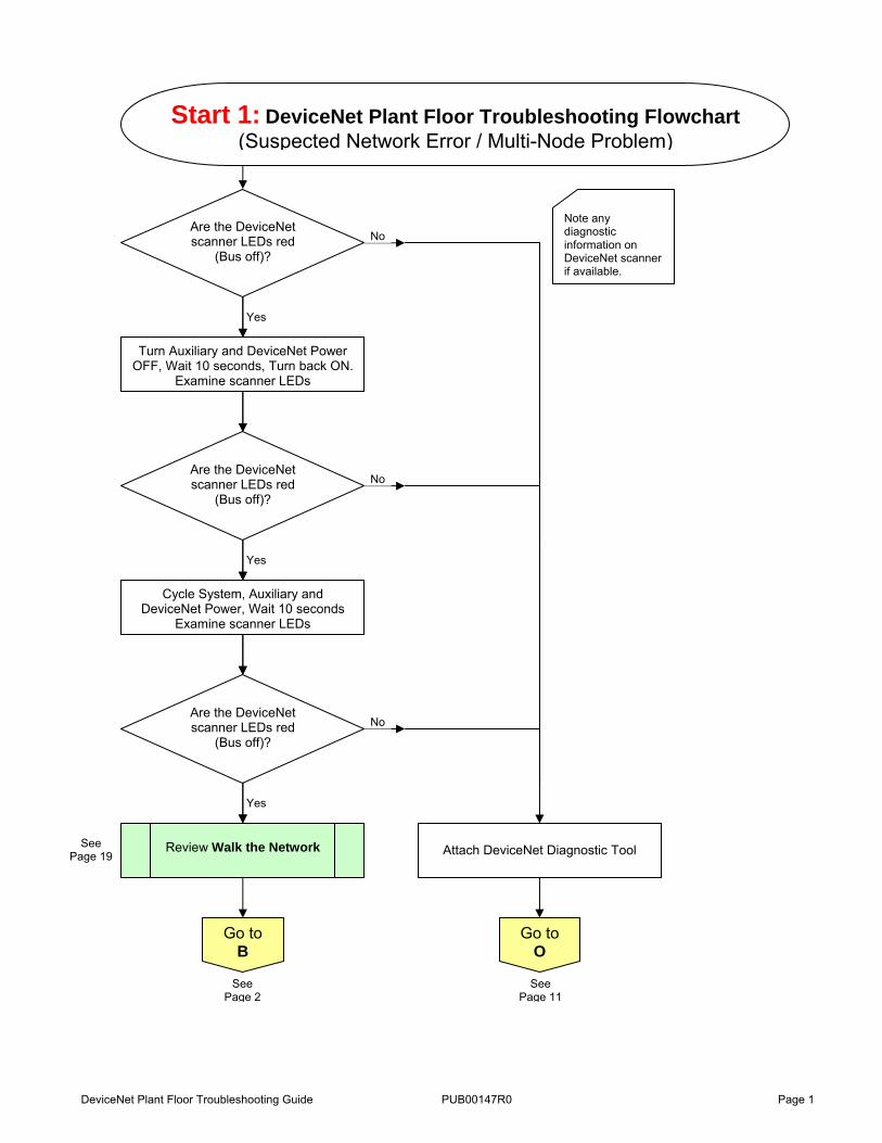
Go to D Done
B
Yes
Are there multiple DeviceNet network
power supplies? No
No
Was problem found during the network walk?
Yes
No
Are the DeviceNet scanner LEDs red
(Bus off)? Yes
Disconnect supplemental power supplies.
No
Is there only one node with red Module (MS)
or Network Status (NS) LEDs?
Yes
Go to C
Done
Check nodes and cabling inside cabinet.
Go to F
Go to E
Disconnect DeviceNet trunk cable from the cabinet with scanner module.
Attach terminating resistor. Turn off DeviceNet power, wait 10 seconds, turn
DeviceNet power back on. The bus off indication should be gone and diagnostics for missing nodes should be displayed.
Reconnect network.
No
Problem fixed?
Yes
See Page 4
See Page 3
See Page 5
See Page 3

DeviceNet Plant Floor Troubleshooting Guide PUB00147R0 Page 3
No
Is V- of the power supplies tied to V- of
DeviceNet? Yes
Wire V- of all power supplies together. Reconnect trunk cable.
C
No
Are the nodes and cables okay?
Yes
Replace cable or node.
Go to F
D
Start
Replace scanner.
Go To Start 1
Reconnect network. Reconnect network.
No
Is V+ of the power supplies wired
separately? Yes
Wire V+ of all power supplies separately.
Reconnect trunk cable.
Go to Start 1
See Page 5
See Page 1
See Page 1

DeviceNet Plant Floor Troubleshooting Guide PUB00147R0 Page 4
Disconnect node from network. Turn Auxiliary and DeviceNet Power
OFF, Wait 10 seconds, Turn back ON.
E
Note: Other nodes can cause a node to go offline.
Yes
Are the DeviceNet scanner LEDs red
(Bus off)? No
Yes
Are the DeviceNet scanner LEDs red
(Bus off)? No
Replace node. Verify Baud Rate, Node Address and
.EDS file information.
Replace drop cable.
Done
Go to F
See Page 5

DeviceNet Plant Floor Troubleshooting Guide PUB00147R0 Page 5
F
No
Have any changes been made to network since last time worked
consistently?
Yes
Investigate changes
Go to KNo
Are DeviceNet voltages correct? Yes
Change power supply
Check Voltages See Items 12, 13 & 14 in
DeviceNet Network Checklist
Go to G
Note: Changes such as cabling, tools, firmware, nodes, etc.
Go to Start 1
See Page 1
See Page 6
See Page 8
See Page 23

DeviceNet Plant Floor Troubleshooting Guide PUB00147R0 Page 6
No
Bus off condition fixed? Yes
Done
G
Complete DeviceNet Network
Checklist
No
Errors found and fixed? Yes
Done
No
Voltages OK? Yes
Go To H
Go to I
Note: This will now take some time. Check 1. Cables, 2. Node, 3. Segment, 4. Grounding 5. CAN transceiver shorted 6. Not 60Ω etc.
Check Voltages See Items 12, 13 & 14 in
DeviceNet Network Checklist
See Page 7
See Page 7
See Page 23
See Page 21

DeviceNet Plant Floor Troubleshooting Guide PUB00147R0 Page 7
Yes
All cable connections OK? No
Fix cable connection
H
I
Attach DeviceNet diagnostic tool and measure CAN errors
Yes
> 20 errors/second? No
Go to Start 1
Recheck for ground loops using
DeviceNet Network Checklist
Go to K
No
Problem found and
fixed? Yes
Go to J
Done
See Page 1
See Page 8
See Page 8
See Page 21

DeviceNet Plant Floor Troubleshooting Guide PUB00147R0 Page 8
Replace power supply again in the case that current power supply is also
bad.
J
No
Errors found and
fixed? Yes
Done
Divide network into two sections. Connect section 1 and move
terminating resistor.
Yes
Network up? No
Disconnect Section 1. Connect Section 2 and move terminating
resistor.
Yes
Network up? No
Isolate problem
Troubleshoot other ½ of the network
K
Go to L
Go to M
See Page 9
See Page 9

DeviceNet Plant Floor Troubleshooting Guide PUB00147R0 Page 9
L
Replace scanner. Reconnect entire
network.
No
Bus off condition fixed? Yes
Done
Isolate problem Check for issues in cabinet
Rewalk network looking for stressed cables (e.g. bend radius too tight, tie
wrapped where it causes failure)
No
Any shorts or opens? Yes Fix problem
Go to Start 1Go to
N
Checking for potential network load issues.
Check for wiring and other nodes within the scanner cabinet.
No
Problem Solved Yes
M
See Page 1
See Page 10

DeviceNet Plant Floor Troubleshooting Guide PUB00147R0 Page 10
N
Disconnect all nodes, add one node at a time until network communication
fails. Determine node that causes bus off and replace
Yes
Still bus off? No
Done
GET HELP

DeviceNet Plant Floor Troubleshooting Guide PUB00147R0 Page 11
Connect tool to diagnose bus. (Monitor voltages, CAN frame errors,
etc.)
Yes
Problem diagnosed? No
Fix problem indicated
Yes
Problem fixed? No
Start 2: DeviceNet Plant Floor Troubleshooting Flowchart (Intermittent Failures)
Yes
Do you have a DeviceNet
diagnostic tool? No
Go to P
Done
O
See Page 12

DeviceNet Plant Floor Troubleshooting Guide PUB00147R0 Page 12
P
Check noisy device’s grounding
Yes
Does problem occur with noise (from external
device or event)?
No
Yes
Problem fixed?
No
No
Is the device’s grounding correct? Yes
Go to Q
VFD load dumps, Servos enabled, Welding, Other Maintenance in the Area (External to Network), etc.
Fix grounding
Done
Go to R
Grounding problem
See Page 14
See Page 13

DeviceNet Plant Floor Troubleshooting Guide PUB00147R0 Page 13
Yes
Is there a noisy device on
DeviceNet? No
Q
Replace DeviceNet interface card on that device
Yes
Problem fixed?
No
Done Call Manufacturer
Go to R
e.g. VFD, Welding, Robot, Motor etc.
See Page 14

DeviceNet Plant Floor Troubleshooting Guide PUB00147R0 Page 14
Fix grounds.
R
No
Grounds OK? Yes
Check DeviceNet grounds (missing grounds or ground loops).
Yes
Problem fixed?
No
Done Go to
F
See Page 5

DeviceNet Plant Floor Troubleshooting Guide PUB00147R0 Page 15
Turn Auxiliary and DeviceNet Power OFF, Wait 10 seconds, Turn back ON.
Verify scanner is functioning.
Yes
Is the device’s Network Status
LED on solid red? No
Unplug device and check DeviceNet power and Auxiliary power at the node
Yes
Voltages OK? No
Start 3: DeviceNet Plant Floor Troubleshooting Flowchart (Node Problem)
No
Yes
Go to S
Done
Go to V
Find and fix voltage problem
Go to Start 3
Yes
Is the Device’s Network Status
LED solid green?No
Go to V
If this is your third time through this process, consider the possibility that this is a network issue rather than a node issue.
See Page 17
See Above
See Page 17
See Page 16
Is the Device’s Network Status LED
flashing or solid green?

DeviceNet Plant Floor Troubleshooting Guide PUB00147R0 Page 16
Yes
Is the device’s Net Status LED on
solid red? No
S
Verify node address and data rate. If no changes required, replace node. Be sure that node address, data rate and .EDS
revision are correct.
Yes
No
Possible cable, tee or other node that is causing the problem
Unplug node Connect DeviceNet diagnostic tool
Go to Start 3
Replace drop cable or tee
Go to Start 3
Disconnect DeviceNet diagnostic tool reconnect node. Disconnect adjacent nodes. Turn Auxiliary and DeviceNet Power OFF, Wait 10 seconds, Turn
back ON.
Yes
Can you see other nodes on the
network? No
Go to T
Go to U
Is the device’s Network Status LED
on solid green?
See Page 15
See Page 15
See Page 17
See Page 17

DeviceNet Plant Floor Troubleshooting Guide PUB00147R0 Page 17
T
One of the adjacent nodes may be causing the problem. Replace bad
node. Reconnect nodes one at a time to confirm which node is causing the
problem.
No
Was corrective action successful?
Yes
U
Disconnect nodes until the device’s Net Status LED is on solid green.
Go to Start 3
Reconnect nodes one at a time to confirm which node is causing the
problem.
Go to Start 3
V If the node’s Net Status LED is flashing green, it is ready to establish communication.
Check HMI or scanner for diagnostic information for corrective action.
Done
Walk the network and check connections.
Go to W
Replace offending node.
Reset power after removal of each node to determine if problem has
been corrected.
See Page 15
See Page 15
See Page 18

DeviceNet Plant Floor Troubleshooting Guide PUB00147R0 Page 18
W
No
Problem found and fixed?
Yes
Replace node
No
Node online? Yes
Replace drop cable or tee
Done No
Node online? Yes
Go to U
See Page 17
DeviceNet Plant Floor Troubleshooting Guide PUB00147R0 Page 19
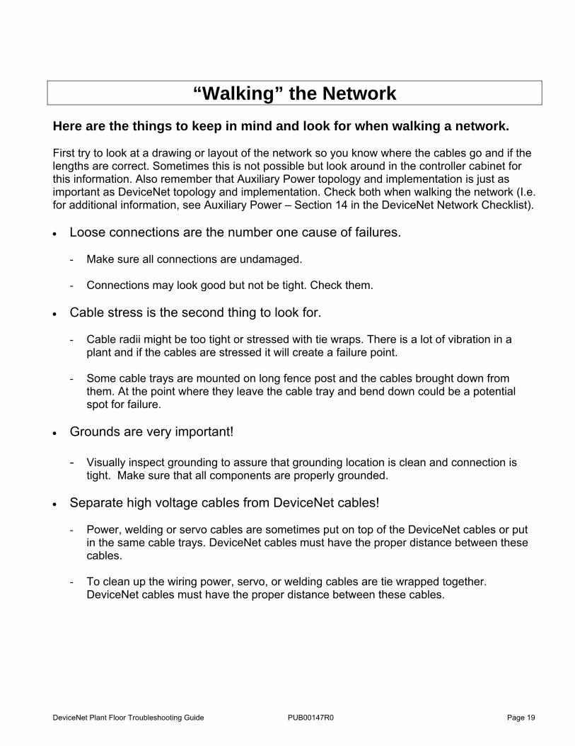
“Walking” the Network Here are the things to keep in mind and look for when walking a network. First try to look at a drawing or layout of the network so you know where the cables go and if the lengths are correct. Sometimes this is not possible but look around in the controller cabinet for this information. Also remember that Auxiliary Power topology and implementation is just as important as DeviceNet topology and implementation. Check both when walking the network (I.e. for additional information, see Auxiliary Power – Section 14 in the DeviceNet Network Checklist). • Loose connections are the number one cause of failures.
- Make sure all connections are undamaged. - Connections may look good but not be tight. Check them.
• Cable stress is the second thing to look for.
- Cable radii might be too tight or stressed with tie wraps. There is a lot of vibration in a plant and if the cables are stressed it will create a failure point.
- Some cable trays are mounted on long fence post and the cables brought down from
them. At the point where they leave the cable tray and bend down could be a potential spot for failure.
• Grounds are very important!
- Visually inspect grounding to assure that grounding location is clean and connection is tight. Make sure that all components are properly grounded.
• Separate high voltage cables from DeviceNet cables!
- Power, welding or servo cables are sometimes put on top of the DeviceNet cables or put in the same cable trays. DeviceNet cables must have the proper distance between these cables.
- To clean up the wiring power, servo, or welding cables are tie wrapped together.
DeviceNet cables must have the proper distance between these cables.

DeviceNet Plant Floor Troubleshooting Guide PUB00147R0 Page 20
Segmenting a network to troubleshoot a problem. Finding a network cable problem is sometimes not the easiest thing to detect. The following step-by-step process will assist in locating cabling issues: • Divide the network into two halves to determine which half is causing the trouble by
physically disconnecting the trunk cable and placing the terminating resistor at the break point
• Once you determine the half causing the trouble you can approach the problem two ways.
− Continue to divide the defective portion of the network in half to further isolate the trouble; or
− Re-walk the network making sure that all connections are still “OK” .If everything looks
“OK” then start at the controller and go to the first drop. Break the trunk cable and insert a terminator. Walk the terminator down the trunk until the network fails.
Once the problem location has been determined, consider the following cable connection / details as possible causes of the problem:
− Tee Connection − Drop Connection − Node Connection − Loading problem with a node or insufficient bus power. (A volt-amp-meter should be
used to determine if the problem is related to bus loading). If the network has been running and then fails, it is often due to a bad cable or “Tee” connection. Remember: There could be one or more causes for a specific problem. Take your time and check thoroughly to minimize the possibility of missing something.
Cell Number : Percent Complete: Tool Number : Station Number :
Design Source ___________________________________ Controls Engineer ______________________________
Design Engineer _________________________________ Date ______________________________
DeviceNet Plant Floor Troubleshooting Guide – DeviceNet Check List PUB00147R0 Page 21
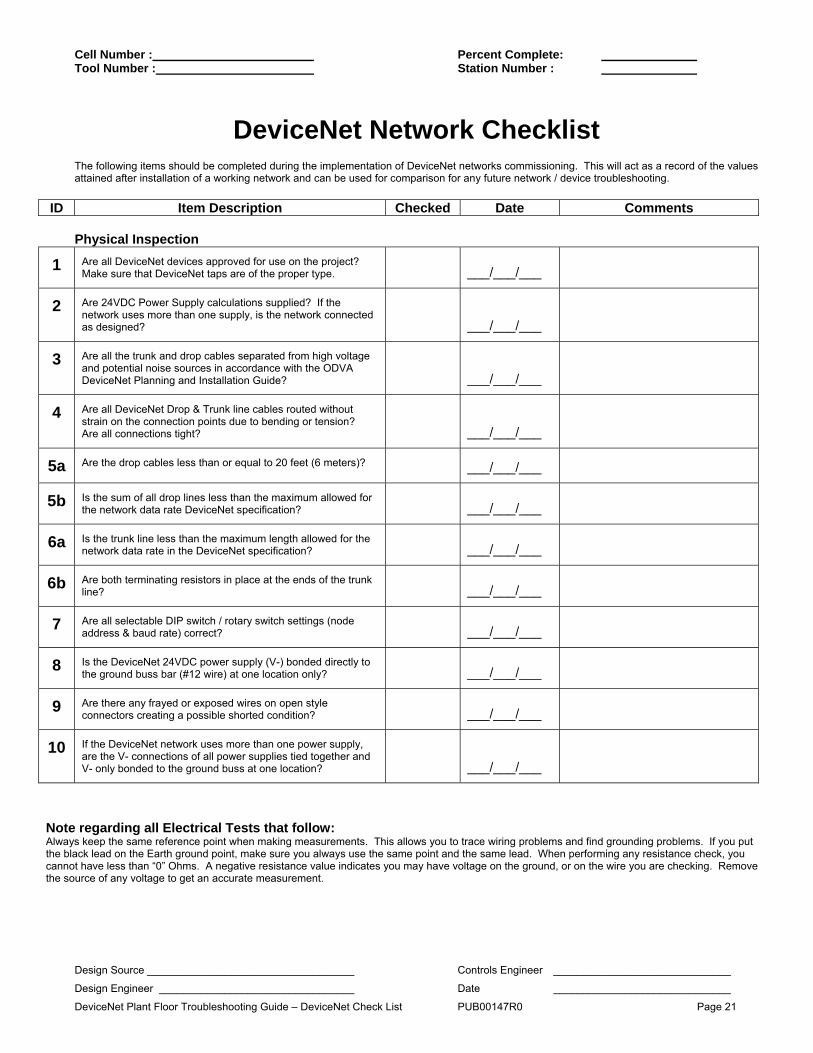
DeviceNet Network Checklist The following items should be completed during the implementation of DeviceNet networks commissioning. This will act as a record of the values attained after installation of a working network and can be used for comparison for any future network / device troubleshooting.
ID Item Description Checked Date Comments Physical Inspection
1 Are all DeviceNet devices approved for use on the project? Make sure that DeviceNet taps are of the proper type.
___/___/___
2 Are 24VDC Power Supply calculations supplied? If the network uses more than one supply, is the network connected as designed?
___/___/___
3 Are all the trunk and drop cables separated from high voltage and potential noise sources in accordance with the ODVA DeviceNet Planning and Installation Guide?
___/___/___
4 Are all DeviceNet Drop & Trunk line cables routed without strain on the connection points due to bending or tension? Are all connections tight?
___/___/___
5a Are the drop cables less than or equal to 20 feet (6 meters)? ___/___/___
5b Is the sum of all drop lines less than the maximum allowed for the network data rate DeviceNet specification?
___/___/___
6a Is the trunk line less than the maximum length allowed for the network data rate in the DeviceNet specification?
___/___/___
6b Are both terminating resistors in place at the ends of the trunk line?
___/___/___
7 Are all selectable DIP switch / rotary switch settings (node address & baud rate) correct?
___/___/___
8 Is the DeviceNet 24VDC power supply (V-) bonded directly to the ground buss bar (#12 wire) at one location only?
___/___/___
9 Are there any frayed or exposed wires on open style connectors creating a possible shorted condition?
___/___/___
10 If the DeviceNet network uses more than one power supply, are the V- connections of all power supplies tied together and V- only bonded to the ground buss at one location?
___/___/___
Note regarding all Electrical Tests that follow: Always keep the same reference point when making measurements. This allows you to trace wiring problems and find grounding problems. If you put the black lead on the Earth ground point, make sure you always use the same point and the same lead. When performing any resistance check, you cannot have less than “0” Ohms. A negative resistance value indicates you may have voltage on the ground, or on the wire you are checking. Remove the source of any voltage to get an accurate measurement.
Cell Number : Percent Complete: Tool Number : Station Number :
Design Source ___________________________________ Controls Engineer ______________________________
Design Engineer _________________________________ Date ______________________________
DeviceNet Plant Floor Troubleshooting Guide – DeviceNet Check List PUB00147R0 Page 22
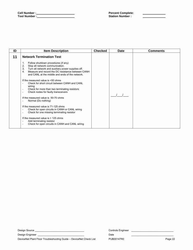
ID Item Description Checked Date Comments
11
Network Termination Test 1. Follow shutdown procedures (if any) 2. Stop all network communication. 3. Turn all network and auxiliary power supplies off. 4. Measure and record the DC resistance between CANH
and CANL at the middle and ends of the network. If the measured value is <50 ohms - Check for short circuit between CANH and CANL
wiring - Check for more than two terminating resistors - Check nodes for faulty transceivers If the measured value is 50-70 ohms - Normal (Do nothing) If the measured value is 71-125 ohms - Check for open circuits in CANH or CANL wiring - Check for one missing terminating resistor If the measured value is > 125 ohms - Add terminating resistor - Check for open circuits in CANH and CANL wiring
___/___/___
Cell Number : Percent Complete: Tool Number : Station Number :
Design Source ___________________________________ Controls Engineer ______________________________
Design Engineer _________________________________ Date ______________________________
DeviceNet Plant Floor Troubleshooting Guide – DeviceNet Check List PUB00147R0 Page 23
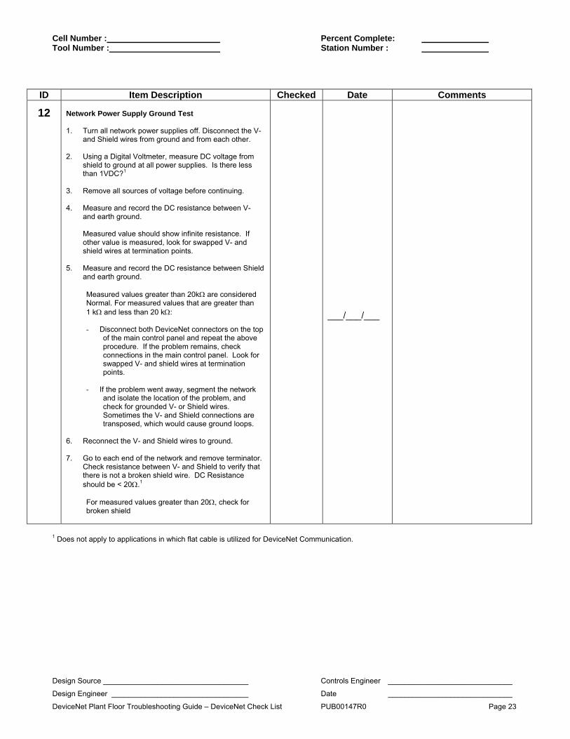
ID Item Description Checked Date Comments
12 Network Power Supply Ground Test 1. Turn all network power supplies off. Disconnect the V-
and Shield wires from ground and from each other. 2. Using a Digital Voltmeter, measure DC voltage from
shield to ground at all power supplies. Is there less than 1VDC?1
3. Remove all sources of voltage before continuing. 4. Measure and record the DC resistance between V-
and earth ground.
Measured value should show infinite resistance. If other value is measured, look for swapped V- and shield wires at termination points.
5. Measure and record the DC resistance between Shield
and earth ground.
Measured values greater than 20kΩ are considered Normal. For measured values that are greater than 1 kΩ and less than 20 kΩ: - Disconnect both DeviceNet connectors on the top
of the main control panel and repeat the above procedure. If the problem remains, check connections in the main control panel. Look for swapped V- and shield wires at termination points.
- If the problem went away, segment the network
and isolate the location of the problem, and check for grounded V- or Shield wires. Sometimes the V- and Shield connections are transposed, which would cause ground loops.
6. Reconnect the V- and Shield wires to ground. 7. Go to each end of the network and remove terminator.
Check resistance between V- and Shield to verify that there is not a broken shield wire. DC Resistance should be < 20Ω.1
For measured values greater than 20Ω, check for broken shield
___/___/___
1 Does not apply to applications in which flat cable is utilized for DeviceNet Communication.

Cell Number : Percent Complete: Tool Number : Station Number :
Design Source ___________________________________ Controls Engineer ______________________________
Design Engineer _________________________________ Date ______________________________
DeviceNet Plant Floor Troubleshooting Guide – DeviceNet Check List PUB00147R0 Page 24
ID Item Description Checked Date Comments
13 Network Power Supply Common Mode Voltage Test 1. Turn all network power supplies on. 2. Configure all nodes for their maximum current draw
from network power. Turn on outputs that use network power.
3. Measure and record the DC voltage between V+ and
V- where each power supply connects to the trunk. 4. Measure and record the DC voltage between V+ and
V- at the ends of the network.
Measured values between 11.0 VDC and 25.0 VDC are consistent with the DeviceNet Specification for proper DeviceNet communication. However, input devices that may rely V+ and V- for power may not operate properly at voltages less than 20 VDC. Check input device (e.g. proximity sensors, photoelectric sensors, etc.) to verify device is within voltage specifications.
5. Measure between V- and Shield. Measured values
less than 4.6 VDC are considered normal.
If measured value from: Item 4. Is < 11.0 VDC; or Item 5. Is > 4.6 VDC,
The network may not operate properly. Possible solutions are :
- Shorten the overall length of the network cable. - Move the power supply in the direction of the
overloaded section. - Move nodes from the overload section to less loaded
section. - Move high current loads close to the power supply. - Break the network into two separate networks. - Add power supply.
___/___/___

Cell Number : Percent Complete: Tool Number : Station Number :
Design Source ___________________________________ Controls Engineer ______________________________
Design Engineer _________________________________ Date ______________________________
DeviceNet Plant Floor Troubleshooting Guide – DeviceNet Check List PUB00147R0 Page 25
ID Item Description Checked Date Comments
14 Auxiliary Power Measurements 1. Monitor the voltage present at both ends of the
auxiliary power trunk cable under normal operating conditions and record the high and low values observed. The use of an oscilloscope may be necessary.
2. Check all manufacturers’ specifications to verify that
the auxiliary power observed falls within the manufacturers’ specifications.
If problems are observed, consider the following - Add an additional power supply - Shorten auxiliary power trunk line cabling - Check for influence of noise - Assure that the grounding requirements outlined
in the manufacturers’ specifications have been met.
___/___/___