PTP 820G Technical Description
236
Cambium PTP 820G Technical Description System Release 7.9 phn-3968 001v000
-
Upload
zeljko-m-boskovic -
Category
Documents
-
view
67 -
download
1
description
Cambium PTP820 G Technical Description
Transcript of PTP 820G Technical Description

Cambium
PTP 820G
Technical Description
System Release 7.9
phn-3968 001v000

phn-3968 001v000
Accuracy
While reasonable efforts have been made to assure the accuracy of this document, Cambium Networks
assumes no liability resulting from any inaccuracies or omissions in this document, or from use of the
information obtained herein. Cambium reserves the right to make changes to any products described
herein to improve reliability, function, or design, and reserves the right to revise this document and to
make changes from time to time in content hereof with no obligation to notify any person of revisions
or changes. Cambium does not assume any liability arising out of the application or use of any
product, software, or circuit described herein; neither does it convey license under its patent rights or
the rights of others. It is possible that this publication may contain references to, or information about
Cambium products (machines and programs), programming, or services that are not announced in
your country. Such references or information must not be construed to mean that Cambium intends to
announce such Cambium products, programming, or services in your country.
Copyrights
This document, Cambium products, and 3rd Party software products described in this document may
include or describe copyrighted Cambium and other 3rd Party supplied computer programs stored in
semiconductor memories or other media. Laws in the United States and other countries preserve for
Cambium, its licensors, and other 3rd Party supplied software certain exclusive rights for copyrighted
material, including the exclusive right to copy, reproduce in any form, distribute and make derivative
works of the copyrighted material. Accordingly, any copyrighted material of Cambium, its licensors, or
the 3rd Party software supplied material contained in the Cambium products described in this
document may not be copied, reproduced, reverse engineered, distributed, merged or modified in any
manner without the express written permission of Cambium. Furthermore, the purchase of Cambium
products shall not be deemed to grant either directly or by implication, estoppel, or otherwise, any
license under the copyrights, patents or patent applications of Cambium or other 3rd Party supplied
software, except for the normal non-exclusive, royalty free license to use that arises by operation of
law in the sale of a product.
Restrictions
Software and documentation are copyrighted materials. Making unauthorized copies is prohibited by
law. No part of the software or documentation may be reproduced, transmitted, transcribed, stored in a
retrieval system, or translated into any language or computer language, in any form or by any means,
without prior written permission of Cambium.
License Agreements
The software described in this document is the property of Cambium and its licensors. It is furnished
by express license agreement only and may be used only in accordance with the terms of such an
agreement.
High Risk Materials
Cambium and its supplier(s) specifically disclaim any express or implied warranty of fitness for any
high risk activities or uses of its products including, but not limited to, the operation of nuclear
facilities, aircraft navigation or aircraft communication systems, air traffic control, life support, or
weapons systems (“High Risk Use”). Any High Risk is unauthorized, is made at your own risk and you
shall be responsible for any and all losses, damage or claims arising out of any High Risk Use.
© 2014 Cambium Networks Limited. All Rights Reserved.

phn-3968 001v000
Page i
Contents
About This User Guide......................................................................................................................1
Contacting Cambium Networks .................................................................................................. 1
Purpose ......................................................................................................................................... 2
Cross references ........................................................................................................................... 2
Feedback ....................................................................................................................................... 2
Problems and warranty ...................................................................................................................... 3
Reporting problems ..................................................................................................................... 3
Repair and service ........................................................................................................................ 3
Hardware warranty ...................................................................................................................... 3
Security advice .................................................................................................................................... 4
Warnings, cautions, and notes........................................................................................................... 5
Warnings ....................................................................................................................................... 5
Cautions ........................................................................................................................................ 5
Notes ............................................................................................................................................. 5
Caring for the environment ................................................................................................................ 6
In EU countries ............................................................................................................................. 6
In non-EU countries ..................................................................................................................... 6
Chapter 1: Product description ................................................................................................... 1-1
Product Overview ............................................................................................................................. 1-2
PTP 820G Radio Options ........................................................................................................... 1-3
PTP 820G Highlights ................................................................................................................. 1-3
PTP 820G Protection Options ................................................................................................... 1-4
Chapter 2: Hardware Description ............................................................................................... 2-1
Hardware Architecture ..................................................................................................................... 2-2
Front Panel Description ................................................................................................................... 2-3
Ethernet Traffic Interfaces ............................................................................................................... 2-4
Ethernet Management Interfaces .................................................................................................... 2-6
DS1/E1 Interface (Optional) ............................................................................................................. 2-8
Radio Interfaces................................................................................................................................ 2-9
Power Interfaces ............................................................................................................................. 2-11
Synchronization Interface .............................................................................................................. 2-12
Terminal Interface .......................................................................................................................... 2-13
Unit/ACT LED .................................................................................................................................. 2-14
External Alarms .............................................................................................................................. 2-15
Chapter 3: RFU Overview ........................................................................................................... 3-1
RFU-C ................................................................................................................................................ 3-2
Main Features of RFU-C ............................................................................................................ 3-2

Contents
phn-3968 001v000
Page ii
Chapter 4: Activation Keys ......................................................................................................... 4-1
Working with Activation Keys ......................................................................................................... 4-2
Demo Mode License ........................................................................................................................ 4-3
Activation Key-Enabled Features .................................................................................................... 4-4
Chapter 5: Feature Description ................................................................................................... 5-1
Innovative Techniques to Boost Capacity and Reduce Latency ................................................... 5-2
Capacity Summary .................................................................................................................... 5-2
Header De-Duplication .............................................................................................................. 5-3
Latency ....................................................................................................................................... 5-5
Frame Cut-Through ................................................................................................................... 5-5
Radio Features.................................................................................................................................. 5-8
Adaptive Coding Modulation (ACM) ........................................................................................ 5-8
Cross Polarization Interference Canceller (XPIC) .................................................................. 5-11
1+1 HSB Radio Protection ....................................................................................................... 5-13
ATPC ......................................................................................................................................... 5-15
Multi-Carrier ABC .................................................................................................................... 5-16
BBS Space Diversity ................................................................................................................ 5-18
Radio Utilization PMs .............................................................................................................. 5-19
Ethernet Features ........................................................................................................................... 5-20
Ethernet Services Overview ................................................................................................... 5-20
PTP 820G’s Ethernet Capabilities ........................................................................................... 5-35
Supported Standards .............................................................................................................. 5-36
Ethernet Service Model .......................................................................................................... 5-36
Ethernet Interfaces .................................................................................................................. 5-51
Quality of Service (QoS) ......................................................................................................... 5-60
Global Switch Configuration .................................................................................................. 5-86
Network Resiliency .................................................................................................................. 5-86
OAM ......................................................................................................................................... 5-91
Synchronization ............................................................................................................................. 5-95
Synchronization Overview...................................................................................................... 5-95
PTP 820G Synchronization Solution ...................................................................................... 5-98
Available Synchronization Interfaces .................................................................................... 5-98
Configuring Native Sync Distribution .................................................................................... 5-99
Native Sync Distribution Mode ............................................................................................ 5-100
SyncE PRC Pipe Regenerator Mode ..................................................................................... 5-104
SSM Support and Loop Prevention ..................................................................................... 5-105
TDM Services ............................................................................................................................... 5-106
Native TDM Trails .................................................................................................................. 5-107
TDM Pseudowire ................................................................................................................... 5-110
Chapter 6: PTP 820G Management ............................................................................................ 6-1
Management Overview ................................................................................................................... 6-2
Automatic Network Topology Discovery with LLDP Protocol ...................................................... 6-3
IPv6 Support ..................................................................................................................................... 6-4

Contents
phn-3968 001v000
Page iii
Management Communication Channels and Protocols ............................................................... 6-5
Web-Based Element Management System (Web EMS) ......................................................... 6-7
Command Line Interface (CLI)......................................................................................................... 6-8
Configuration Management ............................................................................................................ 6-9
Software Management .................................................................................................................. 6-10
Backup Software Version ....................................................................................................... 6-10
In-Band Management ............................................................................................................. 6-11
Local Management .................................................................................................................. 6-11
Alarms ............................................................................................................................................. 6-12
Configurable RSL Threshold Alarms and Traps ................................................................... 6-12
Alarms Editing ......................................................................................................................... 6-12
External Alarms .............................................................................................................................. 6-13
NTP Support ................................................................................................................................... 6-14
UTC Support .................................................................................................................................... 6-15
System Security Features .............................................................................................................. 6-16
Cambium’s Layered Security Concept ......................................................................................... 6-17
Defenses in Management Communication Channels .......................................................... 6-17
Defenses in User and System Authentication Procedures .................................................. 6-18
Secure Communication Channels .......................................................................................... 6-21
Security Log ............................................................................................................................. 6-23
Chapter 7: Standards and Certifications ..................................................................................... 7-1
Supported Ethernet Standards ....................................................................................................... 7-2
Supported TDM Pseudowire Encapsulations ................................................................................ 7-3
Standards Compliance .................................................................................................................... 7-4
Network Management, Diagnostics, Status, and Alarms ............................................................. 7-5
Chapter 8: Specifcations ............................................................................................................ 8-1
Radio Specifications ........................................................................................................................ 8-2
General Specifications .............................................................................................................. 8-2
Capacity Specifications ............................................................................................................. 8-4
Transmit Power Specifications (dBm) ................................................................................... 8-13
Receiver Threshold (RSL) Specifications (dBm @ BER = 10-6) ........................................... 8-14
Frequency Bands ..................................................................................................................... 8-18
Network Specifications .................................................................................................................. 8-30
Ethernet Latency Specifications ............................................................................................. 8-30
Ethernet Specifications ........................................................................................................... 8-34
Synchronization Specifications .............................................................................................. 8-35
Power Specifications ..................................................................................................................... 8-36
Power Input Specifications ..................................................................................................... 8-36
Power Consumption Specifications ....................................................................................... 8-36
Physical and Electrical Specifications ........................................................................................... 8-37
Mediation Device Losses ........................................................................................................ 8-37
TDM Specifications ................................................................................................................. 8-37
Mechanical Specifications ...................................................................................................... 8-38

Contents
phn-3968 001v000
Page iv
Environmental Specifications................................................................................................. 8-39
Supported Antenna Types ...................................................................................................... 8-39
Glossary ............................................................................................................................................ I
Figures Figure 1 PTP 820G Block Diagram ....................................................................................................... 2-2
Figure 2 PTP 820G Front Panel and Interfaces .................................................................................... 2-3
Figure 3 Electrical GE Interface LEDs ................................................................................................... 2-4
Figure 4 Optical GE Interface LED ........................................................................................................ 2-5
Figure 5 Management Interface Pin Connections ............................................................................... 2-6
Figure 6 Management FE Interface LEDs ............................................................................................ 2-7
Figure 7 TDM Interface LEDs ................................................................................................................ 2-8
Figure 8 Radio Interface LEDs ............................................................................................................ 2-10
Figure 9 Power Interface LEDs ........................................................................................................... 2-11
Figure 10 Sync Interface LEDs ............................................................................................................ 2-12
Figure 11 Unit/ACT LED ...................................................................................................................... 2-14
Figure 12 Header De-Duplication ......................................................................................................... 5-3
Figure 13 Header De-Duplication Potential Throughput Savings per Layer ..................................... 5-4
Figure 14 Propagation Delay with and without Frame Cut-Through ................................................ 5-6
Figure 15 Frame Cut-Through .............................................................................................................. 5-6
Figure 16 Frame Cut-Through Operation ............................................................................................ 5-7
Figure 17 Adaptive Coding and Modulation with 10 Working Points ............................................... 5-9
Figure 18 Dual Polarization ................................................................................................................. 5-12
Figure 19 XPIC Implementation ......................................................................................................... 5-12
Figure 20 XPIC – Impact of Misalignments and Channel Degradation ........................................... 5-13
Figure 21 Path Loss on Secondary Path of 1+1 HSB Protection Link .............................................. 5-14
Figure 22 Multi-Carrier ABC Traffic Flow........................................................................................... 5-16
Figure 23 Direct and Reflected Signals .............................................................................................. 5-18
Figure 24 1+1 BBS Space Diversity Configuration – Receiving Side ............................................... 5-19
Figure 25 Basic Ethernet Service Model ............................................................................................ 5-21
Figure 26 Ethernet Virtual Connection (EVC) .................................................................................... 5-21
Figure 27 Point to Point EVC .............................................................................................................. 5-22
Figure 28 Multipoint to Multipoint EVC ............................................................................................. 5-22
Figure 29 Rooted Multipoint EVC ....................................................................................................... 5-23
Figure 30 MEF Ethernet Services Definition Framework.................................................................. 5-24
Figure 31 E-Line Service Type Using Point-to-Point EVC ................................................................. 5-26
Figure 32 EPL Application Example ................................................................................................... 5-26
Figure 33 EVPL Application Example................................................................................................. 5-27
Figure 34 E-LAN Service Type Using Multipoint-to-Multipoint EVC ............................................... 5-27
Figure 35 Adding a Site Using an E-Line service .............................................................................. 5-28
Figure 36 Adding a Site Using an E-LAN service .............................................................................. 5-28

Contents
phn-3968 001v000
Page v
Figure 37 MEF Ethernet Private LAN Example .................................................................................. 5-29
Figure 38 MEF Ethernet Virtual Private LAN Example...................................................................... 5-30
Figure 39 E-Tree Service Type Using Rooted-Multipoint EVC ......................................................... 5-30
Figure 40 E-Tree Service Type Using Multiple Roots ....................................................................... 5-31
Figure 41 MEF Ethernet Private Tree Example ................................................................................. 5-31
Figure 42 Ethernet Virtual Private Tree Example .............................................................................. 5-32
Figure 43 Mobile Backhaul Reference Model .................................................................................... 5-33
Figure 44 Packet Service Core Building Blocks ................................................................................. 5-33
Figure 45 PTP 820G Services Model .................................................................................................. 5-36
Figure 46 PTP 820G Services Core ..................................................................................................... 5-37
Figure 47 PTP 820G Services Flow .................................................................................................... 5-38
Figure 48 Point-to-Point Service ........................................................................................................ 5-39
Figure 49 Multipoint Service .............................................................................................................. 5-40
Figure 50 Management Service ......................................................................................................... 5-42
Figure 51 Management Service and its Service Points .................................................................... 5-44
Figure 52 SAPs and SNPs ................................................................................................................... 5-45
Figure 53 Pipe Service Points ............................................................................................................. 5-45
Figure 54 SAP, SNP and Pipe Service Points in a Microwave Network .......................................... 5-46
Figure 55 Service Path Relationship on Point-to-Point Service Path............................................... 5-50
Figure 56 Physical and Logical Interfaces ......................................................................................... 5-52
Figure 57 Grouped Interfaces as a Single Logical Interface on Ingress Side ................................. 5-53
Figure 58 Grouped Interfaces as a Single Logical Interface on Egress Side .................................. 5-53
Figure 59 Relationship of Logical Interfaces to the Switching Fabric ............................................. 5-56
Figure 60 QoS Block Diagram ............................................................................................................ 5-61
Figure 61 Standard QoS and H-QoS Comparison ............................................................................ 5-62
Figure 62 Hierarchical Classification .................................................................................................. 5-63
Figure 63 Classification Method Priorities......................................................................................... 5-64
Figure 64 Ingress Policing Model ....................................................................................................... 5-68
Figure 65 PTP 820G Queue Manager ................................................................................................. 5-71
Figure 66 Synchronized Packet Loss ................................................................................................. 5-72
Figure 67 Random Packet Loss with Increased Capacity Utilization Using WRED ........................ 5-73
Figure 68 WRED Profile Curve ............................................................................................................ 5-74
Figure 69 Detailed H-QoS Diagram .................................................................................................... 5-77
Figure 70 Scheduling Mechanism for a Single Service Bundle ....................................................... 5-80
Figure 71 G.8032 Ring in Idle (Normal) State .................................................................................... 5-88
Figure 72 G.8032 Ring in Protecting State......................................................................................... 5-88
Figure 73 Load Balancing Example in G.8032 Ring .......................................................................... 5-89
Figure 74 PTP 820G End-to-End Service Management .................................................................... 5-91
Figure 75 SOAM Maintenance Entities (Example) ............................................................................ 5-92
Figure 76 Ethernet Line Interface Loopback – Application Examples ............................................. 5-93
Figure 77 Precision Timing Protocol (PTP) Synchronization ........................................................... 5-97
Figure 78 Synchronous Ethernet (SyncE).......................................................................................... 5-97
Figure 79 Synchronization Configuration........................................................................................ 5-100

Contents
phn-3968 001v000
Page vi
Figure 80 Native Sync Distribution Mode ....................................................................................... 5-101
Figure 81 Native Sync Distribution Mode Usage Example ............................................................ 5-102
Figure 82 Native Sync Distribution Mode – Tree Scenario ............................................................ 5-103
Figure 83 Native Sync Distribution Mode – Ring Scenario (Normal Operation) .......................... 5-103
Figure 84 Native Sync Distribution Mode – Ring Scenario (Link Failure) ..................................... 5-104
Figure 85 Hybrid Ethernet and TDM Services ................................................................................. 5-106
Figure 86 Hybrid Ethernet and TDM Services Carried Over Cascading Interfaces ...................... 5-106
Figure 87 Hybrid Ethernet and Native TDM Services ..................................................................... 5-107
Figure 88 1:1 TDM Path Protection – Ring Topology ...................................................................... 5-108
Figure 89 1+1 Dual Homing TDM Path Protection – Network Topology ....................................... 5-109
Figure 90 All-Packet Ethernet and TDM Pseudowire Services ....................................................... 5-111
Figure 91 Integrated PTP 820G Management Tools ........................................................................... 6-2
Figure 92 Security Solution Architecture Concept ........................................................................... 6-17
Tables Table 1 PTP 820G Interfaces ................................................................................................................. 2-3
Table 2 PTP820 Ethernet split cable for Management........................................................................ 2-6
Table 3 Activation Key Types ............................................................................................................... 4-4
Table 4 Capacity Activation Key Levels ............................................................................................... 4-6
Table 5 CET Node Activation Key Levels............................................................................................. 4-7
Table 6 ACM Working Points (Profiles) ............................................................................................... 5-9
Table 7 MEF-Defined Ethernet Service Types ................................................................................... 5-25
Table 8 Ethernet Services Learning and Forwarding ....................................................................... 5-41
Table 9 Service Point Types per Service Type .................................................................................. 5-46
Table 10 Service Point Types that can Co-Exist on the Same Interface .......................................... 5-48
Table 11 Attached Interface Type combinations SAP ...................................................................... 5-48
Table 12 Attached Interface Type combinations SNP Pipe MNG .................................................... 5-49
Table 13 C-VLAN 802.1 UP and CFI Default Mapping to CoS and Color .......................................... 5-64
Table 14 S-VLAN 802.1 UP and DEI Default Mapping to CoS and Color ........................................ 5-65
Table 15 DSCP Default Mapping to CoS and Color .......................................................................... 5-65
Table 16 MPLS EXP Default Mapping to CoS and Color .................................................................. 5-66
Table 17 QoS Priority Profile Example - Profile ID (1-9) ................................................................... 5-81
Table 18 WFQ Profile Example - Profile ID (1-7) ............................................................................... 5-82
Table 19 802.1q UP Marking Table (C-VLAN).................................................................................... 5-84
Table 20 802.1ad UP Marking Table (S-VLAN) .................................................................................. 5-84
Table 21 Summary and Comparison of Standard QoS and H-QoS ................................................ 5-85
Table 22 Synchronization input Options ........................................................................................... 5-98
Table 23 Synchronization Output Options ........................................................................................ 5-98
Table 24 Dedicated Management Ports............................................................................................... 6-5
Table 25 NMS Server Receiving Data Ports ........................................................................................ 6-6
Table 26 Web Sending Data Ports ....................................................................................................... 6-6
Table 27 Web Receiving Data Ports ..................................................................................................... 6-7

Contents
phn-3968 001v000
Page vii
Table 28 Additional Management Ports for PTP 820G ....................................................................... 6-7
Table 29 Supported Ethernet Standards ............................................................................................. 7-2
Table 30 Supported TDM Pseudowire Encapsulations ...................................................................... 7-3
Table 31 Standards Compliancc .......................................................................................................... 7-4
Table 32 Network management, Diagnostics, Status and alarms ..................................................... 7-5
Table 33 General Radio Specifications for ANSI ................................................................................ 8-2
Table 34 General Radio Specifications for ETSI ................................................................................. 8-3
Table 35 Capacity 7 MHz Channel Bandwidth (no XPIC) .................................................................... 8-4
Table 36 Capacity 14 MHz Channel Bandwidth (no XPIC).................................................................. 8-5
Table 37 Capacity 28 MHz Channel Bandwidth (no XPIC).................................................................. 8-5
Table 38 Capacity 28 MHz Channel Bandwidth with XPIC ................................................................. 8-6
Table 39 Capacity 30 MHz Channel Bandwidth (no XPIC).................................................................. 8-7
Table 40 Capacity 30 MHz Channel Bandwidth with XPIC ................................................................. 8-8
Table 41 Capacity 40 MHz Channel Bandwidth with XPIC ................................................................. 8-8
Table 42 Capacity 40 MHz Channel Bandwidth (no XPIC).................................................................. 8-9
Table 43 Capacity 50 MHz Channel Bandwidth (no XPIC)................................................................ 8-10
Table 44 Capacity 56 MHz Channel Bandwidth (no XPIC)................................................................ 8-11
Table 45 Capacity 56 MHz Channel Bandwidth with XPIC ............................................................... 8-12
Table 46 Capacity 60 MHz Channel Bandwidth (no XPIC)................................................................ 8-12
Table 47 Transmit Power Specifications ........................................................................................... 8-13
Table 48 Receiver Threshold for 7 MHz Channel spacing ................................................................ 8-14
Table 49 Receiver Threshold for 14 MHz Channel spacing .............................................................. 8-14
Table 50 Receiver Threshold for 28 MHz Channel spacing .............................................................. 8-15
Table 51 Receiver Threshold for 30MHz Channel spacing ............................................................... 8-15
Table 52 Receiver Threshold for 40 MHz Channel spacing .............................................................. 8-16
Table 53 Receiver Threshold for 50MHz Channel spacing ............................................................... 8-16
Table 54 Receiver Threshold for 56 MHz Channel spacing .............................................................. 8-17
Table 55 Frequency Bands ................................................................................................................. 8-18
Table 56 Ethernet Latency 7 MHz Channel Bandwidth .................................................................... 8-30
Table 57 Ethernet Latency 14 MHz Channel Bandwidth ................................................................... 8-30
Table 58 Ethernet Latency 28 MHz Channel Bandwidth ................................................................... 8-31
Table 59 Ethernet Latency 30 MHz Channel Bandwidth ................................................................... 8-32
Table 60 Ethernet Latency 40 MHz Channel Bandwidth ................................................................... 8-32
Table 61 Ethernet Latency 50 MHz Channel Bandwidth ................................................................... 8-33
Table 62 Ethernet Latency 56 MHz Channel Bandwidth ................................................................... 8-34
Table 63 Ethernet Interface Specifications ........................................................................................ 8-34
Table 64 Carrier Ethernet Functionality ............................................................................................. 8-34
Table 65 Synchronization Specifications........................................................................................... 8-35
Table 66 Power Input Specifications.................................................................................................. 8-36
Table 67 Power Consumption Specifications ................................................................................... 8-36
Table 68 RFU-C Mediation Device Losses ......................................................................................... 8-37
Table 69 DS1 Interface Specifications ............................................................................................... 8-37
Table 70 E1 Interface Specifications .................................................................................................. 8-38

Contents
phn-3968 001v000
Page viii
Table 71 IDU Mechanical Specifications ........................................................................................... 8-38
Table 72 RFU-C Mechanical Specifications ....................................................................................... 8-38

phn-3968 001v000
Page 1
About This User Guide
This guide contains the following chapters:
Chapter 1: Product description
Chapter 2: Hardware Description
Chapter 3: RFU Overview
Error! Reference source not found.Activation Keys
Chapter 5: Feature Description
Chapter 6: PTP 820G Management
Chapter 7: Standards and Certifications
Chapter 8: Specifcations
Contacting Cambium Networks
Support website: http://www.cambiumnetworks.com/support
Main website: http://www.cambiumnetworks.com
Sales enquiries: [email protected]
Support enquiries: [email protected]
Telephone number list: http://www.cambiumnetworks.com/support/contact-support
Address: Cambium Networks Limited,
Linhay Business Park,
Eastern Road,
Ashburton,
Devon, UK,
TQ13 7UP

About This User Guide Problems and warranty
phn-3968 001v000
Page 2
Purpose
Cambium Networks Point-To-Point (PTP) documents are intended to instruct and assist personnel
in the operation, installation and maintenance of the Cambium PTP equipment and ancillary
devices. It is recommended that all personnel engaged in such activities be properly trained.
Cambium disclaims all liability whatsoever, implied or express, for any risk of damage, loss or
reduction in system performance arising directly or indirectly out of the failure of the customer, or
anyone acting on the customer's behalf, to abide by the instructions, system parameters, or
recommendations made in this document.
Cross references
References to external publications are shown in italics. Other cross references, emphasized in
blue text in electronic versions, are active links to the references.
This document is divided into numbered chapters that are divided into sections. Sections are not
numbered, but are individually named at the top of each page, and are listed in the table of
contents.
Feedback
We appreciate feedback from the users of our documents. This includes feedback on the structure,
content, accuracy, or completeness of our documents. Send feedback to

About This User Guide Problems and warranty
phn-3968 001v000
Page 3
Problems and warranty
Reporting problems
If any problems are encountered when installing or operating this equipment, follow this
procedure to investigate and report:
1 Search this document and the software release notes of supported releases.
2 Visit the support website.
3 Ask for assistance from the Cambium product supplier.
4 Gather information from affected units, such as any available diagnostic downloads.
5 Escalate the problem by emailing or telephoning support.
Repair and service
If unit failure is suspected, obtain details of the Return Material Authorization (RMA) process from
the support website.
Hardware warranty
Cambium’s standard hardware warranty is for one (1) year from date of shipment from Cambium
Networks or a Cambium distributor. Cambium Networks warrants that hardware will conform to
the relevant published specifications and will be free from material defects in material and
workmanship under normal use and service. Cambium shall within this time, at its own option,
either repair or replace the defective product within thirty (30) days of receipt of the defective
product. Repaired or replaced product will be subject to the original warranty period but not less
than thirty (30) days.
To register PTP products or activate warranties, visit the support website. For warranty assistance,
contact the reseller or distributor.
Caution
Using non-Cambium parts for repair could damage the equipment or void warranty.
Contact Cambium for service and repair instructions.
Portions of Cambium equipment may be damaged from exposure to electrostatic
discharge. Use precautions to prevent damage.

About This User Guide Security advice
phn-3968 001v000
Page 4
Security advice
Cambium Networks systems and equipment provide security parameters that can be configured
by the operator based on their particular operating environment. Cambium recommends setting
and using these parameters following industry recognized security practices. Security aspects to
be considered are protecting the confidentiality, integrity, and availability of information and
assets. Assets include the ability to communicate, information about the nature of the
communications, and information about the parties involved.
In certain instances Cambium makes specific recommendations regarding security practices,
however the implementation of these recommendations and final responsibility for the security of
the system lies with the operator of the system.

About This User Guide Warnings, cautions, and notes
phn-3968 001v000
Page 5
Warnings, cautions, and notes
The following describes how warnings and cautions are used in this document and in all
documents of the Cambium Networks document set.
Warnings
Warnings precede instructions that contain potentially hazardous situations. Warnings are used to
alert the reader to possible hazards that could cause loss of life or physical injury. A warning has
the following format:
Warning
Warning text and consequence for not following the instructions in the warning.
Cautions
Cautions precede instructions and are used when there is a possibility of damage to systems,
software, or individual items of equipment within a system. However, this damage presents no
danger to personnel. A caution has the following format:
Caution
Caution text and consequence for not following the instructions in the caution.
Notes
A note means that there is a possibility of an undesirable situation or provides additional
information to help the reader understand a topic or concept. A note has the following format:
Note
Note text.

About This User Guide Caring for the environment
phn-3968 001v000
Page 6
Caring for the environment
The following information describes national or regional requirements for the disposal of
Cambium Networks supplied equipment and for the approved disposal of surplus packaging.
In EU countries
The following information is provided to enable regulatory compliance with the European Union
(EU) directives identified and any amendments made to these directives when using Cambium
equipment in EU countries.
Disposal of Cambium equipment
European Union (EU) Directive 2002/96/EC Waste Electrical and Electronic Equipment (WEEE)
Do not dispose of Cambium equipment in landfill sites. For disposal instructions, refer to
http://www.cambiumnetworks.com/support
Disposal of surplus packaging
Do not dispose of surplus packaging in landfill sites. In the EU, it is the individual recipient’s
responsibility to ensure that packaging materials are collected and recycled according to the
requirements of EU environmental law.
In non-EU countries
In non-EU countries, dispose of Cambium equipment and all surplus packaging in accordance with
national and regional regulations.

phn-3968 001v000
Page 1-1
Chapter 1: Product description
This chapter provides an overview of the PTP 820G, high-performance edge node product. PTP
820G is specially designed for edge/tail sites, and features a small footprint, high density, and a
high degree of availability.
PTP 820G is an integral part of the PTP family of high-capacity wireless backhaul products.
Together, the PTP family of products provides a wide variety of backhaul solutions that can be
used separately or combined to form integrated backhaul networks or network segments.
This enables operators to utilize a combination of PTP IDUs and radio units (RFUs) to build
networks in which the most appropriate PTP product can be utilized for each node in the network
to provide the feature support, capacity support, frequency range, density, and footprint that is
optimized to meet the needs of that particular node. The PTP series “pay-as-you-go” activation key
models further enable operators to build for the future by adding capacity and functionality over
time to meet the needs of network growth without the need to add additional hardware
This chapter consists of the following sections:
Product Overview

Chapter 1: Product description Product Overview
phn-3968 001v000
Page 1-2
Product Overview
PTP 820G is a compact wireless backhaul node that is optimized for tail and edge/chain nodal
deployment, with a small footprint, high density, and a high degree of availability.
PTP 820G includes an advanced feature set for Carrier Ethernet Transport, including a
sophisticated Ethernet services engine, cutting-edge header de-duplication techniques, frame cut-
through, and more.
IP820G can also include the following optional features:
Multi-carrier package including two radio channels and radio interfaces.
16 x DS1 or 16 x E1 interfaces, with advanced support for TDM services.
Dual-feed power option for power redundancy.
PTP 820G is built specifically for tail/edge sites deployments. It is based on the same architecture
and technology as PTP 820, and supports essentially the same feature set but in a fixed form-factor
and on a scale that is optimized for tail/edge sites.
The following interfaces are supported:
6 x 1 GE interfaces total
o 2 x dual mode GE electrical or cascading interfaces (RJ-45)
o 2 x GE electrical interfaces (RJ-45)
o 2x GE optical interfaces (SFP)
Optional: 16 x DS1 or 16 x E1 interfaces
Single or dual radio interfaces (TNC)
Single or dual power-feeds (-48v)
Sync in/out interface
Management interfaces
o Terminal – RS232 (RJ-45)
o 2x FE electrical interfaces (RJ-45)
External alarms interface
PTP 820G is based on a passive cooling design that does not require fans, for improved
operational efficiency.
PTP 820G enables operators to maximize QoE with an improved customer experience by providing
TCP-friendly backhaul. The system provides support for emerging services, standards, and
networking protocols (future proof). It also enables operators to reduce TCO by supporting rich,
revenue-generating services, simplified management for reduced OPEX, and improved service
availability and time-to-revenue.

Chapter 1: Product description Product Overview
phn-3968 001v000
Page 1-3
PTP 820G provides an innovative packet backhaul services aggregation solution that is designed to
meet the challenges faced by operators building next-generation wireless backhaul networks for
delivery of packet-based services. Meeting these challenges requires the ability to maintain
services with strict SLA by enforcing a services policy that guarantees and monitors service
performance. It also requires the ability to manage the explosion of data by ensuring capacity
allocation and traffic management under wireless link congestion scenarios.
PTP 820G maintains high capacity at the aggregation network, with modulation of up to 1024
QAM. The PTP 820G aggregation solution is based upon rich backhaul services and simplified
management that are supported using personalized QoS (H-QoS), superb service OAM (CFM, PMs,
service activation), and carrier-grade service resiliency (G.8032, MSTP).
PTP 820G Radio Options
A PTP 820G system consists of a PTP 820G indoor unit (IDU) and either one or two state-of-the-art
RFU-C radio frequency units (RFUs). The RFU-C is designed for a broad range of interfaces, and
supports capacities from 10 Mbps to 500 Mbps. RFU-C operates in a wide range of spectrum
bands, from 6 to 38 GHz.
RFU-C supports low to high capacities for traditional voice and Ethernet services, as well as PDH/SDH or
hybrid Ethernet and TDM interfaces. Traffic capacity throughput and spectral efficiency are optimized
with the desired channel bandwidth. For maximum user choice flexibility, channel bandwidths can be
selected. RFU-Ce provides a range of modulations from QPSK to 1024 QAM.
When RFU-C operates in co-channel dual polarization (CCDP) mode using XPIC, two carrier signals can be
transmitted over a single channel, using vertical and horizontal polarization. This enables double
capacity in the same spectrum bandwidth.
PTP 820G Highlights
The following are some of the highlights of PTP 820G.
Optimized tail/edge solution supporting seamless integration of radio (L1) and end-to-end
Carrier Ethernet transport/services (L2) functionality
Rich packet processing feature set for support of engineered end-to-end Carrier Ethernet
services with strict SLA
Integrated support for multi-operator and converged backhaul business models, such as
wholesale services and RAN-sharing
Highest capacity, scalability and spectral efficiency
High precision, flexible packet synchronization solution combining SyncE and 1588v2
Best-in-class integrated TDM migration solution
Specifically built to support resilient and adaptive multi-carrier radio links, scaling to GE
capacity
Future-proof with maximal investment protection
Supports RFU-Ce for modulations up to 1024QAM.

Chapter 1: Product description Product Overview
phn-3968 001v000
Page 1-4
PTP 820G Protection Options
PTP 820G provides 1+1 HSB radio protection. In dual-carrier systems, the user can configure the
two radio interfaces as a protection group, which protects against hardware failure in the RFU. The
CPU monitors the radio interfaces and initiates switchover upon indication of a hardware or signal
failure.
A power redundancy option is also offered by means of a dual-feed power input hardware
assembly option.

phn-3968 001v000
Page 2-1
Chapter 2: Hardware Description
This chapter describes the PTP 820G indoor unit and its interfaces, including a description of the
available hardware assembly options
This chapter consists of the following sections:
Hardware Architecture
Front Panel Description
Ethernet Traffic Interfaces
Ethernet Management Interfaces
DS1/E1 Interface (Optional)
Radio Interfaces
Power Interfaces
Synchronization Interface
Terminal Interface
Unit/ACT LED
External Alarms

Chapter 2: Hardware Description Hardware Architecture
phn-3968 001v000
Page 2-2
Hardware Architecture
PTP 820G is a compact unit that fits in a single rack unit, with a passive cooling system that
eliminates the need for fans. A PTP 820G system consists of a PTP 820G indoor unit (IDU) and one
or two radio frequency units (RFUs). A coaxial cable connects the IDU to each RFU, transmits
traffic and management data between the IDU and the RFU, and provides DC -48V power to the
RFU.
A PTP 820G IDU contains six Ethernet interfaces, one or two radio interfaces depending on the
hardware configuration, and optionally a 16 x DS1 or E1 interface.
The IDU also includes two FE management interfaces, a DB9 dry contact external alarms interface,
an RJ-45 synchronization interface, and an RJ-45 terminal console interface for connection to a
local craft terminal.
PTP 820G receives an external supply of -48V, with a dual-feed option for power redundancy.
The following hardware assembly options are available for the PTP 820G IDU:
One or two radio interfaces
One or two power interfaces
With or without 16 x DS1 or E1 interfaces
The following figure provides a block diagram of the PTP 820G.
Figure 1 PTP 820G Block Diagram
o
Power
Supply
48V
CPU
Sync
In/Out
GE Traffic
Interfaces
Framer Modem IFRFU
Interface RFU
48V(Optional Second
Interface)
Sync
Sync Unit
FE Management
Interfaces
Network
Processor
GE/Cascading
Interfaces
TDM Cross
Connect
Radio Interface 1
Framer Modem IFRFU
Interface RFU
Radio Interface 2
(Optional)
XPICABC/BBS
LIU
TDM Interfaces
(Optional)
TDM
Services
Processor
Framer16 x DS1
Interface
ToO
PPS 1588 OC/BC
(Optional)
Ethernet
Sync
Services
Engine
TDM Pseudowire Services
Ethernet
Services
Native TDM
Services
Terminal

Chapter 2: Hardware Description Front Panel Description
phn-3968 001v000
Page 2-3
Front Panel Description
This section describes the PTP 820G’s front panel. The following sections provide detailed
descriptions of the PTP 820G interfaces and LEDs.
Figure 2 PTP 820G Front Panel and Interfaces
Table 1 PTP 820G Interfaces
Interface For Further Information
16 x DS1s or E1 (optional) DS1/E1 Interface (Optional)
External Alarms (DB9) External Alarms
Sync Interface In/Out (RJ-45) Synchronization Interface
2 x FE Management Interfaces (RJ-45) Ethernet Management Interfaces
Terminal Interface (RJ-45) Terminal Interface
2 x GE Dual Mode GE Electrical or
Cascading Interfaces (RJ-45)
Ethernet Traffic Interfaces
2 x GE Electrical Interfaces (RJ-45) Ethernet Traffic Interfaces
2 x GE Optical Interfaces (SFP) Ethernet Traffic Interfaces
Radio Interfaces (TNC) Radio Interfaces
Power Interfaces -48V Power Interfaces

Chapter 2: Hardware Description Ethernet Traffic Interfaces
phn-3968 001v000
Page 2-4
Ethernet Traffic Interfaces
Related Topics:
Physical Interfaces
Ethernet Interface Specifications
The front panel of the PTP 820G contains four electrical and two optical GE Ethernet traffic
interfaces:
2 x GE dual mode electrical or cascading interfaces (RJ-45) – GbE1/CS1, GbE2/CS2
2 x GE electrical interfaces (RJ-45) –GbE3, GbE4
2 x GE optical interfaces (SFP) – SFP5, SFP6
GbE1 and GbE2 can be configured as normal GE traffic interfaces or as cascading interfaces. When
operating in cascading mode, these interfaces can handle hybrid Ethernet and Native TDM traffic,
enabling operators to create links among multiple PTP 820G units in a node for multi-carrier and
multi-directional applications based on hybrid Ethernet and Native TDM services.
Each electrical interface has the following LEDs:
Port Status LED – Located on the upper left of each interface. Indicates the link status of the
interface, as follows:
o Off – The interface is shut down or the signal is lost.
o Green – The interface is enabled and the link is operational.
o Blinking Green – The interface is transmitting and/or receiving traffic.
Port Rate LED – Located on the upper right of each interface. Indicates the speed of the
interface, as follows:
o Off – 100Base-TX
o Green – 1000Base-T
o Blinking Green – 10Base-T
Figure 3 Electrical GE Interface LEDs

Chapter 2: Hardware Description Ethernet Traffic Interfaces
phn-3968 001v000
Page 2-5
Each optical interface has the following LED:
Port Status LED – A Port Status LED is located on the lower left of SFP5 and the lower right of
SFP6. Each LED indicates the link status of the interface, as follows:
o Off – The interface is shut down or the signal is lost.
o Green – The interface is enabled and the link is operational.
o Blinking Green – The interface is transmitting and/or receiving traffic.
Figure 4 Optical GE Interface LED
Chapter 2: Hardware Description Ethernet Management Interfaces
phn-3968 001v000
Page 2-6
Ethernet Management Interfaces
Related Topics:
Physical Interfaces
Ethernet Interface Specifications
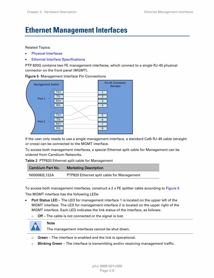
PTP 820G contains two FE management interfaces, which connect to a single RJ-45 physical
connector on the front panel (MGMT).
Figure 5 Management Interface Pin Connections
Management Switch
TX+
TX-
RX+
RX-
TX+
TX-
RX+
RX-
Port 1
Port 2
1
2
3
4
5
6
7
8
RJ-45 Connector
(female)
If the user only needs to use a single management interface, a standard Cat5 RJ-45 cable (straight
or cross) can be connected to the MGMT interface.
To access both management interfaces, a special Ethernet split cable for Management can be
ordered from Cambium Networks.
Table 2 PTP820 Ethernet split cable for Management
Cambium Part No. Marketing Description
N000082L122A PTP820 Ethernet split cable for Management
To access both management interfaces, construct a 2 x FE splitter cable according to Figure 5
The MGMT interface has the following LEDs:
Port Status LED – The LED for management interface 1 is located on the upper left of the
MGMT interface. The LED for management interface 2 is located on the upper right of the
MGMT interface. Each LED indicates the link status of the interface, as follows:
o Off – The cable is not connected or the signal is lost.
Note
The management interfaces cannot be shut down.
o Green – The interface is enabled and the link is operational.
o Blinking Green – The interface is transmitting and/or receiving management traffic.

Chapter 2: Hardware Description Ethernet Management Interfaces
phn-3968 001v000
Page 2-7
Figure 6 Management FE Interface LEDs

Chapter 2: Hardware Description DS1/E1 Interface (Optional)
phn-3968 001v000
Page 2-8
DS1/E1 Interface (Optional)
Related Topics:
TDM Services
DS1/E1 Interface Specifications
Optionally, PTP 820G can be ordered with an MDR69 connector in which 16 DS1 / E1 interfaces are
available (ports 1 through 16).
The DS1/E1 interface has the following LEDs
ACT LED – Indicates whether the TDM card is working properly (Green) or if there is an error or
a problem with the card’s functionality (Red).
E1/DS1 LED – Indicates whether the interfaces are enabled with no alarms (Green), with alarms
(Red), or no interfaces enabled (Off).
Figure 7 TDM Interface LEDs

Chapter 2: Hardware Description Radio Interfaces
phn-3968 001v000
Page 2-9
Radio Interfaces
PTP 820G includes one or two radio interfaces, depending on the hardware assembly option that
was selected. Each radio interface uses a TNC connector type. Each radio interface is connected to
an RFU via coaxial cable. This connection is used for traffic between the RFU and the IDU. It is also
used to provide -48V DC power from the IDU to the RFU, as well as for management and
configuration of the RFU.
The radio interfaces are labeled Radio 1 and, if there is a second radio interface, Radio 2.
Each radio interface has the following set of LEDs. The LEDs for Radio 1 are located to the right of
the interface. The LEDs for Radio 2 are located to the left of the interface.
The LEDs indicate the following:
ACT – Indicates whether the interface is working properly (Green) or if there is an error or a
problem with the interface’s functionality (Red), as follows:
o Off – The radio is disabled.
o Green – The radio is active and operating normally.
o Blinking Green – The radio is operating normally and is in standby mode.
o Red – There is a hardware failure.
o Blinking Red – Troubleshooting mode.
LINK – Indicates the status of the radio link, as follows:
o Green – The radio link is operational.
o Red – There is an LOF or Excessive BER alarm on the radio.
o Blinking Green – An IF loopback is activated, and the result is OK.
o Blinking Red – An IF loopback is activated, and the result is Failed.
RFU – Indicates the status of the RFU, as follows:
o Green – The RFU is functioning normally.
o Yellow – A minor RFU alarm or a warning is present, or the RFU is in TX mute mode, or, in
a protected configuration, the RFU is in standby mode.
o Red – A cable is disconnected, or a major or critical RFU alarm is present.
o Blinking Green – An RF loopback has been activated, and the result is OK.
o Blinking Red – An RF loopback has been activated, and the result is Failed.

Chapter 2: Hardware Description Radio Interfaces
phn-3968 001v000
Page 2-10
Figure 8 Radio Interface LEDs

Chapter 2: Hardware Description Power Interfaces
phn-3968 001v000
Page 2-11
Power Interfaces
PTP 820G receives an external supply of -48V current via one or two power interfaces (the second
power interface is optional for power redundancy). The PTP 820G monitors the power supply for
under-voltage and includes reverse polarity protection, so that if the positive (+) and negative (-)
inputs are mixed up, the system remains shut down.
The allowed power input range for the PTP 820G is -40V to -60V. An under voltage alarm is
triggered if the power goes below the allowed range, and an over voltage alarm is triggered if the
power goes above the allowed range.
There is an ACT LED for each power interface. The LED is Green when the voltage being fed to the
power interface is within range, and Red if the voltage is not within range or if a power cable is not
connected.
Figure 9 Power Interface LEDs

Chapter 2: Hardware Description Synchronization Interface
phn-3968 001v000
Page 2-12
Synchronization Interface
PTP 820G includes an RJ-45 synchronization interface for T3 clock input and T4 clock output. The
interface is labeled SYNC.
The synchronization interface contains two LEDs, one on the upper left of the interface and one on
the upper right of the interface, as follows:
T3 Status LED – Located on the upper left of the interface. Indicates the status of T3 input clock,
as follows:
o Off – There is no T3 input clock, or the input is illegal.
o Green – There is legal T3 input clock.
T4 Status LED – Located on the upper right of the interface. Indicates the status of T4 output
clock, as follows:
o Off – T4 output clock is not available.
o Green – T4 output clock is available.
o Blinking Green – The clock unit is in a holdover state.
Figure 10 Sync Interface LEDs

Chapter 2: Hardware Description Terminal Interface
phn-3968 001v000
Page 2-13
Terminal Interface
PTP 820G includes an RJ-45 terminal interface (RS-232). A local craft terminal can be connected to
the terminal interface for local CLI management of the unit.

Chapter 2: Hardware Description Unit/ACT LED
phn-3968 001v000
Page 2-14
Unit/ACT LED
A general ACT LED for the unit is located on the lower left of the PTP 820G front panel. This LED is
labeled UNIT/ACT, and indicates the general status of the unit, as follows:
Off – Power is off.
Green – Power is on, and no alarms are present on the unit.
Yellow – Power is on, and there are minor alarms or warnings on the unit.
Red – Power is on, and there are major or critical alarms on the unit.
Figure 11 Unit/ACT LED

Chapter 2: Hardware Description External Alarms
phn-3968 001v000
Page 2-15
External Alarms
PTP 820G includes a DB9 dry contact external alarms interface. The external alarms interface
supports five input alarms and a single output alarm.
The input alarms are configurable according to:
1 Intermediate
2 Critical
3 Major
4 Minor
5 Warning
The output alarm is configured according to predefined categories.

phn-3968 001v000
Page 3-1
Chapter 3: RFU Overview
PTP Radio Frequency Units (RFUs) were designed with sturdiness, power, simplicity, and
compatibility in mind. These advanced systems provide high-power transmission for short and
long distances and can be assembled and installed quickly and easily.
PTP RFUs deliver high capacity over 3.5-56 MHz channels with configurable modulation schemes.
RFU-Cs provides a range of modulations from QPSK to 1024 QAM.
The RFUs support low to high capacities for traditional voice, mission critical, and emerging
Ethernet services, with any mix of interfaces, pure Ethernet, pure TDM, or hybrid Ethernet and
TDM interfaces.
High spectral efficiency can be ensured with XPIC, using the same bandwidth for double the
capacity, via a single carrier, with vertical and horizontal polarizations.
The IDU and RFU are connected by a coaxial cable RG-223 (100 m/300 ft), Belden 9914/RG-8 (300
m/1000 ft) or equivalent, with an N-type connector (male) on the RFU and a TNC connector on the
IDU.
The antenna connection can be:
Direct mount using the same antenna type.

Chapter 3: RFU Overview RFU-C
phn-3968 001v000
Page 3-2
RFU-C
PTP RFU-C is a fully software configurable, state-of-the-art RFU that supports a broad
range of interfaces and capacities from 100 Mbps up to 650 Mbps. RFU-C operates in the
frequency range of 6-38 GHz. RFU-C supports low to high capacities for traditional voice
and Ethernet services, as well as PDH/SDH/SONET or hybrid Ethernet and TDM
interfaces.
With RFU-C, traffic capacity throughput and spectral efficiency are optimized with the desired
channel bandwidth. For maximum user choice flexibility, channel bandwidths from 3.5-56 MHz can
be selected together with a range of modulations. RFU-Ce provides a range of modulations from
QPSK to 1024 QAM.1
When RFU-C operates in co-channel dual polarization (CCDP) mode using XPIC, two carrier signals
can be transmitted over a single channel, using vertical and horizontal polarization. This enables
double capacity in the same spectrum bandwidth.
Main Features of RFU-C
Frequency range – Operates in the frequency range 6-38 GHz
More power in a smaller package - Up to 26 dBm for extended distance, enhanced availability,
use of smaller antennas
Configurable Channel Bandwidth – 3.5 MHz – 56 MHz
Compact, lightweight form factor - Reduces installation and warehousing costs
Supported configurations:
o 1+0 – direct mount
Efficient and easy installation - Direct mount installation with different antenna types
For additional information:
Specifcations
1 For details about supported modulation capabilities beyond 256 QAM using a standard
RFU-C, contact your Cambium Networks representative.

phn-3968 001v000
Page 4-1
Chapter 4: Activation Keys
This chapter describes PTP 820G’s activation key model. PTP 820G offers a pay as-you-grow
concept in which future capacity growth and additional functionality can be enabled with
activation keys. Each unit contains a single activation key.
Activation keys are divided into two categories:
Per Carrier – The activation key is per carrier.
Per Device – The activation key is per device, regardless of the number of carriers supported by
the device.
A 1+1 HSB configuration requires the same set of per-carrier activation key for both the active and
the protected carriers.
This chapter includes:
Working with Activation Keys
Demo Mode License
Activation Key-Enabled Features

Chapter 4: Activation Keys Working with Activation Keys
phn-3968 001v000
Page 4-2
Working with Activation Keys
Cambium Networks provides a System for managing activation keys. This system enables
authorized users to generate activation keys, which are generated per IDU serial number.
In order to upgrade an activation key, the activation-key must be entered into the PTP 820G. The
system checks and implements the new activation key, enabling access to new capacities and/or
features.
In the event that the activation-key-enabled capacity and feature set is exceeded an Activation Key
Violation alarm occurs. After a 48-hour grace period, all other alarms are hidden until the capacity
and features in use are brought within the activation key’s capacity and feature set.

Chapter 4: Activation Keys Demo Mode License
phn-3968 001v000
Page 4-3
Demo Mode License
The system can be used in demo mode, which enables all features for 60 days. Demo mdoe
expires 60 days from the time it was activated, and the most recent valid activation key cipher goes
into effect. The 60-day period is only counted when the system is powered up. Ten days before the
demo mode expires, an alarm is raised indicating to the user that demo license is about to expire.

Chapter 4: Activation Keys Activation Key-Enabled Features
phn-3968 001v000
Page 4-4
Activation Key-Enabled Features
As your network expands and additional functionality is desired, activation keys can be purchased
for the features described in the following table.
Table 3 Activation Key Types
Cambium Part
Number
Type (Per
Carrier/Per
Device)
Description For Addition
Information
Refer to
Capacity
Activation Key
Levels on page
4-6
Per Carrier Enables you to increase your system’s radio
capacity in gradual steps by upgrading your
capacity activation key level. Without a
capacity activation key, each carrier has a
capacity of 10 Mbps. Activation-Key-Enabled
capacity is available from 50 Mbps to 500
Mbps. Each RMC can be activation-key-
enabled for a different capacity.
Capacity
Summary
ACM Per Carrier Enables the use of Adaptive Coding and
Modulation (ACM) scripts.
Adaptive
Coding
Modulation
(ACM)
Multi-carrier
ABC
Per Carrier Enables Multi-Carrier ABC Multi-Carrier
ABC
Header De-
Duplication
Per Carrier Enables the use of Header De-Duplication,
which can be configured to operate at L2
through L4.
Header De-
Duplication
XPIC Per Carrier Enables the use of Cross Polarization Interface
Canceller (XPIC). Each carrier in the XPIC pair
must be licensed.
Cross
Polarization
Interference
Canceller (XPIC)
GE Port
Enabling
Per Device Enables the use of an Ethernet traffic port in
GE mode (10/100/1000baseT or 1000baseX). A
license is required for each Ethernet traffic
port that is used on the device. License can be
installed multiple times with dynamic
allocation inside the unit to enable multiple
GE ports.
Note: All Ethernet traffic ports are enabled in
FE mode (10/100baseT) by default with
requiring any license.
Ethernet Traffic
Interfaces

Chapter 4: Activation Keys Activation Key-Enabled Features
phn-3968 001v000
Page 4-5
Cambium Part
Number
Type (Per
Carrier/Per
Device)
Description For Addition
Information
Refer to CET
Node Activation
Key Levels on
page 4-7
Per Device Enables Carrier Ethernet Transport (CET) and
a number of Ethernet services (EVCs),
depending on the type of CET Node license:
Edge CET Node – Up to 8 EVCs.
Aggregation Level 1 CET Node – Up to 64
EVCs.
A CET Node license also enables the
following:
Network resiliency (MSTP/RSTP) for all
services.
Full QoS for all services including basic queue
buffer management (fixed queues buffer size
limit, tail-drop only) and eight queues per
port, no H-QoS.
LAG Support
Ethernet
Service Model
Quality of
Service (QoS)
Link
Aggregation
Groups (LAG)
N000082L050A Per Device Enables the following protocols for improving
network resiliency:
G.8032
Native TDM services 1:1 path protection
Network
Resiliency
N000082L044A Per Device Enables H-QoS.2 This license is required to
add service-bundles with dedicated queues to
interfaces. Without this license, only the
default eight queues per port are supported.
Quality of
Service (QoS)
N000082L038A Per Device Enables configurable (non-default) queue
buffer size limit for Green and Yellow frames.
Also enables WRED. The default queue buffer
size limit is 1 Mbits for Green frames and 0.5
Mbits for Yellow frames.
Quality of
Service (QoS)
N000082L052A Per Device Enables the G.8262 synchronization unit. This
license is required in order to provide end-to-
end synchronization distribution on the
physical layer. This license is also required to
use Synchronous Ethernet (SyncE).
Synchronization
N000082L041A Per Device Enables Frame Cut-Through. Frame Cut-
Through
2 H-QoS support is planned for future release.

Chapter 4: Activation Keys Activation Key-Enabled Features
phn-3968 001v000
Page 4-6
Cambium Part
Number
Type (Per
Carrier/Per
Device)
Description For Addition
Information
N000082L053A Per Device Enables TDM pseudowire services on units
with TDM interfaces. Without this activation
key, only native TDM services are supported.
TDM
Pseudowire
N000082L051A Per Device Enables secure management protocols (SSH,
HTTPS, SFTP, SNMPv3, and RADIUS).3
Secure
Communication
Channels
N000082L039A Per Device Enables Connectivity Fault Management
(CFM) per 802.1ag and 802.3ah (CET mode
only).4
Connectivity
Fault
Management
(FM)
N000082L040A Per Device Enables performance monitoring pursuant to
Y.1731 (CET mode only).5
Table 4 Capacity Activation Key Levels
Cambium Part Number Description
N000082L82A PTP 820G Act.Key - Capacity 100M with ACM Enabled
N000082L83A PTP 820G Act.Key - Capacity 500M with ACM Enabled
N000082L84A PTP 820G Act.Key - Capacity 650M with ACM Enabled
N000082L85A PTP 820G Act.Key - Capacity upgrade from 100 to 650M,
per carrier
N000082L86A PTP 820G Act.Key - Capacity upgrade from 100 to 500M,
per carrier
3 Support for SSH, HTTPS, SFTP, SNMPv3, and RADIUS is planned for future release.
4 FM support is planned for future release.
5 PM support is planned for future release.

Chapter 4: Activation Keys Activation Key-Enabled Features
phn-3968 001v000
Page 4-7
Table 5 CET Node Activation Key Levels
Cambium Part
Number
Description
N000082L037A Enables CET with up to 8 services/EVCs.
N000082L030A Enables CET with up to 64 services/EVCs.
N000082L031A Enables CET with up to 1024 services/EVCs.
N000082L055A Upgrades from "Edge-CET-Node" to "Agg-Lvl-1-CET-Node".
N000082L054A Upgrades from "Edge-CET-Node" to "Agg-Lvl-2-CET-Node".
phn-3968 001v000
Page 5-1
Chapter 5: Feature Description
This chapter describes the main PTP 820G features. The feature descriptions are divided into the
categories listed below.
This chapter includes:
Innovative Techniques to Boost Capacity and Reduce Latency
Radio Features
Ethernet FeaturesATPC enables the transmitter to operate at less than maximum power for most
of the time. When fading conditions occur, transmit power is increased as needed until the
maximum is reached.
The ATPC mechanism has several potential advantages, including less transmitter power
consumption and longer amplifier component life, thereby reducing overall system cost.
ATPC is frequently used as a means to mitigate frequency interference issues with the
environment, thus allowing new radio links to be easily coordinated in frequency congested areas.

Chapter 5: Feature Description Activation Key-Enabled Features
phn-3968 001v000
Page 5-2
Multi-Carrier ABC
This feature requires:
PTP 820G hardware assembly with two radio interfaces.
Note
Multi-Carrier ABC support is planned for future release.
Multi-Carrier Adaptive Bandwidth Control (Multi-Carrier ABC) is an innovative technology that
creates logical bundles of multiple radio links optimized for wireless backhaul applications. Multi-
Carrier ABC enables separate radio carriers to be combined into a virtual transport pipe for a high
capacity Ethernet link and individual TDM links. Both the Ethernet link and the TDM links will be
available over radios with individual variable capacity, and handled by a prioritizing scheme.
In Multi-Carrier ABC mode, traffic is divided among the carriers optimally at the radio frame level
without requiring Ethernet link aggregation (LAG). Load balancing is performed without regard to
the number of MAC addresses or the number of traffic flows. During fading events which cause
ACM modulation changes, each carrier fluctuates independently with hitless switchovers between
modulations, increasing capacity over a given bandwidth and maximizing spectrum utilization. In
such conditions, the TDM links can be preserved by a sophisticated prioritizing scheme configured
by the user. The result is 100% utilization of radio resources in which traffic load is balanced based
on instantaneous radio capacity per carrier.
The following diagram illustrates the Multi-Carrier ABC traffic flow.
Figure 22 Multi-Carrier ABC Traffic Flow
Carrier 1
Carrier 2
Traffic Splitter
Carrier 1
Carrier 2
Traffic
CombinerEth Eth
Carrier 3
Carrier 4
Carrier 3
Carrier 4

Chapter 5: Feature Description Activation Key-Enabled Features
phn-3968 001v000
Page 5-3
Multi-Carrier Configurations
In ABC Multi-Carrier mode, PTP 820G supports the following configurations:
2+0 ABC
1+1 BBS Space Diversity
Multi-Carrier ABC Operation
Multi-Carrier ABC divides each radio carrier into blocks of data. The block size, i.e., the number of
data bytes inside a block, is configured based on the capacity of the carrier’s ACM profile. The
block size may vary from one block to the other, independently for each radio carrier.
On the receiving side of the link, all blocks are aligned, which means that all channels must wait
for the slowest arriving block. Alignment does not add any delay to the slowest carrier. The latency
of the aggregated data flow is determined by the slowest arriving carrier.
A low ACM profile means more latency compared to a higher ACM profile. When all channels run
the same radio script, the latency variation for the aggregated data stream is determined by the
latency variation of one radio channel. This latency variation is slightly more complicated to
predict if the various radio carriers run different radio scripts, since each radio script has a unique
delay distribution. Multi-Carrier ABC can tolerate a large difference in the degree of delay between
the slowest and the fastest arriving carriers.
Graceful Degradation of Service
Multi-Carrier ABC provides for protection and graceful degradation of service in the event of failure
of an RFU or the slave carrier. This ensures that if one link is lost, not all data is lost. Instead,
bandwidth is simply reduced until the link returns to service.
The system determines which radio carriers contribute to the aggregated link, based on the
received channel qualities. Other criteria, such as ACM profile and latency, can also be used.
Adding or removing a channel is hitless.
When all channels are up and running, Multi-Carrier ABC provides the maximum available
aggregated capacity. Even when one or more carriers are operating at limited capacity or are
totally down, the data path remains error free. In the event of degradation in a particular carrier,
the carrier is removed from the aggregated link before bit errors arise, so as not to disturb the
aggregated data flow.
Multi-Carrier ABC and ACM
Multi-Carrier ABC automatically adapts to capacity changes that result from changes in the current
ACM profile. When an ACM profile change takes place on a specific carrier, Multi-Carrier ABC
responds by changing the block size of that channel.

Chapter 5: Feature Description Activation Key-Enabled Features
phn-3968 001v000
Page 5-4
BBS Space Diversity
This feature requires:
PTP 82G hardware assembly with two radio interfaces.
Note
2048 QAM support is planned for future release.
In long distance wireless links with relatively low frequency, multipath phenomena are common.
Both direct and reflected signals are received, which can cause distortion of the signal resulting in
signal fade. The impact of this distortion can vary over time, space, and frequency. This fading
phenomenon depends mainly on the link geometry and is more severe at long distance links and
over flat surfaces or water. It is also affected by air turbulence and water vapor, and can vary
quickly during temperature changes due to rapid changes in the reflections phase.
Fading can be flat or dispersive. In flat fading, all frequency components of the signal experience
the same magnitude of fading. In dispersive, or frequency selective fading, different frequency
components of the signal experience decorrelated fading.
Figure 23 Direct and Reflected Signals
Space Diversity is a common way to negate the effects of fading caused by multipath phenomena.
Space Diversity is implemented by placing two separate antennas at a distance from one another
that makes it statistically likely that if one antenna suffers from fading caused by signal reflection,
the other antenna will continue to receive a viable signal.
BBS Space Diversity requires two antennas and RFUs. The antennas must be separated by
approximately 15 to 20 meters. The same data stream is received by both antennas, radios, and
modems at the receiving end of the link. The Multi-Carrier ABC mechanism constantly monitors
the signal quality of the main and diversity carrier, and selects the signal with the best quality.
Switching between the main and diversity carriers is hitless.

Chapter 5: Feature Description Activation Key-Enabled Features
phn-3968 001v000
Page 5-5
Figure 24 1+1 BBS Space Diversity Configuration – Receiving Side
Radio & RMCRX
RX
MUX
SD
ABCRX
Radio Utilization PMs
PTP 820G supports the following counters, as well as additional PMs based on these counters:
Radio Traffic Utilization – Measures the percentage of radio capacity utilization, and used to
generate the following PMs for every 15-minute interval:
o Peak Utilization (%)
o Average Utilization (%)
o Over-Threshold Utilization (seconds). The utilization threshold can be defined by the user
(0-100%).
Radio Traffic Throughput – Measures the total effective Layer 2 traffic sent through the radio
(Mbps), and used to generate the following PMs for every 15-minute interval:
o Peak Throughput
o Average Throughput
o Over-Threshold Utilization (seconds). The threshold is defined as 0.
Radio Traffic Capacity – Measures the total L1 bandwidth (payload plus overheads) sent
through the radio (Mbps), and used to generate the following PMs for every 15-minute interval:
o Peak Capacity
o Average Capacity
o Over-Threshold Utilization (seconds). The threshold is defined as 0.
Frame Error Rate – Measures the frame error rate (%), and used to generate Frame Error Rate
PMs for every 15-minute interval.
Ethernet Features
Synchronization
TDM Services

Chapter 5: Feature Description Innovative Techniques to Boost Capacity and Reduce
Latency
phn-3968 001v000
Page 5-6
Innovative Techniques to Boost Capacity and
Reduce Latency
PTP 820G utilizes Cambium Network’s innovative technology to provide a high-capacity low-
latency solution. PTP 820G’s Header De-Duplication option is one of the innovative techniques that
enables PTP 820G to boost capacity and provide operators with efficient spectrum utilization, with
no disruption of traffic and no addition of latency.
Note
Header De-Duplication is planned for future release.
PTP 820G also utilizes established Cambium Networks technology to provide low latency
representing a 50% latency reduction for Ethernet services compared to the industry benchmark
for wireless backhaul.
Another of Cambium Network’s innovative features is Frame Cut-Through, which provides unique
delay and delay-variation control for delay-sensitive services. Frame Cut-Through enables high-
priority frames to bypass lower priority frames even when the lower-priority frames have already
begun to be transmitted. Once the high-priority frames are transmitted, transmission of the lower-
priority frames is resumed with no capacity loss and no re-transmission required.
This section includes:
Capacity Summary
Header De-Duplication
Latency
Frame Cut-Through
Capacity Summary
Each carrier in a PTP 820G provides the following capacity:
Supported Channels Bandwidth–7/14/28/30/40/50/56 MHz
All licensed bands – L6, U6, 7, 8, 10, 11, 13, 15, 18, 23, 26, 28, 31, 38 GHz
High scalability – From 100 Mbps to 500 Mbps, using the same hardware, including the same
RFU, and up to 1 Gbps with Header De-Duplication.
Modulations - QPSK to 2048 QAM
For additional information:
Capacity Specifications

Chapter 5: Feature Description Innovative Techniques to Boost Capacity and Reduce
Latency
phn-3968 001v000
Page 5-7
Header De-Duplication
Note
Header De-Duplication is planned for future release.
PTP 820G offers the option of Header De-Duplication, enabling operators to significantly improve
Ethernet throughput over the radio link without affecting user traffic. Header De-Duplication can be
configured to operate on various layers of the protocol stack saving bandwidth by reducing
unnecessary header overhead. Header Duplication is also some times knan as head compression.
Note
Without Header De-Duplication, PTP 820G still removes the IFG and Preamble fields.
This mechanism operates automatically, even if Header De-Duplication is not selected
by the user.
Figure 12 Header De-Duplication
Header De-Duplication identifies traffic flows and replaces the header fields with a "flow ID". This is
done using a sophisticated algorithm that learns unique flows by looking for repeating frame
headers in the traffic stream over the radio link and compressing them. The principle underlying
this feature is that frame headers in today’s networks use a long protocol stack that contains a
significant amount of redundant information.
In Header De-Duplication can be customized for optimal benefit accordingly to network usage. The
user can determine the layer or layers on which Header De-Duplication operates, with the
following options available:
Layer2 – Header De-Duplication operates on the Ethernet level.
MPLS – Header De-Duplication operates on the Ethernet and MPLS levels.
Layer3 – Header De-Duplication operates on the Ethernet and IP levels.
Layer4 – Header De-Duplication operates on all supported layers up to Layer 4.

Chapter 5: Feature Description Innovative Techniques to Boost Capacity and Reduce
Latency
phn-3968 001v000
Page 5-8
Tunnel – Header De-Duplication operates on Layer 2, Layer 3, and on the Tunnel layer for
packets carrying GTP or GRE frames.
Tunnel-Layer3 – Header De-Duplication operates on Layer 2, Layer 3, and on the Tunnel and T-
3 layers for packets carrying GTP or GRE frames.
Tunnel-Layer4 – Header De-Duplication operates on Layer 2, Layer 3, and on the Tunnel, T-3,
and T-4 layers for packets carrying GTP or GRE frames.
Operators must balance the depth of De-Duplication against the number of flows in order to
ensure maximum efficiency. Up to 256 concurrent flows are supported.
The following graphic illustrates how Header De-Duplication can save up to 148 bytes per frame.
Figure 13 Header De-Duplication Potential Throughput Savings per Layer
IP-20G
End User
Layer 2 | Untagged/C/S Tag/Double Tag
Up to 22 bytes compressed
Layer 2.5 | MPLS: up to 7 Tunnels (Untagged/C-Tag)
Up to 28 bytes compressed
Layer 3 | IPv4/IPv6
18/40 bytes compressed
Layer 4 | TCP/UDP
4/6 bytes compressed
Tunneling Layer | GTP (LTE) / GRE
6 bytes compressed
End User Inner Layer 3 | IPv4/IPv6
18/40 bytes compressed
End User Inner Layer 4 | TCP/UDP
4/6 bytes compressed

Chapter 5: Feature Description Innovative Techniques to Boost Capacity and Reduce
Latency
phn-3968 001v000
Page 5-9
Depnding on the packet size and network topology, Header De-Duplication can be increase
capacity by up to:
50% (256 byte packets)
25% (512 byte packets)
8% (1518 byte packets)
Header De-Duplication Counters
In order to help operators optimize Header De-Duplication, PTP 820G provides counters when
Header De-Duplication is enabled. These counters include real-time information, such as the
number of currently active flows and the number of flows by specific flow type. This information
can be used by operators to monitor network usage and capacity, and optimize the Header De-
Duplication settings. By monitoring the effectiveness of the Header De-Duplication settings, the
operator can adjust these settings to ensure that the network achieves the highest possible
effective throughput.
Latency
PTP 820G provides best-in-class latency (RFC-2544) for all channels, making it the obvious choice
for LTE (Long-Term Evolution) networks. See Ethernet Latency Specifications on page 8-30.
PTP 820G’s ability to meet the stringent latency requirements for LTE systems provides the key to
expanded broadband wireless services:
Longer radio chains
Larger radio rings
Shorter recovery times
More capacity
Easing of Broadband Wireless Access (BWA) limitations
Frame Cut-Through
Related topics:
Ethernet Latency Specifications
Egress Scheduling
Frame Cut-Through is a unique and innovative feature that ensures low latency for delay-
sensitive services, such as CES, VoIP, and control protocols. With Frame Cut-Through,
high-priority frames are pushed ahead of lower priority frames, even if transmission of
the lower priority frames has already begun. Once the high priority frame has been
transmitted, transmission of the lower priority frame is resumed with no capacity loss
and no re-transmission required. This provides operators with:
Immunity to head-of-line blocking effects – key for transporting high-priority, delay-sensitive
traffic.

Chapter 5: Feature Description Innovative Techniques to Boost Capacity and Reduce
Latency
phn-3968 001v000
Page 5-10
Reduced delay-variation and maximum-delay over the link:
o Reduced end-to-end delay for TDM services.
o Improved QoE for VoIP and other streaming applications.
o Expedited delivery of critical control frames.
Figure 14 Propagation Delay with and without Frame Cut-Through
Frame Cut-Through Basic Operation
Using Frame Cut-Through, frames assigned to high priority queues can pre-empt frames already in
transmission over the radio from other queues. Transmission of the preempted frames is resumed
after the cut-through with no capacity loss or re-transmission required. This feature provides
services that are sensitive to delay and delay variation, such as VoIP, with true transparency to
lower priority services, by enabling the transmission of a high-priority, low-delay traffic stream.
Figure 15 Frame Cut-Through
Frame 1 Frame 2 Frame 3Frame 4
StartFrame Cut-Through
Frame 4End
Frame 5
When enabled, Frame Cut-Through applies to all high priority frames, i.e., all frames that are
classified to a CoS queue with 4th (highest) priority.
Propagation Delay
Max Delay Max Delay
With Frame Cut-Through
Without Frame Cut- Through
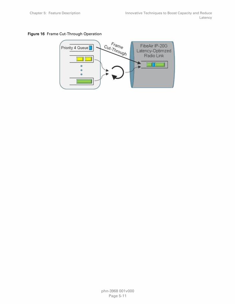
Chapter 5: Feature Description Innovative Techniques to Boost Capacity and Reduce
Latency
phn-3968 001v000
Page 5-11
Figure 16 Frame Cut-Through Operation

Chapter 5: Feature Description Radio Features
phn-3968 001v000
Page 5-12
Radio Features
This chapter describes the main PTP 820G radio features.
Cambium Networks was the first to introduce hitless and errorless Adaptive Coding Modulation
(ACM) to provide dynamic adjustment of the radio’s modulation from QPSK to 256 QAM. ACM
shifts modulations instantaneously in response to changes in fading conditions. PTP 820G utilizes
advanced ACM technology, and extends it to the range of QPSK to 1024 QAM.
PTP 820G also supports Cross Polarization Interface Canceller (XPIC). XPIC enables operators to
double their capacity by utilizing dual-polarization radio over a single-frequency channel, thereby
transmitting two separate carrier waves over the same frequency, but with alternating polarities.
This section includes:
Adaptive Coding Modulation (ACM)
Cross Polarization Interference Canceller (XPIC)
1+1 HSB Radio Protection
ATPC
Multi-Carrier ABC
BBS Space Diversity
Error! Reference source not found.
Adaptive Coding Modulation (ACM)
This feature requires:
ACM script
Related topics:
Cross Polarization Interference Canceller (XPIC)
Quality of Service (QoS)
PTP 820G employs full-range dynamic ACM. PTP 820G’s ACM mechanism copes with 90 dB per
second fading in order to ensure high transmission quality. PTP 820G’s ACM mechanism is
designed to work with PTP 820G’s QoS mechanism to ensure that high priority voice and data
frames are never dropped, thus maintaining even the most stringent service level agreements
(SLAs).
The hitless and errorless functionality of PTP 820G’s ACM has another major advantage in that it
ensures that TCP/IP sessions do not time-out. Without ACM, even interruptions as short as 50
milliseconds can lead to timeout of TCP/IP sessions, which are followed by a drastic throughout
decrease while these sessions recover.
Ten Working Points
PTP 820G implements ACM with 10 available working points, as follows:

Chapter 5: Feature Description Radio Features
phn-3968 001v000
Page 5-13
Table 6 ACM Working Points (Profiles)
Working Point (Profile) Modulation
Profile 0 QPSK
Profile 1 8 PSK
Profile 2 16 QAM
Profile 3 32 QAM
Profile 4 64 QAM
Profile 5 128 QAM
Profile 6 256 QAM
Profile 7 512 QAM
Profile 8 1024 QAM (Strong FEC)
Profile 9 1024 QAM (Light FEC)
Figure 17 Adaptive Coding and Modulation with 10 Working Points
Hitless and Errorless Step-by Step Adjustments
ACM works as follows. Assuming a system configured for 128 QAM with ~170 Mbps capacity over
a 30 MHz channel, when the receive signal Bit Error Ratio (BER) level reaches a predetermined
threshold, the system preemptively switches to 64 QAM and the throughput is stepped down to
~140 Mbps. This is an errorless, virtually instantaneous switch. The system continues to operate at
64 QAM until the fading condition either intensifies or disappears. If the fade intensifies, another
switch takes the system down to 32 QAM. If, on the other hand, the weather condition improves,
the modulation is switched back to the next higher step (e.g., 128 QAM) and so on, step by step
.The switching continues automatically and as quickly as needed, and can reach all the way down
to QPSK during extreme conditions.

Chapter 5: Feature Description Radio Features
phn-3968 001v000
Page 5-14
ACM Radio Scripts
An ACM radio script is constructed of a set of profiles. Each profile is defined by a modulation
order (QAM) and coding rate, and defines the profile’s capacity (bps). When an ACM script is
activated, the system automatically chooses which profile to use according to the channel fading
conditions.
The ACM TX profile can be different from the ACM RX profile.
The ACM TX profile is determined by remote RX MSE performance. The RX end is the one that
initiates an ACM profile upgrade or downgrade. When MSE improves above a predefined
threshold, RX generates a request to the remote TX to upgrade its profile. If MSE degrades below
a predefined threshold, RX generates a request to the remote TX to downgrade its profile.
ACM profiles are decreased or increased in an errorless operation, without affecting traffic.
For ACM to be active, the ACM script must be run in Adaptive mode. In this mode, the ACM engine
is running, which means that the radio adapts its profile according to the channel fading
conditions. Adaptive mode requires an ACM activation key.
Users also have the option of running an ACM script in Fixed mode. In this mode, ACM is not
active. Instead, the user can select the specific profile from all available profiles in the script. The
selected profile is the only profile that will be valid, and the ACM engine will be forced to be OFF.
Fixed mode can be chosen without an ACM activation key.
In the case of XPIC/ACM scripts, all the required conditions for XPIC apply.
The user can define a maximum profile. For example, if the user selects a maximum profile of 5,
the system will not climb above profile 5, even if channel fading conditions allow it.
ACM Benefits
The advantages of PTP 820G’s dynamic ACM include:
Maximized spectrum usage
Increased capacity over a given bandwidth
10 working points, with~3 db system gain for each point change
Hitless and errorless modulation/coding changes, based on signal quality
Adaptive Radio Tx Power per modulation for maximum system gain per working point
An integrated QoS mechanism that enables intelligent congestion management to ensure that
high priority traffic is not affected during link fading conditions.
ACM and Built-In QoS
PTP 820G’s ACM mechanism is designed to work with PTP 820G’s QoS mechanism to ensure that
high priority voice and data frames are never dropped, thus maintaining even the most stringent
SLAs. Since QoS provides priority support for different classes of service, according to a wide
range of criteria, users can configure PTP 820G to discard only low priority frames as conditions
deteriorate.
If you want to rely on an external switch’s QoS, ACM can work with the switch via the flow control
mechanism supported in the radio.

Chapter 5: Feature Description Radio Features
phn-3968 001v000
Page 5-15
ACM and 1+1 HSB
When ACM is activated together with 1+1 HSB protection, it is essential to feed the active RFU via
the main channel of the coupler (lossless channel), and to feed the standby RFU via the secondary
channel of the coupler (-6db attenuated channel). This maximizes system gain and optimizes ACM
behavior for the following reasons:
In the TX direction, the power will experience minimal attenuation.
In the RX direction, the received signal will be minimally attenuated. Thus, the receiver will be
able to lock on a higher ACM profile (according to what is dictated by the RF channel
conditions).
The following ACM behavior should be expected in a 1+1 configuration:
In the TX direction, the Active TX will follow the remote Active RX ACM requests (according to
the remote Active Rx MSE performance).
The Standby TX might have the same profile as the Active TX, or might stay at the lowest
profile (profile-0). That depends on whether the Standby TX was able to follow the remote RX
Active unit’s ACM requests (only the active remote RX sends ACM request messages).
In the RX direction, both the active and the standby carriers follow the remote Active TX profile
(which is the only active transmitter).
Cross Polarization Interference Canceller (XPIC)
This feature requires:
PTP 820G hardware assembly with two radio interfaces.
XPIC script
XPIC is one of the best ways to break the barriers of spectral efficiency. Using dual-polarization
radio over a single-frequency channel, a dual polarization radio transmits two separate carrier
waves over the same frequency, but using alternating polarities. Despite the obvious advantages
of dual-polarization, one must also keep in mind that typical antennas cannot completely isolate
the two polarizations. In addition, propagation effects such as rain can cause polarization rotation,
making cross-polarization interference unavoidable.

Chapter 5: Feature Description Radio Features
phn-3968 001v000
Page 5-16
Figure 18 Dual Polarization
The relative level of interference is referred to as cross-polarization discrimination (XPD). While
lower spectral efficiency systems (with low SNR requirements such as QPSK) can easily tolerate
such interference, higher modulation schemes cannot and require XPIC. PTP 820G’s XPIC
algorithm enables detection of both streams even under the worst levels of XPD such as 10 dB.
PTP 820G accomplishes this by adaptively subtracting from each carrier the interfering cross
carrier, at the right phase and level. For high-modulation schemes such as 1024 QAM, operating at
a frequency of 30 GHz, an improvement factor of more than 20 dB is required so that cross-
interference does not adversely affect performance.
XPIC Implementation
PTP 820G units with dual radio interfaces can support XPIC in a single unit utilizing the two
carriers.
The XPIC mechanism utilizes the received signals from the V and H modems to extract the V and H
signals and cancel the cross polarization interference due to physical signal leakage between V and
H polarizations.
The following figure is a basic graphic representation of the signals involved in this process.
Figure 19 XPIC Implementation
The H+v signal is the combination of the desired signal H (horizontal) and the interfering signal V
(in lower case, to denote that it is the interfering signal). The same happens with the vertical (V)
signal reception= V+h. The XPIC mechanism uses the received signals from both feeds and,
manipulates them to produce the desired data.

Chapter 5: Feature Description Radio Features
phn-3968 001v000
Page 5-17
Figure 20 XPIC – Impact of Misalignments and Channel Degradation
PTP 820G’s XPIC reaches a BER of 10e-6 at a high level of co-channel interference (modulation-
dependent). For exact figures, contact your Cambium representative.
Conditions for XPIC
XPIC is enabled by selecting an XPIC script for each carrier. In order for XPIC to be operational, all
the following conditions must be met:
Communications with the RFU must be established by both radio interfaces.
RFU type must be the same for both carriers.
The frequency of both radios must be equal.
1+1 HSB protection must not be enabled.
The same script must be loaded for both carriers.
The script must support XPIC
If any of these conditions is not met, an alarm will alert the user. In addition, events will inform the
user which conditions are not met.
1+1 HSB Radio Protection
This feature requires:
PTP 820G hardware assembly with two radio interfaces.
PTP 820G offers radio redundancy via 1+1 HSB protection. 1+1 HSB protection provides full
protection in the event of interface, signal, or RFU failure.
The interfaces in a protected pair operate in active and standby mode. If there is a failure in the
active radio interface or RFU, the standby interface and RFU pair switches to active mode.
Each carrier in a protected pair reports its status to the CPU. The CPU is responsible for
determining when a switchover takes place.
In a 1+1 HSB configuration, the RFUs must be the same type and must have the same
configuration.

Chapter 5: Feature Description Radio Features
phn-3968 001v000
Page 5-18
PTP 820G includes a mismatch mechanism that detects if there is a mismatch between the radio
configurations of the local and mate interfaces and RFUs. This mechanism is activated by the
system periodically and independently of other protection mechanisms, at fixed intervals. It is
activated asynchronously for both the active and the standby carriers. Once the mismatch
mechanism detects a configuration mismatch, it raises a Mate Configuration Mismatch alarm.
When the configuration of the active and standby carriers is changed to be identical, the
mechanism clears the Mate Configuration Mismatch alarm.
In order to align the configuration between the active and standby carriers, the user must first
complete the required configuration of the active radio interface, and then perform a copy to mate
command. This command copies the entire configuration of the active interface to the standby
interface to achieve full configuration alignment between the active and standby carriers.
When a pair of carriers is defined as a 1+1 HSB pair, any configuration performed on the active
carrier will be automatically copied to the standby carrier, in order to maintain the carrier
configuration alignment. This makes it unnecessary to perform a copy-to-mate command when a
configuration change is made.
Revertive HSB Protection
In an HSB protection scheme, the active and standby radios are usually connected to the antenna
with a coupler. This causes a -6dB loss on the secondary path on each side of the link, resulting in
a 12dB increase in the total path loss for the link. This additional path loss will either reduce the
link’s fade margin or increase the power consumption of the Power Amplifier (PA) in order to
compensate for the additional path loss.
Figure 21 Path Loss on Secondary Path of 1+1 HSB Protection Link
-6dB
Coupler
-6dB
Primary Radio
Secondary Radio
Primary Radio
Secondary Radio
Coupler
Main Path
Coupling Path
Main Path
Coupling Path
PTP 820G supports revertive HSB protection. The advantage of using revertive HSB mode is that
the radio link budget will benefit from additional gain whenever it is possible to activate the
primary path.
In revertive HSB protection mode, user defines the primary radio on each side of the link. The
primary radio should be the radio on the coupler’s main path and the secondary radio should be
the radio on the coupling path.
The system monitors the availability of the primary path at all times. Whenever the primary path is
operational and available, without any alarms, but the secondary path is active, the system
initiates a revertive protection switch. Every revertive protection switch is recorded as an event in
the event log.

Chapter 5: Feature Description Radio Features
phn-3968 001v000
Page 5-19
Note
Each protection switch causes traffic disruption.
Switchover Triggers
The following events trigger switchover for 1+1 HSB protection according to their priority, with the
highest priority triggers listed first.
6 Hardware module missing
7 Lockout
8 Force switch
9 Traffic failures
10 Manual switch
ATPC
ATPC is a closed-loop mechanism by which each carrier changes the transmitted signal power
according to the indication received across the link, in order to achieve a desired RSL on the other
side of the link.
ATPC enables the transmitter to operate at less than maximum power for most of the time. When
fading conditions occur, transmit power is increased as needed until the maximum is reached.
The ATPC mechanism has several potential advantages, including less transmitter power
consumption and longer amplifier component life, thereby reducing overall system cost.
ATPC is frequently used as a means to mitigate frequency interference issues with the
environment, thus allowing new radio links to be easily coordinated in frequency congested areas.

Chapter 5: Feature Description Radio Features
phn-3968 001v000
Page 5-20
Multi-Carrier ABC
This feature requires:
PTP 820G hardware assembly with two radio interfaces.
Note
Multi-Carrier ABC support is planned for future release.
Multi-Carrier Adaptive Bandwidth Control (Multi-Carrier ABC) is an innovative technology that
creates logical bundles of multiple radio links optimized for wireless backhaul applications. Multi-
Carrier ABC enables separate radio carriers to be combined into a virtual transport pipe for a high
capacity Ethernet link and individual TDM links. Both the Ethernet link and the TDM links will be
available over radios with individual variable capacity, and handled by a prioritizing scheme.
In Multi-Carrier ABC mode, traffic is divided among the carriers optimally at the radio frame level
without requiring Ethernet link aggregation (LAG). Load balancing is performed without regard to
the number of MAC addresses or the number of traffic flows. During fading events which cause
ACM modulation changes, each carrier fluctuates independently with hitless switchovers between
modulations, increasing capacity over a given bandwidth and maximizing spectrum utilization. In
such conditions, the TDM links can be preserved by a sophisticated prioritizing scheme configured
by the user. The result is 100% utilization of radio resources in which traffic load is balanced based
on instantaneous radio capacity per carrier.
The following diagram illustrates the Multi-Carrier ABC traffic flow.
Figure 22 Multi-Carrier ABC Traffic Flow
Carrier 1
Carrier 2
Traffic Splitter
Carrier 1
Carrier 2
Traffic
CombinerEth Eth
Carrier 3
Carrier 4
Carrier 3
Carrier 4

Chapter 5: Feature Description Radio Features
phn-3968 001v000
Page 5-21
Multi-Carrier Configurations
In ABC Multi-Carrier mode, PTP 820G supports the following configurations:
2+0 ABC
1+1 BBS Space Diversity
Multi-Carrier ABC Operation
Multi-Carrier ABC divides each radio carrier into blocks of data. The block size, i.e., the number of
data bytes inside a block, is configured based on the capacity of the carrier’s ACM profile. The
block size may vary from one block to the other, independently for each radio carrier.
On the receiving side of the link, all blocks are aligned, which means that all channels must wait
for the slowest arriving block. Alignment does not add any delay to the slowest carrier. The latency
of the aggregated data flow is determined by the slowest arriving carrier.
A low ACM profile means more latency compared to a higher ACM profile. When all channels run
the same radio script, the latency variation for the aggregated data stream is determined by the
latency variation of one radio channel. This latency variation is slightly more complicated to
predict if the various radio carriers run different radio scripts, since each radio script has a unique
delay distribution. Multi-Carrier ABC can tolerate a large difference in the degree of delay between
the slowest and the fastest arriving carriers.
Graceful Degradation of Service
Multi-Carrier ABC provides for protection and graceful degradation of service in the event of failure
of an RFU or the slave carrier. This ensures that if one link is lost, not all data is lost. Instead,
bandwidth is simply reduced until the link returns to service.
The system determines which radio carriers contribute to the aggregated link, based on the
received channel qualities. Other criteria, such as ACM profile and latency, can also be used.
Adding or removing a channel is hitless.
When all channels are up and running, Multi-Carrier ABC provides the maximum available
aggregated capacity. Even when one or more carriers are operating at limited capacity or are
totally down, the data path remains error free. In the event of degradation in a particular carrier,
the carrier is removed from the aggregated link before bit errors arise, so as not to disturb the
aggregated data flow.
Multi-Carrier ABC and ACM
Multi-Carrier ABC automatically adapts to capacity changes that result from changes in the current
ACM profile. When an ACM profile change takes place on a specific carrier, Multi-Carrier ABC
responds by changing the block size of that channel.

Chapter 5: Feature Description Radio Features
phn-3968 001v000
Page 5-22
BBS Space Diversity
This feature requires:
PTP 82G hardware assembly with two radio interfaces.
Note
2048 QAM support is planned for future release.
In long distance wireless links with relatively low frequency, multipath phenomena are common.
Both direct and reflected signals are received, which can cause distortion of the signal resulting in
signal fade. The impact of this distortion can vary over time, space, and frequency. This fading
phenomenon depends mainly on the link geometry and is more severe at long distance links and
over flat surfaces or water. It is also affected by air turbulence and water vapor, and can vary
quickly during temperature changes due to rapid changes in the reflections phase.
Fading can be flat or dispersive. In flat fading, all frequency components of the signal experience
the same magnitude of fading. In dispersive, or frequency selective fading, different frequency
components of the signal experience decorrelated fading.
Figure 23 Direct and Reflected Signals
Space Diversity is a common way to negate the effects of fading caused by multipath phenomena.
Space Diversity is implemented by placing two separate antennas at a distance from one another
that makes it statistically likely that if one antenna suffers from fading caused by signal reflection,
the other antenna will continue to receive a viable signal.
BBS Space Diversity requires two antennas and RFUs. The antennas must be separated by
approximately 15 to 20 meters. The same data stream is received by both antennas, radios, and
modems at the receiving end of the link. The Multi-Carrier ABC mechanism constantly monitors
the signal quality of the main and diversity carrier, and selects the signal with the best quality.
Switching between the main and diversity carriers is hitless.

Chapter 5: Feature Description Radio Features
phn-3968 001v000
Page 5-23
Figure 24 1+1 BBS Space Diversity Configuration – Receiving Side
Radio & RMCRX
RX
MUX
SD
ABCRX
Radio Utilization PMs
PTP 820G supports the following counters, as well as additional PMs based on these counters:
Radio Traffic Utilization – Measures the percentage of radio capacity utilization, and used to
generate the following PMs for every 15-minute interval:
o Peak Utilization (%)
o Average Utilization (%)
o Over-Threshold Utilization (seconds). The utilization threshold can be defined by the user
(0-100%).
Radio Traffic Throughput – Measures the total effective Layer 2 traffic sent through the radio
(Mbps), and used to generate the following PMs for every 15-minute interval:
o Peak Throughput
o Average Throughput
o Over-Threshold Utilization (seconds). The threshold is defined as 0.
Radio Traffic Capacity – Measures the total L1 bandwidth (payload plus overheads) sent
through the radio (Mbps), and used to generate the following PMs for every 15-minute interval:
o Peak Capacity
o Average Capacity
o Over-Threshold Utilization (seconds). The threshold is defined as 0.
Frame Error Rate – Measures the frame error rate (%), and used to generate Frame Error Rate
PMs for every 15-minute interval.

Chapter 5: Feature Description Ethernet Features
phn-3968 001v000
Page 5-24
Ethernet Features
PTP 820G features a service-oriented Ethernet switching fabric. PTP 820G contains four electrical
and two optical 1 GE Ethernet interfaces, for a total of six Ethernet interfaces available for traffic.
PTP 820G also includes two FE interfaces for management.
PTP 820G’s service-oriented Ethernet paradigm enables operators to configure VLAN definition
and translation, CoS, security, and network resiliency on a service, service-point, and interface
level.
PTP 820G provides personalized and granular QoS that enables operators to customize traffic
management parameters per customer, application, service type, or in any other way that reflects
the operator’s business and network requirements.
This section includes:
Ethernet Services Overview
PTP 820G’s Ethernet Capabilities
Supported Standards
Ethernet Service Model
Ethernet Interfaces
Quality of Service (QoS)
Global Switch Configuration
Network Resiliency
OAM
Ethernet Services Overview
The PTP 820G services model is premised on supporting the standard MEF services (MEF 6, 10),
and builds upon this support by the use of very high granularity and flexibility. Operationally, the
PTP 820G Ethernet services model is designed to offer a rich feature set combined with simple and
user-friendly configuration, enabling users to plan, activate, and maintain any packet-based
network scenario.
This section first describes the basic Ethernet services model as it is defined by the MEF, then goes
on to provide a basic overview of PTP 820G‘s Ethernet services implementation.
The following figure illustrates the basic MEF Ethernet services model.
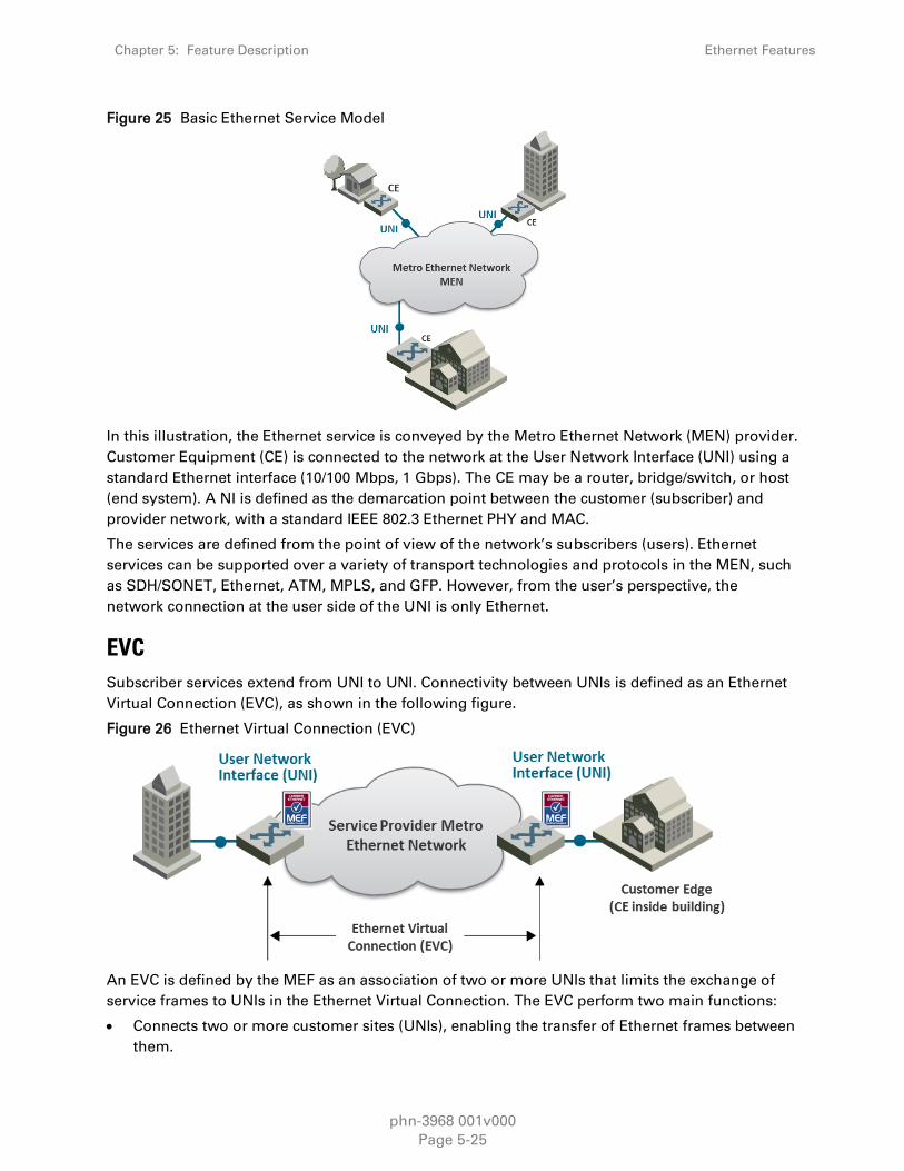
Chapter 5: Feature Description Ethernet Features
phn-3968 001v000
Page 5-25
Figure 25 Basic Ethernet Service Model
In this illustration, the Ethernet service is conveyed by the Metro Ethernet Network (MEN) provider.
Customer Equipment (CE) is connected to the network at the User Network Interface (UNI) using a
standard Ethernet interface (10/100 Mbps, 1 Gbps). The CE may be a router, bridge/switch, or host
(end system). A NI is defined as the demarcation point between the customer (subscriber) and
provider network, with a standard IEEE 802.3 Ethernet PHY and MAC.
The services are defined from the point of view of the network’s subscribers (users). Ethernet
services can be supported over a variety of transport technologies and protocols in the MEN, such
as SDH/SONET, Ethernet, ATM, MPLS, and GFP. However, from the user’s perspective, the
network connection at the user side of the UNI is only Ethernet.
EVC
Subscriber services extend from UNI to UNI. Connectivity between UNIs is defined as an Ethernet
Virtual Connection (EVC), as shown in the following figure.
Figure 26 Ethernet Virtual Connection (EVC)
An EVC is defined by the MEF as an association of two or more UNIs that limits the exchange of
service frames to UNIs in the Ethernet Virtual Connection. The EVC perform two main functions:
Connects two or more customer sites (UNIs), enabling the transfer of Ethernet frames between
them.

Chapter 5: Feature Description Ethernet Features
phn-3968 001v000
Page 5-26
Prevents data transfer involving customer sites that are not part of the same EVC. This feature
enables the EVC to maintain a secure and private data channel.
A single UNI can support multiple EVCs via the Service Multiplexing attribute. An ingress service
frame that is mapped to the EVC can be delivered to one or more of the UNIs in the EVC, other
than the ingress UNI. It is vital to avoid delivery back to the ingress UNI, and to avoid delivery to a
UNI that does not belong to the EVC. An EVC is always bi-directional in the sense that ingress
service frames can originate at any UNI in an EVC.
Service frames must be delivered with the same Ethernet MAC address and frame structure that
they had upon ingress to the service. In other words, the frame must be unchanged from source to
destination, in contrast to routing in which headers are discarded. Based on these characteristics,
an EVC can be used to form a Layer 2 private line or Virtual Private Network (VPN).
One or more VLANs can be mapped (bundled) to a single EVC.
The MEF has defined three types of EVCs:
1 Point to Point EVC – Each EVC contains exactly two UNIs. The following figure shows two
point-to-point EVCs connecting one site to two other sites.
Figure 27 Point to Point EVC
2 Multipoint (Multipoint-to-Multipoint) EVC – Each EVC contains two or more UNIs. In the
figure below, three sites belong to a single Multipoint EVC and can forward Ethernet frames to
each other.
Figure 28 Multipoint to Multipoint EVC
3 Rooted Multipoint EVC (Point-to-Multipoint) – Each EVC contains one or more UNIs, with
one or more UNIs defined as Roots, and the others defined as Leaves. The Roots can forward
frames to the Leaves. Leaves can only forward frames to the Roots, but not to other Leaves.

Chapter 5: Feature Description Ethernet Features
phn-3968 001v000
Page 5-27
Figure 29 Rooted Multipoint EVC
In the PTP 820G, an EVC is defined by either a VLAN or by Layer 1 connectivity (Pipe Mode).
Bandwidth Profile
The bandwidth profile (BW profile) is a set of traffic parameters that define the maximum limits of
the customer’s traffic.
At ingress, the bandwidth profile limits the traffic transmitted into the network:
Each service frame is checked against the profile for compliance with the profile.
Bandwidth profiles can be defined separately for each UNI (MEF 10.2).
Service frames that comply with the bandwidth profile are forwarded.
Service frames that do not comply with the bandwidth profile are dropped at the ingress
interface.
The MEF has defined the following three bandwidth profile service attributes:
Ingress BW profile per ingress UNI
Ingress BW profile per EVC
Ingress BW profile per CoS identifier
The BW profile service attribute consists of four traffic parameters:
CIR (Committed Information Rate)
CBS (Committed Burst Size)
EIR (Excess Information Rate)
EBS (Excess Burst Size)
Bandwidth profiles can be applied per UNI, per EVC at the UNI, or per CoS identifier for a specified
EVC at the UNI.
The Color of the service frame is used to determine its bandwidth profile. If the service frame
complies with the CIR and EIR defined in the bandwidth profile, it is marked Green. In this case, the
average and maximum service frame rates are less than or equal to the CIR and CBS, respectively.

Chapter 5: Feature Description Ethernet Features
phn-3968 001v000
Page 5-28
If the service frame does not comply with the CIR defined in the bandwidth profile, but does
comply with the EIR and EBS, it is marked Yellow. In this case, the average service frame rate is
greater than the CIR but less than the EIR, and the maximum service frame size is less than the
EBS.
If the service frame fails to comply with both the CIR and the EIR defined in the bandwidth profile,
it is marked Red and discarded.
In the PTP 820G, bandwidth profiles are constructed using a full standardized TrTCM policer
mechanism.
Ethernet Services Definitions
The MEF provides a model for defining Ethernet services. The purpose of the MEF model is to help
subscribers better understand the variations among different types of Ethernet services. PTP 820G
supports a variety of service types defined by the MEF. All of these service types share some
common attributes, but there are also differences as explained below.
Ethernet service types are generic constructs used to create a broad range of services. Each
Ethernet service type has a set of Ethernet service attributes that define the characteristics of the
service. These Ethernet service attributes in turn are associated with a set of parameters that
provide various options for the various service attributes.
Figure 30 MEF Ethernet Services Definition Framework
The MEF defines three generic Ethernet service type constructs, including their associated service
attributes and parameters:
Ethernet Line (E-Line)
Ethernet LAN (E-LAN)
Ethernet Tree (E-Tree)
Multiple Ethernet services are defined for each of the three generic Ethernet service types. These
services are differentiated by the method for service identification used at the UNIs. Services using
All-to-One Bundling UNIs (port-based) are referred to as “Private” services, while services using
Service Multiplexed (VLAN-based) UNIs are referred to as “Virtual Private” services. This
relationship is shown in the following table.

Chapter 5: Feature Description Ethernet Features
phn-3968 001v000
Page 5-29
Table 7 MEF-Defined Ethernet Service Types
Port Based
(All to One Bundling)
VLAN-BASED
(EVC identified by VLAN ID)
Ethernet Private Line (EPL) Ethernet Virtual Private Line (EVPL)
Ethernet Private LAN (EP-LAN) Ethernet Virtual Private LAN (EVP-LAN)
Ethernet Private Tree (EP-Tree) Ethernet Virtual Private Tree (EVP-Tree)
All-to-One Bundling refers to a UNI attribute in which all Customer Edge VLAN IDs (CE-VLAN IDs)
entering the service via the UNI are associated with a single EVC. Bundling refers to a UNI attribute
in which more than one CE-VLAN ID can be associated with an EVC.
To fully specify an Ethernet service, additional service attributes must be defined in addition to the
UNI and EVC service attributes. These service attributes can be grouped under the following
categories:
Ethernet physical interfaces
Traffic parameters
Performance parameters
Class of service
Service frame delivery
VLAN tag support
Service multiplexing
Bundling
Security filters
E-Line Service
The Ethernet line service (E-Line service) provides a point-to-point Ethernet Virtual Connection
(EVC) between two UNIs. The E-Line service type can be used to create a broad range of Ethernet
point-to-point services and to maintain the necessary connectivity. In its simplest form, an E-Line
service type can provide symmetrical bandwidth for data sent in either direction with no
performance assurances, e.g., best effort service between two FE UNIs. In more sophisticated
forms, an E-Line service type can provide connectivity between two UNIs with different line rates
and can be defined with performance assurances such as CIR with an associated CBS, EIR with an
associated EBS, delay, delay variation, loss, and availability for a given Class of Service (CoS)
instance. Service multiplexing can occur at one or both UNIs in the EVC. For example, more than
one point-to-point EVC can be offered on the same physical port at one or both of the UNIs.

Chapter 5: Feature Description Ethernet Features
phn-3968 001v000
Page 5-30
Figure 31 E-Line Service Type Using Point-to-Point EVC
Ethernet Private Line Service
An Ethernet Private Line (EPL) service is specified using an E-Line Service type. An EPL service
uses a point-to-point EVC between two UNIs and provides a high degree of transparency for
service frames between the UNIs that it interconnects such that the service frame’s header and
payload are identical at both the source and destination UNI when the service frame is delivered
(L1 service). A dedicated UNI (physical interface) is used for the service and service multiplexing is
not allowed. All service frames are mapped to a single EVC at the UNI. In cases where the EVC
speed is less than the UNI speed, the CE is expected to shape traffic to the ingress bandwidth
profile of the service to prevent the traffic from being discarded by the service. The EPL is a port-
based service, with a single EVC across dedicated UNIs providing site-to-site connectivity. EPL is
the most popular Ethernet service type due to its simplicity, and is used in diverse applications
such as replacing a TDM private line.
Figure 32 EPL Application Example
Ethernet Virtual Private Line Service
An Ethernet Virtual Private Line (EVPL) is created using an E-Line service type. An EVPL can be
used to create services similar to EPL services. However, several characteristics differ between EPL
and EVPL services.
First, an EVPL provides for service multiplexing at the UNI, which means it enables multiple EVCs
to be delivered to customer premises over a single physical connection (UNI). In contrast, an EPL
only enables a single service to be delivered over a single physical connection.
Second, the degree of transparency for service frames is lower in an EVPL than in an EPL.

Chapter 5: Feature Description Ethernet Features
phn-3968 001v000
Page 5-31
Since service multiplexing is permitted in EVPL services, some service frames may be sent to one
EVC while others may be sent to other EVCs. EVPL services can be used to replace Frame Relay
and ATM L2 VPN services, in order to deliver higher bandwidth, end-to-end services.
Figure 33 EVPL Application Example
E-LAN Service
The E-LAN service type is based on Multipoint to Multipoint EVCs, and provides multipoint
connectivity by connecting two or more UNIs. Each site (UNI) is connected to a multipoint EVC,
and customer frames sent from one UNI can be received at one or more UNIs. If additional sites
are added, they can be connected to the same multipoint EVC, simplifying the service activation
process. Logically, from the point of view of a customer using an E-LAN service, the MEN can be
viewed as a LAN.
Figure 34 E-LAN Service Type Using Multipoint-to-Multipoint EVC
The E-LAN service type can be used to create a broad range of services. In its basic form, an E-LAN
service can provide a best effort service with no performance assurances between the UNIs. In
more sophisticated forms, an E-LAN service type can be defined with performance assurances
such as CIR with an associated CBS, EIR with an associated EBS, delay, delay variation, loss, and
availability for a given CoS instance.
For an E-LAN service type, service multiplexing may occur at none, one, or more than one of the
UNIs in the EVC. For example, an E-LAN service type (Multipoint-to-Multipoint EVC) and an E-Line
service type (Point-to-Point EVC) can be service multiplexed at the same UNI. In such a case, the E-
LAN service type can be used to interconnect other customer sites while the E-Line service type is
used to connect to the Internet, with both services offered via service multiplexing at the same
UNI.

Chapter 5: Feature Description Ethernet Features
phn-3968 001v000
Page 5-32
E-LAN services can simplify the interconnection among a large number of sites, in comparison to
hub/mesh topologies implemented using point-to-point networking technologies such as Frame
Relay and ATM.
For example, consider a point-to-point network configuration implemented using E-Line services. If
a new site (UNI) is added, it is necessary to add a new, separate EVC to all of the other sites in
order to enable the new UNI to communicate with the other UNIs, as shown in the following
figure.
Figure 35 Adding a Site Using an E-Line service
In contrast, when using an E-LAN service, it is only necessary to add the new UNI to the multipoint
EVC. No additional EVCs are required, since the E-LAN service uses a multipoint to multipoint EVC
that enables the new UNI to communicate with each of the others UNIs. Only one EVC is required
to achieve multi-site connectivity, as shown in the following figure.
Figure 36 Adding a Site Using an E-LAN service
The E-LAN service type can be used to create a broad range of services, such as private LAN and
virtual private LAN services.
Ethernet Private LAN Service
It is often desirable to interconnect multiple sites using a Local Area Network (LAN) protocol model
and have equivalent performance and access to resources such as servers and storage. Customers
commonly require a highly transparent service that connects multiple UNIs. The Ethernet Private
LAN (EP-LAN) service is defined with this in mind, using the E-LAN service type. The EP-LAN is a
Layer 2 service in which each UNI is dedicated to the EP-LAN service. A typical use case for EP-
LAN services is Transparent LAN.

Chapter 5: Feature Description Ethernet Features
phn-3968 001v000
Page 5-33
The following figure shows an example of an EP-LAN service in which the service is defined to
provide Customer Edge VLAN (CE-VLAN) tag preservation and tunneling for key Layer 2 control
protocols. Customers can use this service to configure VLANs across the sites without the need to
coordinate with the service provider. Each interface is configured for All-to-One Bundling, which
enables the EP-LAN service to support CE-VLAN ID preservation. In addition, EP-LAN supports CE-
VLAN CoS preservation.
Figure 37 MEF Ethernet Private LAN Example
Ethernet Virtual Private LAN Service
Customers often use an E-LAN service type to connect their UNIs in an MEN, while at the same
time accessing other services from one or more of those UNIs. For example, a customer might
want to access a public or private IP service from a UNI at the customer site that is also used to
provide E-LAN service among the customer’s several metro locations. The Ethernet Virtual Private
LAN (EVP-LAN) service is defined to address this need. EVP-LAN is actually a combination of EVPL
and E-LAN.
Bundling can be used on the UNIs in the Multipoint-to-Multipoint EVC, but is not mandatory. As
such, CE-VLAN tag preservation and tunneling of certain Layer 2 control protocols may or may not
be provided. Service multiplexing is allowed on each UNI. A typical use case would be to provide
Internet access a corporate VPN via one UNI.
The following figure provides an example of an EVP-LAN service.

Chapter 5: Feature Description Ethernet Features
phn-3968 001v000
Page 5-34
Figure 38 MEF Ethernet Virtual Private LAN Example
E-Tree Service
The E-Tree service type is an Ethernet service type that is based on Rooted-Multipoint EVCs. In its
basic form, an E-Tree service can provide a single Root for multiple Leaf UNIs. Each Leaf UNI can
exchange data with only the Root UNI. A service frame sent from one Leaf UNI cannot be delivered
to another Leaf UNI. This service can be particularly useful for Internet access, and video-over-IP
applications such as multicast/broadcast packet video. One or more CoS values can be associated
with an E-Tree service.
Figure 39 E-Tree Service Type Using Rooted-Multipoint EVC
Two or more Root UNIs can be supported in advanced forms of the E-Tree service type. In this
scenario, each Leaf UNI can exchange data only with the Root UNIs. The Root UNIs can
communicate with each other. Redundant access to the Root can also be provided, effectively
allowing for enhanced service reliability and flexibility.

Chapter 5: Feature Description Ethernet Features
phn-3968 001v000
Page 5-35
Figure 40 E-Tree Service Type Using Multiple Roots
Service multiplexing is optional and may occur on any combination of UNIs in the EVC. For
example, an E-Tree service type using a Rooted-Multipoint EVC, and an E-Line service type using a
Point-to-Point EVC, can be service multiplexed on the same UNI. In this example, the E-Tree
service type can be used to support a specific application at the Subscriber UNI, e.g., ISP access to
redundant PoPs (multiple Roots at ISP PoPs), while the E-Line Service type is used to connect to
another enterprise site with a Point-to-Point EVC.
Ethernet Private Tree Service
The Ethernet Private Tree service (EP-Tree) is designed to supply the flexibility for configuring
multiple sites so that the services are distributed from a centralized site, or from a few centralized
sites. In this setup, the centralized site or sites are designed as Roots, while the remaining sites are
designated as Leaves. CE-VLAN tags are preserved and key Layer 2 control protocols are tunneled.
The advantage of such a configuration is that the customer can configure VLANs across its sites
without the need to coordinate with the service provider. Each interface is configured for All-to-
One Bundling, which means that EP-Tree services support CE-VLAN ID preservation. EP-Tree also
supports CE-VLAN CoS preservation. EP-Tree requires dedication of the UNIs to the single EP-Tree
service.
The following figure provides an example of an EP-Tree service.
Figure 41 MEF Ethernet Private Tree Example

Chapter 5: Feature Description Ethernet Features
phn-3968 001v000
Page 5-36
Ethernet Virtual Private Tree Service
In order to access several applications and services from well-defined access points (Root), the
UNIs are attached to the service in a Rooted Multipoint connection. Customer UNIs can also
support other services, such as EVPL and EVP-LAN services. An EVP-Tree service is used in such
cases. Bundling can be used on the UNIs in the Rooted Multipoint EVC, but it is not mandatory. As
such, CE-VLAN tag preservation and tunneling of certain Layer 2 Control Protocols may or may not
be provided. EVP-Tree enables each UNI to support multiple services. A good example would be a
customer that has an EVP-LAN service providing data connectivity among three UNIs, while using
an EVP-Tree service to provide video broadcast from a video hub location. The following figure
provides an example of a Virtual Private Tree service.
Figure 42 Ethernet Virtual Private Tree Example
PTP 820G enables network connectivity for Mobile Backhaul cellular infrastructure, fixed networks,
private networks and enterprises.
Mobile Backhaul refers to the network between the Base Station sites and the Network
Controller/Gateway sites for all generations of mobile technologies. Mobile equipment and
networks with ETH service layer functions can support MEF Carrier Ethernet services using the
service attributes defined by the MEF.

Chapter 5: Feature Description Ethernet Features
phn-3968 001v000
Page 5-37
Figure 43 Mobile Backhaul Reference Model
The PTP 820G services concept is purpose built to support the standard MEF services for mobile
backhaul (MEF 22, mobile backhaul implementation agreement), as an addition to the baseline
definition of MEF Services (MEF 6) using service attributes (as well as in MEF 10). E-Line, E-LAN
and E-Tree services are well defined as the standard services.
PTP 820G Universal Packet Backhaul Services Core
PTP 820G addresses the customer demand for multiple services of any of the aforementioned
types (EPL, EVPL, EP –LAN, EVP-LAN, EP-Tree, and EVP-Tree) through its rich service model
capabilities and flexible integrated switch application. Additional Layer 1 point-based services are
supported as well, as explained in more detail below.
Services support in the mobile backhaul environment is provided using the PTP 820G services
core, which is structured around the building blocks shown in the figure below. PTP 820G provides
rich and secure packet backhaul services over any transport type with unified, simple, and error-
free operation.
Figure 44 Packet Service Core Building Blocks

Chapter 5: Feature Description Ethernet Features
phn-3968 001v000
Page 5-38
Any Service
Ethernet services (EVCs)
o E-Line (Point-to-Point)
o E-LAN (Multipoint)
o E-Tree (Point-to-Multipoint)6
Port based (Smart Pipe) services
Any Transport
Native Ethernet (802.1Q/Q-in-Q)
Any topology and any mix of radio and fiber interfaces
Seamless interworking with any optical network (NG-SDH, packet optical transport, IP/MPLS
service/VPN routers)
Virtual Switching/Forwarding Engine
Clear distinction between user facing service interfaces (UNI) and intra-network interfaces
Fully flexible C-VLAN and S-VLAN encapsulation
(classification/preservation/ translation)
Improved security/isolation without limiting C-VLAN reuse by different customers
Per-service MAC learning with 128K MAC addresses support
Fully Programmable and Future-Proof
Network-processor-based services core
Ready today to support emerging and future standards and networking protocols
Rich Policies and Tools with Unified and Simplified Management
Personalized QoS (H-QoS)7
Superb service OAM (CFM, PM)8
Carrier-grade service resiliency (G.8032)
6 E-Tree services are planned for future release.
7 H-QoS support is planned for future release.
8 CFM support is planned for future release.
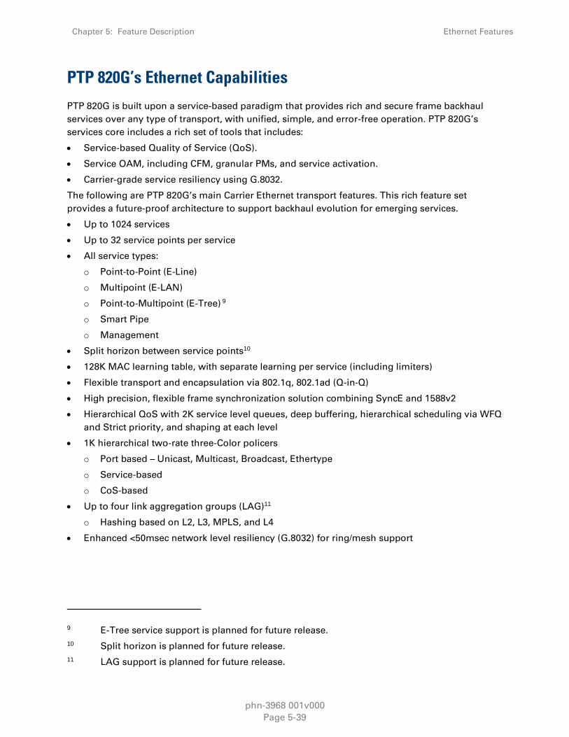
Chapter 5: Feature Description Ethernet Features
phn-3968 001v000
Page 5-39
PTP 820G’s Ethernet Capabilities
PTP 820G is built upon a service-based paradigm that provides rich and secure frame backhaul
services over any type of transport, with unified, simple, and error-free operation. PTP 820G’s
services core includes a rich set of tools that includes:
Service-based Quality of Service (QoS).
Service OAM, including CFM, granular PMs, and service activation.
Carrier-grade service resiliency using G.8032.
The following are PTP 820G’s main Carrier Ethernet transport features. This rich feature set
provides a future-proof architecture to support backhaul evolution for emerging services.
Up to 1024 services
Up to 32 service points per service
All service types:
o Point-to-Point (E-Line)
o Multipoint (E-LAN)
o Point-to-Multipoint (E-Tree) 9
o Smart Pipe
o Management
Split horizon between service points10
128K MAC learning table, with separate learning per service (including limiters)
Flexible transport and encapsulation via 802.1q, 802.1ad (Q-in-Q)
High precision, flexible frame synchronization solution combining SyncE and 1588v2
Hierarchical QoS with 2K service level queues, deep buffering, hierarchical scheduling via WFQ
and Strict priority, and shaping at each level
1K hierarchical two-rate three-Color policers
o Port based – Unicast, Multicast, Broadcast, Ethertype
o Service-based
o CoS-based
Up to four link aggregation groups (LAG)11
o Hashing based on L2, L3, MPLS, and L4
Enhanced <50msec network level resiliency (G.8032) for ring/mesh support
9 E-Tree service support is planned for future release.
10 Split horizon is planned for future release.
11 LAG support is planned for future release.
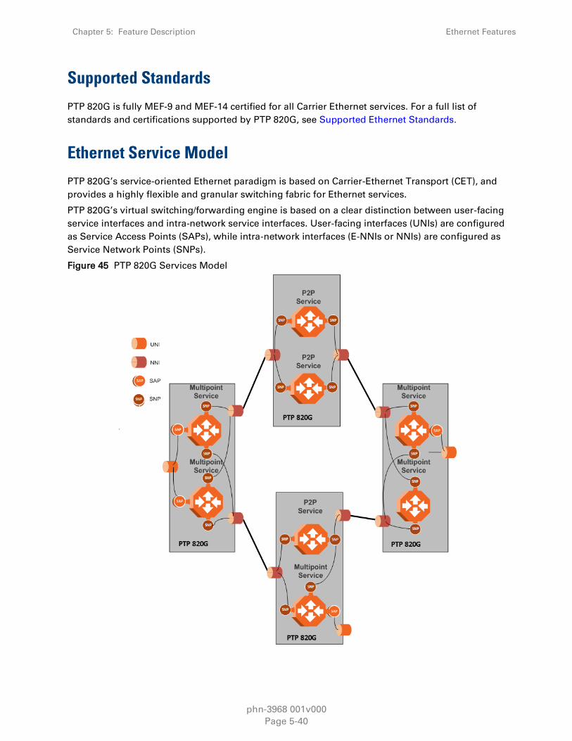
Chapter 5: Feature Description Ethernet Features
phn-3968 001v000
Page 5-40
Supported Standards
PTP 820G is fully MEF-9 and MEF-14 certified for all Carrier Ethernet services. For a full list of
standards and certifications supported by PTP 820G, see Supported Ethernet Standards.
Ethernet Service Model
PTP 820G’s service-oriented Ethernet paradigm is based on Carrier-Ethernet Transport (CET), and
provides a highly flexible and granular switching fabric for Ethernet services.
PTP 820G’s virtual switching/forwarding engine is based on a clear distinction between user-facing
service interfaces and intra-network service interfaces. User-facing interfaces (UNIs) are configured
as Service Access Points (SAPs), while intra-network interfaces (E-NNIs or NNIs) are configured as
Service Network Points (SNPs).
Figure 45 PTP 820G Services Model

Chapter 5: Feature Description Ethernet Features
phn-3968 001v000
Page 5-41
The PTP 820G services core provides for fully flexible C-VLAN and S-VLAN encapsulation, with a
full range of classification, preservation, and translation options available. Service security and
isolation is provided without limiting the C-VLAN reuse capabilities of different customers.
Users can define up to 1024 services on a single PTP 820G. Each service constitutes a virtual
bridge that defines the connectivity and behavior among the network element interfaces for the
specific virtual bridge. In addition to user-defined services, PTP 820G contains a pre-defined
management service (Service ID 1025). If needed, users can activate the management service and
use it for in-band management.
To define a service, the user must configure virtual connections among the interfaces that belong
to the service. This is done by configuring service points (SPs) on these interfaces.
A service can hold up to 32 service points. A service point is a logical entity attached to a physical
or logical interface. Service points define the movement of frames through the service. Each
service point includes both ingress and egress attributes.
Note
Management services can hold up to 30 SPs.
The following figure illustrates the PTP 820G services model, with traffic entering and leaving the
network element. PTP 820G’s switching fabric is designed to provide a high degree of flexibility in
the definition of services and the treatment of data flows as they pass through the switching fabric.
Figure 46 PTP 820G Services Core
P2P Service
Multipoint Service
SAPSP SAPSP
SAPSPSAPSP
SAPSP SAPSP
Port 1
Port 2
Port 4
Port 4
Port 9
C-tag=3000C-tag=20
Untag
C-tag=20
C-tag=1000 to 2000
C-tag=10
SC-tag=2,3
S-tag=200
Smart Pipe Service
SAPSP SAPSP
SAPSP SAPSP
Port 3
Port 4
Port 8
Port 7
Port 5
Port 6

Chapter 5: Feature Description Ethernet Features
phn-3968 001v000
Page 5-42
Frame Classification to Service Points and Services
Each arriving frame is classified to a specific service point, based on a key that consists of:
The Interface ID of the interface through which the frame entered the PTP 820G.
The frame’s C-VLAN and/or S-VLAN tags.
If the classification mechanism finds a match between the key of the arriving frame and a specific
service point, the frame is associated to the specific service to which the service point belongs.
That service point is called the ingress service point for the frame, and the other service points in
the service are optional egress service points for the frame. The frame is then forwarded from the
ingress service point to an egress service point by means of flooding or dynamic address learning
in the specific service. Services include a MAC entry table of up to 131,072 entries, with a global
aging timer and a maximum learning limiter that are configurable per-service.
Figure 47 PTP 820G Services Flow
Port
Port Port
P2P Service
User Port
User Port Network
Port
SAPSNPSAPSAP
SAPSNPSAPSAP
SNP
SNP
SAP
SAP
P2P Service
Multipoint Service
GE/FE
GE/FE
Port
User Port
GE/FE
Port
NetworkPort
EthernetRadio
Ethernet traffic
EthernetRadio
Ethernet traffic
Service Types
PTP 820G supports the following service types:
Point-to-Point Service (P2P)
MultiPoint Service (MP)
Management Service
Point-to-Multipoint Service (E-Tree)
Note
E-Tree service support is planned for future release.

Chapter 5: Feature Description Ethernet Features
phn-3968 001v000
Page 5-43
Point to Point Service (P2P)
Point-to-point services are used to provide connectivity between two interfaces of the network
element. When traffic ingresses via one side of the service, it is immediately directed to the other
side, according to ingress and egress tunneling rules. This type of service contains exactly two
service points and does not require MAC address-based learning or forwarding. Since the route is
clear, the traffic is tunneled from one side of the service to the other and vice versa.
The following figure illustrates a P2P service.
Figure 48 Point-to-Point Service
SAPSP
P2P Service
SAPSP
SAPSP SAPSP
Port 1
Port 2
Port 3
Port 4
Port 5
Port 6
P2P Service
P2P services provide the building blocks for network services such as E-Line EVC (EPL and EVPL
EVCs) and port-based services (Smart Pipe).
Multipoint Service (MP)
Multipoint services are used to provide connectivity between two or more service points. When
traffic ingresses via one service point, it is directed to one of the service points in the service, other
than the ingress service point, according to ingress and egress tunneling rules, and based on the
learning and forwarding mechanism. If the destination MAC address is not known by the learning
and forwarding mechanism, the arriving frame is flooded to all the other service points in the
service except the ingress service point.
The following figure illustrates a Multipoint service.

Chapter 5: Feature Description Ethernet Features
phn-3968 001v000
Page 5-44
Figure 49 Multipoint Service
SAPSP
Multipoint Service
Port 1
Port 2
Port 3
Port 4
Port 5
Port 6
SAPSP
SAPSPSAPSP
SAPSP
Multipoint services provide the building blocks for network services such as E-LAN EVCs (EP-LAN
and EVP-LAN EVCs), and for E-Line EVCs (EPL and EVPL EVCs) in which only two service points are
active. In such a case, the user can disable MAC address learning in the service points to conserve
system resources.
Learning and Forwarding Mechanism
PTP 820G can learn up to 131,072 Ethernet source MAC addresses. PTP 820G performs learning
per service in order to enable the use of 1024 virtual bridges in the network element. If necessary
due to security issues or resource limitations, users can limit the size of the MAC forwarding table.
The maximum size of the MAC forwarding table is configurable per service in granularity of 16
entries.
When a frame arrives via a specific service point, the learning mechanism checks the MAC
forwarding table for the service to which the service point belongs to determine whether that MAC
address is known to the service. If the MAC address is not found, the learning mechanism adds it
to the table under the specific service.
In parallel with the learning process, the forwarding mechanism searches the service’s MAC
forwarding table for the frame’s destination MAC address. If a match is found, the frame is
forwarded to the service point associated with the MAC address. If not, the frame is flooded to all
service points in the service.
The following table illustrates the operation of the learning and forwarding mechanism.

Chapter 5: Feature Description Ethernet Features
phn-3968 001v000
Page 5-45
Table 8 Ethernet Services Learning and Forwarding
MAC Forwarding Table
Input Key for learning / forwarding
(search) operation Result Entry type
Service ID MAC address Service Point
13 00:34:67:3a:aa:10 15 dynamic
13 00:0a:25:33:22:12 31 dynamic
28 00:0a:25:11:12:55 31 static
55 00:0a:25:33:22:12 15 dynamic
55 00:c3:20:57:14:89 31 dynamic
55 00:0a:25:11:12:55 31 dynamic
In addition to the dynamic learning mechanism, users can add static MAC addresses for static
routing in each service. These user entries are not considered when determining the maximum
size of the MAC forwarding table.
Users can manually clear the dynamic entries from the MAC forwarding table. The MAC
forwarding table can be cleared on three levels:
Global Switch Flush – All dynamic entries for all services are erased.
Service Flush – All dynamic entries for a specific service are flushed.12
Port Flush – All dynamic entries associated with a specific interface are erased. 13
Users can also delete static entries per service.
The system also provides an automatic flush process. An entry is erased from the table as a result
of:
The global aging time expires for the entry.
Loss of carrier occurs on the interface with which the entry is associated.
Resiliency protocols, such as MSTP or G.8032.
Management Service (MNG)
The management service is a multipoint service that connects the two local management ports,
the network element host CPU, and the traffic ports into a single service. The service behavior is
same as the Multipoint service behavior.
12 The Service Flush option is planned for future release.
13 The Port Flush option is planned for future release.

Chapter 5: Feature Description Ethernet Features
phn-3968 001v000
Page 5-46
The management service is pre-defined in the system, with Service ID 1025. The pre-defined
management service has a single service point that connects the service to the network element
host CPU and the two local management interfaces. To configure in-band management over
multiple network elements, the user must connect the management service to the network by
adding a service point on an interface that provides the required network connectivity.
Users can modify the attributes of the management service, but cannot delete it. The CPU service
point is read-only and cannot be modified. The local management ports are also connected to the
service, but their service points are not visible to users. The first management interface is enabled
by default. The second management interface must be manually enabled by the user. The
management ports can be used to manage the network element or to access a remote network
element. They can also be used to manage third-party devices. Users can enable or disable these
ports.
The following figure illustrates a management service.
Figure 50 Management Service
SAPSP
Management ServicePort 1
Port 2
Port 3
SAPSP
SAPSPSAPSP
SAPSP
Local Management 1
Local Management 2
Port 4
Port 5
Port 6
SAPSP
CPU
Management services can provide building blocks for network services such as E-LAN EVCs (EP-
LAN and EVP-LAN), as well as E-Line EVCs (EPL and EVPL EVCs) in which only two service points
are active.
Service Attributes
PTP 820G services have the following attributes:
Service ID – A running number from 1 to 1024 that identifies the service. The user must select the
Service ID upon creating the service. The Service ID cannot be edited after the service has been
created. Service ID 1025 is used for the pre-defined Management service.

Chapter 5: Feature Description Ethernet Features
phn-3968 001v000
Page 5-47
Service Type – Determines the specific functionality that will be provided for Ethernet traffic using
the service. For example, a Point-to-Point service provides traffic forwarding between two service
points, with no need to learn a service topology based on source and destination MAC addresses.
A Multipoint service enables operators to create an E-LAN service that includes several service
points.
Service Admin Mode – Defines whether or not the service is functional, i.e., able to receive and
transmit traffic. When the Service Admin Mode is set to Operational, the service is fully functional.
When the Service Admin Mode is set to Reserved, the service occupies system resources but is
unable to transmit and receive data.
EVC-ID – The Ethernet Virtual Connection ID (end-to-end). This parameter does not affect the
network element’s behavior, but is used by the NMS for topology management.
EVC Description – The Ethernet Virtual Connection description. This parameter does not affect the
network element’s behavior, but is used by the NMS for topology management.
Maximum Dynamic MAC Address Learning per Service – Defines the maximum number of
dynamic Ethernet MAC address that the service can learn. This parameter is configured with a
granularity of 16, and only applies to dynamic, not static, MAC addresses.
Static MAC Address Configuration – Users can add static entries to the MAC forwarding table. The
global aging time does not apply to static entries, and they are not counted with respect to the
Maximum Dynamic MAC Address Learning. It is the responsibility of the user not to use all the
131,072 entries in the table if the user also wants to utilize dynamic MAC address learning.
CoS Mode – Defines whether the service inherits ingress classification decisions made at previous
stages or overwrites previous decisions and uses the default CoS defined for the service. For more
details on PTP 820G’s hierarchical classification mechanism, see Classification on page 5-62.
Default CoS – The default CoS value at the service level. If the CoS Mode is set to overwrite
previous classification decisions, this is the CoS value used for frames entering the service.
xSTP Instance (0-46, 4095) – The spanning tree instance ID to which the service belongs. The
service can be a traffic engineering service (instance ID 4095) or can be managed by the xSTP
engines of the network element.
Service Points
Service points are logical entities attached to the interfaces that make up the service. Service
points define the movement of frames through the service. Without service points, a service is
simply a virtual bridge with no ingress or egress interfaces.
PTP 820G supports several types of service points:
Management (MNG) Service Point – Only used for management services. The following figure
shows a management service used for in-band management among four network elements in
a ring. In this example, each service contains three MNG service points, two for East-West
management connectivity in the ring, and one serving as the network gateway.

Chapter 5: Feature Description Ethernet Features
phn-3968 001v000
Page 5-48
Figure 51 Management Service and its Service Points
MNG
MNG
MNG
MNG MNG
MNG
MNG
MNG
MNG
MNG
MNGMNG
Service Access Point (SAP) Service Point – An SAP is equivalent to a UNI in MEF terminology
and defines the connection of the user network with its access points. SAPs are used for Point-
to-Point and Multipoint traffic services.
Service Network Point (SNP) Service Point – An SNP is equivalent to an NNI or E-NNI in MEF
terminology and defines the connection between the network elements in the user network.
SNPs are used for Point-to-Point and Multipoint traffic services.
The following figure shows four network elements in ring. An MP Service with three service points
provides the connectivity over the network. The SNPs provide the connectivity among the network
elements in the user network while the SAPs provide the access points for the network.
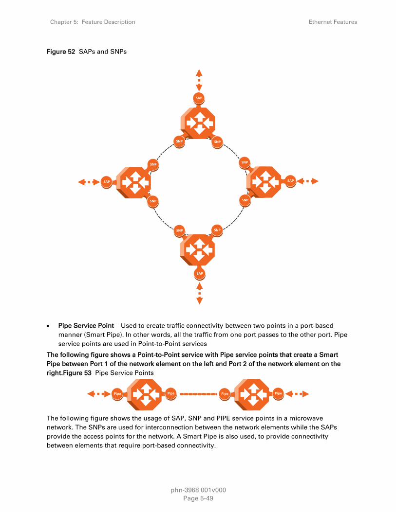
Chapter 5: Feature Description Ethernet Features
phn-3968 001v000
Page 5-49
Figure 52 SAPs and SNPs
SAP
SNP
SNP
SNP SNP
SAP
SNP
SAP
SNP
SAP
SNPSNP
Pipe Service Point – Used to create traffic connectivity between two points in a port-based
manner (Smart Pipe). In other words, all the traffic from one port passes to the other port. Pipe
service points are used in Point-to-Point services
The following figure shows a Point-to-Point service with Pipe service points that create a Smart
Pipe between Port 1 of the network element on the left and Port 2 of the network element on the
right.Figure 53 Pipe Service Points
Pipe Pipe Pipe Pipe
The following figure shows the usage of SAP, SNP and PIPE service points in a microwave
network. The SNPs are used for interconnection between the network elements while the SAPs
provide the access points for the network. A Smart Pipe is also used, to provide connectivity
between elements that require port-based connectivity.

Chapter 5: Feature Description Ethernet Features
phn-3968 001v000
Page 5-50
Figure 54 SAP, SNP and Pipe Service Points in a Microwave Network
SAP
SAP
SAP
SAP
SNP
SNP
SNP
SNP
SNP
SNP
SNP
SNP
SNPSNP
SNP
Base Station
Microwave Network
NOC
Fiber Aggregation Network
SAP
PIPE
PIPE
SNP
The following table summarizes the service point types available per service type.
Table 9 Service Point Types per Service Type
Service point type
MNG SAP SNP Pipe
Service
Type
Point-to-Point Yes No No No
Multipoint No Yes Yes Yes
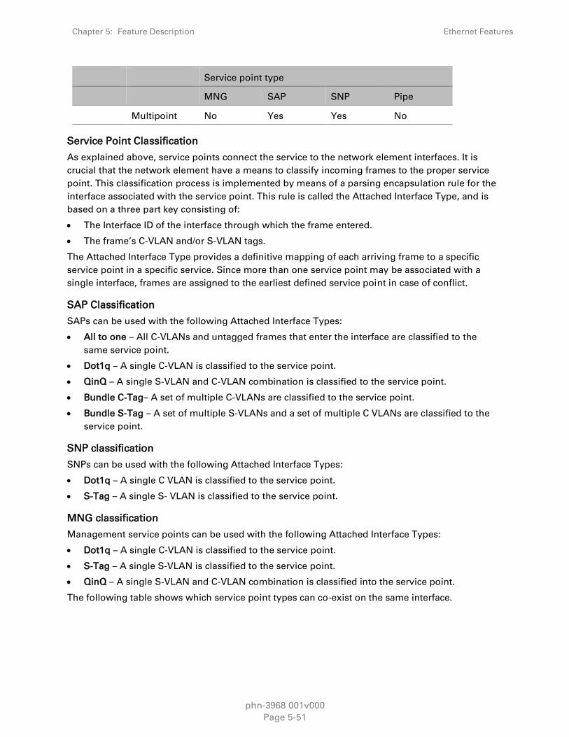
Chapter 5: Feature Description Ethernet Features
phn-3968 001v000
Page 5-51
Service point type
MNG SAP SNP Pipe
Multipoint No Yes Yes No
Service Point Classification
As explained above, service points connect the service to the network element interfaces. It is
crucial that the network element have a means to classify incoming frames to the proper service
point. This classification process is implemented by means of a parsing encapsulation rule for the
interface associated with the service point. This rule is called the Attached Interface Type, and is
based on a three part key consisting of:
The Interface ID of the interface through which the frame entered.
The frame’s C-VLAN and/or S-VLAN tags.
The Attached Interface Type provides a definitive mapping of each arriving frame to a specific
service point in a specific service. Since more than one service point may be associated with a
single interface, frames are assigned to the earliest defined service point in case of conflict.
SAP Classification
SAPs can be used with the following Attached Interface Types:
All to one – All C-VLANs and untagged frames that enter the interface are classified to the
same service point.
Dot1q – A single C-VLAN is classified to the service point.
QinQ – A single S-VLAN and C-VLAN combination is classified to the service point.
Bundle C-Tag– A set of multiple C-VLANs are classified to the service point.
Bundle S-Tag – A set of multiple S-VLANs and a set of multiple C VLANs are classified to the
service point.
SNP classification
SNPs can be used with the following Attached Interface Types:
Dot1q – A single C VLAN is classified to the service point.
S-Tag – A single S- VLAN is classified to the service point.
MNG classification
Management service points can be used with the following Attached Interface Types:
Dot1q – A single C-VLAN is classified to the service point.
S-Tag – A single S-VLAN is classified to the service point.
QinQ – A single S-VLAN and C-VLAN combination is classified into the service point.
The following table shows which service point types can co-exist on the same interface.

Chapter 5: Feature Description Ethernet Features
phn-3968 001v000
Page 5-52
Table 10 Service Point Types that can Co-Exist on the Same Interface
MNG SP SAP SP SNP SP Pipe SP
MNG SP Only one MNG
SP is allowed per
interface.
Yes Yes Yes
SAP SP Yes Yes No No
SNP SP Yes No Yes No
PIPE SP Yes No No Only one Pipe SP
is allowed per
interface.
The following table shows in more detail which service point – Attached Interface Type
combinations can co-exist on the same interface
Table 11 Attached Interface Type combinations SAP
SP Type SAP
SP
Type
Attached
Interface Type 802.1q
Bundle
C-Tag
Bundle
S-Tag All to One QinQ
SAP
802.1q Yes Yes No No No
Bundle C-Tag Yes Yes No No No
Bundle S-Tag No No Yes No Yes
All to One No No No
Only 1 All
to One SP
Per
Interface
No
QinQ No No Yes No Yes
SNP 802.1q No No No No No
S-Tag No No No No No
Pipe 802.1q
Only for
P2P Service
Only for
P2P Service No No No
S-Tag No No No No No
MNG
802.1q Yes Yes No No No
QinQ No No Yes No Yes
S-Tag No No No No No

Chapter 5: Feature Description Ethernet Features
phn-3968 001v000
Page 5-53
Table 12 Attached Interface Type combinations SNP Pipe MNG
Service Point Attributes
As described above, traffic ingresses and egresses the service via service points. The service point
attributes are divided into two types:
Ingress Attributes – Define how frames are handled upon ingress, e.g., policing and MAC
address learning.
Egress Attributes – Define how frames are handled upon egress, e.g., preservation of the
ingress CoS value upon egress, VLAN swapping.
SP Type SNP Pipe MNG
SP
Type
Attached
Interface
Type
802.1q S-Tag 802.1q S-Tag 802.1q QinQ S-Tag
SAP
802.1q No No
Only for
P2P
Service
No Yes No No
Bundle
C-Tag No No
Only for
P2P
Service
No Yes No No
Bundle
S-Tag No No No No No Yes No
All to One No No No No No No No
QinQ No No No No No Yes No
SNP
802.1q Yes No
Only for
P2P
Service
No Yes No No
S-Tag No Yes No
Only for
P2P
Service
No No Yes
Pipe
802.1q
Only for
P2P
Service
No
Only one
Pipe SP
Per
Interface
No Yes No No
S-Tag No
Only for
P2P
Service
No
Only one
Pipe SP
Per
Interface
No No Yes
MNG
802.1q Yes No Yes No No No No
QinQ No No No No No No No
S-Tag No Yes No Yes No No No

Chapter 5: Feature Description Ethernet Features
phn-3968 001v000
Page 5-54
The following figure shows the ingress and egress path relationship on a point-to-point service
path. When traffic arrives via port 1, the system handles it using service point 1 ingress attributes
then forwards it to service point 2 and handles it using the SP2 egress attributes:
Figure 55 Service Path Relationship on Point-to-Point Service Path
Ingress
Egress
SP1
Ingress
Egress
SP2
Port 1 Port 2
Service points have the following attributes:
General Service Point Attributes
Service Point ID – Users can define up to 32 service points per service, except for management
services which are limited to 30 service points in addition to the pre-defined management system
service point.
Service Point Name – A descriptive name, which can be up to 20 characters.
Service Point Type – The type of service point, as described above.
S-VLAN Encapsulation – The S-VLAN ID associated with the service point.
C-VLAN Encapsulation – The C-VLAN ID associated with the service point.
Attached C VLAN – For service points with an Attached Interface Type of Bundle C-Tag, this
attribute is used to create a list of C-VLANs associated with the service point.
Attached S-VLAN – For service points with an Attached Interface Type of Bundle S-Tag, this
attribute is used to create a list of S-VLANs associated with the service point.
Ingress Service Point Attributes
The ingress attributes are attributes that operate upon frames when they ingress via the service
point.
Attached Interface Type – The interface type to which the service point is attached, as
described above. Permitted values depend on the service point type.
Learning Administration – Enables or disables MAC address learning for traffic that ingresses
via the service point. This option enables users to enable or disable MAC address learning for
specific service points.
Allow Broadcast – Determines whether to allow frames to ingress the service via the service
point when the frame has a broadcast destination MAC address.
Allow Flooding – Determines whether incoming frames with unknown MAC addresses are
forwarded to other service points via flooding.
CoS Mode – Determines whether the service point preserves the CoS decision made at the
interface level, overwrites the CoS with the default CoS for the service point.

Chapter 5: Feature Description Ethernet Features
phn-3968 001v000
Page 5-55
Default CoS – The service point CoS. If the CoS Mode is set to overwrite the CoS decision
made at the interface level, this is the CoS value assigned to frames that ingress the service
point.
Token Bucket Profile – This attribute can be used to attach a rate meter profile to the service
point. Permitted values are 1– 250. 14
CoS Token Bucket Profile – This attribute can be used to attach a rate meter profile to the
service point at the CoS level. Users can define a rate meter for each of the eight CoS values of
the service point. Permitted values are 1-250 for CoS 0–7.15
CoS Token Bucket Admin – Enables or disables the rate meter at the service point CoS level.16
Egress Service Point Attributes
The egress attributes are attributes that operate upon frames egressing via the service point.
C-VLAN ID Egress Preservation – If enabled, C-VLAN frames egressing the service point retain
the same C-VLAN ID they had when they entered the service.
C-VLAN CoS Egress Preservation – If enabled, the C-VLAN CoS value of frames egressing the
service point is the same as the value when the frame entered the service.
S-VLAN CoS egress Preservation – If enabled, the S-VLAN CoS value of frames egressing the
service point is the same as the value when the frame entered the service.
Marking – Marking refers to the ability to overwrite the outgoing priority bits and Color of the
outer VLAN of the egress frame, either the C-VLAN or the S-VLAN. If marking is enabled, the
service point overwrites the outgoing priority bits and Color of the outer VLAN of the egress
frame. Marking mode is only relevant if either the outer frame is S-VLAN and S-VLAN CoS
preservation is disabled, or the outer frame is C-VLAN and C-VLAN CoS preservation is
disabled. When marking is enabled and active, marking is performed according to global
mapping tables that map the 802.1p-UP bits and the DEI or CFI bit to a defined CoS and Color
value.
Service Bundle ID – This attribute can be used to assign one of the available service bundles
from the H-QoS hierarchy queues to the service point. This enables users to personalize the
QoS egress path. For details, see Standard QoS and Hierarchical QoS (H-QoS) on page 5-75.
Ethernet Interfaces
The PTP 820G switching fabric distinguishes between physical interfaces and logical interfaces.
Physical and logical interfaces serve different purposes in the switching fabric.
The concept of a physical interface refers to the physical characteristics of the interface, such as
speed, duplex, auto-negotiation, master/slave, and standard RMON statistics.
14 This feature is planned for future release.
15 This feature is planned for future release.
16 This feature is planned for future release.

Chapter 5: Feature Description Ethernet Features
phn-3968 001v000
Page 5-56
A logical interface can consist of a single physical interface or a group of physical interfaces that
share the same function. Examples of the latter are protection groups and link aggregation groups.
Switching and QoS functionality are implemented on the logical interface level.
It is important to understand that the PTP 820G switching fabric regards all traffic interfaces as
regular physical interfaces, distinguished only by the media type the interface uses, e.g., RJ-45,
SFP, or Radio.
From the user’s point of view, the creation of the logical interface is simultaneous with the creation
of the physical interface. For example, when the user enables a radio interface, both the physical
and the logical radio interface come into being at the same time.
Once the interface is created, the user configures both the physical and the logical interface. In
other words, the user configures the same interface on two levels, the physical level and the
logical level.
The following figure shows physical and logical interfaces in a one-to-one relationship in which
each physical interface is connected to a single logical interface, without grouping.
Figure 56 Physical and Logical Interfaces
SP
SP SP
SPPhysical Interface 2
Physical Interface 1 Logical Interface
Logical Interface
Service
Physical Interface 3
Physical Interface 4
Logical Interface
Logical Interface
Note
For simplicity only, this figure represents a uni-directional rather than a bi-directional
traffic flow.
The next figure illustrates the grouping of two or more physical interfaces into a logical interface, a
link aggregation group (LAG) in this example. The two physical interfaces on the ingress side send
traffic into a single logical interface. The user configures each physical interface separately, and
configures the logical interface as a single logical entity. For example, the user might configure
each physical interface to 100 mbps, full duplex, with auto-negotiation off. On the group level, the
user might limit the group to a rate of 200 mbps by configuring the rate meter on the logical
interface level.
When physical interfaces are grouped into a logical interface, PTP 820G also shows standard
RMON statistics for the logical interface, i.e., for the group. This information enables users to
determine the cumulative statistics for the group, rather than having to examine the statistics for
each interface individually.

Chapter 5: Feature Description Ethernet Features
phn-3968 001v000
Page 5-57
Figure 57 Grouped Interfaces as a Single Logical Interface on Ingress Side
Logical Interface
LAG
SP
SP SP
SP
Physical Interface 2
Physical Interface 1
Service
Physical Interface 3
Physical Interface 4
Logical Interface
Logical Interface
Note
For simplicity only, this figure represents a uni-directional rather than a bi-directional
traffic flow.
The following figure shows the logical interface at the egress side. In this case, the user can
configure the egress traffic characteristics, such as scheduling, for the group as a whole as part of
the logical interface attributes.
Figure 58 Grouped Interfaces as a Single Logical Interface on Egress Side
LAG
SP
SP SP
SPPhysical Interface 4
Physical Interface 3
Service
Logical Interface
Physical Interface 2
Physical Interface 1 Logical Interface
Logical Interface
Note
For simplicity only, this figure represents a uni-directional rather than a bi-directional
traffic flow.
Physical Interfaces
The physical interfaces refer to the real traffic ports (layer 1) that are connected to the network. The
Media Type attribute defines the Layer 1 physical traffic interface type, which can be:
Radio interface.
RJ-45 or SFP for an Ethernet interface.
TDM for a DS1 interface.

Chapter 5: Feature Description Ethernet Features
phn-3968 001v000
Page 5-58
Physical Interface Attributes
The following physical interface parameters can be configured by users:
Admin – Enables or disables the physical interface. This attribute is set via the Interface
Manager section of the Web EMS.
Auto Negotiation – Enables or disables auto-negotiation on the physical interface. Auto
Negotiation is always off for radio, SFP, and TDM interfaces.
Speed and Duplex – The physical interface speed and duplex mode. Permitted values are:
o Ethernet RJ-45 interfaces: 10Mbps HD, 10Mbps FD, 100Mbps HD, 100Mbps FD, and
1000Mpbs FD.
o Ethernet SFP interfaces: Only 1000FD is supported
o Radio and TDM interfaces: The parameter is read-only and set by the system to 1000FD.
Flow Control – The physical port flow control capability. Permitted values are: Symmetrical
Pause and/or Asymmetrical Pause. This parameter is only relevant in Full Duplex mode.17
Media Type – The physical interface Layer 1 media type. This attribute is only relevant for
Ethernet traffic ports (RJ-45 or SFP). Permitted values are Auto Detect, RJ-45, and SFP. When
Auto Detect is selected, the system detects whether the optical or electrical port is being used.
Auto Detect can only be used when the interface speed is set to 1000 Mbps.
IFG – The physical port Inter-frame gap. Although users can modify the IFG field length, it is
strongly recommended not to modify the default value of 12 bytes without a thorough
understanding of how the modification will impact traffic. Permitted values are 6 to 15 bytes.
Preamble – The physical port preamble value. Although users can modify the preamble field
length, it is strongly recommended not to modify the default values of 8 bytes without a
thorough understanding of how the modification will impact traffic. Permitted values are 6 to
15 bytes.
Interface description – A text description of the interface, up to 40 characters.
The following read-only physical interface status parameters can be viewed by users:
Operational State – The operational state of the physical interface (Up or Down).
Actual Speed and Duplex – The actual speed and duplex value for the Ethernet link as agreed
by the two sides of the link after the auto negotiation process.
Actual Flow Control State – The actual flow control state values for the Ethernet link as agreed
by the two sides after the auto negotiation process.
Actual Physical Mode (only relevant for RJ-45 interfaces) – The actual physical mode (master
or slave) for the Ethernet link, as agreed by the two sides after the auto negotiation process.
Ethernet Statistics (RMON)
The PTP PTP 820G platform stores and displays statistics in accordance with RMON and RMON2
standards.
The following transmit statistic counters are available:
Transmitted bytes (not including preamble) in good or bad frames. Low 32 bits.
17 This functionality is planned for future release.

Chapter 5: Feature Description Ethernet Features
phn-3968 001v000
Page 5-59
Transmitted bytes (not including preamble) in good or bad frames. High 32 bits.
Transmitted frames (good or bad)
Multicast frames (good only)
Broadcast frames (good only)
Control frames transmitted
Pause control frame transmitted
FCS error frames
Frame length error
Oversized frames – frames with length > 1518 bytes (1522 bytes for VLAN-tagged frames)
without errors
Undersized frames (good only)
Fragments frames (undersized bad)
Jabber frames – frames with length > 1518 bytes (1522 for VLAN-tagged frames) with errors
Frames with length 64 bytes, good or bad
Frames with length 65-127 bytes, good or bad
Frames with length 128-255 bytes, good or bad
Frames with length 256-511 bytes, good or bad
Frames with length 512-1023 bytes, good or bad.
Frames with length 1024-1518 bytes, good or bad
Frames with length 1519-1522 bytes, good or bad
The following receive statistic counters are available:
Received bytes (not including preamble) in good or bad frames. Low 32 bits.
Received bytes (not including preamble) in good or bad frames. High 32 bits.
Received frames (good or bad)
Multicast frames (good only)
Broadcast frames (good only)
Control frames received
Pause control frame received
FCS error frames
Frame length error
Code error
Counts oversized frames – frames with length > 1518 bytes (1522 bytes for VLAN-tagged
frames) without errors and frames with length > MAX_LEN without errors
Undersized frames (good only)
Fragments frames (undersized bad)
Counts jabber frames – frames with length > 1518 bytes (1522 for VLAN-tagged frames) with
errors
Frames with length 64 bytes, good or bad

Chapter 5: Feature Description Ethernet Features
phn-3968 001v000
Page 5-60
Frames with length 65-127 bytes, good or bad
Frames with length 128-255 bytes, good or bad
Frames with length 256-511 bytes, good or bad
Frames with length 512-1023 bytes, good or bad
Frames with length 1024-1518 bytes, good or bad
VLAN-tagged frames with length 1519-1522 bytes, good or bad
Frames with length > MAX_LEN without errors
Frames with length > MAX_LEN with errors
Logical Interfaces
A logical interface consists of one or more physical interfaces that share the same traffic ingress
and egress characteristics. From the user’s point of view, it is more convenient to define interface
behavior for the group as a whole than for each individual physical interface that makes up the
group. Therefore, classification, QoS, and resiliency attributes are configured and implemented on
the logical interface level, in contrast to attributes such as interface speed and duplex mode, which
are configured on the physical interface level.
It is important to understand that the user relates to logical interfaces in the same way in both a
one-to-one scenario in which a single physical interface corresponds to a single logical interface,
and a grouping scenario such as a link aggregation group or a radio protection group, in which
several physical interfaces correspond to a single logical interface.
The following figure illustrates the relationship of a 1+1 HSB radio protection group to the
switching fabric. From the point of view of the user configuring the logical interface attributes, the
fact that there are two radios is not relevant. The user configures and manages the logical interface
just as if it represented a single 1+0 radio.
Figure 59 Relationship of Logical Interfaces to the Switching Fabric
SP
SP SP
SPService
Radio Protection Group 1
Radio Interface 1
Radio Interface 2
HSB
Physical Interface 1
Physical Interface 2
Logical Interface Physical Interface 3
Logical Interface Physical Interface 4
Logical Interface Attributes
The following logical interface attributes can be configured by users:

Chapter 5: Feature Description Ethernet Features
phn-3968 001v000
Page 5-61
General Attributes
Traffic Flow Administration – Enables traffic via the logical interface. This attribute is useful
when the user groups several physical interfaces into a single logical interface. The user can
enable or disable traffic to the group using this parameter.
Ingress Path Classification at Logical Interface Level
These attributes represent part of the hierarchical classification mechanism, in which the logical
interface is the lowest point in the hierarchy.
VLAN ID – Users can specify a specific CoS and Color for a specific VLAN ID. In the case of
double-tagged frames, the match must be with the frame’s outer VLAN. Permitted values are
CoS 0 to 7 and Color Green or Yellow per VLAN ID. This is the highest classification priority on
the logical interface level, and overwrites any other classification criteria at the logical interface
level.
802.1p Trust Mode – When this attribute is set to Trust mode and the arriving packet is 802.1Q
or 802.1AD, the interface performs QoS and Color classification according to user-configurable
tables for 802.1q UP bit (C-VLAN frames) or 802.1AD UP bit (S-VLAN frames) to CoS and Color
classification.
IP DSCP Trust Mode –When this attribute is set to Trust mode and the arriving packet has IP
priority bits, the interface performs QoS and Color classification according to a user-
configurable DSCP bit to CoS and Color classification table. 802.1p classification has priority
over DSCP Trust Mode, so that if a match is found on the 802.1p level, DSCP bits are not
considered.
MPLS Trust Mode – When this attribute is set to Trust mode and the arriving packet has MPLS
EXP priority bits, the interface performs QoS and Color classification according to a user-
configurable MPLS EXP bit to CoS and Color classification table. Both 802.1p and DSCP
classification have priority over MPLS Trust Mode, so that if a match is found on either the
802.1p or DSCP levels, MPLS bits are not considered.
Default CoS – The default CoS value for frames passing through the interface. This value can
be overwritten on the service point and service level. The Color is assumed to be Green.
For more information about classification at the logical interface level, see Logical Interface-Level
Classification on page 5-63.
Ingress Path Rate Meters at Logical Interface Level
Unicast Traffic Rate Meter Admin – Enables or disables the unicast rate meter (policer) on the
logical interface.
Unicast Traffic Rate Meter Profile – Associates the rate meter (policer) with a specific rate
meter (policer) profile.
Multicast Traffic Rate Meter Admin – Enables or disables the multicast rate meter (policer) on
the logical interface.
Multicast Traffic Rate Meter Profile – Associates the rate meter (policer) with a specific rate
meter (policer) profile.
Broadcast Traffic Rate Meter Admin – Enables or disables the broadcast rate meter (policer) on
the logical interface.

Chapter 5: Feature Description Ethernet Features
phn-3968 001v000
Page 5-62
Broadcast Traffic Rate Meter Profile – Associates the rate meter (policer) with a specific rate
meter (policer) profile.
Ethertype 1 Rate Meter Admin – Enables or disables the Ethertype 1 rate meter (policer) on the
logical interface.
Ethertype 1 Rate Meter Profile – Associates the rate meter (policer) with a specific rate meter
(policer) profile.
Ethertype 1 Value – The Ethertype value to which the user wants to apply this rate meter
(policer). The field length is 4 nibbles (for example, 0x0806 - ARP).
Ethertype 2 Rate Meter Admin – Enables or disables the Ethertype 2 rate meter (policer) on the
logical interface.
Ethertype 2 Rate Meter Profile – Associates the rate meter (policer) with a specific rate meter
(policer) profile.
Ethertype 2 Value – The Ethertype value to which the user wants to apply the rate meter
(policer). The field length is 4 nibbles (for example, 0x0806 - ARP).
Ethertype 3 Rate Meter Admin – Enables or disables the Ethertype 3 rate meter (policer) on the
logical interface.
Ethertype 3 Rate Meter Profile – Associates the rate meter (policer) with a specific rate meter
(policer) profile.
Ethertype 3 Value – The Ethertype value to which the user wants to apply the rate meter
(policer). The field length is 4 nibbles (for example, 0x0806 - ARP).
Inline Compensation – The logical interface’s ingress compensation value. The rate meter
(policer) attached to the logical interface uses this value to compensate for Layer 1 non-
effective traffic bytes.
Egress Path Shapers at Logical Interface Level
Logical Port Shaper Profile – Users can assign a single leaky bucket shaper to each interface.
The shaper on the interface level stops traffic from the interface if a specific user-defined peak
information rate (PIR) has been exceeded.18
Outline Compensation – The logical interface’s egress compensation value. Any shaper
attached to this interface, in any layer, uses this value to compensate for Layer 1 non-effective
traffic bytes. Permitted values are even numbers between 0 and 26 bytes. The default value is 0
bytes.
Egress Path Scheduler at Logical Interface Level
Logical Interface Priority Profile – This attribute is used to attach an egress scheduling priority
profile to the logical interface.
18 This attribute is reserved for future use. The current release supports traffic shaping per
queue and per service bundle, which provides the equivalent of shaping per logical interface.

Chapter 5: Feature Description Ethernet Features
phn-3968 001v000
Page 5-63
Logical Port WFQ Profile – This attribute is used to attach an egress scheduling WFQ profile to the
logical interface. The WFQ profile provides a means of allocating traffic among queues with the
same priority.
The following read-only logical interface status parameters can be viewed by users:
Traffic Flow Operational Status – Indicates whether or not the logical interface is currently
functional.
Logical Interface Statistics
RMON Statistics at Logical Interface Level
As discussed in Ethernet Statistics (RMON) on page 5-54, if the logical interface represents a
group, such as a LAG or a 1+1 HSB pair, the PTP 820G platform stores and displays RMON and
RMON2 statistics for the logical interface.
Rate Meter (Policer) Statistics at Logical Interface Level
For the rate meter (policer) at the logical interface level, users can view the following statistics
counters:
Green Frames
Green Bytes
Yellow Frames
Yellow Bytes
Red Frames
Red Bytes
Note
Rate meter (policer) counters are 64 bits wide.
Link Aggregation Groups (LAG)
Link aggregation (LAG) enables users to group several physical interfaces into a single logical
interface bound to a single MAC address. This logical interface is known as a LAG group. Traffic
sent to the interfaces in a LAG group is distributed by means of a load balancing function. PTP
820G uses a distribution function of up to Layer 4 in order to generate the most efficient
distribution among the LAG physical ports, taking into account:
MAC DA and MAC SA
IP DA and IP SA
C-VLAN
S-VLAN
Layer 3 Protocol Field
UDP/TCP Source Port and Destination Port
MPLS Label

Chapter 5: Feature Description Ethernet Features
phn-3968 001v000
Page 5-64
LAG can be used to provide redundancy for Ethernet (line protection). LAG can also be used to
aggregate several interfaces in order to create a wider (aggregate) Ethernet link. For example, LAG
can be used to create a 4 Gbps channel.
Up to four LAG groups can be created.
LAG groups can include interfaces with the following constraints:
Only physical interfaces (including radio interfaces), not logical interfaces, can belong to a LAG
group.
Interfaces can only be added to the LAG group if no services or service points are attached to
the interface.
Any classification rules defined for the interface are overridden by the classification rules
defined for the LAG group.
When removing an interface from a LAG group, the removed interface is assigned the default
interface values.
PTP 820G enables users to select the LAG members without limitations, such as interface speed
and interface type. Proper configuration of a LAG group is the responsibility of the user.
Quality of Service (QoS)
Related topics:
Ethernet Service Model
In-Band Management
Quality of Service (QoS) deals with the way frames are handled within the switching fabric. QoS is
required in order to deal with many different network scenarios, such as traffic congestion, packet
availability, and delay restrictions.
PTP 820G’s personalized QoS enables operators to handle a wide and diverse range of scenarios.
PTP 820G’s smart QoS mechanism operates from the frame’s ingress into the switching fabric until
the moment the frame egresses via the destination port.
QoS capability is very important due to the diverse topologies that exist in today’s network
scenarios. These can include, for example, streams from two different ports that egress via single
port, or a port-to-port connection that holds hundreds of services. In each topology, a customized
approach to handling QoS will provide the best results.
The figure below shows the basic flow of PTP 820G’s QoS mechanism. Traffic ingresses (left to
right) via the Ethernet or radio interfaces, on the “ingress path.” Based on the services model, the
system determines how to route the traffic. Traffic is then directed to the most appropriate output
queue via the “egress path.”
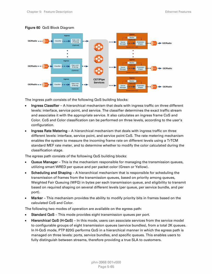
Chapter 5: Feature Description Ethernet Features
phn-3968 001v000
Page 5-65
Figure 60 QoS Block Diagram
(Optional)
Egress
PortScheduler/
Shaper
Standard QoS/ H-QoS
Queue
Manager
Marker
(Optional)
Egress
PortScheduler/
Shaper
Standard QoS/ H-QoS
Queue
Manager
Marker
(Optional)
Egress
PortScheduler/
Shaper
Standard QoS/ H-QoS
Queue
Manager
Marker
CET/Pipe
Services
Rate Limit
(Policing)Classifier
(Optional)
Ingress
Port
Rate Limit
(Policing)Classifier
(Optional)
Ingress
Port
Rate Limit
(Policing)Classifier
(Optional)
Ingress
Port
GE/Radio
GE/Radio
GE/Radio
GE/Radio
GE/Radio
GE/Radio
The ingress path consists of the following QoS building blocks:
Ingress Classifier – A hierarchical mechanism that deals with ingress traffic on three different
levels: interface, service point, and service. The classifier determines the exact traffic stream
and associates it with the appropriate service. It also calculates an ingress frame CoS and
Color. CoS and Color classification can be performed on three levels, according to the user’s
configuration.
Ingress Rate Metering – A hierarchical mechanism that deals with ingress traffic on three
different levels: interface, service point, and service point CoS. The rate metering mechanism
enables the system to measure the incoming frame rate on different levels using a TrTCM
standard MEF rate meter, and to determine whether to modify the color calculated during the
classification stage.
The egress path consists of the following QoS building blocks:
Queue Manager – This is the mechanism responsible for managing the transmission queues,
utilizing smart WRED per queue and per packet color (Green or Yellow).
Scheduling and Shaping – A hierarchical mechanism that is responsible for scheduling the
transmission of frames from the transmission queues, based on priority among queues,
Weighted Fair Queuing (WFQ) in bytes per each transmission queue, and eligibility to transmit
based on required shaping on several different levels (per queue, per service bundle, and per
port).
Marker – This mechanism provides the ability to modify priority bits in frames based on the
calculated CoS and Color.
The following two modes of operation are available on the egress path:
Standard QoS – This mode provides eight transmission queues per port.
Hierarchical QoS (H-QoS) – In this mode, users can associate services from the service model
to configurable groups of eight transmission queues (service bundles), from a total 2K queues.
In H-QoS mode, PTP 820G performs QoS in a hierarchical manner in which the egress path is
managed on three levels: ports, service bundles, and specific queues. This enables users to
fully distinguish between streams, therefore providing a true SLA to customers.

Chapter 5: Feature Description Ethernet Features
phn-3968 001v000
Page 5-66
The following figure illustrates the difference between how standard QoS and H-QoS handle
traffic:
Figure 61 Standard QoS and H-QoS Comparison
Standard QoS
Ethernet
Radio
Eth.
traffic
Service 1
Service 2
Service 3
Voice
Data
Streaming
V
D
S
V
V
D
D
S
S
H-QoS
Ethernet
Radio
Service 1
Service 2
Service 3
V
D
S
Service 1
Service 2
Service 3
V
D
S
V
D
S
QoS on the Ingress Path
Classification
PTP 820G supports a hierarchical classification mechanism. The classification mechanism
examines incoming frames and determines their CoS and Color. The benefit of hierarchical
classification is that it provides the ability to “zoom in” or “zoom out”, enabling classification at
higher or lower levels of the hierarchy. The nature of each traffic stream defines which level of the
hierarchical classifier to apply, or whether to use several levels of the classification hierarchy in
parallel.
The hierarchical classifier consists of the following levels:
Logical interface-level classification
Service point-level classification
Service level classification
The following figure illustrates the hierarchical classification model. In this figure, traffic enters the
system via the port depicted on the left and enters the service via the SAP depicted on the upper
left of the service. The classification can take place at the logical interface level, the service point
level, and/or the service level.

Chapter 5: Feature Description Ethernet Features
phn-3968 001v000
Page 5-67
Figure 62 Hierarchical Classification
SAP
SAP
Service
SAPSNP
SAPSNP
Logical InterfacePort
SNP
SNP
Logical interface level VLAN ID 802.1p-based CoS DSCP-based CoS MPLS EXP-based CoS Default CoS
Service point level Preserve previous decision Default CoS
Service level Default CoS Preserve Service Point Decision
Logical Interface-Level Classification
Logical interface-level classification enables users to configure classification on a single interface
or on a number of interfaces grouped tougher, such as a LAG group.
The classifier at the logical interface level supports the following classification methods, listed
from highest to lowest priority. A higher level classification method supersedes a lower level
classification method:
VLAN ID
802.1p bits.
DSCP bits.
MPLS EXP field.
Default CoS
PTP 820G performs the classification on each frame ingressing the system via the logical interface.
Classification is performed step by step from the highest priority to the lowest priority
classification method. Once a match is found, the classifier determines the CoS and Color decision
for the frame for the logical interface-level.
For example, if the frame is an untagged IP Ethernet frame, a match will not be found until the
third priority level (DSCP priority bits). The CoS and Color values defined for the frame’s DSCP
priority bits will be applied to the frame.
Users can disable some of these classification methods by configuring them as un-trusted. For
example, if 802.1p classification is configured as un-trusted for a specific interface, the
classification mechanism does not perform classification by VLAN UP bits. This is useful, for
example, if the required classification is based on DSCP priority bits.
If no match is found at the logical interface level, the default CoS is applied to incoming frames at
this level. In this case, the Color of the frame is assumed to be Green.
The following figure illustrates the hierarchy of priorities among classification methods, from
highest (on the left) to lowest (on the right) priority.

Chapter 5: Feature Description Ethernet Features
phn-3968 001v000
Page 5-68
Figure 63 Classification Method Priorities
Highest Priority
Lowest Priority
VLAN ID 802.1p DSCP MPLS EXP Default CoS
Interface-level classification is configured as part of the logical interface configuration. For details,
see Ingress Path Classification at Logical Interface Level on page 5-57.
The following tables show the default values for logical interface-level classification. The key
values for these tables are the priority bits of the respective frame encapsulation layers (VLAN, IP,
and MPLS), while the key results are the CoS and Colors calculated for incoming frames. These
results are user-configurable, but it is recommended that only advanced users should modify the
default values.
Table 13 C-VLAN 802.1 UP and CFI Default Mapping to CoS and Color
802.1 UP CFI CoS (configurable) Color (configurable)
0 0 0 Green
0 1 0 Yellow
1 0 1 Green
1 1 1 Yellow
2 0 2 Green
2 1 2 Yellow
3 0 3 Green
3 1 3 Yellow
4 0 4 Green
4 1 4 Yellow
5 0 5 Green
5 1 5 Yellow
6 0 6 Green
6 1 6 Yellow
7 0 7 Green
7 1 7 Yellow

Chapter 5: Feature Description Ethernet Features
phn-3968 001v000
Page 5-69
Table 14 S-VLAN 802.1 UP and DEI Default Mapping to CoS and Color
802.1 UP DEI CoS (Configurable) Color (Configurable)
0 0 0 Green
0 1 0 Yellow
1 0 1 Green
1 1 1 Yellow
2 0 2 Green
2 1 2 Yellow
3 0 3 Green
3 1 3 Yellow
4 0 4 Green
4 1 4 Yellow
5 0 5 Green
5 1 5 Yellow
6 0 6 Green
6 1 6 Yellow
7 0 7 Green
7 1 7 Yellow
Table 15 DSCP Default Mapping to CoS and Color
DSCP DSCP (bin) Description CoS (Configurable) Color (Configurable)
0 (default) 000000 BE (CS0) 0 Green
10 001010 AF11 1 Green
12 001100 AF12 1 Yellow
14 001110 AF13 1 Yellow
18 010010 AF21 2 Green
20 010100 AF22 2 Yellow
22 010110 AF23 2 Yellow
26 011010 AF31 3 Green
28 011100 AF32 3 Yellow
30 011110 AF33 3 Yellow

Chapter 5: Feature Description Ethernet Features
phn-3968 001v000
Page 5-70
DSCP DSCP (bin) Description CoS (Configurable) Color (Configurable)
34 100010 AF41 4 Green
36 100100 AF42 4 Yellow
38 100110 AF43 4 Yellow
46 101110 EF 7 Green
8 001000 CS1 1 Green
16 010000 CS2 2 Green
24 011000 CS3 3 Green
32 100000 CS4 4 Green
40 101000 CS5 5 Green
48 110000 CS6 6 Green
56 111000 CS7 7 Green
Default value is CoS equal best effort and Color equal Green.
Table 16 MPLS EXP Default Mapping to CoS and Color
MPLS EXP bits CoS (configurable) Color (configurable)
0 0 Yellow
1 1 Green
2 2 Yellow
3 3 Green
4 4 Yellow
5 5 Green
6 6 Green
7 7 Green
Service Point-Level Classification
Classification at the service point level enables users to give special treatment, in higher
resolution, to specific traffic flows using a single interface to which the service point is attached.
The following classification modes are supported at the service point level. Users can configure
these modes by means of the service point CoS mode.
Preserve previous CoS decision (logical interface level)
Default service point CoS

Chapter 5: Feature Description Ethernet Features
phn-3968 001v000
Page 5-71
If the service point CoS mode is configured to preserve previous CoS decision, the CoS and Color
are taken from the classification decision at the logical interface level. If the service point CoS
mode is configured to default service point CoS mode, the CoS is taken from the service point’s
default CoS, and the Color is Green.
Service-Level Classification
Classification at the service level enables users to provide special treatment to an entire service.
For example, the user might decide that all frames in a management service should be assigned a
specific CoS regardless of the ingress port. The following classification modes are supported at the
service level:
Preserve previous CoS decision (service point level)
Default CoS
If the service CoS mode is configured to preserve previous CoS decision, frames passing through
the service are given the CoS and Color that was assigned at the service point level. If the service
CoS mode is configured to default CoS mode, the CoS is taken from the service’s default CoS, and
the Color is Green.
Rate Meter (Policing)
PTP 820G’s TrTCM rate meter mechanism complies with MEF 10.2, and is based on a dual leaky
bucket mechanism. The TrTCM rate meter can change a frame’s CoS settings based on
CIR/EIR+CBS/EBS, which makes the rate meter mechanism a key tool for implementing bandwidth
profiles and enabling operators to meet strict SLA requirements.
The PTP 820G hierarchical rate metering mechanism is part of the QoS performed on the ingress
path, and consists of the following levels:
Logical interface-level rate meter
Service point-level rate meter19
Service point CoS-level rate meter20
MEF 10.2 is the de-facto standard for SLA definitions, and PTP 820G’s QoS implementation
provides the granularity necessary to implement service-oriented solutions.
Hierarchical rate metering enables users to define rate meter policing for incoming traffic at any
resolution point, from the interface level to the service point level, and even at the level of a
specific CoS within a specific service point. This option enables users to customize a set of eight
policers for a variety of traffic flows within a single service point in a service.
Another important function of rate metering is to protect resources in the network element from
malicious users sending traffic at an unexpectedly high rate. To prevent this, the rate meter can cut
off traffic from a user that passes the expected ingress rate.
19 Service point-level rate metering is planned for future release.
20 Service point and CoS-level rate metering is planned for future release.

Chapter 5: Feature Description Ethernet Features
phn-3968 001v000
Page 5-72
TrTCM rate meters use a leaky bucket mechanism to determine whether frames are marked Green,
Yellow, or Red. Frames within the Committed Information Rate (CIR) or Committed Burst Size
(CBS) are marked Green. Frames within the Excess Information Rate (EIR) or Excess Burst Size
(EBS) are marked Yellow. Frames that do not fall within the CIR/CBS+EIR/EBS are marked Red and
dropped, without being sent any further.
PTP 820G provides up to 1120 user-defined TrTCM rate meters. The rate meters implement a
bandwidth profile, based on CIR/EIR, CBS/EBS, Color Mode (CM), and Coupling flag (CF). Up to 250
different profiles can be configured.
Ingress rate meters operate at three levels:
Logical Interface:
o Per frame type (unicast, multicast, and broadcast)
o Per frame ethertype
Per Service Point
Per Service Point CoS
Figure 64 Ingress Policing Model
CoS 1
CoS 2
CoS 3
Service
PointEthertype
Frame
Type
At each level (logical interface, service point, and service point + CoS), users can attach and
activate a rate meter profile. Users must create the profile first, then attach it to the interface,
service point, or service point + CoS.
Global Rate Meter Profiles
Users can define up to 250 rate meter user profiles. The following parameters can be defined for
each profile:
Committed Information Rate (CIR) – Frames within the defined CIR are marked Green and
passed through the QoS module. Frames that exceed the CIR rate are marked Yellow. The CIR
defines the average rate in bits/s of Service Frames up to which the network delivers service
frames and meets the performance objectives. Permitted values are 0 to 1 Gbps, with a
minimum granularity of 32Kbps.

Chapter 5: Feature Description Ethernet Features
phn-3968 001v000
Page 5-73
Committed Burst Size (CBS) – Frames within the defined CBS are marked Green and passed
through the QoS module. This limits the maximum number of bytes available for a burst of
service frames in order to ensure that traffic conforms to the CIR. Permitted values are 2 to
128 Kbytes, with a minimum granularity of 2 Kbytes.
Excess Information Rate (EIR) – Frames within the defined EIR are marked Yellow and
processed according to network availability. Frames beyond the combined CIR and EIR are
marked Red and dropped by the policer. Permitted values are 0 to 1 Gbps, with a minimum
granularity of 32 Kbps.
Excess Burst Size (EBS) – Frames within the defined EBS are marked Yellow and processed
according to network availability. Frames beyond the combined CBS and EBS are marked Red
and dropped by the policer. Permitted values are 2 to 128 Kbytes, with a minimum granularity
of 2 Kbytes.
Color Mode – Color mode can be enabled (Color aware) or disabled (Color blind). In Color
aware mode, all frames that ingress with a CFI/DEI field set to 1 (Yellow) are treated as EIR
frames, even if credits remain in the CIR bucket. In Color blind mode, all ingress frames are
treated first as Green frames regardless of CFI/DEI value, then as Yellow frames (when there is
no credit in the Green bucket). A Color-blind policer discards any previous Color decisions.
Coupling Flag – If the coupling flag between the Green and Yellow buckets is enabled, then if
the Green bucket reaches the maximum CBS value the remaining credits are sent to the Yellow
bucket up to the maximum value of the Yellow bucket.
The following parameter is neither a profile parameter, nor specifically a rate meter parameter, but
rather, is a logical interface parameter. For more information about logical interfaces, see Logical
Interfaces on page 5-56.
Line Compensation – A rate meter can measure CIR and EIR at Layer 1 or Layer 2 rates. Layer 1
capacity is equal to Layer 2 capacity plus 20 additional bytes for each frame due to the
preamble and Inter Frame Gap (IFG). In most cases, the preamble and IFG equals 20 bytes, but
other values are also possible. Line compensation defines the number of bytes to be added to
each frame for purposes of CIR and EIR calculation. When Line Compensation is 20, the rate
meter operates as Layer 1. When Line Compensation is 0, the rate meter operates as Layer 2.
This parameter is very important to users that want to distinguish between Layer 1 and Layer 2
traffic. For example, 1 Gbps of traffic at Layer 1 is equal to ~760 Mbps if the frame size is
64 bytes, but ~986 Mbps if the frame size is 1500 bytes. This demonstrates that counting at
Layer 2 is not always fair in comparison to counting at Layer 1, that is, the physical level.
Rate Metering (Policing) at the Logical Interface Level
Rate metering at the logical interface level supports the following:
Unicast rate meter
Multicast rate meter
Broadcast rate mete
User defined Ethertype 1 rate meter
User defined Ethertype 2 rate meter
User defined Ethertype 3 rate meter
For each rate meter, the following statistics are available:

Chapter 5: Feature Description Ethernet Features
phn-3968 001v000
Page 5-74
Green Frames (64 bits)
Green Bytes (64 bits)
Yellow Frames (64 bits)
Yellow Bytes (64 bits)
Red Frames (64 bits)
Red Bytes (64 bits)
Rate Metering (Policing) at the Service Point Level
Users can define a single rate meter on each service point, up to a total number of 1024 rate
meters per network element at the service point and CoS per service point levels.
The following statistics are available for each service point rate meter:
Green Frames (64 bits)
Green Bytes (64 bits)
Yellow Frames (64 bits)
Yellow Bytes (64 bits)
Red Frames (64 bits)
Red Bytes (64 bits)
Rate Metering (Policing) at the Service Point + CoS Level
Users can define a single rate meter for each CoS on a specific service point, up to a total number
of 1024 rate meters per network element at the service point and CoS per service point levels.
The following statistics are available for each service point + CoS rate meter:
Green Frames (64 bits)
Green Bytes (64 bits)
Yellow Frames (64 bits)
Yellow Bytes (64 bits)
Red Frames (64 bits)
Red Bytes (64 bits)
QoS on the Egress Path
Queue Manager
The queue manager (QM) is responsible for managing the output transmission queues. PTP 820G
supports up to 2K service-level transmission queues, with configurable buffer size. Users can
specify the buffer size of each queue independently. The total amount of memory dedicated to the
queue buffers is 2 Gbits.
The following considerations should be taken into account in determining the proper buffer size:
Latency considerations – If low latency is required (users would rather drop frames in the
queue than increase latency) small buffer sizes are preferable.

Chapter 5: Feature Description Ethernet Features
phn-3968 001v000
Page 5-75
Throughput immunity to fast bursts – When traffic is characterized by fast bursts, it is
recommended to increase the buffer sizes to prevent packet loss. Of course, this comes at the
cost of a possible increase in latency.
Users can configure burst size as a tradeoff between latency and immunity to bursts, according the
application requirements.
The 2K queues are ordered in groups of eight queues. These eight queues correspond to CoS
values, from 0 to 7; in other words, eight priority queues.
The following figure depicts the queue manager. Physically, the queue manager is located
between the ingress path and the egress path.
Figure 65 PTP 820G Queue Manager
CoS7
Service Bundle 1(8 Queues)
SP7 SP6
SP3SP2
SP1 SP5Multipoint
Service
Multipoint
Service
Multipoint
Service
SP1Point to Point
Service
Multipoint
Service
SP7SP2
SP1
SP3
SP1
SP2
SP1
SP2
Traffic Flow
Service Bundle 2(8 Queues)
Service Bundle 3(8 Queues)
Service Bundle 32(8 Queues)
SP3
Drop Ratio (%)
Queue Occupancy (KB)
WRED
SP2
SP3
CoS6
CoS5
CoS4
CoS3
CoS2
CoS1
CoS0
CoS7
CoS6
CoS5
CoS4
CoS3
CoS2
CoS1
CoS0
CoS7
CoS6
CoS5
CoS4
CoS3
CoS2
CoS1
CoS0
CoS7
CoS6
CoS5
CoS4
CoS3
CoS2
CoS1
CoS0
In the figure above, traffic is passing from left to right. The traffic passing from the ingress path is
routed to the correct egress destination interfaces via the egress service points. As part of the
assignment of the service points to the interfaces, users define the group of eight queues through
which traffic is to be transmitted out of the service point. This is part of the service point egress
configuration.
After the traffic is tunneled from the ingress service points to the egress service points, it is
aggregated into one of the eight queues associated with the specific service point. The exact
queue is determined by the CoS calculated by the ingress path. For example, if the calculated CoS
is 6, the traffic is sent to queue 6, and so on.

Chapter 5: Feature Description Ethernet Features
phn-3968 001v000
Page 5-76
Before assigning traffic to the appropriate queue, the system makes a determination whether to
forward or drop the traffic using a WRED algorithm with a predefined green and yellow curve for
the desired queue. This operation is integrated with the queue occupancy level.
The 2K queues share a single memory of 2 Gbits. PTP 820G enables users to define a specific size
for each queue which is different from the default size. Moreover, users can create an over-
subscription scenario among the queues for when the buffer size of the aggregate queues is lower
than the total memory allocated to all the queues. In doing this, the user must understand both the
benefits and the potential hazards, namely, that if a lack of buffer space occurs, the queue manager
will drop incoming frames without applying the usual priority rules among frames.
The queue size is defined by the WRED profile that is associated with the queue. For more details,
see WRED on page 5-72.
WRED
The Weighted Random Early Detection (WRED) mechanism can increase capacity utilization of TCP
traffic by eliminating the phenomenon of global synchronization. Global synchronization occurs
when TCP flows sharing bottleneck conditions receive loss indications at around the same time.
This can result in periods during which link bandwidth utilization drops significantly as a
consequence of simultaneous falling to a ”slow start” of all the TCP flows. The following figure
demonstrates the behavior of two TCP flows over time without WRED.
Figure 66 Synchronized Packet Loss
WRED eliminates the occurrence of traffic congestion peaks by restraining the transmission rate of
the TCP flows. Each queue occupancy level is monitored by the WRED mechanism and randomly
selected frames are dropped before the queue becomes overcrowded. Each TCP flow recognizes a
frame loss and restrains its transmission rate (basically by reducing the window size). Since the
frames are dropped randomly, statistically each time another flow has to restrain its transmission
rate as a result of frame loss (before the real congestion occurs). In this way, the overall
aggregated load on the radio link remains stable while the transmission rate of each individual
flow continues to fluctuate similarly. The following figure demonstrates the transmission rate of
two TCP flows and the aggregated load over time when WRED is enabled.

Chapter 5: Feature Description Ethernet Features
phn-3968 001v000
Page 5-77
Figure 67 Random Packet Loss with Increased Capacity Utilization Using WRED
When queue occupancy goes up, this means that the ingress path rate (the TCP stream that is
ingressing the switch) is higher than the egress path rate. This difference in rates should be fixed
in order to reduce packet drops and to reach the maximal media utilization, since PTP 820G will
not egress packets to the media at a rate which is higher than the media is able to transmit.
To deal with this, PTP 820G enables users to define up to 30 WRED profiles. Each profile contains a
Green traffic curve and a Yellow traffic curve. These curves describe the probability of randomly
dropping frames as a function of queue occupancy. In addition, using different curves for Yellow
packets and Green packets enables users to enforce the rule that Yellow packets be dropped
before Green packets when there is congestion.
PTP 820G also includes a pre-defined read-only WRED profile that defines a tail-drop curve. This
profile is assigned profile number 31, and is configured with the following values:
100% Yellow traffic drop after 16kbytes occupancy.
100% Green traffic drop after 32kbytes occupancy.
Yellow maximum drop is 100%
Green maximum drop is 100%
A WRED profile can be assigned to each queue. The WRED profile assigned to the queue
determines whether or not to drop incoming packets according to the occupancy of the queue.
Basically, as queue occupancy grows, the probability of dropping each incoming frame increases
as well. As a consequence, statistically more TCP flows will be restrained before traffic congestion
occurs.
The following figure provides an example of a WRED profile.

Chapter 5: Feature Description Ethernet Features
phn-3968 001v000
Page 5-78
Figure 68 WRED Profile Curve
Queue depth [bytes]
Probability to drop [%]
100
Yellow max
drop ratio
Green min
threshold
Green max
drop ratio
Green max
threshold
Yellow min
threshold
Yellow max
threshold
Note
The tail-drop profile, Profile 31, is the default profile for each queue. A tail drop curve is
useful for reducing the effective queue size, such as when low latency must be
guaranteed.
Global WRED Profile Configuration
PTP 820G supports 30 user-configurable WRED profiles and one pre-defined (default) profile. The
following are the WRED profile attributes:
Green Minimum Threshold – Permitted values are 0 Kbytes to 8 Mbytes, with granularity of
8 Kbytes.
Green Maximum Threshold – Permitted values are 0 Kbytes to 8 Mbytes, with granularity of
8 Kbytes.
Green-Maximum Drop – Permitted values are 1% to 100%, with 1% drop granularity.
Yellow Minimum Threshold – Permitted values are 0 Kbytes to 8 Mbytes, with granularity of
8 Kbytes.
Yellow Maximum Threshold – Permitted values are 0 Kbytes to 8 Mbytes, with granularity of
8 Kbytes.
Yellow Maximum Drop – Permitted values are 1% to 100%, with 1% drop granularity.
Note
K is equal to 1024.
Users can enter any value within the permitted range. Based on the value entered by
the user, the software automatically rounds off the setting according to the granularity.
If the user enters a value below the lowest granular value (except 0), the software
adjusts the setting to the minimum.

Chapter 5: Feature Description Ethernet Features
phn-3968 001v000
Page 5-79
For each curve, frames are passed on and not dropped up to the minimum Green and Yellow
thresholds. From this point, WRED performs a pseudo-random drop with a ratio based on the
curve up to the maximum Green and Yellow thresholds. Beyond this point, 100% of frames with
the applicable Color are dropped.
The system automatically assigns the default “tail drop” WRED profile (Profile ID 31) to every
queue. Users can change the WRED profile per queue based on the application served by the
queue.
Standard QoS and Hierarchical QoS (H-QoS)
In a standard QoS mechanism, egress data is mapped to a single egress interface. This single
interface supports up to eight priority queues, which correspond to the CoS of the data. Since all
traffic for the interface egresses via these queues, there is no way to distinguish between different
services and traffic streams within the same priority.
The figure below shows three services, each with three distinct types of traffic streams:
Voice – high priority
Data – medium priority
Streaming – lower priority
While the benefits of QoS on the egress path can be applied to the aggregate streams, without H-
QoS they will not be able to distinguish between the various services included in these aggregate
streams. Moreover, different behavior among the different traffic streams that constitute the
aggregate stream can cause unpredictable behavior between the streams. For example, in a
situation in which one traffic stream can transmit 50 Mbps in a shaped manner while another can
transmit 50 Mbits in a burst, frames may be dropped in an unexpected way due to a lack of space
in the queue resulting from a long burst.
Hierarchical QoS (H-QoS) solves this problem by enabling users to create a real egress tunnel for
each stream, or for a group of streams that are bundled together. This enables the system to fully
perform H-QoS with a top-down resolution, and to fully control the required SLA for each stream.
H-QoS Hierarchy
The egress path hierarchy is based on the following levels:
Queue level
Service bundle level
Logical interface level
The queue level represents the physical priority queues. This level holds 2K queues. Each eight
queues are bundled and represent eight CoS priority levels. One or more service points can be
attached to a specific bundle, and the traffic from the service point to one of the eight queues is
based on the CoS that was calculated on the ingress path.
Note
With standard QoS call services are assigned to a single default service bundle
The service bundle level represents the groups of eight priority queues. Every eight queues are
managed as a single service bundle.

Chapter 5: Feature Description Ethernet Features
phn-3968 001v000
Page 5-80
The interface level represents the physical port through which traffic from the specified service
point egresses.
The following summarizes the egress path hierarchy:
Up to 8 physical interfaces
One service bundle per interface in standard QoS / 256 service bundles in H-QoS.
Eight queues per service bundle
H-QoS on the Interface Level
Users can assign a single leaky bucket shaper to each interface. The shaper on the interface level
stops traffic from the interface if a specific user-defined peak information rate (PIR) has been
exceeded.
In addition, users can configure scheduling rules for the priority queues, as follows:
Scheduling (serve) priorities among the eight priority queues.
Weighted Fair Queuing (WFQ) among queues with the same priority.
Note
The system assigns the rules for all service bundles under the interface.
RMON counters are valid on the interface level.
H-QoS on the Service Bundle Level
Users can assign a dual leaky bucket shaper to each service bundle. On the service bundle level,
the shaper changes the scheduling priority if traffic via the service bundle is above the user-
defined CIR and below the PIR. If traffic is above the PIR, the scheduler stops transmission for the
service bundle.
Service bundle traffic counters are valid on this level.
Note
With standard QoS, users assign the egress traffic to a single service bundle (Service
Bundle ID 1).
H-QoS on the Queue Level
The egress service point points to a specific service bundle. Depending on the user application, the
user can connect either a single service point or multiple service points to a service bundle.
Usually, if multiple service points are connected to a service bundle, the service points will share
the same traffic type and characteristics. Mapping to the eight priority queues is based on the CoS
calculated on the ingress path, before any marking operation, which only changes the egress CoS
and Color.
Users can assign a single leaky bucket to each queue. The shaper on the queue level stops traffic
from leaving the queue if a specific user-defined PIR has been exceeded.

Chapter 5: Feature Description Ethernet Features
phn-3968 001v000
Page 5-81
Traffic counters are valid on this level.
The following figure provides a detailed depiction of the H-QoS levels.
Figure 69 Detailed H-QoS Diagram
WFQ
WFQ
WFQ
WFQ
Service 1
Service 2
Service Point
Service Point
Queues (CoS)
CoS0
CoS1
CoS2
CoS4
CoS5
CoS6
CoS7
CoS3
Single
Rate
Single
Rate
Single
Rate
Single
Rate
Single
Rate
Single
Rate
Single
Rate
Single
Rate
Dual
Shaper
CoS0
CoS1
CoS2
CoS4
CoS5
CoS6
CoS7
CoS3
Single
Rate
Single
Rate
Single
Rate
Single
Rate
Single
Rate
Single
Rate
Single
Rate
Single
Rate
Dual
Shaper
Service Bundle
Priority 4 (Highest)Priority 3Priority 2Priority 1 (Lowest)
Port
Single
Shaper
H- QoS Mode
As discussed above, users can select whether to work in Standard QoS mode or H-QoS mode.
If the user configured all the egress service points to transmit traffic via a single service
bundle, the operational mode is Standard QoS. In this mode, only Service Bundle 1 is active
and there are eight output transmission queues.
If the user configured the egress service points to transmit traffic via multiple service bundles,
the operational mode is H-QoS. H-QoS mode enables users to fully distinguish among the
streams and to achieve SLA per service.

Chapter 5: Feature Description Ethernet Features
phn-3968 001v000
Page 5-82
Shaping on the Egress Path
Egress shaping determines the traffic profile for each queue. PTP 820G performs egress shaping
on the following three levels:
Queue level – Single leaky bucket shaping.
Service Bundle level – Dual leaky bucket shaping
Interface level – Single leaky bucket shaping
Queue Shapers
Users can configure up to 31 single leaky bucket shaper profiles. The CIR value can be set to the
following values:
16,000 – 32,000,000 bps – granularity of 16,000 bps
32,000,000 – 131,008,000 bps – granularity of 64,000 bps
Note
Users can enter any value within the permitted range. Based on the value entered by
the user, the software automatically rounds off the setting according to the granularity.
If the user enters a value below the lowest granular value (except 0), the software
adjusts the setting to the minimum.
Users can attach one of the configured queue shaper profiles to each priority queue. If no profile is
attached to the queue, no egress shaping is performed on that queue.
Service Bundle Shapers
Users can configure up to 255 dual leaky bucket shaper profiles. The profiles can be configured as
follows:
Valid CIR values are:
o 0 – 32,000,000 bps – granularity of 16,000 bps
o 32,000,000 – 1,000,000,000 bps – granularity of 64,000 bps
Valid PIR values are:
o 16,000 – 32,000,000 bps – granularity of 16,000 bps
o 32,000,000 – 1,000,000,000 bps – granularity of 64,000 bps
Note
Users can enter any value within the permitted range. Based on the value entered by
the user, the software automatically rounds off the setting according to the granularity.
If the user enters a value below the lowest granular value (except 0), the software
adjusts the setting to the minimum.
Users can attach one of the configured service bundle shaper profiles to each service bundle. If no
profile is attached to the service bundle, no egress shaping is performed on that service bundle.

Chapter 5: Feature Description Ethernet Features
phn-3968 001v000
Page 5-83
Interface Shapers
Users can configure up to 31 single leaky bucket shaper profiles. The CIR can be set to the
following values:
0 – 8,192,000 bps – granularity of 32,000 bps
8,192,000 – 32,768,000 bps – granularity of 128,000 bps
32,768,000 – 131,072,000 bps – granularity of 512,000 bps
131,072,000 – 999,424,000 bps – granularity of 8,192,000 bps
Note
Users can enter any value within the permitted range. Based on the value entered by
the user, the software automatically rounds off the setting according to the granularity.
If the user enters a value below the value (except 0), the software adjusts the setting to
the minimum.
Users can attach one of the configured interface shaper profiles to each interface. If no profile is
attached to the interface, no egress shaping is performed on that interface.
Line Compensation for Shaping
Users can configure a line compensation value for all the shapers under a specific logical interface.
For more information, see Global Rate Meter Profiles on page 5-68.
Egress Scheduling
Egress scheduling is responsible for transmission from the priority queues. PTP 820G uses a
unique algorithm with a hierarchical scheduling model over the three levels of the egress path that
enables compliance with SLA requirements.
The scheduler scans all the queues over all the service bundles, per interface, and determines
which queue is ready to transmit. If more than one queue is ready to transmit, the scheduler
determines which queue transmits first based on:
Queue Priority – A queue with higher priority is served before lower-priority queues.
Weighted Fair Queuing (WFQ) – If two or more queues have the same priority and are ready to
transmit, the scheduler transmits frames from the queues based on a WFQ algorithm that
determines the ratio of frames per queue based on a predefined weight assigned to each
queue.
The following figure shows the scheduling mechanism for a single service bundle (equivalent to
Standard QoS). When a user assigns traffic to more than a single service bundle (H-QoS mode),
multiple instances of this model (up to 32 per port) are valid.

Chapter 5: Feature Description Ethernet Features
phn-3968 001v000
Page 5-84
Figure 70 Scheduling Mechanism for a Single Service Bundle
Interface Priority
The profile defines the exact order for serving the eight priority queues in a single service bundle.
When the user attaches a profile to an interface, all the service bundles under the interface inherit
the profile.
The priority mechanism distinguishes between two states of the service bundle:
Green State – Committed state
Yellow state – Best effort state
Green State refers to any time when the service bundle total rate is below the user-defined CIR.
Yellow State refers to any time when the service bundle total rate is above the user-defined CIR
but below the PIR.
User can define up to four Green priority profiles, from 4 (highest) to 1 (lowest). An additional four
Yellow priority profiles are defined automatically.
Note
When Frame Cut-Through is enabled, frames in queues with 4th priority pre-empt
frames already in transmission over the radio from other queues. For details, see
Frame Cut-Through on page 5-5.
The following table provides a sample of an interface priority profile. This profile is also used as
the default interface priority profile.

Chapter 5: Feature Description Ethernet Features
phn-3968 001v000
Page 5-85
Table 17 QoS Priority Profile Example - Profile ID (1-9)
CoS Green Priority
(user defined)
Yellow Priority
(read only)
Description
0 1 1 Best Effort
1 2 1 Data Service 4
2 2 1 Data Service 3
3 2 1 Data Service 2
4 2 1 Data Service 1
5 3 1 Real Time 2 (Video with large buffer)
6 3 1 Real Time 1 (Video with small buffer)
7 4 4 Management (Sync, PDUs, etc.)
When the service bundle state is Green (committed state), the service bundle priorities are as
defined in the Green Priority column. When the service bundle state is Yellow (best effort state),
the service bundle priorities are system-defined priorities shown in the Yellow Priority column.
Note
CoS 7 is always marked with the highest priority, no matter what the service bundle
state is, since it is assumed that only high priority traffic will be tunneled via CoS 7.
The system supports up to nine interface priority profiles. Profiles 1 to 8 are defined by the user,
while profile 9 is the pre-defined read-only default interface priority profile.
The following interface priority profile parameters can be configured by users:
Profile ID – Profile ID number. Permitted values are 1 to 8.
CoS 0 Priority – CoS 0 queue priority, from 4 (highest) to 1 (lowest).
CoS 0 Description – CoS 0 user description field, up to 20 characters.
CoS 1 Priority – CoS 1 queue priority, from 4 (highest) to 1 (lowest).
CoS 1 Description – CoS 1 user description field, up to 20 characters.
CoS 2 Priority – CoS 2 queue priority, from 4 (highest) to 1 (lowest).
CoS 2 Description – CoS 2 user description field, up to 20 characters.
CoS 3 Priority – CoS 3 queue priority, from 4 (highest) to 1 (lowest).
CoS 3 Description – CoS 3 user description field, up to 20 characters.
CoS 4 Priority – CoS 4 queue priority, from 4 (highest) to 1 (lowest).
CoS 4 Description – CoS 4 user description field, up to 20 characters.
CoS 5 Priority – CoS 5 queue priority, from 4 (highest) to 1 (lowest).
CoS 5 Description – CoS 5 user description field, up to 20 characters.

Chapter 5: Feature Description Ethernet Features
phn-3968 001v000
Page 5-86
CoS 6 Priority – CoS 6 queue priority, from 4 (highest) to 1 (lowest).
CoS 6 Description – CoS 6 user description field, up to 20 characters.
CoS 7 Priority – CoS 7 queue priority, from 4 (highest) to 1 (lowest).
CoS 7 Description – CoS 7 user description field, up to 20 characters.
Users can attach one of the configured interface priority profiles to each interface. By default, the
interface is assigned Profile ID 9, the pre-defined system profile.
Weighted Fair Queuing (WFQ)
As described above, the scheduler serves the queues based on their priority, but when two or
more queues have data to transmit and their priority is the same, the scheduler uses Weighted Fair
Queuing (WFQ) to determine the priorities within each priority. WFQ defines the transmission
ratio, in bytes, between the queues. All the service bundles under the interface inherit the WFQ
profile attached to the interface.
The system supports up to six WFQ interface profiles. Profile ID 1 is a pre-defined read-only profile,
and is used as the default profile. Profiles 2 to 6 are user-defined profiles.
The following table provides an example of a WFQ profile.
Table 18 WFQ Profile Example - Profile ID (1-7)
CoS Queue Weight
(Green)
Queue Weight
(Yellow – not visible to users)
0 20 20
1 20 20
2 20 20
3 20 20
4 20 20
5 20 20
6 20 20
7 20 20
For each CoS, the user can define;
Profile ID – Profile ID number. Permitted values are 2 to 6.
Weight – Transmission quota in bytes. Permitted values are 1 to 20.
Users can attach one of the configured interface WFQ profiles to each interface. By default, the
interface is assigned Profile ID 1, the pre-defined system profile.

Chapter 5: Feature Description Ethernet Features
phn-3968 001v000
Page 5-87
Egress Statistics
Queue-Level Statistics
PTP 820G supports the following counters per queue at the queue level:
Transmitted Green Packet (64 bits counter)
Transmitted Green Bytes (64 bits counter)
Transmitted Green Bits per Second (32 bits counter)
Dropped Green Packets (64 bits counter)
Dropped Green Bytes (64 bits counter)
Transmitted Yellow Packets (64 bits counter)
Transmitted Yellow Bytes (64 bits counter)
Transmitted Yellow Bits per Second (32 bits counter)
Dropped Yellow Packets (64 bits counter)
Dropped Yellow Bytes (64 bits counter)
Service Bundle-Level Statistics
PTP 820G supports the following counters per service bundle at the service bundle level:
Transmitted Green Packets (64 bits counter)
Transmitted Green Bytes (64 bits counter)
Transmitted Green Bits per Second (32 bits counter)
Dropped Green Packets (64 bits counter)
Dropped Green Bytes (64 bits counter)
Transmitted Yellow Packets (64 bits counter)
Transmitted Yellow Bytes (64 bits counter)
Transmitted Yellow Bits per Second (32 bits counter)
Dropped Yellow Packets (64 bits counter)
Dropped Yellow Bytes (64 bits counter)
Interface-Level Statistics
For information on statistics at the interface level, see Ethernet Statistics (RMON) on page 5-54.
Marker
Marking refers to the ability to overwrite the outgoing priority bits and Color of the outer VLAN of
the egress frame. Marking mode is only applied if the outer frame is S-VLAN and S-VLAN CoS
preservation is disabled, or if the outer frame is C-VLAN and C-VLAN CoS preservation is disabled.
If outer VLAN preservation is enabled for the relevant outer VLAN, the egress CoS and Color are
the same as the CoS and Color of the frame when it ingressed into the switching fabric.

Chapter 5: Feature Description Ethernet Features
phn-3968 001v000
Page 5-88
Marking is performed according to a global table that maps CoS and Color values to the 802.1p-UP
bits and the DEI or CFI bits. If Marking is enabled on a service point, the CoS and Color of frames
egressing the service via that service point are overwritten according to this global mapping table.
If marking and CoS preservation for the relevant outer VLAN are both disabled, marking is applied
according to the Green frame values in the global marking table.
When marking is performed, the following global tables are used by the marker to decide which
CoS and Color to use as the egress CoS and Color bits.
Table 19 802.1q UP Marking Table (C-VLAN)
CoS Color 802.1q UP
(Configurable)
CFI Color
(Configurable)
0 Green 0 0
0 Yellow 0 1
1 Green 1 0
1 Yellow 1 1
2 Green 2 0
2 Yellow 2 1
3 Green 3 0
3 Yellow 3 1
4 Green 4 0
4 Yellow 4 1
5 Green 5 0
5 Yellow 5 1
6 Green 6 0
6 Yellow 6 1
7 Green 7 0
7 Yellow 7 1
Table 20 802.1ad UP Marking Table (S-VLAN)
CoS Color 802.1ad UP
(configurable)
DEI Color
(configurable)
0 Green 0 0
0 Yellow 0 1
1 Green 1 0
1 Yellow 1 1
2 Green 2 0

Chapter 5: Feature Description Ethernet Features
phn-3968 001v000
Page 5-89
CoS Color 802.1ad UP
(configurable)
DEI Color
(configurable)
2 Yellow 2 1
3 Green 3 0
3 Yellow 3 1
4 Green 4 0
4 Yellow 4 1
5 Green 5 0
5 Yellow 5 1
6 Green 6 0
6 Yellow 6 1
7 Green 7 0
7 Yellow 7 1
The keys for these tables are the CoS and Color. The results are the 802.1q/802.1ad UP and CFI/DEI
bits, which are user-configurable. It is strongly recommended that the default values not be
changed except by advanced users.
Standard QoS and Hierarchical QoS (H-QoS) Summary
The following table summarizes and compares the capabilities of standard QoS and H-QoS.
Table 21 Summary and Comparison of Standard QoS and H-QoS
Capability Standard QoS Hierarchical QoS
Number of transmission
queues per port
8 256
Number of service
bundles
1 (always service bundle id
equal 1)
32
WRED Per queue (two curves – for
green traffic and for yellow
traffic via the queue)
Per queue (two curves – for
green traffic and for yellow
traffic via the queue)
Shaping at queue level Single leaky bucket Single leaky bucket
Shaping at service
bundle level
Dual leaky bucket Dual leaky bucket
Shaping at port level Single leaky bucket (this level
is not relevant since it is
recommended to use service
bundle level with dual leaky
bucket)
Single leaky bucket

Chapter 5: Feature Description Ethernet Features
phn-3968 001v000
Page 5-90
Capability Standard QoS Hierarchical QoS
Transmission queues
priority
Per queue priority (4
priorities).
Per queue priority (4
priorities). All service bundles
for a specific port inherit the
8-queues priority settings.
Weighted fair Queue
(WFQ)
Queue level (between
queues)
Queue level (between
queues)
Service Bundle level
(between service bundles)21
Marker Supported Supported
Statistics Queue level (8 queues)
Service bundle level (1
service bundle)
Port level
Queue level (256 queues)
Service bundle level (32
service bundles)
Port level
Global Switch Configuration
The following parameters are configured globally for the PTP 820G switch:
S- VLAN Ethertype –Defines the ethertype recognized by the system as the S-VLAN ethertype.
PTP 820G supports the following S-VLAN ethertypes:
o 0x8100
o 0x88A8 (default)
o 0x9100
o 0x9200
C-VLAN Ethertype – Defines the ethertype recognized by the system as the C-VLAN ethertype.
PTP 820G supports 0x8100 as the C-VLAN ethertype.
MRU – The maximum segment size defines the maximum receive unit (MRU) capability and
the maximum transmit capability (MTU) of the system. Users can configure a global MRU for
the system. Permitted values are 64 bytes to 9612 bytes.
Network Resiliency
PTP 820G provides carrier-grade service resiliency using the following protocols:
G.8032 Ethernet Ring Protection Switching (ERPS)
Multiple Spanning Tree Protocol (MSTP)
These protocols are designed to prevent loops in ring/mesh topologies.
21 WFQ on the service bundle level is planned for future release.

Chapter 5: Feature Description Ethernet Features
phn-3968 001v000
Page 5-91
G.8032 Ethernet Ring Protection Switching (ERPS)
ERPS, as defined in the G.8032 ITU standard, is currently the most advanced ring protection
protocol, providing convergence times of sub-50ms. ERPS prevents loops in an Ethernet ring by
guaranteeing that at any time, traffic can flow on all except one link in the ring. This link is called
the Ring Protection Link (RPL). Under normal conditions, the RPL is blocked, i.e., not used for
traffic. One designated Ethernet Ring Node, the RPL Owner Node, is responsible for blocking traffic
at one end of the RPL. When an Ethernet ring failure occurs, the RPL Owner unblocks its end of the
RPL, allowing the RPL to be used for traffic. The other Ethernet Ring Node adjacent to the RPL, the
RPL Neighbor Node, may also participate in blocking or unblocking its end of the RPL. A number of
ERP instances (ERPIs) can be created on the same ring.
G.8032 ERPS Benefits
ERPS, as the most advanced ring protection protocol, provides the following benefits:
Provides sub-50ms convergence times.
Provides service-based granularity for load balancing, based on the ability to configure
multiple ERPIs on a single physical ring.
Provides configurable timers to control switching and convergence parameters per ERPI.
G.8032 ERPS Operation
The ring protection mechanism utilizes an APS protocol to implement the protection switching
actions. Forced and manual protection switches can also be initiated by the user, provided the
user-initiated switch has a higher priority than any other local or far-end request.
Ring protection switching is based on the detection of defects in the transport entity of each link in
the ring. For purposes of the protection switching process, each transport entity within the
protected domain has a state of either Signal Fail (SF) or Non-Failed (OK). R-APS control messages
are forwarded by each node in the ring to update the other nodes about the status of the links.
Note
An additional state, Signal Degrade (SD), is planned for future release. The SD state is
similar to SF, but with lower priority.
Users can configure up to 16 ERPIs. Each ERPI is associated with an Ethernet service defined in the
system. This enables operators to define a specific set of G.8032 characteristics for individual
services or groups of services within the same physical ring. This includes a set of timers that
enables operators to optimize protection switching behavior per ERPI:
Wait to Restore (WTR) Timer – Defines a minimum time the system waits after signal failure is
recovered before reverting to idle state.
Guard Time – Prevents unnecessary state changes and loops.
Hold-off Time – Determines the time period from failure detection to response.
Each ERPI maintains a state machine that defines the node’s state for purposes of switching and
convergence. The state is determined according to events that occur in the ring, such as signal
failure and forced or manual switch requests, and their priority. Possible states are:
Idle

Chapter 5: Feature Description Ethernet Features
phn-3968 001v000
Page 5-92
Protecting
Forced Switch (FS)
Manual Switch (MS)
Pending
As shown in the following figure, in idle (normal) state, R-APS messages pass through all links in
the ring, while the RPL is blocked for traffic. The RPL can be on either edge of the ring. R-APS
messages are sent every five seconds.
Figure 71 G.8032 Ring in Idle (Normal) State
Once a signal failure is detected, the RPL is unblocked for each ERPI. As shown in the following
figure, the ring switches to protecting state. The nodes that detect the failure send periodic SF
messages to alert the other nodes in the link of the failure and initiate the protecting state.
Figure 72 G.8032 Ring in Protecting State

Chapter 5: Feature Description Ethernet Features
phn-3968 001v000
Page 5-93
The ability to define multiple ERPIs and assign them to different Ethernet services or groups of
services enables operators to perform load balancing by configuring a different RPL for each ERPI.
The following figure illustrates a ring in which four ERPIs each carry services with 33% capacity in
idle state, since each link is designated the RPL, and is therefore idle, for a different ERPI.
Figure 73 Load Balancing Example in G.8032 Ring
Multiple Spanning Tree Protocol (MSTP)
MSTP, as defined in IEEE 802.1q, provides full connectivity for frames assigned to any given VLAN
throughout a bridged LAN consisting of arbitrarily interconnected bridges.
With MSTP, an independent multiple spanning tree instance (MSTI) is configured for each group of
services, and only one path is made available (unblocked) per spanning tree instance. This
prevents network loops and provides load balancing capability. It also enables operators to
differentiate among Ethernet services by mapping them to different, specific MSTIs. The maximum
number of MSTIs is configurable, from 2 to 16.
MSTP is an extension of, and is backwards compatible with, Rapid Spanning Tree Protocol (RSTP).
PTP 820G supports MSTP according to the following IEEE standards:
802.1q
802.1ad amendment (Q-in-Q)
802.1ah (TE instance)

Chapter 5: Feature Description Ethernet Features
phn-3968 001v000
Page 5-94
MSTP Benefits
MSTP significantly improves network resiliency in the following ways:
Prevents data loops by configuring the active topology for each MSTI such that there is never
more than a single route between any two points in the network.
Provides for fault tolerance by automatically reconfiguring the spanning tree topology
whenever there is a bridge failure or breakdown in a data path.
Automatically reconfigures the spanning tree to accommodate addition of bridges and bridge
ports to the network, without the formation of transient data loops.
Enables frames assigned to different services or service groups to follow different data routes
within administratively established regions of the network.
Provides for predictable and reproducible active topology based on management of the MSTP
parameters.
Operates transparently to the end stations.
Consumes very little bandwidth to establish and maintain MSTIs, constituting a small
percentage of the total available bandwidth which is independent of both the total traffic
supported by the network and the total number of bridges or LANs in the network.
Does not require bridges to be individually configured before being added to the network.
MSTP Operation
MSTP includes the following elements:
MST Region – A set of physically connected bridges that can be portioned into a set of logical
topologies.
Internal Spanning Tree (IST) – Every MST Region runs an IST, which is a special spanning tree
instance that disseminates STP topology information for all other MSTIs.
CIST Root – The bridge that has the lowest Bridge ID among all the MST Regions.
Common Spanning Tree (CST) – The single spanning tree calculated by STP, RSTP, and MSTP
to connect MST Regions. All bridges and LANs are connected into a single CST.
Common Internal Spanning Tree (CIST) – A collection of the ISTs in each MST Region, and the
CST that interconnects the MST regions and individual spanning trees. MSTP connects all
bridges and LANs with a single CIST.
MSTP specifies:
An MST Configuration Identifier that enables each bridge to advertise its configuration for
allocating frames with given VIDs to any of a number of MSTIs.
A priority vector that consists of a bridge identifier and path cost information for the CIST.
An MSTI priority vector for any given MSTI within each MST Region.
Each bridge selects a CIST priority vector for each port based on the priority vectors and MST
Configuration Identifiers received from the other bridges and on an incremental path cost
associated with each receiving port. The resulting priority vectors are such that in a stable network:
One bridge is selected to be the CIST Root.
A minimum cost path to the CIST Root is selected for each bridge.

Chapter 5: Feature Description Ethernet Features
phn-3968 001v000
Page 5-95
The CIST Regional Root is identified as the one root per MST Region whose minimum cost
path to the root is not through another bridge using the same MST Configuration Identifier.
Based on priority vector comparisons and calculations performed by each bridge for each MSTI,
one bridge is independently selected for each MSTI to be the MSTI Regional Root, and a minimum
cost path is defined from each bridge or LAN in each MST Region to the MSTI Regional Root.
The following events trigger MSTP re-convergence:
Addition or removal of a bridge or port.
A change in the operational state of a port or group (LAG or protection).
A change in the service to instance mapping.
A change in the maximum number of MSTIs.
A change in an MSTI bridge priority, port priority, or port cost.
Note
All except the last of these triggers can cause the entire MSTP to re-converge. The last
trigger only affects the modified MSTI.
MSTP Interoperability
MSTP in PTP 820G units is interoperable with:
Third-party bridges running MSTP.
Third-party bridges running RSTP
OAM
PTP 820G provides complete Service Operations Administration and Maintenance (SOAM)
functionality at multiple layers, including:
Fault management status and alarms.
Maintenance signals, such as AIS, and RDI.
Maintenance commands, such as loopbacks and Linktrace commands.
PTP 820G is fully compliant with 802.1ag, G.8013/Y.1731, MEF-17, MEF-20, MEF-30, and MEF-31.
Figure 74 PTP 820G End-to-End Service Management

Chapter 5: Feature Description Ethernet Features
phn-3968 001v000
Page 5-96
Connectivity Fault Management (FM)
Note
This feature is planned for future release.
The IEEE 802.1ag and G.8013/Y.1731 standards and the MEF-17, MEF-20, MEF-30, and MEF-31
specifications define SOAM. SOAM is concerned with detecting, isolating, and reporting
connectivity faults spanning networks comprising multiple LANs, including LANs other than IEEE
802.3 media.
IEEE 802.1ag Ethernet FM (Connectivity Fault Management) consists of three protocols that
operate together to aid in fault management:
Continuity check
Link trace
Loopback.
PTP 820G utilizes these protocols to maintain smooth system operation and non-stop data flow.
The following are the basic building blocks of FM:
Maintenance domains, their constituent maintenance points, and the managed objects
required to create and administer them.
Figure 75 SOAM Maintenance Entities (Example)
Protocols and procedures used by maintenance points to maintain and diagnose connectivity
faults within a maintenance domain.
o CCM (Continuity Check Message): CCM can detect Connectivity Faults (loss of connectivity
or failure in the remote MEP).
o Loopback: LBM/LBR mechanism is an on-demand mechanism. It is used to verify
connectivity from any MEP to any certain Maintenance Point in the MA/MEG. A session of
loopback messages can include up to 1024 messages with varying intervals ranging from 1
to 60 seconds. Message size can reach jumbo frame size.

Chapter 5: Feature Description Ethernet Features
phn-3968 001v000
Page 5-97
o Linktrace: The LTM/LTR mechanism is an on-demand mechanism. It can detect the route of
the data from any MEP to any other MEP in the MA/MEG. It can be used for the following
purposes:
Adjacent relation retrieval – The ETH-LT function can be used to retrieve the adjacency
relationship between an MEP and a remote MEP or MIP. The result of running ETH-LT
function is a sequence of MIPs from the source MEP until the target MIP or MEP.
Fault localization – The ETH-LT function can be used for fault localization. When a fault
occurs, the sequence of MIPs and/or MEP will probably be different from the expected
sequence. The difference between the sequences provides information about the fault
location.
AIS: AIS (defined in G.8013/Y.1731O) is the Ethernet alarm indication signal function
used to suppress alarms following detection of defect conditions at the server (sub)
layer.
PTP 820G supports loopback testing for its radio and TDM interfaces, which enables loopback
testing of the radio and TDM traffic interfaces as well as the IDU-RFU connection.
In addition, the Ethernet Line Interface Loopback feature provides the ability to run loopbacks over
the link. When Ethernet loopback is enabled on an interface, the system loops back all packets
ingressing the interface. This enables loopbacks to be performed over the link from other points in
the network.
For example, as shown in the figure below, a loopback can be performed from test equipment over
the line to an Ethernet interface. A loopback can also be performed from the other side of the radio
link.
Ethernet Line Interface Loopback
Figure 76 Ethernet Line Interface Loopback – Application Examples
IP-20G IP-20G
Test
Equipment
Loopback from Test
Equipment to IP-20G
Ethernet Interface
Loopback on
Radio Link
PTP 820G PTP 820G
Loopback from Test
Equipment to PTP 820G
Ethernet Interface
Ethernet loopbacks can be performed on any logical interface. This includes optical and electrical
GbE interfaces, radio interfaces, Multi-Carrier ABC groups, LAGS, and 1+1 HSB groups. Ethernet
loopbacks cannot be performed on the management interfaces.

Chapter 5: Feature Description Ethernet Features
phn-3968 001v000
Page 5-98
The following parameters can be configured for an Ethernet loopback:
The interface can be configured to swap DA and SA MAC addresses during the loopback. This
prevents Ethernet loops from occurring. It is recommended to enable MAC address swapping
if MSTP or LLDP is enabled.
Ethernet loopback has a configurable duration period of up to 2 ½ hours, but can be disabled
manually before the duration period ends. Permanent loopback is not supported.
Ethernet loopbacks can be configured on more than one interface simultaneously.
When an Ethernet loopback is active, network resiliency protocols (G.8032 and MSTP) will detect
interface failure due to the failure to receive BPDUs.
In a system using in-band management, Ethernet loopback activation on the remote side of the
link causes loss of management to the remote unit. The duration period of the loopback should
take this into account.

Chapter 5: Feature Description Synchronization
phn-3968 001v000
Page 5-99
Synchronization
This section describes PTP 820G’s flexible synchronization solution that enables operators to
configure a combination of synchronization techniques, based on the operator’s network and
migration strategy, including:
Native Sync Distribution, for end-to-end distribution using GE, FE, DS1, E1, T3, and/or T4 sync
input and output.
SyncE PRC Pipe Regenerator mode, providing PRC grade (G.811) performance for pipe
(“regenerator”) applications.
This section includes:
Synchronization Overview
PTP 820G Synchronization Solution
Available Synchronization Interfaces
Configuring Native Sync Distribution
Native Sync Distribution Mode
SyncE PRC Pipe Regenerator Mode
SSM Support and Loop Prevention
Related topics:
NTP Support
Synchronization Overview
Frequency synchronization consists of the transport of a frequency timing reference through the
physical layer of a certain interface. The interface used to convey the frequency may be an
Ethernet, PDH, SDH, T3/T4 dedicated frequency interface, or logical interface.
Synchronization enables the receiving side of an interface to lock onto the physical layer clock of
the received signal, which was derived from some reference clock source, thereby frequency-
synchronizing the receiver with that source.
Synchronization can be used to synchronize network elements by feeding one node with a
reference clock, and having other nodes derive their clocks from that source.
The following synchronization applications are relevant:
Distribution of synchronization to equipment that supports synchronous Ethernet (SyncE) in a
PDH-synchronized network (co-located synchronization):
o Synchronization sources are entered into the system as PDH trails transported through the
system. In 2G networks, for example, all PDH trails are synchronized to a common clock.
o In the desired nodes, the frequency is taken from the local trails (which derive their
frequency from the original input).
o The transported frequency is used to drive the outgoing Ethernet signal.
Chapter 5: Feature Description Synchronization
phn-3968 001v000
Page 5-100
Distribution of synchronization in a hybrid network, where some of the sites require SyncE and
others require PDH synchronization:
o A synchronization source is entered into the network (through Ethernet or SDH, for
example) and distributed through the radio links.
o In nodes with PDH support, the reference frequency is conveyed to the user through a DS1
/ E1 interface used for synchronization.
o In nodes with Ethernet support, the reference frequency is conveyed to the user via SyncE
interfaces
Distribution of synchronization in an Ethernet-only network:
o A synchronization source is entered into the network through SyncE or SDH and
distributed through the radio links
o The reference frequency is conveyed to the user through the network via SyncE interfaces.
Synchronization is an essential part of any mobile backhaul solution and is sometimes required by
other applications as well.
Two unique synchronization issues must be addressed for mobile networks:
Frequency Lock: Applicable to GSM and UMTS-FDD networks.
o Limits channel interference between carrier frequency bands.
o Typical performance target: frequency accuracy of < 50 ppb.
Frequency distribution is the traditional technique used, with traceability to a PRS master clock
carried over PDH/SDH networks, or using GPS.
Phase Lock with Latency Correction: Applicable to CDMA, CDMA-2000, UMTS-TDD, and
WiMAX networks.
o Limits coding time division overlap.
o Typical performance target: frequency accuracy of < 20 - 50 ppb, phase difference of < 1-3
ms.
o GPS is the traditional technique used.
Precision Timing-Protocol (PTP)
PTP synchronization refers to the distribution of frequency, phase, and absolute time information
across an asynchronous frame switched network. PTP can use a variety of protocols to achieve
timing distribution, including:
IEEE-1588
NTP
RTP
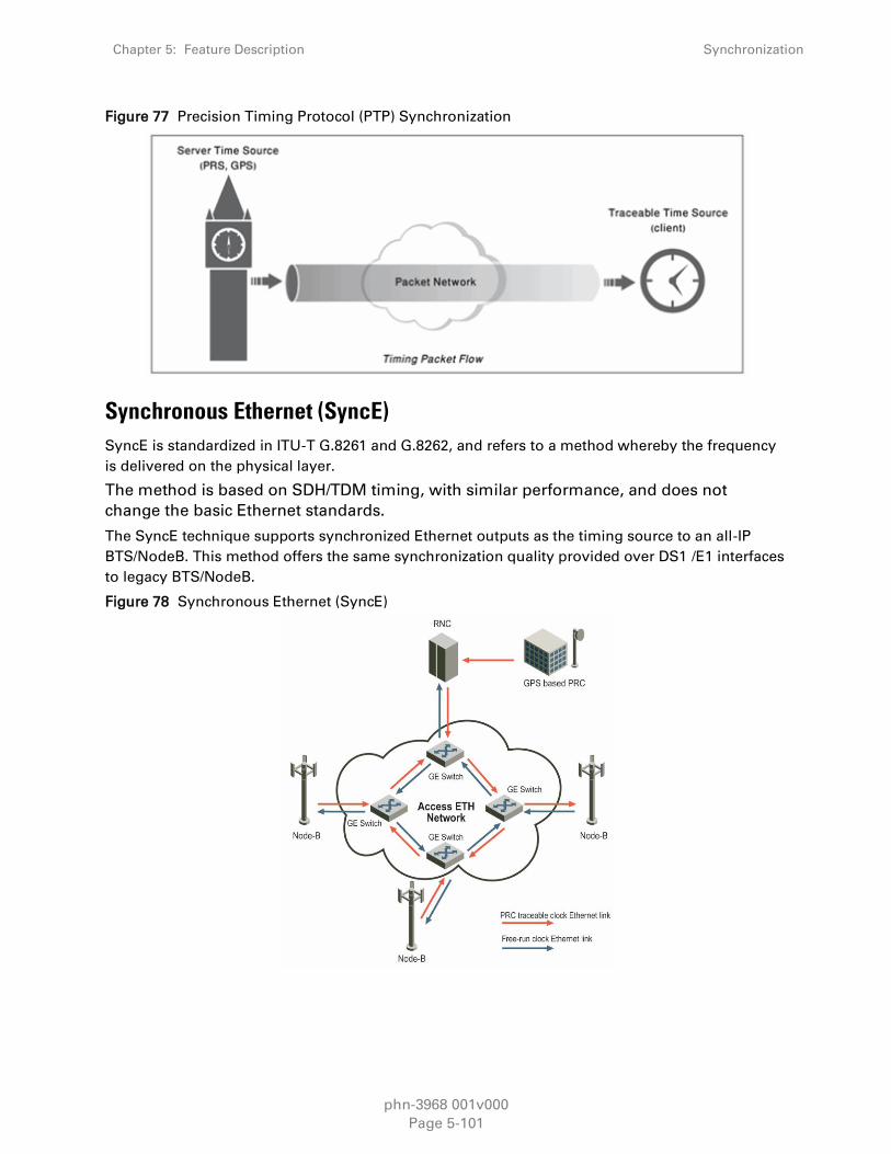
Chapter 5: Feature Description Synchronization
phn-3968 001v000
Page 5-101
Figure 77 Precision Timing Protocol (PTP) Synchronization
Synchronous Ethernet (SyncE)
SyncE is standardized in ITU-T G.8261 and G.8262, and refers to a method whereby the frequency
is delivered on the physical layer.
The method is based on SDH/TDM timing, with similar performance, and does not
change the basic Ethernet standards.
The SyncE technique supports synchronized Ethernet outputs as the timing source to an all-IP
BTS/NodeB. This method offers the same synchronization quality provided over DS1 /E1 interfaces
to legacy BTS/NodeB.
Figure 78 Synchronous Ethernet (SyncE)
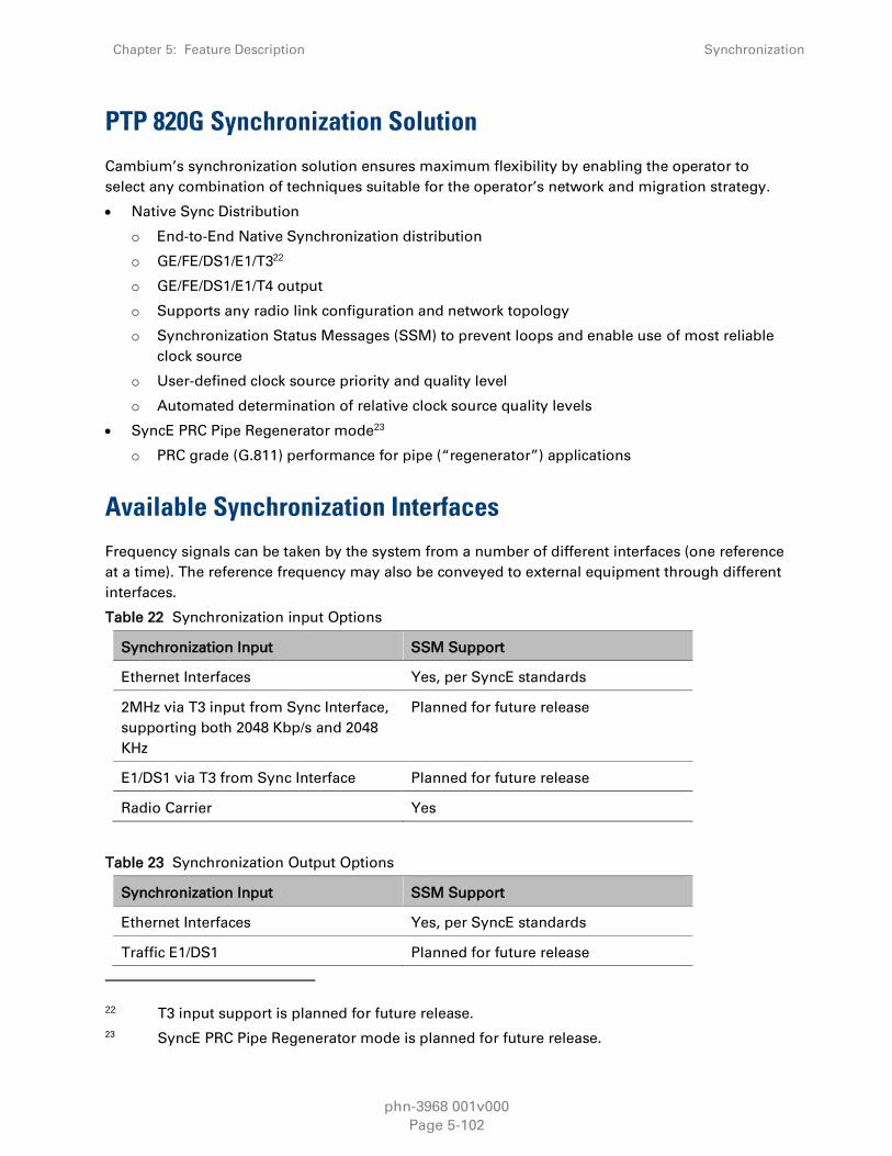
Chapter 5: Feature Description Synchronization
phn-3968 001v000
Page 5-102
PTP 820G Synchronization Solution
Cambium’s synchronization solution ensures maximum flexibility by enabling the operator to
select any combination of techniques suitable for the operator’s network and migration strategy.
Native Sync Distribution
o End-to-End Native Synchronization distribution
o GE/FE/DS1/E1/T322
o GE/FE/DS1/E1/T4 output
o Supports any radio link configuration and network topology
o Synchronization Status Messages (SSM) to prevent loops and enable use of most reliable
clock source
o User-defined clock source priority and quality level
o Automated determination of relative clock source quality levels
SyncE PRC Pipe Regenerator mode23
o PRC grade (G.811) performance for pipe (“regenerator”) applications
Available Synchronization Interfaces
Frequency signals can be taken by the system from a number of different interfaces (one reference
at a time). The reference frequency may also be conveyed to external equipment through different
interfaces.
Table 22 Synchronization input Options
Synchronization Input SSM Support
Ethernet Interfaces Yes, per SyncE standards
2MHz via T3 input from Sync Interface,
supporting both 2048 Kbp/s and 2048
KHz
Planned for future release
E1/DS1 via T3 from Sync Interface Planned for future release
Radio Carrier Yes
Table 23 Synchronization Output Options
Synchronization Input SSM Support
Ethernet Interfaces Yes, per SyncE standards
Traffic E1/DS1 Planned for future release
22 T3 input support is planned for future release.
23 SyncE PRC Pipe Regenerator mode is planned for future release.

Chapter 5: Feature Description Synchronization
phn-3968 001v000
Page 5-103
Synchronization Input SSM Support
2MHz via T4 output from Sync interface Planned for future release
E1/DS1 via T4 output from Sync
interface
Planned for future release
Radio Carrier Yes
Radio Channels Used for backwards compatibility with
FibeAir IP-10 units across a radio link.
Otherwise, it is not recommended.
When using a radio channel to distribute a frequency, 2Mbps of bandwidth is used for this
purpose.
It is possible to configure up to 16 synchronization sources in the system. At any given moment,
only one of these sources is active; the clock is taken from the active source onto all other
appropriately configured interfaces
Configuring Native Sync Distribution
Frequency is distributed by configuring the following parameters in each node:
System synchronization sources. These are the interfaces from which the frequency is taken
and distributed to other interfaces. Up to 16 sources can be configured in each node. A
revertive timer can be configured. For each interface, user must configure:
o Its clock quality level. The quality level may be fixed (according to ITU-T G.781 option II) or
automatic. When the quality level is automatic, it is determined by SSM messages.
o Its priority (1-16). No two interfaces may have the same priority.
For each interface, the source of its outgoing signal clock. This can be:
o Local clock: Causes the interface to generate its signal from a local oscillator, unrelated to
the system reference frequency.
o Synchronization reference: Causes the interface to generate its signal from the system
reference clock, which is taken from the synchronization source.
o Loop Timing: Causes the interface to generate the signal from its own input.
The node’s synchronization mode. This can be:
o Automatic: In this mode, the active source is automatically selected based on the interface
with highest available quality. Among interfaces with identical quality, the interface with
the highest priority is used.
o Force: The user can force the system to use a certain interface as the reference clock
source.24
24 Force mode is planned for future release.

Chapter 5: Feature Description Synchronization
phn-3968 001v000
Page 5-104
By configuring synchronization sources and transporting the reference frequency to the related
interfaces in a network, a frequency “flow” can be achieved, as shown in the example below,
where the reference frequency from a single node is distributed to a number of base stations.
Figure 79 Synchronization Configuration
The following restrictions apply for frequency distribution configuration:
An interface can either be used as a synchronization source or can take its signal from the
system reference, but not both (no loop timing available, except locally in SDH interfaces).
The clock taken from a line interface (DS1/E1, SDH, Ethernet) cannot be conveyed to another
line interface in the same card.
The clock taken from a radio channel cannot be conveyed to another radio channel in the same
radio.
If the signal driving the synchronization fails, an alarm will alert the user and the system will enter
holdover mode until another synchronization source signal is found.
Native Sync Distribution Mode
In this mode, synchronization is distributed natively end-to-end over the radio links in the network.
No TDM trails or DS1/E1 interfaces at the tail sites are required.
Synchronization is typically provided by one or more clock sources (SSU/GPS) at fiber hub sites.

Chapter 5: Feature Description Synchronization
phn-3968 001v000
Page 5-105
Figure 80 Native Sync Distribution Mode
In native Sync Distribution mode, the following interfaces can be used as the sync references:
E1 / DS125
GE (SyncE)
T3 (DS1 /E1 waveform)26
Additionally, the following interfaces can be used for sync output:
DS1/E1
GE/FE (SyncE)
T4 (2MHz or DS1 waveform)
Native Sync Distribution mode can be used in any link configuration and any network topology.
Ring topologies present special challenges for network synchronization. Any system that contains
more than one clock source for synchronization, or in which topology loops may exist, requires an
active mechanism to ensure that:
A single source is be used as the clock source throughout the network, preferably the source
with the highest accuracy.
There are no reference loops. In other words, no element in the network will use an input
frequency from an interface that ultimately derived that frequency from one of the outputs of
that network element.
PTP 820G’s Native Sync Distribution mechanism enables users to define a priority level for each
possible clock source. Synchronization Status Messages (SSM) are sent regularly through each
interface involved in frequency distribution, enabling the network to gather and maintain a
synchronization status for each interface according to the system’s best knowledge about the
frequency quality that can be conveyed by that interface.
25 Planned for future release.
26 Planned for future release.

Chapter 5: Feature Description Synchronization
phn-3968 001v000
Page 5-106
Based on these parameters, the network assigns each interface a quality level and determines
which interface to use as the current clock source. The network does this by evaluating the clock
quality of the available source interfaces and selecting, from those interfaces with the highest
quality, the interface with the highest user-defined priority.
The synchronization is re-evaluated whenever one of the following occurs:
Any synchronization source is added, edited, or deleted by a user.
The clock quality status changes for any source interface.
The synchronization reference is changed for the node.
Native Sync Distribution Examples
The figure below provides a Native Sync Distribution mode usage example in which
synchronization is provided to all-frame Node-Bs using SyncE. In this illustration, an PTP 820G at a
fiber node is synchronized to:
SyncE input from an Ethernet uplink
External synchronization input via a DS1/E1 interface
Figure 81 Native Sync Distribution Mode Usage Example
The following figure illustrates Native Sync Distribution in a tree scenario.

Chapter 5: Feature Description Synchronization
phn-3968 001v000
Page 5-107
Figure 82 Native Sync Distribution Mode – Tree Scenario
The following figure illustrates Native Sync Distribution in a ring scenario, during normal
operation.
Figure 83 Native Sync Distribution Mode – Ring Scenario (Normal Operation)
The following figure illustrates Native Sync Distribution in a ring scenario, where a link has failed
and the Native Sync timing distribution has been restored over an alternate path by using SSM
messages.

Chapter 5: Feature Description Synchronization
phn-3968 001v000
Page 5-108
Figure 84 Native Sync Distribution Mode – Ring Scenario (Link Failure)
SyncE PRC Pipe Regenerator Mode
Note
SyncE PRC Pipe Regenerator Mode is planned for future release.
In SyncE PRC pipe regenerator mode, frequency is transported between two GE interfaces through
the radio link.
PRC pipe regenerator mode makes use of the fact that the system is acting as a simple link (so no
distribution mechanism is necessary) in order to achieve the following:
Improved frequency distribution performance, with PRC quality.
Simplified configuration
In PRC pipe regenerator mode, frequency is taken from the incoming GE Ethernet or radio
interface signal, and used as a reference for the radio frame. On the receiver side, the radio frame
frequency is used as the reference signal for the outgoing Ethernet PHY.
Frequency distribution behaves in a different way for optical and electrical GE interfaces, because
of the way these interfaces are implemented:
For optical interfaces, separate and independent frequencies are transported in each direction.
For electrical interfaces, each PHY must act either as clock master or as clock slave in its own
link. For this reason, frequency can only be distributed in one direction, determined by the
user.

Chapter 5: Feature Description Synchronization
phn-3968 001v000
Page 5-109
SSM Support and Loop Prevention
In order to provide topological resiliency for synchronization transfer, PTP 820G implements the
passing of SSM messages over the radio interfaces. SSM timing in PTP 820G complies with ITU-T
G.781.
In addition, the SSM mechanism provides reference source resiliency, since a network may have
more than one source clock.
The following are the principles of operation:
At all times, each source interface has a “quality status” which is determined as follows:
o If quality is configured as fixed, then the quality status becomes “failure” upon interface
failure (such as LOS, LOC, LOF, etc.).
o If quality is automatic, then the quality is determined by the received SSMs or becomes
“failure” upon interface failure (such as LOS, LOC, LOF, etc.).
Each unit holds a parameter which indicates the quality of its reference clock. This is the
quality of the current synchronization source interface.
The reference source quality is transmitted through SSM messages to all relevant radio
interfaces.
Each unit determines the current active clock reference source interface:
o The interface with the highest available quality is selected.
o From among interfaces with identical quality, the interface with the highest priority is
selected.
In order to prevent loops, an SSM with quality “Do Not Use” is sent towards the active source
interface
At any given moment, the system enables users to display:
The current source interface quality.
The current received SSM status for every source interface.
The current node reference source quality.
As a reference, the following are the possible quality values (from highest to lowest):
AUTOMATIC (available only in interfaces for which SSM support is implemented)
G.811
SSU-A
SSU-B
G.813/8262 - default
DO NOT USE
Failure (cannot be configured by

Chapter 5: Feature Description TDM Services
phn-3968 001v000
Page 5-110
TDM Services
PTP 820G provides integrated support for transportation of TDM (DS1 / E1) services with
integrated DS1/ E1 interfaces (optional).
Two types of TDM services are supported using the same hardware:
Native TDM trails
TDM Pseudowire services (enabling interoperability with third party packet/PW equipment)
In addition, PTP 820G offers hybrid Ethernet and TDM services. Hybrid services can utilize either
Native TDM or pseudowire.
Figure 85 Hybrid Ethernet and TDM Services
Hybrid
Radio
Packet
Traffic
TDM
Traffic
TDM cross-connect (VCs)
Network processor (EVCs)
GE/FE
E1
TDM
PW
Services engine
Hybrid Ethernet and TDM services can also be transported via cascading interfaces. This enables
the creation of links among multiple PTP 820G units in a node for multi-carrier and multi-
directional applications.
Figure 86 Hybrid Ethernet and TDM Services Carried Over Cascading Interfaces
SAP
TDM cross-connect (VCs)-
Ethernet Services (EVCs)
SAPSNP
Hybrid
Radio Packet
Traffic
TDM
Traffic
SAPPort
Cascading Port
Port
Cascading Port
Ethernet Services (EVCs)
SAPSNPSAPSAPPort
User Port
(UNI)
GE/FE
Port
E1
SNP
TDM cross-connect (VCs)
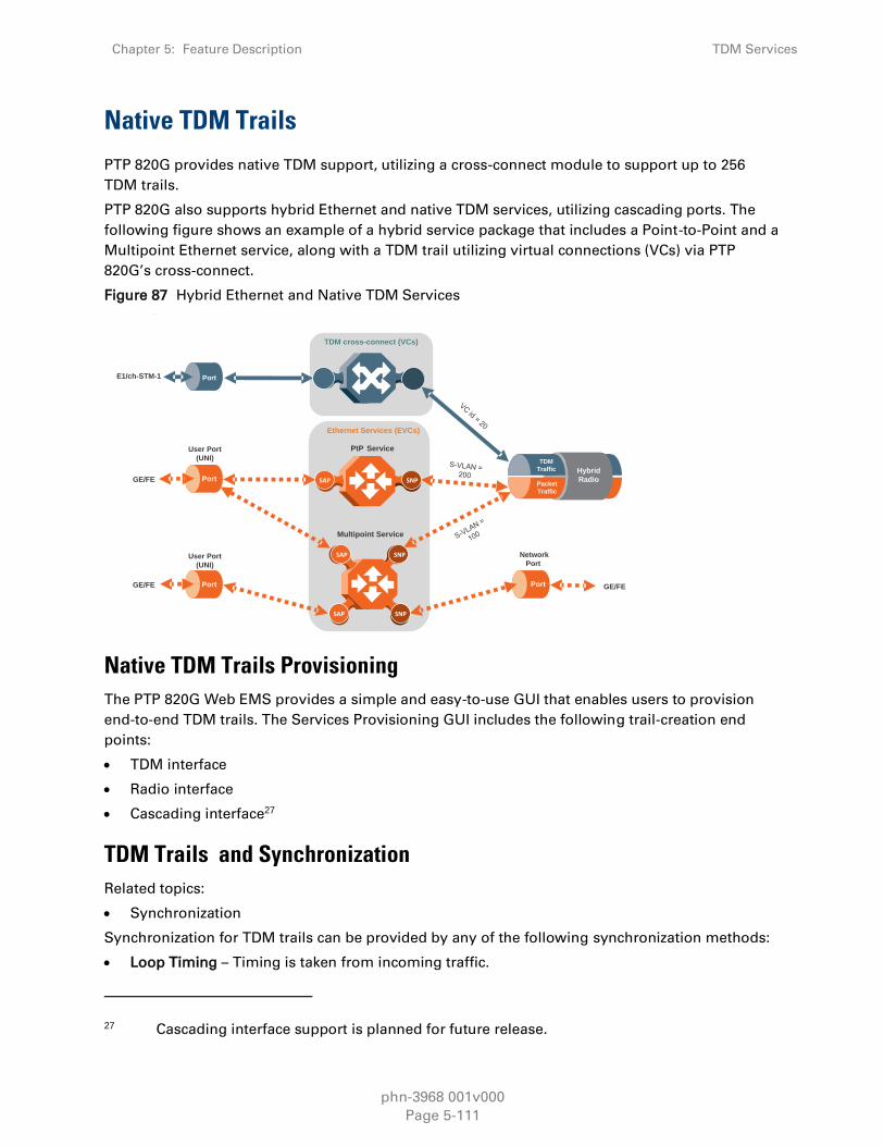
Chapter 5: Feature Description TDM Services
phn-3968 001v000
Page 5-111
Native TDM Trails
PTP 820G provides native TDM support, utilizing a cross-connect module to support up to 256
TDM trails.
PTP 820G also supports hybrid Ethernet and native TDM services, utilizing cascading ports. The
following figure shows an example of a hybrid service package that includes a Point-to-Point and a
Multipoint Ethernet service, along with a TDM trail utilizing virtual connections (VCs) via PTP
820G’s cross-connect.
Figure 87 Hybrid Ethernet and Native TDM Services
Ethernet Services (EVCs)
Hybrid
Radio Packet
Traffic
TDM
Traffic
PtP Service
SAP
SAPSNPSAPSAP
Multipoint Service
Port
Port
Port
User Port
(UNI)
GE/FE
GE/FE
E1/ch-STM-1
TDM cross-connect (VCs)
Port
Network
Port
GE/FE
SNP
SNP
SAP
SAPUser Port
(UNI)
Native TDM Trails Provisioning
The PTP 820G Web EMS provides a simple and easy-to-use GUI that enables users to provision
end-to-end TDM trails. The Services Provisioning GUI includes the following trail-creation end
points:
TDM interface
Radio interface
Cascading interface27
TDM Trails and Synchronization
Related topics:
Synchronization
Synchronization for TDM trails can be provided by any of the following synchronization methods:
Loop Timing – Timing is taken from incoming traffic.
27 Cascading interface support is planned for future release.

Chapter 5: Feature Description TDM Services
phn-3968 001v000
Page 5-112
Recovered Clock– Clock information is recovered on the egress path. Extra information may be
located in an RTP header that can be used to correct frequency offsets. Recovered Clock can
provide very accurate synchronization, but requires low PDV.
System Reference Clock –Trails are synchronized to the system reference clock.
TDM Trail Priority
In situations where ACM switches to lower modulations, reducing throughput, it is sometimes
necessary to drop some of the outgoing traffic. For native TDM trails, PTP 820G enables users to
define trails as high or low priority. This helps to ensure that high priority TDM traffic is not
interrupted due to fading or other temporary conditions affecting throughput.
TDM Path Protection
TDM path protection enables the operator to define two separate network paths for a single TDM
service. Two different kinds of path protection are available, each suitable for a different network
topology:
1:1 TDM path protection is suitable for ring networks that consist entirely of PTP 820G
elements with two end-point interfaces for the TDM service.
1+1 Dual Homing TDM path protection is suitable for networks in which the PTP 820G
elements are set up as a chain connected to the third party networks at two different sites. The
ring is closed on one side by the PTP 820G or any other equipment by third party supporting
standard SNCP. In this case, there are three end-point interfaces in the PTP 820G section of the
network.
Figure 88 1:1 TDM Path Protection – Ring Topology

Chapter 5: Feature Description TDM Services
phn-3968 001v000
Page 5-113
Figure 89 1+1 Dual Homing TDM Path Protection – Network Topology
1:1 TDM Path Protection
1:1 TDM path protection enables the operator to define two separate network paths for a single
TDM service. Each path has the same TDM interface end points, but traffic flows to the destination
via different paths. Bandwidth is utilized only on the active path, freeing up resources on the
standby path.
TDM path protection is implemented by means of configuring active and backup path at the TDM
service end-points.
1:1 TDM path protection can be configured to operate in revertive mode. In revertive mode, the
system monitors the availability of the protected path at all times. After switchover to the
protecting path, once the protected path is operational and available without any alarms, the
system waits the user-configured Wait to Restore (WTR) time and then, if the protected path
remains operational and available, initiates a revertive protection switch. A single WTR time is
configured for all the TDM trails in the system.
1+1 Dual Homing TDM Path Protection
1+1 TDM dual homing path protection is used for networks in which the PTP 820G and/or PTP 820
network elements are set up as a chain connected to third party networks at two different sites,
where one end-point is located on an PTP 820G or PTP 820 unit and the other end-point is located
on third-party equipment supporting standard SNCP.

Chapter 5: Feature Description TDM Services
phn-3968 001v000
Page 5-114
As with 1:1 TDM path protection, the operator defines two separate network paths for a single
TDM service. However, unlike 1:1 TDM path protection, traffic flows through both paths
simultaneously, thereby supporting interoperability with standard SNCP in the third party
equipment.
TDM Performance Monitoring
The following monitoring features are available for TDM services and interfaces: 28
PMs are computed at the TDM card and reported at 15-minute intervals, with one second
granularity.
PMs for the outgoing TDM trail:
o Errored seconds
o Severely errored seconds
o Unavailable seconds
PMs for incoming native DS1 / E1 signal:
o Errored seconds
o Severely errored seconds
o Unavailable seconds
PMs for incoming SDH 155MHz signal:
o Errored seconds
o Severely errored seconds
o Severely errored framing seconds
o Coding Violations
TDM Pseudowire
PTP 820G’s TDM Pseudowire provides TDM-over-packet capabilities by means of optional
integrated TDM interface that process TDM data, send the data through the system in frame
format that can be processed by the PTP 820G’s Ethernet ports, and convert the data back to TDM
format.
PTP 820G also supports all-packet Ethernet and TDM pseudowire services. The following figure
shows an example of an all-packet service package that includes two Point-to-Point services and
one Multipoint Ethernet service, where the first Point-to-Point service carries E1 pseudowire traffic.
This service package can be carried on any of the PTP 820G’s Ethernet ports.
28 Support for TDM PMs is planned for future release.

Chapter 5: Feature Description TDM Services
phn-3968 001v000
Page 5-115
Figure 90 All-Packet Ethernet and TDM Pseudowire Services
Packet
RadioPort
Port Port
Port
User Port
(UNI)
User Port
(UNI)
Network
Port
GE/FE
SAPSNPSAPSAP
SAPSNPSAPSAP
SNP
SNP
SAP
SAP
PtP Service
Multipoint
Service
S- VLAN =
200 Packet
TrafficGE/FE
GE/FE
E1
Ethernet Services (EVCs)
TDM
PWPtP Service
TDM Pseudowire Supported Standards
TDM Pseudowire supports the following standards:
SAToP – RFC 4553
CESoP – RFC 508629
TDM Pseudowire is compliant with the following encapsulations:
Ethernet VLAN (MEF-8)
IP/UDP (IETF)30
MPLS (MFA8 )31
Pseudowire Services
A Pseudowire service is a user-defined, bidirectional flow of information between a TDM signal
and a packed flow, which is always transported over Layer 2 Ethernet. Such a service interconnects
and makes use of the following elements:
TDM Signal
o The TDM signal may be an entire DS1 /E1 or a subset of DS0s (or DS1/E1 time-slots).32
PSN Tunnel
29 CESoP mode is planned for future release.
30 IP/UDP (IETF) encapsulation is planned for future release.
31 MPLS (MFA8) encapsulation is planned for future release.
32 A subset of DS0 is supported in CESoP, which is planned for a future release.

Chapter 5: Feature Description TDM Services
phn-3968 001v000
Page 5-116
o A PSN tunnel is the means by which the frames containing the TDM information are sent
and received through a PSN network. The type of tunnel to be used should match the
relevant transport network.
o Three types of PSN tunnels are supported: MEF-8 (Ethernet), UDP/IP, and MPLS (MFA8).
o For IP tunnels, the pseudowire services make use of the TDM card’s IP address, which is
user-configurable. For MEF-8 tunnels, the addressing is done through the TDM card’s MAC
address, which is fixed, but readable by users. MAC addresses are fixed per unit.
PSN Tunnel Group
o A PSN tunnel group is a grouping of two TDM tunnels, one of which will carry the
pseudowire service frames at any given time.
o A PSN tunnel group is used when path protection is required for a pseudowire service.
o One of the tunnels is designated as “primary.” The primary tunnel carries the pseudowire
frames in the absence of any failures. The other tunnel is designated as “secondary.” The
secondary tunnel is used whenever the primary path fails.
Pseudowire Profile
o A profile is a set of parameters that determine various operational settings of a PW service.
A single profile can be used for any number of services.
o The following is a short explanation of the main parameters:
Payload size – In terms of DS1/E1 frames per frame.
Jitter buffer – In milliseconds.
LOPS detection thresholds.
RTP timestamp usage details (for adaptive clock recovery).
Payload suppression and transmission patterns in case of errors.
In addition, there are a number of parameters at the PW Card level that must be configured
properly to ensure proper operation:
Ethernet traffic port settings
o Speed
o Duplex
o Auto-negotiation
o Flow control
TDM card IP address and subnet mask
Clock distribution
TDM Pseudowire and Synchronization
Related topics:
Synchronization
A key requirement of pseudowire technology is managing the synchronization of TDM signals. PTP
820G’s TDM Pseudowire supports the following synchronization methods:
Absolute Reference Clock (Common Clock) – All DS1/E1 lines are synchronized to the system
reference clock.

Chapter 5: Feature Description TDM Services
phn-3968 001v000
Page 5-117
Adaptive Clock Recovery – Clock information is included in the frames that contain the TDM
data. Extra information may be located in an RTP header that can be used to correct frequency
offsets. The clock information is extracted at the point where the frames are received and
reconverted to TDM. The extracted clock information is used for the reconversion to TDM.
Adaptive Clock Recovery can provide very accurate synchronization, but requires low PDV.
Differential Clock Recovery – A single common clock is given, while each DS1 line has its
independent clock referenced to this common clock. 33
Loop Timing – The pseudowire output signal uses the clock of the incoming DS1 lines Timing
will be independent for each DS1/E1 line.
1:1 TDM Pseudowire and Path Protection
For TDM pseudowire traffic redundancy, PTP 820G offers 1:1 TDM path protection, which protects
the traffic along the path.
Note
Alternatively, protection for the traffic along the path can be achieved using 1+1HSB
protection for the radios.
1:1 TDM path protection enables the operator to define two separate network paths for a single
TDM service. Each path has the same TDM interfaces end points, but traffic flows to the
destination via different paths.
For TDM Pseudowire services, 1:1 TDM Path protection requires the use of SOAM (CFM) at both
end-point interfaces. The TDM module sends two data streams to the CPU. Only the data stream
for the active path contains actual traffic. Both data streams contain continuity messages (CCMs).
This enables the TDM module to monitor the status of both paths without doubling the amount of
data being sent over the network. The TDM module determines when a switchover is necessary
based on the monitored network status.
In order to achieve TDM Pseudowire path protection, different provisioning should be made for the
Ethernet service corresponding to each of the two data streams. In order to do this, it is
recommended to map the corresponding Ethernet services to MSTP instance number 63, which is
meant for Traffic Engineering (ports are always forwarding) and to map the two different transport
VLANs over two different paths.
1:1 TDM pseudowire path protection uses CFM (G.8031) to monitor the network paths. Because
SOAM (CFM) is configured on the TDM module level, the TDM module can determine the status of
the entire network path, up to and including the card’s TDM interface.
33 Differential Clock Recovery is planned for future release.

Chapter 5: Feature Description TDM Services
phn-3968 001v000
Page 5-118
1:1 TDM path protection can be configured to operate in revertive mode. In revertive mode, the
system monitors the availability of the protected path at all times. After switchover to the
protecting path, once the protected path is operational and available without any alarms, the
system waits the user-configured Wait to Restore (WTR) time and then, if the protected path
remains operational and available, initiates a revertive protection switch. A single WTR time is
configured for all the TDM trails in the system.
TDM Pseudowire Performance Monitoring
The following monitoring features are available for TDM Pseudowire services and interfaces:
TDM PMs
Standard PM measurements are provided for each configured service:
Number of frames transmitted
Number of frames received
Number of lost frames detected
Number of frames received out-of-sequence but successfully reordered
Number of transitions from normal state to LOPS (loss of frame state)
Number of malformed frames received
Number of frames dropped because the receive buffer exceeded the maximum allowed depth
(jitter overruns)
Maximum deviation from the middle of the jitter buffer (maximum jitter buffer deviation)
Minimum jitter buffer usage registered during the prior one second (current minimum jitter
buffer count)
Maximum jitter buffer usage registered during the prior one second (current maximum jitter
buffer count)
TDM Signal PMs34
PMs are computed at the TDM card and reported at 15-minute intervals, with one second
granularity.
PMs for the recovered DS1/E1:
o Errored seconds
o Severely errored seconds
o Unavailable seconds
PMs for the pseudowire Ethernet connection:
o Frame Error Ratio (FER) performance
RFC 5604 PMs:
o Lost frames
o Reordered frames
34 Support for TDM pseudowire signal PMs is planned for future release.

Chapter 5: Feature Description TDM Services
phn-3968 001v000
Page 5-119
o Buffer underruns
o Misordered frames dropped
o Malformed frames
PMs for incoming native DS1/E1 signal:
o Errored seconds
o Severely errored seconds
o Unavailable seconds
PMs for incoming SDH 155MHz signal:
o Errored seconds
o Severely errored seconds
o Severely errored framing seconds
o Coding Violations
phn-3968 001v000
Page 6-1
Chapter 6: PTP 820G Management
This chapter includes:
Management Overview
Automatic Network Topology Discovery with LLDP Protocol
Management Communication Channels and Protocols
Web-Based Element Management System (Web EMS)
Command Line Interface (CLI)
Configuration Management
Software Management
IPv6 Support
In-Band Management
Local Management
Alarms
External Alarms
NTP Support
UTC Support
System Security Features

Chapter 6: PTP 820G Management Management Overview
phn-3968 001v000
Page 6-2
Management Overview
The Cambium Networks management solution is built on several layers of management:
NEL – Network Element-level CLI
EMS – HTTP web-based EMS
NMS and SML –PolyView/NetMaster platform
Every PTP 820 network element includes an HTTP web-based element manager that enables the
operator to perform element configuration, performance monitoring, remote diagnostics, alarm
reports, and more.
In addition, Cambium Networks provides an SNMP v1/v2c/v3 northbound interface on the PTP
820G.
Cambium Networks offers the NetMaster network management system (NMS), which provides
centralized operation and maintenance capability for the complete range of network elements in
an PTP 820G system. PTP 820G and other Cambium Networks network elements can also be
managed via Cambium’s PolyView NMS. To facilitate automated network topology discovery via
NMS, PTP 820G supports the Link Layer Discovery Protocol (LLDP).
In addition, management, configuration, and maintenance tasks can be performed directly via the
PTP 820G Command Line Interface (CLI). The CLI can be used to perform configuration operations
for PTP 820G units, as well as to configure several PTP 820G units in a single batch command.
Figure 91 Integrated PTP 820G Management Tools
Chapter 6: PTP 820G Management Automatic Network Topology Discovery with LLDP
Protocol
phn-3968 001v000
Page 6-3
Automatic Network Topology Discovery with LLDP
Protocol
PTP 820G supports the Link Layer Discovery Protocol (LLDP), a vendor-neutral layer 2 protocol that
can be used by a station attached to a specific LAN segment to advertise its identity and
capabilities and to receive identity and capacity information from physically adjacent layer 2 peers.
PTP 820G’s LLDP implementation is based on the IEEE 802.1AB – 2009 standard.
LLDP provides automatic network connectivity discovery by means of a port identity information
exchange between each port and its peer. The port exchanges information with its peer and
advertises this information to the NMS managing the unit. This enables the NMS to quickly
identify changes to the network topology.
Enabling LLDP on PTP 820 units enables the NMS to:
Automatically detect the PTP 820 unit neighboring the managed PTP 820 unit, and determine
the connectivity state between the two units.
Automatically detect a third-party switch or router neighboring the managed PTP 820 unit, and
determine the connectivity state between the PTP 820 unit and the switch or router.

Chapter 6: PTP 820G Management IPv6 Support
phn-3968 001v000
Page 6-4
IPv6 Support
PTP 820G management communications can use both IPv4 and IPv6. The unit IP address for
management can be configured in either or both formats.
Additionally, other management communications can utilize either IPv4 or IPv6. This includes:
Software file downloads
Configuration file import and export
Trap forwarding
Unit information file export (used primarily for maintenance and troubleshooting)

Chapter 6: PTP 820G Management Management Communication Channels and Protocols
phn-3968 001v000
Page 6-5
Management Communication Channels and
Protocols
Related Topics:
Secure Communication Channels
Network Elements can be accessed locally via serial or Ethernet management interfaces, or
remotely through the standard Ethernet LAN. The application layer is indifferent to the access
channel used.
The NMS can be accessed through its GUI interface application, which may run locally or in a
separate platform; it also has an SNMP-based northbound interface to communicate with other
management systems.
Table 24 Dedicated Management Ports
Port number Protocol Frame
structure
Details
161 SNMP UDP Sends SNMP Requests to the
network elements
162
Configurable
SNMP (traps) UDP Sends SNMP traps forwarding
(optional)
25 SMTP (mail) TCP Sends NMS reports and triggers
by email (optional)
69 TFTP UDP Uploads/ downloads
configuration files (optional)
80 HTTP TCP Manages devices
443 HTTPS TCP Manages devices (optional)
From 21 port
to any remote
port (>1023)
FTP Control
Port
TCP Downloads software and
configuration files. (FTP Server
responds to client's control port)
(optional)
From Any
port (>1023)
to any remote
port (>1023)
FTP Data Port TCP Downloads software and
configuration files.
The FTP server sends ACKs (and
data) to client's data port.
Optional
FTP server random port range
can be limited according to need
(i.e., according to the number of
parallel configuration uploads).

Chapter 6: PTP 820G Management Management Communication Channels and Protocols
phn-3968 001v000
Page 6-6
All remote system management is carried out through standard IP communications. Each NE
behaves as a host with a single IP address.
The communications protocol used depends on the management channel being accessed.
As a baseline, these are the protocols in use:
Standard HTTP for web-based management
Standard telnet for CLI-based management
The NMS uses a number of ports and protocols for different functions:
Table 25 NMS Server Receiving Data Ports
Port number Protocol Frame
structure
Details
162
Configurable
SNMP
(traps)
UDP Receive SNMP traps from network
elements
4001
Configurable
Propriety TCP CeraMap Server
69 TFTP UDP Downloads software and files
(optional)
21 FTP
Control
Port
TCP Downloads software and
configuration files. (FTP client initiates
a connection) (optional)
To any port
(>1023) from
any Port
(>1023)
FTP Data
Port
TCP Downloads software and
configuration files.(FTP Client initiates
data connection to random port
specified by server) (optional)
FTP Server random port range can be
limited according to needed
configuration (number of parallel
configuration uploads).
9205
Configurable
Propriety TCP User Actions Logger server (optional)
9207
Configurable
Propriety TCP CeraView Proxy (optional)
Table 26 Web Sending Data Ports
Port number Protocol Frame
structure
Details
80 HTTP TCP Manages device
443 HTTPS TCP Manages device (optional)

Chapter 6: PTP 820G Management Management Communication Channels and Protocols
phn-3968 001v000
Page 6-7
Table 27 Web Receiving Data Ports
Port number Protocol Frame
structure
Details
21 FTP TCP Downloads software files (optional)
Data port FTP TCP Downloads software files (optional)
Table 28 Additional Management Ports for PTP 820G
Port number Protocol Frame
structure
Details
23 telnet TCP Remote CLI access (optional)
22 SSH TCP Secure remote CLI access (optional)
Web-Based Element Management System (Web EMS)
The PTP 820G Element Management System (Web EMS) is an HTTP web-based element manager
that enables the operator to perform configuration operations and obtain statistical and
performance information related to the system, including:
Configuration Management – Enables you to view and define configuration data for the PTP
820G system.
Fault Monitoring – Enables you to view active alarms.
Performance Monitoring – Enables you to view and clear performance monitoring values and
counters.
Diagnostics and Maintenance – Enables you to define and perform loopback tests, software
updates, and IDU-RFU interface monitoring.
Security Configuration – Enables you to configure PTP 820G security features.
User Management – Enables you to define users and user profiles.
A Web-Based EMS connection to the PTP 820G can be opened using an HTTP Browser (Explorer or
Mozilla Firefox). The Web EMS uses a graphical interface. Most system configurations and
statuses are available via the Web EMS. However, some advanced configuration options are only
available via CLI.
The Web EMS shows the actual unit configuration and provides easy access to any interface in the
IDU.

Chapter 6: PTP 820G Management Command Line Interface (CLI)
phn-3968 001v000
Page 6-8
Command Line Interface (CLI)
A CLI connection to the PTP 820G can be opened via terminal (serial COM, speed: 115200, Data: 8
bits, Stop: 1 bit, Flow-Control: None), or via telnet. The Terminal format should be VT-100 with a
screen definition of 80 columns X 24 rows.
All parameter configurations can be performed via CLI.

Chapter 6: PTP 820G Management Configuration Management
phn-3968 001v000
Page 6-9
Configuration Management
The system configuration file consists of a set of all the configurable system parameters and their
current values.
PTP 820G configuration files can be imported and exported. This enables you to copy the system
configuration to multiple PTP 820G units.
System configuration files consist of a zip file that contains three components:
A binary configuration file which is used by the system to restore the configuration.
A text file which enables users to examine the system configuration in a readable format. The
file includes the value of all system parameters at the time of creation of the backup file.
An additional text file which enables users to write CLI scripts in order to make desired
changes in the backed-up configuration. This file is executed by the system after restoring the
configuration.35
The system provides three restore points to manage different configuration files. Each restore
point contains a single configuration file. Files can be added to restore points by creating backups
of the current system state or by importing them from an external server.
Note
In the Web EMS, these restore points are referred to as “file numbers.”
For example, a user may want to use one restore point to keep a last good configuration, another
to import changes from an external server, and the third to store the current configuration.
Any of the restore points can be used to apply a configuration file to the system.
The user can determine whether or not to include security-related settings, such as users and user
profiles, in the exported configuration file. By default, security settings are included.
Note
The option to enable or disable import and export of security parameters is planned
for future release.
35 The option to edit the backup configuration is planned for future release.

Chapter 6: PTP 820G Management Software Management
phn-3968 001v000
Page 6-10
Software Management
The PTP 820G software installation and upgrade process includes the following steps:
Download – The files required for the installation or upgrade are downloaded from a remote
server.
Installation – The files are installed in the appropriate modules and components of the PTP
820G.
Reset – The PTP 820G is restarted in order to boot the new software and firmware versions.
PTP 820G software and firmware releases are provided in a single bundle that includes software
and firmware for all components supported by the system, including RFUs. When the user
downloads a software bundle, the system verifies the validity of the bundle. The system also
compares the files in the bundle to the files currently installed in the PTP 820G and its
components, so that only files that differ between the new version bundle and the current version
in the system are actually downloaded. A message is displayed to the user for each file that is
actually downloaded.
Note
When downloading an older version, all files in the bundle may be downloaded,
including files that are already installed.
Software bundles can be downloaded via FTP, SFTP, HTTP, or HTTPS.
After the software download is complete, the user initiates the installation. A timer can be used to
perform the installation after a defined time interval. When an installation timer is used, the
system performs an automatic reset after the installation.36
Although RFU software is included in the standard installation bundle, the current software version
is not automatically updated when an installation is performed. To upgrade the software in an
RFU, you must perform the upgrade manually, per radio carrier. This enables users to manage IDU
and RFU software versions separately.
When the user restarts the PTP 820G after a software upgrade, only the components whose
software or firmware was actually upgraded are restarted.
Backup Software Version
Note
Backup software version support is planned for future release.
36 Installation timer is planned for future release.

Chapter 6: PTP 820G Management Software Management
phn-3968 001v000
Page 6-11
PTP 820G maintains a backup copy of the software bundle. In the event that the working software
version cannot be found, or the operating system fails to start properly, the system automatically
boots from the backup version, and the previously active version becomes the backup version.
Users can also update the backup version manually. The Web EMS includes a field that indicates
whether or not the active and backup software versions are identical.
In-Band Management
PTP 820G can optionally be managed In-Band, via its radio and Ethernet interfaces. This method of
management eliminates the need for a dedicated management interface. For more information,
see Management Service (MNG) on page 5-41.
Local Management
PTP 820G provides two FE interfaces for local management. The two management interfaces give
users the ability not only to manage the PTP 820G directly via a laptop or PC, but also to manage
other devices via the second management port of the PTP 820G.
For additional information:
Ethernet Management Interfaces
Chapter 6: PTP 820G Management Alarms
phn-3968 001v000
Page 6-12
Alarms
Configurable RSL Threshold Alarms and Traps
Users can configure alarm and trap generation in the event of RSL degradation beneath a user-
defined threshold. An alarm and trap are generated if the RSL remains below the defined threshold
for at least five seconds. The alarm is automatically cleared if the RSL subsequently remains above
the threshold for at least five seconds.
The RSL threshold is based on the nominal RSL value minus the RSL degradation margin. The
user defines both the nominal RSL value and the RSL degradation margin.
Alarms Editing
Users can change the description text (by appending extra text to the existing description) or the
severity of any alarm in the system. This feature is available through CLI only.
This is performed as follows:
Each alarm in the system is identified by a unique name (see separate list of system alarms
and events).
The user can perform the following operations on any alarm:
o View current description and severity
o Define the text to be appended to the description and/or severity
o Return the alarm to its default values
The user can also return all alarms and events to their default values.

Chapter 6: PTP 820G Management External Alarms
phn-3968 001v000
Page 6-13
External Alarms
PTP 820G includes a DB9 dry contact external alarms interface. The external alarms interface
supports five input alarms. For each alarm input, the user can configure the following:
1 Alarm administration (On or Off)
2 Alarm text
3 Alarm severity
Alarm severity can be configured to:
1 Indeterminate
2 Critical
3 Major
4 Minor
5 Warning

Chapter 6: PTP 820G Management NTP Support
phn-3968 001v000
Page 6-14
NTP Support
Related topics:
Synchronization
PTP 820G supports Network Time Protocol (NTP). NTP distributes Coordinated Universal Time
(UTC) throughout the system, using a jitter buffer to neutralize the effects of variable latency.
PTP 820G supports NTPv3 and NTPv4. NTPv4 provides interoperability with NTPv3 and with SNTP.

Chapter 6: PTP 820G Management UTC Support
phn-3968 001v000
Page 6-15
UTC Support
PTP 820G uses the Coordinated Universal Time (UTC) standard for time and date configuration.
UTC is a more updated and accurate method of date coordination than the earlier date standard,
Greenwich Mean Time (GMT).
Every PTP 820G unit holds the UTC offset and daylight savings time information for the location of
the unit. Each management unit presenting the information (CLI and Web EMS) uses its own UTC
offset to present the information in the correct time.

Chapter 6: PTP 820G Management System Security Features
phn-3968 001v000
Page 6-16
System Security Features
To guarantee proper performance and availability of a network as well as the data integrity of the
traffic, it is imperative to protect it from all potential threats, both internal (misuse by operators
and administrators) and external (attacks originating outside the network).
System security is based on making attacks difficult (in the sense that the effort required to carry
them out is not worth the possible gain) by putting technical and operational barriers in every
layer along the way, from the access outside the network, through the authentication process, up
to every data link in the network.
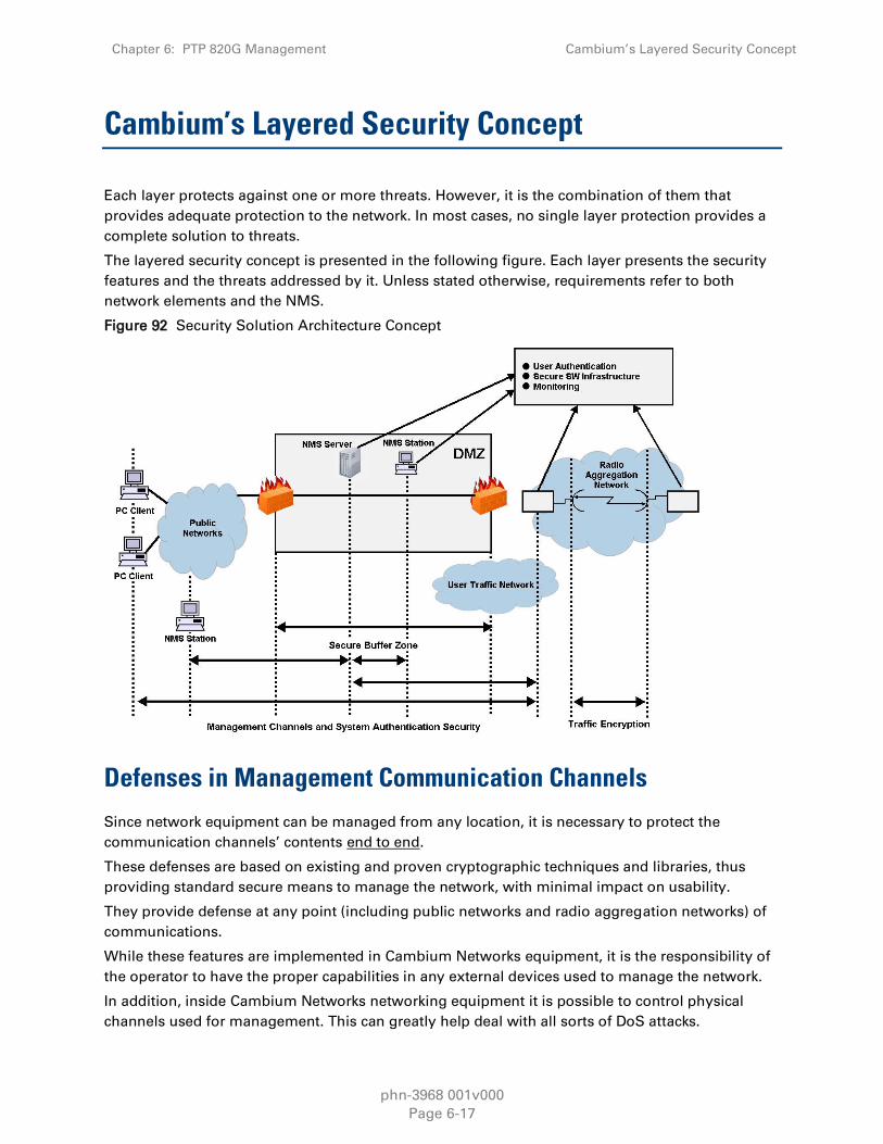
Chapter 6: PTP 820G Management Cambium’s Layered Security Concept
phn-3968 001v000
Page 6-17
Cambium’s Layered Security Concept
Each layer protects against one or more threats. However, it is the combination of them that
provides adequate protection to the network. In most cases, no single layer protection provides a
complete solution to threats.
The layered security concept is presented in the following figure. Each layer presents the security
features and the threats addressed by it. Unless stated otherwise, requirements refer to both
network elements and the NMS.
Figure 92 Security Solution Architecture Concept
Defenses in Management Communication Channels
Since network equipment can be managed from any location, it is necessary to protect the
communication channels’ contents end to end.
These defenses are based on existing and proven cryptographic techniques and libraries, thus
providing standard secure means to manage the network, with minimal impact on usability.
They provide defense at any point (including public networks and radio aggregation networks) of
communications.
While these features are implemented in Cambium Networks equipment, it is the responsibility of
the operator to have the proper capabilities in any external devices used to manage the network.
In addition, inside Cambium Networks networking equipment it is possible to control physical
channels used for management. This can greatly help deal with all sorts of DoS attacks.

Chapter 6: PTP 820G Management Cambium’s Layered Security Concept
phn-3968 001v000
Page 6-18
Operators can use secure channels instead or in addition to the existing management channels:
SNMPv3 for all SNMP-based protocols for both NEs and NMS
HTTPS for access to the NE’s web server
SSH-2 for all CLI access SFTP for all software and configuration download between NMS and
NEs
All protocols run with secure settings using strong encryption techniques. Unencrypted modes are
not allowed, and algorithms used must meet modern and client standards.
Users are allowed to disable all insecure channels.
In the network elements, the bandwidth of physical channels transporting management
communications is limited to the appropriate magnitude, in particular, channels carrying
management frames to the CPU.
Attack types addressed
Tempering with management flows
Management traffic analysis
Unauthorized software installation
Attacks on protocols (by providing secrecy and integrity to messages)
Traffic interfaces eavesdropping (by making it harder to change configuration)
DoS through flooding
Defenses in User and System Authentication Procedures
User Configuration and User Profiles
User configuration is based on the Role-Based Access Control (RBAC) model. According to the
RBAC model, permissions to perform certain operations are assigned to specific roles. Users are
assigned to particular roles, and through those role assignments acquire the permissions to
perform particular system functions.
In the PTP 820G GUI, these roles are called user profiles. Up to 50 user profiles can be configured.
Each profile contains a set of privilege levels per functionality group, and defines the management
protocols (access channels) that can be used to access the system by users to whom the user
profile is assigned.
The system parameters are divided into the following functional groups:
Security
Management
Radio
TDM
Ethernet
Synchronization
A user profile defines the permitted access level per functionality group. For each functionality
group, the access level is defined separately for read and write operations. The following access
levels can be assigned:

Chapter 6: PTP 820G Management Cambium’s Layered Security Concept
phn-3968 001v000
Page 6-19
None – No access to this functional group.
Normal – The user has access to parameters that require basic knowledge about the functional
group.
Advance – The user has access to parameters that require advanced knowledge about the
functional group, as well as parameters that have a significant impact on the system as a
whole, such as restoring the configuration to factory default settings.
User Identification
PTP 820G supports the following user identification features:
Configurable inactivity time-out for automatically closing unused management channels
Optional password strength enforcement. When password strength enforcement is enabled;
passwords must comply with the following rules:
o Password must be at least eight characters long.
o Password must include at least three of the following categories: lower-case characters,
upper-case characters, digits, and special characters.
o When calculating the number of character categories, upper-case letters used as the first
character and digits used as the last character of a password are not counted.
o The password cannot have been used within the user’s previous five passwords.
Users can be prompted to change passwords after a configurable amount of time (password
aging).
Users can be blocked for a configurable time period after a configurable number of
unsuccessful login attempts.
Users can be configured to expire at a certain date
Mandatory change of password at first time login can be enabled and disabled upon user
configuration. It is enabled by default.
Remote Authentication
Note
Remote authorization is planned for future release.
Certificate-based strong standard encryption techniques are used for remote authentication. Users
may choose to use this feature or not for all secure communication channels.
Since different operators may have different certificate-based authentication policies (for example,
issuing its own certificates vs. using an external CA or allowing the NMS system to be a CA), NEs
and NMS software provide the tools required for operators to enforce their policy and create
certificates according to their established processes.
Server authentication capabilities are provided.

Chapter 6: PTP 820G Management Cambium’s Layered Security Concept
phn-3968 001v000
Page 6-20
RADIUS Support
Note
Support for RADIUS is planned for future release.
The RADIUS protocol provides centralized user management services. PTP 820G supports RADIUS
server and provides a RADIUS client for authentication and authorization.
RADIUS can be enabled or disabled. When RADIUS is enabled, a user attempting to log into the
system from any access channel (CLI, WEB, NMS) is not authenticated locally. Instead, the user’s
credentials are sent to a centralized standard RADIUS server which indicates to the PTP 820G
whether the user is known, and which privilege is to be given to the user. RADIUS uses the same
user attributes and privileges defined for the user locally.
Note
When using RADIUS for user authentication and authorization, the access channel
limitations defined per user profile are not applicable. This means that when a user is
authorized via RADIUS, the user can access the unit via any available access channel.
RADIUS login works as follows:
If the RADIUS server is reachable, the system expects authorization to be received from the
server:
o The server sends the appropriate user privilege to the PTP 820G, or notifies the PTP 820G
that the user was rejected.
o If rejected, the user will be unable to log in. Otherwise, the user will log in with the
appropriate privilege and will continue to operate normally.
If the RADIUS server is unavailable, the PTP 820G will attempt to authenticate the user locally,
according to the existing list of defined users.
Note
Local login authentication is provided in order to enable users to manage the system
in the event that RADIUS server is unavailable. This requires previous definition of
users in the system. If the user is only defined in the RADIUS server, the user will be
unable to login locally in case the RADIUS server is unavailable.
In order to support PTP 820G - specific privilege levels, the vendor-specific field is used.
The following RADIUS servers are supported:
FreeRADIUS
RADIUS on Windows Server (IAS)
o Windows Server 2008
o Windows Server 2003
Cisco ACS

Chapter 6: PTP 820G Management Cambium’s Layered Security Concept
phn-3968 001v000
Page 6-21
Secure Communication Channels
PTP 820G supports a variety of standard encryption protocols and algorithms, as described in the
following sections.
SSH (Secured Shell)
Note
SSH support is planned for future release.
SSH protocol can be used as a secured alternative to Telnet. In PTP 820G:
SSHv2 is supported.
SSH protocol will always be operational. Admin users can choose whether to disable Telnet
protocol, which is enabled by default. Server authentication is based on PTP 820G’s public key.
RSA and DSA key types are supported.
Supported Encryptions: aes128-cbc, 3des-cbc, blowfish-cbc, cast128-cbc, arcfour128,
arcfour256, arcfour, aes192-cbc, aes256-cbc, aes128-ctr, aes192-ctr, aes256-ctr.
MAC (Message Authentication Code): SHA-1-96 (MAC length = 96 bits, key length = 160 bit).
Supported MAC: hmac-md5, hmac-sha1, hmac-ripemd160, hmac-sha1-96, hmac-md5-96'
The server authenticates the user based on user name and password. The number of failed
authentication attempts is not limited.
The server timeout for authentication is 10 minutes. This value cannot be changed.
HTTPS (Hypertext Transfer Protocol Secure)
Note
HTTPS support is planned for future release.
HTTPS combines the Hypertext Transfer protocol with the SSL/TLS protocol to provide encrypted
communication and secure identification of a network web server. PTP 820G enables
administrators to configure secure access via HTTPS protocol.
SFTP (Secure FTP)
SFTP can be used for the following operations:
Configuration upload and download,
Uploading unit information
Uploading a public key
Downloading certificate files
Downloading software

Chapter 6: PTP 820G Management Cambium’s Layered Security Concept
phn-3968 001v000
Page 6-22
Creation of Certificate Signing Request (CSR) File
Note
CSR support is planned for future release.
In order to create a digital certificate for the NE, a Certificate Signing Request (CSR) file should be
created by the NE. The CSR contains information that will be included in the NE's certificate such
as the organization name, common name (domain name), locality, and country. It also contains the
public key that will be included in the certificate. Certificate authority (CA) will use the CSR to
create the desired certificate for the NE.
While creating the CSR file, the user will be asked to input the following parameters that should be
known to the operator who applies the command:
Common name – The identify name of the element in the network (e.g., the IP address). The
common name can be a network IP or the FQDN of the element.
Organization – The legal name of the organization.
Organizational Unit - The division of the organization handling the certificate.
City/Locality - The city where the organization is located.
State/County/Region - The state/region where the organization is located.
Country - The two-letter ISO code for the country where the organization is location.
Email address - An email address used to contact the organization.
SNMP
PTP 820G supports SNMP v1, V2c, and v3. The default community string in NMS and the SNMP
agent in the embedded SW are disabled. Users are allowed to set community strings for access to
IDUs.
PTP 820G supports the following MIBs:
RFC-1213 (MIB II)
RMON MIB
Cambium Networks (proprietary) MIB.
Access to all IDUs in a node is provided by making use of the community and context fields in
SNMPv1 and SNMPv2c/SNMPv3, respectively.
For additional information:
PTP 820G MIB Reference

Chapter 6: PTP 820G Management Cambium’s Layered Security Concept
phn-3968 001v000
Page 6-23
Server Authentication (SSL / SLLv3)
Note
SSL and SLLv3 support is planned for future release.
All protocols making use of SSL (such as HTTPS) use SLLv3 and support X.509 certificates-
based server authentication.
Users with type of “administrator” or above can perform the following server (IDU)
authentication operations for certificates handling:
o Generate server key pairs (private + public)
o Export public key (as a file to a user-specified address)
o Install third-party certificates
o The Admin user is responsible for obtaining a valid certificate.
o Load a server RSA key pair that was generated externally for use by protocols making use
of SSL.
Non-SSL protocols using asymmetric encryption, such as SSH and SFTP, can make use of
public-key based authentication.
o Users can load trusted public keys for this purpose.
SSH
The CLI interface supports SSH-2
o Users of type of “administrator” or above can enable or disable SSH.
Security Log
The security log is an internal system file which records all changes performed to any security
feature, as well as all security related events.
Note
In order to read the security log, the user must upload the log to his or her server.
The security log file has the following attributes:
The file is of a “cyclic” nature (fixed size, newest events overwrite oldest).
The log can only be read by users with "admin" or above privilege.
The contents of the log file are cryptographically protected and digitally signed.
In the event of an attempt to modify the file, an alarm will be raised.
Users may not overwrite, delete, or modify the log file.
The security log records:
Changes in security configuration
o Carrying out “security configuration copy to mate”

Chapter 6: PTP 820G Management Cambium’s Layered Security Concept
phn-3968 001v000
Page 6-24
o Management channels time-out
o Password aging time
o Number of unsuccessful login attempts for user suspension
o Warning banner change
o Adding/deleting of users
o Password changed
o SNMP enable/disable
o SNMP version used (v1/v3) change
o SNMPv3 parameters change
Security mode
Authentication algorithm
User
Password
o SNMPv1 parameters change
Read community
Write community
Trap community for any manager
o HTTP/HTTPS change
o FTP/SFTP change
o Telnet and web interface enable/disable
o FTP enable/disable
o Loading certificates
o RADIUS server
o Radius enable/disable
o Remote logging enable/disable (for security and configuration logs)
o Syslog server address change (for security and configuration logs)
o System clock change
o NTP enable/disable
Security events
Successful and unsuccessful login attempts
N consecutive unsuccessful login attempts (blocking)
Configuration change failure due to insufficient permissions
SNMPv3/PV authentication failures
User logout
User account expired
For each recorded event the following information is available:
User ID
Communication channel (WEB, terminal, telnet/SSH, SNMP, NMS, etc.)

Chapter 6: PTP 820G Management Cambium’s Layered Security Concept
phn-3968 001v000
Page 6-25
IP address, if applicable
Date and time

phn-3968 001v000
Page 7-1
Chapter 7: Standards and Certifications
This chapter includes:
Supported Ethernet Standards
Supported TDM Pseudowire Encapsulations
Standards Compliance
Network Management, Diagnostics, Status, and Alarms
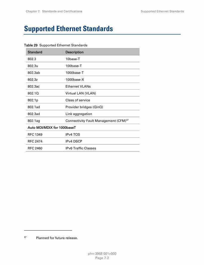
Chapter 7: Standards and Certifications Supported Ethernet Standards
phn-3968 001v000
Page 7-2
Supported Ethernet Standards
Table 29 Supported Ethernet Standards
Standard Description
802.3 10base-T
802.3u 100base-T
802.3ab 1000base-T
802.3z 1000base-X
802.3ac Ethernet VLANs
802.1Q Virtual LAN (VLAN)
802.1p Class of service
802.1ad Provider bridges (QinQ)
802.3ad Link aggregation
802.1ag Connectivity Fault Management (CFM)37
Auto MDI/MDIX for 1000baseT
RFC 1349 IPv4 TOS
RFC 2474 IPv4 DSCP
RFC 2460 IPv6 Traffic Classes
37 Planned for future release.

Chapter 7: Standards and Certifications Supported TDM Pseudowire Encapsulations
phn-3968 001v000
Page 7-3
Supported TDM Pseudowire Encapsulations
Table 30 Supported TDM Pseudowire Encapsulations
Certification Description Availability
VLAN (MEF-8) Circuit Emulation
Services over native
Ethernet frames
Available.
IP/UDP (IETF) Layer 3 encapsulation
over Ethernet
Planned for future
release.
MPLS (MFA8) MPLS encapsulation
over Ethernet
Planned for future
release.

Chapter 7: Standards and Certifications Standards Compliance
phn-3968 001v000
Page 7-4
Standards Compliance
Table 31 Standards Compliancc
Specification Standard
EMC EN 301 489-4
Safety IEC 60950-1
Ingress Protection IEC 60529 IP56
Operation – IDU Operating: ETSI EN 300 019-1-3 Class 3.2
Operation – RFU Operating: ETSI EN 300 019-1-4 Class 4.1
Storage Classification: ETSI EN 300 019-1-1 Class 1.2
Specification: ETSI EN 300 019-2-1 Specification T 1.2
Transportation Classification: ETSI EN 300 019-1-2 Class 2.3
Specification: ETSI EN 300 019-2-2 Specification T 2.3

Chapter 7: Standards and Certifications Network Management, Diagnostics, Status, and
Alarms
phn-3968 001v000
Page 7-5
Network Management, Diagnostics, Status, and
Alarms
Table 32 Network management, Diagnostics, Status and alarms
Network
Management System NetMaster NMS38 / PolyView
NMS Interface
protocol
SNMPv1/v2c/v3
XML over HTTP/HTTPS toward the NMS
Element
Management Web based EMS, CLI
Management
Channels & Protocols
HTTP/HTTPS39
Telnet/SSH-240
FTP/SFTP41
Authentication,
Authorization &
Accounting
User access control
X-509 Certificate
Management
Interface
Dedicated Ethernet interfaces or in-band in traffic
ports
In-Band Management Support dedicated VLAN for management
TMN The NMS functions are in accordance with ITU-T
recommendations for TMN
RSL Indication Power reading (dBm) available at RFU42, and NMS
Performance
Monitoring Integral with onboard memory per ITU-T G.826/G.828
38 PolyView NMS is also supported.
39 HTTPS support is planned for future release.
40 SSH support is planned for future release.
41 SFTP support is planned for future release.
42 Note that the voltage measured at the BNC port is not accurate and should be used only as
an aid.

Specifcations
phn-3968 001v000
Page 8-1
Chapter 8: Specifcations
This chapter includes:
Radio Specifications
o General Specifications
o Capacity Specifications
o Transmit Power Specifications (dBm)
o Receiver Threshold (RSL) Specifications
(dBm @ BER = 10-6)
o Frequency Bands
Network Specifications
o Ethernet Latency Specifications
o Ethernet Specifications
o Synchronization Specifications
Power Specifications
o Power Input Specifications
o Power Consumption Specifications
Physical and Electrical Specifications
o Mediation Device Losses
o TDM Specifications
o Supported Antenna Types
o Error! Reference source not found.
o Mechanical Specifications
o Environmental Specifications
Related Topics:
Standards and Certifications
Note
All specifications are subject to change without prior notification.

Chapter 8: Specifcations Radio Specifications
phn-3968 001v000
Page 8-2
Radio Specifications
General Specifications
Note
The specifications in this section refer to a PTP 820G system using an RFU-C
General Radio Specification for ANSI
Table 33 General Radio Specifications for ANSI
Frequency
(GHz)
Operating Frequency
Range (GHz)
Tx/Rx Spacing (MHz)
6L,6H 5.85-6.45, 6.4-7.1 252.04, 240, 266, 300, 340, 160, 170, 500
7,8 7.1-7.9, 7.7-8.5 154, 119, 161, 168, 182, 196, 208, 245, 250, 266,
300,310, 311.312, 500, 530
10 10.0-10.7 91, 168,350, 550
11 10.7-11.7 490, 520, 530
13 12.75-13.3 266
15 14.4-15.35 315, 420, 475, 644, 490, 728
18 17.7-19.7 1010, 1120, 1008, 1560
23 21.2-23.65 1008, 1200, 1232
26 24.2-26.5 800, 1008
28 27.35-29.5 350, 450, 490, 1008
32 31.8-33.4 812
36 36.0-37.0 700
38 37-40 1000, 1260, 700
Standards ANSI
Frequency Stability +0.001%
Frequency Source Synthesizer
RF Channel Selection Via EMS/NMS
Tx Range (Manual/ATPC) Up to 20dB dynamic range

Chapter 8: Specifcations Radio Specifications
phn-3968 001v000
Page 8-3
General Radio Specification for ETSI
Table 34 General Radio Specifications for ETSI
Frequency
(GHz)
Operating Frequency
Range (GHz)
Tx/Rx Spacing (MHz)
6L,6H 5.85-6.45, 6.4-7.1 252.04, 240, 266, 300, 340, 160, 170, 500
7,8 7.1-7.9, 7.7-8.5 154, 119, 161, 168, 182, 196, 208, 245, 250, 266,
300,310, 311.312, 500, 530
10 10.0-10.7 91, 168,350, 550
11 10.7-11.7 490, 520, 530
13 12.75-13.3 266
15 14.4-15.35 315, 420, 475, 644, 490, 728
18 17.7-19.7 1010, 1120, 1008, 1560
23 21.2-23.65 1008, 1200, 1232
26 24.2-26.5 800, 1008
28 27.35-29.5 350, 450, 490, 1008
32 31.8-33.4 812
36 36.0-37.0 700
38 37-40 1000, 1260, 700
Standards ETSI
Frequency Stability +0.001%
Frequency Source Synthesizer
RF Channel Selection Via EMS/NMS
Tx Range (Manual/ATPC) Up to 20dB dynamic range

Chapter 8: Specifcations Radio Specifications
phn-3968 001v000
Page 8-4
Capacity Specifications
Each table in this section includes ranges of capacity specifications according to frame size, with
ranges given for no Header De-Duplication, Layer-2 Header De-Duplication, and LTE-optimized
Header De-Duplication.43
Note
Ethernet capacity depends on average frame size.
For LTE-Optimized Header De-Duplication, the capacity figures are for LTE packets encapsulated
inside GTP tunnels with IPv4/UDP encapsulation and double VLAN tagging (QinQ). Capacity for
IPv6 encapsulation is higher. A Capacity Calculator tool is available for different encapsulations
and flow types.
These figures are valid for RFU-Ce. RFU-C units support modulations of up to 256 QAM and higher.
For exact capacity specifications for modulations beyond 256 QAM using standard RFU models,
contact your Cambium Networks representative.
7 MHz Channel Bandwidth (No XPIC)
Table 35 Capacity 7 MHz Channel Bandwidth (no XPIC)
Profile Modulation Minimum
required
capacity
license
Max # of
supported
DS1s /E1s
Ethernet throughput
No Header
De-
Duplication
L2 Header
De-
Duplication
LTE-Optimized
Header De-
Duplication
0 QPSK 10 4 8.37 8.44-9.55 8.79-26.91
1 8 PSK 50 5 12.52 12.62-14.29 13.15-40.24
2 16 QAM 50 8 17.92 18.06-20.45 18.82-57.59
3 32 QAM 50 10 23.98 24.17-27.36 25.19-77.07
4 64 QAM 50 12 29.67 29.9-33.85 31.16-95.34
5 128 QAM 50 15 35.6 35.88-40.61 37.39-114.4
6 256 QAM 50 17 40.99 41.31-46.76 43.05-131.72
7 512 QAM 50 18 43.95 44.29-50.14 46.15-141.23
8
1024 QAM
(Strong FEC) 50 19 47.1 47.47-53.73 49.46-151.36
9
1024 QAM
(Light FEC) 50 21 50.18 50.57-57.24 52.7-161.25
43 Header De-Duplication is planned for future release.

Chapter 8: Specifcations Radio Specifications
phn-3968 001v000
Page 8-5
14 MHz Channel Bandwidth (No XPIC)
Table 36 Capacity 14 MHz Channel Bandwidth (no XPIC)
Profile Modulation Minimum
required
capacity
license
Max # of
supported
DS1s /E1s
Ethernet throughput
No Header
De-
Duplication
L2 Header
De-
Duplication
LTE-Optimized
Header De-
Duplication
0 QPSK 50 8 19.18 19.33-21.89 20.15-61.65
1 8 PSK 50 12 28.97 29.2-33.05 30.43-93.1
2 16 QAM 50 16 39.74 40.05-45.33 41.73-127.7
3 32 QAM 50 22 52.58 52.99-59.99 55.22-168.97
4 64 QAM 50 26 64.65 65.16-73.76 67.9-207.77
5 128 QAM 100 32 78.09 78.69-89.09 82.01-250.94
6 256 QAM 100 36 89.19 89.88-101.75 93.67-286.61
7 512 QAM 100 40 98.46 99.23-112.33 103.41-316.41
8
1024 QAM
(Strong FEC) 150 42 104.22 105.04-118.9 109.46-334.93
9
1024 QAM
(Light FEC) 150 45 110.53 111.39-126.1 116.08-355.2
28 MHz Channel Bandwidth (No XPIC)
Table 37 Capacity 28 MHz Channel Bandwidth (no XPIC)
Profile Modulation Minimum
required
capacity
license
Max # of
supported
DS1s /E1s
Ethernet throughput
No Header
De-
Duplication
L2 Header
De-
Duplication
LTE-Optimized
Header De-
Duplication
0 QPSK 50 16 39.64 39.95-45.23 41.64-127.4
1 8 PSK 50 24 59.39 59.85-67.76 62.38-190.86
2 16 QAM 100 33 81.23 81.87-92.68 85.31-261.05
3 32 QAM 100 43 106.97 107.8-122.03 112.34-343.74
4 64 QAM 150 53 131.8
132.83-
150.37 138.42-423.55
5 128 QAM 150 64 158.53
159.76-
180.86 166.49-509.45

Chapter 8: Specifcations Radio Specifications
phn-3968 001v000
Page 8-6
Profile Modulation Minimum
required
capacity
license
Max # of
supported
DS1s /E1s
Ethernet throughput
No Header
De-
Duplication
L2 Header
De-
Duplication
LTE-Optimized
Header De-
Duplication
6 256 QAM
200 73 180.57
181.98-
206.01 189.64-580.28
7 512 QAM
200 80 199.22
200.77-
227.28 209.23-640.22
8
1024 QAM
(Strong FEC) 225 85 211.89
213.54-
241.74 222.53-680.92
9
1024 QAM
(Light FEC) 225 90 224.96
226.71-
256.64 236.26-722.91
10 2048 QAM 250 97 241.31 243.19-275.3 253.43-775.47
28 MHz Channel Bandwidth with XPIC
Table 38 Capacity 28 MHz Channel Bandwidth with XPIC
Profile Modulation Minimum
required
capacity
license
Max # of
supported
DS1s /E1s
Ethernet throughput
No Header
De-
Duplication
L2 Header
De-
Duplication
LTE-Optimized
Header De-
Duplication
0 QPSK 50 16 38.72 39.02-44.17 40.66-124.42
1 8 PSK 50 24 57.92 58.37-66.07 60.82-186.12
2 16 QAM 100 32 79.16 79.78-90.31 83.14-254.38
3 32 QAM 100 42 104.17
104.98-
118.85 109.41-334.77
4 64 QAM 150 52 128.38
129.38-
146.46 134.83-412.56
5 128 QAM 150 63 155.07
156.28-
176.91 162.86-498.33
6 256 QAM
200 72 177.47
178.85-
202.47 186.39-570.31
7 512 QAM
200 80 197.21
198.74-
224.99 207.12-633.74
8
1024 QAM
(Strong FEC) 225 85 209.66
211.29-
239.19 220.19-673.74

Chapter 8: Specifcations Radio Specifications
phn-3968 001v000
Page 8-7
Profile Modulation Minimum
required
capacity
license
Max # of
supported
DS1s /E1s
Ethernet throughput
No Header
De-
Duplication
L2 Header
De-
Duplication
LTE-Optimized
Header De-
Duplication
9
1024 QAM
(Light FEC) 225 90 222.59
224.32-
253.94 233.77-715.31
10 2048 QAM
250 97 241.3
243.18-
275.29 253.42-775.44
30 MHz Channel Bandwidth (No XPIC)
Table 39 Capacity 30 MHz Channel Bandwidth (no XPIC)
Profile Modulation Minimum
required
capacity
license
Max # of
supported
DS1s /E1s
Ethernet throughput
No Header
De-
Duplication
L2 Header
De-
Duplication
LTE-Optimized
Header De-
Duplication
0 QPSK 50 23 42.04 42.36-47.96 44.15-135.09
1 8 PSK 50 33 61.19 61.66-69.81 64.26-196.63
2 16 QAM 100 46 86.12 86.79-98.25 90.45-276.76
3 32 QAM 100 60 113.35
114.23-
129.32 119.04-364.26
4 64 QAM 150 74 139.58
140.67-
159.24 146.59-448.55
5 128 QAM 150 89 168.01
169.31-
191.67 176.44-539.9
6 256 QAM
200 103 193.14
194.64-
220.34 202.84-620.67
7 512 QAM
200 109 205.91
207.51-
234.91 216.25-661.69
8
1024 QAM
(Strong FEC) 225 119 224.56 226.3-256.19 235.84-721.63
9
1024 QAM
(Light FEC) 250 126 237.82
239.67-
271.32 249.77-764.26

Chapter 8: Specifcations Radio Specifications
phn-3968 001v000
Page 8-8
30 MHz Channel Bandwidth with XPIC
Table 40 Capacity 30 MHz Channel Bandwidth with XPIC
Profile Modulation Minimum
required
capacity
license
Max # of
supported
DS1s /E1s
Ethernet throughput
No Header
De-
Duplication
L2 Header
De-
Duplication
LTE-Optimized
Header De-
Duplication
0 QPSK 50 23 41.1 41.42-46.89 43.16-132.08
1 8 PSK 50 33 61.45 61.92-70.1 64.53-197.46
2 16 QAM 100 46 83.89 84.54-95.7 88.1-269.58
3 32 QAM 100 60 110.52
111.38-
126.08 116.07-355.15
4 64 QAM 150 74 136
137.06-
155.16 142.83-437.04
5 128 QAM 150 89 164.35 165.63-187.5 172.61-528.17
6 256 QAM
200 103 188.07
189.54-
214.56 197.52-604.38
7 512 QAM
200 109 209.04
210.66-
238.48 219.54-671.76
8
1024 QAM
(Strong FEC) 225 119 222.05
223.78-
253.33 233.21-713.58
9
1024 QAM
(Light FEC) 250 126 235.75
237.58-
268.95 247.59-757.59
40 MHz Channel Bandwidth with XPIC
Table 41 Capacity 40 MHz Channel Bandwidth with XPIC
Profile Modulation Minimum
required
capacity
license
Max # of
supported
DS1s /E1s
Ethernet throughput
No Header
De-
Duplication
L2 Header
De-
Duplication
LTE-Optimized
Header De-
Duplication
0 QPSK 50 31 55.3 55.73-63.09 58.08-177.72
1 8 PSK 100 45 82.53 83.17-94.16 86.68-265.22
2 16 QAM 100 62 112.42 113.3-128.26 118.07-361.28
3 32 QAM 150 81 148.14 149.29-169 155.58-476.05
4 64 QAM 200 99 181.95
183.36-
207.58 191.09-584.71

Chapter 8: Specifcations Radio Specifications
phn-3968 001v000
Page 8-9
Profile Modulation Minimum
required
capacity
license
Max # of
supported
DS1s /E1s
Ethernet throughput
No Header
De-
Duplication
L2 Header
De-
Duplication
LTE-Optimized
Header De-
Duplication
5 128 QAM 200 120 220.06
221.77-
251.05 231.11-707.17
6 256 QAM 250 129 236.95 238.8-270.33 248.86-761.47
7 512 QAM
300 141 273.16
275.28-
311.63 286.88-833.33
8
1024 QAM
(Strong FEC)
300 160
297.17
299.49-
339.03 312.1-833.33
9
1024 QAM
(Light FEC)
350 170
315.56 318.01-360 331.41-833.33
40 MHz Channel Bandwidth (No XPIC)
Table 42 Capacity 40 MHz Channel Bandwidth (no XPIC)
Profile Modulation Minimum
required
capacity
license
Max # of
supported
DS1s /E1s
Ethernet throughput
No Header
De-
Duplication
L2 Header
De-
Duplication
LTE-Optimized
Header De-
Duplication
0 QPSK 50 31 56.92 57.37-64.94 59.78-182.92
1 8 PSK 100 45 84.93 85.59-96.9 89.2-272.94
2 16 QAM 100 62 115.67
116.57-
131.96 121.48-371.72
3 32 QAM 150 81 152.42
153.61-
173.89 160.08-489.82
4 64 QAM 200 99 187.2
188.65-
213.56 196.6-601.57
5 128 QAM 200 120 226.44 228.2-258.34 237.82-727.69
6 256 QAM
250 129 243.43
245.32-
277.72 255.66-782.28
7 512 QAM
300 141 266.66
268.74-
304.22 280.06-833.33
8
1024 QAM
(Strong FEC) 300 160 302.41
304.76-
345.01 317.6-833.33
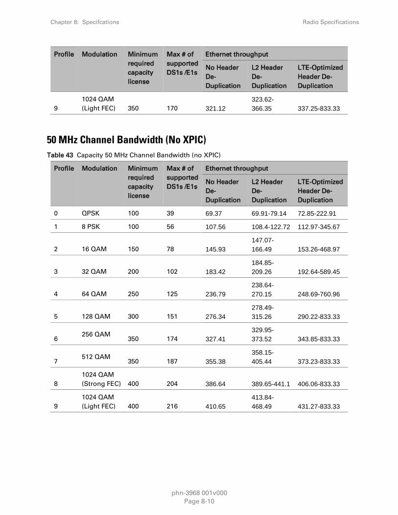
Chapter 8: Specifcations Radio Specifications
phn-3968 001v000
Page 8-10
Profile Modulation Minimum
required
capacity
license
Max # of
supported
DS1s /E1s
Ethernet throughput
No Header
De-
Duplication
L2 Header
De-
Duplication
LTE-Optimized
Header De-
Duplication
9
1024 QAM
(Light FEC) 350 170 321.12
323.62-
366.35 337.25-833.33
50 MHz Channel Bandwidth (No XPIC)
Table 43 Capacity 50 MHz Channel Bandwidth (no XPIC)
Profile Modulation Minimum
required
capacity
license
Max # of
supported
DS1s /E1s
Ethernet throughput
No Header
De-
Duplication
L2 Header
De-
Duplication
LTE-Optimized
Header De-
Duplication
0 QPSK 100 39 69.37 69.91-79.14 72.85-222.91
1 8 PSK 100 56 107.56 108.4-122.72 112.97-345.67
2 16 QAM 150 78 145.93
147.07-
166.49 153.26-468.97
3 32 QAM 200 102 183.42
184.85-
209.26 192.64-589.45
4 64 QAM 250 125 236.79
238.64-
270.15 248.69-760.96
5 128 QAM 300 151 276.34
278.49-
315.26 290.22-833.33
6 256 QAM
350 174 327.41
329.95-
373.52 343.85-833.33
7 512 QAM
350 187 355.38
358.15-
405.44 373.23-833.33
8
1024 QAM
(Strong FEC) 400 204 386.64 389.65-441.1 406.06-833.33
9
1024 QAM
(Light FEC) 400 216 410.65
413.84-
468.49 431.27-833.33

Chapter 8: Specifcations Radio Specifications
phn-3968 001v000
Page 8-11
56 MHz Channel Bandwidth (No XPIC)
Table 44 Capacity 56 MHz Channel Bandwidth (no XPIC)
Profile Modulation Minimum
required
capacity
license
Max # of
supported
DS1s /E1s
Ethernet throughput
No Header
De-
Duplication
L2 Header
De-
Duplication
LTE-Optimized
Header De-
Duplication
0 QPSK 100 33 81.43 82.07-92.9 85.52-261.69
1 8 PSK 150 49 121.33
122.27-
138.42 127.42-389.9
2 16 QAM 150 67 165.11 166.4-188.37 173.41-530.6
3 32 QAM 225 88 217.38
219.07-
247.99 228.29-698.55
4 64 QAM 300 107 266.84
268.92-
304.43 280.25-833.33
5 128 QAM 300 130 322.6
325.11-
368.04 338.8-833.33
6 256 QAM
400 148 368.98
371.85-
420.95 387.51-833.33
7 512 QAM
400 161 400.59
403.71-
457.02 420.72-833.33
8
1024 QAM
(Strong FEC) 450 175 435.7
439.09-
497.07 457.59-833.33
9
1024 QAM
(Light FEC) 500 185 462.43
466.03-
527.56 485.66-833.33
10 2048 QAM
500 201 501.53
505.43-
572.17 526.72-833.33
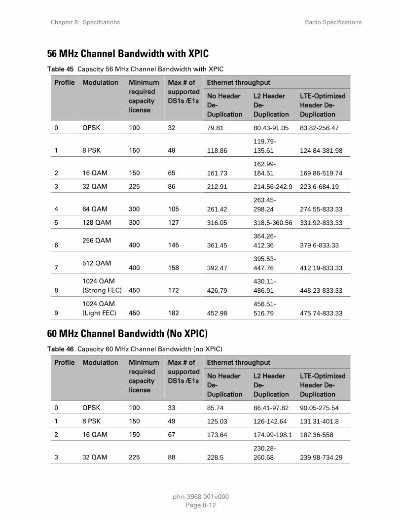
Chapter 8: Specifcations Radio Specifications
phn-3968 001v000
Page 8-12
56 MHz Channel Bandwidth with XPIC
Table 45 Capacity 56 MHz Channel Bandwidth with XPIC
Profile Modulation Minimum
required
capacity
license
Max # of
supported
DS1s /E1s
Ethernet throughput
No Header
De-
Duplication
L2 Header
De-
Duplication
LTE-Optimized
Header De-
Duplication
0 QPSK 100 32 79.81 80.43-91.05 83.82-256.47
1 8 PSK 150 48 118.86
119.79-
135.61 124.84-381.98
2 16 QAM 150 65 161.73
162.99-
184.51 169.86-519.74
3 32 QAM 225 86 212.91 214.56-242.9 223.6-684.19
4 64 QAM 300 105 261.42
263.45-
298.24 274.55-833.33
5 128 QAM 300 127 316.05 318.5-360.56 331.92-833.33
6 256 QAM
400 145 361.45
364.26-
412.36 379.6-833.33
7 512 QAM
400 158 392.47
395.53-
447.76 412.19-833.33
8
1024 QAM
(Strong FEC) 450 172 426.79
430.11-
486.91 448.23-833.33
9
1024 QAM
(Light FEC) 450 182 452.98
456.51-
516.79 475.74-833.33
60 MHz Channel Bandwidth (No XPIC)
Table 46 Capacity 60 MHz Channel Bandwidth (no XPIC)
Profile Modulation Minimum
required
capacity
license
Max # of
supported
DS1s /E1s
Ethernet throughput
No Header
De-
Duplication
L2 Header
De-
Duplication
LTE-Optimized
Header De-
Duplication
0 QPSK 100 33 85.74 86.41-97.82 90.05-275.54
1 8 PSK 150 49 125.03 126-142.64 131.31-401.8
2 16 QAM 150 67 173.64 174.99-198.1 182.36-558
3 32 QAM 225 88 228.5
230.28-
260.68 239.98-734.29

Chapter 8: Specifcations Radio Specifications
phn-3968 001v000
Page 8-13
Profile Modulation Minimum
required
capacity
license
Max # of
supported
DS1s /E1s
Ethernet throughput
No Header
De-
Duplication
L2 Header
De-
Duplication
LTE-Optimized
Header De-
Duplication
4 64 QAM 300 107 280.58 282.77-320.1 294.68-833.33
5 128 QAM 300 130 339.19
341.83-
386.96 356.23-833.33
6 256 QAM 400 148 391.37 394.42-446.5 411.03-833.33
7 512 QAM
400 161 420.95
424.23-
480.24 442.1-833.33
8
1024 QAM
(Strong FEC) 450 175 457.72
461.28-
522.19 480.71-833.33
9
1024 QAM
(Light FEC) 500 185 486.3
490.08-
554.79 510.73-833.33
10 2048 QAM
500 201 526.96
531.07-
601.19 553.44-833.33
Transmit Power Specifications (dBm)
Table 47 Transmit Power Specifications
Modulation 6-8 GHz 11-15 GHz 18-23 GHz 26 GHz 28 GHz 31 GHz 32,38 GHz
QPSK 26 24 22 21 14 16 18
8 PSK 26 24 22 21 14 16 18
16 QAM 25 23 21 20 14 15 17
32 QAM 24 22 20 19 14 14 16
64 QAM 24 22 20 19 14 14 16
128 QAM 24 22 20 19 14 14 16
256 QAM 22 20 18 17 12 12 14
512 QAM 22 20 18 17 9 12 14
1024 QAM 21 19 17 16 8 11 13
2048 QAM 19 17 15 14 6 9 11
Note
2048 QAM support is planned for future release.

Chapter 8: Specifcations Radio Specifications
phn-3968 001v000
Page 8-14
Receiver Threshold (RSL) Specifications
(dBm @ BER = 10-6)44
Table 48 Receiver Threshold for 7 MHz Channel spacing
Profile Modulation Frequency (GHz)
6 7-10 11-15 18 23 26 28 31-38
0 QPSK -95 -94.5 -95 -94 -93.5 -92.5 -90.5 -91.5
1 8 PSK -89 -88.5 -89 -88 -87.5 -86.5 -84.5 -85.5
2 16 QAM -88.5 -88 -88.5 -87.5 -87 -86.0 -84.0 -85.0
3 32 QAM -85 -84.5 -85 -84 -83.5 -82.5 -80.5 -81.5
4 64 QAM -82 -81.5 -82 -81 -80.5 -79.5 -77.5 -78.5
5 128 QAM -79 -78.5 -79 -78 -77.5 -76.5 -74.5 -75.5
6 256 QAM -75.5 -75 -75.5 -74.5 -74 -73.0 -71.0 -72.0
7 512 QAM -73.5 -73 -73.5 -72.5 -72 -71.0 -69.0 -70.0
8 1024 QAM
(strong FEC) -70 -69.5 -70 -69 -68.5 -67.5 -65.5 -66.5
9 1024 QAM
(light FEC) -69.5 -69 -69.5 -68.5 -68 -67.0 -65.0 -66.0
Table 49 Receiver Threshold for 14 MHz Channel spacing
Profile Modulation Frequency (GHz)
6 7-10 11-15 18 23 26 28 31-38
0 QPSK -92.0 -91.5 -92.0 -91.0 -90.5 -89.5 -87.5 -88.5
1 8 PSK -86.0 -85.5 -86.0 -85.0 -84.5 -83.5 -81.5 -82.5
2 16 QAM -85.0 -84.5 -85.0 -84.0 -83.5 -82.5 -80.5 -81.5
3 32 QAM -82.0 -81.5 -82.0 -81.0 -80.5 -79.5 -77.5 -78.5
4 64 QAM -79.0 -78.5 -79.0 -78.0 -77.5 -76.5 -74.5 -75.5
5 128 QAM -75.5 -75.0 -75.5 -74.5 -74.0 -73.0 -71.0 -72.0
6 256 QAM -73.0 -72.5 -73.0 -72.0 -71.5 -70.5 -68.5 -69.5
7 512 QAM -70.0 -69.5 -70.0 -69.0 -68.5 -67.5 -65.5 -66.5
44 Refer to RFU-C roll-out plan for availability of each frequency.

Chapter 8: Specifcations Radio Specifications
phn-3968 001v000
Page 8-15
Profile Modulation Frequency (GHz)
6 7-10 11-15 18 23 26 28 31-38
8 1024 QAM
(strong FEC) -67.0 -66.5 -67.0 -66.0 -65.5 -64.5 -62.5 -63.5
9 1024 QAM
(light FEC) -66.5 -66.0 -66.5 -65.5 -65.0 -64.0 -62.0 -63.0
Table 50 Receiver Threshold for 28 MHz Channel spacing
Profile Modulation Frequency (GHz)
6 7-10 11-15 18 23 26 28 31-38
0 QPSK -89.0 -88.5 -89.0 -88.0 -87.5 -86.5 -84.5 -85.5
1 8 PSK -84.5 -84.0 -84.5 -83.5 -83.0 -82.0 -80.0 -81.0
2 16 QAM -82.5 -82.0 -82.5 -81.5 -81.0 -80.0 -78.0 -79.0
3 32 QAM -79.0 -78.5 -79.0 -78.0 -77.5 -76.5 -74.5 -75.5
4 64 QAM -76.0 -75.5 -76.0 -75.0 -74.5 -73.5 -71.5 -72.5
5 128 QAM -72.5 -72.0 -72.5 -71.5 -71.0 -70.0 -68.0 -69.0
6 256 QAM -69.5 -69.0 -69.5 -68.5 -68.0 -67.0 -65.0 -66.0
7 512 QAM -67.5 -67.0 -67.5 -66.5 -66.0 -65.0 -63.0 -64.0
8 1024 QAM
(Strong FEC) -64.5 -64.0 -64.5 -63.5 -63.0 -62.0 -60.0 -61.0
9 1024 QAM
(Light FEC) -63.5 -63.0 -63.5 -62.5 -62.0 -61.0 -59.0 -60.0
10 2048 QAM -60 -59.5 -60 -59 -58.5 -57.5 -55.5 -56.5
Table 51 Receiver Threshold for 30MHz Channel spacing
Profile Modulation Frequency (GHz)
6 7-10 11-15 18 23 26 28 31-38
0 QPSK -89.0 -88.5 -89.0 -88.0 -87.5 -86.5 -84.5 -85.5
1 8 PSK -83.5 -83.0 -83.5 -82.5 -82.0 -81.0 -79.0 -80.0
2 16 QAM -82.0 -81.5 -82.0 -81.0 -80.5 -79.5 -77.5 -78.5
3 32 QAM -78.5 -78.0 -78.5 -77.5 -77.0 -76.0 -74.0 -75.0
4 64 QAM -75.5 -75.0 -75.5 -74.5 -74.0 -73.0 -71.0 -72.0
5 128 QAM -72.5 -72.0 -72.5 -71.5 -71.0 -70.0 -68.0 -69.0
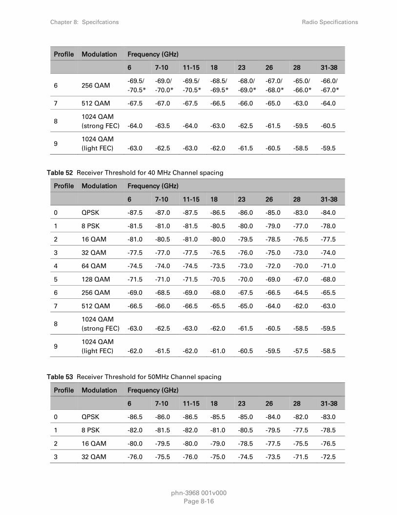
Chapter 8: Specifcations Radio Specifications
phn-3968 001v000
Page 8-16
Profile Modulation Frequency (GHz)
6 7-10 11-15 18 23 26 28 31-38
6 256 QAM -69.5/
-70.5*
-69.0/
-70.0*
-69.5/
-70.5*
-68.5/
-69.5*
-68.0/
-69.0*
-67.0/
-68.0*
-65.0/
-66.0*
-66.0/
-67.0*
7 512 QAM -67.5 -67.0 -67.5 -66.5 -66.0 -65.0 -63.0 -64.0
8 1024 QAM
(strong FEC) -64.0 -63.5 -64.0 -63.0 -62.5 -61.5 -59.5 -60.5
9 1024 QAM
(light FEC) -63.0 -62.5 -63.0 -62.0 -61.5 -60.5 -58.5 -59.5
Table 52 Receiver Threshold for 40 MHz Channel spacing
Profile Modulation Frequency (GHz)
6 7-10 11-15 18 23 26 28 31-38
0 QPSK -87.5 -87.0 -87.5 -86.5 -86.0 -85.0 -83.0 -84.0
1 8 PSK -81.5 -81.0 -81.5 -80.5 -80.0 -79.0 -77.0 -78.0
2 16 QAM -81.0 -80.5 -81.0 -80.0 -79.5 -78.5 -76.5 -77.5
3 32 QAM -77.5 -77.0 -77.5 -76.5 -76.0 -75.0 -73.0 -74.0
4 64 QAM -74.5 -74.0 -74.5 -73.5 -73.0 -72.0 -70.0 -71.0
5 128 QAM -71.5 -71.0 -71.5 -70.5 -70.0 -69.0 -67.0 -68.0
6 256 QAM -69.0 -68.5 -69.0 -68.0 -67.5 -66.5 -64.5 -65.5
7 512 QAM -66.5 -66.0 -66.5 -65.5 -65.0 -64.0 -62.0 -63.0
8 1024 QAM
(strong FEC) -63.0 -62.5 -63.0 -62.0 -61.5 -60.5 -58.5 -59.5
9 1024 QAM
(light FEC) -62.0 -61.5 -62.0 -61.0 -60.5 -59.5 -57.5 -58.5
Table 53 Receiver Threshold for 50MHz Channel spacing
Profile Modulation Frequency (GHz)
6 7-10 11-15 18 23 26 28 31-38
0 QPSK -86.5 -86.0 -86.5 -85.5 -85.0 -84.0 -82.0 -83.0
1 8 PSK -82.0 -81.5 -82.0 -81.0 -80.5 -79.5 -77.5 -78.5
2 16 QAM -80.0 -79.5 -80.0 -79.0 -78.5 -77.5 -75.5 -76.5
3 32 QAM -76.0 -75.5 -76.0 -75.0 -74.5 -73.5 -71.5 -72.5

Chapter 8: Specifcations Radio Specifications
phn-3968 001v000
Page 8-17
Profile Modulation Frequency (GHz)
6 7-10 11-15 18 23 26 28 31-38
4 64 QAM -73.5 -73.0 -73.5 -72.5 -72.0 -71.0 -69.0 -70.0
5 128 QAM -70.5 -70.0 -70.5 -69.5 -69.0 -68.0 -66.0 -67.0
6 256 QAM -67.5 -67.0 -67.5 -66.5 -66.0 -65.0 -63.0 -64.0
7 512 QAM -65.0 -64.5 -65.0 -64.0 -63.5 -62.5 -60.5 -61.5
8 1024 QAM
(strong FEC) -62.0 -61.5 -62.0 -61.0 -60.5 -59.5 -57.5 -58.5
9 1024 QAM
(light FEC) -61.0 -60.5 -61.0 -60.0 -59.5 -58.5 -56.5 -57.5
Note
50 MHz support is planned for future release.
Table 54 Receiver Threshold for 56 MHz Channel spacing
Profile Modulation Frequency (GHz)
6 7-10 11-15 18 23 26 28 31-38
0 QPSK -85.5 -85.0 -85.5 -84.5 -84.0 -83.0 -81.0 -82.0
1 8 PSK -81.5 -81.0 -81.5 -80.5 -80.0 -79.0 -77.0 -78.0
2 16 QAM -79.0 -78.5 -79.0 -78.0 -77.5 -76.5 -74.5 -75.5
3 32 QAM -75.5 -75.0 -75.5 -74.5 -74.0 -73.0 -71.0 -72.0
4 64 QAM -72.5 -72.0 -72.5 -71.5 -71.0 -70.0 -68.0 -69.0
5 128 QAM -69.5 -69.0 -69.5 -68.5 -68.0 -67.0 -65.0 -66.0
6 256 QAM -66.5 -66.0 -66.5 -65.5 -65.0 -64.0 -62.0 -63.0
7 512 QAM -64.5 -64.0 -64.5 -63.5 -63.0 -62.0 -60.0 -61.0
8 1024 QAM
(strong FEC) -61.0 -60.5 -61.0 -60.0 -59.5 -58.5 -56.5 -57.5
9 1024 QAM
(light FEC) -60 -59.5 -60 -59 -58.5 -57.5 -55.5 -56.5
10 2048 QAM -55.5 -55 -55.5 -54.5 -54 -53 -51 -52
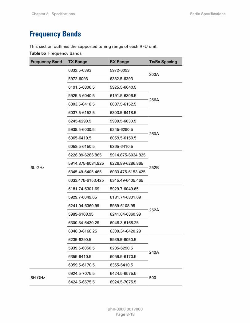
Chapter 8: Specifcations Radio Specifications
phn-3968 001v000
Page 8-18
Frequency Bands
This section outlines the supported tuning range of each RFU unit.
Table 55 Frequency Bands
Frequency Band TX Range RX Range Tx/Rx Spacing
6L GHz
6332.5-6393 5972-6093 300A
5972-6093 6332.5-6393
6191.5-6306.5 5925.5-6040.5
266A 5925.5-6040.5 6191.5-6306.5
6303.5-6418.5 6037.5-6152.5
6037.5-6152.5 6303.5-6418.5
6245-6290.5 5939.5-6030.5
260A 5939.5-6030.5 6245-6290.5
6365-6410.5 6059.5-6150.5
6059.5-6150.5 6365-6410.5
6226.89-6286.865 5914.875-6034.825
252B 5914.875-6034.825 6226.89-6286.865
6345.49-6405.465 6033.475-6153.425
6033.475-6153.425 6345.49-6405.465
6181.74-6301.69 5929.7-6049.65
252A
5929.7-6049.65 6181.74-6301.69
6241.04-6360.99 5989-6108.95
5989-6108.95 6241.04-6360.99
6300.34-6420.29 6048.3-6168.25
6048.3-6168.25 6300.34-6420.29
6235-6290.5 5939.5-6050.5
240A 5939.5-6050.5 6235-6290.5
6355-6410.5 6059.5-6170.5
6059.5-6170.5 6355-6410.5
6H GHz 6924.5-7075.5 6424.5-6575.5
500 6424.5-6575.5 6924.5-7075.5

Chapter 8: Specifcations Radio Specifications
phn-3968 001v000
Page 8-19
Frequency Band TX Range RX Range Tx/Rx Spacing
7032.5-7091.5 6692.5-6751.5 340C
6692.5-6751.5 7032.5-7091.5
6764.5-6915.5 6424.5-6575.5
340B 6424.5-6575.5 6764.5-6915.5
6924.5-7075.5 6584.5-6735.5
6584.5-6735.5 6924.5-7075.5
6781-6939 6441-6599
340A 6441-6599 6781-6939
6941-7099 6601-6759
6601-6759 6941-7099
6707.5-6772.5 6537.5-6612.5
160A
6537.5-6612.5 6707.5-6772.5
6767.5-6832.5 6607.5-6672.5
6607.5-6672.5 6767.5-6832.5
6827.5-6872.5 6667.5-6712.5
6667.5-6712.5 6827.5-6872.5
7 GHz
7783.5-7898.5 7538.5-7653.5
7538.5-7653.5 7783.5-7898.5
7301.5-7388.5 7105.5-7192.5
196A 7105.5-7192.5 7301.5-7388.5
7357.5-7444.5 7161.5-7248.5
7161.5-7248.5 7357.5-7444.5
7440.5-7499.5 7622.5-7681.5
7678.5-7737.5 7496.5-7555.5
7496.5-7555.5 7678.5-7737.5
7580.5-7639.5 7412.5-7471.5
168C
7412.5-7471.5 7580.5-7639.5
7608.5-7667.5 7440.5-7499.5
7440.5-7499.5 7608.5-7667.5
7664.5-7723.5 7496.5-7555.5

Chapter 8: Specifcations Radio Specifications
phn-3968 001v000
Page 8-20
Frequency Band TX Range RX Range Tx/Rx Spacing
7496.5-7555.5 7664.5-7723.5
7609.5-7668.5 7441.5-7500.5
168B
7441.5-7500.5 7609.5-7668.5
7637.5-7696.5 7469.5-7528.5
7469.5-7528.5 7637.5-7696.5
7693.5-7752.5 7525.5-7584.5
7525.5-7584.5 7693.5-7752.5
7273.5-7332.5 7105.5-7164.5
168A
7105.5-7164.5 7273.5-7332.5
7301.5-7360.5 7133.5-7192.5
7133.5-7192.5 7301.5-7360.5
7357.5-7416.5 7189.5-7248.5
7189.5-7248.5 7357.5-7416.5
7280.5-7339.5 7119.5-7178.5
161P
7119.5-7178.5 7280.5-7339.5
7308.5-7367.5 7147.5-7206.5
7147.5-7206.5 7308.5-7367.5
7336.5-7395.5 7175.5-7234.5
7175.5-7234.5 7336.5-7395.5
7364.5-7423.5 7203.5-7262.5
7203.5-7262.5 7364.5-7423.5
7597.5-7622.5 7436.5-7461.5
161O 7436.5-7461.5 7597.5-7622.5
7681.5-7706.5 7520.5-7545.5
7520.5-7545.5 7681.5-7706.5
7587.5-7646.5 7426.5-7485.5
161M 7426.5-7485.5 7587.5-7646.5
7615.5-7674.5 7454.5-7513.5
7454.5-7513.5 7615.5-7674.5
7643.5-7702.5 7482.5-7541.5 161K

Chapter 8: Specifcations Radio Specifications
phn-3968 001v000
Page 8-21
Frequency Band TX Range RX Range Tx/Rx Spacing
7482.5-7541.5 7643.5-7702.5
7671.5-7730.5 7510.5-7569.5
7510.5-7569.5 7671.5-7730.5
7580.5-7639.5 7419.5-7478.5
161J
7419.5-7478.5 7580.5-7639.5
7608.5-7667.5 7447.5-7506.5
7447.5-7506.5 7608.5-7667.5
7664.5-7723.5 7503.5-7562.5
7503.5-7562.5 7664.5-7723.5
7580.5-7639.5 7419.5-7478.5
161I
7419.5-7478.5 7580.5-7639.5
7608.5-7667.5 7447.5-7506.5
7447.5-7506.5 7608.5-7667.5
7664.5-7723.5 7503.5-7562.5
7503.5-7562.5 7664.5-7723.5
7273.5-7353.5 7112.5-7192.5
161F
7112.5-7192.5 7273.5-7353.5
7322.5-7402.5 7161.5-7241.5
7161.5-7241.5 7322.5-7402.5
7573.5-7653.5 7412.5-7492.5
7412.5-7492.5 7573.5-7653.5
7622.5-7702.5 7461.5-7541.5
7461.5-7541.5 7622.5-7702.5
7709-7768 7548-7607
161D
7548-7607 7709-7768
7737-7796 7576-7635
7576-7635 7737-7796
7765-7824 7604-7663
7604-7663 7765-7824
7793-7852 7632-7691

Chapter 8: Specifcations Radio Specifications
phn-3968 001v000
Page 8-22
Frequency Band TX Range RX Range Tx/Rx Spacing
7632-7691 7793-7852
7584-7643 7423-7482
161C
7423-7482 7584-7643
7612-7671 7451-7510
7451-7510 7612-7671
7640-7699 7479-7538
7479-7538 7640-7699
7668-7727 7507-7566
7507-7566 7668-7727
7409-7468 7248-7307
161B
7248-7307 7409-7468
7437-7496 7276-7335
7276-7335 7437-7496
7465-7524 7304-7363
7304-7363 7465-7524
7493-7552 7332-7391
7332-7391 7493-7552
7284-7343 7123-7182
161A
7123-7182 7284-7343
7312-7371 7151-7210
7151-7210 7312-7371
7340-7399 7179-7238
7179-7238 7340-7399
7368-7427 7207-7266
7207-7266 7368-7427
7280.5-7339.5 7126.5-7185.5
154C
7126.5-7185.5 7280.5-7339.5
7308.5-7367.5 7154.5-7213.5
7154.5-7213.5 7308.5-7367.5
7336.5-7395.5 7182.5-7241.5

Chapter 8: Specifcations Radio Specifications
phn-3968 001v000
Page 8-23
Frequency Band TX Range RX Range Tx/Rx Spacing
7182.5-7241.5 7336.5-7395.5
7364.5-7423.5 7210.5-7269.5
7210.5-7269.5 7364.5-7423.5
7594.5-7653.5 7440.5-7499.5
154B
7440.5-7499.5 7594.5-7653.5
7622.5-7681.5 7468.5-7527.5
7468.5-7527.5 7622.5-7681.5
7678.5-7737.5 7524.5-7583.5
7524.5-7583.5 7678.5-7737.5
7580.5-7639.5 7426.5-7485.5
154A
7426.5-7485.5 7580.5-7639.5
7608.5-7667.5 7454.5-7513.5
7454.5-7513.5 7608.5-7667.5
7636.5-7695.5 7482.5-7541.5
7482.5-7541.5 7636.5-7695.5
7664.5-7723.5 7510.5-7569.5
7510.5-7569.5 7664.5-7723.5
8 GHz
8396.5-8455.5 8277.5-8336.5
119A 8277.5-8336.5 8396.5-8455.5
8438.5 – 8497.5 8319.5 – 8378.5
8319.5 – 8378.5 8438.5 – 8497.5
8274.5-8305.5 7744.5-7775.5 530A
7744.5-7775.5 8274.5-8305.5
8304.5-8395.5 7804.5-7895.5 500A
7804.5-7895.5 8304.5-8395.5
8023-8186.32 7711.68-7875 311C-J
7711.68-7875 8023-8186.32
8028.695-8148.645 7717.375-7837.325
311B 7717.375-7837.325 8028.695-8148.645
8147.295-8267.245 7835.975-7955.925
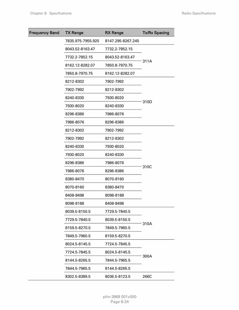
Chapter 8: Specifcations Radio Specifications
phn-3968 001v000
Page 8-24
Frequency Band TX Range RX Range Tx/Rx Spacing
7835.975-7955.925 8147.295-8267.245
8043.52-8163.47 7732.2-7852.15
311A 7732.2-7852.15 8043.52-8163.47
8162.12-8282.07 7850.8-7970.75
7850.8-7970.75 8162.12-8282.07
8212-8302 7902-7992
310D
7902-7992 8212-8302
8240-8330 7930-8020
7930-8020 8240-8330
8296-8386 7986-8076
7986-8076 8296-8386
8212-8302 7902-7992
310C
7902-7992 8212-8302
8240-8330 7930-8020
7930-8020 8240-8330
8296-8386 7986-8076
7986-8076 8296-8386
8380-8470 8070-8160
8070-8160 8380-8470
8408-8498 8098-8188
8098-8188 8408-8498
8039.5-8150.5 7729.5-7840.5
310A 7729.5-7840.5 8039.5-8150.5
8159.5-8270.5 7849.5-7960.5
7849.5-7960.5 8159.5-8270.5
8024.5-8145.5 7724.5-7845.5
300A 7724.5-7845.5 8024.5-8145.5
8144.5-8265.5 7844.5-7965.5
7844.5-7965.5 8144.5-8265.5
8302.5-8389.5 8036.5-8123.5 266C

Chapter 8: Specifcations Radio Specifications
phn-3968 001v000
Page 8-25
Frequency Band TX Range RX Range Tx/Rx Spacing
8036.5-8123.5 8302.5-8389.5
8190.5-8277.5 7924.5-8011.5 266B
7924.5-8011.5 8190.5-8277.5
8176.5-8291.5 7910.5-8025.5
266A 7910.5-8025.5 8176.5-8291.5
8288.5-8403.5 8022.5-8137.5
8022.5-8137.5 8288.5-8403.5
8226.52-8287.52 7974.5-8035.5 252A
7974.5-8035.5 8226.52-8287.52
8270.5-8349.5 8020.5-8099.5 250A
10 GHz
10501-10563 10333-10395
168A
10333-10395 10501-10563
10529-10591 10361-10423
10361-10423 10529-10591
10585-10647 10417-10479
10417-10479 10585-10647
10501-10647 10151-10297 350A
10151-10297 10501-10647
10498-10652 10148-10302 350B
10148-10302 10498-10652
10561-10707 10011-10157
550A 10011-10157 10561-10707
10701-10847 10151-10297
10151-10297 10701-10847
10590-10622 10499-10531
91A
10499-10531 10590-10622
10618-10649 10527-10558
10527-10558 10618-10649
10646-10677 10555-10586

Chapter 8: Specifcations Radio Specifications
phn-3968 001v000
Page 8-26
Frequency Band TX Range RX Range Tx/Rx Spacing
10555-10586 10646-10677
11 GHz
11425-11725 10915-11207
All 10915-11207 11425-11725
11185-11485 10700-10950
10695-10955 11185-11485
13 GHz
13002-13141 12747-12866
266 12747-12866 13002-13141
13127-13246 12858-12990
12858-12990 13127-13246
12807-12919 13073-13185 266A
13073-13185 12807-12919
12700-12775 12900-13000
200
12900-13000 12700-12775
12750-12825 12950-13050
12950-13050 12750-12825
12800-12870 13000-13100
13000-13100 12800-12870
12850-12925 13050-13150
13050-13150 12850-12925
15 GHz
15110-15348 14620-14858
490 14620-14858 15110-15348
14887-15117 14397-14627
14397-14627 14887-15117
15144-15341 14500-14697 644
14500-14697 15144-15341
14975-15135 14500-14660 475
14500-14660 14975-15135

Chapter 8: Specifcations Radio Specifications
phn-3968 001v000
Page 8-27
Frequency Band TX Range RX Range Tx/Rx Spacing
15135-15295 14660-14820
14660-14820 15135-15295
14921-15145 14501-14725
420 14501-14725 14921-15145
15117-15341 14697-14921
14697-14921 15117-15341
14963-15075 14648-14760
315 14648-14760 14963-15075
15047-15159 14732-14844
14732-14844 15047-15159
15229-15375 14500-14647 728
14500-14647 15229-15375
18 GHz
19160-19700 18126-18690
1010 18126-18690 19160-19700
18710-19220 17700-18200
17700-18200 18710-19220
19260-19700 17700-18140 1560
17700-18140 19260-19700
23 GHz
23000-23600 22000-22600 1008
22000-22600 23000-23600
22400-23000 21200-21800
1232 /1200 21200-21800 22400-23000
23000-23600 21800-22400
21800-22400 23000-23600
26 GHz 25530-26030 24520-25030
1008 24520-25030 25530-26030
25980-26480 24970-25480

Chapter 8: Specifcations Radio Specifications
phn-3968 001v000
Page 8-28
Frequency Band TX Range RX Range Tx/Rx Spacing
24970-25480 25980-26480
25266-25350 24466-24550
800 24466-24550 25266-25350
25050-25250 24250-24450
24250-24450 25050-25250
28 GHz
28150-28350 27700-27900
450 27700-27900 28150-28350
27950-28150 27500-27700
27500-27700 27950-28150
28050-28200 27700-27850 350
27700-27850 28050-28200
27960-28110 27610-27760
27610-27760 27960-28110
28090-28315 27600-27825 490
27600-27825 28090-28315
29004-29453 27996-28445 1008
27996-28445 29004-29453
28556-29005 27548-27997
27548-27997 28556-29005
29100-29125 29225-29250 125
29225-29250 29100-29125
31 GHz 31000-31085 31215-31300 175
31215-31300 31000-31085
32 GHz
31815-32207 32627-33019 812
32627-33019 31815-32207
32179-32571 32991-33383
32991-33383 32179-32571
38 GHz
38820-39440 37560-38180 1260

Chapter 8: Specifcations Radio Specifications
phn-3968 001v000
Page 8-29
Frequency Band TX Range RX Range Tx/Rx Spacing
37560-38180 38820-39440
38316-38936 37045-37676
37045-37676 38316-38936
39650-40000 38950-39300
700
38950-39300 39500-40000
39300-39650 38600-38950
38600-38950 39300-39650
37700-38050 37000-37350
37000-37350 37700-38050
38050-38400 37350-37700
37350-37700 38050-38400

Chapter 8: Specifcations Network Specifications
phn-3968 001v000
Page 8-30
Network Specifications
Ethernet Latency Specifications
Ethernet Latency – 7 MHz Channel Bandwidth
Table 56 Ethernet Latency 7 MHz Channel Bandwidth
ACM
Working
Point
Modulation Latency (usec) with GE Interface
Frame
Size
64 128 256 512 1024 1518
0 QPSK 924 987 1106 1353 1840 2317
1 8 PSK 678 718 799 969 1298 1623
2 16 QAM 525 549 604 728 962 1194
3 32 QAM 446 470 515 605 787 961
4 64 QAM 399 419 456 531 679 824
5 128 QAM 369 383 416 479 603 725
6 256 QAM 366 380 408 463 573 681
7 512 QAM 371 384 411 462 566 668
8 1024 QAM
(strong FEC)
352 366 390 439 538 633
9 1024 QAM
(light FEC)
349 360 384 430 524 613
Ethernet Latency – 14 MHz Channel Bandwidth
Table 57 Ethernet Latency 14 MHz Channel Bandwidth
ACM
Working
Point
Modulation Latency (usec) with GE Interface
Frame
Size
64 128 256 512 1024 1518
0 QPSK 460 480 534 647 867 1086
1 8 PSK 346 364 402 479 629 778
2 16 QAM 265 278 307 364 477 588
3 32 QAM 233 244 267 312 401 487

Chapter 8: Specifcations Network Specifications
phn-3968 001v000
Page 8-31
ACM
Working
Point
Modulation Latency (usec) with GE Interface
Frame
Size
64 128 256 512 1024 1518
4 64 QAM 213 222 241 279 353 426
5 128 QAM 193 202 219 251 315 377
6 256 QAM 177 184 199 228 286 341
7 512 QAM 209 216 230 256 310 361
8 1024 QAM
(strong FEC)
195 202 215 241 292 341
9 1024 QAM
(light FEC)
190 197 210 234 283 330
Ethernet Latency – 28 MHz Channel Bandwidth
Table 58 Ethernet Latency 28 MHz Channel Bandwidth
ACM
Working
Point
Modulation Latency (usec) with GE Interface
Frame
Size
64 128 256 512 1024 1518
0 QPSK 154 169 198 257 373 484
1 8 PSK 130 141 162 204 286 363
2 16 QAM 109 117 133 166 231 290
3 32 QAM 105 111 125 152 204 252
4 64 QAM 101 107 119 142 187 228
5 128 QAM 95 100 110 131 171 207
6 256 QAM 89 94 103 123 160 193
7 512 QAM 113 117 126 145 179 210
8 1024 QAM
(strong FEC)
104 108 117 135 168 198
9 1024 QAM
(light FEC)
106 110 118 136 168 197

Chapter 8: Specifcations Network Specifications
phn-3968 001v000
Page 8-32
Ethernet Latency – 30 MHz Channel Bandwidth
Table 59 Ethernet Latency 30 MHz Channel Bandwidth
ACM
Working
Point
Modulation Latency (usec) with GE Interface
Frame
Size
64 128 256 512 1024 1280 1518
0 QPSK 228 242 270 326 439 495 548
1 8 PSK 171 181 202 242 323 363 400
2 16 QAM 138 145 160 190 250 280 309
3 32 QAM 124 130 142 166 214 238 260
4 64 QAM 115 120 130 151 191 212 231
5 128 QAM 105 109 118 136 172 190 206
6 256 QAM 110 115 122 138 171 187 202
7 512 QAM 116 120 128 143 174 189 204.2
8 1024 QAM
(strong FEC)
107 111 118 133 162 177 190
9 1024 QAM
(light FEC)
110 113 120 134 162 176 190
Ethernet Latency – 40 MHz Channel Bandwidth
Table 60 Ethernet Latency 40 MHz Channel Bandwidth
ACM
Working
Point
Modulation Latency (usec) with GE Interface
Frame
Size
64 128 256 512 1024 1280 1518
0 QPSK 194 206 230 278 373 420 465
1 8 PSK 147 156 173 208 277 311 342
2 16 QAM 120 126 139 165 216 242 267
3 32 QAM 108 113 124 144 186 207 226
4 64 QAM 100 104 113 131 166 185 201
5 128 QAM 92 96 104 120 151 167 181
6 256 QAM 95 100 106 120 149 163 177
7 512 QAM 100 104 111 124 151 165 178

Chapter 8: Specifcations Network Specifications
phn-3968 001v000
Page 8-33
ACM
Working
Point
Modulation Latency (usec) with GE Interface
Frame
Size
64 128 256 512 1024 1280 1518
8 1024 QAM
(strong FEC)
93 96 102 116 141 155 166
9 1024 QAM
(light FEC)
95 97 104 116 141 154 166
Ethernet Latency – 50 MHz Channel Bandwidth
Table 61 Ethernet Latency 50 MHz Channel Bandwidth
ACM
Working
Point
Modulation Latency (usec) with GE Interface
Frame
Size
64 128 256 512 1024 1280 1518
0 QPSK 127 135 150 180 240 270 298
1 8 PSK 100 105 116 139 183 205 226
2 16 QAM 83 88 96 114 149 166 182
3 32 QAM 76 80 87 101 130 145 158
4 64 QAM 70 73 79 92 117 130 141
5 128 QAM 67 70 75 87 109 120 131
6 256 QAM 66 69 74 85 106 116 126
7 512 QAM 68 71 76 86 106 116 125
8 1024 QAM
(strong FEC)
64 66 71 81 100 110 119
9 1024 QAM
(light FEC)
64 66 71 81 99 109 117
Note
50 MHz support is planned for future release.

Chapter 8: Specifcations Network Specifications
phn-3968 001v000
Page 8-34
Ethernet Latency – 56 MHz Channel Bandwidth
Table 62 Ethernet Latency 56 MHz Channel Bandwidth
ACM
Working
Point
Modulation Latency (usec) with GE Interface
Frame
Size
64 128 256 512 1024 1518
0 QPSK 94 102 119 152 216 275
1 8 PSK 83 89 102 127 174 218
2 16 QAM 72 77 87 108 146 182
3 32 QAM 69 73 82 99 133 162
4 64 QAM 66 69 77 93 123 149
5 128 QAM 65 68 75 90 116 140
6 256 QAM 61 64 71 84 110 132
7 512 QAM 69 72 78 92 116 137
8 1024 QAM
(strong FEC)
65 68 74 87 110 131
Ethernet Specifications
Ethernet Interface Specifications
Table 63 Ethernet Interface Specifications
Supported Ethernet Interfaces for
Traffic
4 x 10/100/1000Base-T (RJ-45) and
2 x 1000base-X (SFP)
Supported Ethernet Interfaces for
Management 2 x 10/100 Base-T (RJ-45)
Supported SFP Types Optical 1000Base-LX (1310 nm) or
SX (850 nm)
Carrier Ethernet Functionality
Table 64 Carrier Ethernet Functionality
Switching capacity 8 Gbps
"Jumbo" Frame Support Up to 9600 Bytes

Chapter 8: Specifcations Network Specifications
phn-3968 001v000
Page 8-35
General Header De-Duplication45
Integrated Carrier Ethernet
Switch
MAC address learning with 128K MAC addresses
802.1ad provider bridges (QinQ)
802.3ad link aggregation
QoS
Advanced CoS classification and remarking
Per interface CoS based packet queuing/buffering (8 queues)
Per queue statistics
Tail-drop and WRED with CIR/EIR support
Flexible scheduling schemes (SP/WFQ/Hierarchical)
Per interface and per queue traffic shaping
Hierarchical-QoS (H-QoS) – 2K service level queues46
2 Gbit packet buffer
Network resiliency MSTP
ERP (G.8032)
Service OAM FM (Y.1731/802.1ag) 47
PM (Y.1731) 48
Performance Monitoring
Per port Ethernet counters (RMON/RMON2)
Radio ACM statistics
Enhanced radio Ethernet statistics (Frame Error Rate,
Throughput, Capacity, Utilization)
Synchronization Specifications
Table 65 Synchronization Specifications
Sync Unit / SyncE ITU-T G.8261
45 Planned for future release.
46 Planned for future release.
47 Planned for future release.
48 Planned for future release.

Chapter 8: Specifcations Power Specifications
phn-3968 001v000
Page 8-36
Power Specifications
Power Input Specifications
Table 66 Power Input Specifications
IDU Standard Input -48 VDC
IDU DC Input range -40 to --60 VDC
RFU-C Operating Range -40.5 to -59 VDC
Power Consumption Specifications
The following table shows the maximum power consumption for PTP 820G IDU and supported
RFUs. The maximum power consumption for the entire system is the sum of the IDU and the RFUs
connecting to it.
Table 67 Power Consumption Specifications
Configuration Power (W) Comments
IDU Eth-only with single modem 23.5W
Addition for second modem 2.9W
Addition for 16 DS1s 11W
RFU-C
6-26 GHz 1+0: 22
1+1: 39 RFU only.
28-38 GHz 1+0: 26
1+1: 43 RFU only.

Chapter 8: Specifcations Physical and Electrical Specifications
phn-3968 001v000
Page 8-37
Physical and Electrical Specifications
Mediation Device Losses
Table 68 RFU-C Mediation Device Losses
Note
The antenna interface is always the RFU-C interface.
If other antennas are to be used, an adaptor with a 0.1 dB loss should be considered.
TDM Specifications
DS1/E1 Interface Specifications
Table 69 DS1 Interface Specifications
Interface Type DS1/E1
Number of Ports 16 x DS1s /E1
Connector Type MDR 69-pin
Framing Framed / Unframed
Coding HDB3
Configuration Interfaces 6-8
GHz 11 GHz
13-
15
GHz
18-
26
GHz
28-38
GHz
1+0 Direct Mount Integrated
antenna 0.2 0.2 0.4 0.5 0.5
1+1 HSB
Direct Mount
Main Path 1.6 1.6 1.8 1.8 1.8
with
asymmetrical
coupler
Secondary Path 6 6 6 6 6
2+0 DP (OMT) Direct Mount Integrated
antenna 0.5 0.5 0.5 0.5 0.5
2+0/1+1 FD SP Integrated antenna 3.8 3.8 3.9 4 4

Chapter 8: Specifcations Physical and Electrical Specifications
phn-3968 001v000
Page 8-38
Line Impedance
120 ohm/100 ohm balanced. Optional 75 ohm
unbalanced supported using panel with integrated
impedance adaption.
Compatible
Standards
ITU-T G.703, G.736, G.775, G.823, G.824, G.828,
ITU-T I.432, ETSI ETS 300 147, ETS 300 417,
Bellcore GR-253-core, TR-NWT-000499
E1 Cross Connect
Table 70 E1 Interface Specifications
E1 Cross Connect Capacity 256 E1 Trails (VCs)
E1 Trails Protection 1+1 / 1:1
Mechanical Specifications
Table 71 IDU Mechanical Specifications
IDU Dimensions
Height: 1.73” (1RU)
Width: 16.77”
Depth: 7.08”
Weight: 5.5 lbs
IDU-RFU Connection
Coaxial cable RG-223 (300 ft), Belden 9914/RG-8
(1000 ft) or equivalent, TNC connectors to the
IDU, N-type connectors (male) to the RFU.
Table 72 RFU-C Mechanical Specifications
RFU-C Dimensions
Height: 7.87 inches
Width: 7.87 inches
Depth: 3.35 inches
Weight: 9 lbs
RFU-C Standard
Mounting OD Pole
50 mm-120 mm/2”-4.5” (subject to vendor and
antenna size)

Chapter 8: Specifcations Physical and Electrical Specifications
phn-3968 001v000
Page 8-39
Environmental Specifications
Environmental Specifications for IDU
Temperature:
o 23F to 131F – Temperature range for continuous operating temperature with high
reliability.
o -13F to 149F – Temperature range for exceptional temperatures, tested successfully, with
limited margins.
Note
Cold startup requires at least 23F
Humidity: 5%RH to 95%RH
Environmental Specifications for RFU
Temperature:
o -27F to 131F – Temperature range for continuous operating temperature with high
reliability:
o -49F to 140F – Temperature range for exceptional temperatures; tested successfully, with
limited margins:
Humidity: 5%RH to 100%RH
Supported Antenna Types
RFU-C uses Andrew and Radio Wave antennas.
RFU-C can be mounted directly for all frequencies (6-38 GHz) using the following antenna types
(for integrated antennas, specific antennas PNs are required):
Andrew: VHLP series
Radio Wave

phn-3968 001v000
Page I
Glossary
Term Definition
ACM Adaptive Coding and Modulation
ACR Adaptive Clock Recovery
AES Advanced Encryption Standard
AIS Alarm Indication Signal
ATPC Automatic Tx Power Control
BBS Baseband Switching
BER Bit Error Ratio
BLSR Bidirectional Line Switch Ring
BPDU Bridge Protocol Data Units
BWA Broadband Wireless Access
CBS Committed Burst Size
CCDP Co-channel dual polarization
CE Customer Equipment
CET Carrier-Ethernet Transport
CFM Connectivity Fault Management
CIR Committed Information Rate
CLI Command Line Interface
CoS Class of Service
DA Destination Address
DSCP Differentiated Service Code Point
EBS Excess Burst Size
EIR Excess Information Rate
EPL Ethernet Private Line
EVPL Ethernet Virtual Private Line
EVC Ethernet Virtual Connection
FTP (SFTP) File Transfer Protocol (Secured File Transfer Protocol)

Glossary
phn-3968 001v000
Page II
Term Definition
GE Gigabit Ethernet
GMT Greenwich Mean Time
HSB Hot Standby
HTTP (HTTPS) Hypertext Transfer Protocol (Secured HTTP)
IDC Indoor Controller
IDU Indoor unit
LANs Local area networks
LMS License Management System
LOC Loss of Carrier
LOF Loss Of Frame
LOS Loss of Signal
LTE Long-Term Evolution
MAID Maintenance Association (MA) Identifier (ID)
MEN Metro Ethernet Network
MPLS Multiprotocol Label Switching
MRU Maximum Receive Unit
MSP Multiplex Section Protection
MSTI Multiple Spanning Tree Instance
MSTP Multiple Spanning Tree Protocol
MTU Maximum Transmit Capability
NMS Network Management System
NTP Network Time Protocol
OAM Operation Administration & Maintenance (Protocols)
ODU Out Door Unit
OOF Out-of-Frame
PBB-TE Provider Backbone Bridge Traffic Engineering
PBS Peak Burst Rate
PDV Packed Delay Variation
PIR Peak Information Rate
PM Performance Monitoring

Glossary
phn-3968 001v000
Page III
Term Definition
PN Provider Network (Port)
PSN Frame Switched Network
PTP Precision Timing-Protocol
PW Pseudowire
QoE Quality of-Experience
QoS Quality of Service
RBAC Role-Based Access Control
RDI Reverse Defect Indication
RFU Radio Frequency Unit
RMON Ethernet Statistics
RSL Received Signal Level
RSTP Rapid Spanning Tree Protocol
SAP Service Access Point
SFTP Secure FTP
SLA Service level agreements
SNMP Simple Network Management Protocol
SNP Service Network Point
SNTP Simple Network Time Protocol
SP Service Point
STP Spanning Tree Protocol
SSH Secured Shell (Protocol)
SSM Synchronization Status Messages
SyncE Synchronous Ethernet
TC Traffic Class
TOS Type of Service
UNI User Network Interface
UTC Coordinated Universal Time
VC Virtual Containers
Web EMS Web-Based Element Management System
WG Wave guide

Glossary
phn-3968 001v000
Page IV
Term Definition
WFQ Weighted Fair Queue
WRED Weighted Random Early Detection
XPIC Cross Polarization Interference Cancellation