PTN 910 Commissioning Guide
13
PTN 910 COMMISSION GUIDE PTN 910 COMMISSION GUIDE CONFIDENTIAL © COPYRIGHT (2012) Page 1 of 13
-
Upload
qiang-yang -
Category
Documents
-
view
399 -
download
12
Transcript of PTN 910 Commissioning Guide
PTN 910 COMMISSION GUIDE
PTN 910 COMMISSION GUIDE
CONFIDENTIAL © COPYRIGHT (2012)
Page 1 of 10
PTN 910 COMMISSION GUIDE
Huawei Technologies Co., Ltd. provides customers with comprehensive technical support and service. For assistance, please contact our local office or company headquarters.
Huawei Technologies Co., Ltd.
Address: Huawei Industrial Base
Bantian, Longgang
Shenzhen 518129
People’s Republic of China
Website: http://www.huawei.com
Email: [email protected]
Copyright © Huawei Technologies Co., Ltd. 2012. All rights reserved.
No part of this document may be reproduced or transmitted in any form or by any means without prior written consent of Huawei Technologies Co., Ltd.
Trademarks and Permissions
and other Huawei trademarks are trademarks of Huawei Technologies Co., Ltd.
All other trademarks and trade names mentioned in this document are the properties of their respective holders.
Notice
Every effort has been made in the preparation of this document to ensure accuracy of the contents, but all statements, information, and recommendations in this document do not constitute the warranty of any kind, express or implied.
CONFIDENTIAL © COPYRIGHT (2012)
Page 2 of 10
PTN and BITS Commissioning Guide
1 PTN 910 status check
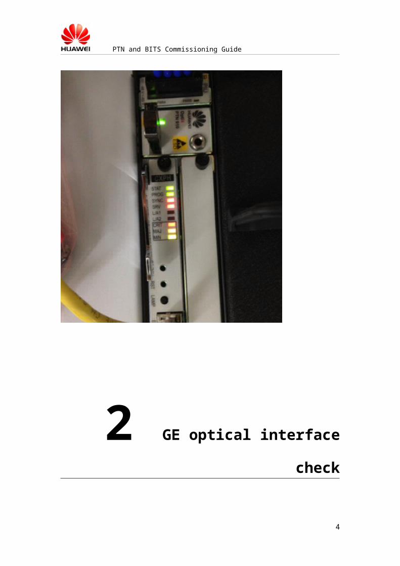
After powering up the PTN equipment, wait 3-5 minutes for the PTN to start up completely. Then the engineer should check the status of PTN indicators.
For PTN910: There are 9 indicators on the PTN CXPH board. The correct indicators status should be as shown below:
3
PTN and BITS Commissioning Guide
2 GE optical interface check
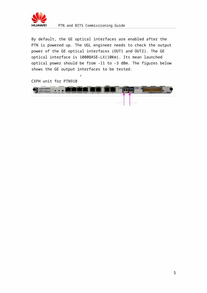
By default, the GE optical interfaces are enabled after the PTN is powered up. The UGL engineer needs to check the output power of the GE optical interfaces (OUT1 and OUT2). The GE optical interface is 1000BASE-LX(10Km). Its mean launched optical power should be from -11 to -3 dBm. The figures below shows the GE output interfaces to be tested.
CXPH unit for PTN910”
4
PTN and BITS Commissioning Guide
3 Configure the PTN 910
Parameters
The NE IP and GE interface IP should be configured to enable the remote communication and control of the PTN.UGL engineer should be responsible for the IP address configuration.
Step 1: Configure the IP address on the PCThe UGL engineer should first configure the laptop IP address to be 129.9.0.1 (IP mask 255.255.0.0)
Then the Ethernet interface of the laptop should be connect to the ETH/OAM interface of the PTN with cable.
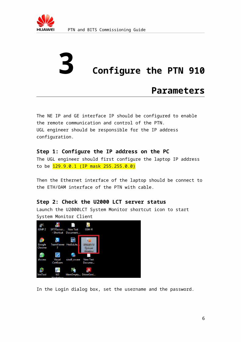
Step 2: Check the U2000 LCT server statusLaunch the U2000LCT System Monitor shortcut icon to start System Monitor Client
In the Login dialog box, set the username and the password.
5
PTN and BITS Commissioning Guide
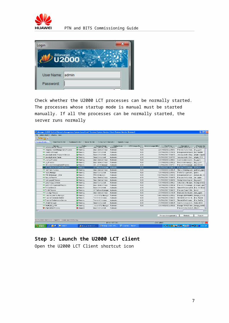
Check whether the U2000 LCT processes can be normally started. The processes whose startup mode is manual must be started manually. If all the processes can be normally started, the server runs normally
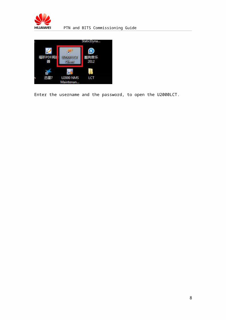
Step 3: Launch the U2000 LCT clientOpen the U2000 LCT Client shortcut icon
6
PTN and BITS Commissioning Guide
Enter the username and the password, to open the U2000LCT.
7
PTN and BITS Commissioning Guide
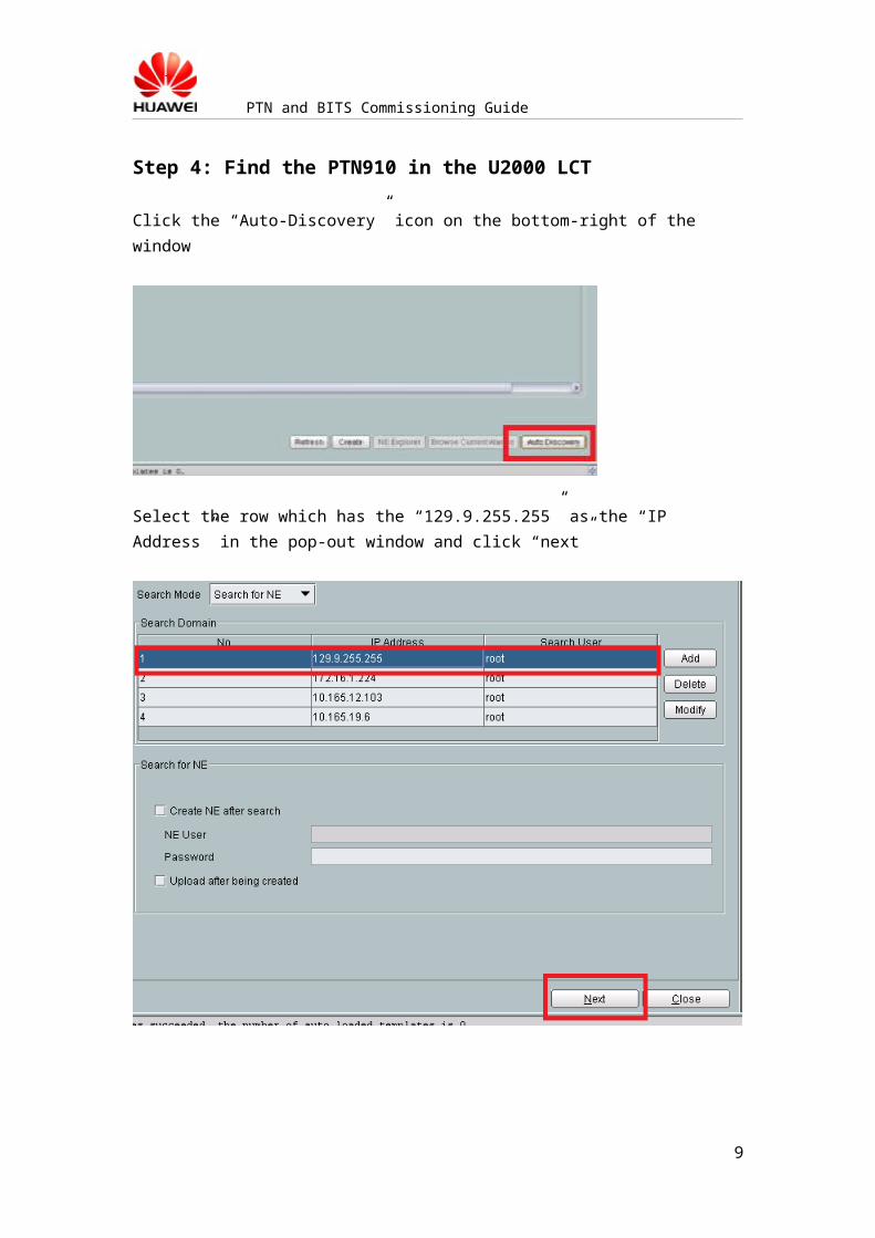
Step 4: Find the PTN910 in the U2000 LCT
Click the “Auto-Discovery” icon on the bottom-right of the window
Select the row which has the “129.9.255.255” as the “IP Address” in the pop-out window and click “next”
8
PTN and BITS Commissioning Guide
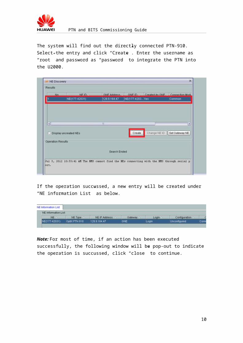
The system will find out the directly connected PTN-910. Select the entry and click “Create”. Enter the username as “root” and password as “password” to integrate the PTN into the U2000.
If the operation succussed, a new entry will be created under “NE information List” as below.
Note: For most of time, if an action has been executed successfully, the following window will be pop-out to indicate the operation is succussed, click “close” to continue.
9
PTN and BITS Commissioning Guide
Step 4: Upload the PTN-910 configuration
Right-click the new-created 910 entry and click “configuration”;In the new window, select the “Upload” radio button and click “Next” to upload the configuration.
In the new pop-out window, click “OK” to continue.
The system will finish the uploading process after the progress reach “100%”
10