PTC 285 Specification for Customer Premises 285 Specification for Customer Premises VDSL2 Splitters...
38
PTC 285 Specification for Customer Premises VDSL2 Splitters Access Standards Telecom New Zealand Limited Wellington NEW ZEALAND June 2010 iss4
Transcript of PTC 285 Specification for Customer Premises 285 Specification for Customer Premises VDSL2 Splitters...

PTC 285 Specification for Customer Premises VDSL2 Splitters Access Standards Telecom New Zealand Limited Wellington NEW ZEALAND June 2010 iss4
2 PTC 285 June 2010 iss4
CONTENTS FOREWORD 3 DISCLAIMER 3 1 SCOPE 4 2 GENERAL 6 3 DEFINITIONS 8 4 TELEPERMIT TECHNICAL REQUIREMENTS 11 4.1 Electrical Safety 11 4.2 EMC 11 4.3 DC Requirements 11 4.4 Ringing Frequency Requirements 11 4.5 Voice Frequency requirements 13 4.6 VDSL2 Frequency Requirements 17 4.7 Noise 21 4.8 Connection Methods and Physical Requirements 23 Appendix 1 Test Schedule 28 References ETSI TS 101 952-2-1 V1.1.1 (2002-11) Specification of the low pass part of VDSL/POTS splitters ETSI TS 101 952-2-2 V1.1.1 (2003-3) Specification of the high pass part of VDSL/POTS splitters ETSI TR 101 728 V1.2.1 (2005-05) Study for the specification of low pass filter section of POTS/ADSL splitters AS/ACIF S041:2005 Requirements for DSL Customer Equipment for connection to the Public Switched Telephone Network PTC273:2007 Requirements for ADSL2+ CPE PTC200:2006 Requirements for Connection of Customer Equipment to Analogue Lines PTC106:2008 Telecom Code of Practice For Residential type Generic Cabling Systems
3 PTC 285 June 2010 iss4
FOREWORD This specification defines the technical requirements for the grant of Telepermits for VDSL2 splitters for use in customer premises connected to various DSL services. When ADSL service was introduced in 2000, splitters were permanently installed at the ETP. A separate cable was run from the ETP to a jackpoint to which the ADSL modem was connected. The splitter was installed by a Telecom contractor and no customer installed option was available. This was largely due to the fact that other than the ETP, there was no suitable point in the house wiring where a splitter could be easily connected. In 2001 PTC 280 was published. This specification covered the requirements for distributed line filters. The ADSL signal was then available at all jackpoints in a house, with line filters required on all jackpoints with analogue telephones, faxes etc connected. This system had the advantage of flexibility in that the ADSL modem could be connected at any jackpoint, and installation required no specialist tools or personnel. The disadvantage of using line filters is that the ADSL signal is carried by the house wiring which may be adequate for voice frequency use but is often quite unsuitable for DSL frequencies. The main culprit is poor balance due to the 3 wire system which houses were wired to in New Zealand from 1983 until 1996. Much of the cable is susceptible to interference from the large number of noise sources found in the average home. Examples are light dimmers, switched mode power supplies, electric motor commutators, etc. This can cause severe performance degradation in ADSL performance, the degradation being worse when ADSL2+ or VDSL2 is deployed. In general it is not feasible to use line filters at all for VDSL2 and marginal for ADSL2+. This Specification defines the technical requirements for splitters which are suitable for ADSL, ADSL2+, and VDSL2 use. The splitters are designed to be connected via either a distribution cabinet (PTC 106) for star wired houses, or a Service Delivery Point (SDP) for legacy wired houses. TELECOM DISCLAIMER While every care has been taken, Telecom makes no representation or warranty, express or implied, with respect to the sufficiency, accuracy, or utility of any information contained in this Specification. Telecom expressly advises that the use of or reliance on such information is at the risk of the person concerned. Telecom shall not be liable for any loss (including consequential loss), damage, or injury incurred by any person or organization arising out of the sufficiency, accuracy, or utility of any such information or opinion.

4 PTC 285 June 2010 iss4
1 SCOPE This Specification will cover splitters suitable for VDSL2 transmission using frequencies up to 30 MHz. In addition to VDSL2 the splitter is also suitable for the following: ADSL (ITU-T Rec G.992.1) ADSL2 (ITU-T Rec G.992.3) ADSL2+ (ITU-T Rec G.992.5) READSL2 (ITU-T Rec G.992.3 Annex L M1) ADSL2+ extended upstream (ITU-T Rec G.992.3 Annex M) When considering the effectiveness of deploying the very high speeds which are theoretically possible, it should be remembered that just as ADSL2+ provides no advantage over ADSL at line lengths over about 4 km, VDSL2 similarly offers no advantage over ADSL2+ at line lengths over about 1500m. These very high speed DSL technologies are often only feasible within a single building. That is, a high density apartment building might have a high speed optical fibre feed to the building, with VDSL2 used to feed the individual tenants. Splitters are necessary to separate two services on the same line. For the purposes of this Specification these services are VDSL2 or one of the ADSL variatnts and Plain Old Telephone Service (POTS). A functional diagram showing the configuration of splitters and the two services is given in Figure 1.
COSplitter
CustomerPremisesSplitter
PSTN
POTSCPE
ATU-C(DSLAM)
ATU-R(xDSL
modem)
Access LineLine Line
DSL DSL
POTS POTS
Figure 1. Functional diagram of DSL Splitter configuration The specific requirements of the splitter are:
• Protect POTS CPE from interference from VDSL2 (ADSL) signals

5 PTC 285 June 2010 iss4
• Protect the VDSL2 (ADSL) service from POTS signals such as the effects of harmonics generated by CPE ringers, on-hook/off-hook transitions, dialing etc
• Protect the VDSL2 (ADSL) service from the effect of sudden impedance
change due to on-hook/off-hook transitions
• Isolate the VDSL2 (ADSL) service from unbalanced (about earth) access lines and house wiring. This helps reduce susceptibility to induced noise.
• Provide minimal attenuation and distortion at VDSL2 (ADSL) frequencies
between the line and VDSL2 (ADSL) ports
• Provide minimal attenuation and distortion at voice frequencies between the line and POTS ports
• Provide good impedance matching between the network and CPE at both
DSL and POTS frequencies This Specification defines minimum requirements for the above parameters. The structure of a VDSL2 (ADSL) splitter is given in figure 2.
Line port
DSLmodem
port
POTS CPEport
High pass filter(optional)
Low pass filter
Figure 2. Structure of VDSL2 (ADSL) splitter The high pass filter function may also contain circuitry to isolate the VDSL2 (ADSL) modem port from any unbalance on the line. The low pass filter function will also be designed to isolate the VDSL2 (ADSL) port from any unbalance on the POTS CPE port.
6 PTC 285 June 2010 iss4
2 GENERAL 2.1 Specification Format (1) General background information and requirements forming part of this Specification are printed in plain text in numbered clauses. Comments and notes intended for explanatory purposes are printed in italics and in a smaller font size, in unnumbered clauses, preceded with a “·” symbol. (2) The word “shall” indicates a mandatory requirement, all of which must be met in order to qualify for a Telepermit. Mandatory requirements are shaded for ease of reference. The word “should” indicates a non-mandatory recommendation of Telecom. The word “may” indicates an option having no consequence to Telecom. 2.2 Marketing Features This Specification does not define or restrict the design methods of splitters submitted for Telepermit nor the physical dimensions of such products. It simply defines the technical parameters that have to be met, the basic electrical interfaces and the information that needs to be provided to purchasers and installers. 2.3 Changes in PTC Specifications (1) Telecom will develop this specification to cover new or changed requirements with the aim of publishing such information as is necessary for suppliers to design product which will better meet customer requirements. (2) Telecom will publish this specification and later issues free of charge, on the Access standards website. Actual specification changes will be supplemented by further information in the Access Standards Newsletters, as and when required.
• The URL of the Access Standards Website is http://www.telepermit.co.nz (3) Where justified by the results of service experience, Telecom reserves the right to review any Telepermit grant and to amend the requirements of this Specification. This may arise in the event of network changes or problem reports affecting a significant proportion of installations or CPE associated with them. 2.4 Hi Pass Filter Option Figure 2 shows the elements of a splitter including an optional high pass filter in the VDSL2 (ADSL) modem path. There are no specific requirements for this element of the splitter, and in many implementations the modem port will be
7 PTC 285 June 2010 iss4
connected directly to the line port. For testing purposes the modem port is shown separately from the incoming line port, although in many instances these ports will be connected together. • References: ETSI TS 101 952-2-2 v1.1.1 (2003-03), ETSI TR 101 728 v1.2.1 (2002-05)
8 PTC 285 June 2010 iss4
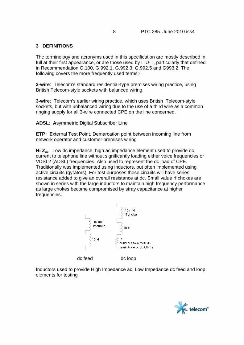
3 DEFINITIONS The terminology and acronyms used in this specification are mostly described in full at their first appearance, or are those used by ITU-T, particularly that defined in Recommendation G.100, G.992.1, G.992.3, G.992.5 and G993.2. The following covers the more frequently used terms:- 2-wire: Telecom’s standard residential-type premises wiring practice, using British Telecom-style sockets with balanced wiring. 3-wire: Telecom’s earlier wiring practice, which uses British Telecom-style sockets, but with unbalanced wiring due to the use of a third wire as a common ringing supply for all 3-wire connected CPE on the line concerned. ADSL: Asymmetric Digital Subscriber Line ETP: External Test Point. Demarcation point between incoming line from network operator and customer premises wiring Hi Zac: Low dc impedance, high ac impedance element used to provide dc current to telephone line without significantly loading either voice frequencies or VDSL2 (ADSL) frequencies. Also used to represent the dc load of CPE. Traditionally was implemented using inductors, but often implemented using active circuits (gyrators). For test purposes these circuits will have series resistance added to give an overall resistance at dc. Small value rf chokes are shown in series with the large inductors to maintain high frequency performance as large chokes become compromised by stray capacitance at higher frequencies.
dc feed dc loop Inductors used to provide High Impedance ac, Low Impedance dc feed and loop elements for testing
9 PTC 285 June 2010 iss4
IMP: Interference Management Plan Spectral Management plan for services which use Chorus Copper cable. Available on Commerce Commission website: http://www.comcom.govt.nz/IndustryRegulation/Telecommunications/StandardTermsDeterminations/UnbundledLocalLoopService/DecisionsList1.aspx POTS: Plain Old Telephone Service VDSL: Very high speed Digital Subscriber Line DSL technology utilizing frequencies up to 12 MHz. Compared with ADSL2+, the lower downstream band is extended to 3 MHz with additional bands using 3 - 5.1 MHz ( upstream 1), and 5.1 to 7.05 MHz (downstream 2) and 7.05 to 12 MHz (upstream 2).
• Reference: ITU-T Recommendation G993.1.
• The frequencies above are for bandplan 997, there are variations for other bandplans. VDSL2: Very high speed Digital Subscriber Line 2 Extension to VDSL utilizing frequencies up to 30 MHz. Additional bands use 12MHz to 14 MHz (downstream 3) and 14 MHz to 17.664 MHz (upstream 3) (997E17). The 30 MHz plan (997E30) extends US3 to 19.5 MHz and adds 19.5 MHz to 27 MHz (DS4) and 27 MHz to 30 MHz (US4).
• Reference: ITU-T Recommendation G993.2.
• Presently the use of Chorus Copper cable is limited by the New Zealand Interference Management plan to bandplan 997E17
• The frequencies above are for bandplan 997, there are variations for other bandplans.
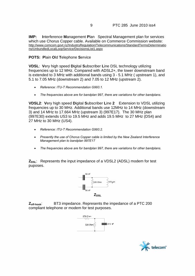
ZDSL: Represents the input impedance of a VDSL2 (ADSL) modem for test puposes.
100 Ohm 470 uH
56 nF
56 nF ZDSL
Zoff-hook: BT3 impedance. Represents the impedance of a PTC 200 compliant telephone or modem for test purposes.

10 PTC 285 June 2010 iss4
Zoff-hook (BT3) Zon-hook: Impedance represented by the ringers of 5 on-hook telephones in parallel with 10k leakage resistance for test purposes.
Zon-hook

11 PTC 285 June 2010 iss4
4 TELEPERMIT TECHNICAL REQUIREMENTS 4.1 Electrical Safety Splitters shall meet the requirements of AS/NZS 60950 4.2 EMC Splitters shall meet the requirements of AS/NZS CISPR22 4.3 DC Requirements 4.3.1 DC Loop Resistance: Not greater than 25 Ohms measured at the line port with the POTS CPE port short circuited. 4.3.2 Insulation Resistance: Not less than 10 MOhms between the legs of the line port with an applied voltage of +/- 200 Vdc and with the POTS CPE port open circuited. No loss of insulation resistance shall occur following the application of +/- 500 Vdc (current limited to 3 mA) for one minute.
• This allows for the non-destructive operation of overvoltage protection at the line port to allow lower voltage rated shunt components.
4.4 Ringing Frequency Requirements (ref ETSI TS 101 952-1-1 clause 6.3) 4.4.1 Ringer Loading (a) The Splitter shall not unduly effect the ringing of analogue CPE connected behind it. (b) Requirement
1. LRN shall be greater or equal to 4 2. RN shall be less than or equal to 1
(c) Test Method The splitter under test is connected into the test circuit shown in Figure 3.
1. Close switch Sw1, Open all switches SwA to SwJ. 2. Adjust Rp until V1 = 107 Vp-p 3. Open Switch Sw1 4. Close switches SwA to SwJ one by one until V2 falls below 107 Vp-p. 5. Re-open the last switch closed (the voltage will now be above or equal to
107 Vp-p) 6. Calculate LRN = (number of switches closed) / 2 7. Calculate RN = 5 - LRN 8. RN numbers of zero are rounded up to 0.5
12 PTC 285 June 2010 iss4
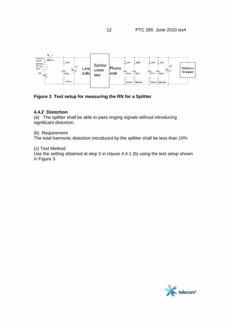
Figure 3 Test setup for measuring the RN for a Splitter 4.4.2 Distortion (a) The splitter shall be able to pass ringing signals without introducing significant distortion. (b) Requirement The total harmonic distortion introduced by the splitter shall be less than 10% (c) Test Method Use the setting obtained at step 5 in clause 4.4.1 (b) using the test setup shown in Figure 3.
13 PTC 285 June 2010 iss4
4.5 Voice Frequency Requirements 4.5.1 Insertion Loss (a) In order that Telephony speech levels are not unduly attenuated or
distorted by the deployment of splitters, the voice frequency losses and distortion shall be controlled.
(b) Requirements
(i) The insertion loss between the Line port and the POTS CPE port shall not exceed 1 dB at 1 kHz in either direction. The insertion loss shall be measured with a sinusoidal source of -12.2 dBV and + 1 dBV (see Figure 4)
(ii) The insertion loss shall not vary by more than +/- 1.0 dB from the
1 kHz value over the frequency band 200 Hz to 4000 Hz. (iii) The measurements in (i) and (ii) above shall be measured with a loop
current of 0, 20, 40 and 80 mA
• The measurement at zero loop current is to ensure that on-hook data transmission used for caller ID will not be adversely affected.
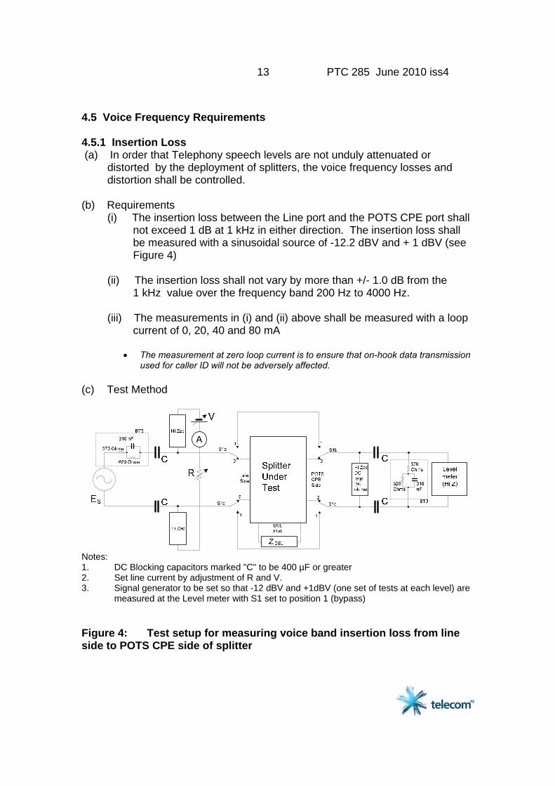
(c) Test Method
Notes: 1. DC Blocking capacitors marked "C" to be 400 µF or greater 2. Set line current by adjustment of R and V. 3. Signal generator to be set so that -12 dBV and +1dBV (one set of tests at each level) are measured at the Level meter with S1 set to position 1 (bypass) Figure 4: Test setup for measuring voice band insertion loss from line side to POTS CPE side of splitter
14 PTC 285 June 2010 iss4
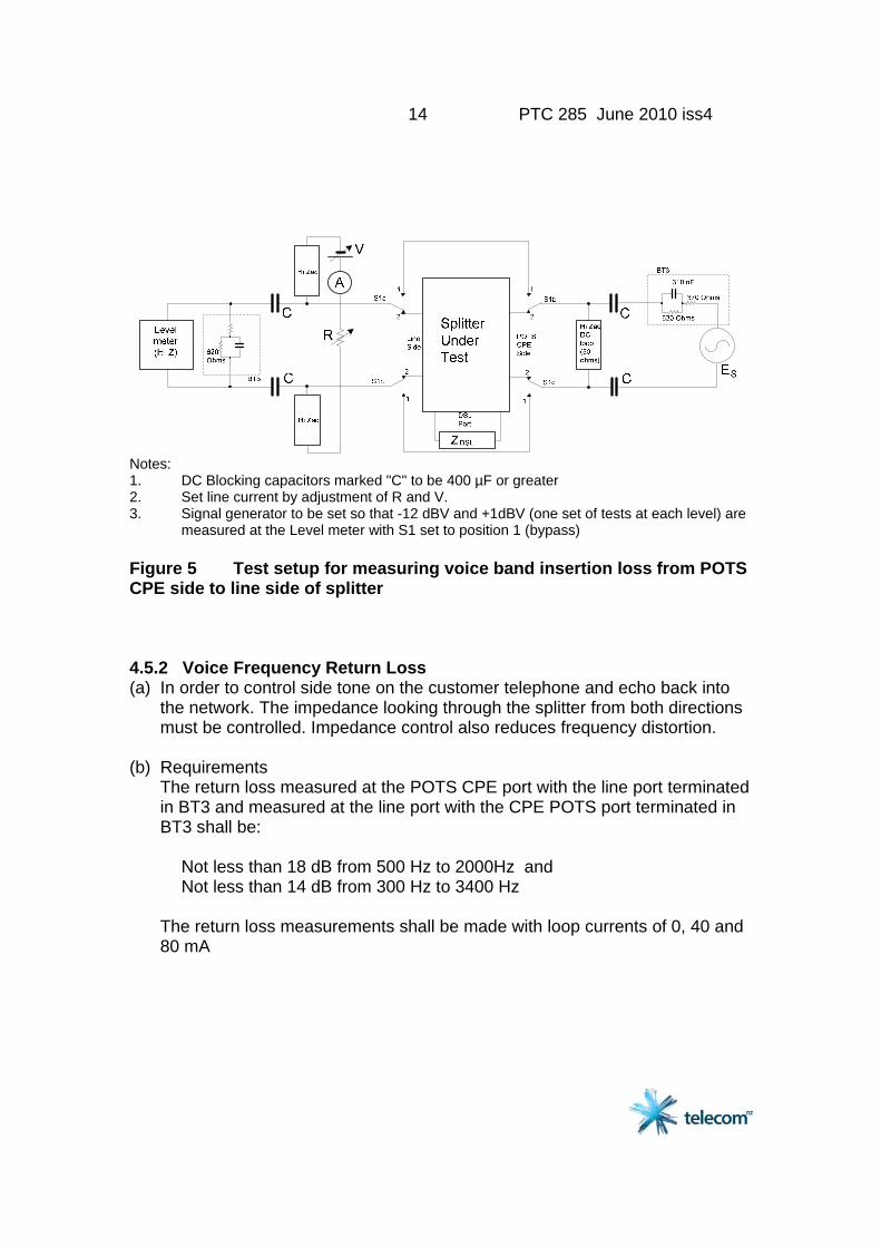
Notes: 1. DC Blocking capacitors marked "C" to be 400 µF or greater 2. Set line current by adjustment of R and V. 3. Signal generator to be set so that -12 dBV and +1dBV (one set of tests at each level) are measured at the Level meter with S1 set to position 1 (bypass) Figure 5 Test setup for measuring voice band insertion loss from POTS CPE side to line side of splitter 4.5.2 Voice Frequency Return Loss (a) In order to control side tone on the customer telephone and echo back into
the network. The impedance looking through the splitter from both directions must be controlled. Impedance control also reduces frequency distortion.
(b) Requirements The return loss measured at the POTS CPE port with the line port terminated
in BT3 and measured at the line port with the CPE POTS port terminated in BT3 shall be:
Not less than 18 dB from 500 Hz to 2000Hz and Not less than 14 dB from 300 Hz to 3400 Hz The return loss measurements shall be made with loop currents of 0, 40 and
80 mA

15 PTC 285 June 2010 iss4
(c) Test Method
Notes: 1. DC Blocking capacitors marked "C" to be 400 µF or greater 2. Set line current by adjustment of R and V. Figure 6 Test setup for measuring return loss at line side of splitter
SplitterUnderTest
LineSide
POTSCPESide
Hi ZacDCloop(50ohms)
Hi Zac
Hi Zac
R
DSLPort
ZDSL
C
C
C
C
V
BT3
ImpedancemeasuringInstrument
A
Notes: 1. DC Blocking capacitors marked "C" to be 400 µF or greater 2. Set line current by adjustment of R and V.
16 PTC 285 June 2010 iss4
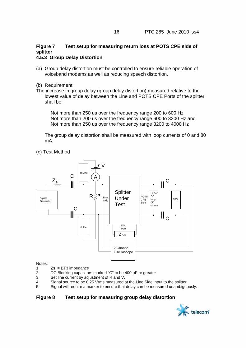
Figure 7 Test setup for measuring return loss at POTS CPE side of splitter 4.5.3 Group Delay Distortion (a) Group delay distortion must be controlled to ensure reliable operation of
voiceband modems as well as reducing speech distortion. (b) Requirement The increase in group delay (group delay distortion) measured relative to the
lowest value of delay between the Line and POTS CPE Ports of the splitter shall be:
Not more than 250 us over the frequency range 200 to 600 Hz Not more than 200 us over the frequency range 600 to 3200 Hz and Not more than 250 us over the frequency range 3200 to 4000 Hz The group delay distortion shall be measured with loop currents of 0 and 80
mA. (c) Test Method
SplitterUnderTest
LineSide
POTSCPESide
Hi Zac
Hi Zac
R
DSLPort
ZDSL
C
C
C
C
V
SignalGenerator
2 ChannelOscilloscope
Z s
Hi ZacDCloop(50ohms)
BT3
A
Notes: 1. Zs = BT3 impedance 2. DC Blocking capacitors marked "C" to be 400 µF or greater 3. Set line current by adjustment of R and V. 4. Signal source to be 0.25 Vrms measured at the Line Side input to the splitter 5. Signal will require a marker to ensure that delay can be measured unambiguously. Figure 8 Test setup for measuring group delay distortion
17 PTC 285 June 2010 iss4
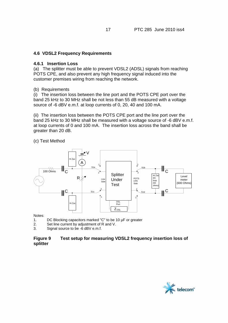
4.6 VDSL2 Frequency Requirements 4.6.1 Insertion Loss (a) The splitter must be able to prevent VDSL2 (ADSL) signals from reaching POTS CPE, and also prevent any high frequency signal induced into the customer premises wiring from reaching the network. (b) Requirements (i) The insertion loss between the line port and the POTS CPE port over the band 25 kHz to 30 MHz shall be not less than 55 dB measured with a voltage source of -6 dBV e.m.f. at loop currents of 0, 20, 40 and 100 mA. (ii) The insertion loss between the POTS CPE port and the line port over the band 25 kHz to 30 MHz shall be measured with a voltage source of -6 dBV e.m.f. at loop currents of 0 and 100 mA. The insertion loss across the band shall be greater than 20 dB. (c) Test Method
Hi Zac
Hi Zac
R
100 Ohms
V
C
C
A
Hi ZacDCloop(50ohms)
Levelmeter
(600 Ohms)
C
C
SplitterUnderTest
LineSide
DSLPort
ZDSL
POTSCPESide
S1a1
2
S1b
S1c
1
2S1d
1
2
1
2
Notes: 1. DC Blocking capacitors marked "C" to be 10 µF or greater 2. Set line current by adjustment of R and V. 3. Signal source to be -6 dBV e.m.f. Figure 9 Test setup for measuring VDSL2 frequency insertion loss of splitter
18 PTC 285 June 2010 iss4
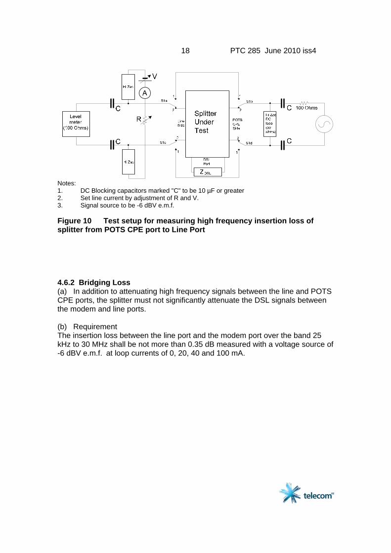
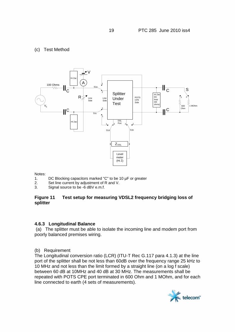
Notes: 1. DC Blocking capacitors marked "C" to be 10 µF or greater 2. Set line current by adjustment of R and V. 3. Signal source to be -6 dBV e.m.f. Figure 10 Test setup for measuring high frequency insertion loss of splitter from POTS CPE port to Line Port 4.6.2 Bridging Loss (a) In addition to attenuating high frequency signals between the line and POTS CPE ports, the splitter must not significantly attenuate the DSL signals between the modem and line ports. (b) Requirement The insertion loss between the line port and the modem port over the band 25 kHz to 30 MHz shall be not more than 0.35 dB measured with a voltage source of -6 dBV e.m.f. at loop currents of 0, 20, 40 and 100 mA.
19 PTC 285 June 2010 iss4
(c) Test Method
LineSide
Hi Zac
Hi Zac
R
100 Ohms
V
C
CVs
A
SplitterUnderTest
LineSide
POTSCPESide
S1a1
2
S1b
S1c1
2
S1d
1 2 12
Hi ZacDCloop(50ohms)
C
C600Ohm
1 MOhm
S
1 2
DSLPort
ZDSL
Levelmeter(Hi Z)
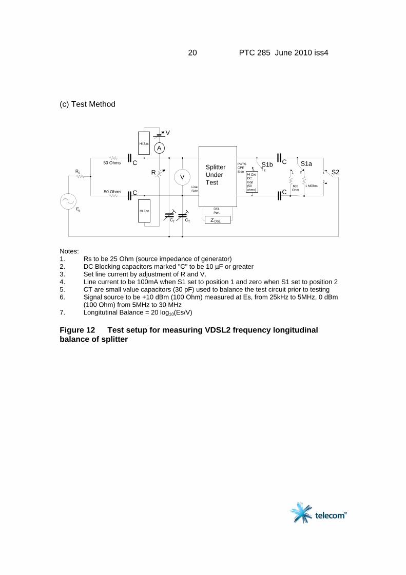
Notes: 1. DC Blocking capacitors marked "C" to be 10 µF or greater 2. Set line current by adjustment of R and V. 3. Signal source to be -6 dBV e.m.f. Figure 11 Test setup for measuring VDSL2 frequency bridging loss of splitter 4.6.3 Longitudinal Balance (a) The splitter must be able to isolate the incoming line and modem port from poorly balanced premises wiring. (b) Requirement The Longitudinal conversion ratio (LCR) (ITU-T Rec G.117 para 4.1.3) at the line port of the splitter shall be not less than 60dB over the frequency range 25 kHz to 10 MHz and not less than the limit formed by a straight line (on a log f scale) between 60 dB at 10MHz and 40 dB at 30 MHz. The measurements shall be repeated with POTS CPE port terminated in 600 Ohm and 1 MOhm, and for each line connected to earth (4 sets of measurements).
20 PTC 285 June 2010 iss4
(c) Test Method
SplitterUnderTest
LineSide
POTSCPESide
Hi ZacDCloop(50ohms)
Hi Zac
Hi Zac
R
DSLPort
ZDSL
50 Ohms
V
C
C
C
C
Es
600Ohm
1 MOhm
1 2Rs
50 Ohms
V
CT CT
S1aS21
2
A
21S1b
Notes: 1. Rs to be 25 Ohm (source impedance of generator) 2. DC Blocking capacitors marked "C" to be 10 µF or greater 3. Set line current by adjustment of R and V. 4. Line current to be 100mA when S1 set to position 1 and zero when S1 set to position 2 5. CT are small value capacitors (30 pF) used to balance the test circuit prior to testing 6. Signal source to be +10 dBm (100 Ohm) measured at Es, from 25kHz to 5MHz, 0 dBm (100 Ohm) from 5MHz to 30 MHz 7. Longitutinal Balance = 20 log10(Es/V) Figure 12 Test setup for measuring VDSL2 frequency longitudinal balance of splitter
21 PTC 285 June 2010 iss4
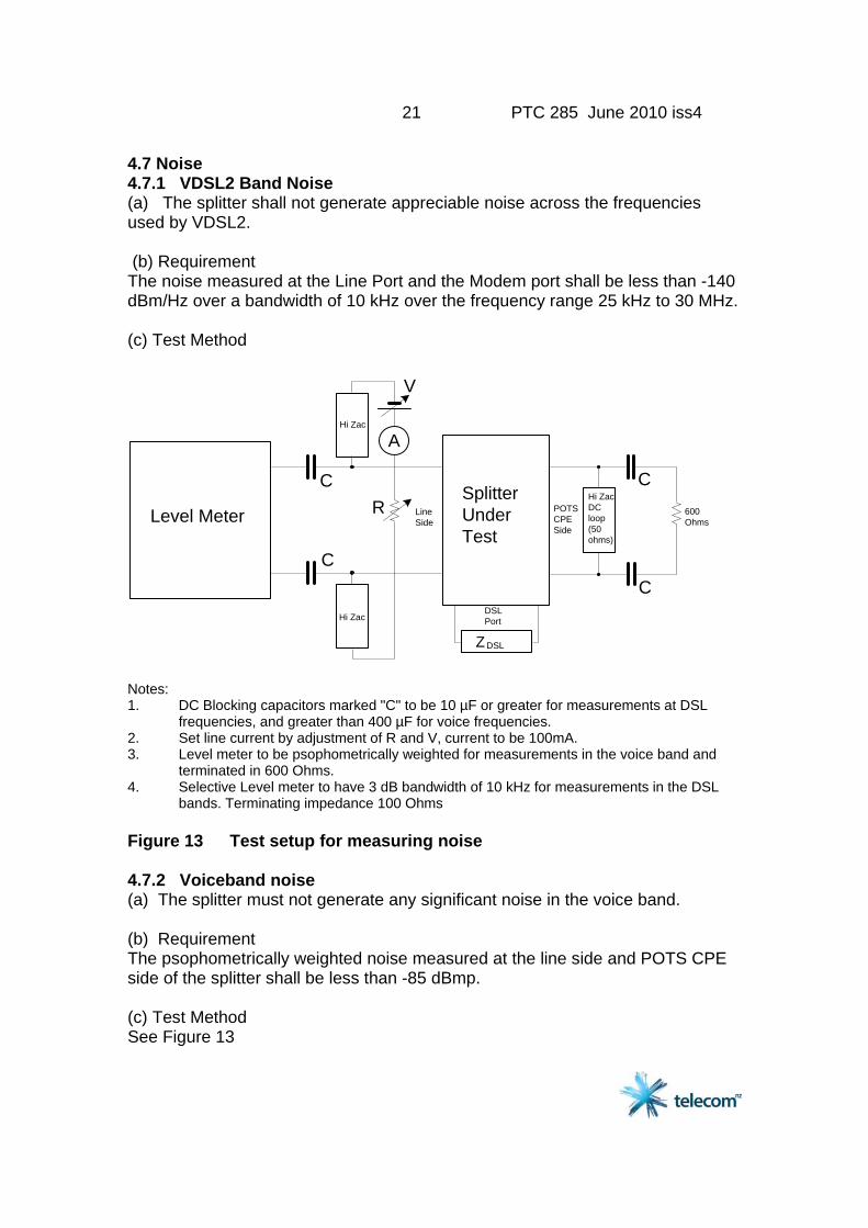
4.7 Noise 4.7.1 VDSL2 Band Noise (a) The splitter shall not generate appreciable noise across the frequencies used by VDSL2. (b) Requirement The noise measured at the Line Port and the Modem port shall be less than -140 dBm/Hz over a bandwidth of 10 kHz over the frequency range 25 kHz to 30 MHz. (c) Test Method
600Ohms
SplitterUnderTest
LineSide
POTSCPESide
Hi ZacDCloop(50ohms)
Hi Zac
Hi Zac
R
DSLPort
ZDSL
V
C
C
C
C
Level Meter
A
Notes: 1. DC Blocking capacitors marked "C" to be 10 µF or greater for measurements at DSL frequencies, and greater than 400 µF for voice frequencies. 2. Set line current by adjustment of R and V, current to be 100mA. 3. Level meter to be psophometrically weighted for measurements in the voice band and terminated in 600 Ohms. 4. Selective Level meter to have 3 dB bandwidth of 10 kHz for measurements in the DSL bands. Terminating impedance 100 Ohms Figure 13 Test setup for measuring noise 4.7.2 Voiceband noise (a) The splitter must not generate any significant noise in the voice band. (b) Requirement The psophometrically weighted noise measured at the line side and POTS CPE side of the splitter shall be less than -85 dBmp. (c) Test Method See Figure 13
22 PTC 285 June 2010 iss4
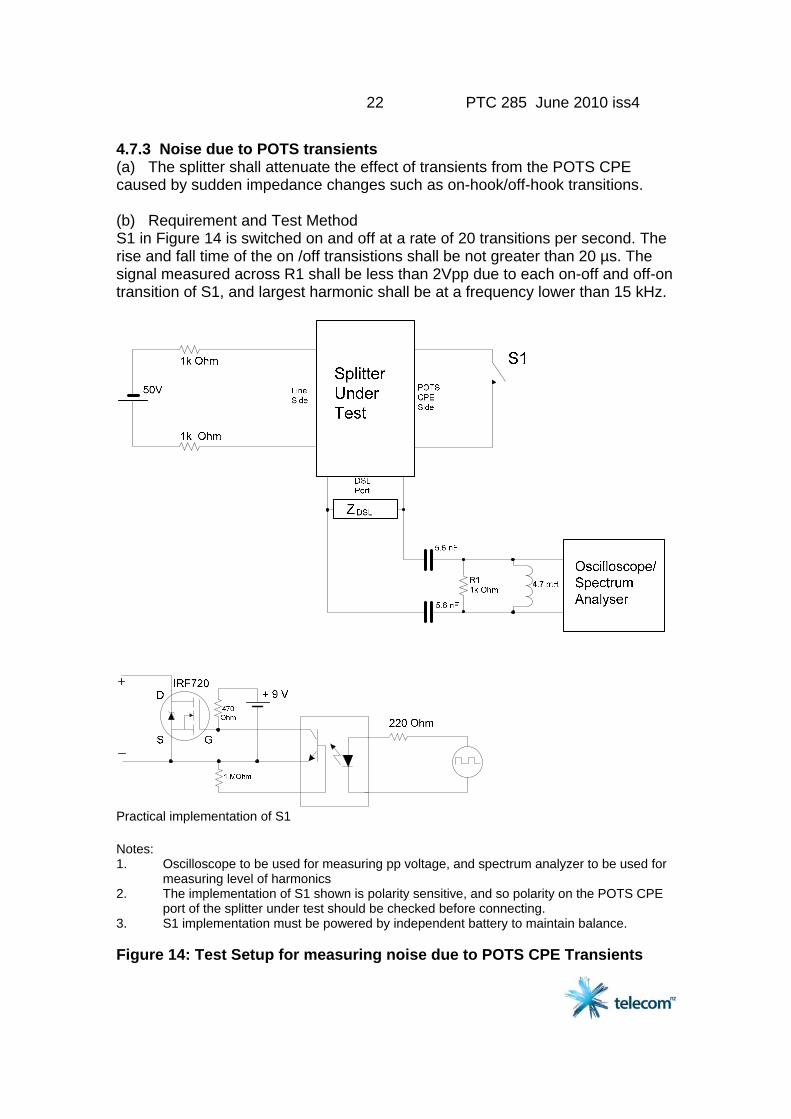
4.7.3 Noise due to POTS transients (a) The splitter shall attenuate the effect of transients from the POTS CPE caused by sudden impedance changes such as on-hook/off-hook transitions. (b) Requirement and Test Method S1 in Figure 14 is switched on and off at a rate of 20 transitions per second. The rise and fall time of the on /off transistions shall be not greater than 20 µs. The signal measured across R1 shall be less than 2Vpp due to each on-off and off-on transition of S1, and largest harmonic shall be at a frequency lower than 15 kHz.
Practical implementation of S1 Notes: 1. Oscilloscope to be used for measuring pp voltage, and spectrum analyzer to be used for measuring level of harmonics 2. The implementation of S1 shown is polarity sensitive, and so polarity on the POTS CPE port of the splitter under test should be checked before connecting. 3. S1 implementation must be powered by independent battery to maintain balance. Figure 14: Test Setup for measuring noise due to POTS CPE Transients
23 PTC 285 June 2010 iss4
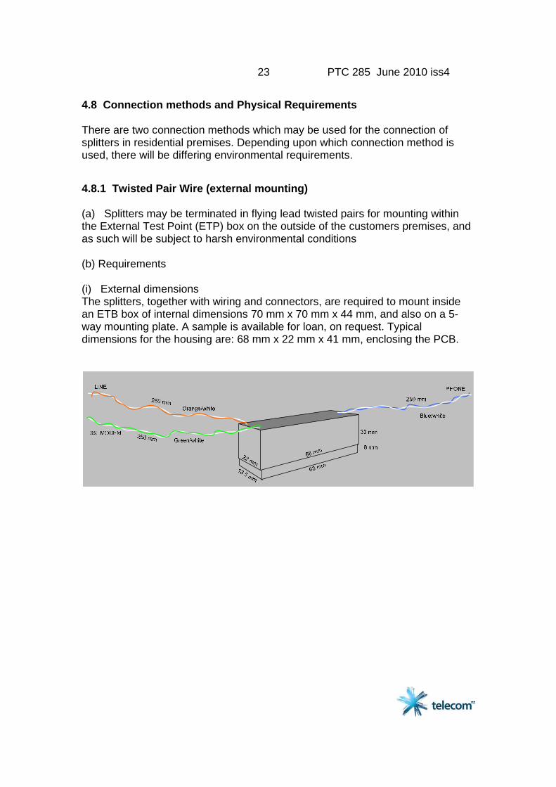
4.8 Connection methods and Physical Requirements There are two connection methods which may be used for the connection of splitters in residential premises. Depending upon which connection method is used, there will be differing environmental requirements. 4.8.1 Twisted Pair Wire (external mounting) (a) Splitters may be terminated in flying lead twisted pairs for mounting within the External Test Point (ETP) box on the outside of the customers premises, and as such will be subject to harsh environmental conditions (b) Requirements (i) External dimensions The splitters, together with wiring and connectors, are required to mount inside an ETB box of internal dimensions 70 mm x 70 mm x 44 mm, and also on a 5-way mounting plate. A sample is available for loan, on request. Typical dimensions for the housing are: 68 mm x 22 mm x 41 mm, enclosing the PCB.

24 PTC 285 June 2010 iss4
33 mm
8 mm
2.5 mm
63 mm
2.5 mm 3 mm
18 mm
8 mm
33 mm
3 mm
18 mm
Figure 15: External Dimensions of a splitter (ii) Connection leads The LINE port connects to an insulated orange/white twisted pair of wires having 0.5 mm diameter conductors. The TELE port and DSL modem port connects to an insulated blue/white pair and green/white pair respectively of similar wires. The LINE port and DSL modem port pairs shall emerge from the encapsulation at one end and the PHONE port from the other end. Insulation shall be compatible with the encapsulating material. The leads are each 250 mm long outside the assembly. The splitter or its package shall be marked: “orange/white pr to LINE wiring, blue/white pr to PHONE wiring. green/white pr to DSL Modem wiring” (iii) Environmental The splitter shall reliably operate over a temperature range of -10ºC to 70ºC and when submerged in water to a maximum depth of 45 mm. Full encapsulation to IP07, that does not affect the electrical components, their characteristics or reliability, is required. The lead wires, but not their external terminations, are included. The following HAST-test shall be included to qualify effective encapsulation: A current limited 100 Vdc supply is applied to the LINE port for 100 hours, with the splitter exposed to 110ºC / 85%RH and over-pressure of 0.24 kg/cm² (23.5 kPa.) Insulation shall not have failed following this test.
25 PTC 285 June 2010 iss4
4.8.1 Twisted Pair Wire (internal mounting) (a) Splitters may be terminated in flying lead twisted pairs for mounting inside the customers premises. These may be mounted in a home distributor cabinet or a service delivery point enclosure. (b) Requirements (i) External dimensions The dimensions of the splitter for internal use are not critical and may be designed to meet the requirements of specific home distributor cabinets etc. In lieu of any specific requirements, dimensions similar to those for the external splitter would be appropriate for general use. (ii) Connection leads The LINE port connects to an insulated orange/white twisted pair of wires having 0.5 mm diameter conductors. The TELE port and DSL modem port connects to an insulated blue/white pair and green/white pair respectively of similar wires. The LINE port and DSL modem port pairs shall emerge from the encapsulation at one end and the PHONE port from the other end. Insulation shall be compatible with the encapsulating material. The leads are each 250 mm long outside the assembly. The splitter or its package shall be marked: “orange/white pr to LINE wiring, blue/white pr to PHONE wiring. green/white pr to DSL Modem wiring” (iii) Environmental The splitter should be designed to meet the requirements of the environment for which it is intended. In general, it would be expected that a temperature range of 0 - 40ºC with RH up to 90% would be appropriate. Suppliers should state the environment parameters which the splitter is suitable for. 4.8.3 Plug and socket connection (a) Connection using plug and socket enables simple customer self-install, and has the advantage that the same method can be used to connect a residential gateway. The point in the customer premises where the splitter is connected is known as the Disconnect Test Point (DTP). This may be in a Star Wiring Distribution Cabinet (Ref: PTC106) or a standalone device (PTC227). There are a number of options for the terminations on the splitter itself, as the cables between the splitter and the DTP may accommodate different arrangements at the splitter end, as long as they are compatible with the DTP.
26 PTC 285 June 2010 iss4
ADSLMODEM
Cat 5 cable terminatedwith RJ45 plugs
IDC connnector
RJ45Socket
To ETP
To securitysystem
Screw Terminal
Fit Links if securitysystem not installed
1 8 1 8
DTP1sa
To otherjackpoints
BTSocket
EXT INT
SPLITTER
LPF (splitter function)
RJ12
RJ45HPF
RJ45 or RJ12POTS CPE Port
Line Port
DSL Modem Port
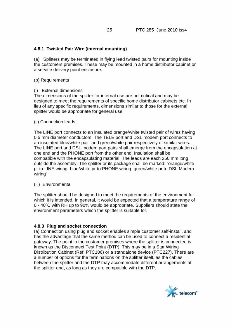
Figure 16: Connection of DSL Splitter at DTP using single cable As the DTP has internal connections between the two sockets, one cable may connect both the LINE connection and the POTS CPE connection between the splitter and DTP. The modem is then plugged into the DSL port on the splitter. This is shown in Figure 16. While a socket is required for the DSL modem port, the LINE port and the CPE POTS port can be permanently wired to a short length of cable terminated in an RJ45 plug. It is recommended that while the Line port has terminations for both the Line and the POTS CPE ports of the splitter, connection to the POTS CPE port is also possible for situations where Disconnect Test Points have been implemented differently. Figure 17 shows all three ports of the splitter terminated by sockets.
27 PTC 285 June 2010 iss4
ADSLMODEM
Cat 5 cable terminatedwith RJ45 plugs
IDC connnector
RJ45Socket
To ETP
To securitysystem
Screw Terminal
Fit Links if securitysystem not installed
1 8 1 8
DTP1sa
To otherjackpoints
BTSocket
EXT INT
SPLITTER
LPF (splitter function)
RJ12
RJ45HPF
RJ45 or RJ12CPE POTS Port
Line Port
DSL Modem Port
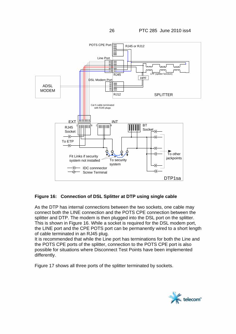
Figure 17 Connection of DSL Splitter at DTP using two cables
28 PTC 285 June 2010 iss4
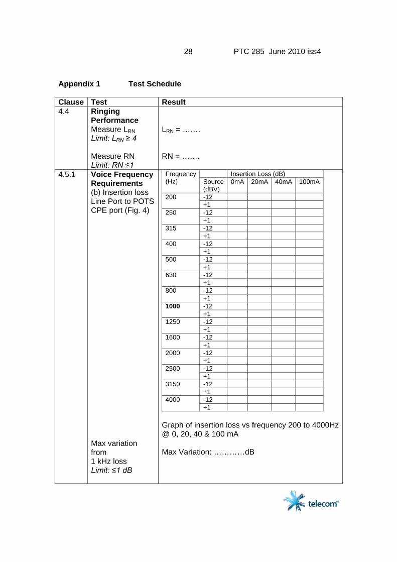
Appendix 1 Test Schedule Clause Test Result 4.4 Ringing
Performance Measure LRN Limit: LRN ≥ 4 Measure RN Limit: RN ≤1
LRN = ……. RN = …….
4.5.1
Voice Frequency Requirements (b) Insertion loss Line Port to POTS CPE port (Fig. 4) Max variation from 1 kHz loss Limit: ≤1 dB
Insertion Loss (dB) Frequency (Hz) Source
(dBV) 0mA 20mA 40mA 100mA
-12 200 +1 -12 250 +1 -12 315 +1 -12 400 +1 -12 500 +1 -12 630 +1 -12 800 +1 -12 1000 +1 -12 1250 +1 -12 1600 +1 -12 2000 +1 -12 2500 +1 -12 3150 +1 -12 4000 +1
Graph of insertion loss vs frequency 200 to 4000Hz @ 0, 20, 40 & 100 mA Max Variation: …………dB
29 PTC 285 June 2010 iss4
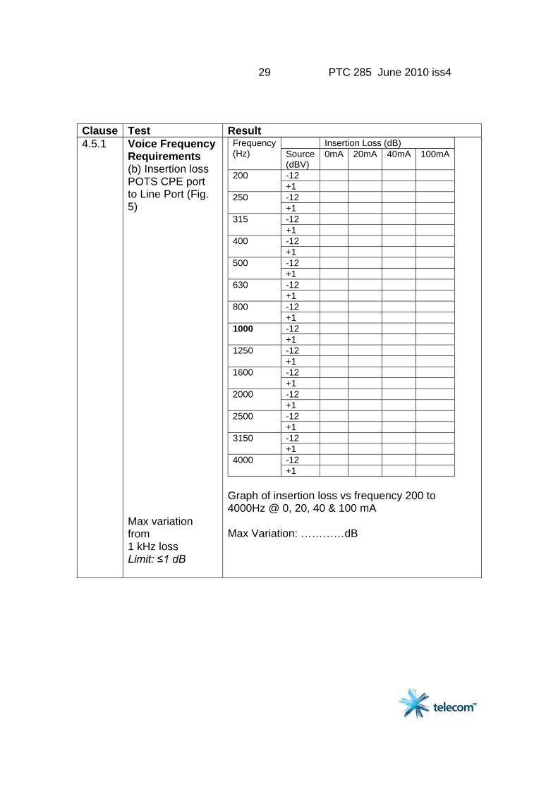
Clause Test Result 4.5.1
Voice Frequency Requirements (b) Insertion loss POTS CPE port to Line Port (Fig. 5) Max variation from 1 kHz loss Limit: ≤1 dB
Insertion Loss (dB) Frequency (Hz) Source
(dBV) 0mA 20mA 40mA 100mA
-12 200 +1 -12 250 +1 -12 315 +1 -12 400 +1 -12 500 +1 -12 630 +1 -12 800 +1 -12 1000 +1 -12 1250 +1 -12 1600 +1 -12 2000 +1 -12 2500 +1 -12 3150 +1 -12 4000 +1
Graph of insertion loss vs frequency 200 to 4000Hz @ 0, 20, 40 & 100 mA Max Variation: …………dB
30 PTC 285 June 2010 iss4
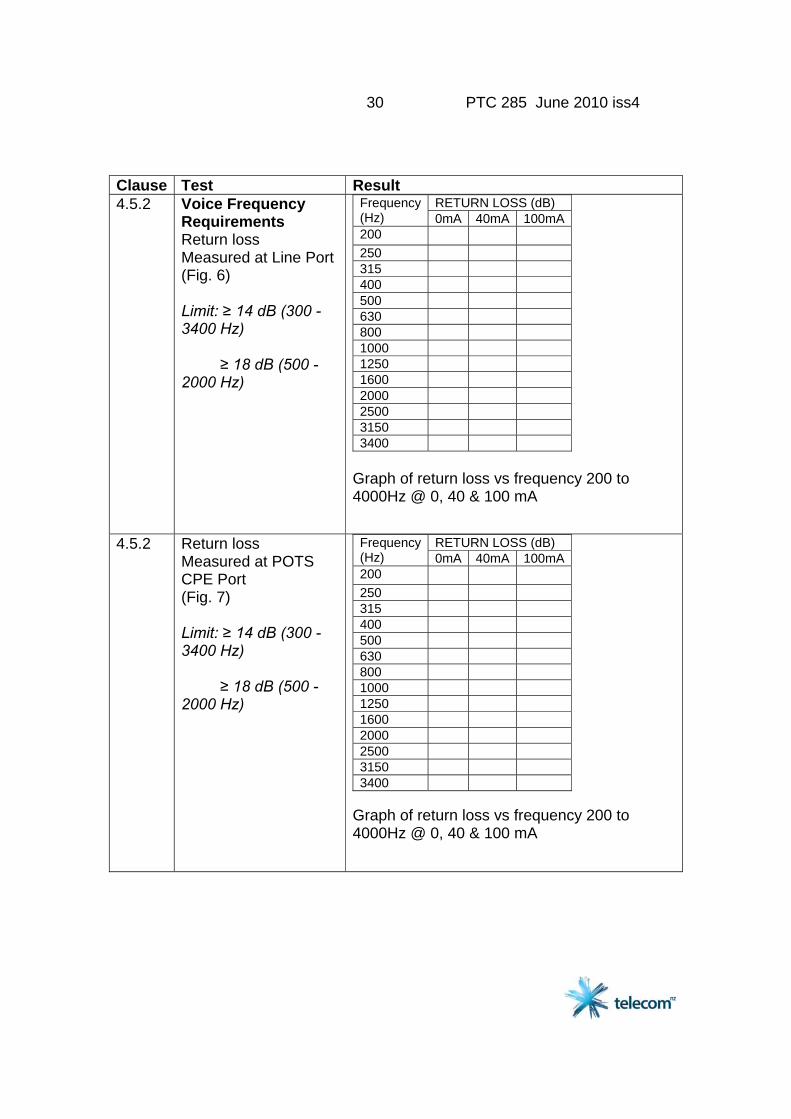
Clause Test Result 4.5.2
Voice Frequency Requirements Return loss Measured at Line Port (Fig. 6) Limit: ≥ 14 dB (300 - 3400 Hz) ≥ 18 dB (500 - 2000 Hz)
RETURN LOSS (dB) Frequency (Hz) 0mA 40mA 100mA 200 250 315 400 500 630 800 1000 1250 1600 2000 2500 3150 3400
Graph of return loss vs frequency 200 to 4000Hz @ 0, 40 & 100 mA
4.5.2
Return loss Measured at POTS CPE Port (Fig. 7) Limit: ≥ 14 dB (300 - 3400 Hz) ≥ 18 dB (500 - 2000 Hz)
RETURN LOSS (dB) Frequency (Hz) 0mA 40mA 100mA 200 250 315 400 500 630 800 1000 1250 1600 2000 2500 3150 3400
Graph of return loss vs frequency 200 to 4000Hz @ 0, 40 & 100 mA
31 PTC 285 June 2010 iss4
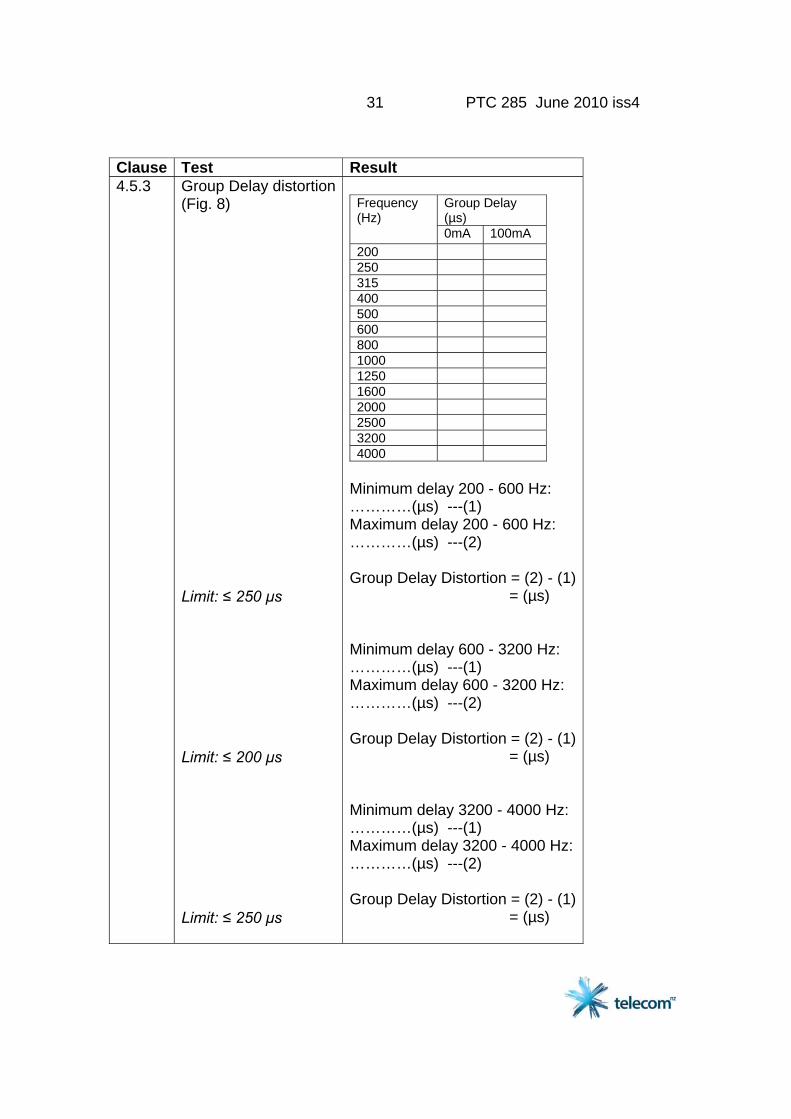
Clause Test Result 4.5.3
Group Delay distortion(Fig. 8) Limit: ≤ 250 µs Limit: ≤ 200 µs Limit: ≤ 250 µs
Group Delay (µs)
Frequency (Hz)
0mA 100mA 200 250 315 400 500 600 800 1000 1250 1600 2000 2500 3200 4000
Minimum delay 200 - 600 Hz: …………(µs) ---(1) Maximum delay 200 - 600 Hz: …………(µs) ---(2) Group Delay Distortion = (2) - (1) = (µs) Minimum delay 600 - 3200 Hz: …………(µs) ---(1) Maximum delay 600 - 3200 Hz: …………(µs) ---(2) Group Delay Distortion = (2) - (1) = (µs) Minimum delay 3200 - 4000 Hz: …………(µs) ---(1) Maximum delay 3200 - 4000 Hz: …………(µs) ---(2) Group Delay Distortion = (2) - (1) = (µs)
32 PTC 285 June 2010 iss4
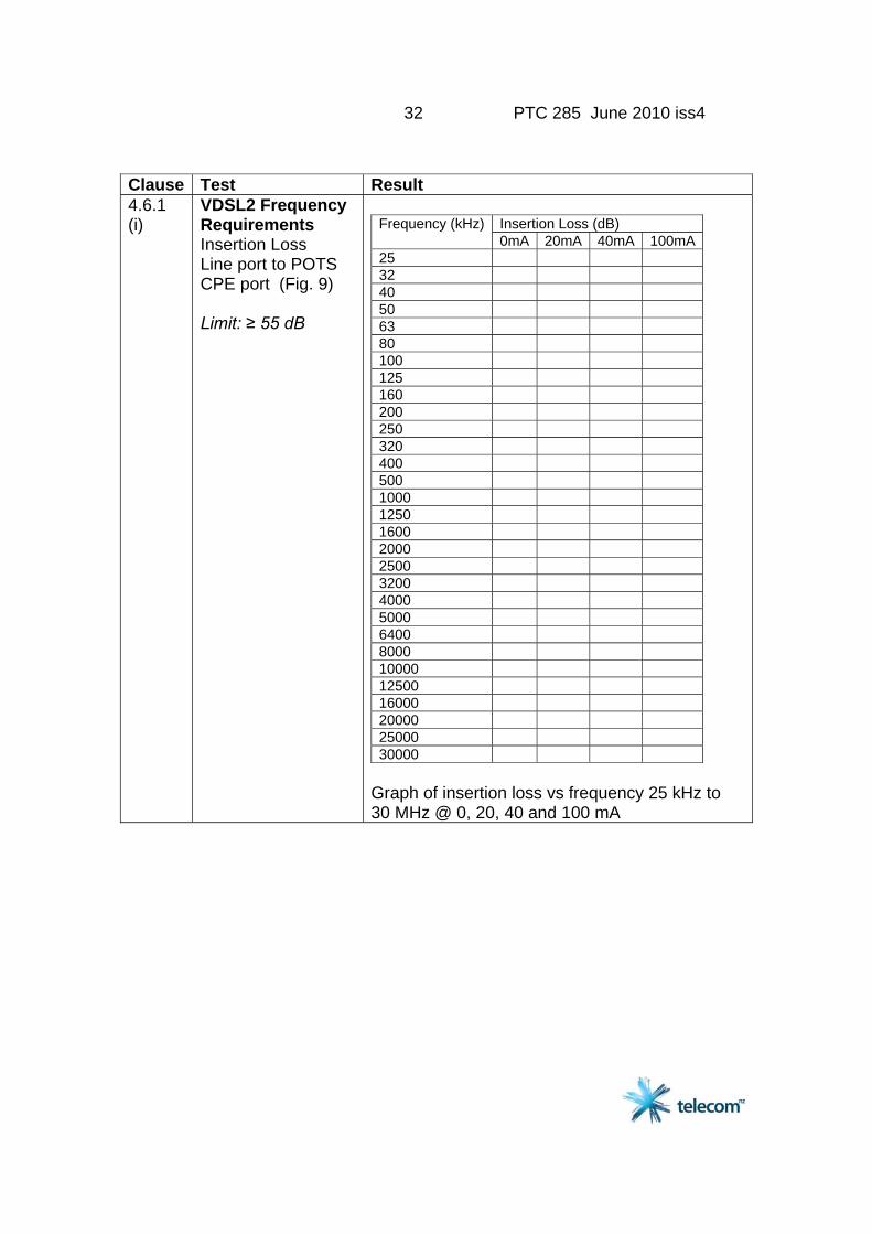
Clause Test Result 4.6.1 (i)
VDSL2 Frequency Requirements Insertion Loss Line port to POTS CPE port (Fig. 9) Limit: ≥ 55 dB
Insertion Loss (dB) Frequency (kHz)0mA 20mA 40mA 100mA
25 32 40 50 63 80 100 125 160 200 250 320 400 500 1000 1250 1600 2000 2500 3200 4000 5000 6400 8000 10000 12500 16000 20000 25000 30000
Graph of insertion loss vs frequency 25 kHz to 30 MHz @ 0, 20, 40 and 100 mA
33 PTC 285 June 2010 iss4
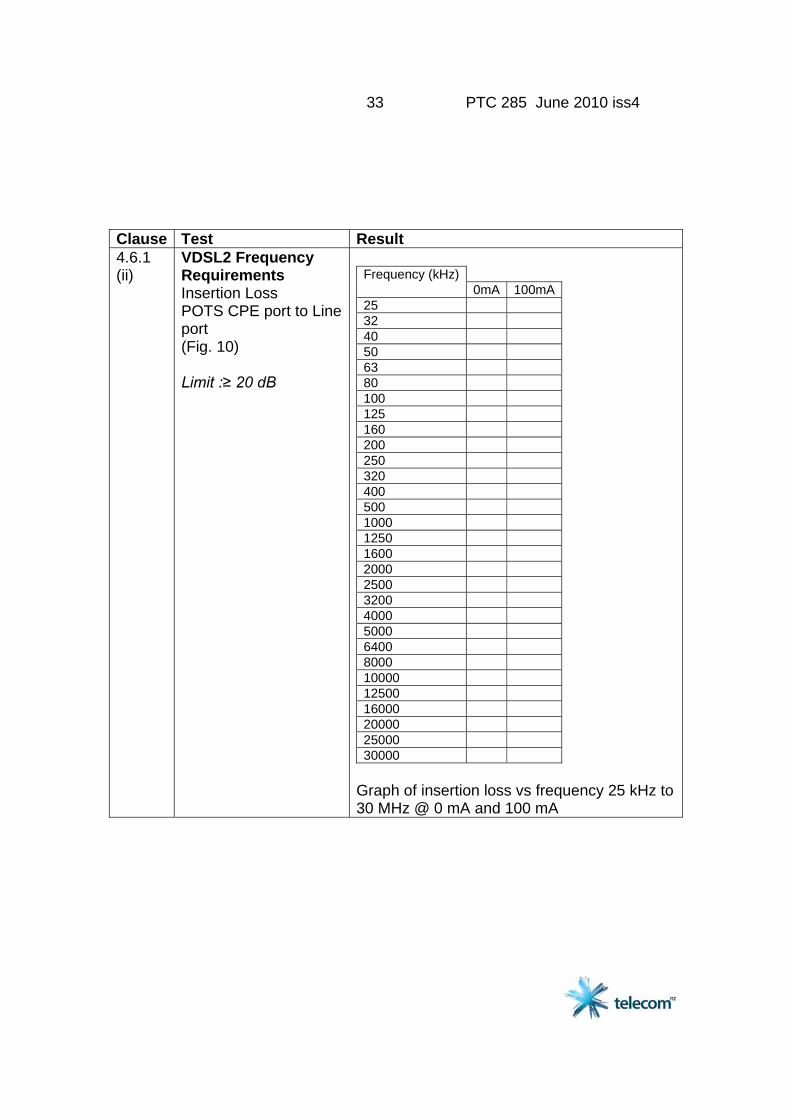
Clause Test Result 4.6.1 (ii)
VDSL2 Frequency Requirements Insertion Loss POTS CPE port to Line port (Fig. 10) Limit :≥ 20 dB
Frequency (kHz)
0mA 100mA25 32 40 50 63 80 100 125 160 200 250 320 400 500 1000 1250 1600 2000 2500 3200 4000 5000 6400 8000 10000 12500 16000 20000 25000 30000
Graph of insertion loss vs frequency 25 kHz to 30 MHz @ 0 mA and 100 mA
34 PTC 285 June 2010 iss4
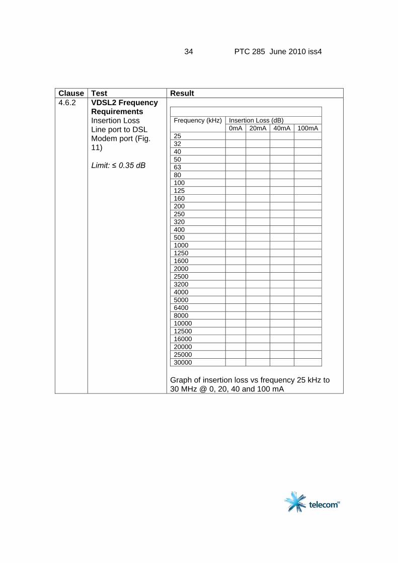
Clause Test Result 4.6.2
VDSL2 Frequency Requirements Insertion Loss Line port to DSL Modem port (Fig. 11) Limit: ≤ 0.35 dB
Insertion Loss (dB) Frequency (kHz)0mA 20mA 40mA 100mA
25 32 40 50 63 80 100 125 160 200 250 320 400 500 1000 1250 1600 2000 2500 3200 4000 5000 6400 8000 10000 12500 16000 20000 25000 30000
Graph of insertion loss vs frequency 25 kHz to 30 MHz @ 0, 20, 40 and 100 mA
35 PTC 285 June 2010 iss4
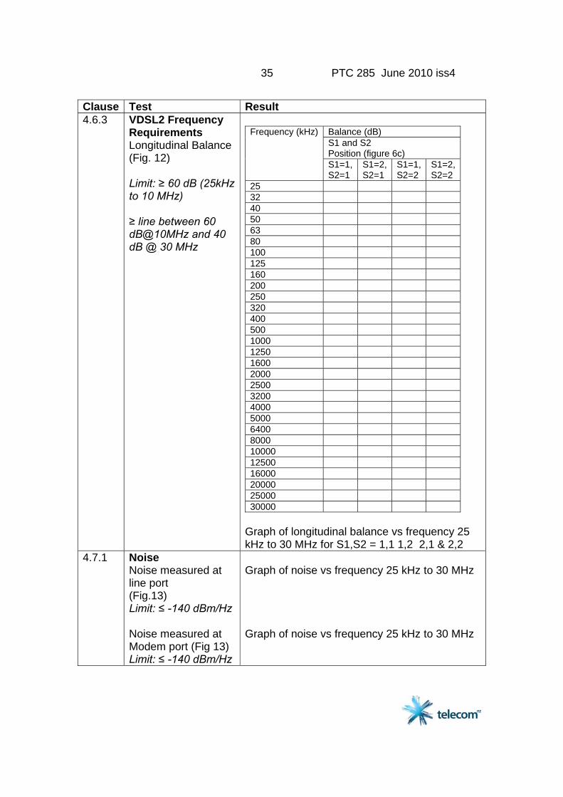
Clause Test Result 4.6.3
VDSL2 Frequency Requirements Longitudinal Balance (Fig. 12) Limit: ≥ 60 dB (25kHz to 10 MHz) ≥ line between 60 dB@10MHz and 40 dB @ 30 MHz
Balance (dB) S1 and S2 Position (figure 6c)
Frequency (kHz)
S1=1,S2=1
S1=2,S2=1
S1=1, S2=2
S1=2, S2=2
25 32 40 50 63 80 100 125 160 200 250 320 400 500 1000 1250 1600 2000 2500 3200 4000 5000 6400 8000 10000 12500 16000 20000 25000 30000
Graph of longitudinal balance vs frequency 25 kHz to 30 MHz for S1,S2 = 1,1 1,2 2,1 & 2,2
4.7.1 Noise Noise measured at line port (Fig.13) Limit: ≤ -140 dBm/Hz Noise measured at Modem port (Fig 13) Limit: ≤ -140 dBm/Hz
Graph of noise vs frequency 25 kHz to 30 MHz Graph of noise vs frequency 25 kHz to 30 MHz
36 PTC 285 June 2010 iss4
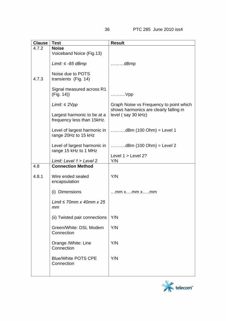
Clause Test Result 4.7.2 4.7.3
Noise Voiceband Noice (Fig.13) Limit: ≤ -85 dBmp Noise due to POTS transients (Fig. 14) Signal measured across R1 (Fig. 14)) Limit: ≤ 2Vpp Largest harmonic to be at a frequency less than 15kHz. Level of largest harmonic in range 20Hz to 15 kHz Level of largest harmonic in range 15 kHz to 1 MHz Limit: Level 1 > Level 2
………dBmp ……….Vpp Graph Noise vs Frequency to point which shows harmonics are clearly falling in level ( say 30 kHz) ……….dBm (100 Ohm) = Level 1 ……….dBm (100 Ohm) = Level 2 Level 1 > Level 2? Y/N
4.8 4.8.1
Connection Method Wire ended sealed encapsulation (i) Dimensions Limit ≤ 70mm x 40mm x 25 mm (ii) Twisted pair connections Green/White: DSL Modem Connection Orange /White: Line Connection Blue/White POTS CPE Connection
Y/N …mm x….mm x…..mm Y/N Y/N Y/N Y/N

37 PTC 285 June 2010 iss4
Clause Test Result 4.8.1 Cont. 4.8.2
(iii) Environmental Test Additional test report Photographs Wire ended unsealed encapsulation (i) Dimensions (ii) Twisted pair connections Green/White: DSL Modem Connection Orange /White: Line Connection Blue/White POTS CPE Connection (iii) Environmental Limits (manufacturer's statement) Temperature range: Min: Max: Relative Humidity Range: Min: Max:
Y/N Y/N Y/N …mm x….mm x…..mm Y/N Y/N Y/N Y/N ……Degrees Celsius ……Degrees Celsius ……..%RH ……..%RH Photographs
4.8.3 Plug and Socket Connection LINE port Plug Pinout
Description 1….. 2….. 3….. 4….. 5….. 6….. 7….. 8…..
38 PTC 285 June 2010 iss4
Clause Test Result 4.8.3 cont
CPE POTS port LINE port Plug Pinout Modem port Plug Pinout Photographs Internal and external
Description 1….. 2….. 3….. 4….. 5….. 6….. 7….. 8….. Description 1….. 2….. 3….. 4….. 5….. 6….. 7….. 8….. Photographs


![Index [cds.cern.ch]...Index 803 electrochemical properties, 287 five-level model, 285, 286 ISA, 286 nonlinear absorption, 285 photophysical properties, 285–287 solubility, 285 structure,](https://static.fdocuments.in/doc/165x107/6064d77b5ba3771e9668db51/index-cdscernch-index-803-electrochemical-properties-287-ive-level-model.jpg)