PT100 - doclibrary.comdoclibrary.com/MSC167/PRM/13850-101-Rev-L-UG5043.pdfIntroduction 8 System ......
40
PT100 Portable Non-Contact Tonometer User’s Guide
-
Upload
trannguyet -
Category
Documents
-
view
216 -
download
0
Transcript of PT100 - doclibrary.comdoclibrary.com/MSC167/PRM/13850-101-Rev-L-UG5043.pdfIntroduction 8 System ......
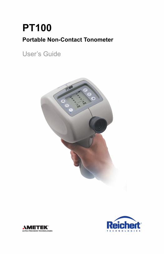
PT100Portable Non-Contact Tonometer
User’s Guide

13850-101-Rev. L2
©2016 AMETEK, Inc.
Reichert and Reichert Technologies are registered trademarks of Reichert, Inc.
AMETEK is a registered trademark of AMETEK, Inc.
All other trademarks are property of their respective owners.
The information contained in this document was accurate at time of publication. Specifications subject to change without notice. Reichert, Inc. reserves the right to make changes in the product described in this manual without notice and without incorporating those changes in any products already sold.
ISO 9001/13485 Certified – Reichert products are designed and manufactured under quality pro-cesses meeting ISO 9001/13485 requirements.
No part of this publication may be reproduced, stored in a retrieval system, or transmitted in any form or by any means, electronic, mechanical, recording, or otherwise, without the prior written permission of Reichert, Inc.
Caution: Federal law restricts this device to sale by or on the order of a licensed physician. Rx only.
13850-101-Rev. L 3
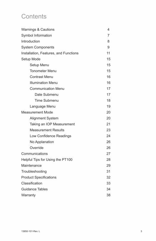
Warnings & Cautions 4
Symbol Information 7
Introduction 8
System Components 9
Installation, Features, and Functions 11
Setup Mode 15
Setup Menu 15
Tonometer Menu 15
Contrast Menu 16
Illumination Menu 16
Communication Menu 17
Date Submenu 17
Time Submenu 18
Language Menu 19
Measurement Mode 20
Alignment System 20
Taking an IOP Measurement 21
Measurement Results 23
Low Confidence Readings 24
No Applanation 26
Override 26
Communications 27
Helpful Tips for Using the PT100 28
Maintenance 29
Troubleshooting 31
Product Specifications 32
Classification 33
Guidance Tables 34
Warranty 38
Contents
13850-101-Rev. L4
Warnings & Cautions
Reichert Technologies (Reichert) is not responsible for the safety and reliability of this instrument when:
• Assembly, disassembly, repair, or modification is made by unauthorizeddealers or persons.• Instrument is not used in accordance with this User’s Guide.
WARNING: AN INSTRUCTION THAT DRAWS ATTENTION TO RISK OF INJURY OR DEATH.
WARNING:THIS INSTRUMENT SHOULD BE USED IN STRICT ACCOR-DANCE WITH THE INSTRUCTIONS OUTLINED IN THIS USER’S GUIDE. THE SAFETY OF THE OPERATOR AND THE PERFORMANCE OF THE INSTRUMENT CANNOT BE GUARANTEED IF USED IN A MANNER NOT SPECIFIED BY REICHERT TECHNOLOGIES.
WARNING:ANY REPAIR OR SERVICE TO THIS INSTRUMENT MUST BE PERFORMED BY EXPERIENCED PERSONNEL OR DEALERS WHO ARE TRAINED BY REICHERT SO THAT CORRECT OPERATION OF THIS INSTRUMENT IS MAINTAINED.
WARNING:DO NOT REPAIR OR SERVICE THIS INSTRUMENT WITHOUT AUTHORIZATION FROM THE MANUFACTURER. ANY REPAIR OR SER-VICE TO THIS INSTRUMENT MUST BE PERFORMED BY EXPERIENCED PERSONNEL OR DEALERS WHO ARE TRAINED BY REICHERT OR SERIOUS INJURY TO THE OPERATOR OR PATIENT MAY OCCUR.
WARNING:MODIFICATIONS TO THIS INSTRUMENT ARE NOT AL-LOWED. ANY MODIFICATION TO THIS UNIT MUST BE AUTHORIZED BY REICHERT OR SERIOUS INJURY TO THE OPERATOR OR PATIENT MAY OCCUR.
WARNING:IF THIS INSTRUMENT IS MODIFIED, APPROPRIATE INSPEC-TION AND TESTING MUST BE CONDUCTED TO ENSURE CONTINUED SAFE USE OF THIS INSTRUMENT.
WARNING:TO AVOID RISK OF ELECTRIC SHOCK, THIS EQUIPMENT MUST ONLY BE CONNECTED TO A SUPPLY MAINS WITH PROTECTIVE EARTH OR DAMAGE TO THE PT100 AND/OR INJURY TO THE OPERATOR OR PATIENT MAY OCCUR.
WARNING: THIS INSTRUMENT CONTAINS A LITHIUM ION BATTERY INSIDE THE REPLACEABLE BATTERY HANDLE. REPLACE THE BATTERY WITH REICHERT PART (P/N 13851-873) ONLY. USE OF ANOTHER BATTERY MAY CAUSE FIRE OR EXPLOSION.
WARNING: DO NOT PLACE A SHORTING DEVICE BETWEEN THE BATTERY TERMINALS, OR ALLOW THE BATTERY TO BECOME WET. DO NOT DISASSEMBLE OR DISPOSE OF THE BATTERY IN A FIRE. MISUSE OR IMPROPER DISPOSAL OF THIS BATTERY MAY CAUSE IT TO BECOME VERY HOT, IGNITE, OR EXPLODE. DAMAGE TO THIS INSTRUMENT AND/OR SERIOUS PERSONAL INJURY MAY RESULT.

13850-101-Rev. L 5
Warnings & Cautions (Continued)
WARNING: DO NOT USE THIS INSTRUMENT IF THERE IS EVIDENCE OF FLUID LEAKING FROM THE BATTERY HANDLE. BATTERIES AND OTHER ELECTRONIC DEVICES MAY CONTAIN FLUIDS THAT ARE HAZARDOUS TO YOUR HEALTH. DIRECT CONTACT WITH SUCH FLUIDS MAY CAUSE BURNS, BLINDNESS, OR DEATH.
WARNING:USE ONLY THE CHARGING DEVICE PROVIDED WITH THIS INSTRUMENT. USE OF ANY OTHER CHARGING DEVICE COULD RESULT IN DAMAGE TO THE INSTRUMENT AND/OR SERIOUS PERSONAL INJURY.
WARNING: DO NOT ALLOW THIS INSTRUMENT TO BE USED BY CHILDREN OR UNTRAINED PERSONS WHO ARE UNFAMILIAR WITH ITS OPERATION AND FUNCTIONS. DAMAGE TO THE UNIT AND OR SERIOUS INJURY MAY OCCUR IF IMPROPERLY USED.
WARNING:THE EQUIPMENT OR SYSTEM SHOULD NOT BE USED ADJACENT TO OR STACKED WITH OTHER EQUIPMENT AND THAT IF ADJACENT OR STACKED USE IS NECESSARY, THE EQUIPMENT OR SYSTEM SHOULD BE OBSERVED TO VERIFY NORMAL OPERATION IN THE CONFIGURATION IN WHICH IT WILL BE USED.
WARNING:THIS INSTRUMENT IS NOT SUITABLE FOR USE IN THE PRESENCE OF FLAMMABLE ANESTHETIC MIXTURES SUCH AS OXYGEN OR NITROUS OXIDE.
WARNING:UNITED STATES FEDERAL LAW AND EUROPEAN REGULATIONS REQUIRE THAT THIS DEVICE BE PURCHASED ONLY BY A PHYSICIAN OR A PERSON ACTING ON BEHALF OF A PHYSICIAN.
WARNING: ENSURE THAT THE VOLTAGE APPLIED TO THE UNIT IS THE SAME AS THE VOLTAGE THAT IS INDICATED ON THE DATA PLATE OR DAMAGE TO THE UNIT MAY OCCUR.
WARNING:THE INSTRUMENT MUST BE PLUGGED INTO AN OUTLET WITH AN EARTH GROUND. DO NOT REMOVE OR DEFEAT THE EARTH GROUND CONNECTION ON POWER INPUT CONNECTOR OR THE UNIT’S POWER CORD OF THIS INSTRUMENT OR DAMAGE TO IT AND/OR INJURY TO THE OPERATOR OR PATIENT MAY OCCUR.
WARNING: THE BATTERY SHOULD ONLY BE REPLACED WITH THE BATTERY SPECIFIED IN THIS MANUAL. USE OF ANOTHER BATTERY MAY CAUSE FIRE OR AN EXPLOSION.
WARNING: DO NOT EXPOSE THE BATTERIES TO TEMPERATURES ABOVE 140ºF, DISASSEMBLE THE BATTERIES, OR DAMAGE TO THIS UNIT AND/OR SERIOUS PERSONAL INJURY MAY RESULT.
WARNING: NEVER ALLOW LIQUID LEAKING FROM THE BATTERY TO GET IN YOUR EYES OR MOUTH AS THIS LIQUID COULD CAUSE SERIOUS PERSONAL INJURY. IF IT COMES IN CONTACT WITH YOUR EYES OR MOUTH, FLUSH THEM IMMEDIATELY WITH PLENTY OF WATER AND CONSULT A PHYSICIAN.
13850-101-Rev. L6
Warnings & Cautions (Continued)
CAUTION: AN INSTRUCTION THAT DRAWS ATTENTION TO THE RISK OF DAM-AGE TO THE PRODUCT.
CAUTION: THE INTERNAL CIRCUITRY OF THE INSTRUMENT CONTAINS ELECTROSTATIC DISCHARGE SENSITIVE DEVICES (ESDS) THAT MAY BE SENSITIVE TO STATIC CHARGES PRODUCED BY THE HUMAN BODY. DO NOT REMOVE THE COVERS WITHOUT TAKING PROPER ESDS PRECAUTIONS.
CAUTION: USE OF AMMONIA BASED CLEANERS ON THE LIQUID CRYSTAL DISPLAY (LCD) MAY CAUSE DAMAGE TO THE DISPLAY. SEE MAINTENANCE SECTION FOR DETAILED CLEANING INSTRUCTION.
CAUTION: DO NOT USE ANY SOLVENTS OR STRONG CLEANING SOLUTIONS ON ANY PART OF THIS INSTRUMENT OR DAMAGE TO THE UNIT MAY OCCUR.
CAUTION: MEDICAL ELECTRONIC EQUIPMENT NEEDS SPECIAL PRECAUTIONS REGARDING EMC AND NEEDS TO BE INSTALLED AND PUT INTO SERVICE ACCORDING TO THE EMC INFORMATION PROVIDED IN THE ACCOMPANYING DOCUMENTS.
CAUTION: PORTABLE AND MOBILE RF COMMUNICATIONS EQUIPMENT CAN AFFECT MEDICAL ELECTRICAL EQUIPMENT.
CAUTION: THIS INSTRUMENT IS NOT TO BE USED NEAR HIGH-FREQUENCY EMITTING SURGICAL EQUIPMENT.

13850-101-Rev. L 7
Symbol Information
The following symbols appear on the instrument:
Caution symbol indicating important operating and maintenance instructions that are included in this User’s Guide
Alternating Current Power
Protective Earth Connection
ON / OFF
Manufacturer
Date of Manufacture
REF Catalog Number
SN Serial Number
Waste of Electrical and Electronic Equipment
Compliance to Medical Device Directive 93/42/EEC
Authorized to mark given by Intertek ETL Semko for conformance with electrical standards
Consult Instructions for Use
Fragile Contents in Shipping Container - handle with care
Keep Dry - Package shall be kept away from rain.
This Way Up - Indicates correct upright position of package
Authorized Representative in European Community
2016
13850-101-Rev. L8
Introduction
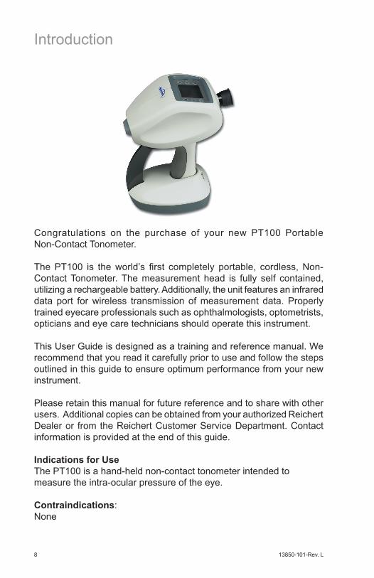
Congratulations on the purchase of your new PT100 Portable Non-Contact Tonometer.
The PT100 is the world’s first completely portable, cordless, Non- Contact Tonometer. The measurement head is fully self contained, utilizing a rechargeable battery. Additionally, the unit features an infrared data port for wireless transmission of measurement data. Properly trained eyecare professionals such as ophthalmologists, optometrists, opticians and eye care technicians should operate this instrument.
This User Guide is designed as a training and reference manual. We recommend that you read it carefully prior to use and follow the steps outlined in this guide to ensure optimum performance from your new instrument.
Please retain this manual for future reference and to share with other users. Additional copies can be obtained from your authorized Reichert Dealer or from the Reichert Customer Service Department. Contact information is provided at the end of this guide.
Indications for UseThe PT100 is a hand-held non-contact tonometer intended to measure the intra-ocular pressure of the eye.
Contraindications:None

13850-101-Rev. L 9
PT100 System (P/N 13850)1. Charging Base2. Transport Case3. Battery Handle 4. PT100 Measurement Head
PT100 Measurement Head (P/N 13851) 7. Display and Controls 8. Nosepiece 9. Infrared Data Window10. Battery Handle11. Charging Contacts12. On/Off Switch13. Eyepiece
System Components

13850-101-Rev. L10
System Components (Continued)
Charging Base (P/N 13852)14. Charging Contacts15. Charging Indicator (amber)16. Power Indicator (green)
Accessories:• PT100 Carrying Case (13850-300)• Battery Handle (13851-853; Without ON/OFF Button)
(13851-873; With ON/OFF Button)• Slit Lamp Holder (13854) - Optional• Wrist Strap (13851-096)• Dust Cover (13850-001)• User’s Guide (13850-101)• Quick Reference Card (13850-104)• Eye Guard (13851-021)• Thermal Printer (13853) - Optional• Paper - Thermal (12441)• Power Cord (WCBL 10018, for 110 VAC)
(WCBL 10027, for 220 VAC)

13850-101-Rev. L 11
Installation, Features, and Functions
PT100 SetupThe PT100 is supplied in a convenient carrying case for easy and safe transportation to remote locations. To setup the PT100, remove all of the components and follow these instructions.WARNING: POSITION THE PT100 SO THAT IT IS NOT DIFFICULT TO OPERATE THE DISCONNECTION DEVICE (PLUG).
WARNING: CARE MUST BE TAKEN TO ARRANGE THE CABLES FOR THE ACCESSO-RIES SUCH THAT THEY DO NOT PRESENT A TRIPPING HAZARD TO THE EXAMINER OR A DANGER TO THE PATIENT.
Full charging of the battery is required be-fore using the PT100.• Plug the female end of the power cord
into the connector on the underside of the charging base and press the cord neatly into the cord-retainer channel.
• Plug the male end of the cord into a power outlet (100 to 240 VAC @ 50 to 60 Hz). The green LED will illuminate to indicate that the base has power and the amber LED will flash to indicate the base is in standby mode.
• Place the PT100 into the charging base, making sure that it is seated properly and that the ON/OFF switch is placed in the OFF position. The Amber light will illuminate. It will take about 3 hours to fully charge the battery. A full charge will ensure maximum battery life.
Note: The instrument will charge in the ON position, however, the pro-cess is slower and it will take longer to achieve a full charge. • When the PT100 is fully charged the amber LED will go out. If the
PT100 is in the charging base and the amber LED is blinking, the unit is not fully seated.
• Once charged, the instrument has an operational usage of approximately 350 individual measurements before recharg-ing is required. Operational usage will vary depending on the use of features such as IR data transmission and patient illumination. In order to conserve the charge, users should keep the power switch on the handle to the OFF (O) position.
Note: If the PT100 is not used for extended peri-ods of time, the battery should be removed and placed in its location in the carrying case..

13850-101-Rev. L12
PT100 InitiationThe PT100 utilizes a user-friendly icon-based operating system to ensure ease of use. To initiate the system, simply press any of the function buttons on the control panel.
Battery IndicatorThe PT100 has a battery indicator located in the upper right-hand corner of the display. The amount of charge is indicated by the black fill inside the battery icon. The battery is fully charged when the icon is completely black.
The black fill moves from right to left (towards the “head” of the battery) while charging. During instrument use, the black fill moves from left to right to indicate the amount of charge remaining.
Sleep ModeTo conserve battery power, the PT100 has a sleep mode that activates after 2 minutes of inactivity. Press any button to bring the instrument out of sleep mode. The LCD screen will turn on and the instrument will
be ready for use. In addition to the display being on, the blue alignment crosshair, viewed through the eyepiece, indicates that the instrument is on. If the crosshair is not visible the PT100 is in sleep mode. When bringing the instrument out of sleep mode, be careful to press a button only once. Pressing a button more than once may in-advertently turn an instrument function on or off.
Optional Printer Setup (available, but not included)The printer available for the PT100 system is a battery powered, wire-less, infrared printer. Batteries are included. Remove the printer from its packaging and follow the instructions provided in the communication section of this manual.
Installation, Features, and Functions (Cont’d)
On/Off SwitchThe PT100 is equipped with an On/Off switch located on the lower left side of the handle. To power on the instrument, slide the switch toward the I symbol, which indicates the ON position. To power off the instrument, slide the switch toward the O symbol, which indicates the OFF position.

13850-101-Rev. L 13
Control Panel Functions The illustration below identifies the control panel icons and button functions. Press any button to proceed to the measurement screen.
Function IconsDEMO Press to allow patient to feel demonstration air puff.
OVERRIDE Permits quicker measurement of difficult patients.
SETUP Enables access to the setup menu of the instrument.
LEFT/RIGHT Press to select the patient’s left or right eye.
PRINT Transmits measurement data to printer or IR device.
CLEAR Erases current measurement data from display screen.
Setup Iconsup In setup mode, moves up through menu options.
down In setup mode, moves down through menu options.
select In setup mode, activates the selected setting.
Installation, Features, and Functions (Cont’d)
13850-101-Rev. L14
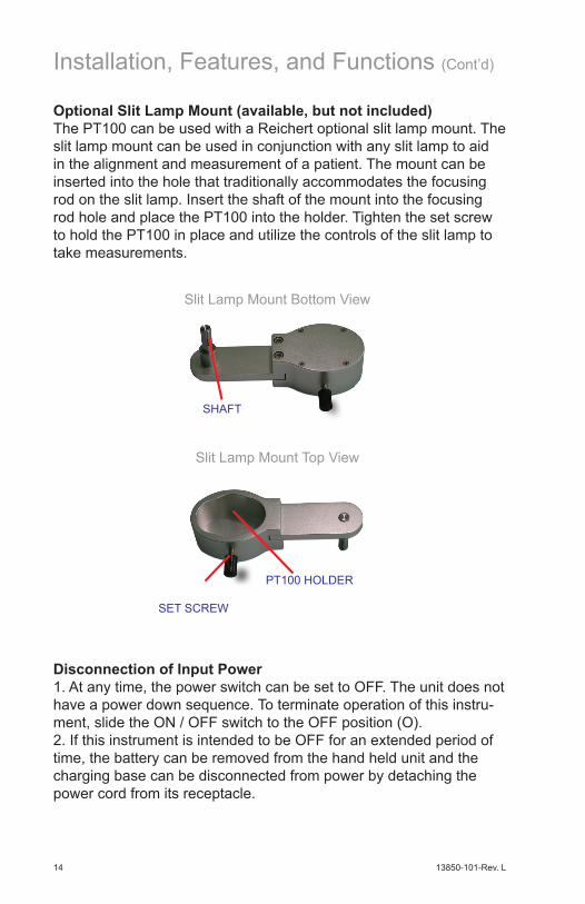
Optional Slit Lamp Mount (available, but not included)The PT100 can be used with a Reichert optional slit lamp mount. The slit lamp mount can be used in conjunction with any slit lamp to aid in the alignment and measurement of a patient. The mount can be inserted into the hole that traditionally accommodates the focusing rod on the slit lamp. Insert the shaft of the mount into the focusing rod hole and place the PT100 into the holder. Tighten the set screw to hold the PT100 in place and utilize the controls of the slit lamp to take measurements.
Slit Lamp Mount Bottom View
Slit Lamp Mount Top View
SHAFT
SET SCREW
PT100 HOLDER
Installation, Features, and Functions (Cont’d)
Disconnection of Input Power1. At any time, the power switch can be set to OFF. The unit does not have a power down sequence. To terminate operation of this instru-ment, slide the ON / OFF switch to the OFF position (O).2. If this instrument is intended to be OFF for an extended period of time, the battery can be removed from the hand held unit and the charging base can be disconnected from power by detaching the power cord from its receptacle.

13850-101-Rev. L 15
Setup Mode
To enter the SETUP mode press the SETUP button on the lower left side of the control panel. Once the instrument is in SETUP mode, the opera-tor can navigate and activate menu options by using the UP, DOWN, and SELECT buttons. The arrow, to the left of the menu choices on the display, will move up or down indicating the option to be selected. To activate selected options simply press the SELECT button.
The following options can be set by the operator:
Tonometer MenuThis menu option allows operators to choose the output format of the measurement results. The available options are mmHg (millimeters of mercury) and KPa (kilopascals). Current instrument settings are indicated by highlighting around the characters. Use the UP, DOWN, and SELECT buttons to navigate and activate the options. The factory default is mmHg.
Setup MenuThe PT100 comes configured with the most commonly used instru-ment settings. Default settings can be changed in the setup mode. Once changes are made, they will remain set until further changes are made.
13850-101-Rev. L16
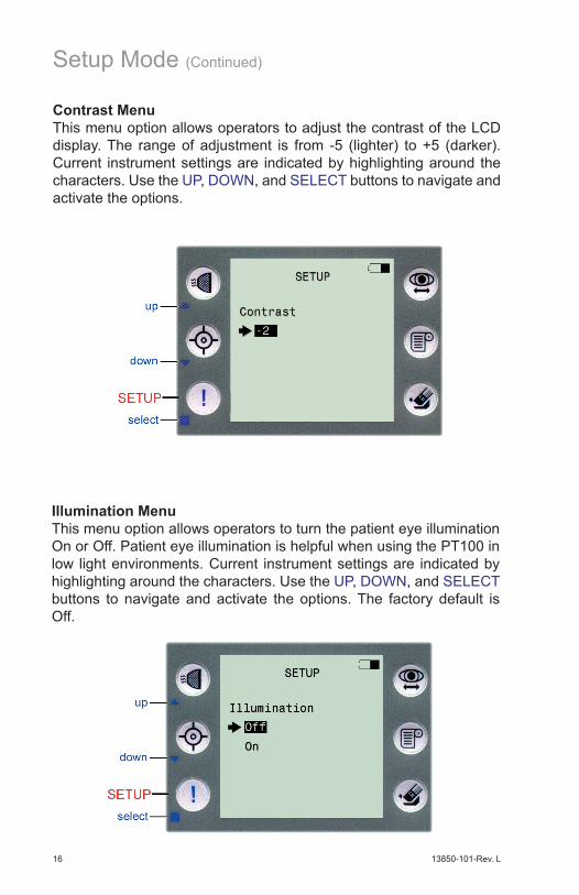
Contrast MenuThis menu option allows operators to adjust the contrast of the LCD display. The range of adjustment is from -5 (lighter) to +5 (darker). Current instrument settings are indicated by highlighting around the characters. Use the UP, DOWN, and SELECT buttons to navigate and activate the options.
Illumination MenuThis menu option allows operators to turn the patient eye illumination On or Off. Patient eye illumination is helpful when using the PT100 in low light environments. Current instrument settings are indicated by highlighting around the characters. Use the UP, DOWN, and SELECT buttons to navigate and activate the options. The factory default is Off.
Setup Mode (Continued)
13850-101-Rev. L 17
Setup Mode (Continued)
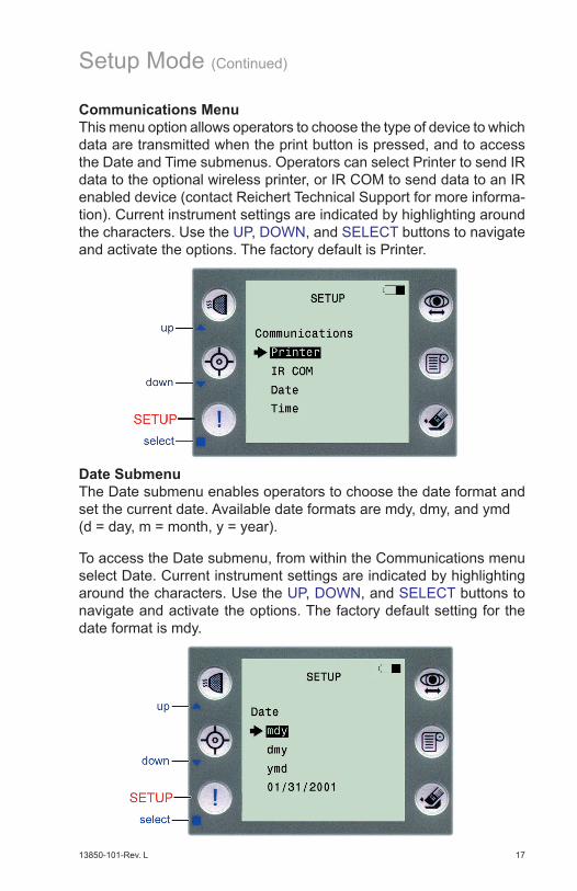
Communications MenuThis menu option allows operators to choose the type of device to which data are transmitted when the print button is pressed, and to access the Date and Time submenus. Operators can select Printer to send IR data to the optional wireless printer, or IR COM to send data to an IR enabled device (contact Reichert Technical Support for more informa-tion). Current instrument settings are indicated by highlighting around the characters. Use the UP, DOWN, and SELECT buttons to navigate and activate the options. The factory default is Printer.
Date SubmenuThe Date submenu enables operators to choose the date format and set the current date. Available date formats are mdy, dmy, and ymd (d = day, m = month, y = year).
To access the Date submenu, from within the Communications menu select Date. Current instrument settings are indicated by highlighting around the characters. Use the UP, DOWN, and SELECT buttons to navigate and activate the options. The factory default setting for the date format is mdy.
13850-101-Rev. L18
Setup Mode (Continued)
To set the current date, move the arrow to the bottom line and press select. The first two characters will be highlighted. Use the UP and DOWN buttons to change the characters. Press SELECT when the desired setting has been attained. Repeat this procedure until all date fields (year, month, and day) are set. Upon completing the last field the operator will be returned to the main SETUP menu.
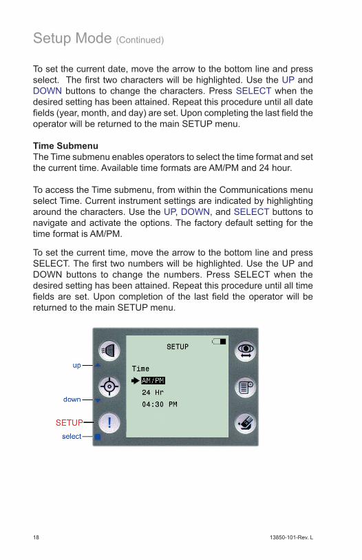
Time SubmenuThe Time submenu enables operators to select the time format and set the current time. Available time formats are AM/PM and 24 hour.
To access the Time submenu, from within the Communications menu select Time. Current instrument settings are indicated by highlighting around the characters. Use the UP, DOWN, and SELECT buttons to navigate and activate the options. The factory default setting for the time format is AM/PM.
To set the current time, move the arrow to the bottom line and press SELECT. The first two numbers will be highlighted. Use the UP and DOWN buttons to change the numbers. Press SELECT when the desired setting has been attained. Repeat this procedure until all time fields are set. Upon completion of the last field the operator will be returned to the main SETUP menu.
13850-101-Rev. L 19
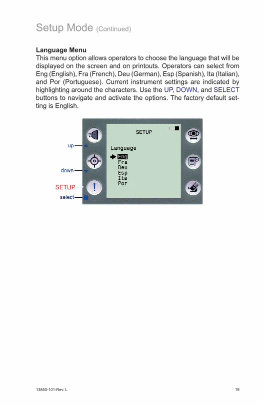
Language MenuThis menu option allows operators to choose the language that will be displayed on the screen and on printouts. Operators can select from Eng (English), Fra (French), Deu (German), Esp (Spanish), Ita (Italian), and Por (Portuguese). Current instrument settings are indicated by highlighting around the characters. Use the UP, DOWN, and SELECT buttons to navigate and activate the options. The factory default set-ting is English.
Setup Mode (Continued)
13850-101-Rev. L20
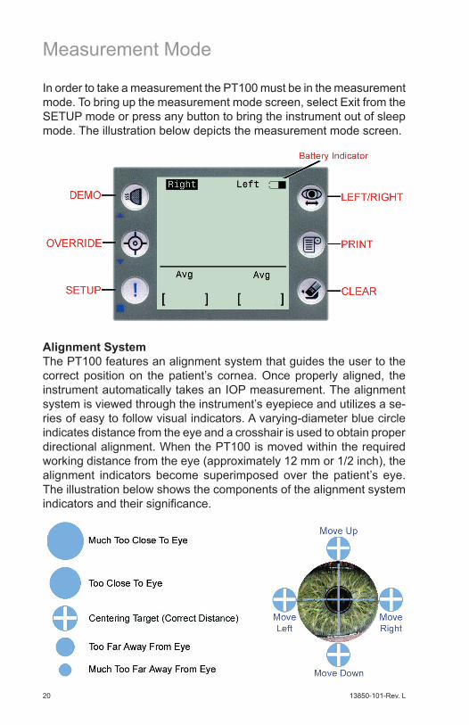
Measurement Mode
Alignment SystemThe PT100 features an alignment system that guides the user to the correct position on the patient’s cornea. Once properly aligned, the instrument automatically takes an IOP measurement. The alignment system is viewed through the instrument’s eyepiece and utilizes a se-ries of easy to follow visual indicators. A varying-diameter blue circle indicates distance from the eye and a crosshair is used to obtain proper directional alignment. When the PT100 is moved within the required working distance from the eye (approximately 12 mm or 1/2 inch), the alignment indicators become superimposed over the patient’s eye. The illustration below shows the components of the alignment system indicators and their significance.
In order to take a measurement the PT100 must be in the measurement mode. To bring up the measurement mode screen, select Exit from the SETUP mode or press any button to bring the instrument out of sleep mode. The illustration below depicts the measurement mode screen.

13850-101-Rev. L 21
The operator will see the align-ment crosshair in the center of the eyepiece. The circular distance indicator will appear in the field of view. Initially, the operator should use the dis-tance indicator to establish the correct distance from the eye. Move the PT100 either closer to the eye or further from the eye, following the cues given by the indicator. Correct distance has been achieved when the indicator displays a cross.
Taking an IOP MeasurementOperators should hold the PT100 with two hands. Place one hand on the handle and the other between the top-front of the instrument and the patient’s brow. This will help stabilize the instrument and serves as a good starting point for establishing correct distance from the eye.
Measurement Mode (Continued)
Once the correct distance has been established, simply move the PT100 to position the crosshair over the centering target. As the operator attempts to align the crosshair, the distance indicator may change position and size. Continue to move the instrument until the crosshair is positioned directly over the centering target at the correct distance.
Press the LEFT/RIGHT button to select the eye to be measured. Using the two-handed method described above, position the PT100 in front of the patient. Look through the eyepiece and move the PT100, positioning the blue crosshair over the pupil. Instruct the patient to open their eyes wide and look at the green fixation spot. Slowly move the PT100 towards the eye until the alignment system activates. The working distance is approximately 12mm (1/2”) from the eye.
13850-101-Rev. L22
Measurement Mode (Continued)
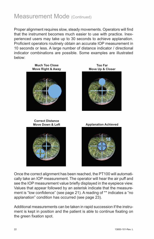
Proper alignment requires slow, steady movements. Operators will find that the instrument becomes much easier to use with practice. Inex-perienced users may take up to 30 seconds to achieve applanation. Proficient operators routinely obtain an accurate IOP measurement in 10 seconds or less. A large number of distance indicator / directional indicator combinations are possible. Some examples are illustrated below:
Once the correct alignment has been reached, the PT100 will automati-cally take an IOP measurement. The operator will hear the air puff and see the IOP measurement value briefly displayed in the eyepiece view. Values that appear followed by an asterisk indicate that the measure-ment is “low confidence” (see page 21). A reading of ** indicates a “no applanation” condition has occurred (see page 23).
Additional measurements can be taken in rapid succession if the instru-ment is kept in position and the patient is able to continue fixating on the green fixation spot.
Much Too CloseMove Right & Away
Too FarMove Up & Closer
Applanation AchievedCorrect Distance
Move Down & Left
13850-101-Rev. L 23
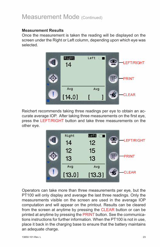
Measurement ResultsOnce the measurement is taken the reading will be displayed on the screen under the Right or Left column, depending upon which eye was selected.
Measurement Mode (Continued)
Reichert recommends taking three readings per eye to obtain an ac-curate average IOP. After taking three measurements on the first eye, press the LEFT/RIGHT button and take three measurements on the other eye.
Operators can take more than three measurements per eye, but the PT100 will only display and average the last three readings. Only the measurements visible on the screen are used in the average IOP computation and will appear on the printout. Results can be cleared from the screen at anytime by pressing the CLEAR button or can be printed at anytime by pressing the PRINT button. See the communica-tions instructions for further information. When the PT100 is not in use, place it back in the charging base to ensure that the battery maintains an adequate charge.
13850-101-Rev. L24
Measurement Mode (Continued)
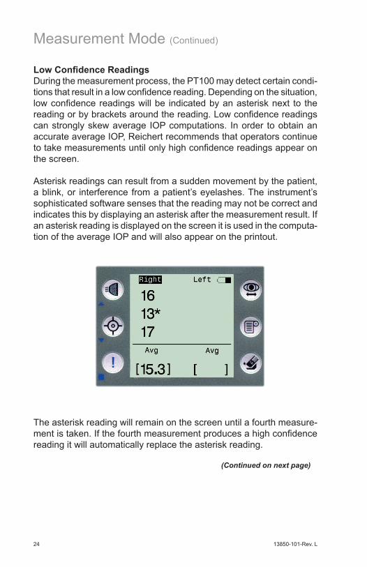
Low Confidence ReadingsDuring the measurement process, the PT100 may detect certain condi-tions that result in a low confidence reading. Depending on the situation, low confidence readings will be indicated by an asterisk next to the reading or by brackets around the reading. Low confidence readings can strongly skew average IOP computations. In order to obtain an accurate average IOP, Reichert recommends that operators continue to take measurements until only high confidence readings appear on the screen.
Asterisk readings can result from a sudden movement by the patient, a blink, or interference from a patient’s eyelashes. The instrument’s sophisticated software senses that the reading may not be correct and indicates this by displaying an asterisk after the measurement result. If an asterisk reading is displayed on the screen it is used in the computa-tion of the average IOP and will also appear on the printout.
The asterisk reading will remain on the screen until a fourth measure-ment is taken. If the fourth measurement produces a high confidence reading it will automatically replace the asterisk reading.
(Continued on next page)

13850-101-Rev. L 25
Measurement Mode (Continued)
Low Confidence Readings (Continued)Bracket readings will only appear on the screen after 3 measurements have been taken on the same eye. The PT100 compares all three measurements, looking for a reading that is more than 4 mmHg higher or lower than the other two.
PT100 measurements are made in milliseconds and occur at random to the cardiac-related ocular pulse. As a result, measurement fluctua-tions of 2 - 4 mmHg should be considered normal. However, certain situations, such as sudden movements or blinks, may cause larger measurement fluctuations. When a fluctuation of more than 4 mmHg occurs, the reading will be bracketed. If a bracketed reading is displayed on the screen it is used in the computation of the average IOP and will also appear on the printout.
A bracketed reading will remain on the screen until a fourth measure-ment is taken. If the fourth measurement produces a high confidence reading, the bracketed reading will be automatically replaced by the new measurement.
Note: Brackets will not appear in the heads-up display as seen through the eyepiece, since only single measurement values are displayed here. Bracketed values only appear on the LCD screen in connection with other significantly different measurement values.

13850-101-Rev. L26
No ApplanationDuring the measurement process, the PT100 may detect certain condi-tions that cause “No Applanation” to be displayed on the screen. No Applanation readings can occur for various reasons including sudden movements, blinks, and corneal disorders.
Measurement Mode (Continued)
If a No Applanation reading occurs, the message will be displayed on the screen for only three seconds and has no impact on any previous or future measurement results. After the message disappears the in-strument will revert to the measurement screen.
OverrideSome patients may be difficult to measure due to an inability to fixate, corneal scarring, or corneal disorders (for example, Fuchs Dystrophy). If an experienced operator is having a difficult time achieving applana-tion on such a patient, the override function may help. Pressing the OVERRIDE button enables easier measurement by widening the instru-ment’s auto-measurement zone. However, the results obtained with override may be less accurate. The override symbol will appear on the screen and on the printout next to any override measurements.

13850-101-Rev. L 27
The PT100 uses infrared data transmission to send measurement data to the optional printer or user-supplied IR enabled devices (con-tact Reichert Technical Support for more information). Measurements that appear on the screen can be printed at anytime by pointing the IR window of the PT100 at the IR window on the printer and pressing the PRINT button. An hourglass symbol will appear at the top of the PT100 display during data transmission. Operators should continue to point the PT100 towards the printer until the hourglass disappears (approximately 3 seconds).
Communications
After transmission the screen will clear. If the data do not print properly press the PRINT button again even though the readings no longer appear on the screen. The PT100 retains data in memory until a new measurement is taken or CLEAR is pressed.
Always make sure the printer is on and not in sleep mode. According to the printer manufacturer’s instructions, the PT100 should be no more than 18 inches from the printer and should be in line with the printer’s IR window within 30 degrees left or right of center and no more than 20 degrees above or 10 degrees below the printer. Please review the instruction manual supplied with the printer for more information.
13850-101-Rev. L28
As with most new instruments, operator training and technique are es-sential to achieving accurate results quickly. Reichert recommends that PT100 operators spend at least 30 minutes familiarizing themselves with the instrument before attempting to use it on patients. Once operators have mastered the technique, the PT100 is very easy to use.
In order to become proficient with the PT100, Reichert recommends the following:
Helpful Tips for Using the PT100
Use both hands when operating the PT100. One to hold the instrument and the other to act as a support between the patient’s forehead and the top-front of the instrument. On the grip-hand, operators should extend their index finger along the underside of the unit to provide additional stabilization.
When aligning the PT100, use very slow movements. The sophisticated alignment system responds very quickly to even the slightest movements.
It may be difficult to measure a patient whose head is significantly higher or lower than the operator’s. Use whatever means are available to achieve near eye-level positioning (chairs, stools, etc).
If the patient is seated, stabilize their head using the headrest on the chair if one is available.
Ask the patient to hold their eye wide open and try not to blink. Some patients have a tendency to close the eye not being tested. Instruct patients to keep both eyes open during the measurement process. This will enable a wider opening of the eye being tested.
Use the patient’s pupil as an initial alignment guide when centering the instrument.
After taking the first measurement, instead of pulling the PT100 away to look at the results, keep it in position for the next measurement. Operators will find that they are able to take a second and third reading in rapid succession.
In order to provide increased stability when standing, the operator and the patient should position their legs approximately shoulder width apart, bend the knees slightly, place one foot further forward than the other, and lean towards each other.

13850-101-Rev. L 29
Maintenance
Due to its advanced design, the PT100 requires very little routine maintenance. Periodic cleaning of the nosepiece and display screen, infrequent battery replacement, and possible fuse replacement are all that may be required. If you have any questions about maintenance of the PT100, contact your local dealer or Reichert Customer Service at the address shown on the rear cover of this guide.
CleaningDo not use alcohol, methanol, acetone, or any other solvents when clean-ing the PT100. Damage could occur causing possible malfunctions.
Clean the end of the nosepiece with a clean, lint-free cloth that is very lightly dampened with a mild soap solution (2 cc of liquid soap to 1 liter of distilled water). The frequency of cleaning will depend on the condi-tions and amount of use. Clean as required.
Battery ReplacementEventually the battery will no longer hold a charge for an acceptable length of time. This is an indication that the battery should be replaced. New battery handle assemblies are available from your Authorized Reichert Dealer or Reichert Customer Service.
Replace the battery with Reichert part (P/N 13851-873) only. Use of another battery may cause fire or explosion. The battery may explode if mistreated. Do not disassemble or dispose of the battery in a fire.
To replace the battery:• Insert a flat-blade screwdriver into
the slot at the bottom of the patient’s side of the battery handle.
• Lightly press down on the handle of the screwdriver so that the blade pushes up and releases the locking clip of the battery handle.
• Pull the battery handle out of the unit and disengage the wire connector from the PT100.
• Insert the connector of the new battery into the receptacle and position the replaceable battery handle into the PT100 measure-ment head.
• Press the assembly into place, ensuring that the locking clip properly secures the replaceable battery handle.
Note: If the PT100 is not used for extended periods of time, the battery should be removed and placed in its location in the carrying case.

13850-101-Rev. L30
Fuse ReplacementFuses are located on the bottom of the charging base near the power cord receptacle. If required, replace with fuses as indicated in the Specifications section of this manual.
WARNING: ANY REPAIR OR SERVICE TO THIS INSTRUMENT MUST BE PER-FORMED BY EXPERIENCED PERSONNEL OR DEALERS WHO ARE TRAINED BY REICHERT SO THAT CORRECT OPERATION OF THIS INSTRUMENT IS MAIN-TAINED.
To remove the fuses:• Disconnect input power to the
charging base.• Press down on the release
tab of the Fuse Holder. When the tab is pushed down and has released, the Fuse Holder will disengage from the Power Input Module.
• Remove the fuse holder from the of the Power Input Module.
• Replace the fuses and then push the Fuse Holder back into the Power Input Module.
Maintenance (Continued)
Fuse Holder
Power Input Module
Tab
Fuses
13850-101-Rev. L 31
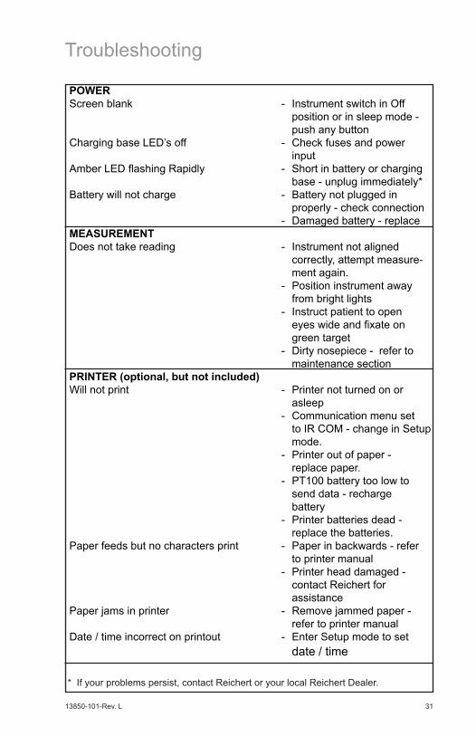
POWER Screen blank - Instrument switch in Off position or in sleep mode - push any button Charging base LED’s off - Check fuses and power inputAmber LED flashing Rapidly - Short in battery or charging base - unplug immediately*Battery will not charge - Battery not plugged in properly - check connection - Damaged battery - replace MEASUREMENT Does not take reading - Instrument not aligned correctly, attempt measure- ment again. - Position instrument away from bright lights - Instruct patient to open eyes wide and fixate on green target - Dirty nosepiece - refer to maintenance sectionPRINTER (optional, but not included) Will not print - Printer not turned on or asleep - Communication menu set to IR COM - change in Setup mode. - Printer out of paper - replace paper. - PT100 battery too low to send data - recharge battery - Printer batteries dead - replace the batteries.Paper feeds but no characters print - Paper in backwards - refer to printer manual - Printer head damaged - contact Reichert for assistancePaper jams in printer - Remove jammed paper - refer to printer manualDate / time incorrect on printout - Enter Setup mode to set date / time
Troubleshooting
* If your problems persist, contact Reichert or your local Reichert Dealer.

13850-101-Rev. L32
Product Specifications
PT100 Measurement HeadHeight.................................................. 10 in. (2.5 cm)Width................................................... 4¾ in. (12 cm)Depth................................................... 7¾ in. (20 cm)Weight, unpacked................................. 2.7 lbs. (1.3 kg)Lithium Ion Battery Voltage................... 3.7 VDC
Charging Base Input Voltage........................................ 100 VAC to 240 VAC Input Current........................................ 124 mA max Input Frequency................................... 50 Hz to 60 HzOutput Voltage...................................... 3.5 VDC to 4.0 VDCOutput Current...................................... 1.0 ADC maxOutput Current...................................... 1.0 ADC maxFuses ................................................... T250V 800ma
Measurement Range.............................. 0 mmHg to 60 mmHgAmbient Operating Temperature Range..0°C (32°F) to +45°C (113°F)
Measurement Accuracy Accuracy by Artificial Eye (95% Confidence) IOP ± 0.75 mmHg (7-60 mmHg)
Environmental:The environmental conditions are as follows:
Operating:Temperature 10° C (50° F) to 35° C (95° F) Relative Humidity: 30% to 75%Atmospheric Pressure: 80 kPa (23.6 in. Hg) to 106 kPa (31.3 in. Hg)
Transportation & Storage:Temperature -20° C (-4° F) to +70° C (158° F)Relative Humidity: (non-condensing) 10% to 90% Atmospheric Pressure: 55 kPa (16.2 in. Hg) to 106 kPa (31.3 in. Hg)
Exposure to extreme temperature conditions indicated above must not exceed 15 weeks.
-20°C
70°C
10%
90%
106 kPa
55 kPa
13850-101-Rev. L 33
DisposalThis product and the lithium ion battery inside it do not generate any environmentally hazardous residues. At the end of the product life, follow local laws and ordinances regarding proper disposal.
Software RevisionThe software revision can be obtained by contacting Reichert Technologies. The serial number identifies the manufacture date and will provide access to the software version.
ClassificationAccording to the type of protection against electrical shock:The PT100 recharging unit is classified as: Class 1 Equipment.The PT100 measurement head is classified as: Internally Powered Equipment.
According to the degree of protection against electrical shock:The PT100 is classified as Class B Equipment.
According to the degree of protection against harmful ingress of water: The PT100 is classified as IPX0 Equipment.
According to the degree of safety of application in the presence of a flam-mable anaesthetic mixture with air or with oxygen or nitrous oxide:The PT100 is not suitable for use in the presence of the above flam-mable mixtures.
Parts and accessories used in this product meet the requirements of the applicable IEC601 series.
Product Specifications (Continued)
13850-101-Rev. L34
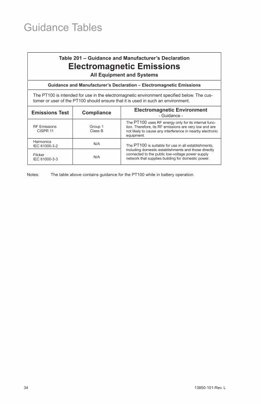
Table 201 – Guidance and Manufacturer’s Declaration
Electromagnetic EmissionsAll Equipment and Systems
Guidance and Manufacturer’s Declaration – Electromagnetic Emissions
The PT100 is intended for use in the electromagnetic environment specified below. The cus-tomer or user of the PT100 should ensure that it is used in such an environment.
Emissions Test Compliance Electromagnetic Environment - Guidance -
RF Emissions CISPR 11
Group 1 Class B
The PT100 uses RF energy only for its internal func-tion. Therefore, its RF emissions are very low and are not likely to cause any interference in nearby electronic equipment.
Harmonics IEC 61000-3-2 N/A The PT100 is suitable for use in all establishments,
including domestic establishments and those directly connected to the public low-voltage power supply network that supplies building for domestic power.
Flicker IEC 61000-3-3 N/A
Guidance Tables
Notes: The table above contains guidance for the PT100 while in battery operation.

13850-101-Rev. L 35
Guidance Tables (Continued)
Notes: The table above contains guidance for the PT100 while in battery operation.
Table 202 – Guidance and Manufacturer’s Declaration
Electromagnetic ImmunityAll Equipment and Systems
Guidance and Manufacturer’s Declaration – Electromagnetic Immunity
The PT100 is suitable for use in electromagnetic environment specified below. The customer or user of the PT100 should ensure that it is used in such an environment.
Immunity Test
IEC 60601 Test Level
Compliance Level
Electromagnetic Environment - Guidance
ESD IEC 61000-4-2
±6kV Contact ±8kV Air
±6kV Contact ±8kV Air
Floors should be wood, concrete or ceramic tile. If floors are synthetic, the R/H should be at least 30%.
EFT IEC 61000-4-4
±2kV Mains ±1kV I/Os
±2kV Mains ±1kV I/Os
Mains power quality should be that of a typical residential, commercial or hospital environ-ment.
Surge IEC 61000-4-5
±1kV Differential ±2kV Common
±1kV Differential ±2kV Common
Mains power quality should be that of a typical residential, commercial or hospital environ-ment.
Voltage Dips/Dropout IEC 61000-4-11
>95% Dip for 0.5 Cycle60% Dip for 5 Cycles30% Dip for 25 Cycles>95% Dip for 5 Seconds
>95% Dip for 0.5 Cycle60% Dip for 5 Cycles30% Dip for 25 Cycles>95% Dip for 5 Seconds
Mains power quality should be that of a typical residential, commercial or hospital environ-ment. If the user of the PT100 requires continued operation during power mains inter-ruptions, it is recommended that the PT100 be powered from an uninterruptible power supply or battery.
Power Frequency 50/60Hz Magnetic Field IEC 61000-4-8
3A/m 3A/mPower frequency magnetic fields should be that of a typical residential, commercial or hospital environment.

13850-101-Rev. L36
Guidance Tables (Continued)
Table 204 – Guidance and Manufacturer’s Declaration
Electromagnetic ImmunityEquipment and Systems that are NOT Life-supporting
Guidance and Manufacturer’s Declaration – Electromagnetic Immunity
The PT100 is intended for use in the electromagnetic environment specified below. The cus-tomer or user of the PT100 should ensure that it is used in such an environment.
Immunity Test
IEC 60601 Test Level
Compliance Level
Electromagnetic Environment - Guidance
Conducted RF IEC 61000-4-6
3 Vrms 150 kHz to 80 MHz
NA Portable and mobile RF communications equipment should be no closer to any part of the PT100, including cables, than the recommended separation distance calcu-lated from the equation applicable to the frequency of the transmitter.
Recommended Separation Distance:
d=(3.5/V1)(Sqrt P)
d=(3.5/E1)(Sqrt P) 80 to 800 MHz
d=(7/E1)(Sqrt P) 800 MHz to 2.5 GHz
Where P is the max output power rating of the transmitter in watts (W) according to the transmitter manufacturer and d is the recom-mended separation distance in meters (m).
Field strengths from fixed transmitters, as determined by an electromagnetic site survey, should be less than the compliance levels in each frequence range.
Interference may occur in the vicinity of equipment marked with the following symbol.
Radiated RF IEC 61000-4-3
80 MHz to 2.5 GHz @ 3V/m
(E1)=3V/m
Note 1: At 80 MHz and 800 MHz, the higher frequency range applies.
Note 2: These guidelines may not apply in all situations. Electromagnetic propagation is affected by absorption and reflection from structures, objects and people.
* Field strengths from fixed transmitters, such as base stations for radio (cellular/cordless) telephones and land mobile radios, amateur radio, AM and FM radio broadcast and TV broadcast cannot be predicted theoretically with accuracy. To assess the electromagnetic environment due to fixed RF transmitters, an electromagnetic site survey should be considered. The measured field strength in the location in which the ME Equipment or ME System should be observed to verify normal operation. If abnormal performance is observed, additional measures many be necessary, such as re-orienting or relocating the ME Equipment or ME System.
* Over the frequency range 150 kHz to 80 MHz, field strengths should be less then [V1] V/m.
Notes: The table above contains guidance for the PT100 while in battery operation.

13850-101-Rev. L 37
Guidance Tables (Continued)
Table 206 – Recommended Separation Distances between Portable and Mobile RF Communications Equipment and the PT100 for ME
Equipment and ME Systems that are NOT Life-supporting.
Guidance and Manufacturer’s Declaration - Electromagnetic Immunity
Recommended Separation Distances for between Portable and Mobile RF Communications Equipment and the PT100
The PT100 is intended for use in the electromagnetic environment in which radiated RF distur-bances are controlled. The customer or user of the PT100 can help prevent electromagnetic interference by maintaining a minimum distance between portable and mobile RF Communica-tions Equipment and the PT100 as recommended below, according to the maximum output power of the communications equipment.
Max Output Power of Trans-
mitter(W)
Separation (m)150kHz to 80 MHz
d=(3.5/V1)(Sqrt P)
Separation (m)80 to 800 MHzd=(3.5/E1)(Sqrt P)
Separation (m)800MHz to 2.5GHz
d=(7/E1)(Sqrt P)
0.01 N/A in Battery Mode 0.1166 0.23330.1 N/A in Battery Mode 0.3689 0.73781 N/A in Battery Mode 1.1666 2.333310 N/A in Battery Mode 3.6893 7.3786100 N/A in Battery Mode 11.6666 23.3333
For transmitters rated at a maximum output power not listed above, the recommended separation distance (d) in meters (m) can be estimated using the equation applicable to the frequency of the transmitter, where P is the maximum output power rating of the transmitter in watts (w) according to the transmitter manufacturer.Note 1: At 80 MHz and 800 MHz, the separation distance for the higher frequency range applies.Note 2: These guidelines may not apply in all situations. Electromagnetic propagation is affected by absorption and reflection from structures, objects, and people.
Notes: The table above contains guidance for the PT100 while in battery operation.

13850-101-Rev. L38
Warranty
This product is warranted by Reichert, Inc. against defective material and workmanship under normal use for a period of one year from the date of invoice to the original purchaser. (An authorized dealer shall not be considered an original purchaser.) Under this warranty, Reichert’s sole obligation is to repair or replace the defective part or product at Reichert’s discretion.
This warranty applies to new products and does not apply to a product that has been tampered with, altered in any way, misused, damaged by accident or negligence, or which has had the serial number removed, altered or effaced. Nor shall this warranty be extended to a product installed or operated in a manner not in accordance with the applicable Reichert instruction manual, nor to a product which has been sold, ser-viced, installed or repaired other than by a Reichert factory, Technical Service Center, or authorized Reichert Dealer.
Lamps, bulbs, charts, cards and other expendable items are not cov-ered by this warranty.
All claims under this warranty must be in writing and directed to the Reichert factory, Technical Service Center, or authorized instrument dealer making the original sale and must be accompanied by a copy of the purchaser’s invoice.
This warranty is in lieu of all other warranties implied or expressed. All implied warranties of merchantability or fitness for a particular use are hereby disclaimed. No representative or other person is authorized to make any other obligations for Reichert. Reichert shall not be liable for any special, incidental, or consequent damages for any negligence, breach of warranty, strict liability or any other damages resulting from or relating to design, manufacture, sale, use or handling of the product.

13850-101-Rev. L 39
PATENT WARRANTYIf notified promptly in writing of any action brought against the purchaser based on a claim that the instrument infringes a U.S. Patent, Reichert will defend such action at its expense and will pay costs and damages awarded in any such action, provided that Reichert shall have sole con-trol of the defense of any such action with information and assistance (at Reichert’s expense) for such defense, and of all negotiation for the settlement and compromise thereof.
PRODUCT CHANGESReichert reserves the right to make changes in design or to make addi-tions to or improvements in its products without obligation to add such to products previously manufactured.
CLAIMS FOR SHORTAGES We use extreme care in selection, checking, rechecking and packing to eliminate the possibility of error. If any shipping errors are discov-ered:1. Carefully go through the packing materials to be sure nothing was inadvertently overlooked when the unit was unpacked. 2. Call the dealer you purchased the product from and report the shortage. The materials are packed at the factory and none should be missing if the box has never been opened. 3. Claims must be filed within 30 days of purchase.
CLAIMS FOR DAMAGES IN TRANSITOur shipping responsibility ceases with the safe delivery in good condi-tion to the transportation company. Claims for loss or damage in transit should be made promptly and directly to the transportation company.
If, upon delivery, the outside of the packing case shows evidence of rough handling or damage, the transportation company’s agent should be requested to make a “Received in Bad Order” notation on the delivery receipt. If within 48 hours of delivery, concealed damage is noted upon unpacking the shipment and no exterior evidence of rough handling is apparent, the transportation company should be requested to make out a “Bad Order” report. This procedure is necessary in order for the dealer to maintain the right of recovery from the carrier.
Warranty (Continued)

Manufactured byReichert Technologies
3362 Walden AveDepew, NY 14043
USAToll Free 888-849-8955Phone: 716-686-4500
Fax: [email protected]
www.reichert.com
Authorized European RepresentativeAMETEK GmbH
Business Unit ReichertCarl-von-Linde-Strasse 42
85716 Unterschleissheim/MunichGermany
Email: [email protected]
Tel: +49 (89) 315 8911 0Fax: +49 (89) 315 891 99
ISO-9001/13485 Certified
2016-04-0713850-101 Rev. L