PT 700 Installation Electro-Pneumatic Transducer …pmv.nu/downloads/PT700_IOM_EN.pdfallowing...
14
Installation Operation Maintenance PT 700 Electro-Pneumatic Transducer
Transcript of PT 700 Installation Electro-Pneumatic Transducer …pmv.nu/downloads/PT700_IOM_EN.pdfallowing...

InstallationOperation
Maintenance
PT 700Electro-Pneumatic Transducer

2
Contents
1. General information ........................................................................................ 3 1.1 Using ................................................................................................................................. 3 1.2 Terms concerning safety ................................................................................................... 3 1.3 Protective clothing ............................................................................................................. 3 1.4 Qualified personnel ........................................................................................................... 3 1.5 Installation ......................................................................................................................... 3 1.6 Spare parts ........................................................................................................................ 4 1.7 Service / repair .................................................................................................................. 4 1.8 Storage.............................................................................................................................. 4 1.9 Valve and actuator variations ............................................................................................ 4
2. Unpacking ........................................................................................................ 4
3. PT 700 overview .............................................................................................. 5
4. Specifications .................................................................................................. 5
5. Principle of operation ..................................................................................... 6
6. Mounting and installation............................................................................... 6 6.1 General ............................................................................................................................. 6 6.2 Mounting of the PT 700 Positioner on a Linear Pneumatic Actuator (NAMUR / IEC 534 part 6) ...................................................................................................... 7 6.3 Rotary actuators ................................................................................................................ 8
7. Tubing PT 700 to actuator .............................................................................. 9
8. Wiring and grounding guidelines ................................................................ 10 8.1 Grounding screw ............................................................................................................. 10 8.2 Electromagnetic compatibility .......................................................................................... 10
9. Start-up ...........................................................................................................11 9.1 Adjusting the potentiometers ............................................................................................11 9.2 DIP switch configuration
10. Trouble shooting .......................................................................................... 12
11. PT 700 transducer model code ................................................................... 12
12. Spare pars..................................................................................................... 13

3
1.3 Protective clothingFLOWSERVE products are often used in problematicapplications (e.g. extremely high pressures, dangerous,toxic or corrosive mediums). In particular valves withbellows seals point to such applications. When performingservice, inspection or repair operations always ensure,that the valve and actuator are depressurised and thatthe valve has been cleaned and is free from harmfulsubstances. In such cases pay particular attention to per-sonal protection (protective clothing, gloves, glasses etc.).
1.4 Qualified personnelQualified personnel are people who, on account of theirtraining, experience and instruction and their knowledgeof relevant standards, specifications, accident preventionregulations and operating conditions, have beenauthorised by those responsible for the safety of the plantto perform the necessary work and who can recogniseand avoid possible dangers.
1.5 InstallationDANGER: Before installation check the order-no,serial-no. and/or the tag-no. to ensure that thevalve/actuator is correct for the intendedapplication.
Do not insulate extensions that are provided forhot or cold services.
Pipelines must be correctly aligned to ensure thatthe valve is not fitted under tension.
Fire protection must be provided by the user.
1. General information
1.1 UsingThe following instructions are designed to assist inunpacking, installing and performing maintenance asrequired on FLOWSERVE products. Product users andmaintenance personnel should thoroughly review this bul-letin prior to installing, operating or performing anymaintenance.
In most cases FLOWSERVE valves, actuators andaccessories are designed for specific applications (e.g.with regard to medium, pressure, temperature). For thisreason they should not be used in other applicationswithout first contacting the manufacturer.
1.2 Terms concerning safetyThe safety terms DANGER, WARNING, CAUTIONand NOTE are used in these instructions to high-light particular dangers and/or to provide additionalinformation on aspects that may not be readilyapparent.
DANGER: indicates that death, severe personalinjury and/or substantial property damage will occurif proper precautions are not taken.
WARNING: indicates that death, severe personalinjury and/or substantial property damage can occurif proper precautions are not taken.
CAUTION: indicates that minor personal injury and/or property damage can occur if proper precautionsare not taken.
NOTE: indicates and provides additional technicalinformation, which may not be very obvious evento qualified personnel.
Compliance with other, not particularly emphasisednotes, with regard to transport, assembly, operation-and maintenance and with regard to technical docu-mentation (e.g. in the operating instruction, productdocumentation or on the product itself) is essential,in order to avoid faults, which in themselves mightdirectly or indirectly cause severe personal injuryor property damage.

4
1.8 StorageIn most cases FLOWSERVE products are manufacturedfrom stainless steel. Products not manufactured fromstainless steel are provided with an epoxy resin coating.This means that FLOWSERVE products are well protectedfrom corrosion. Nevertheless FLOWSERVE products mustbe stored adequately in a clean, dry environment. Plasticcaps are fitted to protect the flange faces to prevent theingress of foreign materials. These caps should not beremoved until the valve is actually mounted into the sys-tem.
1.9 Valve and actuator variationsThese instructions cannot claim to cover all details of allpossible product variations, nor in particular can they prov-ide information for every possible example of installation,operation or maintenance. This means that the instructionsnormally include only the directions to be followed byqualified personal where the product is being used for it´sdefined purpose. If there are any uncertainties in thisrespect particularly in the event of missing product-relatedinformation, clarification must be obtained via theappropriate FLOWSERVE sales office.
2. Unpacking
Each delivery includes a packing slip. When unpacking,check all delivered valves and accessories using thispacking slip.
Report transport damage to the carrier immediately.
In case of discrepancies, contact your nearestFLOWSERVE location.
1.6 Spare partsUse only FLOWSERVE original spare parts.FLOWSERVE cannot accept responsibility for any dama-ges that occur from using spare parts or fasteningmaterials from other manufactures. If FLOWSERVEproducts (especially sealing materials) have been on storefor longer periods check these for corrosion or deterio-ration before using these products. Fire protection forFLOWSERVE products must be provided by the end user.
1.7 Service / repairTo avoid possible injury to personnel or damage toproducts, safety terms must be strictly adhered to.Modifying this product, substituting nonfactory parts, orusing maintenance procedures other than outlined in thisinstruction could drastically affect performance and behazardous to personnel and equipment, and may voidexisting warranties. Between actuator and valve there aremoving parts. To avoid injury FLOWSERVE providespinch-point-protection in the form of cover plates,especially where side-mounted positioners are fitted. Ifthese plates are removed for inspection, service or repairspecial attention is required. After completing work thecover plates must be refitted.
Apart from the operating instructions and the obligatoryaccident prevention directives valid in the country of use,all recognised regulations for safety and good enginee-ring practices must be followed.
WARNING:Before products are returned to FLOWSERVE forrepair or service FLOWSERVE must be providedwith a certificate which confirms that the producthas been decontaminated and is clean.FLOWSERVE will not accept deliveries if acertificate has not been provided (a form can beobtained from FLOWSERVE).

5
The electro-pneumatic transducer PT 700 series providesthe proportional conversion from a 4...20 mA input signalto a 0...100% supply pressure output signal. This deviceprovides the interface between the electro-pneumaticpositioner and a pneumatic actuator of process industrialapplications (chemical, petro-chemical, refineries etc.).
They are easy to adapt and improve the performance ofthe control loop with optimized dynamic behaviour. Thetransducer PT 700 series is the first which usespiezoelectric microvalves with low power consumptionallowing connection to standard two-wire circuits. No ex-tra power supply is needed and makes the device verycompact and robust.
4. Specifications
3. PT 700 Electro-Pneumatic Transducer
Features• Accurate conversion of the electrical input signal
by using a silicon pressure sensor for feedback.• Robust modular design• Pressure regulator eliminates variations in supply
air pressure.• Innovative, reliable transducer technology
(piezo electric microvalve)• Input signal: 4 — 20mA• Split range start 4 mA or 12 mA• High resistance against shock and vibration• Two wire system for signal and power supply line• Easy maintenance due to modular design• Universal mounting kit according to NAMUR
specifications in stainless steel• Precise control performance and high dynamic
behaviour with PI control characteristics in the internalcontrol loop behaviour with PI control characteristicsin the internal control loop
Input signalInput signal range 4 — 20 mAInput signal range forsplit range application 4 — 12 or 12 — 20 mAEquivalent electrical load 300 Ω max. at 20 mA
input currentVoltage supply min. 6 VDCVoltage supply max. 9,5 VDCCurrent supply min. 3,6 mACurrent supply max. 100 mA
Auxiliary powerMedia characteristics Pressurized air or
allowed gas, free of oiland dust according toIEC 770
Oil contents ≤ 1 ppmDust particles ≤ 3 µmInput pressure range 1,5 — 6,0 barAir consumption 0,08 m3/h at 1,5 bar
input pressure 0,12 m3/hat 6,0 bar input pressure
Supply air influence < 0,1 % per 1,0 barsupply air pressure
Output signalOutput pressure range 0 — 100 % of supply
air pressureOutput volume 2,4 m3/h at 1,5 bar input
pressure7,0 m3/h at 6,0 bar inputpressure
Control characteristics (typical)Linearity deviation < 1,0 %Hysteresis < 0,5 %Input sensitivity < 0,05 %Repeatability < 0,1 %Start-up drift < 0,5 %Cut-off frequency > 1,3 Hz at 1 dm3
Vibration sensitivity < 1 % at 1 and 2g(3 — 300 Hz) acc. toIEC 61514
Ambient temperaturesensitivity < 0,5 % / 10KOperating temperature –20 °C — +85 °C
(option: –40°C — +85°C)Transport and storagetemperature –40°C — +85°COperating humidity 5 — 95 % rhProtection standard IP 66, Nema 4x
Declaration of conformity Complies with89/336 EEC
Mounting positionsensitivity < 0,25 %
Physical SpecificationsHousing Material Cast aluminum,
powder-paintedSoft Goods NitrileWeight 1,2 kg (2,7 lbs)

6
5. Principle of operation
The PT 700 positioner is an analog positioner with variousoptions. The positioner consists of three main modules:
1. The electronic control module including direct localuser interface switches
2. The piezo valve-based electro-pneumatic convertermodule
3. The infinite resolution valve position sensor.
The basic positioner operation is best understood byreferring to figure 1. The complete control circuit ispowered by the two-wire, 4-20 mA command signal. Theanalog 4-20 mA command is passed to the electronic,where it is compared to the measured valve stem posi-tion. The control algorithm performs control calculationsand produces an output command to the piezo valve,which drives the pneumatic amplifier. The position of thepilot valve in the pneumatic amplifier is measured andrelayed to the inner loop control circuit. This two-stagecontrol provides for more responsive and tighter controlthan is possible with a single stage control algorithm. Thepneumatic amplifier controls the airflow to the actuator.The change of pressure and volume of the air in theactuator causes the valve to stroke. As the valveapproaches the desired position, the difference betweenthe commanded pressure and the measured pressurebecomes smaller and the output to the piezo is decrea-sed. This, in turn, causes the pilot valve to close and theresulting flow to decrease, which slows the actuatormovement as it approaches, the new commanded posi-tion. When the valve actuator is at the desired position.the pneumatic amplifier output is held at zero, which holdsthe valve in a constant position.
6. Mounting and installation
6.1 GeneralBefore starting installation, inspect the digital positio-ner for any transport damages. The PT 700 is installedwith a mounting kit (according to NAMUR specification)to the left-hand actuator support rod.
Generally, the unit can be installed in any mountingposition.
The mounting of rod actuators (according to NAMUR)is described in Figure 3.
For the two mounting possibilities of cast yoke actuators(according to NAMUR, lEC 534 part 6) refer to Figure 6and 7.
After installation, ensure that all screw connections aretightened correctly and all moving parts are free fromexcessive friction.
SPAN ZERO
k > 50
Signal (W)
4 ... 20mA
PIEZO-ELEMENT
PRESSURE SENSOR
1,5 ... 4 barPk
1.5 ... 6.0 bar
LFR 43164001
E
P
mV
PRESSURE REGULATOR
FILTER/REGULATORFOR
SUPPLY AIR PRESSURE REGULATOR
ELECTRONIC CONTROL UNIT
SIGNALAMPLIFIER
CONTROLLER
PNEUM.AMPLIFIER
ELECTRO-PNEUMATICCONVERTER
0...4 bar
Figure 1.
GAIN DAMP

7
6.2 Mounting of the PT 700 on a linearpneumatic actuator(NAMUR / IEC 534 part 6)(See Figure 3)The mounting of a rod actuator kit (according to IEC 534part 6) is described in an example by using the followingequipment:
Valve: Standard globe valve or equivalent
Actuator: Single-acting pneumatic actuator
Positioner: PT 700 Series with NAMUR mounting kit
Pre-assembly: Valve with actuator (valve stroke ismatched with the actuator stroke).
For mounting, proceed as follows:
Mounting the positioner1. Attach the PT 700 to the pre-assembled mountingbracket and fasten it with two hexagon head screws andtwo lock washers.
2. Pre-assemble the mounting bracket on the left actuatorleg hand-tight with two U-bolts, nuts and lockwashers.
3. Tighten all screws and nuts.
Figure 2. Dimensional drawing
Figure 3. Mounting on a Rod Actuator
Figure 4. Yoke Actuator Mounting(according to IEC 534 part 6)
Mounting A Mounting B
Hexagon head screw
Lockwasher

8
1
2
1
2
3
6.3 Rotary actuatorsMounting the PT 700 on a quarter-turn actuator(closed or open by spring)The mounting of a pneumatic double-piston quarter-turnvalve actuator (in accordance with VDI/VDE 3845) isdescribed as an example by using the followingequipment:
Quarter-turn valve actuator: Rack & pinion or scotchyoke, closed or opened by spring.
Linear actuator “FlowAct” (Direct mounting,integrated tubing.
Check O-rings, Install bracket 1 to positioner and securewith screws.
Fit and check O-rings and positioner to actuator andsecure with 2 x screws 2.
No tubing needed, it’s integrated with actuator, fit plug inPT 700 out port.
Linear actuator VDI/VDE 3847 (Direct mounting,integrated tubing.
Check O-rings, Install bracket 1 to positioner andsecure with 2 x screws 2.
Fit and check O-rings and positioner to actuator andsecure with 2 x screws 3.
No tubing needed, it’s integrated with actuator.
4
312
Figure 5.
Figure 6.
Figure 7.
9
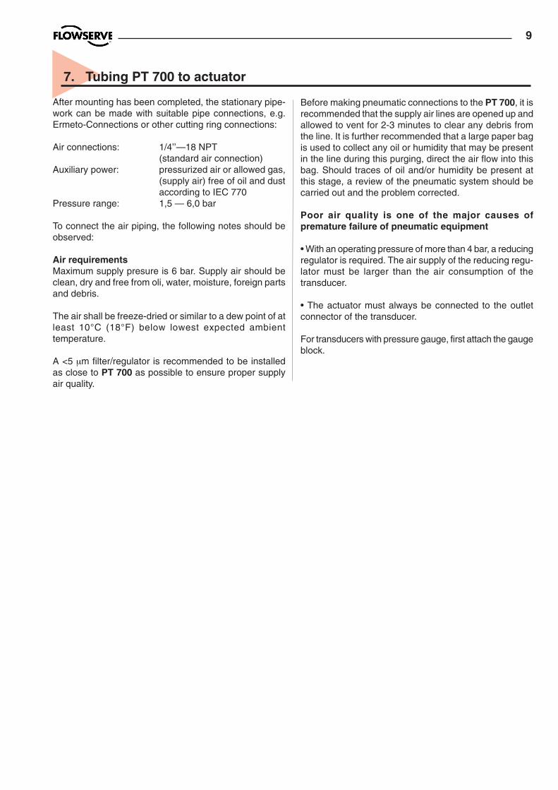
7. Tubing PT 700 to actuator
After mounting has been completed, the stationary pipe-work can be made with suitable pipe connections, e.g.Ermeto-Connections or other cutting ring connections:
Air connections: 1/4’’—18 NPT(standard air connection)
Auxiliary power: pressurized air or allowed gas,(supply air) free of oil and dustaccording to IEC 770
Pressure range: 1,5 — 6,0 bar
To connect the air piping, the following notes should beobserved:
Air requirementsMaximum supply presure is 6 bar. Supply air should beclean, dry and free from oli, water, moisture, foreign partsand debris.
The air shall be freeze-dried or similar to a dew point of atleast 10°C (18°F) below lowest expected ambienttemperature.
A <5 µm filter/regulator is recommended to be installedas close to PT 700 as possible to ensure proper supplyair quality.
Before making pneumatic connections to the PT 700, it isrecommended that the supply air lines are opened up andallowed to vent for 2-3 minutes to clear any debris fromthe line. It is further recommended that a large paper bagis used to collect any oil or humidity that may be presentin the line during this purging, direct the air flow into thisbag. Should traces of oil and/or humidity be present atthis stage, a review of the pneumatic system should becarried out and the problem corrected.
Poor air quality is one of the major causes ofpremature failure of pneumatic equipment
• With an operating pressure of more than 4 bar, a reducingregulator is required. The air supply of the reducing regu-lator must be larger than the air consumption of thetransducer.
• The actuator must always be connected to the outletconnector of the transducer.
For transducers with pressure gauge, first attach the gaugeblock.

10
8. Wiring and grounding guidelines
Electrical connections: signal cable with cable passageNPT, or M20 x 1,5) to terminals 2 x 2,5 mm
Input signal: 4 – 20 mA
• Observe the minimum requirements of voltageand equivalent electrical load:PT 700 6 VDC / 300 Ω at 20 mA
• The performance is ensured only for aminimum input current of 3,6 mA.
For wiring, the following notes should be observed:
• Absolutely observe the note CAUTION on page 3.
8.1 Grounding screwThe equipment must be grounded in accordance withthe regulations. This ground should be tied to the sameground as the electr ical conduit. For potentialcompensation via ring circuit, connect a second gro-und cable to the additional terminal provided outside.
Additionally, the electrical conduit should be earthgrounded at both ends of its run. The grounded screwmust not be used to terminate signal shield wires.
Figure 8. Connections
Connection Description+ Input +4 - 20 mA– Input –4 - 20 mA
Pneumatic outputsignal (outlet)
Air supply
8.2 Electromagnetic compatibilityThe PT 700 Electro-Pneumatic Transducer has beendesigned to operate correctly in electromagnetic (EM)fields found in typical industrial environments. Care shouldbe taken to prevent the positioner from being used inenvironments with excessively high EM field strengths(greater than 10 V/m). Portable EM devices such as hand-held two-way radios should not be used within 30 cm ofthe device.
Ensure proper wiring and shielding techniques of thecontrol lines, and route control lines away from electro-magnetic sources that may cause unwanted noise.
An electromagnetic line filter can be used to furthereliminate noise.
In the event of a severe electrostatic discharge near thepositioner, the device should be inspected to ensurecorrect operability. It may be necessary to recalibrate thePT 700 positioner to restore operation.
I t i lGrounding screws Input signal(Shielded cable)
11
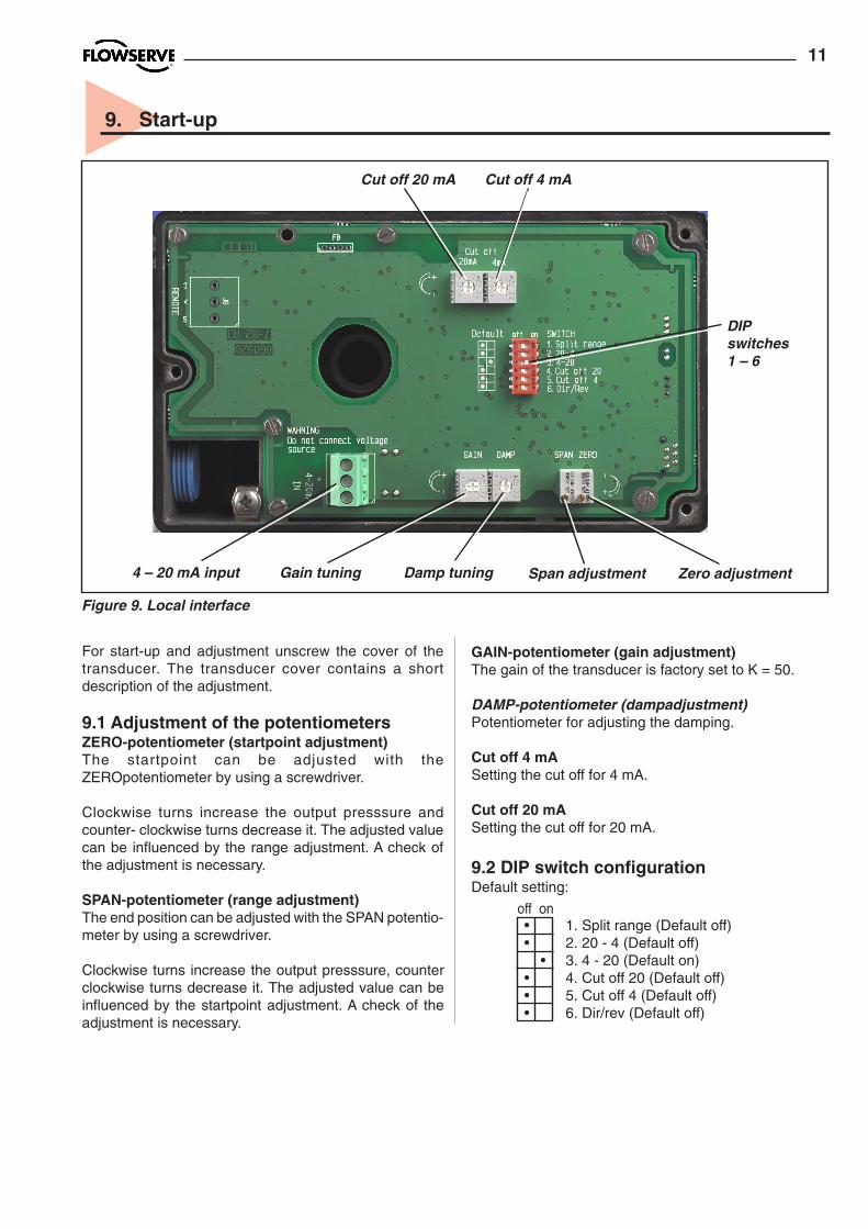
9. Start-up
For start-up and adjustment unscrew the cover of thetransducer. The transducer cover contains a shortdescription of the adjustment.
9.1 Adjustment of the potentiometersZERO-potentiometer (startpoint adjustment)The startpoint can be adjusted with theZEROpotentiometer by using a screwdriver.
Clockwise turns increase the output presssure andcounter- clockwise turns decrease it. The adjusted valuecan be influenced by the range adjustment. A check ofthe adjustment is necessary.
SPAN-potentiometer (range adjustment)The end position can be adjusted with the SPAN potentio-meter by using a screwdriver.
Clockwise turns increase the output presssure, counterclockwise turns decrease it. The adjusted value can beinfluenced by the startpoint adjustment. A check of theadjustment is necessary.
GAIN-potentiometer (gain adjustment)The gain of the transducer is factory set to K = 50.
DAMP-potentiometer (dampadjustment)Potentiometer for adjusting the damping.
Cut off 4 mASetting the cut off for 4 mA.
Cut off 20 mASetting the cut off for 20 mA.
9.2 DIP switch configurationDefault setting:
Span adjustment Zero adjustmentGain tuning Damp tuning4 – 20 mA input
DIPswitches1 – 6
Cut off 20 mA Cut off 4 mA
• 1. Split range (Default off)• 2. 20 - 4 (Default off) • 3. 4 - 20 (Default on)• 4. Cut off 20 (Default off)• 5. Cut off 4 (Default off)• 6. Dir/rev (Default off)
Figure 9. Local interface
off on
12
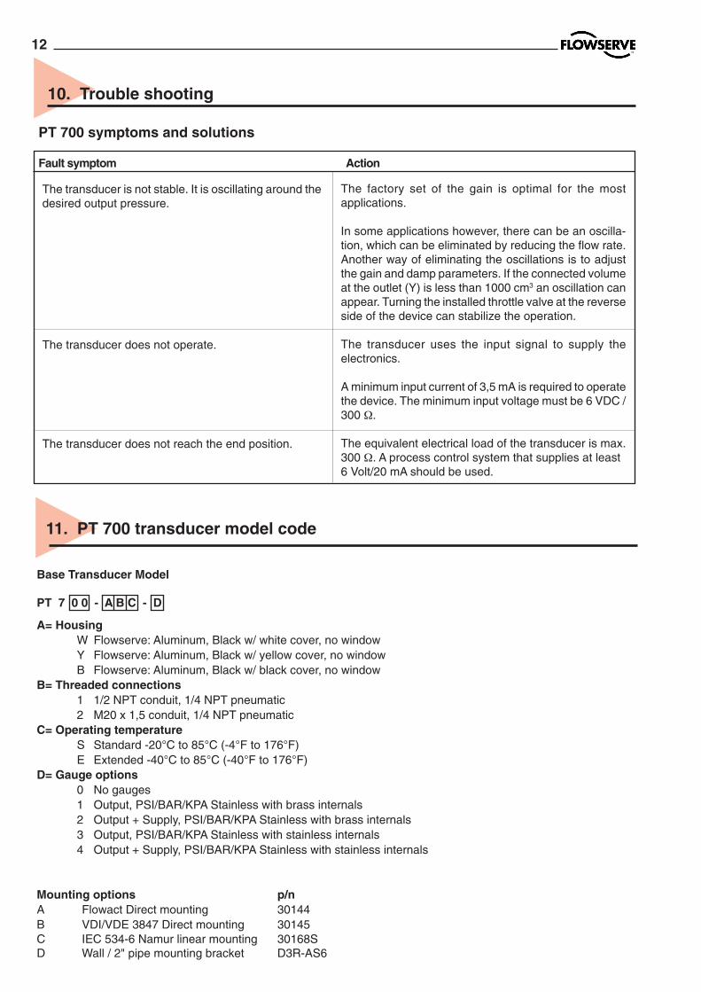
11. PT 700 transducer model code
Base Transducer Model
PT 7 0 0 - A B C - D
A= HousingW Flowserve: Aluminum, Black w/ white cover, no windowY Flowserve: Aluminum, Black w/ yellow cover, no windowB Flowserve: Aluminum, Black w/ black cover, no window
B= Threaded connections1 1/2 NPT conduit, 1/4 NPT pneumatic2 M20 x 1,5 conduit, 1/4 NPT pneumatic
C= Operating temperatureS Standard -20°C to 85°C (-4°F to 176°F)E Extended -40°C to 85°C (-40°F to 176°F)
D= Gauge options0 No gauges1 Output, PSI/BAR/KPA Stainless with brass internals2 Output + Supply, PSI/BAR/KPA Stainless with brass internals3 Output, PSI/BAR/KPA Stainless with stainless internals4 Output + Supply, PSI/BAR/KPA Stainless with stainless internals
Mounting options p/nA Flowact Direct mounting 30144B VDI/VDE 3847 Direct mounting 30145C IEC 534-6 Namur linear mounting 30168SD Wall / 2" pipe mounting bracket D3R-AS6
10. Trouble shooting
PT 700 symptoms and solutions
Fault symptom Action
The transducer is not stable. It is oscillating around thedesired output pressure.
The transducer does not operate.
The transducer does not reach the end position.
The factory set of the gain is optimal for the mostapplications.
In some applications however, there can be an oscilla-tion, which can be eliminated by reducing the flow rate.Another way of eliminating the oscillations is to adjustthe gain and damp parameters. If the connected volumeat the outlet (Y) is less than 1000 cm3 an oscillation canappear. Turning the installed throttle valve at the reverseside of the device can stabilize the operation.
The transducer uses the input signal to supply theelectronics.
A minimum input current of 3,5 mA is required to operatethe device. The minimum input voltage must be 6 VDC /300 Ω.
The equivalent electrical load of the transducer is max.300 Ω. A process control system that supplies at least6 Volt/20 mA should be used.

13
Pos. PMV P/N Description Remarks
1 Housing N/A 2 Presure sensor assembly 3 D2-SP50 STD Air relay assy. incl. O-rings, screws, standard temp. 3 D2-SP50 LT Air relay assy. incl. O-rings, screws, low temp. 4 7-SP82 Electronic module, PCB PT 700 4 7-SP82-I Electronic module, PCB, Intrinsically safe PT 715 EEx ia 5 7-SP25W Front cover, no indicator, white, incl. screws 5 7-SP25B Front cover, no indicator, black, incl. screws 6 ?? 30737 ?? Seal and O-ring kit 7 ?? 30135 ?? Screw and washer kit 8 D2-SP40GB0 Gauge block B 1/4"NPT, 1/4"NPT, 1/8"NPT, no gauges 8 D2-SP40GC0 Gauge block C 1/4"NPT, 1/4"NPT, 1/8"G, no gauges 8 D2-SP40GB1 Gauge block B 1/4"NPT, 1/4"NPT, 1/8"NPT, 1 gauge (SS/brass) 8 D2-SP40GC1 Gauge block C 1/4"NPT, 1/4"NPT, 1/8"G, 1 gauge (SS/brass) 8 D2-SP40GB2 Gauge block B 1/4"NPT, 1/4"NPT, 1/8"NPT, 2 gauges (SS/brass) 8 D2-SP40GC2 Gauge block C 1/4"NPT, 1/4"NPT, 1/8"G, 2 gauges (SS/brass) 8 D2-SP40GB3 Gauge block B 1/4"NPT, 1/4"NPT, 1/8"NPT, 1 gauge (SS/SS) 8 D2-SP40GC3 Gauge block C 1/4"NPT, 1/4"NPT, 1/8"G, 1 gauge (SS/SS) 8 D2-SP40GB4 Gauge block B 1/4"NPT, 1/4"NPT, 1/8"NPT, 2 gauges (SS/SS) 8 D2-SP40GC4 Gauge block C 1/4"NPT, 1/4"NPT, 1/8"G, 2 gauges (SS/SS) 9 30144 FlowAct mounting kit incl. O-rings, screws10 30145 VDI/VDE 3847 mounting assy. incl. O-rings, screws
12. Spare parts
5
8
10
9 1
7
4
6
3
2

FlowserveManderscheidtstrasse 1945141 EssenGERMANYTel: +49 (0) 201 8919 5Fax: +49 (0) 201 8919 662
Flowserve12, av. du Québec91965 Courtaboeuf CedexFRANCETel: +33 (0) 1 60 923 251Fax: +33 (0) 1 60 923 299
FlowserveVan Leeuvenhoekweg 63225 LX HellevoetsluisTHE NETHERLANDSTel: +31 (0) 181330044Fax: +31 (0) 181330040
FlowserveKassernengasse 69500 VillachAUSTRIATel: +43 (0) 424241 181-0Fax: +43 (0) 424241 181 50/51
FlowserveAllee du Quartz 1CH-2300 La-Chaux-deFondsSWITZERLANDTel: +41 (0) 32 925 9700Fax: +41 (0) 32 926 5422
FlowserveVia Prealpi, 30Cormano (Milano)ITALYTel: +39 (0) 2663251Fax: +39 (0) 26151863
FlowserveAv. Dr. Antunes Guimaraes1159Porto 4100-082PORTUGALTel: +351 22 619 8770Fax: +351 22 619 7575
Flowserve1350 N. Mt. Springs Prkwy.Springville, UT 84663USATel: +1 801 489 8611Fax: +1 801 489 3719
FlowservePost box 9279Edenglen 1613SOUTH AFRICATel: +27 11 923 7300Fax: +27 11 974 6127
Flowserve12 Tuas Avenue 20REPUBLIC OFSINGAPORE 638824Tel: +65 862 3332Fax: +65 862 4940
FlowserveC/O Saleh &Abdulaziz AbahsainP.O. Box 209Al Khobar 31952SAUDI ARABIATel: 9663 857 3442Fax: 9663 859 5284
Palmstierna International ABKorta Gatan 9SE-171 54 SolnaSWEDENTel:+46 (0) 8 555 106 00Fax: +46 (0) 8 555 106 01E-mail: [email protected]: www.flowserve.com
DS-
kons
ult
PM
V p
/n: 3
1857
07/
01