Pt. 23 14 CFR Ch. I (1–1–11 Edition) · 182 Pt. 23 14 CFR Ch. I (1–1–11 Edition) (c)...
178
182 14 CFR Ch. I (1–1–11 Edition) Pt. 23 (c) Changes by persons other than the manu- facturer. No design change by any person (other than the manufacturer who provided the statement of conformance for the arti- cle) is eligible for approval under this part unless the person seeking the approval is a manufacturer and applies under § 21.603(a) for a separate TSO authorization. Persons other than a manufacturer may obtain approval for design changes under part 43 or under the applicable airworthiness regulations of this chapter. § 21.620 Changes in quality system. After the issuance of a TSO authoriza- tion— (a) Each change to the quality system is subject to review by the FAA; and (b) The holder of the TSO authorization must immediately notify the FAA, in writ- ing, of any change that may affect the in- spection, conformity, or airworthiness of its article. § 21.621 Issuance of letters of TSO design approval: import articles. (a) The FAA may issue a letter of TSO de- sign approval for an article— (1) Designed and manufactured in a foreign country or jurisdiction subject to the export provisions of an agreement with the United States for the acceptance of these articles for import; and (2) For import into the United States if— (i) The State of Design certifies that the article has been examined, tested, and found to meet the applicable TSO or the applicable performance standards of the State of Design and any other performance standards the FAA may prescribe to provide a level of safe- ty equivalent to that provided by the TSO; and (ii) The manufacturer has provided to the FAA one copy of the technical data required in the applicable performance standard through its State of Design. (b) The FAA issues the letter of TSO de- sign approval that lists any deviation grant- ed under § 21.618. PART 23—AIRWORTHINESS STAND- ARDS: NORMAL, UTILITY, ACRO- BATIC, AND COMMUTER CAT- EGORY AIRPLANES SPECIAL FEDERAL AVIATION REGULATION NO. 23 Subpart A—General Sec. 23.1 Applicability. 23.2 Special retroactive requirements. 23.3 Airplane categories. Subpart B—Flight GENERAL 23.21 Proof of compliance. 23.23 Load distribution limits. 23.25 Weight limits. 23.29 Empty weight and corresponding cen- ter of gravity. 23.31 Removable ballast. 23.33 Propeller speed and pitch limits. PERFORMANCE 23.45 General. 23.49 Stalling period. 23.51 Takeoff speeds. 23.53 Takeoff performance. 23.55 Accelerate-stop distance. 23.57 Takeoff path. 23.59 Takeoff distance and takeoff run. 23.61 Takeoff flight path. 23.63 Climb: General. 23.65 Climb: All engines operating. 23.66 Takeoff climb: One-engine inoperative. 23.67 Climb: One engine inoperative. 23.69 Enroute climb/descent. 23.71 Glide: Single-engine airplanes. 23.73 Reference landing approach speed. 23.75 Landing distance. 23.77 Balked landing. FLIGHT CHARACTERISTICS 23.141 General. CONTROLLABILITY AND MANEUVERABILITY 23.143 General. 23.145 Longitudinal control. 23.147 Directional and lateral control. 23.149 Minimum control speed. 23.151 Acrobatic maneuvers. 23.153 Control during landings. 23.155 Elevator control force in maneuvers. 23.157 Rate of roll. TRIM 23.161 Trim. STABILITY 23.171 General. 23.173 Static longitudinal stability. 23.175 Demonstration of static longitudinal stability. 23.177 Static directional and lateral sta- bility. 23.181 Dynamic stability. STALLS 23.201 Wings level stall. 23.203 Turning flight and accelerated turn- ing stalls. 23.207 Stall warning. SPINNING 23.221 Spinning. VerDate Mar<15>2010 14:10 Mar 01, 2011 Jkt 223043 PO 00000 Frm 00192 Fmt 8010 Sfmt 8010 Y:\SGML\223043.XXX 223043 wwoods2 on DSK1DXX6B1PROD with CFR
Transcript of Pt. 23 14 CFR Ch. I (1–1–11 Edition) · 182 Pt. 23 14 CFR Ch. I (1–1–11 Edition) (c)...
182
14 CFR Ch. I (1–1–11 Edition) Pt. 23
(c) Changes by persons other than the manu-facturer. No design change by any person (other than the manufacturer who provided the statement of conformance for the arti-cle) is eligible for approval under this part unless the person seeking the approval is a manufacturer and applies under § 21.603(a) for a separate TSO authorization. Persons other than a manufacturer may obtain approval for design changes under part 43 or under the applicable airworthiness regulations of this chapter.
§ 21.620 Changes in quality system. After the issuance of a TSO authoriza-
tion— (a) Each change to the quality system is
subject to review by the FAA; and (b) The holder of the TSO authorization
must immediately notify the FAA, in writ-ing, of any change that may affect the in-spection, conformity, or airworthiness of its article.
§ 21.621 Issuance of letters of TSO design approval: import articles.
(a) The FAA may issue a letter of TSO de-sign approval for an article—
(1) Designed and manufactured in a foreign country or jurisdiction subject to the export provisions of an agreement with the United States for the acceptance of these articles for import; and
(2) For import into the United States if— (i) The State of Design certifies that the
article has been examined, tested, and found to meet the applicable TSO or the applicable performance standards of the State of Design and any other performance standards the FAA may prescribe to provide a level of safe-ty equivalent to that provided by the TSO; and
(ii) The manufacturer has provided to the FAA one copy of the technical data required in the applicable performance standard through its State of Design.
(b) The FAA issues the letter of TSO de-sign approval that lists any deviation grant-ed under § 21.618.
PART 23—AIRWORTHINESS STAND-ARDS: NORMAL, UTILITY, ACRO-BATIC, AND COMMUTER CAT-EGORY AIRPLANES
SPECIAL FEDERAL AVIATION REGULATION NO. 23
Subpart A—General
Sec. 23.1 Applicability. 23.2 Special retroactive requirements. 23.3 Airplane categories.
Subpart B—Flight
GENERAL
23.21 Proof of compliance. 23.23 Load distribution limits. 23.25 Weight limits. 23.29 Empty weight and corresponding cen-
ter of gravity. 23.31 Removable ballast. 23.33 Propeller speed and pitch limits.
PERFORMANCE
23.45 General. 23.49 Stalling period. 23.51 Takeoff speeds. 23.53 Takeoff performance. 23.55 Accelerate-stop distance. 23.57 Takeoff path. 23.59 Takeoff distance and takeoff run. 23.61 Takeoff flight path. 23.63 Climb: General. 23.65 Climb: All engines operating. 23.66 Takeoff climb: One-engine inoperative. 23.67 Climb: One engine inoperative. 23.69 Enroute climb/descent. 23.71 Glide: Single-engine airplanes. 23.73 Reference landing approach speed. 23.75 Landing distance. 23.77 Balked landing.
FLIGHT CHARACTERISTICS
23.141 General.
CONTROLLABILITY AND MANEUVERABILITY
23.143 General. 23.145 Longitudinal control. 23.147 Directional and lateral control. 23.149 Minimum control speed. 23.151 Acrobatic maneuvers. 23.153 Control during landings. 23.155 Elevator control force in maneuvers. 23.157 Rate of roll.
TRIM
23.161 Trim.
STABILITY
23.171 General. 23.173 Static longitudinal stability. 23.175 Demonstration of static longitudinal
stability. 23.177 Static directional and lateral sta-
bility. 23.181 Dynamic stability.
STALLS
23.201 Wings level stall. 23.203 Turning flight and accelerated turn-
ing stalls. 23.207 Stall warning.
SPINNING
23.221 Spinning.
VerDate Mar<15>2010 14:10 Mar 01, 2011 Jkt 223043 PO 00000 Frm 00192 Fmt 8010 Sfmt 8010 Y:\SGML\223043.XXX 223043ww
oods
2 on
DS
K1D
XX
6B1P
RO
D w
ith C
FR

183
Federal Aviation Administration, DOT Pt. 23
GROUND AND WATER HANDLING CHARACTERISTICS
23.231 Longitudinal stability and control. 23.233 Directional stability and control. 23.235 Operation on unpaved surfaces. 23.237 Operation on water. 23.239 Spray characteristics.
MISCELLANEOUS FLIGHT REQUIREMENTS
23.251 Vibration and buffeting. 23.253 High speed characteristics.
Subpart C—Structure
GENERAL
23.301 Loads. 23.302 Canard or tandem wing configura-
tions. 23.303 Factor of safety. 23.305 Strength and deformation. 23.307 Proof of structure.
FLIGHT LOADS
23.321 General. 23.331 Symmetrical flight conditions. 23.333 Flight envelope. 23.335 Design airspeeds. 23.337 Limit maneuvering load factors. 23.341 Gust loads factors. 23.343 Design fuel loads. 23.345 High lift devices. 23.347 Unsymmetrical flight conditions. 23.349 Rolling conditions. 23.351 Yawing conditions. 23.361 Engine torque. 23.363 Side load on engine mount. 23.365 Pressurized cabin loads. 23.367 Unsymmetrical loads due to engine
failure. 23.369 Rear lift truss. 23.371 Gyroscopic and aerodynamic loads. 23.373 Speed control devices.
CONTROL SURFACE AND SYSTEM LOADS
23.391 Control surface loads. 23.393 Loads parallel to hinge line. 23.395 Control system loads. 23.397 Limit control forces and torques. 23.399 Dual control system. 23.405 Secondary control system. 23.407 Trim tab effects. 23.409 Tabs. 23.415 Ground gust conditions.
HORIZONTAL STABILIZING AND BALANCING SURFACES
23.421 Balancing loads. 23.423 Maneuvering loads. 23.425 Gust loads. 23.427 Unsymmetrical loads.
VERTICAL SURFACES
23.441 Maneuvering loads. 23.443 Gust loads. 23.445 Outboard fins or winglets.
AILERONS AND SPECIAL DEVICES
23.455 Ailerons. 23.459 Special devices.
GROUND LOADS
23.471 General. 23.473 Ground load conditions and assump-
tions. 23.477 Landing gear arrangement. 23.479 Level landing conditions. 23.481 Tail down landing conditions. 23.483 One-wheel landing conditions. 23.485 Side load conditions. 23.493 Braked roll conditions. 23.497 Supplementary conditions for tail
wheels. 23.499 Supplementary conditions for nose
wheels. 23.505 Supplementary conditions for ski-
planes. 23.507 Jacking loads. 23.509 Towing loads. 23.511 Ground load; unsymmetrical loads on
multiple-wheel units.
WATER LOADS
23.521 Water load conditions. 23.523 Design weights and center of gravity
positions. 23.525 Application of loads. 23.527 Hull and main float load factors. 23.529 Hull and main float landing condi-
tions. 23.531 Hull and main float takeoff condi-
tion. 23.533 Hull and main float bottom pressures. 23.535 Auxiliary float loads. 23.537 Seawing loads.
EMERGENCY LANDING CONDITIONS
23.561 General. 23.562 Emergency landing dynamic condi-
tions.
FATIGUE EVALUATION
23.571 Metallic pressurized cabin structures. 23.572 Metallic wing, empennage, and asso-
ciated structures. 23.573 Damage tolerance and fatigue evalua-
tion of structure. 23.574 Metallic damage tolerance and fa-
tigue evaluation of commuter category airplanes.
23.575 Inspections and other procedures.
Subpart D—Design and Construction
23.601 General. 23.603 Materials and workmanship. 23.605 Fabrication methods. 23.607 Fasteners. 23.609 Protection of structure. 23.611 Accessibility provisions. 23.613 Material strength properties and de-
sign values. 23.619 Special factors.
VerDate Mar<15>2010 14:10 Mar 01, 2011 Jkt 223043 PO 00000 Frm 00193 Fmt 8010 Sfmt 8010 Y:\SGML\223043.XXX 223043ww
oods
2 on
DS
K1D
XX
6B1P
RO
D w
ith C
FR

184
14 CFR Ch. I (1–1–11 Edition) Pt. 23
23.621 Casting factors. 23.623 Bearing factors. 23.625 Fitting factors. 23.627 Fatigue strength. 23.629 Flutter.
WINGS
23.641 Proof of strength.
CONTROL SURFACES
23.651 Proof of strength. 23.655 Installation. 23.657 Hinges. 23.659 Mass balance.
CONTROL SYSTEMS
23.671 General. 23.672 Stability augmentation and auto-
matic and power-operated systems. 23.673 Primary flight controls. 23.675 Stops. 23.677 Trim systems. 23.679 Control system locks. 23.681 Limit load static tests. 23.683 Operation tests. 23.685 Control system details. 23.687 Spring devices. 23.689 Cable systems. 23.691 Artificial stall barrier system. 23.693 Joints. 23.697 Wing flap controls. 23.699 Wing flap position indicator. 23.701 Flap interconnection. 23.703 Takeoff warning system.
LANDING GEAR
23.721 General. 23.723 Shock absorption tests. 23.725 Limit drop tests. 23.726 Ground load dynamic tests. 23.727 Reserve energy absorption drop test. 23.729 Landing gear extension and retrac-
tion system. 23.731 Wheels. 23.733 Tires. 23.735 Brakes. 23.737 Skis. 23.745 Nose/tail wheel steering.
FLOATS AND HULLS
23.751 Main float buoyancy. 23.753 Main float design. 23.755 Hulls. 23.757 Auxiliary floats.
PERSONNEL AND CARGO ACCOMMODATIONS
23.771 Pilot compartment. 23.773 Pilot compartment view. 23.775 Windshields and windows. 23.777 Cockpit controls. 23.779 Motion and effect of cockpit controls. 23.781 Cockpit control knob shape. 23.783 Doors. 23.785 Seats, berths, litters, safety belts,
and shoulder harnesses.
23.787 Baggage and cargo compartments. 23.791 Passenger information signs. 23.803 Emergency evacuation. 23.805 Flightcrew emergency exits. 23.807 Emergency exits. 23.811 Emergency exit marking. 23.812 Emergency lighting. 23.813 Emergency exit access. 23.815 Width of aisle. 23.831 Ventilation.
PRESSURIZATION
23.841 Pressurized cabins. 23.843 Pressurization tests.
FIRE PROTECTION
23.851 Fire extinguishers. 23.853 Passenger and crew compartment in-
teriors. 23.855 Cargo and baggage compartment fire
protection. 23.859 Combustion heater fire protection. 23.863 Flammable fluid fire protection. 23.865 Fire protection of flight controls, en-
gine mounts, and other flight structure.
ELECTRICAL BONDING AND LIGHTNING PROTECTION
23.867 Electrical bonding and protection against lightning and static electricity.
MISCELLANEOUS
23.871 Leveling means.
Subpart E—Powerplant
GENERAL
23.901 Installation. 23.903 Engines. 23.904 Automatic power reserve system. 23.905 Propellers. 23.907 Propeller vibration and fatigue. 23.909 Turbocharger systems. 23.925 Propeller clearance. 23.929 Engine installation ice protection. 23.933 Reversing systems. 23.934 Turbojet and turbofan engine thrust
reverser systems tests. 23.937 Turbopropeller-drag limiting sys-
tems. 23.939 Powerplant operating characteristics. 23.943 Negative acceleration.
FUEL SYSTEM
23.951 General. 23.953 Fuel system independence. 23.954 Fuel system lightning protection. 23.955 Fuel flow. 23.957 Flow between interconnected tanks. 23.959 Unusable fuel supply. 23.961 Fuel system hot weather operation. 23.963 Fuel tanks: General. 23.965 Fuel tank tests. 23.967 Fuel tank installation. 23.969 Fuel tank expansion space.
VerDate Mar<15>2010 14:10 Mar 01, 2011 Jkt 223043 PO 00000 Frm 00194 Fmt 8010 Sfmt 8010 Y:\SGML\223043.XXX 223043ww
oods
2 on
DS
K1D
XX
6B1P
RO
D w
ith C
FR

185
Federal Aviation Administration, DOT Pt. 23
23.971 Fuel tank sump. 23.973 Fuel tank filler connection. 23.975 Fuel tank vents and carburetor vapor
vents. 23.977 Fuel tank outlet. 23.979 Pressure fueling systems.
FUEL SYSTEM COMPONENTS
23.991 Fuel pumps. 23.993 Fuel system lines and fittings. 23.994 Fuel system components. 23.995 Fuel valves and controls. 23.997 Fuel strainer or filter. 23.999 Fuel system drains. 23.1001 Fuel jettisoning system.
OIL SYSTEM
23.1011 General. 23.1013 Oil tanks. 23.1015 Oil tank tests. 23.1017 Oil lines and fittings. 23.1019 Oil strainer or filter. 23.1021 Oil system drains. 23.1023 Oil radiators. 23.1027 Propeller feathering system.
COOLING
23.1041 General. 23.1043 Cooling tests. 23.1045 Cooling test procedures for turbine
engine powered airplanes. 23.1047 Cooling test procedures for recipro-
cating engine powered airplanes.
LIQUID COOLING
23.1061 Installation. 23.1063 Coolant tank tests.
INDUCTION SYSTEM
23.1091 Air induction system. 23.1093 Induction system icing protection. 23.1095 Carburetor deicing fluid flow rate. 23.1097 Carburetor deicing fluid system ca-
pacity. 23.1099 Carburetor deicing fluid system de-
tail design. 23.1101 Induction air preheater design. 23.1103 Induction system ducts. 23.1105 Induction system screens. 23.1107 Induction system filters. 23.1109 Turbocharger bleed air system. 23.1111 Turbine engine bleed air system.
EXHAUST SYSTEM
23.1121 General. 23.1123 Exhaust system. 23.1125 Exhaust heat exchangers.
POWERPLANT CONTROLS AND ACCESSORIES
23.1141 Powerplant controls: General. 23.1142 Auxiliary power unit controls. 23.1143 Engine controls. 23.1145 Ignition switches. 23.1147 Mixture controls. 23.1149 Propeller speed and pitch controls.
23.1153 Propeller feathering controls. 23.1155 Turbine engine reverse thrust and
propeller pitch settings below the flight regime.
23.1157 Carburetor air temperature controls. 23.1163 Powerplant accessories. 23.1165 Engine ignition systems.
POWERPLANT FIRE PROTECTION
23.1181 Designated fire zones; regions in-cluded.
23.1182 Nacelle areas behind firewalls. 23.1183 Lines, fittings, and components. 23.1189 Shutoff means. 23.1191 Firewalls. 23.1192 Engine accessory compartment dia-
phragm. 23.1193 Cowling and nacelle. 23.1195 Fire extinguishing systems. 23.1197 Fire extinguishing agents. 23.1199 Extinguishing agent containers. 23.1201 Fire extinguishing systems mate-
rials. 23.1203 Fire detector system.
Subpart F—Equipment
GENERAL
23.1301 Function and installation. 23.1303 Flight and navigation instruments. 23.1305 Powerplant instruments. 23.1307 Miscellaneous equipment. 23.1308 High-intensity Radiated Fields
(HIRF) Protection. 23.1309 Equipment, systems, and installa-
tions.
INSTRUMENTS: INSTALLATION
23.1311 Electronic display instrument sys-tems.
23.1321 Arrangement and visibility. 23.1322 Warning, caution, and advisory
lights. 23.1323 Airspeed indicating system. 23.1325 Static pressure system. 23.1326 Pitot heat indication systems. 23.1327 Magnetic direction indicator. 23.1329 Automatic pilot system. 23.1331 Instruments using a power source. 23.1335 Flight director systems. 23.1337 Powerplant instruments installa-
tion.
ELECTRICAL SYSTEMS AND EQUIPMENT
23.1351 General. 23.1353 Storage battery design and installa-
tion. 23.1357 Circuit protective devices. 23.1359 Electrical system fire protection. 23.1361 Master switch arrangement. 23.1365 Electric cables and equipment. 23.1367 Switches.
LIGHTS
23.1381 Instrument lights. 23.1383 Taxi and landing lights.
VerDate Mar<15>2010 14:10 Mar 01, 2011 Jkt 223043 PO 00000 Frm 00195 Fmt 8010 Sfmt 8010 Y:\SGML\223043.XXX 223043ww
oods
2 on
DS
K1D
XX
6B1P
RO
D w
ith C
FR
186
14 CFR Ch. I (1–1–11 Edition) Pt. 23, SFAR No. 23
23.1385 Position light system installation. 23.1387 Position light system dihedral an-
gles. 23.1389 Position light distribution and in-
tensities. 23.1391 Minimum intensities in the hori-
zontal plane of position lights. 23.1393 Minimum intensities in any vertical
plane of position lights. 23.1395 Maximum intensities in overlapping
beams of position lights. 23.1397 Color specifications. 23.1399 Riding light. 23.1401 Anticollision light system.
SAFETY EQUIPMENT
23.1411 General. 23.1415 Ditching equipment. 23.1416 Pneumatic de-icer boot system. 23.1419 Ice protection.
MISCELLANEOUS EQUIPMENT
23.1431 Electronic equipment. 23.1435 Hydraulic systems. 23.1437 Accessories for multiengine air-
planes. 23.1438 Pressurization and pneumatic sys-
tems. 23.1441 Oxygen equipment and supply. 23.1443 Minimum mass flow of supplemental
oxygen. 23.1445 Oxygen distribution system. 23.1447 Equipment standards for oxygen dis-
pensing units. 23.1449 Means for determining use of oxy-
gen. 23.1450 Chemical oxygen generators. 23.1451 Fire protection for oxygen equip-
ment. 23.1453 Protection of oxygen equipment
from rupture. 23.1457 Cockpit voice recorders. 23.1459 Flight data recorders. 23.1461 Equipment containing high energy
rotors.
Subpart G—Operating Limitations and Information
23.1501 General. 23.1505 Airspeed limitations. 23.1507 Operating maneuvering speed. 23.1511 Flap extended speed. 23.1513 Minimum control speed. 23.1519 Weight and center of gravity. 23.1521 Powerplant limitations. 23.1522 Auxiliary power unit limitations. 23.1523 Minimum flight crew. 23.1524 Maximum passenger seating configu-
ration. 23.1525 Kinds of operation. 23.1527 Maximum operating altitude. 23.1529 Instructions for Continued Air-
worthiness.
MARKINGS AND PLACARDS
23.1541 General.
23.1543 Instrument markings: General. 23.1545 Airspeed indicator. 23.1547 Magnetic direction indicator. 23.1549 Powerplant and auxiliary power unit
instruments. 23.1551 Oil quantity indicator. 23.1553 Fuel quantity indicator. 23.1555 Control markings. 23.1557 Miscellaneous markings and plac-
ards. 23.1559 Operating limitations placard. 23.1561 Safety equipment. 23.1563 Airspeed placards. 23.1567 Flight maneuver placard.
AIRPLANE FLIGHT MANUAL AND APPROVED MANUAL MATERIAL
23.1581 General. 23.1583 Operating limitations. 23.1585 Operating procedures. 23.1587 Performance information. 23.1589 Loading information. APPENDIX A TO PART 23—SIMPLIFIED DESIGN
LOAD CRITERIA APPENDIX B TO PART 23 [RESERVED] APPENDIX C TO PART 23—BASIC LANDING CON-
DITIONS APPENDIX D TO PART 23—WHEEL SPIN-UP AND
SPRING-BACK LOADS APPENDIX E TO PART 23 [RESERVED] APPENDIX F TO PART 23—TEST PROCEDURE APPENDIX G TO PART 23—INSTRUCTIONS FOR
CONTINUED AIRWORTHINESS APPENDIX H TO PART 23—INSTALLATION OF AN
AUTOMATIC POWER RESERVE (APR) SYS-TEM
APPENDIX I TO PART 23—SEAPLANE LOADS APPENDIX J TO PART 23—HIRF ENVIRONMENTS
AND EQUIPMENT HIRF TEST LEVELS
AUTHORITY: 49 U.S.C. 106(g), 40113, 44701– 44702, 44704.
SOURCE: Docket No. 4080, 29 FR 17955, Dec. 18. 1964; 30 FR 258, Jan. 9, 1965, unless other-wise noted.
SPECIAL FEDERAL AVIATION REGULATION NO. 23
1. Applicability. An applicant is entitled to a type certificate in the normal category for a reciprocating or turbopropeller multien-gine powered small airplane that is to be cer-tificated to carry more than 10 occupants and that is intended for use in operations under Part 135 of the Federal Aviation Regu-lations if he shows compliance with the ap-plicable requirements of Part 23 of the Fed-eral Aviation Regulations, as supplemented or modified by the additional airworthiness requirements of this regulation.
2. References. Unless otherwise provided, all references in this regulation to specific sec-tions of Part 23 of the Federal Aviation Reg-ulations are those sections of Part 23 in ef-fect on March 30, 1967.
VerDate Mar<15>2010 14:10 Mar 01, 2011 Jkt 223043 PO 00000 Frm 00196 Fmt 8010 Sfmt 8002 Y:\SGML\223043.XXX 223043ww
oods
2 on
DS
K1D
XX
6B1P
RO
D w
ith C
FR
187
Federal Aviation Administration, DOT Pt. 23, SFAR No. 23
FLIGHT REQUIREMENTS
3. General. Compliance must be shown with the applicable requirements of Subpart B of Part 23 of the Federal Aviation Regulations in effect on March 30, 1967, as supplemented or modified in sections 4 through 10 of this regulation.
PERFORMANCE
4. General. (a) Unless otherwise prescribed in this regulation, compliance with each ap-plicable performance requirement in sections 4 through 7 of this regulation must be shown for ambient atmospheric conditions and still air.
(b) The performance must correspond to the propulsive thrust available under the particular ambient atmospheric conditions and the particular flight condition. The available propulsive thrust must correspond to engine power or thrust, not exceeding the approved power or thrust less—
(1) Installation losses; and (2) The power or equivalent thrust ab-
sorbed by the accessories and services appro-priate to the particular ambient atmospheric conditions and the particular flight condi-tion.
(c) Unless otherwise prescribed in this reg-ulation, the applicant must select the take- off, en route, and landing configurations for the airplane.
(d) The airplane configuration may vary with weight, altitude, and temperature, to the extent they are compatible with the op-erating procedures required by paragraph (e) of this section.
(e) Unless otherwise prescribed in this reg-ulation, in determining the critical engine inoperative takeoff performance, the accel-erate-stop distance, takeoff distance, changes in the airplane’s configuration, speed, power, and thrust, must be made in accordance with procedures established by the applicant for operation in service.
(f) Procedures for the execution of balked landings must be established by the appli-cant and included in the Airplane Flight Manual.
(g) The procedures established under para-graphs (e) and (f) of this section must—
(1) Be able to be consistently executed in service by a crew of average skill;
(2) Use methods or devices that are safe and reliable; and
(3) Include allowance for any time delays, in the execution of the procedures, that may reasonably be expected in service.
5. Takeoff—(a) General. The takeoff speeds described in paragraph (b), the accelerate- stop distance described in paragraph (c), and the takeoff distance described in paragraph (d), must be determined for—
(1) Each weight, altitude, and ambient temperature within the operational limits selected by the applicant;
(2) The selected configuration for takeoff; (3) The center of gravity in the most unfa-
vorable position; (4) The operating engine within approved
operating limitation; and (5) Takeoff data based on smooth, dry,
hard-surface runway. (b) Takeoff speeds. (1) The decision speed V1
is the calibrated airspeed on the ground at which, as a result of engine failure or other reasons, the pilot is assumed to have made a decision to continue or discontinue the take-off. The speed V1 must be selected by the ap-plicant but may not be less than—
(i) 1.10 Vs1; (ii) 1.10 VMC; (iii) A speed that permits acceleration to
V1 and stop in accordance with paragraph (c) allowing credit for an overrun distance equal to that required to stop the airplane from a ground speed of 35 knots utilizing maximum braking; or
(iv) A speed at which the airplane can be rotated for takeoff and shown to be adequate to safely continue the takeoff, using normal piloting skill, when the critical engine is suddenly made inoperative.
(2) Other essential takeoff speeds necessary for safe operation of the airplane must be de-termined and shown in the Airplane Flight Manual.
(c) Accelerate-stop distance. (1) The accel-erate-stop distance is the sum of the dis-tances necessary to—
(i) Accelerate the airplane from a standing start to V1; and
(ii) Decelerate the airplane from V1 to a speed not greater than 35 knots, assuming that in the case of engine failure, failure of the critical engine is recognized by the pilot at the speed V1. The landing gear must re-main in the extended position and maximum braking may be utilized during deceleration.
(2) Means other than wheel brakes may be used to determine the accelerate-stop dis-tance if that means is available with the critical engine inoperative and—
(i) Is safe and reliable; (ii) Is used so that consistent results can
be expected under normal operating condi-tions; and
(iii) Is such that exceptional skill is not re-quired to control the airplane.
(d) All engines operating takeoff distance. The all engine operating takeoff distance is the horizontal distance required to takeoff and climb to a height of 50 feet above the takeoff surface according to procedures in FAR 23.51(a).
(e) One-engine-inoperative takeoff. The max-imum weight must be determined for each altitude and temperature within the oper-ational limits established for the airplane, at which the airplane has takeoff capability after failure of the critical engine at or above V1 determined in accordance with
VerDate Mar<15>2010 14:10 Mar 01, 2011 Jkt 223043 PO 00000 Frm 00197 Fmt 8010 Sfmt 8002 Y:\SGML\223043.XXX 223043ww
oods
2 on
DS
K1D
XX
6B1P
RO
D w
ith C
FR
188
14 CFR Ch. I (1–1–11 Edition) Pt. 23, SFAR No. 23
paragraph (b) of this section. This capability may be established—
(1) By demonstrating a measurably posi-tive rate of climb with the airplane in the takeoff configuration, landing gear extended; or
(2) By demonstrating the capability of maintaining flight after engine failure uti-lizing procedures prescribed by the appli-cant.
6. Climb—(a) Landing climb: All-engines-oper-ating. The maximum weight must be deter-mined with the airplane in the landing con-figuration, for each altitude, and ambient temperature within the operational limits established for the airplane and with the most unfavorable center of gravity and out- of-ground effect in free air, at which the steady gradient of climb will not be less than 3.3 percent, with:
(1) The engines at the power that is avail-able 8 seconds after initiation of movement of the power or thrust controls from the mimimum flight idle to the takeoff position.
(2) A climb speed not greater than the ap-proach speed established under section 7 of this regulation and not less than the greater of 1.05MC or 1.10VS1.
(b) En route climb, one-engine-inoperative. (1) the maximum weight must be determined with the airplane in the en route configura-tion, the critical engine inoperative, the re-maining engine at not more than maximum continuous power or thrust, and the most unfavorable center of gravity, at which the gradient at climb will be not less than—
(i) 1.2 percent (or a gradient equivalent to 0.20 Vso2, if greater) at 5,000 feet and an ambi-ent temperature of 41 °F. or
(ii) 0.6 percent (or a gradient equivalent to 0.01 Vso2, if greater) at 5,000 feet and ambient temperature of 81 °F.
(2) The minimum climb gradient specified in subdivisions (i) and (ii) of subparagraph (1) of this paragraph must vary linearly between 41 °F. and 81 °F. and must change at the same rate up to the maximum operational tem-perature approved for the airplane.
7. Landing. The landing distance must be determined for standard atmosphere at each weight and altitude in accordance with FAR 23.75(a), except that instead of the gliding ap-proach specified in FAR 23.75(a)(1), the land-ing may be preceded by a steady approach down to the 50-foot height at a gradient of descent not greater than 5.2 percent (3°) at a calibrated airspeed not less than 1.3s1.
TRIM
8. Trim—(a) Lateral and directional trim. The airplane must maintain lateral and direc-tional trim in level flight at a speed of Vh
or VMO/MMO, whichever is lower, with land-ing gear and wing flaps retracted.
(b) Longitudinal trim. The airplane must maintain longitudinal trim during the fol-lowing conditions, except that it need not
maintain trim at a speed greater than VMO/ MMO:
(1) In the approach conditions specified in FAR 23.161(c)(3) through (5), except that in-stead of the speeds specified therein, trim must be maintained with a stick force of not more than 10 pounds down to a speed used in showing compliance with section 7 of this regulation or 1.4 Vs1 whichever is lower.
(2) In level flight at any speed from VH or VMO/MMO, whichever is lower, to either Vx or 1.4 Vs1, with the landing gear and wing flaps retracted.
STABILITY
9. Static longitudinal stability. (a) In showing compliance with the provisions of FAR 23.175(b) and with paragraph (b) of this sec-tion, the airspeed must return to within ±71⁄2 percent of the trim speed.
(b) Cruise stability. The stick force curve must have a stable slope for a speed range of ±50 knots from the trim speed except that the speeds need not exceed VFC/MFC or be less than 1.4 Vs1. This speed range will be considered to begin at the outer extremes of the friction band and the stick force may not exceed 50 pounds with—
(i) Landing gear retracted; (ii) Wing flaps retracted; (iii) The maximum cruising power as se-
lected by the applicant as an operating limi-tation for turbine engines or 75 percent of maximum continuous power for recipro-cating engines except that the power need not exceed that required at VMO/MMO:
(iv) Maximum takeoff weight; and (v) The airplane trimmed for level flight
with the power specified in subparagraph (iii) of this paragraph.
VFC/MFC may not be less than a speed midway between VMO/MMO and VDF/MDF, ex-cept that, for altitudes where Mach number is the limiting factor, MFC need not exceed the Mach number at which effective speed warning occurs.
(c) Climb stability. For turbopropeller powered airplanes only. In showing compliance with FAR 23.175(a), an applicant must in lieu of the power specified in FAR 23.175(a)(4), use the maximum power or thrust selected by the applicant as an operating limitation for use during climb at the best rate of climb speed except that the speed need not be less than 1.4 Vs1.
STALLS
10. Stall warning. If artificial stall warning is required to comply with the requirements of FAR 23.207, the warning device must give clearly distinguishable indications under ex-pected conditions of flight. The use of a vis-ual warning device that requires the atten-tion of the crew within the cockpit is not ac-ceptable by itself.
VerDate Mar<15>2010 14:10 Mar 01, 2011 Jkt 223043 PO 00000 Frm 00198 Fmt 8010 Sfmt 8002 Y:\SGML\223043.XXX 223043ww
oods
2 on
DS
K1D
XX
6B1P
RO
D w
ith C
FR

189
Federal Aviation Administration, DOT Pt. 23, SFAR No. 23
CONTROL SYSTEMS
11. Electric trim tabs. The airplane must meet the requirements of FAR 23.677 and in addition it must be shown that the airplane is safely controllable and that a pilot can perform all the maneuvers and operations necessary to effect a safe landing following any probable electric trim tab runaway which might be reasonably expected in serv-ice allowing for appropriate time delay after pilot recognition of the runaway. This dem-onstration must be conducted at the critical airplane weights and center of gravity posi-tions.
INSTRUMENTS: INSTALLATION
12. Arrangement and visibility. Each instru-ment must meet the requirements of FAR 23.1321 and in addition—
(a) Each flight, navigation, and powerplant instrument for use by any pilot must be plainly visible to him from his station with the minimum practicable deviation from his normal position and line of vision when he is looking forward along the flight path.
(b) The flight instruments required by FAR 23.1303 and by the applicable operating rules must be grouped on the instrument panel and centered as nearly as practicable about the vertical plane of each pilot’s forward vi-sion. In addition—
(1) The instrument that most effectively indicates the attitude must be on the panel in the top center position;
(2) The instrument that most effectively indicates airspeed must be adjacent to and directly to the left of the instrument in the top center position;
(3) The instrument that most effectively indicates altitude must be adjacent to and directly to the right of the instrument in the top center position; and
(4) The instrument that most effectively indicates direction of flight must be adjacent to and directly below the instrument in the top center position.
13. Airspeed indicating system. Each airspeed indicating system must meet the require-ments of FAR 23.1323 and in addition—
(a) Airspeed indicating instruments must be of an approved type and must be cali-brated to indicate true airspeed at sea level in the standard atmosphere with a mimimum practicable instrument calibra-tion error when the corresponding pilot and static pressures are supplied to the instru-ments.
(b) The airspeed indicating system must be calibrated to determine the system error, i.e., the relation between IAS and CAS, in flight and during the accelerate takeoff ground run. The ground run calibration must be obtained between 0.8 of the mimimum value of V1 and 1.2 times the maximum value of V1, considering the approved ranges of al-titude and weight. The ground run calibra-
tion will be determined assuming an engine failure at the mimimum value of V1.
(c) The airspeed error of the installation excluding the instrument calibration error, must not exceed 3 percent or 5 knots which-ever is greater, throughout the speed range from VMO to 1.3S1 with flaps retracted and from 1.3 VSO to VFE with flaps in the land-ing position.
(d) Information showing the relationship between IAS and CAS must be shown in the Airplane Flight Manual.
14. Static air vent system. The static air vent system must meet the requirements of FAR 23.1325. The altimeter system calibration must be determined and shown in the Air-plane Flight Manual.
OPERATING LIMITATIONS AND INFORMATION
15. Maximum operating limit speed VMO/MMO. Instead of establishing operating limitations based on VME and VNO, the applicant must establish a maximum operating limit speed VMO/MMO in accordance with the following:
(a) The maximum operating limit speed must not exceed the design cruising speed Vc and must be sufficiently below VD/MD or VDF/MDF to make it highly improbable that the latter speeds will be inadvertently ex-ceeded in flight.
(b) The speed Vmo must not exceed 0.8 VD/ MD or 0.8 VDF/MDF unless flight dem-onstrations involving upsets as specified by the Administrator indicates a lower speed margin will not result in speeds exceeding VD/MD or VDF. Atmospheric variations, hor-izontal gusts, and equipment errors, and air-frame production variations will be taken into account.
16. Minimum flight crew. In addition to meeting the requirements of FAR 23.1523, the applicant must establish the minimum num-ber and type of qualified flight crew per-sonnel sufficient for safe operation of the airplane considering—
(a) Each kind of operation for which the applicant desires approval;
(b) The workload on each crewmember con-sidering the following:
(1) Flight path control. (2) Collision avoidance. (3) Navigation. (4) Communications. (5) Operation and monitoring of all essen-
tial aircraft systems. (6) Command decisions; and (c) The accessibility and ease of operation
of necessary controls by the appropriate crewmember during all normal and emer-gency operations when at his flight station.
17. Airspeed indicator. The airspeed indi-cator must meet the requirements of FAR 23.1545 except that, the airspeed notations and markings in terms of VNO and VNE
must be replaced by the VMO/MMO nota-tions. The airspeed indicator markings must be easily read and understood by the pilot. A
VerDate Mar<15>2010 14:10 Mar 01, 2011 Jkt 223043 PO 00000 Frm 00199 Fmt 8010 Sfmt 8002 Y:\SGML\223043.XXX 223043ww
oods
2 on
DS
K1D
XX
6B1P
RO
D w
ith C
FR
190
14 CFR Ch. I (1–1–11 Edition) Pt. 23, SFAR No. 23
placard adjacent to the airspeed indicator is an acceptable means of showing compliance with the requirements of FAR 23.1545(c).
AIRPLANE FLIGHT MANUAL
18. General. The Airplane Flight Manual must be prepared in accordance with the re-quirements of FARs 23.1583 and 23.1587, and in addition the operating limitations and performance information set forth in sec-tions 19 and 20 must be included.
19. Operating limitations. The Airplane Flight Manual must include the following limitations—
(a) Airspeed limitations. (1) The maximum operating limit speed VMO/MMO and a state-ment that this speed limit may not be delib-erately exceeded in any regime of flight (climb, cruise, or descent) unless a higher speed is authorized for flight test or pilot training;
(2) If an airspeed limitation is based upon compressibility effects, a statement to this effect and information as to any symptoms, the probable behavior of the airplane, and the recommended recovery procedures; and
(3) The airspeed limits, shown in terms of VMO/MMO instead of VNO and VNE.
(b) Takeoff weight limitations. The max-imum takeoff weight for each airport ele-vation, ambient temperature, and available takeoff runway length within the range se-lected by the applicant. This weight may not exceed the weight at which:
(1) The all-engine operating takeoff dis-tance determined in accordance with section 5(d) or the accelerate-stop distance deter-mined in accordance with section 5(c), which ever is greater, is equal to the available run-way length;
(2) The airplane complies with the one-en-gine-inoperative takeoff requirements speci-fied in section 5(e); and
(3) The airplane complies with the one-en-gine-inoperative en route climb require-ments specified in section 6(b), assuming that a standard temperature lapse rate ex-ists from the airport elevation to the alti-tude of 5,000 feet, except that the weight may not exceed that corresponding to a tempera-ture of 41 °F at 5,000 feet.
20. Performance information. The Airplane Flight Manual must contain the performance information determined in accordance with the provisions of the performance require-ments of this regulation. The information must include the following:
(a) Sufficient information so that the take- off weight limits specified in section 19(b) can be determined for all temperatures and altitudes within the operation limitations selected by the applicant.
(b) The conditions under which the per-formance information was obtained, includ-ing the airspeed at the 50-foot height used to determine landing distances.
(c) The performance information (deter-mined by extrapolation and computed for the range of weights between the maximum landing and takeoff weights) for—
(1) Climb in the landing configuration; and (2) Landing distance. (d) Procedure established under section 4 of
this regulation related to the limitations and information required by this section in the form of guidance material including any relevant limitations or information.
(e) An explanation of significant or un-usual flight or ground handling characteris-tics of the airplane.
(f) Airspeeds, as indicated airspeeds, cor-responding to those determined for takeoff in accordance with section 5(b).
21. Maximum operating altitudes. The max-imum operating altitude to which operation is permitted, as limited by flight, structural, powerplant, functional, or equipment char-acteristics, must be specified in the Airplane Flight Manual.
22. Stowage provision for Airplane Flight Manual. Provision must be made for stowing the Airplane Flight Manual in a suitable fixed container which is readily accessible to the pilot.
23. Operating procedures. Procedures for re-starting turbine engines in flight (including the effects of altitude) must be set forth in the Airplane Flight Manual.
AIRFRAME REQUIREMENTS
FLIGHT LOADS
24. Engine torque. (a) Each turbopropeller engine mount and its supporting structure must be designed for the torque effects of—
(1) The conditions set forth in FAR 23.361(a).
(2) The limit engine torque corresponding to takeoff power and propeller speed, multi-plied by a factor accounting for propeller control system malfunction, including quick feathering action, simultaneously with 1 g level flight loads. In the absence of a ration-al analysis, a factor of 1.6 must be used.
(b) The limit torque is obtained by multi-plying the mean torque by a factor of 1.25.
25. Turbine engine gyroscopic loads. Each turbopropeller engine mount and its sup-porting structure must be designed for the gyroscopic loads that result, with the en-gines at maximum continuous r.p.m., under either—
(a) The conditions prescribed in FARs 23.351 and 23.423; or
(b) All possible combinations of the fol-lowing:
(1) A yaw velocity of 2.5 radius per second. (2) A pitch velocity of 1.0 radians per sec-
ond. (3) A normal load factor of 2.5. (4) Maximum continuous thrust. 26. Unsymmetrical loads due to engine failure.
(a) Turbopropeller powered airplanes must
VerDate Mar<15>2010 14:10 Mar 01, 2011 Jkt 223043 PO 00000 Frm 00200 Fmt 8010 Sfmt 8002 Y:\SGML\223043.XXX 223043ww
oods
2 on
DS
K1D
XX
6B1P
RO
D w
ith C
FR

191
Federal Aviation Administration, DOT Pt. 23, SFAR No. 23
be designed for the unsymmetrical loads re-sulting from the failure of the critical engine including the following conditions in com-bination with a single malfunction of the propeller drag limiting system, considering the probable pilot corrective action on the flight controls.
(1) At speeds between VMC and VD, the loads resulting from power failure because of fuel flow interruption are considered to be limit loads.
(2) At speeds between VMC and VC, the loads resulting from the disconnection of the engine compressor from the turbine or from loss of the turbine blades are considered to be ultimate loads.
(3) The time history of the thrust decay and drag buildup occurring as a result of the prescribed engine failures must be substan-tiated by test or other data applicable to the particular engine-propeller combination.
(4) The timing and magnitude of the prob-able pilot corrective action must be conserv-atively estimated, considering the character-istics of the particular engine-propeller-air-plane combination.
(b) Pilot corrective action may be assumed to be initiated at the time maximum yawing velocity is reached, but not earlier than two seconds after the engine failure. The mag-nitude of the corrective action may be based on the control forces specified in FAR 23.397 except that lower forces may be assumed where it is shown by analysis or test that these forces can control the yaw and roll re-sulting from the prescribed engine failure conditions.
GROUND LOADS
27. Dual wheel landing gear units. Each dual wheel landing gear unit and its supporting structure must be shown to comply with the following:
(a) Pivoting. The airplane must be assumed to pivot about one side of the main gear with the brakes on that side locked. The limit vertical load factor must be 1.0 and the coef-ficient of friction 0.8. This condition need apply only to the main gear and its sup-porting structure.
(b) Unequal tire inflation. A 60–40 percent distribution of the loads established in ac-cordance with FAR 23.471 through FAR 23.483 must be applied to the dual wheels.
(c) Flat tire. (1) Sixty percent of the loads specified in FAR 23.471 through FAR 23.483 must be applied to either wheel in a unit.
(2) Sixty percent of the limit drag and side loads and 100 percent of the limit vertical load established in accordance with FARs 23.493 and 23.485 must be applied to either wheel in a unit except that the vertical load need not exceed the maximum vertical load in paragraph (c)(1) of this section.
FATIGUE EVALUATION
28. Fatigue evaluation of wing and associated structure. Unless it is shown that the struc-ture, operating stress levels, materials, and expected use are comparable from a fatigue standpoint to a similar design which has had substantial satisfactory service experience, the strength, detail design, and the fabrica-tion of those parts of the wing, wing carry-through, and attaching structure whose fail-ure would be catastrophic must be evaluated under either—
(a) A fatigue strength investigation in which the structure is shown by analysis, tests, or both to be able to withstand the re-peated loads of variable magnitude expected in service; or
(b) A fail-safe strength investigation in which it is shown by analysis, tests, or both that catastrophic failure of the structure is not probable after fatigue, or obvious partial failure, of a principal structural element, and that the remaining structure is able to withstand a static ultimate load factor of 75 percent of the critical limit load factor at Vc. These loads must be multiplied by a factor of 1.15 unless the dynamic effects of failure under static load are otherwise considered.
DESIGN AND CONSTRUCTION
29. Flutter. For Multiengine turbopropeller powered airplanes, a dynamic evaluation must be made and must include—
(a) The significant elastic, inertia, and aer-odynamic forces associated with the rota-tions and displacements of the plane of the propeller; and
(b) Engine-propeller-nacelle stiffness and damping variations appropriate to the par-ticular configuration.
LANDING GEAR
30. Flap operated landing gear warning de-vice. Airplanes having retractable landing gear and wing flaps must be equipped with a warning device that functions continuously when the wing flaps are extended to a flap position that activates the warning device to give adequate warning before landing, using normal landing procedures, if the landing gear is not fully extended and locked. There may not be a manual shut off for this warn-ing device. The flap position sensing unit may be installed at any suitable location. The system for this device may use any part of the system (including the aural warning device) provided for other landing gear warn-ing devices.
PERSONNEL AND CARGO ACCOMMODATIONS
31. Cargo and baggage compartments. Cargo and baggage compartments must be designed to meet the requirements of FAR 23.787 (a) and (b), and in addition means must be pro-vided to protect passengers from injury by
VerDate Mar<15>2010 14:10 Mar 01, 2011 Jkt 223043 PO 00000 Frm 00201 Fmt 8010 Sfmt 8002 Y:\SGML\223043.XXX 223043ww
oods
2 on
DS
K1D
XX
6B1P
RO
D w
ith C
FR

192
14 CFR Ch. I (1–1–11 Edition) Pt. 23, SFAR No. 23
the contents of any cargo or baggage com-partment when the ultimate forward inertia force is 9g.
32. Doors and exits. The airplane must meet the requirements of FAR 23.783 and FAR 23.807 (a)(3), (b), and (c), and in addition:
(a) There must be a means to lock and safeguard each external door and exit against opening in flight either inadvert-ently by persons, or as a result of mechan-ical failure. Each external door must be op-erable from both the inside and the outside.
(b) There must be means for direct visual inspection of the locking mechanism by crewmembers to determine whether external doors and exits, for which the initial opening movement is outward, are fully locked. In addition, there must be a visual means to signal to crewmembers when normally used external doors are closed and fully locked.
(c) The passenger entrance door must qual-ify as a floor level emergency exit. Each ad-ditional required emergency exit except floor level exits must be located over the wing or must be provided with acceptable means to assist the occupants in descending to the ground. In addition to the passenger en-trance door:
(1) For a total seating capacity of 15 or less, an emergency exit as defined in FAR 23.807(b) is required on each side of the cabin.
(2) For a total seating capacity of 16 through 23, three emergency exits as defined in 23.807(b) are required with one on the same side as the door and two on the side opposite the door.
(d) An evacuation demonstration must be conducted utilizing the maximum number of occupants for which certification is desired. It must be conducted under simulated night conditions utilizing only the emergency exits on the most critical side of the aircraft. The participants must be representative of average airline passengers with no prior practice or rehearsal for the demonstration. Evacuation must be completed within 90 sec-onds.
(e) Each emergency exit must be marked with the word ‘‘Exit’’ by a sign which has white letters 1 inch high on a red back-ground 2 inches high, be self-illuminated or independently internally electrically illumi-nated, and have a minimum luminescence (brightness) of at least 160 microlamberts. The colors may be reversed if the passenger compartment illumination is essentially the same.
(f) Access to window type emergency exits must not be obstructed by seats or seat backs.
(g) The width of the main passenger aisle at any point between seats must equal or ex-ceed the values in the following table.
Total seating capacity
Minimum main passenger aisle width
Less than 25 inches from floor
25 inches and more from floor
10 through 23 ........... 9 inches ............. 15 inches.
MISCELLANEOUS
33. Lightning strike protection. Parts that are electrically insulated from the basic air-frame must be connected to it through light-ning arrestors unless a lightning strike on the insulated part—
(a) Is improbable because of shielding by other parts; or
(b) Is not hazardous. 34. Ice protection. If certification with ice
protection provisions is desired, compliance with the following requirements must be shown:
(a) The recommended procedures for the use of the ice protection equipment must be set forth in the Airplane Flight Manual.
(b) An analysis must be performed to es-tablish, on the basis of the airplane’s oper-ational needs, the adequacy of the ice protec-tion system for the various components of the airplane. In addition, tests of the ice pro-tection system must be conducted to dem-onstrate that the airplane is capable of oper-ating safely in continuous maximum and intermittent maximum icing conditions as described in FAR 25, appendix C.
(c) Compliance with all or portions of this section may be accomplished by reference, where applicable because of similarity of the designs, to analysis and tests performed by the applicant for a type certificated model.
35. Maintenance information. The applicant must make available to the owner at the time of delivery of the airplane the informa-tion he considers essential for the proper maintenance of the airplane. That informa-tion must include the following:
(a) Description of systems, including elec-trical, hydraulic, and fuel controls.
(b) Lubrication instructions setting forth the frequency and the lubricants and fluids which are to be used in the various systems.
(c) Pressures and electrical loads applica-ble to the various systems.
(d) Tolerances and adjustments necessary for proper functioning.
(e) Methods of leveling, raising, and tow-ing.
(f) Methods of balancing control surfaces. (g) Identification of primary and secondary
structures. (h) Frequency and extent of inspections
necessary to the proper operation of the air-plane.
(i) Special repair methods applicable to the airplane.
(j) Special inspection techniques, including those that require X-ray, ultrasonic, and magnetic particle inspection.
VerDate Mar<15>2010 14:10 Mar 01, 2011 Jkt 223043 PO 00000 Frm 00202 Fmt 8010 Sfmt 8002 Y:\SGML\223043.XXX 223043ww
oods
2 on
DS
K1D
XX
6B1P
RO
D w
ith C
FR

193
Federal Aviation Administration, DOT Pt. 23, SFAR No. 23
(k) List of special tools.
PROPULSION
GENERAL
36. Vibration characteristics. For turbo-propeller powered airplanes, the engine in-stallation must not result in vibration char-acteristics of the engine exceeding those es-tablished during the type certification of the engine.
37. In-flight restarting of engine. If the en-gine on turbopropeller powered airplanes cannot be restarted at the maximum cruise altitude, a determination must be made of the altitude below which restarts can be con-sistently accomplished. Restart information must be provided in the Airplane Flight Manual.
38. Engines—(a) For turbopropeller powered airplanes. The engine installation must com-ply with the following requirements:
(1) Engine isolation. The powerplants must be arranged and isolated from each other to allow operation, in at least one configura-tion, so that the failure or malfunction of any engine, or of any system that can affect the engine, will not—
(i) Prevent the continued safe operation of the remaining engines; or
(ii) Require immediate action by any crew-member for continued safe operation.
(2) Control of engine rotation. There must be a means to individually stop and restart the rotation of any engine in flight except that engine rotation need not be stopped if con-tinued rotation could not jeopardize the safe-ty of the airplane. Each component of the stopping and restarting system on the engine side of the firewall, and that might be ex-posed to fire, must be at least fire resistant. If hydraulic propeller feathering systems are used for this purpose, the feathering lines must be at least fire resistant under the op-erating conditions that may be expected to exist during feathering.
(3) Engine speed and gas temperature control devices. The powerplant systems associated with engine control devices, systems, and in-strumentation must provide reasonable as-surance that those engine operating limita-tions that adversely affect turbine rotor structural integrity will not be exceeded in service.
(b) For reciprocating-engine powered air-planes. To provide engine isolation, the pow-erplants must be arranged and isolated from each other to allow operation, in at least one configuration, so that the failure or malfunc-tion of any engine, or of any system that can affect that engine, will not—
(1) Prevent the continued safe operation of the remaining engines; or
(2) Require immediate action by any crew-member for continued safe operation.
39. Turbopropeller reversing systems. (a) Tur-bopropeller reversing systems intended for
ground operation must be designed so that no single failure or malfunction of the sys-tem will result in unwanted reverse thrust under any expected operating condition. Failure of structural elements need not be considered if the probability of this kind of failure is extremely remote.
(b) Turbopropeller reversing systems in-tended for in-flight use must be designed so that no unsafe condition will result during normal operation of the system, or from any failure (or reasonably likely combination of failures) of the reversing system, under any anticipated condition of operation of the air-plane. Failure of structural elements need not be considered if the probability of this kind of failure is extremely remote.
(c) Compliance with this section may be shown by failure analysis, testing, or both for propeller systems that allow propeller blades to move from the flight low-pitch po-sition to a position that is substantially less than that at the normal flight low-pitch stop position. The analysis may include or be sup-ported by the analysis made to show compli-ance with the type certification of the pro-peller and associated installation compo-nents. Credit will be given for pertinent analysis and testing completed by the engine and propeller manufacturers.
40. Turbopropeller drag-limiting systems. Tur-bopropeller drag-limiting systems must be designed so that no single failure or malfunc-tion of any of the systems during normal or emergency operation results in propeller drag in excess of that for which the airplane was designed. Failure of structural elements of the drag-limiting systems need not be con-sidered if the probability of this kind of fail-ure is extremely remote.
41. Turbine engine powerplant operating characteristics. For turbopropeller powered airplanes, the turbine engine powerplant op-erating characteristics must be investigated in flight to determine that no adverse char-acteristics (such as stall, surge, or flameout) are present to a hazardous degree, during normal and emergency operation within the range of operating limitations of the air-plane and of the engine.
42. Fuel flow. (a) For turbopropeller pow-ered airplanes—
(1) The fuel system must provide for con-tinuous supply of fuel to the engines for nor-mal operation without interruption due to depletion of fuel in any tank other than the main tank; and
(2) The fuel flow rate for turbopropeller en-gine fuel pump systems must not be less than 125 percent of the fuel flow required to develop the standard sea level atmospheric conditions takeoff power selected and in-cluded as an operating limitation in the Air-plane Flight Manual.
(b) For reciprocating engine powered air-planes, it is acceptable for the fuel flow rate
VerDate Mar<15>2010 14:10 Mar 01, 2011 Jkt 223043 PO 00000 Frm 00203 Fmt 8010 Sfmt 8002 Y:\SGML\223043.XXX 223043ww
oods
2 on
DS
K1D
XX
6B1P
RO
D w
ith C
FR

194
14 CFR Ch. I (1–1–11 Edition) Pt. 23, SFAR No. 23
for each pump system (main and reserve sup-ply) to be 125 percent of the takeoff fuel con-sumption of the engine.
FUEL SYSTEM COMPONENTS
43. Fuel pumps. For turbopropeller powered airplanes, a reliable and independent power source must be provided for each pump used with turbine engines which do not have pro-visions for mechanically driving the main pumps. It must be demonstrated that the pump installations provide a reliability and durability equivalent to that provided by FAR 23.991(a).
44. Fuel strainer or filter. For turbopropeller powered airplanes, the following apply:
(a) There must be a fuel strainer or filter between the tank outlet and the fuel meter-ing device of the engine. In addition, the fuel strainer or filter must be—
(1) Between the tank outlet and the en-gine-driven positive displacement pump inlet, if there is an engine-driven positive displacement pump;
(2) Accessible for drainage and cleaning and, for the strainer screen, easily remov-able; and
(3) Mounted so that its weight is not sup-ported by the connecting lines or by the inlet or outlet connections of the strainer or filter itself.
(b) Unless there are means in the fuel sys-tem to prevent the accumulation of ice on the filter, there must be means to automati-cally maintain the fuel flow if ice-clogging of the filter occurs; and
(c) The fuel strainer or filter must be of adequate capacity (with respect to operating limitations established to insure proper serv-ice) and of appropriate mesh to insure proper engine operation, with the fuel contaminated to a degree (with respect to particle size and density) that can be reasonably expected in service. The degree of fuel filtering may not be less than that established for the engine type certification.
45. Lightning strike protection. Protection must be provided against the ignition of flammable vapors in the fuel vent system due to lightning strikes.
COOLING
46. Cooling test procedures for turbopropeller powered airplanes. (a) Turbopropeller powered airplanes must be shown to comply with the requirements of FAR 23.1041 during takeoff, climb en route, and landing stages of flight that correspond to the applicable perform-ance requirements. The cooling test must be conducted with the airplane in the configu-ration and operating under the conditions that are critical relative to cooling during each stage of flight. For the cooling tests a temperature is ‘‘stabilized’’ when its rate of change is less than 2 °F. per minute.
(b) Temperatures must be stabilized under the conditions from which entry is made into each stage of flight being investigated unless the entry condition is not one during which component and engine fluid temperatures would stabilize, in which case, operation through the full entry condition must be conducted before entry into the stage of flight being investigated in order to allow temperatures to reach their natural levels at the time of entry. The takeoff cooling test must be preceded by a period during which the powerplant component and engine fluid temperatures are stabilized with the engines at ground idle.
(c) Cooling tests for each stage of flight must be continued until—
(1) The component and engine fluid tem-peratures stabilize;
(2) The stage of flight is completed; or (3) An operating limitation is reached.
INDUCTION SYSTEM
47. Air induction. For turbopropeller pow-ered airplanes—
(a) There must be means to prevent haz-ardous quantities of fuel leakage or overflow from drains, vents, or other components of flammable fluid systems from entering the engine intake system; and
(b) The air inlet ducts must be located or protected so as to minimize the ingestion of foreign matter during takeoff, landing, and taxiing.
48. Induction system icing protection. For turbopropeller powered airplanes, each tur-bine engine must be able to operate through-out its flight power range without adverse effect on engine operation or serious loss of power or thrust, under the icing conditions specified in appendix C of FAR 25. In addi-tion, there must be means to indicate to ap-propriate flight crewmembers the func-tioning of the powerplant ice protection sys-tem.
49. Turbine engine bleed air systems. Turbine engine bleed air systems of turbopropeller powered airplanes must be investigated to determine—
(a) That no hazard to the airplane will re-sult if a duct rupture occurs. This condition must consider that a failure of the duct can occur anywhere between the engine port and the airplane bleed service; and
(b) That if the bleed air system is used for direct cabin pressurization, it is not possible for hazardous contamination of the cabin air system to occur in event of lubrication sys-tem failure.
EXHAUST SYSTEM
50. Exhaust system drains. Turbopropeller engine exhaust systems having low spots or pockets must incorporate drains at such lo-cations. These drains must discharge clear of the airplane in normal and ground attitudes
VerDate Mar<15>2010 14:10 Mar 01, 2011 Jkt 223043 PO 00000 Frm 00204 Fmt 8010 Sfmt 8002 Y:\SGML\223043.XXX 223043ww
oods
2 on
DS
K1D
XX
6B1P
RO
D w
ith C
FR

195
Federal Aviation Administration, DOT Pt. 23, SFAR No. 23
to prevent the accumulation of fuel after the failure of an attempted engine start.
POWERPLANT CONTROLS AND ACCESSORIES
51. Engine controls. If throttles or power le-vers for turbopropeller powered airplanes are such that any position of these controls will reduce the fuel flow to the engine(s) below that necessary for satisfactory and safe idle operation of the engine while the airplane is in flight, a means must be provided to pre-vent inadvertent movement of the control into this position. The means provided must incorporate a positive lock or stop at this idle position and must require a separate and distinct operation by the crew to displace the control from the normal engine oper-ating range.
52. Reverse thrust controls. For turbo-propeller powered airplanes, the propeller re-verse thrust controls must have a means to prevent their inadvertent operation. The means must have a positive lock or stop at the idle position and must require a separate and distinct operation by the crew to dis-place the control from the flight regime.
53. Engine ignition systems. Each turbo-propeller airplane ignition system must be considered an essential electrical load.
54. Powerplant accessories. The powerplant accessories must meet the requirements of FAR 23.1163, and if the continued rotation of any accessory remotely driven by the engine is hazardous when malfunctioning occurs, there must be means to prevent rotation without interfering with the continued oper-ation of the engine.
POWERPLANT FIRE PROTECTION
55. Fire detector system. For turbopropeller powered airplanes, the following apply:
(a) There must be a means that ensures prompt detection of fire in the engine com-partment. An overtemperature switch in each engine cooling air exit is an acceptable method of meeting this requirement.
(b) Each fire detector must be constructed and installed to withstand the vibration, in-ertia, and other loads to which it may be subjected in operation.
(c) No fire detector may be affected by any oil, water, other fluids, or fumes that might be present.
(d) There must be means to allow the flight crew to check, in flight, the functioning of each fire detector electric circuit.
(e) Wiring and other components of each fire detector system in a fire zone must be at least fire resistant.
56. Fire protection, cowling and nacelle skin. For reciprocating engine powered airplanes, the engine cowling must be designed and constructed so that no fire originating in the engine compartment can enter, either through openings or by burn through, any
other region where it would create addi-tional hazards.
57. Flammable fluid fire protection. If flam-mable fluids or vapors might be liberated by the leakage of fluid systems in areas other than engine compartments, there must be means to—
(a) Prevent the ignition of those fluids or vapors by any other equipment; or
(b) Control any fire resulting from that ig-nition.
EQUIPMENT
58. Powerplant instruments. (a) The fol-lowing are required for turbopropeller air-planes:
(1) The instruments required by FAR 23.1305 (a)(1) through (4), (b)(2) and (4).
(2) A gas temperature indicator for each engine.
(3) Free air temperature indicator. (4) A fuel flowmeter indicator for each en-
gine. (5) Oil pressure warning means for each en-
gine. (6) A torque indicator or adequate means
for indicating power output for each engine. (7) Fire warning indicator for each engine. (8) A means to indicate when the propeller
blade angle is below the low-pitch position corresponding to idle operation in flight.
(9) A means to indicate the functioning of the ice protection system for each engine.
(b) For turbopropeller powered airplanes, the turbopropeller blade position indicator must begin indicating when the blade has moved below the flight low-pitch position.
(c) The following instruments are required for reciprocating-engine powered airplanes:
(1) The instruments required by FAR 23.1305.
(2) A cylinder head temperature indicator for each engine.
(3) A manifold pressure indicator for each engine.
SYSTEMS AND EQUIPMENTS
GENERAL
59. Function and installation. The systems and equipment of the airplane must meet the requirements of FAR 23.1301, and the fol-lowing:
(a) Each item of additional installed equip-ment must—
(1) Be of a kind and design appropriate to its intended function;
(2) Be labeled as to its identification, func-tion, or operating limitations, or any appli-cable combination of these factors, unless misuse or inadvertent actuation cannot cre-ate a hazard;
(3) Be installed according to limitations specified for that equipment; and
(4) Function properly when installed. (b) Systems and installations must be de-
signed to safeguard against hazards to the
VerDate Mar<15>2010 14:10 Mar 01, 2011 Jkt 223043 PO 00000 Frm 00205 Fmt 8010 Sfmt 8002 Y:\SGML\223043.XXX 223043ww
oods
2 on
DS
K1D
XX
6B1P
RO
D w
ith C
FR
196
14 CFR Ch. I (1–1–11 Edition) § 23.1
aircraft in the event of their malfunction or failure.
(c) Where an installation, the functioning of which is necessary in showing compliance with the applicable requirements, requires a power supply, such installation must be con-sidered an essential load on the power sup-ply, and the power sources and the distribu-tion system must be capable of supplying the following power loads in probable operation combinations and for probable durations:
(1) All essential loads after failure of any prime mover, power converter, or energy storage device.
(2) All essential loads after failure of any one engine on two-engine airplanes.
(3) In determining the probable operating combinations and durations of essential loads for the power failure conditions de-scribed in subparagraphs (1) and (2) of this paragraph, it is permissible to assume that the power loads are reduced in accordance with a monitoring procedure which is con-sistent with safety in the types of operations authorized.
60. Ventilation. The ventilation system of the airplane must meet the requirements of FAR 23.831, and in addition, for pressurized aircraft the ventilating air in flight crew and passenger compartments must be free of harmful or hazardous concentrations of gases and vapors in normal operation and in the event of reasonably probable failures or malfunctioning of the ventilating, heating, pressurization, or other systems, and equip-ment. If accumulation of hazardous quan-tities of smoke in the cockpit area is reason-ably probable, smoke evacuation must be readily accomplished.
ELECTRICAL SYSTEMS AND EQUIPMENT
61. General. The electrical systems and equipment of the airplane must meet the re-quirements of FAR 23.1351, and the following:
(a) Electrical system capacity. The required generating capacity, and number and kinds of power sources must—
(1) Be determined by an electrical load analysis, and
(2) Meet the requirements of FAR 23.1301. (b) Generating system. The generating sys-
tem includes electrical power sources, main power busses, transmission cables, and asso-ciated control, regulation, and protective de-vices. It must be designed so that—
(1) The system voltage and frequency (as applicable) at the terminals of all essential load equipment can be maintained within the limits for which the equipment is de-signed, during any probable operating condi-tions;
(2) System transients due to switching, fault clearing, or other causes do not make essential loads inoperative, and do not cause a smoke or fire hazard;
(3) There are means, accessible in flight to appropriate crewmembers, for the individual
and collective disconnection of the electrical power sources from the system; and
(4) There are means to indicate to appro-priate crewmembers the generating system quantities essential for the safe operation of the system, including the voltage and cur-rent supplied by each generator.
62. Electrical equipment and installation. Electrical equipment controls, and wiring must be installed so that operation of any one unit or system of units will not ad-versely affect the simultaneous operation of to the safe operation.
63. Distribution system. (a) For the purpose of complying with this section, the distribu-tion system includes the distribution busses, their associated feeders and each control and protective device.
(b) Each system must be designed so that essential load circuits can be supplied in the event of reasonably probable faults or open circuits, including faults in heavy current carrying cables.
(c) If two independent sources of electrical power for particular equipment or systems are required by this regulation, their elec-trical energy supply must be insured by means such as duplicate electrical equip-ment, throwover switching, or multichannel or loop circuits separately routed.
64. Circuit protective devices. The circuit protective devices for the electrical circuits of the airplane must meet the requirements of FAR 23.1357, and in addition circuits for loads which are essential to safe operation must have individual and exclusive circuit protection.
[Doc. No. 8070, 34 FR 189, Jan. 7, 1969, as amended by SFAR 23–1, 34 FR 20176, Dec. 24, 1969; 35 FR 1102, Jan. 28, 1970]
Subpart A—General § 23.1 Applicability.
(a) This part prescribes airworthiness standards for the issue of type certifi-cates, and changes to those certifi-cates, for airplanes in the normal, util-ity, acrobatic, and commuter cat-egories.
(b) Each person who applies under Part 21 for such a certificate or change must show compliance with the appli-cable requirements of this part.
[Doc. No. 4080, 29 FR 17955, Dec. 18, 1964, as amended by Amdt. 23–34, 52 FR 1825, Jan. 15, 1987]
§ 23.2 Special retroactive require-ments.
(a) Notwithstanding §§ 21.17 and 21.101 of this chapter and irrespective of the type certification basis, each normal,
VerDate Mar<15>2010 14:10 Mar 01, 2011 Jkt 223043 PO 00000 Frm 00206 Fmt 8010 Sfmt 8002 Y:\SGML\223043.XXX 223043ww
oods
2 on
DS
K1D
XX
6B1P
RO
D w
ith C
FR
197
Federal Aviation Administration, DOT § 23.3
utility, and acrobatic category air-plane having a passenger seating con-figuration, excluding pilot seats, of nine or less, manufactured after De-cember 12, 1986, or any such foreign air-plane for entry into the United States must provide a safety belt and shoulder harness for each forward- or aft-facing seat which will protect the occupant from serious head injury when sub-jected to the inertia loads resulting from the ultimate static load factors prescribed in § 23.561(b)(2) of this part, or which will provide the occupant pro-tection specified in § 23.562 of this part when that section is applicable to the airplane. For other seat orientations, the seat/restraint system must be de-signed to provide a level of occupant protection equivalent to that provided for forward- or aft-facing seats with a safety belt and shoulder harness in-stalled.
(b) Each shoulder harness installed at a flight crewmember station, as re-quired by this section, must allow the crewmember, when seated with the safety belt and shoulder harness fas-tened, to perform all functions nec-essary for flight operations.
(c) For the purpose of this section, the date of manufacture is:
(1) The date the inspection accept-ance records, or equivalent, reflect that the airplane is complete and meets the FAA approved type design data; or
(2) In the case of a foreign manufac-tured airplane, the date the foreign civil airworthiness authority certifies the airplane is complete and issues an original standard airworthiness certifi-cate, or the equivalent in that country.
[Amdt. 23–36, 53 FR 30812, Aug. 15, 1988]
§ 23.3 Airplane categories.
(a) The normal category is limited to airplanes that have a seating configu-ration, excluding pilot seats, of nine or less, a maximum certificated takeoff weight of 12,500 pounds or less, and in-tended for nonacrobatic operation. Nonacrobatic operation includes:
(1) Any maneuver incident to normal flying;
(2) Stalls (except whip stalls); and (3) Lazy eights, chandelles, and steep
turns, in which the angle of bank is not more than 60 degrees.
(b) The utility category is limited to airplanes that have a seating configu-ration, excluding pilot seats, of nine or less, a maximum certificated takeoff weight of 12,500 pounds or less, and in-tended for limited acrobatic operation. Airplanes certificated in the utility category may be used in any of the op-erations covered under paragraph (a) of this section and in limited acrobatic operations. Limited acrobatic oper-ation includes:
(1) Spins (if approved for the par-ticular type of airplane); and
(2) Lazy eights, chandelles, and steep turns, or similar maneuvers, in which the angle of bank is more than 60 de-grees but not more than 90 degrees.
(c) The acrobatic category is limited to airplanes that have a seating con-figuration, excluding pilot seats, of nine or less, a maximum certificated takeoff weight of 12,500 pounds or less, and intended for use without restric-tions, other than those shown to be necessary as a result of required flight tests.
(d) The commuter category is limited to propeller-driven, multiengine air-planes that have a seating configura-tion, excluding pilot seats, of 19 or less, and a maximum certificated takeoff weight of 19,000 pounds or less. The commuter category operation is lim-ited to any maneuver incident to nor-mal flying, stalls (except whip stalls), and steep turns, in which the angle of bank is not more than 60 degrees.
(e) Except for commuter category, airplanes may be type certificated in more than one category if the require-ments of each requested category are met.
[Doc. No. 4080, 29 FR 17955, Dec. 18, 1964, as amended by Amdt. 23–4, 32 FR 5934, Apr. 14, 1967; Amdt. 23–34, 52 FR 1825, Jan. 15, 1987; 52 FR 34745, Sept. 14, 1987; Amdt. 23–50, 61 FR 5183, Feb. 9, 1996]
VerDate Mar<15>2010 14:10 Mar 01, 2011 Jkt 223043 PO 00000 Frm 00207 Fmt 8010 Sfmt 8002 Y:\SGML\223043.XXX 223043ww
oods
2 on
DS
K1D
XX
6B1P
RO
D w
ith C
FR
198
14 CFR Ch. I (1–1–11 Edition) § 23.21
Subpart B—Flight
GENERAL
§ 23.21 Proof of compliance. (a) Each requirement of this subpart
must be met at each appropriate com-bination of weight and center of grav-ity within the range of loading condi-tions for which certification is re-quested. This must be shown—
(1) By tests upon an airplane of the type for which certification is re-quested, or by calculations based on, and equal in accuracy to, the results of testing; and
(2) By systematic investigation of each probable combination of weight and center of gravity, if compliance cannot be reasonably inferred from combinations investigated.
(b) The following general tolerances are allowed during flight testing. How-ever, greater tolerances may be al-lowed in particular tests:
Item Tolerance
Weight ............................................... +5%, –10%. Critical items affected by weight ....... +5%, –1%. C.G .................................................... ±7% total travel.
§ 23.23 Load distribution limits. (a) Ranges of weights and centers of
gravity within which the airplane may be safely operated must be established. If a weight and center of gravity com-bination is allowable only within cer-tain lateral load distribution limits that could be inadvertently exceeded, these limits must be established for the corresponding weight and center of gravity combinations.
(b) The load distribution limits may not exceed any of the following:
(1) The selected limits; (2) The limits at which the structure
is proven; or (3) The limits at which compliance
with each applicable flight require-ment of this subpart is shown.
[Doc. No. 26269, 58 FR 42156, Aug. 6, 1993]
§ 23.25 Weight limits. (a) Maximum weight. The maximum
weight is the highest weight at which compliance with each applicable re-quirement of this part (other than those complied with at the design land-
ing weight) is shown. The maximum weight must be established so that it is—
(1) Not more than the least of— (i) The highest weight selected by the
applicant; or (ii) The design maximum weight,
which is the highest weight at which compliance with each applicable struc-tural loading condition of this part (other than those complied with at the design landing weight) is shown; or
(iii) The highest weight at which compliance with each applicable flight requirement is shown, and
(2) Not less than the weight with— (i) Each seat occupied, assuming a
weight of 170 pounds for each occupant for normal and commuter category air-planes, and 190 pounds for utility and acrobatic category airplanes, except that seats other than pilot seats may be placarded for a lesser weight; and
(A) Oil at full capacity, and (B) At least enough fuel for max-
imum continuous power operation of at least 30 minutes for day-VFR approved airplanes and at least 45 minutes for night-VFR and IFR approved airplanes; or
(ii) The required minimum crew, and fuel and oil to full tank capacity.
(b) Minimum weight. The minimum weight (the lowest weight at which compliance with each applicable re-quirement of this part is shown) must be established so that it is not more than the sum of—
(1) The empty weight determined under § 23.29;
(2) The weight of the required min-imum crew (assuming a weight of 170 pounds for each crewmember); and
(3) The weight of— (i) For turbojet powered airplanes, 5
percent of the total fuel capacity of that particular fuel tank arrangement under investigation, and
(ii) For other airplanes, the fuel nec-essary for one-half hour of operation at maximum continuous power.
[Doc. No. 4080, 29 FR 17955, Dec. 18, 1964, as amended by Amdt. 23–7, 34 FR 13086, Aug. 13, 1969; Amdt. 23–21, 43 FR 2317, Jan. 16, 1978; Amdt. 23–34, 52 FR 1825, Jan. 15, 1987; Amdt. 23–45, 58 FR 42156, Aug. 6, 1993; Amdt. 23–50, 61 FR 5183, Feb. 9, 1996]
VerDate Mar<15>2010 14:10 Mar 01, 2011 Jkt 223043 PO 00000 Frm 00208 Fmt 8010 Sfmt 8010 Y:\SGML\223043.XXX 223043ww
oods
2 on
DS
K1D
XX
6B1P
RO
D w
ith C
FR

199
Federal Aviation Administration, DOT § 23.45
§ 23.29 Empty weight and cor-responding center of gravity.
(a) The empty weight and cor-responding center of gravity must be determined by weighing the airplane with—
(1) Fixed ballast; (2) Unusable fuel determined under
§ 23.959; and (3) Full operating fluids, including— (i) Oil; (ii) Hydraulic fluid; and (iii) Other fluids required for normal
operation of airplane systems, except potable water, lavatory precharge water, and water intended for injection in the engines.
(b) The condition of the airplane at the time of determining empty weight must be one that is well defined and can be easily repeated.
[Doc. No. 4080, 29 FR 17955, Dec. 18, 1964; 30 FR 258, Jan. 9, 1965, as amended by Amdt. 23– 21, 43 FR 2317, Jan. 16, 1978]
§ 23.31 Removable ballast. Removable ballast may be used in
showing compliance with the flight re-quirements of this subpart, if—
(a) The place for carrying ballast is properly designed and installed, and is marked under § 23.1557; and
(b) Instructions are included in the airplane flight manual, approved man-ual material, or markings and plac-ards, for the proper placement of the removable ballast under each loading condition for which removable ballast is necessary.
[Doc. No. 4080, 29 FR 17955, Dec. 18, 1964; 30 FR 258, Jan. 9, 1965, as amended by Amdt. 23– 13, 37 FR 20023, Sept. 23, 1972]
§ 23.33 Propeller speed and pitch lim-its.
(a) General. The propeller speed and pitch must be limited to values that will assure safe operation under normal operating conditions.
(b) Propellers not controllable in flight. For each propeller whose pitch cannot be controlled in flight—
(1) During takeoff and initial climb at the all engine(s) operating climb speed specified in § 23.65, the propeller must limit the engine r.p.m., at full throttle or at maximum allowable takeoff manifold pressure, to a speed
not greater than the maximum allow-able takeoff r.p.m.; and
(2) During a closed throttle glide, at VNE, the propeller may not cause an engine speed above 110 percent of max-imum continuous speed.
(c) Controllable pitch propellers without constant speed controls. Each propeller that can be controlled in flight, but that does not have constant speed con-trols, must have a means to limit the pitch range so that—
(1) The lowest possible pitch allows compliance with paragraph (b)(1) of this section; and
(2) The highest possible pitch allows compliance with paragraph (b)(2) of this section.
(d) Controllable pitch propellers with constant speed controls. Each control-lable pitch propeller with constant speed controls must have—
(1) With the governor in operation, a means at the governor to limit the maximum engine speed to the max-imum allowable takeoff r.p.m.; and
(2) With the governor inoperative, the propeller blades at the lowest pos-sible pitch, with takeoff power, the air-plane stationary, and no wind, either—
(i) A means to limit the maximum engine speed to 103 percent of the max-imum allowable takeoff r.p.m., or
(ii) For an engine with an approved overspeed, a means to limit the max-imum engine and propeller speed to not more than the maximum approved overspeed.
[Doc. No. 4080, 29 FR 17955, Dec. 18, 1964, as amended by Amdt. 23–45, 58 FR 42156, Aug. 6, 1993; Amdt. 23–50, 61 FR 5183, Feb. 9, 1996]
PERFORMANCE
§ 23.45 General. (a) Unless otherwise prescribed, the
performance requirements of this part must be met for—
(1) Still air and standard atmosphere; and
(2) Ambient atmospheric conditions, for commuter category airplanes, for reciprocating engine-powered airplanes of more than 6,000 pounds maximum weight, and for turbine engine-powered airplanes.
(b) Performance data must be deter-mined over not less than the following ranges of conditions—
VerDate Mar<15>2010 14:10 Mar 01, 2011 Jkt 223043 PO 00000 Frm 00209 Fmt 8010 Sfmt 8010 Y:\SGML\223043.XXX 223043ww
oods
2 on
DS
K1D
XX
6B1P
RO
D w
ith C
FR
200
14 CFR Ch. I (1–1–11 Edition) § 23.49
(1) Airport altitudes from sea level to 10,000 feet; and
(2) For reciprocating engine-powered airplanes of 6,000 pounds, or less, max-imum weight, temperature from stand-ard to 30 °C above standard; or
(3) For reciprocating engine-powered airplanes of more than 6,000 pounds maximum weight and turbine engine- powered airplanes, temperature from standard to 30 °C above standard, or the maximum ambient atmospheric temperature at which compliance with the cooling provisions of § 23.1041 to § 23.1047 is shown, if lower.
(c) Performance data must be deter-mined with the cowl flaps or other means for controlling the engine cool-ing air supply in the position used in the cooling tests required by § 23.1041 to § 23.1047.
(d) The available propulsive thrust must correspond to engine power, not exceeding the approved power, less—
(1) Installation losses; and (2) The power absorbed by the acces-
sories and services appropriate to the particular ambient atmospheric condi-tions and the particular flight condi-tion.
(e) The performance, as affected by engine power or thrust, must be based on a relative humidity:
(1) Of 80 percent at and below stand-ard temperature; and
(2) From 80 percent, at the standard temperature, varying linearly down to 34 percent at the standard temperature plus 50 °F.
(f) Unless otherwise prescribed, in de-termining the takeoff and landing dis-tances, changes in the airplane’s con-figuration, speed, and power must be made in accordance with procedures es-tablished by the applicant for oper-ation in service. These procedures must be able to be executed consistently by pilots of average skill in atmospheric conditions reasonably expected to be encountered in service.
(g) The following, as applicable, must be determined on a smooth, dry, hard- surfaced runway—
(1) Takeoff distance of § 23.53(b); (2) Accelerate-stop distance of § 23.55; (3) Takeoff distance and takeoff run
of § 23.59; and (4) Landing distance of § 23.75.
NOTE: The effect on these distances of op-eration on other types of surfaces (for exam-ple, grass, gravel) when dry, may be deter-mined or derived and these surfaces listed in the Airplane Flight Manual in accordance with § 23.1583(p).
(h) For commuter category airplanes, the following also apply:
(1) Unless otherwise prescribed, the applicant must select the takeoff, enroute, approach, and landing con-figurations for the airplane.
(2) The airplane configuration may vary with weight, altitude, and tem-perature, to the extent that they are compatible with the operating proce-dures required by paragraph (h)(3) of this section.
(3) Unless otherwise prescribed, in de-termining the critical-engine-inoper-ative takeoff performance, takeoff flight path, and accelerate-stop dis-tance, changes in the airplane’s con-figuration, speed, and power must be made in accordance with procedures es-tablished by the applicant for oper-ation in service.
(4) Procedures for the execution of discontinued approaches and balked landings associated with the conditions prescribed in § 23.67(c)(4) and § 23.77(c) must be established.
(5) The procedures established under paragraphs (h)(3) and (h)(4) of this sec-tion must—
(i) Be able to be consistently exe-cuted by a crew of average skill in at-mospheric conditions reasonably ex-pected to be encountered in service;
(ii) Use methods or devices that are safe and reliable; and
(iii) Include allowance for any rea-sonably expected time delays in the execution of the procedures.
[Doc. No. 27807, 61 FR 5184, Feb. 9, 1996]
§ 23.49 Stalling period.
(a) VSO and VS1 are the stalling speeds or the minimum steady flight speeds, in knots (CAS), at which the airplane is controllable with—
(1) For reciprocating engine-powered airplanes, the engine(s) idling, the throttle(s) closed or at not more than the power necessary for zero thrust at a speed not more than 110 percent of the stalling speed;
VerDate Mar<15>2010 14:10 Mar 01, 2011 Jkt 223043 PO 00000 Frm 00210 Fmt 8010 Sfmt 8010 Y:\SGML\223043.XXX 223043ww
oods
2 on
DS
K1D
XX
6B1P
RO
D w
ith C
FR

201
Federal Aviation Administration, DOT § 23.51
(2) For turbine engine-powered air-planes, the propulsive thrust not great-er than zero at the stalling speed, or, if the resultant thrust has no appreciable effect on the stalling speed, with en-gine(s) idling and throttle(s) closed;
(3) The propeller(s) in the takeoff po-sition;
(4) The airplane in the condition ex-isting in the test, in which VSO and VS1 are being used;
(5) The center of gravity in the posi-tion that results in the highest value of VSO and VS1; and
(6) The weight used when VSO and VS1 are being used as a factor to de-termine compliance with a required performance standard.
(b) VSO and VS1 must be determined by flight tests, using the procedure and meeting the flight characteristics spec-ified in § 23.201.
(c) Except as provided in paragraph (d) of this section, VSO and VS1 at maximum weight must not exceed 61 knots for—
(1) Single-engine airplanes; and (2) Multiengine airplanes of 6,000
pounds or less maximum weight that cannot meet the minimum rate of climb specified in § 23.67(a) (1) with the critical engine inoperative.
(d) All single-engine airplanes, and those multiengine airplanes of 6,000 pounds or less maximum weight with a VSO of more than 61 knots that do not meet the requirements of § 23.67(a)(1), must comply with § 23.562(d).
[Doc. No. 27807, 61 FR 5184, Feb. 9, 1996]
§ 23.51 Takeoff speeds. (a) For normal, utility, and acrobatic
category airplanes, rotation speed, VR, is the speed at which the pilot makes a control input, with the intention of lifting the airplane out of contact with the runway or water surface.
(1) For multiengine landplanes, VR, must not be less than the greater of 1.05 VMC; or 1.10 VS1;
(2) For single-engine landplanes, VR, must not be less than VS1; and
(3) For seaplanes and amphibians taking off from water, VR, may be any speed that is shown to be safe under all reasonably expected conditions, includ-ing turbulence and complete failure of the critical engine.
(b) For normal, utility, and acrobatic category airplanes, the speed at 50 feet above the takeoff surface level must not be less than:
(1) or multiengine airplanes, the highest of—
(i) A speed that is shown to be safe for continued flight (or emergency landing, if applicable) under all reason-ably expected conditions, including turbulence and complete failure of the critical engine;
(ii) 1.10 VMC; or (iii) 1.20 VS1. (2) For single-engine airplanes, the
higher of— (i) A speed that is shown to be safe
under all reasonably expected condi-tions, including turbulence and com-plete engine failure; or
(ii) 1.20 VS1. (c) For commuter category airplanes,
the following apply: (l) V1 must be established in relation
to VEF as follows: (i) VEF is the calibrated airspeed at
which the critical engine is assumed to fail. VEF must be selected by the appli-cant but must not be less than 1.05 VMC determined under § 23.149(b) or, at the option of the applicant, not less than VMCG determined under § 23.149(f).
(ii) The takeoff decision speed, V1, is the calibrated airspeed on the ground at which, as a result of engine failure or other reasons, the pilot is assumed to have made a decision to continue or discontinue the takeoff. The takeoff decision speed, V1, must be selected by the applicant but must not be less than VEF plus the speed gained with the crit-ical engine inoperative during the time interval between the instant at which the critical engine is failed and the in-stant at which the pilot recognizes and reacts to the engine failure, as indi-cated by the pilot’s application of the first retarding means during the accel-erate-stop determination of § 23.55.
(2) The rotation speed, VR, in terms of calibrated airspeed, must be selected by the applicant and must not be less than the greatest of the following:
(i) V1; (ii) 1.05 VMC determined under
§ 23.149(b); (iii) 1.10 VS1; or (iv) The speed that allows attaining
the initial climb-out speed, V2, before
VerDate Mar<15>2010 14:10 Mar 01, 2011 Jkt 223043 PO 00000 Frm 00211 Fmt 8010 Sfmt 8010 Y:\SGML\223043.XXX 223043ww
oods
2 on
DS
K1D
XX
6B1P
RO
D w
ith C
FR
202
14 CFR Ch. I (1–1–11 Edition) § 23.53
reaching a height of 35 feet above the takeoff surface in accordance with § 23.57(c)(2).
(3) For any given set of conditions, such as weight, altitude, temperature, and configuration, a single value of VR must be used to show compliance with both the one-engine-inoperative take-off and all-engines-operating takeoff requirements.
(4) The takeoff safety speed, V2, in terms of calibrated airspeed, must be selected by the applicant so as to allow the gradient of climb required in § 23.67 (c)(1) and (c)(2) but mut not be less than 1.10 VMC or less than 1.20 VS1.
(5) The one-engine-inoperative take-off distance, using a normal rotation rate at a speed 5 knots less than VR, es-tablished in accordance with paragraph (c)(2) of this section, must be shown not to exceed the corresponding one- engine-inoperative takeoff distance, determined in accordance with § 23.57 and § 23.59(a)(1), using the established VR. The takeoff, otherwise performed in accordance with § 23.57, must be con-tinued safely from the point at which the airplane is 35 feet above the takeoff surface and at a speed not less than the established V2 minus 5 knots.
(6) The applicant must show, with all engines operating, that marked in-creases in the scheduled takeoff dis-tances, determined in accordance with § 23.59(a)(2), do not result from over-ro-tation of the airplane or out-of-trim conditions.
[Doc. No. 27807, 61 FR 5184, Feb. 9, 1996]
§ 23.53 Takeoff performance. (a) For normal, utility, and acrobatic
category airplanes, the takeoff dis-tance must be determined in accord-ance with paragraph (b) of this section, using speeds determined in accordance with § 23.51 (a) and (b).
(b) For normal, utility, and acrobatic category airplanes, the distance re-quired to takeoff and climb to a height of 50 feet above the takeoff surface must be determined for each weight, altitude, and temperature within the operational limits established for take-off with—
(1) Takeoff power on each engine; (2) Wing flaps in the takeoff posi-
tion(s); and (3) Landing gear extended.
(c) For commuter category airplanes, takeoff performance, as required by §§ 23.55 through 23.59, must be deter-mined with the operating engine(s) within approved operating limitations.
[Doc. No. 27807, 61 FR 5185, Feb. 9, 1996]
§ 23.55 Accelerate-stop distance.
For each commuter category air-plane, the accelerate-stop distance must be determined as follows:
(a) The accelerate-stop distance is the sum of the distances necessary to—
(1) Accelerate the airplane from a standing start to VEF with all engines operating;
(2) Accelerate the airplane from VEF to V1, assuming the critical engine fails at VEF; and
(3) Come to a full stop from the point at which V1 is reached.
(b) Means other than wheel brakes may be used to determine the accel-erate-stop distances if that means—
(1) Is safe and reliable; (2) Is used so that consistent results
can be expected under normal oper-ating conditions; and
(3) Is such that exceptional skill is not required to control the airplane.
[Amdt. 23–34, 52 FR 1826, Jan. 15, 1987, as amended by Amdt. 23–50, 61 FR 5185, Feb. 9, 1996]
§ 23.57 Takeoff path.
For each commuter category air-plane, the takeoff path is as follows:
(a) The takeoff path extends from a standing start to a point in the takeoff at which the airplane is 1500 feet above the takeoff surface at or below which height the transition from the takeoff to the enroute configuration must be completed; and
(1) The takeoff path must be based on the procedures prescribed in § 23.45;
(2) The airplane must be accelerated on the ground to VEF at which point the critical engine must be made inoper-ative and remain inoperative for the rest of the takeoff; and
(3) After reaching VEF, the airplane must be accelerated to V2.
(b) During the acceleration to speed V2, the nose gear may be raised off the ground at a speed not less than VR. However, landing gear retraction must
VerDate Mar<15>2010 14:10 Mar 01, 2011 Jkt 223043 PO 00000 Frm 00212 Fmt 8010 Sfmt 8010 Y:\SGML\223043.XXX 223043ww
oods
2 on
DS
K1D
XX
6B1P
RO
D w
ith C
FR
203
Federal Aviation Administration, DOT § 23.61
not be initiated until the airplane is airborne.
(c) During the takeoff path deter-mination, in accordance with para-graphs (a) and (b) of this section—
(1) The slope of the airborne part of the takeoff path must not be negative at any point;
(2) The airplane must reach V2 before it is 35 feet above the takeoff surface, and must continue at a speed as close as practical to, but not less than V2, until it is 400 feet above the takeoff surface;
(3) At each point along the takeoff path, starting at the point at which the airplane reaches 400 feet above the takeoff surface, the available gradient of climb must not be less than—
(i) 1.2 percent for two-engine air-planes;
(ii) 1.5 percent for three-engine air-planes;
(iii) 1.7 percent for four-engine air-planes; and
(4) Except for gear retraction and automatic propeller feathering, the airplane configuration must not be changed, and no change in power that requires action by the pilot may be made, until the airplane is 400 feet above the takeoff surface.
(d) The takeoff path to 35 feet above the takeoff surface must be determined by a continuous demonstrated takeoff.
(e) The takeoff path to 35 feet above the takeoff surface must be determined by synthesis from segments; and
(1) The segments must be clearly de-fined and must be related to distinct changes in configuration, power, and speed;
(2) The weight of the airplane, the configuration, and the power must be assumed constant throughout each seg-ment and must correspond to the most critical condition prevailing in the seg-ment; and
(3) The takeoff flight path must be based on the airplane’s performance without utilizing ground effect.
[Amdt. 23–34, 52 FR 1827, Jan. 15, 1987, as amended by Amdt. 23–50, 61 FR 5185, Feb. 9, 1996]
§ 23.59 Takeoff distance and takeoff run.
For each commuter category air-plane, the takeoff distance and, at the
option of the applicant, the takeoff run, must be determined.
(a) Takeoff distance is the greater of—
(1) The horizontal distance along the takeoff path from the start of the take-off to the point at which the airplane is 35 feet above the takeoff surface as de-termined under § 23.57; or
(2) With all engines operating, 115 percent of the horizontal distance from the start of the takeoff to the point at which the airplane is 35 feet above the takeoff surface, determined by a proce-dure consistent with § 23.57.
(b) If the takeoff distance includes a clearway, the takeoff run is the greater of—
(1) The horizontal distance along the takeoff path from the start of the take-off to a point equidistant between the liftoff point and the point at which the airplane is 35 feet above the takeoff surface as determined under § 23.57; or
(2) With all engines operating, 115 percent of the horizontal distance from the start of the takeoff to a point equi-distant between the liftoff point and the point at which the airplane is 35 feet above the takeoff surface, deter-mined by a procedure consistent with § 23.57.
[Amdt. 23–34, 52 FR 1827, Jan. 15, 1987, as amended by Amdt. 23–50, 61 FR 5185, Feb. 9, 1996]
§ 23.61 Takeoff flight path.
For each commuter category air-plane, the takeoff flight path must be determined as follows:
(a) The takeoff flight path begins 35 feet above the takeoff surface at the end of the takeoff distance determined in accordance with § 23.59.
(b) The net takeoff flight path data must be determined so that they rep-resent the actual takeoff flight paths, as determined in accordance with § 23.57 and with paragraph (a) of this section, reduced at each point by a gra-dient of climb equal to—
(1) 0.8 percent for two-engine air-planes;
(2) 0.9 percent for three-engine air-planes; and
(3) 1.0 percent for four-engine air-planes.
VerDate Mar<15>2010 14:10 Mar 01, 2011 Jkt 223043 PO 00000 Frm 00213 Fmt 8010 Sfmt 8010 Y:\SGML\223043.XXX 223043ww
oods
2 on
DS
K1D
XX
6B1P
RO
D w
ith C
FR
204
14 CFR Ch. I (1–1–11 Edition) § 23.63
(c) The prescribed reduction in climb gradient may be applied as an equiva-lent reduction in acceleration along that part of the takeoff flight path at which the airplane is accelerated in level flight.
[Amdt. 23–34, 52 FR 1827, Jan. 15, 1987]
§ 23.63 Climb: General.
(a) Compliance with the require-ments of §§ 23.65, 23.66, 23.67, 23.69, and 23.77 must be shown—
(1) Out of ground effect; and (2) At speeds that are not less than
those at which compliance with the powerplant cooling requirements of §§ 23.1041 to 23.1047 has been dem-onstrated; and
(3) Unless otherwise specified, with one engine inoperative, at a bank angle not exceeding 5 degrees.
(b) For normal, utility, and acrobatic category reciprocating engine-powered airplanes of 6,000 pounds or less max-imum weight, compliance must be shown with § 23.65(a), § 23.67(a), where appropriate, and § 23.77(a) at maximum takeoff or landing weight, as appro-priate, in a standard atmosphere.
(c) For normal, utility, and acrobatic category reciprocating engine-powered airplanes of more than 6,000 pounds maximum weight, and turbine engine- powered airplanes in the normal, util-ity, and acrobatic category, compli-ance must be shown at weights as a function of airport altitude and ambi-ent temperature, within the oper-ational limits established for takeoff and landing, respectively, with—
(1) Sections 23.65(b) and 23.67(b) (1) and (2), where appropriate, for takeoff, and
(2) Section 23.67(b)(2), where appro-priate, and § 23.77(b), for landing.
(d) For commuter category airplanes, compliance must be shown at weights as a function of airport altitude and ambient temperature within the oper-ational limits established for takeoff and landing, respectively, with—
(1) Sections 23.67(c)(1), 23.67(c)(2), and 23.67(c)(3) for takeoff; and
(2) Sections 23.67(c)(3), 23.67(c)(4), and 23.77(c) for landing.
[Doc. No. 27807, 61 FR 5186, Feb. 9, 1996]
§ 23.65 Climb: All engines operating.
(a) Each normal, utility, and acro-batic category reciprocating engine- powered airplane of 6,000 pounds or less maximum weight must have a steady climb gradient at sea level of at least 8.3 percent for landplanes or 6.7 percet for seaplanes and amphibians with—
(1) Not more than maximum contin-uous power on each engine;
(2) The landing gear retracted; (3) The wing flaps in the takeoff posi-
tion(s); and (4) A climb speed not less than the
greater of 1.1 VMC and 1.2 VS1 for multi-engine airplanes and not less than 1.2 VS1 for single—engine airplanes.
(b) Each normal, utility, and acro-batic category reciprocating engine- powered airplane of more than 6,000 pounds maximum weight and turbine engine-powered airplanes in the nor-mal, utility, and acrobatic category must have a steady gradient of climb after takeoff of at least 4 percent with
(1) Take off power on each engine; (2) The landing gear extended, except
that if the landing gear can be re-tracted in not more than seven sec-onds, the test may be conducted with the gear retracted;
(3) The wing flaps in the takeoff posi-tion(s); and
(4) A climb speed as specified in § 23.65(a)(4).
[Doc. No. 27807, 61 FR 5186, Feb. 9, 1996]
§ 23.66 Takeoff climb: One-engine inop-erative.
For normal, utility, and acrobatic category reciprocating engine-powered airplanes of more than 6,000 pounds maximum weight, and turbine engine- powered airplanes in the normal, util-ity, and acrobatic category, the steady gradient of climb or descent must be determined at each weight, altitude, and ambient temperature within the operational limits established by the applicant with—
(a) The critical engine inoperative and its propeller in the position it rap-idly and automatically assumes;
(b) The remaining engine(s) at take-off power;
VerDate Mar<15>2010 14:10 Mar 01, 2011 Jkt 223043 PO 00000 Frm 00214 Fmt 8010 Sfmt 8010 Y:\SGML\223043.XXX 223043ww
oods
2 on
DS
K1D
XX
6B1P
RO
D w
ith C
FR
205
Federal Aviation Administration, DOT § 23.67
(c) The landing gear extended, except that if the landing gear can be re-tracted in not more than seven sec-onds, the test may be conducted with the gear retracted;
(d) The wing flaps in the takeoff posi-tion(s):
(e) The wings level; and (f) A climb speed equal to that
achieved at 50 feet in the demonstra-tion of § 23.53.
[Doc. No. 27807, 61 FR 5186, Feb. 9, 1996]
§ 23.67 Climb: One engine inoperative. (a) For normal, utility, and acrobatic
category reciprocating engine-powered airplanes of 6,000 pounds or less max-imum weight, the following apply:
(1) Except for those airplanes that meet the requirements prescribed in § 23.562(d), each airplane with a VSO of more than 61 knots must be able to maintain a steady climb gradient of at least 1.5 percent at a pressure altitude of 5,000 feet with the—
(i) Critical engine inoperative and its propeller in the minimum drag posi-tion;
(ii) Remaining engine(s) at not more than maximum continuous power;
(iii) Landing gear retracted; (iv) Wing flaps retracted; and (v) Climb speed not less than 1.2 VS1. (2) For each airplane that meets the
requirements prescribed in § 23.562(d), or that has a VSO of 61 knots or less, the steady gradient of climb or descent at a pressure altitude of 5,000 feet must be determined with the—
(i) Critical engine inoperative and its propeller in the minimum drag posi-tion;
(ii) Remaining engine(s) at not more than maximum continuous power;
(iii) Landing gear retracted; (iv) Wing flaps retracted; and (v) Climb speed not less than 1.2VS1. (b) For normal, utility, and acrobatic
category reciprocating engine-powered airplanes of more than 6,000 pounds maximum weight, and turbine engine- powered airplanes in the normal, util-ity, and acrobatic category—
(1) The steady gradient of climb at an altitude of 400 feet above the takeoff must be measurably positive with the—
(i) Critical engine inoperative and its propeller in the minimum drag posi-tion;
(ii) Remaining engine(s) at takeoff power;
(iii) Landing gear retracted; (iv) Wing flaps in the takeoff posi-
tion(s); and (v) Climb speed equal to that
achieved at 50 feet in the demonstra-tion of § 23.53.
(2) The steady gradient of climb must not be less than 0.75 percent at an alti-tude of 1,500 feet above the takeoff sur-face, or landing surface, as appropriate, with the—
(i) Critical engine inoperative and its propeller in the minimum drag posi-tion;
(ii) Remaining engine(s) at not more than maximum continuous power;
(iii) Landing gear retracted; (iv) Wing flaps retracted; and (v) Climb speed not less than 1.2 VS1. (c) For commuter category airplanes,
the following apply: (1) Takeoff; landing gear extended. The
steady gradient of climb at the altitude of the takeoff surface must be measur-ably positive for two-engine airplanes, not less than 0.3 percent for three-en-gine airplanes, or 0.5 percent for four- engine airplanes with—
(i) The critical engine inoperative and its propeller in the position it rap-idly and automatically assumes;
(ii) The remaining engine(s) at take-off power;
(iii) The landing gear extended, and all landing gear doors open;
(iv) The wing flaps in the takeoff po-sition(s);
(v) The wings level; and (vi) A climb speed equal to V2. (2) Takeoff; landing gear retracted. The
steady gradient of climb at an altitude of 400 feet above the takeoff surface must be not less than 2.0 percent of two-engine airplanes, 2.3 percent for three-engine airplanes, and 2.6 percent for four-engine airplanes with—
(i) The critical engine inoperative and its propeller in the position it rap-idly and automatically assumes;
(ii) The remaining engine(s) at take-off power;
(iii) The landing gear retracted; (iv) The wing flaps in the takeoff po-
sition(s); (v) A climb speed equal to V2. (3) Enroute. The steady gradient of
climb at an altitude of 1,500 feet above
VerDate Mar<15>2010 14:10 Mar 01, 2011 Jkt 223043 PO 00000 Frm 00215 Fmt 8010 Sfmt 8010 Y:\SGML\223043.XXX 223043ww
oods
2 on
DS
K1D
XX
6B1P
RO
D w
ith C
FR

206
14 CFR Ch. I (1–1–11 Edition) § 23.69
the takeoff or landing surface, as ap-propriate, must be not less than 1.2 percent for two-engine airplanes, 1.5 percent for three-engine airplanes, and 1.7 percent for four-engine airplanes with—
(i) The critical engine inoperative and its propeller in the minimum drag position;
(ii) The remaining engine(s) at not more than maximum continuous power;
(iii) The landing gear retracted; (iv) The wing flaps retracted; and (v) A climb speed not less than 1.2
VS1. (4) Discontinued approach. The steady
gradient of climb at an altitude of 400 feet above the landing surface must be not less than 2.1 percent for two-engine airplanes, 2.4 percent for three-engine airplanes, and 2.7 percent for four-en-gine airplanes, with—
(i) The critical engine inoperative and its propeller in the minimum drag position;
(ii) The remaining engine(s) at take-off power;
(iii) Landing gear retracted; (iv) Wing flaps in the approach posi-
tion(s) in which VS1 for these posi-tion(s) does not exceed 110 percent of the VS1 for the related all-engines-oper-ated landing position(s); and
(v) A climb speed established in con-nection with normal landing proce-dures but not exceeding 1.5 VS1.
[Doc. No. 27807, 61 FR 5186, Feb. 9, 1996]
§ 23.69 Enroute climb/descent. (a) All engines operating. The steady
gradient and rate of climb must be de-termined at each weight, altitude, and ambient temperature within the oper-ational limits established by the appli-cant with—
(1) Not more than maximum contin-uous power on each engine;
(2) The landing gear retracted; (3) The wing flaps retracted; and (4) A climb speed not less than 1.3
VS1. (b) One engine inoperative. The steady
gradient and rate of climb/descent must be determined at each weight, al-titude, and ambient temperature with-in the operational limits established by the applicant with—
(1) The critical engine inoperative and its propeller in the minimum drag position;
(2) The remaining engine(s) at not more than maximum continuous power;
(3) The landing gear retracted; (4) The wing flaps retracted; and (5) A climb speed not less than 1.2
VS1.
[Doc. No. 27807, 61 FR 5187, Feb. 9, 1996]
§ 23.71 Glide: Single-engine airplanes. The maximum horizontal distance
traveled in still air, in nautical miles, per 1,000 feet of altitude lost in a glide, and the speed necessary to achieve this must be determined with the engine in-operative, its propeller in the min-imum drag position, and landing gear and wing flaps in the most favorable available position.
[Doc. No. 27807, 61 FR 5187, Feb. 9, 1996]
§ 23.73 Reference landing approach speed.
(a) For normal, utility, and acrobatic category reciprocating engine-powered airplanes of 6,000 pounds or less max-imum weight, the reference landing ap-proach speed, VREF, must not be less than the greater of VMC, determined in § 23.149(b) with the wing flaps in the most extended takeoff position, and 1.3 VSO.
(b) For normal, utility, and acrobatic category reciprocating engine-powered airplanes of more than 6,000 pounds maximum weight, and turbine engine- powered airplanes in the normal, util-ity, and acrobatic category, the ref-erence landing approach speed, VREF, must not be less than the greater of VMC, determined in § 23.149(c), and 1.3 VSO.
(c) For commuter category airplanes, the reference landing approach speed, VREF, must not be less than the greater of 1.05 VMC, determined in § 23.149(c), and 1.3 VSO.
[Doc. No. 27807, 61 FR 5187, Feb. 9, 1996]
§ 23.75 Landing distance. The horizontal distance necessary to
land and come to a complete stop from a point 50 feet above the landing sur-face must be determined, for standard
VerDate Mar<15>2010 14:10 Mar 01, 2011 Jkt 223043 PO 00000 Frm 00216 Fmt 8010 Sfmt 8010 Y:\SGML\223043.XXX 223043ww
oods
2 on
DS
K1D
XX
6B1P
RO
D w
ith C
FR
207
Federal Aviation Administration, DOT § 23.141
temperatures at each weight and alti-tude within the operational limits es-tablished for landing, as follows:
(a) A steady approach at not less than VREF, determined in accordance with § 23.73 (a), (b), or (c), as appro-priate, must be maintained down to the 50 foot height and—
(1) The steady approach must be at a gradient of descent not greater than 5.2 percent (3 degrees) down to the 50-foot height.
(2) In addition, an applicant may demonstrate by tests that a maximum steady approach gradient steeper than 5.2 percent, down to the 50-foot height, is safe. The gradient must be estab-lished as an operating limitation and the information necessary to display the gradient must be available to the pilot by an appropriate instrument.
(b) A constant configuration must be maintained throughout the maneuver.
(c) The landing must be made with-out excessive vertical acceleration or tendency to bounce, nose over, ground loop, porpoise, or water loop.
(d) It must be shown that a safe tran-sition to the balked landing conditions of § 23.77 can be made from the condi-tions that exist at the 50 foot height, at maximum landing weight, or at the maximum landing weight for altitude and temperature of § 23.63 (c)(2) or (d)(2), as appropriate.
(e) The brakes must be used so as to not cause excessive wear of brakes or tires.
(f) Retardation means other than wheel brakes may be used if that means—
(1) Is safe and reliable; and (2) Is used so that consistent results
can be expected in service. (g) If any device is used that depends
on the operation of any engine, and the landing distance would be increased when a landing is made with that en-gine inoperative, the landing distance must be determined with that engine inoperative unless the use of other compensating means will result in a landing distance not more than that with each engine operating.
[Amdt. 23–21, 43 FR 2318, Jan. 16, 1978, as amended by Amdt. 23–34, 52 FR 1828, Jan. 15, 1987; Amdt. 23–42, 56 FR 351, Jan. 3, 1991; Amdt. 23–50, 61 FR 5187, Feb. 9, 1996]
§ 23.77 Balked landing. (a) Each normal, utility, and acro-
batic category reciprocating engine- powered airplane at 6,000 pounds or less maximum weight must be able to maintain a steady gradient of climb at sea level of at least 3.3 percent with—
(1) Takeoff power on each engine; (2) The landing gear extended; (3) The wing flaps in the landing posi-
tion, except that if the flaps may safely be retracted in two seconds or less without loss of altitude and without sudden changes of angle of attack, they may be retracted; and
(4) A climb speed equal to VREF, as de-fined in § 23.73(a).
(b) Each normal, utility, and acro-batic category reciprocating engine- powered airplane of more than 6,000 pounds maximum weight and each nor-mal, utility, and acrobatic category turbine engine-powered airplane must be able to maintain a steady gradient of climb of at least 2.5 percent with—
(1) Not more than the power that is available on each engine eight seconds after initiation of movement of the power controls from minimum flight- idle position;
(2) The landing gear extended; (3) The wing flaps in the landing posi-
tion; and (4) A climb speed equal to VREF, as de-
fined in § 23.73(b). (c) Each commuter category airplane
must be able to maintain a steady gra-dient of climb of at least 3.2 percent with—
(1) Not more than the power that is available on each engine eight seconds after initiation of movement of the power controls from the minimum flight idle position;
(2) Landing gear extended; (3) Wing flaps in the landing position;
and (4) A climb speed equal to VREF, as de-
fined in § 23.73(c).
[Doc. No. 27807, 61 FR 5187, Feb. 9, 1996]
FLIGHT CHARACTERISTICS
§ 23.141 General. The airplane must meet the require-
ments of §§ 23.143 through 23.253 at all practical loading conditions and oper-ating altitudes for which certification has been requested, not exceeding the
VerDate Mar<15>2010 14:10 Mar 01, 2011 Jkt 223043 PO 00000 Frm 00217 Fmt 8010 Sfmt 8010 Y:\SGML\223043.XXX 223043ww
oods
2 on
DS
K1D
XX
6B1P
RO
D w
ith C
FR

208
14 CFR Ch. I (1–1–11 Edition) § 23.143
maximum operating altitude estab-lished under § 23.1527, and without re-quiring exceptional piloting skill, alertness, or strength.
[Doc. No. 26269, 58 FR 42156, Aug. 6, 1993]
CONTROLLABILITY AND MANEUVERABILITY
§ 23.143 General. (a) The airplane must be safely con-
trollable and maneuverable during all flight phases including—
(1) Takeoff; (2) Climb; (3) Level flight; (4) Descent; (5) Go-around; and (6) Landing (power on and power off)
with the wing flaps extended and re-tracted.
(b) It must be possible to make a smooth transition from one flight con-dition to another (including turns and slips) without danger of exceeding the limit load factor, under any probable operating condition (including, for multiengine airplanes, those condi-tions normally encountered in the sud-den failure of any engine).
(c) If marginal conditions exist with regard to required pilot strength, the control forces necessary must be deter-mined by quantitative tests. In no case may the control forces under the condi-tions specified in paragraphs (a) and (b) of this section exceed those prescribed in the following table:
Values in pounds force applied to the relevant control Pitch Roll Yaw
(a) For temporary application: Stick ....................................... 60 30 ............Wheel (Two hands on rim) .... 75 50 ............Wheel (One hand on rim) ...... 50 25 ............Rudder Pedal ......................... ............ ............ 150
(b) For prolonged application .... 10 5 20
[Doc. No, 4080, 29 FR 17955, Dec. 18, 1964, as amended by Amdt. 23–14, 38 FR 31819, Nov. 19, 1973; Amdt. 23–17, 41 FR 55464, Dec. 20, 1976; Amdt. 23–45, 58 FR 42156, Aug. 6, 1993; Amdt. 23–50, 61 FR 5188, Feb. 9, 1996]
§ 23.145 Longitudinal control. (a) With the airplane as nearly as
possible in trim at 1.3 VS1, it must be possible, at speeds below the trim speed, to pitch the nose downward so that the rate of increase in airspeed al-
lows prompt acceleration to the trim speed with—
(1) Maximum continuous power on each engine;
(2) Power off; and (3) Wing flap and landing gear— (i) retracted, and (ii) extended. (b) Unless otherwise required, it must
be possible to carry out the following maneuvers without requiring the appli-cation of single-handed control forces exceeding those specified in § 23.143(c). The trimming controls must not be ad-justed during the maneuvers:
(1) With the landing gear extended, the flaps retracted, and the airplanes as nearly as possible in trim at 1.4 VS1, extend the flaps as rapidly as possible and allow the airspeed to transition from 1.4VS1 to 1.4 VSO:
(i) With power off; and (ii) With the power necessary to
maintain level flight in the initial con-dition.
(2) With landing gear and flaps ex-tended, power off, and the airplane as nearly as possible in trim at 1.3 VSO: quickly apply takeoff power and re-tract the flaps as rapidly as possible to the recommended go around setting and allow the airspeed to transition from 1.3 VSO to 1.3 VS1. Retract the gear when a positive rate of climb is estab-lished.
(3) With landing gear and flaps ex-tended, in level flight, power necessary to attain level flight at 1.1 VSO, and the airplane as nearly as possible in trim, it must be possible to maintain ap-proximately level flight while retract-ing the flaps as rapidly as possible with simultaneous application of not more than maximum continuous power. If gated flat positions are provided, the flap retraction may be demonstrated in stages with power and trim reset for level flight at 1.1 VS1, in the initial con-figuration for each stage—
(i) From the fully extended position to the most extended gated position;
(ii) Between intermediate gated posi-tions, if applicable; and
(iii) From the least extended gated position to the fully retracted position.
(4) With power off, flaps and landing gear retracted and the airplane as nearly as possible in trim at 1.4 VS1,
VerDate Mar<15>2010 14:10 Mar 01, 2011 Jkt 223043 PO 00000 Frm 00218 Fmt 8010 Sfmt 8010 Y:\SGML\223043.XXX 223043ww
oods
2 on
DS
K1D
XX
6B1P
RO
D w
ith C
FR

209
Federal Aviation Administration, DOT § 23.147
apply takeoff power rapidly while maintaining the same airspeed.
(5) With power off, landing gear and flaps extended, and the airplane as nearly as possible in trim at VREF, ob-tain and maintain airspeeds between 1.1 VSO, and either 1.7 VSO or VFE, whichever is lower without requiring the application of two-handed control forces exceeding those specified in § 23.143(c).
(6) With maximum takeoff power, landing gear retracted, flaps in the takeoff position, and the airplane as nearly as possible in trim at VFE appro-priate to the takeoff flap position, re-tract the flaps as rapidly as possible while maintaining constant speed.
(c) At speeds above VMO/MMO, and up to the maximum speed shown under § 23.251, a maneuvering capability of 1.5 g must be demonstrated to provide a margin to recover from upset or inad-vertent speed increase.
(d) It must be possible, with a pilot control force of not more than 10 pounds, to maintain a speed of not more than VREF during a power-off glide with landing gear and wing flaps ex-tended, for any weight of the airplane, up to and including the maximum weight.
(e) By using normal flight and power controls, except as otherwise noted in paragraphs (e)(1) and (e)(2) of this sec-tion, it must be possible to establish a zero rate of descent at an attitude suit-able for a controlled landing without exceeding the operational and struc-tural limitations of the airplane, as follows:
(1) For single-engine and multiengine airplanes, without the use of the pri-mary longitudinal control system.
(2) For multiengine airplanes— (i) Without the use of the primary di-
rectional control; and (ii) If a single failure of any one con-
necting or transmitting link would af-fect both the longitudinal and direc-tional primary control system, without the primary longitudinal and direc-tional control system.
[Doc. No. 26269, 58 FR 42157, Aug. 6, 1993; Amdt. 23–45, 58 FR 51970, Oct. 5, 1993, as amended by Amdt. 23–50, 61 FR 5188, Feb. 9, 1996]
§ 23.147 Directional and lateral con-trol.
(a) For each multiengine airplane, it must be possible, while holding the wings level within five degrees, to make sudden changes in heading safely in both directions. This ability must be shown at 1.4 VS1 with heading changes up to 15 degrees, except that the head-ing change at which the rudder force corresponds to the limits specified in § 23.143 need not be exceeded, with the—
(1) Critical engine inoperative and its propeller in the minimum drag posi-tion;
(2) Remaining engines at maximum continuous power;
(3) Landing gear— (i) Retracted; and (ii) Extended; and (4) Flaps retracted. (b) For each multiengine airplane, it
must be possible to regain full control of the airplane without exceeding a bank angle of 45 degrees, reaching a dangerous attitude or encountering dangerous characteristics, in the event of a sudden and complete failure of the critical engine, making allowance for a delay of two seconds in the initiation of recovery action appropriate to the situation, with the airplane initially in trim, in the following condition:
(1) Maximum continuous power on each engine;
(2) The wing flaps retracted; (3) The landing gear retracted; (4) A speed equal to that at which
compliance with § 23.69(a) has been shown; and
(5) All propeller controls in the posi-tion at which compliance with § 23.69(a) has been shown.
(c) For all airplanes, it must be shown that the airplane is safely con-trollable without the use of the pri-mary lateral control system in any all- engine configuration(s) and at any speed or altitude within the approved operating envelope. It must also be shown that the airplane’s flight char-acteristics are not impaired below a level needed to permit continued safe flight and the ability to maintain atti-tudes suitable for a controlled landing without exceeding the operational and structural limitations of the airplane.
VerDate Mar<15>2010 14:10 Mar 01, 2011 Jkt 223043 PO 00000 Frm 00219 Fmt 8010 Sfmt 8010 Y:\SGML\223043.XXX 223043ww
oods
2 on
DS
K1D
XX
6B1P
RO
D w
ith C
FR

210
14 CFR Ch. I (1–1–11 Edition) § 23.149
If a single failure of any one con-necting or transmitting link in the lat-eral control system would also cause the loss of additional control sys-tem(s), compliance with the above re-quirement must be shown with those additional systems also assumed to be inoperative.
[Doc. No. 27807, 61 FR 5188, Feb. 9, 1996]
§ 23.149 Minimum control speed. (a) VMC is the calibrated airspeed at
which, when the critical engine is sud-denly made inoperative, it is possible to maintain control of the airplane with that engine still inoperative, and thereafter maintain straight flight at the same speed with an angle of bank of not more than 5 degrees. The method used to simulate critical engine failure must represent the most critical mode of powerplant failure expected in serv-ice with respect to controllability.
(b) VMC for takeoff must not exceed 1.2 VS1, where VS1 is determined at the maximum takeoff weight. VMC must be determined with the most unfavorable weight and center of gravity position and with the airplane airborne and the ground effect negligible, for the takeoff configuration(s) with—
(1) Maximum available takeoff power initially on each engine;
(2) The airplane trimmed for takeoff; (3) Flaps in the takeoff position(s); (4) Landing gear retracted; and (5) All propeller controls in the rec-
ommended takeoff position through-out.
(c) For all airplanes except recipro-cating engine-powered airplanes of 6,000 pounds or less maximum weight, the conditions of paragraph (a) of this section must also be met for the land-ing configuration with—
(1) Maximum available takeoff power initially on each engine;
(2) The airplane trimmed for an ap-proach, with all engines operating, at VREF, at an approach gradient equal to the steepest used in the landing dis-tance demonstration of § 23.75;
(3) Flaps in the landing position; (4) Landing gear extended; and (5) All propeller controls in the posi-
tion recommended for approach with all engines operating.
(d) A minimum speed to inten-tionally render the critical engine in-
operative must be established and des-ignated as the safe, intentional, one- engine-inoperative speed, VSSE.
(e) At VMC, the rudder pedal force re-quired to maintain control must not exceed 150 pounds and it must not be necessary to reduce power of the opera-tive engine(s). During the maneuver, the airplane must not assume any dan-gerous attitude and it must be possible to prevent a heading change of more than 20 degrees.
(f) At the option of the applicant, to comply with the requirements of § 23.51(c)(1), VMCG may be determined. VMCG is the minimum control speed on the ground, and is the calibrated air-speed during the takeoff run at which, when the critical engine is suddenly made inoperative, it is possible to maintain control of the airplane using the rudder control alone (without the use of nosewheel steering), as limited by 150 pounds of force, and using the lateral control to the extent of keeping the wings level to enable the takeoff to be safely continued. In the determina-tion of VMCG, assuming that the path of the airplane accelerating with all en-gines operating is along the centerline of the runway, its path from the point at which the critical engine is made in-operative to the point at which recov-ery to a direction parallel to the cen-terline is completed may not deviate more than 30 feet laterally from the centerline at any point. VMCG must be established with—
(1) The airplane in each takeoff con-figuration or, at the option of the ap-plicant, in the most critical takeoff configuration;
(2) Maximum available takeoff power on the operating engines;
(3) The most unfavorable center of gravity;
(4) The airplane trimmed for takeoff; and
(5) The most unfavorable weight in the range of takeoff weights.
[Doc. No. 27807, 61 FR 5189, Feb. 9, 1996]
§ 23.151 Acrobatic maneuvers. Each acrobatic and utility category
airplane must be able to perform safely the acrobatic maneuvers for which cer-tification is requested. Safe entry speeds for these maneuvers must be de-termined.
VerDate Mar<15>2010 14:10 Mar 01, 2011 Jkt 223043 PO 00000 Frm 00220 Fmt 8010 Sfmt 8010 Y:\SGML\223043.XXX 223043ww
oods
2 on
DS
K1D
XX
6B1P
RO
D w
ith C
FR
211
Federal Aviation Administration, DOT § 23.157
§ 23.153 Control during landings.
It must be possible, while in the land-ing configuration, to safely complete a landing without exceeding the one- hand control force limits specified in § 23.143(c) following an approach to land—
(a) At a speed of VREF minus 5 knots; (b) With the airplane in trim, or as
nearly as possible in trim and without the trimming control being moved throughout the maneuver;
(c) At an approach gradient equal to the steepest used in the landing dis-tance demonstration of § 23.75; and
(d) With only those power changes, if any, that would be made when landing normally from an approach at VREF.
[Doc. No. 27807, 61 FR 5189, Feb. 9, 1996]
§ 23.155 Elevator control force in ma-neuvers.
(a) The elevator control force needed to achieve the positive limit maneu-vering load factor may not be less than:
(1) For wheel controls, W/100 (where W is the maximum weight) or 20 pounds, whichever is greater, except that it need not be greater than 50 pounds; or
(2) For stick controls, W/140 (where W is the maximum weight) or 15 pounds, whichever is greater, except that it need not be greater than 35 pounds.
(b) The requirement of paragraph (a) of this section must be met at 75 per-cent of maximum continuous power for reciprocating engines, or the maximum continuous power for turbine engines, and with the wing flaps and landing gear retracted—
(1) In a turn, with the trim setting used for wings level flight at VO; and
(2) In a turn with the trim setting used for the maximum wings level flight speed, except that the speed may not exceed VNE or VMO/MMO, whichever is appropriate.
(c) There must be no excessive de-crease in the gradient of the curve of stick force versus maneuvering load factor with increasing load factor.
[Amdt. 23–14, 38 FR 31819, Nov. 19, 1973; 38 FR 32784, Nov. 28, 1973, as amended by Amdt. 23– 45, 58 FR 42158, Aug. 6, 1993; Amdt. 23–50, 61 FR 5189 Feb. 9, 1996]
§ 23.157 Rate of roll.
(a) Takeoff. It must be possible, using a favorable combination of controls, to roll the airplane from a steady 30-de-gree banked turn through an angle of 60 degrees, so as to reverse the direc-tion of the turn within:
(1) For an airplane of 6,000 pounds or less maximum weight, 5 seconds from initiation of roll; and
(2) For an airplane of over 6,000 pounds maximum weight,
(W+500)/1,300
seconds, but not more than 10 seconds, where W is the weight in pounds.
(b) The requirement of paragraph (a) of this section must be met when roll-ing the airplane in each direction with—
(1) Flaps in the takeoff position; (2) Landing gear retracted; (3) For a single-engine airplane, at
maximum takeoff power; and for a multiengine airplane with the critical engine inoperative and the propeller in the minimum drag position, and the other engines at maximum takeoff power; and
(4) The airplane trimmed at a speed equal to the greater of 1.2 VS1 or 1.1 VMC, or as nearly as possible in trim for straight flight.
(c) Approach. It must be possible, using a favorable combination of con-trols, to roll the airplane from a steady 30-degree banked turn through an angle of 60 degrees, so as to reverse the direc-tion of the turn within:
(1) For an airplane of 6,000 pounds or less maximum weight, 4 seconds from initiation of roll; and
(2) For an airplane of over 6,000 pounds maximum weight,
(W+2,800)/2,200
seconds, but not more than 7 seconds, where W is the weight in pounds.
(d) The requirement of paragraph (c) of this section must be met when roll-ing the airplane in each direction in the following conditions—
(1) Flaps in the landing position(s); (2) Landing gear extended; (3) All engines operating at the power
for a 3 degree approach; and
VerDate Mar<15>2010 14:10 Mar 01, 2011 Jkt 223043 PO 00000 Frm 00221 Fmt 8010 Sfmt 8010 Y:\SGML\223043.XXX 223043ww
oods
2 on
DS
K1D
XX
6B1P
RO
D w
ith C
FR

212
14 CFR Ch. I (1–1–11 Edition) § 23.161
(4) The airplane trimmed at VREF.
[Amdt. 23–14, 38 FR 31819, Nov. 19, 1973, as amended by Amdt. 23–45, 58 FR 42158, Aug. 6, 1993; Amdt. 23–50, 61 FR 5189, Feb. 9, 1996]
TRIM
§ 23.161 Trim. (a) General. Each airplane must meet
the trim requirements of this section after being trimmed and without fur-ther pressure upon, or movement of, the primary controls or their cor-responding trim controls by the pilot or the automatic pilot. In addition, it must be possible, in other conditions of loading, configuration, speed and power to ensure that the pilot will not be un-duly fatigued or distracted by the need to apply residual control forces exceed-ing those for prolonged application of § 23.143(c). This applies in normal oper-ation of the airplane and, if applicable, to those conditions associated with the failure of one engine for which per-formance characteristics are estab-lished.
(b) Lateral and directional trim. The airplane must maintain lateral and di-rectional trim in level flight with the landing gear and wing flaps retracted as follows:
(1) For normal, utility, and acrobatic category airplanes, at a speed of 0.9 VH, VC, or VMO/MO, whichever is lowest; and
(2) For commuter category airplanes, at all speeds from 1.4 VS1 to the lesser of VH or VMO/MMO.
(c) Longitudinal trim. The airplane must maintain longitudinal trim under each of the following conditions:
(1) A climb with— (i) Takeoff power, landing gear re-
tracted, wing flaps in the takeoff posi-tion(s), at the speeds used in deter-mining the climb performance required by § 23.65; and
(ii) Maximum continuous power at the speeds and in the configuration used in determining the climb perform-ance required by § 23.69(a).
(2) Level flight at all speeds from the lesser of VH and either VNO or VMO/MMO (as appropriate), to 1.4 VS1, with the landing gear and flaps retracted.
(3) A descent at VNO or VMO/MMO, whichever is applicable, with power off and with the landing gear and flaps re-tracted.
(4) Approach with landing gear ex-tended and with—
(i) A 3 degree angle of descent, with flaps retracted and at a speed of 1.4 VS1;
(ii) A 3 degree angle of descent, flaps in the landing position(s) at VREF; and
(iii) An approach gradient equal to the steepest used in the landing dis-tance demonstrations of § 23.75, flaps in the landing position(s) at VREF.
(d) In addition, each multiple air-plane must maintain longitudinal and directional trim, and the lateral con-trol force must not exceed 5 pounds at the speed used in complying with § 23.67(a), (b)(2), or (c)(3), as appro-priate, with—
(1) The critical engine inoperative, and if applicable, its propeller in the minimum drag position;
(2) The remaining engines at max-imum continuous power;
(3) The landing gear retracted; (4) Wing flaps retracted; and (5) An angle of bank of not more than
five degrees. (e) In addition, each commuter cat-
egory airplane for which, in the deter-mination of the takeoff path in accord-ance with § 23.57, the climb in the take-off configuration at V2 extends beyond 400 feet above the takeoff surface, it must be possible to reduce the longitu-dinal and lateral control forces to 10 pounds and 5 pounds, respectively, and the directional control force must not exceed 50 pounds at V2 with—
(1) The critical engine inoperative and its propeller in the minimum drag position;
(2) The remaining engine(s) at take-off power;
(3) Landing gear retracted; (4) Wing flaps in the takeoff posi-
tion(s); and (5) An angle of bank not exceeding 5
degrees.
[Doc. No. 4080, 29 FR 17955, Dec. 18, 1964, as amended by Amdt. 23–21, 43 FR 2318, Jan. 16, 1978; Amdt. 23–34, 52 FR 1828, Jan. 15, 1987; Amdt. 23–42, 56 FR 351, Jan. 3, 1991; 56 FR 5455, Feb. 11, 1991; Amdt. 23–50, 61 FR 5189, Feb. 9, 1996]
STABILITY
§ 23.171 General. The airplane must be longitudinally,
directionally, and laterally stable
VerDate Mar<15>2010 14:10 Mar 01, 2011 Jkt 223043 PO 00000 Frm 00222 Fmt 8010 Sfmt 8010 Y:\SGML\223043.XXX 223043ww
oods
2 on
DS
K1D
XX
6B1P
RO
D w
ith C
FR

213
Federal Aviation Administration, DOT § 23.177
under §§ 23.173 through 23.181. In addi-tion, the airplane must show suitable stability and control ‘‘feel’’ (static sta-bility) in any condition normally en-countered in service, if flight tests show it is necessary for safe operation.
§ 23.173 Static longitudinal stability. Under the conditions specified in
§ 23.175 and with the airplane trimmed as indicated, the characteristics of the elevator control forces and the friction within the control system must be as follows:
(a) A pull must be required to obtain and maintain speeds below the speci-fied trim speed and a push required to obtain and maintain speeds above the specified trim speed. This must be shown at any speed that can be ob-tained, except that speeds requiring a control force in excess of 40 pounds or speeds above the maximum allowable speed or below the minimum speed for steady unstalled flight, need not be considered.
(b) The airspeed must return to with-in the tolerances specified for applica-ble categories of airplanes when the control force is slowly released at any speed within the speed range specified in paragraph (a) of this section. The ap-plicable tolerances are—
(1) The airspeed must return to with-in plus or minus 10 percent of the origi-nal trim airspeed; and
(2) For commuter category airplanes, the airspeed must return to within plus or minus 7.5 percent of the original trim airspeed for the cruising condition specified in § 23.175(b).
(c) The stick force must vary with speed so that any substantial speed change results in a stick force clearly perceptible to the pilot.
[Doc. No. 4080, 29 FR 17955, Dec. 18, 1964, as amended by Amdt. 23–14, 38 FR 31820 Nov. 19, 1973; Amdt. 23–34, 52 FR 1828, Jan. 15, 1987]
§ 23.175 Demonstration of static longi-tudinal stability.
Static longitudinal stability must be shown as follows:
(a) Climb. The stick force curve must have a stable slope at speeds between 85 and 115 percent of the trim speed, with—
(1) Flaps retracted; (2) Landing gear retracted;
(3) Maximum continuous power; and (4) The airplane trimmed at the speed
used in determining the climb perform-ance required by § 23.69(a).
(b) Cruise. With flaps and landing gear retracted and the airplane in trim with power for level flight at represent-ative cruising speeds at high and low altitudes, including speeds up to VNO or VMO/MMO, as appropriate, except that the speed need not exceed VH—
(1) For normal, utility, and acrobatic category airplanes, the stick force curve must have a stable slope at all speeds within a range that is the great-er of 15 percent of the trim speed plus the resulting free return speed range, or 40 knots plus the resulting free re-turn speed range, above and below the trim speed, except that the slope need not be stable—
(i) At speeds less than 1.3 VS1; or (ii) For airplanes with VNE estab-
lished under § 23.1505(a), at speeds greater than VNE; or
(iii) For airplanes with VMO/MMO es-tablished under § 23.1505(c), at speeds greater than VFC/MFC.
(2) For commuter category airplanes, the stick force curve must have a sta-ble slope at all speeds within a range of 50 knots plus the resulting free return speed range, above and below the trim speed, except that the slope need not be stable—
(i) At speeds less than 1.4 VS1; or (ii) At speeds greater than VFC/MFC;
or (iii) At speeds that require a stick
force greater than 50 pounds. (c) Landing. The stick force curve
must have a stable slope at speeds be-tween 1.1 VS1 and 1.8 VS1 with—
(1) Flaps in the landing position; (2) Landing gear extended; and (3) The airplane trimmed at— (i) VREF, or the minimum trim speed
if higher, with power off; and (ii) VREF with enough power to main-
tain a 3 degree angle of descent.
[Doc. No. 27807, 61 FR 5190, Feb. 9, 1996]
§ 23.177 Static directional and lateral stability.
(a) The static directional stability, as shown by the tendency to recover from a wings level sideslip with the rudder free, must be positive for any landing gear and flap position appropriate to
VerDate Mar<15>2010 14:10 Mar 01, 2011 Jkt 223043 PO 00000 Frm 00223 Fmt 8010 Sfmt 8010 Y:\SGML\223043.XXX 223043ww
oods
2 on
DS
K1D
XX
6B1P
RO
D w
ith C
FR
214
14 CFR Ch. I (1–1–11 Edition) § 23.181
the takeoff, climb, cruise, approach, and landing configurations. This must be shown with symmetrical power up to maximum continuous power, and at speeds from 1.2 VS1 up to the maximum allowable speed for the condition being investigated. The angel of sideslip for these tests must be appropriate to the type of airplane. At larger angles of sideslip, up to that at which full rudder is used or a control force limit in § 23.143 is reached, whichever occurs first, and at speeds from 1.2 VS1 to VO, the rudder pedal force must not re-verse.
(b) The static lateral stability, as shown by the tendency to raise the low wing in a sideslip, must be positive for all landing gear and flap positions. This must be shown with symmetrical power up to 75 percent of maximum continuous power at speeds above 1.2 VS1 in the take off configuration(s) and at speeds above 1.3 VS1 in other con-figurations, up to the maximum allow-able speed for the configuration being investigated, in the takeoff, climb, cruise, and approach configurations. For the landing configuration, the power must be that necessary to main-tain a 3 degree angle of descent in co-ordinated flight. The static lateral sta-bility must not be negative at 1.2 VS1 in the takeoff configuration, or at 1.3 VS1 in other configurations. The angle of sideslip for these tests must be appro-priate to the type of airplane, but in no case may the constant heading sideslip angle be less than that obtainable with a 10 degree bank, or if less, the max-imum bank angle obtainable with full rudder deflection or 150 pound rudder force.
(c) Paragraph (b) of this section does not apply to acrobatic category air-planes certificated for inverted flight.
(d) In straight, steady slips at 1.2 VS1 for any landing gear and flap positions, and for any symmetrical power condi-tions up to 50 percent of maximum con-tinuous power, the aileron and rudder control movements and forces must in-crease steadily, but not necessarily in constant proportion, as the angle of sideslip is increased up to the max-imum appropriate to the type of air-plane. At larger slip angles, up to the angle at which full rudder or aileron control is used or a control force limit
contained in § 23.143 is reached, the ai-leron and rudder control movements and forces must not reverse as the angle of sideslip is increased. Rapid entry into, and recovery from, a max-imum sideslip considered appropriate for the airplane must not result in un-controllable flight characteristics.
[Doc. No. 27807, 61 FR 5190, Feb. 9, 1996]
§ 23.181 Dynamic stability.
(a) Any short period oscillation not including combined lateral-directional oscillations occurring between the stalling speed and the maximum allow-able speed appropriate to the configu-ration of the airplane must be heavily damped with the primary controls—
(1) Free; and (2) In a fixed position. (b) Any combined lateral-directional
oscillations (‘‘Dutch roll’’) occurring be-tween the stalling speed and the max-imum allowable speed appropriate to the configuration of the airplane must be damped to 1/10 amplitude in 7 cycles with the primary controls—
(1) Free; and (2) In a fixed position. (c) If it is determined that the func-
tion of a stability augmentation sys-tem, reference § 23.672, is needed to meet the flight characteristic require-ments of this part, the primary control requirements of paragraphs (a)(2) and (b)(2) of this section are not applicable to the tests needed to verify the ac-ceptability of that system.
(d) During the conditions as specified in § 23.175, when the longitudinal con-trol force required to maintain speeds differing from the trim speed by at least plus and minus 15 percent is sud-denly released, the response of the air-plane must not exhibit any dangerous characteristics nor be excessive in rela-tion to the magnitude of the control force released. Any long-period oscilla-tion of flight path, phugoid oscillation, that results must not be so unstable as to increase the pilot’s workload or oth-erwise endanger the airplane.
[Amdt. 23–21, 43 FR 2318, Jan. 16, 1978, as amended by Amdt. 23–45, 58 FR 42158, Aug. 6, 1993]
VerDate Mar<15>2010 14:10 Mar 01, 2011 Jkt 223043 PO 00000 Frm 00224 Fmt 8010 Sfmt 8010 Y:\SGML\223043.XXX 223043ww
oods
2 on
DS
K1D
XX
6B1P
RO
D w
ith C
FR

215
Federal Aviation Administration, DOT § 23.203
STALLS
§ 23.201 Wings level stall. (a) It must be possible to produce and
to correct roll by unreversed use of the rolling control and to produce and to correct yaw by unreversed use of the directional control, up to the time the airplane stalls.
(b) The wings level stall characteris-tics must be demonstrated in flight as follows. Starting from a speed at least 10 knots above the stall speed, the ele-vator control must be pulled back so that the rate of speed reduction will not exceed one knot per second until a stall is produced, as shown by either:
(1) An uncontrollable downward pitching motion of the airplane;
(2) A downward pitching motion of the airplane that results from the acti-vation of a stall avoidance device (for example, stick pusher); or
(3) The control reaching the stop. (c) Normal use of elevator control for
recovery is allowed after the downward pitching motion of paragraphs (b)(1) or (b)(2) of this section has unmistakably been produced, or after the control has been held against the stop for not less than the longer of two seconds or the time employed in the minimum steady slight speed determination of § 23.49.
(d) During the entry into and the re-covery from the maneuver, it must be possible to prevent more than 15 de-grees of roll or yaw by the normal use of controls.
(e) Compliance with the require-ments of this section must be shown under the following conditions:
(1) Wing flaps. Retracted, fully ex-tended, and each intermediate normal operating position.
(2) Landing gear. Retracted and ex-tended.
(3) Cowl flaps. Appropriate to configu-ration.
(4) Power: (i) Power off; and (ii) 75 percent of maximum contin-
uous power. However, if the power-to- weight ratio at 75 percent of maximum continuous power result in extreme nose-up attitudes, the test may be car-ried out with the power required for level flight in the landing configura-tion at maximum landing weight and a speed of 1.4 VSO, except that the power
may not be less than 50 percent of max-imum continuous power.
(5) Trim. The airplane trimmed at a speed as near 1.5 VS1 as practicable.
(6) Propeller. Full increase r.p.m. posi-tion for the power off condition.
[Doc. No. 27807, 61 FR 5191, Feb. 9, 1996]
§ 23.203 Turning flight and accelerated turning stalls.
Turning flight and accelerated turn-ing stalls must be demonstrated in tests as follows:
(a) Establish and maintain a coordi-nated turn in a 30 degree bank. Reduce speed by steadily and progressively tightening the turn with the elevator until the airplane is stalled, as defined in § 23.201(b). The rate of speed reduc-tion must be constant, and—
(1) For a turning flight stall, may not exceed one knot per second; and
(2) For an accelerated turning stall, be 3 to 5 knots per second with steadily increasing normal acceleration.
(b) After the airplane has stalled, as defined in § 23.201(b), it must be possible to regain wings level flight by normal use of the flight controls, but without increasing power and without—
(1) Excessive loss of altitude; (2) Undue pitchup; (3) Uncontrollable tendency to spin; (4) Exceeding a bank angle of 60 de-
grees in the original direction of the turn or 30 degrees in the opposite direc-tion in the case of turning flight stalls;
(5) Exceeding a bank angle of 90 de-grees in the original direction of the turn or 60 degrees in the opposite direc-tion in the case of accelerated turning stalls; and
(6) Exceeding the maximum permis-sible speed or allowable limit load fac-tor.
(c) Compliance with the require-ments of this section must be shown under the following conditions:
(1) Wing flaps: Retracted, fully ex-tended, and each intermediate normal operating position;
(2) Landing gear: Retracted and ex-tended;
(3) Cowl flaps: Appropriate to configu-ration;
(4) Power: (i) Power off; and (ii) 75 percent of maximum contin-
uous power. However, if the power-to-
VerDate Mar<15>2010 14:10 Mar 01, 2011 Jkt 223043 PO 00000 Frm 00225 Fmt 8010 Sfmt 8010 Y:\SGML\223043.XXX 223043ww
oods
2 on
DS
K1D
XX
6B1P
RO
D w
ith C
FR

216
14 CFR Ch. I (1–1–11 Edition) § 23.207
weight ratio at 75 percent of maximum continuous power results in extreme nose-up attitudes, the test may be car-ried out with the power required for level flight in the landing configura-tion at maximum landing weight and a speed of 1.4 VSO, except that the power may not be less than 50 percent of max-imum continuous power.
(5) Trim: The airplane trimmed at a speed as near 1.5 VS1 as practicable.
(6) Propeller. Full increase rpm posi-tion for the power off condition.
[Amdt. 23–14, 38 FR 31820, Nov. 19, 1973, as amended by Amdt. 23–45, 58 FR 42159, Aug. 6, 1993; Amdt. 23–50, 61 FR 5191, Feb. 9, 1996]
§ 23.207 Stall warning. (a) There must be a clear and distinc-
tive stall warning, with the flaps and landing gear in any normal position, in straight and turning flight.
(b) The stall warning may be fur-nished either through the inherent aer-odynamic qualities of the airplane or by a device that will give clearly dis-tinguishable indications under ex-pected conditions of flight. However, a visual stall warning device that re-quires the attention of the crew within the cockpit is not acceptable by itself.
(c) During the stall tests required by § 23.201(b) and § 23.203(a)(1), the stall warning must begin at a speed exceed-ing the stalling speed by a margin of not less than 5 knots and must con-tinue until the stall occurs.
(d) When following procedures fur-nished in accordance with § 23.1585, the stall warning must not occur during a takeoff with all engines operating, a takeoff continued with one engine in-operative, or during an approach to landing.
(e) During the stall tests required by § 23.203(a)(2), the stall warning must begin sufficiently in advance of the stall for the stall to be averted by pilot action taken after the stall warning first occurs.
(f) For acrobatic category airplanes, an artificial stall warning may be mu-table, provided that it is armed auto-matically during takeoff and rearmed automatically in the approach configu-ration.
[Amdt. 23–7, 34 FR 13087, Aug. 13, 1969, as amended by Amdt. 23–45, 58 FR 42159, Aug. 6, 1993; Amdt. 23–50, 61 FR 5191, Feb. 9, 1996]
SPINNING
§ 23.221 Spinning. (a) Normal category airplanes. A sin-
gle-engine, normal category airplane must be able to recover from a one- turn spin or a three-second spin, which-ever takes longer, in not more than one additional turn after initiation of the first control action for recovery, or demonstrate compliance with the op-tional spin resistant requirements of this section.
(1) The following apply to one turn or three second spins:
(i) For both the flaps-retracted and flaps-extended conditions, the applica-ble airspeed limit and positive limit maneuvering load factor must not be exceeded;
(ii) No control forces or char-acteristic encountered during the spin or recovery may adversely affect prompt recovery;
(iii) It must be impossible to obtain unrecoverable spins with any use of the flight or engine power controls either at the entry into or during the spin; and
(iv) For the flaps-extended condition, the flaps may be retracted during the recovery but not before rotation has ceased.
(2) At the applicant’s option, the air-plane may be demonstrated to be spin resistant by the following:
(i) During the stall maneuver con-tained in § 23.201, the pitch control must be pulled back and held against the stop. Then, using ailerons and rud-ders in the proper direction, it must be possible to maintain wings-level flight within 15 degrees of bank and to roll the airplane from a 30 degree bank in one direction to a 30 degree bank in the other direction;
(ii) Reduce the airplane speed using pitch control at a rate of approxi-mately one knot per second until the pitch control reaches the stop; then, with the pitch control pulled back and held against the stop, apply full rudder control in a manner to promote spin entry for a period of seven seconds or through a 360 degree heading change, whichever occurs first. If the 360 degree heading change is reached first, it must have taken no fewer than four seconds. This maneuver must be performed first
VerDate Mar<15>2010 14:10 Mar 01, 2011 Jkt 223043 PO 00000 Frm 00226 Fmt 8010 Sfmt 8010 Y:\SGML\223043.XXX 223043ww
oods
2 on
DS
K1D
XX
6B1P
RO
D w
ith C
FR

217
Federal Aviation Administration, DOT § 23.235
with the ailerons in the neutral posi-tion, and then with the ailerons de-flected opposite the direction of turn in the most adverse manner. Power and airplane configuration must be set in accordance with § 23.201(e) without change during the maneuver. At the end of seven seconds or a 360 degree heading change, the airplane must re-spond immediately and normally to primary flight controls applied to re-gain coordinated, unstalled flight with-out reversal of control effect and with-out exceeding the temporary control forces specified by § 23.143(c); and
(iii) Compliance with §§ 23.201 and 23.203 must be demonstrated with the airplane in uncoordinated flight, cor-responding to one ball width displace-ment on a slip-skid indicator, unless one ball width displacement cannot be obtained with full rudder, in which case the demonstration must be with full rudder applied.
(b) Utility category airplanes. A utility category airplane must meet the re-quirements of paragraph (a) of this sec-tion. In addition, the requirements of paragraph (c) of this section and § 23.807(b)(7) must be met if approval for spinning is requested.
(c) Acrobatic category airplanes. An ac-robatic category airplane must meet the spin requirements of paragraph (a) of this section and § 23.807(b)(6). In addi-tion, the following requirements must be met in each configuration for which approval for spinning is requested:
(1) The airplane must recover from any point in a spin up to and including six turns, or any greater number of turns for which certification is re-quested, in not more than one and one- half additional turns after initiation of the first control action for recovery. However, beyond three turns, the spin may be discontinued if spiral charac-teristics appear.
(2) The applicable airspeed limits and limit maneuvering load factors must not be exceeded. For flaps-extended configurations for which approval is re-quested, the flaps must not be re-tracted during the recovery.
(3) It must be impossible to obtain unrecoverable spins with any use of the flight or engine power controls either at the entry into or during the spin.
(4) There must be no characteristics during the spin (such as excessive rates of rotation or extreme oscillatory mo-tion) that might prevent a successful recovery due to disorientation or inca-pacitation of the pilot.
[Doc. No. 27807, 61 FR 5191, Feb. 9, 1996]
GROUND AND WATER HANDLING CHARACTERISTICS
§ 23.231 Longitudinal stability and control.
(a) A landplane may have no uncon-trollable tendency to nose over in any reasonably expected operating condi-tion, including rebound during landing or takeoff. Wheel brakes must operate smoothly and may not induce any undue tendency to nose over.
(b) A seaplane or amphibian may not have dangerous or uncontrollable porpoising characteristics at any nor-mal operating speed on the water.
§ 23.233 Directional stability and con-trol.
(a) A 90 degree cross-component of wind velocity, demonstrated to be safe for taxiing, takeoff, and landing must be established and must be not less than 0.2 VSO.
(b) The airplane must be satisfac-torily controllable in power-off land-ings at normal landing speed, without using brakes or engine power to main-tain a straight path until the speed has decreased to at least 50 percent of the speed at touchdown.
(c) The airplane must have adequate directional control during taxiing.
(d) Seaplanes must demonstrate sat-isfactory directional stability and con-trol for water operations up to the maximum wind velocity specified in paragraph (a) of this section.
[Doc. No. 4080, 29 FR 17955, Dec. 18, 1964, as amended by Amdt. 23–45, 58 FR 42159, Aug. 6, 1993; Amdt. 23–50, 61 FR 5192, Feb. 9, 1996]
§ 23.235 Operation on unpaved sur-faces.
The airplane must be demonstrated to have satisfactory characteristics and the shock-absorbing mechanism must not damage the structure of the airplane when the airplane is taxied on the roughest ground that may reason-ably be expected in normal operation
VerDate Mar<15>2010 14:10 Mar 01, 2011 Jkt 223043 PO 00000 Frm 00227 Fmt 8010 Sfmt 8010 Y:\SGML\223043.XXX 223043ww
oods
2 on
DS
K1D
XX
6B1P
RO
D w
ith C
FR
218
14 CFR Ch. I (1–1–11 Edition) § 23.237
and when takeoffs and landings are performed on unpaved runways having the roughest surface that may reason-ably be expected in normal operation.
[Doc. No. 27807, 61 FR 5192, Feb. 9, 1996]
§ 23.237 Operation on water. A wave height, demonstrated to be
safe for operation, and any necessary water handling procedures for sea-planes and amphibians must be estab-lished.
[Doc. No. 27807, 61 FR 5192, Feb. 9, 1996]
§ 23.239 Spray characteristics. Spray may not dangerously obscure
the vision of the pilots or damage the propellers or other parts of a seaplane or amphibian at any time during tax-iing, takeoff, and landing.
MISCELLANEOUS FLIGHT REQUIREMENTS
§ 23.251 Vibration and buffeting. There must be no vibration or buf-
feting severe enough to result in struc-tural damage, and each part of the air-plane must be free from excessive vi-bration, under any appropriate speed and power conditions up to VD/MD. In addition, there must be no buffeting in any normal flight condition severe enough to interfere with the satisfac-tory control of the airplane or cause excessive fatigue to the flight crew. Stall warning buffeting within these limits is allowable.
[Doc. No. 26269, 58 FR 42159, Aug. 6, 1993]
§ 23.253 High speed characteristics. If a maximum operating speed VMO/
MMO is established under § 23.1505(c), the following speed increase and recov-ery characteristics must be met:
(a) Operating conditions and charac-teristics likely to cause inadvertent speed increases (including upsets in pitch and roll) must be simulated with the airplane trimmed at any likely speed up to VMO/MMO. These conditions and characteristics include gust upsets, inadvertent control movements, low stick force gradients in relation to con-trol friction, passenger movement, lev-eling off from climb, and descent from Mach to airspeed limit altitude.
(b) Allowing for pilot reaction time after occurrence of the effective inher-
ent or artificial speed warning speci-fied in § 23.1303, it must be shown that the airplane can be recovered to a nor-mal attitude and its speed reduced to VMO/MMO, without—
(1) Exceeding VD/MD, the maximum speed shown under § 23.251, or the struc-tural limitations; or
(2) Buffeting that would impair the pilot’s ability to read the instruments or to control the airplane for recovery.
(c) There may be no control reversal about any axis at any speed up to the maximum speed shown under § 23.251. Any reversal of elevator control force or tendency of the airplane to pitch, roll, or yaw must be mild and readily controllable, using normal piloting techniques.
[Amdt. 23–7, 34 FR 13087, Aug. 13, 1969; as amended by Amdt. 23–26, 45 FR 60170, Sept. 11, 1980; Amdt. 23–45, 58 FR 42160, Aug. 6, 1993; Amdt. 23–50, 61 FR 5192, Feb. 9, 1996]
Subpart C—Structure GENERAL
§ 23.301 Loads. (a) Strength requirements are speci-
fied in terms of limit loads (the max-imum loads to be expected in service) and ultimate loads (limit loads multi-plied by prescribed factors of safety). Unless otherwise provided, prescribed loads are limit loads.
(b) Unless otherwise provided, the air, ground, and water loads must be placed in equilibrium with inertia forces, considering each item of mass in the airplane. These loads must be distributed to conservatively approxi-mate or closely represent actual condi-tions. Methods used to determine load intensities and distribution on canard and tandem wing configurations must be validated by flight test measure-ment unless the methods used for de-termining those loading conditions are shown to be reliable or conservative on the configuration under consideration.
(c) If deflections under load would significantly change the distribution of external or internal loads, this redis-tribution must be taken into account.
(d) Simplified structural design cri-teria may be used if they result in de-sign loads not less than those pre-scribed in §§ 23.331 through 23.521. For
VerDate Mar<15>2010 14:10 Mar 01, 2011 Jkt 223043 PO 00000 Frm 00228 Fmt 8010 Sfmt 8010 Y:\SGML\223043.XXX 223043ww
oods
2 on
DS
K1D
XX
6B1P
RO
D w
ith C
FR

219
Federal Aviation Administration, DOT § 23.331
airplane configurations described in appendix A, § 23.1, the design criteria of appendix A of this part are an approved equivalent of §§ 23.321 through 23.459. If appendix A of this part is used, the en-tire appendix must be substituted for the corresponding sections of this part.
[Doc. No. 4080, 29 FR 17955, Dec. 18, 1964; 30 FR 258, Jan. 9, 1965, as amended by Amdt. 23– 28, 47 FR 13315, Mar. 29, 1982; Amdt. 23–42, 56 FR 352, Jan. 3, 1991; Amdt. 23–48, 61 FR 5143, Feb. 9, 1996]
§ 23.302 Canard or tandem wing con-figurations.
The forward structure of a canard or tandem wing configuration must:
(a) Meet all requirements of subpart C and subpart D of this part applicable to a wing; and
(b) Meet all requirements applicable to the function performed by these sur-faces.
[Amdt. 23–42, 56 FR 352, Jan. 3, 1991]
§ 23.303 Factor of safety. Unless otherwise provided, a factor of
safety of 1.5 must be used.
§ 23.305 Strength and deformation. (a) The structure must be able to
support limit loads without detri-mental, permanent deformation. At any load up to limit loads, the defor-mation may not interfere with safe op-eration.
(b) The structure must be able to support ultimate loads without failure for at least three seconds, except local failures or structural instabilities be-tween limit and ultimate load are ac-ceptable only if the structure can sus-tain the required ultimate load for at least three seconds. However when proof of strength is shown by dynamic tests simulating actual load condi-tions, the three second limit does not apply.
[Doc. No. 4080, 29 FR 17955, Dec. 18, 1964, as amended by Amdt. 23–45, 58 FR 42160, Aug. 6, 1993]
§ 23.307 Proof of structure. (a) Compliance with the strength and
deformation requirements of § 23.305 must be shown for each critical load condition. Structural analysis may be used only if the structure conforms to
those for which experience has shown this method to be reliable. In other cases, substantiating load tests must be made. Dynamic tests, including structural flight tests, are acceptable if the design load conditions have been simulated.
(b) Certain parts of the structure must be tested as specified in Subpart D of this part.
FLIGHT LOADS
§ 23.321 General.
(a) Flight load factors represent the ratio of the aerodynamic force compo-nent (acting normal to the assumed longitudinal axis of the airplane) to the weight of the airplane. A positive flight load factor is one in which the aero-dynamic force acts upward, with re-spect to the airplane.
(b) Compliance with the flight load requirements of this subpart must be shown—
(1) At each critical altitude within the range in which the airplane may be expected to operate;
(2) At each weight from the design minimum weight to the design max-imum weight; and
(3) For each required altitude and weight, for any practicable distribution of disposable load within the operating limitations specified in §§ 23.1583 through 23.1589.
(c) When significant, the effects of compressibility must be taken into ac-count.
[Doc. No. 4080, 29 FR 17955, Dec. 18, 1964, as amended by Amdt. 23–45, 58 FR 42160, Aug. 6, 1993]
§ 23.331 Symmetrical flight conditions.
(a) The appropriate balancing hori-zontal tail load must be accounted for in a rational or conservative manner when determining the wing loads and linear inertia loads corresponding to any of the symmetrical flight condi-tions specified in §§ 23.333 through 23.341.
(b) The incremental horizontal tail loads due to maneuvering and gusts must be reacted by the angular inertia of the airplane in a rational or conserv-ative manner.
VerDate Mar<15>2010 14:10 Mar 01, 2011 Jkt 223043 PO 00000 Frm 00229 Fmt 8010 Sfmt 8010 Y:\SGML\223043.XXX 223043ww
oods
2 on
DS
K1D
XX
6B1P
RO
D w
ith C
FR
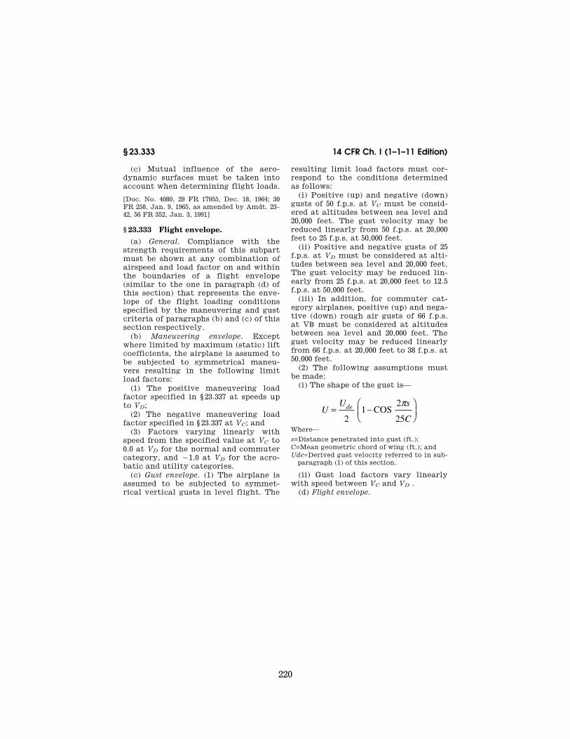
220
14 CFR Ch. I (1–1–11 Edition) § 23.333
(c) Mutual influence of the aero-dynamic surfaces must be taken into account when determining flight loads.
[Doc. No. 4080, 29 FR 17955, Dec. 18, 1964; 30 FR 258, Jan. 9, 1965, as amended by Amdt. 23– 42, 56 FR 352, Jan. 3, 1991]
§ 23.333 Flight envelope.
(a) General. Compliance with the strength requirements of this subpart must be shown at any combination of airspeed and load factor on and within the boundaries of a flight envelope (similar to the one in paragraph (d) of this section) that represents the enve-lope of the flight loading conditions specified by the maneuvering and gust criteria of paragraphs (b) and (c) of this section respectively.
(b) Maneuvering envelope. Except where limited by maximum (static) lift coefficients, the airplane is assumed to be subjected to symmetrical maneu-vers resulting in the following limit load factors:
(1) The positive maneuvering load factor specified in § 23.337 at speeds up to VD;
(2) The negative maneuvering load factor specified in § 23.337 at VC; and
(3) Factors varying linearly with speed from the specified value at VC to 0.0 at VD for the normal and commuter category, and ¥1.0 at VD for the acro-batic and utility categories.
(c) Gust envelope. (1) The airplane is assumed to be subjected to symmet-rical vertical gusts in level flight. The
resulting limit load factors must cor-respond to the conditions determined as follows:
(i) Positive (up) and negative (down) gusts of 50 f.p.s. at VC must be consid-ered at altitudes between sea level and 20,000 feet. The gust velocity may be reduced linearly from 50 f.p.s. at 20,000 feet to 25 f.p.s. at 50,000 feet.
(ii) Positive and negative gusts of 25 f.p.s. at VD must be considered at alti-tudes between sea level and 20,000 feet. The gust velocity may be reduced lin-early from 25 f.p.s. at 20,000 feet to 12.5 f.p.s. at 50,000 feet.
(iii) In addition, for commuter cat-egory airplanes, positive (up) and nega-tive (down) rough air gusts of 66 f.p.s. at VB must be considered at altitudes between sea level and 20,000 feet. The gust velocity may be reduced linearly from 66 f.p.s. at 20,000 feet to 38 f.p.s. at 50,000 feet.
(2) The following assumptions must be made:
(i) The shape of the gust is—
UU s
C
de= −⎛⎝⎜
⎞⎠⎟2
12
25COS
π
Where—
s=Distance penetrated into gust (ft.); C=Mean geometric chord of wing (ft.); and Ude=Derived gust velocity referred to in sub-
paragraph (1) of this section.
(ii) Gust load factors vary linearly with speed between VC and VD .
(d) Flight envelope.
VerDate Mar<15>2010 14:10 Mar 01, 2011 Jkt 223043 PO 00000 Frm 00230 Fmt 8010 Sfmt 8010 Y:\SGML\223043.XXX 223043 EC
28S
E91
.000
</M
AT
H>
ww
oods
2 on
DS
K1D
XX
6B1P
RO
D w
ith C
FR

221
Federal Aviation Administration, DOT § 23.335
[Doc. No. 4080, 29 FR 17955, Dec. 18, 1964, as amended by Amdt. 23–7, 34 FR 13087, Aug. 13, 1969; Amdt. 23–34, 52 FR 1829, Jan. 15, 1987]
§ 23.335 Design airspeeds. Except as provided in paragraph
(a)(4) of this section, the selected de-sign airspeeds are equivalent airspeeds (EAS).
(a) Design cruising speed, VC. For VC the following apply:
(1) Where W/S′=wing loading at the design maximum takeoff weight, Vc (in knots) may not be less than—
(i) 33 √(W/S) (for normal, utility, and commuter category airplanes);
(ii) 36 √(W/S) (for acrobatic category airplanes).
(2) For values of W/S more than 20, the multiplying factors may be de-creased linearly with W/S to a value of 28.6 where W/S=100.
(3) VC need not be more than 0.9 VH at sea level.
(4) At altitudes where an MD is estab-lished, a cruising speed MC limited by compressibility may be selected.
(b) Design dive speed VD. For VD, the following apply:
(1) VD/MD may not be less than 1.25 VC/MC; and
(2) With VC min, the required min-imum design cruising speed, VD (in knots) may not be less than—
(i) 1.40 Vc min (for normal and com-muter category airplanes);
(ii) 1.50 VC min (for utility category airplanes); and
(iii) 1.55 VC min (for acrobatic cat-egory airplanes).
(3) For values of W/S more than 20, the multiplying factors in paragraph (b)(2) of this section may be decreased linearly with W/S to a value of 1.35 where W/S=100.
(4) Compliance with paragraphs (b)(1) and (2) of this section need not be shown if VD/MD is selected so that the minimum speed margin between VC/MC and VD/MD is the greater of the fol-lowing:
(i) The speed increase resulting when, from the initial condition of stabilized flight at VC/MC, the airplane is assumed to be upset, flown for 20 seconds along a flight path 7.5° below the initial path, and then pulled up with a load factor of 1.5 (0.5 g. acceleration increment). At least 75 percent maximum continuous power for reciprocating engines, and maximum cruising power for turbines, or, if less, the power required for VC/MC for both kinds of engines, must be as-sumed until the pullup is initiated, at which point power reduction and pilot- controlled drag devices may be used; and either—
VerDate Mar<15>2010 14:10 Mar 01, 2011 Jkt 223043 PO 00000 Frm 00231 Fmt 8010 Sfmt 8010 Y:\SGML\223043.XXX 223043 EC
28S
E91
.001
</G
PH
>
ww
oods
2 on
DS
K1D
XX
6B1P
RO
D w
ith C
FR

222
14 CFR Ch. I (1–1–11 Edition) § 23.337
(ii) Mach 0.05 for normal, utility, and acrobatic category airplanes (at alti-tudes where MD is established); or
(iii) Mach 0.07 for commuter category airplanes (at altitudes where MD is es-tablished) unless a rational analysis, including the effects of automatic sys-tems, is used to determine a lower mar-gin. If a rational analysis is used, the minimum speed margin must be enough to provide for atmospheric variations (such as horizontal gusts), and the penetration of jet streams or cold fronts), instrument errors, air-frame production variations, and must not be less than Mach 0.05.
(c) Design maneuvering speed VA. For VA, the following applies:
(1) VA may not be less than VS√n where—
(i) VS is a computed stalling speed with flaps retracted at the design weight, normally based on the max-imum airplane normal force coeffi-cients, CNA; and
(ii) n is the limit maneuvering load factor used in design
(2) The value of VA need not exceed the value of VC used in design.
(d) Design speed for maximum gust in-tensity, VB. For VB, the following apply:
(1) VB may not be less than the speed determined by the intersection of the line representing the maximum posi-tive lift, CNMAX, and the line rep-resenting the rough air gust velocity on the gust V-n diagram, or VS1√ ng, whichever is less, where:
(i) ng the positive airplane gust load factor due to gust, at speed VC (in ac-cordance with § 23.341), and at the par-ticular weight under consideration; and
(ii) VS1 is the stalling speed with the flaps retracted at the particular weight under consideration.
(2) VB need not be greater than VC.
[Doc. No. 4080, 29 FR 17955, Dec. 18, 1964, as amended by Amdt. 23–7, 34 FR 13088, Aug. 13, 1969; Amdt. 23–16, 40 FR 2577, Jan. 14, 1975; Amdt. 23–34, 52 FR 1829, Jan. 15, 1987; Amdt. 23–24, 52 FR 34745, Sept. 14, 1987; Amdt. 23–48, 61 FR 5143, Feb. 9, 1996]
§ 23.337 Limit maneuvering load fac-tors.
(a) The positive limit maneuvering load factor n may not be less than—
(1) 2.1+(24,000÷(W+10,000)) for normal and commuter category airplanes,
where W=design maximum takeoff weight, except that n need not be more than 3.8;
(2) 4.4 for utility category airplanes; or
(3) 6.0 for acrobatic category air-planes.
(b) The negative limit maneuvering load factor may not be less than—
(1) 0.4 times the positive load factor for the normal utility and commuter categories; or
(2) 0.5 times the positive load factor for the acrobatic category.
(c) Maneuvering load factors lower than those specified in this section may be used if the airplane has design features that make it impossible to ex-ceed these values in flight.
[Doc. No. 4080, 29 FR 17955, Dec. 18, 1964, as amended by Amdt. 23–7, 34 FR 13088, Aug. 13, 1969; Amdt. 23–34, 52 FR 1829, Jan. 15, 1987; Amdt. 23–48, 61 FR 5144, Feb. 9, 1996]
§ 23.341 Gust loads factors. (a) Each airplane must be designed to
withstand loads on each lifting surface resulting from gusts specified in § 23.333(c).
(b) The gust load for a canard or tan-dem wing configuration must be com-puted using a rational analysis, or may be computed in accordance with para-graph (c) of this section, provided that the resulting net loads are shown to be conservative with respect to the gust criteria of § 23.333(c).
(c) In the absence of a more rational analysis, the gust load factors must be computed as follows—
nK U V a
W S
g de= +1498 ( / )
Where—
Kg=0.88μg/5.3+μg=gust alleviation factor; μg=2(W/S)/r Cag=airplane mass ratio; Ude=Derived gust velocities referred to in
§ 23.333(c) (f.p.s.); r=Density of air (slugs/cu.ft.); W/S=Wing loading (p.s.f.) due to the applica-
ble weight of the airplane in the particular load case.
W/S=Wing loading (p.s.f.); C=Mean geometric chord (ft.); g=Acceleration due to gravity (ft./sec.2) V=Airplane equivalent speed (knots); and a=Slope of the airplane normal force coeffi-
cient curve CNA per radian if the gust loads are applied to the wings and horizontal tail
VerDate Mar<15>2010 14:10 Mar 01, 2011 Jkt 223043 PO 00000 Frm 00232 Fmt 8010 Sfmt 8010 Y:\SGML\223043.XXX 223043 ER
09F
E96
.010
</M
AT
H>
ww
oods
2 on
DS
K1D
XX
6B1P
RO
D w
ith C
FR

223
Federal Aviation Administration, DOT § 23.347
surfaces simultaneously by a rational method. The wing lift curve slope CL per radian may be used when the gust load is applied to the wings only and the hori-zontal tail gust loads are treated as a sepa-rate condition.
[Amdt. 23–7, 34 FR 13088, Aug. 13, 1969, as amended by Amdt. 23–42, 56 FR 352, Jan. 3, 1991; Amdt. 23–48, 61 FR 5144, Feb. 9, 1996]
§ 23.343 Design fuel loads. (a) The disposable load combinations
must include each fuel load in the range from zero fuel to the selected maximum fuel load.
(b) If fuel is carried in the wings, the maximum allowable weight of the air-plane without any fuel in the wing tank(s) must be established as ‘‘max-imum zero wing fuel weight,’’ if it is less than the maximum weight.
(c) For commuter category airplanes, a structural reserve fuel condition, not exceeding fuel necessary for 45 minutes of operation at maximum continuous power, may be selected. If a structural reserve fuel condition is selected, it must be used as the minimum fuel weight condition for showing compli-ance with the flight load requirements prescribed in this part and—
(1) The structure must be designed to withstand a condition of zero fuel in the wing at limit loads corresponding to:
(i) Ninety percent of the maneu-vering load factors defined in § 23.337, and
(ii) Gust velocities equal to 85 per-cent of the values prescribed in § 23.333(c).
(2) The fatigue evaluation of the structure must account for any in-crease in operating stresses resulting from the design condition of paragraph (c)(1) of this section.
(3) The flutter, deformation, and vi-bration requirements must also be met with zero fuel in the wings.
[Doc. No. 27805, 61 FR 5144, Feb. 9, 1996]
§ 23.345 High lift devices. (a) If flaps or similar high lift devices
are to be used for takeoff, approach or landing, the airplane, with the flaps fully extended at VF, is assumed to be subjected to symmetrical maneuvers and gusts within the range determined by—
(1) Maneuvering, to a positive limit load factor of 2.0; and
(2) Positive and negative gust of 25 feet per second acting normal to the flight path in level flight.
(b) VF must be assumed to be not less than 1.4 VS or 1.8 VSF, whichever is greater, where—
(1) VS is the computed stalling speed with flaps retracted at the design weight; and
(2) VSF is the computed stalling speed with flaps fully extended at the design weight.
(3) If an automatic flap load limiting device is used, the airplane may be de-signed for the critical combinations of airspeed and flap position allowed by that device.
(c) In determining external loads on the airplane as a whole, thrust, slip-stream, and pitching acceleration may be assumed to be zero.
(d) The flaps, their operating mecha-nism, and their supporting structures, must be designed to withstand the con-ditions prescribed in paragraph (a) of this section. In addition, with the flaps fully extended at VF, the following con-ditions, taken separately, must be ac-counted for:
(1) A head-on gust having a velocity of 25 feet per second (EAS), combined with propeller slipstream cor-responding to 75 percent of maximum continuous power; and
(2) The effects of propeller slipstream corresponding to maximum takeoff power.
[Doc. No. 27805, 61 FR 5144, Feb. 9, 1996]
§ 23.347 Unsymmetrical flight condi-tions.
(a) The airplane is assumed to be sub-jected to the unsymmetrical flight con-ditions of §§ 23.349 and 23.351. Unbal-anced aerodynamic moments about the center of gravity must be reacted in a rational or conservative manner, con-sidering the principal masses fur-nishing the reacting inertia forces.
(b) Acrobatic category airplanes cer-tified for flick maneuvers (snap roll) must be designed for additional asym-metric loads acting on the wing and the horizontal tail.
[Doc. No. 4080, 29 FR 17955, Dec. 18, 1964, as amended by Amdt. 23–48, 61 FR 5144, Feb. 9, 1996]
VerDate Mar<15>2010 14:10 Mar 01, 2011 Jkt 223043 PO 00000 Frm 00233 Fmt 8010 Sfmt 8010 Y:\SGML\223043.XXX 223043ww
oods
2 on
DS
K1D
XX
6B1P
RO
D w
ith C
FR

224
14 CFR Ch. I (1–1–11 Edition) § 23.349
§ 23.349 Rolling conditions.
The wing and wing bracing must be designed for the following loading con-ditions:
(a) Unsymmetrical wing loads appro-priate to the category. Unless the fol-lowing values result in unrealistic loads, the rolling accelerations may be obtained by modifying the symmet-rical flight conditions in § 23.333(d) as follows:
(1) For the acrobatic category, in conditions A and F, assume that 100 percent of the semispan wing airload acts on one side of the plane of sym-metry and 60 percent of this load acts on the other side.
(2) For normal, utility, and com-muter categories, in Condition A, as-sume that 100 percent of the semispan wing airload acts on one side of the air-plane and 75 percent of this load acts on the other side.
(b) The loads resulting from the aile-ron deflections and speeds specified in § 23.455, in combination with an air-plane load factor of at least two thirds of the positive maneuvering load factor used for design. Unless the following values result in unrealistic loads, the effect of aileron displacement on wing torsion may be accounted for by adding the following increment to the basic airfoil moment coefficient over the ai-leron portion of the span in the critical condition determined in § 23.333(d):
Dcm=¥0.01d
where—
Dcm is the moment coefficient increment; and d is the down aileron deflection in degrees in
the critical condition.
[Doc. No. 4080, 29 FR 17955, Dec. 18, 1964, as amended by Amdt. 23–7, 34 FR 13088, Aug. 13, 1969; Amdt. 23–34, 52 FR 1829, Jan. 15, 1987; Amdt. 23–48, 61 FR 5144, Feb. 9, 1996]
§ 23.351 Yawing conditions.
The airplane must be designed for yawing loads on the vertical surfaces resulting from the loads specified in §§ 23.441 through 23.445.
[Doc. No. 4080, 29 FR 17955, Dec. 18, 1964; 30 FR 258, Jan. 9, 1965, as amended by Amdt. 23– 42, 56 FR 352, Jan. 3, 1991]
§ 23.361 Engine torque. (a) Each engine mount and its sup-
porting structure must be designed for the effects of—
(1) A limit engine torque cor-responding to takeoff power and pro-peller speed acting simultaneously with 75 percent of the limit loads from flight condition A of § 23.333(d);
(2) A limit engine torque cor-responding to maximum continuous power and propeller speed acting si-multaneously with the limit loads from flight condition A of § 23.333(d); and
(3) For turbopropeller installations, in addition to the conditions specified in paragraphs (a)(1) and (a)(2) of this section, a limit engine torque cor-responding to takeoff power and pro-peller speed, multiplied by a factor ac-counting for propeller control system malfunction, including quick feath-ering, acting simultaneously with lg level flight loads. In the absence of a rational analysis, a factor of 1.6 must be used.
(b) For turbine engine installations, the engine mounts and supporting structure must be designed to with-stand each of the following:
(1) A limit engine torque load im-posed by sudden engine stoppage due to malfunction or structural failure (such as compressor jamming).
(2) A limit engine torque load im-posed by the maximum acceleration of the engine.
(c) The limit engine torque to be con-sidered under paragraph (a) of this sec-tion must be obtained by multiplying the mean torque by a factor of—
(1) 1.25 for turbopropeller installa-tions;
(2) 1.33 for engines with five or more cylinders; and
(3) Two, three, or four, for engines with four, three, or two cylinders, re-spectively.
[Amdt. 23–26, 45 FR 60171, Sept. 11, 1980, as amended by Amdt. 23–45, 58 FR 42160, Aug. 6, 1993]
§ 23.363 Side load on engine mount. (a) Each engine mount and its sup-
porting structure must be designed for a limit load factor in a lateral direc-tion, for the side load on the engine mount, of not less than—
(1) 1.33, or
VerDate Mar<15>2010 14:10 Mar 01, 2011 Jkt 223043 PO 00000 Frm 00234 Fmt 8010 Sfmt 8010 Y:\SGML\223043.XXX 223043ww
oods
2 on
DS
K1D
XX
6B1P
RO
D w
ith C
FR

225
Federal Aviation Administration, DOT § 23.371
(2) One-third of the limit load factor for flight condition A.
(b) The side load prescribed in para-graph (a) of this section may be as-sumed to be independent of other flight conditions.
§ 23.365 Pressurized cabin loads. For each pressurized compartment,
the following apply: (a) The airplane structure must be
strong enough to withstand the flight loads combined with pressure differen-tial loads from zero up to the max-imum relief valve setting.
(b) The external pressure distribution in flight, and any stress concentra-tions, must be accounted for.
(c) If landings may be made with the cabin pressurized, landing loads must be combined with pressure differential loads from zero up to the maximum al-lowed during landing.
(d) The airplane structure must be strong enough to withstand the pres-sure differential loads corresponding to the maximum relief valve setting mul-tiplied by a factor of 1.33, omitting other loads.
(e) If a pressurized cabin has two or more compartments separated by bulk-heads or a floor, the primary structure must be designed for the effects of sud-den release of pressure in any compart-ment with external doors or windows. This condition must be investigated for the effects of failure of the largest opening in the compartment. The ef-fects of intercompartmental venting may be considered.
§ 23.367 Unsymmetrical loads due to engine failure.
(a) Turbopropeller airplanes must be designed for the unsymmetrical loads resulting from the failure of the crit-ical engine including the following con-ditions in combination with a single malfunction of the propeller drag lim-iting system, considering the probable pilot corrective action on the flight controls:
(1) At speeds between VMC and VD, the loads resulting from power failure because of fuel flow interruption are considered to be limit loads.
(2) At speeds between VMC and VC, the loads resulting from the disconnection of the engine compressor from the tur-
bine or from loss of the turbine blades are considered to be ultimate loads.
(3) The time history of the thrust decay and drag buildup occurring as a result of the prescribed engine failures must be substantiated by test or other data applicable to the particular en-gine-propeller combination.
(4) The timing and magnitude of the probable pilot corrective action must be conservatively estimated, consid-ering the characteristics of the par-ticular engine-propeller-airplane com-bination.
(b) Pilot corrective action may be as-sumed to be initiated at the time max-imum yawing velocity is reached, but not earlier than 2 seconds after the en-gine failure. The magnitude of the cor-rective action may be based on the limit pilot forces specified in § 23.397 except that lower forces may be as-sumed where it is shown by analysis or test that these forces can control the yaw and roll resulting from the pre-scribed engine failure conditions.
[Amdt. 23–7, 34 FR 13089, Aug. 13, 1969]
§ 23.369 Rear lift truss. (a) If a rear lift truss is used, it must
be designed to withstand conditions of reversed airflow at a design speed of—
V=8.7 √(W/S) + 8.7 (knots), where W/ S=wing loading at design maximum takeoff weight.
(b) Either aerodynamic data for the particular wing section used, or a value of CL equalling ¥0.8 with a chordwise distribution that is triangular between a peak at the trailing edge and zero at the leading edge, must be used.
[Doc. No. 4080, 29 FR 17955, Dec. 18, 1964, as amended by Amdt. 23–7, 34 FR 13089, Aug. 13, 1969; 34 FR 17509, Oct. 30, 1969; Amdt. 23–45, 58 FR 42160, Aug. 6, 1993; Amdt. 23–48, 61 FR 5145, Feb. 9, 1996]
§ 23.371 Gyroscopic and aerodynamic loads.
(a) Each engine mount and its sup-porting structure must be designed for the gyroscopic, inertial, and aero-dynamic loads that result, with the en-gine(s) and propeller(s), if applicable, at maximum continuous r.p.m., under either:
(1) The conditions prescribed in § 23.351 and § 23.423; or
VerDate Mar<15>2010 14:10 Mar 01, 2011 Jkt 223043 PO 00000 Frm 00235 Fmt 8010 Sfmt 8010 Y:\SGML\223043.XXX 223043ww
oods
2 on
DS
K1D
XX
6B1P
RO
D w
ith C
FR

226
14 CFR Ch. I (1–1–11 Edition) § 23.373
(2) All possible combinations of the following—
(i) A yaw velocity of 2.5 radians per second;
(ii) A pitch velocity of 1.0 radian per second;
(iii) A normal load factor of 2.5; and (iv) Maximum continuous thrust. (b) For airplanes approved for aero-
batic maneuvers, each engine mount and its supporting structure must meet the requirements of paragraph (a) of this section and be designed to with-stand the load factors expected during combined maximum yaw and pitch ve-locities.
(c) For airplanes certificated in the commuter category, each engine mount and its supporting structure must meet the requirements of para-graph (a) of this section and the gust conditions specified in § 23.341 of this part.
[Doc. No. 27805, 61 FR 5145, Feb. 9, 1996]
§ 23.373 Speed control devices.
If speed control devices (such as spoilers and drag flaps) are incor-porated for use in enroute conditions—
(a) The airplane must be designed for the symmetrical maneuvers and gusts prescribed in §§ 23.333, 23.337, and 23.341, and the yawing maneuvers and lateral gusts in §§ 23.441 and 23.443, with the de-vice extended at speeds up to the placard device extended speed; and
(b) If the device has automatic oper-ating or load limiting features, the air-plane must be designed for the maneu-ver and gust conditions prescribed in paragraph (a) of this section at the speeds and corresponding device posi-tions that the mechanism allows.
[Amdt. 23–7, 34 FR 13089, Aug. 13, 1969]
CONTROL SURFACE AND SYSTEM LOADS
§ 23.391 Control surface loads.
The control surface loads specified in §§ 23.397 through 23.459 are assumed to occur in the conditions described in §§ 23.331 through 23.351.
[Doc. No. 4080, 29 FR 17955, Dec. 18, 1964, as amended by Amdt. 23–48, 61 FR 5145, Feb. 9, 1996]
§ 23.393 Loads parallel to hinge line. (a) Control surfaces and supporting
hinge brackets must be designed to withstand inertial loads acting parallel to the hinge line.
(b) In the absence of more rational data, the inertial loads may be as-sumed to be equal to KW, where—
(1) K=24 for vertical surfaces; (2) K=12 for horizontal surfaces; and (3) W=weight of the movable surfaces.
[Doc. No. 27805, 61 FR 5145, Feb. 9, 1996]
§ 23.395 Control system loads. (a) Each flight control system and its
supporting structure must be designed for loads corresponding to at least 125 percent of the computed hinge mo-ments of the movable control surface in the conditions prescribed in §§ 23.391 through 23.459. In addition, the fol-lowing apply:
(1) The system limit loads need not exceed the higher of the loads that can be produced by the pilot and automatic devices operating the controls. How-ever, autopilot forces need not be added to pilot forces. The system must be de-signed for the maximum effort of the pilot or autopilot, whichever is higher. In addition, if the pilot and the auto-pilot act in opposition, the part of the system between them may be designed for the maximum effort of the one that imposes the lesser load. Pilot forces used for design need not exceed the maximum forces prescribed in § 23.397(b).
(2) The design must, in any case, pro-vide a rugged system for service use, considering jamming, ground gusts, taxiing downwind, control inertia, and friction. Compliance with this subpara-graph may be shown by designing for loads resulting from application of the minimum forces prescribed in § 23.397(b).
(b) A 125 percent factor on computed hinge moments must be used to design elevator, aileron, and rudder systems. However, a factor as low as 1.0 may be used if hinge moments are based on ac-curate flight test data, the exact reduc-tion depending upon the accuracy and reliability of the data.
(c) Pilot forces used for design are as-sumed to act at the appropriate control grips or pads as they would in flight,
VerDate Mar<15>2010 14:10 Mar 01, 2011 Jkt 223043 PO 00000 Frm 00236 Fmt 8010 Sfmt 8010 Y:\SGML\223043.XXX 223043ww
oods
2 on
DS
K1D
XX
6B1P
RO
D w
ith C
FR

227
Federal Aviation Administration, DOT § 23.415
and to react at the attachments of the control system to the control surface horns.
[Doc. No. 4080, 29 FR 17955, Dec. 18, 1964, as amended by Amdt. 23–7, 34 FR 13089, Aug. 13, 1969]
§ 23.397 Limit control forces and torques.
(a) In the control surface flight load-ing condition, the airloads on movable surfaces and the corresponding deflec-tions need not exceed those that would result in flight from the application of any pilot force within the ranges speci-fied in paragraph (b) of this section. In applying this criterion, the effects of control system boost and servo-mecha-nisms, and the effects of tabs must be considered. The automatic pilot effort must be used for design if it alone can produce higher control surface loads than the human pilot.
(b) The limit pilot forces and torques are as follows:
Control
Maximum forces or torques for design weight, weight equal to
or less than 5,000 pounds 1
Minimum forces or torques 2
Aileron: Stick ................................ 67 lbs ................ 40 lbs. Wheel 3 ............................ 50 D in.-lbs 4 ..... 40 D in.-
lbs.4 Elevator:
Stick ................................ 167 lbs .............. 100 lbs. Wheel (symmetrical) ....... 200 lbs .............. 100 lbs. Wheel (unsymmetrical) 5 ........................... 100 lbs.
Rudder ................................ 200 lbs .............. 150 lbs.
1 For design weight (W) more than 5,000 pounds, the speci-fied maximum values must be increased linearly with weight to 1.18 times the specified values at a design weight of 12,500 pounds and for commuter category airplanes, the specified values must be increased linearly with weight to 1.35 times the specified values at a design weight of 19,000 pounds.
2 If the design of any individual set of control systems or surfaces makes these specified minimum forces or torques in-applicable, values corresponding to the present hinge mo-ments obtained under § 23.415, but not less than 0.6 of the specified minimum forces or torques, may be used.
3 The critical parts of the aileron control system must also be designed for a single tangential force with a limit value of 1.25 times the couple force determined from the above cri-teria.
4 D=wheel diameter (inches). 5 The unsymmetrical force must be applied at one of the
normal handgrip points on the control wheel.
[Doc. No. 4080, 29 FR 17955, Dec. 18, 1964, as amended by Amdt. 23–7, 34 FR 13089, Aug. 13, 1969; Amdt. 23–17, 41 FR 55464, Dec. 20, 1976; Amdt. 23–34, 52 FR 1829, Jan. 15, 1987; Amdt. 23–45, 58 FR 42160, Aug. 6, 1993]
§ 23.399 Dual control system.
(a) Each dual control system must be designed to withstand the force of the pilots operating in opposition, using in-dividual pilot forces not less than the greater of—
(1) 0.75 times those obtained under § 23.395; or
(2) The minimum forces specified in § 23.397(b).
(b) Each dual control system must be designed to withstand the force of the pilots applied together, in the same di-rection, using individual pilot forces not less than 0.75 times those obtained under § 23.395.
[Doc. No. 27805, 61 FR 5145, Feb. 9, 1996]
§ 23.405 Secondary control system.
Secondary controls, such as wheel brakes, spoilers, and tab controls, must be designed for the maximum forces that a pilot is likely to apply to those controls.
§ 23.407 Trim tab effects.
The effects of trim tabs on the con-trol surface design conditions must be accounted for only where the surface loads are limited by maximum pilot ef-fort. In these cases, the tabs are con-sidered to be deflected in the direction that would assist the pilot. These de-flections must correspond to the max-imum degree of ‘‘out of trim’’ expected at the speed for the condition under consideration.
§ 23.409 Tabs.
Control surface tabs must be de-signed for the most severe combination of airspeed and tab deflection likely to be obtained within the flight envelope for any usable loading condition.
§ 23.415 Ground gust conditions.
(a) The control system must be inves-tigated as follows for control surface loads due to ground gusts and taxiing downwind:
(1) If an investigation of the control system for ground gust loads is not re-quired by paragraph (a)(2) of this sec-tion, but the applicant elects to design a part of the control system of these loads, these loads need only be carried from control surface horns through the
VerDate Mar<15>2010 14:10 Mar 01, 2011 Jkt 223043 PO 00000 Frm 00237 Fmt 8010 Sfmt 8010 Y:\SGML\223043.XXX 223043ww
oods
2 on
DS
K1D
XX
6B1P
RO
D w
ith C
FR
228
14 CFR Ch. I (1–1–11 Edition) § 23.421
nearest stops or gust locks and their supporting structures.
(2) If pilot forces less than the mini-mums specified in § 23.397(b) are used for design, the effects of surface loads due to ground gusts and taxiing down-wind must be investigated for the en-tire control system according to the formula:
H=K c S q
where—
H=limit hinge moment (ft.-lbs.); c=mean chord of the control surface aft of
the hinge line (ft.); S=area of control surface aft of the hinge
line (sq. ft.); q=dynamic pressure (p.s.f.) based on a design
speed not less than 14.6 √(W/S) + 14.6 (f.p.s.) where W/S=wing loading at design max-imum weight, except that the design speed need not exceed 88 (f.p.s.);
K=limit hinge moment factor for ground gusts derived in paragraph (b) of this sec-tion. (For ailerons and elevators, a positive value of K indicates a moment tending to depress the surface and a negative value of K indicates a moment tending to raise the surface).
(b) The limit hinge moment factor K for ground gusts must be derived as fol-lows:
Surface K Position of controls
(a) Aileron ......... 0.75 Control column locked lashed in mid-position.
(b) Aileron ......... ±0.50 Ailerons at full throw; + moment on one aileron, ¥ moment on the other.
(c) Elevator ....... ±0.75 (c) Elevator full up (¥). (d) Elevator ....... ............ (d) Elevator full down (+). (e) Rudder ......... ±0.75 (e) Rudder in neutral. (f) Rudder .......... ............ (f) Rudder at full throw.
(c) At all weights between the empty weight and the maximum weight de-clared for tie-down stated in the appro-priate manual, any declared tie-down points and surrounding structure, con-trol system, surfaces and associated gust locks, must be designed to with-stand the limit load conditions that exist when the airplane is tied down and that result from wind speeds of up to 65 knots horizontally from any di-rection.
[Doc. No. 4080, 29 FR 17955, Dec. 18, 1964, as amended by Amdt. 23–7, 34 FR 13089, Aug. 13, 1969; Amdt. 23–45, 58 FR 42160, Aug. 6, 1993; Amdt. 23–48, 61 FR 5145, Feb. 9, 1996]
HORIZONTAL STABILIZING AND BALANCING SURFACES
§ 23.421 Balancing loads.
(a) A horizontal surface balancing load is a load necessary to maintain equilibrium in any specified flight con-dition with no pitching acceleration.
(b) Horizontal balancing surfaces must be designed for the balancing loads occurring at any point on the limit maneuvering envelope and in the flap conditions specified in § 23.345.
[Doc. No. 4080, 29 FR 17955, Dec. 18, 1964, as amended by Amdt. 23–7, 34 FR 13089, Aug. 13, 1969; Amdt. 23–42, 56 FR 352, Jan. 3, 1991]
§ 23.423 Maneuvering loads.
Each horizontal surface and its sup-porting structure, and the main wing of a canard or tandem wing configura-tion, if that surface has pitch control, must be designed for the maneuvering loads imposed by the following condi-tions:
(a) A sudden movement of the pitch-ing control, at the speed VA, to the maximum aft movement, and the max-imum forward movement, as limited by the control stops, or pilot effort, whichever is critical.
(b) A sudden aft movement of the pitching control at speeds above VA, followed by a forward movement of the pitching control resulting in the fol-lowing combinations of normal and an-gular acceleration:
Condition Normal
accelera-tion (n)
Angular acceleration (radian/sec2)
Nose-up pitching ........ 1.0 +39nm÷V×(nm¥1.5) Nose-down pitching .... nm ¥39nm÷V×(nm¥1.5)
where— (1) nm=positive limit maneuvering
load factor used in the design of the airplane; and
(2) V=initial speed in knots. The conditions in this paragraph in-
volve loads corresponding to the loads that may occur in a ‘‘checked maneu-ver’’ (a maneuver in which the pitching control is suddenly displaced in one di-rection and then suddenly moved in the opposite direction). The deflections and timing of the ‘‘checked maneuver’’ must avoid exceeding the limit maneuvering
VerDate Mar<15>2010 14:10 Mar 01, 2011 Jkt 223043 PO 00000 Frm 00238 Fmt 8010 Sfmt 8010 Y:\SGML\223043.XXX 223043ww
oods
2 on
DS
K1D
XX
6B1P
RO
D w
ith C
FR

229
Federal Aviation Administration, DOT § 23.441
load factor. The total horizontal sur-face load for both nose-up and nose- down pitching conditions is the sum of the balancing loads at V and the speci-fied value of the normal load factor n, plus the maneuvering load increment due to the specified value of the angu-lar acceleration.
[Amdt. 23–42, 56 FR 353, Jan. 3, 1991; 56 FR 5455, Feb. 11, 1991]
§ 23.425 Gust loads. (a) Each horizontal surface, other
than a main wing, must be designed for loads resulting from—
(1) Gust velocities specified in § 23.333(c) with flaps retracted; and
(2) Positive and negative gusts of 25 f.p.s. nominal intensity at VF cor-responding to the flight conditions specified in § 23.345(a)(2).
(b) [Reserved] (c) When determining the total load
on the horizontal surfaces for the con-ditions specified in paragraph (a) of this section, the initial balancing loads for steady unaccelerated flight at the pertinent design speeds VF, VC, and VD must first be determined. The incre-mental load resulting from the gusts must be added to the initial balancing load to obtain the total load.
(d) In the absence of a more rational analysis, the incremental load due to the gust must be computed as follows only on airplane configurations with aft-mounted, horizontal surfaces, un-less its use elsewhere is shown to be conservative:
Δ LK U Va S
498ht
g de ht ht= −⎛⎝⎜
⎞⎠⎟
1d
d
ε
αwhere— DLht=Incremental horizontal tailload (lbs.); Kg=Gust alleviation factor defined in § 23.341; Ude=Derived gust velocity (f.p.s.); V=Airplane equivalent speed (knots); aht=Slope of aft horizontal lift curve (per ra-
dian) Sht=Area of aft horizontal lift surface (ft2);
and
1−⎛⎝⎜
⎞⎠⎟
=d
d
ε
αDownwash factor
[Doc. No. 4080, 29 FR 17955, Dec. 18, 1964, as amended by Amdt. 23–7, 34 FR 13089 Aug. 13, 1969; Amdt. 23–42, 56 FR 353, Jan. 3, 1991]
§ 23.427 Unsymmetrical loads. (a) Horizontal surfaces other than
main wing and their supporting struc-ture must be designed for unsymmet-rical loads arising from yawing and slipstream effects, in combination with the loads prescribed for the flight con-ditions set forth in §§ 23.421 through 23.425.
(b) In the absence of more rational data for airplanes that are conven-tional in regard to location of engines, wings, horizontal surfaces other than main wing, and fuselage shape:
(1) 100 percent of the maximum load-ing from the symmetrical flight condi-tions may be assumed on the surface on one side of the plane of symmetry; and
(2) The following percentage of that loading must be applied to the opposite side:
Percent=100¥10 (n¥1), where n is the spec-ified positive maneuvering load factor, but this value may not be more than 80 percent.
(c) For airplanes that are not conven-tional (such as airplanes with hori-zontal surfaces other than main wing having appreciable dihedral or sup-ported by the vertical tail surfaces) the surfaces and supporting structures must be designed for combined vertical and horizontal surface loads resulting from each prescribed flight condition taken separately.
[Amdt. 23–14, 38 FR 31820, Nov. 19, 1973, as amended by Amdt. 23–42, 56 FR 353, Jan. 3, 1991]
VERTICAL SURFACES
§ 23.441 Maneuvering loads. (a) At speeds up to VA, the vertical
surfaces must be designed to withstand the following conditions. In computing the loads, the yawing velocity may be assumed to be zero:
(1) With the airplane in unacceler-ated flight at zero yaw, it is assumed that the rudder control is suddenly dis-placed to the maximum deflection, as limited by the control stops or by limit pilot forces.
(2) With the rudder deflected as speci-fied in paragraph (a)(1) of this section, it is assumed that the airplane yaws to the overswing sideslip angle. In lieu of a rational analysis, an overswing angle
VerDate Mar<15>2010 14:10 Mar 01, 2011 Jkt 223043 PO 00000 Frm 00239 Fmt 8010 Sfmt 8010 Y:\SGML\223043.XXX 223043 EC
28S
E91
.002
</M
AT
H>
EC
28S
E91
.003
</M
AT
H>
ww
oods
2 on
DS
K1D
XX
6B1P
RO
D w
ith C
FR
230
14 CFR Ch. I (1–1–11 Edition) § 23.441
equal to 1.5 times the static sideslip angle of paragraph (a)(3) of this section may be assumed.
(3) A yaw angle of 15 degrees with the rudder control maintained in the neu-tral position (except as limited by pilot strength).
(b) For commuter category airplanes, the loads imposed by the following ad-ditional maneuver must be substan-tiated at speeds from VA to VD/MD. When computing the tail loads—
(1) The airplane must be yawed to the largest attainable steady state sideslip angle, with the rudder at maximum de-flection caused by any one of the fol-lowing:
(i) Control surface stops; (ii) Maximum available booster ef-
fort; (iii) Maximum pilot rudder force as
shown below:
VerDate Mar<15>2010 14:10 Mar 01, 2011 Jkt 223043 PO 00000 Frm 00240 Fmt 8010 Sfmt 8010 Y:\SGML\223043.XXX 223043ww
oods
2 on
DS
K1D
XX
6B1P
RO
D w
ith C
FR
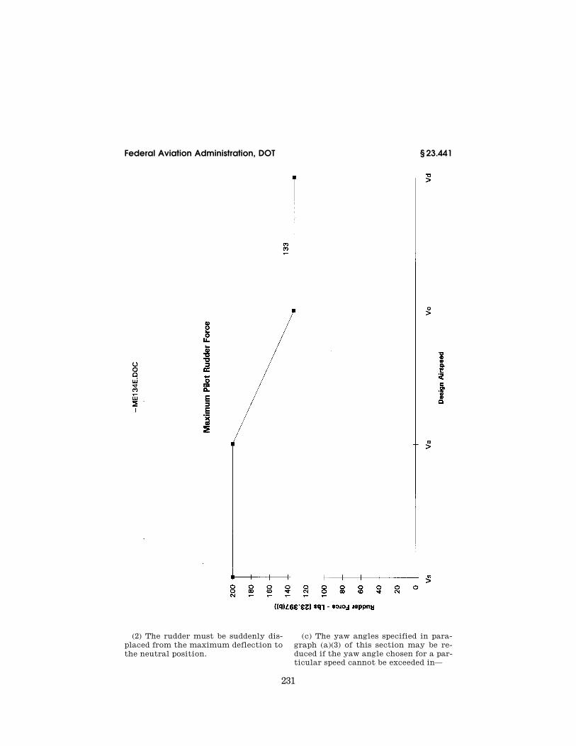
231
Federal Aviation Administration, DOT § 23.441
(2) The rudder must be suddenly dis-placed from the maximum deflection to the neutral position.
(c) The yaw angles specified in para-graph (a)(3) of this section may be re-duced if the yaw angle chosen for a par-ticular speed cannot be exceeded in—
VerDate Mar<15>2010 14:10 Mar 01, 2011 Jkt 223043 PO 00000 Frm 00241 Fmt 8010 Sfmt 8010 Y:\SGML\223043.XXX 223043 ER
09F
E96
.006
</G
PH
>
ww
oods
2 on
DS
K1D
XX
6B1P
RO
D w
ith C
FR
232
14 CFR Ch. I (1–1–11 Edition) § 23.443
(1) Steady slip conditions; (2) Uncoordinated rolls from steep
banks; or (3) Sudden failure of the critical en-
gine with delayed corrective action.
[Doc. No. 4080, 29 FR 17955, Dec. 18, 1964, as amended by Amdt. 23–7, 34 FR 13090, Aug. 13, 1969; Amdt. 23–14, 38 FR 31821, Nov. 19, 1973; Amdt. 23–28, 47 FR 13315, Mar. 29, 1982; Amdt. 23–42, 56 FR 353, Jan. 3, 1991; Amdt. 23–48, 61 FR 5145, Feb. 9, 1996]
§ 23.443 Gust loads.
(a) Vertical surfaces must be de-signed to withstand, in unaccelerated flight at speed VC, lateral gusts of the values prescribed for VC in § 23.333(c).
(b) In addition, for commuter cat-egory airplanes, the airplane is as-sumed to encounter derived gusts nor-mal to the plane of symmetry while in unaccelerated flight at VB, VC, VD, and VF. The derived gusts and airplane speeds corresponding to these condi-tions, as determined by §§ 23.341 and 23.345, must be investigated. The shape of the gust must be as specified in § 23.333(c)(2)(i).
(c) In the absence of a more rational analysis, the gust load must be com-puted as follows:
LK U V a S
vtgt de vt vt=
498Where—
Lvt=Vertical surface loads (lbs.);
kgtgt
gt
=+
=0 88
5 3
.
.
μμ
gust alleviation factor;
μρ
gt
t vt vt vt
W
c g a S
K
llateral= =
2 2
massratio;
Ude=Derived gust velocity (f.p.s.); r=Air density (slugs/cu.ft.); W=the applicable weight of the airplane in
the particular load case (lbs.); Svt=Area of vertical surface (ft.2); c̆≤t=Mean geometric chord of vertical surface
(ft.); avt=Lift curve slope of vertical surface (per
radian); K=Radius of gyration in yaw (ft.); lvt=Distance from airplane c.g. to lift center
of vertical surface (ft.); g=Acceleration due to gravity (ft./sec.2); and
V=Equivalent airspeed (knots).
[Amdt. 23–7, 34 FR 13090, Aug. 13, 1969, as amended by Amdt. 23–34, 52 FR 1830, Jan. 15, 1987; 52 FR 7262, Mar. 9, 1987; Amdt. 23–24, 52 FR 34745, Sept. 14, 1987; Amdt. 23–42, 56 FR 353, Jan. 3, 1991; Amdt. 23–48, 61 FR 5147, Feb. 9, 1996]
§ 23.445 Outboard fins or winglets.
(a) If outboard fins or winglets are in-cluded on the horizontal surfaces or wings, the horizontal surfaces or wings must be designed for their maximum load in combination with loads induced by the fins or winglets and moments or forces exerted on the horizontal sur-faces or wings by the fins or winglets.
(b) If outboard fins or winglets ex-tend above and below the horizontal surface, the critical vertical surface loading (the load per unit area as de-termined under §§ 23.441 and 23.443) must be applied to—
(1) The part of the vertical surfaces above the horizontal surface with 80 percent of that loading applied to the part below the horizontal surface; and
(2) The part of the vertical surfaces below the horizontal surface with 80 percent of that loading applied to the part above the horizontal surface.
(c) The end plate effects of outboard fins or winglets must be taken into ac-count in applying the yawing condi-tions of §§ 23.441 and 23.443 to the vertical surfaces in paragraph (b) of this section.
(d) When rational methods are used for computing loads, the maneuvering loads of § 23.441 on the vertical surfaces and the one-g horizontal surface load, including induced loads on the hori-zontal surface and moments or forces exerted on the horizontal surfaces by the vertical surfaces, must be applied simultaneously for the structural load-ing condition.
[Doc. No. 4080, 29 FR 17955, Dec. 18, 1964, as amended by Amdt. 23–14, 38 FR 31821, Nov. 19, 1973; Amdt. 23–42, 56 FR 353, Jan. 3, 1991]
AILERONS AND SPECIAL DEVICES
§ 23.455 Ailerons.
(a) The ailerons must be designed for the loads to which they are subjected—
(1) In the neutral position during symmetrical flight conditions; and
VerDate Mar<15>2010 14:10 Mar 01, 2011 Jkt 223043 PO 00000 Frm 00242 Fmt 8010 Sfmt 8010 Y:\SGML\223043.XXX 223043 ER
09F
E96
.000
</M
AT
H>
ER
09F
E96
.001
</M
AT
H>
ER
09F
E96
.002
</M
AT
H>
ww
oods
2 on
DS
K1D
XX
6B1P
RO
D w
ith C
FR

233
Federal Aviation Administration, DOT § 23.477
(2) By the following deflections (ex-cept as limited by pilot effort), during unsymmetrical flight conditions:
(i) Sudden maximum displacement of the aileron control at VA. Suitable al-lowance may be made for control sys-tem deflections.
(ii) Sufficient deflection at VC, where VC is more than VA, to produce a rate of roll not less than obtained in para-graph (a)(2)(i) of this section.
(iii) Sufficient deflection at VD to produce a rate of roll not less than one- third of that obtained in paragraph (a)(2)(i) of this section.
(b) [Reserved]
[Doc. No. 4080, 29 FR 17955, Dec. 18, 1964, as amended by Amdt. 23–7, 34 FR 13090, Aug. 13, 1969; Amdt. 23–42, 56 FR 353, Jan. 3, 1991]
§ 23.459 Special devices.
The loading for special devices using aerodynamic surfaces (such as slots and spoilers) must be determined from test data.
GROUND LOADS
§ 23.471 General.
The limit ground loads specified in this subpart are considered to be exter-nal loads and inertia forces that act upon an airplane structure. In each specified ground load condition, the ex-ternal reactions must be placed in equilibrium with the linear and angu-lar inertia forces in a rational or con-servative manner.
§ 23.473 Ground load conditions and assumptions.
(a) The ground load requirements of this subpart must be complied with at the design maximum weight except that §§ 23.479, 23.481, and 23.483 may be complied with at a design landing weight (the highest weight for landing conditions at the maximum descent ve-locity) allowed under paragraphs (b) and (c) of this section.
(b) The design landing weight may be as low as—
(1) 95 percent of the maximum weight if the minimum fuel capacity is enough for at least one-half hour of operation at maximum continuous power plus a capacity equal to a fuel weight which is the difference between the design
maximum weight and the design land-ing weight; or
(2) The design maximum weight less the weight of 25 percent of the total fuel capacity.
(c) The design landing weight of a multiengine airplane may be less than that allowed under paragraph (b) of this section if—
(1) The airplane meets the one-en-gine-inoperative climb requirements of § 23.67(b)(1) or (c); and
(2) Compliance is shown with the fuel jettisoning system requirements of § 23.1001.
(d) The selected limit vertical inertia load factor at the center of gravity of the airplane for the ground load condi-tions prescribed in this subpart may not be less than that which would be obtained when landing with a descent velocity (V), in feet per second, equal to 4.4 (W/S)1⁄4, except that this velocity need not be more than 10 feet per sec-ond and may not be less than seven feet per second.
(e) Wing lift not exceeding two-thirds of the weight of the airplane may be assumed to exist throughout the land-ing impact and to act through the cen-ter of gravity. The ground reaction load factor may be equal to the inertia load factor minus the ratio of the above assumed wing lift to the airplane weight.
(f) If energy absorption tests are made to determine the limit load fac-tor corresponding to the required limit descent velocities, these tests must be made under § 23.723(a).
(g) No inertia load factor used for de-sign purposes may be less than 2.67, nor may the limit ground reaction load fac-tor be less than 2.0 at design maximum weight, unless these lower values will not be exceeded in taxiing at speeds up to takeoff speed over terrain as rough as that expected in service.
[Doc. No. 4080, 29 FR 17955, Dec. 18, 1964, as amended by Amdt. 23–7, 34 FR 13090, Aug. 13, 1969; Amdt. 23–28, 47 FR 13315, Mar. 29, 1982; Amdt. 23–45, 58 FR 42160, Aug. 6, 1993; Amdt. 23–48, 61 FR 5147, Feb. 9, 1996]
§ 23.477 Landing gear arrangement.
Sections 23.479 through 23.483, or the conditions in appendix C, apply to air-planes with conventional arrangements
VerDate Mar<15>2010 14:10 Mar 01, 2011 Jkt 223043 PO 00000 Frm 00243 Fmt 8010 Sfmt 8010 Y:\SGML\223043.XXX 223043ww
oods
2 on
DS
K1D
XX
6B1P
RO
D w
ith C
FR
234
14 CFR Ch. I (1–1–11 Edition) § 23.479
of main and nose gear, or main and tail gear.
§ 23.479 Level landing conditions.
(a) For a level landing, the airplane is assumed to be in the following atti-tudes:
(1) For airplanes with tail wheels, a normal level flight attitude.
(2) For airplanes with nose wheels, attitudes in which—
(i) The nose and main wheels contact the ground simultaneously; and
(ii) The main wheels contact the ground and the nose wheel is just clear of the ground.
The attitude used in paragraph (a)(2)(i) of this section may be used in the anal-ysis required under paragraph (a)(2)(ii) of this section.
(b) When investigating landing condi-tions, the drag components simulating the forces required to accelerate the tires and wheels up to the landing speed (spin-up) must be properly com-bined with the corresponding instanta-neous vertical ground reactions, and the forward-acting horizontal loads re-sulting from rapid reduction of the spin-up drag loads (spring-back) must be combined with vertical ground reac-tions at the instant of the peak for-ward load, assuming wing lift and a tire-sliding coefficient of friction of 0.8. However, the drag loads may not be less than 25 percent of the maximum vertical ground reactions (neglecting wing lift).
(c) In the absence of specific tests or a more rational analysis for deter-mining the wheel spin-up and spring- back loads for landing conditions, the method set forth in appendix D of this part must be used. If appendix D of this part is used, the drag components used for design must not be less than those given by appendix C of this part.
(d) For airplanes with tip tanks or large overhung masses (such as turbo- propeller or jet engines) supported by the wing, the tip tanks and the struc-ture supporting the tanks or overhung masses must be designed for the effects of dynamic responses under the level landing conditions of either paragraph (a)(1) or (a)(2)(ii) of this section. In evaluating the effects of dynamic re-
sponse, an airplane lift equal to the weight of the airplane may be assumed.
[Doc. No. 4080, 29 FR 17955, Dec. 18, 1964, as amended by Amdt. 23–17, 41 FR 55464, Dec. 20, 1976; Amdt. 23–45, 58 FR 42160, Aug. 6, 1993]
§ 23.481 Tail down landing conditions.
(a) For a tail down landing, the air-plane is assumed to be in the following attitudes:
(1) For airplanes with tail wheels, an attitude in which the main and tail wheels contact the ground simulta-neously.
(2) For airplanes with nose wheels, a stalling attitude, or the maximum angle allowing ground clearance by each part of the airplane, whichever is less.
(b) For airplanes with either tail or nose wheels, ground reactions are as-sumed to be vertical, with the wheels up to speed before the maximum vertical load is attained.
§ 23.483 One-wheel landing conditions.
For the one-wheel landing condition, the airplane is assumed to be in the level attitude and to contact the ground on one side of the main landing gear. In this attitude, the ground reac-tions must be the same as those ob-tained on that side under § 23.479.
§ 23.485 Side load conditions.
(a) For the side load condition, the airplane is assumed to be in a level at-titude with only the main wheels con-tacting the ground and with the shock absorbers and tires in their static posi-tions.
(b) The limit vertical load factor must be 1.33, with the vertical ground reaction divided equally between the main wheels.
(c) The limit side inertia factor must be 0.83, with the side ground reaction divided between the main wheels so that—
(1) 0.5 (W) is acting inboard on one side; and
(2) 0.33 (W) is acting outboard on the other side.
(d) The side loads prescribed in para-graph (c) of this section are assumed to be applied at the ground contact point
VerDate Mar<15>2010 14:10 Mar 01, 2011 Jkt 223043 PO 00000 Frm 00244 Fmt 8010 Sfmt 8010 Y:\SGML\223043.XXX 223043ww
oods
2 on
DS
K1D
XX
6B1P
RO
D w
ith C
FR

235
Federal Aviation Administration, DOT § 23.499
and the drag loads may be assumed to be zero.
[Doc. No. 4080, 29 FR 17955, Dec. 18, 1964, as amended by Amdt. 23–45, 58 FR 42160, Aug. 6, 1993]
§ 23.493 Braked roll conditions.
Under braked roll conditions, with the shock absorbers and tires in their static positions, the following apply:
(a) The limit vertical load factor must be 1.33.
(b) The attitudes and ground con-tacts must be those described in § 23.479 for level landings.
(c) A drag reaction equal to the vertical reaction at the wheel multi-plied by a coefficient of friction of 0.8 must be applied at the ground contact point of each wheel with brakes, except that the drag reaction need not exceed the maximum value based on limiting brake torque.
§ 23.497 Supplementary conditions for tail wheels.
In determining the ground loads on the tail wheel and affected supporting structures, the following apply:
(a) For the obstruction load, the limit ground reaction obtained in the tail down landing condition is assumed to act up and aft through the axle at 45 degrees. The shock absorber and tire may be assumed to be in their static positions.
(b) For the side load, a limit vertical ground reaction equal to the static load on the tail wheel, in combination with a side component of equal mag-nitude, is assumed. In addition—
(1) If a swivel is used, the tail wheel is assumed to be swiveled 90 degrees to the airplane longitudinal axis with the resultant ground load passing through the axle;
(2) If a lock, steering device, or shim-my damper is used, the tail wheel is also assumed to be in the trailing posi-tion with the side load acting at the ground contact point; and
(3) The shock absorber and tire are assumed to be in their static positions.
(c) If a tail wheel, bumper, or an en-ergy absorption device is provided to show compliance with § 23.925(b), the following apply:
(1) Suitable design loads must be es-tablished for the tail wheel, bumper, or energy absorption device; and
(2) The supporting structure of the tail wheel, bumper, or energy absorp-tion device must be designed to with-stand the loads established in para-graph (c)(1) of this section.
[Doc. No. 4080, 29 FR 17955, Dec. 18, 1964, as amended by Amdt. 23–48, 61 FR 5147, Feb. 9, 1996]
§ 23.499 Supplementary conditions for nose wheels.
In determining the ground loads on nose wheels and affected supporting structures, and assuming that the shock absorbers and tires are in their static positions, the following condi-tions must be met:
(a) For aft loads, the limit force com-ponents at the axle must be—
(1) A vertical component of 2.25 times the static load on the wheel; and
(2) A drag component of 0.8 times the vertical load.
(b) For forward loads, the limit force components at the axle must be—
(1) A vertical component of 2.25 times the static load on the wheel; and
(2) A forward component of 0.4 times the vertical load.
(c) For side loads, the limit force components at ground contact must be—
(1) A vertical component of 2.25 times the static load on the wheel; and
(2) A side component of 0.7 times the vertical load.
(d) For airplanes with a steerable nose wheel that is controlled by hy-draulic or other power, at design take-off weight with the nose wheel in any steerable position, the application of 1.33 times the full steering torque com-bined with a vertical reaction equal to 1.33 times the maximum static reaction on the nose gear must be assumed. However, if a torque limiting device is installed, the steering torque can be re-duced to the maximum value allowed by that device.
(e) For airplanes with a steerable nose wheel that has a direct mechan-ical connection to the rudder pedals, the mechanism must be designed to withstand the steering torque for the
VerDate Mar<15>2010 14:10 Mar 01, 2011 Jkt 223043 PO 00000 Frm 00245 Fmt 8010 Sfmt 8010 Y:\SGML\223043.XXX 223043ww
oods
2 on
DS
K1D
XX
6B1P
RO
D w
ith C
FR

236
14 CFR Ch. I (1–1–11 Edition) § 23.505
maximum pilot forces specified in § 23.397(b).
[Doc. No. 4080, 29 FR 17955, Dec. 18, 1964, as amended by Amdt. 23–48, 61 FR 5147, Feb. 9, 1996]
§ 23.505 Supplementary conditions for skiplanes.
In determining ground loads for ski-planes, and assuming that the airplane is resting on the ground with one main ski frozen at rest and the other skis free to slide, a limit side force equal to 0.036 times the design maximum weight must be applied near the tail assembly, with a factor of safety of 1.
[Amdt. 23–7, 34 FR 13090, Aug. 13, 1969]
§ 23.507 Jacking loads.
(a) The airplane must be designed for the loads developed when the aircraft is supported on jacks at the design maximum weight assuming the fol-lowing load factors for landing gear jacking points at a three-point attitude and for primary flight structure jack-ing points in the level attitude:
(1) Vertical-load factor of 1.35 times the static reactions.
(2) Fore, aft, and lateral load factors of 0.4 times the vertical static reac-tions.
(b) The horizontal loads at the jack points must be reacted by inertia forces so as to result in no change in the direction of the resultant loads at the jack points.
(c) The horizontal loads must be con-sidered in all combinations with the vertical load.
[Amdt. 23–14, 38 FR 31821, Nov. 19, 1973]
§ 23.509 Towing loads.
The towing loads of this section must be applied to the design of tow fittings
and their immediate attaching struc-ture.
(a) The towing loads specified in paragraph (d) of this section must be considered separately. These loads must be applied at the towing fittings and must act parallel to the ground. In addition:
(1) A vertical load factor equal to 1.0 must be considered acting at the center of gravity; and
(2) The shock struts and tires must be in there static positions.
(b) For towing points not on the landing gear but near the plane of sym-metry of the airplane, the drag and side tow load components specified for the auxiliary gear apply. For towing points located outboard of the main gear, the drag and side tow load compo-nents specified for the main gear apply. Where the specified angle of swivel cannot be reached, the maximum ob-tainable angle must be used.
(c) The towing loads specified in paragraph (d) of this section must be reacted as follows:
(1) The side component of the towing load at the main gear must be reacted by a side force at the static ground line of the wheel to which the load is ap-plied.
(2) The towing loads at the auxiliary gear and the drag components of the towing loads at the main gear must be reacted as follows:
(i) A reaction with a maximum value equal to the vertical reaction must be applied at the axle of the wheel to which the load is applied. Enough air-plane inertia to achieve equilibrium must be applied.
(ii) The loads must be reacted by air-plane inertia.
(d) The prescribed towing loads are as follows, where W is the design max-imum weight:
Tow point Position Load
Magnitude No. Direction
Main gear ............................... .......................................................... 0.225W 1 2 3 4
Forward, parallel to drag axis. Forward, at 30° to drag axis. Aft, parallel to drag axis. Aft, at 30° to drag axis.
Auxiliary gear ......................... Swiveled forward ............................. 0.3W 5 6
Forward. Aft.
Swiveled aft ..................................... 0.3W 7 8
Forward. Aft.
VerDate Mar<15>2010 14:10 Mar 01, 2011 Jkt 223043 PO 00000 Frm 00246 Fmt 8010 Sfmt 8010 Y:\SGML\223043.XXX 223043ww
oods
2 on
DS
K1D
XX
6B1P
RO
D w
ith C
FR

237
Federal Aviation Administration, DOT § 23.525
Tow point Position Load
Magnitude No. Direction
Swiveled 45° from forward .............. 0.15W 9 10
Forward, in plane of wheel. Aft, in plane of wheel.
Swiveled 45° from aft ...................... 0.15W 11 12
Forward, in plane of wheel. Aft, in plane of wheel.
[Amdt. 23–14, 38 FR 31821, Nov. 19, 1973]
§ 23.511 Ground load; unsymmetrical loads on multiple-wheel units.
(a) Pivoting loads. The airplane is as-sumed to pivot about on side of the main gear with—
(1) The brakes on the pivoting unit locked; and
(2) Loads corresponding to a limit vertical load factor of 1, and coefficient of friction of 0.8 applied to the main gear and its supporting structure.
(b) Unequal tire loads. The loads es-tablished under §§ 23.471 through 23.483 must be applied in turn, in a 60/40 per-cent distribution, to the dual wheels and tires in each dual wheel landing gear unit.
(c) Deflated tire loads. For the deflated tire condition—
(1) 60 percent of the loads established under §§ 23.471 through 23.483 must be applied in turn to each wheel in a land-ing gear unit; and
(2) 60 percent of the limit drag and side loads, and 100 percent of the limit vertical load established under §§ 23.485 and 23.493 or lesser vertical load ob-tained under paragraph (c)(1) of this section, must be applied in turn to each wheel in the dual wheel landing gear unit.
[Amdt. 23–7, 34 FR 13090, Aug. 13, 1969]
WATER LOADS
§ 23.521 Water load conditions.
(a) The structure of seaplanes and amphibians must be designed for water loads developed during takeoff and landing with the seaplane in any atti-tude likely to occur in normal oper-ation at appropriate forward and sink-ing velocities under the most severe sea conditions likely to be encoun-tered.
(b) Unless the applicant makes a ra-tional analysis of the water loads, §§ 23.523 through 23.537 apply.
[Doc. No. 4080, 29 FR 17955, Dec. 18, 1964, as amended by Amdt. 23–45, 58 FR 42160, Aug. 6, 1993; Amdt. 23–48, 61 FR 5147, Feb. 9, 1996]
§ 23.523 Design weights and center of gravity positions.
(a) Design weights. The water load re-quirements must be met at each oper-ating weight up to the design landing weight except that, for the takeoff con-dition prescribed in § 23.531, the design water takeoff weight (the maximum weight for water taxi and takeoff run) must be used.
(b) Center of gravity positions. The critical centers of gravity within the limits for which certification is re-quested must be considered to reach maximum design loads for each part of the seaplane structure.
[Doc. No. 26269, 58 FR 42160, Aug. 6, 1993]
§ 23.525 Application of loads.
(a) Unless otherwise prescribed, the seaplane as a whole is assumed to be subjected to the loads corresponding to the load factors specified in § 23.527.
(b) In applying the loads resulting from the load factors prescribed in § 23.527, the loads may be distributed over the hull or main float bottom (in order to avoid excessive local shear loads and bending moments at the lo-cation of water load application) using pressures not less than those pre-scribed in § 23.533(c).
(c) For twin float seaplanes, each float must be treated as an equivalent hull on a fictitious seaplane with a weight equal to one-half the weight of the twin float seaplane.
(d) Except in the takeoff condition of § 23.531, the aerodynamic lift on the
VerDate Mar<15>2010 14:10 Mar 01, 2011 Jkt 223043 PO 00000 Frm 00247 Fmt 8010 Sfmt 8010 Y:\SGML\223043.XXX 223043ww
oods
2 on
DS
K1D
XX
6B1P
RO
D w
ith C
FR
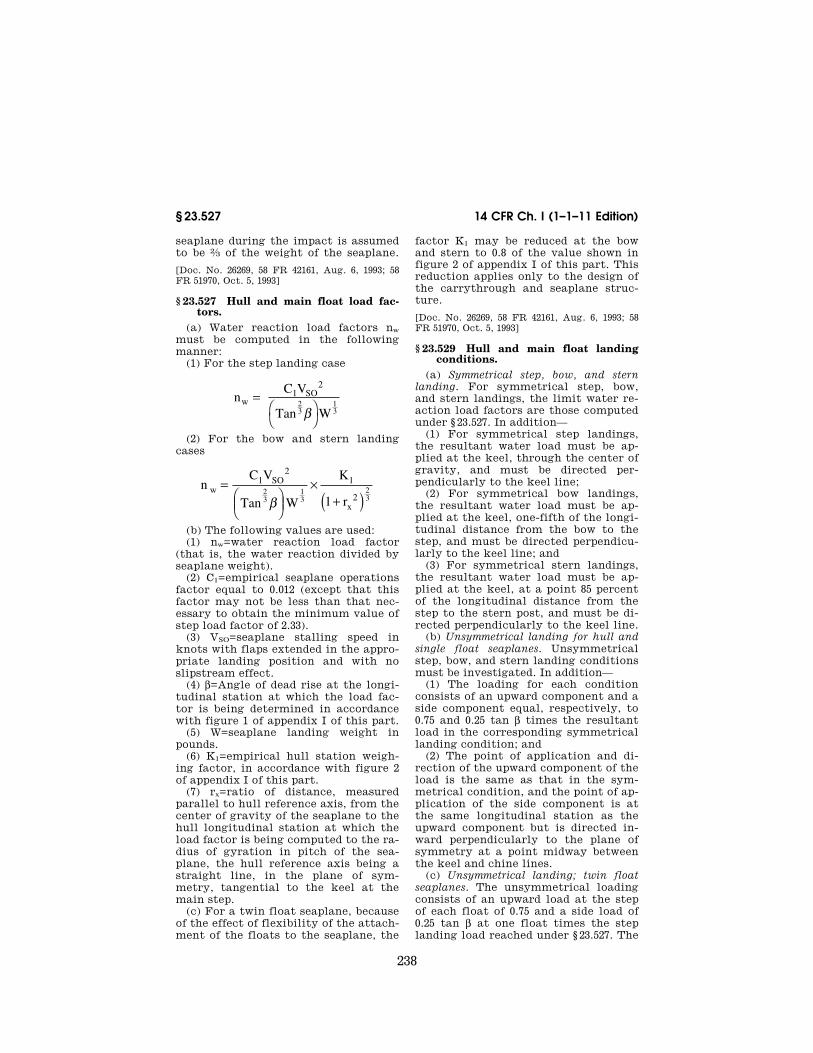
238
14 CFR Ch. I (1–1–11 Edition) § 23.527
seaplane during the impact is assumed to be 2⁄3 of the weight of the seaplane.
[Doc. No. 26269, 58 FR 42161, Aug. 6, 1993; 58 FR 51970, Oct. 5, 1993]
§ 23.527 Hull and main float load fac-tors.
(a) Water reaction load factors nw must be computed in the following manner:
(1) For the step landing case
nC V
Tan Ww
1 SO23
13
=⎛⎝
⎞⎠
2
β
(2) For the bow and stern landing cases
nC V
Tan W
K
1 rw
1 SO 1
x
23
13
23
=⎛⎝⎜
⎞⎠⎟
×+( )
2
2β
(b) The following values are used: (1) nw=water reaction load factor
(that is, the water reaction divided by seaplane weight).
(2) C1=empirical seaplane operations factor equal to 0.012 (except that this factor may not be less than that nec-essary to obtain the minimum value of step load factor of 2.33).
(3) VSO=seaplane stalling speed in knots with flaps extended in the appro-priate landing position and with no slipstream effect.
(4) b=Angle of dead rise at the longi-tudinal station at which the load fac-tor is being determined in accordance with figure 1 of appendix I of this part.
(5) W=seaplane landing weight in pounds.
(6) K1=empirical hull station weigh-ing factor, in accordance with figure 2 of appendix I of this part.
(7) rx=ratio of distance, measured parallel to hull reference axis, from the center of gravity of the seaplane to the hull longitudinal station at which the load factor is being computed to the ra-dius of gyration in pitch of the sea-plane, the hull reference axis being a straight line, in the plane of sym-metry, tangential to the keel at the main step.
(c) For a twin float seaplane, because of the effect of flexibility of the attach-ment of the floats to the seaplane, the
factor K1 may be reduced at the bow and stern to 0.8 of the value shown in figure 2 of appendix I of this part. This reduction applies only to the design of the carrythrough and seaplane struc-ture.
[Doc. No. 26269, 58 FR 42161, Aug. 6, 1993; 58 FR 51970, Oct. 5, 1993]
§ 23.529 Hull and main float landing conditions.
(a) Symmetrical step, bow, and stern landing. For symmetrical step, bow, and stern landings, the limit water re-action load factors are those computed under § 23.527. In addition—
(1) For symmetrical step landings, the resultant water load must be ap-plied at the keel, through the center of gravity, and must be directed per-pendicularly to the keel line;
(2) For symmetrical bow landings, the resultant water load must be ap-plied at the keel, one-fifth of the longi-tudinal distance from the bow to the step, and must be directed perpendicu-larly to the keel line; and
(3) For symmetrical stern landings, the resultant water load must be ap-plied at the keel, at a point 85 percent of the longitudinal distance from the step to the stern post, and must be di-rected perpendicularly to the keel line.
(b) Unsymmetrical landing for hull and single float seaplanes. Unsymmetrical step, bow, and stern landing conditions must be investigated. In addition—
(1) The loading for each condition consists of an upward component and a side component equal, respectively, to 0.75 and 0.25 tan b times the resultant load in the corresponding symmetrical landing condition; and
(2) The point of application and di-rection of the upward component of the load is the same as that in the sym-metrical condition, and the point of ap-plication of the side component is at the same longitudinal station as the upward component but is directed in-ward perpendicularly to the plane of symmetry at a point midway between the keel and chine lines.
(c) Unsymmetrical landing; twin float seaplanes. The unsymmetrical loading consists of an upward load at the step of each float of 0.75 and a side load of 0.25 tan b at one float times the step landing load reached under § 23.527. The
VerDate Mar<15>2010 14:10 Mar 01, 2011 Jkt 223043 PO 00000 Frm 00248 Fmt 8010 Sfmt 8010 Y:\SGML\223043.XXX 223043 EC
28S
E91
.004
</M
AT
H>
EC
28S
E91
.005
</M
AT
H>
ww
oods
2 on
DS
K1D
XX
6B1P
RO
D w
ith C
FR

239
Federal Aviation Administration, DOT § 23.533
side load is directed inboard, per-pendicularly to the plane of symmetry midway between the keel and chine lines of the float, at the same longitu-dinal station as the upward load.
[Doc. No. 26269, 58 FR 42161, Aug. 6, 1993]
§ 23.531 Hull and main float takeoff condition.
For the wing and its attachment to the hull or main float—
(a) The aerodynamic wing lift is as-sumed to be zero; and
(b) A downward inertia load, cor-responding to a load factor computed from the following formula, must be applied:
nC V
Tan W
TO S123
13
=⎛⎝
⎞⎠
2
β
Where—
n=inertia load factor; CTO=empirical seaplane operations factor
equal to 0.004; VS1=seaplane stalling speed (knots) at the de-
sign takeoff weight with the flaps extended in the appropriate takeoff position;
b=angle of dead rise at the main step (de-grees); and
W=design water takeoff weight in pounds.
[Doc. No. 26269, 58 FR 42161, Aug. 6, 1993]
§ 23.533 Hull and main float bottom pressures.
(a) General. The hull and main float structure, including frames and bulk-heads, stringers, and bottom plating, must be designed under this section.
(b) Local pressures. For the design of the bottom plating and stringers and their attachments to the supporting structure, the following pressure dis-tributions must be applied:
(1) For an unflared bottom, the pres-sure at the chine is 0.75 times the pres-sure at the keel, and the pressures be-tween the keel and chine vary linearly, in accordance with figure 3 of appendix I of this part. The pressure at the keel (p.s.i.) is computed as follows:
PC K V
TanK
2 2 S1
k
=2
βwhere—
Pk=pressure (p.s.i.) at the keel; C2=0.00213; K2=hull station weighing factor, in accord-
ance with figure 2 of appendix I of this part;
VS1=seaplane stalling speed (knots) at the de-sign water takeoff weight with flaps ex-tended in the appropriate takeoff position; and
bK=angle of dead rise at keel, in accordance with figure 1 of appendix I of this part.
(2) For a flared bottom, the pressure at the beginning of the flare is the same as that for an unflared bottom, and the pressure between the chine and the beginning of the flare varies lin-early, in accordance with figure 3 of ap-pendix I of this part. The pressure dis-tribution is the same as that prescribed in paragraph (b)(1) of this section for an unflared bottom except that the pressure at the chine is computed as follows:
PC K V
Tanch
3 2 S1=2
βwhere— Pch=pressure (p.s.i.) at the chine; C3=0.0016; K2=hull station weighing factor, in accord-
ance with figure 2 of appendix I of this part;
VS1=seaplane stalling speed (knots) at the de-sign water takeoff weight with flaps ex-tended in the appropriate takeoff position; and
b=angle of dead rise at appropriate station.
The area over which these pressures are applied must simulate pressures oc-curring during high localized impacts on the hull or float, but need not ex-tend over an area that would induce critical stresses in the frames or in the overall structure.
(c) Distributed pressures. For the de-sign of the frames, keel, and chine structure, the following pressure dis-tributions apply:
(1) Symmetrical pressures are com-puted as follows:
PC K V
Tan4 2 SO=
2
βwhere— P=pressure (p.s.i.); C4=0.078 C1 (with C1 computed under § 23.527); K2=hull station weighing factor, determined
in accordance with figure 2 of appendix I of this part;
VerDate Mar<15>2010 14:10 Mar 01, 2011 Jkt 223043 PO 00000 Frm 00249 Fmt 8010 Sfmt 8010 Y:\SGML\223043.XXX 223043 EC
28S
E91
.006
</M
AT
H>
EC
28S
E91
.007
</M
AT
H>
EC
28S
E91
.008
</M
AT
H>
EC
28S
E91
.009
</M
AT
H>
ww
oods
2 on
DS
K1D
XX
6B1P
RO
D w
ith C
FR

240
14 CFR Ch. I (1–1–11 Edition) § 23.535
VS0=seaplane stalling speed (knots) with landing flaps extended in the appropriate position and with no slipstream effect; and
b=angle of dead rise at appropriate station.
(2) The unsymmetrical pressure dis-tribution consists of the pressures pre-scribed in paragraph (c)(1) of this sec-tion on one side of the hull or main float centerline and one-half of that pressure on the other side of the hull or main float centerline, in accordance with figure 3 of appendix I of this part.
(3) These pressures are uniform and must be applied simultaneously over the entire hull or main float bottom. The loads obtained must be carried into the sidewall structure of the hull proper, but need not be transmitted in a fore and aft direction as shear and bending loads.
[Doc. No. 26269, 58 FR 42161, Aug. 6, 1993; 58 FR 51970, Oct. 5, 1993]
§ 23.535 Auxiliary float loads.
(a) General. Auxiliary floats and their attachments and supporting structures must be designed for the conditions prescribed in this section. In the cases specified in paragraphs (b) through (e) of this section, the prescribed water loads may be distributed over the float bottom to avoid excessive local loads, using bottom pressures not less than those prescribed in paragraph (g) of this section.
(b) Step loading. The resultant water load must be applied in the plane of symmetry of the float at a point three- fourths of the distance from the bow to the step and must be perpendicular to the keel. The resultant limit load is computed as follows, except that the value of L need not exceed three times the weight of the displaced water when the float is completely submerged:
LC V W
Tan 1 r
5 SO
Sy
23
23
23
=+( )
2
2β
where—
L=limit load (lbs.); C5=0.0053; VS0=seaplane stalling speed (knots) with
landing flaps extended in the appropriate position and with no slipstream effect;
W=seaplane design landing weight in pounds;
bs=angle of dead rise at a station 3⁄4 of the distance from the bow to the step, but need not be less than 15 degrees; and
ry=ratio of the lateral distance between the center of gravity and the plane of sym-metry of the float to the radius of gyration in roll.
(c) Bow loading. The resultant limit load must be applied in the plane of symmetry of the float at a point one- fourth of the distance from the bow to the step and must be perpendicular to the tangent to the keel line at that point. The magnitude of the resultant load is that specified in paragraph (b) of this section.
(d) Unsymmetrical step loading. The re-sultant water load consists of a compo-nent equal to 0.75 times the load speci-fied in paragraph (a) of this section and a side component equal to 0.025 tan b times the load specified in paragraph (b) of this section. The side load must be applied perpendicularly to the plane of symmetry of the float at a point midway between the keel and the chine.
(e) Unsymmetrical bow loading. The re-sultant water load consists of a compo-nent equal to 0.75 times the load speci-fied in paragraph (b) of this section and a side component equal to 0.25 tan b times the load specified in paragraph (c) of this section. The side load must be applied perpendicularly to the plane of symmetry at a point midway be-tween the keel and the chine.
(f) Immersed float condition. The re-sultant load must be applied at the centroid of the cross section of the float at a point one-third of the dis-tance from the bow to the step. The limit load components are as follows:
vertical PgV
aftC PV (KV )
2
sideC PV (KV )
2
X SO2
Y SO2
23
23
=
=
=
where—
P=mass density of water (slugs/ft.3) V=volume of float (ft.3); CX=coefficient of drag force, equal to 0.133; Cy=coefficient of side force, equal to 0.106;
VerDate Mar<15>2010 14:10 Mar 01, 2011 Jkt 223043 PO 00000 Frm 00250 Fmt 8010 Sfmt 8010 Y:\SGML\223043.XXX 223043 EC
28S
E91
.010
</M
AT
H>
EC
28S
E91
.011
</M
AT
H>
ww
oods
2 on
DS
K1D
XX
6B1P
RO
D w
ith C
FR

241
Federal Aviation Administration, DOT § 23.562
K=0.8, except that lower values may be used if it is shown that the floats are incapable of submerging at a speed of 0.8 Vso in nor-mal operations;
Vso=seaplane stalling speed (knots) with landing flaps extended in the appropriate position and with no slipstream effect; and
g=acceleration due to gravity (ft/sec2).
(g) Float bottom pressures. The float bottom pressures must be established under § 23.533, except that the value of K2 in the formulae may be taken as 1.0. The angle of dead rise to be used in de-termining the float bottom pressures is set forth in paragraph (b) of this sec-tion.
[Doc. No. 26269, 58 FR 42162, Aug. 6, 1993; 58 FR 51970, Oct. 5, 1993]
§ 23.537 Seawing loads. Seawing design loads must be based
on applicable test data.
[Doc. No. 26269, 58 FR 42163, Aug. 6, 1993]
EMERGENCY LANDING CONDITIONS
§ 23.561 General. (a) The airplane, although it may be
damaged in emergency landing condi-tions, must be designed as prescribed in this section to protect each occupant under those conditions.
(b) The structure must be designed to give each occupant every reasonable chance of escaping serious injury when—
(1) Proper use is made of the seats, safety belts, and shoulder harnesses provided for in the design;
(2) The occupant experiences the static inertia loads corresponding to the following ultimate load factors—
(i) Upward, 3.0g for normal, utility, and commuter category airplanes, or 4.5g for acrobatic category airplanes;
(ii) Forward, 9.0g; (iii) Sideward, 1.5g; and (iv) Downward, 6.0g when certifi-
cation to the emergency exit provi-sions of § 23.807(d)(4) is requested; and
(3) The items of mass within the cabin, that could injure an occupant, experience the static inertia loads cor-responding to the following ultimate load factors—
(i) Upward, 3.0g; (ii) Forward, 18.0g; and (iii) Sideward, 4.5g.
(c) Each airplane with retractable landing gear must be designed to pro-tect each occupant in a landing—
(1) With the wheels retracted; (2) With moderate descent velocity;
and (3) Assuming, in the absence of a
more rational analysis— (i) A downward ultimate inertia force
of 3 g; and (ii) A coefficient of friction of 0.5 at
the ground. (d) If it is not established that a
turnover is unlikely during an emer-gency landing, the structure must be designed to protect the occupants in a complete turnover as follows:
(1) The likelihood of a turnover may be shown by an analysis assuming the following conditions—
(i) The most adverse combination of weight and center of gravity position;
(ii) Longitudinal load factor of 9.0g; (iii) Vertical load factor of 1.0g; and (iv) For airplanes with tricycle land-
ing gear, the nose wheel strut failed with the nose contacting the ground.
(2) For determining the loads to be applied to the inverted airplane after a turnover, an upward ultimate inertia load factor of 3.0g and a coefficient of friction with the ground of 0.5 must be used.
(e) Except as provided in § 23.787(c), the supporting structure must be de-signed to restrain, under loads up to those specified in paragraph (b)(3) of this section, each item of mass that could injure an occupant if it came loose in a minor crash landing.
[Doc. No. 4080, 29 FR 17955, Dec. 18, 1964, as amended by Amdt. 23–7, 34 FR 13090, Aug. 13, 1969; Amdt. 23–24, 52 FR 34745, Sept. 14, 1987; Amdt. 23–36, 53 FR 30812, Aug. 15, 1988; Amdt. 23–46, 59 FR 25772, May 17, 1994; Amdt. 23–48, 61 FR 5147, Feb. 9, 1996]
§ 23.562 Emergency landing dynamic conditions.
(a) Each seat/restraint system for use in a normal, utility, or acrobatic cat-egory airplane must be designed to pro-tect each occupant during an emer-gency landing when—
(1) Proper use is made of seats, safety belts, and shoulder harnesses provided for in the design; and
VerDate Mar<15>2010 14:10 Mar 01, 2011 Jkt 223043 PO 00000 Frm 00251 Fmt 8010 Sfmt 8010 Y:\SGML\223043.XXX 223043ww
oods
2 on
DS
K1D
XX
6B1P
RO
D w
ith C
FR
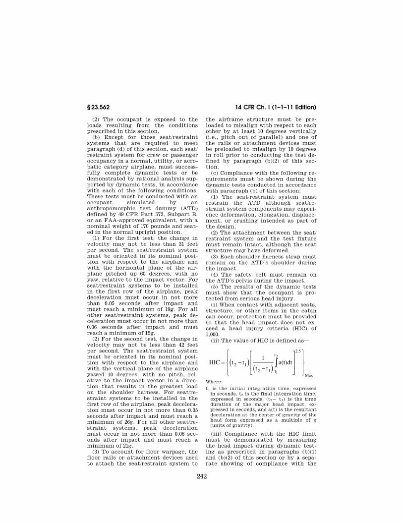
242
14 CFR Ch. I (1–1–11 Edition) § 23.562
(2) The occupant is exposed to the loads resulting from the conditions prescribed in this section.
(b) Except for those seat/restraint systems that are required to meet paragraph (d) of this section, each seat/ restraint system for crew or passenger occupancy in a normal, utility, or acro-batic category airplane, must success-fully complete dynamic tests or be demonstrated by rational analysis sup-ported by dynamic tests, in accordance with each of the following conditions. These tests must be conducted with an occupant simulated by an anthropomorphic test dummy (ATD) defined by 49 CFR Part 572, Subpart B, or an FAA-approved equivalent, with a nominal weight of 170 pounds and seat-ed in the normal upright position.
(1) For the first test, the change in velocity may not be less than 31 feet per second. The seat/restraint system must be oriented in its nominal posi-tion with respect to the airplane and with the horizontal plane of the air-plane pitched up 60 degrees, with no yaw, relative to the impact vector. For seat/restraint systems to be installed in the first row of the airplane, peak deceleration must occur in not more than 0.05 seconds after impact and must reach a minimum of 19g. For all other seat/restraint systems, peak de-celeration must occur in not more than 0.06 seconds after impact and must reach a minimum of 15g.
(2) For the second test, the change in velocity may not be less than 42 feet per second. The seat/restraint system must be oriented in its nominal posi-tion with respect to the airplane and with the vertical plane of the airplane yawed 10 degrees, with no pitch, rel-ative to the impact vector in a direc-tion that results in the greatest load on the shoulder harness. For seat/re-straint systems to be installed in the first row of the airplane, peak decelera-tion must occur in not more than 0.05 seconds after impact and must reach a minimum of 26g. For all other seat/re-straint systems, peak deceleration must occur in not more than 0.06 sec-onds after impact and must reach a minimum of 21g.
(3) To account for floor warpage, the floor rails or attachment devices used to attach the seat/restraint system to
the airframe structure must be pre-loaded to misalign with respect to each other by at least 10 degrees vertically (i.e., pitch out of parallel) and one of the rails or attachment devices must be preloaded to misalign by 10 degrees in roll prior to conducting the test de-fined by paragraph (b)(2) of this sec-tion.
(c) Compliance with the following re-quirements must be shown during the dynamic tests conducted in accordance with paragraph (b) of this section:
(1) The seat/restraint system must restrain the ATD although seat/re-straint system components may experi-ence deformation, elongation, displace-ment, or crushing intended as part of the design.
(2) The attachment between the seat/ restraint system and the test fixture must remain intact, although the seat structure may have deformed.
(3) Each shoulder harness strap must remain on the ATD’s shoulder during the impact.
(4) The safety belt must remain on the ATD’s pelvis during the impact.
(5) The results of the dynamic tests must show that the occupant is pro-tected from serious head injury.
(i) When contact with adjacent seats, structure, or other items in the cabin can occur, protection must be provided so that the head impact does not ex-ceed a head injury criteria (HIC) of 1,000.
(ii) The value of HIC is defined as—
HIC t t1
t ta(t)dt2 1
2 1 t
t2.5
Max1
2
= −( )−( )
⎡
⎣
⎢⎢
⎤
⎦
⎥⎥
⎧
⎨⎪
⎩⎪
⎫
⎬⎪
⎭⎪
∫
Where:
t1 is the initial integration time, expressed in seconds, t2 is the final integration time, expressed in seconds, (t2¥ t1) is the time duration of the major head impact, ex-pressed in seconds, and a(t) is the resultant deceleration at the center of gravity of the head form expressed as a multiple of g (units of gravity).
(iii) Compliance with the HIC limit must be demonstrated by measuring the head impact during dynamic test-ing as prescribed in paragraphs (b)(1) and (b)(2) of this section or by a sepa-rate showing of compliance with the
VerDate Mar<15>2010 14:10 Mar 01, 2011 Jkt 223043 PO 00000 Frm 00252 Fmt 8010 Sfmt 8010 Y:\SGML\223043.XXX 223043 EC
28S
E91
.012
</M
AT
H>
ww
oods
2 on
DS
K1D
XX
6B1P
RO
D w
ith C
FR
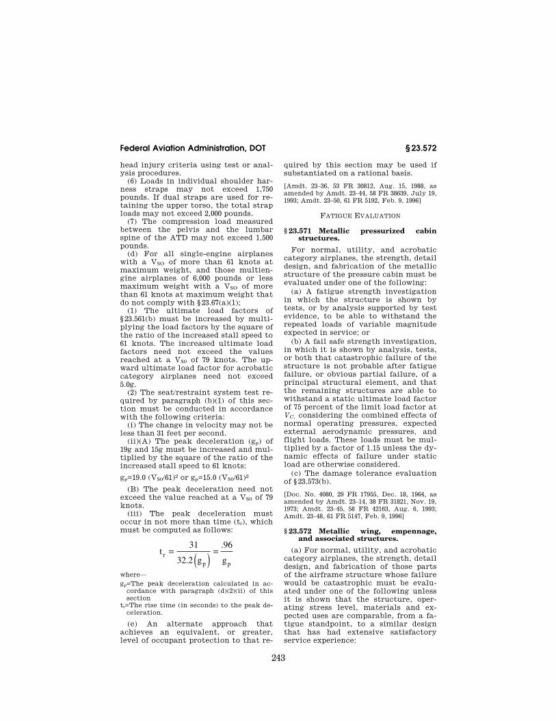
243
Federal Aviation Administration, DOT § 23.572
head injury criteria using test or anal-ysis procedures.
(6) Loads in individual shoulder har-ness straps may not exceed 1,750 pounds. If dual straps are used for re-taining the upper torso, the total strap loads may not exceed 2,000 pounds.
(7) The compression load measured between the pelvis and the lumbar spine of the ATD may not exceed 1,500 pounds.
(d) For all single-engine airplanes with a VSO of more than 61 knots at maximum weight, and those multien-gine airplanes of 6,000 pounds or less maximum weight with a VSO of more than 61 knots at maximum weight that do not comply with § 23.67(a)(1);
(1) The ultimate load factors of § 23.561(b) must be increased by multi-plying the load factors by the square of the ratio of the increased stall speed to 61 knots. The increased ultimate load factors need not exceed the values reached at a VS0 of 79 knots. The up-ward ultimate load factor for acrobatic category airplanes need not exceed 5.0g.
(2) The seat/restraint system test re-quired by paragraph (b)(1) of this sec-tion must be conducted in accordance with the following criteria:
(i) The change in velocity may not be less than 31 feet per second.
(ii)(A) The peak deceleration (gp) of 19g and 15g must be increased and mul-tiplied by the square of the ratio of the increased stall speed to 61 knots:
gp=19.0 (VS0/61)2 or gp=15.0 (VS0/61)2
(B) The peak deceleration need not exceed the value reached at a VS0 of 79 knots.
(iii) The peak deceleration must occur in not more than time (tr), which must be computed as follows:
t31
32.2 g
.96
gr
p p
= ( ) =
where— gp=The peak deceleration calculated in ac-
cordance with paragraph (d)(2)(ii) of this section
tr=The rise time (in seconds) to the peak de-celeration.
(e) An alternate approach that achieves an equivalent, or greater, level of occupant protection to that re-
quired by this section may be used if substantiated on a rational basis.
[Amdt. 23–36, 53 FR 30812, Aug. 15, 1988, as amended by Amdt. 23–44, 58 FR 38639, July 19, 1993; Amdt. 23–50, 61 FR 5192, Feb. 9, 1996]
FATIGUE EVALUATION
§ 23.571 Metallic pressurized cabin structures.
For normal, utility, and acrobatic category airplanes, the strength, detail design, and fabrication of the metallic structure of the pressure cabin must be evaluated under one of the following:
(a) A fatigue strength investigation in which the structure is shown by tests, or by analysis supported by test evidence, to be able to withstand the repeated loads of variable magnitude expected in service; or
(b) A fail safe strength investigation, in which it is shown by analysis, tests, or both that catastrophic failure of the structure is not probable after fatigue failure, or obvious partial failure, of a principal structural element, and that the remaining structures are able to withstand a static ultimate load factor of 75 percent of the limit load factor at VC, considering the combined effects of normal operating pressures, expected external aerodynamic pressures, and flight loads. These loads must be mul-tiplied by a factor of 1.15 unless the dy-namic effects of failure under static load are otherwise considered.
(c) The damage tolerance evaluation of § 23.573(b).
[Doc. No. 4080, 29 FR 17955, Dec. 18, 1964, as amended by Amdt. 23–14, 38 FR 31821, Nov. 19, 1973; Amdt. 23–45, 58 FR 42163, Aug. 6, 1993; Amdt. 23–48, 61 FR 5147, Feb. 9, 1996]
§ 23.572 Metallic wing, empennage, and associated structures.
(a) For normal, utility, and acrobatic category airplanes, the strength, detail design, and fabrication of those parts of the airframe structure whose failure would be catastrophic must be evalu-ated under one of the following unless it is shown that the structure, oper-ating stress level, materials and ex-pected uses are comparable, from a fa-tigue standpoint, to a similar design that has had extensive satisfactory service experience:
VerDate Mar<15>2010 14:10 Mar 01, 2011 Jkt 223043 PO 00000 Frm 00253 Fmt 8010 Sfmt 8010 Y:\SGML\223043.XXX 223043 EC
28S
E91
.013
</M
AT
H>
ww
oods
2 on
DS
K1D
XX
6B1P
RO
D w
ith C
FR
244
14 CFR Ch. I (1–1–11 Edition) § 23.573
(1) A fatigue strength investigation in which the structure is shown by tests, or by analysis supported by test evidence, to be able to withstand the repeated loads of variable magnitude expected in service; or
(2) A fail-safe strength investigation in which it is shown by analysis, tests, or both, that catastrophic failure of the structure is not probable after fa-tigue failure, or obvious partial failure, of a principal structural element, and that the remaining structure is able to withstand a static ultimate load factor of 75 percent of the critical limit load factor at Vc. These loads must be mul-tiplied by a factor of 1.15 unless the dy-namic effects of failure under static load are otherwise considered.
(3) The damage tolerance evaluation of § 23.573(b).
(b) Each evaluation required by this section must—
(1) Include typical loading spectra (e.g. taxi, ground-air-ground cycles, maneuver, gust);
(2) Account for any significant effects due to the mutual influence of aero-dynamic surfaces; and
(3) Consider any significant effects from propeller slipstream loading, and buffet from vortex impingements.
[Amdt. 23–7, 34 FR 13090, Aug. 13, 1969, as amended by Amdt. 23–14, 38 FR 31821, Nov. 19, 1973; Amdt. 23–34, 52 FR 1830, Jan. 15, 1987; Amdt. 23–38, 54 FR 39511, Sept. 26, 1989; Amdt. 23–45, 58 FR 42163, Aug. 6, 1993; Amdt. 23–48, 61 FR 5147, Feb. 9, 1996]
§ 23.573 Damage tolerance and fatigue evaluation of structure.
(a) Composite airframe structure. Com-posite airframe structure must be eval-uated under this paragraph instead of §§ 23.571 and 23.572. The applicant must evaluate the composite airframe struc-ture, the failure of which would result in catastrophic loss of the airplane, in each wing (including canards, tandem wings, and winglets), empennage, their carrythrough and attaching structure, moveable control surfaces and their at-taching structure fuselage, and pres-sure cabin using the damage-tolerance criteria prescribed in paragraphs (a)(1) through (a)(4) of this section unless shown to be impractical. If the appli-cant establishes that damage-tolerance criteria is impractical for a particular
structure, the structure must be evalu-ated in accordance with paragraphs (a)(1) and (a)(6) of this section. Where bonded joints are used, the structure must also be evaluated in accordance with paragraph (a)(5) of this section. The effects of material variability and environmental conditions on the strength and durability properties of the composite materials must be ac-counted for in the evaluations required by this section.
(1) It must be demonstrated by tests, or by analysis supported by tests, that the structure is capable of carrying ul-timate load with damage up to the threshold of detectability considering the inspection procedures employed.
(2) The growth rate or no-growth of damage that may occur from fatigue, corrosion, manufacturing flaws or im-pact damage, under repeated loads ex-pected in service, must be established by tests or analysis supported by tests.
(3) The structure must be shown by residual strength tests, or analysis sup-ported by residual strength tests, to be able to withstand critical limit flight loads, considered as ultimate loads, with the extent of detectable damage consistent with the results of the dam-age tolerance evaluations. For pressur-ized cabins, the following loads must be withstood:
(i) Critical limit flight loads with the combined effects of normal operating pressure and expected external aero-dynamic pressures.
(ii) The expected external aero-dynamic pressures in 1g flight com-bined with a cabin differential pressure equal to 1.1 times the normal operating differential pressure without any other load.
(4) The damage growth, between ini-tial detectability and the value se-lected for residual strength demonstra-tions, factored to obtain inspection in-tervals, must allow development of an inspection program suitable for appli-cation by operation and maintenance personnel.
(5) For any bonded joint, the failure of which would result in catastrophic loss of the airplane, the limit load ca-pacity must be substantiated by one of the following methods—
VerDate Mar<15>2010 14:10 Mar 01, 2011 Jkt 223043 PO 00000 Frm 00254 Fmt 8010 Sfmt 8010 Y:\SGML\223043.XXX 223043ww
oods
2 on
DS
K1D
XX
6B1P
RO
D w
ith C
FR

245
Federal Aviation Administration, DOT § 23.575
(i) The maximum disbonds of each bonded joint consistent with the capa-bility to withstand the loads in para-graph (a)(3) of this section must be de-termined by analysis, tests, or both. Disbonds of each bonded joint greater than this must be prevented by design features; or
(ii) Proof testing must be conducted on each production article that will apply the critical limit design load to each critical bonded joint; or
(iii) Repeatable and reliable non-de-structive inspection techniques must be established that ensure the strength of each joint.
(6) Structural components for which the damage tolerance method is shown to be impractical must be shown by component fatigue tests, or analysis supported by tests, to be able to with-stand the repeated loads of variable magnitude expected in service. Suffi-cient component, subcomponent, ele-ment, or coupon tests must be done to establish the fatigue scatter factor and the environmental effects. Damage up to the threshold of detectability and ultimate load residual strength capa-bility must be considered in the dem-onstration.
(b) Metallic airframe structure. If the applicant elects to use § 23.571(c) or § 23.572(a)(3), then the damage tolerance evaluation must include a determina-tion of the probable locations and modes of damage due to fatigue, corro-sion, or accidental damage. Damage at multiple sites due to fatigue must be included where the design is such that this type of damage can be expected to occur. The evaluation must incor-porate repeated load and static anal-yses supported by test evidence. The extent of damage for residual strength evaluation at any time within the operational life of the airplane must be consistent with the initial detect-ability and subsequent growth under repeated loads. The residual strength evaluation must show that the remain-ing structure is able to withstand crit-ical limit flight loads, considered as ul-timate, with the extent of detectable damage consistent with the results of the damage tolerance evaluations. For pressurized cabins, the following load must be withstood:
(1) The normal operating differential pressure combined with the expected external aerodynamic pressures applied simultaneously with the flight loading conditions specified in this part, and
(2) The expected external aero-dynamic pressures in 1g flight com-bined with a cabin differential pressure equal to 1.1 times the normal operating differential pressure without any other load.
[Doc. No. 26269, 58 FR 42163, Aug. 6, 1993; 58 FR 51970, Oct. 5, 1993, as amended by Amdt. 23–48, 61 FR 5147, Feb. 9, 1996; 73 FR 19746, Apr. 11, 2008]
§ 23.574 Metallic damage tolerance and fatigue evaluation of commuter cat-egory airplanes.
For commuter category airplanes— (a) Metallic damage tolerance. An eval-
uation of the strength, detail design, and fabrication must show that cata-strophic failure due to fatigue, corro-sion, defects, or damage will be avoided throughout the operational life of the airplane. This evaluation must be con-ducted in accordance with the provi-sions of § 23.573, except as specified in paragraph (b) of this section, for each part of the structure that could con-tribute to a catastrophic failure.
(b) Fatigue (safe-life) evaluation. Com-pliance with the damage tolerance re-quirements of paragraph (a) of this sec-tion is not required if the applicant es-tablishes that the application of those requirements is impractical for a par-ticular structure. This structure must be shown, by analysis supported by test evidence, to be able to withstand the repeated loads of variable magnitude expected during its service life without detectable cracks. Appropriate safe-life scatter factors must be applied.
[Doc. No. 27805, 61 FR 5148, Feb. 9, 1996]
§ 23.575 Inspections and other proce-dures.
Each inspection or other procedure, based on an evaluation required by §§ 23.571, 23.572, 23.573 or 23.574, must be established to prevent catastrophic failure and must be included in the Limitations Section of the Instructions for Continued Airworthiness required by § 23.1529.
[Doc. No. 27805, 61 FR 5148, Feb. 9, 1996]
VerDate Mar<15>2010 14:10 Mar 01, 2011 Jkt 223043 PO 00000 Frm 00255 Fmt 8010 Sfmt 8010 Y:\SGML\223043.XXX 223043ww
oods
2 on
DS
K1D
XX
6B1P
RO
D w
ith C
FR
246
14 CFR Ch. I (1–1–11 Edition) § 23.601
Subpart D—Design and Construction
§ 23.601 General. The suitability of each questionable
design detail and part having an impor-tant bearing on safety in operations, must be established by tests.
§ 23.603 Materials and workmanship. (a) The suitability and durability of
materials used for parts, the failure of which could adversely affect safety, must—
(1) Be established by experience or tests;
(2) Meet approved specifications that ensure their having the strength and other properties assumed in the design data; and
(3) Take into account the effects of environmental conditions, such as tem-perature and humidity, expected in service.
(b) Workmanship must be of a high standard.
[Doc. No. 4080, 29 FR 17955, Dec. 18, 1964, as amended by Amdt. 23–17, 41 FR 55464, Dec. 20, 1976; Amdt. 23–23, 43 FR 50592, Oct. 10, 1978]
§ 23.605 Fabrication methods. (a) The methods of fabrication used
must produce consistently sound struc-tures. If a fabrication process (such as gluing, spot welding, or heat-treating) requires close control to reach this ob-jective, the process must be performed under an approved process specifica-tion.
(b) Each new aircraft fabrication method must be substantiated by a test program.
[Doc. No. 4080, 29 FR 17955, Dec. 18, 1964; 30 FR 258, Jan. 9, 1965, as amended by Amdt. 23– 23, 43 FR 50592, Oct. 10, 1978]
§ 23.607 Fasteners. (a) Each removable fastener must in-
corporate two retaining devices if the loss of such fastener would preclude continued safe flight and landing.
(b) Fasteners and their locking de-vices must not be adversely affected by the environmental conditions associ-ated with the particular installation.
(c) No self-locking nut may be used on any bolt subject to rotation in oper-ation unless a non-friction locking de-
vice is used in addition to the self-lock-ing device.
[Doc. No. 27805, 61 FR 5148, Feb. 9, 1996]
§ 23.609 Protection of structure.
Each part of the structure must— (a) Be suitably protected against de-
terioration or loss of strength in serv-ice due to any cause, including—
(1) Weathering; (2) Corrosion; and (3) Abrasion; and (b) Have adequate provisions for ven-
tilation and drainage.
§ 23.611 Accessibility provisions.
For each part that requires mainte-nance, inspection, or other servicing, appropriate means must be incor-porated into the aircraft design to allow such servicing to be accom-plished.
[Doc. No. 27805, 61 FR 5148, Feb. 9, 1996]
§ 23.613 Material strength properties and design values.
(a) Material strength properties must be based on enough tests of material meeting specifications to establish de-sign values on a statistical basis.
(b) Design values must be chosen to minimize the probability of structural failure due to material variability. Ex-cept as provided in paragraph (e) of this section, compliance with this paragraph must be shown by selecting design values that ensure material strength with the following prob-ability:
(1) Where applied loads are eventu-ally distributed through a single mem-ber within an assembly, the failure of which would result in loss of structural integrity of the component; 99 percent probability with 95 percent confidence.
(2) For redundant structure, in which the failure of individual elements would result in applied loads being safely distributed to other load car-rying members; 90 percent probability with 95 percent confidence.
(c) The effects of temperature on al-lowable stresses used for design in an essential component or structure must be considered where thermal effects are significant under normal operating conditions.
VerDate Mar<15>2010 14:10 Mar 01, 2011 Jkt 223043 PO 00000 Frm 00256 Fmt 8010 Sfmt 8010 Y:\SGML\223043.XXX 223043ww
oods
2 on
DS
K1D
XX
6B1P
RO
D w
ith C
FR
247
Federal Aviation Administration, DOT § 23.621
(d) The design of the structure must minimize the probability of cata-strophic fatigue failure, particularly at points of stress concentration.
(e) Design values greater than the guaranteed minimums required by this section may be used where only guar-anteed minimum values are normally allowed if a ‘‘premium selection’’ of the material is made in which a specimen of each individual item is tested before use to determine that the actual strength properties of that particular item will equal or exceed those used in design.
[Doc. No. 4080, 29 FR 17955, Dec. 18, 1964; 30 FR 258, Jan. 9, 1965, as amended by Amdt. 23– 23, 43 FR 50592, Oct. 30, 1978; Amdt. 23–45, 58 FR 42163, Aug. 6, 1993]
§ 23.619 Special factors. The factor of safety prescribed in
§ 23.303 must be multiplied by the high-est pertinent special factors of safety prescribed in §§ 23.621 through 23.625 for each part of the structure whose strength is—
(a) Uncertain; (b) Likely to deteriorate in service
before normal replacement; or (c) Subject to appreciable variability
because of uncertainties in manufac-turing processes or inspection methods.
[Amdt. 23–7, 34 FR 13091, Aug. 13, 1969]
§ 23.621 Casting factors. (a) General. The factors, tests, and in-
spections specified in paragraphs (b) through (d) of this section must be ap-plied in addition to those necessary to establish foundry quality control. The inspections must meet approved speci-fications. Paragraphs (c) and (d) of this section apply to any structural cast-ings except castings that are pressure tested as parts of hydraulic or other fluid systems and do not support struc-tural loads.
(b) Bearing stresses and surfaces. The casting factors specified in paragraphs (c) and (d) of this section—
(1) Need not exceed 1.25 with respect to bearing stresses regardless of the method of inspection used; and
(2) Need not be used with respect to the bearing surfaces of a part whose bearing factor is larger than the appli-cable casting factor.
(c) Critical castings. For each casting whose failure would preclude continued safe flight and landing of the airplane or result in serious injury to occu-pants, the following apply:
(1) Each critical casting must ei-ther—
(i) Have a casting factor of not less than 1.25 and receive 100 percent in-spection by visual, radiographic, and either magnetic particle, penetrant or other approved equivalent non-destruc-tive inspection method; or
(ii) Have a casting factor of not less than 2.0 and receive 100 percent visual inspection and 100 percent approved non-destructive inspection. When an approved quality control procedure is established and an acceptable statis-tical analysis supports reduction, non- destructive inspection may be reduced from 100 percent, and applied on a sam-pling basis.
(2) For each critical casting with a casting factor less than 1.50, three sam-ple castings must be static tested and shown to meet—
(i) The strength requirements of § 23.305 at an ultimate load cor-responding to a casting factor of 1.25; and
(ii) The deformation requirements of § 23.305 at a load of 1.15 times the limit load.
(3) Examples of these castings are structural attachment fittings, parts of flight control systems, control surface hinges and balance weight attach-ments, seat, berth, safety belt, and fuel and oil tank supports and attachments, and cabin pressure valves.
(d) Non-critical castings. For each casting other than those specified in paragraph (c) or (e) of this section, the following apply:
(1) Except as provided in paragraphs (d)(2) and (3) of this section, the casting factors and corresponding inspections must meet the following table:
Casting factor Inspection
2.0 or more .................... 100 percent visual. Less than 2.0 but more
than 1.5.100 percent visual, and magnetic
particle or penetrant or equiva-lent nondestructive inspection methods.
1.25 through 1.50 .......... 100 percent visual, magnetic par-ticle or penetrant, and radio-graphic, or approved equivalent nondestructive inspection meth-ods.
VerDate Mar<15>2010 14:10 Mar 01, 2011 Jkt 223043 PO 00000 Frm 00257 Fmt 8010 Sfmt 8010 Y:\SGML\223043.XXX 223043ww
oods
2 on
DS
K1D
XX
6B1P
RO
D w
ith C
FR

248
14 CFR Ch. I (1–1–11 Edition) § 23.623
(2) The percentage of castings in-spected by nonvisual methods may be reduced below that specified in sub-paragraph (d)(1) of this section when an approved quality control procedure is established.
(3) For castings procured to a speci-fication that guarantees the mechan-ical properties of the material in the casting and provides for demonstration of these properties by test of coupons cut from the castings on a sampling basis—
(i) A casting factor of 1.0 may be used; and
(ii) The castings must be inspected as provided in paragraph (d)(1) of this sec-tion for casting factors of ‘‘1.25 through 1.50’’ and tested under paragraph (c)(2) of this section.
(e) Non-structural castings. Castings used for non-structural purposes do not require evaluation, testing or close in-spection.
[Doc. No. 4080, 29 FR 17955, Dec. 18, 1964, as amended by Amdt. 23–45, 58 FR 42164, Aug. 6, 1993]
§ 23.623 Bearing factors. (a) Each part that has clearance (free
fit), and that is subject to pounding or vibration, must have a bearing factor large enough to provide for the effects of normal relative motion.
(b) For control surface hinges and control system joints, compliance with the factors prescribed in §§ 23.657 and 23.693, respectively, meets paragraph (a) of this section.
[Amdt. 23–7, 34 FR 13091, Aug. 13, 1969]
§ 23.625 Fitting factors. For each fitting (a part or terminal
used to join one structural member to another), the following apply:
(a) For each fitting whose strength is not proven by limit and ultimate load tests in which actual stress conditions are simulated in the fitting and sur-rounding structures, a fitting factor of at least 1.15 must be applied to each part of—
(1) The fitting; (2) The means of attachment; and (3) The bearing on the joined mem-
bers. (b) No fitting factor need be used for
joint designs based on comprehensive
test data (such as continuous joints in metal plating, welded joints, and scarf joints in wood).
(c) For each integral fitting, the part must be treated as a fitting up to the point at which the section properties become typical of the member.
(d) For each seat, berth, safety belt, and harness, its attachment to the structure must be shown, by analysis, tests, or both, to be able to withstand the inertia forces prescribed in § 23.561 multiplied by a fitting factor of 1.33.
[Doc. No. 4080, 29 FR 17955, Dec. 18, 1964, as amended by Amdt. 23–7, 34 FR 13091, Aug. 13, 1969]
§ 23.627 Fatigue strength.
The structure must be designed, as far as practicable, to avoid points of stress concentration where variable stresses above the fatigue limit are likely to occur in normal service.
§ 23.629 Flutter.
(a) It must be shown by the methods of paragraph (b) and either paragraph (c) or (d) of this section, that the air-plane is free from flutter, control re-versal, and divergence for any condi-tion of operation within the limit V-n envelope and at all speeds up to the speed specified for the selected method. In addition—
(1) Adequate tolerances must be es-tablished for quantities which affect flutter, including speed, damping, mass balance, and control system stiffness; and
(2) The natural frequencies of main structural components must be deter-mined by vibration tests or other ap-proved methods.
(b) Flight flutter tests must be made to show that the airplane is free from flutter, control reversal and divergence and to show that—
(1) Proper and adequate attempts to induce flutter have been made within the speed range up to VD;
(2) The vibratory response of the structure during the test indicates freedom from flutter;
(3) A proper margin of damping exists at VD; and
(4) There is no large and rapid reduc-tion in damping as VD is approached.
VerDate Mar<15>2010 14:10 Mar 01, 2011 Jkt 223043 PO 00000 Frm 00258 Fmt 8010 Sfmt 8010 Y:\SGML\223043.XXX 223043ww
oods
2 on
DS
K1D
XX
6B1P
RO
D w
ith C
FR
249
Federal Aviation Administration, DOT § 23.655
(c) Any rational analysis used to pre-dict freedom from flutter, control re-versal and divergence must cover all speeds up to 1.2 VD.
(d) Compliance with the rigidity and mass balance criteria (pages 4–12), in Airframe and Equipment Engineering Report No. 45 (as corrected) ‘‘Simplified Flutter Prevention Criteria’’ (published by the Federal Aviation Administra-tion) may be accomplished to show that the airplane is free from flutter, control reversal, or divergence if—
(1) VD/MD for the airplane is less than 260 knots (EAS) and less than Mach 0.5,
(2) The wing and aileron flutter pre-vention criteria, as represented by the wing torsional stiffness and aileron balance criteria, are limited in use to airplanes without large mass con-centrations (such as engines, floats, or fuel tanks in outer wing panels) along the wing span, and
(3) The airplane— (i) Does not have a T-tail or other un-
conventional tail configurations; (ii) Does not have unusual mass dis-
tributions or other unconventional de-sign features that affect the applica-bility of the criteria, and
(iii) Has fixed-fin and fixed-stabilizer surfaces.
(e) For turbopropeller-powered air-planes, the dynamic evaluation must include—
(1) Whirl mode degree of freedom which takes into account the stability of the plane of rotation of the propeller and significant elastic, inertial, and aerodynamic forces, and
(2) Propeller, engine, engine mount, and airplane structure stiffness and damping variations appropriate to the particular configuration.
(f) Freedom from flutter, control re-versal, and divergence up to VD/MD must be shown as follows:
(1) For airplanes that meet the cri-teria of paragraphs (d)(1) through (d)(3) of this section, after the failure, mal-function, or disconnection of any single element in any tab control system.
(2) For airplanes other than those de-scribed in paragraph (f)(1) of this sec-tion, after the failure, malfunction, or disconnection of any single element in the primary flight control system, any tab control system, or any flutter damper.
(g) For airplanes showing compliance with the fail-safe criteria of §§ 23.571 and 23.572, the airplane must be shown by analysis to be free from flutter up to VD/MD after fatigue failure, or obvi-ous partial failure, of a principal struc-tural element.
(h) For airplanes showing compliance with the damage tolerance criteria of § 23.573, the airplane must be shown by analysis to be free from flutter up to VD/MD with the extent of damage for which residual strength is dem-onstrated.
(i) For modifications to the type de-sign that could affect the flutter char-acteristics, compliance with paragraph (a) of this section must be shown, ex-cept that analysis based on previously approved data may be used alone to show freedom from flutter, control re-versal and divergence, for all speeds up to the speed specified for the selected method.
[Amdt. 23–23, 43 FR 50592, Oct. 30, 1978, as amended by Amdt. 23–31, 49 FR 46867, Nov. 28, 1984; Amdt. 23–45, 58 FR 42164, Aug. 6, 1993; 58 FR 51970, Oct. 5, 1993; Amdt. 23–48, 61 FR 5148, Feb. 9, 1996]
WINGS
§ 23.641 Proof of strength.
The strength of stressed-skin wings must be proven by load tests or by combined structural analysis and load tests.
CONTROL SURFACES
§ 23.651 Proof of strength.
(a) Limit load tests of control sur-faces are required. These tests must in-clude the horn or fitting to which the control system is attached.
(b) In structural analyses, rigging loads due to wire bracing must be ac-counted for in a rational or conserv-ative manner.
§ 23.655 Installation.
(a) Movable surfaces must be in-stalled so that there is no interference between any surfaces, their bracing, or adjacent fixed structure, when one sur-face is held in its most critical clear-ance positions and the others are oper-ated through their full movement.
VerDate Mar<15>2010 14:10 Mar 01, 2011 Jkt 223043 PO 00000 Frm 00259 Fmt 8010 Sfmt 8010 Y:\SGML\223043.XXX 223043ww
oods
2 on
DS
K1D
XX
6B1P
RO
D w
ith C
FR

250
14 CFR Ch. I (1–1–11 Edition) § 23.657
(b) If an adjustable stabilizer is used, it must have stops that will limit its range of travel to that allowing safe flight and landing.
[Doc. No. 4080, 29 FR 17955, Dec. 18, 1964, as amended by Amdt. 23–45, 58 FR 42164, Aug. 6, 1993]
§ 23.657 Hinges. (a) Control surface hinges, except
ball and roller bearing hinges, must have a factor of safety of not less than 6.67 with respect to the ultimate bear-ing strength of the softest material used as a bearing.
(b) For ball or roller bearing hinges, the approved rating of the bearing may not be exceeded.
[Doc. No. 4080, 29 FR 17955, Dec. 18, 1964, as amended by Amdt. 23–48, 61 FR 5148, Feb. 9, 1996]
§ 23.659 Mass balance. The supporting structure and the at-
tachment of concentrated mass bal-ance weights used on control surfaces must be designed for—
(a) 24 g normal to the plane of the control surface;
(b) 12 g fore and aft; and (c) 12 g parallel to the hinge line.
CONTROL SYSTEMS
§ 23.671 General. (a) Each control must operate easily,
smoothly, and positively enough to allow proper performance of its func-tions.
(b) Controls must be arranged and identified to provide for convenience in operation and to prevent the possi-bility of confusion and subsequent in-advertent operation.
§ 23.672 Stability augmentation and automatic and power-operated sys-tems.
If the functioning of stability aug-mentation or other automatic or power-operated systems is necessary to show compliance with the flight char-acteristics requirements of this part, such systems must comply with § 23.671 and the following:
(a) A warning, which is clearly dis-tinguishable to the pilot under ex-pected flight conditions without re-quiring the pilot’s attention, must be
provided for any failure in the stability augmentation system or in any other automatic or power-operated system that could result in an unsafe condi-tion if the pilot was not aware of the failure. Warning systems must not ac-tivate the control system.
(b) The design of the stability aug-mentation system or of any other auto-matic or power-operated system must permit initial counteraction of failures without requiring exceptional pilot skill or strength, by either the deacti-vation of the system or a failed portion thereof, or by overriding the failure by movement of the flight controls in the normal sense.
(c) It must be shown that, after any single failure of the stability aug-mentation system or any other auto-matic or power-operated system—
(1) The airplane is safely controllable when the failure or malfunction occurs at any speed or altitude within the ap-proved operating limitations that is critical for the type of failure being considered;
(2) The controllability and maneuver-ability requirements of this part are met within a practical operational flight envelope (for example, speed, al-titude, normal acceleration, and air-plane configuration) that is described in the Airplane Flight Manual (AFM); and
(3) The trim, stability, and stall char-acteristics are not impaired below a level needed to permit continued safe flight and landing.
[Doc. No. 26269, 58 FR 42164, Aug. 6, 1993]
§ 23.673 Primary flight controls. Primary flight controls are those
used by the pilot for the immediate control of pitch, roll, and yaw.
[Doc. No. 4080, 29 FR 17955, Dec. 18, 1964, as amended by Amdt. 23–48, 61 FR 5148, Feb. 9, 1996]
§ 23.675 Stops. (a) Each control system must have
stops that positively limit the range of motion of each movable aerodynamic surface controlled by the system.
(b) Each stop must be located so that wear, slackness, or takeup adjustments will not adversely affect the control characteristics of the airplane because
VerDate Mar<15>2010 14:10 Mar 01, 2011 Jkt 223043 PO 00000 Frm 00260 Fmt 8010 Sfmt 8010 Y:\SGML\223043.XXX 223043ww
oods
2 on
DS
K1D
XX
6B1P
RO
D w
ith C
FR
251
Federal Aviation Administration, DOT § 23.683
of a change in the range of surface travel.
(c) Each stop must be able to with-stand any loads corresponding to the design conditions for the control sys-tem.
[Amdt. 23–17, 41 FR 55464, Dec. 20, 1976]
§ 23.677 Trim systems. (a) Proper precautions must be taken
to prevent inadvertent, improper, or abrupt trim tab operation. There must be means near the trim control to indi-cate to the pilot the direction of trim control movement relative to airplane motion. In addition, there must be means to indicate to the pilot the posi-tion of the trim device with respect to both the range of adjustment and, in the case of lateral and directional trim, the neutral position. This means must be visible to the pilot and must be located and designed to prevent con-fusion. The pitch trim indicator must be clearly marked with a position or range within which it has been dem-onstrated that take-off is safe for all center of gravity positions and each flap position approved for takeoff.
(b) Trimming devices must be de-signed so that, when any one con-necting or transmitting element in the primary flight control system fails, adequate control for safe flight and landing is available with—
(1) For single-engine airplanes, the longitudinal trimming devices; or
(2) For multiengine airplanes, the longitudinal and directional trimming devices.
(c) Tab controls must be irreversible unless the tab is properly balanced and has no unsafe flutter characteristics. Irreversible tab systems must have adequate rigidity and reliability in the portion of the system from the tab to the attachment of the irreversible unit to the airplane structure.
(d) It must be demonstrated that the airplane is safely controllable and that the pilot can perform all maneuvers and operations necessary to effect a safe landing following any probable powered trim system runaway that reasonably might be expected in serv-ice, allowing for appropriate time delay after pilot recognition of the trim system runaway. The demonstra-tion must be conducted at critical air-
plane weights and center of gravity po-sitions.
[Doc. No. 4080, 29 FR 17955, Dec. 18, 1964, as amended by Amdt. 23–7, 34 FR 13091, Aug. 13, 1969; Amdt. 23–34, 52 FR 1830, Jan. 15, 1987; Amdt. 23–42, 56 FR 353, Jan. 3, 1991; Amdt. 23– 49, 61 FR 5165, Feb. 9, 1996]
§ 23.679 Control system locks. If there is a device to lock the con-
trol system on the ground or water: (a) There must be a means to— (1) Give unmistakable warning to the
pilot when lock is engaged; or (2) Automatically disengage the de-
vice when the pilot operates the pri-mary flight controls in a normal man-ner.
(b) The device must be installed to limit the operation of the airplane so that, when the device is engaged, the pilot receives unmistakable warning at the start of the takeoff.
(c) The device must have a means to preclude the possibility of it becoming inadvertently engaged in flight.
[Doc. No. 26269, 58 FR 42164, Aug. 6, 1993]
§ 23.681 Limit load static tests. (a) Compliance with the limit load
requirements of this part must be shown by tests in which—
(1) The direction of the test loads produces the most severe loading in the control system; and
(2) Each fitting, pulley, and bracket used in attaching the system to the main structure is included.
(b) Compliance must be shown (by analyses or individual load tests) with the special factor requirements for control system joints subject to angu-lar motion.
§ 23.683 Operation tests. (a) It must be shown by operation
tests that, when the controls are oper-ated from the pilot compartment with the system loaded as prescribed in paragraph (b) of this section, the sys-tem is free from—
(1) Jamming; (2) Excessive friction; and (3) Excessive deflection. (b) The prescribed test loads are— (1) For the entire system, loads cor-
responding to the limit airloads on the appropriate surface, or the limit pilot
VerDate Mar<15>2010 14:10 Mar 01, 2011 Jkt 223043 PO 00000 Frm 00261 Fmt 8010 Sfmt 8010 Y:\SGML\223043.XXX 223043ww
oods
2 on
DS
K1D
XX
6B1P
RO
D w
ith C
FR
252
14 CFR Ch. I (1–1–11 Edition) § 23.685
forces in § 23.397(b), whichever are less; and
(2) For secondary controls, loads not less than those corresponding to the maximum pilot effort established under § 23.405.
[Doc. No. 4080, 29 FR 17955, Dec. 18, 1964, as amended by Amdt. 23–7, 34 FR 13091, Aug. 13, 1969]
§ 23.685 Control system details. (a) Each detail of each control sys-
tem must be designed and installed to prevent jamming, chafing, and inter-ference from cargo, passengers, loose objects, or the freezing of moisture.
(b) There must be means in the cock-pit to prevent the entry of foreign ob-jects into places where they would jam the system.
(c) There must be means to prevent the slapping of cables or tubes against other parts.
(d) Each element of the flight control system must have design features, or must be distinctively and permanently marked, to minimize the possibility of incorrect assembly that could result in malfunctioning of the control system.
[Doc. No. 4080, 29 FR 17955, Dec. 18, 1964, as amended by Amdt. 23–17, 41 FR 55464, Dec. 20, 1976]
§ 23.687 Spring devices. The reliability of any spring device
used in the control system must be es-tablished by tests simulating service conditions unless failure of the spring will not cause flutter or unsafe flight characteristics.
§ 23.689 Cable systems. (a) Each cable, cable fitting, turn-
buckle, splice, and pulley used must meet approved specifications. In addi-tion—
(1) No cable smaller than 1⁄8 inch di-ameter may be used in primary control systems;
(2) Each cable system must be de-signed so that there will be no haz-ardous change in cable tension throughout the range of travel under operating conditions and temperature variations; and
(3) There must be means for visual inspection at each fairlead, pulley, ter-minal, and turnbuckle.
(b) Each kind and size of pulley must correspond to the cable with which it is used. Each pulley must have closely fitted guards to prevent the cables from being misplaced or fouled, even when slack. Each pulley must lie in the plane passing through the cable so that the cable does not rub against the pul-ley flange.
(c) Fairleads must be installed so that they do not cause a change in cable direction of more than three de-grees.
(d) Clevis pins subject to load or mo-tion and retained only by cotter pins may not be used in the control system.
(e) Turnbuckles must be attached to parts having angular motion in a man-ner that will positively prevent binding throughout the range of travel.
(f) Tab control cables are not part of the primary control system and may be less than 1⁄8 inch diameter in airplanes that are safely controllable with the tabs in the most adverse positions.
[Doc. No. 4080, 29 FR 17955, Dec. 18, 1964, as amended by Amdt. 23–7, 34 FR 13091, Aug. 13, 1969]
§ 23.691 Artificial stall barrier system.
If the function of an artificial stall barrier, for example, stick pusher, is used to show compliance with § 23.201(c), the system must comply with the following:
(a) With the system adjusted for op-eration, the plus and minus airspeeds at which downward pitching control will be provided must be established.
(b) Considering the plus and minus airspeed tolerances established by paragraph (a) of this section, an air-speed must be selected for the activa-tion of the downward pitching control that provides a safe margin above any airspeed at which any unsatisfactory stall characteristics occur.
(c) In addition to the stall warning required § 23.07, a warning that is clear-ly distinguishable to the pilot under all expected flight conditions without re-quiring the pilot’s attention, must be provided for faults that would prevent the system from providing the required pitching motion.
(d) Each system must be designed so that the artificial stall barrier can be quickly and positively disengaged by
VerDate Mar<15>2010 14:10 Mar 01, 2011 Jkt 223043 PO 00000 Frm 00262 Fmt 8010 Sfmt 8010 Y:\SGML\223043.XXX 223043ww
oods
2 on
DS
K1D
XX
6B1P
RO
D w
ith C
FR
253
Federal Aviation Administration, DOT § 23.701
the pilots to prevent unwanted down-ward pitching of the airplane by a quick release (emergency) control that meets the requirements of § 23.1329(b).
(e) A preflight check of the complete system must be established and the procedure for this check made avail-able in the Airplane Flight Manual (AFM). Preflight checks that are crit-ical to the safety of the airplane must be included in the limitations section of the AFM.
(f) For those airplanes whose design includes an autopilot system:
(1) A quick release (emergency) con-trol installed in accordance with § 23.1329(b) may be used to meet the re-quirements of paragraph (d), of this section, and
(2) The pitch servo for that system may be used to provide the stall down-ward pitching motion.
(g) In showing compliance with § 23.1309, the system must be evaluated to determine the effect that any an-nounced or unannounced failure may have on the continued safe flight and landing of the airplane or the ability of the crew to cope with any adverse con-ditions that may result from such fail-ures. This evaluation must consider the hazards that would result from the airplane’s flight characteristics if the system was not provided, and the haz-ard that may result from unwanted downward pitching motion, which could result from a failure at airspeeds above the selected stall speed.
[Doc. No. 27806, 61 FR 5165, Feb. 9, 1996]
§ 23.693 Joints. Control system joints (in push-pull
systems) that are subject to angular motion, except those in ball and roller bearing systems, must have a special factor of safety of not less than 3.33 with respect to the ultimate bearing strength of the softest material used as a bearing. This factor may be reduced to 2.0 for joints in cable control sys-tems. For ball or roller bearings, the approved ratings may not be exceeded.
§ 23.697 Wing flap controls. (a) Each wing flap control must be
designed so that, when the flap has been placed in any position upon which compliance with the performance re-quirements of this part is based, the
flap will not move from that position unless the control is adjusted or is moved by the automatic operation of a flap load limiting device.
(b) The rate of movement of the flaps in response to the operation of the pi-lot’s control or automatic device must give satisfactory flight and perform-ance characteristics under steady or changing conditions of airspeed, engine power, and attitude.
(c) If compliance with § 23.145(b)(3) necessitates wing flap retraction to po-sitions that are not fully retracted, the wing flap control lever settings cor-responding to those positions must be positively located such that a definite change of direction of movement of the lever is necessary to select settings be-yond those settings.
[Doc. No. 4080, 29 FR 17955, Dec. 18, 1964, as amended by Amdt. 23–49, 61 FR 5165, Feb. 9, 1996]
§ 23.699 Wing flap position indicator. There must be a wing flap position
indicator for— (a) Flap installations with only the
retracted and fully extended position, unless—
(1) A direct operating mechanism provides a sense of ‘‘feel’’ and position (such as when a mechanical linkage is employed); or
(2) The flap position is readily deter-mined without seriously detracting from other piloting duties under any flight condition, day or night; and
(b) Flap installation with inter-mediate flap positions if—
(1) Any flap position other than re-tracted or fully extended is used to show compliance with the performance requirements of this part; and
(2) The flap installation does not meet the requirements of paragraph (a)(1) of this section.
§ 23.701 Flap interconnection. (a) The main wing flaps and related
movable surfaces as a system must— (1) Be synchronized by a mechanical
interconnection between the movable flap surfaces that is independent of the flap drive system; or by an approved equivalent means; or
(2) Be designed so that the occur-rence of any failure of the flap system that would result in an unsafe flight
VerDate Mar<15>2010 14:10 Mar 01, 2011 Jkt 223043 PO 00000 Frm 00263 Fmt 8010 Sfmt 8010 Y:\SGML\223043.XXX 223043ww
oods
2 on
DS
K1D
XX
6B1P
RO
D w
ith C
FR

254
14 CFR Ch. I (1–1–11 Edition) § 23.703
characteristic of the airplane is ex-tremely improbable; or
(b) The airplane must be shown to have safe flight characteristics with any combination of extreme positions of individual movable surfaces (me-chanically interconnected surfaces are to be considered as a single surface).
(c) If an interconnection is used in multiengine airplanes, it must be de-signed to account for the unsummetrical loads resulting from flight with the engines on one side of the plane of symmetry inoperative and the remaining engines at takeoff power. For single-engine airplanes, and multiengine airplanes with no slip-stream effects on the flaps, it may be assumed that 100 percent of the critical air load acts on one side and 70 percent on the other.
[Doc. No. 4080, 29 FR 17955, Dec. 18, 1964, as amended by Amdt. 23–14, 38 FR 31821, Nov. 19, 1973; Amdt. 23–42, 56 FR 353, Jan. 3, 1991; 56 FR 5455, Feb. 11, 1991; Amdt. 23–49, 61 FR 5165, Feb. 9, 1996]
§ 23.703 Takeoff warning system.
For commuter category airplanes, unless it can be shown that a lift or longitudinal trim device that affects the takeoff performance of the aircraft would not give an unsafe takeoff con-figuration when selection out of an ap-proved takeoff position, a takeoff warning system must be installed and meet the following requirements:
(a) The system must provide to the pilots an aural warning that is auto-matically activated during the initial portion of the takeoff role if the air-plane is in a configuration that would not allow a safe takeoff. The warning must continue until—
(1) The configuration is changed to allow safe takeoff, or
(2) Action is taken by the pilot to abandon the takeoff roll.
(b) The means used to activate the system must function properly for all authorized takeoff power settings and procedures and throughout the ranges of takeoff weights, altitudes, and tem-peratures for which certification is re-quested.
[Doc. No. 27806, 61 FR 5166, Feb. 9, 1996]
LANDING GEAR
§ 23.721 General.
For commuter category airplanes that have a passenger seating configu-ration, excluding pilot seats, of 10 or more, the following general require-ments for the landing gear apply:
(a) The main landing-gear system must be designed so that if it fails due to overloads during takeoff and landing (assuming the overloads to act in the upward and aft directions), the failure mode is not likely to cause the spillage of enough fuel from any part of the fuel system to consitute a fire hazard.
(b) Each airplane must be designed so that, with the airplane under control, it can be landed on a paved runway with any one or more landing-gear legs not extended without sustaining a structural component failure that is likely to cause the spillage of enough fuel to consitute a fire hazard.
(c) Compliance with the provisions of this section may be shown by analysis or tests, or both.
[Amdt. 23–34, 52 FR 1830, Jan. 15, 1987]
§ 23.723 Shock absorption tests.
(a) It must be shown that the limit load factors selected for design in ac-cordance with § 23.473 for takeoff and landing weights, respectively, will not be exceeded. This must be shown by en-ergy absorption tests except that anal-ysis based on tests conducted on a landing gear system with identical en-ergy absorption characteristics may be used for increases in previously ap-proved takeoff and landing weights.
(b) The landing gear may not fail, but may yield, in a test showing its reserve energy absorption capacity, simulating a descent velocity of 1.2 times the limit descent velocity, assuming wing lift equal to the weight of the airplane.
[Doc. No. 4080, 29 FR 17955, Dec. 18, 1964; 30 FR 258, Jan. 9, 1965, as amended by Amdt. 23– 23, 43 FR 50593, Oct. 30, 1978; Amdt. 23–49, 61 FR 5166, Feb. 9, 1996]
§ 23.725 Limit drop tests.
(a) If compliance with § 23.723(a) is shown by free drop tests, these tests must be made on the complete air-plane, or on units consisting of wheel,
VerDate Mar<15>2010 14:10 Mar 01, 2011 Jkt 223043 PO 00000 Frm 00264 Fmt 8010 Sfmt 8010 Y:\SGML\223043.XXX 223043ww
oods
2 on
DS
K1D
XX
6B1P
RO
D w
ith C
FR
255
Federal Aviation Administration, DOT § 23.729
tire, and shock absorber, in their prop-er relation, from free drop heights not less than those determined by the fol-lowing formula:
h (inches)=3.6 (W/S) 1⁄2
However, the free drop height may not be less than 9.2 inches and need not be more than 18.7 inches.
(b) If the effect of wing lift is pro-vided for in free drop tests, the landing gear must be dropped with an effective weight equal to
W Wh L d
h de =
+ −( )[ ]+( )
1
where—
We=the effective weight to be used in the drop test (lbs.);
h=specified free drop height (inches); d=deflection under impact of the tire (at the
approved inflation pressure) plus the vertical component of the axle travel rel-ative to the drop mass (inches);
W=WM for main gear units (lbs), equal to the static weight on that unit with the air-plane in the level attitude (with the nose wheel clear in the case of nose wheel type airplanes);
W=WT for tail gear units (lbs.), equal to the static weight on the tail unit with the air-plane in the tail-down attitude;
W=WN for nose wheel units lbs.), equal to the vertical component of the static reaction that would exist at the nose wheel, assum-ing that the mass of the airplane acts at the center of gravity and exerts a force of 1.0 g downward and 0.33 g forward; and
L= the ratio of the assumed wing lift to the airplane weight, but not more than 0.667.
(c) The limit inertia load factor must be determined in a rational or conserv-ative manner, during the drop test, using a landing gear unit attitude, and applied drag loads, that represent the landing conditions.
(d) The value of d used in the com-putation of We in paragraph (b) of this section may not exceed the value actu-ally obtained in the drop test.
(e) The limit inertia load factor must be determined from the drop test in paragraph (b) of this section according to the following formula:
n nW
WLj
e= +
where—
nj=the load factor developed in the drop test (that is, the acceleration (dv/dt) in gs re-corded in the drop test) plus 1.0; and
We, W, and L are the same as in the drop test computation.
(f) The value of n determined in ac-cordance with paragraph (e) may not be more than the limit inertia load fac-tor used in the landing conditions in § 23.473.
[Doc. No. 4080, 29 FR 17955, Dec. 18, 1964, as amended by Amdt. 23–7, 34 FR 13091, Aug. 13, 1969; Amdt. 23–48, 61 FR 5148, Feb. 9, 1996]
§ 23.726 Ground load dynamic tests. (a) If compliance with the ground
load requirements of §§ 23.479 through 23.483 is shown dynamically by drop test, one drop test must be conducted that meets § 23.725 except that the drop height must be—
(1) 2.25 times the drop height pre-scribed in § 23.725(a); or
(2) Sufficient to develop 1.5 times the limit load factor.
(b) The critical landing condition for each of the design conditions specified in §§ 23.479 through 23.483 must be used for proof of strength.
[Amdt. 23–7, 34 FR 13091, Aug. 13, 1969]
§ 23.727 Reserve energy absorption drop test.
(a) If compliance with the reserve en-ergy absorption requirement in § 23.723(b) is shown by free drop tests, the drop height may not be less than 1.44 times that specified in § 23.725.
(b) If the effect of wing lift is pro-vided for, the units must be dropped with an effective mass equal to We=Wh/ (h+d), when the symbols and other de-tails are the same as in § 23.725.
[Doc. No. 4080, 29 FR 17955, Dec. 18, 1964, as amended by Amdt. 23–7, 34 FR 13091, Aug. 13, 1969]
§ 23.729 Landing gear extension and retraction system.
(a) General. For airplanes with re-tractable landing gear, the following apply:
(1) Each landing gear retracting mechanism and its supporting struc-ture must be designed for maximum flight load factors with the gear re-tracted and must be designed for the combination of friction, inertia, brake
VerDate Mar<15>2010 14:10 Mar 01, 2011 Jkt 223043 PO 00000 Frm 00265 Fmt 8010 Sfmt 8010 Y:\SGML\223043.XXX 223043 EC
28S
E91
.014
</M
AT
H>
EC
28S
E91
.015
</M
AT
H>
ww
oods
2 on
DS
K1D
XX
6B1P
RO
D w
ith C
FR

256
14 CFR Ch. I (1–1–11 Edition) § 23.731
torque, and air loads, occurring during retraction at any airspeed up to 1.6 VS1 with flaps retracted, and for any load factor up to those specified in § 23.345 for the flaps-extended condition.
(2) The landing gear and retracting mechanism, including the wheel well doors, must withstand flight loads, in-cluding loads resulting from all yawing conditions specified in § 23.351, with the landing gear extended at any speed up to at least 1.6 VS1 with the flaps re-tracted.
(b) Landing gear lock. There must be positive means (other than the use of hydraulic pressure) to keep the landing gear extended.
(c) Emergency operation. For a land-plane having retractable landing gear that cannot be extended manually, there must be means to extend the landing gear in the event of either—
(1) Any reasonably probable failure in the normal landing gear operation sys-tem; or
(2) Any reasonably probable failure in a power source that would prevent the operation of the normal landing gear operation system.
(d) Operation test. The proper func-tioning of the retracting mechanism must be shown by operation tests.
(e) Position indicator. If a retractable landing gear is used, there must be a landing gear position indicator (as well as necessary switches to actuate the indicator) or other means to inform the pilot that each gear is secured in the extended (or retracted) position. If switches are used, they must be located and coupled to the landing gear me-chanical system in a manner that pre-vents an erroneous indication of either ‘‘down and locked’’ if each gear is not in the fully extended position, or ‘‘up and locked’’ if each landing gear is not in the fully retracted position.
(f) Landing gear warning. For land-planes, the following aural or equally effective landing gear warning devices must be provided:
(1) A device that functions continu-ously when one or more throttles are closed beyond the power settings nor-mally used for landing approach if the landing gear is not fully extended and locked. A throttle stop may not be used in place of an aural device. If there is a manual shutoff for the warn-
ing device prescribed in this paragraph, the warning system must be designed so that when the warning has been sus-pended after one or more throttles are closed, subsequent retardation of any throttle to, or beyond, the position for normal landing approach will activate the warning device.
(2) A device that functions continu-ously when the wing flaps are extended beyond the maximum approach flap po-sition, using a normal landing proce-dure, if the landing gear is not fully ex-tended and locked. There may not be a manual shutoff for this warning device. The flap position sensing unit may be installed at any suitable location. The system for this device may use any part of the system (including the aural warning device) for the device required in paragraph (f)(1) of this section.
(g) Equipment located in the landing gear bay. If the landing gear bay is used as the location for equipment other than the landing gear, that equipment must be designed and installed to mini-mize damage from items such as a tire burst, or rocks, water, and slush that may enter the landing gear bay.
[Doc. No. 4080, 29 FR 17955, Dec. 18, 1964, as amended by Amdt. 23–7, 34 FR 13091, Aug. 13, 1969; Amdt. 23–21, 43 FR 2318, Jan. 1978; Amdt. 23–26, 45 FR 60171, Sept. 11, 1980; Amdt. 23–45, 58 FR 42164, Aug. 6, 1993; Amdt. 23–49, 61 FR 5166, Feb. 9, 1996]
§ 23.731 Wheels.
(a) The maximum static load rating of each wheel may not be less than the corresponding static ground reaction with—
(1) Design maximum weight; and (2) Critical center of gravity. (b) The maximum limit load rating of
each wheel must equal or exceed the maximum radial limit load determined under the applicable ground load re-quirements of this part.
[Doc. No. 4080, 29 FR 17955, Dec. 18, 1964, as amended by Amdt. 23–45, 58 FR 42165, Aug. 6, 1993]
§ 23.733 Tires.
(a) Each landing gear wheel must have a tire whose approved tire ratings (static and dynamic) are not exceed-ed—
VerDate Mar<15>2010 14:10 Mar 01, 2011 Jkt 223043 PO 00000 Frm 00266 Fmt 8010 Sfmt 8010 Y:\SGML\223043.XXX 223043ww
oods
2 on
DS
K1D
XX
6B1P
RO
D w
ith C
FR

257
Federal Aviation Administration, DOT § 23.735
(1) By a load on each main wheel tire) to be compared to the static rating ap-proved for such tires) equal to the cor-responding static ground reaction under the design maximum weight and critical center of gravity; and
(2) By a load on nose wheel tires (to be compared with the dynamic rating approved for such tires) equal to the re-action obtained at the nose wheel, as-suming the mass of the airplane to be concentrated at the most critical cen-ter of gravity and exerting a force of 1.0 W downward and 0.31 W forward (where W is the design maximum weight), with the reactions distributed to the nose and main wheels by the principles of statics and with the drag reaction at the ground applied only at wheels with brakes.
(b) If specially constructed tires are used, the wheels must be plainly and conspicuously marked to that effect. The markings must include the make, size, number of plies, and identification marking of the proper tire.
(c) Each tire installed on a retract-able landing gear system must, at the maximum size of the tire type expected in service, have a clearance to sur-rounding structure and systems that is adequate to prevent contact between the tire and any part of the structure of systems.
[Doc. No. 4080, 29 FR 17955, Dec. 18, 1964, as amended by Amdt. 23–7, 34 FR 13092, Aug. 13, 1969; Amdt. 23–17, 41 FR 55464, Dec. 20, 1976; Amdt. 23–45, 58 FR 42165, Aug. 6, 1993]
§ 23.735 Brakes. (a) Brakes must be provided. The
landing brake kinetic energy capacity rating of each main wheel brake assem-bly must not be less than the kinetic energy absorption requirements deter-mined under either of the following methods:
(1) The brake kinetic energy absorp-tion requirements must be based on a conservative rational analysis of the sequence of events expected during landing at the design landing weight.
(2) Instead of a rational analysis, the kinetic energy absorption require-ments for each main wheel brake as-sembly may be derived from the fol-lowing formula:
KE=0.0443 WV2/N
where—
KE=Kinetic energy per wheel (ft.-lb.); W=Design landing weight (lb.); V=Airplane speed in knots. V must be not
less than VS√, the poweroff stalling speed of the airplane at sea level, at the design landing weight, and in the landing configu-ration; and
N=Number of main wheels with brakes.
(b) Brakes must be able to prevent the wheels from rolling on a paved run-way with takeoff power on the critical engine, but need not prevent movement of the airplane with wheels locked.
(c) During the landing distance deter-mination required by § 23.75, the pres-sure on the wheel braking system must not exceed the pressure specified by the brake manufacturer.
(d) If antiskid devices are installed, the devices and associated systems must be designed so that no single probable malfunction or failure will re-sult in a hazardous loss of braking abil-ity or directional control of the air-plane.
(e) In addition, for commuter cat-egory airplanes, the rejected takeoff brake kinetic energy capacity rating of each main wheel brake assembly must not be less than the kinetic energy ab-sorption requirements determined under either of the following methods—
(1) The brake kinetic energy absorp-tion requirements must be based on a conservative rational analysis of the sequence of events expected during a rejected takeoff at the design takeoff weight.
(2) Instead of a rational analysis, the kinetic energy absorption require-ments for each main wheel brake as-sembly may be derived from the fol-lowing formula—
KE=0.0443 WV2N
where,
KE=Kinetic energy per wheel (ft.-lbs.); W=Design takeoff weight (lbs.); V=Ground speed, in knots, associated with
the maximum value of V1 selected in ac-cordance with § 23.51(c)(1);
N=Number of main wheels with brakes.
[Amdt. 23–7, 34 FR 13092, Aug. 13, 1969, as amended by Amdt. 23–24, 44 FR 68742, Nov. 29, 1979; Amdt. 23–42, 56 FR 354, Jan. 3, 1991; Amdt. 23–49, 61 FR 5166, Feb. 9, 1996]
VerDate Mar<15>2010 14:10 Mar 01, 2011 Jkt 223043 PO 00000 Frm 00267 Fmt 8010 Sfmt 8010 Y:\SGML\223043.XXX 223043ww
oods
2 on
DS
K1D
XX
6B1P
RO
D w
ith C
FR
258
14 CFR Ch. I (1–1–11 Edition) § 23.737
§ 23.737 Skis.
The maximum limit load rating for each ski must equal or exceed the max-imum limit load determined under the applicable ground load requirements of this part.
[Doc. No. 26269, 58 FR 42165, Aug. 6, 1993]
§ 23.745 Nose/tail wheel steering.
(a) If nose/tail wheel steering is in-stalled, it must be demonstrated that its use does not require exceptional pilot skill during takeoff and landing, in crosswinds, or in the event of an en-gine failure; or its use must be limited to low speed maneuvering.
(b) Movement of the pilot’s steering control must not interfere with the re-traction or extension of the landing gear.
[Doc. No. 27806, 61 FR 5166, Feb. 9, 1996]
FLOATS AND HULLS
§ 23.751 Main float buoyancy.
(a) Each main float must have— (1) A buoyancy of 80 percent in excess
of the buoyancy required by that float to support its portion of the maximum weight of the seaplane or amphibian in fresh water; and
(2) Enough watertight compartments to provide reasonable assurance that the seaplane or amphibian will stay afloat without capsizing if any two compartments of any main float are flooded.
(b) Each main float must contain at least four watertight compartments approximately equal in volume.
[Doc. No. 4080, 29 FR 17955, Dec. 18, 1964, as amended by Amdt. 23–45, 58 FR 42165, Aug. 6, 1993]
§ 23.753 Main float design.
Each seaplane main float must meet the requirements of § 23.521.
[Doc. No. 26269, 58 FR 42165, Aug. 6, 1993]
§ 23.755 Hulls. (a) The hull of a hull seaplane or am-
phibian of 1,500 pounds or more max-imum weight must have watertight compartments designed and arranged so that the hull auxiliary floats, and tires (if used), will keep the airplane
afloat without capsizing in fresh water when—
(1) For airplanes of 5,000 pounds or more maximum weight, any two adja-cent compartments are flooded; and
(2) For airplanes of 1,500 pounds up to, but not including, 5,000 pounds max-imum weight, any single compartment is flooded.
(b) Watertight doors in bulkheads may be used for communication be-tween compartments.
[Doc. No. 4080, 29 FR 17955, Dec. 18, 1964, as amended by Amdt. 23–45, 58 FR 42165, Aug. 6, 1993; Amdt. 23–48, 61 FR 5148, Feb. 9, 1996]
§ 23.757 Auxiliary floats.
Auxiliary floats must be arranged so that, when completely submerged in fresh water, they provide a righting moment of at least 1.5 times the upset-ting moment caused by the seaplane or amphibian being tilted.
PERSONNEL AND CARGO ACCOMMODATIONS
§ 23.771 Pilot compartment.
For each pilot compartment— (a) The compartment and its equip-
ment must allow each pilot to perform his duties without unreasonable con-centration or fatigue;
(b) Where the flight crew are sepa-rated from the passengers by a parti-tion, an opening or openable window or door must be provided to facilitate communication between flight crew and the passengers; and
(c) The aerodynamic controls listed in § 23.779, excluding cables and control rods, must be located with respect to the propellers so that no part of the pilot or the controls lies in the region between the plane of rotation of any inboard propeller and the surface gen-erated by a line passing through the center of the propeller hub making an angle of 5 degrees forward or aft of the plane of rotation of the propeller.
[Doc. No. 4080, 29 FR 17955, Dec. 18, 1964, as amended by Amdt. 23–14, 38 FR 31821, Nov. 19, 1973]
§ 23.773 Pilot compartment view.
(a) Each pilot compartment must be—
VerDate Mar<15>2010 14:10 Mar 01, 2011 Jkt 223043 PO 00000 Frm 00268 Fmt 8010 Sfmt 8010 Y:\SGML\223043.XXX 223043ww
oods
2 on
DS
K1D
XX
6B1P
RO
D w
ith C
FR

259
Federal Aviation Administration, DOT § 23.775
(1) Arranged with sufficiently exten-sive, clear and undistorted view to en-able the pilot to safely taxi, takeoff, approach, land, and perform any ma-neuvers within the operating limita-tions of the airplane.
(2) Free from glare and reflections that could interfere with the pilot’s vi-sion. Compliance must be shown in all operations for which certification is re-quested; and
(3) Designed so that each pilot is pro-tected from the elements so that mod-erate rain conditions do not unduly im-pair the pilot’s view of the flight path in normal flight and while landing.
(b) Each pilot compartment must have a means to either remove or pre-vent the formation of fog or frost on an area of the internal portion of the windshield and side windows suffi-ciently large to provide the view speci-fied in paragraph (a)(1) of this section. Compliance must be shown under all expected external and internal ambient operating conditions, unless it can be shown that the windshield and side windows can be easily cleared by the pilot without interruption of normal pilot duties.
[Doc. No. 26269, 58 FR 42165, Aug. 6, 1993; 71 FR 537, Jan. 5, 2006]
§ 23.775 Windshields and windows.
(a) The internal panels of windshields and windows must be constructed of a nonsplintering material, such as non-splintering safety glass.
(b) The design of windshields, win-dows, and canopies in pressurized air-planes must be based on factors pecu-liar to high altitude operation, includ-ing—
(1) The effects of continuous and cy-clic pressurization loadings;
(2) The inherent characteristics of the material used; and
(3) The effects of temperatures and temperature gradients.
(c) On pressurized airplanes, if cer-tification for operation up to and in-cluding 25,000 feet is requested, an en-closure canopy including a representa-tive part of the installation must be subjected to special tests to account for the combined effects of continuous and cyclic pressurization loadings and flight loads, or compliance with the
fail-safe requirements of paragraph (d) of this section must be shown.
(d) If certification for operation above 25,000 feet is requested the wind-shields, window panels, and canopies must be strong enough to withstand the maximum cabin pressure differen-tial loads combined with critical aero-dynamic pressure and temperature ef-fects, after failure of any load-carrying element of the windshield, window panel, or canopy.
(e) The windshield and side windows forward of the pilot’s back when the pilot is seated in the normal flight po-sition must have a luminous transmit-tance value of not less than 70 percent.
(f) Unless operation in known or fore-cast icing conditions is prohibited by operating limitations, a means must be provided to prevent or to clear accumu-lations of ice from the windshield so that the pilot has adequate view for taxi, takeoff, approach, landing, and to perform any maneuvers within the op-erating limitations of the airplane.
(g) In the event of any probable sin-gle failure, a transparency heating sys-tem must be incapable of raising the temperature of any windshield or win-dow to a point where there would be—
(1) Structural failure that adversely affects the integrity of the cabin; or
(2) There would be a danger of fire. (h) In addition, for commuter cat-
egory airplanes, the following applies: (1) Windshield panes directly in front
of the pilots in the normal conduct of their duties, and the supporting struc-tures for these panes, must withstand, without penetration, the impact of a two-pound bird when the velocity of the airplane (relative to the bird along the airplane’s flight path) is equal to the airplane’s maximum approach flap speed.
(2) The windshield panels in front of the pilots must be arranged so that, as-suming the loss of vision through any one panel, one or more panels remain available for use by a pilot seated at a pilot station to permit continued safe flight and landing.
[Doc. No. 4080, 29 FR 17955, Dec. 18, 1964, as amended by Amdt. 23–7, 34 FR 13092, Aug. 13, 1969; Amdt. 23–45, 58 FR 42165, Aug. 6, 1993; 58 FR 51970, Oct. 5, 1993; Amdt. 23–49, 61 FR 5166, Feb. 9, 1996]
VerDate Mar<15>2010 14:10 Mar 01, 2011 Jkt 223043 PO 00000 Frm 00269 Fmt 8010 Sfmt 8010 Y:\SGML\223043.XXX 223043ww
oods
2 on
DS
K1D
XX
6B1P
RO
D w
ith C
FR

260
14 CFR Ch. I (1–1–11 Edition) § 23.777
§ 23.777 Cockpit controls. (a) Each cockpit control must be lo-
cated and (except where its function is obvious) identified to provide conven-ient operation and to prevent confusion and inadvertent operation.
(b) The controls must be located and arranged so that the pilot, when seat-ed, has full and unrestricted movement of each control without interference from either his clothing or the cockpit structure.
(c) Powerplant controls must be lo-cated—
(1) For multiengine airplanes, on the pedestal or overhead at or near the center of the cockpit;
(2) For single and tandem seated sin-gle-engine airplanes, on the left side console or instrument panel;
(3) For other single-engine airplanes at or near the center of the cockpit, on the pedestal, instrument panel, or overhead; and
(4) For airplanes, with side-by-side pilot seats and with two sets of power-plant controls, on left and right con-soles.
(d) The control location order from left to right must be power (thrust) lever, propeller (rpm control), and mix-ture control (condition lever and fuel cutoff for turbine-powered airplanes). Power (thrust) levers must be at least one inch higher or longer to make them more prominent than propeller (rpm control) or mixture controls. Car-buretor heat or alternate air control must be to the left of the throttle or at least eight inches from the mixture control when located other than on a pedestal. Carburetor heat or alternate air control, when located on a pedestal must be aft or below the power (thrust) lever. Supercharger controls must be located below or aft of the propeller controls. Airplanes with tandem seat-ing or single-place airplanes may uti-lize control locations on the left side of the cabin compartment; however, loca-tion order from left to right must be power (thrust) lever, propeller (rpm control) and mixture control.
(e) Identical powerplant controls for each engine must be located to prevent confusion as to the engines they con-trol.
(1) Conventional multiengine power-plant controls must be located so that
the left control(s) operates the left en-gines(s) and the right control(s) oper-ates the right engine(s).
(2) On twin-engine airplanes with front and rear engine locations (tan-dem), the left powerplant controls must operate the front engine and the right powerplant controls must operate the rear engine.
(f) Wing flap and auxiliary lift device controls must be located—
(1) Centrally, or to the right of the pedestal or powerplant throttle control centerline; and
(2) Far enough away from the landing gear control to avoid confusion.
(g) The landing gear control must be located to the left of the throttle cen-terline or pedestal centerline.
(h) Each fuel feed selector control must comply with § 23.995 and be lo-cated and arranged so that the pilot can see and reach it without moving any seat or primary flight control when his seat is at any position in which it can be placed.
(1) For a mechanical fuel selector: (i) The indication of the selected fuel
valve position must be by means of a pointer and must provide positive iden-tification and feel (detent, etc.) of the selected position.
(ii) The position indicator pointer must be located at the part of the han-dle that is the maximum dimension of the handle measured from the center of rotation.
(2) For electrical or electronic fuel selector:
(i) Digital controls or electrical switches must be properly labelled.
(ii) Means must be provided to indi-cate to the flight crew the tank or function selected. Selector switch posi-tion is not acceptable as a means of in-dication. The ‘‘off’’ or ‘‘closed’’ position must be indicated in red.
(3) If the fuel valve selector handle or electrical or digital selection is also a fuel shut-off selector, the off position marking must be colored red. If a sepa-rate emergency shut-off means is pro-vided, it also must be colored red.
[Doc. No. 4080, 29 FR 17955, Dec. 18, 1964, as amended by Amdt. 23–7, 34 FR 13092, Aug. 13, 1969; Amdt. 23–33, 51 FR 26656, July 24, 1986; Amdt. 23–51, 61 FR 5136, Feb. 9, 1996]
VerDate Mar<15>2010 14:10 Mar 01, 2011 Jkt 223043 PO 00000 Frm 00270 Fmt 8010 Sfmt 8010 Y:\SGML\223043.XXX 223043ww
oods
2 on
DS
K1D
XX
6B1P
RO
D w
ith C
FR
261
Federal Aviation Administration, DOT § 23.781
§ 23.779 Motion and effect of cockpit controls.
Cockpit controls must be designed so that they operate in accordance with the following movement and actuation:
(a) Aerodynamic controls:
Motion and effect
(1) Primary con-trols:
Aileron ...... Right (clockwise) for right wing down.
Elevator ..... Rearward for nose up. Rudder ....... Right pedal forward for
nose right. (2) Secondary
controls: Flaps (or
auxiliary lift de-vices).
Forward or up for flaps up or auxiliary device stowed; rearward or down for flaps down or auxiliary device de-ployed.
Trim tabs (or equiv-alent).
Switch motion or mechan-ical rotation of control to produce similar rota-tion of the airplane about an axis parallel to the axis control. Axis of roll trim control may be displaced to accommo-date comfortable actu-ation by the pilot. For single-engine airplanes, direction of pilot’s hand movement must be in the same sense as air-plane response for rud-der trim if only a por-tion of a rotational ele-ment is accessible.
(b) Powerplant and auxiliary con-trols:
Motion and effect
(1) Powerplant controls:
Power (thrust) lever.
Forward to increase for-ward thrust and rear-ward to increase rear-ward thrust.
Propellers .. Forward to increase rpm. Mixture ...... Forward or upward for
rich. Fuel ........... Forward for open. Carburetor,
air heat or alter-nate air.
Forward or upward for cold.
Super-charger.
Forward or upward for low blower.
Turbosuper- chargers.
Forward, upward, or clockwise to increase pressure.
Rotary con-trols.
Clockwise from off to full on.
(2) Auxiliary controls:
Fuel tank selector.
Right for right tanks, left for left tanks.
Landing gear.
Down to extend.
Speed brakes.
Aft to extend.
[Amdt. 23–33, 51 FR 26656, July 24, 1986, as amended by Amdt. 23–51, 61 FR 5136, Feb. 9, 1996]
§ 23.781 Cockpit control knob shape.
(a) Flap and landing gear control knobs must conform to the general shapes (but not necessarily the exact sizes or specific proportions) in the fol-lowing figure:
VerDate Mar<15>2010 14:10 Mar 01, 2011 Jkt 223043 PO 00000 Frm 00271 Fmt 8010 Sfmt 8010 Y:\SGML\223043.XXX 223043ww
oods
2 on
DS
K1D
XX
6B1P
RO
D w
ith C
FR
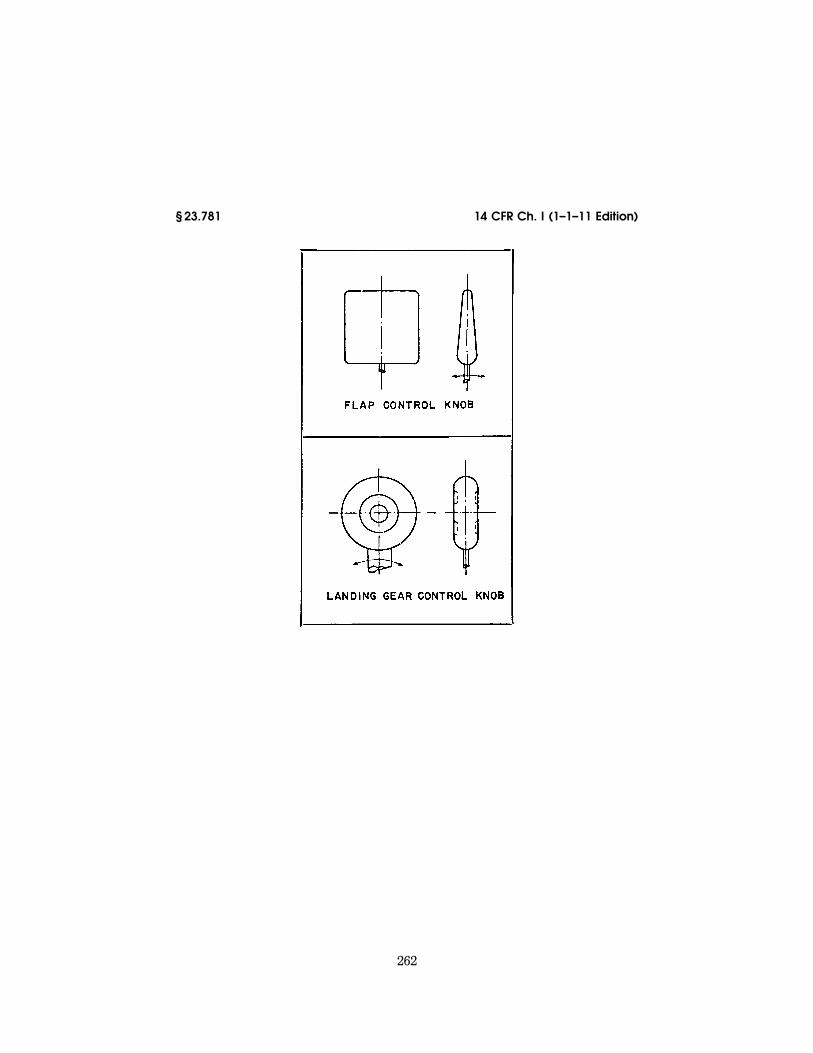
262
14 CFR Ch. I (1–1–11 Edition) § 23.781
VerDate Mar<15>2010 14:10 Mar 01, 2011 Jkt 223043 PO 00000 Frm 00272 Fmt 8010 Sfmt 8006 Y:\SGML\223043.XXX 223043 EC
28S
E91
.016
</G
PH
>
ww
oods
2 on
DS
K1D
XX
6B1P
RO
D w
ith C
FR
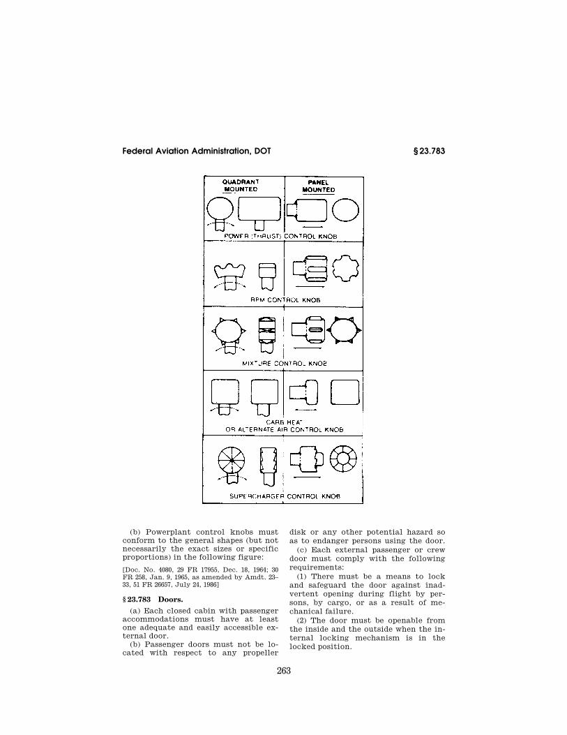
263
Federal Aviation Administration, DOT § 23.783
(b) Powerplant control knobs must conform to the general shapes (but not necessarily the exact sizes or specific proportions) in the following figure:
[Doc. No. 4080, 29 FR 17955, Dec. 18, 1964; 30 FR 258, Jan. 9, 1965, as amended by Amdt. 23– 33, 51 FR 26657, July 24, 1986]
§ 23.783 Doors. (a) Each closed cabin with passenger
accommodations must have at least one adequate and easily accessible ex-ternal door.
(b) Passenger doors must not be lo-cated with respect to any propeller
disk or any other potential hazard so as to endanger persons using the door.
(c) Each external passenger or crew door must comply with the following requirements:
(1) There must be a means to lock and safeguard the door against inad-vertent opening during flight by per-sons, by cargo, or as a result of me-chanical failure.
(2) The door must be openable from the inside and the outside when the in-ternal locking mechanism is in the locked position.
VerDate Mar<15>2010 14:10 Mar 01, 2011 Jkt 223043 PO 00000 Frm 00273 Fmt 8010 Sfmt 8010 Y:\SGML\223043.XXX 223043 EC
28S
E91
.017
</G
PH
>
ww
oods
2 on
DS
K1D
XX
6B1P
RO
D w
ith C
FR

264
14 CFR Ch. I (1–1–11 Edition) § 23.785
(3) There must be a means of opening which is simple and obvious and is ar-ranged and marked inside and outside so that the door can be readily located, unlocked, and opened, even in dark-ness.
(4) The door must meet the marking requirements of § 23.811 of this part.
(5) The door must be reasonably free from jamming as a result of fuselage deformation in an emergency landing.
(6) Auxiliary locking devices that are actuated externally to the airplane may be used but such devices must be overridden by the normal internal opening means.
(d) In addition, each external pas-senger or crew door, for a commuter category airplane, must comply with the following requirements:
(1) Each door must be openable from both the inside and outside, even though persons may be crowded against the door on the inside of the airplane.
(2) If inward opening doors are used, there must be a means to prevent occu-pants from crowding against the door to the extent that would interfere with opening the door.
(3) Auxiliary locking devices may be used.
(e) Each external door on a com-muter category airplane, each external door forward of any engine or propeller on a normal, utility, or acrobatic cat-egory airplane, and each door of the pressure vessel on a pressurized air-plane must comply with the following requirements:
(1) There must be a means to lock and safeguard each external door, in-cluding cargo and service type doors, against inadvertent opening in flight, by persons, by cargo, or as a result of mechanical failure or failure of a single structural element, either during or after closure.
(2) There must be a provision for di-rect visual inspection of the locking mechanism to determine if the exter-nal door, for which the initial opening movement is not inward, is fully closed and locked. The provisions must be dis-cernible, under operating lighting con-ditions, by a crewmember using a flashlight or an equivalent lighting source.
(3) There must be a visual warning means to signal a flight crewmember if the external door is not fully closed and locked. The means must be de-signed so that any failure, or combina-tion of failures, that would result in an erroneous closed and locked indication is improbable for doors for which the initial opening movement is not in-ward.
(f) In addition, for commuter cat-egory airplanes, the following require-ments apply:
(1) Each passenger entry door must qualify as a floor level emergency exit. This exit must have a rectangular opening of not less than 24 inches wide by 48 inches high, with corner radii not greater than one-third the width of the exit.
(2) If an integral stair is installed at a passenger entry door, the stair must be designed so that, when subjected to the inertia loads resulting from the ul-timate static load factors in § 23.561(b)(2) and following the collapse of one or more legs of the landing gear, it will not reduce the effectiveness of emergency egress through the pas-senger entry door.
(g) If lavatory doors are installed, they must be designed to preclude an occupant from becoming trapped inside the lavatory. If a locking mechanism is installed, it must be capable of being unlocked from outside of the lavatory.
[Doc. No. 4080, 29 FR 17955, Dec. 18, 1964; 30 FR 258, Jan. 9, 1965, as amended by Amdt. 23– 36, 53 FR 30813, Aug. 15, 1988; Amdt. 23–46, 59 FR 25772, May 17, 1994; Amdt. 23–49, 61 FR 5166, Feb. 9, 1996]
§ 23.785 Seats, berths, litters, safety belts, and shoulder harnesses.
There must be a seat or berth for each occupant that meets the fol-lowing:
(a) Each seat/restraint system and the supporting structure must be de-signed to support occupants weighing at least 215 pounds when subjected to the maximum load factors cor-responding to the specified flight and ground load conditions, as defined in the approved operating envelope of the airplane. In addition, these loads must be multiplied by a factor of 1.33 in de-termining the strength of all fittings and the attachment of—
VerDate Mar<15>2010 14:10 Mar 01, 2011 Jkt 223043 PO 00000 Frm 00274 Fmt 8010 Sfmt 8010 Y:\SGML\223043.XXX 223043ww
oods
2 on
DS
K1D
XX
6B1P
RO
D w
ith C
FR

265
Federal Aviation Administration, DOT § 23.785
(1) Each seat to the structure; and (2) Each safety belt and shoulder har-
ness to the seat or structure. (b) Each forward-facing or aft-facing
seat/restraint system in normal, util-ity, or acrobatic category airplanes must consist of a seat, a safety belt, and a shoulder harness, with a metal- to-metal latching device, that are de-signed to provide the occupant protec-tion provisions required in § 23.562. Other seat orientations must provide the same level of occupant protection as a forward-facing or aft-facing seat with a safety belt and a shoulder har-ness, and must provide the protection provisions of § 23.562.
(c) For commuter category airplanes, each seat and the supporting structure must be designed for occupants weigh-ing at least 170 pounds when subjected to the inertia loads resulting from the ultimate static load factors prescribed in § 23.561(b)(2) of this part. Each occu-pant must be protected from serious head injury when subjected to the iner-tia loads resulting from these load fac-tors by a safety belt and shoulder har-ness, with a metal-to-metal latching device, for the front seats and a safety belt, or a safety belt and shoulder har-ness, with a metal-to-metal latching device, for each seat other than the front seats.
(d) Each restraint system must have a single-point release for occupant evacuation.
(e) The restraint system for each crewmember must allow the crew-member, when seated with the safety belt and shoulder harness fastened, to perform all functions necessary for flight operations.
(f) Each pilot seat must be designed for the reactions resulting from the ap-plication of pilot forces to the primary flight controls as prescribed in § 23.395 of this part.
(g) There must be a means to secure each safety belt and shoulder harness, when not in use, to prevent inter-ference with the operation of the air-plane and with rapid occupant egress in an emergency.
(h) Unless otherwise placarded, each seat in a utility or acrobatic category airplane must be designed to accommo-date an occupant wearing a parachute.
(i) The cabin area surrounding each seat, including the structure, interior walls, instrument panel, control wheel, pedals, and seats within striking dis-tance of the occupant’s head or torso (with the restraint system fastened) must be free of potentially injurious objects, sharp edges, protuberances, and hard surfaces. If energy absorbing designs or devices are used to meet this requirement, they must protect the oc-cupant from serious injury when the occupant is subjected to the inertia loads resulting from the ultimate stat-ic load factors prescribed in § 23.561(b)(2) of this part, or they must comply with the occupant protection provisions of § 23.562 of this part, as re-quired in paragraphs (b) and (c) of this section.
(j) Each seat track must be fitted with stops to prevent the seat from sliding off the track.
(k) Each seat/restraint system may use design features, such as crushing or separation of certain components, to reduce occupant loads when showing compliance with the requirements of § 23.562 of this part; otherwise, the sys-tem must remain intact.
(l) For the purposes of this section, a front seat is a seat located at a flight crewmember station or any seat lo-cated alongside such a seat.
(m) Each berth, or provisions for a litter, installed parallel to the longitu-dinal axis of the airplane, must be de-signed so that the forward part has a padded end-board, canvas diaphragm, or equivalent means that can with-stand the load reactions from a 215- pound occupant when subjected to the inertia loads resulting from the ulti-mate static load factors of § 23.561(b)(2) of this part. In addition—
(1) Each berth or litter must have an occupant restraint system and may not have corners or other parts likely to cause serious injury to a person occu-pying it during emergency landing con-ditions; and
(2) Occupant restraint system attach-ments for the berth or litter must withstand the inertia loads resulting from the ultimate static load factors of § 23.561(b)(2) of this part.
(n) Proof of compliance with the stat-ic strength requirements of this sec-tion for seats and berths approved as
VerDate Mar<15>2010 14:10 Mar 01, 2011 Jkt 223043 PO 00000 Frm 00275 Fmt 8010 Sfmt 8010 Y:\SGML\223043.XXX 223043ww
oods
2 on
DS
K1D
XX
6B1P
RO
D w
ith C
FR

266
14 CFR Ch. I (1–1–11 Edition) § 23.787
part of the type design and for seat and berth installations may be shown by—
(1) Structural analysis, if the struc-ture conforms to conventional airplane types for which existing methods of analysis are known to be reliable;
(2) A combination of structural anal-ysis and static load tests to limit load; or
(3) Static load tests to ultimate loads.
[Amdt. 23–36, 53 FR 30813, Aug. 15, 1988; Amdt. 23–36, 54 FR 50737, Dec. 11, 1989; Amdt. 23–49, 61 FR 5167, Feb. 9, 1996]
§ 23.787 Baggage and cargo compart-ments.
(a) Each baggage and cargo compart-ment must:
(1) Be designed for its placarded max-imum weight of contents and for the critical load distributions at the appro-priate maximum load factors cor-responding to the flight and ground load conditions of this part.
(2) Have means to prevent the con-tents of any compartment from becom-ing a hazard by shifting, and to protect any controls, wiring, lines, equipment or accessories whose damage or failure would affect safe operations.
(3) Have a means to protect occu-pants from injury by the contents of any compartment, located aft of the occupants and separated by structure, when the ultimate forward inertial load factor is 9g and assuming the max-imum allowed baggage or cargo weight for the compartment.
(b) Designs that provide for baggage or cargo to be carried in the same com-partment as passengers must have a means to protect the occupants from injury when the baggage or cargo is subjected to the inertial loads result-ing from the ultimate static load fac-tors of § 23.561(b)(3), assuming the max-imum allowed baggage or cargo weight for the compartment.
(c) For airplanes that are used only for the carriage of cargo, the flightcrew emergency exits must meet the re-quirements of § 23.807 under any cargo loading conditions.
[Doc. No. 27806, 61 FR 5167, Feb. 9, 1996]
§ 23.791 Passenger information signs. For those airplanes in which the
flightcrew members cannot observe the
other occupants’ seats or where the flightcrew members’ compartment is separated from the passenger compart-ment, there must be at least one illu-minated sign (using either letters or symbols) notifying all passengers when seat belts should be fastened. Signs that notify when seat belts should be fastened must:
(a) When illuminated, be legible to each person seated in the passenger compartment under all probable light-ing conditions; and
(b) Be installed so that a flightcrew member can, when seated at the flightcrew member’s station, turn the illumination on and off.
[Doc. No. 27806, 61 FR 5167, Feb. 9, 1996]
§ 23.803 Emergency evacuation.
(a) For commuter category airplanes, an evacuation demonstration must be conducted utilizing the maximum number of occupants for which certifi-cation is desired. The demonstration must be conducted under simulated night conditions using only the emer-gency exits on the most critical side of the airplane. The participants must be representative of average airline pas-sengers with no prior practice or re-hearsal for the demonstration. Evacu-ation must be completed within 90 sec-onds.
(b) In addition, when certification to the emergency exit provisions of § 23.807(d)(4) is requested, only the emergency lighting system required by § 23.812 may be used to provide cabin in-terior illumination during the evacu-ation demonstration required in para-graph (a) of this section.
[Amdt. 23–34, 52 FR 1831, Jan. 15, 1987, as amended by Amdt. 23–46, 59 FR 25773, May 17, 1994]
§ 23.805 Flightcrew emergency exits.
For airplanes where the proximity of the passenger emergency exits to the flightcrew area does not offer a conven-ient and readily accessible means of evacuation for the flightcrew, the fol-lowing apply:
(a) There must be either one emer-gency exit on each side of the airplane, or a top hatch emergency exit, in the flightcrew area;
VerDate Mar<15>2010 14:10 Mar 01, 2011 Jkt 223043 PO 00000 Frm 00276 Fmt 8010 Sfmt 8010 Y:\SGML\223043.XXX 223043ww
oods
2 on
DS
K1D
XX
6B1P
RO
D w
ith C
FR
267
Federal Aviation Administration, DOT § 23.807
(b) Each emergency exit must be lo-cated to allow rapid evacuation of the crew and have a size and shape of at least a 19- by 20-inch unobstructed rec-tangular opening; and
(c) For each emergency exit that is not less than six feet from the ground, an assisting means must be provided. The assisting means may be a rope or any other means demonstrated to be suitable for the purpose. If the assist-ing means is a rope, or an approved de-vice equivalent to a rope, it must be—
(1) Attached to the fuselage structure at or above the top of the emergency exit opening or, for a device at a pilot’s emergency exit window, at another ap-proved location if the stowed device, or its attachment, would reduce the pi-lot’s view; and
(2) Able (with its attachment) to withstand a 400-pound static load.
[Doc. No. 26324, 59 FR 25773, May 17, 1994]
§ 23.807 Emergency exits. (a) Number and location. Emergency
exits must be located to allow escape without crowding in any probable crash attitude. The airplane must have at least the following emergency exits:
(1) For all airplanes with a seating capacity of two or more, excluding air-planes with canopies, at least one emergency exit on the opposite side of the cabin from the main door specified in § 23.783 of this part.
(2) [Reserved] (3) If the pilot compartment is sepa-
rated from the cabin by a door that is likely to block the pilot’s escape in a minor crash, there must be an exit in the pilot’s compartment. The number of exits required by paragraph (a)(1) of this section must then be separately determined for the passenger compart-ment, using the seating capacity of that compartment.
(4) Emergency exits must not be lo-cated with respect to any propeller disk or any other potential hazard so as to endanger persons using that exit.
(b) Type and operation. Emergency exits must be movable windows, panels, canopies, or external doors, openable from both inside and outside the air-plane, that provide a clear and unob-structed opening large enough to admit a 19-by-26-inch ellipse. Auxiliary lock-ing devices used to secure the airplane
must be designed to be overridden by the normal internal opening means. The inside handles of emergency exits that open outward must be adequately protected against inadvertent oper-ation. In addition, each emergency exit must—
(1) Be readily accessible, requiring no exceptional agility to be used in emer-gencies;
(2) Have a method of opening that is simple and obvious;
(3) Be arranged and marked for easy location and operation, even in dark-ness;
(4) Have reasonable provisions against jamming by fuselage deforma-tion; and
(5) In the case of acrobatic category airplanes, allow each occupant to aban-don the airplane at any speed between VSO and VD; and
(6) In the case of utility category air-planes certificated for spinning, allow each occupant to abandon the airplane at the highest speed likely to be achieved in the maneuver for which the airplane is certificated.
(c) Tests. The proper functioning of each emergency exit must be shown by tests.
(d) Doors and exits. In addition, for commuter category airplanes, the fol-lowing requirements apply:
(1) In addition to the passenger entry door—
(i) For an airplane with a total pas-senger seating capacity of 15 or fewer, an emergency exit, as defined in para-graph (b) of this section, is required on each side of the cabin; and
(ii) For an airplane with a total pas-senger seating capacity of 16 through 19, three emergency exits, as defined in paragraph (b) of this section, are re-quired with one on the same side as the passenger entry door and two on the side opposite the door.
(2) A means must be provided to lock each emergency exit and to safeguard against its opening in flight, either in-advertently by persons or as a result of mechanical failure. In addition, a means for direct visual inspection of the locking mechanism must be pro-vided to determine that each emer-gency exit for which the initial opening movement is outward is fully locked.
VerDate Mar<15>2010 14:10 Mar 01, 2011 Jkt 223043 PO 00000 Frm 00277 Fmt 8010 Sfmt 8010 Y:\SGML\223043.XXX 223043ww
oods
2 on
DS
K1D
XX
6B1P
RO
D w
ith C
FR

268
14 CFR Ch. I (1–1–11 Edition) § 23.811
(3) Each required emergency exit, ex-cept floor level exits, must be located over the wing or, if not less than six feet from the ground, must be provided with an acceptable means to assist the occupants to descend to the ground. Emergency exits must be distributed as uniformly as practical, taking into ac-count passenger seating configuration.
(4) Unless the applicant has complied with paragraph (d)(1) of this section, there must be an emergency exit on the side of the cabin opposite the pas-senger entry door, provided that—
(i) For an airplane having a pas-senger seating configuration of nine or fewer, the emergency exit has a rectan-gular opening measuring not less than 19 inches by 26 inches high with corner radii not greater than one-third the width of the exit, located over the wing, with a step up inside the airplane of not more than 29 inches and a step down outside the airplane of not more than 36 inches;
(ii) For an airplane having a pas-senger seating configuration of 10 to 19 passengers, the emergency exit has a rectangular opening measuring not less than 20 inches wide by 36 inches high, with corner radii not greater than one- third the width of the exit, and with a step up inside the airplane of not more than 20 inches. If the exit is located over the wing, the step down outside the airplane may not exceed 27 inches; and
(iii) The airplane complies with the additional requirements of §§ 23.561(b)(2)(iv), 23.803(b), 23.811(c), 23.812, 23.813(b), and 23.815.
(e) For multiengine airplanes, ditch-ing emergency exits must be provided in accordance with the following re-quirements, unless the emergency exits required by paragraph (a) or (d) of this section already comply with them:
(1) One exit above the waterline on each side of the airplane having the di-mensions specified in paragraph (b) or (d) of this section, as applicable; and
(2) If side exits cannot be above the waterline, there must be a readily ac-cessible overhead hatch emergency exit that has a rectangular opening meas-uring not less than 20 inches wide by 36 inches long, with corner radii not
greater than one-third the width of the exit.
[Doc. No. 4080, 29 FR 17955, Dec. 18, 1964, as amended by Amdt. 23–7, 34 FR 13092, Aug. 13, 1969; Amdt. 23–10, 36 FR 2864, Feb. 11, 1971; Amdt. 23–34, 52 FR 1831, Jan. 15, 1987; Amdt. 23–36, 53 FR 30814, Aug. 15, 1988; 53 FR 34194, Sept. 2, 1988; Amdt. 23–46, 59 FR 25773, May 17, 1994; Amdt. 23–49, 61 FR 5167, Feb. 9, 1996]
§ 23.811 Emergency exit marking. (a) Each emergency exit and external
door in the passenger compartment must be externally marked and readily identifiable from outside the airplane by—
(1) A conspicuous visual identifica-tion scheme; and
(2) A permanent decal or placard on or adjacent to the emergency exit which shows the means of opening the emergency exit, including any special instructions, if applicable.
(b) In addition, for commuter cat-egory airplanes, these exits and doors must be internally marked with the word ‘‘exit’’ by a sign which has white letters 1 inch high on a red background 2 inches high, be self-illuminated or independently, internally electrically illuminated, and have a minimum brightness of at least 160 micro-lamberts. The color may be reversed if the passenger compartment illumina-tion is essentially the same.
(c) In addition, when certification to the emergency exit provisions of § 23.807(d)(4) is requested, the following apply:
(1) Each emergency exit, its means of access, and its means of opening, must be conspicuously marked;
(2) The identity and location of each emergency exit must be recognizable from a distance equal to the width of the cabin;
(3) Means must be provided to assist occupants in locating the emergency exits in conditions of dense smoke;
(4) The location of the operating han-dle and instructions for opening each emergency exit from inside the air-plane must be shown by marking that is readable from a distance of 30 inches;
(5) Each passenger entry door oper-ating handle must—
(i) Be self-illuminated with an initial brightness of at least 160 micro-lamberts; or
VerDate Mar<15>2010 14:10 Mar 01, 2011 Jkt 223043 PO 00000 Frm 00278 Fmt 8010 Sfmt 8010 Y:\SGML\223043.XXX 223043ww
oods
2 on
DS
K1D
XX
6B1P
RO
D w
ith C
FR
269
Federal Aviation Administration, DOT § 23.812
(ii) Be conspicuously located and well illuminated by the emergency lighting even in conditions of occupant crowd-ing at the door;
(6) Each passenger entry door with a locking mechanism that is released by rotary motion of the handle must be marked—
(i) With a red arrow, with a shaft of at least three-fourths of an inch wide and a head twice the width of the shaft, extending along at least 70 degrees of arc at a radius approximately equal to three-fourths of the handle length;
(ii) So that the center line of the exit handle is within ± one inch of the pro-jected point of the arrow when the han-dle has reached full travel and has re-leased the locking mechanism;
(iii) With the word ‘‘open’’ in red let-ters, one inch high, placed horizontally near the head of the arrow; and
(7) In addition to the requirements of paragraph (a) of this section, the exter-nal marking of each emergency exit must—
(i) Include a 2-inch colorband out-lining the exit; and
(ii) Have a color contrast that is readily distinguishable from the sur-rounding fuselage surface. The contrast must be such that if the reflectance of the darker color is 15 percent or less, the reflectance of the lighter color must be at least 45 percent. ‘‘Reflec-tance’’ is the ratio of the luminous flux reflected by a body to the luminous flux it receives. When the reflectance of the darker color is greater than 15 percent, at least a 30 percent difference between its reflectance and the reflec-tance of the lighter color must be pro-vided.
[Amdt. 23–36, 53 FR 30814, Aug. 15, 1988; 53 FR 34194, Sept. 2, 1988, as amended by Amdt. 23– 46, 59 FR 25773, May 17, 1994]
§ 23.812 Emergency lighting.
When certification to the emergency exit provisions of § 23.807(d)(4) is re-quested, the following apply:
(a) An emergency lighting system, independent of the main cabin lighting system, must be installed. However, the source of general cabin illumina-tion may be common to both the emer-gency and main lighting systems if the power supply to the emergency light-
ing system is independent of the power supply to the main lighting system.
(b) There must be a crew warning light that illuminates in the cockpit when power is on in the airplane and the emergency lighting control device is not armed.
(c) The emergency lights must be op-erable manually from the flightcrew station and be provided with automatic activation. The cockpit control device must have ‘‘on,’’ ‘‘off,’’ and ‘‘armed’’ posi-tions so that, when armed in the cock-pit, the lights will operate by auto-matic activation.
(d) There must be a means to safe-guard against inadvertent operation of the cockpit control device from the ‘‘armed’’ or ‘‘on’’ positions.
(e) The cockpit control device must have provisions to allow the emergency lighting system to be armed or acti-vated at any time that it may be need-ed.
(f) When armed, the emergency light-ing system must activate and remain lighted when—
(1) The normal electrical power of the airplane is lost; or
(2) The airplane is subjected to an impact that results in a deceleration in excess of 2g and a velocity change in excess of 3.5 feet-per-second, acting along the longitudinal axis of the air-plane; or
(3) Any other emergency condition exists where automatic activation of the emergency lighting is necessary to aid with occupant evacuation.
(g) The emergency lighting system must be capable of being turned off and reset by the flightcrew after automatic activation.
(h) The emergency lighting system must provide internal lighting, includ-ing—
(1) Illuminated emergency exit mark-ing and locating signs, including those required in § 23.811(b);
(2) Sources of general illumination in the cabin that provide an average illu-mination of not less than 0.05 foot-can-dle and an illumination at any point of not less than 0.01 foot-candle when measured along the center line of the main passenger aisle(s) and at the seat armrest height; and
(3) Floor proximity emergency escape path marking that provides emergency
VerDate Mar<15>2010 14:10 Mar 01, 2011 Jkt 223043 PO 00000 Frm 00279 Fmt 8010 Sfmt 8010 Y:\SGML\223043.XXX 223043ww
oods
2 on
DS
K1D
XX
6B1P
RO
D w
ith C
FR
270
14 CFR Ch. I (1–1–11 Edition) § 23.813
evacuation guidance for the airplane occupants when all sources of illumina-tion more than 4 feet above the cabin aisle floor are totally obscured.
(i) The energy supply to each emer-gency lighting unit must provide the required level of illumination for at least 10 minutes at the critical ambient conditions after activation of the emergency lighting system.
(j) If rechargeable batteries are used as the energy supply for the emergency lighting system, they may be re-charged from the main electrical power system of the airplane provided the charging circuit is designed to preclude inadvertent battery discharge into the charging circuit faults. If the emer-gency lighting system does not include a charging circuit, battery condition monitors are required.
(k) Components of the emergency lighting system, including batteries, wiring, relays, lamps, and switches, must be capable of normal operation after being subjected to the inertia forces resulting from the ultimate load factors prescribed in § 23.561(b)(2).
(l) The emergency lighting system must be designed so that after any sin-gle transverse vertical separation of the fuselage during a crash landing:
(1) At least 75 percent of all elec-trically illuminated emergency lights required by this section remain opera-tive; and
(2) Each electrically illuminated exit sign required by § 23.811 (b) and (c) re-mains operative, except those that are directly damaged by the fuselage sepa-ration.
[Doc. No. 26324, 59 FR 25774, May 17, 1994]
§ 23.813 Emergency exit access. (a) For commuter category airplanes,
access to window-type emergency exits may not be obstructed by seats or seat backs.
(b) In addition, when certification to the emergency exit provisions of § 23.807(d)(4) is requested, the following emergency exit access must be pro-vided:
(1) The passageway leading from the aisle to the passenger entry door must be unobstructed and at least 20 inches wide.
(2) There must be enough space next to the passenger entry door to allow
assistance in evacuation of passengers without reducing the unobstructed width of the passageway below 20 inches.
(3) If it is necessary to pass through a passageway between passenger com-partments to reach a required emer-gency exit from any seat in the pas-senger cabin, the passageway must be unobstructed; however, curtains may be used if they allow free entry through the passageway.
(4) No door may be installed in any partition between passenger compart-ments unless that door has a means to latch it in the open position. The latch-ing means must be able to withstand the loads imposed upon it by the door when the door is subjected to the iner-tia loads resulting from the ultimate static load factors prescribed in § 23.561(b)(2).
(5) If it is necessary to pass through a doorway separating the passenger cabin from other areas to reach a re-quired emergency exit from any pas-senger seat, the door must have a means to latch it in the open position. The latching means must be able to withstand the loads imposed upon it by the door when the door is subjected to the inertia loads resulting from the ul-timate static load factors prescribed in § 23.561(b)(2).
[Amdt. 23–36, 53 FR 30815, Aug. 15, 1988, as amended by Amdt. 23–46, 59 FR 25774, May 17, 1994]
§ 23.815 Width of aisle.
(a) Except as provided in paragraph (b) of this section, for commuter cat-egory airplanes, the width of the main passenger aisle at any point between seats must equal or exceed the values in the following table:
Number of pas-senger seats
Minimum main passenger aisle width
Less than 25 inches from floor
25 inches and more from floor
10 through 19 ....... 9 inches ................ 15 inches.
(b) When certification to the emer-gency exist provisions of § 23.807(d)(4) is requested, the main passenger aisle width at any point between the seats must equal or exceed the following val-ues:
VerDate Mar<15>2010 14:10 Mar 01, 2011 Jkt 223043 PO 00000 Frm 00280 Fmt 8010 Sfmt 8010 Y:\SGML\223043.XXX 223043ww
oods
2 on
DS
K1D
XX
6B1P
RO
D w
ith C
FR

271
Federal Aviation Administration, DOT § 23.843
Number of passenger seats
Minimum main passenger aisle width (inches)
Less than 25 inches from floor
25 inches and more from floor
10 or fewer ................................ 1 12 15 11 through 19 ............................ 12 20
1 A narrower width not less than 9 inches may be approved when substantiated by tests found necessary by the Administrator.
[Amdt. 23–34, 52 FR 1831, Jan. 15, 1987, as amended by Amdt. 23–46, 59 FR 25774, May 17, 1994]
§ 23.831 Ventilation. (a) Each passenger and crew compart-
ment must be suitably ventilated. Car-bon monoxide concentration may not exceed one part in 20,000 parts of air.
(b) For pressurized airplanes, the ventilating air in the flightcrew and passenger compartments must be free of harmful or hazardous concentrations of gases and vapors in normal oper-ations and in the event of reasonably probable failures or malfunctioning of the ventilating, heating, pressuriza-tion, or other systems and equipment. If accumulation of hazardous quan-tities of smoke in the cockpit area is reasonably probable, smoke evacuation must be readily accomplished starting with full pressurization and without depressurizing beyond safe limits.
[Doc. No. 4080, 29 FR 17955, Dec. 18, 1964; 30 FR 258, Jan. 9, 1965, as amended by Amdt. 23– 34, 52 FR 1831, Jan. 15, 1987; Amdt. 23–42, 56 FR 354, Jan. 3, 1991]
PRESSURIZATION
§ 23.841 Pressurized cabins. (a) If certification for operation over
25,000 feet is requested, the airplane must be able to maintain a cabin pres-sure altitude of not more than 15,000 feet in event of any probable failure or malfunction in the pressurization sys-tem.
(b) Pressurized cabins must have at least the following valves, controls, and indicators, for controlling cabin pressure:
(1) Two pressure relief valves to auto-matically limit the positive pressure differential to a predetermined value at the maximum rate of flow delivered by the pressure source. The combined capacity of the relief valves must be
large enough so that the failure of any one valve would not cause an appre-ciable rise in the pressure differential. The pressure differential is positive when the internal pressure is greater than the external.
(2) Two reverse pressure differential relief valves (or their equivalent) to automatically prevent a negative pres-sure differential that would damage the structure. However, one valve is enough if it is of a design that reason-ably precludes its malfunctioning.
(3) A means by which the pressure differential can be rapidly equalized.
(4) An automatic or manual regulator for controlling the intake or exhaust airflow, or both, for maintaining the required internal pressures and airflow rates.
(5) Instruments to indicate to the pilot the pressure differential, the cabin pressure altitude, and the rate of change of cabin pressure altitude.
(6) Warning indication at the pilot station to indicate when the safe or preset pressure differential is exceeded and when a cabin pressure altitude of 10,000 feet is exceeded.
(7) A warning placard for the pilot if the structure is not designed for pres-sure differentials up to the maximum relief valve setting in combination with landing loads.
(8) A means to stop rotation of the compressor or to divert airflow from the cabin if continued rotation of an engine-driven cabin compressor or con-tinued flow of any compressor bleed air will create a hazard if a malfunction occurs.
[Amdt. 23–14, 38 FR 31822, Nov. 19, 1973, as amended by Amdt. 23–17, 41 FR 55464, Dec. 20, 1976; Amdt. 23–49, 61 FR 5167, Feb. 9, 1996]
§ 23.843 Pressurization tests.
(a) Strength test. The complete pres-surized cabin, including doors, win-dows, canopy, and valves, must be test-ed as a pressure vessel for the pressure differential specified in § 23.365(d).
(b) Functional tests. The following functional tests must be performed:
(1) Tests of the functioning and ca-pacity of the positive and negative pressure differential valves, and of the emergency release valve, to simulate the effects of closed regulator valves.
VerDate Mar<15>2010 14:10 Mar 01, 2011 Jkt 223043 PO 00000 Frm 00281 Fmt 8010 Sfmt 8010 Y:\SGML\223043.XXX 223043ww
oods
2 on
DS
K1D
XX
6B1P
RO
D w
ith C
FR

272
14 CFR Ch. I (1–1–11 Edition) § 23.851
(2) Tests of the pressurization system to show proper functioning under each possible condition of pressure, tem-perature, and moisture, up to the max-imum altitude for which certification is requested.
(3) Flight tests, to show the perform-ance of the pressure supply, pressure and flow regulators, indicators, and warning signals, in steady and stepped climbs and descents at rates cor-responding to the maximum attainable within the operating limitations of the airplane, up to the maximum altitude for which certification is requested.
(4) Tests of each door and emergency exit, to show that they operate prop-erly after being subjected to the flight tests prescribed in paragraph (b)(3) of this section.
FIRE PROTECTION
§ 23.851 Fire extinguishers.
(a) There must be at least one hand fire extinguisher for use in the pilot compartment that is located within easy access of the pilot while seated.
(b) There must be at least one hand fire extinguisher located conveniently in the passenger compartment—
(1) Of each airplane accommodating more than 6 passengers; and
(2) Of each commuter category air-plane.
(c) For hand fire extinguishers, the following apply:
(1) The type and quantity of each ex-tinguishing agent used must be appro-priate to the kinds of fire likely to occur where that agent is to be used.
(2) Each extinguisher for use in a per-sonnel compartment must be designed to minimize the hazard of toxic gas concentrations.
[Doc. No. 26269, 58 FR 42165, Aug. 6, 1993]
§ 23.853 Passenger and crew compart-ment interiors.
For each compartment to be used by the crew or passengers:
(a) The materials must be at least flame-resistant;
(b) [Reserved] (c) If smoking is to be prohibited,
there must be a placard so stating, and if smoking is to be allowed—
(1) There must be an adequate num-ber of self-contained, removable ash-trays; and
(2) Where the crew compartment is separated from the passenger compart-ment, there must be at least one illu-minated sign (using either letters or symbols) notifying all passengers when smoking is prohibited. Signs which no-tify when smoking is prohibited must—
(i) When illuminated, be legible to each passenger seated in the passenger cabin under all probable lighting condi-tions; and
(ii) Be so constructed that the crew can turn the illumination on and off; and
(d) In addition, for commuter cat-egory airplanes the following require-ments apply:
(1) Each disposal receptacle for tow-els, paper, or waste must be fully en-closed and constructed of at least fire resistant materials and must contain fires likely to occur in it under normal use. The ability of the disposal recep-tacle to contain those fires under all probable conditions of wear, misalign-ment, and ventilation expected in serv-ice must be demonstrated by test. A placard containing the legible words ‘‘No Cigarette Disposal’’ must be lo-cated on or near each disposal recep-tacle door.
(2) Lavatories must have ‘‘No Smok-ing’’ or ‘‘No Smoking in Lavatory’’ plac-ards located conspicuously on each side of the entry door and self-contained, removable ashtrays located conspicu-ously on or near the entry side of each lavatory door, except that one ashtray may serve more than one lavatory door if it can be seen from the cabin side of each lavatory door served. The plac-ards must have red letters at least 1⁄2 inch high on a white background at least 1 inch high (a ‘‘No Smoking’’ sym-bol may be included on the placard).
(3) Materials (including finishes or decorative surfaces applied to the ma-terials) used in each compartment oc-cupied by the crew or passengers must meet the following test criteria as ap-plicable:
(i) Interior ceiling panels, interior wall panels, partitions, galley struc-ture, large cabinet walls, structural flooring, and materials used in the con-struction of stowage compartments
VerDate Mar<15>2010 14:10 Mar 01, 2011 Jkt 223043 PO 00000 Frm 00282 Fmt 8010 Sfmt 8010 Y:\SGML\223043.XXX 223043ww
oods
2 on
DS
K1D
XX
6B1P
RO
D w
ith C
FR
273
Federal Aviation Administration, DOT § 23.853
(other than underseat stowage com-partments and compartments for stow-ing small items such as magazines and maps) must be self-extinguishing when tested vertically in accordance with the applicable portions of appendix F of this part or by other equivalent methods. The average burn length may not exceed 6 inches and the average flame time after removal of the flame source may not exceed 15 seconds. Drippings from the test specimen may not continue to flame for more than an average of 3 seconds after falling.
(ii) Floor covering, textiles (includ-ing draperies and upholstery), seat cushions, padding, decorative and non-decorative coated fabrics, leather, trays and galley furnishings, electrical conduit, thermal and acoustical insula-tion and insulation covering, air duct-ing, joint and edge covering, cargo compartment liners, insulation blan-kets, cargo covers and transparencies, molded and thermoformed parts, air ducting joints, and trim strips (decora-tive and chafing), that are constructed of materials not covered in paragraph (d)(3)(iv) of this section must be self ex-tinguishing when tested vertically in accordance with the applicable por-tions of appendix F of this part or other approved equivalent methods. The average burn length may not ex-ceed 8 inches and the average flame time after removal of the flame source may not exceed 15 seconds. Drippings from the test specimen may not con-tinue to flame for more than an aver-age of 5 seconds after falling.
(iii) Motion picture film must be safety film meeting the Standard Spec-ifications for Safety Photographic Film PH1.25 (available from the Amer-ican National Standards Institute, 1430 Broadway, New York, N.Y. 10018) or an FAA approved equivalent. If the film travels through ducts, the ducts must meet the requirements of paragraph (d)(3)(ii) of this section.
(iv) Acrylic windows and signs, parts constructed in whole or in part of elas-tomeric materials, edge-lighted instru-ment assemblies consisting of two or more instruments in a common hous-ing, seatbelts, shoulder harnesses, and cargo and baggage tiedown equipment, including containers, bins, pallets, etc., used in passenger or crew compart-
ments, may not have an average burn rate greater than 2.5 inches per minute when tested horizontally in accordance with the applicable portions of appen-dix F of this part or by other approved equivalent methods.
(v) Except for electrical wire cable insulation, and for small parts (such as knobs, handles, rollers, fasteners, clips, grommets, rub strips, pulleys, and small electrical parts) that the Admin-istrator finds would not contribute sig-nificantly to the propagation of a fire, materials in items not specified in paragraphs (d)(3)(i), (ii), (iii), or (iv) of this section may not have a burn rate greater than 4.0 inches per minute when tested horizontally in accordance with the applicable portions of appen-dix F of this part or by other approved equivalent methods.
(e) Lines, tanks, or equipment con-taining fuel, oil, or other flammable fluids may not be installed in such compartments unless adequately shielded, isolated, or otherwise pro-tected so that any breakage or failure of such an item would not create a haz-ard.
(f) Airplane materials located on the cabin side of the firewall must be self- extinguishing or be located at such a distance from the firewall, or otherwise protected, so that ignition will not occur if the firewall is subjected to a flame temperature of not less than 2,000 degrees F for 15 minutes. For self- extinguishing materials (except elec-trical wire and cable insulation and small parts that the Administrator finds would not contribute signifi-cantly to the propagation of a fire), a vertifical self-extinguishing test must be conducted in accordance with appen-dix F of this part or an equivalent method approved by the Adminis-trator. The average burn length of the material may not exceed 6 inches and the average flame time after removal of the flame source may not exceed 15 seconds. Drippings from the material test specimen may not continue to flame for more than an average of 3 seconds after falling.
[Amdt. 23–14, 23 FR 31822, Nov. 19, 1973, as amended by Amdt. 23–23, 43 FR 50593, Oct. 30, 1978; Amdt. 23–25, 45 FR 7755, Feb. 4, 1980; Amdt. 23–34, 52 FR 1831, Jan. 15, 1987]
VerDate Mar<15>2010 14:10 Mar 01, 2011 Jkt 223043 PO 00000 Frm 00283 Fmt 8010 Sfmt 8010 Y:\SGML\223043.XXX 223043ww
oods
2 on
DS
K1D
XX
6B1P
RO
D w
ith C
FR
274
14 CFR Ch. I (1–1–11 Edition) § 23.855
§ 23.855 Cargo and baggage compart-ment fire protection.
(a) Sources of heat within each cargo and baggage compartment that are ca-pable of igniting the compartment con-tents must be shielded and insulated to prevent such ignition.
(b) Each cargo and baggage compart-ment must be constructed of materials that meet the appropriate provisions of § 23.853(d)(3).
(c) In addition, for commuter cat-egory airplanes, each cargo and bag-gage compartment must:
(1) Be located where the presence of a fire would be easily discovered by the pilots when seated at their duty sta-tion, or it must be equipped with a smoke or fire detector system to give a warning at the pilots’ station, and pro-vide sufficient access to enable a pilot to effectively reach any part of the compartment with the contents of a hand held fire extinguisher, or
(2) Be equipped with a smoke or fire detector system to give a warning at the pilots’ station and have ceiling and sidewall liners and floor panels con-structed of materials that have been subjected to and meet the 45 degree angle test of appendix F of this part. The flame may not penetrate (pass through) the material during applica-tion of the flame or subsequent to its removal. The average flame time after removal of the flame source may not exceed 15 seconds, and the average glow time may not exceed 10 seconds. The compartment must be constructed to provide fire protection that is not less than that required of its individual panels; or
(3) Be constructed and sealed to con-tain any fire within the compartment.
[Doc. No. 27806, 61 FR 5167, Feb. 9, 1996]
§ 23.859 Combustion heater fire pro-tection.
(a) Combustion heater fire regions. The following combustion heater fire re-gions must be protected from fire in ac-cordance with the applicable provisions of §§ 23.1182 through 23.1191 and 23.1203:
(1) The region surrounding the heat-er, if this region contains any flam-mable fluid system components (ex-cluding the heater fuel system) that could—
(i) Be damaged by heater malfunc-tioning; or
(ii) Allow flammable fluids or vapors to reach the heater in case of leakage.
(2) The region surrounding the heat-er, if the heater fuel system has fit-tings that, if they leaked, would allow fuel vapor to enter this region.
(3) The part of the ventilating air passage that surrounds the combustion chamber.
(b) Ventilating air ducts. Each ven-tilating air duct passing through any fire region must be fireproof. In addi-tion—
(1) Unless isolation is provided by fireproof valves or by equally effective means, the ventilating air duct down-stream of each heater must be fireproof for a distance great enough to ensure that any fire originating in the heater can be contained in the duct; and
(2) Each part of any ventilating duct passing through any region having a flammable fluid system must be con-structed or isolated from that system so that the malfunctioning of any com-ponent of that system cannot intro-duce flammable fluids or vapors into the ventilating airstream.
(c) Combustion air ducts. Each com-bustion air duct must be fireproof for a distance great enough to prevent dam-age from backfiring or reverse flame propagation. In addition—
(1) No combustion air duct may have a common opening with the ventilating airstream unless flames from backfires or reverse burning cannot enter the ventilating airstream under any oper-ating condition, including reverse flow or malfunctioning of the heater or its associated components; and
(2) No combustion air duct may re-strict the prompt relief of any backfire that, if so restricted, could cause heat-er failure.
(d) Heater controls: general. Provision must be made to prevent the hazardous accumulation of water or ice on or in any heater control component, control system tubing, or safety control.
(e) Heater safety controls. (1) Each combustion heater must have the fol-lowing safety controls:
(i) Means independent of the compo-nents for the normal continuous con-trol of air temperature, airflow, and
VerDate Mar<15>2010 14:10 Mar 01, 2011 Jkt 223043 PO 00000 Frm 00284 Fmt 8010 Sfmt 8010 Y:\SGML\223043.XXX 223043ww
oods
2 on
DS
K1D
XX
6B1P
RO
D w
ith C
FR

275
Federal Aviation Administration, DOT § 23.863
fuel flow must be provided to auto-matically shut off the ignition and fuel supply to that heater at a point remote from that heater when any of the fol-lowing occurs:
(A) The heater exchanger tempera-ture exceeds safe limits.
(B) The ventilating air temperature exceeds safe limits.
(C) The combustion airflow becomes inadequate for safe operation.
(D) The ventilating airflow becomes inadequate for safe operation.
(ii) Means to warn the crew when any heater whose heat output is essential for safe operation has been shut off by the automatic means prescribed in paragraph (e)(1)(i) of this section.
(2) The means for complying with paragraph (e)(1)(i) of this section for any individual heater must—
(i) Be independent of components serving any other heater whose heat output is essential for safe operations; and
(ii) Keep the heater off until re-started by the crew.
(f) Air intakes. Each combustion and ventilating air intake must be located so that no flammable fluids or vapors can enter the heater system under any operating condition—
(1) During normal operation; or (2) As a result of the malfunctioning
of any other component. (g) Heater exhaust. Heater exhaust
systems must meet the provisions of §§ 23.1121 and 23.1123. In addition, there must be provisions in the design of the heater exhaust system to safely expel the products of combustion to prevent the occurrence of—
(1) Fuel leakage from the exhaust to surrounding compartments;
(2) Exhaust gas impingement on sur-rounding equipment or structure;
(3) Ignition of flammable fluids by the exhaust, if the exhaust is in a com-partment containing flammable fluid lines; and
(4) Restrictions in the exhaust sys-tem to relieve backfires that, if so re-stricted, could cause heater failure.
(h) Heater fuel systems. Each heater fuel system must meet each power-plant fuel system requirement affect-ing safe heater operation. Each heater fuel system component within the ven-tilating airstream must be protected
by shrouds so that no leakage from those components can enter the ven-tilating airstream.
(i) Drains. There must be means to safely drain fuel that might accumu-late within the combustion chamber or the heater exchanger. In addition—
(1) Each part of any drain that oper-ates at high temperatures must be pro-tected in the same manner as heater exhausts; and
(2) Each drain must be protected from hazardous ice accumulation under any operating condition.
[Amdt. 23–27, 45 FR 70387, Oct. 23, 1980]
§ 23.863 Flammable fluid fire protec-tion.
(a) In each area where flammable fluids or vapors might escape by leak-age of a fluid system, there must be means to minimize the probability of ignition of the fluids and vapors, and the resultant hazard if ignition does occur.
(b) Compliance with paragraph (a) of this section must be shown by analysis or tests, and the following factors must be considered:
(1) Possible sources and paths of fluid leakage, and means of detecting leak-age.
(2) Flammability characteristics of fluids, including effects of any combus-tible or absorbing materials.
(3) Possible ignition sources, includ-ing electrical faults, overheating of equipment, and malfunctioning of pro-tective devices.
(4) Means available for controlling or extinguishing a fire, such as stopping flow of fluids, shutting down equip-ment, fireproof containment, or use of extinguishing agents.
(5) Ability of airplane components that are critical to safety of flight to withstand fire and heat.
(c) If action by the flight crew is re-quired to prevent or counteract a fluid fire (e.g. equipment shutdown or actu-ation of a fire extinguisher), quick act-ing means must be provided to alert the crew.
(d) Each area where flammable fluids or vapors might escape by leakage of a fluid system must be identified and de-fined.
[Amdt. 23–23, 43 FR 50593, Oct. 30, 1978]
VerDate Mar<15>2010 14:10 Mar 01, 2011 Jkt 223043 PO 00000 Frm 00285 Fmt 8010 Sfmt 8010 Y:\SGML\223043.XXX 223043ww
oods
2 on
DS
K1D
XX
6B1P
RO
D w
ith C
FR

276
14 CFR Ch. I (1–1–11 Edition) § 23.865
§ 23.865 Fire protection of flight con-trols, engine mounts, and other flight structure.
Flight controls, engine mounts, and other flight structure located in des-ignated fire zones, or in adjacent areas that would be subjected to the effects of fire in the designated fire zones, must be constructed of fireproof mate-rial or be shielded so that they are ca-pable of withstanding the effects of a fire. Engine vibration isolators must incorporate suitable features to ensure that the engine is retained if the non- fireproof portions of the isolators dete-riorate from the effects of a fire.
[Doc. No. 27805, 61 FR 5148, Feb. 9, 1996]
ELECTRICAL BONDING AND LIGHTNING PROTECTION
§ 23.867 Electrical bonding and protec-tion against lightning and static electricity.
(a) The airplane must be protected against catastrophic effects from light-ning.
(b) For metallic components, compli-ance with paragraph (a) of this section may be shown by—
(1) Bonding the components properly to the airframe; or
(2) Designing the components so that a strike will not endanger the airplane.
(c) For nonmetallic components, compliance with paragraph (a) of this section may be shown by—
(1) Designing the components to min-imize the effect of a strike; or
(2) Incorporating acceptable means of diverting the resulting electrical cur-rent so as not to endanger the airplane.
[Amdt. 23–7, 34 FR 13092, Aug. 13, 1969]
MISCELLANEOUS
§ 23.871 Leveling means.
There must be means for determining when the airplane is in a level position on the ground.
[Amdt. 23–7, 34 FR 13092, Aug. 13, 1969]
Subpart E—Powerplant GENERAL
§ 23.901 Installation. (a) For the purpose of this part, the
airplane powerplant installation in-cludes each component that—
(1) Is necessary for propulsion; and (2) Affects the safety of the major
propulsive units. (b) Each powerplant installation
must be constructed and arranged to— (1) Ensure safe operation to the max-
imum altitude for which approval is re-quested.
(2) Be accessible for necessary inspec-tions and maintenance.
(c) Engine cowls and nacelles must be easily removable or openable by the pilot to provide adequate access to and exposure of the engine compartment for preflight checks.
(d) Each turbine engine installation must be constructed and arranged to—
(1) Result in carcass vibration char-acteristics that do not exceed those es-tablished during the type certification of the engine.
(2) Ensure that the capability of the installed engine to withstand the in-gestion of rain, hail, ice, and birds into the engine inlet is not less than the ca-pability established for the engine itself under § 23.903(a)(2).
(e) The installation must comply with—
(1) The instructions provided under the engine type certificate and the pro-peller type certificate.
(2) The applicable provisions of this subpart.
(f) Each auxiliary power unit instal-lation must meet the applicable por-tions of this part.
[Doc. No. 4080, 29 FR 17955, Dec. 18, 1964, as amended by Amdt. 23–7, 34 FR 13092, Aug. 13, 1969; Amdt. 23–18, 42 FR 15041, Mar. 17, 1977; Amdt. 23–29, 49 FR 6846, Feb. 23, 1984; Amdt. 23–34, 52 FR 1832, Jan. 15, 1987; Amdt. 23–34, 52 FR 34745, Sept. 14, 1987; Amdt. 23–43, 58 FR 18970, Apr. 9, 1993; Amdt. 23–51, 61 FR 5136, Feb. 9, 1996; Amdt. 23–53, 63 FR 14797, Mar. 26, 1998]
§ 23.903 Engines. (a) Engine type certificate. (1) Each en-
gine must have a type certificate and must meet the applicable requirements of part 34 of this chapter.
VerDate Mar<15>2010 14:10 Mar 01, 2011 Jkt 223043 PO 00000 Frm 00286 Fmt 8010 Sfmt 8010 Y:\SGML\223043.XXX 223043ww
oods
2 on
DS
K1D
XX
6B1P
RO
D w
ith C
FR
277
Federal Aviation Administration, DOT § 23.903
(2) Each turbine engine and its in-stallation must comply with one of the following:
(i) Sections 33.76, 33.77 and 33.78 of this chapter in effect on December 13, 2000, or as subsequently amended; or
(ii) Sections 33.77 and 33.78 of this chapter in effect on April 30, 1998, or as subsequently amended before Decem-ber 13, 2000; or
(iii) Section 33.77 of this chapter in effect on October 31, 1974, or as subse-quently amended before April 30, 1998, unless that engine’s foreign object in-gestion service history has resulted in an unsafe condition; or
(iv) Be shown to have a foreign object ingestion service history in similar in-stallation locations which has not re-sulted in any unsafe condition.
NOTE: § 33.77 of this chapter in effect on Oc-tober 31, 1974, was published in 14 CFR parts 1 to 59, Revised as of January 1, 1975. See 39 FR 35467, October 1, 1974.
(b) Turbine engine installations. For turbine engine installations—
(1) Design precautions must be taken to minimize the hazards to the airplane in the event of an engine rotor failure or of a fire originating inside the en-gine which burns through the engine case.
(2) The powerplant systems associ-ated with engine control devices, sys-tems, and instrumentation must be de-signed to give reasonable assurance that those operating limitations that adversely affect turbine rotor struc-tural integrity will not be exceeded in service.
(c) Engine isolation. The powerplants must be arranged and isolated from each other to allow operation, in at least one configuration, so that the failure or malfunction of any engine, or the failure or malfunction (including destruction by fire in the engine com-partment) of any system that can af-fect an engine (other than a fuel tank if only one fuel tank is installed), will not:
(1) Prevent the continued safe oper-ation of the remaining engines; or
(2) Require immediate action by any crewmember for continued safe oper-ation of the remaining engines.
(d) Starting and stopping (piston en-gine). (1) The design of the installation must be such that risk of fire or me-
chanical damage to the engine or air-plane, as a result of starting the engine in any conditions in which starting is to be permitted, is reduced to a min-imum. Any techniques and associated limitations for engine starting must be established and included in the Air-plane Flight Manual, approved manual material, or applicable operating plac-ards. Means must be provided for—
(i) Restarting any engine of a multi-engine airplane in flight, and
(ii) Stopping any engine in flight, after engine failure, if continued en-gine rotation would cause a hazard to the airplane.
(2) In addition, for commuter cat-egory airplanes, the following apply:
(i) Each component of the stopping system on the engine side of the fire-wall that might be exposed to fire must be at least fire resistant.
(ii) If hydraulic propeller feathering systems are used for this purpose, the feathering lines must be at least fire resistant under the operating condi-tions that may be expected to exist during feathering.
(e) Starting and stopping (turbine en-gine). Turbine engine installations must comply with the following:
(1) The design of the installation must be such that risk of fire or me-chanical damage to the engine or the airplane, as a result of starting the en-gine in any conditions in which start-ing is to be permitted, is reduced to a minimum. Any techniques and associ-ated limitations must be established and included in the Airplane Flight Manual, approved manual material, or applicable operating placards.
(2) There must be means for stopping combustion within any engine and for stopping the rotation of any engine if continued rotation would cause a haz-ard to the airplane. Each component of the engine stopping system located in any fire zone must be fire resistant. If hydraulic propeller feathering systems are used for stopping the engine, the hydraulic feathering lines or hoses must be fire resistant.
(3) It must be possible to restart an engine in flight. Any techniques and associated limitations must be estab-lished and included in the Airplane Flight Manual, approved manual mate-rial, or applicable operating placards.
VerDate Mar<15>2010 14:10 Mar 01, 2011 Jkt 223043 PO 00000 Frm 00287 Fmt 8010 Sfmt 8010 Y:\SGML\223043.XXX 223043ww
oods
2 on
DS
K1D
XX
6B1P
RO
D w
ith C
FR

278
14 CFR Ch. I (1–1–11 Edition) § 23.904
(4) It must be demonstrated in flight that when restarting engines following a false start, all fuel or vapor is dis-charged in such a way that it does not constitute a fire hazard.
(f) Restart envelope. An altitude and airspeed envelope must be established for the airplane for in-flight engine re-starting and each installed engine must have a restart capability within that envelope.
(g) Restart capability. For turbine en-gine powered airplanes, if the min-imum windmilling speed of the en-gines, following the in-flight shutdown of all engines, is insufficient to provide the necessary electrical power for en-gine ignition, a power source inde-pendent of the engine-driven electrical power generating system must be pro-vided to permit in-flight engine igni-tion for restarting.
[Amdt. 23–14, 38 FR 31822, Nov. 19, 1973]
EDITORIAL NOTE: For FEDERAL REGISTER ci-tations affecting § 23.903, see the List of CFR Sections Affected, which appears in the Finding Aids section of the printed volume and at www.fdsys.gov.
§ 23.904 Automatic power reserve sys-tem.
If installed, an automatic power re-serve (APR) system that automatically advances the power or thrust on the op-erating engine(s), when any engine fails during takeoff, must comply with appendix H of this part.
[Doc. No. 26344, 58 FR 18970, Apr. 9, 1993]
§ 23.905 Propellers. (a) Each propeller must have a type
certificate. (b) Engine power and propeller shaft
rotational speed may not exceed the limits for which the propeller is certifi-cated.
(c) Each featherable propeller must have a means to unfeather it in flight.
(d) The propeller blade pitch control system must meet the requirements of §§ 35.21, 35.23, 35.42 and 35.43 of this chapter.
(e) All areas of the airplane forward of the pusher propeller that are likely to accumulate and shed ice into the propeller disc during any operating condition must be suitably protected to prevent ice formation, or it must be
shown that any ice shed into the pro-peller disc will not create a hazardous condition.
(f) Each pusher propeller must be marked so that the disc is conspicuous under normal daylight ground condi-tions.
(g) If the engine exhaust gases are discharged into the pusher propeller disc, it must be shown by tests, or analysis supported by tests, that the propeller is capable of continuous safe operation.
(h) All engine cowling, access doors, and other removable items must be de-signed to ensure that they will not sep-arate from the airplane and contact the pusher propeller.
[Doc. No. 4080, 29 FR 17955, Dec. 18, 1964, as amended by Amdt. 23–26, 45 FR 60171, Sept. 11, 1980; Amdt. 23–29, 49 FR 6847, Feb. 23, 1984; Amdt. 23–43, 58 FR 18970, Apr. 9, 1993; Amdt. No. 23–59, 73 FR 63345, Oct. 24, 2008]
§ 23.907 Propeller vibration and fa-tigue.
This section does not apply to fixed- pitch wood propellers of conventional design.
(a) The applicant must determine the magnitude of the propeller vibration stresses or loads, including any stress peaks and resonant conditions, throughout the operational envelope of the airplane by either:
(1) Measurement of stresses or loads through direct testing or analysis based on direct testing of the propeller on the airplane and engine installation for which approval is sought; or
(2) Comparison of the propeller to similar propellers installed on similar airplane installations for which these measurements have been made.
(b) The applicant must demonstrate by tests, analysis based on tests, or previous experience on similar designs that the propeller does not experience harmful effects of flutter throughout the operational envelope of the air-plane.
(c) The applicant must perform an evaluation of the propeller to show that failure due to fatigue will be avoided throughout the operational life of the propeller using the fatigue and structural data obtained in accordance with part 35 of this chapter and the vi-bration data obtained from compliance
VerDate Mar<15>2010 14:10 Mar 01, 2011 Jkt 223043 PO 00000 Frm 00288 Fmt 8010 Sfmt 8010 Y:\SGML\223043.XXX 223043ww
oods
2 on
DS
K1D
XX
6B1P
RO
D w
ith C
FR
279
Federal Aviation Administration, DOT § 23.925
with paragraph (a) of this section. For the purpose of this paragraph, the pro-peller includes the hub, blades, blade retention component and any other propeller component whose failure due to fatigue could be catastrophic to the airplane. This evaluation must include:
(1) The intended loading spectra in-cluding all reasonably foreseeable pro-peller vibration and cyclic load pat-terns, identified emergency conditions, allowable overspeeds and overtorques, and the effects of temperatures and hu-midity expected in service.
(2) The effects of airplane and pro-peller operating and airworthiness lim-itations.
[Amdt. No. 23–59, 73 FR 63345, Oct. 24, 2008]
§ 23.909 Turbocharger systems. (a) Each turbocharger must be ap-
proved under the engine type certifi-cate or it must be shown that the tur-bocharger system, while in its normal engine installation and operating in the engine environment—
(1) Can withstand, without defect, an endurance test of 150 hours that meets the applicable requirements of § 33.49 of this subchapter; and
(2) Will have no adverse effect upon the engine.
(b) Control system malfunctions, vi-brations, and abnormal speeds and temperatures expected in service may not damage the turbocharger com-pressor or turbine.
(c) Each turbocharger case must be able to contain fragments of a com-pressor or turbine that fails at the highest speed that is obtainable with normal speed control devices inoper-ative.
(d) Each intercooler installation, where provided, must comply with the following—
(1) The mounting provisions of the intercooler must be designed to with-stand the loads imposed on the system;
(2) It must be shown that, under the installed vibration environment, the intercooler will not fail in a manner al-lowing portions of the intercooler to be ingested by the engine; and
(3) Airflow through the intercooler must not discharge directly on any air-plane component (e.g., windshield) un-less such discharge is shown to cause
no hazard to the airplane under all op-erating conditions.
(e) Engine power, cooling character-istics, operating limits, and procedures affected by the turbocharger system in-stallations must be evaluated. Turbo-charger operating procedures and limi-tations must be included in the Air-plane Flight Manual in accordance with § 23.1581.
[Amdt. 23–7, 34 FR 13092, Aug. 13, 1969, as amended by Amdt. 23–43, 58 FR 18970, Apr. 9, 1993]
§ 23.925 Propeller clearance. Unless smaller clearances are sub-
stantiated, propeller clearances, with the airplane at the most adverse com-bination of weight and center of grav-ity, and with the propeller in the most adverse pitch position, may not be less than the following:
(a) Ground clearance. There must be a clearance of at least seven inches (for each airplane with nose wheel landing gear) or nine inches (for each airplane with tail wheel landing gear) between each propeller and the ground with the landing gear statically deflected and in the level, normal takeoff, or taxing at-titude, whichever is most critical. In addition, for each airplane with con-ventional landing gear struts using fluid or mechanical means for absorb-ing landing shocks, there must be posi-tive clearance between the propeller and the ground in the level takeoff at-titude with the critical tire completely deflated and the corresponding landing gear strut bottomed. Positive clear-ance for airplanes using leaf spring struts is shown with a deflection cor-responding to 1.5g.
(b) Aft-mounted propellers. In addition to the clearances specified in para-graph (a) of this section, an airplane with an aft mounted propeller must be designed such that the propeller will not contact the runway surface when the airplane is in the maximum pitch attitude attainable during normal takeoffs and landings.
(c) Water clearance. There must be a clearance of at least 18 inches between each propeller and the water, unless compliance with § 23.239 can be shown with a lesser clearance.
(d) Structural clearance. There must be—
VerDate Mar<15>2010 14:10 Mar 01, 2011 Jkt 223043 PO 00000 Frm 00289 Fmt 8010 Sfmt 8010 Y:\SGML\223043.XXX 223043ww
oods
2 on
DS
K1D
XX
6B1P
RO
D w
ith C
FR

280
14 CFR Ch. I (1–1–11 Edition) § 23.929
(1) At least one inch radial clearance between the blade tips and the airplane structure, plus any additional radial clearance necessary to prevent harmful vibration;
(2) At least one-half inch longitudinal clearance between the propeller blades or cuffs and stationary parts of the air-plane; and
(3) Positive clearance between other rotating parts of the propeller or spin-ner and stationary parts of the air-plane.
[Doc. No. 4080, 29 FR 17955, Dec. 18, 1964, as amended by Amdt. 23–43, 58 FR 18971, Apr. 9, 1993; Amdt. 23–51, 61 FR 5136, Feb. 9, 1996; Amdt. 23–48, 61 FR 5148, Feb. 9, 1996]
§ 23.929 Engine installation ice protec-tion.
Propellers (except wooden propellers) and other components of complete en-gine installations must be protected against the accumulation of ice as nec-essary to enable satisfactory func-tioning without appreciable loss of thrust when operated in the icing con-ditions for which certification is re-quested.
[Amdt. 23–14, 33 FR 31822, Nov. 19, 1973, as amended by Amdt. 23–51, 61 FR 5136, Feb. 9, 1996]
§ 23.933 Reversing systems. (a) For turbojet and turbofan reversing
systems. (1) Each system intended for ground operation only must be de-signed so that, during any reversal in flight, the engine will produce no more than flight idle thrust. In addition, it must be shown by analysis or test, or both, that—
(i) Each operable reverser can be re-stored to the forward thrust position; or
(ii) The airplane is capable of contin-ued safe flight and landing under any possible position of the thrust reverser.
(2) Each system intended for in-flight use must be designed so that no unsafe condition will result during normal op-eration of the system, or from any fail-ure, or likely combination of failures, of the reversing system under any op-erating condition including ground op-eration. Failure of structural elements need not be considered if the prob-ability of this type of failure is ex-tremely remote.
(3) Each system must have a means to prevent the engine from producing more than idle thrust when the revers-ing system malfunctions; except that it may produce any greater thrust that is shown to allow directional control to be maintained, with aerodynamic means alone, under the most critical reversing condition expected in oper-ation.
(b) For propeller reversing systems. (1) Each system must be designed so that no single failure, likely combination of failures or malfunction of the system will result in unwanted reverse thrust under any operating condition. Failure of structural elements need not be con-sidered if the probability of this type of failure is extremely remote.
(2) Compliance with paragraph (b)(1) of this section must be shown by fail-ure analysis, or testing, or both, for propeller systems that allow the pro-peller blades to move from the flight low-pitch position to a position that is substantially less than the normal flight, low-pitch position. The analysis may include or be supported by the analysis made to show compliance with § 35.21 for the type certification of the propeller and associated installation components. Credit will be given for pertinent analysis and testing com-pleted by the engine and propeller manufacturers.
[Doc. No. 26344, 58 FR 18971, Apr. 9, 1993, as amended by Amdt. 23–51, 61 FR 5136, Feb. 9, 1996]
§ 23.934 Turbojet and turbofan engine thrust reverser systems tests.
Thrust reverser systems of turbojet or turbofan engines must meet the re-quirements of § 33.97 of this chapter or it must be demonstrated by tests that engine operation and vibratory levels are not affected.
[Doc. No. 26344, 58 FR 18971, Apr. 9, 1993]
§ 23.937 Turbopropeller-drag limiting systems.
(a) Turbopropeller-powered airplane propeller-drag limiting systems must be designed so that no single failure or malfunction of any of the systems dur-ing normal or emergency operation re-sults in propeller drag in excess of that for which the airplane was designed under the structural requirements of
VerDate Mar<15>2010 14:10 Mar 01, 2011 Jkt 223043 PO 00000 Frm 00290 Fmt 8010 Sfmt 8010 Y:\SGML\223043.XXX 223043ww
oods
2 on
DS
K1D
XX
6B1P
RO
D w
ith C
FR

281
Federal Aviation Administration, DOT § 23.953
this part. Failure of structural ele-ments of the drag limiting systems need not be considered if the prob-ability of this kind of failure is ex-tremely remote.
(b) As used in this section, drag lim-iting systems include manual or auto-matic devices that, when actuated after engine power loss, can move the propeller blades toward the feather po-sition to reduce windmilling drag to a safe level.
[Amdt. 23–7, 34 FR 13093, Aug. 13, 1969, as amended by Amdt. 23–43, 58 FR 18971, Apr. 9, 1993]
§ 23.939 Powerplant operating charac-teristics.
(a) Turbine engine powerplant oper-ating characteristics must be inves-tigated in flight to determine that no adverse characteristics (such as stall, surge, or flameout) are present, to a hazardous degree, during normal and emergency operation within the range of operating limitations of the airplane and of the engine.
(b) Turbocharged reciprocating en-gine operating characteristics must be investigated in flight to assure that no adverse characteristics, as a result of an inadvertent overboost, surge, flood-ing, or vapor lock, are present during normal or emergency operation of the engine(s) throughout the range of oper-ating limitations of both airplane and engine.
(c) For turbine engines, the air inlet system must not, as a result of airflow distortion during normal operation, cause vibration harmful to the engine.
[Amdt. 23–7, 34 FR 13093 Aug. 13, 1969, as amended by Amdt. 23–14, 38 FR 31823, Nov. 19, 1973; Amdt. 23–18, 42 FR 15041, Mar. 17, 1977; Amdt. 23–42, 56 FR 354, Jan. 3, 1991]
§ 23.943 Negative acceleration.
No hazardous malfunction of an en-gine, an auxiliary power unit approved for use in flight, or any component or system associated with the powerplant or auxiliary power unit may occur when the airplane is operated at the negative accelerations within the flight envelopes prescribed in § 23.333. This must be shown for the greatest
value and duration of the acceleration expected in service.
[Amdt. 23–18, 42 FR 15041, Mar. 17, 1977, as amended by Amdt. 23–43, 58 FR 18971, Apr. 9, 1993]
FUEL SYSTEM
§ 23.951 General. (a) Each fuel system must be con-
structed and arranged to ensure fuel flow at a rate and pressure established for proper engine and auxiliary power unit functioning under each likely op-erating condition, including any ma-neuver for which certification is re-quested and during which the engine or auxiliary power unit is permitted to be in operation.
(b) Each fuel system must be ar-ranged so that—
(1) No fuel pump can draw fuel from more than one tank at a time; or
(2) There are means to prevent intro-ducing air into the system.
(c) Each fuel system for a turbine en-gine must be capable of sustained oper-ation throughout its flow and pressure range with fuel initially saturated with water at 80 °F and having 0.75cc of free water per gallon added and cooled to the most critical condition for icing likely to be encountered in operation.
(d) Each fuel system for a turbine en-gine powered airplane must meet the applicable fuel venting requirements of part 34 of this chapter.
[Amdt. 23–15, 39 FR 35459, Oct. 1, 1974, as amended by Amdt. 23–40, 55 FR 32861, Aug. 10, 1990; Amdt. 23–43, 58 FR 18971, Apr. 9, 1993]
§ 23.953 Fuel system independence. (a) Each fuel system for a multien-
gine airplane must be arranged so that, in at least one system configuration, the failure of any one component (other than a fuel tank) will not result in the loss of power of more than one engine or require immediate action by the pilot to prevent the loss of power of more than one engine.
(b) If a single fuel tank (or series of fuel tanks interconnected to function as a single fuel tank) is used on a mul-tiengine airplane, the following must be provided:
(1) Independent tank outlets for each engine, each incorporating a shut-off valve at the tank. This shutoff valve
VerDate Mar<15>2010 14:10 Mar 01, 2011 Jkt 223043 PO 00000 Frm 00291 Fmt 8010 Sfmt 8010 Y:\SGML\223043.XXX 223043ww
oods
2 on
DS
K1D
XX
6B1P
RO
D w
ith C
FR

282
14 CFR Ch. I (1–1–11 Edition) § 23.954
may also serve as the fire wall shutoff valve required if the line between the valve and the engine compartment does not contain more than one quart of fuel (or any greater amount shown to be safe) that can escape into the engine compartment.
(2) At least two vents arranged to minimize the probability of both vents becoming obstructed simultaneously.
(3) Filler caps designed to minimize the probability of incorrect installa-tion or inflight loss.
(4) A fuel system in which those parts of the system from each tank outlet to any engine are independent of each part of the system supplying fuel to any other engine.
[Doc. No. 4080, 29 FR 17955, Dec. 18, 1964, as amended by Amdt. 23–7, 34 FR 13093 Aug. 13, 1969; Amdt. 23–43, 58 FR 18971, Apr. 9, 1993]
§ 23.954 Fuel system lightning protec-tion.
The fuel system must be designed and arranged to prevent the ignition of fuel vapor within the system by—
(a) Direct lightning strikes to areas having a high probability of stroke at-tachment;
(b) Swept lightning strokes on areas where swept strokes are highly prob-able; and
(c) Corona or streamering at fuel vent outlets.
[Amdt. 23–7, 34 FR 13093, Aug. 13, 1969]
§ 23.955 Fuel flow. (a) General. The ability of the fuel
system to provide fuel at the rates specified in this section and at a pres-sure sufficient for proper engine oper-ation must be shown in the attitude that is most critical with respect to fuel feed and quantity of unusable fuel. These conditions may be simulated in a suitable mockup. In addition—
(1) The quantity of fuel in the tank may not exceed the amount established as the unusable fuel supply for that tank under § 23.959(a) plus that quan-tity necessary to show compliance with this section.
(2) If there is a fuel flowmeter, it must be blocked during the flow test and the fuel must flow through the meter or its bypass.
(3) If there is a flowmeter without a bypass, it must not have any probable
failure mode that would restrict fuel flow below the level required for this fuel demonstration.
(4) The fuel flow must include that flow necessary for vapor return flow, jet pump drive flow, and for all other purposes for which fuel is used.
(b) Gravity systems. The fuel flow rate for gravity systems (main and reserve supply) must be 150 percent of the takeoff fuel consumption of the engine.
(c) Pump systems. The fuel flow rate for each pump system (main and re-serve supply) for each reciprocating en-gine must be 125 percent of the fuel flow required by the engine at the max-imum takeoff power approved under this part.
(1) This flow rate is required for each main pump and each emergency pump, and must be available when the pump is operating as it would during takeoff;
(2) For each hand-operated pump, this rate must occur at not more than 60 complete cycles (120 single strokes) per minute.
(3) The fuel pressure, with main and emergency pumps operating simulta-neously, must not exceed the fuel inlet pressure limits of the engine unless it can be shown that no adverse effect oc-curs.
(d) Auxiliary fuel systems and fuel transfer systems. Paragraphs (b), (c), and (f) of this section apply to each auxil-iary and transfer system, except that—
(1) The required fuel flow rate must be established upon the basis of max-imum continuous power and engine ro-tational speed, instead of takeoff power and fuel consumption; and
(2) If there is a placard providing op-erating instructions, a lesser flow rate may be used for transferring fuel from any auxiliary tank into a larger main tank. This lesser flow rate must be ade-quate to maintain engine maximum continuous power but the flow rate must not overfill the main tank at lower engine powers.
(e) Multiple fuel tanks. For recipro-cating engines that are supplied with fuel from more than one tank, if engine power loss becomes apparent due to fuel depletion from the tank selected, it must be possible after switching to any full tank, in level flight, to obtain 75 percent maximum continuous power on that engine in not more than—
VerDate Mar<15>2010 14:10 Mar 01, 2011 Jkt 223043 PO 00000 Frm 00292 Fmt 8010 Sfmt 8010 Y:\SGML\223043.XXX 223043ww
oods
2 on
DS
K1D
XX
6B1P
RO
D w
ith C
FR
283
Federal Aviation Administration, DOT § 23.963
(1) 10 seconds for naturally aspirated single-engine airplanes;
(2) 20 seconds for turbocharged sin-gle-engine airplanes, provided that 75 percent maximum continuous natu-rally aspirated power is regained with-in 10 seconds; or
(3) 20 seconds for multiengine air-planes.
(f) Turbine engine fuel systems. Each turbine engine fuel system must pro-vide at least 100 percent of the fuel flow required by the engine under each in-tended operation condition and maneu-ver. The conditions may be simulated in a suitable mockup. This flow must—
(1) Be shown with the airplane in the most adverse fuel feed condition (with respect to altitudes, attitudes, and other conditions) that is expected in operation; and
(2) For multiengine airplanes, not-withstanding the lower flow rate al-lowed by paragraph (d) of this section, be automatically uninterrupted with respect to any engine until all the fuel scheduled for use by that engine has been consumed. In addition—
(i) For the purposes of this section, ‘‘fuel scheduled for use by that engine’’ means all fuel in any tank intended for use by a specific engine.
(ii) The fuel system design must clearly indicate the engine for which fuel in any tank is scheduled.
(iii) Compliance with this paragraph must require no pilot action after com-pletion of the engine starting phase of operations.
(3) For single-engine airplanes, re-quire no pilot action after completion of the engine starting phase of oper-ations unless means are provided that unmistakenly alert the pilot to take any needed action at least five minutes prior to the needed action; such pilot action must not cause any change in engine operation; and such pilot action must not distract pilot attention from essential flight duties during any phase of operations for which the airplane is approved.
[Doc. No. 4080, 29 FR 17955, Dec. 18, 1964, as amended by Amdt. 23–7, 34 FR 13093, Aug. 13, 1969; Amdt. 23–43, 58 FR 18971, Apr. 9, 1993; Amdt. 23–51, 61 FR 5136, Feb. 9, 1996]
§ 23.957 Flow between interconnected tanks.
(a) It must be impossible, in a grav-ity feed system with interconnected tank outlets, for enough fuel to flow between the tanks to cause an overflow of fuel from any tank vent under the conditions in § 23.959, except that full tanks must be used.
(b) If fuel can be pumped from one tank to another in flight, the fuel tank vents and the fuel transfer system must be designed so that no structural damage to any airplane component can occur because of overfilling of any tank.
[Doc. No. 4080, 29 FR 17955, Dec. 18, 1964, as amended by Amdt. 23–43, 58 FR 18972, Apr. 9, 1993]
§ 23.959 Unusable fuel supply.
(a) The unusable fuel supply for each tank must be established as not less than that quantity at which the first evidence of malfunctioning occurs under the most adverse fuel feed condi-tion occurring under each intended op-eration and flight maneuver involving that tank. Fuel system component fail-ures need not be considered.
(b) The effect on the usable fuel quantity as a result of a failure of any pump shall be determined.
[Amdt. 23–7, 34 FR 13093, Aug. 13, 1969, as amended by Amdt. 23–18, 42 FR 15041, Mar. 17, 1977; Amdt. 23–51, 61 FR 5136, Feb. 9, 1996]
§ 23.961 Fuel system hot weather oper-ation.
Each fuel system must be free from vapor lock when using fuel at its crit-ical temperature, with respect to vapor formation, when operating the airplane in all critical operating and environ-mental conditions for which approval is requested. For turbine fuel, the ini-tial temperature must be 110 °F, ¥0°, +5 °F or the maximum outside air tem-perature for which approval is re-quested, whichever is more critical.
[Doc. No. 26344, 58 FR 18972, Apr. 9, 1993; 58 FR 27060, May 6, 1993]
§ 23.963 Fuel tanks: General.
(a) Each fuel tank must be able to withstand, without failure, the vibra-tion, inertia, fluid, and structural loads
VerDate Mar<15>2010 14:10 Mar 01, 2011 Jkt 223043 PO 00000 Frm 00293 Fmt 8010 Sfmt 8010 Y:\SGML\223043.XXX 223043ww
oods
2 on
DS
K1D
XX
6B1P
RO
D w
ith C
FR
284
14 CFR Ch. I (1–1–11 Edition) § 23.965
that it may be subjected to in oper-ation.
(b) Each flexible fuel tank liner must be shown to be suitable for the par-ticular application.
(c) Each integral fuel tank must have adequate facilities for interior inspec-tion and repair.
(d) The total usable capacity of the fuel tanks must be enough for at least one-half hour of operation at maximum continuous power.
(e) Each fuel quantity indicator must be adjusted, as specified in § 23.1337(b), to account for the unusable fuel supply determined under § 23.959(a).
[Doc. No. 4080, 29 FR 17955, Dec. 18, 1964; 30 FR 258, Jan. 9, 1965, as amended by Amdt 23– 34, 52 FR 1832, Jan. 15, 1987; Amdt. 23–43, 58 FR 18972, Apr. 9, 1993; Amdt. 23–51, 61 FR 5136, Feb. 9, 1996]
§ 23.965 Fuel tank tests. (a) Each fuel tank must be able to
withstand the following pressures with-out failure or leakage:
(1) For each conventional metal tank and nonmetallic tank with walls not supported by the airplane structure, a pressure of 3.5 p.s.i., or that pressure developed during maximum ultimate acceleration with a full tank, which-ever is greater.
(2) For each integral tank, the pres-sure developed during the maximum limit acceleration of the airplane with a full tank, with simultaneous applica-tion of the critical limit structural loads.
(3) For each nonmetallic tank with walls supported by the airplane struc-ture and constructed in an acceptable manner using acceptable basic tank material, and with actual or simulated support conditions, a pressure of 2 p.s.i. for the first tank of a specific design. The supporting structure must be de-signed for the critical loads occurring in the flight or landing strength condi-tions combined with the fuel pressure loads resulting from the corresponding accelerations.
(b) Each fuel tank with large, unsup-ported, or unstiffened flat sur-faces,whose failure or deformation could cause fuel leakage, must be able to withstand the following test without leakage, failure, or excessive deforma-tion of the tank walls:
(1) Each complete tank assembly and its support must be vibration tested while mounted to simulate the actual installation.
(2) Except as specified in paragraph (b)(4) of this section, the tank assembly must be vibrated for 25 hours at a total displacement of not less than 1⁄32 of an inch (unless another displacement is substantiated) while 2⁄3 filled with water or other suitable test fluid.
(3) The test frequency of vibration must be as follows:
(i) If no frequency of vibration result-ing from any rpm within the normal operating range of engine or propeller speeds is critical, the test frequency of vibration is:
(A) The number of cycles per minute obtained by multiplying the maximum continuous propeller speed in rpm by 0.9 for propeller-driven airplanes, and
(B) For non-propeller driven air-planes the test frequency of vibration is 2,000 cycles per minute.
(ii) If only one frequency of vibration resulting from any rpm within the nor-mal operating range of engine or pro-peller speeds is critical, that frequency of vibration must be the test fre-quency.
(iii) If more than one frequency of vi-bration resulting from any rpm within the normal operating range of engine or propeller speeds is critical, the most critical of these frequencies must be the test frequency.
(4) Under paragraph (b)(3) (ii) and (iii) of this section, the time of test must be adjusted to accomplish the same num-ber of vibration cycles that would be accomplished in 25 hours at the fre-quency specified in paragraph (b)(3)(i) of this section.
(5) During the test, the tank assem-bly must be rocked at a rate of 16 to 20 complete cycles per minute, through an angle of 15° on either side of the hor-izontal (30° total), about an axis par-allel to the axis of the fuselage, for 25 hours.
(c) Each integral tank using methods of construction and sealing not pre-viously proven to be adequate by test data or service experience must be able to withstand the vibration test speci-fied in paragraphs (b)(1) through (4) of this section.
VerDate Mar<15>2010 14:10 Mar 01, 2011 Jkt 223043 PO 00000 Frm 00294 Fmt 8010 Sfmt 8010 Y:\SGML\223043.XXX 223043ww
oods
2 on
DS
K1D
XX
6B1P
RO
D w
ith C
FR

285
Federal Aviation Administration, DOT § 23.969
(d) Each tank with a nonmetallic liner must be subjected to the sloshing test outlined in paragraph (b)(5) of this section, with the fuel at room tempera-ture. In addition, a specimen liner of the same basic construction as that to be used in the airplane must, when in-stalled in a suitable test tank, with-stand the sloshing test with fuel at a temperature of 110 °F.
[Doc. No. 4080, 29 FR 17955, Dec. 18, 1964, as amended by Amdt. 23–43, 58 FR 18972, Apr. 9, 1993; Amdt. 23–43, 61 FR 253, Jan. 4, 1996; Amdt. 23–51, 61 FR 5136, Feb. 9, 1996]
§ 23.967 Fuel tank installation. (a) Each fuel tank must be supported
so that tank loads are not con-centrated. In addition—
(1) There must be pads, if necessary, to prevent chafing between each tank and its supports;
(2) Padding must be nonabsorbent or treated to prevent the absorption of fuel;
(3) If a flexible tank liner is used, it must be supported so that it is not re-quired to withstand fluid loads;
(4) Interior surfaces adjacent to the liner must be smooth and free from projections that could cause wear, un-less—
(i) Provisions are made for protection of the liner at those points; or
(ii) The construction of the liner itself provides such protection; and
(5) A positive pressure must be main-tained within the vapor space of each bladder cell under any condition of op-eration, except for a particular condi-tion for which it is shown that a zero or negative pressure will not cause the bladder cell to collapse; and
(6) Syphoning of fuel (other than minor spillage) or collapse of bladder fuel cells may not result from improper securing or loss of the fuel filler cap.
(b) Each tank compartment must be ventilated and drained to prevent the accumulation of flammable fluids or vapors. Each compartment adjacent to a tank that is an integral part of the airplane structure must also be venti-lated and drained.
(c) No fuel tank may be on the engine side of the firewall. There must be at least one-half inch of clearance be-tween the fuel tank and the firewall. No part of the engine nacelle skin that
lies immediately behind a major air opening from the engine compartment may act as the wall of an integral tank.
(d) Each fuel tank must be isolated from personnel compartments by a fume-proof and fuel-proof enclosure that is vented and drained to the exte-rior of the airplane. The required en-closure must sustain any personnel compartment pressurization loads without permanent deformation or fail-ure under the conditions of §§ 23.365 and 23.843 of this part. A bladder-type fuel cell, if used, must have a retaining shell at least equivalent to a metal fuel tank in structural integrity.
(e) Fuel tanks must be designed, lo-cated, and installed so as to retain fuel:
(1) When subjected to the inertia loads resulting from the ultimate stat-ic load factors prescribed in § 23.561(b)(2) of this part; and
(2) Under conditions likely to occur when the airplane lands on a paved runway at a normal landing speed under each of the following conditions:
(i) The airplane in a normal landing attitude and its landing gear retracted.
(ii) The most critical landing gear leg collapsed and the other landing gear legs extended.
In showing compliance with paragraph (e)(2) of this section, the tearing away of an engine mount must be considered unless all the engines are installed above the wing or on the tail or fuse-lage of the airplane.
[Doc. No. 4080, 29 FR 17955, Dec. 18, 1964, as amended by Amdt. 23–7, 34 FR 13903, Aug. 13, 1969; Amdt. 23–14, 38 FR 31823, Nov. 19, 1973; Amdt. 23–18, 42 FR 15041, Mar. 17, 1977; Amdt. 23–26, 45 FR 60171, Sept. 11, 1980; Amdt. 23–36, 53 FR 30815, Aug. 15, 1988; Amdt. 23–43, 58 FR 18972, Apr. 9, 1993]
§ 23.969 Fuel tank expansion space.
Each fuel tank must have an expan-sion space of not less than two percent of the tank capacity, unless the tank vent discharges clear of the airplane (in which case no expansion space is re-quired). It must be impossible to fill the expansion space inadvertently with the airplane in the normal ground atti-tude.
VerDate Mar<15>2010 14:10 Mar 01, 2011 Jkt 223043 PO 00000 Frm 00295 Fmt 8010 Sfmt 8010 Y:\SGML\223043.XXX 223043ww
oods
2 on
DS
K1D
XX
6B1P
RO
D w
ith C
FR
286
14 CFR Ch. I (1–1–11 Edition) § 23.971
§ 23.971 Fuel tank sump.
(a) Each fuel tank must have a drain-able sump with an effective capacity, in the normal ground and flight atti-tudes, of 0.25 percent of the tank capac-ity, or 1⁄16 gallon, whichever is greater.
(b) Each fuel tank must allow drain-age of any hazardous quantity of water from any part of the tank to its sump with the airplane in the normal ground attitude.
(c) Each reciprocating engine fuel system must have a sediment bowl or chamber that is accessible for drain-age; has a capacity of 1 ounce for every 20 gallons of fuel tank capacity; and each fuel tank outlet is located so that, in the normal flight attitude, water will drain from all parts of the tank ex-cept the sump to the sediment bowl or chamber.
(d) Each sump, sediment bowl, and sediment chamber drain required by paragraphs (a), (b), and (c) of this sec-tion must comply with the drain provi-sions of § 23.999(b)(1) and (b)(2).
[Doc. No. 26344, 58 FR 18972, Apr. 9, 1993; 58 FR 27060, May 6, 1993]
§ 23.973 Fuel tank filler connection.
(a) Each fuel tank filler connection must be marked as prescribed in § 23.1557(c).
(b) Spilled fuel must be prevented from entering the fuel tank compart-ment or any part of the airplane other than the tank itself.
(c) Each filler cap must provide a fuel-tight seal for the main filler open-ing. However, there may be small open-ings in the fuel tank cap for venting purposes or for the purpose of allowing passage of a fuel gauge through the cap provided such openings comply with the requirements of § 23.975(a).
(d) Each fuel filling point, except pressure fueling connection points, must have a provision for electrically bonding the airplane to ground fueling equipment.
(e) For airplanes with engines requir-ing gasoline as the only permissible fuel, the inside diameter of the fuel filler opening must be no larger than 2.36 inches.
(f) For airplanes with turbine en-gines, the inside diameter of the fuel
filler opening must be no smaller than 2.95 inches.
[Doc. No. 4080, 29 FR 17955, Dec. 18, 1964; 30 FR 258, Jan. 9, 1965, as amended by Amdt. 23– 18, 42 FR 15041, Mar. 17, 1977; Amdt. 23–43, 58 FR 18972, Apr. 9, 1993; Amdt. 23–51, 61 FR 5136, Feb. 9, 1996]
§ 23.975 Fuel tank vents and carbu-retor vapor vents.
(a) Each fuel tank must be vented from the top part of the expansion space. In addition—
(1) Each vent outlet must be located and constructed in a manner that mini-mizes the possibility of its being ob-structed by ice or other foreign matter;
(2) Each vent must be constructed to prevent siphoning of fuel during nor-mal operation;
(3) The venting capacity must allow the rapid relief of excessive differences of pressure between the interior and exterior of the tank;
(4) Airspaces of tanks with inter-connected outlets must be inter-connected;
(5) There may be no point in any vent line where moisture can accumulate with the airplane in either the ground or level flight attitudes, unless drain-age is provided. Any drain valve in-stalled must be accessible for drainage;
(6) No vent may terminate at a point where the discharge of fuel from the vent outlet will constitute a fire haz-ard or from which fumes may enter personnel compartments; and
(7) Vents must be arranged to pre-vent the loss of fuel, except fuel dis-charged because of thermal expansion, when the airplane is parked in any di-rection on a ramp having a one-percent slope.
(b) Each carburetor with vapor elimi-nation connections and each fuel injec-tion engine employing vapor return provisions must have a separate vent line to lead vapors back to the top of one of the fuel tanks. If there is more than one tank and it is necessary to use these tanks in a definite sequence for any reason, the vapor vent line must lead back to the fuel tank to be used first, unless the relative capac-ities of the tanks are such that return to another tank is preferable.
(c) For acrobatic category airplanes, excessive loss of fuel during acrobatic
VerDate Mar<15>2010 14:10 Mar 01, 2011 Jkt 223043 PO 00000 Frm 00296 Fmt 8010 Sfmt 8010 Y:\SGML\223043.XXX 223043ww
oods
2 on
DS
K1D
XX
6B1P
RO
D w
ith C
FR

287
Federal Aviation Administration, DOT § 23.991
maneuvers, including short periods of inverted flight, must be prevented. It must be impossible for fuel to siphon from the vent when normal flight has been resumed after any acrobatic ma-neuver for which certification is re-quested.
[Doc. No. 4080, 29 FR 17955, Dec. 18, 1964; 30 FR 258, Jan. 9, 1965, as amended by Amdt. 23– 18, 42 FR 15041, Mar. 17, 1977; Amdt. 23–29, 49 FR 6847, Feb. 23, 1984; Amdt. 23–43, 58 FR 18973, Apr. 9, 1993; Amdt. 23–51, 61 FR 5136, Feb. 9, 1996]
§ 23.977 Fuel tank outlet.
(a) There must be a fuel strainer for the fuel tank outlet or for the booster pump. This strainer must—
(1) For reciprocating engine powered airplanes, have 8 to 16 meshes per inch; and
(2) For turbine engine powered air-planes, prevent the passage of any ob-ject that could restrict fuel flow or damage any fuel system component.
(b) The clear area of each fuel tank outlet strainer must be at least five times the area of the outlet line.
(c) The diameter of each strainer must be at least that of the fuel tank outlet.
(d) Each strainer must be accessible for inspection and cleaning.
[Amdt. 23–17, 41 FR 55465, Dec. 20, 1976, as amended by Amdt. 23–43, 58 FR 18973, Apr. 9, 1993]
§ 23.979 Pressure fueling systems.
For pressure fueling systems, the fol-lowing apply:
(a) Each pressure fueling system fuel manifold connection must have means to prevent the escape of hazardous quantities of fuel from the system if the fuel entry valve fails.
(b) An automatic shutoff means must be provided to prevent the quantity of fuel in each tank from exceeding the maximum quantity approved for that tank. This means must—
(1) Allow checking for proper shutoff operation before each fueling of the tank; and
(2) For commuter category airplanes, indicate at each fueling station, a fail-ure of the shutoff means to stop the fuel flow at the maximum quantity ap-proved for that tank.
(c) A means must be provided to pre-vent damage to the fuel system in the event of failure of the automatic shut-off means prescribed in paragraph (b) of this section.
(d) All parts of the fuel system up to the tank which are subjected to fueling pressures must have a proof pressure of 1.33 times, and an ultimate pressure of at least 2.0 times, the surge pressure likely to occur during fueling.
[Amdt. 23–14, 38 FR 31823, Nov. 19, 1973, as amended by Amdt. 23–51, 61 FR 5137, Feb. 9, 1996]
FUEL SYSTEM COMPONENTS
§ 23.991 Fuel pumps.
(a) Main pumps. For main pumps, the following apply:
(1) For reciprocating engine installa-tions having fuel pumps to supply fuel to the engine, at least one pump for each engine must be directly driven by the engine and must meet § 23.955. This pump is a main pump.
(2) For turbine engine installations, each fuel pump required for proper en-gine operation, or required to meet the fuel system requirements of this sub-part (other than those in paragraph (b) of this section), is a main pump. In ad-dition—
(i) There must be at least one main pump for each turbine engine;
(ii) The power supply for the main pump for each engine must be inde-pendent of the power supply for each main pump for any other engine; and
(iii) For each main pump, provision must be made to allow the bypass of each positive displacement fuel pump other than a fuel injection pump ap-proved as part of the engine.
(b) Emergency pumps. There must be an emergency pump immediately avail-able to supply fuel to the engine if any main pump (other than a fuel injection pump approved as part of an engine) fails. The power supply for each emer-gency pump must be independent of the power supply for each corresponding main pump.
(c) Warning means. If both the main pump and emergency pump operate continuously, there must be a means to indicate to the appropriate flight crew-members a malfunction of either pump.
VerDate Mar<15>2010 14:10 Mar 01, 2011 Jkt 223043 PO 00000 Frm 00297 Fmt 8010 Sfmt 8010 Y:\SGML\223043.XXX 223043ww
oods
2 on
DS
K1D
XX
6B1P
RO
D w
ith C
FR

288
14 CFR Ch. I (1–1–11 Edition) § 23.993
(d) Operation of any fuel pump may not affect engine operation so as to create a hazard, regardless of the en-gine power or thrust setting or the functional status of any other fuel pump.
[Doc. No. 4080, 29 FR 17955, Dec. 18, 1964, as amended by Amdt. 23–7, 34 FR 13093, Aug. 13, 1969; Amdt. 23–26, 45 FR 60171, Sept. 11, 1980; Amdt. 23–43, 58 FR 18973, Apr. 9, 1993]
§ 23.993 Fuel system lines and fittings.
(a) Each fuel line must be installed and supported to prevent excessive vi-bration and to withstand loads due to fuel pressure and accelerated flight conditions.
(b) Each fuel line connected to com-ponents of the airplane between which relative motion could exist must have provisions for flexibility.
(c) Each flexible connection in fuel lines that may be under pressure and subjected to axial loading must use flexible hose assemblies.
(d) Each flexible hose must be shown to be suitable for the particular appli-cation.
(e) No flexible hose that might be ad-versely affected by exposure to high temperatures may be used where exces-sive temperatures will exist during op-eration or after engine shutdown.
[Doc. No. 4080, 29 FR 17955, Dec. 18, 1964, as amended by Amdt. 23–43, 58 FR 18973, Apr. 9, 1993]
§ 23.994 Fuel system components.
Fuel system components in an engine nacelle or in the fuselage must be pro-tected from damage which could result in spillage of enough fuel to constitute a fire hazard as a result of a wheels-up landing on a paved runway.
[Amdt. 23–29, 49 FR 6847, Feb. 23, 1984]
§ 23.995 Fuel valves and controls.
(a) There must be a means to allow appropriate flight crew members to rapidly shut off, in flight, the fuel to each engine individually.
(b) No shutoff valve may be on the engine side of any firewall. In addition, there must be means to—
(1) Guard against inadvertent oper-ation of each shutoff valve; and
(2) Allow appropriate flight crew members to reopen each valve rapidly after it has been closed.
(c) Each valve and fuel system con-trol must be supported so that loads re-sulting from its operation or from ac-celerated flight conditions are not transmitted to the lines connected to the valve.
(d) Each valve and fuel system con-trol must be installed so that gravity and vibration will not affect the se-lected position.
(e) Each fuel valve handle and its connections to the valve mechanism must have design features that mini-mize the possibility of incorrect instal-lation.
(f) Each check valve must be con-structed, or otherwise incorporate pro-visions, to preclude incorrect assembly or connection of the valve.
(g) Fuel tank selector valves must— (1) Require a separate and distinct
action to place the selector in the ‘‘OFF’’ position; and
(2) Have the tank selector positions located in such a manner that it is im-possible for the selector to pass through the ‘‘OFF’’ position when changing from one tank to another.
[Doc. No. 4080, 29 FR 17955, Dec. 18, 1964, as amended by Amdt. 23–14, 38 FR 31823, Nov. 19, 1973; Amdt. 23–17, 41 FR 55465, Dec. 20, 1976; Amdt. 23–18, 42 FR 15041, Mar. 17, 1977; Amdt. 23–29, 49 FR 6847, Feb. 23, 1984]
§ 23.997 Fuel strainer or filter. There must be a fuel strainer or filter
between the fuel tank outlet and the inlet of either the fuel metering device or an engine driven positive displace-ment pump, whichever is nearer the fuel tank outlet. This fuel strainer or filter must—
(a) Be accessible for draining and cleaning and must incorporate a screen or element which is easily removable;
(b) Have a sediment trap and drain except that it need not have a drain if the strainer or filter is easily remov-able for drain purposes;
(c) Be mounted so that its weight is not supported by the connecting lines or by the inlet or outlet connections of the strainer or filter itself, unless ade-quate strength margins under all load-ing conditions are provided in the lines and connections; and
VerDate Mar<15>2010 14:10 Mar 01, 2011 Jkt 223043 PO 00000 Frm 00298 Fmt 8010 Sfmt 8010 Y:\SGML\223043.XXX 223043ww
oods
2 on
DS
K1D
XX
6B1P
RO
D w
ith C
FR

289
Federal Aviation Administration, DOT § 23.1001
(d) Have the capacity (with respect to operating limitations established for the engine) to ensure that engine fuel system functioning is not impaired, with the fuel contaminated to a degree (with respect to particle size and den-sity) that is greater than that estab-lished for the engine during its type certification.
(e) In addition, for commuter cat-egory airplanes, unless means are pro-vided in the fuel system to prevent the accumulation of ice on the filter, a means must be provided to automati-cally maintain the fuel flow if ice clog-ging of the filter occurs.
[Amdt. 23–15, 39 FR 35459, Oct. 1, 1974, as amended by Amdt. 23–29, 49 FR 6847, Feb. 23, 1984; Amdt. 23–34, 52 FR 1832, Jan. 15, 1987; Amdt. 23–43, 58 FR 18973, Apr. 9, 1993]
§ 23.999 Fuel system drains. (a) There must be at least one drain
to allow safe drainage of the entire fuel system with the airplane in its normal ground attitude.
(b) Each drain required by paragraph (a) of this section and § 23.971 must—
(1) Discharge clear of all parts of the airplane;
(2) Have a drain valve— (i) That has manual or automatic
means for positive locking in the closed position;
(ii) That is readily accessible; (iii) That can be easily opened and
closed; (iv) That allows the fuel to be caught
for examination; (v) That can be observed for proper
closing; and (vi) That is either located or pro-
tected to prevent fuel spillage in the event of a landing with landing gear re-tracted.
[Doc. No. 4080, 29 FR 17955, Dec. 18, 1964, as amended by Amdt. 23–17, 41 FR 55465, Dec. 20, 1976; Amdt. 23–43, 58 FR 18973, Apr. 9, 1993]
§ 23.1001 Fuel jettisoning system. (a) If the design landing weight is
less than that permitted under the re-quirements of § 23.473(b), the airplane must have a fuel jettisoning system in-stalled that is able to jettison enough fuel to bring the maximum weight down to the design landing weight. The average rate of fuel jettisoning must be at least 1 percent of the maximum
weight per minute, except that the time required to jettison the fuel need not be less than 10 minutes.
(b) Fuel jettisoning must be dem-onstrated at maximum weight with flaps and landing gear up and in—
(1) A power-off glide at 1.4 VS1; (2) A climb, at the speed at which the
one-engine-inoperative enroute climb data have been established in accord-ance with § 23.69(b), with the critical engine inoperative and the remaining engines at maximum continuous power; and
(3) Level flight at 1.4 VS1, if the re-sults of the tests in the conditions specified in paragraphs (b)(1) and (2) of this section show that this condition could be critical.
(c) During the flight tests prescribed in paragraph (b) of this section, it must be shown that—
(1) The fuel jettisoning system and its operation are free from fire hazard;
(2) The fuel discharges clear of any part of the airplane;
(3) Fuel or fumes do not enter any parts of the airplane; and
(4) The jettisoning operation does not adversely affect the controllability of the airplane.
(d) For reciprocating engine powered airplanes, the jettisoning system must be designed so that it is not possible to jettison the fuel in the tanks used for takeoff and landing below the level al-lowing 45 minutes flight at 75 percent maximum continuous power. However, if there is an auxiliary control inde-pendent of the main jettisoning con-trol, the system may be designed to jettison all the fuel.
(e) For turbine engine powered air-planes, the jettisoning system must be designed so that it is not possible to jettison fuel in the tanks used for take-off and landing below the level allow-ing climb from sea level to 10,000 feet and thereafter allowing 45 minutes cruise at a speed for maximum range.
(f) The fuel jettisoning valve must be designed to allow flight crewmembers to close the valve during any part of the jettisoning operation.
(g) Unless it is shown that using any means (including flaps, slots, and slats) for changing the airflow across or around the wings does not adversely af-fect fuel jettisoning, there must be a
VerDate Mar<15>2010 14:10 Mar 01, 2011 Jkt 223043 PO 00000 Frm 00299 Fmt 8010 Sfmt 8010 Y:\SGML\223043.XXX 223043ww
oods
2 on
DS
K1D
XX
6B1P
RO
D w
ith C
FR

290
14 CFR Ch. I (1–1–11 Edition) § 23.1011
placard, adjacent to the jettisoning control, to warn flight crewmembers against jettisoning fuel while the means that change the airflow are being used.
(h) The fuel jettisoning system must be designed so that any reasonably probable single malfunction in the sys-tem will not result in a hazardous con-dition due to unsymmetrical jetti-soning of, or inability to jettison, fuel.
[Amdt. 23–7, 34 FR 13094, Aug. 13, 1969, as amended by Amdt. 23–43, 58 FR 18973, Apr. 9, 1993; Amdt. 23–51, 61 FR 5137, Feb. 9, 1996]
OIL SYSTEM
§ 23.1011 General.
(a) For oil systems and components that have been approved under the en-gine airworthiness requirements and where those requirements are equal to or more severe than the corresponding requirements of subpart E of this part, that approval need not be duplicated. Where the requirements of subpart E of this part are more severe, substan-tiation must be shown to the require-ments of subpart E of this part.
(b) Each engine must have an inde-pendent oil system that can supply it with an appropriate quantity of oil at a temperature not above that safe for continuous operation.
(c) The usable oil tank capacity may not be less than the product of the en-durance of the airplane under critical operating conditions and the maximum oil consumption of the engine under the same conditions, plus a suitable margin to ensure adequate circulation and cooling.
(d) For an oil system without an oil transfer system, only the usable oil tank capacity may be considered. The amount of oil in the engine oil lines, the oil radiator, and the feathering re-serve, may not be considered.
(e) If an oil transfer system is used, and the transfer pump can pump some of the oil in the transfer lines into the main engine oil tanks, the amount of oil in these lines that can be pumped by the transfer pump may be included in the oil capacity.
[Doc. No. 4080, 29 FR 17955, Dec. 18, 1964, as amended by Amdt. 23–43, 58 FR 18973, Apr. 9, 1993]
§ 23.1013 Oil tanks. (a) Installation. Each oil tank must be
installed to— (1) Meet the requirements of § 23.967
(a) and (b); and (2) Withstand any vibration, inertia,
and fluid loads expected in operation. (b) Expansion space. Oil tank expan-
sion space must be provided so that— (1) Each oil tank used with a recipro-
cating engine has an expansion space of not less than the greater of 10 percent of the tank capacity or 0.5 gallon, and each oil tank used with a turbine en-gine has an expansion space of not less than 10 percent of the tank capacity; and
(2) It is impossible to fill the expan-sion space inadvertently with the air-plane in the normal ground attitude.
(c) Filler connection. Each oil tank filler connection must be marked as specified in § 23.1557(c). Each recessed oil tank filler connection of an oil tank used with a turbine engine, that can re-tain any appreciable quantity of oil, must have provisions for fitting a drain.
(d) Vent. Oil tanks must be vented as follows:
(1) Each oil tank must be vented to the engine from the top part of the ex-pansion space so that the vent connec-tion is not covered by oil under any normal flight condition.
(2) Oil tank vents must be arranged so that condensed water vapor that might freeze and obstruct the line can-not accumulate at any point.
(3) For acrobatic category airplanes, there must be means to prevent haz-ardous loss of oil during acrobatic ma-neuvers, including short periods of in-verted flight.
(e) Outlet. No oil tank outlet may be enclosed by any screen or guard that would reduce the flow of oil below a safe value at any operating tempera-ture. No oil tank outlet diameter may be less than the diameter of the engine oil pump inlet. Each oil tank used with a turbine engine must have means to prevent entrance into the tank itself, or into the tank outlet, of any object that might obstruct the flow of oil through the system. There must be a shutoff valve at the outlet of each oil tank used with a turbine engine, unless the external portion of the oil system
VerDate Mar<15>2010 14:10 Mar 01, 2011 Jkt 223043 PO 00000 Frm 00300 Fmt 8010 Sfmt 8010 Y:\SGML\223043.XXX 223043ww
oods
2 on
DS
K1D
XX
6B1P
RO
D w
ith C
FR
291
Federal Aviation Administration, DOT § 23.1019
(including oil tank supports) is fire-proof.
(f) Flexible liners. Each flexible oil tank liner must be of an acceptable kind.
(g) Each oil tank filler cap of an oil tank that is used with an engine must provide an oiltight seal.
[Doc. No. 4080, 29 FR 17955, Dec. 18, 1964, as amended by Amdt. 23–15, 39 FR 35459 Oct. 1, 1974; Amdt. 23–43, 58 FR 18973, Apr. 9, 1993; Amdt. 23–51, 61 FR 5137, Feb. 9, 1996]
§ 23.1015 Oil tank tests.
Each oil tank must be tested under § 23.965, except that—
(a) The applied pressure must be five p.s.i. for the tank construction instead of the pressures specified in § 23.965(a);
(b) For a tank with a nonmetallic liner the test fluid must be oil rather than fuel as specified in § 23.965(d), and the slosh test on a specimen liner must be conducted with the oil at 250 °F.; and
(c) For pressurized tanks used with a turbine engine, the test pressure may not be less than 5 p.s.i. plus the max-imum operating pressure of the tank.
[Doc. No. 4080, 29 FR 17955, Dec. 18, 1964, as amended by Amdt. 23–15, 39 FR 35460, Oct. 1, 1974]
§ 23.1017 Oil lines and fittings.
(a) Oil lines. Oil lines must meet § 23.993 and must accommodate a flow of oil at a rate and pressure adequate for proper engine functioning under any normal operating condition.
(b) Breather lines. Breather lines must be arranged so that—
(1) Condensed water vapor or oil that might freeze and obstruct the line can-not accumulate at any point;
(2) The breather discharge will not constitute a fire hazard if foaming oc-curs, or cause emitted oil to strike the pilot’s windshield;
(3) The breather does not discharge into the engine air induction system; and
(4) For acrobatic category airplanes, there is no excessive loss of oil from the breather during acrobatic maneu-vers, including short periods of in-verted flight.
(5) The breather outlet is protected against blockage by ice or foreign mat-ter.
[Doc. No. 4080, 29 FR 17955, Dec. 18, 1964, as amended by Amdt. 23–7, 34 FR 13094, Aug. 13, 1969; Amdt. 23–14, 38 FR 31823, Nov. 19, 1973]
§ 23.1019 Oil strainer or filter.
(a) Each turbine engine installation must incorporate an oil strainer or fil-ter through which all of the engine oil flows and which meets the following re-quirements:
(1) Each oil strainer or filter that has a bypass, must be constructed and in-stalled so that oil will flow at the nor-mal rate through the rest of the sys-tem with the strainer or filter com-pletely blocked.
(2) The oil strainer or filter must have the capacity (with respect to op-erating limitations established for the engine) to ensure that engine oil sys-tem functioning is not impaired when the oil is contaminated to a degree (with respect to particle size and den-sity) that is greater than that estab-lished for the engine for its type cer-tification.
(3) The oil strainer or filter, unless it is installed at an oil tank outlet, must incorporate a means to indicate con-tamination before it reaches the capac-ity established in accordance with paragraph (a)(2) of this section.
(4) The bypass of a strainer or filter must be constructed and installed so that the release of collected contami-nants is minimized by appropriate lo-cation of the bypass to ensure that col-lected contaminants are not in the by-pass flow path.
(5) An oil strainer or filter that has no bypass, except one that is installed at an oil tank outlet, must have a means to connect it to the warning system required in § 23.1305(c)(9).
(b) Each oil strainer or filter in a powerplant installation using recipro-cating engines must be constructed and installed so that oil will flow at the normal rate through the rest of the system with the strainer or filter ele-ment completely blocked.
[Amdt. 23–15, 39 FR 35460, Oct. 1, 1974, as amended by Amdt. 23–29, 49 FR 6847, Feb. 23, 1984; Amdt. 23–43, 58 FR 18973, Apr. 9, 1993]
VerDate Mar<15>2010 14:10 Mar 01, 2011 Jkt 223043 PO 00000 Frm 00301 Fmt 8010 Sfmt 8010 Y:\SGML\223043.XXX 223043ww
oods
2 on
DS
K1D
XX
6B1P
RO
D w
ith C
FR

292
14 CFR Ch. I (1–1–11 Edition) § 23.1021
§ 23.1021 Oil system drains. A drain (or drains) must be provided
to allow safe drainage of the oil sys-tem. Each drain must—
(a) Be accessible; (b) Have drain valves, or other clo-
sures, employing manual or automatic shut-off means for positive locking in the closed position; and
(c) Be located or protected to prevent inadvertent operation.
[Amdt. 23–29, 49 FR 6847, Feb. 23, 1984, as amended by Amdt. 23–43, 58 FR 18973, Apr. 9, 1993]
§ 23.1023 Oil radiators. Each oil radiator and its supporting
structures must be able to withstand the vibration, inertia, and oil pressure loads to which it would be subjected in operation.
§ 23.1027 Propeller feathering system. (a) If the propeller feathering system
uses engine oil and that oil supply can become depleted due to failure of any part of the oil system, a means must be incorporated to reserve enough oil to operate the feathering system.
(b) The amount of reserved oil must be enough to accomplish feathering and must be available only to the feathering pump.
(c) The ability of the system to ac-complish feathering with the reserved oil must be shown.
(d) Provision must be made to pre-vent sludge or other foreign matter from affecting the safe operation of the propeller feathering system.
[Doc. No. 4080, 29 FR 17955, Dec. 18, 1964, as amended by Amdt. 23–14, 38 FR 31823, Nov. 19, 1973; Amdt. 23–43, 58 FR 18973, Apr. 9, 1993]
COOLING
§ 23.1041 General. The powerplant and auxiliary power
unit cooling provisions must maintain the temperatures of powerplant compo-nents and engine fluids, and auxiliary power unit components and fluids with-in the limits established for those com-ponents and fluids under the most ad-verse ground, water, and flight oper-ations to the maximum altitude and maximum ambient atmospheric tem-perature conditions for which approval
is requested, and after normal engine and auxiliary power unit shutdown.
[Doc. No. 26344, 58 FR 18973, Apr. 9, 1993, as amended by Amdt. 23–51, 61 FR 5137, Feb. 9, 1996]
§ 23.1043 Cooling tests.
(a) General. Compliance with § 23.1041 must be shown on the basis of tests, for which the following apply:
(1) If the tests are conducted under ambient atmospheric temperature con-ditions deviating from the maximum for which approval is requested, the re-corded powerplant temperatures must be corrected under paragraphs (c) and (d) of this section, unless a more ra-tional correction method is applicable.
(2) No corrected temperature deter-mined under paragraph (a)(1) of this section may exceed established limits.
(3) The fuel used during the cooling tests must be of the minimum grade approved for the engine.
(4) For turbocharged engines, each turbocharger must be operated through that part of the climb profile for which operation with the turbocharger is re-quested.
(5) For a reciprocating engine, the mixture settings must be the leanest recommended for climb.
(b) Maximum ambient atmospheric tem-perature. A maximum ambient atmos-pheric temperature corresponding to sea level conditions of at least 100 de-grees F must be established. The as-sumed temperature lapse rate is 3.6 de-grees F per thousand feet of altitude above sea level until a temperature of ¥69.7 degrees F is reached, above which altitude the temperature is considered constant at ¥69.7 degrees F. However, for winterization installations, the ap-plicant may select a maximum ambi-ent atmospheric temperature cor-responding to sea level conditions of less than 100 degrees F.
(c) Correction factor (except cylinder barrels). Temperatures of engine fluids and powerplant components (except cylinder barrels) for which temperature limits are established, must be cor-rected by adding to them the difference
VerDate Mar<15>2010 14:10 Mar 01, 2011 Jkt 223043 PO 00000 Frm 00302 Fmt 8010 Sfmt 8010 Y:\SGML\223043.XXX 223043ww
oods
2 on
DS
K1D
XX
6B1P
RO
D w
ith C
FR
293
Federal Aviation Administration, DOT § 23.1061
between the maximum ambient atmos-pheric temperature for the relevant al-titude for which approval has been re-quested and the temperature of the am-bient air at the time of the first occur-rence of the maximum fluid or compo-nent temperature recorded during the cooling test.
(d) Correction factor for cylinder barrel temperatures. Cylinder barrel tempera-tures must be corrected by adding to them 0.7 times the difference between the maximum ambient atmospheric temperature for the relevant altitude for which approval has been requested and the temperature of the ambient air at the time of the first occurrence of the maximum cylinder barrel tempera-ture recorded during the cooling test.
[Doc. No. 4080, 29 FR 17955, Dec. 18, 1964, as amended by Amdt. 23–7, 34 FR 13094, Aug. 13, 1969; Amdt. 23–21, 43 FR 2319, Jan. 16, 1978; Amdt. 23–51, 61 FR 5137, Feb. 9, 1996]
§ 23.1045 Cooling test procedures for turbine engine powered airplanes.
(a) Compliance with § 23.1041 must be shown for all phases of operation. The airplane must be flown in the configu-rations, at the speeds, and following the procedures recommended in the Airplane Flight Manual for the rel-evant stage of flight, that correspond to the applicable performance require-ments that are critical to cooling.
(b) Temperatures must be stabilized under the conditions from which entry is made into each stage of flight being investigated, unless the entry condi-tion normally is not one during which component and engine fluid tempera-tures would stabilize (in which case, operation through the full entry condi-tion must be conducted before entry into the stage of flight being inves-tigated in order to allow temperatures to reach their natural levels at the time of entry). The takeoff cooling test must be preceded by a period during which the powerplant component and engine fluid temperatures are sta-bilized with the engines at ground idle.
(c) Cooling tests for each stage of flight must be continued until—
(1) The component and engine fluid temperatures stabilize;
(2) The stage of flight is completed; or
(3) An operating limitation is reached.
[Amdt. 23–7, 34 FR 13094, Aug. 13, 1969, as amended by Amdt. 23–51, 61 FR 5137, Feb. 9, 1996]
§ 23.1047 Cooling test procedures for reciprocating engine powered air-planes.
Compliance with § 23.1041 must be shown for the climb (or, for multien-gine airplanes with negative one-en-gine-inoperative rates of climb, the de-scent) stage of flight. The airplane must be flown in the configurations, at the speeds and following the procedures recommended in the Airplane Flight Manual, that correspond to the appli-cable performance requirements that are critical to cooling.
[Amdt. 23–51, 61 FR 5137, Feb. 9, 1996]
LIQUID COOLING
§ 23.1061 Installation. (a) General. Each liquid-cooled engine
must have an independent cooling sys-tem (including coolant tank) installed so that—
(1) Each coolant tank is supported so that tank loads are distributed over a large part of the tank surface;
(2) There are pads or other isolation means between the tank and its sup-ports to prevent chafing.
(3) Pads or any other isolation means that is used must be nonabsorbent or must be treated to prevent absorption of flammable fluids; and
(4) No air or vapor can be trapped in any part of the system, except the coolant tank expansion space, during filling or during operation.
(b) Coolant tank. The tank capacity must be at least one gallon, plus 10 per-cent of the cooling system capacity. In addition—
(1) Each coolant tank must be able to withstand the vibration, inertia, and fluid loads to which it may be sub-jected in operation;
(2) Each coolant tank must have an expansion space of at least 10 percent of the total cooling system capacity; and
(3) It must be impossible to fill the expansion space inadvertently with the airplane in the normal ground attitude.
VerDate Mar<15>2010 14:10 Mar 01, 2011 Jkt 223043 PO 00000 Frm 00303 Fmt 8010 Sfmt 8010 Y:\SGML\223043.XXX 223043ww
oods
2 on
DS
K1D
XX
6B1P
RO
D w
ith C
FR

294
14 CFR Ch. I (1–1–11 Edition) § 23.1063
(c) Filler connection. Each coolant tank filler connection must be marked as specified in § 23.1557(c). In addition—
(1) Spilled coolant must be prevented from entering the coolant tank com-partment or any part of the airplane other than the tank itself; and
(2) Each recessed coolant filler con-nection must have a drain that dis-charges clear of the entire airplane.
(d) Lines and fittings. Each coolant system line and fitting must meet the requirements of § 23.993, except that the inside diameter of the engine coolant inlet and outlet lines may not be less than the diameter of the corresponding engine inlet and outlet connections.
(e) Radiators. Each coolant radiator must be able to withstand any vibra-tion, inertia, and coolant pressure load to which it may normally be subjected. In addition—
(1) Each radiator must be supported to allow expansion due to operating temperatures and prevent the trans-mittal of harmful vibration to the radi-ator; and
(2) If flammable coolant is used, the air intake duct to the coolant radiator must be located so that (in case of fire) flames from the nacelle cannot strike the radiator.
(f) Drains. There must be an acces-sible drain that—
(1) Drains the entire cooling system (including the coolant tank, radiator, and the engine) when the airplane is in the normal ground altitude;
(2) Discharges clear of the entire air-plane; and
(3) Has means to positively lock it closed.
[Doc. No. 4080, 29 FR 17955, Dec. 18, 1964, as amended by Amdt. 23–43, 58 FR 18973, Apr. 9, 1993]
§ 23.1063 Coolant tank tests.
Each coolant tank must be tested under § 23.965, except that—
(a) The test required by § 23.965(a)(1) must be replaced with a similar test using the sum of the pressure devel-oped during the maximum ultimate ac-celeration with a full tank or a pres-sure of 3.5 pounds per square inch, whichever is greater, plus the max-imum working pressure of the system; and
(b) For a tank with a nonmetallic liner the test fluid must be coolant rather than fuel as specified in § 23.965(d), and the slosh test on a speci-men liner must be conducted with the coolant at operating temperature.
INDUCTION SYSTEM
§ 23.1091 Air induction system. (a) The air induction system for each
engine and auxiliary power unit and their accessories must supply the air required by that engine and auxiliary power unit and their accessories under the operating conditions for which cer-tification is requested.
(b) Each reciprocating engine instal-lation must have at least two separate air intake sources and must meet the following:
(1) Primary air intakes may open within the cowling if that part of the cowling is isolated from the engine ac-cessory section by a fire-resistant dia-phragm or if there are means to pre-vent the emergence of backfire flames.
(2) Each alternate air intake must be located in a sheltered position and may not open within the cowling if the emergence of backfire flames will re-sult in a hazard.
(3) The supplying of air to the engine through the alternate air intake sys-tem may not result in a loss of exces-sive power in addition to the power loss due to the rise in air temperature.
(4) Each automatic alternate air door must have an override means acces-sible to the flight crew.
(5) Each automatic alternate air door must have a means to indicate to the flight crew when it is not closed.
(c) For turbine engine powered air-planes—
(1) There must be means to prevent hazardous quantities of fuel leakage or overflow from drains, vents, or other components of flammable fluid systems from entering the engine intake sys-tem; and
(2) The airplane must be designed to prevent water or slush on the runway, taxiway, or other airport operating surfaces from being directed into the engine or auxiliary power unit air in-take ducts in hazardous quantities. The air intake ducts must be located or protected so as to minimize the hazard
VerDate Mar<15>2010 14:10 Mar 01, 2011 Jkt 223043 PO 00000 Frm 00304 Fmt 8010 Sfmt 8010 Y:\SGML\223043.XXX 223043ww
oods
2 on
DS
K1D
XX
6B1P
RO
D w
ith C
FR
295
Federal Aviation Administration, DOT § 23.1093
of ingestion of foreign matter during takeoff, landing, and taxiing.
[Doc. No. 4080, 29 FR 17955, Dec. 18, 1964, as amended by Amdt. 23–7, 34 FR 13095, Aug. 13, 1969; Amdt. 23–43, 58 FR 18973, Apr. 9, 1993; 58 FR 27060, May 6, 1993; Amdt. 23–51, 61 FR 5137, Feb. 9, 1996]
§ 23.1093 Induction system icing pro-tection.
(a) Reciprocating engines. Each recip-rocating engine air induction system must have means to prevent and elimi-nate icing. Unless this is done by other means, it must be shown that, in air free of visible moisture at a tempera-ture of 30 °F—
(1) Each airplane with sea level en-gines using conventional venturi car-buretors has a preheater that can pro-vide a heat rise of 90 °F. with the en-gines at 75 percent of maximum contin-uous power;
(2) Each airplane with altitude en-gines using conventional venturi car-buretors has a preheater that can pro-vide a heat rise of 120 °F. with the en-gines at 75 percent of maximum contin-uous power;
(3) Each airplane with altitude en-gines using fuel metering device tend-ing to prevent icing has a preheater that, with the engines at 60 percent of maximum continuous power, can pro-vide a heat rise of—
(i) 100 °F.; or (ii) 40 °F., if a fluid deicing system
meeting the requirements of §§ 23.1095 through 23.1099 is installed;
(4) Each airplane with sea level en-gine(s) using fuel metering device tend-ing to prevent icing has a sheltered al-ternate source of air with a preheat of not less than 60 °F with the engines at 75 percent of maximum continuous power;
(5) Each airplane with sea level or al-titude engine(s) using fuel injection systems having metering components on which impact ice may accumulate has a preheater capable of providing a heat rise of 75 °F when the engine is op-erating at 75 percent of its maximum continuous power; and
(6) Each airplane with sea level or al-titude engine(s) using fuel injection
systems not having fuel metering com-ponents projecting into the airstream on which ice may form, and intro-ducing fuel into the air induction sys-tem downstream of any components or other obstruction on which ice pro-duced by fuel evaporation may form, has a sheltered alternate source of air with a preheat of not less than 60 °F with the engines at 75 percent of its maximum continuous power.
(b) Turbine engines. (1) Each turbine engine and its air inlet system must operate throughout the flight power range of the engine (including idling), without the accumulation of ice on en-gine or inlet system components that would adversely affect engine oper-ation or cause a serious loss of power or thrust—
(i) Under the icing conditions speci-fied in appendix C of part 25 of this chapter; and
(ii) In snow, both falling and blowing, within the limitations established for the airplane for such operation.
(2) Each turbine engine must idle for 30 minutes on the ground, with the air bleed available for engine icing protec-tion at its critical condition, without adverse effect, in an atmosphere that is at a temperature between 15° and 30 °F (between ¥9° and ¥1 °C) and has a liq-uid water content not less than 0.3 grams per cubic meter in the form of drops having a mean effective diameter not less than 20 microns, followed by momentary operation at takeoff power or thrust. During the 30 minutes of idle operation, the engine may be run up periodically to a moderate power or thrust setting in a manner acceptable to the Administrator.
(c) Reciprocating engines with Super-chargers. For airplanes with recipro-cating engines having superchargers to pressurize the air before it enters the fuel metering device, the heat rise in the air caused by that supercharging at any altitude may be utilized in deter-mining compliance with paragraph (a) of this section if the heat rise utilized is that which will be available, auto-matically, for the applicable altitudes
VerDate Mar<15>2010 14:10 Mar 01, 2011 Jkt 223043 PO 00000 Frm 00305 Fmt 8010 Sfmt 8010 Y:\SGML\223043.XXX 223043ww
oods
2 on
DS
K1D
XX
6B1P
RO
D w
ith C
FR

296
14 CFR Ch. I (1–1–11 Edition) § 23.1095
and operating condition because of su-percharging.
[Amdt. 23-7, 34 FR 13095, Aug. 13, 1969, as amended by Amdt. 23–15, 39 FR 35460, Oct. 1, 1974; Amdt. 23–17, 41 FR 55465, Dec. 20, 1976; Amdt. 23–18, 42 FR 15041, Mar. 17, 1977; Amdt. 23–29, 49 FR 6847, Feb. 23, 1984; Amdt. 23–43, 58 FR 18973, Apr. 9, 1993; Amdt. 23–51, 61 FR 5137, Feb. 9, 1996]
§ 23.1095 Carburetor deicing fluid flow rate.
(a) If a carburetor deicing fluid sys-tem is used, it must be able to simulta-neously supply each engine with a rate of fluid flow, expressed in pounds per hour, of not less than 2.5 times the square root of the maximum contin-uous power of the engine.
(b) The fluid must be introduced into the air induction system—
(1) Close to, and upstream of, the car-buretor; and
(2) So that it is equally distributed over the entire cross section of the in-duction system air passages.
§ 23.1097 Carburetor deicing fluid sys-tem capacity.
(a) The capacity of each carburetor deicing fluid system—
(1) May not be less than the greater of—
(i) That required to provide fluid at the rate specified in § 23.1095 for a time equal to three percent of the maximum endurance of the airplane; or
(ii) 20 minutes at that flow rate; and (2) Need not exceed that required for
two hours of operation. (b) If the available preheat exceeds 50
°F. but is less than 100 °F., the capacity of the system may be decreased in pro-portion to the heat rise available in ex-cess of 50 °F.
§ 23.1099 Carburetor deicing fluid sys-tem detail design.
Each carburetor deicing fluid system must meet the applicable requirements for the design of a fuel system, except as specified in §§ 23.1095 and 23.1097.
§ 23.1101 Induction air preheater de-sign.
Each exhaust-heated, induction air preheater must be designed and con-structed to—
(a) Ensure ventilation of the pre-heater when the induction air pre-
heater is not being used during engine operation;
(b) Allow inspection of the exhaust manifold parts that it surrounds; and
(c) Allow inspection of critical parts of the preheater itself.
[Doc. No. 4080, 29 FR 17955, Dec. 18, 1964, as amended by Amdt. 23–43, 58 FR 18974, Apr. 9, 1993]
§ 23.1103 Induction system ducts. (a) Each induction system duct must
have a drain to prevent the accumula-tion of fuel or moisture in the normal ground and flight attitudes. No drain may discharge where it will cause a fire hazard.
(b) Each duct connected to compo-nents between which relative motion could exist must have means for flexi-bility.
(c) Each flexible induction system duct must be capable of withstanding the effects of temperature extremes, fuel, oil, water, and solvents to which it is expected to be exposed in service and maintenance without hazardous deterioration or delamination.
(d) For reciprocating engine installa-tions, each induction system duct must be—
(1) Strong enough to prevent induc-tion system failures resulting from normal backfire conditions; and
(2) Fire resistant in any compart-ment for which a fire extinguishing system is required.
(e) Each inlet system duct for an aux-iliary power unit must be—
(1) Fireproof within the auxiliary power unit compartment;
(2) Fireproof for a sufficient distance upstream of the auxiliary power unit compartment to prevent hot gas re-verse flow from burning through the duct and entering any other compart-ment of the airplane in which a hazard would be created by the entry of the hot gases;
(3) Constructed of materials suitable to the environmental conditions ex-pected in service, except in those areas requiring fireproof or fire resistant ma-terials; and
(4) Constructed of materials that will not absorb or trap hazardous quantities of flammable fluids that could be ig-nited by a surge or reverse-flow condi-tion.
VerDate Mar<15>2010 14:10 Mar 01, 2011 Jkt 223043 PO 00000 Frm 00306 Fmt 8010 Sfmt 8010 Y:\SGML\223043.XXX 223043ww
oods
2 on
DS
K1D
XX
6B1P
RO
D w
ith C
FR

297
Federal Aviation Administration, DOT § 23.1121
(f) Induction system ducts that sup-ply air to a cabin pressurization sys-tem must be suitably constructed of material that will not produce haz-ardous quantities of toxic gases or iso-lated to prevent hazardous quantities of toxic gases from entering the cabin during a powerplant fire.
[Doc. No. 4080, 29 FR 17955, Dec. 18, 1964, as amended by Amdt. 23–7, 34 FR 13095, Aug. 13, 1969; Amdt. 23–43, 58 FR 18974, Apr. 9, 1993]
§ 23.1105 Induction system screens.
If induction system screens are used—
(a) Each screen must be upstream of the carburetor or fuel injection system.
(b) No screen may be in any part of the induction system that is the only passage through which air can reach the engine, unless—
(1) The available preheat is at least 100 °F.; and
(2) The screen can be deiced by heat-ed air;
(c) No screen may be deiced by alco-hol alone; and
(d) It must be impossible for fuel to strike any screen.
[Doc. No. 4080, 29 FR 17955, Dec. 18, 1964; 30 FR 258, Jan. 9, 1996, as amended by Amdt. 23– 51, 61 FR 5137, Feb. 9, 1996]
§ 23.1107 Induction system filters.
If an air filter is used to protect the engine against foreign material par-ticles in the induction air supply—
(a) Each air filter must be capable of withstanding the effects of tempera-ture extremes, rain, fuel, oil, and sol-vents to which it is expected to be ex-posed in service and maintenance; and
(b) Each air filter shall have a design feature to prevent material separated from the filter media from interfering with proper fuel metering operation.
[Doc. No. 26344, 58 FR 18974, Apr. 9, 1993, as amended by Amdt. 23–51, 61 FR 5137, Feb. 9, 1996]
§ 23.1109 Turbocharger bleed air sys-tem.
The following applies to turbocharged bleed air systems used for cabin pressurization:
(a) The cabin air system may not be subject to hazardous contamination
following any probable failure of the turbocharger or its lubrication system.
(b) The turbocharger supply air must be taken from a source where it cannot be contaminated by harmful or haz-ardous gases or vapors following any probable failure or malfunction of the engine exhaust, hydraulic, fuel, or oil system.
[Amdt. 23–42, 56 FR 354, Jan. 3, 1991]
§ 23.1111 Turbine engine bleed air sys-tem.
For turbine engine bleed air systems, the following apply:
(a) No hazard may result if duct rup-ture or failure occurs anywhere be-tween the engine port and the airplane unit served by the bleed air.
(b) The effect on airplane and engine performance of using maximum bleed air must be established.
(c) Hazardous contamination of cabin air systems may not result from fail-ures of the engine lubricating system.
[Amdt. 23–7, 34 FR 13095, Aug. 13, 1969, as amended by Amdt. 23–17, 41 FR 55465, Dec. 20, 1976]
EXHAUST SYSTEM
§ 23.1121 General. For powerplant and auxiliary power
unit installations, the following apply—
(a) Each exhaust system must ensure safe disposal of exhaust gases without fire hazard or carbon monoxide con-tamination in any personnel compart-ment.
(b) Each exhaust system part with a surface hot enough to ignite flammable fluids or vapors must be located or shielded so that leakage from any sys-tem carrying flammable fluids or va-pors will not result in a fire caused by impingement of the fluids or vapors on any part of the exhaust system includ-ing shields for the exhaust system.
(c) Each exhaust system must be sep-arated by fireproof shields from adja-cent flammable parts of the airplane that are outside of the engine and aux-iliary power unit compartments.
(d) No exhaust gases may discharge dangerously near any fuel or oil system drain.
(e) No exhaust gases may be dis-charged where they will cause a glare
VerDate Mar<15>2010 14:10 Mar 01, 2011 Jkt 223043 PO 00000 Frm 00307 Fmt 8010 Sfmt 8010 Y:\SGML\223043.XXX 223043ww
oods
2 on
DS
K1D
XX
6B1P
RO
D w
ith C
FR

298
14 CFR Ch. I (1–1–11 Edition) § 23.1123
seriously affecting pilot vision at night.
(f) Each exhaust system component must be ventilated to prevent points of excessively high temperature.
(g) If significant traps exist, each turbine engine and auxiliary power unit exhaust system must have drains discharging clear of the airplane, in any normal ground and flight attitude, to prevent fuel accumulation after the failure of an attempted engine or auxil-iary power unit start.
(h) Each exhaust heat exchanger must incorporate means to prevent blockage of the exhaust port after any internal heat exchanger failure.
(i) For the purpose of compliance with § 23.603, the failure of any part of the exhaust system will be considered to adversely affect safety.
[Doc. No. 4080, 29 FR 17955, Dec. 18, 1964, as amended by Amdt. 23–7, 34 FR 13095, Aug. 13, 1969; Amdt. 23–18, 42 FR 15042, Mar. 17, 1977; Amdt. 23–43, 58 FR 18974, Apr. 9, 1993; Amdt. 23–51, 61 FR 5137, Feb. 9, 1996]
§ 23.1123 Exhaust system. (a) Each exhaust system must be fire-
proof and corrosion-resistant, and must have means to prevent failure due to expansion by operating temperatures.
(b) Each exhaust system must be sup-ported to withstand the vibration and inertia loads to which it may be sub-jected in operation.
(c) Parts of the system connected to components between which relative motion could exist must have means for flexibility.
[Doc. No. 4080, 29 FR 17955, Dec. 18, 1964, as amended by Amdt. 23–43, 58 FR 18974, Apr. 9, 1993]
§ 23.1125 Exhaust heat exchangers. For reciprocating engine powered air-
planes the following apply: (a) Each exhaust heat exchanger
must be constructed and installed to withstand the vibration, inertia, and other loads that it may be subjected to in normal operation. In addition—
(1) Each exchanger must be suitable for continued operation at high tem-peratures and resistant to corrosion from exhaust gases;
(2) There must be means for inspec-tion of critical parts of each exchanger; and
(3) Each exchanger must have cooling provisions wherever it is subject to contact with exhaust gases.
(b) Each heat exchanger used for heating ventilating air must be con-structed so that exhaust gases may not enter the ventilating air.
[Doc. No. 4080, 29 FR 17955, Dec. 18, 1964, as amended by Amdt. 23–17, 41 FR 55465, Dec. 20, 1976]
POWERPLANT CONTROLS AND ACCESSORIES
§ 23.1141 Powerplant controls: Gen-eral.
(a) Powerplant controls must be lo-cated and arranged under § 23.777 and marked under § 23.1555(a).
(b) Each flexible control must be shown to be suitable for the particular application.
(c) Each control must be able to maintain any necessary position with-out—
(1) Constant attention by flight crew members; or
(2) Tendency to creep due to control loads or vibration.
(d) Each control must be able to withstand operating loads without fail-ure or excessive deflection.
(e) For turbine engine powered air-planes, no single failure or malfunc-tion, or probable combination thereof, in any powerplant control system may cause the failure of any powerplant function necessary for safety.
(f) The portion of each powerplant control located in the engine compart-ment that is required to be operated in the event of fire must be at least fire resistant.
(g) Powerplant valve controls located in the cockpit must have—
(1) For manual valves, positive stops or in the case of fuel valves suitable index provisions, in the open and closed position; and
(2) For power-assisted valves, a means to indicate to the flight crew when the valve—
(i) Is in the fully open or fully closed position; or
VerDate Mar<15>2010 14:10 Mar 01, 2011 Jkt 223043 PO 00000 Frm 00308 Fmt 8010 Sfmt 8010 Y:\SGML\223043.XXX 223043ww
oods
2 on
DS
K1D
XX
6B1P
RO
D w
ith C
FR
299
Federal Aviation Administration, DOT § 23.1147
(ii) Is moving between the fully open and fully closed position.
[Doc. No. 4080, 29 FR 17955, Dec. 18, 1964, as amended by Amdt. 23–7, 34 FR 13095, Aug. 13, 1969; Amdt. 23–14, 38 FR 31823, Nov. 19, 1973; Amdt. 23–18, 42 FR 15042, Mar. 17, 1977; Amdt. 23–51, 61 FR 5137, Feb. 9, 1996]
§ 23.1142 Auxiliary power unit con-trols.
Means must be provided on the flight deck for the starting, stopping, moni-toring, and emergency shutdown of each installed auxiliary power unit.
[Doc. No. 26344, 58 FR 18974, Apr. 9, 1993]
§ 23.1143 Engine controls. (a) There must be a separate power or
thrust control for each engine and a separate control for each supercharger that requires a control.
(b) Power, thrust, and supercharger controls must be arranged to allow—
(1) Separate control of each engine and each supercharger; and
(2) Simultaneous control of all en-gines and all superchargers.
(c) Each power, thrust, or super-charger control must give a positive and immediate responsive means of controlling its engine or supercharger.
(d) The power, thrust, or super-charger controls for each engine or su-percharger must be independent of those for every other engine or super-charger.
(e) For each fluid injection (other than fuel) system and its controls not provided and approved as part of the engine, the applicant must show that the flow of the injection fluid is ade-quately controlled.
(f) If a power, thrust, or a fuel con-trol (other than a mixture control) in-corporates a fuel shutoff feature, the control must have a means to prevent the inadvertent movement of the con-trol into the off position. The means must—
(1) Have a positive lock or stop at the idle position; and
(2) Require a separate and distinct operation to place the control in the shutoff position.
(g) For reciprocating single-engine airplanes, each power or thrust control must be designed so that if the control separates at the engine fuel metering
device, the airplane is capable of con-tinued safe flight and landing.
[Amdt. 23–7, 34 FR 13095, Aug. 13, 1969, as amended by Amdt. 23–17, 41 FR 55465, Dec. 20, 1976; Amdt. 23–29, 49 FR 6847, Feb. 23, 1984; Amdt. 23–43, 58 FR 18974, Apr. 9, 1993; Amdt. 23–51, 61 FR 5137, Feb. 9, 1996]
§ 23.1145 Ignition switches.
(a) Ignition switches must control and shut off each ignition circuit on each engine.
(b) There must be means to quickly shut off all ignition on multiengine air-planes by the grouping of switches or by a master ignition control.
(c) Each group of ignition switches, except ignition switches for turbine en-gines for which continuous ignition is not required, and each master ignition control must have a means to prevent its inadvertent operation.
[Doc. No. 4080, 29 FR 17955, Dec. 18, 1964; 30 FR 258, Jan. 9, 1965, as amended by Amdt. 23– 18, 42 FR 15042, Mar. 17, 1977; Amdt. 23–43, 58 FR 18974, Apr. 9, 1993]
§ 23.1147 Mixture controls.
(a) If there are mixture controls, each engine must have a separate con-trol, and each mixture control must have guards or must be shaped or ar-ranged to prevent confusion by feel with other controls.
(1) The controls must be grouped and arranged to allow—
(i) Separate control of each engine; and
(ii) Simultaneous control of all en-gines.
(2) The controls must require a sepa-rate and distinct operation to move the control toward lean or shut-off posi-tion.
(b) For reciprocating single-engine airplanes, each manual engine mixture control must be designed so that, if the control separates at the engine fuel metering device, the airplane is capa-ble of continued safe flight and land-ing.
[Doc. No. 4080, 29 FR 17955, Dec. 18, 1964, as amended by Amdt. 23–7, 34 FR 13096, Aug. 13, 1969; Amdt. 23–33, 51 FR 26657, July 24, 1986; Amdt. 23–43, 58 FR 18974, Apr. 9, 1993]
VerDate Mar<15>2010 14:10 Mar 01, 2011 Jkt 223043 PO 00000 Frm 00309 Fmt 8010 Sfmt 8010 Y:\SGML\223043.XXX 223043ww
oods
2 on
DS
K1D
XX
6B1P
RO
D w
ith C
FR

300
14 CFR Ch. I (1–1–11 Edition) § 23.1149
§ 23.1149 Propeller speed and pitch controls.
(a) If there are propeller speed or pitch controls, they must be grouped and arranged to allow—
(1) Separate control of each pro-peller; and
(2) Simultaneous control of all pro-pellers.
(b) The controls must allow ready synchronization of all propellers on multiengine airplanes.
§ 23.1153 Propeller feathering controls. If there are propeller feathering con-
trols installed, it must be possible to feather each propeller separately. Each control must have a means to prevent inadvertent operation.
[Doc. No. 27804, 61 FR 5138, Feb. 9, 1996]
§ 23.1155 Turbine engine reverse thrust and propeller pitch settings below the flight regime.
For turbine engine installations, each control for reverse thrust and for propeller pitch settings below the flight regime must have means to pre-vent its inadvertent operation. The means must have a positive lock or stop at the flight idle position and must require a separate and distinct operation by the crew to displace the control from the flight regime (forward thrust regime for turbojet powered air-planes).
[Amdt. 23–7, 34 FR 13096, Aug. 13, 1969]
§ 23.1157 Carburetor air temperature controls.
There must be a separate carburetor air temperature control for each en-gine.
§ 23.1163 Powerplant accessories. (a) Each engine mounted accessory
must— (1) Be approved for mounting on the
engine involved and use the provisions on the engines for mounting; or
(2) Have torque limiting means on all accessory drives in order to prevent the torque limits established for those drives from being exceeded; and
(3) In addition to paragraphs (a)(1) or (a)(2) of this section, be sealed to pre-vent contamination of the engine oil system and the accessory system.
(b) Electrical equipment subject to arcing or sparking must be installed to minimize the probability of contact with any flammable fluids or vapors that might be present in a free state.
(c) Each generator rated at or more than 6 kilowatts must be designed and installed to minimize the probability of a fire hazard in the event it malfunc-tions.
(d) If the continued rotation of any accessory remotely driven by the en-gine is hazardous when malfunctioning occurs, a means to prevent rotation without interfering with the continued operation of the engine must be pro-vided.
(e) Each accessory driven by a gear-box that is not approved as part of the powerplant driving the gearbox must—
(1) Have torque limiting means to prevent the torque limits established for the affected drive from being ex-ceeded;
(2) Use the provisions on the gearbox for mounting; and
(3) Be sealed to prevent contamina-tion of the gearbox oil system and the accessory system.
[Doc. No. 4080, 29 FR 17955, Dec. 18, 1964, as amended by Amdt. 23–14, 38 FR 31823, Nov. 19, 1973; Amdt. 23–29, 49 FR 6847, Feb. 23, 1984; Amdt. 23–34, 52 FR 1832, Jan. 15, 1987; Amdt. 23–42, 56 FR 354, Jan. 3, 1991]
§ 23.1165 Engine ignition systems.
(a) Each battery ignition system must be supplemented by a generator that is automatically available as an alternate source of electrical energy to allow continued engine operation if any battery becomes depleted.
(b) The capacity of batteries and gen-erators must be large enough to meet the simultaneous demands of the en-gine ignition system and the greatest demands of any electrical system com-ponents that draw from the same source.
(c) The design of the engine ignition system must account for—
(1) The condition of an inoperative generator;
(2) The condition of a completely de-pleted battery with the generator run-ning at its normal operating speed; and
VerDate Mar<15>2010 14:10 Mar 01, 2011 Jkt 223043 PO 00000 Frm 00310 Fmt 8010 Sfmt 8010 Y:\SGML\223043.XXX 223043ww
oods
2 on
DS
K1D
XX
6B1P
RO
D w
ith C
FR
301
Federal Aviation Administration, DOT § 23.1189
(3) The condition of a completely de-pleted battery with the generator oper-ating at idling speed, if there is only one battery.
(d) There must be means to warn ap-propriate crewmembers if malfunc-tioning of any part of the electrical system is causing the continuous dis-charge of any battery used for engine ignition.
(e) Each turbine engine ignition sys-tem must be independent of any elec-trical circuit that is not used for as-sisting, controlling, or analyzing the operation of that system.
(f) In addition, for commuter cat-egory airplanes, each turbopropeller ig-nition system must be an essential electrical load.
[Doc. No. 4080, 29 FR 17955, Dec. 18, 1964, as amended by Amdt. 23–17, 41 FR 55465 Dec. 20, 1976; Amdt. 23–34, 52 FR 1833, Jan. 15, 1987]
POWERPLANT FIRE PROTECTION
§ 23.1181 Designated fire zones; re-gions included.
Designated fire zones are— (a) For reciprocating engines— (1) The power section; (2) The accessory section; (3) Any complete powerplant com-
partment in which there is no isolation between the power section and the ac-cessory section.
(b) For turbine engines— (1) The compressor and accessory sec-
tions; (2) The combustor, turbine and tail-
pipe sections that contain lines or com-ponents carrying flammable fluids or gases.
(3) Any complete powerplant com-partment in which there is no isolation between compressor, accessory, com-bustor, turbine, and tailpipe sections.
(c) Any auxiliary power unit com-partment; and
(d) Any fuel-burning heater, and other combustion equipment installa-tion described in § 23.859.
[Doc. No. 26344, 58 FR 18975, Apr. 9, 1993, as amended by Amdt. 23–51, 61 FR 5138, Feb. 9, 1996]
§ 23.1182 Nacelle areas behind fire-walls.
Components, lines, and fittings, ex-cept those subject to the provisions of
§ 23.1351(e), located behind the engine- compartment firewall must be con-structed of such materials and located at such distances from the firewall that they will not suffer damage suffi-cient to endanger the airplane if a por-tion of the engine side of the firewall is subjected to a flame temperature of not less than 2000 °F for 15 minutes.
[Amdt. 23–14, 38 FR 31816, Nov. 19, 1973]
§ 23.1183 Lines, fittings, and compo-nents.
(a) Except as provided in paragraph (b) of this section, each component, line, and fitting carrying flammable fluids, gas, or air in any area subject to engine fire conditions must be at least fire resistant, except that flammable fluid tanks and supports which are part of and attached to the engine must be fireproof or be enclosed by a fireproof shield unless damage by fire to any non-fireproof part will not cause leak-age or spillage of flammable fluid. Components must be shielded or lo-cated so as to safeguard against the ig-nition of leaking flammable fluid. Flexible hose assemblies (hose and end fittings) must be shown to be suitable for the particular application. An inte-gral oil sump of less than 25–quart ca-pacity on a reciprocating engine need not be fireproof nor be enclosed by a fireproof shield.
(b) Paragraph (a) of this section does not apply to—
(1) Lines, fittings, and components which are already approved as part of a type certificated engine; and
(2) Vent and drain lines, and their fit-tings, whose failure will not result in, or add to, a fire hazard.
[Doc. No. 4080, 29 FR 17955, Dec. 18, 1964, as amended by Amdt. 23–5, 32 FR 6912, May 5, 1967; Amdt. 23–15, 39 FR 35460, Oct. 1, 1974; Amdt. 23–29, 49 FR 6847, Feb. 23, 1984; Amdt. 23–51, 61 FR 5138, Feb. 9, 1996]
§ 23.1189 Shutoff means.
(a) For each multiengine airplane the following apply:
(1) Each engine installation must have means to shut off or otherwise prevent hazardous quantities of fuel, oil, deicing fluid, and other flammable liquids from flowing into, within, or
VerDate Mar<15>2010 14:10 Mar 01, 2011 Jkt 223043 PO 00000 Frm 00311 Fmt 8010 Sfmt 8010 Y:\SGML\223043.XXX 223043ww
oods
2 on
DS
K1D
XX
6B1P
RO
D w
ith C
FR

302
14 CFR Ch. I (1–1–11 Edition) § 23.1191
through any engine compartment, ex-cept in lines, fittings, and components forming an integral part of an engine.
(2) The closing of the fuel shutoff valve for any engine may not make any fuel unavailable to the remaining en-gines that would be available to those engines with that valve open.
(3) Operation of any shutoff means may not interfere with the later emer-gency operation of other equipment such as propeller feathering devices.
(4) Each shutoff must be outside of the engine compartment unless an equal degree of safety is provided with the shutoff inside the compartment.
(5) Not more than one quart of flam-mable fluid may escape into the engine compartment after engine shutoff. For those installations where the flam-mable fluid that escapes after shut-down cannot be limited to one quart, it must be demonstrated that this greater amount can be safely contained or drained overboard.
(6) There must be means to guard against inadvertent operation of each shutoff means, and to make it possible for the crew to reopen the shutoff means in flight after it has been closed.
(b) Turbine engine installations need not have an engine oil system shutoff if—
(1) The oil tank is integral with, or mounted on, the engine; and
(2) All oil system components exter-nal to the engine are fireproof or lo-cated in areas not subject to engine fire conditions.
(c) Power operated valves must have means to indicate to the flight crew when the valve has reached the se-lected position and must be designed so that the valve will not move from the selected position under vibration con-ditions likely to exist at the valve lo-cation.
[Doc. No. 4080, 29 FR 17955, Dec. 18, 1964, as amended by Amdt. 23–7, 34 FR 13096, Aug. 13, 1969; Amdt. 23–14, 38 FR 31823, Nov. 19, 1973; Amdt. 23–29, 49 FR 6847, Feb. 23, 1984; Amdt. 23–43, 58 FR 18975, Apr. 9, 1993]
§ 23.1191 Firewalls.
(a) Each engine, auxiliary power unit, fuel burning heater, and other combustion equipment, must be iso-lated from the rest of the airplane by
firewalls, shrouds, or equivalent means.
(b) Each firewall or shroud must be constructed so that no hazardous quan-tity of liquid, gas, or flame can pass from the compartment created by the firewall or shroud to other parts of the airplane.
(c) Each opening in the firewall or shroud must be sealed with close fit-ting, fireproof grommets, bushings, or firewall fittings.
(d) [Reserved] (e) Each firewall and shroud must be
fireproof and protected against corro-sion.
(f) Compliance with the criteria for fireproof materials or components must be shown as follows:
(1) The flame to which the materials or components are subjected must be 2,000 ±150 °F.
(2) Sheet materials approximately 10 inches square must be subjected to the flame from a suitable burner.
(3) The flame must be large enough to maintain the required test tempera-ture over an area approximately five inches square.
(g) Firewall materials and fittings must resist flame penetration for at least 15 minutes.
(h) The following materials may be used in firewalls or shrouds without being tested as required by this sec-tion:
(1) Stainless steel sheet, 0.015 inch thick.
(2) Mild steel sheet (coated with alu-minum or otherwise protected against corrosion) 0.018 inch thick.
(3) Terne plate, 0.018 inch thick. (4) Monel metal, 0.018 inch thick. (5) Steel or copper base alloy firewall
fittings. (6) Titanium sheet, 0.016 inch thick.
[Doc. No. 4080, 29 FR 17955, Dec. 18, 1964, as amended by Amdt. 23–43, 58 FR 18975, Apr. 9, 1993; 58 FR 27060, May 6, 1993; Amdt. 23–51, 61 FR 5138, Feb. 9, 1996]
§ 23.1192 Engine accessory compart-ment diaphragm.
For aircooled radial engines, the en-gine power section and all portions of the exhaust sytem must be isolated
VerDate Mar<15>2010 14:10 Mar 01, 2011 Jkt 223043 PO 00000 Frm 00312 Fmt 8010 Sfmt 8010 Y:\SGML\223043.XXX 223043ww
oods
2 on
DS
K1D
XX
6B1P
RO
D w
ith C
FR
303
Federal Aviation Administration, DOT § 23.1197
from the engine accessory compart-ment by a diaphragm that meets the firewall requirements of § 23.1191.
[Amdt. 23–14, 38 FR 31823, Nov. 19, 1973]
§ 23.1193 Cowling and nacelle. (a) Each cowling must be constructed
and supported so that it can resist any vibration, inertia, and air loads to which it may be subjected in operation.
(b) There must be means for rapid and complete drainage of each part of the cowling in the normal ground and flight attitudes. Drain operation may be shown by test, analysis, or both, to ensure that under normal aerodynamic pressure distribution expected in serv-ice each drain will operate as designed. No drain may discharge where it will cause a fire hazard.
(c) Cowling must be at least fire re-sistant.
(d) Each part behind an opening in the engine compartment cowling must be at least fire resistant for a distance of at least 24 inches aft of the opening.
(e) Each part of the cowling subjected to high temperatures due to its near-ness to exhaust sytem ports or exhaust gas impingement, must be fire proof.
(f) Each nacelle of a multiengine air-plane with supercharged engines must be designed and constructed so that with the landing gear retracted, a fire in the engine compartment will not burn through a cowling or nacelle and enter a nacelle area other than the en-gine compartment.
(g) In addition, for commuter cat-egory airplanes, the airplane must be designed so that no fire originating in any engine compartment can enter, ei-ther through openings or by burn- through, any other region where it would create additional hazards.
[Doc. No. 4080, 29 FR 17955, Dec. 18, 1964; 30 FR 258, Jan. 9, 1965, as amended by Amdt. 23– 18, 42 FR 15042, Mar. 17, 1977; Amdt. 23–34, 52 FR 1833, Jan. 15, 1987; 58 FR 18975, Apr. 9, 1993]
§ 23.1195 Fire extinguishing systems. (a) For commuter category airplanes,
fire extinguishing systems must be in-stalled and compliance shown with the following:
(1) Except for combustor, turbine, and tailpipe sections of turbine-engine installations that contain lines or com-
ponents carrying flammable fluids or gases for which a fire originating in these sections is shown to be control-lable, a fire extinguisher system must serve each engine compartment;
(2) The fire extinguishing system, the quantity of the extinguishing agent, the rate of discharge, and the discharge distribution must be adequate to extin-guish fires. An individual ‘‘one shot’’ system may be used.
(3) The fire extinguishing system for a nacelle must be able to simulta-neously protect each compartment of the nacelle for which protection is pro-vided.
(b) If an auxiliary power unit is in-stalled in any airplane certificated to this part, that auxiliary power unit compartment must be served by a fire extinguishing system meeting the re-quirements of paragraph (a)(2) of this section.
[Amdt. 23–34, 52 FR 1833, Jan. 15, 1987, as amended by Amdt. 23–43, 58 FR 18975, Apr. 9, 1993]
§ 23.1197 Fire extinguishing agents.
For commuter category airplanes, the following applies:
(a) Fire extinguishing agents must— (1) Be capable of extinguishing
flames emanating from any burning of fluids or other combustible materials in the area protected by the fire extin-guishing system; and
(2) Have thermal stability over the temperature range likely to be experi-enced in the compartment in which they are stored.
(b) If any toxic extinguishing agent is used, provisions must be made to pre-vent harmful concentrations of fluid or fluid vapors (from leakage during nor-mal operation of the airplane or as a result of discharging the fire extin-guisher on the ground or in flight) from entering any personnel compartment, even though a defect may exist in the extinguishing system. This must be shown by test except for built-in car-bon dioxide fuselage compartment fire extinguishing systems for which—
(1) Five pounds or less of carbon diox-ide will be discharged, under estab-lished fire control procedures, into any fuselage compartment; or
VerDate Mar<15>2010 14:10 Mar 01, 2011 Jkt 223043 PO 00000 Frm 00313 Fmt 8010 Sfmt 8010 Y:\SGML\223043.XXX 223043ww
oods
2 on
DS
K1D
XX
6B1P
RO
D w
ith C
FR

304
14 CFR Ch. I (1–1–11 Edition) § 23.1199
(2) Protective breathing equipment is available for each flight crewmember on flight deck duty.
[Amdt. 23–34, 52 FR 1833, Jan. 15, 1987]
§ 23.1199 Extinguishing agent con-tainers.
For commuter category airplanes, the following applies:
(a) Each extinguishing agent con-tainer must have a pressure relief to prevent bursting of the container by excessive internal pressures.
(b) The discharge end of each dis-charge line from a pressure relief con-nection must be located so that dis-charge of the fire extinguishing agent would not damage the airplane. The line must also be located or protected to prevent clogging caused by ice or other foreign matter.
(c) A means must be provided for each fire extinguishing agent container to indicate that the container has dis-charged or that the charging pressure is below the established minimum nec-essary for proper functioning.
(d) The temperature of each con-tainer must be maintained, under in-tended operating conditions, to prevent the pressure in the container from—
(1) Falling below that necessary to provide an adequate rate of discharge; or
(2) Rising high enough to cause pre-mature discharge.
(e) If a pyrotechnic capsule is used to discharge the extinguishing agent, each container must be installed so that temperature conditions will not cause hazardous deterioration of the pyrotechnic capsule.
[Amdt. 23–34, 52 FR 1833, Jan. 15, 1987; 52 FR 34745, Sept. 14, 1987]
§ 23.1201 Fire extinguishing systems materials.
For commuter category airplanes, the following apply:
(a) No material in any fire extin-guishing system may react chemically with any extinguishing agent so as to create a hazard.
(b) Each system component in an en-gine compartment must be fireproof.
[Amdt. 23–34, 52 FR 1833, Jan. 15, 1987; 52 FR 7262, Mar. 9, 1987]
§ 23.1203 Fire detector system.
(a) There must be means that ensure the prompt detection of a fire in—
(1) An engine compartment of— (i) Multiengine turbine powered air-
planes; (ii) Multiengine reciprocating engine
powered airplanes incorporating turbochargers;
(iii) Airplanes with engine(s) located where they are not readily visible from the cockpit; and
(iv) All commuter category air-planes.
(2) The auxiliary power unit compart-ment of any airplane incorporating an auxiliary power unit.
(b) Each fire detector must be con-structed and installed to withstand the vibration, inertia, and other loads to which it may be subjected in operation.
(c) No fire detector may be affected by any oil, water, other fluids, or fumes that might be present.
(d) There must be means to allow the crew to check, in flight, the func-tioning of each fire detector electric circuit.
(e) Wiring and other components of each fire detector system in a des-ignated fire zone must be at least fire resistant.
[Amdt. 23–18, 42 FR 15042, Mar. 17, 1977, as amended by Amdt. 23–34, 52 FR 1833, Jan. 15, 1987; Amdt. 23–43, 58 FR 18975, Apr. 9, 1993; Amdt. 23–51, 61 FR 5138, Feb. 9, 1996]
Subpart F—Equipment
GENERAL
§ 23.1301 Function and installation.
Each item of installed equipment must—
(a) Be of a kind and design appro-priate to its intended function.
(b) Be labeled as to its identification, function, or operating limitations, or any applicable combination of these factors;
(c) Be installed according to limita-tions specified for that equipment; and
(d) Function properly when installed.
[Amdt. 23–20, 42 FR 36968, July 18, 1977]
VerDate Mar<15>2010 14:10 Mar 01, 2011 Jkt 223043 PO 00000 Frm 00314 Fmt 8010 Sfmt 8010 Y:\SGML\223043.XXX 223043ww
oods
2 on
DS
K1D
XX
6B1P
RO
D w
ith C
FR
305
Federal Aviation Administration, DOT § 23.1305
§ 23.1303 Flight and navigation instru-ments.
The following are the minimum re-quired flight and navigation instru-ments:
(a) An airspeed indicator. (b) An altimeter. (c) A direction indicator (non-
stabilized magnetic compass). (d) For reciprocating engine-powered
airplanes of more than 6,000 pounds maximum weight and turbine engine powered airplanes, a free air tempera-ture indicator or an air-temperature indicator which provides indications that are convertible to free-air.
(e) A speed warning device for— (1) Turbine engine powered airplanes;
and (2) Other airplanes for which VMO/
MMO and VD/MD are established under §§ 23.335(b)(4) and 23.1505(c) if VMO/MMO is greater than 0.8 VD/MD.
The speed warning device must give effective aural warning (differing dis-tinctively from aural warnings used for other purposes) to the pilots whenever the speed exceeds VMO plus 6 knots or MMO+0.01. The upper limit of the pro-duction tolerance for the warning de-vice may not exceed the prescribed warning speed. The lower limit of the warning device must be set to mini-mize nuisance warning;
(f) When an attitude display is in-stalled, the instrument design must not provide any means, accessible to the flightcrew, of adjusting the relative positions of the attitude reference sym-bol and the horizon line beyond that necessary for parallax correction.
(g) In addition, for commuter cat-egory airplanes:
(1) If airspeed limitations vary with altitude, the airspeed indicator must have a maximum allowable airspeed in-dicator showing the variation of VMO with altitude.
(2) The altimeter must be a sensitive type.
(3) Having a passenger seating con-figuration of 10 or more, excluding the pilot’s seats and that are approved for IFR operations, a third attitude instru-ment must be provided that:
(i) Is powered from a source inde-pendent of the electrical generating system;
(ii) Continues reliable operation for a minimum of 30 minutes after total fail-ure of the electrical generating system;
(iii) Operates independently of any other attitude indicating system;
(iv) Is operative without selection after total failure of the electrical gen-erating system;
(v) Is located on the instrument panel in a position acceptable to the Administrator that will make it plain-ly visible to and usable by any pilot at the pilot’s station; and
(vi) Is appropriately lighted during all phases of operation.
[Doc. No. 4080, 29 FR 17955, Dec. 18, 1964, as amended by Amdt. 23–17, 41 FR 55465, Dec. 20, 1976; Amdt. 23–43, 58 FR 18975, Apr. 9, 1993; Amdt. 23–49, 61 FR 5168, Feb. 9, 1996]
§ 23.1305 Powerplant instruments.
The following are required power-plant instruments:
(a) For all airplanes. (1) A fuel quan-tity indicator for each fuel tank, in-stalled in accordance with § 23.1337(b).
(2) An oil pressure indicator for each engine.
(3) An oil temperature indicator for each engine.
(4) An oil quantity measuring device for each oil tank which meets the re-quirements of § 23.1337(d).
(5) A fire warning means for those airplanes required to comply with § 23.1203.
(b) For reciprocating engine-powered airplanes. In addition to the powerplant instruments required by paragraph (a) of this section, the following power-plant instruments are required:
(1) An induction system air tempera-ture indicator for each engine equipped with a preheater and having induction air temperature limitations that can be exceeded with preheat.
(2) A tachometer indicator for each engine.
(3) A cylinder head temperature indi-cator for—
(i) Each air-cooled engine with cowl flaps;
(ii) [Reserved] (iii) Each commuter category air-
plane. (4) For each pump-fed engine, a
means:
VerDate Mar<15>2010 14:10 Mar 01, 2011 Jkt 223043 PO 00000 Frm 00315 Fmt 8010 Sfmt 8010 Y:\SGML\223043.XXX 223043ww
oods
2 on
DS
K1D
XX
6B1P
RO
D w
ith C
FR
306
14 CFR Ch. I (1–1–11 Edition) § 23.1307
(i) That continuously indicates, to the pilot, the fuel pressure or fuel flow; or
(ii) That continuously monitors the fuel system and warns the pilot of any fuel flow trend that could lead to en-gine failure.
(5) A manifold pressure indicator for each altitude engine and for each en-gine with a controllable propeller.
(6) For each turbocharger installa-tion:
(i) If limitations are established for either carburetor (or manifold) air inlet temperature or exhaust gas or turbocharger turbine inlet tempera-ture, indicators must be furnished for each temperature for which the limita-tion is established unless it is shown that the limitation will not be exceed-ed in all intended operations.
(ii) If its oil system is separate from the engine oil system, oil pressure and oil temperature indicators must be pro-vided.
(7) A coolant temperature indicator for each liquid-cooled engine.
(c) For turbine engine-powered air-planes. In addition to the powerplant instruments required by paragraph (a) of this section, the following power-plant instruments are required:
(1) A gas temperature indicator for each engine.
(2) A fuel flowmeter indicator for each engine.
(3) A fuel low pressure warning means for each engine.
(4) A fuel low level warning means for any fuel tank that should not be de-pleted of fuel in normal operations.
(5) A tachometer indicator (to indi-cate the speed of the rotors with estab-lished limiting speeds) for each engine.
(6) An oil low pressure warning means for each engine.
(7) An indicating means to indicate the functioning of the powerplant ice protection system for each engine.
(8) For each engine, an indicating means for the fuel strainer or filter re-quired by § 23.997 to indicate the occur-rence of contamination of the strainer or filter before it reaches the capacity established in accordance with § 23.997(d).
(9) For each engine, a warning means for the oil strainer or filter required by § 23.1019, if it has no bypass, to warn the
pilot of the occurrence of contamina-tion of the strainer or filter screen be-fore it reaches the capacity established in accordance with § 23.1019(a)(5).
(10) An indicating means to indicate the functioning of any heater used to prevent ice clogging of fuel system components.
(d) For turbojet/turbofan engine-pow-ered airplanes. In addition to the power-plant instruments required by para-graphs (a) and (c) of this section, the following powerplant instruments are required:
(1) For each engine, an indicator to indicate thrust or to indicate a param-eter that can be related to thrust, in-cluding a free air temperature indi-cator if needed for this purpose.
(2) For each engine, a position indi-cating means to indicate to the flight crew when the thrust reverser, if in-stalled, is in the reverse thrust posi-tion.
(e) For turbopropeller-powered air-planes. In addition to the powerplant instruments required by paragraphs (a) and (c) of this section, the following powerplant instruments are required:
(1) A torque indicator for each en-gine.
(2) A position indicating means to in-dicate to the flight crew when the pro-peller blade angle is below the flight low pitch position, for each propeller, unless it can be shown that such occur-rence is highly improbable.
[Doc. No. 26344, 58 FR 18975, Apr. 9, 1993; 58 FR 27060, May 6, 1993; Amdt. 23–51, 61 FR 5138, Feb. 9, 1996; Amdt. 23–52, 61 FR 13644, Mar. 27, 1996]
§ 23.1307 Miscellaneous equipment.
The equipment necessary for an air-plane to operate at the maximum oper-ating altitude and in the kinds of oper-ation and meteorological conditions for which certification is requested and is approved in accordance with § 23.1559 must be included in the type design.
[Doc. No. 4080, 29 FR 17955, Dec. 18, 1964; 30 FR 258, Jan. 9, 1965, as amended by Amdt. 23– 23, 43 FR 50593, Oct. 30, 1978; Amdt. 23–43, 58 FR 18976, Apr. 9, 1993; Amdt. 23–49, 61 FR 5168, Feb. 9, 1996]
VerDate Mar<15>2010 14:10 Mar 01, 2011 Jkt 223043 PO 00000 Frm 00316 Fmt 8010 Sfmt 8010 Y:\SGML\223043.XXX 223043ww
oods
2 on
DS
K1D
XX
6B1P
RO
D w
ith C
FR
307
Federal Aviation Administration, DOT § 23.1309
§ 23.1308 High-intensity Radiated Fields (HIRF) Protection.
(a) Except as provided in paragraph (d) of this section, each electrical and electronic system that performs a func-tion whose failure would prevent the continued safe flight and landing of the airplane must be designed and installed so that—
(1) The function is not adversely af-fected during and after the time the airplane is exposed to HIRF environ-ment I, as described in appendix J to this part;
(2) The system automatically recov-ers normal operation of that function, in a timely manner, after the airplane is exposed to HIRF environment I, as described in appendix J to this part, unless the system’s recovery conflicts with other operational or functional requirements of the system; and
(3) The system is not adversely af-fected during and after the time the airplane is exposed to HIRF environ-ment II, as described in appendix J to this part.
(b) Each electrical and electronic system that performs a function whose failure would significantly reduce the capability of the airplane or the ability of the flightcrew to respond to an ad-verse operating condition must be de-signed and installed so the system is not adversely affected when the equip-ment providing the function is exposed to equipment HIRF test level 1 or 2, as described in appendix J to this part.
(c) Each electrical and electronic sys-tem that performs a function whose failure would reduce the capability of the airplane or the ability of the flightcrew to respond to an adverse op-erating condition must be designed and installed so the system is not adversely affected when the equipment providing the function is exposed to equipment HIRF test level 3, as described in ap-pendix J to this part.
(d) Before December 1, 2012, an elec-trical or electronic system that per-forms a function whose failure would prevent the continued safe flight and landing of an airplane may be designed and installed without meeting the pro-visions of paragraph (a) provided—
(1) The system has previously been shown to comply with special condi-
tions for HIRF, prescribed under § 21.16, issued before December 1, 2007;
(2) The HIRF immunity characteris-tics of the system have not changed since compliance with the special con-ditions was demonstrated; and
(3) The data used to demonstrate compliance with the special conditions is provided.
[Doc. No. FAA–2006–23657, 72 FR 44024, Aug. 6, 2007]
§ 23.1309 Equipment, systems, and in-stallations.
(a) Each item of equipment, each sys-tem, and each installation:
(1) When performing its intended function, may not adversely affect the response, operation, or accuracy of any—
(i) Equipment essential to safe oper-ation; or
(ii) Other equipment unless there is a means to inform the pilot of the effect.
(2) In a single-engine airplane, must be designed to minimize hazards to the airplane in the event of a probable mal-function or failure.
(3) In a multiengine airplane, must be designed to prevent hazards to the air-plane in the event of a probable mal-function or failure.
(4) In a commuter category airplane, must be designed to safeguard against hazards to the airplane in the event of their malfunction or failure.
(b) The design of each item of equip-ment, each system, and each installa-tion must be examined separately and in relationship to other airplane sys-tems and installations to determine if the airplane is dependent upon its func-tion for continued safe flight and land-ing and, for airplanes not limited to VFR conditions, if failure of a system would significantly reduce the capa-bility of the airplane or the ability of the crew to cope with adverse oper-ating conditions. Each item of equip-ment, each system, and each installa-tion identified by this examination as one upon which the airplane is depend-ent for proper functioning to ensure continued safe flight and landing, or whose failure would significantly re-duce the capability of the airplane or
VerDate Mar<15>2010 14:10 Mar 01, 2011 Jkt 223043 PO 00000 Frm 00317 Fmt 8010 Sfmt 8010 Y:\SGML\223043.XXX 223043ww
oods
2 on
DS
K1D
XX
6B1P
RO
D w
ith C
FR

308
14 CFR Ch. I (1–1–11 Edition) § 23.1309
the ability of the crew to cope with ad-verse operating conditions, must be de-signed to comply with the following ad-ditional requirements:
(1) It must perform its intended func-tion under any foreseeable operating condition.
(2) When systems and associated components are considered separately and in relation to other systems—
(i) The occurrence of any failure con-dition that would prevent the contin-ued safe flight and landing of the air-plane must be extremely improbable; and
(ii) The occurrence of any other fail-ure condition that would significantly reduce the capability of the airplane or the ability of the crew to cope with ad-verse operating conditions must be im-probable.
(3) Warning information must be pro-vided to alert the crew to unsafe sys-tem operating conditions and to enable them to take appropriate corrective action. Systems, controls, and associ-ated monitoring and warning means must be designed to minimize crew er-rors that could create additional haz-ards.
(4) Compliance with the requirements of paragraph (b)(2) of this section may be shown by analysis and, where nec-essary, by appropriate ground, flight, or simulator tests. The analysis must consider—
(i) Possible modes of failure, includ-ing malfunctions and damage from ex-ternal sources;
(ii) The probability of multiple fail-ures, and the probability of undetected faults.;
(iii) The resulting effects on the air-plane and occupants, considering the stage of flight and operating condi-tions; and
(iv) The crew warning cues, correc-tive action required, and the crew’s ca-pability of determining faults.
(c) Each item of equipment, each sys-tem, and each installation whose func-tioning is required by this chapter and that requires a power supply is an ‘‘es-sential load’’ on the power supply. The power sources and the system must be able to supply the following power loads in probable operating combina-tions and for probable durations:
(1) Loads connected to the power dis-tribution system with the system func-tioning normally.
(2) Essential loads after failure of— (i) Any one engine on two-engine air-
planes; or (ii) Any two engines on an airplane
with three or more engines; or (iii) Any power converter or energy
storage device. (3) Essential loads for which an alter-
nate source of power is required, as ap-plicable, by the operating rules of this chapter, after any failure or malfunc-tion in any one power supply system, distribution system, or other utiliza-tion system.
(d) In determining compliance with paragraph (c)(2) of this section, the power loads may be assumed to be re-duced under a monitoring procedure consistent with safety in the kinds of operations authorized. Loads not re-quired in controlled flight need not be considered for the two-engine-inoper-ative condition on airplanes with three or more engines.
(e) In showing compliance with this section with regard to the electrical power system and to equipment design and installation, critical environ-mental and atmospheric conditions, in-cluding radio frequency energy and the effects (both direct and indirect) of lightning strikes, must be considered. For electrical generation, distribution, and utilization equipment required by or used in complying with this chapter, the ability to provide continuous, safe service under forseeable environmental conditions may be shown by environ-mental tests, design analysis, or ref-erence to previous comparable service experience on other airplanes.
(f) As used in this section, ‘‘system’’ refers to all pneumatic systems, fluid systems, electrical systems, mechan-ical systems, and powerplant systems included in the airplane design, except for the following:
(1) Powerplant systems provided as part of the certificated engine.
(2) The flight structure (such a wing, empennage, control surfaces and their systems, the fuselage, engine mount-ing, and landing gear and their related
VerDate Mar<15>2010 14:10 Mar 01, 2011 Jkt 223043 PO 00000 Frm 00318 Fmt 8010 Sfmt 8010 Y:\SGML\223043.XXX 223043ww
oods
2 on
DS
K1D
XX
6B1P
RO
D w
ith C
FR
309
Federal Aviation Administration, DOT § 23.1321
primary attachments) whose require-ments are specific in subparts C and D of this part.
[Amdt. 23–41, 55 FR 43309, Oct. 26, 1990; 55 FR 47028, Nov. 8, 1990, as amended by Amdt. 23– 49, 61 FR 5168, Feb. 9, 1996]
INSTRUMENTS: INSTALLATION
§ 23.1311 Electronic display instru-ment systems.
(a) Electronic display indicators, in-cluding those with features that make isolation and independence between powerplant instrument systems im-practical, must:
(1) Meet the arrangement and visi-bility requirements of § 23.1321.
(2) Be easily legible under all lighting conditions encountered in the cockpit, including direct sunlight, considering the expected electronic display bright-ness level at the end of an electronic display indictor’s useful life. Specific limitations on display system useful life must be contained in the Instruc-tions for Continued Airworthiness re-quired by § 23.1529.
(3) Not inhibit the primary display of attitude, airspeed, altitude, or power-plant parameters needed by any pilot to set power within established limita-tions, in any normal mode of oper-ation.
(4) Not inhibit the primary display of engine parameters needed by any pilot to properly set or monitor powerplant limitations during the engine starting mode of operation.
(5) Have an independent magnetic di-rection indicator and either an inde-pendent secondary mechanical altim-eter, airspeed indicator, and attitude instrument or individual electronic display indicators for the altitude, air-speed, and attitude that are inde-pendent from the airplane’s primary electrical power system. These sec-ondary instruments may be installed in panel positions that are displaced from the primary positions specified by § 23.1321(d), but must be located where they meet the pilot’s visibility require-ments of § 23.1321(a).
(6) Incorporate sensory cues for the pilot that are equivalent to those in the instrument being replaced by the electronic display indicators.
(7) Incorporate visual displays of in-strument markings, required by §§ 23.1541 through 23.1553, or visual dis-plays that alert the pilot to abnormal operational values or approaches to es-tablished limitation values, for each parameter required to be displayed by this part.
(b) The electronic display indicators, including their systems and installa-tions, and considering other airplane systems, must be designed so that one display of information essential for continued safe flight and landing will remain available to the crew, without need for immediate action by any pilot for continued safe operation, after any single failure or probable combination of failures.
(c) As used in this section, ‘‘instru-ment’’ includes devices that are phys-ically contained in one unit, and de-vices that are composed of two or more physically separate units or compo-nents connected together (such as a re-mote indicating gyroscopic direction indicator that includes a magnetic sensing element, a gyroscopic unit, an amplifier, and an indicator connected together). As used in this section, ‘‘pri-mary’’ display refers to the display of a parameter that is located in the instru-ment panel such that the pilot looks at it first when wanting to view that pa-rameter.
[Doc. No. 27806, 61 FR 5168, Feb. 9, 1996]
§ 23.1321 Arrangement and visibility.
(a) Each flight, navigation, and pow-erplant instrument for use by any re-quired pilot during takeoff, initial climb, final approach, and landing must be located so that any pilot seat-ed at the controls can monitor the air-plane’s flight path and these instru-ments with minimum head and eye movement. The powerplant instru-ments for these flight conditions are those needed to set power within pow-erplant limitations.
(b) For each multiengine airplane, identical powerplant instruments must be located so as to prevent confusion as to which engine each instrument re-lates.
(c) Instrument panel vibration may not damage, or impair the accuracy of, any instrument.
VerDate Mar<15>2010 14:10 Mar 01, 2011 Jkt 223043 PO 00000 Frm 00319 Fmt 8010 Sfmt 8010 Y:\SGML\223043.XXX 223043ww
oods
2 on
DS
K1D
XX
6B1P
RO
D w
ith C
FR

310
14 CFR Ch. I (1–1–11 Edition) § 23.1322
(d) For each airplane, the flight in-struments required by § 23.1303, and, as applicable, by the operating rules of this chapter, must be grouped on the instrument panel and centered as near-ly as practicable about the vertical plane of each required pilot’s forward vision. In addition:
(1) The instrument that most effec-tively indicates the attitude must be on the panel in the top center position;
(2) The instrument that most effec-tively indicates airspeed must be adja-cent to and directly to the left of the instrument in the top center position;
(3) The instrument that most effec-tively indicates altitude must be adja-cent to and directly to the right of the instrument in the top center position;
(4) The instrument that most effec-tively indicates direction of flight, other than the magnetic direction indi-cator required by § 23.1303(c), must be adjacent to and directly below the in-strument in the top center position; and
(5) Electronic display indicators may be used for compliance with paragraphs (d)(1) through (d)(4) of this section when such displays comply with re-quirements in § 23.1311.
(e) If a visual indicator is provided to indicate malfunction of an instrument, it must be effective under all probable cockpit lighting conditions.
[Doc. No. 4080, 29 FR 17955, Dec. 18, 1964, as amended by Amdt. 23–14, 38 FR 31824, Nov. 19, 1973; Amdt. 23–20, 42 FR 36968, July 18, 1977; Amdt. 23–41, 55 FR 43310, Oct. 26, 1990; 55 FR 46888, Nov. 7, 1990; Amdt. 23–49, 61 FR 5168, Feb. 9, 1996]
§ 23.1322 Warning, caution, and advi-sory lights.
If warning, caution, or advisory lights are installed in the cockpit, they must, unless otherwise approved by the Administrator, be—
(a) Red, for warning lights (lights in-dicating a hazard which may require immediate corrective action);
(b) Amber, for caution lights (lights indicating the possible need for future corrective action);
(c) Green, for safe operation lights; and
(d) Any other color, including white, for lights not described in paragraphs (a) through (c) of this section, provided
the color differs sufficiently from the colors prescribed in paragraphs (a) through (c) of this section to avoid pos-sible confusion.
(e) Effective under all probable cock-pit lighting conditions.
[Amdt. 23–17, 41 FR 55465, Dec. 20, 1976, as amended by Amdt. 23–43, 58 FR 18976, Apr. 9, 1993]
§ 23.1323 Airspeed indicating system.
(a) Each airspeed indicating instru-ment must be calibrated to indicate true airspeed (at sea level with a stand-ard atmosphere) with a minimum prac-ticable instrument calibration error when the corresponding pitot and stat-ic pressures are applied.
(b) Each airspeed system must be calibrated in flight to determine the system error. The system error, includ-ing position error, but excluding the airspeed indicator instrument calibra-tion error, may not exceed three per-cent of the calibrated airspeed or five knots, whichever is greater, through-out the following speed ranges:
(1) 1.3 VS1 to VMO/MMO or VNE, which-ever is appropriate with flaps re-tracted.
(2) 1.3 VS1 to VFE with flaps extended. (c) The design and installation of
each airspeed indicating system must provide positive drainage of moisture from the pitot static plumbing.
(d) If certification for instrument flight rules or flight in icing conditions is requested, each airspeed system must have a heated pitot tube or an equivalent means of preventing mal-function due to icing.
(e) In addition, for commuter cat-egory airplanes, the airspeed indi-cating system must be calibrated to de-termine the system error during the accelerate-takeoff ground run. The ground run calibration must be ob-tained between 0.8 of the minimum value of V1, and 1.2 times the maximum value of V1 considering the approved ranges of altitude and weight. The ground run calibration must be deter-mined assuming an engine failure at the minimum value of V1.
(f) For commuter category airplanes, where duplicate airspeed indicators are required, their respective pitot tubes
VerDate Mar<15>2010 14:10 Mar 01, 2011 Jkt 223043 PO 00000 Frm 00320 Fmt 8010 Sfmt 8010 Y:\SGML\223043.XXX 223043ww
oods
2 on
DS
K1D
XX
6B1P
RO
D w
ith C
FR

311
Federal Aviation Administration, DOT § 23.1325
must be far enough apart to avoid dam-age to both tubes in a collision with a bird.
[Amdt. 23–20, 42 FR 36968, July 18, 1977, as amended by Amdt. 23–34, 52 FR 1834, Jan. 15, 1987; 52 FR 34745, Sept. 14, 1987; Amdt. 23–42, 56 FR 354, Jan. 3, 1991; Amdt. 23–49, 61 FR 5168, Feb. 9, 1996]
§ 23.1325 Static pressure system. (a) Each instrument provided with
static pressure case connections must be so vented that the influence of air-plane speed, the opening and closing of windows, airflow variations, moisture, or other foreign matter will least af-fect the accuracy of the instruments except as noted in paragraph (b)(3) of this section.
(b) If a static pressure system is nec-essary for the functioning of instru-ments, systems, or devices, it must comply with the provisions of para-graphs (b) (1) through (3) of this sec-tion.
(1) The design and installation of a static pressure system must be such that—
(i) Positive drainage of moisture is provided;
(ii) Chafing of the tubing, and exces-sive distortion or restriction at bends in the tubing, is avoided; and
(iii) The materials used are durable, suitable for the purpose intended, and protected against corrosion.
(2) A proof test must be conducted to demonstrate the integrity of the static pressure system in the following man-ner:
(i) Unpressurized airplanes. Evacuate the static pressure system to a pres-sure differential of approximately 1 inch of mercury or to a reading on the altimeter, 1,000 feet above the aircraft elevation at the time of the test. With-out additional pumping for a period of 1 minute, the loss of indicated altitude must not exceed 100 feet on the altim-eter.
(ii) Pressurized airplanes. Evacuate the static pressure system until a pres-sure differential equivalent to the max-imum cabin pressure differential for which the airplane is type certificated is achieved. Without additional pump-ing for a period of 1 minute, the loss of indicated altitude must not exceed 2 percent of the equivalent altitude of
the maximum cabin differential pres-sure or 100 feet, whichever is greater.
(3) If a static pressure system is pro-vided for any instrument, device, or system required by the operating rules of this chapter, each static pressure port must be designed or located in such a manner that the correlation be-tween air pressure in the static pres-sure system and true ambient atmos-pheric static pressure is not altered when the airplane encounters icing conditions. An antiicing means or an alternate source of static pressure may be used in showing compliance with this requirement. If the reading of the altimeter, when on the alternate static pressure system differs from the read-ing of the altimeter when on the pri-mary static system by more than 50 feet, a correction card must be pro-vided for the alternate static system.
(c) Except as provided in paragraph (d) of this section, if the static pressure system incorporates both a primary and an alternate static pressure source, the means for selecting one or the other source must be designed so that—
(1) When either source is selected, the other is blocked off; and
(2) Both sources cannot be blocked off simultaneously.
(d) For unpressurized airplanes, para-graph (c)(1) of this section does not apply if it can be demonstrated that the static pressure system calibration, when either static pressure source is selected, is not changed by the other static pressure source being open or blocked.
(e) Each static pressure system must be calibrated in flight to determine the system error. The system error, in in-dicated pressure altitude, at sea-level, with a standard atmosphere, excluding instrument calibration error, may not exceed ±30 feet per 100 knot speed for the appropriate configuration in the speed range between 1.3 VS0 with flaps extended, and 1.8 VS1 with flaps re-tracted. However, the error need not be less than 30 feet.
(f) [Reserved] (g) For airplanes prohibited from
flight in instrument meteorological or icing conditions, in accordance with
VerDate Mar<15>2010 14:10 Mar 01, 2011 Jkt 223043 PO 00000 Frm 00321 Fmt 8010 Sfmt 8010 Y:\SGML\223043.XXX 223043ww
oods
2 on
DS
K1D
XX
6B1P
RO
D w
ith C
FR

312
14 CFR Ch. I (1–1–11 Edition) § 23.1326
§ 23.1559(b) of this part, paragraph (b)(3) of this section does not apply.
[Amdt. 23–1, 30 FR 8261, June 29, 1965, as amended by Amdt. 23–6, 32 FR 7586, May 24, 1967; 32 FR 13505, Sept. 27, 1967; 32 FR 13714, Sept. 30, 1967; Amdt. 23–20, 42 FR 36968, July 18, 1977; Amdt. 23–34, 52 FR 1834, Jan. 15, 1987; Amdt. 23–42, 56 FR 354, Jan. 3, 1991; Amdt. 23– 49, 61 FR 5169, Feb. 9, 1996; Amdt. 23–50, 61 FR 5192, Feb. 9, 1996]
§ 23.1326 Pitot heat indication systems.
If a flight instrument pitot heating system is installed to meet the require-ments specified in § 23.1323(d), an indi-cation system must be provided to in-dicate to the flight crew when that pitot heating system is not operating. The indication system must comply with the following requirements:
(a) The indication provided must in-corporate an amber light that is in clear view of a flightcrew member.
(b) The indication provided must be designed to alert the flight crew if ei-ther of the following conditions exist:
(1) The pitot heating system is switched ‘‘off.’’
(2) The pitot heating system is switched ‘‘on’’ and any pitot tube heat-ing element is inoperative.
[Doc. No. 27806, 61 FR 5169, Feb. 9, 1996]
§ 23.1327 Magnetic direction indicator.
(a) Except as provided in paragraph (b) of this section—
(1) Each magnetic direction indicator must be installed so that its accuracy is not excessively affected by the air-plane’s vibration or magnetic fields; and
(2) The compensated installation may not have a deviation in level flight, greater than ten degrees on any head-ing.
(b) A magnetic nonstabilized direc-tion indicator may deviate more than ten degrees due to the operation of electrically powered systems such as electrically heated windshields if ei-ther a magnetic stabilized direction in-dicator, which does not have a devi-ation in level flight greater than ten degrees on any heading, or a gyroscopic direction indicator, is installed. Devi-ations of a magnetic nonstabilized di-rection indicator of more than 10 de-
grees must be placarded in accordance with § 23.1547(e).
[Amdt. 23–20, 42 FR 36969, July 18, 1977]
§ 23.1329 Automatic pilot system. If an automatic pilot system is in-
stalled, it must meet the following: (a) Each system must be designed so
that the automatic pilot can— (1) Be quickly and positively dis-
engaged by the pilots to prevent it from interfering with their control of the airplane; or
(2) Be sufficiently overpowered by one pilot to let him control the air-plane.
(b) If the provisions of paragraph (a)(1) of this section are applied, the quick release (emergency) control must be located on the control wheel (both control wheels if the airplane can be operated from either pilot seat) on the side opposite the throttles, or on the stick control, (both stick controls, if the airplane can be operated from ei-ther pilot seat) such that it can be op-erated without moving the hand from its normal position on the control.
(c) Unless there is automatic syn-chronization, each system must have a means to readily indicate to the pilot the alignment of the actuating device in relation to the control system it op-erates.
(d) Each manually operated control for the system operation must be read-ily accessible to the pilot. Each control must operate in the same plane and sense of motion as specified in § 23.779 for cockpit controls. The direction of motion must be plainly indicated on or near each control.
(e) Each system must be designed and adjusted so that, within the range of adjustment available to the pilot, it cannot produce hazardous loads on the airplane or create hazardous deviations in the flight path, under any flight con-dition appropriate to its use, either during normal operation or in the event of a malfunction, assuming that corrective action begins within a rea-sonable period of time.
(f) Each system must be designed so that a single malfunction will not produce a hardover signal in more than one control axis. If the automatic pilot integrates signals from auxiliary con-trols or furnishes signals for operation
VerDate Mar<15>2010 14:10 Mar 01, 2011 Jkt 223043 PO 00000 Frm 00322 Fmt 8010 Sfmt 8010 Y:\SGML\223043.XXX 223043ww
oods
2 on
DS
K1D
XX
6B1P
RO
D w
ith C
FR
313
Federal Aviation Administration, DOT § 23.1337
of other equipment, positive interlocks and sequencing of engagement to pre-vent improper operation are required.
(g) There must be protection against adverse interaction of integrated com-ponents, resulting from a malfunction.
(h) If the automatic pilot system can be coupled to airborne navigation equipment, means must be provided to indicate to the flight crew the current mode of operation. Selector switch po-sition is not acceptable as a means of indication.
[Doc. No. 4080, 29 FR 17955, Dec. 18, 1964; 30 FR 258, Jan. 9, 1965, as amended by Amdt. 23– 23, 43 FR 50593, Oct. 30, 1978; Amdt. 23–43, 58 FR 18976, Apr. 9, 1993; Amdt. 23–49, 61 FR 5169, Feb. 9, 1996]
§ 23.1331 Instruments using a power source.
For each instrument that uses a power source, the following apply:
(a) Each instrument must have an in-tegral visual power annunciator or sep-arate power indicator to indicate when power is not adequate to sustain proper instrument performance. If a separate indicator is used, it must be located so that the pilot using the instruments can monitor the indicator with min-imum head and eye movement. The power must be sensed at or near the point where it enters the instrument. For electric and vacuum/pressure in-struments, the power is considered to be adequate when the voltage or the vacuum/pressure, respectively, is with-in approved limits.
(b) The installation and power supply systems must be designed so that—
(1) The failure of one instrument will not interfere with the proper supply of energy to the remaining instrument; and
(2) The failure of the energy supply from one source will not interfere with the proper supply of energy from any other source.
(c) There must be at least two inde-pendent sources of power (not driven by the same engine on multiengine air-planes), and a manual or an automatic means to select each power source.
[Doc. No. 26344, 58 FR 18976, Apr. 9, 1993]
§ 23.1335 Flight director systems. If a flight director system is in-
stalled, means must be provided to in-
dicate to the flight crew its current mode of operation. Selector switch po-sition is not acceptable as a means of indication.
[Amdt. 23–20, 42 FR 36969, July 18, 1977]
§ 23.1337 Powerplant instruments in-stallation.
(a) Instruments and instrument lines. (1) Each powerplant and auxiliary power unit instrument line must meet the requirements of § 23.993.
(2) Each line carrying flammable fluids under pressure must—
(i) Have restricting orifices or other safety devices at the source of pressure to prevent the escape of excessive fluid if the line fails; and
(ii) Be installed and located so that the escape of fluids would not create a hazard.
(3) Each powerplant and auxiliary power unit instrument that utilizes flammable fluids must be installed and located so that the escape of fluid would not create a hazard.
(b) Fuel quantity indication. There must be a means to indicate to the flightcrew members the quantity of us-able fuel in each tank during flight. An indicator calibrated in appropriate units and clearly marked to indicate those units must be used. In addition:
(1) Each fuel quantity indicator must be calibrated to read ‘‘zero’’ during level flight when the quantity of fuel re-maining in the tank is equal to the un-usable fuel supply determined under § 23.959(a);
(2) Each exposed sight gauge used as a fuel quantity indicator must be pro-tected against damage;
(3) Each sight gauge that forms a trap in which water can collect and freeze must have means to allow drain-age on the ground;
(4) There must be a means to indicate the amount of usable fuel in each tank when the airplane is on the ground (such as by a stick gauge);
(5) Tanks with interconnected outlets and airspaces may be considered as one tank and need not have separate indi-cators; and
(6) No fuel quantity indicator is re-quired for an auxiliary tank that is used only to transfer fuel to other tanks if the relative size of the tank,
VerDate Mar<15>2010 14:10 Mar 01, 2011 Jkt 223043 PO 00000 Frm 00323 Fmt 8010 Sfmt 8010 Y:\SGML\223043.XXX 223043ww
oods
2 on
DS
K1D
XX
6B1P
RO
D w
ith C
FR

314
14 CFR Ch. I (1–1–11 Edition) § 23.1351
the rate of fuel transfer, and operating instructions are adequate to—
(i) Guard against overflow; and (ii) Give the flight crewmembers
prompt warning if transfer is not pro-ceeding as planned.
(c) Fuel flowmeter system. If a fuel flowmeter system is installed, each metering component must have a means to by-pass the fuel supply if malfunctioning of that component se-verely restricts fuel flow.
(d) Oil quantity indicator. There must be a means to indicate the quantity of oil in each tank—
(1) On the ground (such as by a stick gauge); and
(2) In flight, to the flight crew mem-bers, if there is an oil transfer system or a reserve oil supply system.
[Doc. No. 4080, 29 FR 17955, Dec. 18, 1964, as amended by Amdt. 23–7, 34 FR 13096, Aug. 13, 1969; Amdt. 23–18, 42 FR 15042, Mar. 17, 1977; Amdt. 23–43, 58 FR 18976, Apr. 9, 1993; Amdt. 23–51, 61 FR 5138, Feb. 9, 1996; Amdt. 23–49, 61 FR 5169, Feb. 9, 1996]
ELECTRICAL SYSTEMS AND EQUIPMENT
§ 23.1351 General. (a) Electrical system capacity. Each
electrical system must be adequate for the intended use. In addition—
(1) Electric power sources, their transmission cables, and their associ-ated control and protective devices, must be able to furnish the required power at the proper voltage to each load circuit essential for safe oper-ation; and
(2) Compliance with paragraph (a)(1) of this section must be shown as fol-lows—
(i) For normal, utility, and acrobatic category airplanes, by an electrical load analysis or by electrical measure-ments that account for the electrical loads applied to the electrical system in probable combinations and for prob-able durations; and
(ii) For commuter category air-planes, by an electrical load analysis that accounts for the electrical loads applied to the electrical system in probable combinations and for probable durations.
(b) Function. For each electrical sys-tem, the following apply:
(1) Each system, when installed, must be—
(i) Free from hazards in itself, in its method of operation, and in its effects on other parts of the airplane;
(ii) Protected from fuel, oil, water, other detrimental substances, and me-chanical damage; and
(iii) So designed that the risk of elec-trical shock to crew, passengers, and ground personnel is reduced to a min-imum.
(2) Electric power sources must func-tion properly when connected in com-bination or independently.
(3) No failure or malfunction of any electric power source may impair the ability of any remaining source to sup-ply load circuits essential for safe oper-ation.
(4) In addition, for commuter cat-egory airplanes, the following apply:
(i) Each system must be designed so that essential load circuits can be sup-plied in the event of reasonably prob-able faults or open circuits including faults in heavy current carrying cables;
(ii) A means must be accessible in flight to the flight crewmembers for the individual and collective dis-connection of the electrical power sources from the system;
(iii) The system must be designed so that voltage and frequency, if applica-ble, at the terminals of all essential load equipment can be maintained within the limits for which the equip-ment is designed during any probable operating conditions;
(iv) If two independent sources of electrical power for particular equip-ment or systems are required, their electrical energy supply must be en-sured by means such as duplicate elec-trical equipment, throwover switching, or multichannel or loop circuits sepa-rately routed; and
(v) For the purpose of complying with paragraph (b)(5) of this section, the distribution system includes the distribution busses, their associated feeders, and each control and protec-tive device.
(c) Generating system. There must be at least one generator/alternator if the electrical system supplies power to load circuits essential for safe oper-ation. In addition—
(1) Each generator/alternator must be able to deliver its continuous rated
VerDate Mar<15>2010 14:10 Mar 01, 2011 Jkt 223043 PO 00000 Frm 00324 Fmt 8010 Sfmt 8010 Y:\SGML\223043.XXX 223043ww
oods
2 on
DS
K1D
XX
6B1P
RO
D w
ith C
FR
315
Federal Aviation Administration, DOT § 23.1353
power, or such power as is limited by its regulation system.
(2) Generator/alternator voltage con-trol equipment must be able to depend-ably regulate the generator/alternator output within rated limits.
(3) Automatic means must be pro-vided to prevent damage to any gener-ator/alternator and adverse effects on the airplane electrical system due to reverse current. A means must also be provided to disconnect each generator/ alternator from the battery and other generators/alternators.
(4) There must be a means to give im-mediate warning to the flight crew of a failure of any generator/alternator.
(5) Each generator/alternator must have an overvoltage control designed and installed to prevent damage to the electrical system, or to equipment sup-plied by the electrical system that could result if that generator/alter-nator were to develop an overvoltage condition.
(d) Instruments. A means must exist to indicate to appropriate flight crew-members the electric power system quantities essential for safe operation.
(1) For normal, utility, and acrobatic category airplanes with direct current systems, an ammeter that can be switched into each generator feeder may be used and, if only one generator exists, the ammeter may be in the bat-tery feeder.
(2) For commuter category airplanes, the essential electric power system quantities include the voltage and cur-rent supplied by each generator.
(e) Fire resistance. Electrical equip-ment must be so designed and installed that in the event of a fire in the engine compartment, during which the surface of the firewall adjacent to the fire is heated to 2,000 °F for 5 minutes or to a lesser temperature substantiated by the applicant, the equipment essential to continued safe operation and located behind the firewall will function satis-factorily and will not create an addi-tional fire hazard.
(f) External power. If provisions are made for connecting external power to the airplane, and that external power can be electrically connected to equip-ment other than that used for engine starting, means must be provided to ensure that no external power supply
having a reverse polarity, or a reverse phase sequence, can supply power to the airplane’s electrical system. The external power connection must be lo-cated so that its use will not result in a hazard to the airplane or ground per-sonnel.
(g) It must be shown by analysis, tests, or both, that the airplane can be operated safely in VFR conditions, for a period of not less than five minutes, with the normal electrical power (elec-trical power sources excluding the bat-tery and any other standby electrical sources) inoperative, with critical type fuel (from the standpoint of flameout and restart capability), and with the airplane initially at the maximum cer-tificated altitude. Parts of the elec-trical system may remain on if—
(1) A single malfunction, including a wire bundle or junction box fire, can-not result in loss of the part turned off and the part turned on; and
(2) The parts turned on are elec-trically and mechanically isolated from the parts turned off.
[Doc. No. 4080, 29 FR 17955, Dec. 18, 1964, as amended by Amdt. 23–7, 34 FR 13096, Aug. 13, 1969; Amdt. 23–14, 38 FR 31824, Nov. 19, 1973; Amdt. 23–17, 41 FR 55465, Dec. 20, 1976; Amdt. 23–20, 42 FR 36969, July 18, 1977; Amdt. 23–34, 52 FR 1834, Jan. 15, 1987; 52 FR 34745, Sept. 14, 1987; Amdt. 23–43, 58 FR 18976, Apr. 9, 1993; Amdt. 23–49, 61 FR 5169, Feb. 9, 1996]
§ 23.1353 Storage battery design and installation.
(a) Each storage battery must be de-signed and installed as prescribed in this section.
(b) Safe cell temperatures and pres-sures must be maintained during any probable charging and discharging con-dition. No uncontrolled increase in cell temperature may result when the bat-tery is recharged (after previous com-plete discharge)—
(1) At maximum regulated voltage or power;
(2) During a flight of maximum dura-tion; and
(3) Under the most adverse cooling condition likely to occur in service.
(c) Compliance with paragraph (b) of this section must be shown by tests un-less experience with similar batteries and installations has shown that main-taining safe cell temperatures and pressures presents no problem.
VerDate Mar<15>2010 14:10 Mar 01, 2011 Jkt 223043 PO 00000 Frm 00325 Fmt 8010 Sfmt 8010 Y:\SGML\223043.XXX 223043ww
oods
2 on
DS
K1D
XX
6B1P
RO
D w
ith C
FR
316
14 CFR Ch. I (1–1–11 Edition) § 23.1357
(d) No explosive or toxic gases emit-ted by any battery in normal oper-ation, or as the result of any probable malfunction in the charging system or battery installation, may accumulate in hazardous quantities within the air-plane.
(e) No corrosive fluids or gases that may escape from the battery may dam-age surrounding structures or adjacent essential equipment.
(f) Each nickel cadmium battery in-stallation capable of being used to start an engine or auxiliary power unit must have provisions to prevent any hazardous effect on structure or essen-tial systems that may be caused by the maximum amount of heat the battery can generate during a short circuit of the battery or of its individual cells.
(g) Nickel cadmium battery installa-tions capable of being used to start an engine or auxiliary power unit must have—
(1) A system to control the charging rate of the battery automatically so as to prevent battery overheating;
(2) A battery temperature sensing and over-temperature warning system with a means for disconnecting the battery from its charging source in the event of an over-temperature condi-tion; or
(3) A battery failure sensing and warning system with a means for dis-connecting the battery from its charg-ing source in the event of battery fail-ure.
(h) In the event of a complete loss of the primary electrical power gener-ating system, the battery must be ca-pable of providing at least 30 minutes of electrical power to those loads that are essential to continued safe flight and landing. The 30 minute time period includes the time needed for the pilots to recognize the loss of generated power and take appropriate load shed-ding action.
[Doc. No. 4080, 29 FR 17955, Dec. 18, 1964; 30 FR 258, Jan. 9, 1965, as amended by Amdt. 23– 20, 42 FR 36969, July 18, 1977; Amdt. 23–21, 43 FR 2319, Jan. 16, 1978; Amdt. 23–49, 61 FR 5169, Feb. 9, 1996]
§ 23.1357 Circuit protective devices. (a) Protective devices, such as fuses
or circuit breakers, must be installed in all electrical circuits other than—
(1) Main circuits of starter motors used during starting only; and
(2) Circuits in which no hazard is pre-sented by their omission.
(b) A protective device for a circuit essential to flight safety may not be used to protect any other circuit.
(c) Each resettable circuit protective device (‘‘trip free’’ device in which the tripping mechanism cannot be over-ridden by the operating control) must be designed so that—
(1) A manual operation is required to restore service after tripping; and
(2) If an overload or circuit fault ex-ists, the device will open the circuit re-gardless of the position of the oper-ating control.
(d) If the ability to reset a circuit breaker or replace a fuse is essential to safety in flight, that circuit breaker or fuse must be so located and identified that it can be readily reset or replaced in flight.
(e) For fuses identified as replaceable in flight—
(1) There must be one spare of each rating or 50 percent spare fuses of each rating, whichever is greater; and
(2) The spare fuse(s) must be readily accessible to any required pilot.
[Doc. No. 4080, 29 FR 17955, Dec. 18, 1964; 30 FR 258, Jan. 9, 1965, as amended by Amdt. 23– 20, 42 FR 36969, July 18, 1977]; Amdt. 23–43, 58 FR 18976, Apr. 9, 1993
§ 23.1359 Electrical system fire protec-tion.
(a) Each component of the electrical system must meet the applicable fire protection requirements of §§ 23.863 and 23.1182.
(b) Electrical cables, terminals, and equipment in designated fire zones that are used during emergency procedures must be fire-resistant.
(c) Insulation on electrical wire and electrical cable must be self-extin-guishing when tested at an angle of 60 degrees in accordance with the applica-ble portions of appendix F of this part, or other approved equivalent methods. The average burn length must not ex-ceed 3 inches (76 mm) and the average flame time after removal of the flame source must not exceed 30 seconds. Drippings from the test specimen must
VerDate Mar<15>2010 14:10 Mar 01, 2011 Jkt 223043 PO 00000 Frm 00326 Fmt 8010 Sfmt 8010 Y:\SGML\223043.XXX 223043ww
oods
2 on
DS
K1D
XX
6B1P
RO
D w
ith C
FR
317
Federal Aviation Administration, DOT § 23.1381
not continue to flame for more than an average of 3 seconds after falling.
[Doc. No. 27806, 61 FR 5169, Feb. 9, 1996]
§ 23.1361 Master switch arrangement.
(a) There must be a master switch ar-rangement to allow ready disconnec-tion of each electric power source from power distribution systems, except as provided in paragraph (b) of this sec-tion. The point of disconnection must be adjacent to the sources controlled by the switch arrangement. If separate switches are incorporated into the master switch arrangement, a means must be provided for the switch ar-rangement to be operated by one hand with a single movement.
(b) Load circuits may be connected so that they remain energized when the master switch is open, if the circuits are isolated, or physically shielded, to prevent their igniting flammable fluids or vapors that might be liberated by the leakage or rupture of any flam-mable fluid system; and
(1) The circuits are required for con-tinued operation of the engine; or
(2) The circuits are protected by cir-cuit protective devices with a rating of five amperes or less adjacent to the electric power source.
(3) In addition, two or more circuits installed in accordance with the re-quirements of paragraph (b)(2) of this section must not be used to supply a load of more than five amperes.
(c) The master switch or its controls must be so installed that the switch is easily discernible and accessible to a crewmember.
[Doc. No. 4080, 29 FR 17955, Dec. 18, 1964; 30 FR 258, Jan. 9, 1965, as amended by Amdt. 23– 20, 42 FR 36969, July 18, 1977; Amdt. 23–43, 58 FR 18977, Apr. 9, 1993; Amdt. 23–49, 61 FR 5169, Feb. 9, 1996]
§ 23.1365 Electric cables and equip-ment.
(a) Each electric connecting cable must be of adequate capacity.
(b) Any equipment that is associated with any electrical cable installation and that would overheat in the event of circuit overload or fault must be flame resistant. That equipment and the elec-trical cables must not emit dangerous quantities of toxic fumes.
(c) Main power cables (including gen-erator cables) in the fuselage must be designed to allow a reasonable degree of deformation and stretching without failure and must—
(1) Be separated from flammable fluid lines; or
(2) Be shrouded by means of elec-trically insulated flexible conduit, or equivalent, which is in addition to the normal cable insulation.
(d) Means of identification must be provided for electrical cables, termi-nals, and connectors.
(e) Electrical cables must be in-stalled such that the risk of mechan-ical damage and/or damage cased by fluids vapors, or sources of heat, is minimized.
(f) Where a cable cannot be protected by a circuit protection device or other overload protection, it must not cause a fire hazard under fault conditions.
[Doc. No. 4080, 29 FR 17955, Dec. 18, 1964, as amended by Amdt. 23–14, 38 FR 31824, Nov. 19, 1973; Amdt. 23–43, 58 FR 18977, Apr. 9, 1993; Amdt. 23–49, 61 FR 5169, Feb. 9, 1996]
§ 23.1367 Switches. Each switch must be— (a) Able to carry its rated current; (b) Constructed with enough distance
or insulating material between current carrying parts and the housing so that vibration in flight will not cause short-ing;
(c) Accessible to appropriate flight crewmembers; and
(d) Labeled as to operation and the circuit controlled.
LIGHTS
§ 23.1381 Instrument lights. The instrument lights must— (a) Make each instrument and con-
trol easily readable and discernible; (b) Be installed so that their direct
rays, and rays reflected from the wind-shield or other surface, are shielded from the pilot’s eyes; and
(c) Have enough distance or insu-lating material between current car-rying parts and the housing so that vi-bration in flight will not cause short-ing. A cabin dome light is not an instru-ment light.
VerDate Mar<15>2010 14:10 Mar 01, 2011 Jkt 223043 PO 00000 Frm 00327 Fmt 8010 Sfmt 8010 Y:\SGML\223043.XXX 223043ww
oods
2 on
DS
K1D
XX
6B1P
RO
D w
ith C
FR

318
14 CFR Ch. I (1–1–11 Edition) § 23.1383
§ 23.1383 Taxi and landing lights. Each taxi and landing light must be
designed and installed so that: (a) No dangerous glare is visible to
the pilots. (b) The pilot is not seriously affected
by halation. (c) It provides enough light for night
operations. (d) It does not cause a fire hazard in
any configuration.
[Doc. No. 27806, 61 FR 5169, Feb. 9, 1996]
§ 23.1385 Position light system installa-tion.
(a) General. Each part of each posi-tion light system must meet the appli-cable requirements of this section and each system as a whole must meet the requirements of §§ 23.1387 through 23.1397.
(b) Left and right position lights. Left and right position lights must consist of a red and a green light spaced lat-erally as far apart as practicable and installed on the airplane such that, with the airplane in the normal flying position, the red light is on the left side and the green light is on the right side.
(c) Rear position light. The rear posi-tion light must be a white light mount-ed as far aft as practicable on the tail or on each wing tip.
(d) Light covers and color filters. Each light cover or color filter must be at least flame resistant and may not change color or shape or lose any ap-preciable light transmission during normal use.
[Doc. No. 4080, 29 FR 17955, Dec. 18, 1964, as amended by Amdt. 23–17, 41 FR 55465, Dec. 20, 1976; Amdt. 23–43, 58 FR 18977, Apr. 9, 1993]
§ 23.1387 Position light system dihe-dral angles.
(a) Except as provided in paragraph (e) of this section, each position light must, as installed, show unbroken light within the dihedral angles described in this section.
(b) Dihedral angle L (left) is formed by two intersecting vertical planes, the first parallel to the longitudinal axis of the airplane, and the other at 110 de-grees to the left of the first, as viewed when looking forward along the longi-tudinal axis.
(c) Dihedral angle R (right) is formed by two intersecting vertical planes, the first parallel to the longitudinal axis of the airplane, and the other at 110 de-grees to the right of the first, as viewed when looking forward along the longi-tudinal axis.
(d) Dihedral angle A (aft) is formed by two intersecting vertical planes making angles of 70 degrees to the right and to the left, respectively, to a vertical plane passing through the lon-gitudinal axis, as viewed when looking aft along the longitudinal axis.
(e) If the rear position light, when mounted as far aft as practicable in ac-cordance with § 23.1385(c), cannot show unbroken light within dihedral angle A (as defined in paragraph (d) of this sec-tion), a solid angle or angles of ob-structed visibility totaling not more than 0.04 steradians is allowable within that dihedral angle, if such solid angle is within a cone whose apex is at the rear position light and whose elements make an angle of 30° with a vertical line passing through the rear position light.
[Doc. No. 4080, 29 FR 17955, Dec. 18, 1964; 30 FR 258, Jan. 9, 1965, as amended by Amdt. 23– 12, 36 FR 21278, Nov. 5, 1971; Amdt. 23–43, 58 FR 18977, Apr. 9, 1993]
§ 23.1389 Position light distribution and intensities.
(a) General. The intensities prescribed in this section must be provided by new equipment with each light cover and color filter in place. Intensities must be determined with the light source op-erating at a steady value equal to the average luminous output of the source at the normal operating voltage of the airplane. The light distribution and in-tensity of each position light must meet the requirements of paragraph (b) of this section.
(b) Position lights. The light distribu-tion and intensities of position lights must be expressed in terms of min-imum intensities in the horizontal plane, minimum intensities in any vertical plane, and maximum inten-sities in overlapping beams, within di-hedral angles L, R, and A, and must meet the following requirements:
(1) Intensities in the horizontal plane. Each intensity in the horizontal plane (the plane containing the longitudinal
VerDate Mar<15>2010 14:10 Mar 01, 2011 Jkt 223043 PO 00000 Frm 00328 Fmt 8010 Sfmt 8010 Y:\SGML\223043.XXX 223043ww
oods
2 on
DS
K1D
XX
6B1P
RO
D w
ith C
FR

319
Federal Aviation Administration, DOT § 23.1395
axis of the airplane and perpendicular to the plane of symmetry of the air-plane) must equal or exceed the values in § 23.1391.
(2) Intensities in any vertical plane. Each intensity in any vertical plane (the plane perpendicular to the hori-zontal plane) must equal or exceed the appropriate value in § 23.1393, where I is the minimum intensity prescribed in § 23.1391 for the corresponding angles in the horizontal plane.
(3) Intensities in overlaps between adja-cent signals. No intensity in any over-lap between adjacent signals may ex-ceed the values in § 23.1395, except that higher intensities in overlaps may be used with main beam intensities sub-stantially greater than the minima specified in §§ 23.1391 and 23.1393, if the overlap intensities in relation to the main beam intensities do not adversely affect signal clarity. When the peak in-tensity of the left and right position lights is more than 100 candles, the maximum overlap intensities between them may exceed the values in § 23.1395 if the overlap intensity in Area A is not more than 10 percent of peak posi-tion light intensity and the overlap in-tensity in Area B is not more than 2.5 percent of peak position light inten-sity.
(c) Rear position light installation. A single rear position light may be in-stalled in a position displaced laterally from the plane of symmetry of an air-plane if—
(1) The axis of the maximum cone of illumination is parallel to the flight path in level flight; and
(2) There is no obstruction aft of the light and between planes 70 degrees to the right and left of the axis of max-imum illumination.
[Doc. No. 4080, 29 FR 17955, Dec. 18, 1964, as amended by Amdt. 23–43, 58 FR 18977, Apr. 9, 1993]
§ 23.1391 Minimum intensities in the horizontal plane of position lights.
Each position light intensity must equal or exceed the applicable values in the following table:
Dihedral angle (light in-cluded)
Angle from right or left of longitu-dinal axis, meas-ured from dead
ahead
Intensity (candles)
L and R (red and green) .... 0° to 10° ..............10° to 20° ............20° to 110° ..........
40 30
5 A (rear white) ..................... 110° to 180° ........ 20
[Doc. No. 4080, 29 FR 17955, Dec. 18, 1964, as amended by Amdt. 23–43, 58 FR 18977, Apr. 9, 1993]
§ 23.1393 Minimum intensities in any vertical plane of position lights.
Each position light intensity must equal or exceed the applicable values in the following table:
Angle above or below the horizontal plane Intensity, l
0° ......................................................................... 1.00 0° to 5° ................................................................ 0.90 5° to 10° .............................................................. 0.80 10° to 15° ............................................................ 0.70 15° to 20° ............................................................ 0.50 20° to 30° ............................................................ 0.30 30° to 40° ............................................................ 0.10 40° to 90° ............................................................ 0.05
[Doc. No. 4080, 29 FR 17955, Dec. 18, 1964, as amended by Amdt. 23–43, 58 FR 18977, Apr. 9, 1993]
§ 23.1395 Maximum intensities in over-lapping beams of position lights.
No position light intensity may ex-ceed the applicable values in the fol-lowing equal or exceed the applicable values in § 23.1389(b)(3):
Overlaps
Maximum intensity
Area A (candles)
Area B (candles)
Green in dihedral angle L ............. 10 1 Red in dihedral angle R ................ 10 1 Green in dihedral angle A ............. 5 1 Red in dihedral angle A ................ 5 1 Rear white in dihedral angle L ...... 5 1 Rear white in dihedral angle R ..... 5 1
Where— (a) Area A includes all directions in
the adjacent dihedral angle that pass through the light source and intersect the common boundary plane at more than 10 degrees but less than 20 de-grees; and
(b) Area B includes all directions in the adjacent dihedral angle that pass through the light source and intersect
VerDate Mar<15>2010 14:10 Mar 01, 2011 Jkt 223043 PO 00000 Frm 00329 Fmt 8010 Sfmt 8010 Y:\SGML\223043.XXX 223043ww
oods
2 on
DS
K1D
XX
6B1P
RO
D w
ith C
FR
320
14 CFR Ch. I (1–1–11 Edition) § 23.1397
the common boundary plane at more than 20 degrees.
[Doc. No. 4080, 29 FR 17955, Dec. 18, 1964, as amended by Amdt. 23–43, 58 FR 18977, Apr. 9, 1993]
§ 23.1397 Color specifications. Each position light color must have
the applicable International Commis-sion on Illumination chromaticity co-ordinates as follows:
(a) Aviation red—
y is not greater than 0.335; and z is not greater than 0.002.
(b) Aviation green—
x is not greater than 0.440¥0.320y; x is not greater than y¥0.170; and y is not less than 0.390¥0.170x.
(c) Aviation white—
x is not less than 0.300 and not greater than 0.540;
y is not less than x¥0.040 or y0¥0.010, which-ever is the smaller; and
y is not greater than x+0.020 nor 0.636¥0.400x;
Where y0 is the y coordinate of the Planckian radiator for the value of x considered.
[Doc. No. 4080, 29 FR 17955, Dec. 18, 1964, amended by Amdt. 23–11, 36 FR 12971, July 10, 1971]
§ 23.1399 Riding light. (a) Each riding (anchor) light re-
quired for a seaplane or amphibian, must be installed so that it can—
(1) Show a white light for at least two miles at night under clear atmos-pheric conditions; and
(2) Show the maximum unbroken light practicable when the airplane is moored or drifting on the water.
(b) Externally hung lights may be used.
§ 23.1401 Anticollision light system. (a) General. The airplane must have
an anticollision light system that: (1) Consists of one or more approved
anticollision lights located so that their light will not impair the flight crewmembers’ vision or detract from the conspicuity of the position lights; and
(2) Meets the requirements of para-graphs (b) through (f) of this section.
(b) Field of coverage. The system must consist of enough lights to illuminate the vital areas around the airplane,
considering the physical configuration and flight characteristics of the air-plane. The field of coverage must ex-tend in each direction within at least 75 degrees above and 75 degrees below the horizontal plane of the airplane, except that there may be solid angles of obstructed visibility totaling not more than 0.5 steradians.
(c) Flashing characteristics. The ar-rangement of the system, that is, the number of light sources, beam width, speed of rotation, and other character-istics, must give an effective flash fre-quency of not less than 40, nor more than 100, cycles per minute. The effec-tive flash frequency is the frequency at which the airplane’s complete anti-collision light system is observed from a distance, and applies to each sector of light including any overlaps that exist when the system consists of more than one light source. In overlaps, flash frequencies may exceed 100, but not 180, cycles per minute.
(d) Color. Each anticollision light must be either aviation red or aviation white and must meet the applicable re-quirements of § 23.1397.
(e) Light intensity. The minimum light intensities in any vertical plane, measured with the red filter (if used) and expressed in terms of ‘‘effective’’ in-tensities, must meet the requirements of paragraph (f) of this section. The fol-lowing relation must be assumed:
II t dt
t te
t
t
=( )
+ −( )∫
1
2
0 2 2 1.
where:
Ie=effective intensity (candles). I(t)=instantaneous intensity as a function of
time. t2¥t1=flash time interval (seconds).
Normally, the maximum value of effec-tive intensity is obtained when t2 and t1 are chosen so that the effective inten-sity is equal to the instantaneous in-tensity at t2 and t1.
(f) Minimum effective intensities for anticollision lights. Each anticollision light effective intensity must equal or exceed the applicable values in the fol-lowing table.
VerDate Mar<15>2010 14:10 Mar 01, 2011 Jkt 223043 PO 00000 Frm 00330 Fmt 8010 Sfmt 8010 Y:\SGML\223043.XXX 223043 EC
28S
E91
.018
</M
AT
H>
ww
oods
2 on
DS
K1D
XX
6B1P
RO
D w
ith C
FR

321
Federal Aviation Administration, DOT § 23.1419
Angle above or below the horizontal plane Effective in-tensity (can-
dles)
0° to 5° .............................................................. 400 5° to 10° ............................................................ 240 10° to 20° .......................................................... 80 20° to 30° .......................................................... 40 30° to 75° .......................................................... 20
[Doc. No. 4080, 29 FR 17955, Dec. 18, 1964, as amended by Amdt. 23–11, 36 FR 12972, July 10, 1971; Amdt. 23–20, 42 FR 36969, July 18, 1977; Amdt. 23–49, 61 FR 5169, Feb. 9, 1996]
SAFETY EQUIPMENT
§ 23.1411 General.
(a) Required safety equipment to be used by the flight crew in an emer-gency, such as automatic liferaft re-leases, must be readily accessible.
(b) Stowage provisions for required safety equipment must be furnished and must—
(1) Be arranged so that the equip-ment is directly accessible and its loca-tion is obvious; and
(2) Protect the safety equipment from damage caused by being subjected to the inertia loads resulting from the ultimate static load factors specified in § 23.561(b)(3) of this part.
[Amdt. 23–17, 41 FR 55465, Dec. 20, 1976, as amended by Amdt. 23–36, 53 FR 30815, Aug. 15, 1988]
§ 23.1415 Ditching equipment.
(a) Emergency flotation and sig-naling equipment required by any oper-ating rule in this chapter must be in-stalled so that it is readily available to the crew and passengers.
(b) Each raft and each life preserver must be approved.
(c) Each raft released automatically or by the pilot must be attached to the airplane by a line to keep it alongside the airplane. This line must be weak enough to break before submerging the empty raft to which it is attached.
(d) Each signaling device required by any operating rule in this chapter, must be accessible, function satisfac-torily, and must be free of any hazard in its operation.
§ 23.1416 Pneumatic de-icer boot sys-tem.
If certification with ice protection provisions is desired and a pneumatic de-icer boot system is installed—
(a) The system must meet the re-quirements specified in § 23.1419.
(b) The system and its components must be designed to perform their in-tended function under any normal sys-tem operating temperature or pressure, and
(c) Means to indicate to the flight crew that the pneumatic de-icer boot system is receiving adequate pressure and is functioning normally must be provided.
[Amdt. 23–23, 43 FR 50593, Oct. 30, 1978]
§ 23.1419 Ice protection. If certification with ice protection
provisions is desired, compliance with the requirements of this section and other applicable sections of this part must be shown:
(a) An analysis must be performed to establish, on the basis of the airplane’s operational needs, the adequacy of the ice protection system for the various components of the airplane. In addi-tion, tests of the ice protection system must be conducted to demonstrate that the airplane is capable of operating safely in continuous maximum and intermittent maximum icing condi-tions, as described in appendix C of part 25 of this chapter. As used in this section, ‘‘Capable of operating safely,’’ means that airplane performance, con-trollability, maneuverability, and sta-bility must not be less than that re-quired in part 23, subpart B.
(b) Except as provided by paragraph (c) of this section, in addition to the analysis and physical evaluation pre-scribed in paragraph (a) of this section, the effectiveness of the ice protection system and its components must be shown by flight tests of the airplane or its components in measured natural at-mospheric icing conditions and by one or more of the following tests, as found necessary to determine the adequacy of the ice protection system—
(1) Laboratory dry air or simulated icing tests, or a combination of both, of the components or models of the com-ponents.
VerDate Mar<15>2010 14:10 Mar 01, 2011 Jkt 223043 PO 00000 Frm 00331 Fmt 8010 Sfmt 8010 Y:\SGML\223043.XXX 223043ww
oods
2 on
DS
K1D
XX
6B1P
RO
D w
ith C
FR

322
14 CFR Ch. I (1–1–11 Edition) § 23.1431
(2) Flight dry air tests of the ice pro-tection system as a whole, or its indi-vidual components.
(3) Flight test of the airplane or its components in measured simulated icing conditions.
(c) If certification with ice protection has been accomplished on prior type certificated airplanes whose designs in-clude components that are thermodynamically and aero-dynamically equivalent to those used on a new airplane design, certification of these equivalent components may be accomplished by reference to pre-viously accomplished tests, required in § 23.1419 (a) and (b), provided that the applicant accounts for any differences in installation of these components.
(d) A means must be identified or provided for determining the formation of ice on the critical parts of the air-plane. Adequate lighting must be pro-vided for the use of this means during night operation. Also, when monitoring of the external surfaces of the airplane by the flight crew is required for oper-ation of the ice protection equipment, external lighting must be provided that is adequate to enable the monitoring to be done at night. Any illumination that is used must be of a type that will not cause glare or reflection that would handicap crewmembers in the performance of their duties. The Air-plane Flight Manual or other approved manual material must describe the means of determining ice formation and must contain information for the safe operation of the airplane in icing conditions.
[Doc. No. 26344, 58 FR 18977, Apr. 9, 1993]
MISCELLANEOUS EQUIPMENT
§ 23.1431 Electronic equipment.
(a) In showing compliance with § 23.1309(b)(1) and (2) with respect to radio and electronic equipment and their installations, critical environ-mental conditions must be considered.
(b) Radio and electronic equipment, controls, and wiring must be installed so that operation of any unit or system of units will not adversely affect the si-multaneous operation of any other radio or electronic unit, or system of units, required by this chapter.
(c) For those airplanes required to have more than one flightcrew mem-ber, or whose operation will require more than one flightcrew member, the cockpit must be evaluated to deter-mine if the flightcrew members, when seated at their duty station, can con-verse without difficulty under the ac-tual cockpit noise conditions when the airplane is being operated. If the air-plane design includes provision for the use of communication headsets, the evaluation must also consider condi-tions where headsets are being used. If the evaluation shows conditions under which it will be difficult to converse, an intercommunication system must be provided.
(d) If installed communication equip-ment includes transmitter ‘‘off-on’’ switching, that switching means must be designed to return from the ‘‘trans-mit’’ to the ‘‘off’’ position when it is re-leased and ensure that the transmitter will return to the off (non transmit-ting) state.
(e) If provisions for the use of com-munication headsets are provided, it must be demonstrated that the flightcrew members will receive all aural warnings under the actual cock-pit noise conditions when the airplane is being operated when any headset is being used.
[Doc. No. 26344, 58 FR 18977, Apr. 9, 1993, as amended by Amdt. 23–49, 61 FR 5169, Feb. 9, 1996]
§ 23.1435 Hydraulic systems.
(a) Design. Each hydraulic system must be designed as follows:
(1) Each hydraulic system and its ele-ments must withstand, without yield-ing, the structural loads expected in addition to hydraulic loads.
(2) A means to indicate the pressure in each hydraulic system which sup-plies two or more primary functions must be provided to the flight crew.
(3) There must be means to ensure that the pressure, including transient (surge) pressure, in any part of the sys-tem will not exceed the safe limit above design operating pressure and to prevent excessive pressure resulting from fluid volumetric changes in all lines which are likely to remain closed long enough for such changes to occur.
VerDate Mar<15>2010 14:10 Mar 01, 2011 Jkt 223043 PO 00000 Frm 00332 Fmt 8010 Sfmt 8010 Y:\SGML\223043.XXX 223043ww
oods
2 on
DS
K1D
XX
6B1P
RO
D w
ith C
FR
323
Federal Aviation Administration, DOT § 23.1443
(4) The minimum design burst pres-sure must be 2.5 times the operating pressure.
(b) Tests. Each system must be sub-stantiated by proof pressure tests. When proof tested, no part of any sys-tem may fail, malfunction, or experi-ence a permanent set. The proof load of each system must be at least 1.5 times the maximum operating pressure of that system.
(c) Accumulators. A hydraulic accu-mulator or reservoir may be installed on the engine side of any firewall if—
(1) It is an integral part of an engine or propeller system, or
(2) The reservoir is nonpressurized and the total capacity of all such non-pressurized reservoirs is one quart or less.
[Doc. No. 4080, 29 FR 17955, Dec. 18, 1964, as amended by Amdt. 23–7, 34 FR 13096, Aug. 13, 1969; Amdt. 23–14, 38 FR 31824, Nov. 19, 1973; Amdt. 23–43, 58 FR 18977, Apr. 9, 1993; Amdt. 23–49, 61 FR 5170, Feb. 9, 1996]
§ 23.1437 Accessories for multiengine airplanes.
For multiengine airplanes, engine- driven accessories essential to safe op-eration must be distributed among two or more engines so that the failure of any one engine will not impair safe op-eration through the malfunctioning of these accessories.
§ 23.1438 Pressurization and pneu-matic systems.
(a) Pressurization system elements must be burst pressure tested to 2.0 times, and proof pressure tested to 1.5 times, the maximum normal operating pressure.
(b) Pneumatic system elements must be burst pressure tested to 3.0 times, and proof pressure tested to 1.5 times, the maximum normal operating pres-sure.
(c) An analysis, or a combination of analysis and test, may be substituted for any test required by paragraph (a) or (b) of this section if the Adminis-trator finds it equivalent to the re-quired test.
[Amdt. 23–20, 42 FR 36969, July 18, 1977]
§ 23.1441 Oxygen equipment and sup-ply.
(a) If certification with supplemental oxygen equipment is requested, or the airplane is approved for operations at or above altitudes where oxygen is re-quired to be used by the operating rules, oxygen equipment must be pro-vided that meets the requirements of this section and §§ 23.1443 through 23.1449. Portable oxygen equipment may be used to meet the requirements of this part if the portable equipment is shown to comply with the applicable requirements, is identified in the air-plane type design, and its stowage pro-visions are found to be in compliance with the requirements of § 23.561.
(b) The oxygen system must be free from hazards in itself, in its method of operation, and its effect upon other components.
(c) There must be a means to allow the crew to readily determine, during the flight, the quantity of oxygen available in each source of supply.
(d) Each required flight crewmember must be provided with—
(1) Demand oxygen equipment if the airplane is to be certificated for oper-ation above 25,000 feet.
(2) Pressure demand oxygen equip-ment if the airplane is to be certifi-cated for operation above 40,000 feet.
(e) There must be a means, readily available to the crew in flight, to turn on and to shut off the oxygen supply at the high pressure source. This shutoff requirement does not apply to chem-ical oxygen generators.
[Amdt. 23–9, 35 FR 6386, Apr. 21, 1970, as amended by Amdt. 23–43, 58 FR 18978, Apr. 9, 1993]
§ 23.1443 Minimum mass flow of sup-plemental oxygen.
(a) If continuous flow oxygen equip-ment is installed, an applicant must show compliance with the require-ments of either paragraphs (a)(1) and (a)(2) or paragraph (a)(3) of this sec-tion:
(1) For each passenger, the minimum mass flow of supplemental oxygen re-quired at various cabin pressure alti-tudes may not be less than the flow re-quired to maintain, during inspiration and while using the oxygen equipment
VerDate Mar<15>2010 14:10 Mar 01, 2011 Jkt 223043 PO 00000 Frm 00333 Fmt 8010 Sfmt 8010 Y:\SGML\223043.XXX 223043ww
oods
2 on
DS
K1D
XX
6B1P
RO
D w
ith C
FR
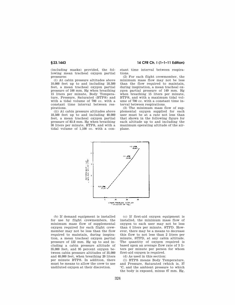
324
14 CFR Ch. I (1–1–11 Edition) § 23.1443
(including masks) provided, the fol-lowing mean tracheal oxygen partial pressures:
(i) At cabin pressure altitudes above 10,000 feet up to and including 18,500 feet, a mean tracheal oxygen partial pressure of 100 mm. Hg when breathing 15 liters per minute, Body Tempera-ture, Pressure, Saturated (BTPS) and with a tidal volume of 700 cc. with a constant time interval between res-pirations.
(ii) At cabin pressure altitudes above 18,500 feet up to and including 40,000 feet, a mean tracheal oxygen partial pressure of 83.8 mm. Hg when breathing 30 liters per minute, BTPS, and with a tidal volume of 1,100 cc. with a con-
stant time interval between respira-tions.
(2) For each flight crewmember, the minimum mass flow may not be less than the flow required to maintain, during inspiration, a mean tracheal ox-ygen partial pressure of 149 mm. Hg when breathing 15 liters per minute, BTPS, and with a maximum tidal vol-ume of 700 cc. with a constant time in-terval between respirations.
(3) The minimum mass flow of sup-plemental oxygen supplied for each user must be at a rate not less than that shown in the following figure for each altitude up to and including the maximum operating altitude of the air-plane.
(b) If demand equipment is installed for use by flight crewmembers, the minimum mass flow of supplemental oxygen required for each flight crew-member may not be less than the flow required to maintain, during inspira-tion, a mean tracheal oxygen partial pressure of 122 mm. Hg up to and in-cluding a cabin pressure altitude of 35,000 feet, and 95 percent oxygen be-tween cabin pressure altitudes of 35,000 and 40,000 feet, when breathing 20 liters per minute BTPS. In addition, there must be means to allow the crew to use undiluted oxygen at their discretion.
(c) If first-aid oxygen equipment is installed, the minimum mass flow of oxygen to each user may not be less than 4 liters per minute, STPD. How-ever, there may be a means to decrease this flow to not less than 2 liters per minute, STPD, at any cabin altitude. The quantity of oxygen required is based upon an average flow rate of 3 li-ters per minute per person for whom first-aid oxygen is required.
(d) As used in this section: (1) BTPS means Body Temperature,
and Pressure, Saturated (which is, 37 °C, and the ambient pressure to which the body is exposed, minus 47 mm. Hg,
VerDate Mar<15>2010 14:10 Mar 01, 2011 Jkt 223043 PO 00000 Frm 00334 Fmt 8010 Sfmt 8010 Y:\SGML\223043.XXX 223043 EC
28S
E91
.019
</G
PH
>
ww
oods
2 on
DS
K1D
XX
6B1P
RO
D w
ith C
FR
325
Federal Aviation Administration, DOT § 23.1449
which is the tracheal pressure dis-placed by water vapor pressure when the breathed air becomes saturated with water vapor at 37 °C).
(2) STPD means Standard, Tempera-ture, and Pressure, Dry (which is, 0 °C at 760 mm. Hg with no water vapor).
[Doc. No. 26344, 58 FR 18978, Apr. 9, 1993]
§ 23.1445 Oxygen distribution system.
(a) Except for flexible lines from oxy-gen outlets to the dispensing units, or where shown to be otherwise suitable to the installation, nonmetallic tubing must not be used for any oxygen line that is normally pressurized during flight.
(b) Nonmetallic oxygen distribution lines must not be routed where they may be subjected to elevated tempera-tures, electrical arcing, and released flammable fluids that might result from any probable failure.
[Doc. No. 26344, 58 FR 18978, Apr. 9, 1993]
§ 23.1447 Equipment standards for ox-ygen dispensing units.
If oxygen dispensing units are in-stalled, the following apply:
(a) There must be an individual dis-pensing unit for each occupant for whom supplemental oxygen is to be supplied. Each dispensing unit must:
(1) Provide for effective utilization of the oxygen being delivered to the unit.
(2) Be capable of being readily placed into position on the face of the user.
(3) Be equipped with a suitable means to retain the unit in position on the face.
(4) If radio equipment is installed, the flightcrew oxygen dispensing units must be designed to allow the use of that equipment and to allow commu-nication with any other required crew member while at their assigned duty station.
(b) If certification for operation up to and including 18,000 feet (MSL) is re-quested, each oxygen dispensing unit must:
(1) Cover the nose and mouth of the user; or
(2) Be a nasal cannula, in which case one oxygen dispensing unit covering both the nose and mouth of the user must be available. In addition, each
nasal cannula or its connecting tubing must have permanently affixed—
(i) A visible warning against smoking while in use;
(ii) An illustration of the correct method of donning; and
(iii) A visible warning against use with nasal obstructions or head colds with resultant nasal congestion.
(c) If certification for operation above 18,000 feet (MSL) is requested, each oxygen dispensing unit must cover the nose and mouth of the user.
(d) For a pressurized airplane de-signed to operate at flight altitudes above 25,000 feet (MSL), the dispensing units must meet the following:
(1) The dispensing units for pas-sengers must be connected to an oxy-gen supply terminal and be imme-diately available to each occupant wherever seated.
(2) The dispensing units for crew-members must be automatically pre-sented to each crewmember before the cabin pressure altitude exceeds 15,000 feet, or the units must be of the quick- donning type, connected to an oxygen supply terminal that is immediately available to crewmembers at their sta-tion.
(e) If certification for operation above 30,000 feet is requested, the dis-pensing units for passengers must be automatically presented to each occu-pant before the cabin pressure altitude exceeds 15,000 feet.
(f) If an automatic dispensing unit (hose and mask, or other unit) system is installed, the crew must be provided with a manual means to make the dis-pensing units immediately available in the event of failure of the automatic system.
[Amdt. 23–9, 35 FR 6387, Apr. 21, 1970, as amended by Amdt. 23–20, 42 FR 36969, July 18, 1977; Amdt. 23–30, 49 FR 7340, Feb. 28, 1984; Amdt. 23–43, 58 FR 18978, Apr. 9, 1993; Amdt. 23–49, 61 FR 5170, Feb. 9, 1996]
§ 23.1449 Means for determining use of oxygen.
There must be a means to allow the crew to determine whether oxygen is being delivered to the dispensing equip-ment.
[Amdt. 23–9, 35 FR 6387, Apr. 21, 1970]
VerDate Mar<15>2010 14:10 Mar 01, 2011 Jkt 223043 PO 00000 Frm 00335 Fmt 8010 Sfmt 8010 Y:\SGML\223043.XXX 223043ww
oods
2 on
DS
K1D
XX
6B1P
RO
D w
ith C
FR
326
14 CFR Ch. I (1–1–11 Edition) § 23.1450
§ 23.1450 Chemical oxygen generators. (a) For the purpose of this section, a
chemical oxygen generator is defined as a device which produces oxygen by chemical reaction.
(b) Each chemical oxygen generator must be designed and installed in ac-cordance with the following require-ments:
(1) Surface temperature developed by the generator during operation may not create a hazard to the airplane or to its occupants.
(2) Means must be provided to relieve any internal pressure that may be haz-ardous.
(c) In addition to meeting the re-quirements in paragraph (b) of this sec-tion, each portable chemical oxygen generator that is capable of sustained operation by successive replacement of a generator element must be placarded to show—
(1) The rate of oxygen flow, in liters per minute;
(2) The duration of oxygen flow, in minutes, for the replaceable generator element; and
(3) A warning that the replaceable generator element may be hot, unless the element construction is such that the surface temperature cannot exceed 100 °F.
[Amdt. 23–20, 42 FR 36969, July 18, 1977]
§ 23.1451 Fire protection for oxygen equipment.
Oxygen equipment and lines must: (a) Not be installed in any designed
fire zones. (b) Be protected from heat that may
be generated in, or escape from, any designated fire zone.
(c) Be installed so that escaping oxy-gen cannot come in contact with and cause ignition of grease, fluid, or vapor accumulations that are present in nor-mal operation or that may result from the failure or malfunction of any other system.
[Doc. No. 27806, 61 FR 5170, Feb. 9, 1996]
§ 23.1453 Protection of oxygen equip-ment from rupture.
(a) Each element of the oxygen sys-tem must have sufficient strength to withstand the maximum pressure and temperature, in combination with any
externally applied loads arising from consideration of limit structural loads, that may be acting on that part of the system.
(b) Oxygen pressure sources and the lines between the source and the shut-off means must be:
(1) Protected from unsafe tempera-tures; and
(2) Located where the probability and hazard of rupture in a crash landing are minimized.
[Doc. No. 27806, 61 FR 5170, Feb. 9, 1996]
§ 23.1457 Cockpit voice recorders. (a) Each cockpit voice recorder re-
quired by the operating rules of this chapter must be approved and must be installed so that it will record the fol-lowing:
(1) Voice communications trans-mitted from or received in the airplane by radio.
(2) Voice communications of flight crewmembers on the flight deck.
(3) Voice communications of flight crewmembers on the flight deck, using the airplane’s interphone system.
(4) Voice or audio signals identifying navigation or approach aids introduced into a headset or speaker.
(5) Voice communications of flight crewmembers using the passenger loud-speaker system, if there is such a sys-tem and if the fourth channel is avail-able in accordance with the require-ments of paragraph (c)(4)(ii) of this sec-tion.
(6) If datalink communication equip-ment is installed, all datalink commu-nications, using an approved data mes-sage set. Datalink messages must be recorded as the output signal from the communications unit that translates the signal into usable data.
(b) The recording requirements of paragraph (a)(2) of this section must be met by installing a cockpit-mounted area microphone, located in the best position for recording voice commu-nications originating at the first and second pilot stations and voice commu-nications of other crewmembers on the flight deck when directed to those sta-tions. The microphone must be so lo-cated and, if necessary, the pre-amplifiers and filters of the recorder must be so adjusted or supplemented,
VerDate Mar<15>2010 14:10 Mar 01, 2011 Jkt 223043 PO 00000 Frm 00336 Fmt 8010 Sfmt 8010 Y:\SGML\223043.XXX 223043ww
oods
2 on
DS
K1D
XX
6B1P
RO
D w
ith C
FR
327
Federal Aviation Administration, DOT § 23.1457
so that the intelligibility of the re-corded communications is as high as practicable when recorded under flight cockpit noise conditions and played back. Repeated aural or visual play-back of the record may be used in eval-uating intelligibility.
(c) Each cockpit voice recorder must be installed so that the part of the communication or audio signals speci-fied in paragraph (a) of this section ob-tained from each of the following sources is recorded on a separate chan-nel:
(1) For the first channel, from each boom, mask, or handheld microphone, headset, or speaker used at the first pilot station.
(2) For the second channel from each boom, mask, or handheld microphone, headset, or speaker used at the second pilot station.
(3) For the third channel—from the cockpit-mounted area microphone.
(4) For the fourth channel from: (i) Each boom, mask, or handheld
microphone, headset, or speaker used at the station for the third and fourth crewmembers.
(ii) If the stations specified in para-graph (c)(4)(i) of this section are not re-quired or if the signal at such a station is picked up by another channel, each microphone on the flight deck that is used with the passenger loudspeaker system, if its signals are not picked up by another channel.
(5) And that as far as is practicable all sounds received by the microphone listed in paragraphs (c)(1), (2), and (4) of this section must be recorded without interruption irrespective of the posi-tion of the interphone-transmitter key switch. The design shall ensure that sidetone for the flight crew is produced only when the interphone, public ad-dress system, or radio transmitters are in use.
(d) Each cockpit voice recorder must be installed so that:
(1)(i) It receives its electrical power from the bus that provides the max-imum reliability for operation of the cockpit voice recorder without jeopard-izing service to essential or emergency loads.
(ii) It remains powered for as long as possible without jeopardizing emer-gency operation of the airplane.
(2) There is an automatic means to simultaneously stop the recorder and prevent each erasure feature from func-tioning, within 10 minutes after crash impact; and
(3) There is an aural or visual means for preflight checking of the recorder for proper operation;
(4) Any single electrical failure exter-nal to the recorder does not disable both the cockpit voice recorder and the flight data recorder;
(5) It has an independent power source—
(i) That provides 10 ± 1 minutes of electrical power to operate both the cockpit voice recorder and cockpit- mounted area microphone;
(ii) That is located as close as prac-ticable to the cockpit voice recorder; and
(iii) To which the cockpit voice re-corder and cockpit-mounted area microphone are switched automati-cally in the event that all other power to the cockpit voice recorder is inter-rupted either by normal shutdown or by any other loss of power to the elec-trical power bus; and
(6) It is in a separate container from the flight data recorder when both are required. If used to comply with only the cockpit voice recorder require-ments, a combination unit may be in-stalled.
(e) The recorder container must be located and mounted to minimize the probability of rupture of the container as a result of crash impact and con-sequent heat damage to the recorder from fire.
(1) Except as provided in paragraph (e)(2) of this section, the recorder con-tainer must be located as far aft as practicable, but need not be outside of the pressurized compartment, and may not be located where aft-mounted en-gines may crush the container during impact.
(2) If two separate combination dig-ital flight data recorder and cockpit voice recorder units are installed in-stead of one cockpit voice recorder and one digital flight data recorder, the combination unit that is installed to comply with the cockpit voice recorder requirements may be located near the cockpit.
VerDate Mar<15>2010 14:10 Mar 01, 2011 Jkt 223043 PO 00000 Frm 00337 Fmt 8010 Sfmt 8010 Y:\SGML\223043.XXX 223043ww
oods
2 on
DS
K1D
XX
6B1P
RO
D w
ith C
FR

328
14 CFR Ch. I (1–1–11 Edition) § 23.1459
(f) If the cockpit voice recorder has a bulk erasure device, the installation must be designed to minimize the prob-ability of inadvertent operation and ac-tuation of the device during crash im-pact.
(g) Each recorder container must: (1) Be either bright orange or bright
yellow; (2) Have reflective tape affixed to its
external surface to facilitate its loca-tion under water; and
(3) Have an underwater locating de-vice, when required by the operating rules of this chapter, on or adjacent to the container which is secured in such manner that they are not likely to be separated during crash impact.
[Amdt. 23–35, 53 FR 26142, July 11, 1988, as amended by Amdt. No. 23–58, 73 FR 12562, Mar. 7, 2008; 74 FR 32799, July 9, 2009]
§ 23.1459 Flight data recorders.
(a) Each flight recorder required by the operating rules of this chapter must be installed so that:
(1) It is supplied with airspeed, alti-tude, and directional data obtained from sources that meet the accuracy requirements of §§ 23.1323, 23.1325, and 23.1327, as appropriate;
(2) The vertical acceleration sensor is rigidly attached, and located longitu-dinally either within the approved cen-ter of gravity limits of the airplane, or at a distance forward or aft of these limits that does not exceed 25 percent of the airplane’s mean aerodynamic chord;
(3)(i) It receives its electrical power from the bus that provides the max-imum reliability for operation of the flight data recorder without jeopard-izing service to essential or emergency loads.
(ii) It remains powered for as long as possible without jeopardizing emer-gency operation of the airplane.
(4) There is an aural or visual means for preflight checking of the recorder for proper recording of data in the stor-age medium;
(5) Except for recorders powered sole-ly by the engine-driven electrical gen-erator system, there is an automatic means to simultaneously stop a re-corder that has a data erasure feature and prevent each erasure feature from
functioning, within 10 minutes after crash impact;
(6) Any single electrical failure exter-nal to the recorder does not disable both the cockpit voice recorder and the flight data recorder; and
(7) It is in a separate container from the cockpit voice recorder when both are required. If used to comply with only the flight data recorder require-ments, a combination unit may be in-stalled. If a combination unit is in-stalled as a cockpit voice recorder to comply with § 23.1457(e)(2), a combina-tion unit must be used to comply with this flight data recorder requirement.
(b) Each nonejectable record con-tainer must be located and mounted so as to minimize the probability of con-tainer rupture resulting from crash im-pact and subsequent damage to the record from fire. In meeting this re-quirement the record container must be located as far aft as practicable, but need not be aft of the pressurized com-partment, and may not be where aft- mounted engines may crush the con-tainer upon impact.
(c) A correlation must be established between the flight recorder readings of airspeed, altitude, and heading and the corresponding readings (taking into ac-count correction factors) of the first pi-lot’s instruments. The correlation must cover the airspeed range over which the airplane is to be operated, the range of altitude to which the air-plane is limited, and 360 degrees of heading. Correlation may be estab-lished on the ground as appropriate.
(d) Each recorder container must: (1) Be either bright orange or bright
yellow; (2) Have reflective tape affixed to its
external surface to facilitate its loca-tion under water; and
(3) Have an underwater locating de-vice, when required by the operating rules of this chapter, on or adjacent to the container which is secured in such a manner that they are not likely to be separated during crash impact.
(e) Any novel or unique design or operational characteristics of the air-craft shall be evaluated to determine if
VerDate Mar<15>2010 14:10 Mar 01, 2011 Jkt 223043 PO 00000 Frm 00338 Fmt 8010 Sfmt 8010 Y:\SGML\223043.XXX 223043ww
oods
2 on
DS
K1D
XX
6B1P
RO
D w
ith C
FR

329
Federal Aviation Administration, DOT § 23.1507
any dedicated parameters must be re-corded on flight recorders in addition to or in place of existing requirements.
[Amdt. 23–35, 53 FR 26143, July 11, 1988, as amended by Amdt. No. 23–58, 73 FR 12562, Mar. 7, 2008; 74 FR 32800, July 9, 2009]
§ 23.1461 Equipment containing high energy rotors.
(a) Equipment, such as Auxiliary Power Units (APU) and constant speed drive units, containing high energy ro-tors must meet paragraphs (b), (c), or (d) of this section.
(b) High energy rotors contained in equipment must be able to withstand damage caused by malfunctions, vibra-tion, abnormal speeds, and abnormal temperatures. In addition—
(1) Auxiliary rotor cases must be able to contain damage caused by the fail-ure of high energy rotor blades; and
(2) Equipment control devices, sys-tems, and instrumentation must rea-sonably ensure that no operating limi-tations affecting the integrity of high energy rotors will be exceeded in serv-ice.
(c) It must be shown by test that equipment containing high energy ro-tors can contain any failure of a high energy rotor that occurs at the highest speed obtainable with the normal speed control devices inoperative.
(d) Equipment containing high en-ergy rotors must be located where rotor failure will neither endanger the occupants nor adversely affect contin-ued safe flight.
[Amdt. 23–20, 42 FR 36969, July 18, 1977, as amended by Amdt. 23–49, 61 FR 5170, Feb. 9, 1996]
Subpart G—Operating Limitations and Information
§ 23.1501 General. (a) Each operating limitation speci-
fied in §§ 23.1505 through 23.1527 and other limitations and information nec-essary for safe operation must be es-tablished.
(b) The operating limitations and other information necessary for safe operation must be made available to the crewmembers as prescribed in §§ 23.1541 through 23.1589.
[Amdt. 23–21, 43 FR 2319, Jan. 16, 1978]
§ 23.1505 Airspeed limitations.
(a) The never-exceed speed VNE must be established so that it is—
(1) Not less than 0.9 times the min-imum value of VD allowed under § 23.335; and
(2) Not more than the lesser of— (i) 0.9 VD established under § 23.335; or (ii) 0.9 times the maximum speed
shown under § 23.251. (b) The maximum structural cruising
speed VNO must be established so that it is—
(1) Not less than the minimum value of VC allowed under § 23.335; and
(2) Not more than the lesser of— (i) VC established under § 23.335; or (ii) 0.89 VNE established under para-
graph (a) of this section. (c) Paragraphs (a) and (b) of this sec-
tion do not apply to turbine airplanes or to airplanes for which a design div-ing speed VD/MD is established under § 23.335(b)(4). For those airplanes, a maximum operating limit speed (VMO/ MMO-airspeed or Mach number, which-ever is critical at a particular altitude) must be established as a speed that may not be deliberately exceeded in any regime of flight (climb, cruise, or descent) unless a higher speed is au-thorized for flight test or pilot training operations. VMO/MMO must be estab-lished so that it is not greater than the design cruising speed VC/MC and so that it is sufficiently below VD/MD and the maximum speed shown under § 23.251 to make it highly improbable that the latter speeds will be inadvertently ex-ceeded in operations. The speed margin between VMO/MMO and VD/MD or the maximum speed shown under § 23.251 may not be less than the speed margin established between VC/MC and VD/MD under § 23.335(b), or the speed margin found necessary in the flight test con-ducted under § 23.253.
[Doc. No. 4080, 29 FR 17955, Dec. 18, 1964, as amended by Amdt. 23–7, 34 FR 13096, Aug. 13, 1969]
§ 23.1507 Operating maneuvering speed.
The maximum operating maneu-vering speed, VO, must be established
VerDate Mar<15>2010 14:10 Mar 01, 2011 Jkt 223043 PO 00000 Frm 00339 Fmt 8010 Sfmt 8010 Y:\SGML\223043.XXX 223043ww
oods
2 on
DS
K1D
XX
6B1P
RO
D w
ith C
FR

330
14 CFR Ch. I (1–1–11 Edition) § 23.1511
as an operating limitation. VO is a se-lected speed that is not greater than VS√n established in § 23.335(c).
[Doc. No. 26269, 58 FR 42165, Aug. 6, 1993]
§ 23.1511 Flap extended speed. (a) The flap extended speed VFE must
be established so that it is— (1) Not less than the minimum value
of VF allowed in § 23.345(b); and (2) Not more than VF established
under § 23.345(a), (c), and (d). (b) Additional combinations of flap
setting, airspeed, and engine power may be established if the structure has been proven for the corresponding de-sign conditions.
[Doc. No. 4080, 29 FR 17955, Dec. 18, 1964; 30 FR 258, Jan. 9, 1965, as amended by Amdt. 23– 50, 61 FR 5192, Feb. 9, 1996]
§ 23.1513 Minimum control speed. The minimum control speed VMC, de-
termined under § 23.149, must be estab-lished as an operating limitation.
§ 23.1519 Weight and center of gravity. The weight and center of gravity lim-
itations determined under § 23.23 must be established as operating limitations.
§ 23.1521 Powerplant limitations. (a) General. The powerplant limita-
tions prescribed in this section must be established so that they do not exceed the corresponding limits for which the engines or propellers are type certifi-cated. In addition, other powerplant limitations used in determining com-pliance with this part must be estab-lished.
(b) Takeoff operation. The powerplant takeoff operation must be limited by—
(1) The maximum rotational speed (rpm);
(2) The maximum allowable manifold pressure (for reciprocating engines);
(3) The maximum allowable gas tem-perature (for turbine engines);
(4) The time limit for the use of the power or thrust corresponding to the limitations established in paragraphs (b)(1) through (3) of this section; and
(5) The maximum allowable cylinder head (as applicable), liquid coolant and oil temperatures.
(c) Continuous operation. The contin-uous operation must be limited by—
(1) The maximum rotational speed; (2) The maximum allowable manifold
pressure (for reciprocating engines); (3) The maximum allowable gas tem-
perature (for turbine engines); and (4) The maximum allowable cylinder
head, oil, and liquid coolant tempera-tures.
(d) Fuel grade or designation. The min-imum fuel grade (for reciprocating en-gines), or fuel designation (for turbine engines), must be established so that it is not less than that required for the operation of the engines within the limitations in paragraphs (b) and (c) of this section.
(e) Ambient temperature. For all air-planes except reciprocating engine- powered airplanes of 6,000 pounds or less maximum weight, ambient tem-perature limitations (including limita-tions for winterization installations if applicable) must be established as the maximum ambient atmospheric tem-perature at which compliance with the cooling provisions of §§ 23.1041 through 23.1047 is shown.
[Doc. No. 4080, 29 FR 17955, Dec. 18, 1964; 30 FR 258, Jan. 9, 1965, as amended by Amdt. 23– 21, 43 FR 2319, Jan. 16, 1978; Amdt. 23–45, 58 FR 42165, Aug. 6, 1993; Amdt. 23–50, 61 FR 5192, Feb. 9, 1996]
§ 23.1522 Auxiliary power unit limita-tions.
If an auxiliary power unit is in-stalled, the limitations established for the auxiliary power must be specified in the operating limitations for the air-plane.
[Doc. No. 26269, 58 FR 42166, Aug. 6, 1993]
§ 23.1523 Minimum flight crew. The minimum flight crew must be es-
tablished so that it is sufficient for safe operation considering—
(a) The workload on individual crew-members and, in addition for com-muter category airplanes, each crew-member workload determination must consider the following:
(1) Flight path control, (2) Collision avoidance, (3) Navigation, (4) Communications, (5) Operation and monitoring of all
essential airplane systems, (6) Command decisions, and
VerDate Mar<15>2010 14:10 Mar 01, 2011 Jkt 223043 PO 00000 Frm 00340 Fmt 8010 Sfmt 8010 Y:\SGML\223043.XXX 223043ww
oods
2 on
DS
K1D
XX
6B1P
RO
D w
ith C
FR
331
Federal Aviation Administration, DOT § 23.1545
(7) The accessibility and ease of oper-ation of necessary controls by the ap-propriate crewmember during all nor-mal and emergency operations when at the crewmember flight station;
(b) The accessibility and ease of oper-ation of necessary controls by the ap-propriate crewmember; and
(c) The kinds of operation authorized under § 23.1525.
[Amdt. 23–21, 43 FR 2319, Jan. 16, 1978, as amended by Amdt. 23–34, 52 FR 1834, Jan. 15, 1987]
§ 23.1524 Maximum passenger seating configuration.
The maximum passenger seating con-figuration must be established.
[Amdt. 23–10, 36 FR 2864, Feb. 11, 1971]
§ 23.1525 Kinds of operation.
The kinds of operation authorized (e.g. VFR, IFR, day or night) and the meteorological conditions (e.g. icing) to which the operation of the airplane is limited or from which it is prohib-ited, must be established appropriate to the installed equipment.
[Doc. No. 26269, 58 FR 42166, Aug. 6, 1993]
§ 23.1527 Maximum operating altitude.
(a) The maximum altitude up to which operation is allowed, as limited by flight, structural, powerplant, func-tional or equipment characteristics, must be established.
(b) A maximum operating altitude limitation of not more than 25,000 feet must be established for pressurized air-planes unless compliance with § 23.775(e) is shown.
[Doc. No. 26269, 58 FR 42166, Aug. 6, 1993]
§ 23.1529 Instructions for Continued Airworthiness.
The applicant must prepare Instruc-tions for Continued Airworthiness in accordance with appendix G to this part that are acceptable to the Admin-istrator. The instructions may be in-complete at type certification if a pro-gram exists to ensure their completion prior to delivery of the first airplane or issuance of a standard certificate of airworthiness, whichever occurs later.
[Amdt. 23–26, 45 FR 60171, Sept. 11, 1980]
MARKINGS AND PLACARDS
§ 23.1541 General. (a) The airplane must contain— (1) The markings and placards speci-
fied in §§ 23.1545 through 23.1567; and (2) Any additional information, in-
strument markings, and placards re-quired for the safe operation if it has unusual design, operating, or handling characteristics.
(b) Each marking and placard pre-scribed in paragraph (a) of this sec-tion—
(1) Must be displayed in a con-spicuous place; and
(2) May not be easily erased, dis-figured, or obscured.
(c) For airplanes which are to be cer-tificated in more than one category—
(1) The applicant must select one cat-egory upon which the placards and markings are to be based; and
(2) The placards and marking infor-mation for all categories in which the airplane is to be certificated must be furnished in the Airplane Flight Man-ual.
[Doc. No. 4080, 29 FR 17955, Dec. 18, 1964; 30 FR 258, Jan. 9, 1965, as amended by Amdt. 23– 21, 43 FR 2319, Jan. 16, 1978]
§ 23.1543 Instrument markings: Gen-eral.
For each instrument— (a) When markings are on the cover
glass of the instrument, there must be means to maintain the correct align-ment of the glass cover with the face of the dial; and
(b) Each arc and line must be wide enough and located to be clearly visi-ble to the pilot.
(c) All related instruments must be calibrated in compatible units.
[Doc. No. 4080, 29 FR 17955, Dec. 18, 1964; 30 FR 258, Jan. 9, 1965, as amended by Amdt. 23– 50, 61 FR 5192, Feb. 9, 1996]
§ 23.1545 Airspeed indicator. (a) Each airspeed indicator must be
marked as specified in paragraph (b) of this section, with the marks located at the corresponding indicated airspeeds.
(b) The following markings must be made:
(1) For the never-exceed speed VNE, a radial red line.
VerDate Mar<15>2010 14:10 Mar 01, 2011 Jkt 223043 PO 00000 Frm 00341 Fmt 8010 Sfmt 8010 Y:\SGML\223043.XXX 223043ww
oods
2 on
DS
K1D
XX
6B1P
RO
D w
ith C
FR

332
14 CFR Ch. I (1–1–11 Edition) § 23.1547
(2) For the caution range, a yellow arc extending from the red line speci-fied in paragraph (b)(1) of this section to the upper limit of the green arc specified in paragraph (b)(3) of this sec-tion.
(3) For the normal operating range, a green arc with the lower limit at VS1 with maximum weight and with land-ing gear and wing flaps retracted, and the upper limit at the maximum struc-tural cruising speed VNO established under § 23.1505(b).
(4) For the flap operating range, a white arc with the lower limit at VS0 at the maximum weight, and the upper limit at the flaps-extended speed VFE established under § 23.1511.
(5) For reciprocating multiengine- powered airplanes of 6,000 pounds or less maximum weight, for the speed at which compliance has been shown with § 23.69(b) relating to rate of climb at maximum weight and at sea level, a blue radial line.
(6) For reciprocating multiengine- powered airplanes of 6,000 pounds or less maximum weight, for the max-imum value of minimum control speed, VMC, (one-engine-inoperative) deter-mined under § 23.149(b), a red radial line.
(c) If VNE or VNO vary with altitude, there must be means to indicate to the pilot the appropriate limitations throughout the operating altitude range.
(d) Paragraphs (b)(1) through (b)(3) and paragraph (c) of this section do not apply to aircraft for which a maximum operating speed VMO/MMO is estab-lished under § 23.1505(c). For those air-craft there must either be a maximum allowable airspeed indication showing the variation of VMO/MMO with altitude or compressibility limitations (as ap-propriate), or a radial red line marking for VMO/MMO must be made at lowest value of VMO/MMO established for any altitude up to the maximum operating altitude for the airplane.
[Doc. No. 4080, 29 FR 17955, Dec. 18, 1964, as amended by Amdt. 23–3, 30 FR 14240, Nov. 13, 1965; Amdt. 23–7, 34 FR 13097, Aug. 13, 1969; Amdt. 23–23, 43 FR 50593, Oct. 30, 1978; Amdt. 23–50, 61 FR 5193, Feb. 9, 1996]
§ 23.1547 Magnetic direction indicator.
(a) A placard meeting the require-ments of this section must be installed on or near the magnetic direction indi-cator.
(b) The placard must show the cali-bration of the instrument in level flight with the engines operating.
(c) The placard must state whether the calibration was made with radio re-ceivers on or off.
(d) Each calibration reading must be in terms of magnetic headings in not more than 30 degree increments.
(e) If a magnetic nonstabilized direc-tion indicator can have a deviation of more than 10 degrees caused by the op-eration of electrical equipment, the placard must state which electrical loads, or combination of loads, would cause a deviation of more than 10 de-grees when turned on.
[Doc. No. 4080, 29 FR 17955, Dec. 18, 1964; 30 FR 258, Jan. 9, 1965, as amended by Amdt. 23– 20, 42 FR 36969, July 18, 1977]
§ 23.1549 Powerplant and auxiliary power unit instruments.
For each required powerplant and auxiliary power unit instrument, as ap-propriate to the type of instruments—
(a) Each maximum and, if applicable, minimum safe operating limit must be marked with a red radial or a red line;
(b) Each normal operating range must be marked with a green arc or green line, not extending beyond the maximum and minimum safe limits;
(c) Each takeoff and precautionary range must be marked with a yellow arc or a yellow line; and
(d) Each engine, auxiliary power unit, or propeller range that is re-stricted because of excessive vibration stresses must be marked with red arcs or red lines.
[Amdt. 23–12, 41 FR 55466, Dec. 20, 1976, as amended by Amdt. 23–28, 47 FR 13315, Mar. 29, 1982; Amdt. 23–45, 58 FR 42166, Aug. 6, 1993]
§ 23.1551 Oil quantity indicator.
Each oil quantity indicator must be marked in sufficient increments to in-dicate readily and accurately the quan-tity of oil.
VerDate Mar<15>2010 14:10 Mar 01, 2011 Jkt 223043 PO 00000 Frm 00342 Fmt 8010 Sfmt 8010 Y:\SGML\223043.XXX 223043ww
oods
2 on
DS
K1D
XX
6B1P
RO
D w
ith C
FR

333
Federal Aviation Administration, DOT § 23.1557
§ 23.1553 Fuel quantity indicator.
A red radial line must be marked on each indicator at the calibrated zero reading, as specified in § 23.1337(b)(1).
[Doc. No. 27807, 61 FR 5193, Feb. 9, 1996]
§ 23.1555 Control markings.
(a) Each cockpit control, other than primary flight controls and simple push button type starter switches, must be plainly marked as to its func-tion and method of operation.
(b) Each secondary control must be suitably marked.
(c) For powerplant fuel controls— (1) Each fuel tank selector control
must be marked to indicate the posi-tion corresponding to each tank and to each existing cross feed position;
(2) If safe operation requires the use of any tanks in a specific sequence, that sequence must be marked on or near the selector for those tanks;
(3) The conditions under which the full amount of usable fuel in any re-stricted usage fuel tank can safely be used must be stated on a placard adja-cent to the selector valve for that tank; and
(4) Each valve control for any engine of a multiengine airplane must be marked to indicate the position cor-responding to each engine controlled.
(d) Usable fuel capacity must be marked as follows:
(1) For fuel systems having no selec-tor controls, the usable fuel capacity of the system must be indicated at the fuel quantity indicator.
(2) For fuel systems having selector controls, the usable fuel capacity available at each selector control posi-tion must be indicated near the selec-tor control.
(e) For accessory, auxiliary, and emergency controls—
(1) If retractable landing gear is used, the indicator required by § 23.729 must be marked so that the pilot can, at any time, ascertain that the wheels are se-cured in the extreme positions; and
(2) Each emergency control must be red and must be marked as to method of operation. No control other than an emergency control, or a control that serves an emergency function in addi-
tion to its other functions, shall be this color.
[Doc. No. 4080, 29 FR 17955, Dec. 18, 1964; 30 FR 258, Jan. 9, 1965, as amended by Amdt. 23– 21, 43 FR 2319, Jan. 16, 1978; Amdt. 23–50, 61 FR 5193, Feb. 9, 1996]
§ 23.1557 Miscellaneous markings and placards.
(a) Baggage and cargo compartments, and ballast location. Each baggage and cargo compartment, and each ballast location, must have a placard stating any limitations on contents, including weight, that are necessary under the loading requirements.
(b) Seats. If the maximum allowable weight to be carried in a seat is less than 170 pounds, a placard stating the lesser weight must be permanently at-tached to the seat structure.
(c) Fuel, oil, and coolant filler open-ings. The following apply:
(1) Fuel filler openings must be marked at or near the filler cover with—
(i) For reciprocating engine-powered airplanes—
(A) The word ‘‘Avgas’’; and (B) The minimum fuel grade. (ii) For turbine engine-powered air-
planes— (A) The words ‘‘Jet Fuel’’; and (B) The permissible fuel designations,
or references to the Airplane Flight Manual (AFM) for permissible fuel des-ignations.
(iii) For pressure fueling systems, the maximum permissible fueling supply pressure and the maximum permissible defueling pressure.
(2) Oil filler openings must be marked at or near the filler cover with the word ‘‘Oil’’ and the permissible oil designations, or references to the Air-plane Flight Manual (AFM) for permis-sible oil designations.
(3) Coolant filler openings must be marked at or near the filler cover with the word ‘‘Coolant’’.
(d) Emergency exit placards. Each placard and operating control for each emergency exit must be red. A placard must be near each emergency exit con-trol and must clearly indicate the loca-tion of that exit and its method of op-eration.
(e) The system voltage of each direct current installation must be clearly
VerDate Mar<15>2010 14:10 Mar 01, 2011 Jkt 223043 PO 00000 Frm 00343 Fmt 8010 Sfmt 8010 Y:\SGML\223043.XXX 223043ww
oods
2 on
DS
K1D
XX
6B1P
RO
D w
ith C
FR
334
14 CFR Ch. I (1–1–11 Edition) § 23.1559
marked adjacent to its exernal power connection.
[Doc. No. 4080, 29 FR 17955, Dec. 18, 1964; as amended by Amdt. 23–21, 42 FR 15042, Mar. 17, 1977; Amdt. 23–23, 43 FR 50594, Oct. 30, 1978; Amdt. 23–45, 58 FR 42166, Aug. 6, 1993; 73 FR 35063, June 20, 2008]
§ 23.1559 Operating limitations placard.
(a) There must be a placard in clear view of the pilot stating—
(1) That the airplane must be oper-ated in accordance with the Airplane Flight Manual; and
(2) The certification category of the airplane to which the placards apply.
(b) For airplanes certificated in more than one category, there must be a placard in clear view of the pilot stat-ing that other limitations are con-tained in the Airplane Flight Manual.
(c) There must be a placard in clear view of the pilot that specifies the kind of operations to which the operation of the airplane is limited or from which it is prohibited under § 23.1525.
[Doc. No. 27807, 61 FR 5193, Feb. 9, 1996]
§ 23.1561 Safety equipment.
(a) Safety equipment must be plainly marked as to method of operation.
(b) Stowage provisions for required safety equipment must be marked for the benefit of occupants.
§ 23.1563 Airspeed placards.
There must be an airspeed placard in clear view of the pilot and as close as practicable to the airspeed indicator. This placard must list—
(a) The operating maneuvering speed, VO; and
(b) The maximum landing gear oper-ating speed VLO.
(c) For reciprocating multiengine- powered airplanes of more than 6,000 pounds maximum weight, and turbine engine-powered airplanes, the max-imum value of the minimum control speed, VMC (one-engine-inoperative) de-termined under § 23.149(b).
[Amdt. 23–7, 34 FR 13097, Aug. 13, 1969, as amended by Amdt. 23–45, 58 FR 42166, Aug. 6, 1993; Amdt. 23–50, 61 FR 5193, Feb. 9, 1996]
§ 23.1567 Flight maneuver placard.
(a) For normal category airplanes, there must be a placard in front of and in clear view of the pilot stating: ‘‘No acrobatic maneuvers, including spins, approved.’’
(b) For utility category airplanes, there must be—
(1) A placard in clear view of the pilot stating: ‘‘Acrobatic maneuvers are limited to the following lllllllllll;’’ (list approved maneuvers and the recommended entry speed for each); and
(2) For those airplanes that do not meet the spin requirements for acro-batic category airplanes, an additional placard in clear view of the pilot stat-ing: ‘‘Spins Prohibited.’’
(c) For acrobatic category airplanes, there must be a placard in clear view of the pilot listing the approved acrobatic maneuvers and the recommended entry airspeed for each. If inverted flight ma-neuvers are not approved, the placard must bear a notation to this effect.
(d) For acrobatic category airplanes and utility category airplanes approved for spinning, there must be a placard in clear view of the pilot—
(1) Listing the control actions for re-covery from spinning maneuvers; and
(2) Stating that recovery must be ini-tiated when spiral characteristics ap-pear, or after not more than six turns or not more than any greater number of turns for which the airplane has been certificated.
[Doc. No. 4080, 29 FR 17955, Dec. 18, 1964; 30 FR 258, Jan. 9, 1965, as amended by Amdt. 23– 13, 37 FR 20023, Sept. 23, 1972; Amdt. 23–21, 43 FR 2319, Jan. 16, 1978; Amdt. 23–50, 61 FR 5193, Feb. 9, 1996]
AIRPLANE FLIGHT MANUAL AND APPROVED MANUAL MATERIAL
§ 23.1581 General.
(a) Furnishing information. An Air-plane Flight Manual must be furnished with each airplane, and it must contain the following:
(1) Information required by §§ 23.1583 through 23.1589.
(2) Other information that is nec-essary for safe operation because of de-sign, operating, or handling character-istics.
VerDate Mar<15>2010 14:10 Mar 01, 2011 Jkt 223043 PO 00000 Frm 00344 Fmt 8010 Sfmt 8010 Y:\SGML\223043.XXX 223043ww
oods
2 on
DS
K1D
XX
6B1P
RO
D w
ith C
FR

335
Federal Aviation Administration, DOT § 23.1583
(3) Further information necessary to comply with the relevant operating rules.
(b) Approved information. (1) Except as provided in paragraph (b)(2) of this sec-tion, each part of the Airplane Flight Manual containing information pre-scribed in §§ 23.1583 through 23.1589 must be approved, segregated, identi-fied and clearly distinguished from each unapproved part of that Airplane Flight Manual.
(2) The requirements of paragraph (b)(1) of this section do not apply to re-ciprocating engine-powered airplanes of 6,000 pounds or less maximum weight, if the following is met:
(i) Each part of the Airplane Flight Manual containing information pre-scribed in § 23.1583 must be limited to such information, and must be ap-proved, identified, and clearly distin-guished from each other part of the Airplane Flight Manual.
(ii) The information prescribed in §§ 23.1585 through 23.1589 must be deter-mined in accordance with the applica-ble requirements of this part and pre-sented in its entirety in a manner ac-ceptable to the Administrator.
(3) Each page of the Airplane Flight Manual containing information pre-scribed in this section must be of a type that is not easily erased, dis-figured, or misplaced, and is capable of being inserted in a manual provided by the applicant, or in a folder, or in any other permanent binder.
(c) The units used in the Airplane Flight Manual must be the same as those marked on the appropriate in-struments and placards.
(d) All Airplane Flight Manual oper-ational airspeeds, unless otherwise specified, must be presented as indi-cated airspeeds.
(e) Provision must be made for stow-ing the Airplane Flight Manual in a suitable fixed container which is read-ily accessible to the pilot.
(f) Revisions and amendments. Each Airplane Flight Manual (AFM) must contain a means for recording the in-corporation of revisions and amend-ments.
[Amdt. 23–21, 43 FR 2319, Jan. 16, 1978, as amended by Amdt. 23–34, 52 FR 1834, Jan. 15, 1987; Amdt. 23–45, 58 FR 42166, Aug. 6, 1993; Amdt. 23–50, 61 FR 5193, Feb. 9, 1996]
§ 23.1583 Operating limitations. The Airplane Flight Manual must
contain operating limitations deter-mined under this part 23, including the following—
(a) Airspeed limitations. The following information must be furnished:
(1) Information necessary for the marking of the airspeed limits on the indicator as required in § 23.1545, and the significance of each of those limits and of the color coding used on the in-dicator.
(2) The speeds VMC, VO, VLE, and VLO, if established, and their significance.
(3) In addition, for turbine powered commuter category airplanes—
(i) The maximum operating limit speed, VMO/MMO and a statement that this speed must not be deliberately ex-ceeded in any regime of flight (climb, cruise or descent) unless a higher speed is authorized for flight test or pilot training;
(ii) If an airspeed limitation is based upon compressibility effects, a state-ment to this effect and information as to any symptoms, the probable behav-ior of the airplane, and the rec-ommended recovery procedures; and
(iii) The airspeed limits must be shown in terms of VMO/MMO instead of VNO and VNE.
(b) Powerplant limitations. The fol-lowing information must be furnished:
(1) Limitations required by § 23.1521. (2) Explanation of the limitations,
when appropriate. (3) Information necessary for mark-
ing the instruments required by § 23.1549 through § 23.1553.
(c) Weight. The airplane flight man-ual must include—
(1) The maximum weight; and (2) The maximum landing weight, if
the design landing weight selected by the applicant is less than the max-imum weight.
(3) For normal, utility, and acrobatic category reciprocating engine-powered airplanes of more than 6,000 pounds maximum weight and for turbine en-gine-powered airplanes in the normal, utility, and acrobatic category, per-formance operating limitations as fol-lows—
(i) The maximum takeoff weight for each airport altitude and ambient tem-perature within the range selected by
VerDate Mar<15>2010 14:10 Mar 01, 2011 Jkt 223043 PO 00000 Frm 00345 Fmt 8010 Sfmt 8010 Y:\SGML\223043.XXX 223043ww
oods
2 on
DS
K1D
XX
6B1P
RO
D w
ith C
FR
336
14 CFR Ch. I (1–1–11 Edition) § 23.1583
the applicant at which the airplane complies with the climb requirements of § 23.63(c)(1).
(ii) The maximum landing weight for each airport altitude and ambient tem-perature within the range selected by the applicant at which the airplane complies with the climb requirements of § 23.63(c)(2).
(4) For commuter category airplanes, the maximum takeoff weight for each airport altitude and ambient tempera-ture within the range selected by the applicant at which—
(i) The airplane complies with the climb requirements of § 23.63(d)(1); and
(ii) The accelerate-stop distance de-termined under § 23.55 is equal to the available runway length plus the length of any stopway, if utilized; and either:
(iii) The takeoff distance determined under § 23.59(a) is equal to the available runway length; or
(iv) At the option of the applicant, the takeoff distance determined under § 23.59(a) is equal to the available run-way length plus the length of any clearway and the takeoff run deter-mined under § 23.59(b) is equal to the available runway length.
(5) For commuter category airplanes, the maximum landing weight for each airport altitude within the range se-lected by the applicant at which—
(i) The airplane complies with the climb requirements of § 23.63(d)(2) for ambient temperatures within the range selected by the applicant; and
(ii) The landing distance determined under § 23.75 for standard temperatures is equal to the available runway length.
(6) The maximum zero wing fuel weight, where relevant, as established in accordance with § 23.343.
(d) Center of gravity. The established center of gravity limits.
(e) Maneuvers. The following author-ized maneuvers, appropriate airspeed limitations, and unauthorized maneu-vers, as prescribed in this section.
(1) Normal category airplanes. No acro-batic maneuvers, including spins, are authorized.
(2) Utility category airplanes. A list of authorized maneuvers demonstrated in the type flight tests, together with rec-ommended entry speeds and any other
associated limitations. No other ma-neuver is authorized.
(3) Acrobatic category airplanes. A list of approved flight maneuvers dem-onstrated in the type flight tests, to-gether with recommended entry speeds and any other associated limitations.
(4) Acrobatic category airplanes and utility category airplanes approved for spinning. Spin recovery procedure es-tablished to show compliance with § 23.221(c).
(5) Commuter category airplanes. Ma-neuvers are limited to any maneuver incident to normal flying, stalls, (ex-cept whip stalls) and steep turns in which the angle of bank is not more than 60 degrees.
(f) Maneuver load factor. The positive limit load factors in g’s, and, in addi-tion, the negative limit load factor for acrobatic category airplanes.
(g) Minimum flight crew. The number and functions of the minimum flight crew determined under § 23.1523.
(h) Kinds of operation. A list of the kinds of operation to which the air-plane is limited or from which it is pro-hibited under § 23.1525, and also a list of installed equipment that affects any operating limitation and identification as to the equipment’s required oper-ational status for the kinds of oper-ation for which approval has been given.
(i) Maximum operating altitude. The maximum altitude established under § 23.1527.
(j) Maximum passenger seating configu-ration. The maximum passenger seating configuration.
(k) Allowable lateral fuel loading. The maximum allowable lateral fuel load-ing differential, if less than the max-imum possible.
(l) Baggage and cargo loading. The fol-lowing information for each baggage and cargo compartment or zone—
(1) The maximum allowable load; and (2) The maximum intensity of load-
ing. (m) Systems. Any limitations on the
use of airplane systems and equipment. (n) Ambient temperatures. Where ap-
propriate, maximum and minimum am-bient air temperatures for operation.
(o) Smoking. Any restrictions on smoking in the airplane.
VerDate Mar<15>2010 14:10 Mar 01, 2011 Jkt 223043 PO 00000 Frm 00346 Fmt 8010 Sfmt 8010 Y:\SGML\223043.XXX 223043ww
oods
2 on
DS
K1D
XX
6B1P
RO
D w
ith C
FR

337
Federal Aviation Administration, DOT § 23.1585
(p) Types of surface. A statement of the types of surface on which oper-ations may be conducted. (See § 23.45(g) and § 23.1587 (a)(4), (c)(2), and (d)(4)).
[Doc. No. 4080, 29 FR 17955, Dec. 18, 1964, as amended by Amdt. 23–7, 34 FR 13097, Aug. 13, 1969; Amdt. 23–10, 36 FR 2864, Feb. 11, 1971; Amdt. 23–21, 43 FR 2320, Jan. 16, 1978; Amdt. 23–23, 43 FR 50594, Oct. 30, 1978; Amdt. 23–34, 52 FR 1834, Jan. 15, 1987; Amdt. 23–45, 58 FR 42166, Aug. 6, 1993; Amdt. 23–50, 61 FR 5193, Feb. 9, 1996]
§ 23.1585 Operating procedures. (a) For all airplanes, information
concerning normal, abnormal (if appli-cable), and emergency procedures and other pertinent information necessary for safe operation and the achievement of the scheduled performance must be furnished, including—
(1) An explanation of significant or unusual flight or ground handling char-acteristics;
(2) The maximum demonstrated val-ues of crosswind for takeoff and land-ing, and procedures and information pertinent to operations in crosswinds;
(3) A recommended speed for flight in rough air. This speed must be chosen to protect against the occurrence, as a re-sult of gusts, of structural damage to the airplane and loss of control (for ex-ample, stalling);
(4) Procedures for restarting any tur-bine engine in flight, including the ef-fects of altitude; and
(5) Procedures, speeds, and configura-tion(s) for making a normal approach and landing, in accordance with §§ 23.73 and 23.75, and a transition to the balked landing condition.
(6) For seaplanes and amphibians, water handling procedures and the demonstrated wave height.
(b) In addition to paragraph (a) of this section, for all single-engine air-planes, the procedures, speeds, and con-figuration(s) for a glide following en-gine failure, in accordance with § 23.71 and the subsequent forced landing, must be furnished.
(c) In addition to paragraph (a) of this section, for all multiengine air-planes, the following information must be furnished:
(1) Procedures, speeds, and configura-tion(s) for making an approach and landing with one engine inoperative;
(2) Procedures, speeds, and configura-tion(s) for making a balked landing with one engine inoperative and the conditions under which a balked land-ing can be performed safely, or a warn-ing against attempting a balked land-ing;
(3) The VSSE determined in § 23.149; and
(4) Procedures for restarting any en-gine in flight including the effects of altitude.
(d) In addition to paragraphs (a) and either (b) or (c) of this section, as ap-propriate, for all normal, utility, and acrobatic category airplanes, the fol-lowing information must be furnished:
(1) Procedures, speeds, and configura-tion(s) for making a normal takeoff, in accordance with § 23.51 (a) and (b), and § 23.53 (a) and (b), and the subsequent climb, in accordance with § 23.65 and § 23.69(a).
(2) Procedures for abandoning a take-off due to engine failure or other cause.
(e) In addition to paragraphs (a), (c), and (d) of this section, for all normal, utility, and acrobatic category multi-engine airplanes, the information must include the following:
(1) Procedures and speeds for con-tinuing a takeoff following engine fail-ure and the conditions under which takeoff can safely be continued, or a warning against attempting to con-tinue the takeoff.
(2) Procedures, speeds, and configura-tions for continuing a climb following engine failure, after takeoff, in accord-ance with § 23.67, or enroute, in accord-ance with § 23.69(b).
(f) In addition to paragraphs (a) and (c) of this section, for commuter cat-egory airplanes, the information must include the following:
(1) Procedures, speeds, and configura-tion(s) for making a normal takeoff.
(2) Procedures and speeds for car-rying out an accelerate-stop in accord-ance with § 23.55.
(3) Procedures and speeds for con-tinuing a takeoff following engine fail-ure in accordance with § 23.59(a)(1) and for following the flight path deter-mined under § 23.57 and § 23.61(a).
VerDate Mar<15>2010 14:10 Mar 01, 2011 Jkt 223043 PO 00000 Frm 00347 Fmt 8010 Sfmt 8010 Y:\SGML\223043.XXX 223043ww
oods
2 on
DS
K1D
XX
6B1P
RO
D w
ith C
FR
338
14 CFR Ch. I (1–1–11 Edition) § 23.1587
(g) For multiengine airplanes, infor-mation identifying each operating con-dition in which the fuel system inde-pendence prescribed in § 23.953 is nec-essary for safety must be furnished, to-gether with instructions for placing the fuel system in a configuration used to show compliance with that section.
(h) For each airplane showing com-pliance with § 23.1353 (g)(2) or (g)(3), the operating procedures for disconnecting the battery from its charging source must be furnished.
(i) Information on the total quantity of usable fuel for each fuel tank, and the effect on the usable fuel quantity, as a result of a failure of any pump, must be furnished.
(j) Procedures for the safe operation of the airplane’s systems and equip-ment, both in normal use and in the event of malfunction, must be fur-nished.
[Doc. No. 27807, 61 FR 5194, Feb. 9, 1996]
§ 23.1587 Performance information. Unless otherwise prescribed, perform-
ance information must be provided over the altitude and temperature ranges required by § 23.45(b).
(a) For all airplanes, the following in-formation must be furnished—
(1) The stalling speeds VSO and VS1 with the landing gear and wing flaps retracted, determined at maximum weight under § 23.49, and the effect on these stalling speeds of angles of bank up to 60 degrees;
(2) The steady rate and gradient of climb with all engines operating, deter-mined under § 23.69(a);
(3) The landing distance, determined under § 23.75 for each airport altitude and standard temperature, and the type of surface for which it is valid;
(4) The effect on landing distances of operation on other than smooth hard surfaces, when dry, determined under § 23.45(g); and
(5) The effect on landing distances of runway slope and 50 percent of the headwind component and 150 percent of the tailwind component.
(b) In addition to paragraph (a) of this section, for all normal, utility, and acrobatic category reciprocating en-gine-powered airplanes of 6,000 pounds or less maximum weight, the steady
angle of climb/descent, determined under § 23.77(a), must be furnished.
(c) In addition to paragraphs (a) and (b) of this section, if appropriate, for normal, utility, and acrobatic category airplanes, the following information must be furnished—
(1) The takeoff distance, determined under § 23.53 and the type of surface for which it is valid.
(2) The effect on takeoff distance of operation on other than smooth hard surfaces, when dry, determined under § 23.45(g);
(3) The effect on takeoff distance of runway slope and 50 percent of the headwind component and 150 percent of the tailwind component;
(4) For multiengine reciprocating en-gine-powered airplanes of more than 6,000 pounds maximum weight and mul-tiengine turbine powered airplanes, the one-engine-inoperative takeoff climb/ descent gradient, determined under § 23.66;
(5) For multiengine airplanes, the enroute rate and gradient of climb/de-scent with one engine inoperative, de-termined under § 23.69(b); and
(6) For single-engine airplanes, the glide performance determined under § 23.71.
(d) In addition to paragraph (a) of this section, for commuter category airplanes, the following information must be furnished—
(1) The accelerate-stop distance de-termined under § 23.55;
(2) The takeoff distance determined under § 23.59(a);
(3) At the option of the applicant, the takeoff run determined under § 23.59(b);
(4) The effect on accelerate-stop dis-tance, takeoff distance and, if deter-mined, takeoff run, of operation on other than smooth hard surfaces, when dry, determined under § 23.45(g);
(5) The effect on accelerate-stop dis-tance, takeoff distance, and if deter-mined, takeoff run, of runway slope and 50 percent of the headwind compo-nent and 150 percent of the tailwind component;
(6) The net takeoff flight path deter-mined under § 23.61(b);
(7) The enroute gradient of climb/de-scent with one engine inoperative, de-termined under § 23.69(b);
VerDate Mar<15>2010 14:10 Mar 01, 2011 Jkt 223043 PO 00000 Frm 00348 Fmt 8010 Sfmt 8010 Y:\SGML\223043.XXX 223043ww
oods
2 on
DS
K1D
XX
6B1P
RO
D w
ith C
FR
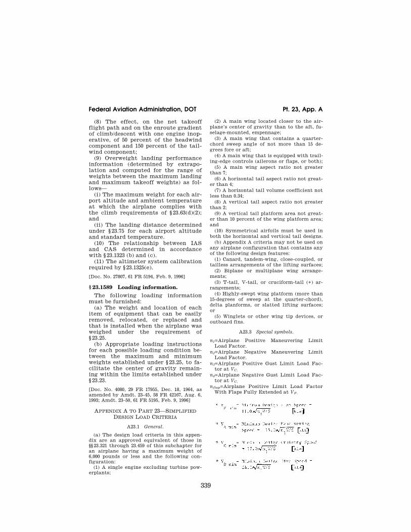
339
Federal Aviation Administration, DOT Pt. 23, App. A
(8) The effect, on the net takeoff flight path and on the enroute gradient of climb/descent with one engine inop-erative, of 50 percent of the headwind component and 150 percent of the tail-wind component;
(9) Overweight landing performance information (determined by extrapo-lation and computed for the range of weights between the maximum landing and maximum takeoff weights) as fol-lows—
(i) The maximum weight for each air-port altitude and ambient temperature at which the airplane complies with the climb requirements of § 23.63(d)(2); and
(ii) The landing distance determined under § 23.75 for each airport altitude and standard temperature.
(10) The relationship between IAS and CAS determined in accordance with § 23.1323 (b) and (c).
(11) The altimeter system calibration required by § 23.1325(e).
[Doc. No. 27807, 61 FR 5194, Feb. 9, 1996]
§ 23.1589 Loading information. The following loading information
must be furnished: (a) The weight and location of each
item of equipment that can be easily removed, relocated, or replaced and that is installed when the airplane was weighed under the requirement of § 23.25.
(b) Appropriate loading instructions for each possible loading condition be-tween the maximum and minimum weights established under § 23.25, to fa-cilitate the center of gravity remain-ing within the limits established under § 23.23.
[Doc. No. 4080, 29 FR 17955, Dec. 18, 1964, as amended by Amdt. 23–45, 58 FR 42167, Aug. 6, 1993; Amdt. 23–50, 61 FR 5195, Feb. 9, 1996]
APPENDIX A TO PART 23—SIMPLIFIED DESIGN LOAD CRITERIA
A23.1 General.
(a) The design load criteria in this appen-dix are an approved equivalent of those in §§ 23.321 through 23.459 of this subchapter for an airplane having a maximum weight of 6,000 pounds or less and the following con-figuration:
(1) A single engine excluding turbine pow-erplants;
(2) A main wing located closer to the air-plane’s center of gravity than to the aft, fu-selage-mounted, empennage;
(3) A main wing that contains a quarter- chord sweep angle of not more than 15 de-grees fore or aft;
(4) A main wing that is equipped with trail-ing-edge controls (ailerons or flaps, or both);
(5) A main wing aspect ratio not greater than 7;
(6) A horizontal tail aspect ratio not great-er than 4;
(7) A horizontal tail volume coefficient not less than 0.34;
(8) A vertical tail aspect ratio not greater than 2;
(9) A vertical tail platform area not great-er than 10 percent of the wing platform area; and
(10) Symmetrical airfoils must be used in both the horizontal and vertical tail designs.
(b) Appendix A criteria may not be used on any airplane configuration that contains any of the following design features:
(1) Canard, tandem-wing, close-coupled, or tailless arrangements of the lifting surfaces;
(2) Biplane or multiplane wing arrange-ments;
(3) T-tail, V-tail, or cruciform-tail (+) ar-rangements;
(4) Highly-swept wing platform (more than 15-degrees of sweep at the quarter-chord), delta planforms, or slatted lifting surfaces; or
(5) Winglets or other wing tip devices, or outboard fins.
A23.3 Special symbols.
n1=Airplane Positive Maneuvering Limit Load Factor.
n2=Airplane Negative Maneuvering Limit Load Factor.
n3=Airplane Positive Gust Limit Load Fac-tor at VC.
n4=Airplane Negative Gust Limit Load Fac-tor at VC.
nflap=Airplane Positive Limit Load Factor With Flaps Fully Extended at VF.
VerDate Mar<15>2010 14:10 Mar 01, 2011 Jkt 223043 PO 00000 Frm 00349 Fmt 8010 Sfmt 8002 Y:\SGML\223043.XXX 223043 EC
28S
E91
.020
</M
AT
H>
ww
oods
2 on
DS
K1D
XX
6B1P
RO
D w
ith C
FR

340
14 CFR Ch. I (1–1–11 Edition) Pt. 23, App. A
A23.5 Certification in more than one category.
The criteria in this appendix may be used for certification in the normal, utility, and acrobatic categories, or in any combination of these categories. If certification in more than one category is desired, the design cat-egory weights must be selected to make the term n1W constant for all categories or greater for one desired category than for others. The wings and control surfaces (in-cluding wing flaps and tabs) need only be in-vestigated for the maximum value of n1W, or for the category corresponding to the max-imum design weight, where n1W is constant. If the acrobatic category is selected, a spe-cial unsymmetrical flight load investigation in accordance with paragraphs A23.9(c)(2) and A23.11(c)(2) of this appendix must be completed. The wing, wing carrythrough, and the horizontal tail structures must be checked for this condition. The basic fuse-lage structure need only be investigated for the highest load factor design category se-lected. The local supporting structure for dead weight items need only be designed for the highest load factor imposed when the particular items are installed in the air-plane. The engine mount, however, must be designed for a higher side load factor, if cer-tification in the acrobatic category is de-sired, than that required for certification in the normal and utility categories. When de-signing for landing loads, the landing gear and the airplane as a whole need only be in-vestigated for the category corresponding to the maximum design weight. These sim-plifications apply to single-engine aircraft of conventional types for which experience is available, and the Administrator may re-quire additional investigations for aircraft with unusual design features.
A23.7 Flight loads.
(a) Each flight load may be considered independent of altitude and, except for the local supporting structure for dead weight items, only the maximum design weight con-ditions must be investigated.
(b) Table 1 and figures 3 and 4 of this ap-pendix must be used to determine values of n1, n2, n3, and n4, corresponding to the max-imum design weights in the desired cat-egories.
(c) Figures 1 and 2 of this appendix must be used to determine values of n3 and n4 cor-responding to the minimum flying weights in the desired categories, and, if these load fac-tors are greater than the load factors at the design weight, the supporting structure for dead weight items must be substantiated for the resulting higher load factors.
(d) Each specified wing and tail loading is independent of the center of gravity range. The applicant, however, must select a c.g. range, and the basic fuselage structure must be investigated for the most adverse dead
weight loading conditions for the c.g. range selected.
(e) The following loads and loading condi-tions are the minimums for which strength must be provided in the structure:
(1) Airplane equilibrium. The aerodynamic wing loads may be considered to act normal to the relative wind, and to have a mag-nitude of 1.05 times the airplane normal loads (as determined from paragraphs A23.9 (b) and (c) of this appendix) for the positive flight conditions and a magnitude equal to the airplane normal loads for the negative conditions. Each chordwise and normal com-ponent of this wing load must be considered.
(2) Minimum design airspeeds. The minimum design airspeeds may be chosen by the appli-cant except that they may not be less than the minimum speeds found by using figure 3 of this appendix. In addition, VCmin need not exceed values of 0.9 VH actually obtained at sea level for the lowest design weight cat-egory for which certification is desired. In computing these minimum design airspeeds, n1 may not be less than 3.8.
(3) Flight load factor. The limit flight load factors specified in Table 1 of this appendix represent the ratio of the aerodynamic force component (acting normal to the assumed longitudinal axis of the airplane) to the weight of the airplane. A positive flight load factor is an aerodynamic force acting up-ward, with respect to the airplane.
A23.9 Flight conditions.
(a) General. Each design condition in para-graphs (b) and (c) of this section must be used to assure sufficient strength for each condition of speed and load factor on or within the boundary of a V¥n diagram for the airplane similar to the diagram in figure 4 of this appendix. This diagram must also be used to determine the airplane structural op-erating limitations as specified in §§ 23.1501(c) through 23.1513 and § 23.1519.
(b) Symmetrical flight conditions. The air-plane must be designed for symmetrical flight conditions as follows:
(1) The airplane must be designed for at least the four basic flight conditions, ‘‘A’’, ‘‘D’’, ‘‘E’’, and ‘‘G’’ as noted on the flight enve-lope of figure 4 of this appendix. In addition, the following requirements apply:
(i) The design limit flight load factors cor-responding to conditions ‘‘D’’ and ‘‘E’’ of figure 4 must be at least as great as those specified in Table 1 and figure 4 of this appendix, and the design speed for these conditions must be at least equal to the value of VD found from figure 3 of this appendix.
(ii) For conditions ‘‘A’’ and ‘‘G’’ of figure 4, the load factors must correspond to those specified in Table 1 of this appendix, and the design speeds must be computed using these load factors with the maximum static lift coefficient CNA determined by the applicant. However, in the absence of more precise
VerDate Mar<15>2010 14:10 Mar 01, 2011 Jkt 223043 PO 00000 Frm 00350 Fmt 8010 Sfmt 8002 Y:\SGML\223043.XXX 223043ww
oods
2 on
DS
K1D
XX
6B1P
RO
D w
ith C
FR

341
Federal Aviation Administration, DOT Pt. 23, App. A
computations, these latter conditions may be based on a value of CNA=±1.35 and the de-sign speed for condition ‘‘A’’ may be less than VAmin.
(iii) Conditions ‘‘C’’ and ‘‘F’’ of figure 4 need only be investigated when n3 W/S or n4 W/S are greater than n1 W/S or n2 W/S of this ap-pendix, respectively.
(2) If flaps or other high lift devices in-tended for use at the relatively low airspeed of approach, landing, and takeoff, are in-stalled, the airplane must be designed for the two flight conditions corresponding to the values of limit flap-down factors specified in Table 1 of this appendix with the flaps fully extended at not less than the design flap speed VFmin from figure 3 of this appendix.
(c) Unsymmetrical flight conditions. Each af-fected structure must be designed for unsym-metrical loadings as follows:
(1) The aft fuselage-to-wing attachment must be designed for the critical vertical surface load determined in accordance with paragraph SA23.11(c)(1) and (2) of this appen-dix.
(2) The wing and wing carry-through struc-tures must be designed for 100 percent of con-dition ‘‘A’’ loading on one side of the plane of symmetry and 70 percent on the opposite side for certification in the normal and util-ity categories, or 60 percent on the opposite side for certification in the acrobatic cat-egory.
(3) The wing and wing carry-through struc-tures must be designed for the loads result-ing from a combination of 75 percent of the positive maneuvering wing loading on both sides of the plane of symmetry and the max-imum wing torsion resulting from aileron displacement. The effect of aileron displace-ment on wing torsion at VC or VA using the basic airfoil moment coefficient modified over the aileron portion of the span, must be computed as follows:
(i) Cm=Cm +0.01dm (up aileron side) wing basic airfoil.
(ii) Cm=Cm ¥0.01dm(down aileron side) wing basic airfoil, where dm is the up aileron de-flection and d d is the down aileron deflec-tion.
(4) D critical, which is the sum of dm+d d must be computed as follows:
(i) Compute Da and DB from the formulas:
Δ Δ
Δ Δ
aA
C
p
bA
D
p
V
V
V
V
= ×
= ×
and
0 5.
Where DP=the maximum total deflection (sum of both aileron deflections) at VA with VA, VC, and VD described in subpara-graph (2) of § 23.7(e) of this appendix.
(ii) Compute K from the formula:
KC V
C V
m b D
m a C
=−( )−( )
0 01
0 01
2
2
.
.
δ
δwhere da is the down aileron deflection cor-
responding to Da, and db is the down aile-ron deflection corresponding to D b as com-puted in step (i). (iii) If K is less than 1.0, Da is D critical and
must be used to determine dU and dd. In this case, VC is the critical speed which must be used in computing the wing torsion loads over the aileron span.
(iv) If K is equal to or greater than 1.0, DB is D critical and must be used to determine dU and dD. In this case, Vd is the critical speed which must be used in computing the wing torsion loads over the aileron span.
(d) Supplementary conditions; rear lift truss; engine torque; side load on engine mount. Each of the following supplementary conditions must be investigated:
(1) In designing the rear lift truss, the spe-cial condition specified in § 23.369 may be in-vestigated instead of condition ‘‘G’’ of figure 4 of this appendix. If this is done, and if cer-tification in more than one category is de-sired, the value of W/S used in the formula appearing in § 23.369 must be that for the cat-egory corresponding to the maximum gross weight.
(2) Each engine mount and its supporting structures must be designed for the max-imum limit torque corresponding to METO power and propeller speed acting simulta-neously with the limit loads resulting from the maximum positive maneuvering flight load factor n1. The limit torque must be ob-tained by multiplying the mean torque by a factor of 1.33 for engines with five or more cylinders. For 4, 3, and 2 cylinder engines, the factor must be 2, 3, and 4, respectively.
(3) Each engine mount and its supporting structure must be designed for the loads re-sulting from a lateral limit load factor of not less than 1.47 for the normal and utility cat-egories, or 2.0 for the acrobatic category.
A23.11 Control surface loads.
(a) General. Each control surface load must be determined using the criteria of para-graph (b) of this section and must lie within the simplified loadings of paragraph (c) of this section.
(b) Limit pilot forces. In each control surface loading condition described in paragraphs (c) through (e) of this section, the airloads on the movable surfaces and the corresponding deflections need not exceed those which could be obtained in flight by employing the maximum limit pilot forces specified in the table in § 23.397(b). If the surface loads are limited by these maximum limit pilot forces,
VerDate Mar<15>2010 14:10 Mar 01, 2011 Jkt 223043 PO 00000 Frm 00351 Fmt 8010 Sfmt 8002 Y:\SGML\223043.XXX 223043 EC
28S
E91
.021
</M
AT
H>
EC
28S
E91
.022
</M
AT
H>
ww
oods
2 on
DS
K1D
XX
6B1P
RO
D w
ith C
FR

342
14 CFR Ch. I (1–1–11 Edition) Pt. 23, App. A
the tabs must either be considered to be de-flected to their maximum travel in the direc-tion which would assist the pilot or the de-flection must correspond to the maximum degree of ‘‘out of trim’’ expected at the speed for the condition under consideration. The tab load, however, need not exceed the value specified in Table 2 of this appendix.
(c) Surface loading conditions. Each surface loading condition must be investigated as follows:
(1) Simplified limit surface loadings for the horizontal tail, vertical tail, aileron, wing flaps, and trim tabs are specified in figures 5 and 6 of this appendix.
(i) The distribution of load along the span of the surface, irrespective of the chordwise load distribution, must be assumed propor-tional to the total chord, except on horn bal-ance surfaces.
(ii) The load on the stabilizer and elevator, and the load on fin and rudder, must be dis-tributed chordwise as shown in figure 7 of this appendix.
(iii) In order to ensure adequate torsional strength and to account for maneuvers and
gusts, the most severe loads must be consid-ered in association with every center of pres-sure position between the leading edge and the half chord of the mean chord of the sur-face (stabilizer and elevator, or fin and rud-der).
(iv) To ensure adequate strength under high leading edge loads, the most severe sta-bilizer and fin loads must be further consid-ered as being increased by 50 percent over the leading 10 percent of the chord with the loads aft of this appropriately decreased to retain the same total load.
(v) The most severe elevator and rudder loads should be further considered as being distributed parabolically from three times the mean loading of the surface (stabilizer and elevator, or fin and rudder) at the lead-ing edge of the elevator and rudder, respec-tively, to zero at the trailing edge according to the equation:
P x wc x
cf
( ) ( )( )
=−
32
2
Where—
P(x)=local pressure at the chordwise stations x,
c=chord length of the tail surface, cf=chord length of the elevator and rudder
respectively, and w̆≤=average surface loading as specified in
Figure A5.
(vi) The chordwise loading distribution for ailerons, wing flaps, and trim tabs are speci-fied in Table 2 of this appendix.
(2) If certification in the acrobatic cat-egory is desired, the horizontal tail must be investigated for an unsymmetrical load of 100 percent w on one side of the airplane cen-terline and 50 percent on the other side of the airplane centerline.
(d) Outboard fins. Outboard fins must meet the requirements of § 23.445.
VerDate Mar<15>2010 14:10 Mar 01, 2011 Jkt 223043 PO 00000 Frm 00352 Fmt 8010 Sfmt 8002 Y:\SGML\223043.XXX 223043 ER
09F
E96
.004
</M
AT
H>
ER
09F
E96
.007
</G
PH
>
ww
oods
2 on
DS
K1D
XX
6B1P
RO
D w
ith C
FR
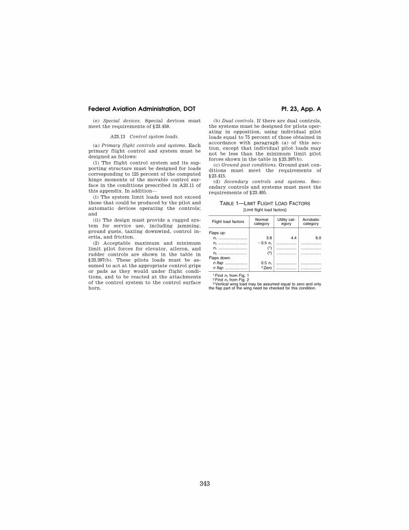
343
Federal Aviation Administration, DOT Pt. 23, App. A
(e) Special devices. Special devices must meet the requirements of § 23.459.
A23.13 Control system loads.
(a) Primary flight controls and systems. Each primary flight control and system must be designed as follows:
(1) The flight control system and its sup-porting structure must be designed for loads corresponding to 125 percent of the computed hinge moments of the movable control sur-face in the conditions prescribed in A23.11 of this appendix. In addition—
(i) The system limit loads need not exceed those that could be produced by the pilot and automatic devices operating the controls; and
(ii) The design must provide a rugged sys-tem for service use, including jamming, ground gusts, taxiing downwind, control in-ertia, and friction.
(2) Acceptable maximum and minimum limit pilot forces for elevator, aileron, and rudder controls are shown in the table in § 23.397(b). These pilots loads must be as-sumed to act at the appropriate control grips or pads as they would under flight condi-tions, and to be reacted at the attachments of the control system to the control surface horn.
(b) Dual controls. If there are dual controls, the systems must be designed for pilots oper-ating in opposition, using individual pilot loads equal to 75 percent of those obtained in accordance with paragraph (a) of this sec-tion, except that individual pilot loads may not be less than the minimum limit pilot forces shown in the table in § 23.397(b).
(c) Ground gust conditions. Ground gust con-ditions must meet the requirements of § 23.415.
(d) Secondary controls and systems. Sec-ondary controls and systems must meet the requirements of § 23.405.
TABLE 1—LIMIT FLIGHT LOAD FACTORS [Limit flight load factors]
Flight load factors Normal category
Utility cat-egory
Acrobatic category
Flaps up: n1 .......................... 3.8 4.4 6.0 n2 .......................... ¥0.5 n1 .................. ..................n3 .......................... (1) .................. ..................n4 .......................... (2) .................. ..................
Flaps down: n flap .................... 0.5 n1 .................. ..................n flap .................... 3 Zero .................. ..................
1 Find n3 from Fig. 1 2 Find n4 from Fig. 2 3 Vertical wing load may be assumed equal to zero and only
the flap part of the wing need be checked for this condition.
VerDate Mar<15>2010 14:10 Mar 01, 2011 Jkt 223043 PO 00000 Frm 00353 Fmt 8010 Sfmt 8002 Y:\SGML\223043.XXX 223043ww
oods
2 on
DS
K1D
XX
6B1P
RO
D w
ith C
FR
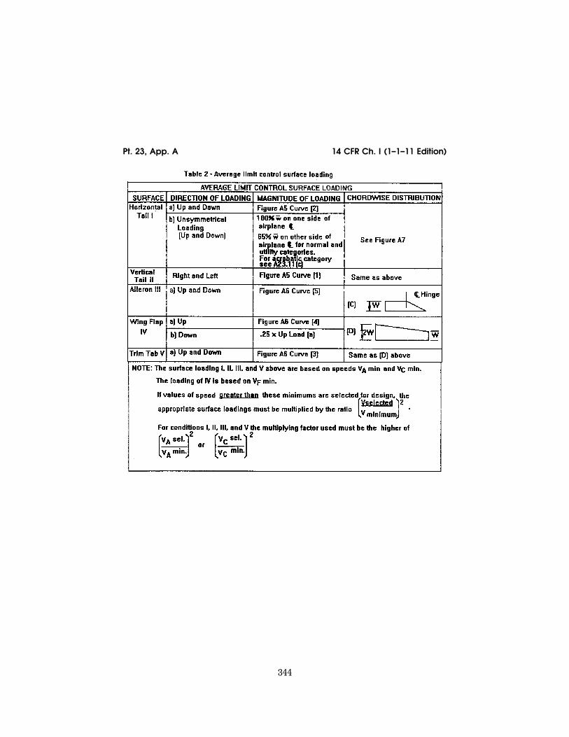
344
14 CFR Ch. I (1–1–11 Edition) Pt. 23, App. A
VerDate Mar<15>2010 14:10 Mar 01, 2011 Jkt 223043 PO 00000 Frm 00354 Fmt 8010 Sfmt 8006 Y:\SGML\223043.XXX 223043 ER
09F
E96
.008
</G
PH
>
ww
oods
2 on
DS
K1D
XX
6B1P
RO
D w
ith C
FR

345
Federal Aviation Administration, DOT Pt. 23, App. A
VerDate Mar<15>2010 14:10 Mar 01, 2011 Jkt 223043 PO 00000 Frm 00355 Fmt 8010 Sfmt 8006 Y:\SGML\223043.XXX 223043 EC
28S
E91
.023
</G
PH
>
ww
oods
2 on
DS
K1D
XX
6B1P
RO
D w
ith C
FR

346
14 CFR Ch. I (1–1–11 Edition) Pt. 23, App. A
VerDate Mar<15>2010 14:10 Mar 01, 2011 Jkt 223043 PO 00000 Frm 00356 Fmt 8010 Sfmt 8006 Y:\SGML\223043.XXX 223043 EC
28S
E91
.024
</G
PH
>
ww
oods
2 on
DS
K1D
XX
6B1P
RO
D w
ith C
FR
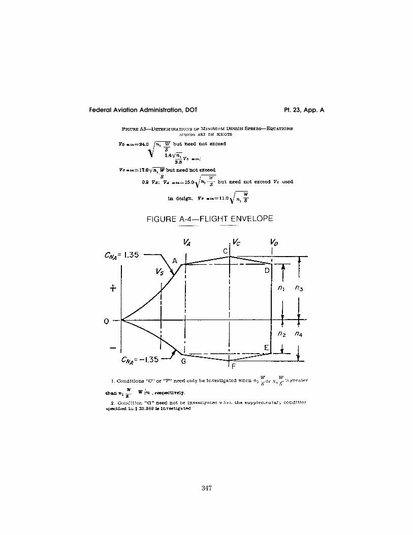
347
Federal Aviation Administration, DOT Pt. 23, App. A
VerDate Mar<15>2010 14:10 Mar 01, 2011 Jkt 223043 PO 00000 Frm 00357 Fmt 8010 Sfmt 8006 Y:\SGML\223043.XXX 223043 EC
28S
E91
.025
</G
PH
>E
C28
SE
91.0
26<
/GP
H>
ww
oods
2 on
DS
K1D
XX
6B1P
RO
D w
ith C
FR
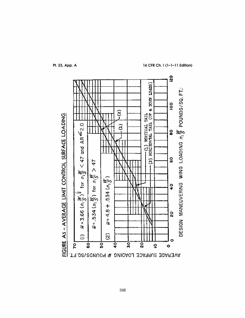
348
14 CFR Ch. I (1–1–11 Edition) Pt. 23, App. A
VerDate Mar<15>2010 14:10 Mar 01, 2011 Jkt 223043 PO 00000 Frm 00358 Fmt 8010 Sfmt 8006 Y:\SGML\223043.XXX 223043 EC
28S
E91
.027
</G
PH
>
ww
oods
2 on
DS
K1D
XX
6B1P
RO
D w
ith C
FR
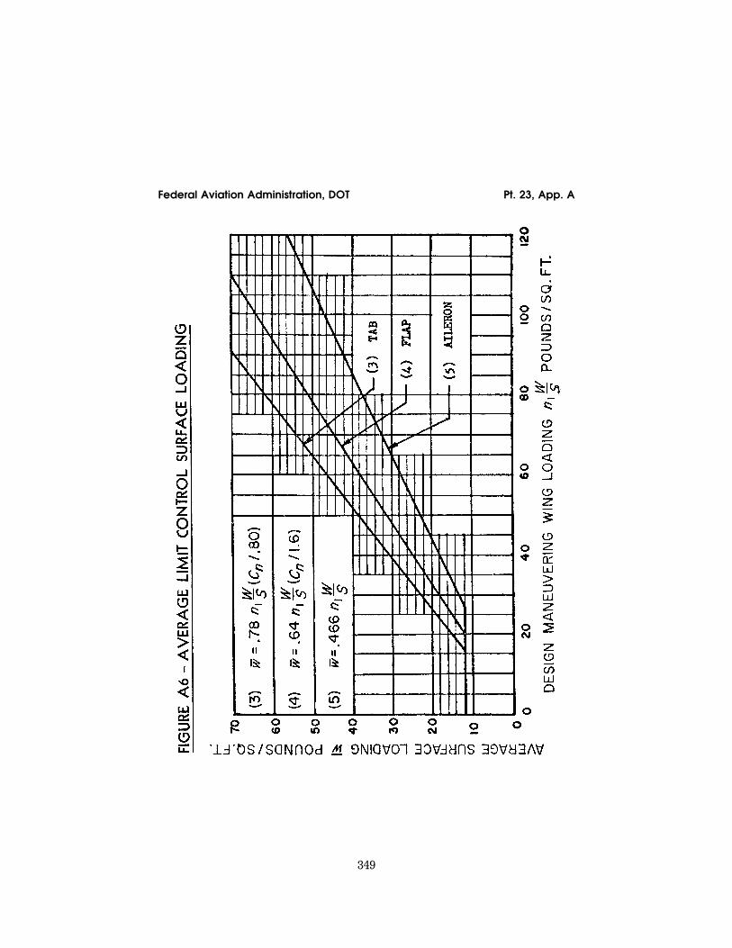
349
Federal Aviation Administration, DOT Pt. 23, App. A
VerDate Mar<15>2010 14:10 Mar 01, 2011 Jkt 223043 PO 00000 Frm 00359 Fmt 8010 Sfmt 8006 Y:\SGML\223043.XXX 223043 EC
28S
E91
.028
</G
PH
>
ww
oods
2 on
DS
K1D
XX
6B1P
RO
D w
ith C
FR
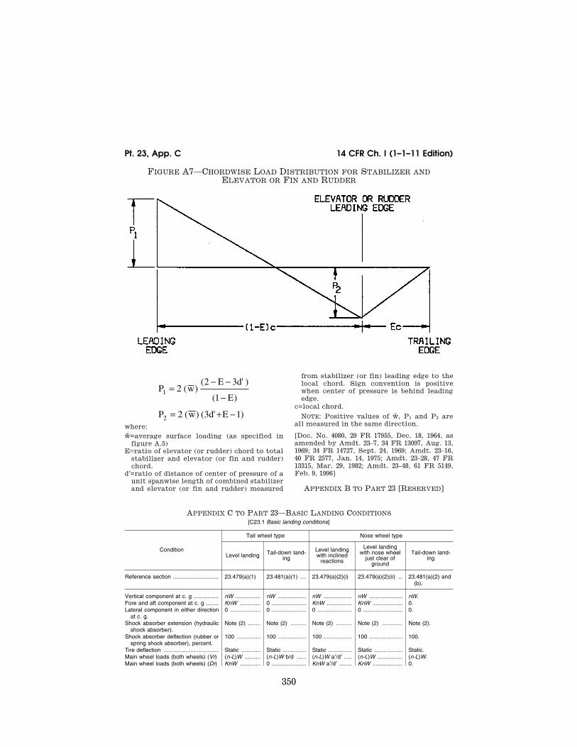
350
14 CFR Ch. I (1–1–11 Edition) Pt. 23, App. C
FIGURE A7—CHORDWISE LOAD DISTRIBUTION FOR STABILIZER AND ELEVATOR OR FIN AND RUDDER
P wE d
E
P w d E
1
2
22 3
1
2 3 1
=− −
−
= + −
( )( ' )
( )
( ) ( ' )where: w̄=average surface loading (as specified in
figure A.5) E=ratio of elevator (or rudder) chord to total
stabilizer and elevator (or fin and rudder) chord.
d′=ratio of distance of center of pressure of a unit spanwise length of combined stabilizer and elevator (or fin and rudder) measured
from stabilizer (or fin) leading edge to the local chord. Sign convention is positive when center of pressure is behind leading edge.
c=local chord.
NOTE: Positive values of w̄, P1 and P2 are all measured in the same direction.
[Doc. No. 4080, 29 FR 17955, Dec. 18, 1964, as amended by Amdt. 23–7, 34 FR 13097, Aug. 13, 1969; 34 FR 14727, Sept. 24, 1969; Amdt. 23–16, 40 FR 2577, Jan. 14, 1975; Amdt. 23–28, 47 FR 13315, Mar. 29, 1982; Amdt. 23–48, 61 FR 5149, Feb. 9, 1996]
APPENDIX B TO PART 23 [RESERVED]
APPENDIX C TO PART 23—BASIC LANDING CONDITIONS [C23.1 Basic landing conditions]
Condition
Tail wheel type Nose wheel type
Level landing Tail-down land-ing
Level landing with inclined
reactions
Level landing with nose wheel
just clear of ground
Tail-down land-ing
Reference section ............................. 23.479(a)(1) 23.481(a)(1) .... 23.479(a)(2)(i) 23.479(a)(2)(ii) ... 23.481(a)(2) and (b).
Vertical component at c. g ................ nW ................ nW .................. nW .................. nW ..................... nW. Fore and aft component at c. g ........ KnW ............. 0 ...................... KnW ................ KnW ................... 0. Lateral component in either direction
at c. g.0 ................... 0 ...................... 0 ...................... 0 ......................... 0.
Shock absorber extension (hydraulic shock absorber).
Note (2) ........ Note (2) .......... Note (2) .......... Note (2) ............. Note (2).
Shock absorber deflection (rubber or spring shock absorber), percent.
100 ............... 100 .................. 100 .................. 100 ..................... 100.
Tire deflection ................................... Static ............ Static ............... Static ............... Static .................. Static. Main wheel loads (both wheels) (Vr) (n-L)W .......... (n-L)W b/d ...... (n-L)W a′/d′ ..... (n-L)W ................ (n-L)W. Main wheel loads (both wheels) (Dr) KnW ............. 0 ...................... KnW a′/d′ ........ KnW ................... 0.
VerDate Mar<15>2010 14:10 Mar 01, 2011 Jkt 223043 PO 00000 Frm 00360 Fmt 8010 Sfmt 8002 Y:\SGML\223043.XXX 223043 ER
09F
E96
.009
</G
PH
>E
R09
FE
96.0
05<
/GP
H>
ww
oods
2 on
DS
K1D
XX
6B1P
RO
D w
ith C
FR

351
Federal Aviation Administration, DOT Pt. 23, App. D
[C23.1 Basic landing conditions]
Condition
Tail wheel type Nose wheel type
Level landing Tail-down land-ing
Level landing with inclined
reactions
Level landing with nose wheel
just clear of ground
Tail-down land-ing
Tail (nose) wheel loads (Vf) ............. 0 ................... (n-L)W a/d ...... (n-L)W b′/d′ ..... 0 ......................... 0. Tail (nose) wheel loads (Df) ............. 0 ................... 0 ...................... KnW b′/d′ ........ 0 ......................... 0. Notes ................................................. (1), (3), and
(4).(4) ................... (1) ................... (1), (3), and (4) .. (3) and (4).
NOTE (1). K may be determined as follows: K=0.25 for W=3,000 pounds or less; K=0.33 for W=6,000 pounds or greater, with linear variation of K between these weights.
NOTE (2). For the purpose of design, the maximum load factor is assumed to occur throughout the shock absorber stroke from 25 percent deflection to 100 percent deflection unless otherwise shown and the load factor must be used with whatever shock absorber extension is most critical for each element of the landing gear.
NOTE (3). Unbalanced moments must be balanced by a rational or conservative method. NOTE (4). L is defined in § 23.735(b). NOTE (5). n is the limit inertia load factor, at the c.g. of the airplane, selected under § 23.473 (d), (f), and (g).
[Doc. No. 4080, 29 FR 17955, Dec. 18, 1964, as amended by Amdt. 23–7, 34 FR 13099, Aug. 13, 1969]
APPENDIX D TO PART 23—WHEEL SPIN- UP AND SPRING-BACK LOADS
D23.1 Wheel spin-up loads. (a) The following method for determining
wheel spin-up loads for landing conditions is based on NACA T.N. 863. However, the drag component used for design may not be less than the drag load prescribed in § 23.479(b).
FHmax=1/re √ 2Iw(VH—Vc)nFVmax/tS where—
FHmax=maximum rearward horizontal force acting on the wheel (in pounds);
re=effective rolling radius of wheel under im-pact based on recommended operating tire pressure (which may be assumed to be equal to the rolling radius under a static load of njWe) in feet;
VerDate Mar<15>2010 14:10 Mar 01, 2011 Jkt 223043 PO 00000 Frm 00361 Fmt 8010 Sfmt 8002 Y:\SGML\223043.XXX 223043 EC
28S
E91
.029
</G
PH
>
ww
oods
2 on
DS
K1D
XX
6B1P
RO
D w
ith C
FR
352
14 CFR Ch. I (1–1–11 Edition) Pt. 23, App. F
Iw=rotational mass moment of inertia of rolling assembly (in slug feet);
VH=linear velocity of airplane parallel to ground at instant of contact (assumed to be 1.2 VS0, in feet per second);
Vc=peripheral speed of tire, if prerotation is used (in feet per second) (there must be a positive means of pre-rotation before pre- rotation may be considered);
n=equals effective coefficient of friction (0.80 may be used);
FVmax=maximum vertical force on wheel (pounds)=njWe, where We and nj are defined in § 23.725;
ts=time interval between ground contact and attainment of maximum vertical force on wheel (seconds). (However, if the value of FVmax, from the above equation exceeds 0.8 FVmax, the latter value must be used for FHmax.)
(b) The equation assumes a linear vari-ation of load factor with time until the peak load is reached and under this assumption, the equation determines the drag force at the time that the wheel peripheral velocity at radius re equals the airplane velocity. Most shock absorbers do not exactly follow a linear variation of load factor with time. Therefore, rational or conservative allow-ances must be made to compensate for these variations. On most landing gears, the time for wheel spin-up will be less than the time required to develop maximum vertical load factor for the specified rate of descent and forward velocity. For exceptionally large wheels, a wheel peripheral velocity equal to the ground speed may not have been attained at the time of maximum vertical gear load. However, as stated above, the drag spin-up load need not exceed 0.8 of the maximum vertical loads.
(c) Dynamic spring-back of the landing gear and adjacent structure at the instant just after the wheels come up to speed may result in dynamic forward acting loads of considerable magnitude. This effect must be determined, in the level landing condition, by assuming that the wheel spin-up loads calculated by the methods of this appendix are reversed. Dynamic spring-back is likely to become critical for landing gear units having wheels of large mass or high landing speeds.
[Doc. No. 4080, 29 FR 17955, Dec. 18, 1964, as amended by Amdt. 23–45, 58 FR 42167, Aug. 6, 1993]
APPENDIX E TO PART 23 [RESERVED]
APPENDIX F TO PART 23—TEST PROCEDURE
Acceptable test procedure for self-extin-guishing materials for showing compliance with §§ 23.853, 23.855 and 23.1359.
(a) Conditioning. Specimens must be condi-tioned to 70 degrees F, plus or minus 5 de-grees, and at 50 percent plus or minus 5 per-cent relative humidity until moisture equi-librium is reached or for 24 hours. Only one specimen at a time may be removed from the conditioning environment immediately be-fore subjecting it to the flame.
(b) Specimen configuration. Except as pro-vided for materials used in electrical wire and cable insulation and in small parts, ma-terials must be tested either as a section cut from a fabricated part as installed in the air-plane or as a specimen simulating a cut sec-tion, such as: a specimen cut from a flat sheet of the material or a model of the fab-ricated part. The specimen may be cut from any location in a fabricated part; however, fabricated units, such as sandwich panels, may not be separated for a test. The speci-men thickness must be no thicker than the minimum thickness to be qualified for use in the airplane, except that: (1) Thick foam parts, such as seat cushions, must be tested in 1⁄2 inch thickness; (2) when showing com-pliance with § 23.853(d)(3)(v) for materials used in small parts that must be tested, the materials must be tested in no more than 1⁄8 inch thickness; (3) when showing compliance with § 23.1359(c) for materials used in elec-trical wire and cable insulation, the wire and cable specimens must be the same size as used in the airplane. In the case of fabrics, both the warp and fill direction of the weave must be tested to determine the most crit-ical flammability conditions. When per-forming the tests prescribed in paragraphs (d) and (e) of this appendix, the specimen must be mounted in a metal frame so that (1) in the vertical tests of paragraph (d) of this appendix, the two long edges and the upper edge are held securely; (2) in the horizontal test of paragraph (e) of this appendix, the two long edges and the edge away from the flame are held securely; (3) the exposed area of the specimen is at least 2 inches wide and 12 inches long, unless the actual size used in the airplane is smaller; and (4) the edge to which the burner flame is applied must not consist of the finished or protected edge of the specimen but must be representative of the actual cross section of the material or part installed in the airplane. When per-forming the test prescribed in paragraph (f) of this appendix, the specimen must be mounted in metal frame so that all four edges are held securely and the exposed area of the specimen is at least 8 inches by 8 inches.
(c) Apparatus. Except as provided in para-graph (g) of this appendix, tests must be con-ducted in a draft-free cabinet in accordance with Federal Test Method Standard 191 Method 5903 (revised Method 5902) which is available from the General Services Admin-istration, Business Service Center, Region 3, Seventh and D Streets SW., Washington,
VerDate Mar<15>2010 14:10 Mar 01, 2011 Jkt 223043 PO 00000 Frm 00362 Fmt 8010 Sfmt 8002 Y:\SGML\223043.XXX 223043ww
oods
2 on
DS
K1D
XX
6B1P
RO
D w
ith C
FR

353
Federal Aviation Administration, DOT Pt. 23, App. F
D.C. 20407, or with some other approved equivalent method. Specimens which are too large for the cabinet must be tested in simi-lar draft-free conditions.
(d) Vertical test. A minimum of three speci-mens must be tested and the results aver-aged. For fabrics, the direction of weave cor-responding to the most critical flammability conditions must be parallel to the longest di-mension. Each specimen must be supported vertically. The specimen must be exposed to a Bunsen or Tirrill burner with a nominal 3⁄8- inch I.D. tube adjusted to give a flame of 11⁄2 inches in height. The minimum flame tem-perature measured by a calibrated thermo-couple pryometer in the center of the flame must be 1550 °F. The lower edge of the speci-men must be three-fourths inch above the top edge of the burner. The flame must be applied to the center line of the lower edge of the specimen. For materials covered by §§ 23.853(d)(3)(i) and 23.853(f), the flame must be applied for 60 seconds and then removed. For materials covered by § 23.853(d)(3)(ii), the flame must be applied for 12 seconds and then removed. Flame time, burn length, and flaming time of drippings, if any, must be re-corded. The burn length determined in ac-cordance with paragraph (h) of this appendix must be measured to the nearest one-tenth inch.
(e) Horizontal test. A minimum of three specimens must be tested and the results averaged. Each specimen must be supported horizontally. The exposed surface when in-stalled in the airplane must be face down for the test. The specimen must be exposed to a Bunsen burner or Tirrill burner with a nomi-nal 3⁄8-inch I.D. tube adjusted to give a flame of 11⁄2 inches in height. The minimum flame temperature measured by a calibrated ther-mocouple pyrometer in the center of the flame must be 1550 °F. The specimen must be positioned so that the edge being tested is three-fourths of an inch above the top of, and on the center line of, the burner. The flame must be applied for 15 seconds and then re-moved. A minimum of 10 inches of the speci-men must be used for timing purposes, ap-proximately 11⁄2 inches must burn before the burning front reaches the timing zone, and the average burn rate must be recorded.
(f) Forty-five degree test. A minimum of three specimens must be tested and the re-sults averaged. The specimens must be sup-ported at an angle of 45 degrees to a hori-zontal surface. The exposed surface when in-stalled in the aircraft must be face down for the test. The specimens must be exposed to a Bunsen or Tirrill burner with a nominal 3⁄8 inch I.D. tube adjusted to give a flame of 11⁄2 inches in height. The minimum flame tem-perature measured by a calibrated thermo-couple pyrometer in the center of the flame must be 1550 °F. Suitable precautions must be taken to avoid drafts. The flame must be applied for 30 seconds with one-third con-
tacting the material at the center of the specimen and then removed. Flame time, glow time, and whether the flame penetrates (passes through) the specimen must be re-corded.
(g) Sixty-degree test. A minimum of three specimens of each wire specification (make and size) must be tested. The specimen of wire or cable (including insulation) must be placed at an angle of 60 degrees with the hor-izontal in the cabinet specified in paragraph (c) of this appendix, with the cabinet door open during the test or placed within a chamber approximately 2 feet high × 1 foot × 1 foot, open at the top and at one vertical side (front), that allows sufficient flow of air for complete combustion but is free from drafts. The specimen must be parallel to and approximately 6 inches from the front of the chamber. The lower end of the specimen must be held rigidly clamped. The upper end of the specimen must pass over a pulley or rod and must have an appropriate weight at-tached to it so that the specimen is held tautly throughout the flammability test. The test specimen span between lower clamp and upper pulley or rod must be 24 inches and must be marked 8 inches from the lower end to indicate the central point for flame application. A flame from a Bunsen or Tirrill burner must be applied for 30 seconds at the test mark. The burner must be mounted un-derneath the test mark on the specimen, per-pendicular to the specimen and at an angle of 30 degrees to the vertical plane of the specimen. The burner must have a nominal bore of three-eighths inch, and must be ad-justed to provide a three-inch-high flame with an inner cone approximately one-third of the flame height. The minimum tempera-ture of the hottest portion of the flame, as measured with a calibrated thermocouple pyrometer, may not be less than 1,750 °F. The burner must be positioned so that the hot-test portion of the flame is applied to the test mark on the wire. Flame time, burn length, and flaming time drippings, if any, must be recorded. The burn length deter-mined in accordance with paragraph (h) of this appendix must be measured to the near-est one-tenth inch. Breaking of the wire specimen is not considered a failure.
(h) Burn length. Burn length is the distance from the original edge to the farthest evi-dence of damage to the test specimen due to flame impingement, including areas of par-tial or complete consumption, charring, or embrittlement, but not including areas soot-ed, stained, warped, or discolored, nor areas where material has shrunk or melted away from the heat source.
[Amdt. 23–23, 43 FR 50594, Oct. 30, 1978, as amended by Amdt. 23–34, 52 FR 1835, Jan. 15, 1987; 52 FR 34745, Sept. 14, 1987; Amdt. 23–49, 61 FR 5170, Feb. 9, 1996]
VerDate Mar<15>2010 14:10 Mar 01, 2011 Jkt 223043 PO 00000 Frm 00363 Fmt 8010 Sfmt 8002 Y:\SGML\223043.XXX 223043ww
oods
2 on
DS
K1D
XX
6B1P
RO
D w
ith C
FR

354
14 CFR Ch. I (1–1–11 Edition) Pt. 23, App. G
APPENDIX G TO PART 23—INSTRUCTIONS FOR CONTINUED AIRWORTHINESS
G23.1 General. (a) This appendix specifies requirements for the preparation of Instruc-tions for Continued Airworthiness as re-quired by § 23.1529.
(b) The Instructions for Continued Air-worthiness for each airplane must include the Instructions for Continued Airworthiness for each engine and propeller (hereinafter designated ‘products’), for each appliance re-quired by this chapter, and any required in-formation relating to the interface of those appliances and products with the airplane. If Instructions for Continued Airworthiness are not supplied by the manufacturer of an ap-pliance or product installed in the airplane, the Instructions for Continued Airworthiness for the airplane must include the informa-tion essential to the continued airworthiness of the airplane.
(c) The applicant must submit to the FAA a program to show how changes to the In-structions for Continued Airworthiness made by the applicant or by the manufacturers of products and appliances installed in the air-plane will be distributed.
G23.2 Format. (a) The Instructions for Continued Airworthiness must be in the form of a manual or manuals as appropriate for the quantity of data to be provided.
(b) The format of the manual or manuals must provide for a practical arrangement.
G23.3 Content. The contents of the manual or manuals must be prepared in the English language. The Instructions for Continued Airworthiness must contain the following manuals or sections, as appropriate, and in-formation:
(a) Airplane maintenance manual or section. (1) Introduction information that includes an explanation of the airplane’s features and data to the extent necessary for mainte-nance or preventive maintenance.
(2) A description of the airplane and its systems and installations including its en-gines, propellers, and appliances.
(3) Basic control and operation information describing how the airplane components and systems are controlled and how they oper-ate, including any special procedures and limitations that apply.
(4) Servicing information that covers de-tails regarding servicing points, capacities of tanks, reservoirs, types of fluids to be used, pressures applicable to the various systems, location of access panels for inspection and servicing, locations of lubrication points, lu-bricants to be used, equipment required for servicing, tow instructions and limitations, mooring, jacking, and leveling information.
(b) Maintenance instructions. (1) Scheduling information for each part of the airplane and its engines, auxiliary power units, propellers, accessories, instruments, and equipment that provides the recommended periods at
which they should be cleaned, inspected, ad-justed, tested, and lubricated, and the degree of inspection, the applicable wear tolerances, and work recommended at these periods. However, the applicant may refer to an ac-cessory, instrument, or equipment manufac-turer as the source of this information if the applicant shows that the item has an excep-tionally high degree of complexity requiring specialized maintenance techniques, test equipment, or expertise. The recommended overhaul periods and necessary cross ref-erence to the Airworthiness Limitations sec-tion of the manual must also be included. In addition, the applicant must include an in-spection program that includes the fre-quency and extent of the inspections nec-essary to provide for the continued air-worthiness of the airplane.
(2) Troubleshooting information describing probable malfunctions, how to recognize those malfunctions, and the remedial action for those malfunctions.
(3) Information describing the order and method of removing and replacing products and parts with any necessary precautions to be taken.
(4) Other general procedural instructions including procedures for system testing dur-ing ground running, symmetry checks, weighing and determining the center of grav-ity, lifting and shoring, and storage limita-tions.
(c) Diagrams of structural access plates and information needed to gain access for in-spections when access plates are not pro-vided.
(d) Details for the application of special in-spection techniques including radiographic and ultrasonic testing where such processes are specified.
(e) Information needed to apply protective treatments to the structure after inspection.
(f) All data relative to structural fasteners such as identification, discard recommenda-tions, and torque values.
(g) A list of special tools needed. (h) In addition, for commuter category air-
planes, the following information must be furnished:
(1) Electrical loads applicable to the var-ious systems;
(2) Methods of balancing control surfaces; (3) Identification of primary and secondary
structures; and (4) Special repair methods applicable to
the airplane. G23.4 Airworthiness Limitations section. The
Instructions for Continued Airworthiness must contain a section titled Airworthiness Limitations that is segregated and clearly
VerDate Mar<15>2010 14:10 Mar 01, 2011 Jkt 223043 PO 00000 Frm 00364 Fmt 8010 Sfmt 8002 Y:\SGML\223043.XXX 223043ww
oods
2 on
DS
K1D
XX
6B1P
RO
D w
ith C
FR
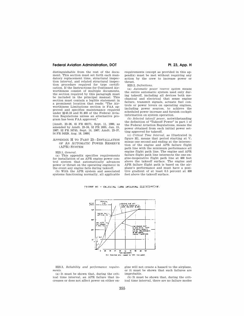
355
Federal Aviation Administration, DOT Pt. 23, App. H
distinguishable from the rest of the docu-ment. This section must set forth each man-datory replacement time, structural inspec-tion interval, and related structural inspec-tion procedure required for type certifi-cation. If the Instructions for Continued Air-worthiness consist of multiple documents, the section required by this paragraph must be included in the principal manual. This section must contain a legible statement in a prominent location that reads: ‘‘The Air-worthiness Limitations section is FAA ap-proved and specifies maintenance required under §§ 43.16 and 91.403 of the Federal Avia-tion Regulations unless an alternative pro-gram has been FAA approved.’’
[Amdt. 23–26, 45 FR 60171, Sept. 11, 1980, as amended by Amdt. 23–34, 52 FR 1835, Jan. 15, 1987; 52 FR 34745, Sept. 14, 1987; Amdt. 23–37, 54 FR 34329, Aug. 18, 1989]
APPENDIX H TO PART 23—INSTALLATION OF AN AUTOMATIC POWER RESERVE (APR) SYSTEM
H23.1, General. (a) This appendix specifies requirements
for installation of an APR engine power con-trol system that automatically advances power or thrust on the operating engine(s) in the event any engine fails during takeoff.
(b) With the APR system and associated systems functioning normally, all applicable
requirements (except as provided in this ap-pendix) must be met without requiring any action by the crew to increase power or thrust.
H23.2, Definitions. (a) Automatic power reserve system means
the entire automatic system used only dur-ing takeoff, including all devices both me-chanical and electrical that sense engine failure, transmit signals, actuate fuel con-trols or power levers on operating engines, including power sources, to achieve the scheduled power increase and furnish cockpit information on system operation.
(b) Selected takeoff power, notwithstanding the definition of ‘‘Takeoff Power’’ in part 1 of the Federal Aviation Regulations, means the power obtained from each initial power set-ting approved for takeoff.
(c) Critical Time Interval, as illustrated in figure H1, means that period starting at V1 minus one second and ending at the intersec-tion of the engine and APR failure flight path line with the minimum performance all engine flight path line. The engine and APR failure flight path line intersects the one-en-gine-inoperative flight path line at 400 feet above the takeoff surface. The engine and APR failure flight path is based on the air-plane’s performance and must have a posi-tive gradient of at least 0.5 percent at 400 feet above the takeoff surface.
H23.3, Reliability and performance require-ments.
(a) It must be shown that, during the crit-ical time interval, an APR failure that in-creases or does not affect power on either en-
gine will not create a hazard to the airplane, or it must be shown that such failures are improbable.
(b) It must be shown that, during the crit-ical time interval, there are no failure modes
VerDate Mar<15>2010 14:10 Mar 01, 2011 Jkt 223043 PO 00000 Frm 00365 Fmt 8010 Sfmt 8002 Y:\SGML\223043.XXX 223043 EC
28S
E91
.030
</G
PH
>
ww
oods
2 on
DS
K1D
XX
6B1P
RO
D w
ith C
FR
356
14 CFR Ch. I (1–1–11 Edition) Pt. 23, App. H
of the APR system that would result in a failure that will decrease the power on either engine or it must be shown that such failures are extremely improbable.
(c) It must be shown that, during the crit-ical time interval, there will be no failure of the APR system in combination with an en-gine failure or it must be shown that such failures are extremely improbable.
(d) All applicable performance require-ments must be met with an engine failure occurring at the most critical point during takeoff with the APR system functioning normally.
H23.4, Power setting. The selected takeoff power set on each en-
gine at the beginning of the takeoff roll may not be less than—
(a) The power necessary to attain, at V1, 90 percent of the maximum takeoff power ap-proved for the airplane for the existing con-ditions;
(b) That required to permit normal oper-ation of all safety-related systems and equip-ment that are dependent upon engine power or power lever position; and
(c) That shown to be free of hazardous en-gine response characteristics when power is advanced from the selected takeoff power level to the maximum approved takeoff power.
H23.5, Powerplant controls—general. (a) In addition to the requirements of
§ 23.1141, no single failure or malfunction (or probable combination thereof) of the APR, including associated systems, may cause the failure of any powerplant function necessary for safety.
(b) The APR must be designed to— (1) Provide a means to verify to the flight
crew before takeoff that the APR is in an op-erating condition to perform its intended function;
(2) Automatically advance power on the operating engines following an engine failure during takeoff to achieve the maximum at-
tainable takeoff power without exceeding en-gine operating limits;
(3) Prevent deactivation of the APR by manual adjustment of the power levers fol-lowing an engine failure;
(4) Provide a means for the flight crew to deactivate the automatic function. This means must be designed to prevent inad-vertent deactivation; and
(5) Allow normal manual decrease or in-crease in power up to the maximum takeoff power approved for the airplane under the existing conditions through the use of power levers, as stated in § 23.1141(c), except as pro-vided under paragraph (c) of H23.5 of this ap-pendix.
(c) For airplanes equipped with limiters that automatically prevent engine operating limits from being exceeded, other means may be used to increase the maximum level of power controlled by the power levers in the event of an APR failure. The means must be located on or forward of the power levers, must be easily identified and operated under all operating conditions by a single action of any pilot with the hand that is normally used to actuate the power levers, and must meet the requirements of § 23.777 (a), (b), and (c).
H23.6, Powerplant instruments. In addition to the requirements of § 23.1305: (a) A means must be provided to indicate
when the APR is in the armed or ready con-dition.
(b) If the inherent flight characteristics of the airplane do not provide warning that an engine has failed, a warning system inde-pendent of the APR must be provided to give the pilot a clear warning of any engine fail-ure during takeoff.
(c) Following an engine failure at V1 or above, there must be means for the crew to readily and quickly verify that the APR has operated satisfactorily.
[Doc. 26344, 58 FR 18979, Apr. 9, 1993]
VerDate Mar<15>2010 14:10 Mar 01, 2011 Jkt 223043 PO 00000 Frm 00366 Fmt 8010 Sfmt 8002 Y:\SGML\223043.XXX 223043ww
oods
2 on
DS
K1D
XX
6B1P
RO
D w
ith C
FR
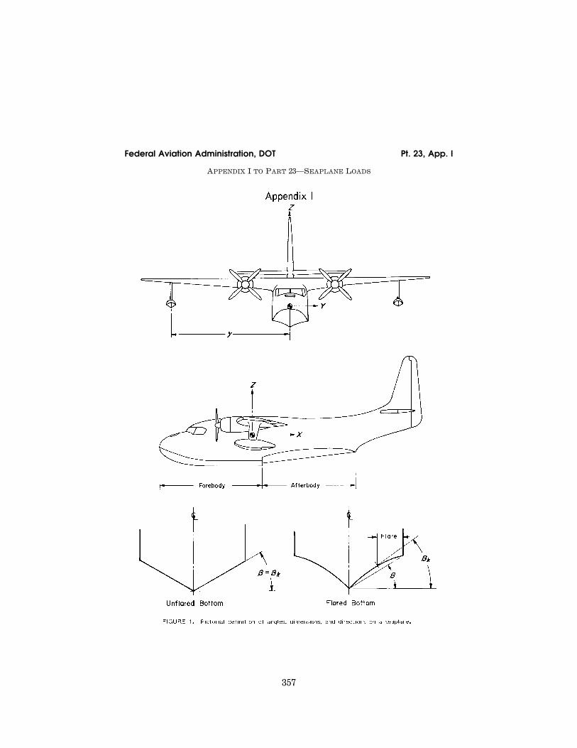
357
Federal Aviation Administration, DOT Pt. 23, App. I
APPENDIX I TO PART 23—SEAPLANE LOADS
VerDate Mar<15>2010 14:10 Mar 01, 2011 Jkt 223043 PO 00000 Frm 00367 Fmt 8010 Sfmt 8006 Y:\SGML\223043.XXX 223043 EC
28S
E91
.031
</G
PH
>
ww
oods
2 on
DS
K1D
XX
6B1P
RO
D w
ith C
FR
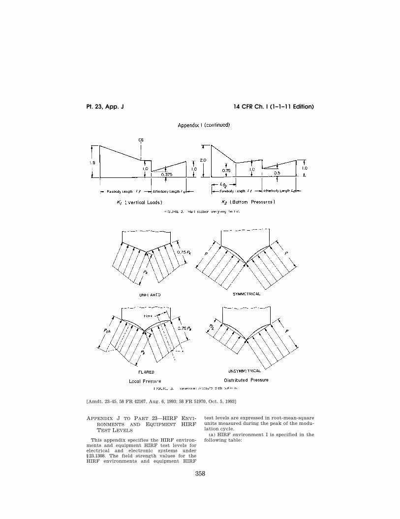
358
14 CFR Ch. I (1–1–11 Edition) Pt. 23, App. J
[Amdt. 23–45, 58 FR 42167, Aug. 6, 1993; 58 FR 51970, Oct. 5, 1993]
APPENDIX J TO PART 23—HIRF ENVI-RONMENTS AND EQUIPMENT HIRF TEST LEVELS
This appendix specifies the HIRF environ-ments and equipment HIRF test levels for electrical and electronic systems under § 23.1308. The field strength values for the HIRF environments and equipment HIRF
test levels are expressed in root-mean-square units measured during the peak of the modu-lation cycle.
(a) HIRF environment I is specified in the following table:
VerDate Mar<15>2010 14:10 Mar 01, 2011 Jkt 223043 PO 00000 Frm 00368 Fmt 8010 Sfmt 8002 Y:\SGML\223043.XXX 223043 EC
28S
E91
.032
</G
PH
>
ww
oods
2 on
DS
K1D
XX
6B1P
RO
D w
ith C
FR
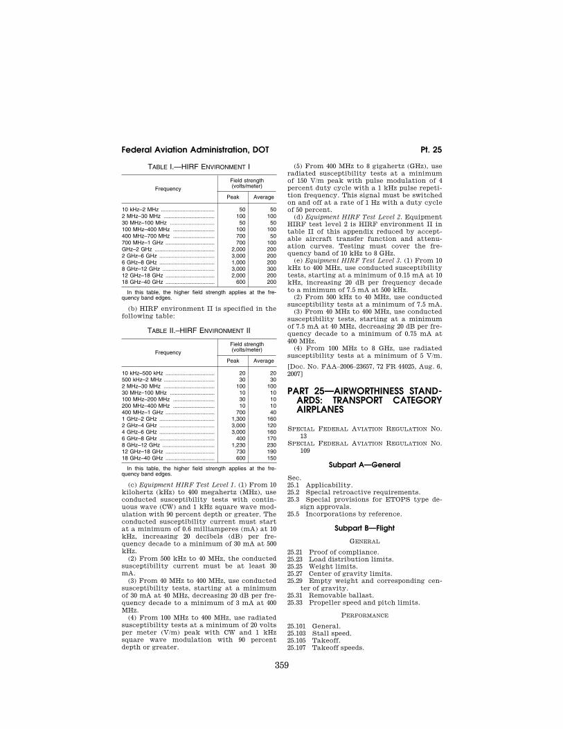
359
Federal Aviation Administration, DOT Pt. 25
TABLE I.—HIRF ENVIRONMENT I
Frequency
Field strength (volts/meter)
Peak Average
10 kHz–2 MHz ................................... 50 50 2 MHz–30 MHz ................................. 100 100 30 MHz–100 MHz ............................. 50 50 100 MHz–400 MHz ........................... 100 100 400 MHz–700 MHz ........................... 700 50 700 MHz–1 GHz ................................ 700 100 GHz–2 GHz ....................................... 2,000 200 2 GHz–6 GHz .................................... 3,000 200 6 GHz–8 GHz .................................... 1,000 200 8 GHz–12 GHz .................................. 3,000 300 12 GHz–18 GHz ................................ 2,000 200 18 GHz–40 GHz ................................ 600 200
In this table, the higher field strength applies at the fre-quency band edges.
(b) HIRF environment II is specified in the following table:
TABLE II.–HIRF ENVIRONMENT II
Frequency
Field strength (volts/meter)
Peak Average
10 kHz–500 kHz ................................ 20 20 500 kHz–2 MHz ................................. 30 30 2 MHz–30 MHz ................................. 100 100 30 MHz–100 MHz ............................. 10 10 100 MHz–200 MHz ........................... 30 10 200 MHz–400 MHz ........................... 10 10 400 MHz–1 GHz ................................ 700 40 1 GHz–2 GHz .................................... 1,300 160 2 GHz–4 GHz .................................... 3,000 120 4 GHz–6 GHz .................................... 3,000 160 6 GHz–8 GHz .................................... 400 170 8 GHz–12 GHz .................................. 1,230 230 12 GHz–18 GHz ................................ 730 190 18 GHz–40 GHz ................................ 600 150
In this table, the higher field strength applies at the fre-quency band edges.
(c) Equipment HIRF Test Level 1. (1) From 10 kilohertz (kHz) to 400 megahertz (MHz), use conducted susceptibility tests with contin-uous wave (CW) and 1 kHz square wave mod-ulation with 90 percent depth or greater. The conducted susceptibility current must start at a minimum of 0.6 milliamperes (mA) at 10 kHz, increasing 20 decibels (dB) per fre-quency decade to a minimum of 30 mA at 500 kHz.
(2) From 500 kHz to 40 MHz, the conducted susceptibility current must be at least 30 mA.
(3) From 40 MHz to 400 MHz, use conducted susceptibility tests, starting at a minimum of 30 mA at 40 MHz, decreasing 20 dB per fre-quency decade to a minimum of 3 mA at 400 MHz.
(4) From 100 MHz to 400 MHz, use radiated susceptibility tests at a minimum of 20 volts per meter (V/m) peak with CW and 1 kHz square wave modulation with 90 percent depth or greater.
(5) From 400 MHz to 8 gigahertz (GHz), use radiated susceptibility tests at a minimum of 150 V/m peak with pulse modulation of 4 percent duty cycle with a 1 kHz pulse repeti-tion frequency. This signal must be switched on and off at a rate of 1 Hz with a duty cycle of 50 percent.
(d) Equipment HIRF Test Level 2. Equipment HIRF test level 2 is HIRF environment II in table II of this appendix reduced by accept-able aircraft transfer function and attenu-ation curves. Testing must cover the fre-quency band of 10 kHz to 8 GHz.
(e) Equipment HIRF Test Level 3. (1) From 10 kHz to 400 MHz, use conducted susceptibility tests, starting at a minimum of 0.15 mA at 10 kHz, increasing 20 dB per frequency decade to a minimum of 7.5 mA at 500 kHz.
(2) From 500 kHz to 40 MHz, use conducted susceptibility tests at a minimum of 7.5 mA.
(3) From 40 MHz to 400 MHz, use conducted susceptibility tests, starting at a minimum of 7.5 mA at 40 MHz, decreasing 20 dB per fre-quency decade to a minimum of 0.75 mA at 400 MHz.
(4) From 100 MHz to 8 GHz, use radiated susceptibility tests at a minimum of 5 V/m.
[Doc. No. FAA–2006–23657, 72 FR 44025, Aug. 6, 2007]
PART 25—AIRWORTHINESS STAND-ARDS: TRANSPORT CATEGORY AIRPLANES
SPECIAL FEDERAL AVIATION REGULATION NO. 13
SPECIAL FEDERAL AVIATION REGULATION NO. 109
Subpart A—General
Sec. 25.1 Applicability. 25.2 Special retroactive requirements. 25.3 Special provisions for ETOPS type de-
sign approvals. 25.5 Incorporations by reference.
Subpart B—Flight
GENERAL
25.21 Proof of compliance. 25.23 Load distribution limits. 25.25 Weight limits. 25.27 Center of gravity limits. 25.29 Empty weight and corresponding cen-
ter of gravity. 25.31 Removable ballast. 25.33 Propeller speed and pitch limits.
PERFORMANCE
25.101 General. 25.103 Stall speed. 25.105 Takeoff. 25.107 Takeoff speeds.
VerDate Mar<15>2010 14:10 Mar 01, 2011 Jkt 223043 PO 00000 Frm 00369 Fmt 8010 Sfmt 8010 Y:\SGML\223043.XXX 223043ww
oods
2 on
DS
K1D
XX
6B1P
RO
D w
ith C
FR

![Pt. 796 40 CFR Ch. I (71 02 Edition) - GPO Pt. 796 40 CFR Ch. I (7–1–02 Edition) PART 796—CHEMICAL FATE TESTING GUIDELINES Subpart A [Reserved] Subpart B—Physical and Chemical](https://static.fdocuments.in/doc/165x107/5afe67dd7f8b9a864d8ee3ef/pt-796-40-cfr-ch-i-71-02-edition-gpo-pt-796-40-cfr-ch-i-7102-edition.jpg)