
Pt. 111 46 CFR Ch. I (101 01 Edition) - gpo.gov · PDF filePt. 111 46 CFR Ch. I...
43
210 46 CFR Ch. I (10–1–01 Edition) Pt. 111 (b) Repairs, alterations, or modifica- tions that affect the safety of the ves- sel. [CGD 94–108, 61 FR 28275, June 4, 1996] PART 111—ELECTRIC SYSTEMS— GENERAL REQUIREMENTS Subpart 111.01—General Sec. 111.01–1 General. 111.01–3 Placement of equipment. 111.01–5 Protection from bilge water. 111.01–7 Accessibility and spacing. 111.01–9 Degrees of protection. 111.01–11 Corrosion-resistant parts. 111.01–13 Limitations on porcelain use. 111.01–15 Temperature ratings. 111.01–17 Voltage and frequency variations. 111.01–19 Inclination of the vessel. Subpart 111.05—Equipment Ground, Ground Detection, and Grounded Systems 111.05–1 Purpose. EQUIPMENT GROUND 111.05–3 Design, construction, and installa- tion; general. 111.05–7 Armored and metallic-sheathed cable. 111.05–9 Masts. SYSTEM GROUNDING 111.05–11 Hull return. 111.05–13 Grounding connection. 111.05–15 Neutral grounding. 111.05–17 Generation and distribution sys- tem grounding. 111.05–19 Tank vessels; grounded distribu- tion systems. GROUND DETECTION 111.05–21 Ground detection. 111.05–23 Location of ground indicators. 111.05–25 Ungrounded systems. 111.05–27 Grounded neutral alternating cur- rent systems. 111.05–29 Dual voltage direct current sys- tems. GROUNDED CONDUCTORS 111.05–31 Grounding conductors for systems. 111.05–33 Equipment safety grounding (bonding) conductors. 111.05–37 Overcurrent devices. Subpart 111.10—Power Supply 111.10–1 Definitions. 111.10–3 Two generating sources. 111.10–4 Power requirements, generating sources. 111.10–5 Multiple energy sources. 111.10–7 Dead ship. 111.10–9 Ship’s service supply transformers; two required. Subpart 111.12—Generator Construction and Circuits 111.12–1 Prime movers. 111.12–3 Excitation. 111.12–5 Generator construction and testing. 111.12–7 Voltage regulation and parallel op- eration. 111.12–9 Generator cables. 111.12–11 Generator protection. 111.12–13 Propulsion generator protection. Subpart 111.15—Storage Batteries and Bat- tery Chargers: Construction and Instal- lation 111.15–1 General. 111.15–2 Battery construction. 111.15–3 Battery categories. 111.15–5 Battery installation. 111.15–10 Ventilation. 111.15–20 Conductors. 111.15–25 Overload and reverse current pro- tection. 111.15–30 Battery chargers. Subpart 111.20—Transformer Construction, Installation, and Protection 111.20–1 General requirements. 111.20–5 Temperature rise. 111.20–10 Autotransformers. 111.20–15 Transformer overcurrent protec- tion. Subpart 111.25—Motors 111.25–1 General requirements 111.25–5 Marking. 111.25–15 Duty cycle. Subpart 111.30—Switchboards 111.30–1 Location and installation. 111.30–3 Accessibility of switchboard compo- nents and connections. 111.30–4 Circuit breakers removable from the front. 111.30–5 Construction. 111.30–11 Deck coverings. 111.30–15 Nameplates. 111.30–17 Protection of instrument circuits. 111.30–19 Buses and wiring. 111.30–24 Generation systems greater than 3000 kw. 111.30–25 Alternating-current ship’s service switchboards. 111.30–27 Direct current ship’s service switchboards. 111.30–29 Emergency switchboards. VerDate 11<MAY>2000 13:58 Oct 22, 2001 Jkt 194182 PO 00000 Frm 00210 Fmt 8010 Sfmt 8010 Y:\SGML\194182T.XXX pfrm04 PsN: 194182T
Transcript of Pt. 111 46 CFR Ch. I (101 01 Edition) - gpo.gov · PDF filePt. 111 46 CFR Ch. I...
210
46 CFR Ch. I (10–1–01 Edition)Pt. 111
(b) Repairs, alterations, or modifica-tions that affect the safety of the ves-sel.
[CGD 94–108, 61 FR 28275, June 4, 1996]
PART 111—ELECTRIC SYSTEMS—GENERAL REQUIREMENTS
Subpart 111.01—General
Sec.111.01–1 General.111.01–3 Placement of equipment.111.01–5 Protection from bilge water.111.01–7 Accessibility and spacing.111.01–9 Degrees of protection.111.01–11 Corrosion-resistant parts.111.01–13 Limitations on porcelain use.111.01–15 Temperature ratings.111.01–17 Voltage and frequency variations.111.01–19 Inclination of the vessel.
Subpart 111.05—Equipment Ground,Ground Detection, and Grounded Systems
111.05–1 Purpose.
EQUIPMENT GROUND
111.05–3 Design, construction, and installa-tion; general.
111.05–7 Armored and metallic-sheathedcable.
111.05–9 Masts.
SYSTEM GROUNDING
111.05–11 Hull return.111.05–13 Grounding connection.111.05–15 Neutral grounding.111.05–17 Generation and distribution sys-
tem grounding.111.05–19 Tank vessels; grounded distribu-
tion systems.
GROUND DETECTION
111.05–21 Ground detection.111.05–23 Location of ground indicators.111.05–25 Ungrounded systems.111.05–27 Grounded neutral alternating cur-
rent systems.111.05–29 Dual voltage direct current sys-
tems.
GROUNDED CONDUCTORS
111.05–31 Grounding conductors for systems.111.05–33 Equipment safety grounding
(bonding) conductors.111.05–37 Overcurrent devices.
Subpart 111.10—Power Supply
111.10–1 Definitions.111.10–3 Two generating sources.111.10–4 Power requirements, generating
sources.
111.10–5 Multiple energy sources.111.10–7 Dead ship.111.10–9 Ship’s service supply transformers;
two required.
Subpart 111.12—Generator Constructionand Circuits
111.12–1 Prime movers.111.12–3 Excitation.111.12–5 Generator construction and testing.111.12–7 Voltage regulation and parallel op-
eration.111.12–9 Generator cables.111.12–11 Generator protection.111.12–13 Propulsion generator protection.
Subpart 111.15—Storage Batteries and Bat-tery Chargers: Construction and Instal-lation
111.15–1 General.111.15–2 Battery construction.111.15–3 Battery categories.111.15–5 Battery installation.111.15–10 Ventilation.111.15–20 Conductors.111.15–25 Overload and reverse current pro-
tection.111.15–30 Battery chargers.
Subpart 111.20—Transformer Construction,Installation, and Protection
111.20–1 General requirements.111.20–5 Temperature rise.111.20–10 Autotransformers.111.20–15 Transformer overcurrent protec-
tion.
Subpart 111.25—Motors
111.25–1 General requirements111.25–5 Marking.111.25–15 Duty cycle.
Subpart 111.30—Switchboards
111.30–1 Location and installation.111.30–3 Accessibility of switchboard compo-
nents and connections.111.30–4 Circuit breakers removable from
the front.111.30–5 Construction.111.30–11 Deck coverings.111.30–15 Nameplates.111.30–17 Protection of instrument circuits.111.30–19 Buses and wiring.111.30–24 Generation systems greater than
3000 kw.111.30–25 Alternating-current ship’s service
switchboards.111.30–27 Direct current ship’s service
switchboards.111.30–29 Emergency switchboards.
VerDate 11<MAY>2000 13:58 Oct 22, 2001 Jkt 194182 PO 00000 Frm 00210 Fmt 8010 Sfmt 8010 Y:\SGML\194182T.XXX pfrm04 PsN: 194182T

211
Coast Guard, DOT Pt. 111
Subpart 111.33—Power SemiconductorRectifier Systems
111.33–1 General.111.33–3 Nameplate data.111.33–5 Installation.111.33–7 Alarms and shutdowns.111.33–9 Ventilation exhaust.111.33–11 Propulsion systems.
Subpart 111.35—Electric Propulsion
111.35–1 Electrical propulsion installations.
Subpart 111.40—Panelboards
111.40–1 Panelboard standard.111.40–5 Enclosure.111.40–7 Location.111.40–9 Locking device.111.40–11 Numbered switching unit and pan-
elboard directory.111.40–13 Rating.111.40–15 Overcurrent device.
Subpart 111.50—Overcurrent Protection
111.50–1 Protection of equipment.111.50–2 Systems integration.111.50–3 Protection of conductors.111.50–5 Location of overcurrent protective
devices.111.50–7 Enclosures.111.50–9 Disconnecting and guarding.
Subpart 111.51—Coordination ofOvercurrent Protective Devices
111.51–1 Purpose.111.51–3 Protection of vital equipment.
Subpart 111.52—Calculation of Short-Circuit Currents
111.52–1 General.111.52–3 Systems below 1500 kilowatts.111.52–5 Systems 1500 kilowatts or above.
Subpart 111.53—Fuses
111.53–1 General.
Subpart 111.54—Circuit Breakers
111.54–1 Circuit breakers.111.54–3 Remote control.
Subpart 111.55—Switches
111.55–1 General.111.55–3 Circuit connections.
Subpart 111.59—Busways
111.59–1 General.111.59–3 No mechanical cooling.
Subpart 111.60—Wiring Materials andMethods
111.60–1 Cable construction and testing.111.60–2 Specialty cable for communication
and RF applications.111.60–3 Cable application.111.60–4 Minimum cable conductor size.111.60–5 Cable installation.111.60–6 Fiber optic cable.111.60–7 Demand loads.111.60–9 Segregation of vital circuits.111.60–11 Wire.111.60–13 Flexible electric cord and cables.111.60–17 Connections and terminations.111.60–19 Cable splices.111.60–21 Cable insulation tests.111.60–23 Metal-clad (Type MC) cable.
Subpart 111.70—Motor Circuits, Controllers,and Protection
111.70–1 General.111.70–3 Motor controllers and motor con-
trol centers.111.70–5 Heater circuits.111.70–7 Remote control, interlock, and in-
dicator circuits.
Subpart 111.75—Lighting Circuits andProtection
111.75–1 Lighting feeders.111.75–5 Lighting branch circuits.111.75–15 Lighting requirements.111.75–16 Lighting of survival craft and res-
cue boats.111.75–17 Navigation lights.111.75–18 Signaling lights.111.75–20 Lighting fixtures.
Subpart 111.77—Appliances andAppliance Circuits
111.77–1 Overcurrent protection.111.77–3 Appliances.
Subpart 111.79—Receptacles
111.79–1 Receptacle outlets; general.111.79–3 Grounding pole.111.79–9 Transmitting power between recep-
tacles.111.79–11 Lifeboat receptacles.111.79–13 Different voltages and power
types.111.79–15 Receptacles for refrigerated con-
tainers.
Subpart 111.81—Outlet Boxes and JunctionBoxes
111.81–1 Outlet boxes and junction boxes;general.
111.81–3 Cables entering boxes.
VerDate 11<MAY>2000 13:58 Oct 22, 2001 Jkt 194182 PO 00000 Frm 00211 Fmt 8010 Sfmt 8010 Y:\SGML\194182T.XXX pfrm04 PsN: 194182T

212
46 CFR Ch. I (10–1–01 Edition)§ 111.01–1
Subpart 111.83—Shore Connection Boxes
111.83–1 General.111.83–5 Bottom entrance and protected en-
closures.
Subpart 111.85—Electric Oil ImmersionHeaters
111.85–1 Electric oil immersion heaters.
Subpart 111.87—Electric Air HeatingEquipment
111.87–1 Applicability.111.87–3 General requirements.
Subpart 111.91—Elevators andDumbwaiters
111.91–1 Power, control, and interlock cir-cuits.
Subpart 111.95—Electric Power-OperatedBoat Winches
111.95–1 Applicability.111.95–3 General requirements.111.95–7 Wiring of boat winch components.
Subpart 111.97—Electric Power-OperatedWatertight Door Systems
111.97–1 Applicability.111.97–3 General requirements.111.97–5 Electric and hydraulic power sup-
ply.111.97–7 Distribution.111.97–9 Overcurrent protection.
Subpart 111.99—Fire Door Holding andRelease Systems
111.99–1 Applicability.111.99–3 Definitions.111.99–5 General.
Subpart 111.101—Submersible Motor-Driven Bilge Pumps
111.101–1 Applicability.111.101–3 General requirements.
Subpart 111.103—Remote StoppingSystems
111.103–1 Power ventilation systems exceptmachinery space ventilation systems.
111.103–3 Machinery space ventilation.111.103–7 Ventilation stop stations.111.103–9 Machinery stop stations.
Subpart 111.105—Hazardous Locations
111.105–1 Applicability.111.105–3 General requirements.111.105–5 System integrity.111.105–7 Approved equipment.
111.105–9 Explosionproof and flameproofequipment.
111.105–11 Intrinsically safe systems.111.105–15 Additional methods of protection.111.105–17 Wiring methods for hazardous lo-
cations.111.105–19 Switches.111.105–21 Ventilation.111.105–27 Belt drives.111.105–29 Combustible liquid cargo carriers.111.105–31 Flammable or combustible cargo
with a flashpoint below 60 degrees C (140degrees F), liquid sulphur carriers and in-organic acid carriers.
111.105–32 Bulk liquefied flammable gas andammonia carriers.
111.105–33 Mobile offshore drilling units.111.105–35 Vessels carrying coal.111.105–37 Flammable anesthetics.111.105–39 Additional requirements for ves-
sels carrying vehicles with fuel in theirtanks.
111.105–40 Additional requirements for RO/RO vessels.
111.105–41 Battery rooms.111.105–43 Paint stowage or mixing spaces.111.105–45 Vessels carrying agricultural
products.
Subpart 111.107—Industrial Systems
111.107–1 Industrial systems.
AUTHORITY: 46 U.S.C. 3306, 3703; 49 CFR 1.46.
SOURCE: CGD 74–125A, 47 FR 15236, Apr. 8,1982, unless otherwise noted.
Subpart 111.01—General
§ 111.01–1 General.
(a) Electric installations on vesselsmust ensure:
(1) Maintenance of services necessaryfor safety under normal and emergencyconditions.
(2) Protection of passengers, crew,other persons, and the vessel from elec-trical hazards.
(3) Maintenance of system integritythrough compliance with the applica-ble system requirements (IEEE, NEC,IEC, etc.) to which plan review hasbeen approved.
(b) Combustible material should beavoided in the construction of elec-trical equipment.
[CGD 74–125A, 47 FR 15236, Apr. 8, 1982, asamended by CGD 94–108, 61 FR 28275, June 4,1996; 62 FR 23907, May 1, 1997]
VerDate 11<MAY>2000 13:58 Oct 22, 2001 Jkt 194182 PO 00000 Frm 00212 Fmt 8010 Sfmt 8010 Y:\SGML\194182T.XXX pfrm04 PsN: 194182T
213
Coast Guard, DOT § 111.01–15
§ 111.01–3 Placement of equipment.(a) Electric equipment must be ar-
ranged, as far as practicable, to pre-vent mechanical damage to the equip-ment from the accumulation of dust,oil vapors, steam, or dripping liquids.
(b) Apparatus that may arc must beventilated or be in ventilated compart-ments in which flammable gases, acidfumes, and oil vapors cannot accumu-late. Skylights and ventilators must bearranged to prevent flooding of the ap-paratus.
§ 111.01–5 Protection from bilge water.Each of the following in or around
the bilge area must be arranged or con-structed so that it cannot be damagedby bilge water:
(a) Generators.(b) Motors.(c) Electric coupling.(d) Electric cable.
[CGD 94–108, 61 FR 28275, June 4, 1996]
§ 111.01–7 Accessibility and spacing.(a) The design and arrangement of
electric apparatus must afford accessi-bility to each part as needed to facili-tate proper inspection, adjustment,maintenance, or replacement.
(b) Within an enclosure, the spacingbetween energized components (or be-tween an energized component andground) must be to the appropriate in-dustry standard for the voltage andcurrent utilized in the circuit. Addi-tionally, spacing within any enclosuremust be sufficient to facilitate serv-icing.
[CGD 94–108, 61 FR 28275, June 4, 1996]
§ 111.01–9 Degrees of protection.(a) Interior electrical equipment ex-
posed to dripping liquids or fallingsolid particles must be manufacturedto at least NEMA 250 Type 2 or IEC IP22 degree of protection as appropriatefor the service intended.
(b) Electrical equipment in locationsrequiring exceptional degrees of pro-tection as defined in § 110.15–1 of thischapter must be enclosed to meet atleast the minimum degrees of protec-tion in ABS Rules for Building andClassing Steel Vessels, table 4/5B.1, orappropriate NEMA 250 Type for theservice intended. Each enclosure must
be designed in such a way that thetotal rated temperature of the equip-ment inside the enclosure is not ex-ceeded.
(c) Central control consoles and simi-lar control enclosures must be manu-factured to at least NEMA 250 Type 2or IEC IP 22 degree of protection re-gardless of location.
(d) Equipment for interior locationsnot requiring exceptional degrees ofprotection must be manufactured to atleast NEMA 250 Type 1 with dripshieldor IEC IP 11.
NOTE TO § 111.01–9: The degrees of protec-tion specified in this section are described inNEMA Standards Publication No. 250 andIEC IP Code 529 and designated in ABS Rulesfor Building and Classing Steel Vessels, table4/5B.1.
[CGD 94–108, 61 FR 28275, June 4, 1996, asamended at 62 FR 23907, May 1, 1997]
§ 111.01–11 Corrosion-resistant parts.
Each enclosure and part of electricequipment that can be damaged by cor-rosion must be made of corrosion-re-sistant materials or of materials hav-ing a corrosion resistant finish.
§ 111.01–13 Limitations on porcelainuse.
Porcelain must not be used for lampsockets, switches, receptacles, fuseblocks, or other electric equipmentwhere the item is solidly mounted bymachine screws or their equivalent, un-less the porcelain piece is resilientlymounted.
§ 111.01–15 Temperature ratings.
(a) In this subchapter, an ambienttemperature of 40°C is assumed exceptas otherwise stated.
(b) A 50°C ambient temperature is as-sumed for all rotating electrical ma-chinery in boiler rooms, engine rooms,auxiliary machinery rooms, and weath-er decks, unless it can be shown that a45°C ambient temperature will not beexceeded in these spaces.
(c) A 45°C ambient temperature is as-sumed for cable and all other non-ro-tating electrical equipment in boilerrooms, in engine rooms, in auxiliarymachinery rooms, and on weatherdecks. For installations using UL 489SA marine type circuit breakers the
VerDate 11<MAY>2000 13:58 Oct 22, 2001 Jkt 194182 PO 00000 Frm 00213 Fmt 8010 Sfmt 8010 Y:\SGML\194182T.XXX pfrm04 PsN: 194182T
214
46 CFR Ch. I (10–1–01 Edition)§ 111.01–17
ambient temperature for that compo-nent is assumed to be 40°C. For instal-lations using Navy type circuit break-ers the ambient temperature for thatcomponent is assumed to be 50°C.
(d) Unless otherwise indicated in thissubchapter, a 55°C ambient tempera-ture is assumed for all control and in-strumentation equipment.
(e) If electrical equipment is utilizedin a space in which the equipment’srated ambient temperature is belowthe assumed ambient temperature ofthe space, its load must be derated.The assumed ambient temperature ofthe space plus the equipment’s actualtemperature rise at its derated loadmust not exceed the equipment’s totalrated temperature (equipment’s ratedambient temperature plus its ratedtemperature rise).
[CGD 94–108, 61 FR 28276, June 4, 1996, asamended at 62 FR 23907, May 1, 1997]
§ 111.01–17 Voltage and frequencyvariations.
Unless otherwise stated, electricalequipment must function at variationsof at least ±5 percent of rated fre-quency and +6 percent to ¥10 percentof rated voltage. This limitation doesnot address transient conditions.
[CGD 94–108, 61 FR 28276, June 4, 1996]
§ 111.01–19 Inclination of the vessel.
(a) All electrical equipment must bedesigned and installed to operate forthe particular location and environ-ment in which it is to be used. Addi-tionally, electrical equipment nec-essary for the maneuvering, naviga-tion, and safety of the vessel or its per-sonnel must be designed and installedto operate under any combination ofthe following conditions:
(1) 15 degrees static list, 22.5 degreesdynamic roll; and
(2) 7.5 degrees static trim.(b) All emergency installations must
be designed and installed to operatewhen the vessel is at 22.5 degrees listand 10 degrees trim.
[CGD 94–108, 61 FR 28276, June 4, 1996, asamended at 62 FR 23907, May 1, 1997]
Subpart 111.05—EquipmentGround, Ground Detection,and Grounded Systems
§ 111.05–1 Purpose.This subpart contains requirements
for the grounding of electric systems,circuits, and equipment.
NOTE: Circuits are grounded to limit exces-sive voltage from lightning, transient surges,and unintentional contact with higher volt-age lines, and to limit the voltage to groundduring normal operation. Conductive mate-rials enclosing electric conductors andequipment, or forming part of that equip-ment, are grounded to prevent a voltageabove ground on the enclosure materials.
[CGD 74–125A, 47 FR 15236, Apr. 8, 1982, asamended by CGD 94–108, 61 FR 28276, June 4,1996]
EQUIPMENT GROUND
§ 111.05–3 Design, construction, and in-stallation; general.
(a) An electric apparatus must be de-signed, constructed, and installed toprevent any person from accidentallycontacting energized parts.
(b) Exposed, noncurrent-carryingmetal parts of fixed equipment thatmay become energized because of anycondition must be grounded.
(c) Exposed, noncurrent-carryingmetal parts of portable equipmentmust be grounded through a conductorin the supply cable to the groundingpole in the receptacle.
(d) If the installation of the elec-trical equipment does not ensure apositive ground to the metal hull orequivalent conducting body, the appa-ratus must be grounded to the hullwith a grounding conductor.
§ 111.05–7 Armored and metallic-sheathed cable.
When installed, the metallic armoror sheath must meet the installationrequirements of IEC 92–3 or section 20of IEEE Std 45.
[CGD 94–108, 61 FR 28276, June 4, 1996]
§ 111.05–9 Masts.Each nonmetallic mast and topmast
must have a lightning ground con-ductor in accordance with section 10 ofIEC 92–401.
[CGD 94–108, 62 FR 23907, May 1, 1997]
VerDate 11<MAY>2000 13:58 Oct 22, 2001 Jkt 194182 PO 00000 Frm 00214 Fmt 8010 Sfmt 8010 Y:\SGML\194182T.XXX pfrm04 PsN: 194182T
215
Coast Guard, DOT § 111.05–23
SYSTEM GROUNDING
§ 111.05–11 Hull return.
(a) A vessel’s hull must not carrycurrent as a conductor except for thefollowing systems:
(1) Impressed current cathodic pro-tection systems.
(2) Limited and locally grounded sys-tems, such as a battery system for en-gine starting that has a one-wire sys-tem and the ground lead connected tothe engine.
(3) Insulation level monitoring de-vices if the circulation current doesnot exceed 30 milliamperes under themost unfavorable conditions.
(4) Welding systems with hull returnexcept vessels subject to 46 CFR Sub-chapter D.
§ 111.05–13 Grounding connection.Each grounded system must have
only one point of connection to groundregardless of the number of powersources operating in parallel in the sys-tem.
§ 111.05–15 Neutral grounding.(a) Each propulsion, power, lighting,
or distribution system having a neutralbus or conductor must have the neutralgrounded.
(b) The neutral of a dual-voltage sys-tem must be solidly grounded at thegenerator switchboard.
§ 111.05–17 Generation and distribu-tion system grounding.
The neutral of each grounded genera-tion and distribution system must:
(a) Be grounded at the generatorswitchboard, except the neutral of anemergency power generation systemmust be grounded with:
(1) No direct ground connection atthe emergency switchboard;
(2) The neutral bus permanently con-nected to the neutral bus on the mainswitchboard; and
(3) No switch, circuit breaker, or fusein the neutral conductor of the bus-tiefeeder connecting the emergencyswitchboard to the main switchboard;and
(b) Have the ground connection ac-cessible for checking the insulation re-sistance of the generator to ground be-
fore the generator is connected to thebus.
§ 111.05–19 Tank vessels; grounded dis-tribution systems.
(a) If the voltage of a distributionsystem is less than 1,000 volts, line toline, a tank vessel must not have agrounded distribution system.
(b) If the voltage of a distributionsystem on a tank vessel is 1,000 volts orgreater, line to line, and the distribu-tion system is grounded (includinghigh-impedance grounding), any result-ing current must not flow through ahazardous (classified) location.
[CGD 94–108, 61 FR 28276, June 4, 1996, asamended at 62 FR 23907, May 1, 1997]
GROUND DETECTION
§ 111.05–21 Ground detection.There must be ground detection for
each:(a) Electric propulsion system;(b) Ship’s service power system;(c) Lighting system; and(d) Power or lighting distribution
system that is isolated from the ship’sservice power and lighting system bytransformers, motor generator sets, orother devices.
§ 111.05–23 Location of ground indica-tors.
Ground indicators must:(a) Be at the vessel’s ship’s service
generator distribution switchboard forthe normal power, normal lighting, andemergency lighting systems;
(b) Be at the propulsion switchboardfor propulsion systems; and
(c) Be readily accessible.(d) Be provided (at the distribution
switchboard or at another location,such as a centralized monitoring posi-tion for the circuit affected) for eachfeeder circuit that is isolated from themain source by a transformer or otherdevice.
NOTE TO PARAGRAPH (d): An alarm contactor indicating device returned to the mainswitchboard via a control cable, that allowsthe detecting equipment to remain near thetransformer or other isolating device forlocal troubleshooting, is allowed.
[CGD 74–125A, 47 FR 15236, Apr. 8, 1982, asamended by CGD 94–108, 61 FR 28276, June 4,1996; 62 FR 23907, May 1, 1997]
VerDate 11<MAY>2000 13:58 Oct 22, 2001 Jkt 194182 PO 00000 Frm 00215 Fmt 8010 Sfmt 8010 Y:\SGML\194182T.XXX pfrm04 PsN: 194182T

216
46 CFR Ch. I (10–1–01 Edition)§ 111.05–25
§ 111.05–25 Ungrounded systems.
Each ungrounded system must beprovided with a suitably sensitiveground detection system located at therespective switchboard which providescontinuous indication of circuit statusto ground with a provision to momen-tarily remove the indicating devicefrom the reference ground.
[CGD 94–108, 61 FR 28276, June 4, 1996]
§ 111.05–27 Grounded neutral alter-nating current systems.
Grounded neutral and high-imped-ance grounded neutral alternating cur-rent systems must have a suitably sen-sitive ground detection system whichindicates current in the ground connec-tion, is able to withstand the max-imum available fault current withoutdamage, and provides continuous indi-cation of circuit status to ground. Aprovision must be included to compareindications under fault conditions withthose under normal conditions.
[CGD 94–108, 62 FR 23907, May 1, 1997]
§ 111.05–29 Dual voltage direct currentsystems.
Each dual voltage direct current sys-tem must have a suitably sensitiveground detection system which indi-cates current in the ground connection,has a range of at least 150 percent ofneutral current rating and indicatesthe polarity of the fault.
[CGD 94–108, 61 FR 28276, June 4, 1996]
GROUNDED CONDUCTORS
§ 111.05–31 Grounding conductors forsystems.
(a) A conductor for grounding a di-rect-current system must be the largerof:
(1) The largest conductor supplyingthe system; or
(2) No. 8 AWG (8.4mm2).(b) A conductor for grounding the
neutral of an alternating-current sys-tem must meet Table 111.05–31(b).
TABLE 111.05–31(b)—NEUTRAL GROUNDINGCONDUCTOR FOR ALTERNATING-CURRENTSYSTEM
Size of the largest generator cable or equiva-lent for parallel generators—AWG–MCM
(mm2)
Size of thesystem
groundingconductor—AWG(mm2)Greater than Less than or equal to
.................................... 2 (33.6) ...................... 8 (8.4)2 (33.6) ...................... 0 (53.5) ...................... 6 (13.3)0 (53.5) ...................... 3/0 (85.0) ................... 4 (21.2)3/0 (85.0) ................... 350 MCM (177) ......... 2 (33.6)350 MCM (177) ......... 600 MCM (304) ......... 0 (53.5)600 MCM (304) ......... 1100 MCM (557) ....... 2/0 (67.5)1100 MCM (557) ....... ................................... 3/0 (85.0)
§ 111.05–33 Equipment safety ground-ing (bonding) conductors.
(a) Each equipment grounding con-ductor must be sized in accordancewith article 250–95 of the National Elec-trical Code (the NEC) (NFPA 70).
(b) Each equipment grounding con-ductor (other than a system groundingconductor) of a cable must be perma-nently identified as a grounding con-ductor in accordance with the require-ments of article 310–12(b) of the NEC.
[CGD 94–108, 61 FR 28276, June 4, 1996, asamended at 62 FR 23907, May 1, 1997]
§ 111.05–37 Overcurrent devices.(a) A permanently grounded con-
ductor must not have an overcurrentdevice unless the overcurrent device si-multaneously opens each ungroundedconductor of the circuit.
(b) The neutral conductor of theemergency-main switchboard bus-tiemust not have a switch or circuitbreaker.
[CGD 94–108, 61 FR 28276, June 4, 1996]
Subpart 111.10—Power Supply
§ 111.10–1 Definitions.As used in this Subpart:(a) Ship’s service loads mean electrical
equipment for all auxiliary servicesnecessary for maintaining the vessel ina normal, operational and habitablecondition. Ship’s service loads include,but are not limited to, all safety, light-ing, ventilation, navigational, commu-nications, habitability, and propulsion
VerDate 11<MAY>2000 13:58 Oct 22, 2001 Jkt 194182 PO 00000 Frm 00216 Fmt 8010 Sfmt 8010 Y:\SGML\194182T.XXX pfrm04 PsN: 194182T
217
Coast Guard, DOT § 111.10–7
auxiliary loads. Electrical propulsionmotor, bow thruster motor, cargotransfer, drilling, cargo refrigerationfor other than Class 5.2 organic perox-ides and Class 4.1 self-reactive sub-stances, and other industrial type loadsare not included.
(b) Drilling loads means all loads asso-ciated exclusively with the drilling op-eration including power to the drilltable, mud system, and positioningequipment.
[CGD 74–125A, 47 FR 15236, Apr. 8, 1982, asamended by CGD 94–108, 61 FR 28276, June 4,1996; 62 FR 23907, May 1, 1997]
§ 111.10–3 Two generating sources.
In addition to the emergency powersources required under part 112 of thischapter, each self-propelled vessel andeach mobile offshore drilling unit musthave at least two electric generatingsources.
[CGD 94–108, 61 FR 28276, June 4, 1996]
§ 111.10–4 Power requirements, gener-ating sources.
(a) The aggregate capacity of theelectric ship’s service generatingsources required in § 111.10–3 must besufficient for the ship’s service loads.
(b) With the ship’s service generatingsource of the largest capacity stopped,the combined capacity of the remain-ing electric ship’s service generatingsource or sources must be sufficient tosupply those services necessary to pro-vide normal operational conditions ofpropulsion and safety, and minimumcomfortable conditions of habitability.Habitability services include cooking,heating, air conditioning (where in-stalled), domestic refrigeration, me-chanical ventilation, sanitation, andfresh water.
(c) The capacity of the ship’s servicegenerating sources must be sufficientfor supplying the ship’s service loadswithout the use of a generating sourcewhich is dependent upon the speed ordirection of the main propelling en-gines or shafting.
(d) Operating generators must pro-vide a continuous and uninterruptedsource of power for the ship’s serviceload under normal operational condi-tions. Any vessel speed change or
throttle movement must not cause aship’s service load power interruption.
(e) Vessels with electric propulsionthat have two or more constant-volt-age generators which supply bothship’s service and propulsion power donot need additional ship’s service gen-erators provided that with any one pro-pulsion/ship’s service generator out ofservice the capacity of the remaininggenerator(s) is sufficient for the elec-trical loads necessary to provide nor-mal operational conditions of propul-sion and safety, and minimum com-fortable conditions of habitability.
(f) A generator driven by a main pro-pulsion unit (such as a shaft generator)which is capable of providing electricalpower continuously, regardless of thespeed and direction of the propulsionshaft, may be considered one of theship’s service generating sets requiredby § 111.10–3. A main-engine-dependentgenerator which is not capable of pro-viding continuous electrical power maybe utilized as a supplemental generatorprovided that a required ship’s servicegenerator or generators having suffi-cient capacity to supply the ship’sservice loads can be automaticallybrought on line prior to the main-en-gine-dependent generator tripping off-line due to a change in the speed or di-rection of the main propulsion unit.
[CGD 94–108, 61 FR 28277, June 4, 1996; 61 FR36787, July 12, 1996]
§ 111.10–5 Multiple energy sources.Failure of any single generating set
energy source such as a boiler, diesel,gas turbine, or steam turbine must notcause all generating sets required in§ 111.10–3 to be inoperable.
§ 111.10–7 Dead ship.(a) The generating plant of each self-
propelled vessel must provide the elec-trical services necessary to start themain propulsion plant from a dead shipcondition.
(b) If the emergency generator isused for part or all of the electricpower necessary to start the main pro-pulsion plant from a dead ship condi-tion, the emergency generator must becapable of providing power to all emer-gency lighting, emergency internalcommunications systems, and fire de-tection and alarm systems in addition
VerDate 11<MAY>2000 13:58 Oct 22, 2001 Jkt 194182 PO 00000 Frm 00217 Fmt 8010 Sfmt 8010 Y:\SGML\194182T.XXX pfrm04 PsN: 194182T
218
46 CFR Ch. I (10–1–01 Edition)§ 111.10–9
to the power utilized for starting themain propulsion plant. Additional re-quirements are in § 112.05–3(c) of thischapter.
[CGD 74–125A, 47 FR 15236, Apr. 8, 1982, asamended by CGD 94–108, 61 FR 28277, June 4,1996]
§ 111.10–9 Ship’s service supply trans-formers; two required.
If transformers are used to supplythe ship’s service distribution systemrequired by this subpart for ships andmobile offshore drilling units, theremust be at least two installed, inde-pendent power transformers. With thelargest transformer out of service, thecapacity of the remaining units mustbe sufficient to supply the ship serviceloads.
NOTE TO § 111.10–9: A ship’s service supplysystem would consist of transformers, over-current protection devices, and cables, andwould normally be located in the system be-tween a medium voltage bus and a low volt-age ship’s service switchboard.
[CGD 94–108, 61 FR 28277, June 4, 1996; 61 FR33045, June 26, 1996]
Subpart 111.12—GeneratorConstruction and Circuits
§ 111.12–1 Prime movers.(a) Prime movers must meet part 58,
subpart 58.10, of this chapter, sections4/5C2.15 and 4/5C2.17 of the ABS Rulesfor Building and Classing Steel Vesselsand, for mobile offshore drilling units,section 4/3.21 of the ABS Rules forBuilding and Classing Mobile OffshoreDrilling Units. Additional require-ments for prime movers for emergencygenerators are in part 112, subpart112.50, of this chapter.
(b) Each generator prime mover musthave an overspeed device that is inde-pendent of the normal operating gov-ernor and adjusted so that the speedcannot exceed the maximum ratedspeed by more than 15 percent.
(c) Each prime mover must shutdown automatically upon loss of lubri-cating pressure to the generator bear-ings if the generator is directly coupledto the engine. If the generator is oper-ating from a power take-off, such as ashaft driven generator on a main pro-pulsion engine, the generator must
automatically declutch (disconnect)from the prime mover upon loss of lu-bricating pressure to generator bear-ings.
[CGD 94–108, 61 FR 28277, June 4, 1996; 61 FR33045, June 26, 1996, as amended at 62 FR23907, May 1, 1997]
§ 111.12–3 Excitation.
Excitation must meet sections 4/5C2.19.1, 4/5D2.5.1, 4/5D2.5.2, and 4/5D2.17.6 of the ABS Rules for Buildingand Classing Steel Vessels or, for a mo-bile offshore drilling unit, section 4/3.23of the ABS Rules for Building andClassing Mobile Offshore DrillingUnits, except a static exciter must notbe used for excitation of an emergencygenerator unless it is provided with apermanent magnet or a residual mag-netism type exciter that has the capa-bility of voltage build-up after twomonths of no operation.
[CGD 74–125A, 47 FR 15236, Apr. 8, 1982, asamended by CGD 94–108, 61 FR 28277, June 4,1996; 62 FR 23908, May 1, 1997]
§ 111.12–5 Generator construction andtesting.
Each generator must meet the appli-cable construction and test require-ments of section 4/5 of the ABS Rulesfor Building and Classing Steel Vesselsor, for mobile offshore drilling units,section 4/3 of the ABS Rules for Build-ing and Classing Mobile Offshore Drill-ing Units.
[CGD 94–108, 61 FR 28277, June 4, 1996; 61 FR33045, June 26, 1996, as amended at 62 FR23908, May 1, 1997]
§ 111.12–7 Voltage regulation and par-allel operation.
Voltage regulation and parallel oper-ation must meet sections 4/5C2.19.2, 4/5C2.19.3, 4/5C2.21.2, and 4/5C2.21.3 of theABS Rules for Building and ClassingSteel Vessels or, for mobile offshoredrilling units, sections 4/3.31 and 4/3.33of the ABS Rules for Building andClassing Mobile Offshore DrillingUnits.
[CGD 94–108, 61 FR 28277, June 4, 1996; 61 FR33045, June 26, 1996, as amended at 62 FR23908, May 1, 1997]
VerDate 11<MAY>2000 13:58 Oct 22, 2001 Jkt 194182 PO 00000 Frm 00218 Fmt 8010 Sfmt 8010 Y:\SGML\194182T.XXX pfrm04 PsN: 194182T

219
Coast Guard, DOT § 111.12–13
§ 111.12–9 Generator cables.(a) The current-carrying capacity of
generator cables must not be:(1) Less than 115 percent of the con-
tinuous generator rating; or(2) Less than 115 percent of the over-
load for a machine with a 2 hour orgreater overload rating.
(b) Generator cables must not be inthe bilges.
§ 111.12–11 Generator protection.(a) Applicability. This section applies
to each generator except a propulsiongenerator.
(b) General. Each ship’s service gener-ator and emergency generator must beprotected by an individual, tripfree, aircircuit breaker whose tripping charac-teristics can be set or adjusted toclosely match the generator capabili-ties and meet the coordination require-ments of Subpart 111.51. Each circuitbreaker must contain the trips re-quired by this section.
(c) Type of trips. A circuit breaker fora generator must:
(1) Open upon the shutting down ofthe prime mover;
(2) Have longtime overcurrent tripsor relays set as necessary to coordinatewith the trip settings of the feeder cir-cuit breakers; and
(3) Not have an instantaneous tripwith the exception that an instanta-neous trip is required if:
(i) Three or more alternating-currentgenerators can be paralleled; or
(ii) The circuit breaker is for a directcurrent generator.
(d) Setting of longtime overcurrent trips.The pickup setting of the longtimeovercurrent trip of a generator circuitbreaker must not be larger than:
(1) 115 percent of the generator ratingfor a continuous rated machine; or
(2) 115 percent of the overload ratingfor a machine with a 2-hour or greateroverload rating.
(e) Setting of instantaneous trips. Theinstantaneous trip of a generator cir-cuit breaker must be set above, but asclose as practicable to, the maximumasymmetrical short circuit availablefrom any one of the generators thatcan be paralleled.
(f) Reverse-power and reverse-currenttrips. Each generator arranged for par-
allel operation must have reverse-power or reverse-current trips.
(g) Location. A ship’s service gener-ator overcurrent protective devicemust be on the ship’s service generatorswitchboard. The generator and itsswitchboard must be in the same space.(For the purposes of this section, thefollowing are not considered separatefrom the machinery space: (1) A con-trol room that is inside of the machin-ery casing and (2) a dedicated switch-gear and semiconductor rectifier (SCR)compartment on a mobile offshoredrilling unit that is separate from butdirectly adjacent to and on the samelevel as the generator room).
(h) Three-wire, single-phase and four-wire, three-phase generators. There mustbe circuit breaker poles for each gener-ator lead, except in the neutral lead.
(i) Three-wire, direct-current genera-tors. Each three-wire, direct currentgenerator must meet the following re-quirements:
(1) Circuit breaker poles. There mustbe separate circuit breaker poles forthe positive and negative leads, and,unless the main poles provide protec-tion, for each equalizer lead. If thereare equalizer poles for a three-wiregenerator, each overload trip must beof the ‘‘Algebraic’’ type. If there is aneutral pole in the generator circuitbreaker, there must not be an overloadtrip element for the neutral pole. Inthis case, there must be a neutral over-current relay and alarm system that isset to function at a current value notmore than the neutral rating.
(2) Equalizer buses. For each three-wire generator, the circuit breakermust protect against a short circuit onthe equalizer bus.
(j) Circuit breaker reclosing. Generatorcircuit breakers must not automati-cally close after tripping.
[CGD 74–125A, 47 FR 15236, Apr. 8, 1982, asamended by CGD 81–030, 53 FR 17847, May 18,1988; CGD 94–108, 61 FR 28277, June 4, 1996; 62FR 23908, May 1, 1997]
§ 111.12–13 Propulsion generator pro-tection.
For general requirements, see§ 111.35–1 of this chapter.
VerDate 11<MAY>2000 13:58 Oct 22, 2001 Jkt 194182 PO 00000 Frm 00219 Fmt 8010 Sfmt 8010 Y:\SGML\194182T.XXX pfrm04 PsN: 194182T
220
46 CFR Ch. I (10–1–01 Edition)§ 111.15–1
Subpart 111.15—Storage Batteriesand Battery Chargers: Con-struction and Installation
§ 111.15–1 General.
Each battery must meet the require-ments of this subpart.
[CGD 94–108, 61 FR 28277, June 4, 1996]
§ 111.15–2 Battery construction.
(a) A battery cell, when inclined at 40degrees from the vertical, must notspill electrolyte.
(b) Each fully charged lead-acid bat-tery must have a specific gravity thatmeets section 16 of IEEE Std 45.
(c) Batteries must not evolve hydro-gen at a rate exceeding that of a simi-lar size lead-acid battery under similarcharging condition.
(d) Batteries must be constructed totake into account the environmentalconditions of a marine installation, in-cluding temperature, vibration, andshock.
[CGD 94–108, 61 FR 28277, June 4, 1996]
§ 111.15–3 Battery categories.
(a) A battery installation is classifiedas one of three types, based upon poweroutput of the battery charger, as fol-lows:
(1) Large. A large battery installationis one connected to a battery chargerthat has an output of more than 2 kwcomputed from the highest possiblecharging current and the rated voltageof the battery installation.
(2) Moderate. A moderate battery in-stallation is one connected to a batterycharger that has an output of between0.2 kw and 2 kw computed from thehighest possible charging current andthe rated voltage of the battery instal-lation.
(3) Small. A small battery installationis one connected to a battery chargerthat has an output of less than 0.2 kwcomputed from the highest possiblecharging current and the rated voltageof the battery installation.
(b) Batteries that generate less hy-drogen under normal charging and dis-charging conditions than an equivalentcategory of lead-acid batteries (e.g.,sealed batteries) may have their bat-
tery category reduced to an equivalentcategory of lead-acid batteries.
[CGD 74–125A, 47 FR 15236, Apr. 8, 1982, asamended by CGD 94–108, 61 FR 28278, June 4,1996]
§ 111.15–5 Battery installation.
(a) Large batteries. Each large batteryinstallation must be in a room that isonly for batteries or a box on deck. In-stalled electrical equipment must meetthe hazardous location requirements insubpart 111.105 of this part.
(b) Moderate batteries. Each moderatebattery installation must be in a bat-tery room, in a box on deck, or in a boxor locker in another space such as anengineroom, storeroom, or similarspace, except if a moderate battery in-stallation is in a ventilated compart-ment such as the engineroom and isprotected from falling objects, a box orlocker is not required. A moderate bat-tery installation must not be in asleeping space. An engine cranking bat-tery for one or more engines must be asclose as possible to the engine or en-gines.
(c) Small batteries. Small size batteryinstallations must not be located inpoorly-ventilated spaces, such as clos-ets, or in living spaces, such as state-rooms.
(d) Battery trays. Each battery traymust be chocked with wood strips ortheir equivalent to prevent movement,and each tray must have non-absorbentinsulating supports on the bottom andsimilar spacer blocks at the sides, orequivalent provisions for air circula-tion space all around each tray. Eachbattery tray must provide adequate ac-cessibility for installation, mainte-nance, and removal of the batteries.
(e) Nameplates. Each battery must beprovided with the name of its manufac-turer, model number, type designation,either the cold cranking amp rating orthe amp-hour rating at a specific dis-charge and, for a lead-acid battery, thefully charged specific gravity value.This information must be permanentlyfixed to the battery.
(f) Lining in battery rooms and lockers.(1) Each battery room and locker musthave a watertight lining that is—
(i) On each shelf to a height of atleast 76 mm (3 inches); or
VerDate 11<MAY>2000 13:58 Oct 22, 2001 Jkt 194182 PO 00000 Frm 00220 Fmt 8010 Sfmt 8010 Y:\SGML\194182T.XXX pfrm04 PsN: 194182T

221
Coast Guard, DOT § 111.15–20
(ii) On the deck to a height of atleast 152 mm (6 inches).
(2) For lead-acid batteries, the liningmust be 1.6 mm (1⁄16 inch) thick lead orother material that is corrosion-resist-ant to the electrolyte of the battery.
(3) For alkaline batteries, the liningmust be 0.8 mm (1⁄32 inch) thick steel orother material that is corrosion-resist-ant to the electrolyte of the battery.
(g) Lining of battery boxes. Each bat-tery box must have a watertight liningto a height of at least 76 mm (3 inches)that meets paragraphs (f)(2) and (f)(3)of this section.
[CGD 74–125A, 47 FR 15236, Apr. 8, 1982, asamended by CGD 94–108, 61 FR 28278, June 4,1996; 61 FR 36787, July 12, 1996; 62 FR 23908,May 1, 1997]
§ 111.15–10 Ventilation.(a) General. Each room, locker, and
box for storage batteries must be ar-ranged or ventilated to prevent accu-mulation of flammable gas.
(b) Power ventilation. If power ventila-tion is required, the following must bemet:
(1) The power ventilation systemmust be separate from ventilation sys-tems for other spaces.
(2) Electric motors must be outsidethe duct and compartment and:
(i) Have an explosion-proof motor fora Class I, Division 1, Group B location;or
(ii) Be at least 10 ft. (3 m) from theexhaust end of the duct.
(3) Each blower must have a non-sparking fan.
(4) The power ventilation systemmust be interlocked with the batterycharger so that the battery cannot becharged without ventilation.
(c) Large battery installations. Eachbattery room for large battery installa-tions must have a power exhaust ven-tilation system and have openings forintake air near the floor that allow thepassage of the quantity of air thatmust be expelled. The quantity of theair expelled must be at least:q=3.89(i)(n).where: q=quantity of expelled air in
cubic feet per hour.i=Maximum charging current during
gas formation, or one-fourth of themaximum obtainable charging cur-
rent of the charging facility, which-ever is greater.
n=Number of cells.
(d) Moderate and small battery installa-tions. Each battery room or batterylocker for moderate or small batteryinstallations must have louvers nearthe bottom of the room or locker forair, and must be ventilated by:
(1) Ventilation that meets paragraph(c) of this section;
(2) An exhaust duct:(i) That ends in a mechanically ven-
tilated space or in the weather;(ii) That extends from the top of the
room or locker to at least 3 ft. (1 m)above the top of the room or locker;
(iii) That is at an angle of 45 degreesor less from the vertical; and
(iv) That has no appliances, such asflame arresters, that impede free pas-sage of air or gas mixtures; or
(3) A duct from the top of the roomor locker to an exhaust ventilationduct.
(e) Deck boxes. Except for a deck boxfor a small battery installation, eachdeck box must have a duct from thetop of the box to at least 4 ft. (1.2 m)above the box ending in a gooseneck ormushroom head that prevents entranceof water. Holes for air must be on atleast two parallel sides of each box.
(f) Weathertight. Each deck box mustbe weathertight.
(g) Boxes for small battery installations.Each box for a small battery installa-tion must have openings near the topto allow escape of gas. If the installa-tion is in a non-environmentally-con-trolled location, the installation mustprevent the ingress of water.
[CGD 74–125A, 47 FR 15236, Apr. 8, 1982, asamended by CGD 94–108, 61 FR 28278, June 4,1996]
§ 111.15–20 Conductors.
(a) Each conductor penetration to abattery room must be made water-tight.
(b) The termination of each cablemust be sealed to prevent the entranceof electrolyte by spray or creepage.
(c) Each connecting cable must havesufficient capacity to carry the max-imum charging current or maximum
VerDate 11<MAY>2000 13:58 Oct 22, 2001 Jkt 194182 PO 00000 Frm 00221 Fmt 8010 Sfmt 8010 Y:\SGML\194182T.XXX pfrm04 PsN: 194182T

222
46 CFR Ch. I (10–1–01 Edition)§ 111.15–25
discharge current, whichever is great-er, while maintaining the proper volt-age at the load end.
[CGD 94–108, 61 FR 28278, June 4, 1996, asamended at 62 FR 23908, May 1, 1997]
§ 111.15–25 Overload and reverse cur-rent protection.
(a) An overload protective devicemust be in each battery conductor, ex-cept conductors of engine crankingbatteries and batteries with a nominalpotential of 6 volts or less. For largestorage battery installations, the over-current protective devices must benext to, but outside of, the batteryroom.
(b) Except when a rectifier is used,the charging equipment for all bat-teries with a nominal voltage morethan 20 percent of line voltage mustprotect automatically against reversalof current.
§ 111.15–30 Battery chargers.
Each battery charger enclosure mustmeet § 111.01–9. Additionally, eachcharger must be suitable for the sizeand type of battery installation that itserves. Chargers incorporating ground-ed autotransformers must not be used.Except for rectifiers, chargers with avoltage exceeding 20 percent of the linevoltage must be provided with auto-matic protection against reversal ofcurrent.
[CGD 94–108, 61 FR 28278, June 4, 1996; 61 FR36787, July 12, 1996]
Subpart 111.20—Transformer Con-struction, Installation, and Pro-tection
§ 111.20–1 General requirements.
Each transformer winding must beresistant to moisture, sea atmosphere,and oil vapor, unless special pre-cautions are taken, such as enclosingthe winding in an enclosure with a highdegree of ingress protection.
[CGD 94–108, 61 FR 28278, June 4, 1996]
§ 111.20–5 Temperature rise.
(a) The temperature rise, based on anambient temperature of 40 degrees C,must not exceed the following:
(1) For Class A insulation, 55 degreesC.
(2) For Class B insulation, 80 degreesC.
(3) For Class F insulation, 115 degreesC.
(4) For Class H insulation, 150 degreesC.
(b) If the ambient temperature ishigher than 40 degrees C, the trans-former must be derated so that thetotal temperature stated in this sec-tion is not exceeded. The temperaturemust be taken by the resistance meth-od.
§ 111.20–10 Autotransformers.
An autotransformer must not supplyfeeders or branch circuits.
§ 111.20–15 Transformer overcurrentprotection.
Each transformer must have protec-tion against overcurrent that meets ar-ticle 450 of the NEC or IEC 92–303.
[CGD 94–108, 61 FR 28278, June 4, 1996]
Subpart 111.25—Motors
§ 111.25–1 General requirements.
The requirements for generators con-tained in § 111.12–5 apply to motors.
[CGD 74–125A, 47 FR 15236, Apr. 8, 1982, asamended by CGD 94–108, 62 FR 23908, May 1,1997]
§ 111.25–5 Marking.
(a) Each motor must have a markingor nameplate that meets either article430–7 of the NEC or IEC 92–301 (clause16).
(b) The marking or nameplate foreach motor that is in a corrosive loca-tion must be corrosion-resistant.
[CGD 74–125A, 47 FR 15236, Apr. 8, 1982, asamended by CGD 94–108, 61 FR 28278, June 4,1996]
§ 111.25–15 Duty cycle.
Each motor must be rated for contin-uous duty, except a motor for an appli-cation listed in Table 111.25–15 or asimilar duty must meet the minimumshort-time rating stated in the table.
VerDate 11<MAY>2000 13:58 Oct 22, 2001 Jkt 194182 PO 00000 Frm 00222 Fmt 8010 Sfmt 8010 Y:\SGML\194182T.XXX pfrm04 PsN: 194182T

223
Coast Guard, DOT § 111.30–17
TABLE 111.25–15
Application of motor Minimum short-time rating ofmotor, in hours
Deck winch and direct actingcapstan.
Half.
Deck winch with hydraulictransmission.
Continuous at no load fol-lowed by 1⁄2 hr. at full load.
Direct acting windlass ............ One fourth.Windlass with hydraulic trans-
mission.Half hour idle pump oper-
ation, followed by 1⁄4 hr. fullload operation.
Steering gear, direct acting ... One.Steering gear, indirect drive .. Continuous operation at 15
pct. load followed by 1 hr.at full load.
Watertight door operators ...... 1⁄12.Boat winches ......................... 1⁄12.
Subpart 111.30—Switchboards§ 111.30–1 Location and installation.
Each switchboard must meet the lo-cation and installation requirements ofsection 17.1 of IEEE Std 45 or IEC 92–302, as applicable.
[CGD 94–108, 61 FR 28278, June 4, 1996]
§ 111.30–3 Accessibility of switchboardcomponents and connections.
Each component and bus bar connec-tion on a switchboard that is not acces-sible from the rear, except a bus barconnection for a draw-out type circuitbreaker, must be within 0.5 m (20 in.) ofthe front of the switchboard.
§ 111.30–4 Circuit breakers removablefrom the front.
Circuit breakers, when installed ongenerator or distribution switchboards,must be mounted or arranged in such amanner that the circuit breaker maybe removed from the front without un-bolting bus or cable connections or de-energizing the supply, unless theswitchboard is divided into sections,such that each section is capable ofproviding power to maintain the vesselin a navigable condition, and meets§ 111.30–24 (a) and (b).
[CGD 94–108, 61 FR 28278, June 4, 1996]
§ 111.30–5 Construction.(a) All low voltage and medium volt-
age switchboards (as low and mediumare determined within the standardused) must meet—
(1) For low voltages, either section17.2 of IEEE Std 45 or IEC 92–302, clause6; or
(2) For medium voltages, either sec-tion 17.3 of IEEE Std 45 or IEC 92–503,as appropriate.
(b) Each switchboard must be fittedwith a dripshield unless the switch-board is a deck-to-overhead mountedtype which cannot be subjected toleaks or falling objects.
[CGD 94–108, 61 FR 28278, June 4, 1996, asamended at 62 FR 23908, May 1, 1997]
§ 111.30–11 Deck coverings.
Non-conducting deck coverings, suchas non-conducting mats or gratings,suitable for the specific switchboardvoltage must be installed for personnelprotection at the front and rear of theswitchboard and must extend the en-tire length of, and be of sufficientwidth to suit, the operating space.
[CGD 94–108, 62 FR 23908, May 1, 1997]
§ 111.30–15 Nameplates.
(a) Each device must have a name-plate showing the device’s function.
(b) Each nameplate for a circuitbreaker must show the electrical loadserved and the setting of the circuitbreaker.
§ 111.30–17 Protection of instrumentcircuits.
(a) Each circuit that supplies a de-vice on a switchboard, except a circuitunder paragraph (b) of this section,must have overcurrent protection.
(b) A circuit that supplies a device ona switchboard must not have overloadprotection if it supplies:
(1) An electric propulsion control;(2) A voltage regulator;(3) A ship’s service generator circuit
breaker tripping control; or(4) A device that creates a hazard to
the vessel if deenergized.(c) If short circuit protection is used
in any of the circuits listed in para-graph (b) of this section, it must be setat not less than 500% of the expectedcurrent.
(d) A secondary circuit of a currenttransformer must not be fused, and thecircuit from a current transformer to adevice that is not in the switchboardmust have a high voltage protector toshort the transformer during an opencircuit.
VerDate 11<MAY>2000 13:58 Oct 22, 2001 Jkt 194182 PO 00000 Frm 00223 Fmt 8010 Sfmt 8010 Y:\SGML\194182T.XXX pfrm04 PsN: 194182T

224
46 CFR Ch. I (10–1–01 Edition)§ 111.30–19
§ 111.30–19 Buses and wiring.
(a) General. Each bus must meet therequirements of either—
(1) Section 17.11 of IEEE Std 45; or(2) IEC 92–302 (clause 6).(b) Wiring. Instrumentation and con-
trol wiring must be—(1) Suitable for installation within in
a switchboard enclosure and be ratedat 90° C or higher;
(2) Stranded copper;(3) No. 14 AWG (2.10 mm2) or larger or
must be ribbon cable or similar con-ductor size cable recommended for usein low-power instrumentation, moni-toring, or control circuits by the equip-ment manufacturer;
(4) Flame retardant meeting ANSI/UL 1581 test VW–1 or IEC 332–1; and
(5) Extra flexible, if used on a hingedpanel.
[CGD 94–108, 61 FR 28278, June 4, 1996, asamended at 62 FR 23908, May 1, 1997]
§ 111.30–24 Generation systems greaterthan 3000 kw.
Except on a non-self-propelled mobileoffshore drilling unit (MODU) and anon-self-propelled floating Outer Conti-nental Shelf facility, when the total in-stalled electric power of the ship’sservice generation system is more than3000 kW, the switchboard must havethe following:
(a) At least two sections of the mainbus that are connected by:
(1) A non-automatic circuit breaker;(2) A disconnect switch; or(3) Removable links.(b) As far as practicable, the connec-
tion of generators and duplicatedequipment equalized between the sec-tions of the main bus.
[CGD 74–125A, 47 FR 15236, Apr. 8, 1982, asamended by CGD 94–108, 61 FR 28279, June 4,1996]
§ 111.30–25 Alternating-current ship’sservice switchboards.
(a) Except as allowed in paragraph (g)of this section, each alternating-cur-rent ship’s service switchboard musthave the equipment required by para-graphs (b) through (f) of this section.
(b) For each connected generator,each switchboard must have the fol-lowing:
(1) A circuit breaker that meets§ 111.12–11 and § 111.50–5.
(2) A disconnect switch or link foreach generator conductor, except aswitchboard having a draw-out or plug-in type generator circuit breaker thatdisconnects:
(i) Each generator conductor; or(ii) If there is a switch in the gener-
ator neutral, each ungrounded con-ductor.
(3) A pilot lamp connected betweenthe generator and the circuit breaker.
(4) An ammeter with a selectorswitch that connects the ammeter toshow the current in each phase.
(5) A voltmeter with a selectorswitch that connects the voltmeter toshow the:
(i) Generator voltage of each phase;and
(ii) Bus voltage of one phase.(6) A voltage regulator and voltage
regulator functional cut-out switch.(c) For each generator that is not ex-
cited from a variable voltage or rotaryamplifier that is controlled by a volt-age regulator unit acting on the ex-citer field, each switchboard musthave:
(1) A generator field rheostat;(2) A double-pole field switch;(3) Discharge clips; and(4) A discharge resistor.(d) If generators are arranged for par-
allel operation, each switchboard musthave:
(1) A speed control for the primemover of each generator;
(2) An indicating wattmeter for eachgenerator; and
(3) A synchroscope and synchronizinglamp that have a selector switch toshow synchronization for parallelinggenerators.
(e) Each switchboard must have thefollowing:
(1) Ground detection that meets Sub-part 111.05 for the:
(i) Ship’s service power system;(ii) Normal lighting system; and(iii) Emergency lighting system.(2) A frequency meter with a selector
switch to connect the meter to eachgenerator.
(3) An exciter field rheostat.(f) For each shore power connection
each switchboard must have:(1) A circuit breaker or fused switch;
VerDate 11<MAY>2000 13:58 Oct 22, 2001 Jkt 194182 PO 00000 Frm 00224 Fmt 8010 Sfmt 8010 Y:\SGML\194182T.XXX pfrm04 PsN: 194182T
225
Coast Guard, DOT § 111.30–29
(2) A pilot light connected to theshore side of the circuit breaker orfused switch; and
(3) One of the voltmeters under para-graph (b)(5) of this section connected toshow the voltage of each phase of theshore power connection.
(g) The equipment under paragraphs(b), (d), (e), and (f) of this section, ex-cept the equipment under paragraphs(b)(1), (b)(2), and (f)(1), must be on theship’s service switchboard or on a cen-tral control console that:
(1) Is in the same control area as themain ship’s service switchboard or canremotely control the ship’s service gen-erator circuit breaker;
(2) Has a generator section that hasonly generator functions;
(3) Has the generator section seg-regated from each other console sec-tion by a fire-resistant barrier; and
(4) Has cabling from the main switch-board to the generator section of theconsole that:
(i) Has only generator control andgenerator instrumentation circuits;and
(ii) Is protected from mechanicaldamage.
§ 111.30–27 Direct current ship’s serv-ice switchboards.
(a) Each direct current ship’s serviceswitchboard must have the equipmentrequired by paragraphs (b) through (f)of this section.
(b) For each connected generator,each switchboard must have the fol-lowing:
(1) A circuit breaker that meets§ 111.12–11 and § 111.50–5.
(2) A disconnect switch or link foreach generator conductor, except aswitchboard having a draw-out or plug-in type generator circuit breaker thatdisconnects—
(i) Each conductor; or(ii) If there is a switch in the gener-
ator neutral, each ungrounded con-ductor.
(3) A field rheostat.(4) A pilot lamp connected between
the generator and circuit breaker.(c) For each two-wire generator, each
switchboard must have:(1) An ammeter; and
(2) A voltmeter with a selectorswitch that connects the voltmeter toshow:
(i) Generator voltage; and(ii) Bus voltage.(d) For each three-wire generator,
each switchboard must have the fol-lowing:
(1) An ammeter for:(i) The positive lead; and(ii) The negative lead.(2) A center zero type ammeter for
the neutral ground connection.(3) A voltmeter with a selector
switch that connects the voltmeter toshow generator and bus voltage:
(i) Positive to negative;(ii) Positive to neutral; and(iii) Neutral to negative.(e) Each switchboard must have
ground detection that meets Subpart111.05 for the:
(1) Main power system;(2) Main lighting system; and(3) Emergency lighting system.(f) For each shore power connection,
each switchboard must have:(1) A circuit breaker or fused switch;
and(2) A pilot light connected to the
shore side.(g) One of the voltmeters under para-
graph (c)(2) or (d)(3) of this sectionmust be connected to show:
(1) For each two-wire system, shoreconnection voltage; and
(2) For each three-wire system, shoreconnection voltage:
(i) Positive to negative;(ii) Positive to neutral; and(iii) Neutral to negative.
§ 111.30–29 Emergency switchboards.(a) Each emergency generator must
have an emergency switchboard.(b) There must be a test switch at the
emergency switchboard to simulate afailure of the normal power source andcause the emergency loads to be sup-plied from the emergency powersource.
(c) The emergency switchboard mustbe as near as practicable to the emer-gency power source but not in the samespace as a battery emergency powersource.
(d) Each alternating-current emer-gency switchboard must have the
VerDate 11<MAY>2000 13:58 Oct 22, 2001 Jkt 194182 PO 00000 Frm 00225 Fmt 8010 Sfmt 8010 Y:\SGML\194182T.XXX pfrm04 PsN: 194182T

226
46 CFR Ch. I (10–1–01 Edition)§ 111.33–1
equipment required by paragraphs (c)through (e) of this section.
(e) For each connected emergencygenerator, each emergency switchboardmust have:
(1) A circuit breaker that meets§ 111.12–11;
(2) A disconnect switch or link foreach emergency generator conductor,except for a switchboard with a drawout or plug-in type generator circuitbreaker that disconnects:
(i) Each generator conductor; and(ii) If there is a switch in the gener-
ator neutral, each ungrounded con-ductor; and
(3) A pilot lamp connected betweenthe generator and circuit breaker.
(f) For each emergency generatorthat is not excited from a variablevoltage or rotary amplifier exciter thatis controlled by a voltage regulatorunit acting on the exciter field, eachemergency switchboard must have:
(1) A generator field rheostat;(2) A double pole field switch;(3) Discharge clips; and(4) A discharge resistor.(g) Each emergency switchboard
must have the following:(1) An ammeter with a selector
switch that connects the ammeter toshow the current for each phase.
(2) A voltmeter with a selectorswitch that connects the voltmeter toshow:
(i) Generator voltage of each phase;and
(ii) Bus voltage of one phase.(3) Ground detection that meets sub-
part 111.05 for the emergency lightingsystem.
(4) A frequency meter.(5) An exciter field rheostat.(6) A voltage regulator and a voltage
regulator functional cut-out switch.(h) Each direct-current emergency
switchboard must have the:(1) Equipment under § 111.30–27 (b)
through (d); and(2) Ground detection under subpart
111.05 for the emergency lighting sys-tem.
[CGD 74–125A, 47 FR 15236, Apr. 8, 1982, asamended by CGD 94–108, 61 FR 28279, June 4,1996]
Subpart 111.33—PowerSemiconductor Rectifier Systems
§ 111.33–1 General.
This subpart is applicable to allpower semiconductor rectifier systems.In addition to the regulations con-tained in this subpart, the require-ments of §§ 111.30–11, 111.30–19 and111.30–21 of this part must be met, if ap-plicable.
§ 111.33–3 Nameplate data.
(a) Each semiconductor rectifier sys-tem must have a nameplate of durablematerial affixed to the unit that meetsthe requirements of—
(1) Section 45.11 of IEEE Std 45; or(2) IEC 92–304 (clause 8).(b) Each semiconductor rectifier sys-
tem must have a nameplate containingthe words ‘‘marine semiconductor rec-tifier,’’ and the following information:
(1) Manufacturer’s name and address.(2) Manufacturer’s serial number.(3) Type.(4) Rated AC volts.(5) Rated AC amperes.(6) Number of phases.(7) Frequency.(8) Rated DC volts.(9) Rated DC amperes.(10) Ambient temperature range.(11) Duty cycle.(12) Cooling medium.(c) If, on small rectifiers, the infor-
mation required by paragraph (a) ofthis section cannot be shown becauseof space limitations, the nameplatemust be at least large enough to con-tain the manufacturer’s name and se-rial number. The remaining informa-tion must be shown on the schematicdiagram.
[CGD 74–125A, 47 FR 15236, Apr. 8, 1982, asamended by CGD 94–108, 61 FR 28279, June 4,1996]
§ 111.33–5 Installation.
Each semiconductor rectifier systemmust meet the installation require-ments, as appropriate, of—
(a) Sections 45.2, 45.7, and 45.8 ofIEEE Std 45; or
(b) IEC 92–304.
[CGD 94–108, 61 FR 28279, June 4, 1996]
VerDate 11<MAY>2000 13:58 Oct 22, 2001 Jkt 194182 PO 00000 Frm 00226 Fmt 8010 Sfmt 8010 Y:\SGML\194182T.XXX pfrm04 PsN: 194182T

227
Coast Guard, DOT § 111.50–1
§ 111.33–7 Alarms and shutdowns.Each power semiconductor rectifier
must have a high temperature alarm orshutdown, except as provided in§ 111.33–11.
§ 111.33–9 Ventilation exhaust.The exhaust of each forced-air semi-
conductor rectifier system must:(a) Terminate in a location other
than a hazardous location under Sub-part 111.105 of this part; and
(b) Not impinge upon any other elec-tric device.
§ 111.33–11 Propulsion systems.Each power semiconductor rectifier
system in a propulsion system mustmeet sections 4/5D2.17.9 and 4/5D2.17.10of ABS Rules for Building and ClassingSteel Vessels or, for mobile offshoredrilling units, section 4/3.84 of ABSRules for Building and Classing MobileOffshore Drilling Units.
[CGD 94–108, 61 FR 28279, June 4, 1996, asamended at 62 FR 23908, May 1, 1997]
Subpart 111.35—ElectricPropulsion
§ 111.35–1 Electrical propulsion instal-lations.
Each electric propulsion system in-stallation must meet sections 4/5D2.5,4/5D2.11, 4/5D2.13, 4/5D2.17.8e, 4/5D2.17.9,and 4/5D2.17.10 of ABS Rules for Build-ing and Classing Steel Vessels or, formobile offshore drilling units, sections4/3.79, 4/3.81, 4/3.83, and 4/3.84 of ABSRules for Building and Classing SteelVessels.
[CGD 94–108, 61 FR 28279, June 4, 1996, asamended at 62 FR 23908, May 1, 1997]
Subpart 111.40—Panelboards
§ 111.40–1 Panelboard standard.Each panelboard must meet section
23.1 of IEEE Std 45.
[CGD 94–108, 62 FR 23908, May 1, 1997]
§ 111.40–5 Enclosure.Each panelboard must have a non-
combustible enclosure that meets§§ 111.01–7 and 111.01–9.
[CGD 94–108, 61 FR 28279, June 4, 1996]
§ 111.40–7 Location.
Each panelboard must be accessiblebut not in a bunker or a cargo hold, ex-cept a cargo hold on a roll-on/roll-offvessel.
[CGD 94–108, 61 FR 28279, June 4, 1996]
§ 111.40–9 Locking device.
The door of each panelboard enclo-sure that is accessible to any passengermust have a locking device.
§ 111.40–11 Numbered switching unitand panelboard directory.
(a) Each panelboard switching unitmust be numbered.
(b) Each panelboard must have:(1) A circuit directory cardholder;
and(2) A circuit directory that has:(i) The circuit designation of each
circuit;(ii) A description of the load of each
circuit; and(iii) The rating or setting of the over-
current protective device for each cir-cuit.
§ 111.40–13 Rating.
Each panelboard must have a currentrating not less than the feeder circuitcapacity.
§ 111.40–15 Overcurrent device.
The total load on any overcurrent de-vice located in a panelboard must notexceed 80 percent of its rating if, innormal operation, the load will con-tinue for 3 hours or more; except if theassembly, including the overcurrentdevice, is rated for continuous duty at100% of its rating.
Subpart 111.50—OvercurrentProtection
§ 111.50–1 Protection of equipment.
Overcurrent protection of electricequipment must meet the followinglisted subparts of this chapter:
(a) Appliances, Subpart 111.77.(b) Generators, Subpart 111.12.(c) Motors, motor circuits, and con-
trollers, Subpart 111.70.(d) Transformers, Subpart 111.20.
VerDate 11<MAY>2000 13:58 Oct 22, 2001 Jkt 194182 PO 00000 Frm 00227 Fmt 8010 Sfmt 8010 Y:\SGML\194182T.XXX pfrm04 PsN: 194182T
228
46 CFR Ch. I (10–1–01 Edition)§ 111.50–2
§ 111.50–2 Systems integration.The electrical characteristics of each
overcurrent protective device must becompatible with other devices and itscoordination must be considered in thedesign of the entire protective system.
NOTE TO § 111.50–2: The electrical character-istics of overcurrent protective devices maydiffer between standards. The interchange-ability and compatibility of componentscomplying with differing standards cannotbe assumed.
[CGD 94–108, 61 FR 28279, June 4, 1996]
§ 111.50–3 Protection of conductors.(a) Purpose. The purpose of overcur-
rent protection for conductors is toopen the electric circuit if the currentreaches a value that will cause an ex-cessive or dangerous temperature inthe conductor or conductor insulation.A grounded conductor is protectedfrom overcurrent if a protective deviceof a suitable rating or setting is ineach ungrounded conductor of the samecircuit.
(b) Overcurrent protection of conduc-tors. Each conductor must be protectedin accordance with its current carryingcapacity, except a conductor for thefollowing circuits which must meet thefollowing listed subparts of this chap-ter:
(1) Propulsion circuits, Subpart111.35.
(2) Steering circuits, subchapter F ofthis chapter.
(3) Motor circuits, Subpart 111.70.(4) Flexible cord and fixture wire for
lighting circuits, Subpart 111.75.(5) Switchboard circuits, Subpart
111.30.(c) Fuses and circuit breakers. If the al-
lowable current carrying capacity ofthe conductor does not correspond to astandard fuse or circuit breaker ratingwhich meets article 240–6 of the NEC orIEC 92–202 and the next larger standardfuse or circuit breaker rating is used, itmust not be larger than 150 percent ofthe current carrying capacity of theconductor. The effect of temperatureon the operation of fuses and thermallycontrolled circuit breakers must betaken into consideration.
(d) Parallel overcurrent protective de-vices. An overcurrent protective devicemust not be connected in parallel withanother overcurrent protective device.
(e) Thermal devices. A thermal cutout,thermal relay, or other device not de-signed to open a short circuit, mustnot be used for protection of a con-ductor against overcurrent due to ashort circuit or ground, except in amotor circuit as described in Article430 of the National Electrical Code orin IEC 92-202.
(f) Ungrounded conductors. A fuse orovercurrent trip unit of a circuitbreaker must be in each ungroundedconductor. A branch switch or circuitbreaker must open all conductors ofthe circuit, except grounded conduc-tors.
(g) Grounded conductor. An overcur-rent device must not be in a perma-nently grounded conductor, except:
(1) An overcurrent device that simul-taneously opens all conductors of thecircuit, unless prohibited by § 111.05–17for the bus-tie feeder connecting theemergency and main switchboards; and
(2) For motor-running protection de-scribed in Article 430 of the NationalElectrical Code or in IEC 92-202.
[CGD 74–125A, 47 FR 15236, Apr. 8, 1982, asamended by CGD 94–108, 61 FR 28279, June 4,1996; CGD 97–057, 62 FR 51047, Sept. 30, 1997]
§ 111.50–5 Location of overcurrent pro-tective devices.
(a) Location in circuit. Overcurrent de-vices must be at the point where theconductor to be protected receives itssupply, except as follows:
(1) The generator overcurrent protec-tive device must be on the ship’s serv-ice generator switchboard. (See § 111.12–11(g) for additional requirements.)
(2) The overcurrent protection for theshore connection conductors mustmeet § 111.30–25.
(3) If the overcurrent device that pro-tects the larger conductors also pro-tects the smaller conductors, an over-current device is not required at thesupply to the smaller conductors.
(4) If the overcurrent device pro-tecting the primary side of a singlephase transformer (two wire with sin-gle-voltage secondary) also protectsthe conductors connected to the sec-ondary side, as determined by multi-plying the current-carrying capacity ofthe secondary conductor by the sec-ondary to primary transformer voltageratio, and this protection meets
VerDate 11<MAY>2000 13:58 Oct 22, 2001 Jkt 194182 PO 00000 Frm 00228 Fmt 8010 Sfmt 8010 Y:\SGML\194182T.XXX pfrm04 PsN: 194182T
229
Coast Guard, DOT § 111.52–3
§ 111.20–15 of this chapter, an overcur-rent device is not required at the sup-ply to the secondary side conductors.
(b) Location on vessel. Each overcur-rent device:
(1) Must be:(i) Readily accessible; and(ii) In a distribution panelboard,
switchboard, motor controller, or simi-lar enclosure; and
(2) Must not be:(i) Exposed to mechanical damage;
and(ii) Near an easily ignitable material
or where explosive gas or vapor mayaccumulate.
§ 111.50–7 Enclosures.(a) Each enclosure of an overcurrent
protective device must meet Sections240–30 and 240–33 of the National Elec-trical Code.
(b) No enclosure may be exposed tothe weather unless accepted by theCommandant.
§ 111.50–9 Disconnecting and guard-ing.
Disconnecting and guarding of over-current protective devices must meetPart D of Article 240 of the NationalElectrical Code.
Subpart 111.51—Coordination ofOvercurrent Protective Devices
§ 111.51–1 Purpose.The purpose of this subpart is to pro-
vide continuity of service for equip-ment vital to the propulsion, control orsafety of the vessel under short-circuitconditions through coordination andselective operation of overcurrent pro-tective devices.
§ 111.51–3 Protection of vital equip-ment.
(a) The coordination of overcurrentprotective devices must be dem-onstrated for all potential plant con-figurations.
(b)Overcurrent protective devicesmust be installed so that:
(1) A short-circuit on a circuit that isnot vital to the propulsion, control, orsafety of the vessel does not trip equip-ment that is vital; and
(2) A short-circuit on a circuit that isvital to the propulsion, control, orsafety of the vessel is cleared only bythe protective device that is closest tothe point of the short-circuit.
[CGD 74–125A, 47 FR 15236, Apr. 8, 1982, asamended by CGD 94–108, 62 FR 23908, May 1,1997]
Subpart 111.52—Calculation ofShort-Circuit Currents
§ 111.52–1 General.
The available short-circuit currentmust be computed—
(a) From the aggregate contributionof all generators that can simulta-neously operate in parallel;
(b) From the largest probable motorload; and
(c) With a three phase fault on theload terminals of the protective device.
[CGD 74–125A, 47 FR 15236, Apr. 8, 1982, asamended by CGD 94–108, 61 FR 28279, June 4,1996]
§ 111.52–3 Systems below 1500 kilo-watts.
The following short-circuit assump-tions must be made for a system withan aggregate generating capacitybelow 1500 kilowatts, unless detailedcomputations in accordance with§ 111.52–5 are submitted:
(a) The maximum short-circuit cur-rent of a direct current system must beassumed to be 10 times the aggregatenormal rated generator currents plussix times the aggregate normal ratedcurrents of all motors that may be inoperation.
(b) The maximum asymmetricalshort-circuit current for an alternatingcurrent system must be assumed to be10 times the aggregate normal ratedgenerator currents plus four times theaggregate normal rated currents of allmotors that may be in operation.
(c) The average asymmetrical short-circuit current for an alternating-cur-rent system must be assumed to be 81⁄2times the aggregate normal rated gen-erator currents plus 31⁄2 times the ag-gregate normal rated currents of allmotors that may be in operation.
VerDate 11<MAY>2000 13:58 Oct 22, 2001 Jkt 194182 PO 00000 Frm 00229 Fmt 8010 Sfmt 8010 Y:\SGML\194182T.XXX pfrm04 PsN: 194182T
230
46 CFR Ch. I (10–1–01 Edition)§ 111.52–5
§ 111.52–5 Systems 1500 kilowatts orabove.
Short-circuit calculations must besubmitted for systems with an aggre-gate generating capacity of 1500 kilo-watts or more by utilizing one of thefollowing methods:
(a) Exact calculations using actualimpedance and reactance values of sys-tem components.
(b) Estimated calculations using theNaval Sea Systems Command DesignData Sheet DDS 300–2.
(c) Estimated calculations using IEC363.
(d) The estimated calculations usinga commercially established analysisprocedure for utility or industrial ap-plications.
[CGD 94–108, 61 FR 28279, June 4, 1996]
Subpart 111.53—Fuses§ 111.53–1 General.
(a) Each fuse must—(1) Meet the general provisions of ar-
ticle 240 of the NEC or IEC 92–202 as ap-propriate;
(2) Have an interrupting rating suffi-cient to interrupt the asymmetricalRMS short-circuit current at the pointof application; and
(3) Be listed by an independent lab-oratory.
(b) Renewable link cartridge-typefuses must not be used.
(c) Each fuse installation must pro-vide for ready access to test the condi-tion of the fuse.
[CGD 94–108, 61 FR 28279, June 4, 1996; 61 FR33045, June 26, 1996]
Subpart 111.54—Circuit Breakers§ 111.54–1 Circuit breakers.
(a) Each Circuit breaker must—(1) Meet the general provision of arti-
cle 240 of the NEC or IEC 92–202, as ap-propriate;
(2) Meet subpart 111.55 of this part;and
(3) Have an interrupting rating suffi-cient to interrupt the maximum asym-metrical short-circuit current avail-able at the point of application.
(b) Molded case circuit breakers mustnot be used in circuits having a nomi-nal voltage of more than 600 volts (1,000
volts for circuits containing circuitbreakers manufactured to IEC require-ments). Each molded case circuitbreaker must meet UL 489 and its ma-rine supplement 489 SA or IEC 947–2Part 2, except as noted in paragraph (e)of this section.
(c) Circuit breakers, other than themolded case type, that are for use inone of the following systems mustmeet the following requirements:
(1) An alternating current systemhaving a nominal voltage of 600 voltsor less, or 1,000 volts for IEC standardcircuit breakers must meet—
(i) IEEE C37.13;(ii) IEEE Std 331; or(iii) IEC 947–2, Part 2.(2) A direct current system of 3,000
volts or less must meet ANSI C37.14 orIEC 947–2, Part 2.
(3) An alternating current systemhaving a nominal voltage greater than600 volts, or greater than 1,000 volts forIEC standard circuit breakers mustmeet—
(i) ANSI/IEEE C37.04 including allreferenced supplements, IEEE Std 320including all referenced supplements,and ANSI C37.12; or
(ii) IEC 56.(d) A circuit breaker must not:(1) Be dependent upon mechanical
cooling to operate within its rating; or(2) Have a long-time-delay trip ele-
ment set above the continuous currentrating of the trip element or of the cir-cuit breaker frame.
(e) Each circuit breaker located in anengineroom, boilerroom, or machineryspace must be calibrated for a 50 degreeC ambient temperature. If the circuitbreaker is located in an environ-mentally controlled machinery controlroom where provisions are made for en-suring an ambient temperature of 40degree C or less, a circuit breaker musthave at least the standard 40 degrees Cambient temperature calibration.
[CGD 74–125A, 47 FR 15236, Apr. 8, 1982, asamended by CGD 94–108, 61 FR 28279, June 4,1996; 61 FR 33045, June 26, 1996; 62 FR 23908,May 1, 1997]
§ 111.54–3 Remote control.Remotely controlled circuit breakers
must have local manual means of oper-ation.
[CGD 81–030, 53 FR 17847, May 18, 1988]
VerDate 11<MAY>2000 13:58 Oct 22, 2001 Jkt 194182 PO 00000 Frm 00230 Fmt 8010 Sfmt 8010 Y:\SGML\194182T.XXX pfrm04 PsN: 194182T
231
Coast Guard, DOT § 111.60–2
Subpart 111.55—Switches§ 111.55–1 General.
(a) Each switch must meet Article380 of the National Electrical Code.
(b) Each switch that is in the weath-er must be in a watertight enclosureand be externally operable.
§ 111.55–3 Circuit connections.The load side of each circuit must be
connected to the fuse end of a fused-switch or to the coil end of a circuitbreaker, except a generator which isconnected to either end of a circuitbreaker.
Subpart 111.59—Busways§ 111.59–1 General.
Each busway must meet article 364 ofthe NEC.
[CGD 94–108, 61 FR 28280, June 4, 1996]
§ 111.59–3 No mechanical cooling.A busway must not need mechanical
cooling to operate within its rating.
[CGD 94–108, 61 FR 28280, June 4, 1996]
Subpart 111.60—Wiring Materialsand Methods
§ 111.60–1 Cable construction and test-ing.
(a) Each marine shipboard cable mustmeet all of the construction and identi-fication requirements of either IEEEStd 45, IEC 92–3, IEC 92–350, IEC 92–353,UL 1309, MIL–C–24640A, or MIL–C–24643A (incorporated by reference, see§ 110.10–1 of this chapter), and the re-spective flammability tests containedin them and be of a copper strandedtype.
NOTE TO PARAGRAPH (a): MIL–C–915 cable isacceptable only for repairs and replacementsin kind. MIL–C–915 cable is no longer accept-able for alterations, modifications, conver-sions, or new construction. (See § 110.01–3 ofthis chapter).
(b) Each cable constructed to IEC 92–3 or IEC 92–353 must meet the flamma-bility requirements of IEC 332–3, Cat-egory A.
(c) Electrical cable that has a poly-vinyl chloride insulation with a nylonjacket (Type T/N) must meet UL 1309or must meet the requirements for pol-
yvinyl chloride insulated cable in sec-tion 18 of IEEE Std 45. If meeting therequirements for polyvinyl chloride in-sulated cable in IEEE Std 45, section18, the following exceptions apply—
(1) The thickness of the polyvinylchloride insulation must meet UL 83for type THWN wire;
(2) Each conductor must have a nylonjacket;
(3) The thickness of the nylon jacketmust meet UL 83 for type THWN wire;
(4) The material of the nylon jacketmust meet ASTM D 4066 (incorporatedby reference, see § 110.10–1 of this chap-ter);
(5) The cable must have identifica-tion provided by a durable printing orembossing on the cable jacket or amarker under the cable jacket thatgives, at intervals not exceeding 610mm (24 inches), the information re-quired by section 18.8 of IEEE Std 45;and
(6) Type T (T/N) insulations are lim-ited to a 75° C maximum conductortemperature rating.
(d) Electrical cable regardless of con-struction must meet, at a minimum,all of the performance and marking re-quirements of section 18 of IEEE Std45.
(e) Medium voltage electric cablemust meet the requirements of IEEEStd 45 and UL 1072, where applicable,for cables rated above 5,000 volts.
(f) Direct current electric cable, forindustrial applications only, may beapplied in accordance with IADC–DCCS–1/1991.
[CGD 94–108, 61 FR 28280, June 4, 1996, asamended at 62 FR 23908, May 1, 1997; USCG1999–5151, 64 FR 67182, Dec. 1, 1999; USCG–1999–6096, 66 FR 29911, June 4, 2001]
§ 111.60–2 Specialty cable for commu-nication and RF applications.
Specialty cables that cannot pass theflammability test contained in IEEEStd 45, IEEE Std 1202, ANSI/UL 1581test VW–1, or IEC 332–3 Category A dueto unique construction properties, suchas certain coaxial cables, must—
(a) Be installed physically separatefrom all other cable; and
(b) Have fire stops installed—(1) At least every 7 meters (21.5 feet)
vertically, up to a maximum of 2 deckheights;
VerDate 11<MAY>2000 13:58 Oct 22, 2001 Jkt 194182 PO 00000 Frm 00231 Fmt 8010 Sfmt 8010 Y:\SGML\194182T.XXX pfrm04 PsN: 194182T
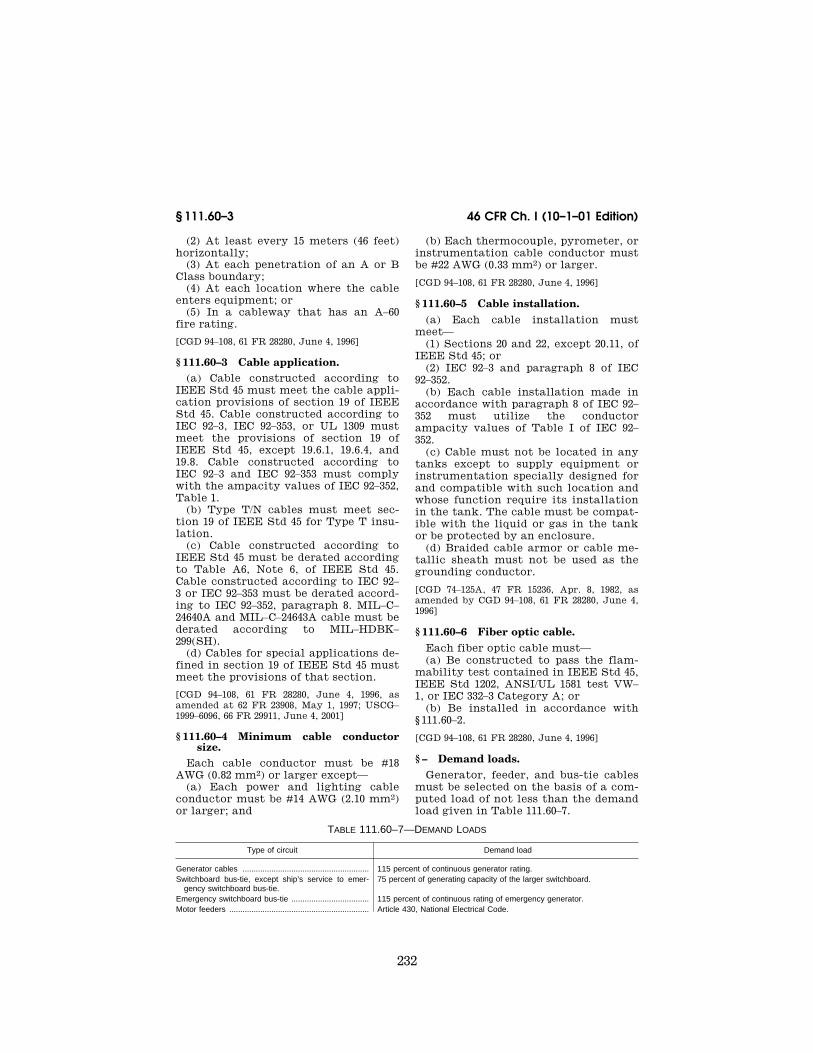
232
46 CFR Ch. I (10–1–01 Edition)§ 111.60–3
(2) At least every 15 meters (46 feet)horizontally;
(3) At each penetration of an A or BClass boundary;
(4) At each location where the cableenters equipment; or
(5) In a cableway that has an A–60fire rating.
[CGD 94–108, 61 FR 28280, June 4, 1996]
§ 111.60–3 Cable application.(a) Cable constructed according to
IEEE Std 45 must meet the cable appli-cation provisions of section 19 of IEEEStd 45. Cable constructed according toIEC 92–3, IEC 92–353, or UL 1309 mustmeet the provisions of section 19 ofIEEE Std 45, except 19.6.1, 19.6.4, and19.8. Cable constructed according toIEC 92–3 and IEC 92–353 must complywith the ampacity values of IEC 92–352,Table 1.
(b) Type T/N cables must meet sec-tion 19 of IEEE Std 45 for Type T insu-lation.
(c) Cable constructed according toIEEE Std 45 must be derated accordingto Table A6, Note 6, of IEEE Std 45.Cable constructed according to IEC 92–3 or IEC 92–353 must be derated accord-ing to IEC 92–352, paragraph 8. MIL–C–24640A and MIL–C–24643A cable must bederated according to MIL–HDBK–299(SH).
(d) Cables for special applications de-fined in section 19 of IEEE Std 45 mustmeet the provisions of that section.
[CGD 94–108, 61 FR 28280, June 4, 1996, asamended at 62 FR 23908, May 1, 1997; USCG–1999–6096, 66 FR 29911, June 4, 2001]
§ 111.60–4 Minimum cable conductorsize.
Each cable conductor must be #18AWG (0.82 mm2) or larger except—
(a) Each power and lighting cableconductor must be #14 AWG (2.10 mm2)or larger; and
(b) Each thermocouple, pyrometer, orinstrumentation cable conductor mustbe #22 AWG (0.33 mm2) or larger.
[CGD 94–108, 61 FR 28280, June 4, 1996]
§ 111.60–5 Cable installation.(a) Each cable installation must
meet—(1) Sections 20 and 22, except 20.11, of
IEEE Std 45; or(2) IEC 92–3 and paragraph 8 of IEC
92–352.(b) Each cable installation made in
accordance with paragraph 8 of IEC 92–352 must utilize the conductorampacity values of Table I of IEC 92–352.
(c) Cable must not be located in anytanks except to supply equipment orinstrumentation specially designed forand compatible with such location andwhose function require its installationin the tank. The cable must be compat-ible with the liquid or gas in the tankor be protected by an enclosure.
(d) Braided cable armor or cable me-tallic sheath must not be used as thegrounding conductor.
[CGD 74–125A, 47 FR 15236, Apr. 8, 1982, asamended by CGD 94–108, 61 FR 28280, June 4,1996]
§ 111.60–6 Fiber optic cable.Each fiber optic cable must—(a) Be constructed to pass the flam-
mability test contained in IEEE Std 45,IEEE Std 1202, ANSI/UL 1581 test VW–1, or IEC 332–3 Category A; or
(b) Be installed in accordance with§ 111.60–2.
[CGD 94–108, 61 FR 28280, June 4, 1996]
§ – Demand loads.Generator, feeder, and bus-tie cables
must be selected on the basis of a com-puted load of not less than the demandload given in Table 111.60–7.
TABLE 111.60–7—DEMAND LOADS
Type of circuit Demand load
Generator cables ......................................................... 115 percent of continuous generator rating.Switchboard bus-tie, except ship’s service to emer-
gency switchboard bus-tie.75 percent of generating capacity of the larger switchboard.
Emergency switchboard bus-tie ................................... 115 percent of continuous rating of emergency generator.Motor feeders ............................................................... Article 430, National Electrical Code.
VerDate 11<MAY>2000 13:58 Oct 22, 2001 Jkt 194182 PO 00000 Frm 00232 Fmt 8010 Sfmt 8010 Y:\SGML\194182T.XXX pfrm04 PsN: 194182T

233
Coast Guard, DOT § 111.60–17
TABLE 111.60–7—DEMAND LOADS—Continued
Type of circuit Demand load
Galley equipment feeder .............................................. 100 percent of either the first 50 KW or one-half the connected load,whichever is the larger, plus 65 percent of the remaining connectedload, plus 50 percent of the rating of the spare switches or circuitbreakers on the distribution panel.
Lighting feeder ............................................................. 100 percent of the connected load plus the average active circuit loadfor the spare switches or circuit breakers on the distribution panels.
Grounded neutral of a dual voltage feeder ................. 100 percent of the capacity of the ungrounded conductors when ground-ed neutral is not protected by a circuit breaker overcurrent trip, or notless than 50 percent of the capacity of the ungrounded conductorswhen the grounded neutral is protected by a circuit breaker overcur-rent trip or overcurrent alarm.
§ 111.60–9 Segregation of vital circuits.
(a) General. A branch circuit thatsupplies equipment vital to the propul-sion, control, or safety of the vesselmust not supply any other equipment.
(b) Passenger vessels. (1) Each pas-senger vessel with firescreen bulkheadsthat form main fire zones must havedistribution systems arranged so thatfire in a main fire zone does not inter-fere with essential services in anothermain fire zone.
(2) Main and emergency feeders pass-ing through a main fire zone must beseparated vertically and horizontallyas much as practicable.
§ 111.60–11 Wire.
(a) Wire must be in an enclosure.(b) Wire must be component insu-
lated.(c) Wire, other than in switchboards,
must meet the requirements in sec-tions 19.6.4 and 19.8 of IEEE Std 45;MIL–W–76D; MIL–W–16878F; UL 44; UL83; or equivalent standard.
(d) Switchboard wire must meet sub-part 111.30 of this part.
(e) Wire must be of the copper strand-ed type.
[CGD 94–108, 61 FR 28281, June 4, 1996, asamended at 62 FR 23908, May 1, 1997; 62 FR27659, May 20, 1997]
§ 111.60–13 Flexible electric cord andcables.
(a) Construction and testing. Eachflexible cord and cable must meet therequirements in section 19.6.1 of IEEEStd 45, article 400 of the NEC, NEMAWC 3, NEMA WC 8, or UL 62.
(b) Application. A flexible cord mustbe used:
(1) Only as allowed under Sections400–7 and 400–8 of the National Elec-trical Code; and
(2) In accordance with Table 400–4 ofthe National Electrical Code.
(c) Allowable current-carrying capacity.A flexible cord must not carry morecurrent than allowed under Table 400–5of the National Electrical Code, NEMAWC 3 or NEMA WC 8.
(d) Conductor size. Each flexible cordmust be No. 18 AWG (0.82 mm2) or larg-er.
(e) Splices. Each flexible cord andcable must be without splices or tapsexcept for a cord or cable No. 12 AWG(3.3 mm2) or larger spliced for repairsin accordance with § 111.60–19.
(f) Pull at joints and terminals. Eachflexible cord and cable must be con-nected to a device or fitting by a knot,tape, or special fitting so that tensionis not transmitted to joints or terminalscrews.
[CGD 74–125A, 47 FR 15236, Apr. 8, 1982, asamended by CGD 94–108, 61 FR 28281, June 4,1996]
§ 111.60–17 Connections and termi-nations.
(a) In general, connections and termi-nations to all conductors must retainthe original electrical, mechanical,flame-retarding, and, where necessary,fire-resisting properties of the cable.All connecting devices must be suit-able for copper stranded conductors.
(b) If twist-on type of connectors areused, the connections must be madewithin an enclosure and the insulatedcap of the connector must be securedto prevent loosening due to vibration.
(c) Twist-on type of connectors maynot be used for making joints in cables,
VerDate 11<MAY>2000 13:58 Oct 22, 2001 Jkt 194182 PO 00000 Frm 00233 Fmt 8010 Sfmt 8010 Y:\SGML\194182T.XXX pfrm04 PsN: 194182T

234
46 CFR Ch. I (10–1–01 Edition)§ 111.60–19
facilitating a conductor splice, or ex-tending the length of a circuit.
[CGD 94–108, 61 FR 28281, June 4, 1996]
§ 111.60–19 Cable splices.(a) A cable must not be spliced in a
hazardous location, except in intrinsi-cally safe systems.
(b) Each cable splice must be made inaccordance with section 20.11 of IEEEStd 45.
[CGD 94–108, 61 FR 28281, June 4, 1996]
§ 111.60–21 Cable insulation tests.All electric power and lighting cable
and associated equipment must bechecked for proper insulation resist-ance to ground and between conduc-tors. The insulation resistance mustnot be less than that in section 46.2.1 ofIEEE Std 45.
[CGD 74–125A, 47 FR 15236, Apr. 8, 1982, asamended by CGD 94–108, 61 FR 28281, June 4,1996]
§ 111.60–23 Metal-clad (Type MC)cable.
(a) Metal-clad (Type MC) cable per-mitted on board a vessel must be con-tinuous corrugated metal-clad cable.
(b) The cable must—(1) Have a corrugated gas-tight,
vapor-tight, and watertight sheath ofaluminum or other suitable metal thatis close-fitting around the conductorsand fillers and that has an overall jack-et of an impervious PVC or thermosetmaterial; and
(2) Be certified or listed by an inde-pendent laboratory as meeting the re-quirements of UL 1569.
(c) The cable is not allowed in areasor applications exposed to high vibra-tion, festooning, repeated flexing, ex-cessive movement, or twisting, such asin engine rooms, on elevators, or in thearea of drill floors, draw works, shak-ers, and mud pits.
(d) The cable must be installed in ac-cordance with article 334 of the NEC.The ampacity values found in table A6of IEEE Std 45 may not be used.
(e) The side wall pressure on thecable must not exceed 1,000 pounds perfoot of radius.
(f) Equipment grounding conductorsin the cable must be sized in accord-ance with article 250–95 of the NEC.
System grounding conductors must beof a cross-sectional area not less thanthat of the normal current carryingconductors of the cable. The metalsheath must be grounded but must notbe used as a required grounding con-ductor.
(g) On an offshore floating drillingand production facility, the cable maybe used as interconnect cable betweenproduction modules and between fixeddistribution panels within the produc-tion modules, except that interconnec-tion between production and tem-porary drilling packages is prohibited.Also, the cable may be used within col-umns, provided that the columns arenot subject to the conditions describedin paragraph (c) of this section.
(h) When the cable is used within ahazardous (classified) location, termi-nations or fittings must be listed, andmust be appropriate, for the particularType MC cable used and for the envi-ronment in which they are installed.
[CGD 94–108, 62 FR 23908, May 1, 1997]
Subpart 111.70—Motor Circuits,Controllers, and Protection
§ 111.70–1 General.
(a) Each motor circuit, controller,and protection must meet the require-ments of ABS Rules for Building andClassing Steel Vessels, sections 4/5A5.13, 4/5B2.13, 4/5B2.15, and 4/5C4; ABSRules for Building and Classing MobileOffshore Drilling Units, sections 4/3.87through 4/3.94 and 4/3.115.6; or IEC 92–301, as appropriate, except the fol-lowing circuits:
(1) Each steering gear motor circuitand protection must meet part 58, sub-part 58.25, of this chapter.
(2) Each propulsion motor circuit andprotection must meet subpart 111.35 ofthis part.
(b) In ungrounded three-phase alter-nating current systems, only twomotor-running protective devices(overload coil or heater type relaywithin the motor and controller) needbe used in any two ungrounded conduc-tors, except when a wye-delta or adelta-wye transformer is used.
VerDate 11<MAY>2000 13:58 Oct 22, 2001 Jkt 194182 PO 00000 Frm 00234 Fmt 8010 Sfmt 8010 Y:\SGML\194182T.XXX pfrm04 PsN: 194182T

235
Coast Guard, DOT § 111.70–7
(c) The motor disconnecting meansmust be an externally operable switchor circuit breaker.
[CGD 74–125A, 47 FR 15236, Apr. 8, 1982, asamended by CGD 94–108, 61 FR 28281, June 4,1996; 62 FR 23909, May 1, 1997]
§ 111.70–3 Motor controllers and motorcontrol centers.
(a) General. The enclosure for eachmotor controller or motor control cen-ter must meet NEMA No. ICS 2 andNEMA No. 2.3 1983 or meet Table 5 ofIEC 92–201, as appropriate, for the loca-tion where it is installed. In addition,each enclosure in a hazardous locationmust meet subpart 111.105 of this part.NEMA No. 2.4 provides guidance on thedifferences between NEMA and IEC de-vices for motor service.
(b) Low-voltage release. Each motorcontroller for a fire pump, elevator,steering gear, or auxiliary that is vitalto the vessel’s propulsion system, ex-cept a motor controller for a vital pro-pulsion auxiliary which can be re-started from a central control station,must have low-voltage release if auto-matic restart after a voltage failure orits resumption to operation is not haz-ardous. If automatic restart is haz-ardous, the motor controller must havelow-voltage protection. Motor control-lers for other motors must not havelow-voltage release unless the startingcurrent and the short-time sustainedcurrent of the additional low-voltagerelease load is within the capacity ofone ship’s service generator. Auto-matic sequential starting of low-volt-age release controllers is acceptable tomeet this paragraph.
(c) Low-voltage protection. Each motorcontroller must have low-voltage pro-tection, except for the following motorcontrollers:
(1) A motor controller that has low-voltage release under paragraph (b) ofthis section.
(2) A motor controller for a motor ofless than 2 horsepower (1.5 kW).
(d) Identification of controllers. (1)Each motor controller and motor con-trol center must be marked externallywith the following information:
(i) Manufacturer’s name or identi-fication.
(ii) Voltage.(iii) Number of phases.
(iv) Current.(v) kW (Horsepower).(vi) Identification of motor being
controlled.(vii) Current rating of trip setting.(2) Each controller must be provided
with heat durable and permanent ele-mentary wiring/schematic diagrams ofthe controller located on the door inte-rior.
[CGD 94–108, 61 FR 28281, June 4, 1996; 61 FR33045, June 26, 1996]
§ 111.70–5 Heater circuits.(a) If an enclosure for a motor, mas-
ter switch, or other equipment has anelectric heater inside the enclosurethat is energized from a separate cir-cuit, the heater circuit must be discon-nected from its source of potential by adisconnect device independent of theenclosure containing the heater. Theheater disconnecting device must beadjacent to the equipment dis-connecting device. A fixed sign, warn-ing the operator to open both devices,must be on the enclosure of the equip-ment disconnect device, except as inparagraph (b) of this section.
(b) If the location of the enclosure fora motor, master switch, or other equip-ment for deck machinery is remotefrom the motor and controller dis-connect device, a sign must be fixed tothe enclosure if the disconnect ar-rangement required by paragraph (a) ofthis section is not used. The sign mustwarn the operator of the presence oftwo sources of potential within the en-closure and show the location of theheater circuit disconnect device.
(c) Electric heaters installed withinmotor controllers and energized from aseparate circuit must be disconnectedin the same manner as required byparagraph (a) of this section or by§ 111.70–7(d).
[CGD 74–125A, 47 FR 15236, Apr. 8, 1982, asamended by CGD 94–108, 61 FR 28282, June 4,1996]
§ 111.70–7 Remote control, interlock,and indicator circuits.
(a) Overcurrent protection. A con-ductor of a control, interlock, or indi-cator circuit of a motor controllermust be protected against overcurrentunless:
VerDate 11<MAY>2000 13:58 Oct 22, 2001 Jkt 194182 PO 00000 Frm 00235 Fmt 8010 Sfmt 8010 Y:\SGML\194182T.XXX pfrm04 PsN: 194182T

236
46 CFR Ch. I (10–1–01 Edition)§ 111.75–1
(1) The conductor is wholly withinthe controller enclosure;
(2) The rating or setting of thebranch circuit overcurrent device isnot more than 300 percent of the cur-rent-carrying capacity of the control,interlock, or indicator circuit con-ductor;
(3) There is an overcurrent device ineach side of the line that has a ratingor setting of not more than 300 percentof the current-carrying capacity of thecontrol, electrical interlock, or indi-cator circuit conductor, except if underoperating conditions there is no appre-ciable difference in potential betweenthe external conductors, overcurrentprotection need only be at the supplyof that side of the line; or
(4) The opening of the control, inter-lock, or indicator circuit creates a haz-ard.
NOTE: For overcurrent protection of steer-ing gear control and indicator circuits, seeSubpart 111.93 of this chapter.
(b) Accidental ground. The controllermust be designed to prevent an acci-dental ground in a remote control cir-cuit from causing the stop switches tofail to operate or causing the motor tostart.
(c) Source of potential. The potentialfor a control, interlock, or indicatorcircuit must be derived from the loadside of the motor and controller dis-connect device, except if the controlfunctions require circuits that must becommon to two or more controllers,the switching arrangement in para-graph (d) of this section must be met.
(d) Switching. In the design of a con-trol, interlock, or indicator circuit, allpracticable steps must be taken toeliminate all but one source of powerin an enclosure. If the control func-tions make it impracticable to energizea control interlock or indicator circuitfrom the load side of a motor and con-troller disconnect device and the volt-age of the control, interlock, or indi-cator circuit is more than 24 volts,there must be one of the following al-ternative methods of switching:
(1) Each conductor of a control,interlock, or indicator circuit must bedisconnected from all sources of poten-tial by a disconnect device independentof the motor and controller disconnectdevice. The two independent devices
must be adjacent to each other, and afixed sign, warning the operator toopen both devices to disconnect com-pletely the motor and controller, mustbe on the exterior of the door of themain disconnect device.
(2) Each conductor of a control,interlock, or indicator circuit must bedisconnected from all sources of powerby a disconnect device actuated by theopening of the controller door, or thepower must first be disconnected toallow opening of the door. The dis-connect device and its connections, in-cluding each terminal block for termi-nating the vessel’s wiring, must haveno electrically uninsulated orunshielded surface. When this type ofdisconnect device is used for vital aux-iliary circuits, a nameplate must be af-fixed to the vital auxiliary motor con-troller door that warns that openingthe door will trip a vital auxiliary off-line.
[CGD 74–125A, 47 FR 15236, Apr. 8, 1982, asamended by CGD 94–108, 61 FR 28282, June 4,1996; 62 FR 23909, May 1, 1997]
Subpart 111.75—Lighting Circuitsand Protection
§ 111.75–1 Lighting feeders.
(a) Passenger vessels. On a passengervessel with fire bulkheads formingmain vertical and horizontal fire zones,the lighting distribution system, in-cluding low location egress lightingwhere installed, must be arranged sothat, to the maximum extent possible,a fire in any main vertical and hori-zontal fire zone does not interfere withthe lighting in any other fire zone.This requirement is met if main andemergency feeders passing through anyzone are separated both vertically andhorizontally as widely as practicable.
(b) Machinery spaces. Lighting forenginerooms, boilerrooms, and auxil-iary machinery spaces must be sup-plied from two or more feeders. One ofthese feeders must be a ship’s servicefeeder.
NOTE: Special requirements for emergencylighting, feeders, and branch circuits are insubpart 112.43 of this chapter.
[CGD 74–125A, 47 FR 15236, Apr. 8, 1982, asamended by CGD 94–108, 61 FR 28282, June 4,1996; 61 FR 33045, June 26, 1996]
VerDate 11<MAY>2000 13:58 Oct 22, 2001 Jkt 194182 PO 00000 Frm 00236 Fmt 8010 Sfmt 8010 Y:\SGML\194182T.XXX pfrm04 PsN: 194182T
237
Coast Guard, DOT § 111.75–17
§ 111.75–5 Lighting branch circuits.
(a) Loads. A lighting distributionpanel must not supply branch circuitsrated at over 30 amperes.
(b) Connected load. The connectedload on a lighting branch circuit mustnot be more than 80 percent of the rat-ing of the overcurrent protective de-vice, computed on the basis of the fix-ture ratings and in accordance withIEEE Std 45, section 21.6.
(c) Lighting fixtures on lighting cir-cuits. Each lighting fixture must be ona lighting branch circuit.
(d) Overcurrent protection. Each light-ing branch circuit must be protectedby an overcurrent device rated at 20amperes or less, except as allowedunder paragraph (e) of this section.
(e) 25 or 30 ampere lighting branch cir-cuits. Lighting branch circuits rated at25 and 30 amperes supplying only fixednonswitched lighting fixtures for cargohold or deck lighting having onlylampholders of the mogul type, orother lampholding devices required forlamps of more than 300 watts, may besupplied by a 30 ampere branch circuitwired with at least No. 10 AWG (5.3mm2) conductors if each fixture wireused in wiring each lighting fixture isNo. 12 AWG (3.3 mm2) or larger.
[CGD 74–125A, 47 FR 15236, Apr. 8, 1982, asamended by CGD 94–108, 61 FR 28282, June 4,1996; 62 FR 23909, May 1, 1997]
§ 111.75–15 Lighting requirements.
(a) Lights in passageways, publicspaces, and berthing compartments. Thesupply to lights in each passageway,public space, or berthing compartmentaccommodating more than 25 personsmust be divided between two or morebranch circuits, one of which may bean emergency branch circuit.
(b) Lights in machinery spaces. Alter-nate groups of lights in an engineroom,boilerroom, or auxiliary machineryspace must be arranged so that thefailure of one branch circuit does notleave an area without light.
(c) Illumination of passenger and crewspaces. (1) Each space used by pas-sengers or crew must be fitted withlighting that provides for a safe habit-able and working environment undernormal conditions.
(2) Sufficient illumination must beprovided by the emergency lightingsource under emergency conditions toeffect damage control procedures andto provide for safe egress from eachspace.
(d) Berth lights. Each crew berth musthave a fixed berth light that is notwired with a flexible cord. The berthlight must have minimum horizontalprojection so that the light may not becovered with bedding.
(e) Exit lights. Each exit light re-quired on passenger vessels under§ 112.15–1 of this subchapter must havethe word ‘‘Exit’’ in red block letters atleast 2 inches (50 mm) high.
(f) Pilot ladders. There must be ameans for lighting each station fromwhich a pilot may be deployed.
[CGD 74–125A, 47 FR 15236, Apr. 8, 1982, asamended by CGD 94–108, 61 FR 28282, June 4,1996]
§ 111.75–16 Lighting of survival craftand rescue boats.
(a) During preparation, launching,and recovery, each survival craft andrescue boat, its launching appliance,and the area of water into which it isto be launched or recovered must beadequately illuminated by lightingsupplied from the emergency powersource.
(b) The arrangement of circuits mustbe such that the lighting for adjacentlaunching stations for survival craft orrescue boats is supplied by differentbranch circuits.
[CGD 94–108, 61 FR 28282, June 4, 1996]
§ 111.75–17 Navigation lights.Each navigation light system must
meet the following:(a) Feeders. On vessels required to
have a final emergency power sourceby § 112.05–5(a) of this chapter, eachnavigation light panel must be suppliedby a feeder from the emergency switch-board (see § 112.43–13). The feeder mustbe protected by overcurrent devicesrated or set at a value of at least twicethat of the navigation light panel mainfuses.
(b) Navigation light indicator panel.Each self-propelled vessel must have anavigation light indicator panel in thenavigating bridge to control side,
VerDate 11<MAY>2000 13:58 Oct 22, 2001 Jkt 194182 PO 00000 Frm 00237 Fmt 8010 Sfmt 8010 Y:\SGML\194182T.XXX pfrm04 PsN: 194182T
238
46 CFR Ch. I (10–1–01 Edition)§ 111.75–18
masthead, and stern lights. The panelmust visually and audibly signal thefailure of each of these navigationlights. Each light source must be con-nected to a separate fused branch cir-cuit. The panel must have a fused feed-er disconnect switch, and the fusesmust have at least twice the rating ofthe largest branch circuit fuse andmust be greater than the maximumpanel load.
(c) Dual light sources. Each self-pro-pelled vessel must have duplicate lightsources for the side, masthead, andstern lights.
(d) Navigation lights. Each navigationlight must meet the following:
(1) Meet the technical details of theapplicable navigation rules.
(2) Be certified by an independentlaboratory to the requirements of UL1104 or an equivalent standard under§ 110.20-1 of this chapter. Portable bat-tery powered lights need meet only therequirements of the standard applica-ble to those lights.
(3) Be labeled with a label stating thefollowing:
(i) ‘‘MEETS lllll.’’ (Insert theidentification name or number of thestandard under paragraph (d)(2) of thissection to which the light was type-tested.)
(ii) ‘‘TESTED BY lllll.’’ (Insertthe name or registered certificationmark of the independent laboratorythat tested the fixture to the standardunder paragraph (d)(2) of this section).
(iii) Manufacturer’s name.(iv) Model number.(v) Visibility of the light in nautical
miles.(vi) Date on which the fixture was
type-tested.(vii) Identification of bulb used in the
compliance test.(4) If it is a flashing light, have its in-
tensity determined by the formula:
Ie=G/(0.2+t2¥t1)
WhereIe=Luminous Intensity.G=Integral of Idt evaluated between
the limits of t1 and t2.t1=Time in seconds of the beginning of
the flash.t2=Time in seconds of the end of the
flash.
I=Instantaneous intensity during theflash.
NOTE: The limits, t1 and t2, are to be cho-sen so as to maximize Ie.
(e) Installation of navigation lights.Each navigation light must:
(1) Be installed so that its locationand its angle of visibility meet the ap-plicable navigation rules;
(2) Except as permitted by the appli-cable navigation rules, be arranged sothat light from a navigation light isnot obstructed by any part of; the ves-sel’s structure or rigging;
(3) Be wired by a short length ofheavy-duty, flexible cable to a water-tight receptacle outlet next to thelight or, for permanently mounted fix-tures, by direct run of fixed cable; and
(4) If it is a double-lens, two-lamptype, have each lamp connected to itsbranch circuit conductors either by anindividual flexible cable and watertightreceptacle plug or, for permanentlymounted fixtures, by an individual di-rect run of fixed cable.
[CGD 74–125A, 47 FR 15236, Apr. 8, 1982, asamended by CGD 94–108, 61 FR 28282, June 4,1996; 61 FR 33045, June 26, 1996; 62 FR 23909,May 1, 1997]
§ 111.75–18 Signaling lights.Each self-propelled vessel over 150
gross tons when engaged on an inter-national voyage must have on board anefficient daylight signaling lamp thatmay not be solely dependent upon thevessel’s main source of electrical powerand that meets the following:
(a) The axial luminous intensity ofthe beam must be at least 60,000 can-delas.
(b) The luminous intensity of thebeam in every direction within anangle of 0.7 degrees from the axial mustbe at least 50 percent of the axial lumi-nous intensity.
[CGD 94–108, 61 FR 28282, June 4, 1996]
§ 111.75–20 Lighting fixtures.(a) The construction of each lighting
fixture for a non-hazardous locationmust meet—
(1) UL 595, until May 3, 1999;(2) UL 1570, UL 1571, or UL 1572, as ap-
plicable, including marine supplement;or
(3) IEC 92–306.
VerDate 11<MAY>2000 13:58 Oct 22, 2001 Jkt 194182 PO 00000 Frm 00238 Fmt 8010 Sfmt 8010 Y:\SGML\194182T.XXX pfrm04 PsN: 194182T
239
Coast Guard, DOT § 111.79–9
(b) Each fixture globe, lens, or dif-fuser must have a high strength guardor be made of high strength material,except in an accommodation space,navigating bridge, gyro room, radioroom, galley, or similar space where itis not subject to damage.
(c) No fixture may be used as a con-nection box for a circuit other than thebranch circuit supplying the fixture.
(d) Lighting fixtures must be in-stalled as follows:
(1) Each fixture in the weather or ina location exposed to splashing watermust be watertight. Each fixture in adamp or wet location must at least bedripproof.
(2) Each fixture and lampholder mustbe fixed. A fixture must not be sup-ported by the screw shell of alampholder.
(3) Each pendent-type fixture must besuspended by and supplied through athreaded, rigid conduit stem.
(4) Each tablelamp, desklamp,floorlamp, and similar equipment mustbe secured in place so that it cannot bedisplaced by the roll or pitch of thevessel.
(e) Non-emergency and decorative in-terior lighting fixtures in environ-mentally-protected, non-hazardous lo-cations need only meet the applicableUL type-fixture standards in UL 1570through 1574 (and either the generalsection of the marine supplement orthe general section of UL 595), UL 595,or IEC 92–306. These fixtures must havevibration clamps on fluorescent tubeslonger than 102 cm (40 inches), securemounting of glassware, and rigidmounting.
[CGD 74–125A, 47 FR 15236, Apr. 8, 1982, asamended by CGD 94–108, 61 FR 28283, June 4,1996; 61 FR 36787, July 12, 1996; 62 FR 23909,May 1, 1997]
Subpart 111.77—Appliances andAppliance Circuits
§ 111.77–1 Overcurrent protection.
If a circuit supplies only one appli-ance or device, the rating or setting ofthe branch circuit overcurrent devicemust not be more than 150 percent ofthe rating of the appliance or device, or15 amperes, whichever is greater.
§ 111.77–3 Appliances.All electrical appliances, including,
but not limited to, cooking equipment,dishwashers, refrigerators, and refrig-erated drinking water coolers, mustmeet UL safety and constructionstandards or equivalent standardsunder § 110.20-1 of this chapter. Also,this equipment must be suitably in-stalled for the location and service in-tended.
[CGD 94–108, 61 FR 28283, June 4, 1996; 61 FR33045, June 26, 1996]
Subpart 111.79—Receptacles
§ 111.79–1 Receptacle outlets; general.(a) There must be a sufficient number
of receptacle outlets in the crew ac-commodations for an adequate level ofhabitability.
(b) There must be a sufficient numberof receptacle outlets throughout themachinery space so that any locationcan be reached by a portable powercord having a length not greater than24 meters (75 feet).
(c) Each receptacle outlet must becompatible with the voltage and cur-rent of the circuit in which it is in-stalled.
(d) Each receptacle outlet must besuitable for the environment in whichit is installed and constructed to theappropriate NEMA or IEC protectionstandard as referenced in § 111.01–9.Special attention must be given to out-lets in hazardous locations.
(e) A receptacle outlet must not haveany exposed live parts with the plugopening uncovered.
[CGD 94–108, 61 FR 28283, June 4, 1996]
§ 111.79–3 Grounding pole.Each receptacle outlet that operates
at 100 volts or more must have agrounding pole.
§ 111.79–9 Transmitting power be-tween receptacles.
(a) If it is necessary to transmit cur-rent in one direction between two re-ceptacle outlets by a flexible cablewith a plug on each end, such as a bat-tery charging lead between a recep-tacle outlet on a ship and a receptacleoutlet in a lifeboat, the plug that may
VerDate 11<MAY>2000 13:58 Oct 22, 2001 Jkt 194182 PO 00000 Frm 00239 Fmt 8010 Sfmt 8010 Y:\SGML\194182T.XXX pfrm04 PsN: 194182T
240
46 CFR Ch. I (10–1–01 Edition)§ 111.79–11
be energized when not in the receptacleoutlet must be female.
(b) If a receptacle outlet may be usedas a source of power and as a receiverof power, such as the receptacles onbarges that may have to supply powerto adjoining barges in some makeupand receive power from the towboat oradjoining barge in other makeups, thereceptacles must be male and reverseservice. Plugs of flexible cable must befemale and must be at both ends of theflexible lead. The female plug mustmeet § 111.79–7.
§ 111.79–11 Lifeboat receptacles.
Each receptacle outlet on a lifeboatfor connection to a vessel’s electricalsystem must allow the plug to pull freewhen the lifeboat is lowered.
§ 111.79–13 Different voltages andpower types.
If receptacle outlets on a vessel aresupplied by different voltages (e.g., 110volts and 220 volts) or by differenttypes of power (e.g., AC and DC), eachreceptacle outlet must preclude theplugging of a portable device into a re-ceptacle outlet of an incompatiblevoltage or type of power.
[CGD 94–108, 61 FR 28283, June 4, 1996]
§ 111.79–15 Receptacles for refrig-erated containers.
Receptacles for refrigerated con-tainers must meet one of the following:
(a) Each receptacle for refrigeratedcontainers must have a switchinterlocked in such a way that the re-ceptacle’s contacts are deenergized be-fore the making or breaking of the con-nection between the plug and recep-tacle contacts.
(b) Each group of receptacles for re-frigerated containers must have:
(1) A switch near the receptacles thatdisconnects all power to those recep-tacles; and
(2) A sign stating that the switchshould be opened before cables are dis-connected from the receptacles or re-frigerated containers.
(c) Each receptacle for refrigeratedcontainers must be designed for circuitbreaking service.
Subpart 111.81—Outlet Boxes andJunction Boxes
§ 111.81–1 Outlet boxes and junctionboxes; general.
(a) The requirements of this subpartapply to each outlet box used with alighting fixture, wiring device, or simi-lar item, including each separately in-stalled connection and junction box.
(b) An outlet box must be at eachoutlet, switch, receptacle, or junctionpoint.
(c) Each outlet or junction box musthave a cover unless a fixture canopy,switch cover, receptacle cover, or othercover is used.
(d) Each outlet box and junction boxinstallation must meet article 370 ofthe NEC, UL 50, UL 514 series, or IECSeries 92 Publications (e.g., IEC 92–306),as appropriate.
(e) Each outlet or junction box mustbe securely attached to its mountingand be affixed so as to maintain its des-ignated degree of protection.
(f) Each outlet and junction box mustbe suitable for the environment inwhich it is installed and be constructedto the appropriate NEMA or IEC stand-ard.
[CGD 74–125A, 47 FR 15236, Apr. 8, 1982, asamended by CGD 94–108, 61 FR 28283, June 4,1996]
§ 111.81–3 Cables entering boxes.
Each cable entering a box or fittingmust be protected from abrasion andmust meet the following:
(a) Each opening through which aconductor enters must be closed.
(b) Cable armor must be secured tothe box or fitting.
(c) Each cable entrance in a damp orwet location must be made watertightby a terminal or stuffing tube.
Subpart 111.83—ShoreConnection Boxes
§ 111.83–1 General.
Each shore connection box must be ofa size that accommodates the connec-tions of the flexible and fixed cables.
VerDate 11<MAY>2000 13:58 Oct 22, 2001 Jkt 194182 PO 00000 Frm 00240 Fmt 8010 Sfmt 8010 Y:\SGML\194182T.XXX pfrm04 PsN: 194182T
241
Coast Guard, DOT § 111.95–1
§ 111.83–5 Bottom entrance and pro-tected enclosures.
Each shore connection box must havea bottom entrance for the shore con-nection cable. The box must provideprotection to the shore connectionwhen the connection is in use.
Subpart 111.85—Electric OilImmersion Heaters
§ 111.85–1 Electric oil immersion heat-ers.
Each oil immersion heater must havethe following:
(a) An operating thermostat.(b) Heating elements that have no
electrical contact with the oil.(c) A high temperature limiting de-
vice that:(1) Opens all conductors to the heat-
er;(2) Is manually reset; and(3) Actuates at a temperature below
the flashpoint of the oil.(d) Either—(1) A low-fluid-level device that opens
all conductors to the heater if the oper-ating level drops below the manufac-turer’s recommended minimum safelevel; or
(2) A flow device that opens all con-ductors to the heater if there is inad-equate flow.
[CGD 74–125A, 47 FR 15236, Apr. 8, 1982, asamended by CGD 94–108, 61 FR 28283, June 4,1996]
Subpart 111.87—Electric AirHeating Equipment
§ 111.87–1 Applicability.This subpart applies to electrically
energized units or panels for heating aroom or compartment. This subpartdoes not apply to electrically energizedunits for heating the air in an enclosedapparatus, such as a motor or con-troller.
§ 111.87–3 General requirements.(a) Each electric heater must meet
UL safety and construction standardsor equivalent standards under § 110.20-1of this chapter.
(b) Each heater element must be anenclosed type. The heater element case
or jacket must be of a corrosion-resist-ant material.
(c) Each heater must have a thermalcutout of the manually-reset type thatprevents overheating and must have athermal regulating switch.
(d) Each heater for bulkhead mount-ing must have its top slanted or other-wise designed to prevent hanging any-thing on the heater. If a heater is port-able, it must have a clip or bracket tohold the heater in a fixed position.
(e) The external temperature of aheater enclosing case must not be over125 degrees C, except that the externaltemperature of the enclosing case of aflush-mounted heater must not be over100 degrees C. If a heater is mounted onor next to a deck or bulkhead, theheater must not cause the temperatureof the nearest deck or bulkhead to beover 55 degrees C. For test purposes, anambient temperature of 25 degrees Cmust be used.
[CGD 74–125A, 47 FR 15236, Apr. 8, 1982, asamended by CGD 94–108, 61 FR 28283, June 4,1996; 61 FR 33045, June 26, 1996; 61 FR 36608,July 11, 1996]
Subpart 111.91—Elevators andDumbwaiters
§ 111.91–1 Power, control, and inter-lock circuits.
Each electric power, control, andinterlock circuit of an elevator ordumbwaiter must meet ANSI/ASMEA17.1 and A17.1A.
[CGD 74–125A, 47 FR 15236, Apr. 8, 1982, asamended by CGD 94–108, 61 FR 28283, June 4,1996]
Subpart 111.95—Electric Power-Operated Boat Winches
§ 111.95–1 Applicability.
(a) The electric installation of eachelectric power-operated boat winchmust meet the requirements in thissubpart, except that limit switchesmust be adapted to the installation ifthere are no gravity davits.
(b) The provisions of this subpartsupplement the requirements for boatwinches in other parts of this chapterunder which vessels are certificated
VerDate 11<MAY>2000 13:58 Oct 22, 2001 Jkt 194182 PO 00000 Frm 00241 Fmt 8010 Sfmt 8010 Y:\SGML\194182T.XXX pfrm04 PsN: 194182T

242
46 CFR Ch. I (10–1–01 Edition)§ 111.95–3
and in subchapter Q, Equipment ap-provals.
[CGD 74–125A, 47 FR 15236, Apr. 8, 1982, asamended by CGD 94–108, 61 FR 28283, June 4,1996]
§ 111.95–3 General requirements.(a) Each electrical component (e.g.,
enclosure, motor controller, or motor)must be constructed to the appropriateNEMA or IEC degree of protection re-quirement for the service and environ-ment in which it is installed.
(b) Each main line emergency dis-connect switch, if accessible to an un-authorized person, must have a meansto lock the switch in the open-circuitposition with a padlock or its equiva-lent. The switch must not lock in theclosed-circuit position.
[CGD 94–108, 61 FR 28283, June 4, 1996]
§ 111.95–7 Wiring of boat winch compo-nents.
(a) If the motor controller of a boatwinch power unit is next to the winch,the main line emergency switch mustdisconnect all parts of the boat winchpower unit, including the motor con-troller and limit switches, from allsources of potential. Other power cir-cuit switches must be connected in se-ries with the main line emergencyswitch and must be ahead of the motorcontroller. The main line emergencyswitch must be the motor and con-troller disconnect required by Subpart111.70 and must have a horsepower rat-ing of at least that of the winch motor.
(b) If the motor controller of a boatwinch power unit is remote from thewinch, there must be a switch at thecontroller that can disconnect the en-tire winch electric installation from allsources of potential. The switch mustbe in series with and on the supply sideof the main line emergency switch.
(c) Each davit arm limit switch,whether connected in the power circuitor in the control circuit, must dis-connect all ungrounded conductors ofthe circuit controlled.
(d) If one motor is used with twowinches, there must be a main lineemergency switch, a clutch interlockswitch, and a master switch for eachwinch, except that a single main lineemergency switch located as required
by paragraph (e) of this section may beused for both winches. The main lineemergency switches must be con-nected, in series, ahead of the motorcontroller. The master switches mustbe connected in parallel and each, inseries, with the corresponding clutchinterlock switch for that winch. Eachclutch interlock switch must open thecircuit to its master switch, exceptwhen the power unit is clutched to theassociated winch. There must be ameans to prevent the power unit frombeing clutched to both winches simul-taneously.
(e) The main line emergency dis-connect switch must be adjacent to themaster switch, within reach of thewinch operator, accessible to the per-son in charge of the boat stowage, andfor gravity davit installations, in a po-sition from which the movement ofboat davit arms can be observed asthey approach the final stowed posi-tion.
[CGD 74–125A, 47 FR 15236, Apr. 8, 1982, asamended by CGD 94–108, 61 FR 28283, June 4,1996]
Subpart 111.97—Electric Power-Operated Watertight Door Systems
§ 111.97–1 Applicability.
This subpart applies to electricpower-operated watertight door sys-tems required under Subpart H of Part170 of this chapter.
[CGD 79–023, 48 FR 51008, Nov. 4, 1983]
§ 111.97–3 General requirements.
Each watertight door operating sys-tem must meet Subpart H, § 170.270 ofthis chapter.
[CGD 74–125A, 47 FR 15236, Apr. 8, 1982, asamended by USCG–2000–7790, 65 FR 58462,Sept. 29, 2000]
§ 111.97–5 Electric and hydraulicpower supply.
(a) Each electric motor-driven dooroperating system must have the samesource of power as the emergencylighting and power system.
(b) The temporary emergency powersource and the final emergency power
VerDate 11<MAY>2000 13:58 Oct 22, 2001 Jkt 194182 PO 00000 Frm 00242 Fmt 8010 Sfmt 8010 Y:\SGML\194182T.XXX pfrm04 PsN: 194182T
243
Coast Guard, DOT § 111.101–1
source must each be capable of oper-ating all doors simultaneously or se-quentially as allowed by § 170.270(c) ofthis chapter.
(c) The power supply for each hydrau-lically operated watertight door sys-tem that uses a hydraulic system com-mon to more than one watertight doormust be an accumulator tank withenough capacity to open all doors onceand to close all doors two times and besupplied by one or more motor-drivenhydraulic pumps that can operate fromthe final source of the emergencylighting and power system.
(d) The motor-driven hydraulicpumps must automatically maintainthe accumulator tank pressure withinthe design limits, be above the upper-most continuous deck, and be con-trolled from above the uppermost con-tinuous deck.
(e) The accumulator tank capacityrequired in paragraph (c) of this sec-tion must be available when the accu-mulator tank pressure is at the auto-matic pump ‘‘cut-in’’ pressure.
(f) The source of power for each hy-draulically operated watertight doorsystem using an independent hydraulicsystem for each door operator mustmeet paragraphs (a) and (b) of this sec-tion.
(g) The power supply for other typesof watertight door operators must beaccepted by the Commandant.
[CGD 74–125A, 47 FR 15236, Apr. 8, 1982, asamended by CGD 94–108, 61 FR 28283, June 4,1996; USCG–2000–7790, 65 FR 58462, Sept. 29,2000]
§ 111.97–7 Distribution.
(a) Each distribution panelboard for awatertight door system must be abovethe uppermost continuous deck andmust have means for locking.
(b) Each feeder supplying a water-tight door operating system must beabove the uppermost continuous deck.
(c) Each watertight door operatingsystem must have a separate branchcircuit.
§ 111.97–9 Overcurrent protection.
Overcurrent devices must be ar-ranged to isolate a fault with as littledisruption of the system as possible.The relationship between the load and
the rating or setting of overcurrent de-vices must meet the following:
(a) The rating or setting of each feed-er overcurrent device must be not lessthan 200 percent of its maximum load.
(b) The rating or setting of a branchcircuit overcurrent device must be notmore than 25 percent of that of thefeeder overcurrent device.
Subpart 111.99—Fire Door Holdingand Release Systems
§ 111.99–1 Applicability.
This subpart applies to fire doorholding and release systems, if fitted.
[CGD 74–125A, 47 FR 15236, Apr. 8, 1982, asamended by CGD 94–108, 61 FR 28284, June 4,1996]
§ 111.99–3 Definitions.
As used in this subpart—Central control panel means a manu-
ally-operated device on the navigatingbridge or in the fire control room forreleasing one or more fire doors.
Fire door means a door that is in afire boundary, such as a stairway en-closure or main vertical zone bulkhead,that is not usually kept closed.
Fire door holding magnet means anelectromagnet for holding a fire dooropen.
Local control panel means a manually-operated device next to a fire door forreleasing the door so that the fire doorself-closing mechanism may close thedoor.
[CGD 94–108, 61 FR 28284, June 4, 1996; 61 FR33045, June 26, 1996]
§ 111.99–5 General.
Fire door release systems, if in-stalled, must meet SOLAS 74, regula-tion II–2/30.4.3.
[CGD 94–108, 61 FR 28284, June 4, 1996]
Subpart 111.101—SubmersibleMotor-Driven Bilge Pumps
§ 111.101–1 Applicability.
This subpart applies to each submers-ible motor-driven bilge pump requiredon certain vessels under § 56.50–55(a)(2)(i) of this chapter.
VerDate 11<MAY>2000 13:58 Oct 22, 2001 Jkt 194182 PO 00000 Frm 00243 Fmt 8010 Sfmt 8010 Y:\SGML\194182T.XXX pfrm04 PsN: 194182T

244
46 CFR Ch. I (10–1–01 Edition)§ 111.101–3
§ 111.101–3 General requirements.(a) Each electric motor driving a sub-
mersible bilge pump must be in an openend air bell of rugged construction andbe of a size that does not allow waterto enter the motor if the compartmentthat the motor is in is flooded to theuppermost continuous deck.
(b) The motor, if of the open type,must be protected from splashingwater from the bottom.
(c) The cable to each motor mustenter through the open bottom of theair bell.
(d) Each motor must be able to oper-ate continuously at rated load underany condition, dry or with water in theair bell at any level up to the max-imum allowed under paragraph (a) ofthis section.
(e) Each motor controller must beabove the uppermost continuous deck.There must be a master switch at thecontroller and a master switch at themotor. The master switch at the motormust be disconnected from the circuitwhen the motor is started or stoppedfrom the master switch at the con-troller.
(f) Each motor must be energizedfrom the final emergency power source.
Subpart 111.103—RemoteStopping Systems
§ 111.103–1 Power ventilation systemsexcept machinery space ventilationsystems.
Each power ventilation system musthave:
(a) A control to stop the ventilationthat is:
(1) Outside the space ventilated; and(2) Grouped with the controls for
every power ventilation system towhich this section is applicable; and
(b) In addition to the control re-quired by paragraph (a), a stop controlthat is:
(1) As far as practicable from the con-trol required by paragraph (a) andgrouped with the controls for everypower ventilation system to which thissection is applicable; or
(2) The circuit breakers for ventila-tion grouped on the main switchboardand marked, ‘‘In Case of Fire Trip toStop Ventilation.’’
NOTE: The requirements of this section donot apply to closed ventilation systems formotors or generators, diffuser fans for refrig-erated spaces, room circulating fans, or ex-haust fans for private toilets of an electricalrating comparable to that of a room circu-lating fan.
§ 111.103–3 Machinery space ventila-tion.
(a) Each machinery space ventilationsystem must have two controls to stopthe ventilation, one of which may bethe supply circuit breaker.
(b) The controls required in para-graph (a) of this section must begrouped so that they are operable fromtwo positions, one of which must beoutside the machinery space.
§ 111.103–7 Ventilation stop stations.
Each ventilation stop station must:(a) Be protected by an enclosure with
a glass-paneled door on the front;(b) Be marked, ‘‘In Case of Fire
Break Glass and Operate Switch toStop Ventilation;’’
(c) Have the ‘‘stop’’ position of theswitch clearly identified;
(d) Have a nameplate that identifiesthe system controlled; and
(e) Be arranged so that damage to theswitch or cable automatically stops theequipment controlled.
§ 111.103–9 Machinery stop stations.(a) Each forced draft fan, induced
draft fan, blower of an inert gas sys-tem, fuel oil transfer pump, fuel oilunit, fuel oil service pump, and anyother fuel oil pumps must have a stopcontrol that is outside of the spacecontaining the pump or fan.
(b) Each stop control must meet§ 111.103–7.
Subpart 111.105—HazardousLocations
§ 111.105–1 Applicability.This subpart applies to installations
in hazardous locations as defined in theNEC and in IEC 79–0.
NOTE TO § 111.105–1: Chemicals and mate-rials in addition to those listed in Table 500–2 of the NEC and IEC 79–12 are listed in sub-chapter O of this chapter.
[CGD 94–108, 61 FR 28284, June 4, 1996]
VerDate 11<MAY>2000 13:58 Oct 22, 2001 Jkt 194182 PO 00000 Frm 00244 Fmt 8010 Sfmt 8010 Y:\SGML\194182T.XXX pfrm04 PsN: 194182T

245
Coast Guard, DOT § 111.105–15
§ 111.105–3 General requirements.
All electrical installations in haz-ardous locations must comply with thegeneral requirements of section 43 ofIEEE Std 45 and either the NEC arti-cles 500–505 or IEC series 79 publica-tions. When installations are made inaccordance with the NEC articles, ma-rine shipboard cable that complies withsubpart 111.60 of this chapter may beused instead of rigid metal conduit, ifinstalled fittings are approved for thespecific hazardous location and thecable type.
[CGD 94–108, 61 FR 28284, June 4, 1996]
§ 111.105–5 System integrity.
In order to maintain system integ-rity, each individual electrical instal-lation in a hazardous location mustcomply specifically with NEC articles500–505, as modified by § 111.105–3, orIEC series 79 publications, but not incombination in a manner that wouldcompromise system integrity or safety.Hazardous location equipment must beapproved as suitable for use in the spe-cific hazardous atmosphere in which itis installed. The use of non-approvedequipment is prohibited.
[CGD 94–108, 61 FR 28284, June 4, 1996]
§ 111.105–7 Approved equipment.
When this subpart or the NEC statesthat an item of electrical equipmentmust be approved or when IEC 79–0states that an item of electrical equip-ment must be tested or approved inorder to comply with IEC 79 series pub-lications, that item must be—
(a) Listed or certified by an inde-pendent laboratory as approved for usein the hazardous locations in which itis installed; or
(b) Purged and pressurized equipmentthat meets NFPA No. 496 or IEC 79–2.
[CGD 94–108, 61 FR 28284, June 4, 1996]
§ 111.105–9 Explosionproof and flame-proof equipment.
Each item of electrical equipmentthat is required in this subpart to beexplosionproof under the NEC classi-fication system must be approved asmeeting UL 1203. Each item of elec-trical equipment that is required in
this subpart to be flameproof must beapproved as meeting IEC 79–1.
[CGD 94–108, 61 FR 28284, June 4, 1996]
§ 111.105–11 Intrinsically safe systems.
(a) Each system required under thissubpart to be intrinsically safe mustuse approved components meeting UL913 or IEC 79–11(Ia).
(b) Each electric cable of an intrinsi-cally safe system must—
(1) Be 50 mm (2 inches) or more fromcable of non-intrinsically safe circuits,partitioned by a grounded metal bar-rier from other non-intrinsically safeelectric cables, or a shielded or metal-lic armored cable; and
(2) Not contain conductors for non-intrinsically safe systems.
(c) As part of plan approval, the man-ufacturer must provide appropriate in-stallation instructions and restrictionson approved system components. Typ-ical instructions and restrictions in-clude information addressing—
(1) Voltage limitations;(2) Allowable cable parameters;(3) Maximum length of cable per-
mitted;(4) Ability of system to accept pas-
sive devices;(5) Acceptability of interconnections
with conductors or other equipment forother intrinsically safe circuits; and
(6) Information regarding any in-structions or restrictions which were acondition of approval of the system orits components.
(d) Each intrinsically safe systemmust meet ISA RP 12.6, except Appen-dix A.1.
[CGD 94–108, 61 FR 28284, June 4, 1996, asamended at 62 FR 23909, May 1, 1997]
§ 111.105–15 Additional methods ofprotection.
Each item of electrical equipmentthat is—
(a) A sand-filled apparatus must meetIEC 79–5;
(b) An oil-immersed apparatus mustmeet either IEC 79–6 or NEC article500–2;
(c) Type of protection ‘‘e’’ must meetIEC 79–7;
(d) Type of protection ‘‘n’’ must meetIEC 79–15; and
VerDate 11<MAY>2000 13:58 Oct 22, 2001 Jkt 194182 PO 00000 Frm 00245 Fmt 8010 Sfmt 8010 Y:\SGML\194182T.XXX pfrm04 PsN: 194182T

246
46 CFR Ch. I (10–1–01 Edition)§ 111.105–17
(e) Type of protection ‘‘m’’ mustmeet IEC 79–18.
[CGD 94–108, 61 FR 28284, June 4, 1996]
§ 111.105–17 Wiring methods for haz-ardous locations.
(a) Through runs of marine shipboardcable meeting subpart 111.60 of thispart are required for all hazardous lo-cations. Armored cable may be used toenhance ground detection capabilities.Additionally, Type MC cable may beused subject to the restrictions in§ 111.60–23.
(b) Where conduit is installed, the ap-plicable requirements of either theNEC or IEC 79 must be followed.
(c) Each cable entrance intoexplosionproof or flameproof equip-ment must be made with approved sealfittings, termination fittings, or glandsthat meet the requirements of § 111.105–9.
(d) Each cable entrance into Class IIand Class III (Zone 10, 11, Z, or Y)equipment must be made with dust-tight cable entrance seals approved forthe installation.
[CGD 94–108, 61 FR 28284, June 4, 1996, asamended at 62 FR 23909, May 1, 1997]
§ 111.105–19 Switches.
A switch that is explosionproof orflameproof, or that controls anyexplosionproof or flameproof equip-ment, under § 111.105–19 must have apole for each ungrounded conductor.
[CGD 94–108, 61 FR 28284, June 4, 1996]
§ 111.105–21 Ventilation.
A ventilation duct which ventilates ahazardous location has the classifica-tion of that location. Each fan for ven-tilation of a hazardous location mustbe nonsparking.
[CGD 94–108, 61 FR 28285, June 4, 1996]
§ 111.105–27 Belt drives.
Each belt drive in a hazardous loca-tion must have:
(a) A conductive belt; and(b) Pulleys, shafts, and driving equip-
ment grounded to meet NFPA No. 77.
§ 111.105–29 Combustible liquid cargocarriers.
(a) Each vessel that carries combus-tible liquid cargo with a closed-cupflashpoint of 60 degrees C (140 degreesF) or higher must have:
(1) Only intrinsically safe electricsystems in cargo tanks; and
(2) No storage battery in any cargohandling room.
(b) If a submerged cargo pump motoris in a cargo tank, it must meet the re-quirements of § 111.105–31(d).
(c) Where the cargo is heated to with-in 15°C of its flashpoint, the cargopumproom must meet the require-ments of § 111.105–31(f) and the weatherlocations must meet § 111.105–31(l).
[CGD 74–125A, 47 FR 15236, Apr. 8, 1982, asamended by CGD 94–108, 61 FR 28285, June 4,1996; 61 FR 36787, July 12, 1996; 61 FR 39695,July 30, 1996]
§ 111.105–31 Flammable or combustiblecargo with a flashpoint below 60 de-grees C (140 degrees F), liquid sul-phur carriers and inorganic acidcarriers.
(a) Applicability. Each vessel that car-ries combustible or flammable cargowith a closed-cup flashpoint lower than60 degrees C (140 degrees F) or liquidsulphur cargo, or inorganic acid cargomust meet the requirements of thissection, except—
(1) A vessel carrying bulk liquefiedflammable gases as a cargo, cargo res-idue, or vapor which must meet the re-quirements of § 111.105–32; and
(2) A vessel carrying carbon disulfidemust have only intrinsically safe elec-tric equipment in the locations listedin paragraphs (e) through (l) of thissection.
(b) Cable location. Electric cable mustbe as close as practicable to the center-line and must be away from cargo tankopenings.
(c) Lighting circuits. An enclosed haz-ardous space that has explosionprooflighting fixtures must:
(1) Have at least two lighting branchcircuits;
(2) Be arranged so that there is lightfor relamping any deenergized lightingcircuit; and
(3) Not have the switch within thespace for those spaces containingexplosionproof lighting fixtures under
VerDate 11<MAY>2000 13:58 Oct 22, 2001 Jkt 194182 PO 00000 Frm 00246 Fmt 8010 Sfmt 8010 Y:\SGML\194182T.XXX pfrm04 PsN: 194182T

247
Coast Guard, DOT § 111.105–31
paragraphs (g), (i) and (j) of this sec-tion.
(d) Submerged cargo pump motors. If asubmerged cargo pump motor is in acargo tank:
(1) Low liquid level, motor current,or pump discharge pressure must auto-matically shutdown power to themotor if the pump loses suction;
(2) An audible and visual alarm mustbe actuated by the shutdown of themotor; and
(3) There must be a lockable circuitbreaker or lockable switch that dis-connects power to the motor.
(e) Cargo tanks. A cargo tank is aClass I, Division 1 (IEC Zone 0) locationwhich has additional electrical equip-ment restrictions outlined in IEEE Std45 and IEC 92–502. Cargo tanks mustnot contain any electrical equipmentexcept the following:
(1) Intrinsically safe equipment.(2) Submerged cargo pump motors
and their associated cable.(f) Cargo handling rooms. A cargo han-
dling room must not have any electriccable or other electric equipment, ex-cept:
(1) Intrinsically safe equipment;(2) Explosionproof lighting fixtures;(3) Cables supplying intrinsically safe
equipment in the cargo handling room;and
(4) Marine shipboard cables that sup-ply explosionproof lighting fixturesthat are in the cargo handling room.
(g) Lighting of cargo handling rooms.Lighting for a cargo handling room ex-cept a cargo handling room under para-graph (h) of this section, must be light-ed through fixed glass lenses in thebulkhead or overhead. Each fixed glasslens must be wire-inserted glass that isat least .025 inches (6.35 mm) thick andarranged to maintain the watertightand gastight integrity of the structure.The fixed glass lens may form a part ofa listing fixture if the following aremet:
(1) There is no access to the interiorof the fixture from the cargo handlingroom.
(2) The fixture is vented to theengineroom or a similar nonhazardousarea.
(3) The fixture is wired from outsidethe cargo handling room.
(4) The temperature on the cargohandling room surface of the glass lens,based on an ambient temperature of 40degrees C, is not higher than 180 de-grees C.
(h) A cargo handling room which pre-cludes the lighting arrangement ofparagraph (g) of this section, or wherethe lighting arrangement of paragraph(g) of the section does not give the re-quired light, must have explosionprooflighting fixtures.
(i) Enclosed spaces. An enclosed spacethat is immediately above, below, ornext to a cargo tank must not containany electric equipment except equip-ment allowed for cargo handling roomsin paragraphs (f) and (g), and:
(1) Through runs of marine shipboardcable; and
(2) Watertight enclosures with boltedand gasketed covers containing only:
(i) Depth sounding devices;(ii) Log devices; and(iii) Impressed-current cathodic pro-
tection system electrodes.(j) Cargo hose stowage space. A cargo
hose stowage space must not have anyelectrical equipment exceptexplosionproof lighting fixtures andthrough runs of marine shipboardcable.
(k) Cargo piping in a space. A spacethat has cargo piping must not haveany electrical equipment exceptexplosionproof lighting fixtures andthrough runs of marine shipboardcable.
(l) Weather locations. The followinglocations in the weather are Class I,Division 1 (Zone 1) locations (exceptthe open deck area on an inorganicacid carrier which is considered a non-hazardous location) and may have onlyapproved intrinsically safe,explosionproof, or purged and pressur-ized electrical equipment, and throughruns of marine shipboard cable if thelocation is—
(1) Within 10 feet (3 m) of:(i) A cargo tank vent outlet;(ii) A cargo tank ullage opening;(iii) A cargo pipe flange;(iv) A cargo valve;(v) A cargo handling room entrance;
or(vi) A cargo handling room ventila-
tion opening; or
VerDate 11<MAY>2000 13:58 Oct 22, 2001 Jkt 194182 PO 00000 Frm 00247 Fmt 8010 Sfmt 8010 Y:\SGML\194182T.XXX pfrm04 PsN: 194182T

248
46 CFR Ch. I (10–1–01 Edition)§ 111.105–32
(2) On a tankship and on the opendeck over the cargo area and 10 feet (3m) forward and aft of the cargo area onthe open deck and up to 8 feet (2.4 m)above the deck.
(3) Within 5 meters (16 ft) of cargopressure/vacuum valves with an unlim-ited height; or
(4) Within 10 meters (33 ft) of ventoutlets for free flow of vapor mixturesand high velocity vent outlets for thepassage of large amounts of vapor, airor inert gas mixtures during cargoloading and ballasting or during dis-charging.
(m) Other spaces. Except for thosespaces listed in paragraphs (e) through(k), a space that has a direct openingto any space listed in paragraphs (e)through (l) must have only the electricinstallations that are allowed for thespace to which it opens.
(n) Duct keel ventilation or lighting. (1)The lighting and ventilation system foreach pipe tunnel, double bottom, orduct keel must meet ABS Rules forBuilding and Classing Steel Vessels,section 4/5E1.15.
(2) If a fixed gas detection system isinstalled, it must meet the require-ments of SOLAS 74 and ABS Rules forBuilding and Classing Steel Vessels,section 4/5.
[CGD 74–125A, 47 FR 15236, Apr. 8, 1982, asamended by CGD 82–096, 49 FR 4947, Feb. 9,1984; CGD 94–108, 61 FR 28285, June 4, 1996; 61FR 33045, June 26, 1996; 62 FR 23909, May 1,1997]
§ 111.105–32 Bulk liquefied flammablegas and ammonia carriers.
(a) Each vessel that carries bulk liq-uefied flammable gases or ammonia asa cargo, cargo residue, or vapor mustmeet the requirements of this section.
(b) As used in this section:(1) The terms ‘‘gas-safe’’ and ‘‘gas-
dangerous’’ spaces are used as definedin § 154.7 of this chapter.
(2) The term ‘‘gas-dangerous’’ doesnot include the weather deck of an am-monia carrier.
(c) Each submerged cargo pumpmotor design must receive concept ap-proval by the Commandant (G–MSE)and its installation must receive planapproval by the Commanding Officer,Marine Safety Center.
(d) Electrical equipment must not beinstalled in a gas-dangerous space orzone, except:
(1) Intrinsically safe electrical equip-ment and wiring, and
(2) Other equipment as allowed inthis section.
(e) A submerged cargo pump motor, ifinstalled in a cargo tank, must meet§ 111.105–31(d).
(f) Electrical equipment must not beinstalled in a hold space that has atank that is not required to have a sec-ondary barrier under § 154.459 of thischapter, except:
(1) Through runs of marine shipboardcable;
(2) Explosionproof lighting fixtures;(3) Depth sounding devices in gas-
tight enclosures;(4) Log devices in gastight enclo-
sures;(5) Impressed current cathodic pro-
tection system electrodes in gastightenclosures; and
(6) Armored or MI type cable for asubmerged cargo pump motor.
(g) Electrical equipment must not beinstalled in a space that is separatedby a gastight steel boundary from ahold space that has a tank that musthave a secondary barrier under the re-quirements of § 154.459 of this chapter,except:
(1) Through runs of marine shipboardcable;
(2) Explosionproof lighting fixtures;(3) Depth sounding devices in gas-
tight enclosures;(4) Log devices in gastight enclo-
sures;(5) Impressed current cathodic pro-
tection system electrodes in gastightenclosures;
(6) Explosionproof motors that oper-ate cargo system valves or ballast sys-tem valves;
(7) Explosionproof bells for generalalarm systems; and
(8) Armored or MI type cable for asubmerged cargo pump motor.
(h) A cargo-handling room must nothave any installed electrical equip-ment, except explosionproof lightingfixtures.
(i) A space for cargo hose storage ora space that has cargo piping must nothave any installed electrical equip-ment, except:
VerDate 11<MAY>2000 13:58 Oct 22, 2001 Jkt 194182 PO 00000 Frm 00248 Fmt 8010 Sfmt 8010 Y:\SGML\194182T.XXX pfrm04 PsN: 194182T

249
Coast Guard, DOT § 111.105–33
(1) Explosionproof lighting fixtures;and
(2) Through runs of marine shipboardcable.
(j) A gas dangerous zone on the opendeck must not have any installed elec-trical equipment, except:
(1) Explosionproof equipment that isnecessary for the operation of the ves-sel; and
(2) Through runs of marine shipboardcable.
(k) A space, except those named inparagraphs (f) through (i) of this sec-tion, that has a direct opening to gas-dangerous spaces or zones must haveno electrical equipment except as al-lowed in the gas-dangerous space orzone.
(l) Each gas-dangerous space that haslighting fixtures must have at leasttwo branch circuits for lighting.
(m) Each switch and each overcur-rent protective device for any lightingcircuit that is in a gas-dangerous spacemust open all conductors of the circuitsimultaneously.
(n) Each switch and each overcurrentprotective device for lighting in a gas-dangerous space must be in a gas-safespace.
[CGD 74–125A, 47 FR 15236, Apr. 8, 1982, asamended by CGD 77–069, 52 FR 31626, Aug. 21,1987; CGD 94–108, 61 FR 28285, June 4, 1996; 62FR 23909, May 1, 1997]
§ 111.105–33 Mobile offshore drillingunits.
(a) Applicability. This section appliesto each mobile offshore drilling unit.
(b) Definitions. As used in this sec-tion:
(1) ‘‘Enclosed spaces’’ are locationsdelineated by floors, bulkheads, ordecks which may have doors or win-dows.
(2) ‘‘Semi-enclosed spaces’’ are loca-tions where natural conditions of ven-tilation are notably different fromthose on open deck due to the presenceof structures such as roofs, windbreaks,and bulkheads which are so arrangedthat dispersion of gas may not occur.
(c) The internal space of each pres-sure vessel, tank, and pipe for drillingmud and for gas venting must haveonly intrinsically safe electric equip-ment.
(d) The following are Class I, Division1 locations:
(1) An enclosed space that containsany part of the mud circulating systemthat has an opening into the space andis between the well and final degassingdischarge.
(2) An enclosed or semi-enclosed loca-tion that is below the drill floor andcontains a possible source of gas re-lease such as the top of a drilling nip-ple.
(3) An enclosed space that is on thedrill floor and is not separated by asolid, gas-tight floor from the spacesspecified in paragraph (d)(2) of this sec-tion.
(4) A space that would normally beconsidered a Division 2 location underparagraph (e) of this section but wherecombustible or flammable gases mightaccumulate. This could include pits,ducts, and similar structures down-stream of the final degassing discharge.
(5) A location in the weather or asemi-enclosed location, except as pro-vided in paragraph (d)(2) of this sec-tion, that is within 5 feet (1.5 m) of theboundary of any:
(i) Equipment or opening specified inparagraph (d)(1) of this section;
(ii) Ventilation outlet, access, orother opening to a Class I, Division 1space; or
(iii) Gas vent outlet.(6) Except as provided in paragraph
(f) of this section, an enclosed spacethat has an opening into a Class I, Di-vision 1 location.
(e) The following are Class I, Division2 locations:
(1) An enclosed space that has anyopen portion of the mud circulatingsystem from the final degassing dis-charge to the mud suction connectionat the mud pit.
(2) A location in the weather that is:(i) Within the boundaries of the drill-
ing derrick up to a height of 10 feet(3m) above the drill floor;
(ii) Below the drill floor and within aradius of 10 feet (3m) of a possiblesource of release, such as the top of adrilling nipple; or
(iii) Within 5 feet (1.5m) of the bound-aries of any ventilation outlet, access,or other opening to a Class I, Division2 space.
(3) A location that is:
VerDate 11<MAY>2000 13:58 Oct 22, 2001 Jkt 194182 PO 00000 Frm 00249 Fmt 8010 Sfmt 8010 Y:\SGML\194182T.XXX pfrm04 PsN: 194182T
250
46 CFR Ch. I (10–1–01 Edition)§ 111.105–35
(i) Within 5 feet (1.5m) of a semi-en-closed Class I, Division 1 location indi-cated in paragraph (d)(2) of this sec-tion; or
(ii) Within 5 feet (1.5m) of a Class I,Division 1 space indicated in paragraph(d)(5).
(4) A semi-enclosed area that is belowand contiguous with the drill floor tothe boundaries of the derrick or to theextent of any enclosure which is liableto trap gases.
(5) A semi-enclosed derrick to the ex-tent of its enclosure above the drillfloor, or to a height of 10 feet (3m)above the drill floor, whichever isgreater.
(6) Except as provided in paragraph(f) of this section, an enclosed spacethat has an opening into a Class I, Di-vision 2 location.
(f) An enclosed space that has directaccess to a Division 1 or Division 2 lo-cation is the same division as that lo-cation, except:
(1) An enclosed space that has directaccess to a Division 1 location is not ahazardous location if:
(i) The access has self-closing gas-tight doors that form an air lock;
(ii) The ventilation causes greaterpressure in the space than in the Divi-sion 1 location; and
(iii) Loss of ventilation overpressureis alarmed at a manned station;
(2) An enclosed space that has directaccess to a Division 1 location can beconsidered as a Division 2 location if:
(i) The access has a self-closing, gas-tight door that opens into the spaceand that has no hold-back device;
(ii) Ventilation causes the air to flowwith the door open from the space intothe Division 1 location; and
(iii) Loss of ventilation is alarmed ata manned control station; and
(3) An enclosed space that has directaccess to a Division 2 location is not ahazardous location if:
(i) The access has a self-closing, gas-tight door that opens into the spaceand that has no hold-back device;
(ii) Ventilation causes the air to flowwith the door open from the space intothe Division 2 location; and
(iii) Loss of ventilation actuates analarm at a manned control station.
(g) Electrical equipment and devicesinstalled in spaces made non-hazardous
by the methods indicated in paragraph(f) of this section must be limited toessential equipment.
§ 111.105–35 Vessels carrying coal.
(a) The following are Class II, Divi-sion 1, (Zone 10 or Z) locations on avessel that carries coal:
(1) The interior of each coal bin andhold.
(2) Each compartment that has a coaltransfer point where coal is trans-ferred, dropped, or dumped.
(3) Each open area within 3 meters (10ft) of a coal transfer point where coal isdropped or dumped.
(b) Each space that has a coal con-veyer on a vessel that carries coal is aClass II, Division 2, (Zone 11 or Y)space.
(c) A space that has a coal conveyeron a vessel that carries coal must haveelectrical equipment approved for ClassII, Division 2, (Zone 11 or Y) hazardouslocations, except watertight generalemergency alarm signals.
[CGD 94–108, 61 FR 28285, June 4, 1996]
§ 111.105–37 Flammable anesthetics.
Each electric installation where aflammable anesthetic is used or storedmust meet NFPA No. 99.
[CGD 74–125A, 47 FR 15236, Apr. 8, 1982, asamended by CGD 94–108, 61 FR 28285, June 4,1996]
§ 111.105–39 Additional requirementsfor vessels carrying vehicles withfuel in their tanks.
Each vessel that carries vehicles withfuel in their tanks must meet the re-quirements of ABS Rules for Buildingand Classing Steel Vessels, section 4/5E3, except as follows:
(a) If the ventilation requirement ofABS Rules for Building and ClassingSteel Vessels, section 4/5E3 is not met,all installed electrical equipment mustbe suitable for a Class I, Division 1;Zone 0; or Zone 1 hazardous location.
(b) If the vessel is fitted with an ap-proved fixed gas detection system setat 25 percent the LEL, each item of theinstalled electrical equipment must
VerDate 11<MAY>2000 13:58 Oct 22, 2001 Jkt 194182 PO 00000 Frm 00250 Fmt 8010 Sfmt 8010 Y:\SGML\194182T.XXX pfrm04 PsN: 194182T

251
Coast Guard, DOT § 111.107–1
meet the requirements for a Class I, Di-vision 1; Class I, Division 2; Zone 0;Zone 1; or Zone 2 hazardous location.
[CGD 94–108, 61 FR 28285, June 4, 1996, asamended at 62 FR 23909, May 1, 1997]
§ 111.105–40 Additional requirementsfor RO/RO vessels.
(a) Each RO/RO vessel must meetABS Rules for Building and ClassingSteel Vessels, section 4/5E4.
(b) Each item of installed electricalequipment must meet the requirementsfor a Class I, Division 1; Class I, Divi-sion 2; Zone 0; Zone 1; or Zone 2 haz-ardous location when installed 460 mm(18 inches) or more above the deck ofclosed cargo spaces. Electrical equip-ment installed within 460 mm (18inches) of the deck must be suitable foreither a Class I, Division 1; Zone 0; orZone 1 hazardous location.
(c) Where the ventilation require-ment of ABS Rules for Building andClassing Steel Vessels, section 4/5E4 isnot met—
(1) All installed electrical equipmentmust be suitable for a Class I, Division1; Zone 0; or Zone 1 hazardous location;or
(2) If fitted with an approved fixedgas detection system (set at 25 percentof the LEL), each item of installedelectrical equipment must meet the re-quirements for either a Class I, Divi-sion 1; Class I, Division 2; Zone 0; Zone1; or Zone 2 hazardous location.
[CGD 94–108, 61 FR 28285, June 4, 1996; 61 FR33045, June 26, 1996, as amended at 62 FR23909, May 1, 1997]
§ 111.105–41 Battery rooms.Each electrical installation in a bat-
tery room must meet subpart 111.15 ofthis part and IEEE Std 45.
[CGD 94–108, 61 FR 28285, June 4, 1996]
§ 111.105–43 Paint stowage or mixingspaces.
A space for the stowage or mixing ofpaint must not have any electric equip-ment, except:
(a) Intrinsically safe electric equip-ment approved for a Class I, Division 1,Group D (Zone 0 or Zone 1) location;
(b) Explosionproof electric equipmentapproved for a Class I, Division 1,Group D (Zone 0 or Zone 1) location; or
(c) Through runs of marine shipboardcable.
[CGD 74–125A, 47 FR 15236, Apr. 8, 1982, asamended by CGD 94–108, 61 FR 28285, June 4,1996; 62 FR 23909, May 1, 1997]
§ 111.105–45 Vessels carrying agricul-tural products.
(a) The following areas are Class II,Division 1, (Zone 10 or Z) locations onvessels carrying bulk agriculturalproducts that may produce dust explo-sion hazards:
(1) The interior of each cargo hold orbin.
(2) Areas where cargo is transferred,dropped, or dumped and locations with-in 1 meter (3 feet) of the outer edge ofthese areas in all directions.
(b) The following areas are Class II,Division 2, (Zone 11 or Y) locations onvessels carrying bulk agriculturalproducts that may produce dust explo-sion hazards:
(1) All areas within 2 meters (6.5 feet)of a Division 1 (Zone 10 or Z) locationin all directions except when there isan intervening barrier, such as a bulk-head or deck.
NOTE TO § 111.105–45: Information on thedust explosion hazards associated with thecarriage of agricultural products is con-tained in Coast Guard Navigation and VesselInspection Circular 9–84 (NVIC 9–84) ‘‘Elec-trical Installations in Agricultural Dust Lo-cations.’’
[CGD 94–108, 61 FR 28285, June 4, 1996]
Subpart 111.107—IndustrialSystems
§ 111.107–1 Industrial systems.(a) For the purpose of this subpart,
an industrial system is a system that—(1) Is not a ship’s service load, as de-
fined in § 111.10–1;(2) Is used only for the industrial
function of the vessel;(3) Is not connected to the emergency
power source; and(4) Does not have specific require-
ments addressed elsewhere in this sub-chapter.
(b) An industrial system that meetsthe applicable requirements of the NECmust meet only the following:
(1) The switchgear standards in part110, subpart 110.10, of this chapter.
VerDate 11<MAY>2000 13:58 Oct 22, 2001 Jkt 194182 PO 00000 Frm 00251 Fmt 8010 Sfmt 8010 Y:\SGML\194182T.XXX pfrm04 PsN: 194182T
252
46 CFR Ch. I (10–1–01 Edition)Pt. 112
(2) Part 110, subpart 110.25, of thischapter—Plan Submittal.
(3) Subpart 111.01 of this part—Gen-eral.
(4) Subpart 111.05 of this part—Equip-ment Ground, Ground Detection, andGrounded Systems.
(5) Sections 111.12–1(b) and 111.12–1(c)—Prime movers.
(6) Subpart 111.105 of this part—Haz-ardous Locations.
(c) Cables that penetrate a water-tight or fire boundary deck or bulk-head must—
(1) Be installed in accordance with§ 111.60–5 and meet the flammabilitytest requirements of IEEE Std 1202,section 18.13.5 of IEEE Std 45, or IEC332–3, Category A; or
(2) Be specialty cable installed in ac-cordance with § 111.60–2.
[CGD 94–108, 61 FR 28286, June 4, 1996, asamended at 62 FR 23910, May 1, 1997]
PART 112—EMERGENCY LIGHTINGAND POWER SYSTEMS
Subpart 112.01—Definitions of EmergencyLighting and Power Systems
Sec.112.01–1 Purpose.112.01–5 Manual emergency lighting and
power system.112.01–10 Automatic emergency lighting and
power system.112.01–15 Temporary emergency power
source.112.01–20 Final emergency power source.
Subpart 112.05—General
112.05–1 Purpose.112.05–3 Main-emergency bus-tie.112.05–5 Emergency power source.
Subpart 112.15—Emergency Loads
112.15–1 Temporary emergency loads.112.15–5 Final emergency loads.112.15–10 Loads on systems without a tem-
porary emergency power source.
Subpart 112.20—Emergency Systems Hav-ing a Temporary and a Final Emer-gency Power Source
112.20–1 General.112.20–3 Normal source for emergency loads.112.20–5 Failure of power from the normal
source or final emergency power source.112.20–10 Diesel or gas turbine driven emer-
gency power source.
112.20–15 Transfer of emergency loads.
Subpart 112.25—Emergency Systems Hav-ing an Automatic Starting Diesel En-gine or Gas Turbine Driven EmergencyPower Source as the Sole EmergencyPower Source
112.25–1 General.112.25–3 Normal source for emergency loads.112.25–5 Failure of power from the normal
source.112.25–10 Transfer of emergency loads.
Subpart 112.30—Emergency Systems Hav-ing an Automatically Connected Stor-age Battery as the Sole EmergencyPower Source
112.30–1 General.112.30–3 Normal source of emergency loads.112.30–5 Transfer of emergency loads.112.30–10 Restoration of normal source po-
tential.
Subpart 112.35—Manually ControlledEmergency Systems Having a StorageBattery or a Diesel Engine or Gas Tur-bine Driven Generator as the SoleEmergency Power Source
112.35–1 General.112.35–3 Normal source for emergency loads.112.35–5 Manually started emergency sys-
tems.112.35–7 Activating means.
Subpart 112.37—Temporary EmergencyPower Source
112.37–1 General.
Subpart 112.39—Battery Operated Lanterns
112.39–1 General.112.39–3 Operation.
Subpart 112.40—Alternating-CurrentTemporary Source of Supply
112.40–1 General requirements.
Subpart 112.43—Emergency LightingSystems
112.43–1 Switches.112.43–5 Controls on island type vessels.112.43–7 Navigating bridge distribution
panel.112.43–9 Signaling lights.112.43–11 Illumination for launching oper-
ations.112.43–13 Navigation light indicator panel
supply.112.43–15 Emergency lighting feeders.
VerDate 11<MAY>2000 13:58 Oct 22, 2001 Jkt 194182 PO 00000 Frm 00252 Fmt 8010 Sfmt 8010 Y:\SGML\194182T.XXX pfrm04 PsN: 194182T


![Captain Deborah Hayes Captain Jennifer Haddock …...Radar Observer {46 CFR 11.480] Advanced Fire Fighting [46 CFR 11.205(d)] Bridge Team Work(Bridge Resource Management) [46 CFR 11.202](https://static.fdocuments.in/doc/165x107/5f0e63ed7e708231d43f03f2/captain-deborah-hayes-captain-jennifer-haddock-radar-observer-46-cfr-11480.jpg)
![33 CFR Parts 154, 155, and 156 - Winston & Strawn · 33 CFR Parts 154, 155, and 156 46 CFR Parts 35 and 39 [USCG-1999-5150] RIN 1625-AB37 ... The revisions promote safe VCS operation](https://static.fdocuments.in/doc/165x107/5c05ef9609d3f2bf2b8bda0b/33-cfr-parts-154-155-and-156-winston-strawn-33-cfr-parts-154-155-and.jpg)