Pseudo Dry Gas System - Schlumberger
16
www.advisian.com www.intecsea.com Pseudo Dry Gas System Steady state and transient analysis September 2019
Transcript of Pseudo Dry Gas System - Schlumberger

www.advisian.com www.intecsea.com
Pseudo Dry Gas SystemSteady state and transient analysis
September 2019

Stranded Gas – Simplified Overview
Rec
ove
rab
le G
as
Fiel
d S
ize
�Bcf
�
Tie Back Distance �km�
Not StrandedStranded
Step change in cost FPSO / Compression
PDG

Objective
• Present an innovative Pseudo Dry Gas �PDG� separation technology to demonstrate that tie backs far in excess of the current threshold distance can be achieved.
0
500
1000
1500
2000
2500
3000
0 20 40 60 80 100 120 140 160
Wat
er D
epth
(m)
Tie Back Distance (Km)
Single Pipeline Dual Pipelines Subsea Existing / Planned Compression
Indicative limit on dual pipeline design envelope
Indicative limit on single pipeline design
envelope
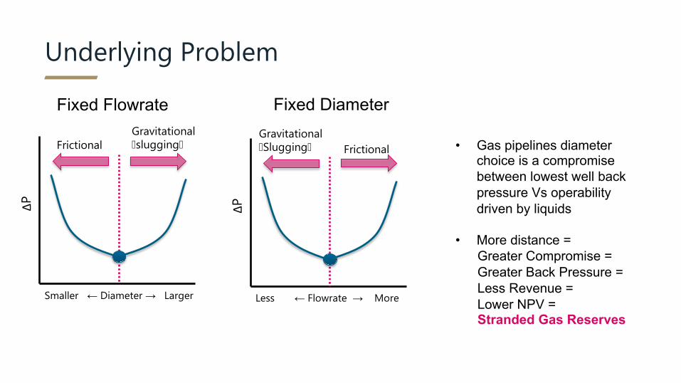
Underlying Problem
ΔP
Less ← Flowrate → More
ΔP
Smaller ← Diameter → Larger
• Gas pipelines diameter choice is a compromise between lowest well back pressure Vs operability driven by liquids
• More distance =Greater Compromise = Greater Back Pressure =Less Revenue = Lower NPV =Stranded Gas Reserves
Fixed FlowrateGravitational �Slugging�
Gravitational�slugging�Frictional Frictional
Fixed Diameter

Concept
• Compact - Installed as a pipeline in-line structure
• Passive - no moving parts or consumables
• Piggable
5
liquid
Wet gas
‘dry’gas

Configuration
SUTASS Manifold
XT
XT
Production Umbilical
Multiphase Flowline
Liquid Flowline
Gas Flowline
Power < 300 kWPower < 45 kW
Power < 45 kW
Processing Facilities
Booster Pump
Mini Pump
Mini Pump
NOTE: Reference Emerging Subsea Boosting Technology Insert
• Multiple PDG units are installed in-line and are piggable. Liquids are removed via small diameter pipe and small single phase centrifugal pumps �kW�
• Power, telecommunications cables, hydrate inhibitor such as MEG and other service lines are deployed by means of an umbilical.
6

Case Study
• Trunkline; 170km long• WD 0-1800m, no escarpment• Two manifolds and 9 satellite wells
DESIGN REQUIREMENTSDesign Flow Rate = 880 MMscfdTurndown Rate = 380 MMscfdArrival Pressure Early Life = 60 baraArrival Pressure Late Life = 30 baraLGR = 12 bbl/MMscf
170km
13 km
Infield flowlines between 2-5 km
Onshore
• 6 PDG units required• Efficiency linked to fluid conditions• Last PDG 80km from shore

PDGS Enabled Tie-back Hydraulics
0
20
40
60
80
100
120
140
160
60 bara, 880 MMScfd 60 bara, Turndown 30 bara, 880 MMScfd 30 bara, Turndown
Req
uire
d Pi
pelin
e In
put P
ress
ure
Standard FA (30") PDG System (36") Dry Gas (36")
• 55 to 80 bar reduction in wellhead back pressure across design cases
70-120+ bar in actual studies 1
Bcf/d

PDGS Enabled Tie-back Hydraulics
0.001
0.010
0.100
1.000
10.000
100.000
0 20 40 60 80 100 120 140 160 180
Trun
klin
eLi
quid
Hol
dup
(%)
Horizontal Distance (km)
Std FA - 880MMscfd - 30in TL PDGS - 880MMScfd - 36in TL
% on log scale
Effective Dehydration
No membranesNo consumablesNo pressure loss
Suppression of hydrocarbon phase

PDGS Gas Condensate Behaviour
• Analogues of subsea gas systems have shown that the condensates continue to drop out of the gas after it reaches ambient temperatures due to pressure loss
• The drop out slows down / stops once the ambient temperature increases due to pipeline moving into shallower waters
Figure – Typical phase envelope
Figure – Typical Liquid drop out behaviour

OLGA 2017 – HD module
• Dynamic Steady State
• Turndown
• Ramp-up
• Shutdown
• Restart
Operational Performance

Turndown
Lower Minimum Stable Flow
Wet Gas Pipeline Minimum Stable Flow –380 MMscfd
* after 8 months operation
Flow Rate �MMscfd�
Wet Gas Total Liquid Content�m3�
PDG Total Liquid Content�m3�
880 2053 264
250 10857 258
100 42579 5183*

Shutdown
Liquid drains back to the separators
Liquid pumped back to shore
Extreme shutdown ~5000m3 can be drained
But time dependent:
• Pump size
• Liquid drainage to separator
• Gas sweeping to speed up drainage

Ramp-Up & Restart
Low liquid arrival rates onshore – no slug catcher needed

Development Plan2017 - Initiation
Pseudo Dry Gas incepted as an ideaFirst funding gained for engineering
definition and CFD studies
2018 – Engineering DefinitionAll related hardware & power systems at TRL 5-7Liquid removal at TRL2 OGTC joint study on known stranded gas fields. A number of Operators and tier 1 contractors joined the project
2019 to 2020 – Prototype (Flow Loop) First Prototype tests completed
Liquid removal to TRL4 Work with OGTC to identify pilot test
Operator / contractor collaboration opportunities
2021 - 2022Install fully functioning pilot
TRL1
TRL2
TRL4
TRL6
2018 / 19
• Kicked off a techno-economic study for the Oil and Gas Technology Centre (OGTC) to assess the potential benefits of the PDG technology; within their portfolio of subsea initiatives (marginal, long distance, deep water)
• Testing of a prototype in lab conditions (CranfieldUniversity (UK))
• Open to work with other Operators/ Organisations• Proof of concept studies• Invitations to participate
in peer reviews15