Pryda’s Specifi cation Guide for Floor and Rafter Truss Systems · The timber for these trusses...
48
Pryda’s Specification Guide for Floor and Rafter Truss Systems April 2012
Transcript of Pryda’s Specifi cation Guide for Floor and Rafter Truss Systems · The timber for these trusses...
www.pryda.com.au
3
Pryda’s Specifi cation Guide for Floor and Rafter Truss Systems
April 2012

www.pryda.com.au
Pryda Floor Truss System
Introduction ...............................................................................6Pryda Longreach Trusses .........................................................6Pryda Span Trusses .................................................................6
Frequently Asked Questions and Answers ............................7
Product Benefi tsNet Installed Cost Benefi t .........................................................8Design Benefi ts ........................................................................9Construction Benefi ts .............................................................10
Design ConsiderationsGeneral Information ................................................................11Permanent Actions (Dead Loads) ...........................................11Imposed Actions (Live Loads) ................................................11Computing Wall and Roof Loads on Floor Trusses .................12Guidance on Other Loads ......................................................12
Factors Affecting Floor PerformanceTruss Orientation ....................................................................13Flooring Material ....................................................................13Strong-Backs .........................................................................13Bearing ..................................................................................13Supporting Beams .................................................................13No Ceiling Underneath Trusses ..............................................13
Serviceability ...........................................................................14
Fire and Sound Resistance ....................................................14
DurabilitySub-Floor Ventilation ..............................................................14Corrosion Protection ..............................................................14Protection of Exposed Cantilever Areas ..................................14
DetailEnd Types ..............................................................................15Internal Walls
Internal Non Load-Bearing Walls – Over Floor Truss ...........19Internal Non Load-Bearing Walls – Under Floor Truss .........20Internal Non Load-Bearing Bracing Walls – Under ..............20Load Bearing Walls – Under Floor Truss .............................20
External WallsFully Supported End Truss ..................................................21End Truss Under Gable Roof ..............................................21End Truss Carrying Roof Loads Over ..................................21Offset Load-Bearing Walls ..................................................21Support of Concentrated Loads .........................................21Floor Openings ...................................................................22Beam Pocket Detail ............................................................22Block Detail ........................................................................22Stairway Parallel to Trusses ................................................23Stairway Perpendicular to Trusses ......................................23
Floor Set Down ......................................................................24Ducts for Mechanical Services ...............................................24Cantilevers
Internal Cantilever ...............................................................25External Cantilever (Balconies) ............................................25Cantilevered Support Off-Set Walls .....................................26Outrigger Support of Off-Set Walls .....................................26
Strong-BacksSize Beam Selection ...........................................................27Splice Detail .......................................................................27Non-Aligned Strong-Backs .................................................28Strong-Backs Not Required ...............................................28
StabilityGeneral ..................................................................................28Wind Bracing .........................................................................28 Lateral Bracing of Floor Trusses Chords .................................28End Bracing ...........................................................................29Bracing Walls Supported by Cantilever ...................................29Fixing at Supports ..................................................................30Face Fixing of Floor Trusses ...................................................30
Installation ...............................................................................31
Pryda Rafter Truss System
IntroductionPurlin Trusses .........................................................................32Rafter Trusses ........................................................................32
Product Benefi ts .....................................................................32Design Considerations
Design LoadsPermanent Actions (Dead Loads) .......................................33Imposed Actions (Live Loads) .............................................33Wind Actions (Wind Loads) ................................................33
Ducts for Mechanical Services ...............................................33
Factors Affecting PerformanceDefl ection Limits .....................................................................34Special Loading Conditions ....................................................34
StabilityTop Chord Bracing .................................................................34Bottom Chord Bracing ...........................................................34Cantilever Bracing ..................................................................34Fixing to Supports ..................................................................34
DetailEnd Confi gurations ................................................................35
Appendices:
A - Producer Statement .........................................................36B - Typical Layout ...................................................................38C - Detailers Guide / Check List ...........................................39D - Design Request Form ......................................................40E - Floor Truss Span Tables
Normal Domestic Loads.........................................................41Commercial Offi ce Loads .......................................................42Important Notes about Span Tables .......................................42
F - Rafter or Purlin Truss Span Tables ..................................43Normal Domestic Loads.........................................................43Commercial Building Loads....................................................43
G - Impact of Higher Permanent Loads ...............................44
www.pryda.com.au
3

www.pryda.com.au
4
www.pryda.com.au
PRYDA FLOOR TRUSS SYSTEM
END DETAIL (Page 15)
DUCTS/SERVICES (Page 24)
CANTILEVERS (Page 25)
LONGREACH TRUSS (Page 6)
PRYDA SPAN TRUSS (Page 6)
INTERNAL SUPPORTS (Page 19)
CANTILEVERS (Page 25)

www.pryda.com.au
5
END DETAIL (Page 15)
END DETAIL (Page 15)
STRONG-BACKS (Page 27)
OPENING DETAILS (Page 22)
STABILITY BRACING (Page 28)
INTERNAL BRACING WALLS (Page 20, 29)

www.pryda.com.au
6
INTRODUCTION
Pryda Floor Truss Systems are a complete structural system for timber fl oors made up of fl ooring material, fl oor trusses, Strong-Backs, connections and bracing. They have been proven over many years and provide occupiers with fl oors that have an excellent and predictably reliable performance.
The timber for these trusses is on fl at, which provides a stable platform during installation and minimizes the overall depth required. All trusses use commonly available timber and most fl oor trusses in Australia are made from 70mm or 90mm dry timber.
There are two different types of web systems for these trusses. Both have timber chords but Pryda Longreach uses all-timber webs, while Pryda Span uses metal webs for the diagonals and timber webs for the verticals.
Both systems of Pryda fl oor trusses are generally made to order by licensed fabricators. While there are standard end details that allow trusses to be trimmed on site, this practice is not common. This is not only because all trusses are designed for an exact span for economic reasons, but the interaction between the true span of the trusses and the fl ooring should be considered for proper dynamic performance assessment.
Pryda Longreach Trusses
Longreach trusses are a premium performance product using nail-plated, all-timber components of any depth, but typically 300mm deep for residential fl oors and 400mm deep for commercial fl oors.
Pryda Longreach trusses are referenced as FT200, FT250, FT300, FT350 and FT400, where “FT’ means Floor Truss, and “200” is the nominal overall depth (mm). The actual depth dimensions are in nominal size steps, or may be individually specifi ed as required for the particular project.
Pryda Longreach can be designed for all common fl oor loads, including commercial loadings up to 5 kPa or point loads up to 6.7 kN. These trusses are slightly heavier than Pryda Span trusses and being all-timber generally have a stiffer performance as they can dissipate fl oor vibrations very well, and the nail-plates connecting the webs and chords are quite substantial.
Pryda Span Trusses
Pryda Span trusses have metal diagonal webs for light weight and economy. They are ideal for shallower trusses where there is more clearance room to accommodate the plumbing than with timber webs and for trusses where the chord design has some reserve capacity, as is often the case. In some Instances, a few diagonal metal webs may have to be replaced by timber webs in these trusses, as load or geometry considerations dictate.
Webs may be on both faces of the truss or just on alternate faces, and in the latter case this allows for the webs to overlap.
Pryda Span trusses are referenced as PS25, PS30, and PS40, where “PS” means Pryda Span, and “30” is the nominal overall depth (cm). The overall depths are nominally 250, 300 and 400mm deep. The actual depth dimensions are in nominal size steps according to the metal web used, and if required, the specifi c depth should be obtained from the Pryda licensed fabricator.
Pryda Span is manufactured using light gauge metal webs and are lighter than Longreach, but this is considered during the design process. The metal web system can be very cost-effective, especially if the truss chords have reserve capacity, as is often the case. The nail plates and Pryda Span metal webs are made to exacting standards from G2 grade steel with a minimum of Z275 galvanised coating.
PRYDA LONGREACH TRUSS
Timber Webs
PRYDA SPAN TRUSS
Metal Webs

www.pryda.com.auwww.pryda.com.au
7
FREQUENTLY ASKED QUESTIONS & ANSWERSQ. What is the market point of difference for this product?
A. Pryda fl oor and rafter trusses are customised for each job, including required stiffness, depth, timber grades and span. It will be computer designed for optimal performance, cost and installation effi ciency while minimizing waste.
The open web design ensures services are easily installed. There is no drilling or notching, saving time on site.
Extra long spans and large cantilevers can be provided, with the ability to support high loads. Spans up to 7.1m at 400mm depth can be achieved.
Signifi cant design improvement with minimal cost increases can be achieved with the Pryda Longreach (timber web) truss, by simply increasing its depth.
There is a large selection of end support types for quick and easy installation. Pryda fl oor and rafter trusses arrive on site manufactured to size and ready to install, eliminating the need to trim on site.
Set down or recess sections can be designed and prefabricated into the fl oor truss. This results in signifi cant labour savings when it comes to laying fl oor coverings on balconies or fi xtures and tiles in the bathroom.
Q. What is it made from and is it “green”?
A. Pryda produces two types of fl oor and rafter truss products, Pryda Longreach, which contains timber webs joined with steel nailplates and Pryda Span which is manufactured with metal webs.
Both products are manufactured using timber top and bottom chords. On average the timber component of the fl oor truss makes up 70% of the cost of the product.
Timber frame buildings are now being designed to meet low energy construction standards as timber has a high standard of thermal comfort while consuming minimal non-renewable energy. A principal objective for responsible design of environmentally friendly timber construction is to minimise life cycle energy consumption. Timber in lightweight construction is a superior material compared to manufactured material such as steel, concrete and masonry as it uses a comparatively small amount of non-renewable energy in its extraction and manufacture.
Timber maximises the effi ciency of insulation materials because wood never gets cold or dissipates heat, therefore less energy is required to maintain warmth in a building, and the less energy used, the less damage to the environment.
Today timber is available with a variety of popular and very cost effective treatments that can make it an extremely durable and termite resistant building material.
The metal webs used in Pryda Span are manufactured from Bluescope Steel G2 grade with Z275 galvanised coating.
The Pryda Claw® nailplates used for joining of timber in the construction of both Pryda Longreach and Pryda Span fl oor and rafter trusses are manufactured from Bluescope Steel G300 grade with Z275 galvanised coating.
It should be noted that steel is 100% recyclable and by volume is the most recycled material in the world.
Q. Is it expensive?
A. If you are comparing fl ooring systems’ cost on a per lineal metre basis, there are less expensive alternatives. However you need to consider the “net installed cost”. Pryda fl oor and rafter trusses can provide both installation and design savings.
As stated earlier, each job is customised to ensure the most cost and design effi cient outcome. In addition signifi cant design improvements can be made by simply increasing its depth at minimal cost increases.
Floor trusses can span further than alternative fl ooring systems, which may result in savings in additional support structures. E.g. Internal load bearing walls, steel beams.
Q. Is it easy and quick to install?
A. On site, the Pryda fl oor and rafter truss products are generally quicker to install than other types of joists or rafters. As the truss end support connections are all prefabricated there is no cutting or complicated fi tting required, which will speed-up installation and minimize mistakes. There are 20 end support type options available.
The open-web design of the product eliminates potentially damaging practices such as cutting out sections for services or drilling large holes. This ease of access for installing services including plumbing, heating ducts, electrical wiring and electronic data cabling is a major benefi t to builders.
Q. What accreditation does the product have?
A. Pryda Build software is used by licensed Pryda truss and frame fabricators to produce designs and manufacturing specifi cations for Pryda fl oor trusses.
Pryda Build has been independently assessed by professional consulting structural engineers for compliance with the Building Code of Australia, BCA 2010, and its referenced documents.
Pryda has also demonstrated compliance with the requirements set out in the ABCB Handbook “The Use of Structural Software for Building Design Approval” (2007).
All licensed Pryda fabricators are trained by Pryda in the use of Pryda Build. Users are issued with a Certifi cate of Training if they have demonstrated an acceptable understanding of the features presented during the course. Evidence of this training to any fabricator using Pryda Build may be obtained on request.
In addition the following reports are available and they can each be produced by a licensed Pryda fabricator:
• Producer Statement Report – a statement of design compliance for the whole job with overall and nominal design criteria, and BCA referenced documents.
• Plan Layout - showing the roof and all trusses laid out; all bracing (input by users); special notes for installation; all truss-to-truss connections.
• Detail Sheet – a drawing of each truss with all relevant design parameters associated with that particular truss.
• Design Report (summary) – all general loads; all applied distributed loads; truss serviceability displacements for major loads; support reactions; critical member timber designs details; bearing requirements; and nailplate design details at critical joints.
• Design Report (detailed) – as for the summary report, plus the results of the analysis for the 4 most critical combined load cases; all timber member designs; all nailplate joint designs.
Q. Where can I get it?
A. Pryda fl oor trusses are available through licensed Pryda truss and frame fabricators. You can locate your preferred fabricator via our website, www.pryda.com.au or by calling 1800 810 741.

PRODUCT BENEFITSPryda Floor Truss Systems offer many benefi ts to the designer, the builder and the building owner in providing a reliable high performance system for both domestic and light commercial construction. The use of the Pryda Floor Truss System results in a very cost effective, high quality product that is suffi ciently fl exible to accommodate the most complex of building requirements.
Net installed cost benefi t
The Pryda fully engineered open-web timber fl oor truss systems with timber webs (Pryda Longreach) or metal webs (Pryda Span) have many advantages that result in a lower net installed cost compared to other systems that are available. In some instances there may be a material cost increase by using Pryda fl oor trusses over alternative fl ooring systems. However when it comes to installing the product Pryda fl oor trusses can provide signifi cant labour savings. In addition, fl oor trusses have some considerable design advantages that could result in reducing the need for a large amount of costly structural support construction. E.g. Long spans may reduce the need for internal load bearing walls.
Go to the Pryda website www.pryda.com.au to view the St. Clair Park Village case study. There was a 6% increase in material costs by using Pryda Longreach fl oor trusses over solid joists. Framing time was reduced by 2 weeks and the labour saving was 2.5 times larger than the material cost increase.
Examples of these advantages are as follows and should be considered in the assessment of the overall cost of the fl ooring system:
Design cost savings
• Cost Effi cient Design. Each fl oor truss is customised for the job, including required stiffness, depth, timber grades and span. It will be computer designed for optimal performance and cost and installation effi ciency while minimizing waste.
• Signifi cant Design Improvement With Minimal Cost Increases. Span capacity and stiffness can be signifi cantly enhanced by simply increasing the depth of the Pryda Longreach fl oor truss. Due to the timber web design of the fl oor trusses, the increase in depth is at a minimal cost.
• Greater Design Flexibility. Extra long spans and large cantilevers can be provided, with the ability to support high loads. Spans up to 7.1 metres at 400mm depth using MGP12 pine can be achieved. This results in the following design and cost benefi ts:
- The long spans can potentially eliminate the need for some interior support walls and beams, giving more scope to architects and designers thus reducing the cost of the support structure.
- Large spans within restricted height applications can be achieved with Pryda fl oor trusses. In some cases the use of fl oor trusses may eliminate the need to use costly steel beams.
- Ideal for sloping blocks. In some instances fl oor trusses could be used to eliminate or reduce the excavation costs associated with sloping blocks.
Labour cost savings
• Set Down or Recess sections. The ability to design and manufacture set down sections into the fl oor trusses provides signifi cant labour savings in the following situations:
- In cantilever and balcony areas where the provision of adequate fl ashing and accommodation of different fl oor covering material thicknesses is critical.
Example of set down section for a balcony
- Bathrooms, toilets and other wet areas may also require the fl oor surface to be set down. This will provide signifi cant labour savings when other trades start installing bathroom fi xtures, fi ttings and tiling.
Example of an internal set down area
www.pryda.com.au
Set Down Section
Set Down Section
8
Long cantilevers make fl oor trusses ideal for sloping blocks

• No Cutting, Drilling or Notching. The open webs and voids designed to allow easy fi xing of electrical, plumbing, ducts and energy services. There is no need for drilling or notching, saving time on site.
Example of voids and open webs accommodating services
• Quick Installation. A large selection of end support types for quick and easy installation. Pryda fl oor trusses arrive on site manufactured to size and ready to install, eliminating the need to trim on site. There is no material or labour wastage. Pryda fl oor trusses are designed and manufactured with end types for fast, secure fi xing to steel, concrete, masonry or timber. Go to page 15 or the Pryda website www.pryda.com.au to view the available options.
Example of end type designed for fi xing to masonry
Example of end type designed for fi xing to steel beams
www.pryda.com.au
Void Used For Service Duct
Service PipesBetween Webs
Walling Plate
Overhang Any Length
Min. Bearing 30mm on Primary Bearing Point
9
In addition to providing net installed cost savings there are numerous design and construction benefi ts of Pryda fl oor truss systems, they are as follows:
Design Benefi ts
• Assured Performance. Pryda fl oor and rafter truss systems have been used with outstanding results for over 15 years by designers and builders.
• Design Versatility. The long span capacity - up to 8 metres or more - offers functional design freedom and can eliminate the need for interior support walls and beams.
• Depths to Suit. Wide range of standard depths available – from 200 to 450mm - or can be manufactured specifi cally for a particular project.
• Limited Space. Designs can accommodate large spans in restricted height applications.
• Cost Effective. Timber grade in chords is selected to suit the design requirements of each individual project to provide the most cost effective system.
• Larger Spans at Low Cost. With all-timber trusses (Pryda Longreach) the span capacity increases signifi cantly as the truss depth increases - at little extra cost.
• Commercial Applications. Pryda fl oor trusses not only accommodate domestic loads but may also be designed for light commercial applications including offi ces, schools, hospitals and function areas.
• Designed to Order. Stiffness required, depth, timber grades and sizes can be varied to suit any individual job requirements. Computer designed for optimal performance effi ciency and lowest material cost.
• Wide Range of End Supports. Standard end support types suit structural connections to steel, concrete, masonry or timber.
• Extra Stiffness in Floors. Stiffer than other fl oor systems with established dynamic limits to ensure rigidity and to overcome springiness and bounce. Designed to provide a fl oor that feels and acts “rock-solid”.
• Accommodates Large Ducts. Large rectangular ducts to 500mm wide can fi t within the standard design and special duct routing within rows of trusses can be incorporated.
• Dimensionally Stable. Fully kiln-dried timber ensures stability, free from movement due to shrinkage.
• Effi cient Use of Timber. More effi cient use of natural resources than solid timber joists.
• CAD Compatible. Standard data and design details available on CAD.
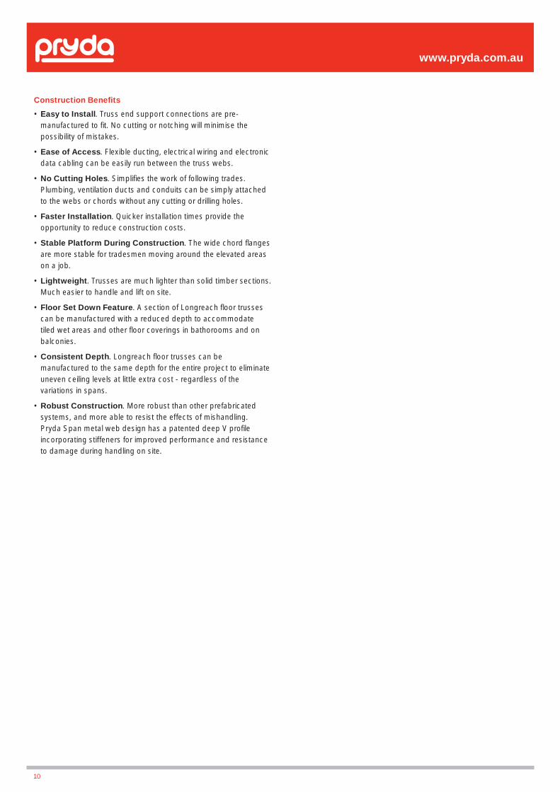
Construction Benefi ts
• Easy to Install. Truss end support connections are pre-manufactured to fi t. No cutting or notching will minimise the possibility of mistakes.
• Ease of Access. Flexible ducting, electrical wiring and electronic data cabling can be easily run between the truss webs.
• No Cutting Holes. Simplifi es the work of following trades. Plumbing, ventilation ducts and conduits can be simply attached to the webs or chords without any cutting or drilling holes.
• Faster Installation. Quicker installation times provide the opportunity to reduce construction costs.
• Stable Platform During Construction. The wide chord fl anges are more stable for tradesmen moving around the elevated areas on a job.
• Lightweight. Trusses are much lighter than solid timber sections. Much easier to handle and lift on site.
• Floor Set Down Feature. A section of Longreach fl oor trusses can be manufactured with a reduced depth to accommodate tiled wet areas and other fl oor coverings in bathorooms and on balconies.
• Consistent Depth. Longreach fl oor trusses can be manufactured to the same depth for the entire project to eliminate uneven ceiling levels at little extra cost - regardless of the variations in spans.
• Robust Construction. More robust than other prefabricated systems, and more able to resist the effects of mishandling. Pryda Span metal web design has a patented deep V profi le incorporating stiffeners for improved performance and resistance to damage during handling on site.
www.pryda.com.au
10
www.pryda.com.au
DESIGN CONSIDERATIONSGeneral Information
Floor trusses are to be designed for a combination of permanent actions (dead loads) and imposed actions (live loads) in accordance with the loading standards referenced in the Building Code of Australia (BCA)
Permanent Actions (Dead Loads)
Permanent actions are defi ned in AS/NZS 1170.1:2002 to include, but not limited to, actions of the following items:(i) Weight of fl oor systems: This includes fl ooring material, fl oor
coverings, self weight of supporting members etc. Eg: Tiled fl oors apply larger loads than carpeted fl oors
(ii) Weight of walls: eg: external load bearing walls or heavy inter-nal tiled or acoustic walls need special attention.
(iii) Weight of roof: any loads transferred down from the roof to the fl oor should be considered.
(iv) Fixtures and fi ttings: spa baths, kitchen benchtops etc are capable of infl uencing design.
(v) Storage: loads from book shelves, billiard tables etc which are likely to be in place for long periods should be treated as permanent in nature.
Mass of Floor(kg/m2)
Description of Floor Constructions
25Standard fl oor up to 22mm particleboard with
carpet or vinyl fl oor covering and no ceiling
40
Standard fl oor up to 22mm particleboard with carpet or vinyl fl oor covering with 10mm
particleboard ceiling (Typical mass given in AS 1684)
5018mm fi brecement sheet (wet areas) with
lightweight fl oor covering with 10mm plasterboard ceiling
7575mm Hebel fl oor with carpet or vinyl fl oor covering with 10mm plasterboard ceiling
8518mm fi brecement sheet (wet areas) + ceramic
tiles on adhesive with 10mm plasterboard ceiling
11018mm fi brecement sheet (wet areas) + ceramic
tiles on 40mm mortar bed with 10mm plasterboard ceiling
Table 1 – Typical Floor Construction Weights
Table 2 – Typical Wall Construction Weights
Table 3 – Typical Roof Construction Weights
Mass of Wall(kg/m2)
Description of Wall Construction
15As used in AS 1684 – typical for external walls
with cladding on one side only
25Typical lightweight internal walls with 10mm
plasterboard on each side or a combination of plasterboard and 6mm fi bre-cement sheet
45Heavyweight internal sound proof walls with
2 layers of 13mm Soundcheck plasterboard on each face
60Heavy-weight internal sound proof walls with
2 layers of 16mm Fyrchek plasterboard on each face
70Heavyweight external walls with Hebel Power
Panel on external face and 10mm plasterboard on internal
Mass of Roof(kg/m2)
Description of Roof Construction
10 Steel sheet roofi ng 0.48mm thick with battens
20Metal sheet tiles or 0.55mm thick steel sheet roofi ng. 12mm softwood ceiling lining, sarking
and lightweight insulation
30Steel sheet roofi ng 0.75mm thick.
13mm plasterboard ceiling, roof and ceiling battens, sarking and lightweight insulation
40Steel sheet roofi ng 0.75mm thick, high density fi bre-cement ceiling, roof and ceiling battens,
sarking and lightweight insulation
60Terracotta or concrete tiles and roof battens
with no ceiling
75Terracotta or concrete tiles, roofi ng and ceiling
battens, 10mm plasterboard ceiling, sarking and insulation
90Terracotta or concrete tiles, roofi ng and ceiling battens, 19mm hardwood ceiling, sarking and
insulation
Imposed Actions (Live Loads)
Imposed actions are the transient loads that are placed on the fl oor due to people, furniture etc. These loads are an estimation of the temporary occupation and the associated use of the space that the fl oor supports. Typically trusses are designed for a uniformly distributed live load and a ‘moving’ concentrated load. These two loads are considered separately – whichever produces the most adverse effect.
Table 4 - Typical Imposed Actions on Houses
Load Type General areas Balcony
Uniformly distributed load 1.5 kPa 2.0 kPa
Concentrated point load 1.8kN 1.8kN
11

www.pryda.com.au
12
Note to Engineers: If the fl oor trusses are intended to carry loads other than houses, then the relevant information should be passed on to the truss manufacturer prior to the design process. Read AS/NZS 1170.2: 2002 for complete details of imposed actions. Below is an extract from this code:
Table 5 – Typical Imposed Actions on Commercial Buildings
Loads from External Load-Bearing Walls
External load-bearing walls supported by fl oor trusses are becoming increasingly common in today’s designs. The ability for fl oor trusses to carry load-bearing walls has enabled designers to delete steel beams from the fl oor frame and help achieve economical designs.
In addition to the FLW, wall weight and wall height, the roof load width (RLW) and the roof mass are also required to determine the point load on the fl oor truss.
The RLW is computed similar to AS1684, using half truss span + overhang, and dividing the sum by the cosine of the roof pitch.
Floor Application Uniformally Distributed Load
kPa
Point LoadkN
Assembly areas 3.0 - 5.0 2.7 - 3.6
Public corridors and spaces 4.0 - 5.0 4.5
Stages 7.5 4.5
Offi ces 3.0 4.5
General storage 2.4/m height 7.0
Drill rooms and halls 5.0 9.0
Computing Wall and Roof Loads on Floor Trusses
This section provides guidance on how to determine additional loads applied on fl oor trusses from internal and load-bearing external walls.
Defi nitions:Mr = Mass of Roof (kg/m2) – Refer Table 3Mw = Mass of Wall (kg/m2) – Refer Table 2RLW = Roof Load Width (m)FLW = Floor Load Width (m)Hw = Wall Height (m)
Note: The fl oor load width (FLW) is usually taken as the spacing of fl oor trusses. However, if the spacing is irregular, then FLW is the sum of half-spacings from the truss in consideration to the respective adjacent trusses.
Loads from Internal Non Load-Bearing WallsA knowledge of the fl oor load width (FLW), the mass of wall (refer Table 2) and the wall height is required to determine the point load applied on the fl oor truss.
Dead Load (P) in kN:
P = Mw * Hw * FLW /100
P
Floor Load Width(FLW)
Internal non load-bearing wall load on fl oor truss
(FLW)
P
P
External loadbearing wall loads on fl oor truss
Dead Load (P) in kN:
P = (Mr * RLW + Mw * Hw ) * FLW/100Roof Load Wall Load
Any concentrated wall studs (supporting girder truss) or jamb studs should be treated separately, and specially designed fl oor trusses may be provided at these specifi c locations.
Guidance on Other Loads
Spa Baths
Modern spas are generally made out of acrylic or metal and come in different shapes having light-weight shells. However, spas that are made out of cast iron, stone etc and those needing grout bedding are signifi cantly heavier and therefore require special attention.
Licensed Pryda fabricators have the facility to apply a load area on the fl oor layout to simulate loadings from spa baths using Pryda’s proprietary software, Pryda Build i. For eg: Acrylic or metal spa baths (without grout bedding) would typically apply a permanent load of 40 kg/sqm and an imposed load of 2.0 kPa over the load area. Note: The base area of the spa would determine the load area.
Other Heavy Loads
Where special load cases are to be applied to the fl oor trusses such as heavy ceramic tiles etc, adopt design charts provided in the Appendix.
For other heavy furniture items like billiard tables, grand pianos etc, seek advice from a Pryda Design Offi ce.

FACTORS AFFECTING FLOOR PERFORMANCEFloor liveliness, or bounce, has been an intermittent issue over the years with lightweight residential fl oors - for all forms of timber and steel construction. To eliminate these problems, Pryda Floor Systems are designed to stringent dynamic performance criteria.
The fl oor truss is only one component that can affect the fl oor performance. On-site conditions are always important and proper attention to detail must be taken at the time of installation.
Truss Orientation
To ensure the fl oor performance it is important that all trusses are installed as designed. That is in the correct location, orientation and the right way up. The fl oor truss layout provided by the authorized Pryda fabricator should be used to position all trusses and the diagrams below used to ensure the trusses are installed the correct way up.
Flooring Material
The fl ooring material has a signifi cant effect on the perceived bounciness of a fl oor. It has the ability to spread human impact loads depending on the material and the thickness. Plywood acts differently to particleboard, and T&G acts differently to both. A simple way to improve fl oor performance is to select fl ooring that is stiffer (e.g. thicker) than the minimum for your chosen application.
Strong-Backs
These are timber members, e.g. 140 x 35mm running at right angles to the trusses. There is generally one row down the centre, but there could be more with larger spans. Their main function is to help the fl ooring spread footfall impacts to adjacent trusses. They become of greater importance as the spans and loads become larger. It is important that Strong-Backs be properly attached to the truss vertical webs as detailed, as poor fi xing techniques, such as having large gaps between the Strong-Back and the web, can reduce the Strong-Back effectiveness considerably.
Bearing
Trusses must bear directly on their supports and not be held above them by the fl ooring. This may sound odd, but where the support top plate is not level, and the fl ooring is nailed to the truss top chord, the fl ooring itself can lift the lower truss(es) by a few millimetres and this considerably worsens the perception of fl oor bounce. This situation is diffi cult to observe during the early stages of construction and in any Instance of potential fl oor performance complaint it should be checked using a piece of card to see if there are any gaps between the trusses and their supports.
It is important that fl oor trusses bear over the support wall plate or beam with a minimum of 30mm for residential fl oors and 40mm for commercial fl oors. This requirement is implemented to ensure that localised crushing of the top plate or bottom chord does not occur. It also encourages suitable load transference between upper load-bearing wall frames and lower wall frames.
Supporting Beams
If any fl oor system is supported on beams — e.g. steel or timber lintels/beams— the amount of fl oor bounce in that area can become unacceptable if it is not properly assessed at design time. The dynamics of any supporting beam and the dynamics of the truss must be considered simultaneously as they interact with each other. Each can be satisfactory in its own right, but not satisfactory in combination.
No Ceiling Underneath Trusses
If there is no ceiling fi xed directly underneath the trusses, install 90 x 35 F5 (on fl at) lateral ties to the bottom chord, located approximately at the third points of the span. This will prevent one type of undesirable dynamic response which is otherwise normally prevented by the ceiling (if fi xed directly to the truss bottom chords) or ceiling battens.
www.pryda.com.au
Right Way Up
Right Way Up
Wrong Way Up
Wrong Way Up
13

SERVICEABILITYServiceability is an important consideration in fl oor truss design, and is often acceptance of a fl oor system is dictated by its performance under serviceability conditions.
Pryda fl oor trusses are designed for both defl ection and dynamic criteria. The defl ection limits are based on the recommendations given in AS1684.1 and those suggested in Table C1 of AS/NZS 1170.0:2002.
As part of the Dynamic performance, to ensure fl oor trusses are acceptable with regard to ‘springiness’ or ’bounce’, additional criteria are adopted, apart from the ones suggested in the above codes. The natural frequency of the fl oor system (assuming rigid supports) is determined, and the users of Pryda’s proprietary software have the option of nominating three levels of dynamic performance based on the frequencies – Enhanced (minimum 10 Hz), Normal (8 Hz) and Minimum (7 Hz)
Note: The dynamics of a fl ooring system are characterised by the perceived frequency of vibration in the fl oor under a specifi c load. The rigidity of the supporting structure can have a signifi cant effect on the dynamic performance of the fl oor system. For example, fl oor trusses supported by rigid walls will seem to exhibit less bounce than the same trusses supported by fl exible beams that allow some level of support movement.
It is the responsibility of the building designer or engineer carrying out the design of fl oor beams to consider the effect of them on dynamic performance.
FIRE AND SOUND RESISTANCEPryda fl oor trusses may be used in fi re or sound rated construction, in combination with cladding material that is rated to fulfi l its function.
Fire resistance levels are normally referred to as FRL and are expressed in minutes as 60/60/60 (or similar) to refl ect the structural adequacy, integrity and insulation respectively.
Sound resistance levels are given in two forms – airborne sound and impact sound. The former is expressed as Rw (weighted sound reduction index) and a value of RW 50 is typically applied to fl oors and walls – the higher the number, the better the performance is. The latter is expressed as Ln,w (weighted normalised impact sound pressure level). A value of 62 Ln,w is common – the lower the number, the better the performance is.
These fi re and sound resistance levels for classes 2, 3 and 9c buildings are given in the Building Code of Australia (BCA). Some manufacturers of cladding material, eg: CSR Gyprock, Boral Plasterboard, Lafarge Plasterboard etc, have provided technical manuals that illustrate construction technique and assemblies that comply with the BCA “Deem to Comply’ provisions.
Generic details of construction and typical assemblies incorporating fl oor trusses may be found in Technical Manual by Forest & Wood Products Australia (FWPA)-“Timber-framed construction for multi-residential buildings classes 2, 3 and 9c.
DURABILITYSub-Floor Ventilation
Adherence to the recommendations of the BCA relating to sub-fl oor ventilation is critical to ensure the long-term serviceability of fl oor trusses that form part of the sub-fl oor. Clause 3.4.1.2 of the BCA requires that the sub-fl oor space must be: (a) cleared of all building debris & vegetation; and (b) be cross-ventilated by means of openings; and (c) contain no dead air spaces; and (d) ventilation openings are evenly distributed; and (e) be adequately graded to ensure proper surface water drainage.
Corrosion Protection
Pryda metal webs (Pryda Span fl oor trusses), and nailplates (Longreach fl oor trusses) are manufactured using Z275 light-gauge steel, having zinc coating of 275 gsm (total weight). This protection is adequate only for INTERNAL applications in most corrosion environments, except areas that are classifi ed as heavy industrial or those subject to high humidity (eg: enclosed swimming pools) etc. Under these circumstances, seek advice from experts as special protection will be required. Note: INTERNAL areas are those within the building envelope that are kept permanently dry.
In areas outside the building envelope that are exposed to repeated wetting (EXTERNAL areas), Pryda’s stainless steel products or equivalent should be considered. Some sheltered areas like open sub-fl oors with no perimeter walls may sustain worse corrosion than fully exposed conditions, and therefore is prudent to treat this as an EXTERNAL situation. Accordingly nailplates or metal webs used in fl oor trusses within a ‘open’ sub-fl oor should have additional corrosion protection.
Some alternatives to stainless steel include hot dip galvanised or powder coated steel, which are not supplied by Pryda. For more detailed information, read Pryda’s Technical Update on Corrosion Resistance of Pryda Products or contact a Pryda offi ce.
Protection of Exposed Cantilever Areas
Cantilevered areas that are exposed to the elements need special attention. An effective and durable barrier must be provided at the outside of external walls to completely prevent moisture penetration into the building.
All timber exposed to the weather, including timber covered with decking etc must be treated to H3 level or higher. Refer section on Cantilevers (page 25) for further details on this subject.
www.pryda.com.au
14

DETAILEnd TypesPryda fl oor trusses have the advantage of adapting to a range of different on-site support conditions. The dimensions of the 12 standard end types can vary to meet most detailing requirements. The joint details shown in this manual are intended as a guide only. Variations to these may be required and should be verifi ed.
The Pryda software includes many End Type detail drawings. Pryda highly recommends that designers select the relevant drawing(s) and add them to the fl oor truss layout. This is to ensure that the trusses are correctly installed on site.
Note on stability: The connection details shown in this section should be verifi ed by the project engineer to ensure lateral stability requirements of the building (and supporting beam) are met.
End Type 1
The most common end type is for bottom chord bearing on wall plate or steel section while also permitting upper wall frame to bear directly above. It may also be used for the connection to framing brackets. Note: It is preferrable to use 45mm end webs when fi xing into framing brackets.
End Type 2
Similar purpose as End Type 1, however permits timber end bracing trimmers to provide lateral stability. It also accommodates minor site variations by allowing the setbacks to be curtailed if need be.
End Type 3
Accommodates ease of installation of timber end bracing trimmers while also supporting upper loadbearing wall frame. It acts as an additional bottom plate and supports the edge of the sheet fl ooring.
End type 3 is the preferred option out of all of the bottom chord bearing types, especially when supporting heavily loaded walls. Also refer End Type 6 (with double end-webs)
www.pryda.com.au
END DETAIL TYPE 2.1
Max. Setback 45mm
Optional EndTrimmer
END DETAIL TYPE 2.2
Chords May beTrimmed to Suit
Max. Overhang 45mm
Load Bearing Wall
Continuous EndTrimmer
Block SupportingTrimmer
END DETAIL TYPE 3
15
Min. Bearing 30mm
Wall Plate
END DETAIL TYPE 1

End Type 4
Suitable for bottom chord bearing on the bottom fl ange of a steel channel or universal beam while also maintaining continuation of the fl ooring over the top of the steel beam.
End Type 5
Flexible end type that comprises of a solid block incorporated within the truss, either nailed and glued or nailplated as shown. This block may be cutback at an angle either on site or in the factory to accommodate off-set walls from upper level or facilitate support into steel beams.
Alternatively, End Type 5 with a full width end block is suitable for cantilevering over lower storey walls and carrying upper storey load bearing walls.
www.pryda.com.au
16
Top Chord Extension of AnyLength to Maintain Floor Level
Primary Bearing PointMin. 30mm
END DETAIL TYPE 4
END DETAIL TYPE 5.1Min. 100mm
Min. 300mm
END DETAIL TYPE 5.2
Max. 200mm
Max. 300mm
END DETAIL TYPE 5.3
Max. 150mm
As an additional application, the blocking piece may be cut to suit to form pelmets (fl oor trusses as shown) or box gutters (rafter trusses)
END DETAIL TYPE 5.4
Trimmable Ends: The nailed and glued solid block option may be adopted to achieve trimmable ends - especially useful when end supports are not parallel or when the true locations of the support are subject to minor variations. Contact a Pryda Design Offi ce for further advice including information on timber/fi xings and the limitations of these applications.
In some instances, an I-joist may be used in place of solid blocks. Contact a Pryda Design Offi ce for further advice.

End Type 6
Standard bottom chord bearing with the capacity to transfer high loads from upper loadbearing walls.
End Type 6 also provides extra timber nailing area when supporting trusses using Pryda Framing Brackets.
End Type 7
Top chord support on timber fl oor beam, steel beam or waling plate. Promotes easy installation. It is advised that bottom chord should be restrained (skew nails minimum) to obtain best results.
www.pryda.com.au
END DETAIL TYPE 6.1
Highly Loaded Wall
END DETAIL TYPE 6.2
Timber Beam
Pryda FramingBracket Supporting
Truss
END DETAIL TYPE 6.3Steel Beam
Timber ledger plate fixed to steel beam through packers to receive Pryda Framing Bracket (see below for fixing details)
END DETAIL TYPE 7.1
Min. Bearing 30mm
Skew Nails Preferable IntoBeam to Restrain Bottom Chord
END DETAIL TYPE 7.2
End Web Should be Max. 5mmFrom Edge of Supporting Member
END DETAIL TYPE 7.3
Waling Plate
17
Note: Timber ledger plate (min. 190x35) should be fully bearing on bottom fl ange of steel beam, and usually fi xed to web of beam through packers at 900mm c/c using 2/M10 bolts. Contact a Project Engineer for verifi cation of fi xing for commercial application.
End Type 8
Similar purpose to End Type 7 but permits support member (waling plate) to be concealed at variable depths within the truss,
End Type 9
Permits fl oor trusses to be supported on the top chord while also housing the supporting beam within the depth of the truss. Encourages continuous ceiling lines under trusses.
End Type 11
Permits support into steel channels and universal beams while maintaining a fl oor and ceiling level that fi nishes fl ush with the top and bottom fl ange.
End Type 12
Permits bottom chord support into steel channels and universal beams with the bottom chord fi nIshing fl ush with the bottom fl ange while also maintaining a fl oor level above the top fl ange.
Combination End Type
A combination of end types may be used to suit site conditions, for internal beams supporting fl oor trusses from both faces. In the illustration below, fl oor trusses having End Types 6 and 8 are supported on a steel channel (PFC).
www.pryda.com.au
18
Waling Plate
Min. Bearing 30mm on Waling Plate
Min. Top Chord Bearing 30mm
Max. 110mm
Max. 35mm
Min. Bearing 30mm on Primary Bearing Point
Overhang Any Length
Min. Bearing 30mm on Primary Bearing Point
End Type 10
This end type is suitable for short internal cantilevers alongside stair openings.

Internal WallsThese details refer to all internal walls which are non load-bearing for gravity loads, but which may also be wind bracing walls. If the fl oor is to carry load-bearing internal walls, adopt guidelines given in page 12.
Internal Non Load-Bearing Walls - Over Floor Truss
The fl oor truss system requires no additional stiffening when supporting non load-bearing walls; however special consideration is required for non load-bearing walls acting as wind bracing walls and those carrying wall tiles and other heavy cladding materials. Specifi ers should notify the Pryda licensed fabricator of wall bracing positions and capacities.
• Bracing Walls Parallel to the Floor Trusses
It is preferable to locate a fl oor truss directly under a non load-bearing bracing wall, and the supporting truss to be designed for reactions generated by these bracing walls. In order for this to happen, the truss designer requires suffi cient information on wall bracing of the supporting upper level at the time of the design, in particular the exact locations of bracing walls and the resulting reactions at their anchor points.
However, if the fl oor trusses were designed without any consideration for bracing walls that are supported on the fl oor above, then the installer is required to take remedial measures on site. For bracing walls having capacities up to 3.0 kN/m, the trusses are required to be upgraded as illustrated below for a likely situation where the bracing wall is positioned between two fl oor trusses.
www.pryda.com.au
Internal Bracing Wall(Non Load-Bearing)
2/No. 12 x 65Type 17 screws to Strongback
120 x 45mm F5 orMGP Upright
Member
3/3.75 x 90mm NailsFixing Upright to Topand Bottom Chords
120 x 45mm F5 or MGP Nogging
3/3.75mm x 90mm Nails FixingNogging to Upright Member
Fix Bracing Wall toNogging Using2/No. 14 x 90
Type 17 screwsat Each Floor
Truss Crossing UnderBracing Element
Fix Bracing Wall to Nogging Using2/No. 14 x 90 Type 17 screws
End ofBracingElement
Max. 2700m
m H
igh Wall
PERPENDICULAR BRACING WALL
PARALLEL BRACING WALL
3/3.75mm x 90 NailsFixing Nogging to Top andBottom Chords
12g x 65mm Timberfixx SelfDrilling Screws @ 450mmCentres
Max. Wind BraceCapacity of 3.0 kN/m
Max
. 270
mm
Hig
h W
all
Internal Bracing Wall(Non-Load Bearing)
Length ofBracing Element
120 x 45mm F5 or MGPUpright Member
Floor Trusses
3/3.75mm x 90mm Nails FixingNogging to Upright Member
Fix Bracing Wall to Nogging Using 2/No. 14 x 90 Type 17 screws
120 x 45mm F5 or MGP10 Nogging
2/No. 14 x 65 Type 17 screws
19
• Bracing Walls Perpendicular to Floor Trusses
Again, it is preferable to incorporate the loading from bracing walls at the time of the fl oor design. Alternatively upgrade fl oor trusses as shown in the illustration below to resist bracing walls of capacities not greater than 3.0 kN/m.
Note on fl oor trusses supporting bracing walls having capacities greater than 3.0 kN/m:
It is prudent to consider these bracing walls at the time of the design as it becomes almost impractical to adequately upgrade truss to suit on site. Contact a Pryda Design Offi ce for further advice.

• Fitted Flooring
Where a fi tted fl oor is being used, locate a double truss under each wall to provide support to both the wall and fl ooring. Alternatively, use supplementary ledger plates fi xed to the side of the fl oor trusses.
Internal Non Load-Bearing Walls - Under Floor Truss
Floor trusses must be adequately supported on the loadbearing supports nominated in the design. There may be a detrimental effect on the walls and the fl ooring system if the trusses bear on a non load-bearing wall. The tops of internal non load-bearing walls need lateral stabilizing by fi xing to the truss bottom chords. The trusses must be allowed to defl ect downwards, so Pryda Partition Hitches (product code: PHH) have been developed for this purpose, which should be nailed to the truss near the top of the slots.
Internal Non Load-Bearing Bracing Walls – Under Floor Truss
It is important that racking forces generated from stability and wind loads are transferred down through the structure to the foundations. The details below show how these forces can be transferred from the upper fl oor system, through truss bottom chords to lower storey non-load bearing bracing walls. Pryda Shear Connectors (Product Code: PSC) can be used for this purpose.
Load-Bearing Walls - Under Floor Truss
Important: Should an internal wall be required to support fl oor trusses, this intention should be made very clear on both the trusses and the truss layout. The supporting structure, footings, etc. should then be designed to cope with the high wall loads that can result.
Internal lower storey walls can be used for support to create single length trusses across the width of the building. Preferably, a double web with a gap will cater for small deviations in support positions, while a block insert of up to 600mm in length will accommodate larger deviations. Alternatively, if the exact location of the support is known, then a vertical web can be detailed at the support point.
• Internal Support Types
www.pryda.com.au
20
Fitted Flooring
FITTED FLOOR FIXING - 1
Non Load-Bearing Walls
FITTED FLOOR FIXING - 2
Non Load-Bearing Wall
Fitted Flooring
SINGLE WEB SUPPORT
Single Web
Internal Support Wall
• Walls Parallel
• Walls Perpendicular
A pair of Pryda Shear Connectors in combination with 90x35 F5 (min) fixed with 2/No.14 x 75 Type screws at each truss bottom chord
A pair of Pryda Shear Connectors in combination with 90x35 F5 (min) block (300mm long) fixed to bottom chord with 5 nails
External WallsThese details are for fl oors that support external walls both load-bearing and non load-bearing.
Fully Supported End Truss
Where the end fl oor truss is supported along its full length by a lower storey wall or by continuous base brickwork or footing while carrying an upper storey wall above, a simplifi ed fl oor truss, as shown, may be used.
End Truss Under Gable Roof
Where the end fl oor truss is located under a gable end roof and is free spanning, it is appropriate to use a single fl oor truss as it is carrying a non load-bearing wall and fl oor only.
End Truss Carrying Roof Loads Over
Free spanning end fl oor trusses are required to be designed for both roof and wall loads.
Use guidelines given in page 12 (Loads from External Load-Bearing Walls) to compute loads that are required to be applied on the end-fl oor truss.
Off-Set Load-Bearing Walls
Use guidelines given in page 12 to compute loads from off-set load bearing walls.
Support of Concentrated Loads
Please refer to a Pryda licensed fabricator for an individual design if a fl oor is to carry a concentrated point load other than as specifi ed below.
• For support of concentrated point loads refer above to the details for “Continuously supported end truss”.
• As specifi ed in detail below
www.pryda.com.au
FULLY SUPPORTED END TRUSS Lintel in
Accordancewith AS1684
ModifiedFloor Trusses
Additional Block Required
For Load-Bearing Stud Above
Braces at Max. 6000mm Centres
Jamb Studs with Lintel Over
BLOCKING UNDER WALL OR CONCENTRATED LOADS
Load-bearing wall at right angles to trusses or stud supporting concentrated load
Solid, FullDepth
Blocking,Minimum
35mm thick
Lower StoreyWall or Bearerand Footings
21
DOUBLED WEB SUPPORT
Double Web
Internal Support Wall
NAILED BLOCK SUPPORT
Max. 600mm
InternalSupport Wall
45mm Thick Block(Solild or Claw Joined)
FT250or Deeper

www.pryda.com.au
22
Floor Openings
Pryda fl oor trusses can be detailed to suit an opening in a fl oor, e.g. as required to accommodate stairways. A header beam is normally required to support the incoming trusses while a double lamination standard truss is often suitable to carry each end of the header beam.
Beam Pocket Detail
The trusses need to be detailed with a beam pocket wide enough to fi t the header beam as shown. The header beam should be blocked hard up against the underside of the carrying fl oor trusses and nailed to each vertical web with 4/3.15 x 75mm nails.
Block Detail
Alternatively, a solid block (600mm long) fi xed to the side of the trusses may support the header beam. The header beam may be notched into the solid block or fi xed to the block using a Pryda Framing Bracket as shown.
FLOOR OPENINGS
Curtailed Truss Span
Opening
Header Beam
Double Truss
BEAM POCKET
Header Beam
Solid Packing Under
PRYDA FRAMING BRACKET SUPPORTBlock Detail - 1
35mm Solid Block Fixed to Sideof Truss with 75mm x 3.75mmDia. Nails at 50mm Centres
Pryda Framing Bracket
Block Detail - 2
35mm Solid Block Fixed toSide of Truss with 75mm x3.75mm Dia. Nails at 50mm Centres
Use Double Truss FixingBlock at this Web
Header Beam
Pryda Triplegrip
600mm
Block Detail - 3
Alternatively, a solid block may be incorporated within the fl oor truss (as shown below) to receive supported beam.

www.pryda.com.au
Table 7
HEADER BEAM SELECTION TABLE
Maximum Supported Floor Truss Span (mm)
Header beam(max. 3500mm span)
1000 190x45 F17 or 200x45 LVL2000 240x45 F17 or 240x45 LVL3000 2/240x35 F17 or 200x63 LVL
4000 2/240x45 F17 or 2/240x45 LVL
Note: the above header beam sizes are given as a guide only. These beams may be substituted by other sizes and grades, having similar stiffness.
Stairway Perpendicular to Trusses-Case 2
Use Table 7 to determine header beam specifi cations for Case 2 only. The 900mm wide stairway runs perpendicular to the curtailed fl oor trusses and the header beam (max. 3500mm span) supports the trusses.
Stairway Parallel to Trusses-Case 1
Use Table 6 to determine header beam specifi cations for Case 1 only. The header beam (max. 2000mm span) supports the curtailed fl oor trusses and stair loadings from the upper fl ight of stairs.
LOAD CASE 1 - STAIR VOID SUPPORT
Double Supporting Truss
Header BeamSupported byDouble Floor Truss
Max. 7500mm
Max. 3000mm
2000mm
Header Beam Carrying CurtailedFloor Trusses and Stair Load from
Upper Flight of Stairs Only
Table 6
HEADER BEAM SELECTION TABLE
Maximum Supported Floor Truss Span (mm)
Header beam(max. 2000mm span)
1500 190x45 LVL
2500 190x45 LVL
3500 190x45 LVL
4500 240x45 LVLNote: the above header beam sizes are given as a guide only. These beams may be substituted by other sizes and grades, having similar stiffness.
23
www.pryda.com.au
Table 8
Floor Truss Maximum Duct Space
LongreachFloor
Trusses
TrussReference
Overall Depth with
2x45mm chords(mm)
Overall Depth with
2x35mm chords(mm)
Clear Depthwith 2x35mm
chords(mm)
Maximum found duct diamater
(mm)
Maximum rectangular opening
Height(mm)
Width(mm)
FT 250 260 240 170 130 170 500
FT 300 310 290 220 180 220 500
FT 350 360 340 270 230 270 500
FT 400 410 390 320 280 320 500
Pryda SpanFloor
Trusses
PS 250 260 240 170 150 170 500
PS 30 310 290 220 190 220 500
PS 40 422 N/A 332 260 332 500
Ducts for Mechanical Services
The open web confi guration of Pryda fl oor trusses permits ductwork and mechanical services to pass through the depth of the truss. Under domestic loads, Pryda Span and Longreach fl oor trusses may be detailed with voids up to 500mm long near the centre of the span. The span tables show depth clearances and the maximum pipe diameter that can be accommodated without special designs being required.
Pryda Floor software permits duct spaces to be detailed anywhere along the length of the truss, under specifi c design.
CENTRE GAP FOR MECHANICAL SERVICES
Max. Pipe Dia. Permitted In-BetweenWeb Profiles (Refer Span Tables)
Max.ClearDepth
Max. 600mm
Floor Set Down
The ability to design and manufacture set down sections into the fl oor trusses provides signifi cant labour savings in the following situations:
- In cantilever and balcony areas where the provision of adequate fl ashing and accommodation of different fl oor covering material thicknesses is critical.
Example of Set Down balcony
- Bathrooms, toilets and other wet areas may also require the fl oor surface to be set down. This will provide signifi cant labour savings when other trades start installing bathroom fi xtures, fi ttings and tiling.
Example of Internal Set Down area of fl oor
Set Down Section
Set Down Section
24

www.pryda.com.au
Cantilevers
There are three common types of cantilevered balconies — internal, external, and those which support offset walls above.
Internal Cantilevers
Found in two-storey construction where the fi rst fl oor trusses are cantilevered only a small amount as an architectural feature. These cantilevers are built as a simple extension to the truss, with vertical webs introduced at the point of support.
External Cantilever (Balconies)
Floor trusses can be designed and manufactured to include a cantilever for support of fully sealed balconies, generally outside of the building, as shown in Figure 1. Alternatively, a cantilevered timber beam can fi xed on-site to one side of the truss as shown in Figure 3. The beam size and grade must be determined in accordance with appropriate span tables or software.
At every balustrade post, the truss cantilevers must include a timber block for fi xing of the post. The block and fi xing must be engineer designed. At the end trusses, 90x35mm minimum size stabilizers must be installed, extending across to the next truss and securely fi xed to both trusses with a minimum of 2 x 5mmØ screws.
At the cantilever end, end trimmers must be fi xed (as shown in Figure 2) to provide for truss stability and a cover lining to prevent moisture entry. The decking material must be screw fi xed to the end truss at 150mm centres.
To ensure the trusses are correctly designed, it is essential that the truss fabricator be advised of the cantilever details, preferably on the building plans.
Imposed Actions (live loads) on balconies are higher than those on the general area of the fl oor. For example, a load of 2.0 kPa is applied on balconies of houses, whereas the general fl oor load is 1.5 kPa.
At the same time, a fully water proofed tiled balcony fl oor could have Permanent Actions (dead loads) almost 3 times the standard fl ooring loads.
The cantilever balcony beam shall run a similar distance back into the fl oor truss and at least to the next vertical web past that distance. The cantilever joists are to be fi xed to the truss bottom chord and vertical webs with 3.75mm diameter nails (75mm long into 35mm joists and 90mm long into 45mm joists) at maximum 200mm centres.
Note: These cantilever details are not intended for cantilevers carrying loadbearing walls over. In this instance, refer to a Pryda design offi ce for a special design.
INTERNAL CANTILEVER DETAIL (FIGURE 1)
Cantilever Length
Floor TrussSpan
CANTILEVERED TRUSS END DETAIL (FIGURE 2)
Cross Metal Bracingfrom Truss End to Wall
Floor Trusses Cantilevered for BalconyEnd Truss
Stabiliser from End Truss Back to Next Truss
Truss Length
Exterior Wall
Cross Metal Bracingfrom Truss End to Wall
CantileverLength
Blocks for Fixing of BalustradePosts to be Engineer Designed
End Trimmers for Truss Stability and Fixing of Cover Lining
EXTERNAL CANTILEVER (FIGURE 3)
Floor Trusses
Not Less than BalconyCantilever
BalconyCantilever
(max 1200mm)
75mm x 3.75mm Dia. Nails at Max. 200mm Centres Along Chords and Web
CantileverBalcony
Beam to Suit
Note: If cantilever beams are used in an exposed environment, ensure a suitable damp proof course (or material) is provided between the joist and the fl oor truss.
25
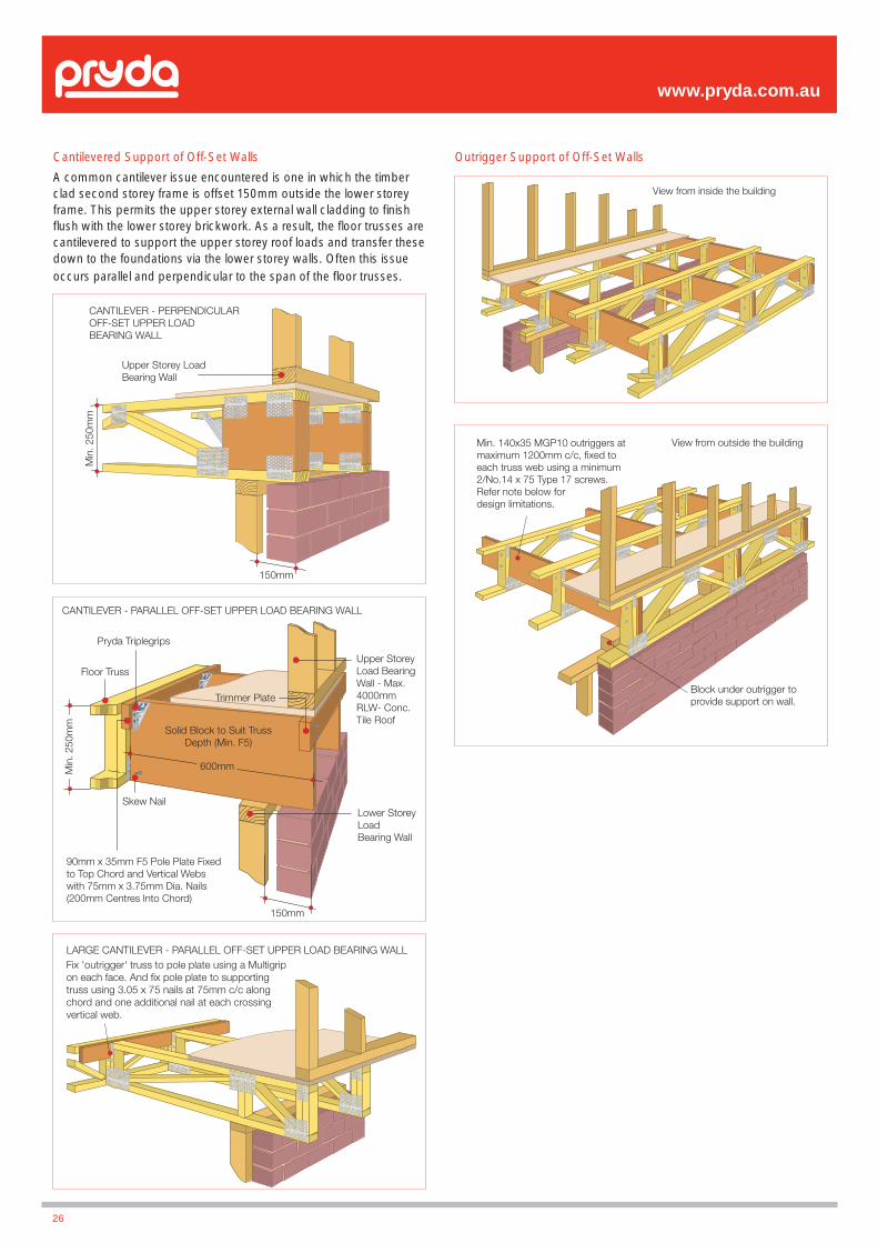
Cantilevered Support of Off-Set Walls
A common cantilever issue encountered is one in which the timber clad second storey frame is offset 150mm outside the lower storey frame. This permits the upper storey external wall cladding to fi nish fl ush with the lower storey brickwork. As a result, the fl oor trusses are cantilevered to support the upper storey roof loads and transfer these down to the foundations via the lower storey walls. Often this issue occurs parallel and perpendicular to the span of the fl oor trusses.
Outrigger Support of Off-Set Walls
www.pryda.com.au
CANTILEVER - PERPENDICULAROFF-SET UPPER LOADBEARING WALL
Upper Storey LoadBearing Wall
150mm
Min
. 250
mm
CANTILEVER - PARALLEL OFF-SET UPPER LOAD BEARING WALL
Pryda Triplegrips
Floor Truss
Trimmer Plate
Solid Block to Suit TrussDepth (Min. F5)
600mm
Skew Nail
Min
. 250
mm
Upper StoreyLoad BearingWall - Max.4000mm RLW- Conc. Tile Roof
Lower StoreyLoadBearing Wall
150mm
90mm x 35mm F5 Pole Plate Fixedto Top Chord and Vertical Webswith 75mm x 3.75mm Dia. Nails(200mm Centres Into Chord)
View from inside the building
Min. 140x35 MGP10 outriggers at maximum 1200mm c/c, fixed to each truss web using a minimum 2/No.14 x 75 Type 17 screws. Refer note below for design limitations.
Block under outrigger to provide support on wall.
View from outside the building
Fix 'outrigger' truss to pole plate using a Multigrip on each face. And fix pole plate to supporting truss using 3.05 x 75 nails at 75mm c/c along chord and one additional nail at each crossing vertical web.
LARGE CANTILEVER - PARALLEL OFF-SET UPPER LOAD BEARING WALL
26

Strong-Backs
Strong-Back beams run perpendicular to the trusses and are used to spread footfall impact loads to adjacent trusses. They are required for all residential fl oors and some of the lighter commercial fl oors.
Strong-Backs are not required for trusses up to 3.5m in span. For trusses 3.5m to 6m span, use one row of Strong-Backs located close to midspan. For trusses above 6m span use 3 rows of Strong-Backs located one row at midspan, and two further rows located at each of the quarter points.
Strong-Backs should be fi xed hard up against the vertical web, but may be fi xed up against the top chord or the bottom chord to suit. Fixings may be hand hammered 75 x 3.75 nails, or power driven 75 x 2.9 nails, or No.14 x 75 Type 17 screws. Screws provide the best performance as they are more rigid, they clamp the timber components together, and they prevent squeaks due to various fl oor components loosening over time.
Where Pryda Span trusses have been used, and there is no vertical web close to the desired location of the Strong-Back, a supplementary vertical web may be nailed to the side of the truss instead with 2 nails to the top chord and to the bottom chord, to provide a fi xing for the Strong-Back.
Splice Detail
In locations where the Strong-Back needs to be joined, either of the following methods may be used:
www.pryda.com.au
LONGREACH STRONG-BACK
Strong-Back Size & Fixingas Per Table
PRYDA SPAN STRONG-BACK
Strong-Back Size& Fixing as Per Table
Nominal truss depth (mm)
Strong-Back depth and grade
(all 35mm thick)
No. of fi xings per connection
200 90 F5/P10 or 70 F17 2/nails or 1/screw
250 120 F5/P10 or 90 F17 3/nails or 2/screws
300 140 F5/P10 or 120 F17 3/nails or 2/screws
350 140 F5/P10 or 120 F17 3/nails or 2/screws
400 140 F5/P10 or 120 F17 3/nails or 2/screws
Note: these are minimum recommended sizes only. Larger Strong-Backs may be used in some instances to achieve better fl oor performances.
STRONG-BACK SPLICE
For fixing refer table above
Strong-Backs should be overlapped by two truss spacing for best performance
ALTERNATIVE STRONG-BACK SPLICE
Splice Strong-Back Togetherwith Cleat on Side
Min. 5/3.75 NailsEach Side of Joist
Table 9 – Strong-Back Size and Beam Selection
27

Non-Aligned Strong-Backs
In cases where different adjacent spans cause the Strong-Backs to be out of alignment, the following detail may be adopted. Vertical blocks of 90 x 35mm are fi xed with 2/3.75 diameter x 75mm nails to both top and bottom chords. Strong-Backs are then fi xed into the side of the block and the preceding vertical web with the number of nails specifi ed in the table.
Strong-Backs Not Required
Strong-Backs may be omitted from fl oors when:
• The fl oor has been designed for live load of 3000 Pa or greater.
• Either 25mm F11 plywood, or 2 layers of 19mm plywood (or better) has been used
In these situations, either the truss will be very stiff due to the high design load, or the fl ooring itself is capable of dissipating human footfall impacts.
Instead, use 90 x 35 F5 (on fl at) lateral ties fi xed to the bottom chord, located 3000mm apart (max.).
STABILITYGeneral
Pryda fl oor trusses must be braced back to their supporting structure for stability in a similar manner to the bracing stipulated by AS1684-2010 for solid deep joists. Use diagonally placed Pryda Strapbrace at 2700mm centres maximum at the ends of trusses and at any internal wall supports. Alternatively, a continuous trimming beam may be used at the end of each truss — see End Type 3 - with diagonal bracing at the end bays only. This bracing may be used as part of a wind bracing system.
Wind Bracing
The wind force on a building must be transmitted through the roof, walls and fl oors to the footings and ultimately to the foundation.
Considering a timber joist or trussed fl oor, the fl oor stability bracing or blocking of walls or bearers will help to transmit these forces and may be suffi cient to resist the entire wind load.
In some instances the fl oor stability bracing or blocking may not be suffi cient and more bracing is required. It is essential therefore that the building designer, design the additional fl oor bracing required and that the builder correctly installs this bracing.
Consideration should be given to AS1684-2010 Section 8 for more thorough analysis of the interaction between the roof, walls and fl oors in forming a complete and adequate bracing system. Also considered is the effect of voids on the performance of bracing diaphragms. If in doubt consult your local Pryda design offi ce.
Lateral Bracing of Floor Trusses Chords
Pryda fl oor trusses are braced laterally at the top chord level by the fl ooring material and at the bottom chord level by the ceiling lining. If there is no ceiling fi xed directly (or by battens) then 90 x 35 binders must be provided on the bottom chord at 3000mm centres maximum.
www.pryda.com.au
WIND
Absence of end-bracing causes racking
WIND
End Bracing provided at max. 2700mm spacing using one of the methods given in page 29.
28
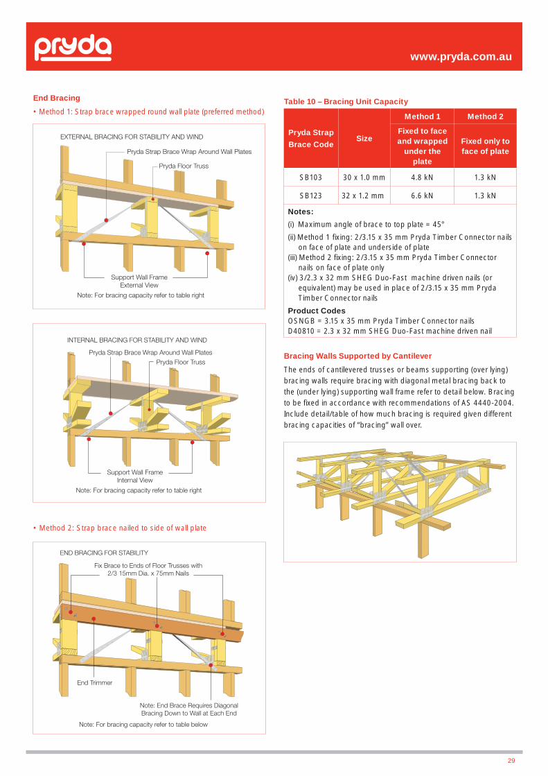
End Bracing
• Method 1: Strap brace wrapped round wall plate (preferred method)
• Method 2: Strap brace nailed to side of wall plate
www.pryda.com.au
EXTERNAL BRACING FOR STABILITY AND WIND
Pryda Strap Brace Wrap Around Wall Plates
Pryda Floor Truss
Support Wall FrameExternal View
Note: For bracing capacity refer to table right
END BRACING FOR STABILITY
Fix Brace to Ends of Floor Trusses with2/3 15mm Dia. x 75mm Nails
End Trimmer
Note: End Brace Requires DiagonalBracing Down to Wall at Each End
Note: For bracing capacity refer to table below
INTERNAL BRACING FOR STABILITY AND WIND
Pryda Strap Brace Wrap Around Wall Plates
Support Wall FrameInternal View
Pryda Floor Truss
Note: For bracing capacity refer to table right
29
Table 10 – Bracing Unit Capacity
Pryda Strap
Brace CodeSize
Method 1 Method 2
Fixed to face and wrapped
under the plate
Fixed only to face of plate
SB103 30 x 1.0 mm 4.8 kN 1.3 kN
SB123 32 x 1.2 mm 6.6 kN 1.3 kN
Notes:
(i) Maximum angle of brace to top plate = 45°
(ii) Method 1 fi xing: 2/3.15 x 35 mm Pryda Timber Connector nails on face of plate and underside of plate
(iii) Method 2 fi xing: 2/3.15 x 35 mm Pryda Timber Connector nails on face of plate only
(iv) 3/2.3 x 32 mm SHEG Duo-Fast machine driven nails (or equivalent) may be used in place of 2/3.15 x 35 mm Pryda Timber Connector nails
Product Codes OSNGB = 3.15 x 35 mm Pryda Timber Connector nailsD40810 = 2.3 x 32 mm SHEG Duo-Fast machine driven nail
Bracing Walls Supported by Cantilever
The ends of cantilevered trusses or beams supporting (over lying) bracing walls require bracing with diagonal metal bracing back to the (under lying) supporting wall frame refer to detail below. Bracing to be fi xed in accordance with recommendations of AS 4440-2004. Include detail/table of how much bracing is required given different bracing capacities of “bracing” wall over.
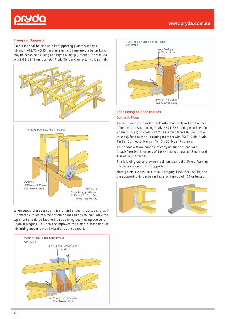
Fixings at Supports
Each truss shall be held onto its supporting plate/bearer by a minimum of 2/75 x 3.15mm diameter nails if preferred a better fi xing may be achieved by using one Pryda Minigrip (Product Code: MG5)with 3/35 x 3.15mm diameter Pryda Timber Connector Nails per tab.
www.pryda.com.au
TYPICAL PLATE SUPPORT FIXING
OPTION 12/75mm x 3.75mmDia. Skewed Nails OPTION 2
Pryda Minigrip with min.3/35mm x 3.15mm Dia.
Pryda Nails Per Tab
2/75mm x 3.75mmDia. Skewed Nails
TYPICAL BEAM SUPPORT FIXINGOPTION 2
Pryda Multigrip orTriple grip
TYPICAL BEAM SUPPORT FIXINGOPTION 1
Self Drilling Screws CSKHeads
2/75mm x 3.75mmDia. Skewed Nails
When supporting trusses on steel or timber beams via top chords it is preferable to restrain the bottom chord using skew nails while the top chord should be fi xed to the supporting beam using screws or Pryda Triplegrips. This practice improves the stiffness of the fl oor by minimizing movement and vibration at the supports.
30
Face Fixing of Floor Trusses
Domestic Floors
Trusses can be supported on loadbearing walls or from the face of beams or bearers using Pryda FB94152 Framing Brackets (for 90mm trusses) or Pryda FB72163 Framing Brackets (for 70mm trusses), fi xed to the supporting member with 35x3.15 dia Pryda Timber Connector Nails or No.12 x 35 Type 17 screws.
These brackets are capable of carrying support reactions (dead+fl oor live) in excess of 9.0 kN, using a total of 18 nails or 6 screws in JD4 timber.
The following tables provide maximum spans that Pryda Framing Brackets are capable of supporting:
Note: Joints are assumed to be Category 1 (AS1720.1:2010) and the supporting timber beam has a joint group of JD4 or better.
Framing Brackets and Fixings
Table 11a – Domestic Loads
Total Fixing into JD4 supporting
beam
Maximum Spans (mm) for Domestic Loads - 1.5 kPa/1.8 kN
(450mm/600mm truss spacing)
450 c/c 600 c/c
8 nails or 4 screws 6400 4800
12 nails or 5 screws 8900 6700
Table 11b – Commercial Loads
Total Fixing into JD4 supporting
beam
Maximum Spans (mm) for Commercial Loads (450mm truss spacing)
3.0 kPa/2.7 kN 5.0 kPa/4.5 kN
12 nails or 5 screws 5200 Not Suitable
18 nails or 6 screws 7600 4900
Note: A permanent load of 0.80 kPa is assumed in the computation of maximum spans. The fl oor truss is assumed simply supported.
INSTALLATIONFor more specifi c information relation to good site practice and workmanship refer to AS 4440-2004 and the Pryda Floor Truss Installation Guide however consideration should be given to the following:
• Documentation for site • Temporary storage
• Transportation to site • Protection from the weather
• Lifting • Modifi cation of trusses and
- Delivery to site manufactured components
- Installation • Connection and fi xing details
• Clearances
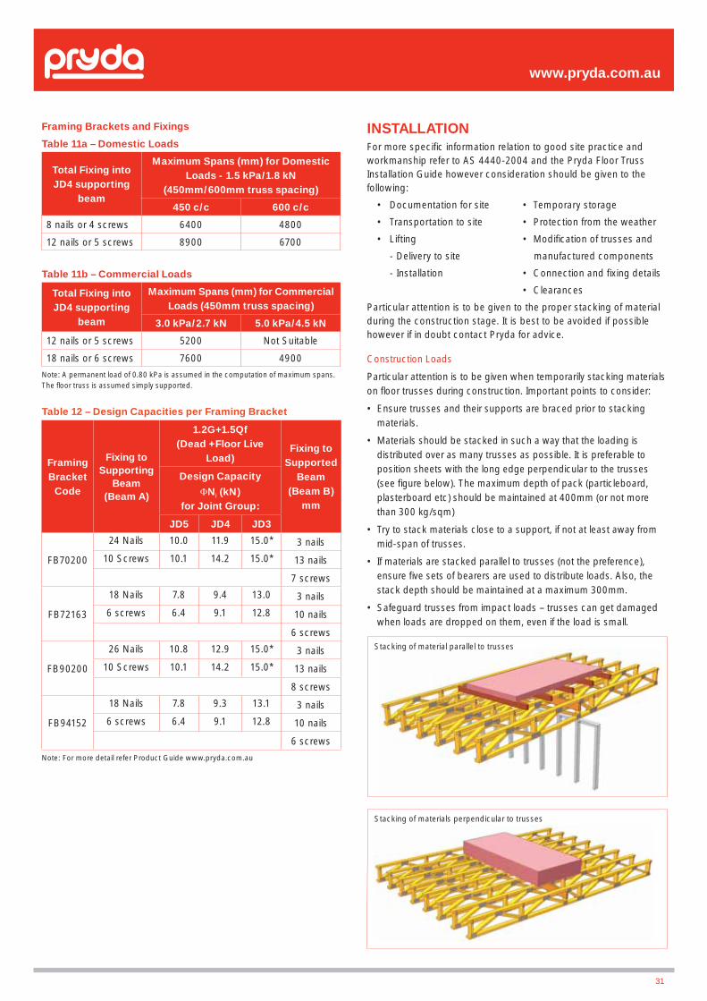
Particular attention is to be given to the proper stacking of material during the construction stage. It is best to be avoided if possible however if in doubt contact Pryda for advice.
Construction Loads
Particular attention is to be given when temporarily stacking materials on fl oor trusses during construction. Important points to consider:
• Ensure trusses and their supports are braced prior to stacking materials.
• Materials should be stacked in such a way that the loading is distributed over as many trusses as possible. It is preferable to position sheets with the long edge perpendicular to the trusses (see fi gure below). The maximum depth of pack (particleboard, plasterboard etc) should be maintained at 400mm (or not more than 300 kg/sqm)
• Try to stack materials close to a support, if not at least away from mid-span of trusses.
• If materials are stacked parallel to trusses (not the preference), ensure fi ve sets of bearers are used to distribute loads. Also, the stack depth should be maintained at a maximum 300mm.
• Safeguard trusses from impact loads – trusses can get damaged when loads are dropped on them, even if the load is small.
www.pryda.com.au
Table 12 – Design Capacities per Framing Bracket
Framing Bracket
Code
Fixing to Supporting
Beam (Beam A)
1.2G+1.5Qf(Dead +Floor Live
Load)Fixing to
Supported Beam
(Beam B)mm
Design Capacity
�Nj (kN) for Joint Group:
JD5 JD4 JD3
FB70200
24 Nails 10.0 11.9 15.0* 3 nails
10 Screws 10.1 14.2 15.0* 13 nails
7 screws
FB72163
18 Nails 7.8 9.4 13.0 3 nails
6 screws 6.4 9.1 12.8 10 nails
6 screws
FB90200
26 Nails 10.8 12.9 15.0* 3 nails
10 Screws 10.1 14.2 15.0* 13 nails
8 screws
FB94152
18 Nails 7.8 9.3 13.1 3 nails
6 screws 6.4 9.1 12.8 10 nails
6 screws
Note: For more detail refer Product Guide www.pryda.com.au
Stacking of material parallel to trusses
Stacking of materials perpendicular to trusses
31
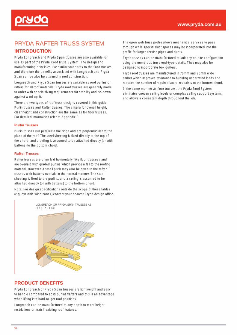
PRYDA RAFTER TRUSS SYSTEMINTRODUCTIONPryda Longreach and Pryda Span trusses are also available for use as part of the Pryda Roof Truss System. The design and manufacturing principles use similar standards to the fl oor trusses and therefore the benefi ts associated with Longreach and Pryda Span can be also be attained in roof construction.
Longreach and Pryda Span trusses are suitable as roof purlins or rafters for all roof materials. Pryda roof trusses are generally made to order with special fi xing requirements for stability and tie-down against wind uplift.
There are two types of roof truss designs covered in this guide – Purlin trusses and Rafter trusses. The criteria for overall height, clear height and construction are the same as for fl oor trusses. For detailed information refer to Appendix F.
Purlin Trusses
Purlin trusses run parallel to the ridge and are perpendicular to the plane of the roof. The steel sheeting is fi xed directly to the top of the chord, and a ceiling is assumed to be attached directly (or with battens) to the bottom chord.
Rafter Trusses
Rafter trusses are often laid horizontally (like fl oor trusses), and are overlaid with graded purlins which provide a fall to the roofi ng material. However, a small pitch may also be given to the rafter trusses with battens overlaid in the normal manner. The steel sheeting is fi xed to the purlins, and a ceiling is assumed to be attached directly (or with battens) to the bottom chord.
Note: For design specifi cations outside the scope of these tables (e.g. cyclonic wind zones) contact your nearest Pryda design offi ce.
PRODUCT BENEFITSPryda Longreach or Pryda Span trusses are lightweight and easy to handle compared to solid purlins/rafters and this is an advantage when lifting into hard-to-get roof positions.
Longreach can be manufactured to any depth to meet height restrictions or match existing roof features.
The open web truss profi le allows mechanical services to pass through while special duct spaces may be incorporated into the profi le for larger service pipes and ducts.
Pryda trusses can be manufactured to suit any on-site confi guration using the numerous truss end-type details. They may also be designed to incorporate box gutters.
Pryda roof trusses are manufactured in 70mm and 90mm wide timber which improves resistance to buckling under wind loads and reduces the number of required lateral restraints to the bottom chord.
In the same manner as fl oor trusses, the Pryda Roof System eliminates uneven ceiling levels or complex ceiling support systems and allows a consistent depth throughout the job.
www.pryda.com.au
LONGREACH OR PRYDA SPAN TRUSSES ASROOF PURLINS
32
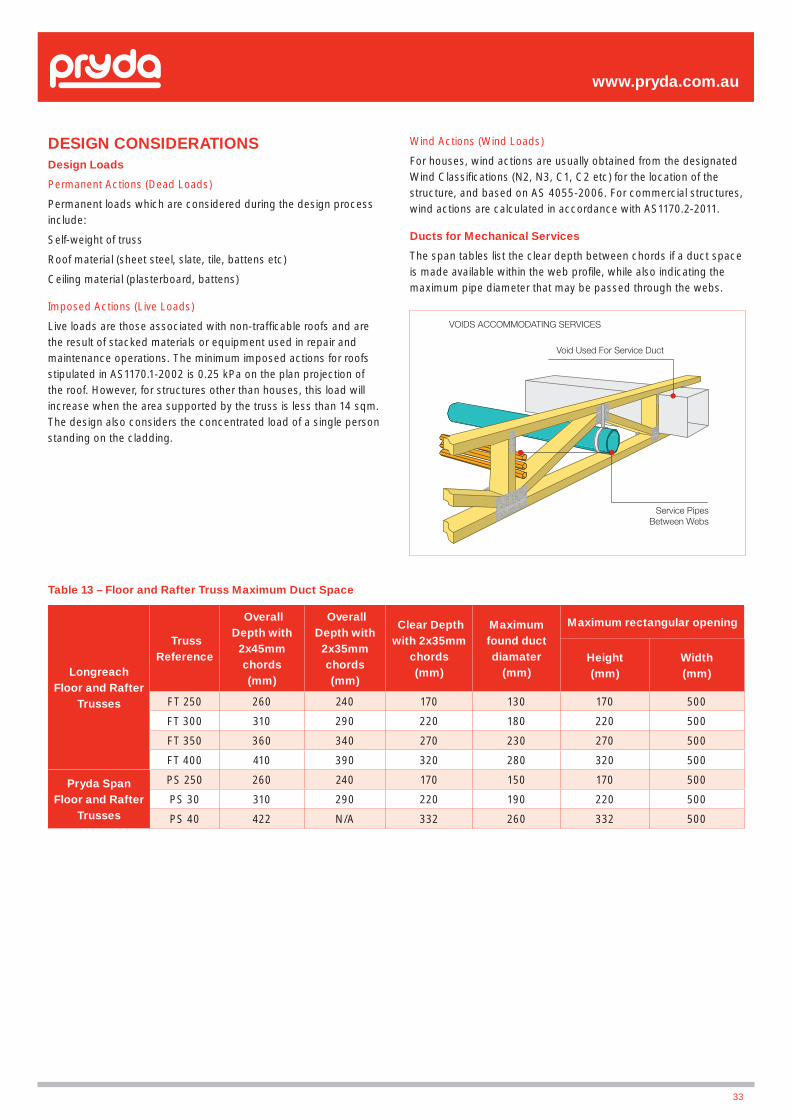
www.pryda.com.au
DESIGN CONSIDERATIONSDesign Loads
Permanent Actions (Dead Loads)
Permanent loads which are considered during the design process include:
Self-weight of truss
Roof material (sheet steel, slate, tile, battens etc)
Ceiling material (plasterboard, battens)
Imposed Actions (Live Loads)
Live loads are those associated with non-traffi cable roofs and are the result of stacked materials or equipment used in repair and maintenance operations. The minimum imposed actions for roofs stipulated in AS1170.1-2002 is 0.25 kPa on the plan projection of the roof. However, for structures other than houses, this load will increase when the area supported by the truss is less than 14 sqm. The design also considers the concentrated load of a single person standing on the cladding.
VOIDS ACCOMMODATING SERVICES
Void Used For Service Duct
Service PipesBetween Webs
Wind Actions (Wind Loads)
For houses, wind actions are usually obtained from the designated Wind Classifi cations (N2, N3, C1, C2 etc) for the location of the structure, and based on AS 4055-2006. For commercial structures, wind actions are calculated in accordance with AS1170.2-2011.
Ducts for Mechanical Services
The span tables list the clear depth between chords if a duct space is made available within the web profi le, while also indicating the maximum pipe diameter that may be passed through the webs.
Table 13 – Floor and Rafter Truss Maximum Duct Space
LongreachFloor and Rafter
Trusses
TrussReference
Overall Depth with
2x45mm chords(mm)
Overall Depth with
2x35mm chords(mm)
Clear Depthwith 2x35mm
chords(mm)
Maximum found duct diamater
(mm)
Maximum rectangular opening
Height(mm)
Width(mm)
FT 250 260 240 170 130 170 500
FT 300 310 290 220 180 220 500
FT 350 360 340 270 230 270 500
FT 400 410 390 320 280 320 500
Pryda SpanFloor and Rafter
Trusses
PS 250 260 240 170 150 170 500
PS 30 310 290 220 190 220 500
PS 40 422 N/A 332 260 332 500
33

FACTORS AFFECTING PERFORMANCEThe performance of Pryda Rafter Trusses may be limited by a number of factors including defl ection under dead load and timber strength capacity under a dead, live or wind actions case.
Defl ection Limits
Longreach and Pryda Span Rafter Trusses are designed according to defl ection limits set out in AS1684.1.
Load Condition Max. Defl ection Ratio
Permanent Action span/300
Imposed Action span/250
Wind Action span/150
Special Loading Conditions
Air conditioning units and other mechanical equipment can add signifi cant loads to rafter trusses. The introduction of an increased truss spacing to incorporate a skylight will also produce a special loading condition. The truss fabricator should be informed of these conditions to accommodate special designs.
STABILITYTop Chord Bracing
The forces generated by resistance to buckling of the top chord and wind loading perpendicular to the span of the trusses must also be transferred back to the supporting structure by steel braces. It is recommended that Pryda Speed Brace or Strap Brace be applied to the top chord in conjunction with adequately spaced roof battens in accordance with AS4440-2004: Installation of Nail-Plated Timber Roof Trusses. The steel brace shall be continuous over the ends of the trusses and be anchored down to the top plate.
Bottom Chord Bracing
Strong-Backs are not required for Longreach or Pryda Span roof trusses. For suspended ceilings, or exposed bottom chords, or where ceiling battens do not provide restraint to bottom chords under wind uplift conditions, it is recommended that bottom chord ties are introduced In accordance with AS4440-2004: Installation of Nail-Plated Timber Roof Trusses. In addition to this, Pryda Speed or Strap Braces shall be fi xed to the truss bottom chords to transfer bracing loads back to the supporting structure according to AS4440-2004: Installation of Nail-Plated Timber Roof Trusses.
In circumstances where the ceiling material and battens do provide effective restraint then bottom chord ties shall not be required.
Cantilever Bracing
Cantilever Bracing Details of Pryda Rafter Truss Systems is as for Pryda Floor Truss Systems. Refer to earlier part of manual and AS4440-2004
Fixing to Supports
Pryda rafter trusses must be fi xed down to the supporting structure using connections that match or exceed the magnitude of the wind uplift forces on each truss. Each truss shall be held onto its supporting plate/bearer by a minimum of 2/75 x 3.15mm skew nails, or one Pryda Minigrip (Product Code: MGS) or Multigrip (Product Code: MG) with 3/35 x 3.15mm nails per tab. Refer to AS1684-2010 for further guidance on fi xings and tie down requirements.
Pryda Rafter Trusses shall also be braced laterally at the ends of the trusses using Pryda Strap Brace at each end of a run of trusses.
www.pryda.com.au
30O-45O
TOP CHORD BRACING AND TIE DOWN FIXING
Brick ParapetWall
End Type 1 Steel Brace
Box Gutter Roof Battens Continuousin this Area
Load BearingWall Frame
Bracing between 30o
and 45o to Top Platewhen Viewed in Plan
Roof BattensContinuous in this Area
45O
BRACING REQUIREMENTS FOR SUSPENDED CEILINGS ANDUNRESTRAINED BOTTOM CHORDS
Steel Brace to Undersideof Bottom Chord toTransfer Bracing Loadsto Structure
Bottom Chord TiesLongreach or
Pryda Span asRoof Trusses
SuspendedCeiling
Note: Refer AS4440-2004 Installation ofNailplated Timber Trusses for Further Guidanceon Bottom Chord Restraint Requirements
34
END BRACING AND TIE DOWN FIXINGLateral Bracing at Ends of Trusses Using Pryda Strap Brace or Equivalent. Cross Brace at Each End of a Run of Trusses or Maximum 3000mm Spacing
Bend Steel Brace Overand Fix with 3/35 x 3.15mm
Nails to Side and 2 Nails Over
Minimum Tie Down 2/75 x 3.15mmSkew Nails or Minigrip/Multigrip
with 3/35 x 3.15mm Nails inEach Tab. Refer AS1684
for Minimum TieDown Requirements

DETAILEnd Confi gurations
The full range of end confi gurations available to fl oor trusses may also be incorporated into Longreach and Pryda Span rafter trusses. In addition to this the end confi guration may be designed to fi t a box gutter or other options as detailed below. These options are available for all truss depths however the dimensions of the box gutter may be limited. Engineering advice should be sought from Pryda.
www.pryda.com.au
FLUSH END
HORIZONTAL SUFFIT OVERHANG
BOX GUTTER AND PARAPET
HORIZONTAL SUFFIT OVERHANG
MANSARD EFFECT
BOX GUTTER
RAKED OVERHANG
35

www.pryda.com.au
APPENDICESAppendix A: Producer Statement
36
Pryda AustraliaA division of ITW Australia Pty Ltd Dandenong Ph (03) 9554 7001 Fax 9554 7000
Floor Truss Design Criteria For Building Permit Application
Client Name: Harry’s Homes
Site Details: Lot 719, No. 53 Clayton Crescent, Rutherford, NT 0800
Nominal Design Criteria:
Building Importance: Residential Flooring: 22mm particieboard Ceiling: 10mm plasterboard Top chord restraints: 300 mm Bottom chord restraints: 600 mm Standard truss spacing: 600 mm Nominal Floor live loads: 1.50 kPa 1.80 kN Floor performance: Nominal
Note: Ceiling lining must be fi xed to the bottom chords of trusses with nails or screws at maximum 600mm centres.
The truss designs for this job have been determined using computer software provided by Pryda Australia, using sound and widely accepted engineering principles. In particular, loadings and designs and are performed in accordance with the Standards adopted by primary reference in the National Construction Code (NCC 2011), Volume One, A1.3 and Volume Two, Part 1.4.
In addition, the following secondary referenced Australian Standards also apply:
AS 1649-2001 Timber - Methods of test for mechanical fasteners and connectors - Basic working loads and characteristic strengths
AS 1684.1-1999 Residential timber - framed construction, Part 1, Design Criteria
All trusses shall be manufactured in accordance with the fabrication specifi cations provided by Pryda, and installed, connected and braced in accordance with the recommendations given in - : Pryda’s Guide to Installation and any other supplementary details that may be provided.
Name: Position:
Signed: Date:
Page 1Date: 11.29am 5-1-2011
Ver 3.0.4
Job Ref: 7889602Producer Statement
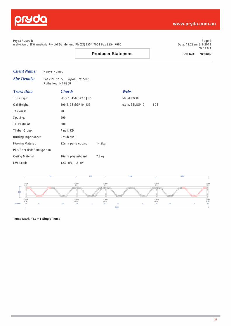
www.pryda.com.au
37
Pryda AustraliaA division of ITW Australia Pty Ltd Dandenong Ph (03) 9554 7001 Fax 9554 7000
Client Name: Harry’s Homes
Site Details: Lot 719, No. 53 Clayton Crescent, Rutherford, NT 0800
Truss Data Chords Webs
Truss Type: Floor 1. 45MGP10 JD5 Metal PW30
Oall Height: 300 2. 35MGP10 JD5 u.o.n. 35MGP10 JD5
Thickness: 70
Spacing: 600
TC Restraint: 300
Timber Group: Pine & KD
Building Importance: Residential
Flooring Material: 22mm particleboard 14.8kg
Plus Specifi ed: 3.00kg/sq.m
Ceiling Material: 10mm plasterboard 7.2kg
Live Load: 1.50 kPa; 1.8 kW
Truss Mark FT1 > 1 Single Truss
Page 2Date: 11.29am 5-1-2011
Ver 3.0.4
Job Ref: 7889602Producer Statement

www.pryda.com.au
38
Appendix B: Typical Layout
www.pryda.com.au
Appendix C: Detailers Guide / Check ListThis is intended to be used as a basic guide only, if in doubt contact
an authorized Pryda fabricator or the engineering Department of
Pryda Australia
1. Confi rm the imposed actions (fl oor live loads) -uniformly
distributed load (kPa) and concentrated load (kN). This is
particularly important for commercial jobs
2. Confi rm the fl oor fi nishes i.e. fl oor recess in wet areas, shower
base, etc.
3. Confi rm any additional loads:
(a) Kitchen - island benches, stone bench tops etc
(b) Wet areas - fl oor tiles, wall tiles, large baths, spa baths,
vanities etc
(c) Storage units, book shelves, water beds, pianos, billiard
tables etc.
4. Ensure fl ooring material is adequate to satisfy applied live loads
and truss spacing.
Note: Generally a warning message will pop-up in Pryda Buildi if
the selected fl ooring material is not suitable.
5. Trusses under walls with wall tiles should be considered
6. Trusses supporting load bearing walls:
(a) For walls spanning across trusses– ensure a Critical Vertical
Web is provided at this location and the correct point loads
are applied.
(b) For walls spanning along a truss- ensure correct point
loads are applied at every panel point. Double trusses may
be considered to satisfy serviceability requirements.
7. A more stringent serviceability requirement may be considered
for brittle surfaces such as stone and tiles.
8. Determine location of all critical plumbing services. I.e. toilets,
shower drains etc. and ensure trusses are detailed (web profi le,
truss spacing etc) to accommodate these service pipes.
9. Waling plate design and con nections to support trusses must
be designed by builder’s Consulting Engineer. Seek advice if in
doubt. Do not assume nominal fi xing of waling plates without
considering how the loads are supported.
10. Dynamic performance (spring and bounce) is likely to be
increased when fl oor trusses/joists are supported on structural
beams. This aspect must be given consideration.
11. Screw fi xing of Strong-Backs to vertical webs is recommended
for more consistent performance. Nail fi xed Strong-Backs
should be tight fi tting with no gaps in the connection to the
vertical webs.
12. Strongback splice location and methods of connection should
be highlighted to ensure correct installation.
13. Solid block or continuous trimmer is to be provided under
all concentrated point loads. I.e. jam studs supporting load-
bearing lintels and studs supporting concentrated loads.
14. Simplify and rationalize fl oor truss connections to supporting
beams to reduce the risk of errors during installation.
15. Continuous span fl oor truss will behave much better than single
span trusses.
When a situation arises where an existing continuous span truss
is required to be trimmed back, check the remaining single
span for adequate performance. Don’t assume the remaining
single span will perform correctly
16. Unless specifi cally required for a particular layout the Pryda
Buildi default should be set to “Force diagonal web at Gap” for
better truss performance.
17. Floor trusses used in external decking/balcony situations must
be fully sealed and made 100% waterproof. If this cannot
be achieved then avoid using fl oor trusses in these areas
and substitute with solid joists with the appropriate grade of
durability. This should be addressed at the quotation stage.
18. Under no circumstance shall the builder or installer be allowed
to modify fl oor trusses or their connections without prior
approval from truss designer or Pryda Engineers.
39
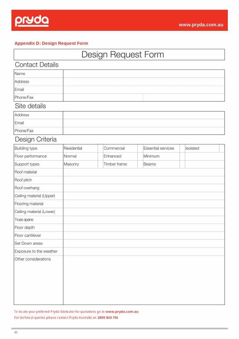
Appendix D: Design Request Form
www.pryda.com.au
40
Name
Address
Phone/Fax
Address
Phone/Fax
Building type Residential Commercial Essential services Isolated
Floor performance Normal Enhanced Minimum
Support types Masonry Timber frame Beams
Roof material
Roof pitch
Roof overhang
Ceiling material (Upper)
Flooring material
Ceiling material (Lower)
Truss spans
Floor depth
Floor cantilever
Set Down areas
Exposure to the weather
Other considerations
Design Request FormContact Details
Site details
Design Criteria
To locate your preferred Pryda fabricator for quotations go to www.pryda.com.au
For technical queries please contact Pryda Australia on 1800 810 741
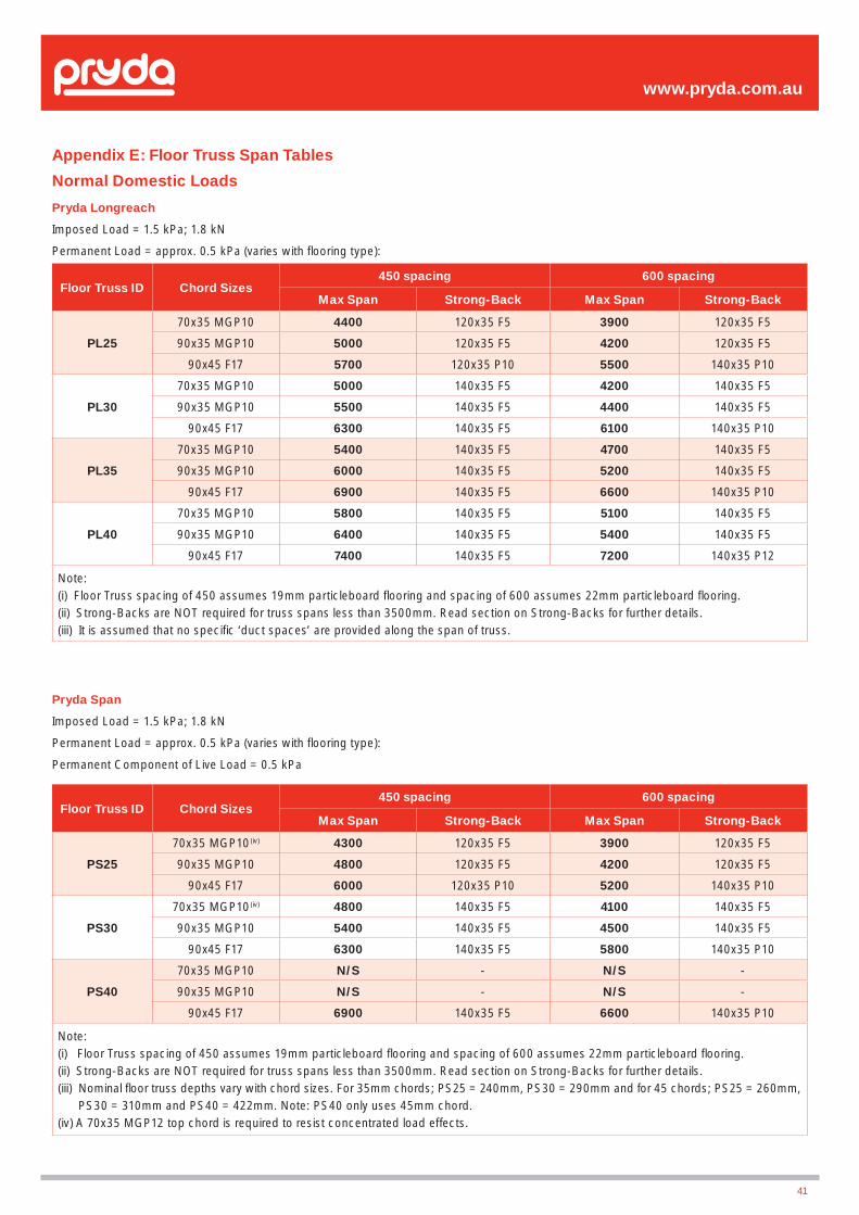
www.pryda.com.au
41
Appendix E: Floor Truss Span Tables
Normal Domestic Loads
Pryda Longreach
Imposed Load = 1.5 kPa; 1.8 kN
Permanent Load = approx. 0.5 kPa (varies with fl ooring type):
Permanent Component of Live Load = 0.5 kPa
Pryda Span
Imposed Load = 1.5 kPa; 1.8 kN
Permanent Load = approx. 0.5 kPa (varies with fl ooring type):
Permanent Component of Live Load = 0.5 kPa
Floor Truss ID Chord Sizes450 spacing 600 spacing
Max Span Strong-Back Max Span Strong-Back
PL25
70x35 MGP10 4400 120x35 F5 3900 120x35 F5
90x35 MGP10 5000 120x35 F5 4200 120x35 F5
90x45 F17 5700 120x35 P10 5500 140x35 P10
PL30
70x35 MGP10 5000 140x35 F5 4200 140x35 F5
90x35 MGP10 5500 140x35 F5 4400 140x35 F5
90x45 F17 6300 140x35 F5 6100 140x35 P10
PL35
70x35 MGP10 5400 140x35 F5 4700 140x35 F5
90x35 MGP10 6000 140x35 F5 5200 140x35 F5
90x45 F17 6900 140x35 F5 6600 140x35 P10
PL40
70x35 MGP10 5800 140x35 F5 5100 140x35 F5
90x35 MGP10 6400 140x35 F5 5400 140x35 F5
90x45 F17 7400 140x35 F5 7200 140x35 P12
Note:(i) Floor Truss spacing of 450 assumes 19mm particleboard fl ooring and spacing of 600 assumes 22mm particleboard fl ooring.(ii) Strong-Backs are NOT required for truss spans less than 3500mm. Read section on Strong-Backs for further details.(iii) It is assumed that no specifi c ‘duct spaces’ are provided along the span of truss.
Floor Truss ID Chord Sizes450 spacing 600 spacing
Max Span Strong-Back Max Span Strong-Back
PS25
70x35 MGP10(iv) 4300 120x35 F5 3900 120x35 F5
90x35 MGP10 4800 120x35 F5 4200 120x35 F5
90x45 F17 6000 120x35 P10 5200 140x35 P10
PS30
70x35 MGP10(iv) 4800 140x35 F5 4100 140x35 F5
90x35 MGP10 5400 140x35 F5 4500 140x35 F5
90x45 F17 6300 140x35 F5 5800 140x35 P10
PS40
70x35 MGP10 N/S - N/S -
90x35 MGP10 N/S - N/S -
90x45 F17 6900 140x35 F5 6600 140x35 P10
Note:(i) Floor Truss spacing of 450 assumes 19mm particleboard fl ooring and spacing of 600 assumes 22mm particleboard fl ooring.(ii) Strong-Backs are NOT required for truss spans less than 3500mm. Read section on Strong-Backs for further details.(iii) Nominal fl oor truss depths vary with chord sizes. For 35mm chords; PS25 = 240mm, PS30 = 290mm and for 45 chords; PS25 = 260mm, PS30 = 310mm and PS40 = 422mm. Note: PS40 only uses 45mm chord.(iv) A 70x35 MGP12 top chord is required to resist concentrated load effects.

www.pryda.com.au
42
Commercial Offi ce Loads
Pryda Longreach
Dead Load = Nominal +0.50 kPa, Live Load = 3.0 kPa; 2.7 kN; Truss Spacing = 450 c/c
Pryda Span
Dead Load = Nominal +0.50 kPa, Live Load = 3.0 kPa; 2.7 kN; Truss Spacing = 450 c/c
Floor Truss ID Chord SizesMax Span for
450 c/c
PL25/3
90x35 MGP10 2800
90x45 MGP12 4900
90x45 F17 5200
PL30/3
90x35 MGP10 3900
90x45 MGP12 5600
90x45 F17 5800
PL35/3
90x35 MGP10 4200
90x45 MGP12 6300
90x45 F17 6400
PL40/3
90x35 MGP10 4600
90x45 MGP12 6800
90x45 F17 6900
PL45/3
90x35 MGP10 4900
90x45 MGP12 7300
90x45 F17 7500
(i) Assumes 22mm particleboard fl ooring, using 565mm standard web lengths
Floor Truss ID Chord SizesMax Span for
450 c/c
PL25/3
90x35 MGP10 2500
90x45 MGP12 4600
90x45 F17 4800
PL30/3
90x35 MGP10 3600
90x45 MGP12 5300
90x45 F17 5500
PL35/3
90x35 MGP10 N/S
90x45 MGP12 6300
90x45 F17 6300
Notes: Floor Truss Span Tables
i. Nominal Permanent Loads - The span tables provided in the following pages are based on a nominal permanent load of approximately 0.25 kPa to 0.35 kPa. This takes into account the weight of fl ooring material, ceiling material, light weight fl oor coverings like carpets and any insulation. Some examples are given below for easy understanding.
Ex1: 19mm particleboard as fl ooring material = 13.2 kg/m²
10mm plasterboard as ceiling material = 7.2 kg/m²
Carpets as fl oor covering = 3.0 kg/m²
Any insulation = 1.0 kg/m²
TOTAL = 24.4 kg/m² = 0.24 kPa
Ex2: 22mm particleboard as fl ooring material = 14.8 kg/m²
13mm plasterboard as ceiling material = 8.5 kg/m²
12mm timber as fl oor covering = 7.0 kg/m²
Any insulation = 1.0 kg/sqm²
TOTAL = 31.3 kg/m² = 0.31 kPa
The self weight of the fl oor truss itself is considered separately in the design, and is not part of the 0.40 kPa indicated here. Note: In addition to the dead loads, a permanent component of the imposed (live) load of 0.50 kPa is also considered in the design.
ii. Flooring Material – 19mm particleboard for 450 c/c and 22mm particleboard for 600 c/c are assumed as the fl ooring material supporting domestic loads. And, 22mm particleboard fl ooring is assumed for offi ce loads at 450 truss spacing.
iii. Strong-Backs – are not required for truss spans less than 3500mm. Read the section on Strong-Backs for further details.
iv. Duct Spaces – the design assumes that ducts and pipes are taken through the natural gaps in the truss, and no specifi c duct spaces are provided. If duct spaces are required, the truss manufacturer should be informed at the design stage with specifi c size and locations. Accordingly, the maximum spans given here may get reduced slightly.
v. Top Chord Panel Lengths – it is assumed that standard 565mm lengths are used for diagonal webs. The top chord panel lengths would then vary with changing truss depth. This is of particular importance to fl oor trusses in commercial jobs with large concentrated loads.
vi. Dynamic Performance – the maximum spans in the given span tables are generated for ‘normal’ conditions, meaning that the natural frequency is maintained at a minimum 8.0 Hz. The performance of the fl oor is also infl uenced by many other factors, and for further details read the note on the subject in pages 12 and 13
Special Note: The above tables are intended as a guide only. The fi nal design of trusses will be carried out by a Pryda Truss Manufacturer for a given project using proprietary software developed by Pryda Australia.
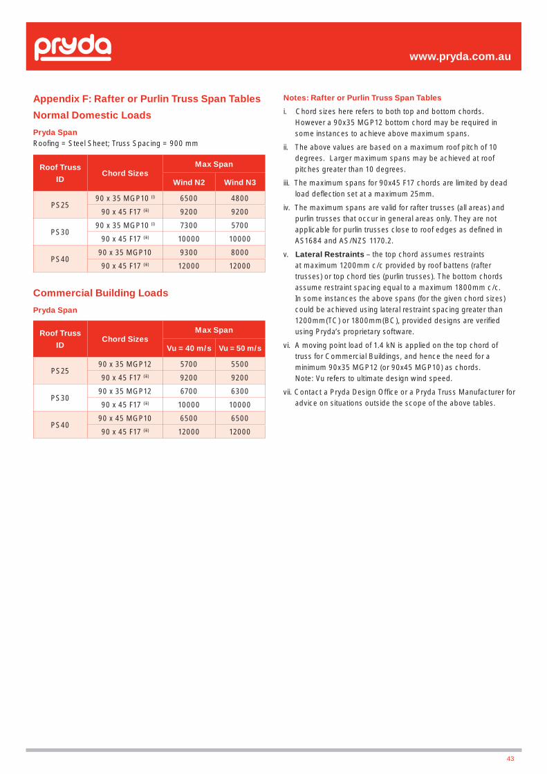
www.pryda.com.au
43
Roof Truss
IDChord Sizes
Max Span
Wind N2 Wind N3
PS2590 x 35 MGP10 (i) 6500 4800
90 x 45 F17 (iii) 9200 9200
PS3090 x 35 MGP10 (i) 7300 5700
90 x 45 F17 (iii) 10000 10000
PS4090 x 35 MGP10 9300 8000
90 x 45 F17 (iii) 12000 12000
Roof Truss
IDChord Sizes
Max Span
Vu = 40 m/s Vu = 50 m/s
PS2590 x 35 MGP12 5700 5500
90 x 45 F17 (iii) 9200 9200
PS3090 x 35 MGP12 6700 6300
90 x 45 F17 (iii) 10000 10000
PS4090 x 45 MGP10 6500 6500
90 x 45 F17 (iii) 12000 12000
Appendix F: Rafter or Purlin Truss Span Tables
Normal Domestic Loads
Pryda SpanRoofi ng = Steel Sheet; Truss Spacing = 900 mm
Commercial Building Loads
Pryda Span
Notes: Rafter or Purlin Truss Span Tables
i. Chord sizes here refers to both top and bottom chords. However a 90x35 MGP12 bottom chord may be required in some instances to achieve above maximum spans.
ii. The above values are based on a maximum roof pitch of 10 degrees. Larger maximum spans may be achieved at roof pitches greater than 10 degrees.
iii. The maximum spans for 90x45 F17 chords are limited by dead load defl ection set at a maximum 25mm.
iv. The maximum spans are valid for rafter trusses (all areas) and purlin trusses that occur in general areas only. They are not applicable for purlin trusses close to roof edges as defi ned in AS1684 and AS/NZS 1170.2.
v. Lateral Restraints – the top chord assumes restraints at maximum 1200mm c/c provided by roof battens (rafter trusses) or top chord ties (purlin trusses). The bottom chords assume restraint spacing equal to a maximum 1800mm c/c. In some instances the above spans (for the given chord sizes) could be achieved using lateral restraint spacing greater than 1200mm(TC) or 1800mm(BC), provided designs are verifi ed using Pryda’s proprietary software.
vi. A moving point load of 1.4 kN is applied on the top chord of truss for Commercial Buildings, and hence the need for a minimum 90x35 MGP12 (or 90x45 MGP10) as chords. Note: Vu refers to ultimate design wind speed.
vii. Contact a Pryda Design Offi ce or a Pryda Truss Manufacturer for advice on situations outside the scope of the above tables.
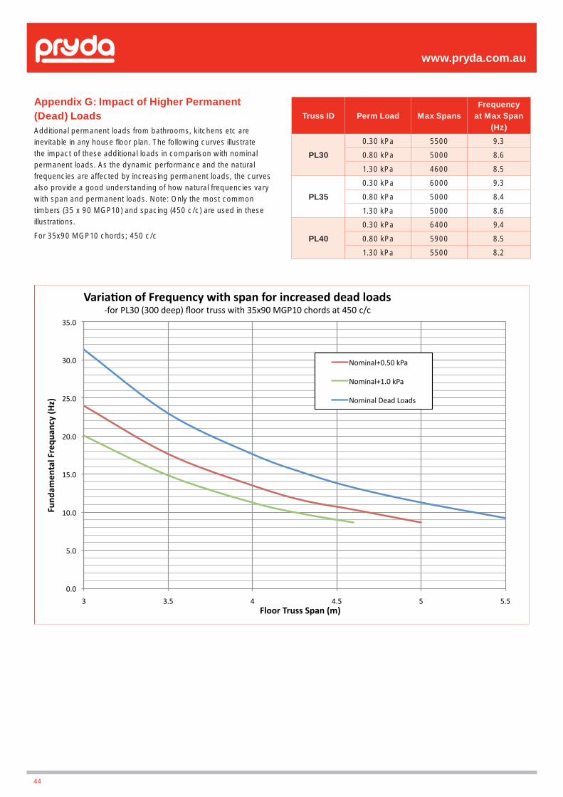
Appendix G: Impact of Higher Permanent (Dead) Loads
Additional permanent loads from bathrooms, kitchens etc are inevitable in any house fl oor plan. The following curves illustrate the impact of these additional loads in comparison with nominal permanent loads. As the dynamic performance and the natural frequencies are affected by increasing permanent loads, the curves also provide a good understanding of how natural frequencies vary with span and permanent loads. Note: Only the most common timbers (35 x 90 MGP10) and spacing (450 c/c) are used in these illustrations.
For 35x90 MGP10 chords; 450 c/c
www.pryda.com.au
Truss ID Perm Load Max SpansFrequency
at Max Span (Hz)
PL30
0.30 kPa 5500 9.3
0.80 kPa 5000 8.6
1.30 kPa 4600 8.5
PL35
0.30 kPa 6000 9.3
0.80 kPa 5000 8.4
1.30 kPa 5000 8.6
PL40
0.30 kPa 6400 9.4
0.80 kPa 5900 8.5
1.30 kPa 5500 8.2
44

www.pryda.com.au
45

www.pryda.com.au
46
NOTES


www.pryda.com.au
3
:: www.pryda.com.au
Melbourne (Head Offi ce)
2-10 Nina Link, Dandenong South, Victoria 3175 Australia.
Tel: 1800 810 741Fax: 1300 657 054Email: [email protected]
Contact Pryda
All enquiries to Melbourne Head Offi ce