Empire State Building. Estructura y proceso de Construcción.
HORMIGÓN Y ACERO | 9
Proyecto y construcción de la estructura de los Teatros del Canal,Centro de las Artes Escénicas de la Comunidad de MadridStructural design and construction for the “Teatros del Canal”, Madrid Centre for the Performing ArtsJulio Martínez Calzón(1) y Álvaro Serrano Corral(2)
Recibido | Received: 06-11-2008Aceptado | Accepted: 10-12-2008
(1) Dr. Ingeniero de Caminos, Canales y Puertos. Director. MC2 Estudio de Ingeniería (Madrid, España).(2) Ingeniero de Caminos, Canales y Puertos. MC2 Estudio de Ingeniería (Madrid, España).
Persona de contacto / Corresponding author: [email protected]
Volumen 60 , nº 251, 9-34 | enero-marzo 2009 | ISSN: 0439-5689
Resumen
Se describe el proyecto y construcción de la estructura del Centro de Artes Escénicas de la Comunidad de Madrid,Teatros del Canal, del arquitecto Juan Navarro Baldeweg. Esta estructura se compone de tres edificios: dos teatros
y un centro coreográfico con estructuras de hormigón armado y pretensado, metálicas y mixtas. Los edificios se carac-terizan por tener su estructura colgada de las zonas superiores mediante pantallas y losas en voladizo, de hormigónpretensado, de hasta 18 m. El proyecto de una estructura evolutiva de esta magnitud lleva aparejado la utilización desistemas especiales de análisis que, igualmente, se describen a continuación.
Palabras clave: teatro, hormigón pretensado, pantallas, estructura colgada, estructura mixta, fachada, postproceso.
Abstract
In the article, the structural project and construction of the Teatros del Canal, Madrid Centre for the Performing Arts, desig-ned by architect Juan Navarro Baldeweg, are described. The building can be divided in three pieces: two theatres and a chore-
ographic centre with reinforced and prestressed concrete, composite and steel structures. The buildings have a hung structurefrom the upper zones by means of walls structure. They also have prestressed concrete slabs cantilevering until 18 m. The struc-tural project of this kind of structures needs the use of special analyses systems that are also described.
Key words: theatre, prestressed concrete, shear walls, suspended structure, composite structure, façade, postprocessing.Re
aliz
acio
nes
y Pr
oyec
tos
Documento descargado de www.e-ache.com el 27/01/2022

10 | HORMIGÓN Y ACERO
Volumen 60 , nº 251, 9-34 | enero-marzo 2009 | ISSN: 0439-5689 J. Martínez Calzón y Á. Serrano
Proyecto y construcción de la estructura de los Teatros del Canal,…
1. INTRODUCCIÓN Y ASPECTOS GENERALES
Los Teatros del Canal se sitúan en Madrid, en la con-fluencia de las calles Bravo Murillo y Cea Bermúdez,ocupando un solar de 8750 m2 antiguamente utilizadopor el Canal de Isabel II (compañía suministradora delagua en Madrid) como almacén y taller.
El edificio surge como una necesidad de la ciudad deMadrid, que requería un espacio escénico adecuado, mo-derno y funcional para poder acoger a las más exigen-tes producciones teatrales, y es el resultado de un con-curso restringido, convocado en junio del año 2000 porla Comunidad de Madrid, con el patrocinio del Canalde Isabel II.
De este concurso salió ganadora, por unanimidad, lapropuesta del arquitecto cántabro Juan NavarroBaldeweg, que contó con MC2 Estudio de Ingenieríapara llevar a cabo el proyecto estructural necesario paradesarrollar su diseño arquitectónico [1].
En el año 2002, la obra civil del edificio fue adjudicadaa la UTE formada por las empresas Dragados (entoncesACS) y OHL. Posteriormente, para realizar el equipa-miento escénico de los teatros, a estas dos empresas seuniría la firma ThyssenKrupp Elevadores.
El concepto arquitectónico del proyecto se basaba encrear un hito artístico y arquitectónico, “rico formal-mente y con una vitalidad intrínseca que hiciera brillary animara la encrucijada de las calles Bravo Murillo yCea Bermúdez”, al decir de Juan Navarro Baldeweg, yque además se abriera a las extensas zonas verdes quese sitúan a su frente (Fig. 1).
1. INTRODUCTION AND GENERAL ASPECTS
The Teatros del Canal building, is located in Madrid, in theconfluence of the streets Bravo Murillo and Cea Bermúdez,occupying a plot of 8750 m2 formerly used by the Canal deIsabel II (water supplying company in Madrid) like ware-house and factory.
Madrid has for many years lacked a modern and functionalcentre for the performing arts and in the majority of occa-sions the city has had to resort to nineteenth century the-atres of great architectural merit but offering little in theway of comfort, functionality, visibility and acoustics oreven location for the more demanding theatre productions ofthe present and future.
In order to overcome this shortfall and obtain a comfortable,modern and functional centre, the Comunidad de Madrid(Madrid Regional Council), put out to restricted tender inJune 2000 a project for the Teatros del Canal (Canal Thea-tres) Centre for the Performing Arts.
The successful tender by unanimous vote was the projectpresented by the architect Juan Navarro Baldeweg whoentrusted MC2 Estudio de Ingeniería with the preparationof the audacious structural project necessary to implementthe architectural design [1].
In 2002, the civil works of the building was adjudged to theJoint Venture formed by Dragados (then ACS) and OHL.Later, the ThyssenKrupp Elevadores company joined theaforementioned firms to assemble the stage equipment of thetheatres.
The architectonic concept of the project was based on creatingan artistic and architectonic, “formally rich and with an
Real
izac
ione
s y
Proy
ecto
s
Figura 1. Situación y entorno del edificio.Figure 1. Situation and surroundings of the building
Documento descargado de www.e-ache.com el 27/01/2022

HORMIGÓN Y ACERO | 11
J. Martínez Calzón y Á. SerranoVolumen 60 , nº 251, 9-34 | enero-marzo 2009 | ISSN: 0439-5689
Structural design and construction for the “Teatros del Canal”…
intrinsic vitality landmark that made shine and animated theBravo Murillo and Cea Bermúdez streets confluence”, accord-ing to Juan Navarro Baldeweg’s words, and in addition openeditself to the extensive green zones located at its front (Fig. 1).
The functionality of the building dedicated to the theatreactivity, demanded integration and segregation. The urbanlife had to feel attracted by the theatre activity, and simulta-neously, had to consider a certain discontinuity to protectthe nucleus of the work, that by its nature is not connectedwith the surrounding urban reality [2].
This circumstance was formalized by means of the integra-tion and continuity of the street in the access ground level;and the segregation, by the elevation on height of the rest ofthe architectonic program. Then, this forced the transparen-cy and continuity of the public space inside the building thatinvites the citizen to its participation, but always protectingthe centre of the theatre activity in an upper level (Fig. 2).
These conceptual decisions implied a complex interrelationbetween the building volumes and empty spaces, that later
La funcionalidad del edificio, dedicado a la actividadteatral, exigía integración y segregación. La vida urba-na debía sentirse atraída por la actividad teatral, y a lavez, debía plantearse una cierta discontinuidad paraproteger el núcleo de la obra, que por naturaleza, resul-ta ajeno, en gran medida, a la realidad ciudadana cir-cundante [2].
Esta última dicotomía se formalizó mediante la integra-ción y continuidad de la calle en el nivel de las plantasbajas de acceso; y la segregación, por elevación en alturadel resto del programa arquitectónico, que llevaba consi-go la transparencia y continuidad del espacio público enel interior del edificio, y que invita a la participación alviandante, pero siempre resguardando el centro de laactividad teatral en un nivel superior (Fig. 2).
Estas decisiones conceptuales implicaban una complejainterrelación entre volúmenes edificatorios y vacíos,que se traduciría posteriormente en un proyecto arqui-tectónico fuertemente imbricado en la estructura resis-tente que lo soporta [3] (Fig. 3).
Real
izac
ione
s y
Proy
ecto
s
Figura 2. Conceptos iniciales del proyecto arquitectónico.Figure 2. First architectural concepts.
Figura 3. Primera maqueta del proyecto.Figure 3. Architectural model.
Documento descargado de www.e-ache.com el 27/01/2022

12 | HORMIGÓN Y ACERO
Volumen 60 , nº 251, 9-34 | enero-marzo 2009 | ISSN: 0439-5689 J. Martínez Calzón y Á. Serrano
Proyecto y construcción de la estructura de los Teatros del Canal,…
2. DESCRIPCIÓN GENERAL DEL EDIFICIO
El edificio se compone de tres piezas bien diferenciadasfuncionalmente por el objeto de su uso, y arquitectónica-mente por los volúmenes que dichas piezas generan y losespacios intermedios que las mismas determinan [5]; asi-mismo, estos volúmenes son independientes estructural-mente. La superficie construida es de 35.520 m2 de los queson útiles aproximadamente 29.400 m2 (Fig. 4).
El Teatro Principal constituye el volumen central deledificio. Consiste en un gran escenario de 40 m deancho y 20 m de fondo de escena, y una sala para 850espectadores situados en dos niveles. El foso de orques-ta, usualmente cerrado, dispone de una plataformamóvil que permite, en caso necesario, acoger a unaorquesta de hasta 80 músicos. Sobre esta sala principal,el teatro cuenta con una amplia zona de ensayos de 28x 25 m2 completamente diáfana.
Una segunda sala de carácter polivalente, denominadaTeatro Configurable, se sitúa adyacente al TeatroPrincipal. Este espacio se ha diseñado para poder confi-gurarse espacial y artísticamente con total libertad enfunción del espectáculo que se represente en cadamomento. Dispone de techo y suelo técnicos, que per-miten situar el escenario en el centro de la sala o enposición frontal y distribuir a los espectadores en laforma que más convenga al espectáculo mediante eluso de gradas telescópicas. Su aforo puede variar entre450 y 725 personas (Figs. 5 y 6).
El acceso, tanto al Teatro Principal, como al Teatro Con-figurable, se realiza por el nivel de calle, que en la idea
would lead to an architectonic project strongly overlappedwith its resistant structure [3] (Fig. 3).
2. GENERAL DESCRIPTION
The building is composed of three areas which are clearly dif-ferentiated both in terms of use and architecture, by theforms of the buildings and the intermediate areas defined bythe same. These volumes are structurally independent. Thetotal built area is 35.520 m2 with 29.400 m2 being usablespace.
The Main Theatre forms the central part of the building andhas seating for 850 spectators set on two levels and a 40 mwide and 20 m deep stage. The orchestra pit, usually closed,is equipped with a moving platform to house up to 80 musi-cians. A broad and complete open plan rehearsal area of 28 x25 m2 is set over the main theatre.
A second multi-purpose hall, called Configurable Theatre,has also been built which may be freely configured to suit theperformance. This theatre area has technical floor and ceilingwhich allow the movement of the stage into the centre of thetheatre or in a frontal position and to distribute the audiencein different seating arrangements by means of telescopic orsliding stalls which, in accordance with arrangement, mayseat between 450 and 725 spectators (Figs. 5 y 6).
The access, in both theatres, is made at the street level, thatin the previously mentioned architectonic concept, is anopen and permeable space, without supports nor other ele-
Real
izac
ione
s y
Proy
ecto
s
Figura 4. Imagen virtual de los edificios: Teatro Configurable, Teatro Principal y Centro Coreográfico (de izquierda a derecha)
Figure 4. Infography of the buildings: Configurable Theatre, Main Theatre and Choreographic Centre (from left to the right).
Documento descargado de www.e-ache.com el 27/01/2022

HORMIGÓN Y ACERO | 13
J. Martínez Calzón y Á. SerranoVolumen 60 , nº 251, 9-34 | enero-marzo 2009 | ISSN: 0439-5689
Structural design and construction for the “Teatros del Canal”…
ments that migth suppose a discontinuity in the perceptionof the space. In this way the ceilings of these zones are greatcantilever slabs, which pretend to be solely supported at theopposite zone to the entrance.
The third section of the building is formed by theChoreographic Centre which is dedicated to the developmentand promotion of dance as a performing art, with its dancerooms, classrooms, studios, dressing rooms, rehearsal areas,document department and dance promotion office.
These three areas are connected at the rear by a commonservice area which allows the individual or combined use ofthe halls; and in its lower part by an underground levelshared by the three pieces with parking uses, warehouse, fac-tories and other dependencies.
arquitectónica anteriormente expuesta, es un espacioabierto y permeable, sin soportes ni otros elementosque supongan una discontinuidad en la percepción delespacio. De este modo los techos de estos ámbitos sonunos grandes voladizos, que aparentan estar únicamen-te apoyados en el fondo opuesto a la entrada.
La tercera componente del edificio consiste en unCentro Coreográfico, dedicado al desarrollo y promo-ción de la danza como expresión artística, con 12 salasde baile, aulas, estudios, camerinos, salas de entrena-miento, una unidad de documentación y una oficinapara la promoción y difusión de la danza.
Estas tres zonas están unidas en su parte dorsal por unazona común de servicios, que permite la utilización de
Real
izac
ione
s y
Proy
ecto
s
Figuras 5. Plantas esquemáticas de los Teatros Configurable (izq.) y Principal (dcha.). (Tomado de [4]).Figure 5. Schematic plants of the Configurable Theatre (left) and Main Theatre (right) (From [4]).
Figuras 6. Secciones esquemáticas de los Teatros Configurable (izq.) y Principal (dcha.).Figure 6. Schematic sections of the Configurable Theatre (left) and Main Theatre (right).
Documento descargado de www.e-ache.com el 27/01/2022

14 | HORMIGÓN Y ACERO
Volumen 60 , nº 251, 9-34 | enero-marzo 2009 | ISSN: 0439-5689 J. Martínez Calzón y Á. Serrano
Proyecto y construcción de la estructura de los Teatros del Canal,…
las salas de forma individual o conjunta; y en su parteinferior por un nivel de sótanos que comparten las trespiezas con usos de aparcamiento, almacén, talleres yotras dependencias.
Exteriormente el edificio está rodeado por una piel devidrio laminar especial con una textura formada porpequeñas pirámides, de manera que el reflejo de la luzsolar, se perciba como el brillo del terciopelo del telónde los teatros. Esta fachada de vidrio está colgada delas zonas superiores de la construcción.
Igualmente, la zona dorsal de servicios cuenta con unlucernario que proporciona luz natural a dicha zona yda una mayor dignidad a estos espacios interiores ale-jados del público.
3. TIPOLOGÍA Y DESCRIPCIÓN ESTRUCTURAL
El proyecto arquitectónico planteado para el edificio,presenta una gran complejidad de formas que exigesoluciones estructurales de tipo singular en un númeromuy importante de casos.
Por su tipología estructural se puede separar la partecorrespondiente a los teatros de la correspondiente alCentro Coreográfico.
Ambos teatros se han diseñado con una solución estruc-tural similar y homogénea consistente en grandes pan-tallas y losas macizas de hormigón armado en general,
The building is externally enclosed by curtain walling sus-pended from the upper parts of the construction.
The rear service area is fitted with a skylight which providesnatural light to the area and offers a dignified presence tothese internal areas far from the public.
3. STRUCTURAL TYPE AND DESCRIPTION
The architectonic project for the building has a great com-plexity of forms that demands singular structural solutionsin a very important number of cases.
The structural type of the arts centre may be separated intothat of the theatres and that of the Choreographic Centre.
Both theatres have been designed with a common structuralsolution consisting of large shear walls and slabs of rein-forced concrete, together with prestressed concrete in thelarge cantilevers at the front of the building. The structure iscompleted with reinforced concrete columns (on the lowerfloors), steel columns (in the upper floors), and compositeself-bearing trusses, girders and beams which cover the largeopen areas of the stage houses and stalls which were builtwithout the need for temporary supports and at great heightabove floor level. All the stage machinery is suspended fromthis cover framework.
3.1. Main Theatre
The Main Theatre, at street level, is envisaged as a prolon-gation of the outer public space and the transparency of theglass curtain walling subsequently required a completeabsence of supports in the facing area at this ground level.This arrangement implies that the organization of the verti-cal concrete walls extending from those forming the stagehouse, are shorter at the bottom than at the top (Fig. 7).
This then leads to a projecting type arrangement and in thestalls, amphitheatre and foyer these move outwards in theform of large cantilevers and are connected to the rear of thescreen walls which are, in turn, connected and stabilized bythe walls enclosing the stage house.
The upper grandstand in the amphitheatre are structurallyconfigured as a large box section beam, where the upperflange, corresponding to the area of seating, slopes untilmeeting the lower horizontal flange which, in turn, serves asthe roof to the rear section of the stalls. This frees the entirelower area with a span of 34 m and rests on the lateral screenwalls from which the previously mentioned slab is suspended.
These walls that support, mainly, the frontal projection ofthe building, are in addition to structural elements, architec-tural elements of lateral closing of the volume that sur-rounds the stalls, taking advantage of the architectonic formof the building in order to integrate the resistant structureon it. Nevertheless this circumstance has the servitude ofwhich this structure must respect the functionality of the
Real
izac
ione
s y
Proy
ecto
s
Figura 7. Imagen de la estructura colgada del Teatro Principal enconstrucción.
Figure 7. Main theatre hung structures under construction.
Documento descargado de www.e-ache.com el 27/01/2022

HORMIGÓN Y ACERO | 15
J. Martínez Calzón y Á. SerranoVolumen 60 , nº 251, 9-34 | enero-marzo 2009 | ISSN: 0439-5689
Structural design and construction for the “Teatros del Canal”…
space that contains, and therefore it must adapt itself in itsform to the architectonic geometry, including the existinghollows for spectators’ access or facilities (Fig. 8).
In this particular case, the mentioned servitude deeply con-ditions the structural behaviour of the walls, generatingresistant mechanisms that compel the main flows of forces,to be distributed surrounding the aforementioned hollows.When these flows of forces are in tension and overpass cer-tain critical values of cracking control, it is necessary toincorporate a prestressed reinforcement in the direction ofthe tension forces, to avoid important losses of stiffness, andexcessive cracking. In the opposite case, when the flows offorces are in compression, the concrete and its reinforcementresist it directly, although in some cases, due to existingstranglings in these flows caused by hollows in the walls, itwas necessary to locally increase the quality of the concrete(from HA-30 to HA-40), to be able to reach a sufficientresistant capacity, without increasing the thicknesses of thewalls (Figs. 9 and 10).
The theatre foyer consists of a large prestressed concrete slabwith an apparent cantilever of 18.20 m which may beobserved from the lower floor and this together with itsdesigned finish with areas of exposed concrete, gives the areaa spectacular appearance. However, as this slab is suspend-ed from the upper structure of the theatre the cantilever ofthe slab is really ‘only’ 6.00 m (Fig. 11).
The upper grandstand in the amphitheatre are structurallyconfigured as a large box section beam, where the upperflange, corresponding to the area of seating, slopes untilmeeting the lower horizontal flange which, in turn, serves asthe roof to the rear section of the stalls. This frees the entirelower area with a span of 34 m and rests on the lateral screen
y pretensado en los grandes voladizos del frente deledificio, y en los vanos de gran luz. Esta estructura fuer-temente entrelazada de losas y pantallas de hormigónarmado y pretensado resulta muy adecuada para resis-tir tanto las acciones verticales, como las horizontalescorrespondientes no sólo a viento, sino también a losefectos de cuelgue de la maquinaria escénica de los tea-tros.
La estructura se completa en las zonas intermedias conpilares de hormigón armado (en las plantas inferiores)y metálicos (en las superiores); y por importantes vigas,celosías y entramados mixtos autoportantes, que per-miten cubrir los grandes espacios de las cajas escénicasy las salas sin necesidad de apeos durante su construc-ción, que se realiza a gran altura; asimismo, de estoselementos cuelga toda la maquinaria escénica necesariapara el funcionamiento de los teatros.
3.1. Teatro Principal
En el Teatro Principal, la entrada a las salas se efectúa aunos 6 m por encima de la cota de la calle, y la exigen-cia, ya mencionada, de una completa ausencia desoportes en el nivel de acceso, implica que el conjuntode pantallas verticales de hormigón que nacen de lasperimetrales que rodean la caja escénica tienen menorlongitud en el nivel inferior que en los superiores,dando una configuración general a estas pantallas enforma de “pescante” o “en bandera” (Fig. 7).
Esta disposición provoca que, estructuralmente, tantoel patio de butacas, como el anfiteatro y las zonas exte-riores de entrada a la sala surjan hacia el frente del edi-
Real
izac
ione
s y
Proy
ecto
s
Figura 8. Esquema de la estructura colgada del Teatro Principal.Figure 8. Main theatre hung structures scheme.
Documento descargado de www.e-ache.com el 27/01/2022

16 | HORMIGÓN Y ACERO
Volumen 60 , nº 251, 9-34 | enero-marzo 2009 | ISSN: 0439-5689 J. Martínez Calzón y Á. Serrano
Proyecto y construcción de la estructura de los Teatros del Canal,…
ficio como grandes voladizos, y estén sustentadas desdela parte trasera de las pantallas, que a su vez, están uni-das y estabilizadas por las pantallas frontales que sir-ven de cierre a la caja escénica.
Las pantallas “en bandera” que soportan, con carácterfundamental, el voladizo frontal, son además de ele-mentos estructurales, elementos de cierre laterales delvolumen que encierra al patio de butacas, aprovechan-do de esta manera la forma arquitectónica del edificiopara integrar la estructura resistente. Sin embargo estacircunstancia lleva aparejada la servidumbre de quedicha estructura debe respetar la funcionalidad delespacio que contiene, y por lo tanto debe adaptarse ensu forma a la geometría arquitectónica, incluyendo loshuecos existentes para acceso de espectadores o instala-ciones (Fig. 8).
En este caso particular, la servidumbre indicada condi-ciona profundamente el comportamiento estructuralde las pantallas, generándose un mecanismo resistenteque obliga a que los flujos principales de fuerzas se dis-tribuyan rodeando los antedichos huecos. Cuando estosflujos de fuerzas son de tracción y superan ciertos valo-res críticos de control de la fisuración, es necesarioincorporar un pretensado en la dirección de dichas trac-ciones, para evitar importantes pérdidas de rigidez, yfisuraciones excesivas. En el caso opuesto, cuando losflujos de fuerzas son de compresión, se resisten directa-mente con el hormigón y su armadura, aunque enalgún caso, debido a los estrangulamientos existentesen dichos flujos, provocados por huecos en la pantallas,fue necesario aumentar localmente la calidad del hor-migón (de HA-30 a HA-40), para conseguir alcanzaruna capacidad resistente suficiente, sin aumentar losespesores de las pantallas (Figs. 9 y 10).
La entrada a la sala consiste en una gran losa pretensa-da con 18.20 m de voladizo aparente desde su extremofrontal hasta su punto de apoyo en el fondo de la entra-da al edificio, observable desde la planta inferior. Estacircunstancia, unida al efecto del acabado empleado,con zonas en hormigón visto, da a esta zona exterior deestancia una singular espectacularidad. Sin embargo,
walls from which the previously mentioned slab is suspend-ed (Figs. 12 and 13).
Real
izac
ione
s y
Proy
ecto
s
Figura 9. Esquema estructural de las pantallas laterales de cuelgue del Teatro Principal.
Figure 9. Main Theatre lateral walls structural scheme.
Figura 10. Pretensado de pantallas laterales del Teatro PrincipalFigure 10. Main Theatre lateral walls prestressing.
Figura 11. Vista inferior de la gran losa volada del Teatro Principal.Figure 11. Main Theatre cantilever access slab lower view.
Documento descargado de www.e-ache.com el 27/01/2022

HORMIGÓN Y ACERO | 17
J. Martínez Calzón y Á. SerranoVolumen 60 , nº 251, 9-34 | enero-marzo 2009 | ISSN: 0439-5689
Structural design and construction for the “Teatros del Canal”…
A rehearsal area is set over the public zone of the main the-atre. This area is supported in composite reinforced beams ofvariable span up to a maximum of 31 m. These beams holdthe acoustic shell of the theatre and catwalks to the installa-tion set in the theatre ceiling. These beams are, in general,1.60 m steel beam deep, and are 6.00 m separated to eachother, with the exception of the outer beam, that is the onewith the longest span, 31 m, and that has been designed witha steel beam depth of solely 1.00 m, due to the necessity tomaintain a minimum height between these beams and theacoustic shell (Figs. 14 and 15).
The assembly of these beams has been made in height, join-ing both parts in which they were transported to the worksite, with the aid of a temporary intermediate support. Onceboth parts were welded, the temporary support was retiredand purlins were placed between the beams, in order to sup-port steel sheeting lost formwork that would allow the con-creting the 25 cm upper slab in two phases, with the inten-tion of making the whole rest of the construction processwithout temporary supports.
realmente esta losa está suspendida de la estructurasuperior del teatro, por lo que el voladizo estructuralreal de esta losa es de ‘únicamente’ 6.00 m (Fig. 11).
La grada superior del anfiteatro de la sala se resuelveestructuralmente como una gran viga curva balcón desección trapecial en cajón, en la cual el ala superior y elala inclinada, que corresponde a la zona donde se sitúael público, se unen convergiendo cerca del borde exte-rior del ala inferior horizontal, que forma el techo de lazona del fondo del patio de butacas, permitiendo dejarlibre toda esta zona inferior, salvando una luz de 34 m.La viga cajón se une en sus extremos a las grandes pan-tallas laterales, de las que cuelga la losa exterior men-cionada anteriormente (Figs. 12 y 13).
Encima del espacio correspondiente al público delTeatro Principal, se sitúa una sala de ensayos que estásoportada por vigas armadas mixtas, de las que ade-más, cuelga la concha acústica del teatro y las pasarelasde acceso a las instalaciones situadas en el techo de la
Real
izac
ione
s y
Proy
ecto
s
Figura 12. Vista inferior del sistema estructural que conforma el anfiteatroFigure 12. Amphitheatre structure lower view.
Figura 13. Vista superior del sistema estructural que conforma el anfiteatro.Figure 13. Amphitheatre structure upper view.
Documento descargado de www.e-ache.com el 27/01/2022

18 | HORMIGÓN Y ACERO
Volumen 60 , nº 251, 9-34 | enero-marzo 2009 | ISSN: 0439-5689 J. Martínez Calzón y Á. Serrano
Proyecto y construcción de la estructura de los Teatros del Canal,…
sala. Estas vigas tienen en general un canto metálico de1.60 m, y están separadas entre sí 6.00 m, a excepción dela viga delantera, que resulta ser la que mayor luz tiene,31 m, y que se ha diseñado con un canto metálico deúnicamente 1.00 m, debido a la necesidad de mantenerunos gálibos determinados entre estas vigas y la conchaacústica (Figs. 14 y15).
El montaje de estas vigas se ha realizado en altura,uniendo las dos partes en que fueron transportadas a laobra, con la ayuda de un soporte intermedio provisio-nal. Una vez soldadas ambas partes, se retiró el soporteprovisional y se colocaron entre las vigas, correas quesoportaban un encofrado perdido de chapa plegada,que permitiría hormigonar la losa superior de 25 cm decanto, en dos fases, todo ello con el objeto de realizarprácticamente todo el resto del proceso sin la necesidadde cimbras ni apeos.
En la parte superior del edificio, recorriendo todo superímetro, se dispone una viga balcón de hormigón ometálica, según las zonas, que sirve de cierre formal delfrente del edificio, y de la que cuelga la fachada de cris-tal apoyada en grandes perfiles metálicos. Esta fachadade cristal en algunos casos se separa del cuerpo del edi-ficio, y cuelga desde una serie de costillas metálicas envoladizo de hasta 6 m, que surgen de la viga perimetralmencionada anteriormente.
A concrete or steel balcony beam, runs around the entireperimeter of the upper part of the building. Large steel pro-files are attached to these beams to support the glass curtainwalling enclosing the front of the building. In some areasthis glass frontage is set clear of the body of the building andis suspended on a series of cantilevered steel ribs of up to 6m which extend from the perimeter beam.
The building is covered by a series of composite beams withan upper slab over the rehearsal area and a composite trussover the stage box, which also supports the stage grid and allits machinery. Both are self-bearing and are built withoutthe need for supports (Fig. 16).
3.2. Configurable Theatre
The Configurable Theatre shares the same structural typeand concept as the Main Theatre but with the difference thatthe public are set within the area of the stage which isarranged in the form of a Latin cross. However, part of thisstage box is suspended at the rear to leave a clear lower spaceas in the case of the Main Theatre (Fig. 17).
A further characteristic of the Configurable Theatre are thelarge cantilevers of complicated form which protrude fromthe stage box and which in some cases extend as far as 15 m
Real
izac
ione
s y
Proy
ecto
s
Figura 14. Vista de las vigas previamente al montaje y colocadas en su posición definitiva.Figure 14. View of the steel beams previously to assembling and in their definitive position.
Figura 15. Vigas mixtas de soporte del forjado de la sala de ensayos.Figure 15. Rehearsal area floor composite beams.
Documento descargado de www.e-ache.com el 27/01/2022

HORMIGÓN Y ACERO | 19
J. Martínez Calzón y Á. SerranoVolumen 60 , nº 251, 9-34 | enero-marzo 2009 | ISSN: 0439-5689
Structural design and construction for the “Teatros del Canal”…
(Fig. 18). These cantilevers are formed by prestressed con-crete slabs of variable depth. The geometrical arrangement ofthese cantilevers work under noticeably bi-directional bend-ing, though with no predominant main direction throughoutthe slab. This prevents the use of efficient weight lighteningunder all possible loading cases which would have been verybeneficial to reduce the weight involved.
The upper enclosures of the stage house are formed in thesame manner as in the Main Theatre with composite struc-tures. In this case, they not only support the roof of thebuilding by means of beams, but also frames and trusseshave been designed to resist the very important loads corre-sponding to the machinery and stage equipment zones, thatthe Configurable Theatre requires (Figs. 19 and 20).
The assembly of all these structures has been made, as in theMain Theatre, taking maximum advantage of its capacity inpartial structural resistant phases, until completing its con-struction, in a strongly evolutionary construction process,so that the construction is, at any moment, carried outavoiding centrings, falseworks, props, and the execution ofcomplicated operations in height altitude (Fig. 21).
Similarly, the spandrel beams supporting the glass façade inthe main theatre are continued throughout this part of thebuilding.
Finalmente, el edificio se cubre mediante otro sistemade vigas mixtas armadas con losa maciza superior en lazona de la sala de ensayos, y un sistema de celosíasmixtas sobre la zona de la caja escénica, encargada estaúltima además, de soportar el peine escénico y toda sumaquinaria. Ambos sistemas son autoportantes y seconstruyen, al igual que las anteriores, sin necesidad deapeos (Fig. 16).
3.2. Teatro Configurable
El Teatro Configurable comparte tipología y conceptoestructural con el Teatro Principal, pero se diferenciadel anterior en que el público se sitúa dentro del recin-to correspondiente a la caja escénica, que tiene forma decruz latina. Esto no evita que una parte de esta cajacuelgue “en bandera” de la parte dorsal de la misma,dejando libre el espacio inferior, como en el caso delTeatro Principal (Fig. 17).
Otra peculiaridad del Teatro Configurable es la presen-cia de importantes áreas en voladizo de complicadageometría, que surgen del sistema estructural de la cajaescénica, alcanzando en algún caso hasta 15 m de luz(Fig. 18). Estos voladizos se han resuelto mediante losasmacizas pretensadas de canto variable. La configura-ción geométrica de estos voladizos, con un trabajo deflexión marcadamente bidireccional, pero en el que nopredomina ninguna dirección principal de forma cons-tante en toda la losa, impide que se puedan realizar ali-geramientos eficaces para todas las hipótesis de carga,que hubieran resultado muy beneficiosos por la reduc-ción de peso que implican.
Los cierres superiores de la caja escénica se realizan, aligual que en el Teatro Principal, mediante estructurasde tipo mixto. En este caso, no sólo soportan la cubiertadel edificio mediante vigas, sino que también se handiseñado entramados y celosías de gran canto pararesistir las fuertes cargas correspondientes a las zonasde maquinaria y equipamiento escénico que requiere elTeatro Configurable (Figs. 19 y 20).
Real
izac
ione
s y
Proy
ecto
s
Figura 16. Celosías mixtas de la cubierta de la caja escénica.Figure 16. Composite trusses for the stage house roof.
Figura 17. Teatros en construcción. En primer plano el TeatroConfigurable.
Figure 17. Theatres under construction.
Figura 18. Losa de entrada del Teatro Configurable.Figure 18. Access slab in the Configurable Theatre.
Documento descargado de www.e-ache.com el 27/01/2022

20 | HORMIGÓN Y ACERO
Volumen 60 , nº 251, 9-34 | enero-marzo 2009 | ISSN: 0439-5689 J. Martínez Calzón y Á. Serrano
Proyecto y construcción de la estructura de los Teatros del Canal,…
El montaje de todas estas estructuras se ha realizado, aligual que en el Teatro Principal, aprovechando al máxi-mo su capacidad en los estados resistentes parciales,hasta su construcción completa, en un proceso cons-tructivo de tipo fuertemente evolutivo, de forma que laconstrucción se lleve a cabo evitando en todo momentocimbras, puntales, apeos y la ejecución de operacionescomplicadas a gran altura (Fig. 21).
De la misma manera, las vigas balcón que soportaban lafachada de cristal en el Teatro Principal se continúan enesta parte del edificio, formando un encintado perimetralde la zona alta del borde frontal del edificio, que sirve desoporte a los elementos de la fachada acristalada.
3.3. Centro Coreográfico
La zona de edificio correspondiente al Centro Co-reográfico tiene unas características sustancialmentediferentes de las correspondientes a las zonas de los tea-tros, así como unas necesidades funcionales también
3.3. Choreographic Centre
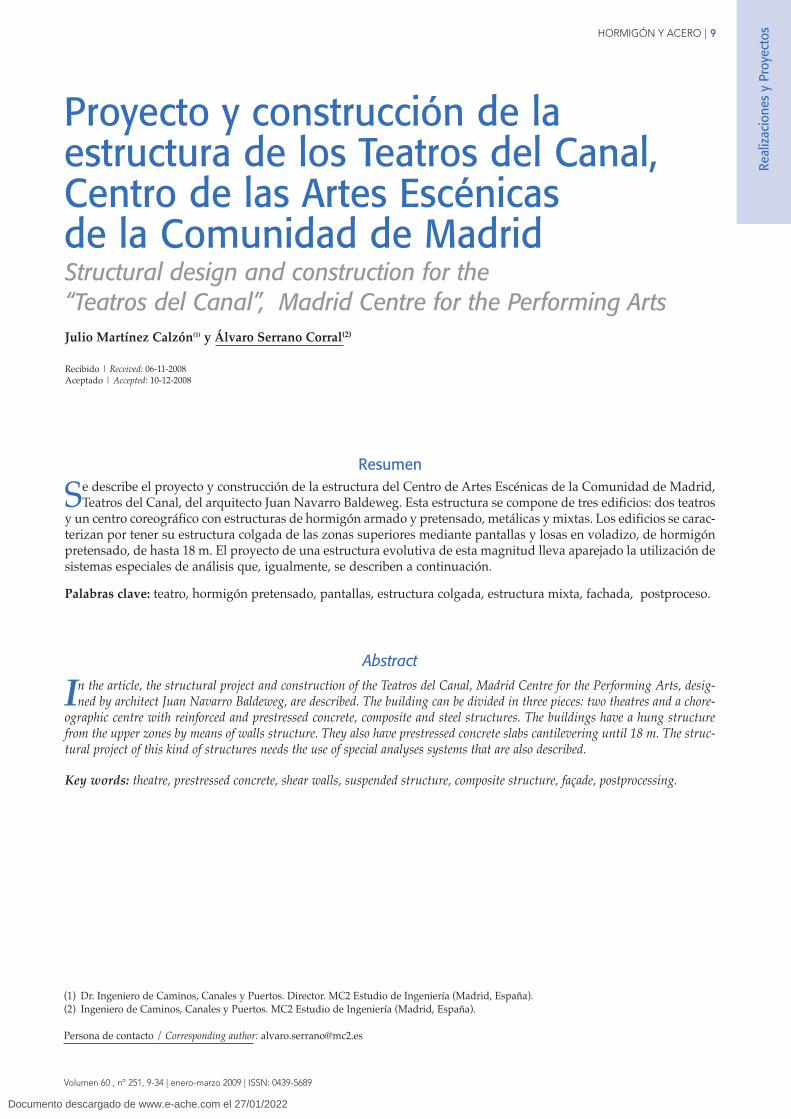
The Choreographic Centre has very different functionalrequirements from the theatres and this is reflected by itsstructural type which, in this case, is in the form of columns,frames and slabs formed in reinforced concrete in the lowerfloors below ground level and in steel or composite materialin the upper floors (Fig. 22).
The structure is apparently more conventional but is madecomplicated by the geometric arrangements of this part ofthe building, with numerous changes in level, double andtriple heights levels, different flooring thicknesses and thelarge amount of installations within the same.
The horizontal forces are taken by the screen walls and liftcores, and the floor slabs are considered as rigid diaphragms.
The classrooms and dance rooms are of particular note inthis building and require wide open spaces of double andtriple height (6.40 m y 10.40 m respectively), and greatamplitude (15 m x 30 m without intermediate supports).
Real
izac
ione
s y
Proy
ecto
s
Figura 19. Interior de la caja escénica del Teatro Configurable. Estructuras mixtas.Figure 19. Composite structures inside the Configurable Theatre stage house.
Figura 20. Entramados mixtos de la zona alta del Teatro Configurable.Figure 20. Composite frames in the upper zone of the Configurable Theatre.
Documento descargado de www.e-ache.com el 27/01/2022
HORMIGÓN Y ACERO | 21
J. Martínez Calzón y Á. SerranoVolumen 60 , nº 251, 9-34 | enero-marzo 2009 | ISSN: 0439-5689
Structural design and construction for the “Teatros del Canal”…
These rooms are structurally solved with the previouslyindicated structural type (Fig. 23).
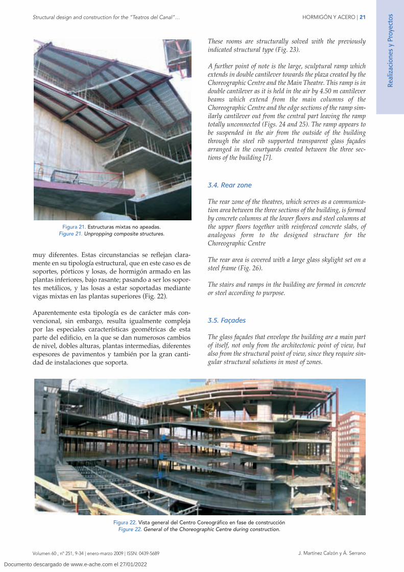
A further point of note is the large, sculptural ramp whichextends in double cantilever towards the plaza created by theChoreographic Centre and the Main Theatre. This ramp is indouble cantilever as it is held in the air by 4.50 m cantileverbeams which extend from the main columns of theChoreographic Centre and the edge sections of the ramp sim-ilarly cantilever out from the central part leaving the ramptotally unconnected (Figs. 24 and 25). The ramp appears tobe suspended in the air from the outside of the buildingthrough the steel rib supported transparent glass façadesarranged in the courtyards created between the three sec-tions of the building [7].
3.4. Rear zone
The rear zone of the theatres, which serves as a communica-tion area between the three sections of the building, is formedby concrete columns at the lower floors and steel columns atthe upper floors together with reinforced concrete slabs, ofanalogous form to the designed structure for theChoreographic Centre
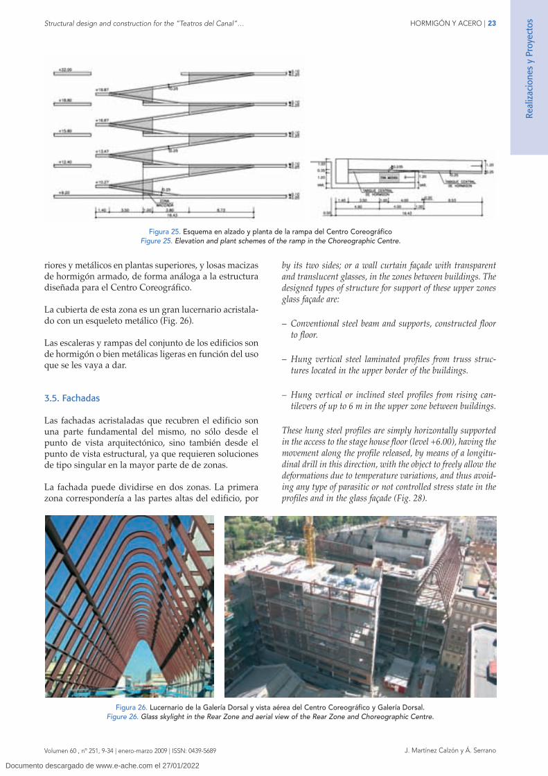
The rear area is covered with a large glass skylight set on asteel frame (Fig. 26).
The stairs and ramps in the building are formed in concreteor steel according to purpose.
3.5. Façades
The glass façades that envelope the building are a main partof itself, not only from the architectonic point of view, butalso from the structural point of view, since they require sin-gular structural solutions in most of zones.
muy diferentes. Estas circunstancias se reflejan clara-mente en su tipología estructural, que en este caso es desoportes, pórticos y losas, de hormigón armado en lasplantas inferiores, bajo rasante; pasando a ser los sopor-tes metálicos, y las losas a estar soportadas mediantevigas mixtas en las plantas superiores (Fig. 22).
Aparentemente esta tipología es de carácter más con-vencional, sin embargo, resulta igualmente complejapor las especiales características geométricas de estaparte del edificio, en la que se dan numerosos cambiosde nivel, dobles alturas, plantas intermedias, diferentesespesores de pavimentos y también por la gran canti-dad de instalaciones que soporta.
Real
izac
ione
s y
Proy
ecto
s
Figura 21. Estructuras mixtas no apeadas.Figure 21. Unpropping composite structures.
Figura 22. Vista general del Centro Coreográfico en fase de construcciónFigure 22. General of the Choreographic Centre during construction.
Documento descargado de www.e-ache.com el 27/01/2022

22 | HORMIGÓN Y ACERO
Volumen 60 , nº 251, 9-34 | enero-marzo 2009 | ISSN: 0439-5689 J. Martínez Calzón y Á. Serrano
Proyecto y construcción de la estructura de los Teatros del Canal,…
Las acciones horizontales existentes, en este caso única-mente de viento, se recogen mediante pantallas y núcle-os de ascensores, considerando los forjados como dia-fragmas rígidos.
Destacan en este edificio las aulas y salas dedicadas a ladanza que se caracterizan por ser espacios de doble ytriple altura (6.40 m y 10.40 m respectivamente), y granamplitud (15 m x 30 m sin soportes intermedios). Estassalas se han resuelto estructuralmente con la tipologíaindicada anteriormente (Fig. 23).
Otro elemento singular, no sólo en cuanto a su diseñoestructural, sino también por su intención formal, es lagran rampa de carácter escultórico que comunica lasdiferentes plantas del Centro Coreográfico, por el late-ral exterior del edificio. Esta rampa se compone de unalosa de hormigón armado de 25 cm de canto, que se sos-tiene desde cada piso, mediante vigas en ménsula de4.50 m de vuelo, y desde las cuales la rampa, a su vez,vuela longitudinalmente hasta alcanzar una longitudtotal máxima de 16.50 m, de manera que la percepciónvisual exterior es que la rampa esta suspendida flotan-do en el aire. Los tramos adyacentes de la rampa estánunidos mediante tabiques verticales y triangulares dehormigón armado que permiten alcanzar en la losa laimportante esbeltez mencionada (Figs. 24 y 25).
Esta rampa puede verse perfectamente desde el exteriordel edificio, a través de la fachada acristalada semi-transparente que se ha dispuesto en la plaza que se creaentre el Teatro Principal y el Centro Coreográfico [7].
3.4. Zona Dorsal
La zona dorsal de los teatros, que sirve de comunica-ción entre las tres piezas del edificio se resuelve con unaestructura de soportes de hormigón en las plantas infe-
The glass façade can be divided in two zones. The first zonecorresponds to the upper parts of the building, over the levelof access to the houses (fig. 27). In this zone, the façade iscavity-wall façade with opaque red, black or silver colourglasses, according to the building that envelopes, and visible
Real
izac
ione
s y
Proy
ecto
s
Figura 23. Salas de danza de doble y triple altura del Centro CoreográficoFigure 23. Double and triple height dance room in the Choreographic Centre.
Figura 24. Vista exterior e interior de la rampa del Centro Coreográfico.
Figure 24. Outer and inner view of the ramp in the Choreographic Centre.
Documento descargado de www.e-ache.com el 27/01/2022
HORMIGÓN Y ACERO | 23
J. Martínez Calzón y Á. SerranoVolumen 60 , nº 251, 9-34 | enero-marzo 2009 | ISSN: 0439-5689
Structural design and construction for the “Teatros del Canal”…
by its two sides; or a wall curtain façade with transparentand translucent glasses, in the zones between buildings. Thedesigned types of structure for support of these upper zonesglass façade are:
– Conventional steel beam and supports, constructed floorto floor.
– Hung vertical steel laminated profiles from truss struc-tures located in the upper border of the buildings.
– Hung vertical or inclined steel profiles from rising can-tilevers of up to 6 m in the upper zone between buildings.
These hung steel profiles are simply horizontally supportedin the access to the stage house floor (level +6.00), having themovement along the profile released, by means of a longitu-dinal drill in this direction, with the object to freely allow thedeformations due to temperature variations, and thus avoid-ing any type of parasitic or not controlled stress state in theprofiles and in the glass façade (Fig. 28).
riores y metálicos en plantas superiores, y losas macizasde hormigón armado, de forma análoga a la estructuradiseñada para el Centro Coreográfico.
La cubierta de esta zona es un gran lucernario acristala-do con un esqueleto metálico (Fig. 26).
Las escaleras y rampas del conjunto de los edificios sonde hormigón o bien metálicas ligeras en función del usoque se les vaya a dar.
3.5. Fachadas
Las fachadas acristaladas que recubren el edificio sonuna parte fundamental del mismo, no sólo desde elpunto de vista arquitectónico, sino también desde elpunto de vista estructural, ya que requieren solucionesde tipo singular en la mayor parte de de zonas.
La fachada puede dividirse en dos zonas. La primerazona correspondería a las partes altas del edificio, por
Real
izac
ione
s y
Proy
ecto
s
Figura 25. Esquema en alzado y planta de la rampa del Centro CoreográficoFigure 25. Elevation and plant schemes of the ramp in the Choreographic Centre.
Figura 26. Lucernario de la Galería Dorsal y vista aérea del Centro Coreográfico y Galería Dorsal.Figure 26. Glass skylight in the Rear Zone and aerial view of the Rear Zone and Choreographic Centre.
Documento descargado de www.e-ache.com el 27/01/2022

24 | HORMIGÓN Y ACERO
Volumen 60 , nº 251, 9-34 | enero-marzo 2009 | ISSN: 0439-5689 J. Martínez Calzón y Á. Serrano
Proyecto y construcción de la estructura de los Teatros del Canal,…
encima de la cota de entrada de las salas (Fig. 27). Enesta zona, la fachada es de tipo ventilada con vidriosopacos de color negro, rojo o plata, según los edificiosque cierra, y visible por sus dos lados; o bien de tipomuro cortina con vidrios transparentes o translúcidos,en las zonas entre cuerpos. Los tipos de estructura dise-ñados para soporte de esta fachada acristalada de laparte superior son de tres tipos:
– Soportes y vigas metálicos de tipo convencional,construidos planta a planta.
– Perfiles verticales metálicos colgados desde estructurasen celosía situadas en el borde superior de los edificios,que salvan luces importantes en voladizo y en cuelgue.
These hung steel profiles must respect the very strict defor-mative conditions that require the façades of glass elements,being in the case of the inclined profiles especially important,since the selfweight of the façade determines an appreciablebending in these profiles.
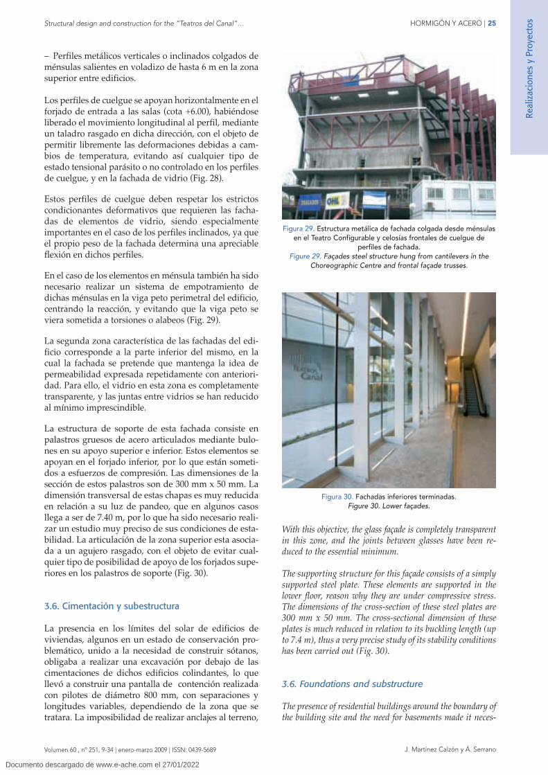
In the case of the cantilever structural elements, it has alsobeen necessary to make a system of rigidly fixing in thespandrel beam of the building, centring the reaction, andavoiding that the spandrel beam was put under torsion orwarping (Fig. 29).
The second zone of the building façades corresponds to itslower part, in which the façade must maintain the repeated-ly previously expressed conceptual idea of permeability.
Real
izac
ione
s y
Proy
ecto
s
Figura 27. Estructura metálica de las fachadas superiores colgadas.Figure 27. Upper façades steel structure.
Figura 28. Estructura metálica de fachada colgada desde ménsulas en el espacio entre el Centro Coreográfico y el Teatro Principal.Figure 28. Upper façades steel structure hung from cantilevers between the Choreographic Centre and the Main Theatre.
Documento descargado de www.e-ache.com el 27/01/2022
HORMIGÓN Y ACERO | 25
J. Martínez Calzón y Á. SerranoVolumen 60 , nº 251, 9-34 | enero-marzo 2009 | ISSN: 0439-5689
Structural design and construction for the “Teatros del Canal”…
With this objective, the glass façade is completely transparentin this zone, and the joints between glasses have been re-duced to the essential minimum.
The supporting structure for this façade consists of a simplysupported steel plate. These elements are supported in thelower floor, reason why they are under compressive stress.The dimensions of the cross-section of these steel plates are300 mm x 50 mm. The cross-sectional dimension of theseplates is much reduced in relation to its buckling length (upto 7.4 m), thus a very precise study of its stability conditionshas been carried out (Fig. 30).
3.6. Foundations and substructure
The presence of residential buildings around the boundary ofthe building site and the need for basements made it neces-
– Perfiles metálicos verticales o inclinados colgados deménsulas salientes en voladizo de hasta 6 m en la zonasuperior entre edificios.
Los perfiles de cuelgue se apoyan horizontalmente en elforjado de entrada a las salas (cota +6.00), habiéndoseliberado el movimiento longitudinal al perfil, medianteun taladro rasgado en dicha dirección, con el objeto depermitir libremente las deformaciones debidas a cam-bios de temperatura, evitando así cualquier tipo deestado tensional parásito o no controlado en los perfilesde cuelgue, y en la fachada de vidrio (Fig. 28).
Estos perfiles de cuelgue deben respetar los estrictoscondicionantes deformativos que requieren las facha-das de elementos de vidrio, siendo especialmenteimportantes en el caso de los perfiles inclinados, ya queel propio peso de la fachada determina una apreciableflexión en dichos perfiles.
En el caso de los elementos en ménsula también ha sidonecesario realizar un sistema de empotramiento dedichas ménsulas en la viga peto perimetral del edificio,centrando la reacción, y evitando que la viga peto seviera sometida a torsiones o alabeos (Fig. 29).
La segunda zona característica de las fachadas del edi-ficio corresponde a la parte inferior del mismo, en lacual la fachada se pretende que mantenga la idea depermeabilidad expresada repetidamente con anteriori-dad. Para ello, el vidrio en esta zona es completamentetransparente, y las juntas entre vidrios se han reducidoal mínimo imprescindible.
La estructura de soporte de esta fachada consiste enpalastros gruesos de acero articulados mediante bulo-nes en su apoyo superior e inferior. Estos elementos seapoyan en el forjado inferior, por lo que están someti-dos a esfuerzos de compresión. Las dimensiones de lasección de estos palastros son de 300 mm x 50 mm. Ladimensión transversal de estas chapas es muy reducidaen relación a su luz de pandeo, que en algunos casosllega a ser de 7.40 m, por lo que ha sido necesario reali-zar un estudio muy preciso de sus condiciones de esta-bilidad. La articulación de la zona superior esta asocia-da a un agujero rasgado, con el objeto de evitar cual-quier tipo de posibilidad de apoyo de los forjados supe-riores en los palastros de soporte (Fig. 30).
3.6. Cimentación y subestructura
La presencia en los límites del solar de edificios deviviendas, algunos en un estado de conservación pro-blemático, unido a la necesidad de construir sótanos,obligaba a realizar una excavación por debajo de lascimentaciones de dichos edificios colindantes, lo quellevó a construir una pantalla de contención realizadacon pilotes de diámetro 800 mm, con separaciones ylongitudes variables, dependiendo de la zona que setratara. La imposibilidad de realizar anclajes al terreno,
Real
izac
ione
s y
Proy
ecto
s
Figura 29. Estructura metálica de fachada colgada desde ménsulasen el Teatro Configurable y celosías frontales de cuelgue de
perfiles de fachada.Figure 29. Façades steel structure hung from cantilevers in the
Choreographic Centre and frontal façade trusses.
Figura 30. Fachadas inferiores terminadas.Figure 30. Lower façades.
Documento descargado de www.e-ache.com el 27/01/2022

26 | HORMIGÓN Y ACERO
Volumen 60 , nº 251, 9-34 | enero-marzo 2009 | ISSN: 0439-5689 J. Martínez Calzón y Á. Serrano
Proyecto y construcción de la estructura de los Teatros del Canal,…
llevó a la necesidad de ejecutar la excavación con lapantalla de pilotes apoyada en una berma provisional,que se retiró al construir el primer forjado del edificio(Fig. 31).
La cimentación es de tipo superficial, consistente engrandes losas de hormigón, de formas complejas, en lasque se apoyan las pantallas verticales; y en zapatas paralos pilares y pantallas exentas menores. El canto dedichas losas es de 1.30 m para el Teatro Principal y de1.30 ó 1.60, según zonas, en el Teatro Configurable (Fi-gura 32). La cota de cimentación varía según zonas, lamás profunda a la cota –6.50, en las zonas dorsales, dondese aceptaban tensiones medias de hasta 0.45 N/mm2 y lamás superficial, en la cota –3.00, donde la tensión admi-sible considerada es de 0.30 N/mm2.
4. ASPECTOS DE PROYECTO Y DEL CÁLCULOESTRUCTURAL
El planteamiento del proyecto de una estructura tan sin-gular como la de los teatros, exigió igualmente, una
sary to excavate below the foundations of the adjacent build-ings. This subsequently required the construction of retain-ing walls formed by 800 mm diameter piles with variablespacing and length according to area. The impossibility tomake anchorages to the terrain, took to the necessity to exe-cute the excavation with the retaining wall of piles support-ed with a provisional berm that was retired when the firstfloor of building was constructed (Fig. 31).
The foundations to the vertical walls are formed in large con-crete slabs of complex shape, while the smaller walls andcolumns are set on footings. The thicknesses of the founda-tions vary from 1.30 m for the Main Theatre and 1.30 or1.60 m, according to the area, in the Configurable Theatre.The depth of the foundations also vary according to areawith the deepest being set at –6.50, in the rear areas, andwhich withstand average stresses of up 0.45 N/mm2 and themore superficial being set at a level of –3.00, where theadmissible stress considered is 0.30 N/mm2.
4. DESING ASPECTS AND STRUCTURAL CALCULATION
The design arrangement of such a unique structure requiredan equally special methodology. The complex geometricaland architectural arrangement, together with the evolution-ary nature of the structure, the functional requirements andthe complex structural interactions between the elements,made it impossible to use the majority of work and calcula-tion methods employed in more conventional buildings [5].
The total dimension of the building, along with the adoptedstructural type, strongly interlaced and monolithic, recom-mended the positioning of expansion joints that were setbetween each part of the building to minimize the effects oftemperature and shrinkage, very conditioning in the case ofhaving made an integral structural design.
The previous circumstance permitted separately representthe structure of each one of the theatres, by means of indivi-dual global models of finite elements which accurately repre-
Real
izac
ione
s y
Proy
ecto
s
Figura 31. Contención perimetral del solar.Figure 31. Retaining wall.
Figura 32. Hormigonado de la losa de cimentación del Teatro Configurable.Figure 32. Configurable Theatre foundation concreting.
Documento descargado de www.e-ache.com el 27/01/2022

HORMIGÓN Y ACERO | 27
J. Martínez Calzón y Á. SerranoVolumen 60 , nº 251, 9-34 | enero-marzo 2009 | ISSN: 0439-5689
Structural design and construction for the “Teatros del Canal”…
sented the walls, slabs, columns, beams and steel trussworkof each building. This then allowed the direct application ofdifferent loading hypotheses and had the additional advan-tage that the model could easily be separated into sections toenable a study of the construction process. The said modelincluded the foundations in order to consider the interactionof the structure with the soil (Fig. 33).
The great surface of floors and walls to dimension, 19.000 m2
in the Main Theatre and 15.000 m2 in the ConfigurableTheatre, gave finite elements models of great size: 26.200 ele-ments for the Main Theatre model and 22.100 for theConfigurable Theatre. This circumstance, together with tothe intense interaction of internal forces in each point of thestructure, and the necessity of optimization of thicknessesand reinforcement, in a reasonable time, determined thenecessity of using an automatic data postprocess, and aresults control system by means of simplified models, thatwill allow to verify the goodness of the obtained computerresults.
From the results of the stresses on the elements the ULS andSLS envelope of the structures was made. On the basis ofthis envelope, automatic numerical and graphic postprocess-ing in the finite elements code ANSYS was made in order todirectly obtain the amount of reinforcement required in theslabs and walls, considering the interaction between bendingand torque stresses and axial and shear stresses, accordingthe Eurocode rules. These internal forces were automaticallycompared with axial–bending interaction diagrams, tabulat-ed for different quantities of reinforcement in predefined pat-terns. The results of reinforcement patterns were also auto-matically represented in graphs of slabs and walls (Fig. 34).
The more conventional columns and beams were dimen-sioned in the same way. In certain special areas of the struc-ture, such as the main cantilever slabs in the theatre, moredetailed local models were made to verify the reliability of theresults of the general model and proved highly satisfactory.
metodología también singular. La especial configura-ción geométrica y arquitectónica de los edificios, unidaal carácter evolutivo de la estructura, las servidumbresfuncionales que se le imponían, las complejas interaccio-nes estructurales entre elementos tridimensionales y lanecesidad de monolitismo entre losas y pantallas, inva-lidaban una buena parte de los métodos de trabajo y decálculo aplicados en edificios más convencionales [5].
La dimensión total del edificio, junto con la tipologíaadoptada, fuertemente entrelazada y monolítica, reco-mendó la colocación de juntas entre los teatros, y entreel Teatro Principal y el Centro Coreográfico, con objetode reducir los efectos de las acciones térmicas e higro-métricas, muy condicionantes en el caso de haber reali-zado un diseño estructural integral.
La circunstancia anterior se aprovechó para representarla estructura de cada uno de los teatros por separado,mediante sendos modelos globales de elementos finitosque representaban con precisión las pantallas, losas,pilares, vigas y entramados metálicos que componíancada edificio. Esto permitía aplicar directamente las dis-tintas hipótesis de carga adoptadas, y además, tenía laventaja de que cada modelo podía segregarse fácilmen-te en partes para el estudio secuencial del proceso cons-tructivo. En dicho modelo se incluyó la cimentaciónpara tener en cuenta la interacción de la estructura conel terreno (Fig. 33).
La amplia superficie de forjados y pantallas a dimensio-nar, 19.000 m2 en el Teatro Principal y 15.000 m2 en elTeatro Configurable, dio lugar a grandes modelos de ele-mentos finitos: 26.200 elementos en el Teatro Principal y22.100 en el Teatro Configurable. Esta circunstancia,unida a la intensa interacción de esfuerzos en cada puntode la estructura, y a la necesidad de optimización deespesores y armaduras, en un plazo de tiempo razonable,determinó la necesidad de utilizar un postproceso de
Real
izac
ione
s y
Proy
ecto
s
Figura 33. Modelos de elementos finitos del Teatro configurable (izq.) y Principal (dcha.).Figure 33. Configurable Theatre (left) and Main Theatre (right) finite elements models.
Documento descargado de www.e-ache.com el 27/01/2022

28 | HORMIGÓN Y ACERO
Volumen 60 , nº 251, 9-34 | enero-marzo 2009 | ISSN: 0439-5689 J. Martínez Calzón y Á. Serrano
Proyecto y construcción de la estructura de los Teatros del Canal,…
datos de tipo automático, y un sistema de control deresultados mediante modelos simplificados, que permiti-rá comprobar la bondad de los resultados informáticosobtenidos.
Con el objetivo anterior, a partir de los resultados deesfuerzos en los elementos del modelo se realizó laenvolvente de cálculo (valores mayorados) y de servi-cio (valores característicos) de las estructuras. Con estasenvolventes se programó en el código de elementosfinitos ANSYS un postproceso automático, tanto numé-rico como gráfico, que permitía obtener directamentelas armaduras necesarias en las losas y pantallas, te-niendo en cuenta las interacciones entre esfuerzos deflexión y torsión, y de axil y rasante, de acuerdo con lasreglas de interacción de Wood y Armer, recogidas en elEurocódigo, para obtener parejas de esfuerzos de axil ymomento flector equivalente en las dos direcciones dearmado de la lámina. Estas parejas de esfuerzos se com-paraban automáticamente con los diagramas de inter-acción axil – flexión, tabulados para distintas cuantíasde armadura representadas en patrones predefinidosde armado. Los resultados de los patrones de armado serepresentaban, también automáticamente, en gráficosde las losas y las pantallas (Fig. 34).
De la misma forma se dimensionaron los pilares y vigasconvencionales. De ciertas zonas singulares de la estruc-tura, como pueden ser las principales losas en voladizode los teatros, se realizaron también modelos locales másdetallados, para comprobar el buen ajuste de los resulta-dos del modelo general, que resultó ser extraordinaria.
Las vigas, celosías y entramados mixtos de las zonasaltas de los teatros, de carácter evolutivo, se calcularonmediante modelos locales, cuyos resultados se contras-taron con los obtenidos en los modelos generales.
The composite beams, trusses and frameworks to the upperareas of the theatres, of evolutionary nature, were calculatedby individual local models and the results were comparedwith those obtained from the general models.
6. CONSTRUCTION PROCESS
In the case of the theatres and given the evolutionary natureof the structure and the presence of large cantilevers and sus-pended areas supported on a structure such as this, a completestudy of the main stages of the final construction process wascarried out in order to estimate the reactions of supports, realprecambers during construction and the expected movementsduring the removal of supports in order to gauge the range ofthe hydraulic jacks required for this operation
The Choreographic Centre construction process is quite con-ventional, floor to floor, with some hung zones, to constructlater. On the contrary, the construction process of the twotheatres is similar and is essentially based on the followingstages [6]:
– Construction of the foundations and the first structuralwalls and slabs by conventional methods.
– Elevation of the walling forming the stage house by climb-ing formwork up to roof level (Fig. 35).
– Construction with temporary steel supports of the sus-pended structure consisting of the cantilevered slabs andwalls, up to the point where they reached sufficientstrength capacity to be self-bearing.
– Controlled unpropping of the structure built to this point,by means of hydraulic jacks at the top of the temporarysteel supports.
Real
izac
ione
s y
Proy
ecto
s
Figura 34. Fundamentos del postproceso automático.Figure 34. Automatic postprocess basis.
Documento descargado de www.e-ache.com el 27/01/2022

HORMIGÓN Y ACERO | 29
J. Martínez Calzón y Á. SerranoVolumen 60 , nº 251, 9-34 | enero-marzo 2009 | ISSN: 0439-5689
Structural design and construction for the “Teatros del Canal”…
– Forming of the remainder of the walls and slabs over theexisting structure.
– Closing of the roof covers by steel and composite struc-tures.
– Construction of the glass façade structure (Fig. 36).
One of the most crucial parts of the construction process wasthe removal of the temporary supports in the theatres. Thisprocess was carried out with seven 6500 kN capacityhydraulic jacks in the case of the Main Theatre and four sim-ilar jacks in the Configurable Theatre.
This operation was highly complex due to the high degree ofnot statically determination of the structure on unpropping,the operation of any of the jacks seriously affected the loadsacting on the others. A staged unpropping procedure wasestablished for these operations with simultaneous controlover loads and movements, based on the results obtained inthe evolutionary analyses (Figs. 37 y 38).
One of the fundamental problems consisted of determining,with a sufficient precision, the real load supported by everytemporary support, to recover it by means of hydraulic jacks.Although this load had been considered in the previousanalyses, if its real value were not determined with certainexactitude, it was in danger to overload the hydraulic jacksand to carry the structure to load states for which it was notdesigned. For this determination a procedure was designed.The operation was controlled by means of a micrometer that
6. PROCESO CONSTRUCTIVO
En el caso de los teatros, y dado el carácter evolutivo dela estructura, y la presencia de grandes voladizos y dezonas colgadas, que son soportadas en parte por laestructura que está sobre ellas, se realizó un estudio com-pleto de las principales fases del proceso constructivofinal, con objeto de estimar las reacciones en los apeosprovisionales, las contraflechas reales de construcción, yfinalmente los movimientos esperados en las fases dedesapeo, para el dimensionamiento de la carrera de losgatos hidráulicos necesarios para esta operación.
El proceso constructivo del Centro Coreográfico es detipo bastante convencional, planta a planta, con algunaszonas colgadas, a construir a posteriori. Por el contra-rio, la ejecución de los dos teatros es muy semejante yse basó fundamentalmente en las siguientes fases [6]:
– Construcción de la cimentación, y de las primeraspantallas estructurales y losas por procedimientos con-vencionales.
– Elevación mediante encofrados trepantes, hasta lacota de cubierta de las pantallas que conforman lacaja escénica (Fig. 35).
– Construcción mediante importantes apeos provisiona-les metálicos, de la estructura colgada consistente enlosas voladas y pantallas, hasta la cota en la que estasúltimas, en conjunto presentan una capacidad re-sistente suficiente para ser autoportantes.
Real
izac
ione
s y
Proy
ecto
s
Figura 35. Estructura de los teatros en fase de construcciónFigure 35. Theatres structure under construction.
Documento descargado de www.e-ache.com el 27/01/2022

30 | HORMIGÓN Y ACERO
Volumen 60 , nº 251, 9-34 | enero-marzo 2009 | ISSN: 0439-5689 J. Martínez Calzón y Á. Serrano
Proyecto y construcción de la estructura de los Teatros del Canal,…
– Desapeo controlado de la estructura construida hastaese momento, mediante gatos dispuestos en la coro-nación de los apeos metálicos provisionales.
– Ejecución del resto de pantallas y losas elevándoseapoyadas sobre la estructura existente.
– Cierre de las cubiertas mediante estructuras metáli-cas y mixtas autoportantes.
– Construcción de la estructura de las fachadas acrista-ladas (Fig. 36).
El principal punto singular del proceso constructivo delos teatros, fue el desapeo de su estructura parcial infe-rior, realizada mediante el empleo de 7 gatos hidráuli-cos de 6500 kN de capacidad máxima en el caso delTeatro Principal, y de 4 unidades similares para elTeatro Configurable.
Esta operación resulta de gran importancia ya que, debi-do a la gran hiperestaticidad de la estructura a desapear,la actuación en uno cualquiera de los gatos, modifica deforma importante las cargas actuantes sobre el resto. Paraestas maniobras se diseñó un procedimiento especial dedesapeo por fases, con control simultáneo de cargas ymovimientos, a partir de los valores obtenidos en losanálisis evolutivos (Figs. 37 y 38).
Uno de los problemas fundamentales consistía en deter-minar, con una precisión suficiente la carga real quesoportaba cada apeo, para recuperarla mediante gatos.Pese a que dicha carga se había estimado en los análisisprevios, si no se determinaba su valor real con ciertaexactitud, se corría el peligro de sobrecargar los gatos ysometer a la estructura a estados de carga para los que noestaba diseñada. Para esta determinación se diseñó unprocedimiento que controlaba mediante un micrómetrolos movimientos que se producían entre el apeo y la losaal ir cargando los gatos, registrando los valores en ungráfico de forma que, en el momento que se producía latotal transmisión de carga, la variación de rigidez del sis-tema apeo–gato–estructura provocaba un cambio de
registered the movements that took place between the tempo-rary support and the slab when the hydraulic jacks were putin load, registering the values in a graph so that, at themoment that the total transmission of load happened, thesystem support-jack-structure stiffness variation caused aslope change in the registered line, obtaining thus by inter-section of the two straight lines a very approximated valueof the existing load in temporary support (Fig. 39).
The operation was highly successful and in spite of the factthat this is a highly complex and not statically determinatedconcrete structure, the operations showed excellent corre-spondence with the expected loads and movements in thecase of the Main Theatre and a somewhat less precise butalways favourable correspondence in the case of theConfigurable Theatre (Fig. 40).
The study of the construction process, considering the timeof construction of each part of the structure and its creep,similarly provided the real movements in the cantilevers andallowed the definition of the necessary precambers.
Real
izac
ione
s y
Proy
ecto
s
Figura 36. Construcción de la estructura de fachadas.Figure 36. Façade structure construction.
Figura 37. Esquema de fases de la construcción del Teatro Principal: Estructura parcial apeada (izq.), desapeo (cent.) y finalización de la ejecución (dcha.)
Figure 37. Main Theatre construction phases scheme.
Documento descargado de www.e-ache.com el 27/01/2022

HORMIGÓN Y ACERO | 31
J. Martínez Calzón y Á. SerranoVolumen 60 , nº 251, 9-34 | enero-marzo 2009 | ISSN: 0439-5689
Structural design and construction for the “Teatros del Canal”…
It is interesting to indicate at this point, that the construc-tion process initially prepared in the project was made with-out the aforementioned temporary supports, constructing incantilever, nevertheless, the general contractor preferred toplace these steel temporary supports to facilitate the con-struction and to locally reduce the terms of construction,decision that was, without doubt, absolutely positive.
Finally, some images of the building in its last phases ofconstruction and finished (Figs. 41 to 47) are shown. Thetheatres were inaugurated with their total stage equipmentthe 23rd of September, 2008.
7. CONCLUSION
The Teatros del Canal opens a new line of structural designin which there is no difference between the functional, thearchitectural and the structural form, using the whole build-ing as structure, and taking the advantage of all the spatialstructural resources in order to optimize the structure of thebuildings. This also requires a mutual understandingbetween the architect and the structural engineer in order toobtain the best final result.
pendiente en la línea registrada, obteniéndose así porintersección de las dos rectas un valor muy aproximadode la carga existente en el apeo (Fig. 39).
Las maniobras se realizaron con éxito y, pese a ser unaestructura de hormigón sumamente compleja e hiperes-tática, con un excelente ajuste con las cargas y movi-mientos esperados en el caso del Teatro Principal, yalgo menos precisa, pero del lado favorable en el casodel Teatro Configurable (Fig. 40).
Igualmente, del estudio del proceso constructivo, consi-derando el instante de construcción de cada parte de laestructura y su fluencia, se obtuvieron los movimientosreales en los voladizos, para definir las contraflechasnecesarias.
Resulta interesante indicar en este punto, que el proce-so constructivo previsto inicialmente en el proyecto serealizaba sin los apeos provisionales antedichos, avan-zando en voladizo, sin embargo, la constructora prefiriócolocar estos apeos metálicos para facilitar la construc-ción y reducir localmente los plazos de construcción,decisión que resulto, sin duda, del todo positiva.
Real
izac
ione
s y
Proy
ecto
s
Figura 38. Apeos del Teatro principal con los gatos de desapeo colocados.Figure 38. Hydraulic jacks on the temporary supports of the Main Theatre.
Figura 39. Mecanismo de determinación de la carga en apeos. Micrómetro para determinación de movimientos.Figure 39. Procedure to determine the load on the temporary supports. Micrometre.
Documento descargado de www.e-ache.com el 27/01/2022

32 | HORMIGÓN Y ACERO
Volumen 60 , nº 251, 9-34 | enero-marzo 2009 | ISSN: 0439-5689 J. Martínez Calzón y Á. Serrano
Proyecto y construcción de la estructura de los Teatros del Canal,…
Finalmente, se muestran a continuación algunas imáge-nes del edificio en sus últimas fases de construcción yterminado (Figs. 41 a 47). Los teatros se inauguraroncon su total maquinaria el 23 de septiembre de 2008.
7. CONCLUSIÓN
Los Teatros del Canal representan una nueva línea dediseño estructural en la cual no existen diferencias sus-tanciales entre la forma estructural, arquitectónica yfuncional, usando el edificio completo como estructura,y aprovechando al máximo los recursos que este pro-porciona, con el objeto de optimizar su esquema resis-tente. Esto requiere un entendimiento mutuo entre elarquitecto y el ingeniero estructural para conseguir unresultado final excelente.
El proyecto de la estructura para un edificio de estas ca-racterísticas especiales, requiere igualmente una metodo-logía de trabajo especial. La complejidad geométrica y
The design arrangement of such an unique structurerequires an equally special methodology. The complex geo-metrical and architectural arrangement, the evolutionary
Real
izac
ione
s y
Proy
ecto
s
Figura 40. Gráficos comparativos de cargas en apeos (arriba) y movimientos de la estructura (abajo) entre el modelo de cálculo (rojo) y la realidad (azul)
Figure 40. Graphics of comparing between the analysis model (red) to reality (blue) for load on temporary supports (up) and structure movements (down).
Figura 41. Colocación de vidrios de fachada.Figure 41. Façade glasses placing.
Figura 42. Vista frontal del edificio en sus últimas fases de construcción
Figure 42. Frontal view of the building in its final phase of construction.
Figura 43. Vista lateral del edificio.Figure 43. Lateral view.
Documento descargado de www.e-ache.com el 27/01/2022

HORMIGÓN Y ACERO | 33
J. Martínez Calzón y Á. SerranoVolumen 60 , nº 251, 9-34 | enero-marzo 2009 | ISSN: 0439-5689
Structural design and construction for the “Teatros del Canal”…
nature of the structure, the functional requirements and thecomplex structural interactions between the elements, madeit impossible to use the majority of calculation methodsemployed in conventional buildings; and requires the use ofFE methods along with a powerful automatic post-proces-sing.
arquitectónica, la naturaleza evolutiva de la estructura,los requerimientos funcionales y las complejas interac-ciones entre elementos estructurales, hace imposible eluso de la mayoría de los métodos de cálculo empleadosen edificios convencionales, y requiere el empleo demétodos de elementos finitos asociados a potentes siste-mas de postproceso automático.
Real
izac
ione
s y
Proy
ecto
s
Figura 44. Vista del edificio terminado.Figure 44. Finished building view.
Figura 45. Vista del edificio terminado.Figure 45. Finished building view.
Figura 46. Atrio interior cubierto por la fachada acristalada.Figure 46. Inner atrium covered by the glass façade.
Figura 47. Interior de las salas configurable (izq.) y principal (dcha.)Figure 47. Inner view of the Configurable Theatre house (left) and Main theatre house (right).
Documento descargado de www.e-ache.com el 27/01/2022

34 | HORMIGÓN Y ACERO
Volumen 60 , nº 251, 9-34 | enero-marzo 2009 | ISSN: 0439-5689 J. Martínez Calzón y Á. Serrano
Proyecto y construcción de la estructura de los Teatros del Canal,…
8. REFERENCIAS
[1] Hernández Ayuso, A., Serrano Corral, A., TaberaAtienza, A.: Teatro del Canal. Centro de Artes Escénicas dela Comunidad de Madrid. Revista de Obras Públicas. Año153. Nº 3.469. Septiembre 2006. pp. 61-71
[2] Navarro Baldeweg, J.: Centro para las Artes Escénicasde la Comunidad de Madrid. El Croquis. Nº 133. 2006. pp.134-153
[3] Martínez Calzón, J., Serrano Corral, A.: Nuevas líne-as de diseño estructural: Los Teatros del Canal en Madrid.Informes de la Construcción. Vol. 58. Nº 504. Octubre –Diciembre 2006. pp. 65-66
[4] Madrid Ramos, M., Tabera Atienza, A., ÁlvarezAndrés, J.J.: Centro de Artes Escénicas de la Comunidad deMadrid. Zuncho. Nº 16. Junio 2008. pp. 2-12
[5] Martínez Calzón, J., Serrano Corral, A.: Teatro delCanal. Centro de Artes Escénicas de la Comunidad deMadrid. III Congreso de Puentes y Estructuras deEdificación de ACHE. Zaragoza. Noviembre 2005.
[6] Tabera García, A., Madrid Ramos, M., TaberaAtienza, A.: Proceso Constructivo del Teatro del Canal.Centro de Artes Escénicas de la Comunidad de Madrid. IIICongreso de Puentes y Estructuras de Edificación deACHE. Zaragoza. Noviembre 2005.
[7] Gómez Navarro, M.: Proyecto del Teatro del Canal. IICongreso de Puentes y Estructuras de Edificación deACHE. Madrid. Noviembre 2002.
8. REFERENCES
[1] Hernández Ayuso, A., Serrano Corral, A., TaberaAtienza, A.: Teatro del Canal. Centro de Artes Escénicasde la Comunidad de Madrid. Revista de Obras Públicas.Año 153. Nº 3.469. September 2006. pp. 61-71.
[2] Navarro Baldeweg, J.: Centro para las Artes Escénicasde la Comunidad de Madrid. El Croquis. Nº 133. 2006.pp. 134-153.
[3] Martínez Calzón, J., Serrano Corral, A.: Nuevas líneasde diseño estructural: Los Teatros del Canal en Madrid.Informes de la Construcción. Vol. 58. Nº 504. October –December 2006. pp. 65-66.
[4] Madrid Ramos, M., Tabera Atienza, A., Álvarez Andrés,J.J.: Centro de Artes Escénicas de la Comunidad deMadrid. Zuncho. Nº 16. June 2008. pp. 2-12.
[5] Martínez Calzón, J., Serrano Corral, A.: Teatro del Ca-nal. Centro de Artes Escénicas de la Comunidad deMadrid. III Congreso de Puentes y Estructuras deEdificación de ACHE. Zaragoza. November 2005.
[6] Tabera García, A., Madrid Ramos, M., Tabera Atienza,A.: Proceso Constructivo del Teatro del Canal. Centrode Artes Escénicas de la Comunidad de Madrid. IIICongreso de Puentes y Estructuras de Edificación de ACHE.Zaragoza. November 2005.
[7] Gómez Navarro, M.: Proyecto del Teatro del Canal. IICongreso de Puentes y Estructuras de Edificación de ACHE.Madrid. November 2002.
Real
izac
ione
s y
Proy
ecto
s
FICHA TÉCNICA / DATA SHEET
� Propiedad / Owner and site management: Canal de Isabel II. Comunidad de Madrid.
� Proyecto de Arquitectura / Architect: Juan Navarro Baldeweg
� Proyecto de Estructura / Structure: MC2 Estudio de Ingeniería
� Proyecto de Instalaciones / Facilities: Argu Ingeniería y Servicios
� Ingeniería Acústica / Acoustics: García-BBM
� Constructora obra civil / Civil Works contractor: UTE Dragados – OHL
� Constructora equipamiento / Stage equipment contractor: UTE Dragados – OHL – TyssenKrupp Elevadores
� Asistencia Técnica / Technical assistance: UTE Seti – Euroconsult.
� Estructura Metálica / Steel structure: Martifer.
� Pretensado / Prestressing: Tecpresa.
Documento descargado de www.e-ache.com el 27/01/2022