Proximity Elevator Control Panel - kerisys.com · Proximity Elevator Control Panel ... an LC-200P...
22
Proximity Elevator Control Panel Unit 17 Park Farm Industrial Estate 01879-001 Rev. E Buntingford, Herts SG9 9AZ UK TEL: 0870 444 7234 FAX: 0870 444 7240 Web: http://www.kerisys.com E-mail: [email protected] Page 1 of 22 LC-202P/LC-208P Quick Start Guide Keri has modified its PXL-250P Tiger Controller and SB-293 Satellite Board to tailor a system for Proximity elevator control applications. The LC-202 Elevator Control Panel is made up of an LC-200P Tiger Elevator Controller Board and an SB-200 Elevator Satellite Board, together in a standard PXL-250 enclosure. The LC-208 Elevator Control Panel combines four LC-200 panels with four SB-200 boards in a rugged enclosure. The LC-202P provides two floor increments of elevator control at an economical price. Users can mount a single MS Series Proximity Reader inside an elevator cab and connect it to up to 12 LC-202Ps to control floor access for up to 24 floors. Used in conjunction with Doors32 software, this combination can be a very cost-effective elevator control solution. The LC-208P provides eight floors of elevator control in a small, integrated package. As with the LC-202P, a single MS Series Proximity Reader is mounted inside an elevator cab and then is connected to the LC-208P, providing controlled access for up to eight floors in a single enclosure. Any combination of LC-202Ps and LC-208Ps may be combined to control greater than eight floors. Check with local authorities when installing Elevator Control panels. Your elevator control application must meet all local and national safety codes. The Main or Lobby Floor cannot have access control applied – all people must be able to exit the elevator at all times on at least one common, ground-level access floor. 1.0 Important Considerations To ensure proper operation, the following considerations apply when using Doors32 software for elevator control. • Up to 24 floors can be controlled using any combination of LC-202Ps and LC-208Ps. • One reader in the elevator cab controls access for all floors. This reader is attached to all antenna inputs at all controllers in the elevator control system. This wiring scheme results in the one reader being responsible for access requests for all floors. Since the reader’s signal is being shared between multiple controller antenna inputs the reader's read range is reduced, possibly up to 25%. • User card presentation to the reader is critical. To ensure that all controllers have the opportunity to respond to a presented card, the card must be presented to the reader for a greater period of time – up to 2 seconds depending upon the length of the cable run and the number of controllers attached to the network. This allows all antenna inputs on all controllers the time necessary to respond to the card. If a card is not presented correctly, controllers that have not recognized the card will not allow access to the floors they control. • The reader's LED and beeper are used to indicate correct card presentation only, and does not indicate if all controllers have recognized the card or if access has been granted or denied (as done by a standard PXL-250 Tiger Controller).
Transcript of Proximity Elevator Control Panel - kerisys.com · Proximity Elevator Control Panel ... an LC-200P...

Proximity Elevator Control PanelLC
-202P/LC-208P
Quick Start G
uide
Keri has modified its PXL-250P Tiger Controller and SB-293 Satellite Board to tailor a system for Proximity elevator control applications. The LC-202 Elevator Control Panel is made up of an LC-200P Tiger Elevator Controller Board and an SB-200 Elevator Satellite Board, together in a standard PXL-250 enclosure. The LC-208 Elevator Control Panel combines four LC-200 panels with four SB-200 boards in a rugged enclosure.The LC-202P provides two floor increments of elevator control at an economical price. Users can mount a single MS Series Proximity Reader inside an elevator cab and connect it to up to 12 LC-202Ps to control floor access for up to 24 floors. Used in conjunction with Doors32 software, this combination can be a very cost-effective elevator control solution.
The LC-208P provides eight floors of elevator control in a small, integrated package. As with the LC-202P, a single MS Series Proximity Reader is mounted inside an elevator cab and then is connected to the LC-208P, providing controlled access for up to eight floors in a single enclosure.
Any combination of LC-202Ps and LC-208Ps may be combined to control greater than eight floors.
Check with local authorities when installing Elevator Control panels. Your elevator control application must meet all local and national safety codes. The Main or Lobby Floor cannot have access control applied – all people must be able to exit the elevator at all times on at least one common, ground-level access floor.
1.0 Important ConsiderationsTo ensure proper operation, the following considerations apply when using Doors32 software for elevator control.
• Up to 24 floors can be controlled using any combination of LC-202Ps and LC-208Ps.
• One reader in the elevator cab controls access for all floors. This reader is attached to all antenna inputs at all controllers in the elevator control system. This wiring scheme results in the one reader being responsible for access requests for all floors. Since the reader’s signal is being shared between multiple controller antenna inputs the reader's read range is reduced, possibly up to 25%.
• User card presentation to the reader is critical. To ensure that all controllers have the opportunity to respond to a presented card, the card must be presented to the reader for a greater period of time – up to 2 seconds depending upon the length of the cable run and the number of controllers attached to the network. This allows all antenna inputs on all controllers the time necessary to respond to the card. If a card is not presented correctly, controllers that have not recognized the card will not allow access to the floors they control.
• The reader's LED and beeper are used to indicate correct card presentation only, and does not indicate if all controllers have recognized the card or if access has been granted or denied (as done by a standard PXL-250 Tiger Controller).
Unit 17 Park Farm Industrial Estate 01879-001 Rev. EBuntingford, Herts SG9 9AZ UKTEL: 0870 444 7234 FAX: 0870 444 7240Web: http://www.kerisys.com E-mail: [email protected] Page 1 of 22

Proximity Elevator Control PanelQ
uick
Sta
rt G
uide
LC-2
02P/
LC-2
08P
2.0 Hardware and Software Operating RequirementsAll standard hardware and software requirements for Doors32 software apply (refer to the Doors32 Users Guide – P/N 01821-002). To support elevator control, the following additional software and firmware requirements must be met.
• The Doors32 software must be at revision 3.42 or greater.• The controller firmware must be at revision 6.3.42 or greater.
3.0 Specifications
3.1 Unit Dimensions• LC-200P Controller PCB with or without SB-200 Satellite Board
- 7.00 inches high by 6.00 inches wide by 1.75 inches deep, including wiring connectors- (178 mm by 152 mm by 45 mm)
• LC-200P Controller PCB with an LCD-1 Alpha/Numeric Display- 8.25 inches high by 6.00 inches wide by 1.75 inches deep, including wiring connectors- (209 mm by 152 mm by 45 mm)
• LC-202P Enclosure- 9.70 inches high by 8.20 inches wide by 2.60 inches deep- (246 mm by 208 mm by 66 mm)
• LC-208P Enclosure- 18.50 inches high by 15.25 inches wide by 4.00 inches deep- (470 mm by 387 mm by 101 mm)
3.2 Operating Temperature and Humidity Range• 0°F to 140°F (-18°C to 60°C)• 0% to 90% Relative Humidity, non-condensing
3.3 Power Requirements• 12 VDC @ 750 mA for the LC-202P panel• 12 VDC @ 3 A for the LC-208P panel
3.4 Current Draw• 500 mA maximum current draw for a Controller with all options installed (SB-200, LCD-1,
and Reader)• 120 mA maximum for a LC-200P Controller• 150 mA maximum for an SB-200 Satellite Board• refer to Table 1 for Reader current draw
Table 1: Current Draw by Reader Type
MS-3000 MS-4000 MS-5000
50 mA 50 mA 100 mA
Unit 17 Park Farm Industrial Estate 01879-001 Rev. EBuntingford, Herts SG9 9AZ UKTEL: 0870 444 7234 FAX: 0870 444 7240Web: http://www.kerisys.com E-mail: [email protected] Page 2 of 22

Proximity Elevator Control PanelLC
-202P/LC-208P
Quick Start G
uide
3.5 Controller Memory Retention• 5 year lithium battery backup to support controller RAM and real-time clock3.6 Floor Control Relay Contact Rating• 24 VDC @ 1 Amp
When connecting to elevator control systems and the floor selection buttons, please verify the elevator system voltages. Most elevator systems operate on DC or AC voltages higher than the 24 VDC @ 1 Amp rating at which Keri Systems’ elevator controllers are rated.
Keri Systems recommends establishing a system connection point at which the access control system and elevator control system connect, and to which both the access control company and the elevator company have access. This assists in making the connections between the systems and in allowing for independent system troubleshooting.
• If the system voltages are different (or if you wish to fully protect the access control system from transient voltage spikes), these connections should be made via isolation relays or relay control boards.
• If the system voltages are the same and both systems are fully protected, or if the system connections are made between dry relay contacts, you may only need to use a terminal strip for these connections.
Please consult your local building codes for proper installation requirements and check with local permit departments to verify compliance. Elevator systems have Life Safety requirements and may also require a connection to a fire control system.
3.7 Cable Requirements• RS-232 Serial Cable
- four conductor, shielded, stranded AWG 24 wire (Belden 9534 or a heavier gauge)- 50 foot maximum length (per RS-232 industry specification – greater lengths are not
recommended)• RS-485 Network Cable
- one twisted, shielded pair of conductors, stranded, AWG 24 wire (Belden 9501 or a heavier gauge)
- 4,000 foot total network length (per RS-485 industry specification – greater lengths are not recommended)
• Input Power- two conductor, stranded, AWG 18 wire (Belden 8461 or a heavier gauge)- 200 foot maximum length
NOTE: On long power cable runs, the cable resistance causes a drop in voltage at the end of the cable run. Be sure your power supply provides 12 VDC at the end of the cable run.
Unit 17 Park Farm Industrial Estate 01879-001 Rev. EBuntingford, Herts SG9 9AZ UKTEL: 0870 444 7234 FAX: 0870 444 7240Web: http://www.kerisys.com E-mail: [email protected] Page 3 of 22

Proximity Elevator Control PanelQ
uick
Sta
rt G
uide
LC-2
02P/
LC-2
08P
• Reader to Panel- six conductor, shielded, stranded AWG 24 wire (Belden 9536 or a heavier gauge)
• Output Connections- two conductor, stranded AWG 22 (Belden 9532 or a heavier gauge)
NOTE: The Floor Control Relay may require a heavier gauge of wire depending upon the current demands of the elevator panel and the length of the wiring run.
NOTE: If plenum cable is required, please reference the Belden equivalent to the cable listed above.
4.0 Controller InstallationSections 4.1 and 4.2 are quick lists of things to do and to not do when installing LC-202P and LC-208P panels.
4.1 Do• Plan ahead to meet power and telephone requirements for your system (1 phone line for the
host computer and one for each master LC-200P controller in each network).• Mount controllers in environmentally suitable areas – they require protection from weather
and from temperature/humidity extremes.• Mount the controller at least 3 feet away from the controller's power supply to prevent EMI
radiated from the power supply from affecting the controller.• Use the enclosure as a mounting template to mark drilling holes for permanent mounting.• Consider mounting requirements - central versus distributed.
- Central mounting places all controllers in one location, running lengths of cables out to each door to support readers, inputs and outputs.
- Distributed mounting places each controller near the door it supports running short lengths of cable out to each door, but running a long network communication cable.
• Note the locations of the knockouts in the enclosures and remove the appropriate knockout for the easiest cable routing into the controller.
• Route all controllers in a network in a single, continuous daisy-chain.• Route cables in accessible areas for ease of maintenance.• Connect all controllers to a quality earth ground.• Add transient suppression across electric devices attached to a controller output.• Verify the controller's supply voltage is 12 VDC – long power line runs cause a drop in
voltage at the end of the run.• Verify proper operation of the host computer's COM port.• Attach the reader to be used for card enrollment to the master controller (this reader can be
used for access control as well as enrollment, but during the enrollment process the door associated with the enrollment reader will not allow access until the enrollment process is complete).
Unit 17 Park Farm Industrial Estate 01879-001 Rev. EBuntingford, Herts SG9 9AZ UKTEL: 0870 444 7234 FAX: 0870 444 7240Web: http://www.kerisys.com E-mail: [email protected] Page 4 of 22

Proximity Elevator Control PanelLC
-202P/LC-208P
Quick Start G
uide
4.2 Do Not• Make modem phone line connections through PBX telephone switching systems - mostmodems are not compatible with PBX systems leading to disconnection problems with the modem.
• Locate a LC-200P controller near EMI sources - EMI sources can affect the performance of the controller.
• Locate a reader near EMI sources - EMI sources can affect the performance of the reader.• Use switching power supplies - they are EMI sources.• Route network and reader cables beside power cables - transients on the power cables may
be picked-up by network and reader cables.• Stretch or over-tension cables.• Route cables over sharp objects.• Let the cables get tangled.• Mix LC-200Ps with PXL-100s in the same network.• Connect earth ground to the network cable shield - the LC-200P automatically connects
earth ground to the shield at one point on the network to prevent ground loops.• Use gender changer plugs when making RS-232 serial communication connections (unless
you know it is a "straight-through" plug) - gender changers may have internal wiring changes that can disrupt communications.
Unit 17 Park Farm Industrial Estate 01879-001 Rev. EBuntingford, Herts SG9 9AZ UKTEL: 0870 444 7234 FAX: 0870 444 7240Web: http://www.kerisys.com E-mail: [email protected] Page 5 of 22

Proximity Elevator Control PanelQ
uick
Sta
rt G
uide
LC-2
02P/
LC-2
08P
5.0 Wiring ConnectionsBefore performing any wiring or connection operations, ensure that controller power is OFF. Serious damage to sensitive components on the controller may occur if wiring changes are made while controller power is on.
• Refer to Figure 1 below and Figure 2 on page 7 when reviewing the information throughout Section 5.2 beginning on page 9.
• Refer to Figure 3 on page 8 when reviewing the information throughout Section 5.3 beginning on page 14.
Figure 1: The LC-200P Elevator Controller
Unit 17 Park Farm Industrial Estate 01879-001 Rev. EBuntingford, Herts SG9 9AZ UKTEL: 0870 444 7234 FAX: 0870 444 7240Web: http://www.kerisys.com E-mail: [email protected] Page 6 of 22

Proximity Elevator Control PanelLC
-202P/LC-208P
Quick Start G
uide
Figure 2: The SB-200 Satellite Board
Unit 17 Park Farm Industrial Estate 01879-001 Rev. EBuntingford, Herts SG9 9AZ UKTEL: 0870 444 7234 FAX: 0870 444 7240Web: http://www.kerisys.com E-mail: [email protected] Page 7 of 22

Proximity Elevator Control PanelQ
uick
Sta
rt G
uide
LC-2
02P/
LC-2
08P
Figure 3: The LC-208P Elevator Control Panel
Unit 17 Park Farm Industrial Estate 01879-001 Rev. EBuntingford, Herts SG9 9AZ UKTEL: 0870 444 7234 FAX: 0870 444 7240Web: http://www.kerisys.com E-mail: [email protected] Page 8 of 22

Proximity Elevator Control PanelLC
-202P/LC-208P
Quick Start G
uide
5.1 Connecting Wires - Removing Terminal BlocksFollow the instructions in Figure 4 when connecting wires to the controller or when removing terminal blocks from the controller.Figure 4: Connecting Wires and Removing Terminal Blocks
5.2 LC-202P Wiring ConnectionsThe following connections are made to install the LS-202P Elevator Control panel (see Figure 3 on page 8).
• Floor Control Relay via TB-A• RS-485 Controller Network via TB-B (network out) and TB-C (network in)• Reader Daisy-Chain via TB-B (reader output) and TB-C (reader input)• Earth Ground and Power via TB-C
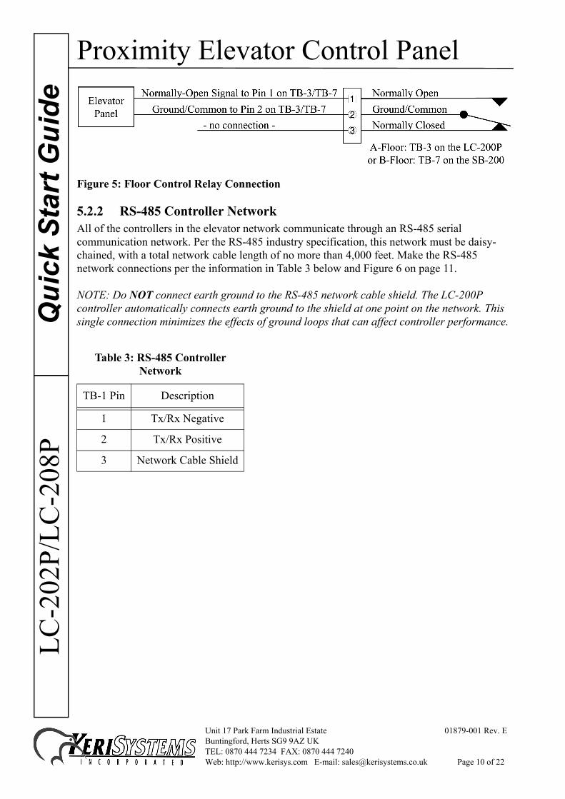
5.2.1 Floor Control RelayThe Floor Control Relay is connected to the floor controls at the elevator panel. If a controller has an SB-200 Satellite Board attached to control two floors, connect the lower floor to the A-Floor Control Relay and connect the higher floor to the B-Floor Control Relay. Make the floor control relay connections per the information in Table 2 below and Figure 5 on page 10.
Table 2: Floor Control Relay Connection
LC-200P TB-3 PinSB-200 TB-7 Pin Description
1 Normally-Open
2 Common
3 Normally-Closed
Unit 17 Park Farm Industrial Estate 01879-001 Rev. EBuntingford, Herts SG9 9AZ UKTEL: 0870 444 7234 FAX: 0870 444 7240Web: http://www.kerisys.com E-mail: [email protected] Page 9 of 22
Proximity Elevator Control PanelQ
uick
Sta
rt G
uide
LC-2
02P/
LC-2
08P
Figure 5: Floor Control Relay Connection
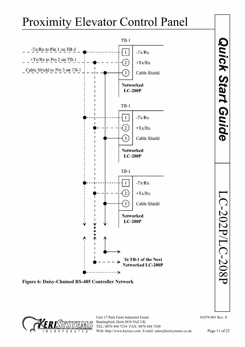
5.2.2 RS-485 Controller NetworkAll of the controllers in the elevator network communicate through an RS-485 serial communication network. Per the RS-485 industry specification, this network must be daisy-chained, with a total network cable length of no more than 4,000 feet. Make the RS-485 network connections per the information in Table 3 below and Figure 6 on page 11.
NOTE: Do NOT connect earth ground to the RS-485 network cable shield. The LC-200P controller automatically connects earth ground to the shield at one point on the network. This single connection minimizes the effects of ground loops that can affect controller performance.
Table 3: RS-485 Controller Network
TB-1 Pin Description
1 Tx/Rx Negative
2 Tx/Rx Positive
3 Network Cable Shield
Unit 17 Park Farm Industrial Estate 01879-001 Rev. EBuntingford, Herts SG9 9AZ UKTEL: 0870 444 7234 FAX: 0870 444 7240Web: http://www.kerisys.com E-mail: [email protected] Page 10 of 22
Proximity Elevator Control PanelLC
-202P/LC-208P
Quick Start G
uide
Figure 6: Daisy-Chained RS-485 Controller Network
Unit 17 Park Farm Industrial Estate 01879-001 Rev. EBuntingford, Herts SG9 9AZ UKTEL: 0870 444 7234 FAX: 0870 444 7240Web: http://www.kerisys.com E-mail: [email protected] Page 11 of 22

Proximity Elevator Control PanelQ
uick
Sta
rt G
uide
LC-2
02P/
LC-2
08P
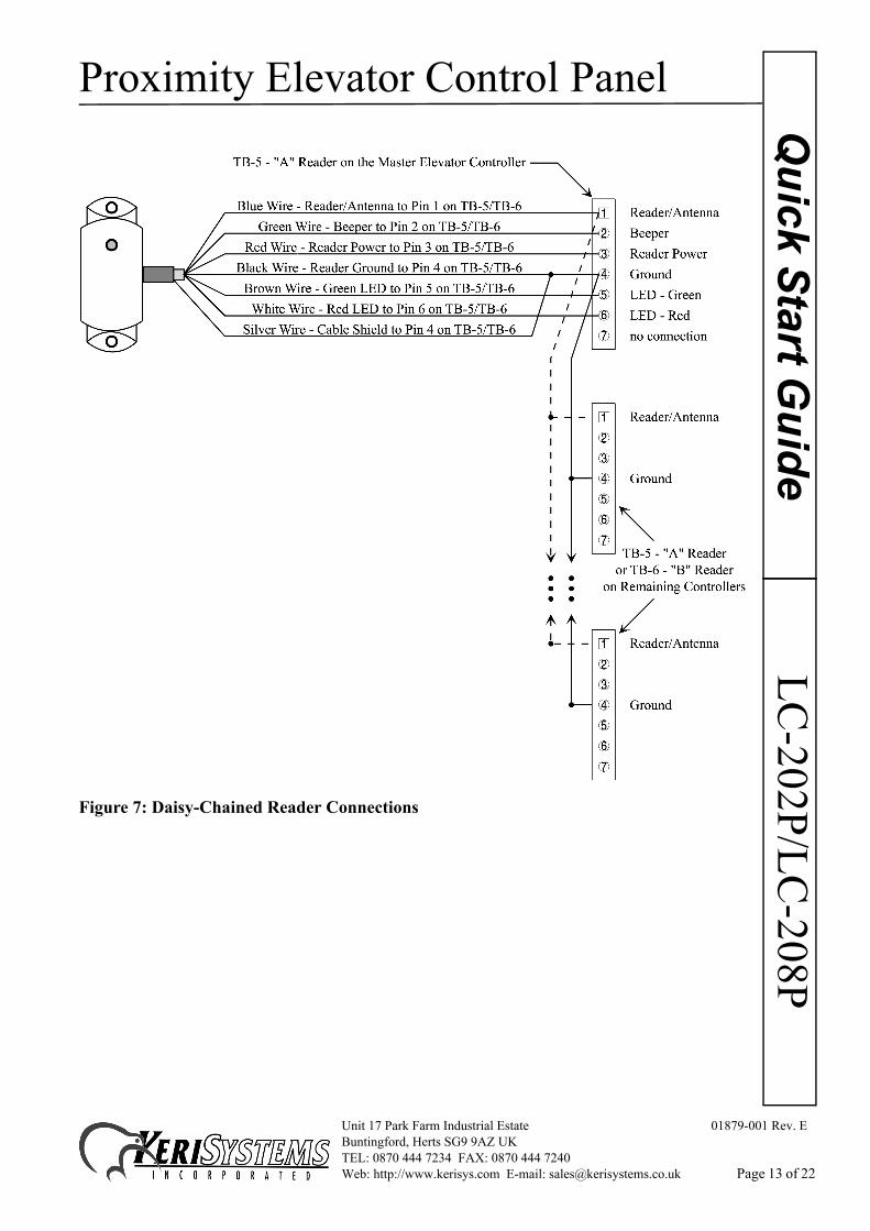
5.2.3 Reader Daisy-ChainOne Proximity reader is shared by all elevator control panels in an elevator control application. The main reader connections are made to a primary LC-202P elevator panel. All other reader connections to the remaining LC-202P panels are made per the following rules.
1. The reader antenna line must be daisy-chained to all other elevator panel antenna inputs – Pin 1 of TB-5 and TB-6 on the LC-202P panels.
2. The reader ground line must be daisy-chained to all other elevator panel antenna grounds to provide a standard ground reference for all panels – Pin 4 of TB-5 and TB-6 on the LC-202P panels.
3. The reader shield line must be connected to the A-floor controller antenna ground at the master elevator panel ONLY (Pin 4 of TB-5 on the master LC-202P panel).
4. The reader power line must be connected to the master elevator panel ONLY (Pin 3 of TB-5 on the master LC-202P panel).
Make the reader connections per the information in Table 4 below and Figure 7 on page 13.
Table 4: Daisy-Chained Reader Connections
TB-5/TB-6 Pin Description
1 Antenna
2 Beeper
3 Power
4 Ground
5 Green LED
6 Red LED
7 - no connection -
Unit 17 Park Farm Industrial Estate 01879-001 Rev. EBuntingford, Herts SG9 9AZ UKTEL: 0870 444 7234 FAX: 0870 444 7240Web: http://www.kerisys.com E-mail: [email protected] Page 12 of 22
Proximity Elevator Control PanelLC
-202P/LC-208P
Quick Start G
uide
Figure 7: Daisy-Chained Reader Connections
Unit 17 Park Farm Industrial Estate 01879-001 Rev. EBuntingford, Herts SG9 9AZ UKTEL: 0870 444 7234 FAX: 0870 444 7240Web: http://www.kerisys.com E-mail: [email protected] Page 13 of 22

Proximity Elevator Control PanelQ
uick
Sta
rt G
uide
LC-2
02P/
LC-2
08P
5.2.4 Earth Ground and PowerThe LC-202P panel requires 12 VDC power at 750 mA. You must make a quality earth ground connection to the controller prior to connecting the DC power lines. The earth ground provides protection for the controller and ensures the best possible operating conditions. Possible sources for earth ground are a ground rod, a cold water pipe, a steel building frame, the electrical system ground at the breaker/fuse box, or the telephone system ground. Make the earth ground and power connections per the information in Table 5 and Figure 8.
Figure 8: Earth Ground and Power Connections
5.3 LC-208 Wiring ConnectionsThe connections between the individual LC-200P/ SB-200 controllers in the LC-208 Elevator Control panel are already wired. All user connections are brought out to three terminal strips.
• one strip on the left side of the enclosure for all Floor Control Relay connections• one strip on the bottom-right of the enclosure for the controller power, the controller
network daisy-chain input, and the proximity reader daisy-chain input connections• one strip on the bottom-left of the enclosure for the controller network daisy-chain output
and the proximity reader daisy-chain output connections
Figure 9 on page 15 provides a diagram of these terminal strip connections.
Table 5: Earth Ground and Power Connections
TB-2 Pin Description
1 + 12 VDC Power Line
2 - 12 VDC Power Line
3 Earth Ground
Unit 17 Park Farm Industrial Estate 01879-001 Rev. EBuntingford, Herts SG9 9AZ UKTEL: 0870 444 7234 FAX: 0870 444 7240Web: http://www.kerisys.com E-mail: [email protected] Page 14 of 22

Proximity Elevator Control PanelLC
-202P/LC-208P
Quick Start G
uide
Figure 9: LC-208 Elevator Panel Wiring Connections
Unit 17 Park Farm Industrial Estate 01879-001 Rev. EBuntingford, Herts SG9 9AZ UKTEL: 0870 444 7234 FAX: 0870 444 7240Web: http://www.kerisys.com E-mail: [email protected] Page 15 of 22

Proximity Elevator Control PanelQ
uick
Sta
rt G
uide
LC-2
02P/
LC-2
08P
5.4 Wiring Multiple Panels TogetherUp to 24 floors can be controlled using a combination of LC-202Ps and LC-208Ps; the first eight floors must be controlled by an LC-208P. After that, any combination of LC-202Ps and LC-208Ps can be added to meet your floor requirements.
5.4.1 LC-208P/LC-202P CombinationPerform the following wiring instructions to accommodate an elevator application using an LC-208P and one or more LC-202P panels (9 to 16 floors).
1. Make a complete set of connections to the LC-208P panel. Refer to Section 5.3 on page 14 for all connections to the LC-208P.
2. Daisy-chain the Antenna and Ground reader connections from the LC-208P panel to the LC-202P panel(s). Make the connections per the information in Table 6 below and Figure 10 on page 17.
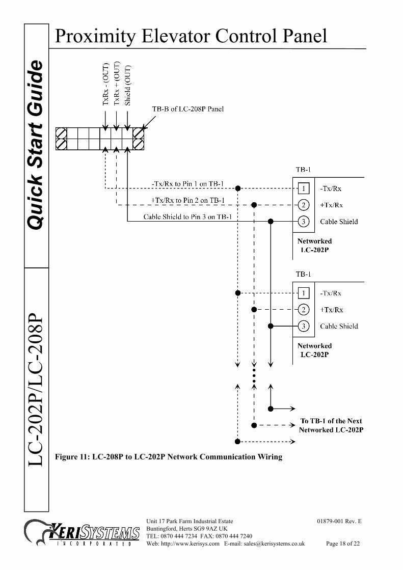
3. Daisy-chain the TxRx+, TxRx-, and Shield Network Communication connections from the terminal strip on the LC-208P to each of the LC-202P panels. Make the connections per the information in Table 7 below and Figure 11 on page 18.
4. Refer to Section 5.2.1 on page 9 for the LC-202P floor relay connections.5. Refer to Section 5.2.4 on page 14 for the LC-202P panel power connections.
Table 6: LC-208P to LC-202P
LC-208P Reader Terminal Strip LC-202P TB-5 or TB-6
Reader Antenna Pin 1
Reader Ground Pin 4
Table 7: LC-208P to LC-202P Panel Network Communication Wiring
LC-208P Panel LC-202P TB-1
TxRx- Pin 1
TxRx+ Pin 2
Shield Pin 3
Unit 17 Park Farm Industrial Estate 01879-001 Rev. EBuntingford, Herts SG9 9AZ UKTEL: 0870 444 7234 FAX: 0870 444 7240Web: http://www.kerisys.com E-mail: [email protected] Page 16 of 22

Proximity Elevator Control PanelLC
-202P/LC-208P
Quick Start G
uide
Figure 10: LC-208P to LC-202P Reader Wiring Connections
Unit 17 Park Farm Industrial Estate 01879-001 Rev. EBuntingford, Herts SG9 9AZ UKTEL: 0870 444 7234 FAX: 0870 444 7240Web: http://www.kerisys.com E-mail: [email protected] Page 17 of 22
Proximity Elevator Control PanelQ
uick
Sta
rt G
uide
LC-2
02P/
LC-2
08P
Figure 11: LC-208P to LC-202P Network Communication Wiring
Unit 17 Park Farm Industrial Estate 01879-001 Rev. EBuntingford, Herts SG9 9AZ UKTEL: 0870 444 7234 FAX: 0870 444 7240Web: http://www.kerisys.com E-mail: [email protected] Page 18 of 22

Proximity Elevator Control PanelLC
-202P/LC-208P
Quick Start G
uide
5.4.2 LC-208P/LC-208P CombinationPerform the following wiring instructions to accommodate an elevator application using two LC-208P panels; up to 16 floors (for 32 floors, add a third LC-208P and continue the daisy-chain wiring to the third panel).1. Make a complete set of connections to the first LC-208P panel. Refer to Section 5.3 on page 14 for all connections to the LC-208P. This panel must have the master elevator controller (the controller with address 1).
2. Daisy-chain the Antenna and Ground reader connections from the terminal strip on the first panel to the terminal strip on the second panel. Make the connections per the information in Table 8 and Figure 12.
Figure 12: LC-208P to LC-208P Wiring Connections
Table 8: LC-208P to LC-208P
First LC-208P Reader Terminal Strip
Second LC-208P Reader Terminal Strip
Reader Antenna Reader Antenna
Reader Ground Reader Ground
Unit 17 Park Farm Industrial Estate 01879-001 Rev. EBuntingford, Herts SG9 9AZ UKTEL: 0870 444 7234 FAX: 0870 444 7240Web: http://www.kerisys.com E-mail: [email protected] Page 19 of 22

Proximity Elevator Control PanelQ
uick
Sta
rt G
uide
LC-2
02P/
LC-2
08P
3. Daisy-chain the TxRx+, TxRx-, and Shield Network Communication connections from the terminal strip on the first panel to the terminal strip on the second panel. Make the connections per the information in Table 9 and Figure 13.
Figure 13: LC-208P to LC-208P Nework Communication Wiring
4. The floor/relay connections for the second LC-208P are made according to the floor/panel association. Refer to Section 5.3 on page 14 for all floor/relay connections to the LC-208P. Power connections are made per the instructions in Section 5.2.4 on page 14.
Table 9: LC-208P to LC-208P Nework Communication Wiring
TB-B on First LC-208P TB-C on Second LC-208P
TxRx- TxRx-
TxRx+ TxRx+
Shield Shield
Unit 17 Park Farm Industrial Estate 01879-001 Rev. EBuntingford, Herts SG9 9AZ UKTEL: 0870 444 7234 FAX: 0870 444 7240Web: http://www.kerisys.com E-mail: [email protected] Page 20 of 22

Proximity Elevator Control PanelLC
-202P/LC-208P
Quick Start G
uide
5.5 Host Computer Wiring ConnectionsThe wiring connections between the Host Computer and the access control/elevator control network are thoroughly described in the PXL-250/SB-293 Technical Reference Manual (P/N 01836-003) and the PXL-250 Quick Start Guide (P/N 01835-002). Please refer to these documents for information regarding host computer/network connections.6.0 Elevator Reader Responses to Access Control EventsDuring day-to-day activity, the reader in the elevator car will respond to access control events in a specific manner. Refer to Table 10 for a summary of the Reader’s LED and beeper actions during access control events.
Table 10: Reader Responses to Access Control Events
Event LED Status Beeper Status
waiting for card presentation displays a steady Amber LED silent
upon card presentation flashes a Green LED one short beep
Unit 17 Park Farm Industrial Estate 01879-001 Rev. EBuntingford, Herts SG9 9AZ UKTEL: 0870 444 7234 FAX: 0870 444 7240Web: http://www.kerisys.com E-mail: [email protected] Page 21 of 22

Proximity Elevator Control PanelQ
uick
Sta
rt G
uide
LC-2
02P/
LC-2
08P
This page is intentionally left blank.
Unit 17 Park Farm Industrial Estate 01879-001 Rev. EBuntingford, Herts SG9 9AZ UKTEL: 0870 444 7234 FAX: 0870 444 7240Web: http://www.kerisys.com E-mail: [email protected] Page 22 of 22