Prowirl 72 PROFIBUS-PA - Axon AutomationH Literature/Manuals/menu... · Brief operating...
176
BA085D/06/en/01.07 71040780 valid as of version V 1.03.XX (device software) Proline Prowirl 72 PROFIBUS PA Vortex Flow Measuring System 8 Operating Instructions
Transcript of Prowirl 72 PROFIBUS-PA - Axon AutomationH Literature/Manuals/menu... · Brief operating...

BA085D/06/en/01.07
71040780
valid as of version
V 1.03.XX (device software)
Proline Prowirl 72
PROFIBUS PA
Vortex Flow Measuring System
8
Operating Instructions
Brief operating instructions Proline Prowirl 72 PROFIBUS PA
2 Endress + Hauser
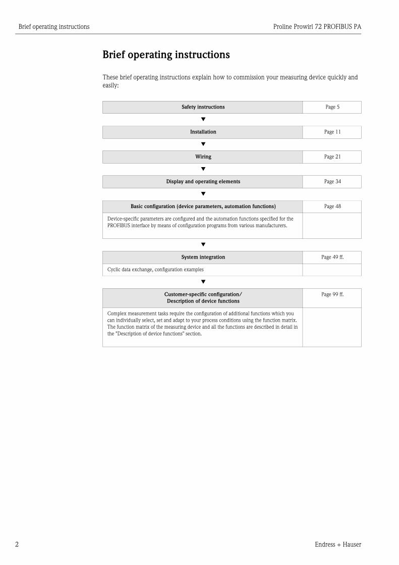
Brief operating instructions
These brief operating instructions explain how to commission your measuring device quickly and
easily:
Safety instructions Page 5
▼
Installation Page 11
▼
Wiring Page 21
▼
Display and operating elements Page 34
▼
Basic configuration (device parameters, automation functions) Page 48
Device-specific parameters are configured and the automation functions specified for the
PROFIBUS interface by means of configuration programs from various manufacturers.
▼
System integration Page 49 ff.
Cyclic data exchange, configuration examples
▼
Customer-specific configuration/
Description of device functions
Page 99 ff.
Complex measurement tasks require the configuration of additional functions which you
can individually select, set and adapt to your process conditions using the function matrix.
The function matrix of the measuring device and all the functions are described in detail in
the "Description of device functions" section.
Proline Prowirl 72 PROFIBUS PA Table of contents
Endress+Hauser 3
Table of contents
Brief operating instructions . . . . . . . . . . . . . 2
Table of contents . . . . . . . . . . . . . . . . . . . . . 3
1 Safety instructions . . . . . . . . . . . . . . . . 5
1.1 Designated use . . . . . . . . . . . . . . . . . . . . . . . . . . . . 5
1.2 Installation, commissioning and operation . . . . . . . . 5
1.3 Operational safety . . . . . . . . . . . . . . . . . . . . . . . . . . 5
1.4 Return . . . . . . . . . . . . . . . . . . . . . . . . . . . . . . . . . . . 6
1.5 Notes on safety conventions and icons . . . . . . . . . . . 6
2 Identification . . . . . . . . . . . . . . . . . . . . 7
2.1 Device designation . . . . . . . . . . . . . . . . . . . . . . . . . 7
2.1.1 Nameplate of the transmitter/sensor . . . . . . 7
2.1.2 Nameplate of the sensor, remote version . . . 8
2.1.3 Service nameplate . . . . . . . . . . . . . . . . . . . . 8
2.2 Certificates and approvals . . . . . . . . . . . . . . . . . . . . 9
2.3 Registered trademarks . . . . . . . . . . . . . . . . . . . . . . . 9
3 Installation . . . . . . . . . . . . . . . . . . . . 11
3.1 Incoming acceptance, transport, storage . . . . . . . . . 11
3.1.1 Incoming acceptance . . . . . . . . . . . . . . . . . 11
3.1.2 Transport . . . . . . . . . . . . . . . . . . . . . . . . . 11
3.1.3 Storage . . . . . . . . . . . . . . . . . . . . . . . . . . . 11
3.2 Installation conditions . . . . . . . . . . . . . . . . . . . . . . 12
3.2.1 Dimensions . . . . . . . . . . . . . . . . . . . . . . . . 12
3.2.2 Installation location . . . . . . . . . . . . . . . . . . 12
3.2.3 Orientation . . . . . . . . . . . . . . . . . . . . . . . . 13
3.2.4 Heat insulation . . . . . . . . . . . . . . . . . . . . . 14
3.2.5 Inlet and outlet run . . . . . . . . . . . . . . . . . . 15
3.2.6 Vibrations . . . . . . . . . . . . . . . . . . . . . . . . . 16
3.2.7 Limiting flow . . . . . . . . . . . . . . . . . . . . . . . 16
3.3 Installation . . . . . . . . . . . . . . . . . . . . . . . . . . . . . . 17
3.3.1 Mounting sensor . . . . . . . . . . . . . . . . . . . . 17
3.3.2 Rotating the transmitter housing . . . . . . . . 18
3.3.3 Rotating the local display . . . . . . . . . . . . . . 18
3.3.4 Mounting transmitter (remote) . . . . . . . . . 19
3.4 Post-installation check . . . . . . . . . . . . . . . . . . . . . . 20
4 Wiring . . . . . . . . . . . . . . . . . . . . . . . . 21
4.1 PROFIBUS PA cable specifications . . . . . . . . . . . . . 21
4.1.1 Shielding and grounding . . . . . . . . . . . . . . 23
4.2 Connecting the remote version . . . . . . . . . . . . . . . 23
4.2.1 Connecting the sensor . . . . . . . . . . . . . . . . 23
4.2.2 Cable specifications . . . . . . . . . . . . . . . . . . 24
4.3 Connecting the measuring unit . . . . . . . . . . . . . . . 25
4.3.1 Connecting the transmitter . . . . . . . . . . . . 25
4.3.2 Terminal assignment . . . . . . . . . . . . . . . . . 28
4.3.3 Fieldbus connector . . . . . . . . . . . . . . . . . . 28
4.4 Degree of protection . . . . . . . . . . . . . . . . . . . . . . . 30
4.5 Post-connection check . . . . . . . . . . . . . . . . . . . . . . 31
5 Operation . . . . . . . . . . . . . . . . . . . . . 33
5.1 Quick operation guide . . . . . . . . . . . . . . . . . . . . . . 33
5.2 Display elements . . . . . . . . . . . . . . . . . . . . . . . . . . 34
5.2.1 Display symbols . . . . . . . . . . . . . . . . . . . . . 34
5.3 Error message display . . . . . . . . . . . . . . . . . . . . . . . 35
5.3.1 Type of error . . . . . . . . . . . . . . . . . . . . . . . 35
5.3.2 Type of error message . . . . . . . . . . . . . . . . 35
5.4 Operating options . . . . . . . . . . . . . . . . . . . . . . . . . 36
5.4.1 Operating program
"ToF Tool Fieldtool Package" . . . . . . . . . . . 36
5.4.2 Operating program
"FieldCare" . . . . . . . . . . . . . . . . . . . . . . . . 36
5.4.3 Operating program
"SIMATIC PDM" (Siemens) . . . . . . . . . . . . 36
5.4.4 Commuwin II operating program . . . . . . . . 37
5.4.5 Current device description files . . . . . . . . . 44
5.5 Hardware configuration . . . . . . . . . . . . . . . . . . . . . 45
5.5.1 Switching write protection on/off . . . . . . . 45
5.5.2 Configuring the device address . . . . . . . . . . 46
6 Commissioning . . . . . . . . . . . . . . . . . 47
6.1 Function check . . . . . . . . . . . . . . . . . . . . . . . . . . . 47
6.1.1 Switching on the measuring device . . . . . . 47
6.2 Commissioning the PROFIBUS interface . . . . . . . . . 48
6.2.1 Commissioning via the Class 2 master . . . . 48
6.3 System integration . . . . . . . . . . . . . . . . . . . . . . . . . 49
6.3.1 Compatibility with
previous model Prowirl 77 . . . . . . . . . . . . . 52
6.4 Cyclic data exchange . . . . . . . . . . . . . . . . . . . . . . . 53
6.4.1 Configuration examples with
Simatic S7 HW-Konfig . . . . . . . . . . . . . . . . 58
6.5 Acyclic data exchange . . . . . . . . . . . . . . . . . . . . . . 63
6.5.1 Class 2 master acyclic (MS2AC) . . . . . . . . . 63
6.5.2 Class 1 master acyclic (MS1AC) . . . . . . . . . 63
7 Maintenance . . . . . . . . . . . . . . . . . . . 65
8 Accessories . . . . . . . . . . . . . . . . . . . . 67
9 Troubleshooting . . . . . . . . . . . . . . . . 69
9.1 Troubleshooting instructions . . . . . . . . . . . . . . . . . 69
9.2 System error messages . . . . . . . . . . . . . . . . . . . . . . 71
9.3 Process error messages . . . . . . . . . . . . . . . . . . . . . . 73
9.4 Process errors without messages . . . . . . . . . . . . . . 74
9.5 Spare parts . . . . . . . . . . . . . . . . . . . . . . . . . . . . . . . 76
9.6 Installing and removing electronics boards . . . . . . . 77
9.6.1 Non-Ex / Ex i/IS and Ex n version . . . . . . 77
9.6.2 Ex d/XP version . . . . . . . . . . . . . . . . . . . . 79
9.7 Software history . . . . . . . . . . . . . . . . . . . . . . . . . . . 81
Table of contents Proline Prowirl 72 PROFIBUS PA
4 Endress+Hauser
10 Technical data . . . . . . . . . . . . . . . . . . 83
10.1 Technical data at a glance . . . . . . . . . . . . . . . . . . . 83
10.1.1 Application . . . . . . . . . . . . . . . . . . . . . . . . 83
10.1.2 Function and system design . . . . . . . . . . . 83
10.1.3 Input . . . . . . . . . . . . . . . . . . . . . . . . . . . . 83
10.1.4 PROFIBUS PA output . . . . . . . . . . . . . . . . 84
10.1.5 Power supply . . . . . . . . . . . . . . . . . . . . . . 85
10.1.6 Performance characteristics . . . . . . . . . . . 85
10.1.7 Operating conditions: Installation . . . . . . . 87
10.1.8 Operating conditions: Environment . . . . . . 87
10.1.9 Operating conditions: Process . . . . . . . . . . 88
10.1.10Frequency ranges for air and water . . . . . . 91
10.1.11Mechanical construction . . . . . . . . . . . . . . 93
10.1.12Human interface . . . . . . . . . . . . . . . . . . . . 94
10.1.13Certificates and approvals . . . . . . . . . . . . . 94
10.1.14Accessories . . . . . . . . . . . . . . . . . . . . . . . . 95
10.1.15Documentation . . . . . . . . . . . . . . . . . . . . 95
10.2 Dimensions of flow conditioner . . . . . . . . . . . . . . 96
11 Operation via PROFIBUS PA . . . . . . . 99
11.1 Block model . . . . . . . . . . . . . . . . . . . . . . . . . . . . . 99
11.2 Physical Block (device block) . . . . . . . . . . . . . . . 100
11.2.1 Write protection . . . . . . . . . . . . . . . . . . . 100
11.2.2 Physical Block parameters . . . . . . . . . . . . 100
11.3 Transducer Block . . . . . . . . . . . . . . . . . . . . . . . . 105
11.3.1 Signal processing . . . . . . . . . . . . . . . . . . 106
11.3.2 Block output variables . . . . . . . . . . . . . . 106
11.3.3 Alarm detection and processing . . . . . . . 106
11.3.4 Accessing the manufacturer-specific
parameters . . . . . . . . . . . . . . . . . . . . . . . 106
11.3.5 Transducer Block parameters . . . . . . . . . 107
11.4 Function blocks, general . . . . . . . . . . . . . . . . . . . 136
11.5 Analog Input function block . . . . . . . . . . . . . . . . 137
11.5.1 Signal processing . . . . . . . . . . . . . . . . . . 137
11.5.2 Selecting the operating mode . . . . . . . . . 138
11.5.3 Selecting the units . . . . . . . . . . . . . . . . . 138
11.5.4 Status of the OUT output value . . . . . . . . 138
11.5.5 Simulation of input/output . . . . . . . . . . . 138
11.5.6 Failsafe mode FAILSAFE TYPE . . . . . . . . 139
11.5.7 Rescaling the input value . . . . . . . . . . . . 139
11.5.8 Limit values . . . . . . . . . . . . . . . . . . . . . . 140
11.5.9 Alarm detection and processing . . . . . . . 140
11.5.10Analog Input function block parameters . 140
11.6 Totalizer function block . . . . . . . . . . . . . . . . . . . 150
11.6.1 Signal processing . . . . . . . . . . . . . . . . . . 150
11.6.2 Selecting the operating mode . . . . . . . . . 150
11.6.3 Unit of the totaled measured value
UNIT TOT . . . . . . . . . . . . . . . . . . . . . . . 151
11.6.4 Status of the TOTAL output value . . . . . . 151
11.6.5 Failsafe mode FAIL TOT . . . . . . . . . . . . . 151
11.6.6 Selecting the direction for totaling,
MODE TOT . . . . . . . . . . . . . . . . . . . . . . 151
11.6.7 Initial setting of the totalizer SET TOT . . 152
11.6.8 Limit values . . . . . . . . . . . . . . . . . . . . . . 152
11.6.9 Alarm detection and processing . . . . . . . 153
11.6.10Totalizer function block parameters . . . . 153
11.7 Slot/Index lists . . . . . . . . . . . . . . . . . . . . . . . . . . 162
11.7.1 General explanatory remarks . . . . . . . . . . 162
11.7.2 Device management slot 1 . . . . . . . . . . . 162
11.7.3 Physical Block slot 0 . . . . . . . . . . . . . . . . 162
11.7.4 Transducer Block slot 1 . . . . . . . . . . . . . . 164
11.7.5 AI 1 Volume Flow Block slot 1 . . . . . . . . 167
11.7.6 Totalizer 1 Block slot 2 . . . . . . . . . . . . . . 168
12 Factory settings . . . . . . . . . . . . . . . . 169
12.1 Metric units (not for USA and Canada) . . . . . . . . 169
12.2 US units (only for USA and Canada) . . . . . . . . . . 170
Stichwortverzeichnis . . . . . . . . . . . . . . . . . 171
Proline Prowirl 72 PROFIBUS PA 1 Safety instructions
Endress + Hauser 5
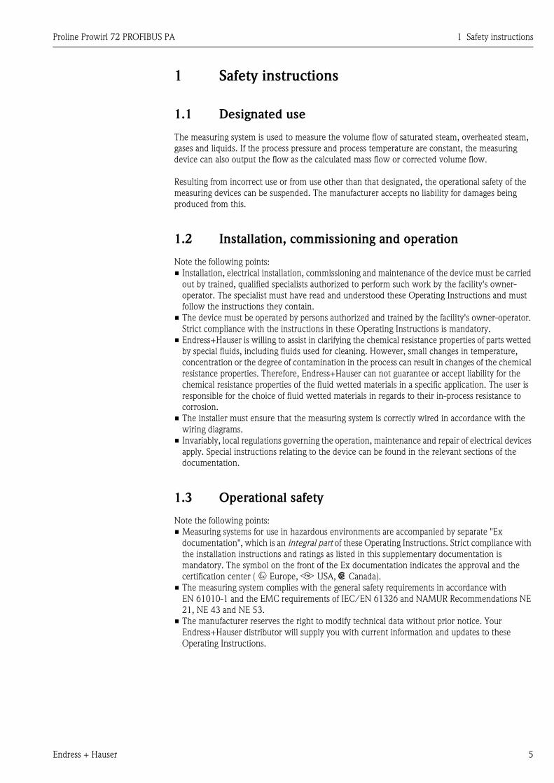
1 Safety instructions
1.1 Designated use
The measuring system is used to measure the volume flow of saturated steam, overheated steam,
gases and liquids. If the process pressure and process temperature are constant, the measuring
device can also output the flow as the calculated mass flow or corrected volume flow.
Resulting from incorrect use or from use other than that designated, the operational safety of the
measuring devices can be suspended. The manufacturer accepts no liability for damages being
produced from this.
1.2 Installation, commissioning and operation
Note the following points:
• Installation, electrical installation, commissioning and maintenance of the device must be carried
out by trained, qualified specialists authorized to perform such work by the facility's owner-
operator. The specialist must have read and understood these Operating Instructions and must
follow the instructions they contain.
• The device must be operated by persons authorized and trained by the facility's owner-operator.
Strict compliance with the instructions in these Operating Instructions is mandatory.
• Endress+Hauser is willing to assist in clarifying the chemical resistance properties of parts wetted
by special fluids, including fluids used for cleaning. However, small changes in temperature,
concentration or the degree of contamination in the process can result in changes of the chemical
resistance properties. Therefore, Endress+Hauser can not guarantee or accept liability for the
chemical resistance properties of the fluid wetted materials in a specific application. The user is
responsible for the choice of fluid wetted materials in regards to their in-process resistance to
corrosion.
• The installer must ensure that the measuring system is correctly wired in accordance with the
wiring diagrams.
• Invariably, local regulations governing the operation, maintenance and repair of electrical devices
apply. Special instructions relating to the device can be found in the relevant sections of the
documentation.
1.3 Operational safety
Note the following points:
• Measuring systems for use in hazardous environments are accompanied by separate "Ex
documentation", which is an integral part of these Operating Instructions. Strict compliance with
the installation instructions and ratings as listed in this supplementary documentation is
mandatory. The symbol on the front of the Ex documentation indicates the approval and the
certification center ( 0 Europe, 2 USA, 1 Canada).
• The measuring system complies with the general safety requirements in accordance with
EN 61010-1 and the EMC requirements of IEC/EN 61326 and NAMUR Recommendations NE
21, NE 43 and NE 53.
• The manufacturer reserves the right to modify technical data without prior notice. Your
Endress+Hauser distributor will supply you with current information and updates to these
Operating Instructions.
1 Safety instructions Proline Prowirl 72 PROFIBUS PA
6 Endress + Hauser
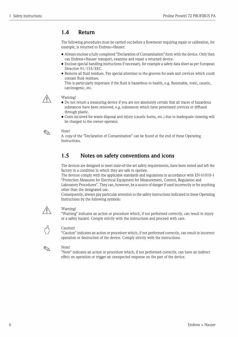
1.4 Return
The following procedures must be carried out before a flowmeter requiring repair or calibration, for
example, is returned to Endress+Hauser:
• Always enclose a fully completed "Declaration of Contamination" form with the device. Only then
can Endress+Hauser transport, examine and repair a returned device.
• Enclose special handling instructions if necessary, for example a safety data sheet as per European
Directive 91/155/EEC.
• Remove all fluid residues. Pay special attention to the grooves for seals and crevices which could
contain fluid residues.
This is particularly important if the fluid is hazardous to health, e.g. flammable, toxic, caustic,
carcinogenic, etc.
# Warning!
• Do not return a measuring device if you are not absolutely certain that all traces of hazardous
substances have been removed, e.g. substances which have penetrated crevices or diffused
through plastic.
• Costs incurred for waste disposal and injury (caustic burns, etc.) due to inadequate cleaning will
be charged to the owner-operator.
! Note!
A copy of the "Declaration of Contamination" can be found at the end of these Operating
Instructions.
1.5 Notes on safety conventions and icons
The devices are designed to meet state-of-the-art safety requirements, have been tested and left the
factory in a condition in which they are safe to operate.
The devices comply with the applicable standards and regulations in accordance with EN 61010-1
"Protection Measures for Electrical Equipment for Measurement, Control, Regulation and
Laboratory Procedures". They can, however, be a source of danger if used incorrectly or for anything
other than the designated use.
Consequently, always pay particular attention to the safety instructions indicated in these Operating
Instructions by the following symbols:
# Warning!
"Warning" indicates an action or procedure which, if not performed correctly, can result in injury
or a safety hazard. Comply strictly with the instructions and proceed with care.
" Caution!
"Caution" indicates an action or procedure which, if not performed correctly, can result in incorrect
operation or destruction of the device. Comply strictly with the instructions.
! Note!
"Note" indicates an action or procedure which, if not performed correctly, can have an indirect
effect on operation or trigger an unexpected response on the part of the device.
Proline Prowirl 72 PROFIBUS PA 2 Identification
Endress + Hauser 7
2 Identification
2.1 Device designation
The "Proline Prowirl 72 PROFIBUS PA" flowmeter system consists of the following components:
• Transmitter Proline Prowirl 72 PROFIBUS PA
• Prowirl F or Prowirl W sensor
In the compact version, the transmitter and sensor form a mechanical unit; in the remote version
they are mounted separate from one another.
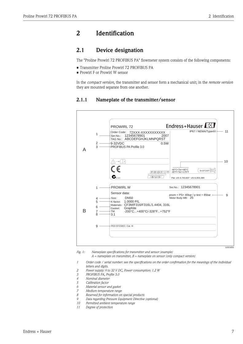
2.1.1 Nameplate of the transmitter/sensor
A0004806
Fig. 1: Nameplate specifications for transmitter and sensor (example)
A = nameplate on transmitter, B = nameplate on sensor (only compact version)
1 Order code / serial number: see the specifications on the order confirmation for the meanings of the individual
letters and digits.
2 Power supply: 9 to 32 V DC, Power consumption: 1.2 W
3 PROFIBUS PA, Profile 3.0
4 Nominal diameter
5 Calibration factor
6 Material sensor and gasket
7 Medium temperature range
8 Reserved for information on special products
9 Data regarding Pressure Equipment Directive (optional)
10 Permitted ambient temperature range
11 Degree of protection
1
4
9
5
6
78
B
9
3.1
K-factor:
Gasket:TM:
Materials: CF3M/F316/F316L/1.4404, 316LGraphite-200°C...+400°C/-328°F...+752°F
1.0000 P/L
Sensor data:
Ser.No.: 12345678901PROWIRL W
DN50Size:
PED 97/23/EC: Cat. III
pnom = PS= 40bar / p test = 85barMeter Body MB: 25
PROWIRL 72
ABCDEFGHJKLMNPQRSTTAG No.:
Ser.No.: 12345678901Order Code:
i
IP67 / NEMA/Type4X
-40°F<Ta<+176°FTa+10°C/18°F
72XXX-XXXXXXXXXXX
9-32VDC
Pat. US 4,743,837 US 6,003,384
PROFIBUS PA Profile 3.00.5W
-40°C<Ta<+80°C
B
P
U S
R O IF R
2007
N12895
1
23
A
10
11
2 Identification Proline Prowirl 72 PROFIBUS PA
8 Endress + Hauser
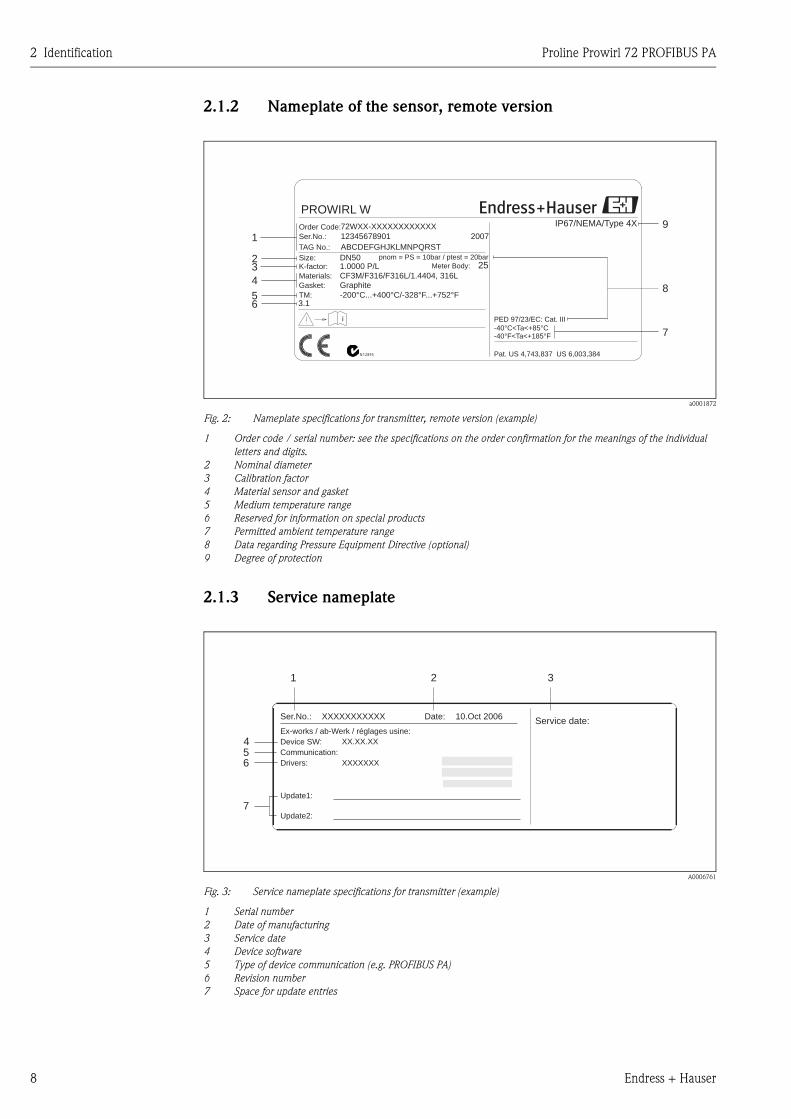
2.1.2 Nameplate of the sensor, remote version
a0001872
Fig. 2: Nameplate specifications for transmitter, remote version (example)
1 Order code / serial number: see the specifications on the order confirmation for the meanings of the individual
letters and digits.
2 Nominal diameter
3 Calibration factor
4 Material sensor and gasket
5 Medium temperature range
6 Reserved for information on special products
7 Permitted ambient temperature range
8 Data regarding Pressure Equipment Directive (optional)
9 Degree of protection
2.1.3 Service nameplate
A0006761
Fig. 3: Service nameplate specifications for transmitter (example)
1 Serial number
2 Date of manufacturing
3 Service date
4 Device software
5 Type of device communication (e.g. PROFIBUS PA)
6 Revision number
7 Space for update entries
ABCDEFGHJKLMNPQRSTTAG No.:
Ser.No.: 12345678901Order Code:
Pat. US 4,743,837 US 6,003,384
i
IP67/NEMA/Type 4X
-40°C<Ta<+85°C-40°F<Ta<+185°F
Gasket:
TM:
Graphite
-200°C...+400°C/-328°F...+752°F
72WXX-XXXXXXXXXXXX
K-factor: 1.0000 P/LMaterials: CF3M/F316/F316L/1.4404, 316L
PROWIRL W
3.1
Size: DN50
PED 97/23/EC: Cat. III
2007
N12895
pnom = PS = 10bar / ptest = 20bar
1
23
4
6
7
9
58
Meter Body: 25
Service date:XXXXXXXXXXXSer.No.:
Ex-works / ab-Werk / réglages usine:
Date: 10.Oct 2006
XX.XX.XXDevice SW:
Communication:
XXXXXXXDrivers:
Update2:
Update1:
1 2 3
456
7
Proline Prowirl 72 PROFIBUS PA 2 Identification
Endress + Hauser 9
2.2 Certificates and approvals
The devices are designed according to good engineering practice to meet state-of-the-art safety
requirements, have been tested and left the factory in a condition in which they are safe to operate.
The devices comply with the applicable standards and regulations in accordance with EN 61010-1
"Protection Measures for Electrical Equipment for Measurement, Control, Regulation and
Laboratory Procedures" and the EMC requirements as per IEC/EN 61326.
The measuring system described in these Operating Instructions complies with the legal
requirements of the EU Directives. Endress+Hauser confirms this by affixing the CE mark to it and
by issuing the CE declaration of conformity.
The measuring system meets the EMC requirements of the "Australian Communications and Media
Authority (ACMA)".
2.3 Registered trademarks
GYLON ®
Registered trademark of Garlock Sealing Technologies, Palmyar, NY, USA
PROFIBUS ®
Registered trademark of PROFIBUS User Organization e.V., Karlsruhe, Germany
INCONEL ®
Registered trademark of Inco Alloys International Inc., Huntington, USA
KALREZ ®, VITON ®
Registered trademarks of E.I. Du Pont de Nemours & Co., Wilmington, USA
Fieldcheck®, Applicator®, ToF Tool - Fieldtool® Package
Registered or registration-pending trademarks of Endress+Hauser Flowtec AG, Reinach,
Switzerland

2 Identification Proline Prowirl 72 PROFIBUS PA
10 Endress + Hauser
Proline Prowirl 72 PROFIBUS PA 3 Installation
Endress + Hauser 11
3 Installation
3.1 Incoming acceptance, transport, storage
3.1.1 Incoming acceptance
On receipt of the goods, check the following points:
• Check the packaging and the contents for damage.
• Check the shipment, make sure nothing is missing and that the scope of supply matches your
order.
3.1.2 Transport
Please note the following when unpacking or transporting to the measuring point:
• The devices must be transported in the container supplied.
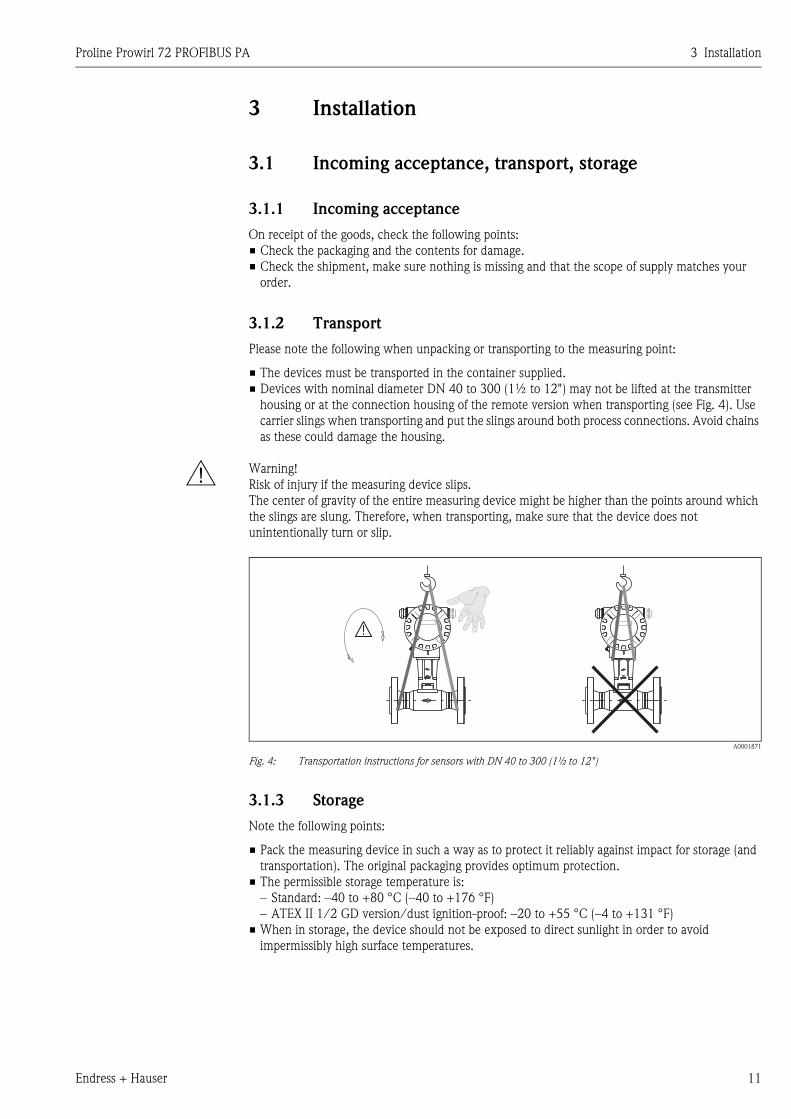
• Devices with nominal diameter DN 40 to 300 (1½ to 12") may not be lifted at the transmitter
housing or at the connection housing of the remote version when transporting (see Fig. 4). Use
carrier slings when transporting and put the slings around both process connections. Avoid chains
as these could damage the housing.
# Warning!
Risk of injury if the measuring device slips.
The center of gravity of the entire measuring device might be higher than the points around which
the slings are slung. Therefore, when transporting, make sure that the device does not
unintentionally turn or slip.
A0001871
Fig. 4: Transportation instructions for sensors with DN 40 to 300 (1½ to 12")
3.1.3 Storage
Note the following points:
• Pack the measuring device in such a way as to protect it reliably against impact for storage (and
transportation). The original packaging provides optimum protection.
• The permissible storage temperature is:
– Standard: –40 to +80 °C (–40 to +176 °F)
– ATEX II 1/2 GD version/dust ignition-proof: –20 to +55 °C (–4 to +131 °F)
• When in storage, the device should not be exposed to direct sunlight in order to avoid
impermissibly high surface temperatures.
3 Installation Proline Prowirl 72 PROFIBUS PA
12 Endress + Hauser
3.2 Installation conditions
Note the following points:
• The measuring device requires a fully developed flow profile as a prerequisite for correct volume
flow measurement. The inlet and outlet runs must be taken into account (see Page 15).
• The maximum permitted ambient temperatures (see Page 87) and fluid temperatures (see
Page 88) must be observed.
• Pay particular attention to the notes on orientation and piping insulation (see Page 13).
• Verify that the correct nominal diameter and pipe standard (DIN/JIS/ANSI) were taken into
account when ordering since the calibration of the device and the achievable accuracy depend on
these factors. If the mating pipe and the device have different nominal diameters/pipe standards,
an inlet correction can be made via the device software by entering the actual pipe diameter (see
MATING PIPE DIAMETER function on Page 119).
• The correct operation of the measuring system is not influenced by plant vibrations up to 1 g,
10 to 500 Hz.
• For mechanical reasons, and in order to protect the piping, it is advisable to support heavy sensors.
For weight information, please refer to Technical Information TI070D/06/en.
3.2.1 Dimensions
The dimensions and lengths of the sensor and transmitter can be found in the Technical Information
TI070D/06/en.
3.2.2 Installation location
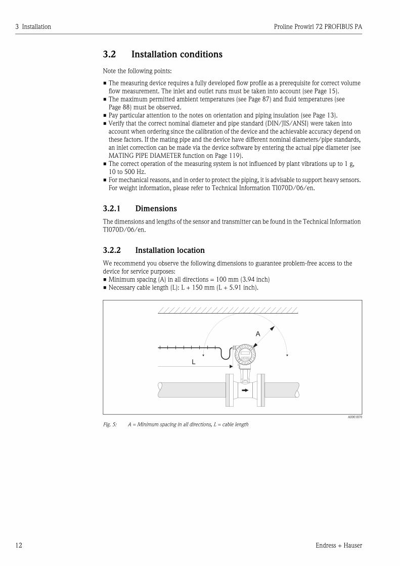
We recommend you observe the following dimensions to guarantee problem-free access to the
device for service purposes:
• Minimum spacing (A) in all directions = 100 mm (3.94 inch)
• Necessary cable length (L): L + 150 mm (L + 5.91 inch).
A0001870
Fig. 5: A = Minimum spacing in all directions, L = cable length
L
A
Proline Prowirl 72 PROFIBUS PA 3 Installation
Endress + Hauser 13
3.2.3 Orientation
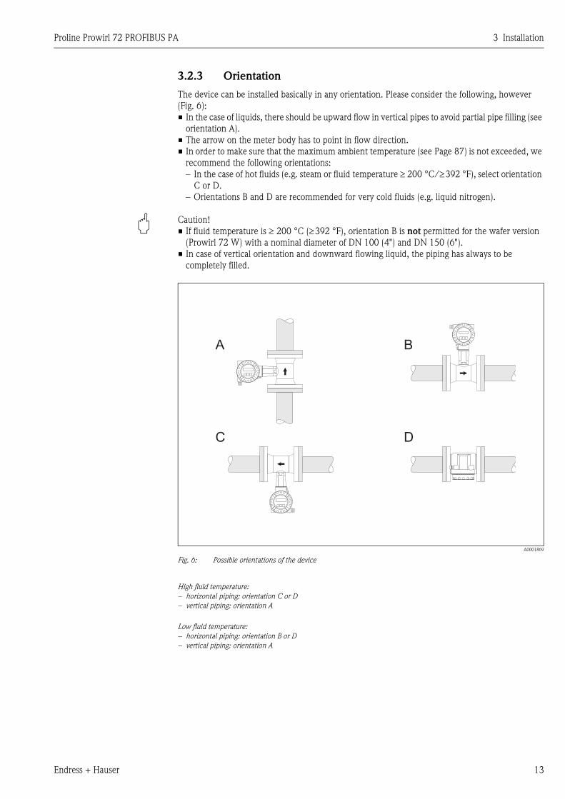
The device can be installed basically in any orientation. Please consider the following, however
(Fig. 6):
• In the case of liquids, there should be upward flow in vertical pipes to avoid partial pipe filling (see
orientation A).
• The arrow on the meter body has to point in flow direction.
• In order to make sure that the maximum ambient temperature (see Page 87) is not exceeded, we
recommend the following orientations:
– In the case of hot fluids (e.g. steam or fluid temperature ≥ 200 °C/≥392 °F), select orientation
C or D.
– Orientations B and D are recommended for very cold fluids (e.g. liquid nitrogen).
" Caution!
• If fluid temperature is ≥ 200 °C (≥392 °F), orientation B is not permitted for the wafer version
(Prowirl 72 W) with a nominal diameter of DN 100 (4") and DN 150 (6").
• In case of vertical orientation and downward flowing liquid, the piping has always to be
completely filled.
A0001869
Fig. 6: Possible orientations of the device
High fluid temperature:
– horizontal piping: orientation C or D
– vertical piping: orientation A
Low fluid temperature:
– horizontal piping: orientation B or D
– vertical piping: orientation A
B
D
A
C
3 Installation Proline Prowirl 72 PROFIBUS PA
14 Endress + Hauser
3.2.4 Heat insulation
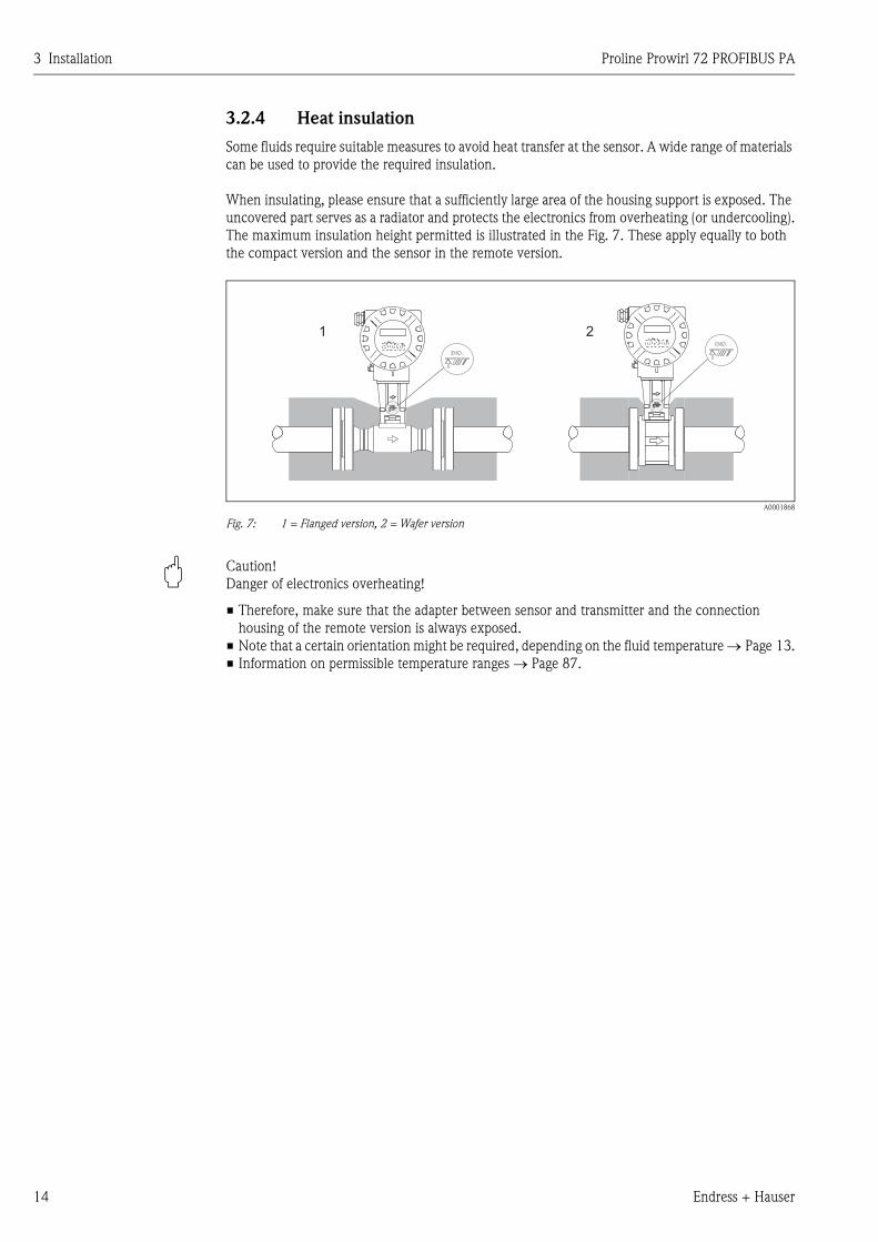
Some fluids require suitable measures to avoid heat transfer at the sensor. A wide range of materials
can be used to provide the required insulation.
When insulating, please ensure that a sufficiently large area of the housing support is exposed. The
uncovered part serves as a radiator and protects the electronics from overheating (or undercooling).
The maximum insulation height permitted is illustrated in the Fig. 7. These apply equally to both
the compact version and the sensor in the remote version.
A0001868
Fig. 7: 1 = Flanged version, 2 = Wafer version
" Caution!
Danger of electronics overheating!
• Therefore, make sure that the adapter between sensor and transmitter and the connection
housing of the remote version is always exposed.
• Note that a certain orientation might be required, depending on the fluid temperature → Page 13.
• Information on permissible temperature ranges → Page 87.
1 2Esc
E- +Esc
E- +
Proline Prowirl 72 PROFIBUS PA 3 Installation
Endress + Hauser 15
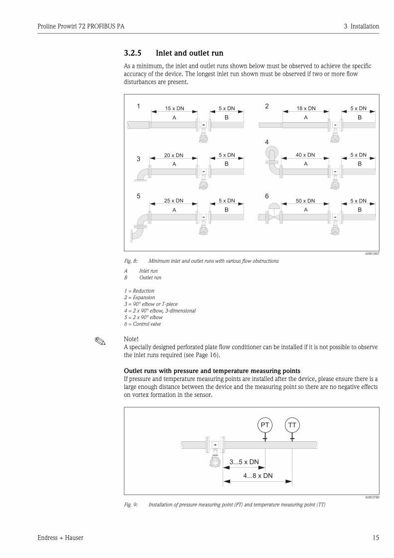
3.2.5 Inlet and outlet run
As a minimum, the inlet and outlet runs shown below must be observed to achieve the specific
accuracy of the device. The longest inlet run shown must be observed if two or more flow
disturbances are present.
A0001867
Fig. 8: Minimum inlet and outlet runs with various flow obstructions
A Inlet run
B Outlet run
1 = Reduction
2 = Expansion
3 = 90° elbow or T-piece
4 = 2 x 90° elbow, 3-dimensional
5 = 2 x 90° elbow
6 = Control valve
! Note!
A specially designed perforated plate flow conditioner can be installed if it is not possible to observe
the inlet runs required (see Page 16).
Outlet runs with pressure and temperature measuring points
If pressure and temperature measuring points are installed after the device, please ensure there is a
large enough distance between the device and the measuring point so there are no negative effects
on vortex formation in the sensor.
A0003780
Fig. 9: Installation of pressure measuring point (PT) and temperature measuring point (TT)
Esc
E- +
Esc
E- +Esc
E- +
Esc
E- +
15 x DN 5 x DN
A
1
3
5
2
4
6
A
A
A
A
A
B
B
B
B
B
B
18 x DN 5 x DN
20 x DN 5 x DN 40 x DN 5 x DN
25 x DN 5 x DN 50 x DN 5 x DN
Esc
E- +Esc
E- +
PT TT
3...5 x DN
4...8 x DN
Esc
E- +
3 Installation Proline Prowirl 72 PROFIBUS PA
16 Endress + Hauser
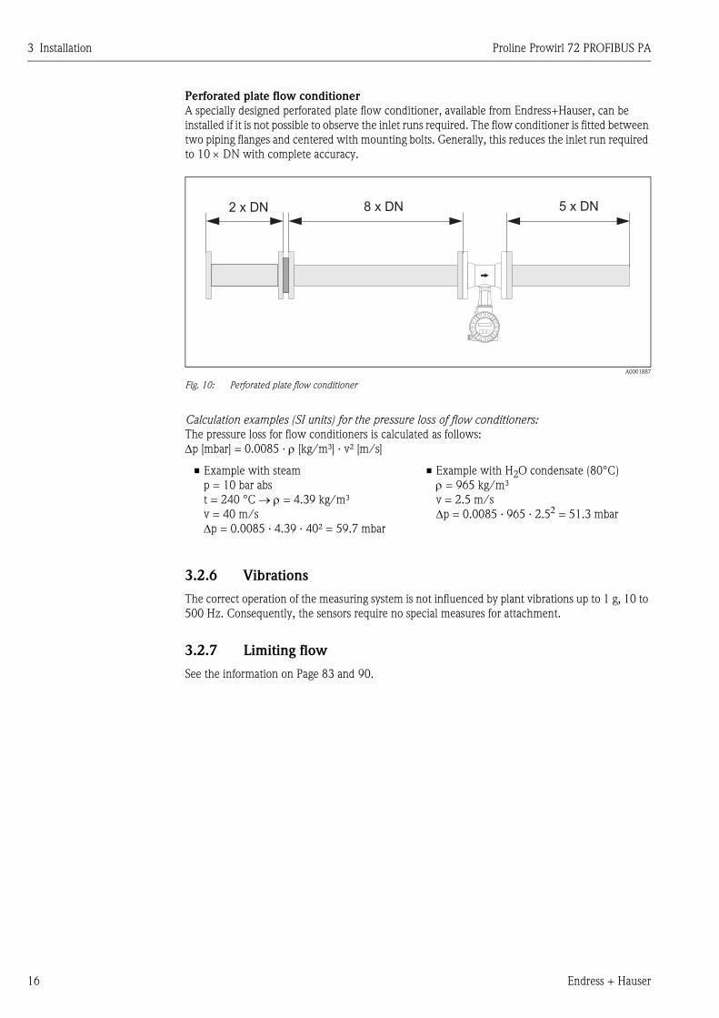
Perforated plate flow conditioner
A specially designed perforated plate flow conditioner, available from Endress+Hauser, can be
installed if it is not possible to observe the inlet runs required. The flow conditioner is fitted between
two piping flanges and centered with mounting bolts. Generally, this reduces the inlet run required
to 10 × DN with complete accuracy.
A0001887
Fig. 10: Perforated plate flow conditioner
Calculation examples (SI units) for the pressure loss of flow conditioners:
The pressure loss for flow conditioners is calculated as follows:
Δp [mbar] = 0.0085 · ρ [kg/m³] · v² [m/s]
3.2.6 Vibrations
The correct operation of the measuring system is not influenced by plant vibrations up to 1 g, 10 to
500 Hz. Consequently, the sensors require no special measures for attachment.
3.2.7 Limiting flow
See the information on Page 83 and 90.
• Example with steam
p = 10 bar abs
t = 240 °C → ρ = 4.39 kg/m³
v = 40 m/s
Δp = 0.0085 · 4.39 · 40² = 59.7 mbar
• Example with H2O condensate (80°C)
ρ = 965 kg/m³
v = 2.5 m/s
Δp = 0.0085 · 965 · 2.52 = 51.3 mbar
8 x DN2 x DN 5 x DN
Proline Prowirl 72 PROFIBUS PA 3 Installation
Endress + Hauser 17
3.3 Installation
3.3.1 Mounting sensor
" Caution!
Please note the following prior to mounting:
• Prior to installing the measuring device in the piping, remove all traces of transport packaging and
any protective covers from the sensor.
• Make sure that the internal diameters of seals are the same as, or greater than, those of the
measuring pipe and piping. Seals projecting into the flow current have a negative effect on the
vortex formation after the bluff body and cause inaccurate measurement. The gaskets provided
by Endress+Hauser for the wafer version have therefore an inner diameter with a bigger inner
diameter than the piping.
• Ensure that the arrow on the measuring pipe matches the direction of flow in the piping.
• Lengths:
– Prowirl W (wafer version): 65 mm (2.56 inch)
– Prowirl F (flanged version) → See Technical Information TI070D/06/en.
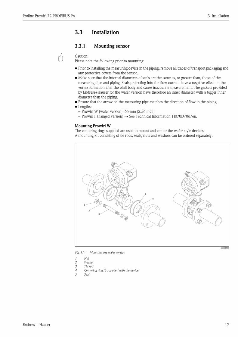
Mounting Prowirl W
The centering rings supplied are used to mount and center the wafer-style devices.
A mounting kit consisting of tie rods, seals, nuts and washers can be ordered separately.
A0001888
Fig. 11: Mounting the wafer version
1 Nut
2 Washer
3 Tie rod
4 Centering ring (is supplied with the device)
5 Seal
1
2
3
4
5
3 Installation Proline Prowirl 72 PROFIBUS PA
18 Endress + Hauser
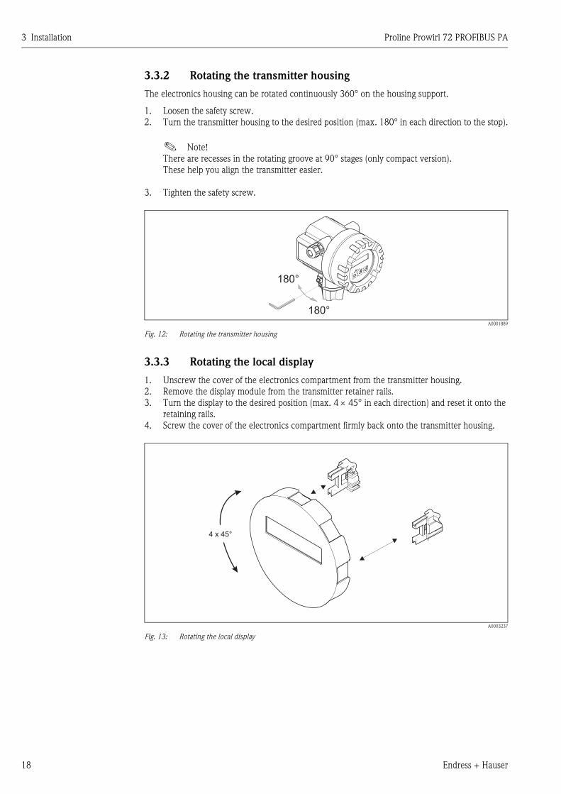
3.3.2 Rotating the transmitter housing
The electronics housing can be rotated continuously 360° on the housing support.
1. Loosen the safety screw.
2. Turn the transmitter housing to the desired position (max. 180° in each direction to the stop).
! Note!
There are recesses in the rotating groove at 90° stages (only compact version).
These help you align the transmitter easier.
3. Tighten the safety screw.
A0001889
Fig. 12: Rotating the transmitter housing
3.3.3 Rotating the local display
1. Unscrew the cover of the electronics compartment from the transmitter housing.
2. Remove the display module from the transmitter retainer rails.
3. Turn the display to the desired position (max. 4 × 45° in each direction) and reset it onto the
retaining rails.
4. Screw the cover of the electronics compartment firmly back onto the transmitter housing.
A0003237
Fig. 13: Rotating the local display
180°
180°
4 x 45°
Proline Prowirl 72 PROFIBUS PA 3 Installation
Endress + Hauser 19
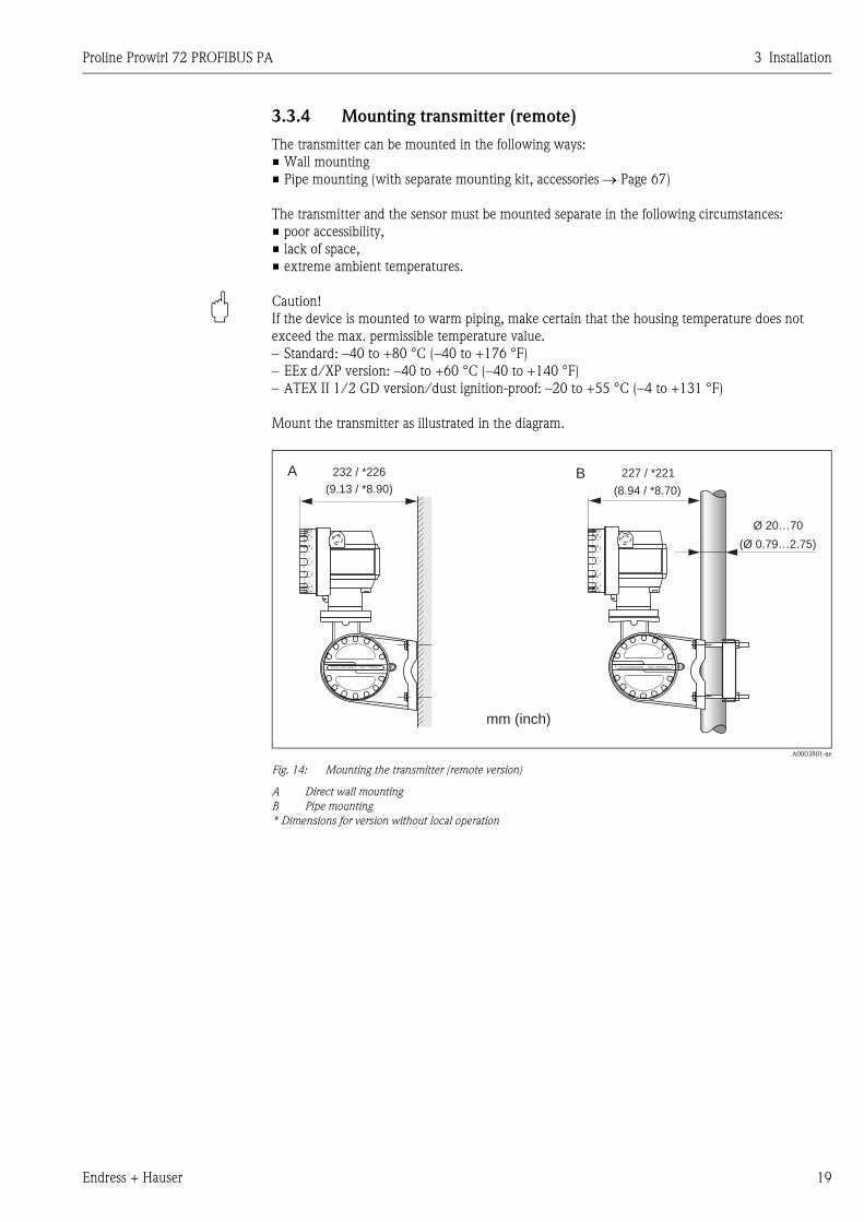
3.3.4 Mounting transmitter (remote)
The transmitter can be mounted in the following ways:
• Wall mounting
• Pipe mounting (with separate mounting kit, accessories → Page 67)
The transmitter and the sensor must be mounted separate in the following circumstances:
• poor accessibility,
• lack of space,
• extreme ambient temperatures.
" Caution!
If the device is mounted to warm piping, make certain that the housing temperature does not
exceed the max. permissible temperature value.
– Standard: –40 to +80 °C (–40 to +176 °F)
– EEx d/XP version: –40 to +60 °C (–40 to +140 °F)
– ATEX II 1/2 GD version/dust ignition-proof: –20 to +55 °C (–4 to +131 °F)
Mount the transmitter as illustrated in the diagram.
A0003801-ae
Fig. 14: Mounting the transmitter (remote version)
A Direct wall mounting
B Pipe mounting
* Dimensions for version without local operation
ANSCHLUSSKLEMMEN - FIELD TERMINALS ANSCHLUSSKLEMMEN - FIELD TERMINALS
A B232 / *226 227 / *221
(9.13 / *8.90) (8.94 / *8.70)
mm (inch)
Ø 20…70
(Ø 0.79…2.75)
3 Installation Proline Prowirl 72 PROFIBUS PA
20 Endress + Hauser
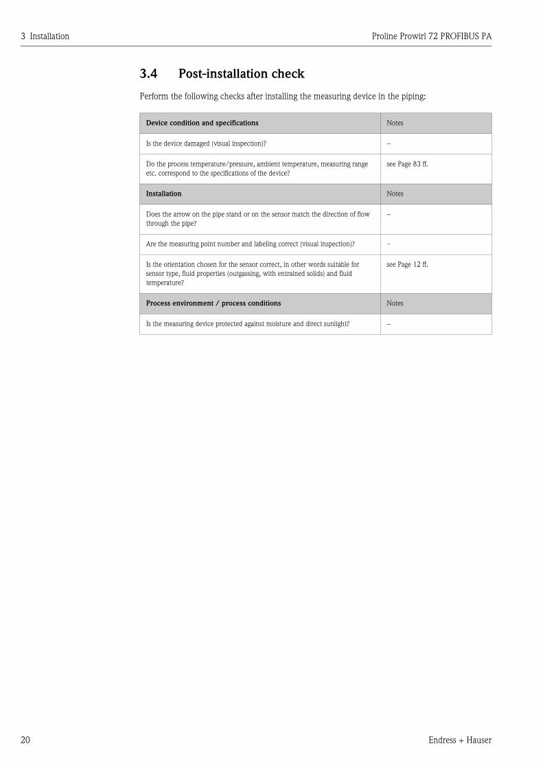
3.4 Post-installation check
Perform the following checks after installing the measuring device in the piping:
Device condition and specifications Notes
Is the device damaged (visual inspection)? −
Do the process temperature/pressure, ambient temperature, measuring range
etc. correspond to the specifications of the device?
see Page 83 ff.
Installation Notes
Does the arrow on the pipe stand or on the sensor match the direction of flow
through the pipe?
−
Are the measuring point number and labeling correct (visual inspection)? –
Is the orientation chosen for the sensor correct, in other words suitable for
sensor type, fluid properties (outgassing, with entrained solids) and fluid
temperature?
see Page 12 ff.
Process environment / process conditions Notes
Is the measuring device protected against moisture and direct sunlight? −
Proline Prowirl 72 PROFIBUS PA 4 Wiring
Endress + Hauser 21
4 Wiring
# Warning!
When connecting Ex-certified devices, please refer to the notes and diagrams in the Ex-specific
supplement to these Operating Instructions. Please do not hesitate to contact your Endress+Hauser
representative if you have any questions.
4.1 PROFIBUS PA cable specifications
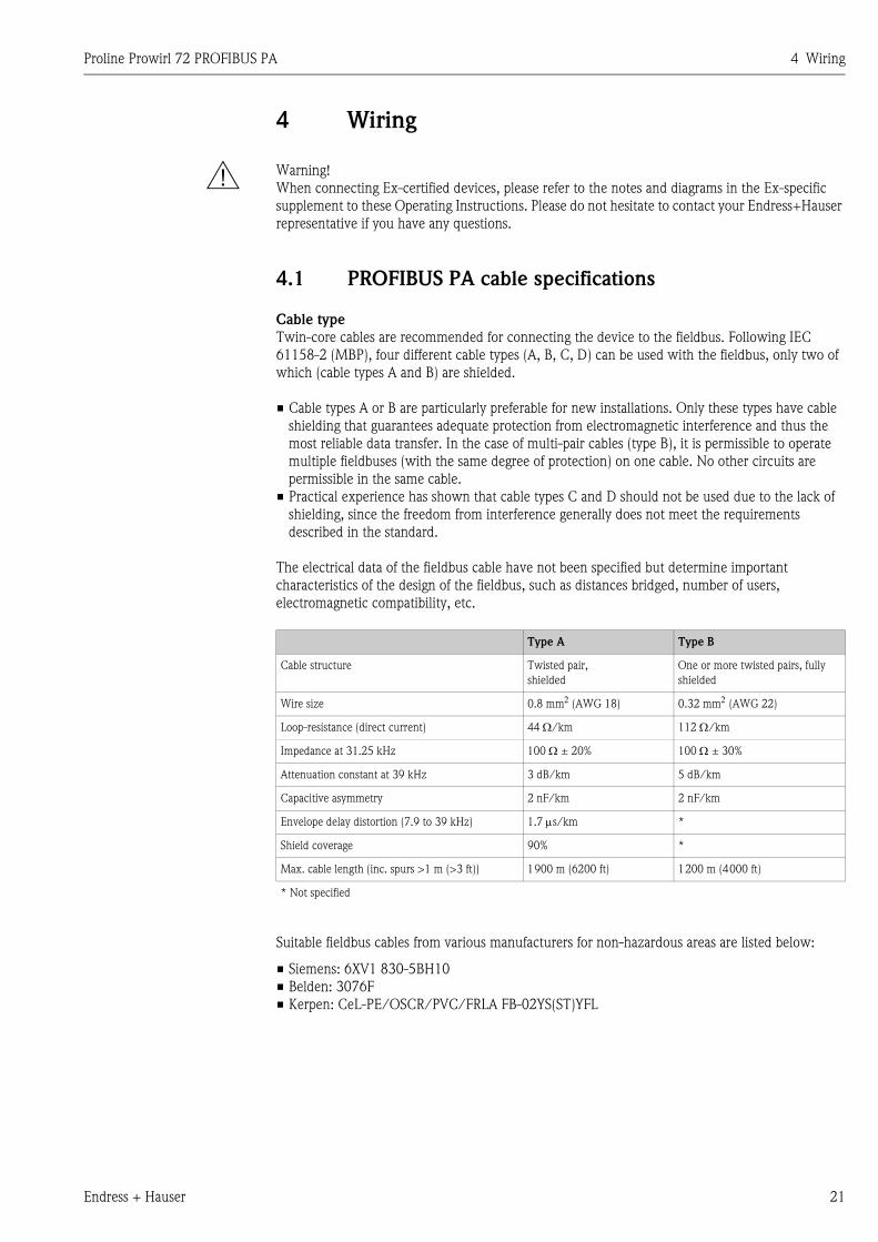
Cable type
Twin-core cables are recommended for connecting the device to the fieldbus. Following IEC
61158-2 (MBP), four different cable types (A, B, C, D) can be used with the fieldbus, only two of
which (cable types A and B) are shielded.
• Cable types A or B are particularly preferable for new installations. Only these types have cable
shielding that guarantees adequate protection from electromagnetic interference and thus the
most reliable data transfer. In the case of multi-pair cables (type B), it is permissible to operate
multiple fieldbuses (with the same degree of protection) on one cable. No other circuits are
permissible in the same cable.
• Practical experience has shown that cable types C and D should not be used due to the lack of
shielding, since the freedom from interference generally does not meet the requirements
described in the standard.
The electrical data of the fieldbus cable have not been specified but determine important
characteristics of the design of the fieldbus, such as distances bridged, number of users,
electromagnetic compatibility, etc.
Suitable fieldbus cables from various manufacturers for non-hazardous areas are listed below:
• Siemens: 6XV1 830-5BH10
• Belden: 3076F
• Kerpen: CeL-PE/OSCR/PVC/FRLA FB-02YS(ST)YFL
Type A Type B
Cable structure Twisted pair,
shielded
One or more twisted pairs, fully
shielded
Wire size 0.8 mm2 (AWG 18) 0.32 mm2 (AWG 22)
Loop-resistance (direct current) 44 Ω/km 112 Ω/km
Impedance at 31.25 kHz 100 Ω ± 20% 100 Ω ± 30%
Attenuation constant at 39 kHz 3 dB/km 5 dB/km
Capacitive asymmetry 2 nF/km 2 nF/km
Envelope delay distortion (7.9 to 39 kHz) 1.7 μs/km *
Shield coverage 90% *
Max. cable length (inc. spurs >1 m (>3 ft)) 1900 m (6200 ft) 1200 m (4000 ft)
* Not specified
4 Wiring Proline Prowirl 72 PROFIBUS PA
22 Endress + Hauser
Maximum overall cable length
The maximum network expansion depends on the type of protection and the cable specifications.
The overall cable length combines the length of the main cable and the length of all spurs (>1 m
(>3 ft)).
Note the following points:
• The maximum permissible overall cable length depends on the cable type used:
• If repeaters are used, the maximum permissible cable length is doubled.
A maximum of three repeaters are permitted between user and master.
Maximum spur length
The line between the distribution box and field device is described as a spur.
In the case of non-Ex applications, the max. length of a spur depends on the number of spurs (>1 m)
(>3 ft):
Number of field devices
In systems that meet FISCO in the EEx ia type of protection, the line length is limited to
max. 1000 m (3280 ft). A maximum of 32 users per segment in non-Ex areas or a maximum of
10 users in an Ex-area (EEx ia IIC) is possible. The actual number of users must be determined
during project planning.
Bus termination
The start and end of each fieldbus segment are always to be terminated with a bus terminator. With
various junction boxes (non-Ex), the bus termination can be activated via a switch. If this is not the
case, a separate bus terminator must be installed.
Note the following points:
• In the case of a branched bus segment, the device furthest from the segment coupler represents
the end of the bus.
• If the fieldbus is extended with a repeater then the extension must also be terminated at both
ends.
Further information
General information and further notes regarding the wiring can be found in the BA034S/04: "Field
communication PROFIBUS DP/PA: Guidelines for planning and commissioning".
Type A 1900 m 6200 ft
Type B 1200 m 4000 ft
Number of spurs 1 to 12 13 to 14 15 to 18 19 to 24 25 to 32
Max. length per spur[m] 120 90 60 30 1
[ft] 400 300 200 100 3
Proline Prowirl 72 PROFIBUS PA 4 Wiring
Endress + Hauser 23
4.1.1 Shielding and grounding
When planning the shielding and grounding for a fieldbus system, there are three important points
to consider:
• Electromagnetic compatibility (EMC)
• Explosion protection
• Safety of the personnel
To ensure the optimum electromagnetic compatibility of systems, it is important that the system
components and above all the cables, which connect the components, are shielded and that no
portion of the system is unshielded. Ideally, the cable shields will be connected to the field devices'
housings, which are usually metal. Since these are generally connected to the protective earth, the
shield of the bus cable is grounded many times. Make sure that the stripped and twisted lengths of
cable shield to the terminals are as short as possible.
This approach, which provides the best electromagnetic compatibility and personnel safety, can be
used without restriction in systems with good potential equalization.
In the case of systems without potential equalization, a power supply frequency (50 Hz) equalizing
current can flow between two grounding points which, in unfavorable cases, e.g. when it exceeds
the permissible shield current, may destroy the cable.
To suppress the low frequency equalizing currents on systems without potential equalization, it is
therefore recommended to connect the cable shield directly to the building ground (or protective
earth) at one end only and to use capacitive coupling to connect all other grounding points.
" Caution!
The legal EMC requirements are met only when the cable shield is grounded at both ends!.
4.2 Connecting the remote version
4.2.1 Connecting the sensor
! Note!
• The remote version must be grounded. In doing so, the sensor and transmitter must be connected
to the same potential matching.
• When using the remote version, always make sure that you connect the sensor only to the
transmitter with the same serial number. Compatibility errors (e.g. the incorrect K-factor will be
used) can occur if the devices are not connected in this way.
1. Remove the cover of the connection compartment of the transmitter (a).
2. Remove the cover of the connection compartment of the sensor (b).
3. Feed the connecting cable (c) through the appropriate cable entries.
4. Wire the connecting cable between the sensor and transmitter in accordance with the
electrical connection diagram:
→ Fig. 15
→ Wiring diagram in the screw caps
5. Tighten the glands of the cable entries on the sensor housing and transmitter housing.
6. Screw the cover of the connection compartment (a/b) back onto the sensor housing or
transmitter housing.
4 Wiring Proline Prowirl 72 PROFIBUS PA
24 Endress + Hauser
A0001893
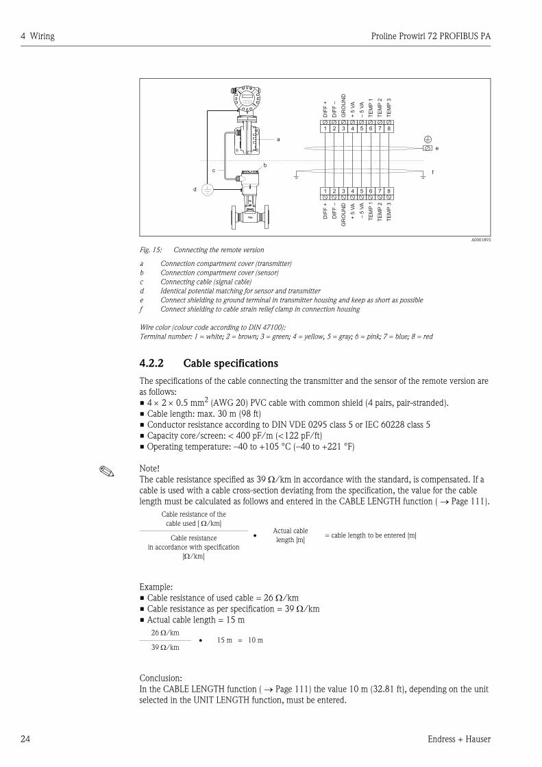
Fig. 15: Connecting the remote version
a Connection compartment cover (transmitter)
b Connection compartment cover (sensor)
c Connecting cable (signal cable)
d Identical potential matching for sensor and transmitter
e Connect shielding to ground terminal in transmitter housing and keep as short as possible
f Connect shielding to cable strain relief clamp in connection housing
Wire color (colour code according to DIN 47100):
Terminal number: 1 = white; 2 = brown; 3 = green; 4 = yellow, 5 = gray; 6 = pink; 7 = blue; 8 = red
4.2.2 Cable specifications
The specifications of the cable connecting the transmitter and the sensor of the remote version are
as follows:
• 4 × 2 × 0.5 mm2 (AWG 20) PVC cable with common shield (4 pairs, pair-stranded).
• Cable length: max. 30 m (98 ft)
• Conductor resistance according to DIN VDE 0295 class 5 or IEC 60228 class 5
• Capacity core/screen: < 400 pF/m (<122 pF/ft)
• Operating temperature: –40 to +105 °C (–40 to +221 °F)
! Note!
The cable resistance specified as 39 Ω/km in accordance with the standard, is compensated. If a
cable is used with a cable cross-section deviating from the specification, the value for the cable
length must be calculated as follows and entered in the CABLE LENGTH function ( → Page 111).
Example:
• Cable resistance of used cable = 26 Ω/km
• Cable resistance as per specification = 39 Ω/km
• Actual cable length = 15 m
Conclusion:
In the CABLE LENGTH function ( → Page 111) the value 10 m (32.81 ft), depending on the unit
selected in the UNIT LENGTH function, must be entered.
a
cb
d
3
3
1
1
4
4
2
2
5
5
6
6
7
7
8
8
DIF
F+
DIF
F+
DIF
F–
DIF
F–
GR
OU
ND
GR
OU
ND
+5
VA
+5
VA
–5
VA
–5
VA
TE
MP
1T
EM
P1
TE
MP
2T
EM
P2
TE
MP
3T
EM
P3
e
f
Cable resistance of the
cable used [ Ω/km]
•Actual cable
length [m]= cable length to be entered [m] Cable resistance
in accordance with specification
[Ω/km]
26 Ω/km• 15 m = 10 m
39 Ω/km
Proline Prowirl 72 PROFIBUS PA 4 Wiring
Endress + Hauser 25
4.3 Connecting the measuring unit
4.3.1 Connecting the transmitter
! Note!
• When connecting Ex-certified devices, please refer to the notes and diagrams in the Ex-specific
supplement to these Operating Instructions.
• The remote version must be grounded. In doing so, the sensor and transmitter must be connected
to the same potential equalization.
• The national regulations governing the installation of electrical equipment must be observed.
• When connecting the transmitter, use a connecting cable with a continuous service temperature
of at least –40 °C (–40 °F) to permitted max. ambient temperature plus 10 °C (plus 18 °F).
• A shielded cable must be used for the connection.
• The terminals for the PROFIBUS PA connection (terminal 1 = PA+, terminal 2 = PA –) have
integrated reverse polarity protection. This ensures correct signal transmission via the fieldbus
even if lines are confused.
• Cable cross-section: max. 2.5 mm²
• Observe the grounding concept.
" Caution!
• Risk of damaging the PROFIBUS cable!
If the shielding of the cable is grounded at more than one point in systems without additional
potential equalization, power supply frequency equalization currents can occur that damage the
cable or the shielding. In such cases the shielding of the cable is to be grounded on only one side,
i.e. it must not be connected to the ground terminal of the housing. The shield that is not
connected should be insulated!
• We recommend that the PROFIBUS not be looped using conventional cable glands. If you later
replace even just one measuring device, the bus communication will have to be interrupted.
4 Wiring Proline Prowirl 72 PROFIBUS PA
26 Endress + Hauser
Connecting the transmitter, non-Ex / Ex i/IS and Ex n version ( → Fig. 16)
1. Unscrew the cover (a) of the electronics compartment from the transmitter housing.
2. Remove the display module (b) from the retaining rails (c) and refit onto right retaining rail with
the left side (this secures the display module).
3. Loosen screw (d) of the cover of the connection compartment and fold down the cover.
4. Push the power supply/PROFIBUS cable through the cable gland (e).
5. Tighten the cable glands (e) (see also Page 30).
6. Pull the terminal connector (f) out of the transmitter housing and connect the power
supply/PROFIBUS cable ( → Fig. 18).
! Note!
The terminal connector (d) is pluggable, i.e. it can be plugged out of the transmitter housing
to connect the cable.
7. Plug the terminal connector (f) into the transmitter housing.
8. Secure the ground cable to the ground terminal (g).
! Note!
Between the stripped PROFIBUS cable and the ground terminal, the cable shielding should not
exceed a length of 5 mm (0.20 inch).
9. Only remote version:
Secure ground cable to the ground terminal ( → Fig. 18, B).
10. Fold up the cover of the connection compartment and tighten the screws (d).
11. Remove the display module (b) and fit on the retaining rails (c).
12. Screw the cover of the electronics compartment (a) onto the transmitter housing.
a0003782
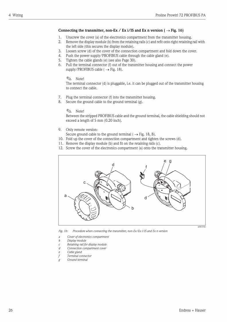
Fig. 16: Procedure when connecting the transmitter, non-Ex/Ex i/IS and Ex n version
a Cover of electronics compartment
b Display module
c Retaining rail for display module
d Connection compartment cover
e Cable gland
f Terminal connector
g Ground terminal
e
f
da
c
b
dg
Proline Prowirl 72 PROFIBUS PA 4 Wiring
Endress + Hauser 27
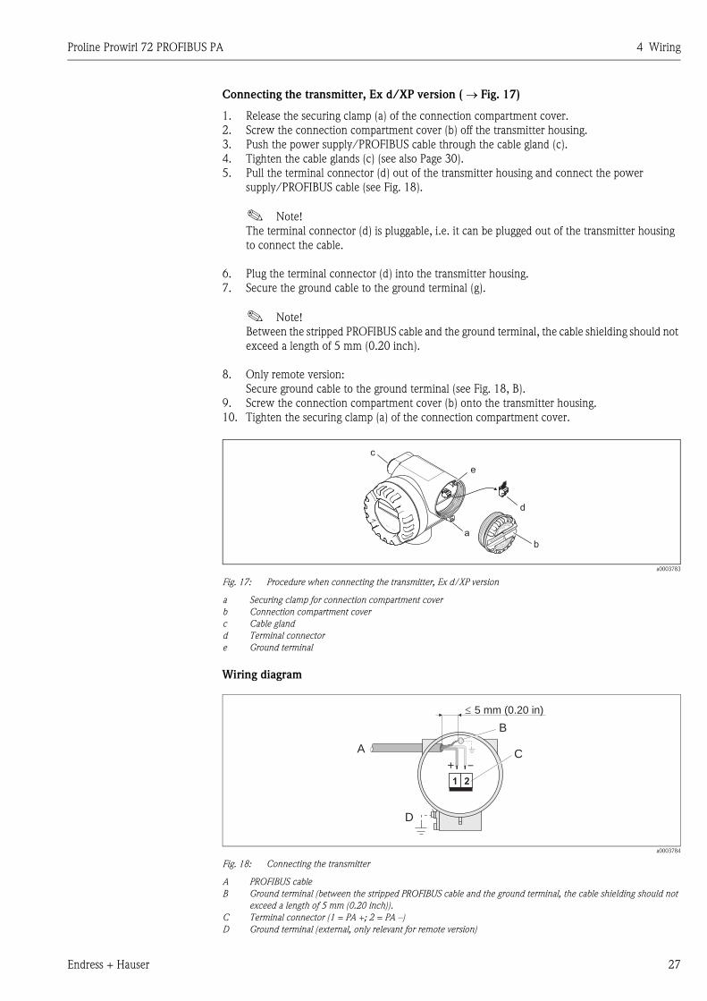
Connecting the transmitter, Ex d/XP version ( → Fig. 17)
1. Release the securing clamp (a) of the connection compartment cover.
2. Screw the connection compartment cover (b) off the transmitter housing.
3. Push the power supply/PROFIBUS cable through the cable gland (c).
4. Tighten the cable glands (c) (see also Page 30).
5. Pull the terminal connector (d) out of the transmitter housing and connect the power
supply/PROFIBUS cable (see Fig. 18).
! Note!
The terminal connector (d) is pluggable, i.e. it can be plugged out of the transmitter housing
to connect the cable.
6. Plug the terminal connector (d) into the transmitter housing.
7. Secure the ground cable to the ground terminal (g).
! Note!
Between the stripped PROFIBUS cable and the ground terminal, the cable shielding should not
exceed a length of 5 mm (0.20 inch).
8. Only remote version:
Secure ground cable to the ground terminal (see Fig. 18, B).
9. Screw the connection compartment cover (b) onto the transmitter housing.
10. Tighten the securing clamp (a) of the connection compartment cover.
a0003783
Fig. 17: Procedure when connecting the transmitter, Ex d/XP version
a Securing clamp for connection compartment cover
b Connection compartment cover
c Cable gland
d Terminal connector
e Ground terminal
Wiring diagram
a0003784
Fig. 18: Connecting the transmitter
A PROFIBUS cable
B Ground terminal (between the stripped PROFIBUS cable and the ground terminal, the cable shielding should not
exceed a length of 5 mm (0.20 inch)).
C Terminal connector (1 = PA +; 2 = PA –)
D Ground terminal (external, only relevant for remote version)
b
a
c
d
e
A
D
+ –
1 2
B
C
5 mm (0.20 in)
aaaaaaaaaaaaaaaaaaaaaaaaaaaaaaaaaaaaaaaaaaaaaaaaaaaaaaaaaaaaaaaaaaaaaaaaaaaaaaaaaaaaaaaaaaaaaaaaaaaaaaaaaaaaaaaaaaaaaaaaaaaaaaaaaaaaaaaaaaaaaaaaaaaaaaaaaaaaaaaaaaaaaaaaaaaaaaaaaaaaaaaaaaaaaaaaaaaaaaaaaaaaaaaaaaaaaaaaaaaaaaaaaaaaaaaaaaaaaaaaaaaaaaaaaaaaaaaaaaaaaaaaaaaaaaaaaaaaaaaaaaaaaaaaaaaaaaaaaaaaaaaaaaaaaaaaaaaaaaaaaaaaaaaaaaaaaaaaaaaaaaaaaaaaaaaaaaaaaaaaaaaaaaaaaaaaaaaaaaaaaaaaaaaaaaaaaaaaaaaaaaaaaaaaaaaaaaaaaaaaaaaaaaaaaaaaaaaaaaaaaaaaaaaaaaaaaaaaaaaaaaaaaaaaaaaaaaaaaaaaaaaaaaaaaaaaaaaaaaaaaaaa
�
4 Wiring Proline Prowirl 72 PROFIBUS PA
28 Endress + Hauser
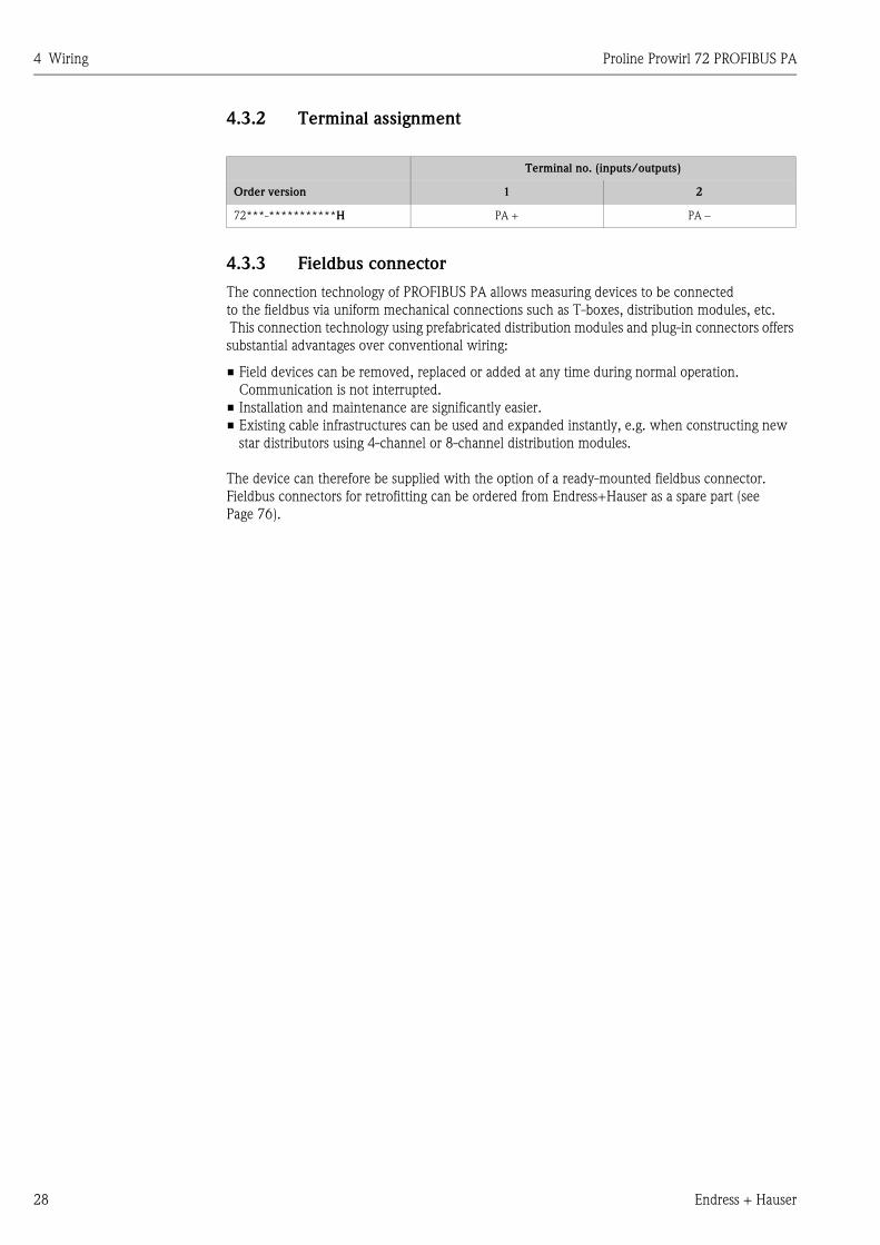
4.3.2 Terminal assignment
4.3.3 Fieldbus connector
The connection technology of PROFIBUS PA allows measuring devices to be connected
to the fieldbus via uniform mechanical connections such as T-boxes, distribution modules, etc.
This connection technology using prefabricated distribution modules and plug-in connectors offers
substantial advantages over conventional wiring:
• Field devices can be removed, replaced or added at any time during normal operation.
Communication is not interrupted.
• Installation and maintenance are significantly easier.
• Existing cable infrastructures can be used and expanded instantly, e.g. when constructing new
star distributors using 4-channel or 8-channel distribution modules.
The device can therefore be supplied with the option of a ready-mounted fieldbus connector.
Fieldbus connectors for retrofitting can be ordered from Endress+Hauser as a spare part (see
Page 76).
Terminal no. (inputs/outputs)
Order version 1 2
72***-***********H PA + PA –
Proline Prowirl 72 PROFIBUS PA 4 Wiring
Endress + Hauser 29
Supply line/T-box shielding
Use cable glands with good EMC properties, if possible with all-round contact of the cable shielding
(Iris spring). This requires small differences in potential, poss. potential equalization.
• The PA cable shielding must be intact.
• The shielding connection must always be kept as short as possible.
Ideally, cable glands with Iris springs should be used for the shielding connection. The shielding is
positioned on the T-box housing by means of the Iris spring located inside the gland. The shielding
braid is located beneath the Iris spring. When the armored thread is tightened, the Iris spring is
pressed against the shielding, thereby creating a conductive connection between the shielding and
the metal housing.
A connection box or a plug-in connection is to be seen as part of the shielding (Faraday shield). This
applies, in particular, to remote boxes if these are connected to a PROFIBUS PA measuring device
by means of a pluggable cable. In such instances, a metallic connector must be used where the cable
shielding is positioned at the plug housing (e.g. prefabricated cables).
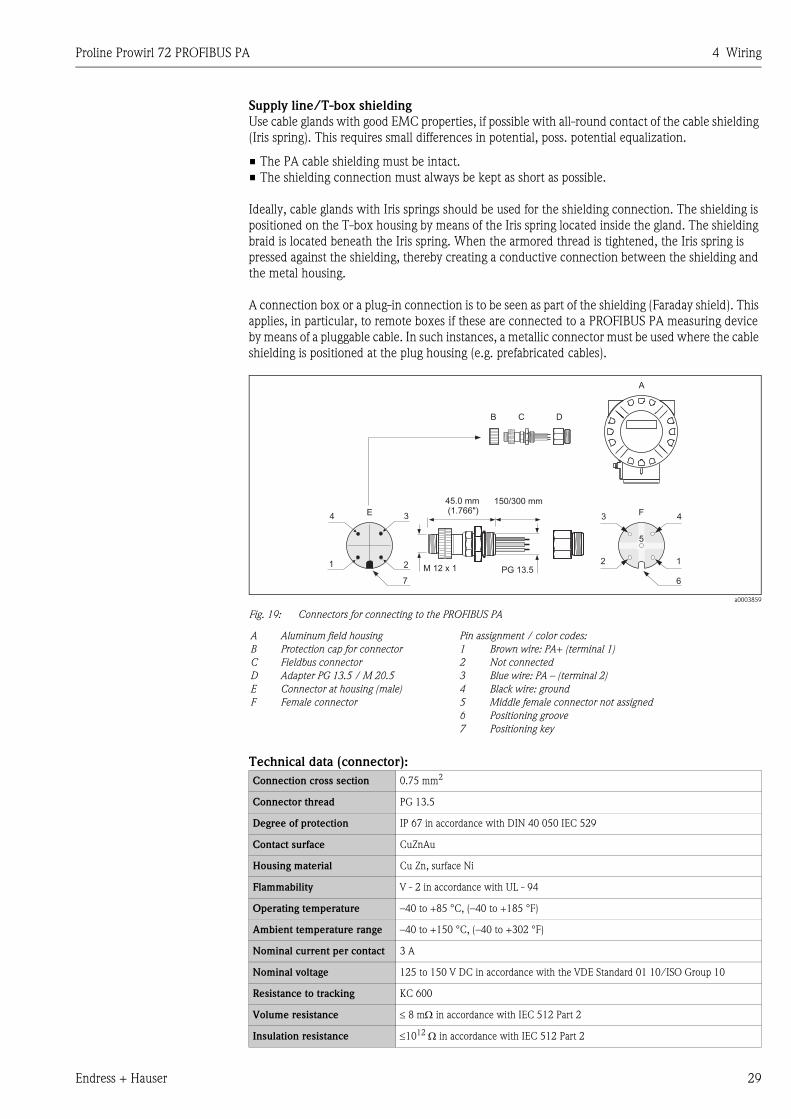
a0003859
Fig. 19: Connectors for connecting to the PROFIBUS PA
Technical data (connector):
A Aluminum field housing
B Protection cap for connector
C Fieldbus connector
D Adapter PG 13.5 / M 20.5
E Connector at housing (male)
F Female connector
Pin assignment / color codes:
1 Brown wire: PA+ (terminal 1)
2 Not connected
3 Blue wire: PA – (terminal 2)
4 Black wire: ground
5 Middle female connector not assigned
6 Positioning groove
7 Positioning key
Connection cross section 0.75 mm2
Connector thread PG 13.5
Degree of protection IP 67 in accordance with DIN 40 050 IEC 529
Contact surface CuZnAu
Housing material Cu Zn, surface Ni
Flammability V - 2 in accordance with UL - 94
Operating temperature –40 to +85 °C, (–40 to +185 °F)
Ambient temperature range –40 to +150 °C, (–40 to +302 °F)
Nominal current per contact 3 A
Nominal voltage 125 to 150 V DC in accordance with the VDE Standard 01 10/ISO Group 10
Resistance to tracking KC 600
Volume resistance ≤ 8 mΩ in accordance with IEC 512 Part 2
Insulation resistance ≤1012 Ω in accordance with IEC 512 Part 2
150/300 mm45.0 mm(1.766")
PG 13.5M 12 x 1
B C D
4
1 2
E 3 3 4
2 1
F
5
67
A
4 Wiring Proline Prowirl 72 PROFIBUS PA
30 Endress + Hauser
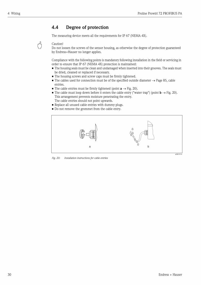
4.4 Degree of protection
The measuring device meets all the requirements for IP 67 (NEMA 4X).
" Caution!
Do not loosen the screws of the sensor housing, as otherwise the degree of protection guaranteed
by Endress+Hauser no longer applies.
Compliance with the following points is mandatory following installation in the field or servicing in
order to ensure that IP 67 (NEMA 4X) protection is maintained:
• The housing seals must be clean and undamaged when inserted into their grooves. The seals must
be dried, cleaned or replaced if necessary.
• The housing screws and screw caps must be firmly tightened.
• The cables used for connection must be of the specified outside diameter → Page 85, cable
entries.
• The cable entries must be firmly tightened (point a → Fig. 20).
• The cable must loop down before it enters the cable entry ("water trap") (point b → Fig. 20).
This arrangement prevents moisture penetrating the entry.
The cable entries should not point upwards.
• Replace all unused cable entries with dummy plugs.
• Do not remove the grommet from the cable entry.
a0001914
Fig. 20: Installation instructions for cable entries
a b
Proline Prowirl 72 PROFIBUS PA 4 Wiring
Endress + Hauser 31
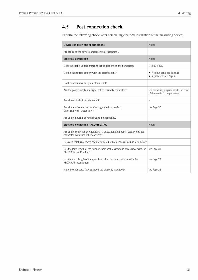
4.5 Post-connection check
Perform the following checks after completing electrical installation of the measuring device:
Device condition and specifications Notes
Are cables or the device damaged (visual inspection)? −
Electrical connection Notes
Does the supply voltage match the specifications on the nameplate? 9 to 32 V DC
Do the cables used comply with the specifications? • Fieldbus cable see Page 21
• Signal cable see Page 21
Do the cables have adequate strain relief? −
Are the power supply and signal cables correctly connected? See the wiring diagram inside the cover
of the terminal compartment
Are all terminals firmly tightened? −
Are all the cable entries installed, tightened and sealed?
Cable run with "water trap"?
see Page 30
Are all the housing covers installed and tightened? −
Electrical connection - PROFIBUS PA Notes
Are all the connecting components (T-boxes, junction boxes, connectors, etc.)
connected with each other correctly?
–
Has each fieldbus segment been terminated at both ends with a bus terminator? –
Has the max. length of the fieldbus cable been observed in accordance with the
PROFIBUS specifications?
see Page 21
Has the max. length of the spurs been observed in accordance with the
PROFIBUS specifications?
see Page 22
Is the fieldbus cable fully shielded and correctly grounded? see Page 22

4 Wiring Proline Prowirl 72 PROFIBUS PA
32 Endress + Hauser
Proline Prowirl 72 PROFIBUS PA 5 Operation
Endress + Hauser 33
5 Operation
5.1 Quick operation guide
You have a number of options for configuring and commissioning the device:
1. Configuration programs → Page 36
The configuration of profile and device-specific parameters is primarily done via the PROFIBUS PA
interface. You can obtain special configuration and operating programs from various manufacturers
for these purposes.
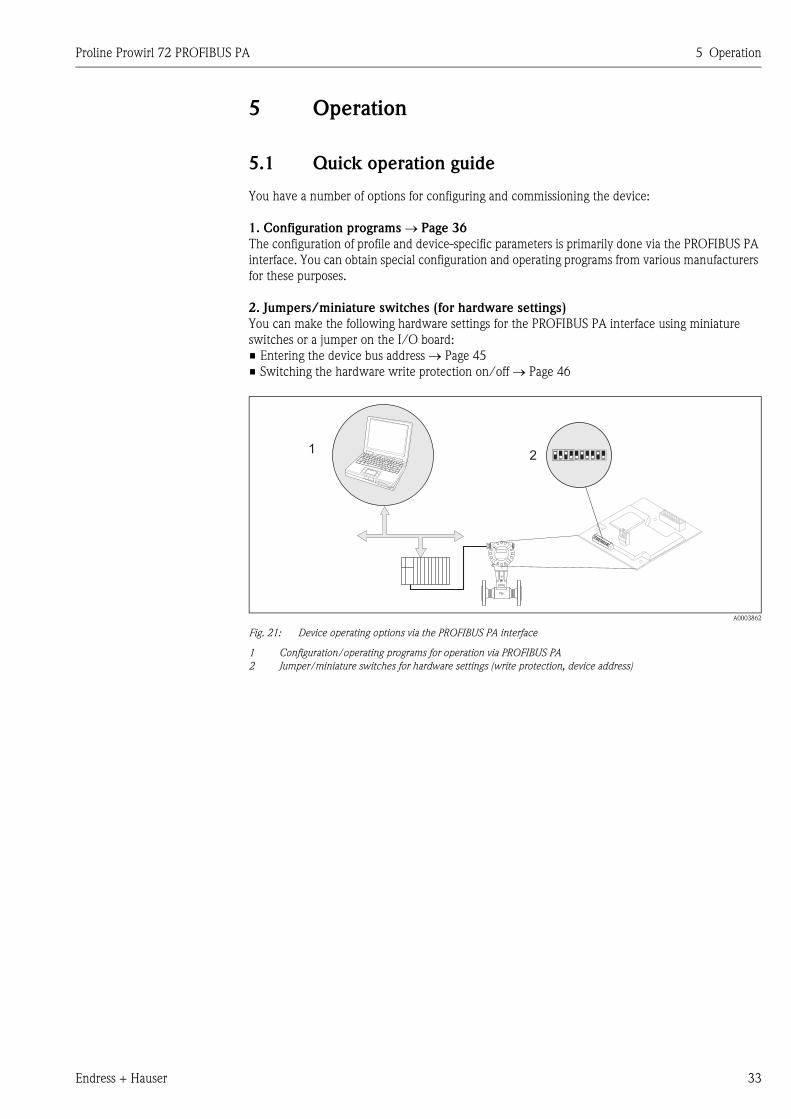
2. Jumpers/miniature switches (for hardware settings)
You can make the following hardware settings for the PROFIBUS PA interface using miniature
switches or a jumper on the I/O board:
• Entering the device bus address → Page 45
• Switching the hardware write protection on/off → Page 46
A0003862
Fig. 21: Device operating options via the PROFIBUS PA interface
1 Configuration/operating programs for operation via PROFIBUS PA
2 Jumper/miniature switches for hardware settings (write protection, device address)
12
Esc
E- +
5 Operation Proline Prowirl 72 PROFIBUS PA
34 Endress + Hauser
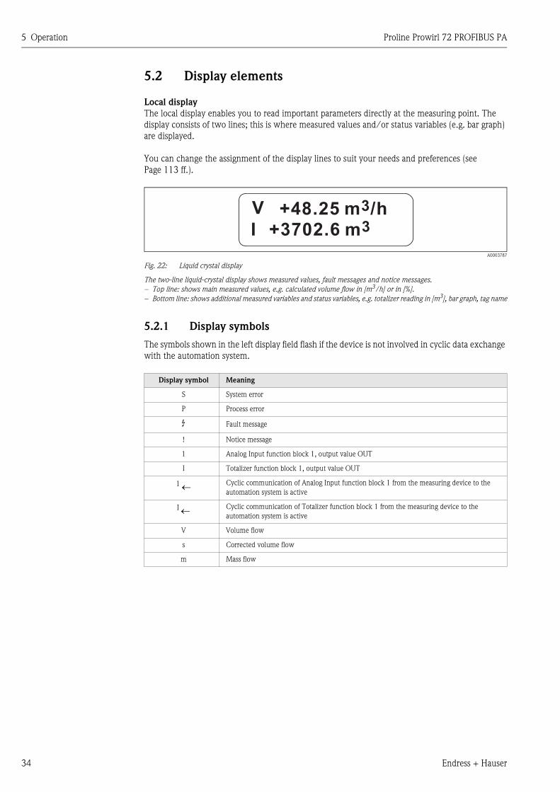
5.2 Display elements
Local display
The local display enables you to read important parameters directly at the measuring point. The
display consists of two lines; this is where measured values and/or status variables (e.g. bar graph)
are displayed.
You can change the assignment of the display lines to suit your needs and preferences (see
Page 113 ff.).
A0003787
Fig. 22: Liquid crystal display
The two-line liquid-crystal display shows measured values, fault messages and notice messages.
– Top line: shows main measured values, e.g. calculated volume flow in [m3/h] or in [%].
– Bottom line: shows additional measured variables and status variables, e.g. totalizer reading in [m3], bar graph, tag name
5.2.1 Display symbols
The symbols shown in the left display field flash if the device is not involved in cyclic data exchange
with the automation system.
Display symbol Meaning
S System error
P Process error
$ Fault message
! Notice message
1 Analog Input function block 1, output value OUT
I Totalizer function block 1, output value OUT
1 ← Cyclic communication of Analog Input function block 1 from the measuring device to the
automation system is active
I ← Cyclic communication of Totalizer function block 1 from the measuring device to the
automation system is active
V Volume flow
s Corrected volume flow
m Mass flow
+48.25 m /h3
+3702.6 m3I
V
Proline Prowirl 72 PROFIBUS PA 5 Operation
Endress + Hauser 35
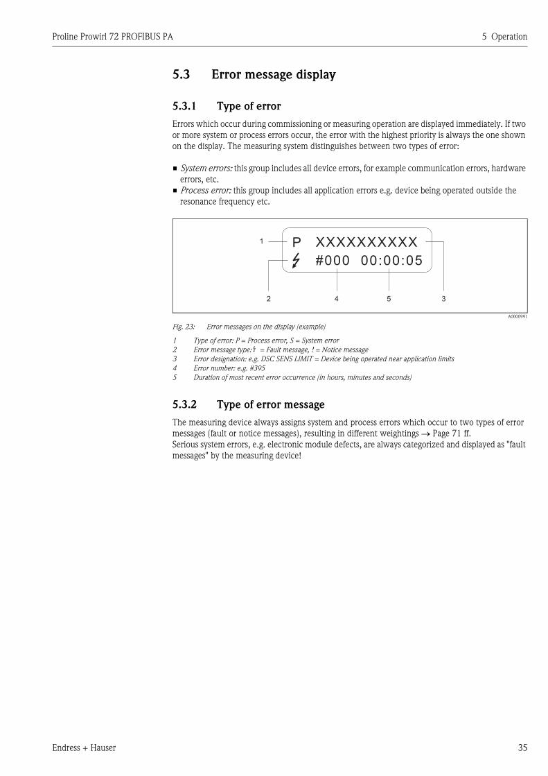
5.3 Error message display
5.3.1 Type of error
Errors which occur during commissioning or measuring operation are displayed immediately. If two
or more system or process errors occur, the error with the highest priority is always the one shown
on the display. The measuring system distinguishes between two types of error:
• System errors: this group includes all device errors, for example communication errors, hardware
errors, etc.
• Process error: this group includes all application errors e.g. device being operated outside the
resonance frequency etc.
A0000991
Fig. 23: Error messages on the display (example)
1 Type of error: P = Process error, S = System error
2 Error message type: $ = Fault message, ! = Notice message
3 Error designation: e.g. DSC SENS LIMIT = Device being operated near application limits
4 Error number: e.g. #395
5 Duration of most recent error occurrence (in hours, minutes and seconds)
5.3.2 Type of error message
The measuring device always assigns system and process errors which occur to two types of error
messages (fault or notice messages), resulting in different weightings → Page 71 ff.
Serious system errors, e.g. electronic module defects, are always categorized and displayed as "fault
messages" by the measuring device!
1
2 4 5 3
XXXXXXXXXX
#000 00:00:05
P
5 Operation Proline Prowirl 72 PROFIBUS PA
36 Endress + Hauser
5.4 Operating options
5.4.1 Operating program "ToF Tool Fieldtool Package"
Modular software package consisting of the "ToF Tool" service program for the configuration and
diagnosis of ToF level measuring devices (time-of-flight measurement) and the "Fieldtool" service
program for the configuration and diagnosis of Proline flowmeters. The Proline flowmeters are
accessed via a service interface or the FXA 193 service interface.
Contents of the "ToF Tool - Fieldtool Package":
• Commissioning, maintenance analysis
• Measuring device configuration
• Service functions
• Visualization of process data
• Troubleshooting
• Access to the verification data and updating the software of the "Fieldcheck" flow simulator
Program download: www.ToF-Fieldtool.endress.com
5.4.2 Operating program "FieldCare"
FieldCare is Endress+Hauser’s FDT-based plant asset management tool and allows the configuration
and diagnosis of intelligent field devices. By using status information, you also have a simple and
effective tool for monitoring devices. The Proline flowmeters are accessed via a service interface or
the FXA 193 service interface.
For further information, visit www.endress.com
5.4.3 Operating program "SIMATIC PDM" (Siemens)
SIMATIC PDM is a vendor-independent tool for operating, configuring, maintaining and diagnosing
intelligent field devices.
For further information, visit www.endress.com
Proline Prowirl 72 PROFIBUS PA 5 Operation
Endress + Hauser 37
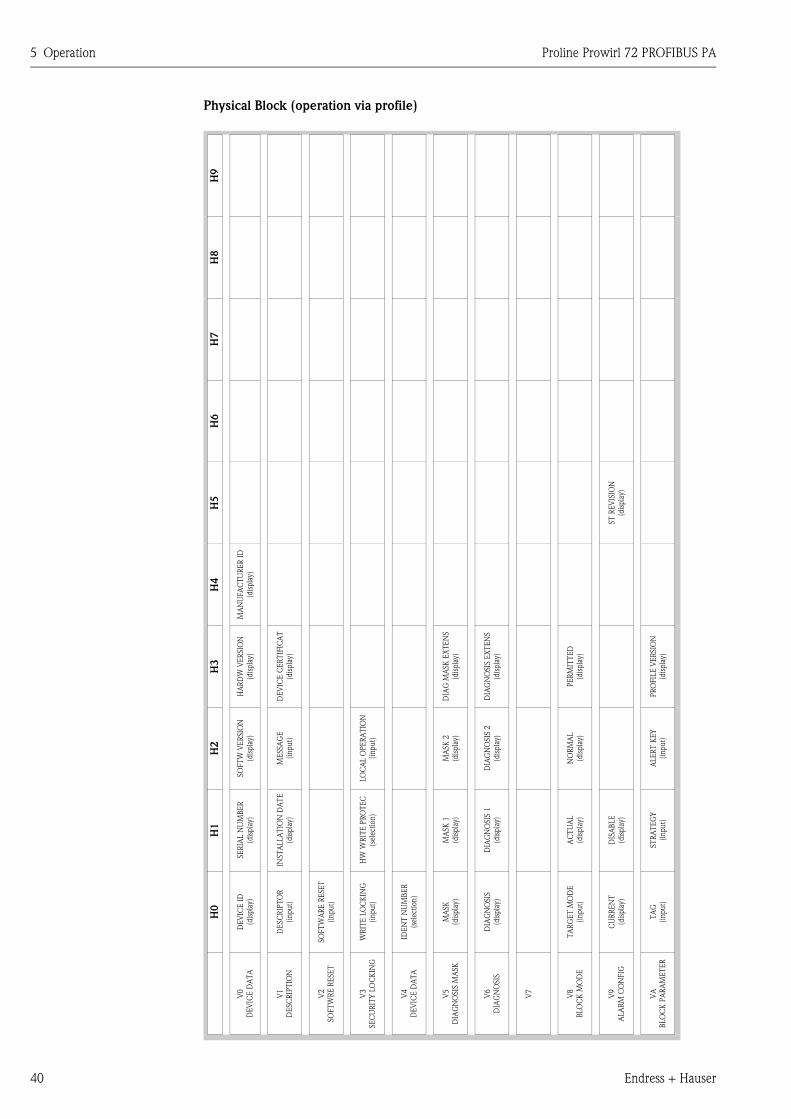
5.4.4 Commuwin II operating program
Commuwin II is a program for remote operation of field and control-room equipment. Commuwin
II can be used irrespective of the device type and the mode of communication (HART or
PROFIBUS).
! Note!
You can find more information on the Commuwin II operating program in the following
Endress+Hauser documents:
• System Information: SI 018F/00/en "Commuwin II"
• Operating Instructions: BA 124F/00/en "Commuwin II"- operating program
• An exact description of the data types can be found in the slot/index lists on Page 162 ff.
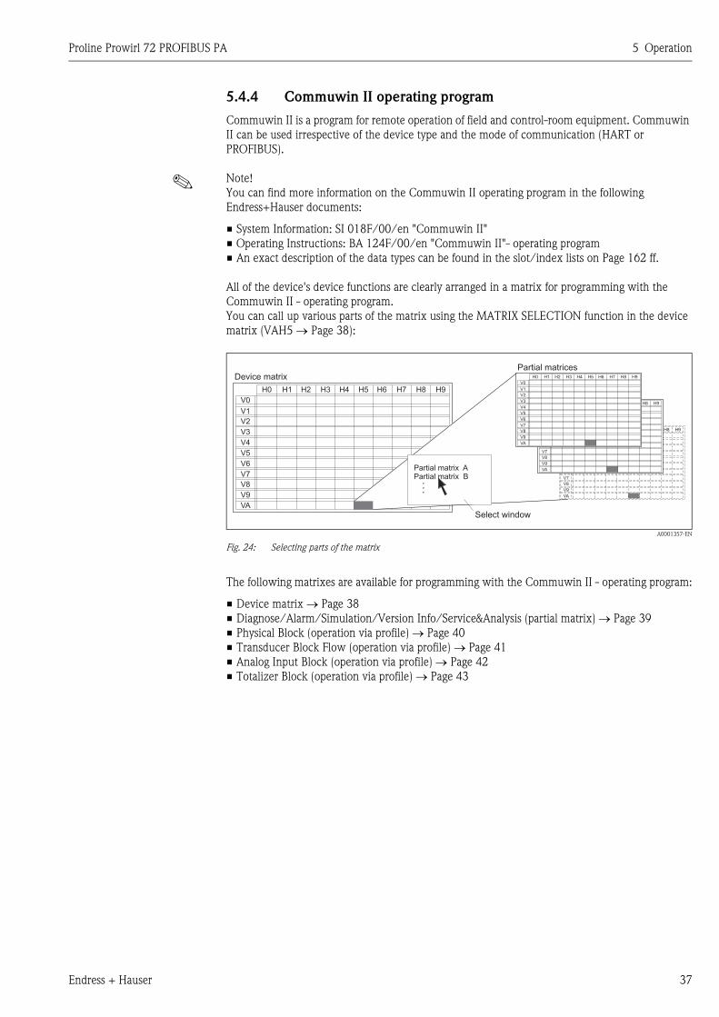
All of the device's device functions are clearly arranged in a matrix for programming with the
Commuwin II - operating program.
You can call up various parts of the matrix using the MATRIX SELECTION function in the device
matrix (VAH5 → Page 38):
A0001357-EN
Fig. 24: Selecting parts of the matrix
The following matrixes are available for programming with the Commuwin II - operating program:
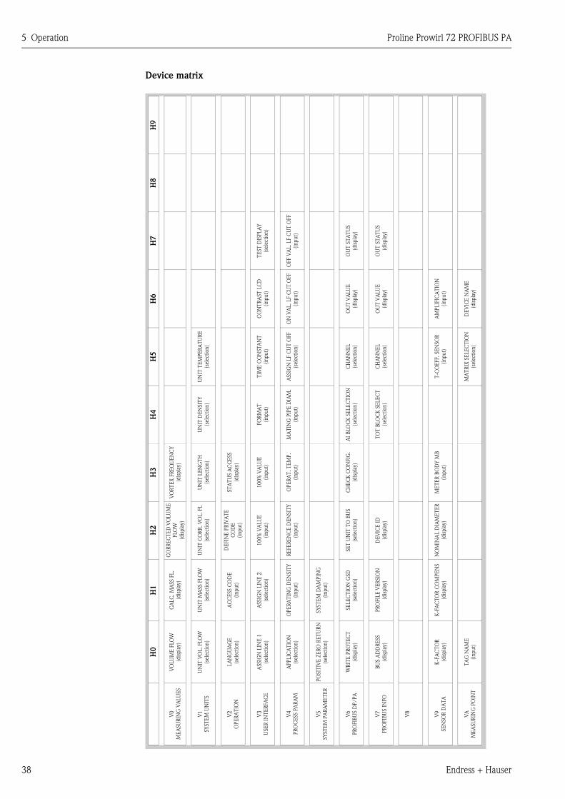
• Device matrix → Page 38
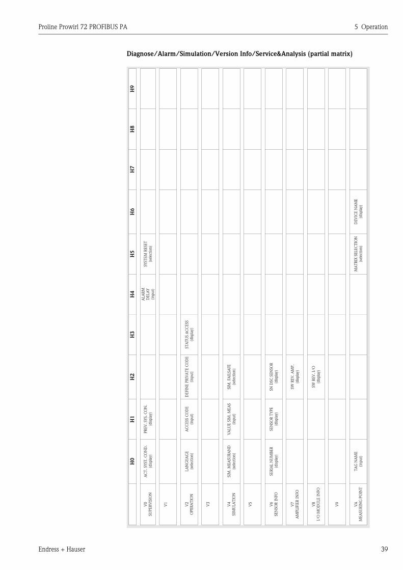
• Diagnose/Alarm/Simulation/Version Info/Service&Analysis (partial matrix) → Page 39
• Physical Block (operation via profile) → Page 40
• Transducer Block Flow (operation via profile) → Page 41
• Analog Input Block (operation via profile) → Page 42
• Totalizer Block (operation via profile) → Page 43
H0 H1 H2 H3 H4 H5 H6 H7 H8 H9
V0
V1
V2
V3
V4
V5
V6
V7
V8
V9
VA
H0 H1 H2 H3 H4 H5 H6 H7 H8 H9
V0
V1
V2
V3
V4
V5
V6
V7
V8
V9
VA
H0 H1 H2 H3 H4 H5 H6 H7 H8 H9
V0
V1
V2
V3
V4
V5
V6
V7
V8
V9
VA
H0 H1 H2 H3 H4 H5 H6 H7 H8 H9
V0
V1
V2
V3
V4
V5
V6
V7
V8
V9
VA
Partial matrix APartial matrix B
Device matrixPartial matrices
Select window
5 Operation Proline Prowirl 72 PROFIBUS PA
38 Endress + Hauser
Device matrix
H9
H8
H7
TE
ST
DIS
PLA
Y
(sel
ecti
on
)
OFF V
AL. LF C
UT
OFF
(in
pu
t)
OU
T S
TA
TU
S
(dis
pla
y)
OU
T S
TA
TU
S
(dis
pla
y)
H6
CO
NT
RA
ST
LC
D
(in
pu
t)
ON
VA
L. LF C
UT
OFF
(in
pu
t)
OU
T V
ALU
E
(dis
pla
y)
OU
T V
ALU
E
(dis
pla
y)
AM
PLIF
ICA
TIO
N
(in
pu
t)
DE
VIC
E N
AM
E
(dis
pla
y)
H5
UN
IT T
EM
PE
RA
TU
RE
(sel
ecti
on
)
TIM
E C
ON
ST
AN
T
(in
pu
t)
ASSIG
N L
F C
UT
OFF
(sel
ecti
on
)
CH
AN
NE
L
(sel
ecti
on
)
CH
AN
NE
L
(sel
ecti
on
)
T-C
OE
FF. SE
NSO
R
(in
pu
t)
MA
TR
IX S
ELE
CT
ION
(sel
ecti
on
)
H4
UN
IT D
EN
SIT
Y
(sel
ecti
on
)
FO
RM
AT
(in
pu
t)
MA
TIN
G P
IPE
DIA
M.
(in
pu
t)
AI
BLO
CK
SE
LE
CT
ION
(sel
ecti
on
)
TO
T B
LO
CK
SE
LE
CT
(sel
ecti
on
)
H3
VO
RT
EX
FR
EQ
UE
NC
Y
(dis
pla
y)
UN
IT L
EN
GT
H
(sel
ecti
on
)
ST
AT
US A
CC
ESS
(dis
pla
y)
10
0%
VA
LU
E
(in
pu
t)
OP
ER
AT
. T
EM
P.
(in
pu
t)
CH
EC
K C
ON
FIG
.
(dis
pla
y)
ME
TE
R B
OD
Y M
B
(in
pu
t)
H2
CO
RR
EC
TE
D V
OLU
ME
FLO
W
(dis
pla
y)
UN
IT C
OR
R.
VO
L.
FL
(sel
ecti
on)
DE
FIN
E P
RIV
AT
E
CO
DE
(in
pu
t)
100%
VA
LU
E
(in
pu
t)
RE
FE
RE
NC
E D
EN
SIT
Y
(in
pu
t)
SE
T U
NIT
TO
BU
S
(sel
ecti
on)
DE
VIC
E I
D
(dis
pla
y)
NO
MIN
AL D
IAM
ET
ER
(dis
pla
y)
H1
CA
LC
. M
ASS F
L.
(dis
pla
y)
UN
IT M
ASS F
LO
W
(sel
ecti
on
)
AC
CE
SS C
OD
E
(in
pu
t)
ASSIG
N L
INE
2
(sel
ecti
on
)
OPE
RA
TIN
G D
EN
SIT
Y
(in
pu
t)
SY
ST
EM
DA
MPIN
G
(in
pu
t)
SE
LE
CT
ION
GSD
(sel
ecti
on
)
PR
OFIL
E V
ER
SIO
N
(dis
pla
y)
K-F
AC
TO
R C
OM
PE
NS
(dis
pla
y)
H0
VO
LU
ME
FLO
W
(dis
pla
y)
UN
IT V
OL. FLO
W
(sel
ecti
on)
LA
NG
UA
GE
(sel
ecti
on)
ASSIG
N L
INE
1
(sel
ecti
on)
APPLIC
AT
ION
(sel
ecti
on)
PO
SIT
IVE
ZE
RO
RE
TU
RN
(sel
ecti
on)
WR
ITE
PR
OT
EC
T
(dis
pla
y)
BU
S A
DD
RE
SS
(dis
pla
y)
K-F
AC
TO
R
(dis
pla
y)
TA
G N
AM
E
(inpu
t)
V0
ME
ASU
RIN
G V
ALU
ES
V1
SY
ST
EM
UN
ITS
V2
OPE
RA
TIO
N
V3
USE
R I
NT
ER
FA
CE
V4
PR
OC
ESS P
AR
AM
V5
SY
ST
EM
PA
RA
ME
TE
R
V6
PR
OFIB
US D
P/PA
V7
PR
OFIB
US I
NFO
V8
V9
SE
NSO
R D
AT
A
VA
ME
ASU
RIN
G P
OIN
T
Proline Prowirl 72 PROFIBUS PA 5 Operation
Endress + Hauser 39
Diagnose/Alarm/Simulation/Version Info/Service&Analysis (partial matrix)
H9
H8
H7
H6
DE
VIC
E N
AM
E
(dis
pla
y)
H5
SY
ST
EM
RE
SE
T
(sel
ecti
on)
MA
TR
IX S
ELE
CT
ION
(sel
ecti
on)
H4
ALA
RM
DE
LA
Y
(in
pu
t)
H3
ST
AT
US A
CC
ESS
(dis
pla
y)
H2
DE
FIN
E P
RIV
AT
E C
OD
E
(in
pu
t)
SIM
. FA
ILSA
FE
(sel
ecti
on
)
SN
DSC
SE
NSO
R
(dis
pla
y)
SW
RE
V. A
MP.
(dis
pla
y)
SW
RE
V. I/
O
(dis
pla
y)
H1
PR
EV
. SY
S. C
ON
.
(dis
pla
y)
AC
CE
SS C
OD
E
(in
pu
t)
VA
LU
E S
IM.
ME
AS
(in
pu
t)
SE
NSO
R T
YPE
(dis
pla
y)
H0
AC
T. SY
ST
. C
ON
D.
(dis
pla
y)
LA
NG
UA
GE
(sel
ecti
on
)
SIM
. M
EA
SU
RA
ND
(sel
ecti
on
)
SE
RIA
L N
UM
BE
R
(dis
pla
y)
TA
G N
AM
E
(in
pu
t)
V0
SU
PE
RV
ISIO
N
V1
V2
OPE
RA
TIO
N
V3
V4
SIM
ULA
TIO
N
V5
V6
SE
NSO
R I
NFO
V7
AM
PLIF
IER
IN
FO
V8
I/O
MO
DU
LE
IN
FO
V9
VA
ME
ASU
RIN
G P
OIN
T
5 Operation Proline Prowirl 72 PROFIBUS PA
40 Endress + Hauser
Physical Block (operation via profile)
H9
H8
H7
H6
H5
ST
RE
VIS
ION
(dis
pla
y)
H4
MA
NU
FA
CT
UR
ER
ID
(dis
pla
y)
H3
HA
RD
W V
ER
SIO
N
(dis
pla
y)
DE
VIC
E C
ER
TIF
ICA
T
(dis
pla
y)
DIA
G M
ASK
EX
TE
NS
(dis
pla
y)
DIA
GN
OSIS
EX
TE
NS
(dis
pla
y)
PE
RM
ITT
ED
(dis
pla
y)
PR
OFIL
E V
ER
SIO
N
(dis
pla
y)
H2
SO
FT
W V
ER
SIO
N
(dis
pla
y)
ME
SSA
GE
(in
pu
t)
LO
CA
L O
PE
RA
TIO
N
(in
pu
t)
MA
SK
2
(dis
pla
y)
DIA
GN
OSIS
2
(dis
pla
y)
NO
RM
AL
(dis
pla
y)
ALE
RT
KE
Y
(in
pu
t)
H1
SE
RIA
L N
UM
BE
R
(dis
pla
y)
INST
ALLA
TIO
N D
AT
E
(dis
pla
y)
HW
WR
ITE
PR
OT
EC
(sel
ecti
on
)
MA
SK
1
(dis
pla
y)
DIA
GN
OSIS
1
(dis
pla
y)
AC
TU
AL
(dis
pla
y)
DIS
AB
LE
(dis
pla
y)
ST
RA
TE
GY
(in
pu
t)
H0
DE
VIC
E I
D
(dis
pla
y)
DE
SC
RIP
TO
R
(in
pu
t)
SO
FT
WA
RE
RE
SE
T
(in
pu
t)
WR
ITE
LO
CK
ING
(in
pu
t)
IDE
NT
NU
MB
ER
(sel
ecti
on
)
MA
SK
(dis
pla
y)
DIA
GN
OSIS
(dis
pla
y)
TA
RG
ET
MO
DE
(in
pu
t)
CU
RR
EN
T
(dis
pla
y)
TA
G
(in
pu
t)
V0
DE
VIC
E D
AT
A
V1
DE
SC
RIP
TIO
N
V2
SO
FT
WR
E R
ESE
T
V3
SE
CU
RIT
Y L
OC
KIN
G
V4
DE
VIC
E D
AT
A
V5
DIA
GN
OSIS
MA
SK
V6
DIA
GN
OSIS
V7
V8
BLO
CK
MO
DE
V9
ALA
RM
CO
NFIG
VA
BLO
CK
PA
RA
ME
TE
R
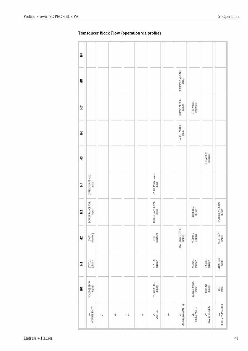
Proline Prowirl 72 PROFIBUS PA 5 Operation
Endress + Hauser 41
Transducer Block Flow (operation via profile)
H9
H8
NO
MIN
AL S
IZE
UN
IT
(in
pu
t)
H7
NO
MIN
AL S
IZE
(in
pu
t)
UN
IT M
OD
E
(sel
ecti
on
)
H6
CA
LIB
. FA
CT
OR
(in
pu
t)
H5
ST
RE
VIS
ION
(dis
pla
y)
H4
UP
PE
R R
AN
GE
VA
L.
(in
pu
t)
UP
PE
R R
AN
GE
VA
L.
(in
pu
t)
H3
LO
WE
R R
AN
GE
VA
L.
(in
pu
t)
LO
WE
R R
AN
GE
VA
L.
(in
pu
t)
PE
RM
ITT
ED
(dis
pla
y)
PR
OFIL
E V
ER
SIO
N
(dis
pla
y)
H2
UN
IT
(sel
ecti
on
)
UN
IT
(sel
ecti
on
)
LO
W F
LO
W C
UT
OFF
(in
pu
t)
NO
RM
AL
(dis
pla
y)
ALE
RT
KE
Y
(in
pu
t)
H1
ST
AT
US
(dis
pla
y)
ST
AT
US
(dis
pla
y)
AC
TU
AL
(dis
pla
y)
DIS
AB
LE
(dis
pla
y)
ST
RA
TE
GY
(in
pu
t)
H0
VO
LU
ME
FLO
W
(dis
pla
y)
VO
RT
EX
FR
EQ
(dis
pla
y)
TA
RG
ET
MO
DE
(in
pu
t)
CU
RR
EN
T
(dis
pla
y)
TA
G
(in
pu
t)
V0
VO
LU
ME
FLO
W
V1
V2
V3
V4
V5
VO
RT
EX
V6
V7
SY
ST
EM
PA
RA
ME
TE
R
V8
BLO
CK
MO
DE
V9
ALA
RM
CO
NFIG
VA
BLO
CK
PA
RA
ME
TE
R
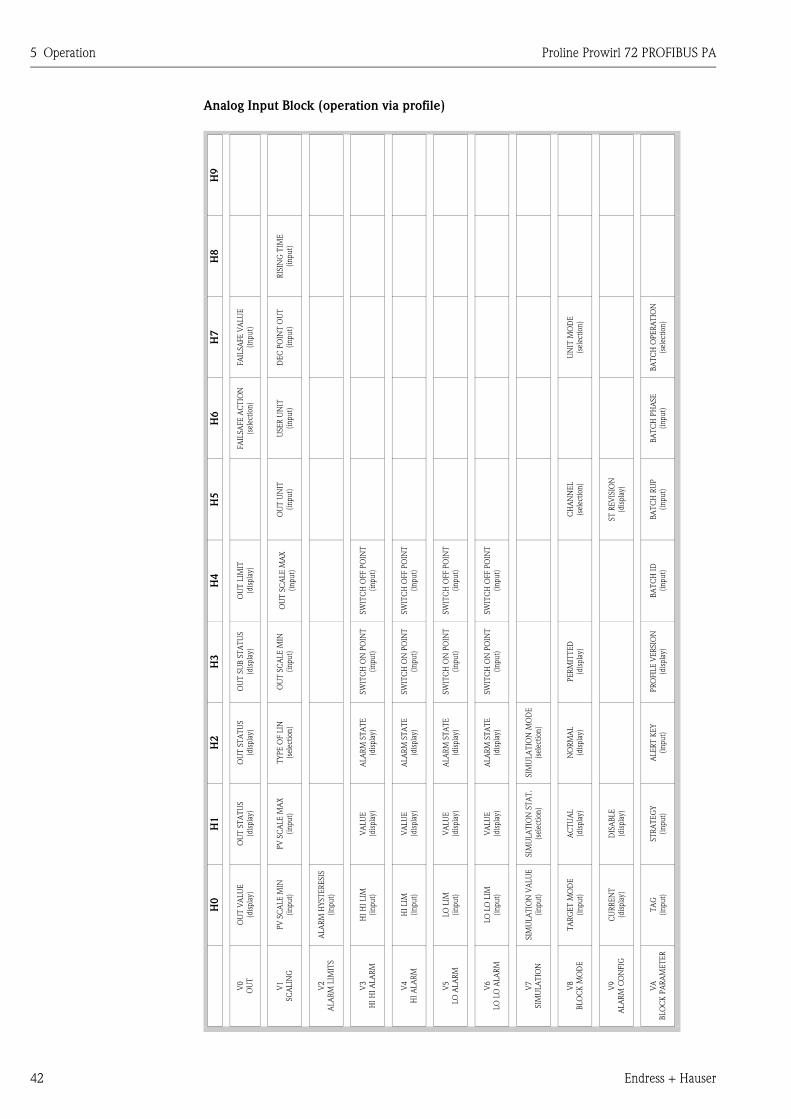
5 Operation Proline Prowirl 72 PROFIBUS PA
42 Endress + Hauser
Analog Input Block (operation via profile)
H9
H8
RIS
ING
TIM
E
(in
pu
t)
H7
FA
ILSA
FE
VA
LU
E
(in
pu
t)
DE
C P
OIN
T O
UT
(in
pu
t)
UN
IT M
OD
E
(sel
ecti
on
)
BA
TC
H O
PE
RA
TIO
N
(sel
ecti
on
)
H6
FA
ILSA
FE
AC
TIO
N
(sel
ecti
on)
USE
R U
NIT
(in
pu
t)
BA
TC
H P
HA
SE
(in
pu
t)
H5
OU
T U
NIT
(in
pu
t)
CH
AN
NE
L
(sel
ecti
on
)
ST
RE
VIS
ION
(dis
pla
y)
BA
TC
H R
UP
(in
pu
t)
H4
OU
T L
IMIT
(dis
pla
y)
OU
T S
CA
LE
MA
X
(in
pu
t)
SW
ITC
H O
FF P
OIN
T
(in
pu
t)
SW
ITC
H O
FF P
OIN
T
(in
pu
t)
SW
ITC
H O
FF P
OIN
T
(in
pu
t)
SW
ITC
H O
FF P
OIN
T
(in
pu
t)
BA
TC
H I
D
(in
pu
t)
H3
OU
T S
UB
ST
AT
US
(dis
pla
y)
OU
T S
CA
LE
MIN
(in
pu
t)
SW
ITC
H O
N P
OIN
T
(in
pu
t)
SW
ITC
H O
N P
OIN
T
(in
pu
t)
SW
ITC
H O
N P
OIN
T
(in
pu
t)
SW
ITC
H O
N P
OIN
T
(in
pu
t)
PE
RM
ITT
ED
(dis
pla
y)
PR
OFIL
E V
ER
SIO
N
(dis
pla
y)
H2
OU
T S
TA
TU
S
(dis
pla
y)
TY
PE
OF L
IN
(sel
ecti
on)
ALA
RM
ST
AT
E
(dis
pla
y)
ALA
RM
ST
AT
E
(dis
pla
y)
ALA
RM
ST
AT
E
(dis
pla
y)
ALA
RM
ST
AT
E
(dis
pla
y)
SIM
ULA
TIO
N M
OD
E
(sel
ecti
on)
NO
RM
AL
(dis
pla
y)
ALE
RT
KE
Y
(input)
H1
OU
T S
TA
TU
S
(dis
pla
y)
PV
SC
ALE
MA
X
(in
pu
t)
VA
LU
E
(dis
pla
y)
VA
LU
E
(dis
pla
y)
VA
LU
E
(dis
pla
y)
VA
LU
E
(dis
pla
y)
SIM
ULA
TIO
N S
TA
T.
(sel
ecti
on)
AC
TU
AL
(dis
pla
y)
DIS
AB
LE
(dis
pla
y)
ST
RA
TE
GY
(in
pu
t)
H0
OU
T V
ALU
E
(dis
pla
y)
PV
SC
ALE
MIN
(in
pu
t)
ALA
RM
HY
ST
ER
ESIS
(in
pu
t)
HI
HI
LIM
(in
pu
t)
HI
LIM
(in
pu
t)
LO
LIM
(in
pu
t)
LO
LO
LIM
(in
pu
t)
SIM
ULA
TIO
N V
ALU
E
(in
pu
t)
TA
RG
ET
MO
DE
(in
pu
t)
CU
RR
EN
T
(dis
pla
y)
TA
G
(in
pu
t)
V0
OU
T
V1
SC
ALIN
G
V2
ALA
RM
LIM
ITS
V3
HI
HI
ALA
RM
V4
HI
ALA
RM
V5
LO
ALA
RM
V6
LO
LO
ALA
RM
V7
SIM
ULA
TIO
N
V8
BLO
CK
MO
DE
V9
ALA
RM
CO
NFIG
VA
BLO
CK
PA
RA
ME
TE
R
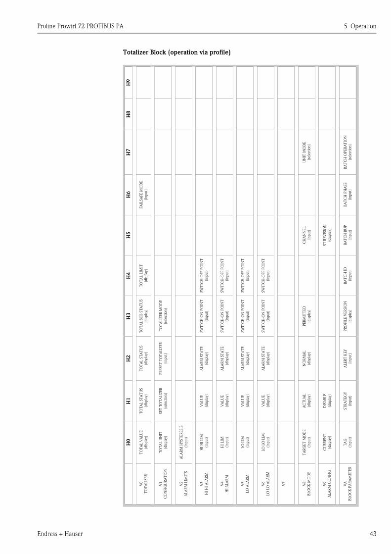
Proline Prowirl 72 PROFIBUS PA 5 Operation
Endress + Hauser 43
Totalizer Block (operation via profile)
H9
H8
H7
UN
IT M
OD
E
(sel
ecti
on)
BA
TC
H O
PE
RA
TIO
N
(sel
ecti
on)
H6
FA
ILSA
FE
MO
DE
(in
pu
t)
BA
TC
H P
HA
SE
(in
pu
t)
H5
CH
AN
NE
L
(in
pu
t)
ST
RE
VIS
ION
(dis
pla
y)
BA
TC
H R
UP
(in
pu
t)
H4
TO
TA
L L
IMIT
(dis
pla
y)
SW
ITC
H-O
FF P
OIN
T
(in
pu
t)
SW
ITC
H-O
FF P
OIN
T
(in
pu
t)
SW
ITC
H-O
FF P
OIN
T
(in
pu
t)
SW
ITC
H-O
FF P
OIN
T
(in
pu
t)
BA
TC
H I
D
(in
pu
t)
H3
TO
TA
L S
UB
ST
AT
US
(dis
pla
y)
TO
TA
LIZ
ER
MO
DE
(sel
ecti
on)
SW
ITC
H-O
N P
OIN
T
(in
pu
t)
SW
ITC
H-O
N P
OIN
T
(in
pu
t)
SW
ITC
H-O
N P
OIN
T
(in
pu
t)
SW
ITC
H-O
N P
OIN
T
(in
pu
t)
PE
RM
ITT
ED
(dis
pla
y)
PR
OFIL
E V
ER
SIO
N
(dis
pla
y)
H2
TO
TA
L S
TA
TU
S
(dis
pla
y)
PR
ESE
T T
OT
ALIZ
ER
(in
pu
t)
ALA
RM
ST
AT
E
(dis
pla
y)
ALA
RM
ST
AT
E
(dis
pla
y)
ALA
RM
ST
AT
E
(dis
pla
y)
ALA
RM
ST
AT
E
(dis
pla
y)
NO
RM
AL
(dis
pla
y)
ALE
RT
KE
Y
(in
pu
t)
H1
TO
TA
L S
TA
TU
S
(dis
pla
y)
SE
T T
OT
ALIZ
ER
(sel
ecti
on)
VA
LU
E
(dis
pla
y)
VA
LU
E
(dis
pla
y)
VA
LU
E
(dis
pla
y)
VA
LU
E
(dis
pla
y)
AC
TU
AL
(dis
pla
y)
DIS
AB
LE
(dis
pla
y)
ST
RA
TE
GY
(in
pu
t)
H0
TO
TA
L V
ALU
E
(dis
pla
y)
TO
TA
L U
NIT
(dis
pla
y)
ALA
RM
HY
ST
ER
ESIS
(in
pu
t)
HI
HI
LIM
(in
pu
t)
HI
LIM
(in
pu
t)
LO
LIM
(in
pu
t)
LO
LO
LIM
(in
pu
t)
TA
RG
ET
MO
DE
(in
pu
t)
CU
RR
EN
T
(dis
pla
y)
TA
G
(in
pu
t)
V0
TO
TA
LIZ
ER
V1
CO
NFIG
UR
AT
ION
V2
ALA
RM
LIM
ITS
V3
HI
HI
ALA
RM
V4
HI
ALA
RM
V5
LO
ALA
RM
V6
LO
LO
ALA
RM
V7
V8
BLO
CK
MO
DE
V9
ALA
RM
CO
NFIG
VA
BLO
CK
PA
RA
ME
TE
R
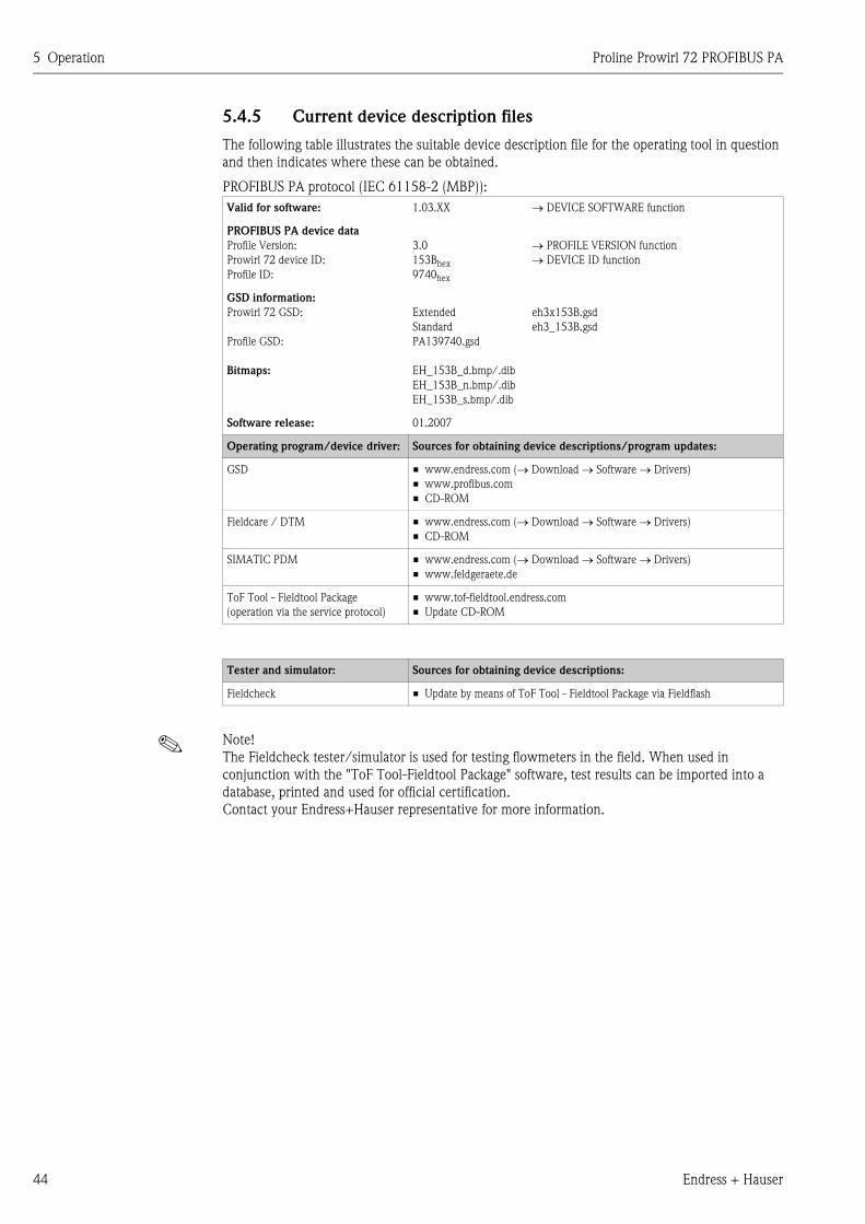
5 Operation Proline Prowirl 72 PROFIBUS PA
44 Endress + Hauser
5.4.5 Current device description files
The following table illustrates the suitable device description file for the operating tool in question
and then indicates where these can be obtained.
PROFIBUS PA protocol (IEC 61158-2 (MBP)):
! Note!
The Fieldcheck tester/simulator is used for testing flowmeters in the field. When used in
conjunction with the "ToF Tool-Fieldtool Package" software, test results can be imported into a
database, printed and used for official certification.
Contact your Endress+Hauser representative for more information.
Valid for software: 1.03.XX → DEVICE SOFTWARE function
PROFIBUS PA device data
Profile Version:
Prowirl 72 device ID:
Profile ID:
3.0
153Bhex
9740hex
→ PROFILE VERSION function
→ DEVICE ID function
GSD information:
Prowirl 72 GSD:
Profile GSD:
Bitmaps:
Extended
Standard
PA139740.gsd
EH_153B_d.bmp/.dib
EH_153B_n.bmp/.dib
EH_153B_s.bmp/.dib
eh3x153B.gsd
eh3_153B.gsd
Software release: 01.2007
Operating program/device driver: Sources for obtaining device descriptions/program updates:
GSD • www.endress.com (→ Download → Software → Drivers)
• www.profibus.com
• CD-ROM
Fieldcare / DTM • www.endress.com (→ Download → Software → Drivers)
• CD-ROM
SIMATIC PDM • www.endress.com (→ Download → Software → Drivers)
• www.feldgeraete.de
ToF Tool - Fieldtool Package
(operation via the service protocol)
• www.tof-fieldtool.endress.com
• Update CD-ROM
Tester and simulator: Sources for obtaining device descriptions:
Fieldcheck • Update by means of ToF Tool - Fieldtool Package via Fieldflash
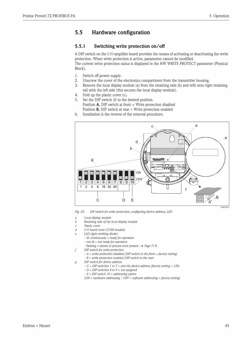
Proline Prowirl 72 PROFIBUS PA 5 Operation
Endress + Hauser 45
5.5 Hardware configuration
5.5.1 Switching write protection on/off
A DIP switch on the I/O amplifier board provides the means of activating or deactivating the write
protection. When write protection is active, parameters cannot be modified.
The current write protection status is displayed in the HW WRITE PROTECT parameter (Physical
Block).
1. Switch off power supply.
2. Unscrew the cover of the electronics compartment from the transmitter housing.
3. Remove the local display module (a) from the retaining rails (b) and refit onto right retaining
rail with the left side (this secures the local display module).
4. Fold up the plastic cover (c).
5. Set the DIP switch (f) to the desired position.
Position A, DIP switch at front = Write protection disabled
Position B, DIP switch at rear = Write protection enabled
6. Installation is the reverse of the removal procedure.
A0003876
Fig. 25: DIP switch for write protection, configuring device address, LED
a Local display module
b Retaining rails of the local display module
c Plastic cover
d I/O board cover (COM module)
e LED (light emitting diode):
– lit continuously = ready for operation
– not lit = not ready for operation
– flashing = system or process error present → Page 71 ff.
f DIP switch for write protection
– A = write protection disabled (DIP switch to the front = factory setting)
– B = write protection enabled (DIP switch to the rear)
g DIP switch for device address
– C = DIP switches 1 to 7 = sets the device address (factory setting = 126)
– D = DIP switches 8 to 9 = not assigned
– E = DIP switch 10 = addressing option
(ON = hardware addressing / OFF = software addressing = factory setting)
a
f
g
b
d
ec
DC
ON
OFF
E AB
21 5 6 7 8 9 103 4
21 16 32 644 8
5 Operation Proline Prowirl 72 PROFIBUS PA
46 Endress + Hauser
5.5.2 Configuring the device address
Note the following points:
• In the case of a PROFIBUS PA device, the address must always be configured.
The valid device addresses are in the range from 1 to 126. In a PROFIBUS PA network, each
address can only be assigned once. If an address is not configured correctly, the device is not
recognized by the master.
The address 126 can be used for initial commissioning and for service purposes.
• All devices have the address 126 and software addressing on leaving the factory.
Procedure for configuring the device address ( → Fig. 25 on Page 45):
1. Switch off power supply.
2. Unscrew the cover of the electronics compartment from the transmitter housing.
3. Remove the display module (a) from the retaining rails (b) and refit onto right retaining rail with
the left side (this secures the display module).
4. Fold up the plastic cover (c).
5. Fold up the cover (d) of the I/O board (COM module).
6. Configure the device address using DIP switches 1 to 7.
7. Activate hardware addressing using DIP switch 10 (=ON).
8. Installation is the reverse of the removal procedure.
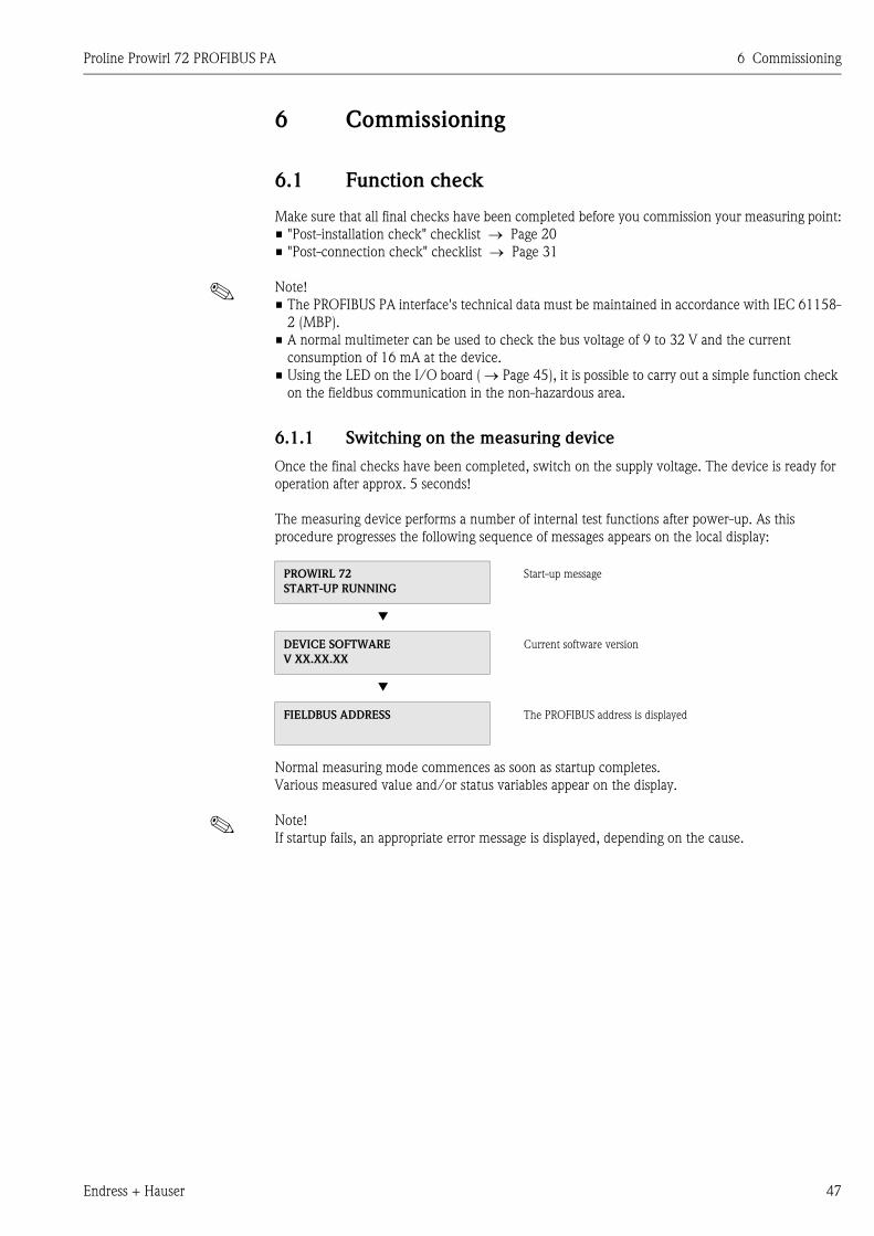
Proline Prowirl 72 PROFIBUS PA 6 Commissioning
Endress + Hauser 47
6 Commissioning
6.1 Function check
Make sure that all final checks have been completed before you commission your measuring point:
• "Post-installation check" checklist → Page 20
• "Post-connection check" checklist → Page 31
! Note!
• The PROFIBUS PA interface's technical data must be maintained in accordance with IEC 61158-
2 (MBP).
• A normal multimeter can be used to check the bus voltage of 9 to 32 V and the current
consumption of 16 mA at the device.
• Using the LED on the I/O board ( → Page 45), it is possible to carry out a simple function check
on the fieldbus communication in the non-hazardous area.
6.1.1 Switching on the measuring device
Once the final checks have been completed, switch on the supply voltage. The device is ready for
operation after approx. 5 seconds!
The measuring device performs a number of internal test functions after power-up. As this
procedure progresses the following sequence of messages appears on the local display:
Normal measuring mode commences as soon as startup completes.
Various measured value and/or status variables appear on the display.
! Note!
If startup fails, an appropriate error message is displayed, depending on the cause.
PROWIRL 72
START-UP RUNNING
Start-up message
▼
DEVICE SOFTWARE
V XX.XX.XX
Current software version
▼
FIELDBUS ADDRESS The PROFIBUS address is displayed
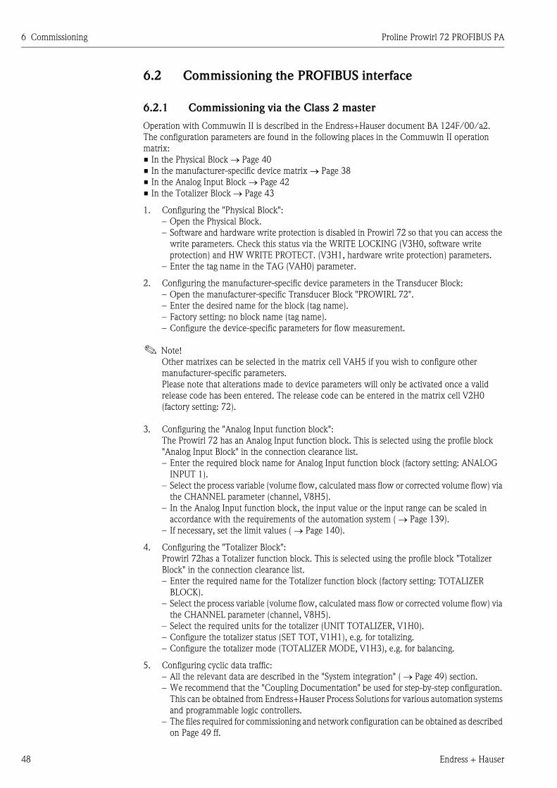
6 Commissioning Proline Prowirl 72 PROFIBUS PA
48 Endress + Hauser
6.2 Commissioning the PROFIBUS interface
6.2.1 Commissioning via the Class 2 master
Operation with Commuwin II is described in the Endress+Hauser document BA 124F/00/a2.
The configuration parameters are found in the following places in the Commuwin II operation
matrix:
• In the Physical Block → Page 40
• In the manufacturer-specific device matrix → Page 38
• In the Analog Input Block → Page 42
• In the Totalizer Block → Page 43
1. Configuring the "Physical Block":
– Open the Physical Block.
– Software and hardware write protection is disabled in Prowirl 72 so that you can access the
write parameters. Check this status via the WRITE LOCKING (V3H0, software write
protection) and HW WRITE PROTECT. (V3H1, hardware write protection) parameters.
– Enter the tag name in the TAG (VAH0) parameter.
2. Configuring the manufacturer-specific device parameters in the Transducer Block:
– Open the manufacturer-specific Transducer Block "PROWIRL 72".
– Enter the desired name for the block (tag name).
– Factory setting: no block name (tag name).
– Configure the device-specific parameters for flow measurement.
! Note!
Other matrixes can be selected in the matrix cell VAH5 if you wish to configure other
manufacturer-specific parameters.
Please note that alterations made to device parameters will only be activated once a valid
release code has been entered. The release code can be entered in the matrix cell V2H0
(factory setting: 72).
3. Configuring the "Analog Input function block":
The Prowirl 72 has an Analog Input function block. This is selected using the profile block
"Analog Input Block" in the connection clearance list.
– Enter the required block name for Analog Input function block (factory setting: ANALOG
INPUT 1).
– Select the process variable (volume flow, calculated mass flow or corrected volume flow) via
the CHANNEL parameter (channel, V8H5).
– In the Analog Input function block, the input value or the input range can be scaled in
accordance with the requirements of the automation system ( → Page 139).
– If necessary, set the limit values ( → Page 140).
4. Configuring the "Totalizer Block":
Prowirl 72has a Totalizer function block. This is selected using the profile block "Totalizer
Block" in the connection clearance list.
– Enter the required name for the Totalizer function block (factory setting: TOTALIZER
BLOCK).
– Select the process variable (volume flow, calculated mass flow or corrected volume flow) via
the CHANNEL parameter (channel, V8H5).
– Select the required units for the totalizer (UNIT TOTALIZER, V1H0).
– Configure the totalizer status (SET TOT, V1H1), e.g. for totalizing.
– Configure the totalizer mode (TOTALIZER MODE, V1H3), e.g. for balancing.
5. Configuring cyclic data traffic:
– All the relevant data are described in the "System integration" ( → Page 49) section.
– We recommend that the "Coupling Documentation" be used for step-by-step configuration.
This can be obtained from Endress+Hauser Process Solutions for various automation systems
and programmable logic controllers.
– The files required for commissioning and network configuration can be obtained as described
on Page 49 ff.
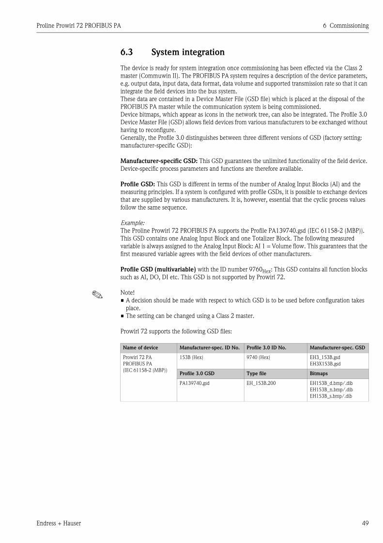
Proline Prowirl 72 PROFIBUS PA 6 Commissioning
Endress + Hauser 49
6.3 System integration
The device is ready for system integration once commissioning has been effected via the Class 2
master (Commuwin II). The PROFIBUS PA system requires a description of the device parameters,
e.g. output data, input data, data format, data volume and supported transmission rate so that it can
integrate the field devices into the bus system.
These data are contained in a Device Master File (GSD file) which is placed at the disposal of the
PROFIBUS PA master while the communication system is being commissioned.
Device bitmaps, which appear as icons in the network tree, can also be integrated. The Profile 3.0
Device Master File (GSD) allows field devices from various manufacturers to be exchanged without
having to reconfigure.
Generally, the Profile 3.0 distinguishes between three different versions of GSD (factory setting:
manufacturer-specific GSD):
Manufacturer-specific GSD: This GSD guarantees the unlimited functionality of the field device.
Device-specific process parameters and functions are therefore available.
Profile GSD: This GSD is different in terms of the number of Analog Input Blocks (AI) and the
measuring principles. If a system is configured with profile GSDs, it is possible to exchange devices
that are supplied by various manufacturers. It is, however, essential that the cyclic process values
follow the same sequence.
Example:
The Proline Prowirl 72 PROFIBUS PA supports the Profile PA139740.gsd (IEC 61158-2 (MBP)).
This GSD contains one Analog Input Block and one Totalizer Block. The following measured
variable is always assigned to the Analog Input Block: AI 1 = Volume flow. This guarantees that the
first measured variable agrees with the field devices of other manufacturers.
Profile GSD (multivariable) with the ID number 9760Hex: This GSD contains all function blocks
such as AI, DO, DI etc. This GSD is not supported by Prowirl 72.
! Note!
• A decision should be made with respect to which GSD is to be used before configuration takes
place.
• The setting can be changed using a Class 2 master.
Prowirl 72 supports the following GSD files:
Name of device Manufacturer-spec. ID No. Profile 3.0 ID No. Manufacturer-spec. GSD
Prowirl 72 PA
PROFIBUS PA
(IEC 61158-2 (MBP))
153B (Hex) 9740 (Hex) EH3_153B.gsd
EH3X153B.gsd
Profile 3.0 GSD Type file Bitmaps
PA139740.gsd EH_153B.200 EH153B_d.bmp/.dib
EH153B_n.bmp/.dib
EH153B_s.bmp/.dib
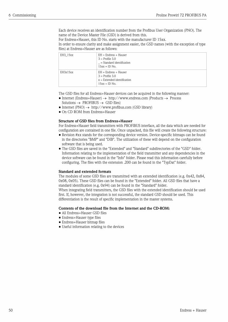
6 Commissioning Proline Prowirl 72 PROFIBUS PA
50 Endress + Hauser
Each device receives an identification number from the Profibus User Organization (PNO). The
name of the Device Master File (GSD) is derived from this.
For Endress+Hauser, this ID No. starts with the manufacturer ID 15xx.
In order to ensure clarity and make assignment easier, the GSD names (with the exception of type
files) at Endress+Hauser are as follows:
The GSD files for all Endress+Hauser devices can be acquired in the following manner:
• Internet (Endress+Hauser) → http://www.endress.com (Products → Process
Solutions → PROFIBUS → GSD files)
• Internet (PNO) → http://www.profibus.com (GSD library)
• On CD ROM from Endress+Hauser
Structure of GSD files from Endress+Hauser
For Endress+Hauser field transmitters with PROFIBUS interface, all the data which are needed for
configuration are contained in one file. Once unpacked, this file will create the following structure:
• Revision #xx stands for the corresponding device version. Device-specific bitmaps can be found
in the directories "BMP" and "DIB". The utilization of these will depend on the configuration
software that is being used.
• The GSD files are saved in the "Extended" and "Standard" subdirectories of the "GSD" folder.
Information relating to the implementation of the field transmitter and any dependencies in the
device software can be found in the "Info" folder. Please read this information carefully before
configuring. The files with the extension .200 can be found in the "TypDat" folder.
Standard and extended formats
The modules of some GSD files are transmitted with an extended identification (e.g. 0x42, 0x84,
0x08, 0x05). These GSD files can be found in the "Extended" folder. All GSD files that have a
standard identification (e.g. 0x94) can be found in the "Standard" folder.
When integrating field transmitters, the GSD files with the extended identification should be used
first. If, however, the integration is not successful, the standard GSD should be used. This
differentiation is the result of specific implementation in the master systems.
Contents of the download file from the Internet and the CD-ROM:
• All Endress+Hauser GSD files
• Endress+Hauser type files
• Endress+Hauser bitmap files
• Useful information relating to the devices
EH3_15xx EH = Endress + Hauser
3 = Profile 3.0
_ = Standard identification
15xx = ID No.
EH3x15xx EH = Endress + Hauser
3 = Profile 3.0
x = Extended identification
15xx = ID No.

Proline Prowirl 72 PROFIBUS PA 6 Commissioning
Endress + Hauser 51
Working with GSD / type files
The GSD files must be integrated into the automation system.
Depending on the software that is being used, the GSD files can be copied to the program-specific
directory or can be read into the database using the import function within the configuration
software.
Example 1:
In the case of the configuration software Siemens STEP 7 (Siemens PLC S7-300 / 400) the files are
copied to the subdirectory ...\ siemens \ step7 \ s7data \ gsd.
The GSD files also have bitmap files. These bitmap files are used to display the measuring points in
image form. The bitmap files must be saved to the directory ...\ siemens \ step7 \ s7data \ nsbmp.
Example 2:
If you have a PLC Siemens S5 where the PROFIBUS DP network is configured with the
configuration software COM ET 200, you will have to use the type files (x.200 files).
If you are using configuration software other than that referred to above, ask your PLC manufacturer
which directory you should use.
Compatibility of Profile 2.0 and 3.0 devices
It is possible to operate Profile 2.0 and 3.0 devices with different GSD files in one system using one
DP master as the cyclic data for the automation system in both profile versions are compatible.
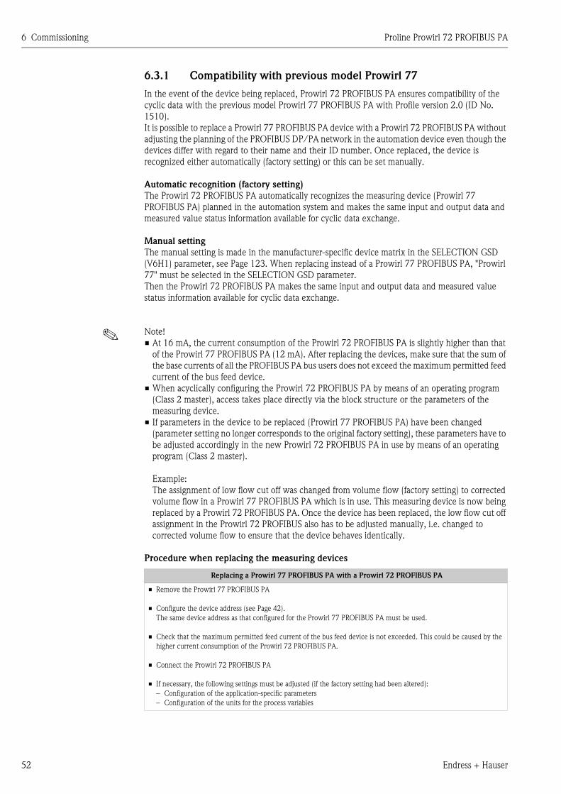
6 Commissioning Proline Prowirl 72 PROFIBUS PA
52 Endress + Hauser
6.3.1 Compatibility with previous model Prowirl 77
In the event of the device being replaced, Prowirl 72 PROFIBUS PA ensures compatibility of the
cyclic data with the previous model Prowirl 77 PROFIBUS PA with Profile version 2.0 (ID No.
1510).
It is possible to replace a Prowirl 77 PROFIBUS PA device with a Prowirl 72 PROFIBUS PA without
adjusting the planning of the PROFIBUS DP/PA network in the automation device even though the
devices differ with regard to their name and their ID number. Once replaced, the device is
recognized either automatically (factory setting) or this can be set manually.
Automatic recognition (factory setting)
The Prowirl 72 PROFIBUS PA automatically recognizes the measuring device (Prowirl 77
PROFIBUS PA) planned in the automation system and makes the same input and output data and
measured value status information available for cyclic data exchange.
Manual setting
The manual setting is made in the manufacturer-specific device matrix in the SELECTION GSD
(V6H1) parameter, see Page 123. When replacing instead of a Prowirl 77 PROFIBUS PA, "Prowirl
77" must be selected in the SELECTION GSD parameter.
Then the Prowirl 72 PROFIBUS PA makes the same input and output data and measured value
status information available for cyclic data exchange.
! Note!
• At 16 mA, the current consumption of the Prowirl 72 PROFIBUS PA is slightly higher than that
of the Prowirl 77 PROFIBUS PA (12 mA). After replacing the devices, make sure that the sum of
the base currents of all the PROFIBUS PA bus users does not exceed the maximum permitted feed
current of the bus feed device.
• When acyclically configuring the Prowirl 72 PROFIBUS PA by means of an operating program
(Class 2 master), access takes place directly via the block structure or the parameters of the
measuring device.
• If parameters in the device to be replaced (Prowirl 77 PROFIBUS PA) have been changed
(parameter setting no longer corresponds to the original factory setting), these parameters have to
be adjusted accordingly in the new Prowirl 72 PROFIBUS PA in use by means of an operating
program (Class 2 master).
Example:
The assignment of low flow cut off was changed from volume flow (factory setting) to corrected
volume flow in a Prowirl 77 PROFIBUS PA which is in use. This measuring device is now being
replaced by a Prowirl 72 PROFIBUS PA. Once the device has been replaced, the low flow cut off
assignment in the Prowirl 72 PROFIBUS also has to be adjusted manually, i.e. changed to
corrected volume flow to ensure that the device behaves identically.
Procedure when replacing the measuring devices
Replacing a Prowirl 77 PROFIBUS PA with a Prowirl 72 PROFIBUS PA
• Remove the Prowirl 77 PROFIBUS PA
• Configure the device address (see Page 42).
The same device address as that configured for the Prowirl 77 PROFIBUS PA must be used.
• Check that the maximum permitted feed current of the bus feed device is not exceeded. This could be caused by the
higher current consumption of the Prowirl 72 PROFIBUS PA.
• Connect the Prowirl 72 PROFIBUS PA
• If necessary, the following settings must be adjusted (if the factory setting had been altered):
– Configuration of the application-specific parameters
– Configuration of the units for the process variables
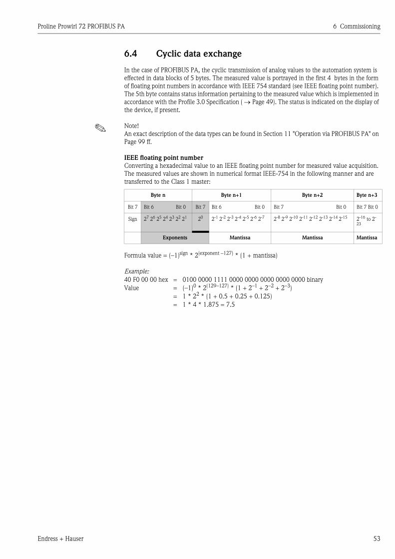
Proline Prowirl 72 PROFIBUS PA 6 Commissioning
Endress + Hauser 53
6.4 Cyclic data exchange
In the case of PROFIBUS PA, the cyclic transmission of analog values to the automation system is
effected in data blocks of 5 bytes. The measured value is portrayed in the first 4 bytes in the form
of floating point numbers in accordance with IEEE 754 standard (see IEEE floating point number).
The 5th byte contains status information pertaining to the measured value which is implemented in
accordance with the Profile 3.0 Specification ( → Page 49). The status is indicated on the display of
the device, if present.
! Note!
An exact description of the data types can be found in Section 11 "Operation via PROFIBUS PA" on
Page 99 ff.
IEEE floating point number
Converting a hexadecimal value to an IEEE floating point number for measured value acquisition.
The measured values are shown in numerical format IEEE-754 in the following manner and are
transferred to the Class 1 master:
Formula value = (–1)sign * 2(exponent –127) * (1 + mantissa)
Example:
Byte n Byte n+1 Byte n+2 Byte n+3
Bit 7 Bit 6 Bit 0 Bit 7 Bit 6 Bit 0 Bit 7 Bit 0 Bit 7 Bit 0
Sign 27 26 25 24 23 22 21 20 2-1 2-2 2-3 2-4 2-5 2-6 2-7 2-8 2-9 2-10 2-11 2-12 2-13 2-14 2-15 2-16 to 2-
23
Exponents Mantissa Mantissa Mantissa
40 F0 00 00 hex = 0100 0000 1111 0000 0000 0000 0000 0000 binary
Value = (–1)0 * 2(129–127) * (1 + 2–1 + 2–2 + 2–3)
= 1 * 22 * (1 + 0.5 + 0.25 + 0.125)
= 1 * 4 * 1.875 = 7.5
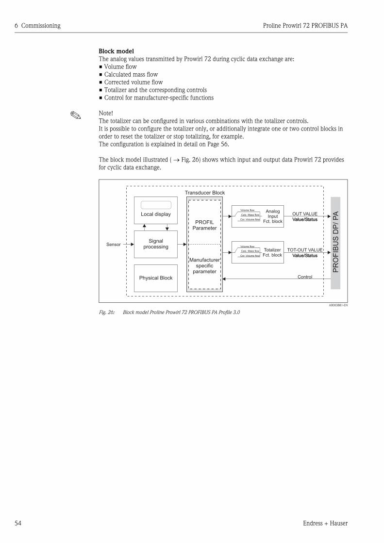
6 Commissioning Proline Prowirl 72 PROFIBUS PA
54 Endress + Hauser
Block model
The analog values transmitted by Prowirl 72 during cyclic data exchange are:
• Volume flow
• Calculated mass flow
• Corrected volume flow
• Totalizer and the corresponding controls
• Control for manufacturer-specific functions
! Note!
The totalizer can be configured in various combinations with the totalizer controls.
It is possible to configure the totalizer only, or additionally integrate one or two control blocks in
order to reset the totalizer or stop totalizing, for example.
The configuration is explained in detail on Page 56.
The block model illustrated ( → Fig. 26) shows which input and output data Prowirl 72 provides
for cyclic data exchange.
A0003881-EN
Fig. 26: Block model Proline Prowirl 72 PROFIBUS PA Profile 3.0
SensorSignal
processing
Physical Block
PROFILParameter
Manufacturerspecific
parameter
OUT VALUE
Value/Status
PR
OF
IBU
SD
P/
PA
TotalizerFct. block
TOT-OUT VALUE
Value/Status
Transducer Block
Value/Status
Value/StatusCor. Volume flow
Cor. Volume flow
Volume flow
Volume flow
Calc. Mass flow
Calc. Mass flow
Control
AnalogInput
Fct. block
Local display
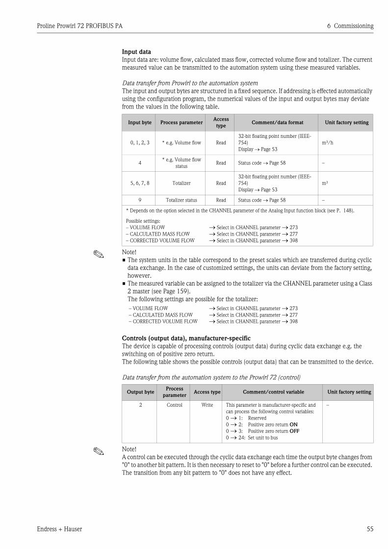
Proline Prowirl 72 PROFIBUS PA 6 Commissioning
Endress + Hauser 55
Input data
Input data are: volume flow, calculated mass flow, corrected volume flow and totalizer. The current
measured value can be transmitted to the automation system using these measured variables.
Data transfer from Prowirl to the automation system
The input and output bytes are structured in a fixed sequence. If addressing is effected automatically
using the configuration program, the numerical values of the input and output bytes may deviate
from the values in the following table.
! Note!
• The system units in the table correspond to the preset scales which are transferred during cyclic
data exchange. In the case of customized settings, the units can deviate from the factory setting,
however.
• The measured variable can be assigned to the totalizer via the CHANNEL parameter using a Class
2 master (see Page 159).
The following settings are possible for the totalizer:
Controls (output data), manufacturer-specific
The device is capable of processing controls (output data) during cyclic data exchange e.g. the
switching on of positive zero return.
The following table shows the possible controls (output data) that can be transmitted to the device.
Data transfer from the automation system to the Prowirl 72 (control)
! Note!
A control can be executed through the cyclic data exchange each time the output byte changes from
"0" to another bit pattern. It is then necessary to reset to "0" before a further control can be executed.
The transition from any bit pattern to "0" does not have any effect.
Input byte Process parameterAccess
typeComment/data format Unit factory setting
0, 1, 2, 3 * e.g. Volume flow Read
32-bit floating point number (IEEE-
754)
Display → Page 53
m³/h
4* e.g. Volume flow
statusRead Status code → Page 58 –
5, 6, 7, 8 Totalizer Read
32-bit floating point number (IEEE-
754)
Display → Page 53
m³
9 Totalizer status Read Status code → Page 58 –
* Depends on the option selected in the CHANNEL parameter of the Analog Input function block (see P. 148).
Possible settings:
– VOLUME FLOW
– CALCULATED MASS FLOW
– CORRECTED VOLUME FLOW
→ Select in CHANNEL parameter → 273
→ Select in CHANNEL parameter → 277
→ Select in CHANNEL parameter → 398
– VOLUME FLOW
– CALCULATED MASS FLOW
– CORRECTED VOLUME FLOW
→ Select in CHANNEL parameter → 273
→ Select in CHANNEL parameter → 277
→ Select in CHANNEL parameter → 398
Output byteProcess
parameterAccess type Comment/control variable Unit factory setting
2 Control Write This parameter is manufacturer-specific and
can process the following control variables:
0 → 1: Reserved
0 → 2: Positive zero return ON
0 → 3: Positive zero return OFF
0 → 24: Set unit to bus
–
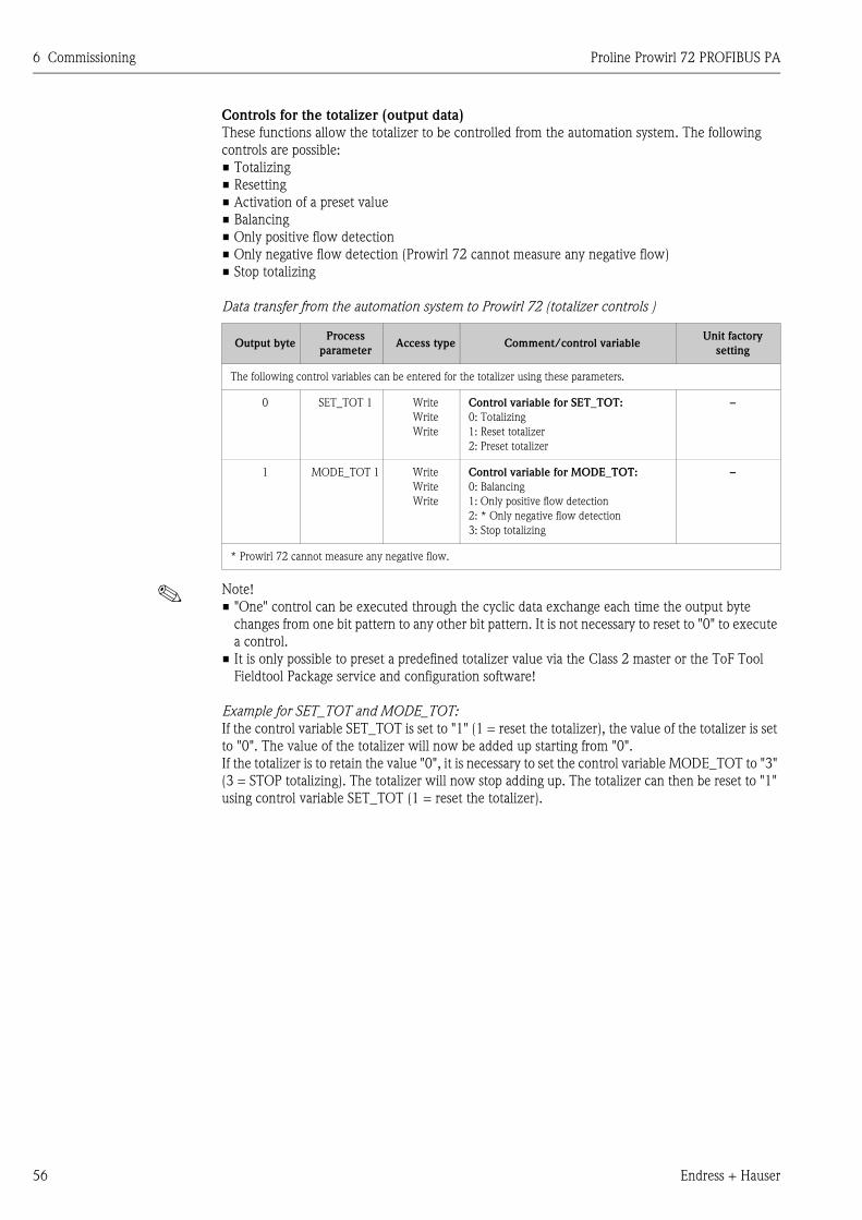
6 Commissioning Proline Prowirl 72 PROFIBUS PA
56 Endress + Hauser
Controls for the totalizer (output data)
These functions allow the totalizer to be controlled from the automation system. The following
controls are possible:
• Totalizing
• Resetting
• Activation of a preset value
• Balancing
• Only positive flow detection
• Only negative flow detection (Prowirl 72 cannot measure any negative flow)
• Stop totalizing
Data transfer from the automation system to Prowirl 72 (totalizer controls )
! Note!
• "One" control can be executed through the cyclic data exchange each time the output byte
changes from one bit pattern to any other bit pattern. It is not necessary to reset to "0" to execute
a control.
• It is only possible to preset a predefined totalizer value via the Class 2 master or the ToF Tool
Fieldtool Package service and configuration software!
Example for SET_TOT and MODE_TOT:
If the control variable SET_TOT is set to "1" (1 = reset the totalizer), the value of the totalizer is set
to "0". The value of the totalizer will now be added up starting from "0".
If the totalizer is to retain the value "0", it is necessary to set the control variable MODE_TOT to "3"
(3 = STOP totalizing). The totalizer will now stop adding up. The totalizer can then be reset to "1"
using control variable SET_TOT (1 = reset the totalizer).
Output byteProcess
parameterAccess type Comment/control variable
Unit factory
setting
The following control variables can be entered for the totalizer using these parameters.
0 SET_TOT 1 Write
Write
Write
Control variable for SET_TOT:
0: Totalizing
1: Reset totalizer
2: Preset totalizer
–
1 MODE_TOT 1 Write
Write
Write
Control variable for MODE_TOT:
0: Balancing
1: Only positive flow detection
2: * Only negative flow detection
3: Stop totalizing
–
* Prowirl 72 cannot measure any negative flow.
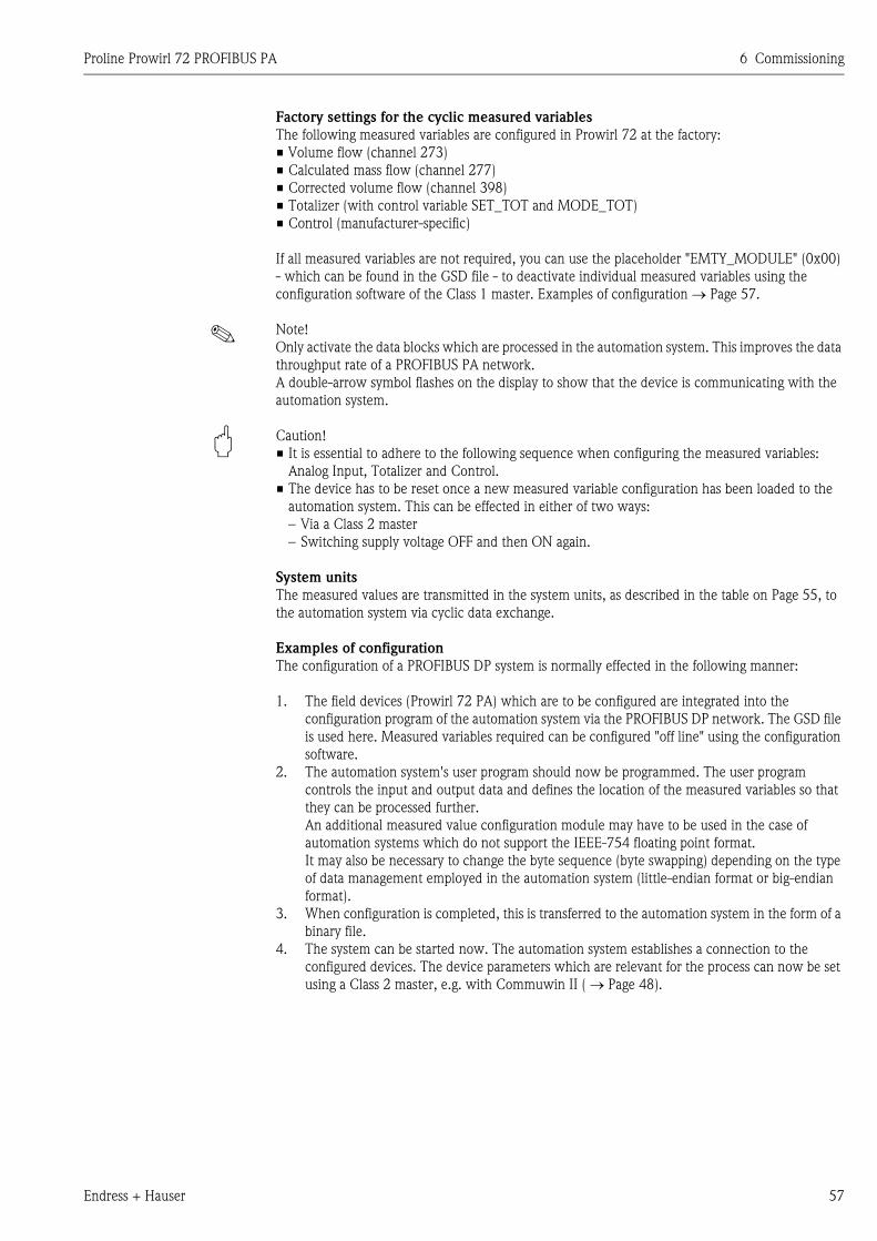
Proline Prowirl 72 PROFIBUS PA 6 Commissioning
Endress + Hauser 57
Factory settings for the cyclic measured variables
The following measured variables are configured in Prowirl 72 at the factory:
• Volume flow (channel 273)
• Calculated mass flow (channel 277)
• Corrected volume flow (channel 398)
• Totalizer (with control variable SET_TOT and MODE_TOT)
• Control (manufacturer-specific)
If all measured variables are not required, you can use the placeholder "EMTY_MODULE" (0x00)
- which can be found in the GSD file - to deactivate individual measured variables using the
configuration software of the Class 1 master. Examples of configuration → Page 57.
! Note!
Only activate the data blocks which are processed in the automation system. This improves the data
throughput rate of a PROFIBUS PA network.
A double-arrow symbol flashes on the display to show that the device is communicating with the
automation system.
" Caution!
• It is essential to adhere to the following sequence when configuring the measured variables:
Analog Input, Totalizer and Control.
• The device has to be reset once a new measured variable configuration has been loaded to the
automation system. This can be effected in either of two ways:
– Via a Class 2 master
– Switching supply voltage OFF and then ON again.
System units
The measured values are transmitted in the system units, as described in the table on Page 55, to
the automation system via cyclic data exchange.
Examples of configuration
The configuration of a PROFIBUS DP system is normally effected in the following manner:
1. The field devices (Prowirl 72 PA) which are to be configured are integrated into the
configuration program of the automation system via the PROFIBUS DP network. The GSD file
is used here. Measured variables required can be configured "off line" using the configuration
software.
2. The automation system's user program should now be programmed. The user program
controls the input and output data and defines the location of the measured variables so that
they can be processed further.
An additional measured value configuration module may have to be used in the case of
automation systems which do not support the IEEE-754 floating point format.
It may also be necessary to change the byte sequence (byte swapping) depending on the type
of data management employed in the automation system (little-endian format or big-endian
format).
3. When configuration is completed, this is transferred to the automation system in the form of a
binary file.
4. The system can be started now. The automation system establishes a connection to the
configured devices. The device parameters which are relevant for the process can now be set
using a Class 2 master, e.g. with Commuwin II ( → Page 48).
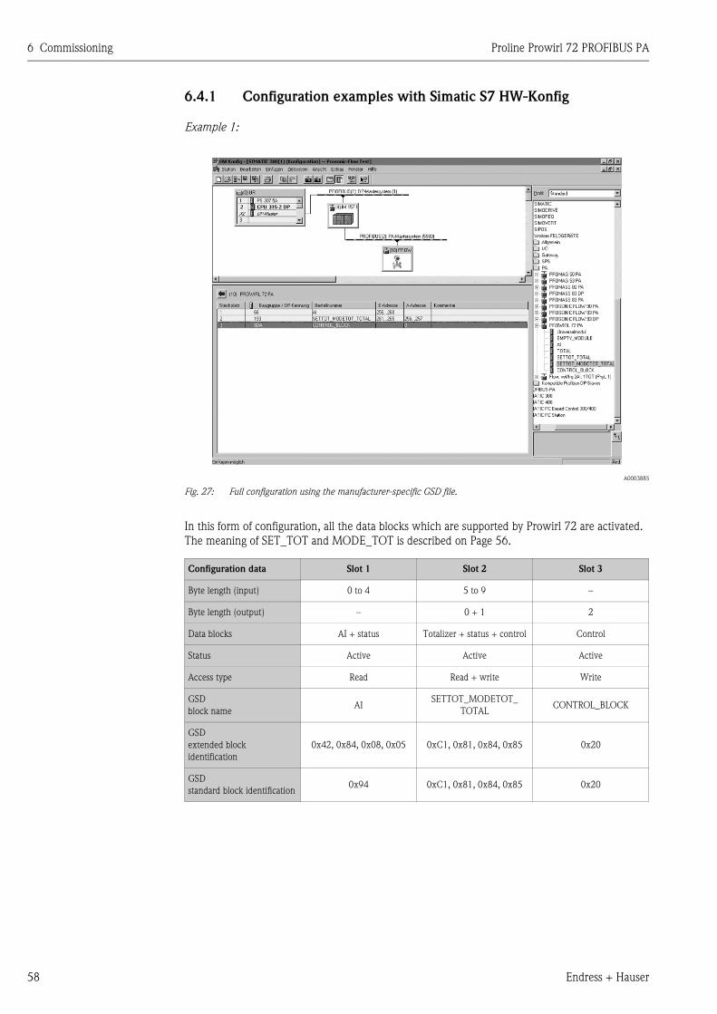
6 Commissioning Proline Prowirl 72 PROFIBUS PA
58 Endress + Hauser
6.4.1 Configuration examples with Simatic S7 HW-Konfig
Example 1:
A0003885
Fig. 27: Full configuration using the manufacturer-specific GSD file.
In this form of configuration, all the data blocks which are supported by Prowirl 72 are activated.
The meaning of SET_TOT and MODE_TOT is described on Page 56.
Configuration data Slot 1 Slot 2 Slot 3
Byte length (input) 0 to 4 5 to 9 –
Byte length (output) – 0 + 1 2
Data blocks AI + status Totalizer + status + control Control
Status Active Active Active
Access type Read Read + write Write
GSD
block nameAI
SETTOT_MODETOT_
TOTALCONTROL_BLOCK
GSD
extended block
identification
0x42, 0x84, 0x08, 0x05 0xC1, 0x81, 0x84, 0x85 0x20
GSD
standard block identification0x94 0xC1, 0x81, 0x84, 0x85 0x20
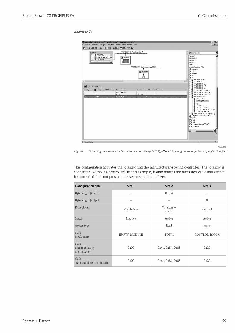
Proline Prowirl 72 PROFIBUS PA 6 Commissioning
Endress + Hauser 59
Example 2:
A0003888
Fig. 28: Replacing measured variables with placeholders (EMPTY_MODULE) using the manufacturer-specific GSD file:
This configuration activates the totalizer and the manufacturer-specific controller. The totalizer is
configured "without a controller". In this example, it only returns the measured value and cannot
be controlled. It is not possible to reset or stop the totalizer.
Configuration data Slot 1 Slot 2 Slot 3
Byte length (input) – 0 to 4 –
Byte length (output) – – 0
Data blocksPlaceholder
Totalizer +
statusControl
Status Inactive Active Active
Access type – Read Write
GSD
block nameEMPTY_MODULE TOTAL CONTROL_BLOCK
GSD
extended block
identification
0x00 0x41, 0x84, 0x85 0x20
GSD
standard block identification0x00 0x41, 0x84, 0x85 0x20
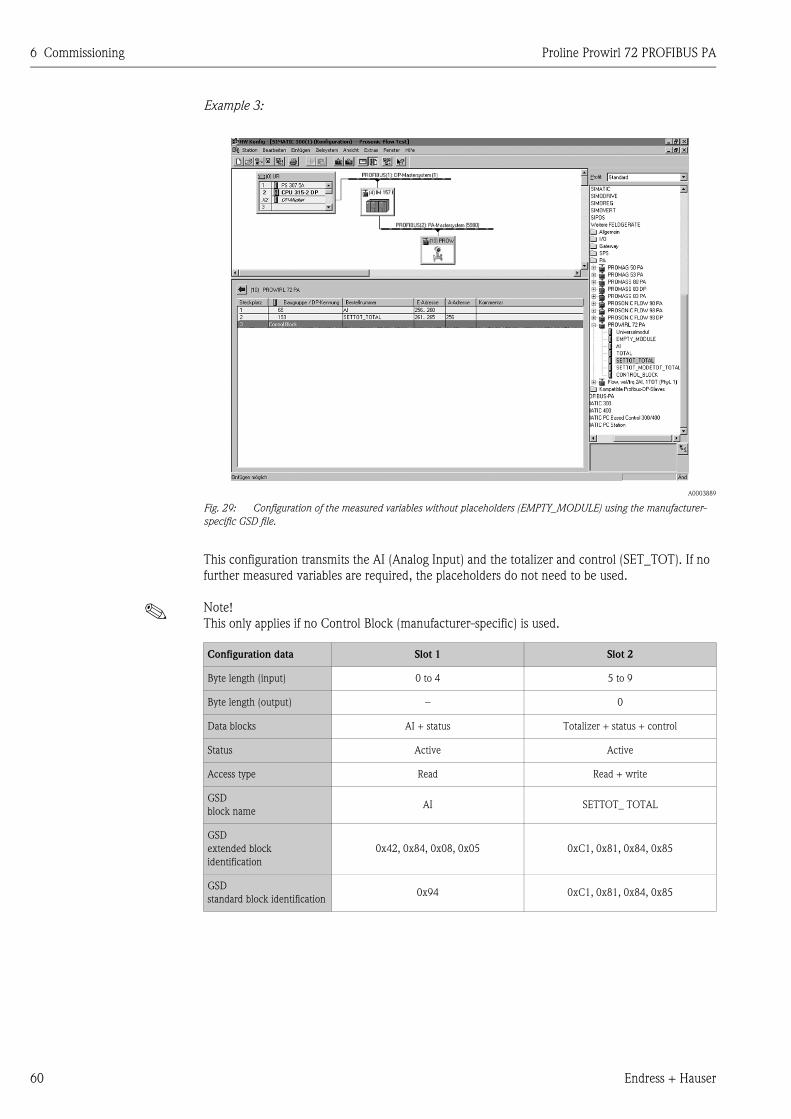
6 Commissioning Proline Prowirl 72 PROFIBUS PA
60 Endress + Hauser
Example 3:
A0003889
Fig. 29: Configuration of the measured variables without placeholders (EMPTY_MODULE) using the manufacturer-
specific GSD file.
This configuration transmits the AI (Analog Input) and the totalizer and control (SET_TOT). If no
further measured variables are required, the placeholders do not need to be used.
! Note!
This only applies if no Control Block (manufacturer-specific) is used.
Configuration data Slot 1 Slot 2
Byte length (input) 0 to 4 5 to 9
Byte length (output) – 0
Data blocks AI + status Totalizer + status + control
Status Active Active
Access type Read Read + write
GSD
block nameAI SETTOT_ TOTAL
GSD
extended block
identification
0x42, 0x84, 0x08, 0x05 0xC1, 0x81, 0x84, 0x85
GSD
standard block identification0x94 0xC1, 0x81, 0x84, 0x85
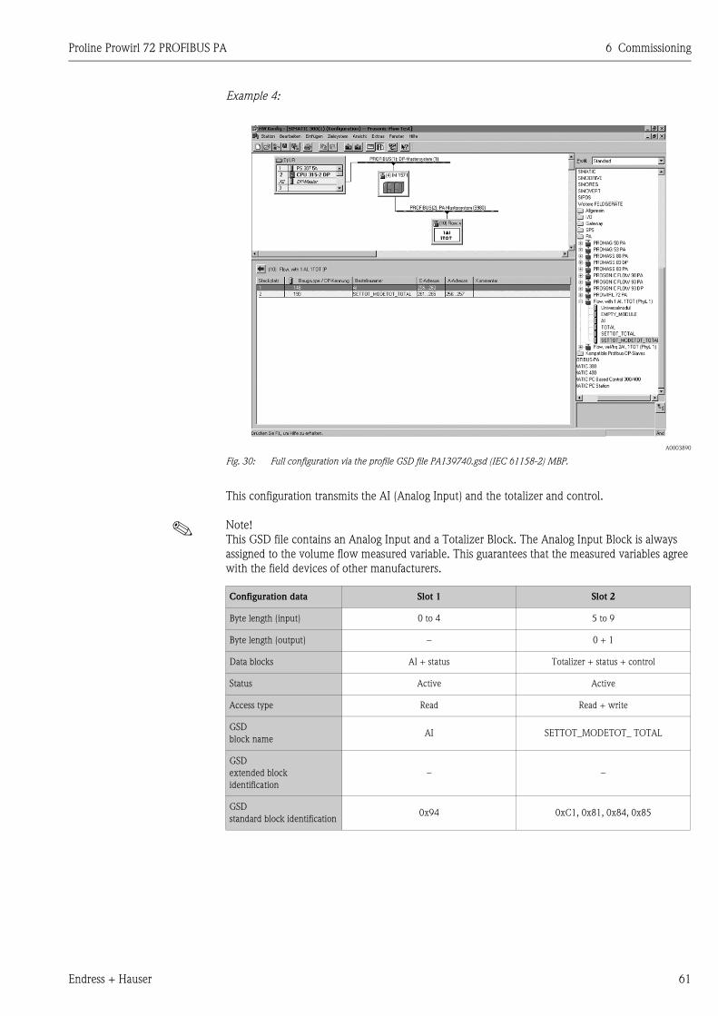
Proline Prowirl 72 PROFIBUS PA 6 Commissioning
Endress + Hauser 61
Example 4:
A0003890
Fig. 30: Full configuration via the profile GSD file PA139740.gsd (IEC 61158-2) MBP.
This configuration transmits the AI (Analog Input) and the totalizer and control.
! Note!
This GSD file contains an Analog Input and a Totalizer Block. The Analog Input Block is always
assigned to the volume flow measured variable. This guarantees that the measured variables agree
with the field devices of other manufacturers.
Configuration data Slot 1 Slot 2
Byte length (input) 0 to 4 5 to 9
Byte length (output) – 0 + 1
Data blocks AI + status Totalizer + status + control
Status Active Active
Access type Read Read + write
GSD
block nameAI SETTOT_MODETOT_ TOTAL
GSD
extended block
identification
– –
GSD
standard block identification0x94 0xC1, 0x81, 0x84, 0x85
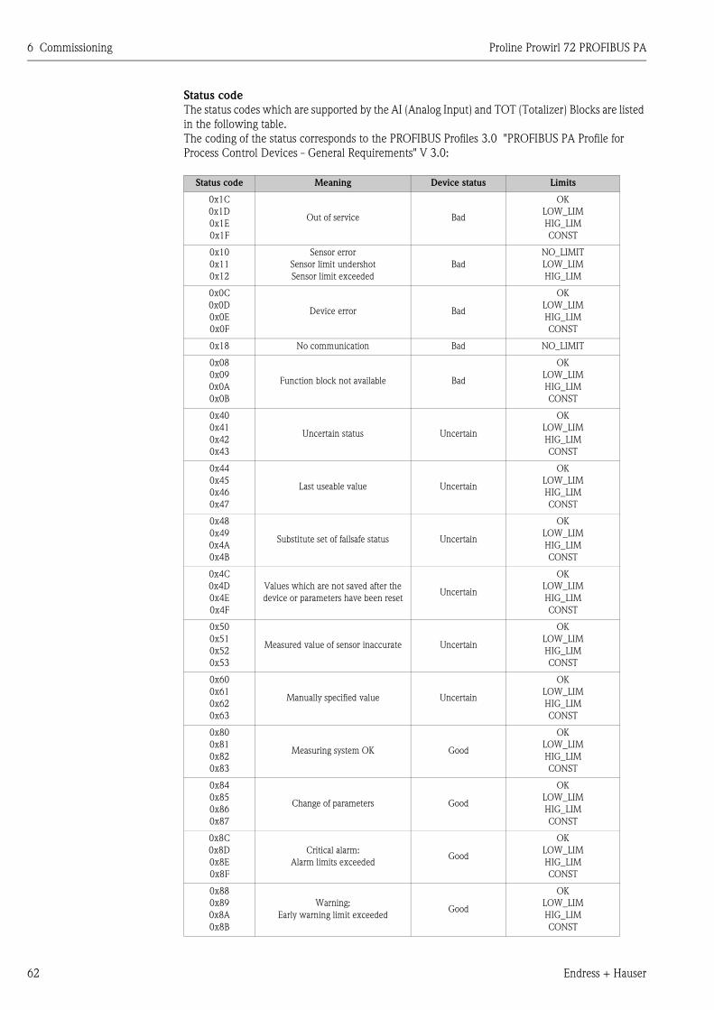
6 Commissioning Proline Prowirl 72 PROFIBUS PA
62 Endress + Hauser
Status code
The status codes which are supported by the AI (Analog Input) and TOT (Totalizer) Blocks are listed
in the following table.
The coding of the status corresponds to the PROFIBUS Profiles 3.0 "PROFIBUS PA Profile for
Process Control Devices - General Requirements" V 3.0:
Status code Meaning Device status Limits
0x1C
0x1D
0x1E
0x1F
Out of service Bad
OK
LOW_LIM
HIG_LIM
CONST
0x10
0x11
0x12
Sensor error
Sensor limit undershot
Sensor limit exceeded
Bad
NO_LIMIT
LOW_LIM
HIG_LIM
0x0C
0x0D
0x0E
0x0F
Device error Bad
OK
LOW_LIM
HIG_LIM
CONST
0x18 No communication Bad NO_LIMIT
0x08
0x09
0x0A
0x0B
Function block not available Bad
OK
LOW_LIM
HIG_LIM
CONST
0x40
0x41
0x42
0x43
Uncertain status Uncertain
OK
LOW_LIM
HIG_LIM
CONST
0x44
0x45
0x46
0x47
Last useable value Uncertain
OK
LOW_LIM
HIG_LIM
CONST
0x48
0x49
0x4A
0x4B
Substitute set of failsafe status Uncertain
OK
LOW_LIM
HIG_LIM
CONST
0x4C
0x4D
0x4E
0x4F
Values which are not saved after the
device or parameters have been resetUncertain
OK
LOW_LIM
HIG_LIM
CONST
0x50
0x51
0x52
0x53
Measured value of sensor inaccurate Uncertain
OK
LOW_LIM
HIG_LIM
CONST
0x60
0x61
0x62
0x63
Manually specified value Uncertain
OK
LOW_LIM
HIG_LIM
CONST
0x80
0x81
0x82
0x83
Measuring system OK Good
OK
LOW_LIM
HIG_LIM
CONST
0x84
0x85
0x86
0x87
Change of parameters Good
OK
LOW_LIM
HIG_LIM
CONST
0x8C
0x8D
0x8E
0x8F
Critical alarm:
Alarm limits exceededGood
OK
LOW_LIM
HIG_LIM
CONST
0x88
0x89
0x8A
0x8B
Warning:
Early warning limit exceededGood
OK
LOW_LIM
HIG_LIM
CONST
Proline Prowirl 72 PROFIBUS PA 6 Commissioning
Endress + Hauser 63
6.5 Acyclic data exchange
Acyclic data exchange is used to transfer parameters during commissioning and maintenance or to
display other measured variables that are not contained in the useful cyclic data traffic. Thus,
parameters for recognizing, for controlling or for adjusting can be changed in the various blocks
(Physical Block, Transducer Block, function block) while the device is involved in cyclic data
exchange with a PLC.
When observing acyclic communication, a distinction must be made between two types:
6.5.1 Class 2 master acyclic (MS2AC)
MS2AC deals with acyclic communication between a field device and a Class 2 master (e.g.
Fieldcare, Commuwin, PDM etc., see Page 36). Here, the master opens a communication channel
by means of an SAP (service access point) to access the device.
A Class 2 master must be made aware of all the parameters which should be exchanged with a
device by means of PROFIBUS. This assignment is made to each individual parameter either in a
device description (DD), a DTM (Device Type Manager) or within a software component in the
master via slot and index addressing.
The following should be noted with MS2AC communication:
• As already explained, a Class 2 master accesses a device by means of special SAPs. Thus, the
number of Class 2 masters that can simultaneously communicate with a device is restricted to the
number of SAPs made available for this communication.
• When a Class 2 master is used, the cycle time of the bus system increases.
This should be taken into account when programming the control system used.
6.5.2 Class 1 master acyclic (MS1AC)
In the case of MS1AC, a cyclic master, which is already reading the cyclic data from the device or
writing the data to the device, opens the communication channel via the SAP 0x33 (special service
access point for MS1AC) and can then, like a Class 2 master, acyclically read or write a parameter
by means of the slot and the index (if supported).
The following should be noted with MS1AC communication:
• At present, there are very few PROFIBUS masters on the market that support this kind of
communication.
• Not all PROFIBUS devices support MS1AC.
• In the user program, you must be aware that constant parameter writing (e.g. with every program
cycle) can drastically reduce the operating life of a device. Parameters written acyclically are
written to memory modules (EEPROM, Flash, etc.). These are resistant to voltage. These memory
modules are only designed for a limited number of writes. This number of writes is not even
nearly reached in normal operation without MS1AC (during configuration). This maximum figure
can be quickly reached as a result of incorrect programming and thus the operating time of a
device can be drastically reduced.
The measuring device supports MS2AC communication with 2 available SAPs.
MS1AC communication is supported by the device.
The memory module is designed for 106 writes.

6 Commissioning Proline Prowirl 72 PROFIBUS PA
64 Endress + Hauser
Proline Prowirl 72 PROFIBUS PA 7 Maintenance
Endress + Hauser 65
7 Maintenance
The flowmeter system requires no special maintenance.
Exterior cleaning
When cleaning the exterior of measuring devices, always use cleaning agents that do not attack the
surface of the housing and the seals.
Cleaning with pigs
Cleaning with pigs is not possible!
Replacing sensor seals
Under normal circumstances, wetted seals must not be replaced. Replacement is necessary only in
special circumstances, for example if aggressive or corrosive fluids are incompatible with the seal
material.
! Note!
• The time span between the individual replacements depends on the fluid properties.
• Replacement seals (accessory) → Page 67.
Only sensor seals from Endress+Hauser can be used.
Replacing housing seals
The housing seals must be clean and undamaged when inserted into their grooves.
The seals must be dried, cleaned or replaced if necessary.
! Note!
If the measuring device is used in a dust atmosphere, only the associated housing seals from
Endress+Hauser should be used.

7 Maintenance Proline Prowirl 72 PROFIBUS PA
66 Endress + Hauser
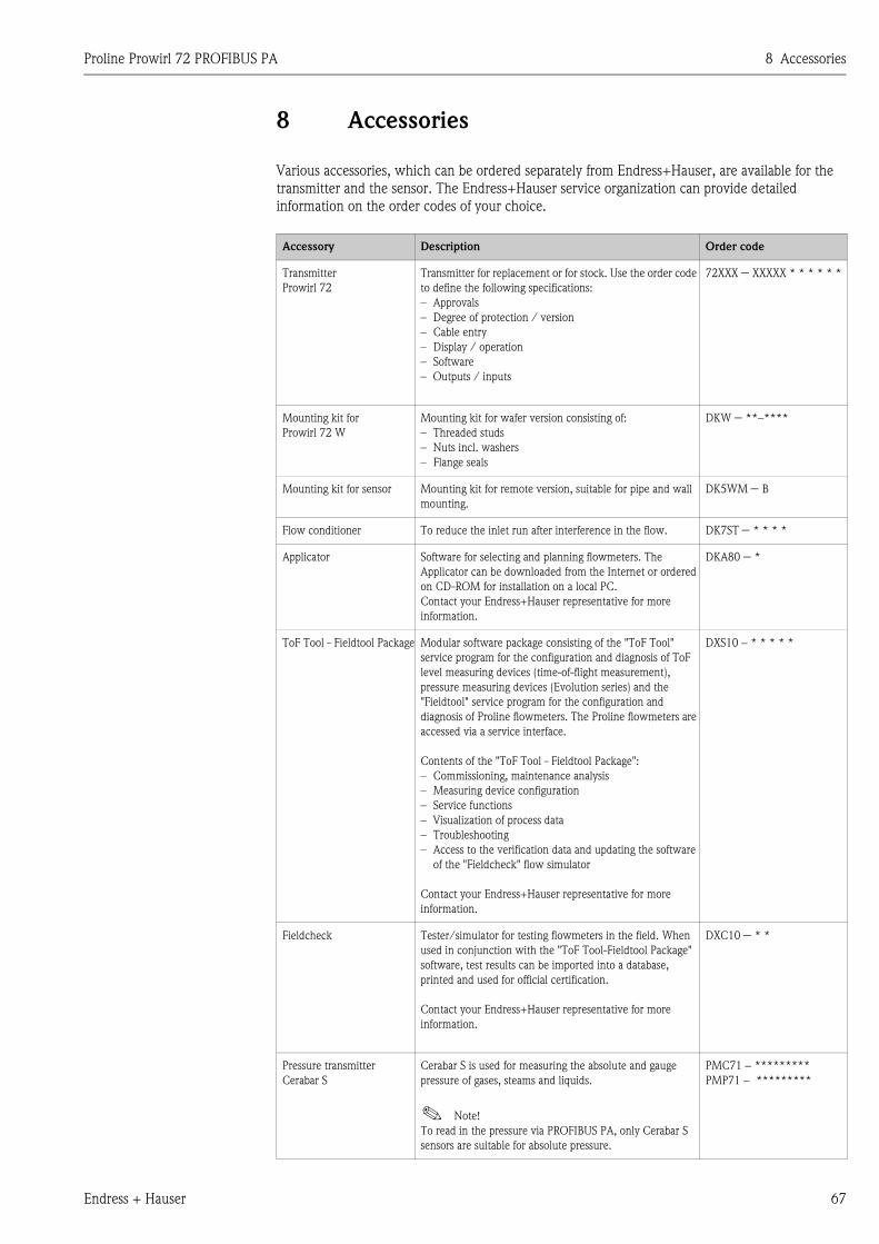
Proline Prowirl 72 PROFIBUS PA 8 Accessories
Endress + Hauser 67
8 Accessories
Various accessories, which can be ordered separately from Endress+Hauser, are available for the
transmitter and the sensor. The Endress+Hauser service organization can provide detailed
information on the order codes of your choice.
Accessory Description Order code
Transmitter
Prowirl 72
Transmitter for replacement or for stock. Use the order code
to define the following specifications:
– Approvals
– Degree of protection / version
– Cable entry
– Display / operation
– Software
– Outputs / inputs
72XXX − XXXXX * * * * * *
Mounting kit for
Prowirl 72 W
Mounting kit for wafer version consisting of:
– Threaded studs
– Nuts incl. washers
– Flange seals
DKW − **–****
Mounting kit for sensor Mounting kit for remote version, suitable for pipe and wall
mounting.
DK5WM − B
Flow conditioner To reduce the inlet run after interference in the flow. DK7ST − * * * *
Applicator Software for selecting and planning flowmeters. The
Applicator can be downloaded from the Internet or ordered
on CD-ROM for installation on a local PC.
Contact your Endress+Hauser representative for more
information.
DKA80 − *
ToF Tool - Fieldtool Package Modular software package consisting of the "ToF Tool"
service program for the configuration and diagnosis of ToF
level measuring devices (time-of-flight measurement),
pressure measuring devices (Evolution series) and the
"Fieldtool" service program for the configuration and
diagnosis of Proline flowmeters. The Proline flowmeters are
accessed via a service interface.
Contents of the "ToF Tool - Fieldtool Package":
– Commissioning, maintenance analysis
– Measuring device configuration
– Service functions
– Visualization of process data
– Troubleshooting
– Access to the verification data and updating the software
of the "Fieldcheck" flow simulator
Contact your Endress+Hauser representative for more
information.
DXS10 − * * * * *
Fieldcheck Tester/simulator for testing flowmeters in the field. When
used in conjunction with the "ToF Tool-Fieldtool Package"
software, test results can be imported into a database,
printed and used for official certification.
Contact your Endress+Hauser representative for more
information.
DXC10 − * *
Pressure transmitter
Cerabar S
Cerabar S is used for measuring the absolute and gauge
pressure of gases, steams and liquids.
! Note!
To read in the pressure via PROFIBUS PA, only Cerabar S
sensors are suitable for absolute pressure.
PMC71 − *********
PMP71 − *********
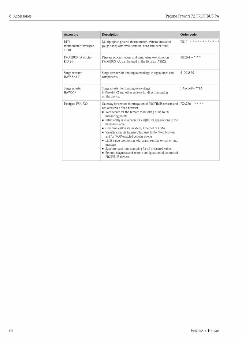
8 Accessories Proline Prowirl 72 PROFIBUS PA
68 Endress + Hauser
RTD
thermometer Omnigrad
TR10
Multipurpose process thermometer. Mineral insulated
gauge slide; with well, terminal head and neck tube.
TR10 - * * * * * * * * * * * *
PROFIBUS PA display
RID 261
Displays process values and limit value overshoot on
PROFIBUS PA, can be used in the Ex area (ATEX).
RID261 − * * *
Surge arrester
HAW 562 Z
Surge arrester for limiting overvoltage in signal lines and
components.
51003575
Surge arrester
HAW569
Surge arrester for limiting overvoltage
in Prowirl 72 and other sensors for direct mounting
on the device.
HAW569 - **1A
Fieldgate FXA 720 Gateway for remote interrogation of PROFIBUS sensors and
actuators via a Web browser
• Web server for the remote monitoring of up to 30
measuring points
• Intrinsically safe version [EEx ia]IIC for applications in the
hazardous area
• Communication via modem, Ethernet or GSM
• Visualization via Internet/Intranet in the Web browser
and/or WAP-enabled cellular phone
• Limit value monitoring with alarm sent by e-mail or text
message
• Synchronized time-stamping for all measured values
• Remote diagnosis and remote configuration of connected
PROFIBUS devices
FXA720 − * * * *
Accessory Description Order code
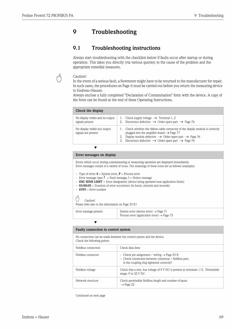
Proline Prowirl 72 PROFIBUS PA 9 Troubleshooting
Endress + Hauser 69
9 Troubleshooting
9.1 Troubleshooting instructions
Always start troubleshooting with the checklists below if faults occur after startup or during
operation. This takes you directly (via various queries) to the cause of the problem and the
appropriate remedial measures.
" Caution!
In the event of a serious fault, a flowmeter might have to be returned to the manufacturer for repair.
In such cases, the procedures on Page 6 must be carried out before you return the measuring device
to Endress+Hauser.
Always enclose a fully completed "Declaration of Contamination" form with the device. A copy of
the form can be found at the end of these Operating Instructions.
Check the display
No display visible and no output
signals present
1. Check supply voltage → Terminal 1, 2
2. Electronics defective → Order spare part → Page 76
No display visible but output
signals are present
1. Check whether the ribbon-cable connector of the display module is correctly
plugged into the amplifier board → Page 77
2. Display module defective → Order spare part → Page 76
3. Electronics defective → Order spare part → Page 76
▼
Error messages on display
Errors which occur during commissioning or measuring operation are displayed immediately.
Error messages consist of a variety of icons. The meanings of these icons are as follows (example):
– Type of error: S = System error, P = Process error
– Error message type: $ = Fault message, ! = Notice message
– DSC SENS LIMIT = Error designation (device being operated near application limits)
– 03:00:05 = Duration of error occurrence (in hours, minutes and seconds)
– #395 = Error number
" Caution!
Please refer also to the information on Page 35 ff.!
Error message present System error (device error) → Page 71
Process error (application error) → Page 73
▼
Faulty connection to control system
No connection can be made between the control system and the device.
Check the following points:
Fieldbus connection Check data lines
Fieldbus connector – Check pin assignment / wiring → Page 25 ff.
– Check connection between connector / fieldbus port.
Is the coupling ring tightened correctly?
Fieldbus voltage Check that a min. bus voltage of 9 V DC is present at terminals 1/2. Permissible
range: 9 to 32 V DC
Network structure Check permissible fieldbus length and number of spurs.
→ Page 22
Continued on next page
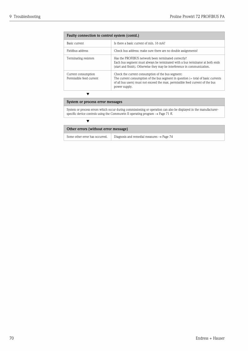
9 Troubleshooting Proline Prowirl 72 PROFIBUS PA
70 Endress + Hauser
Faulty connection to control system (contd.)
Basic current Is there a basic current of min. 16 mA?
Fieldbus address Check bus address: make sure there are no double assignments!
Terminating resistors Has the PROFIBUS network been terminated correctly?
Each bus segment must always be terminated with a bus terminator at both ends
(start and finish). Otherwise they may be interference in communication.
Current consumption
Permissible feed current
Check the current consumption of the bus segment:
The current consumption of the bus segment in question (= total of basic currents
of all bus users) must not exceed the max. permissible feed current of the bus
power supply.
▼
System or process error messages
System or process errors which occur during commissioning or operation can also be displayed in the manufacturer-
specific device controls using the Commuwin II operating program → Page 71 ff.
▼
Other errors (without error message)
Some other error has occurred. Diagnosis and remedial measures → Page 74
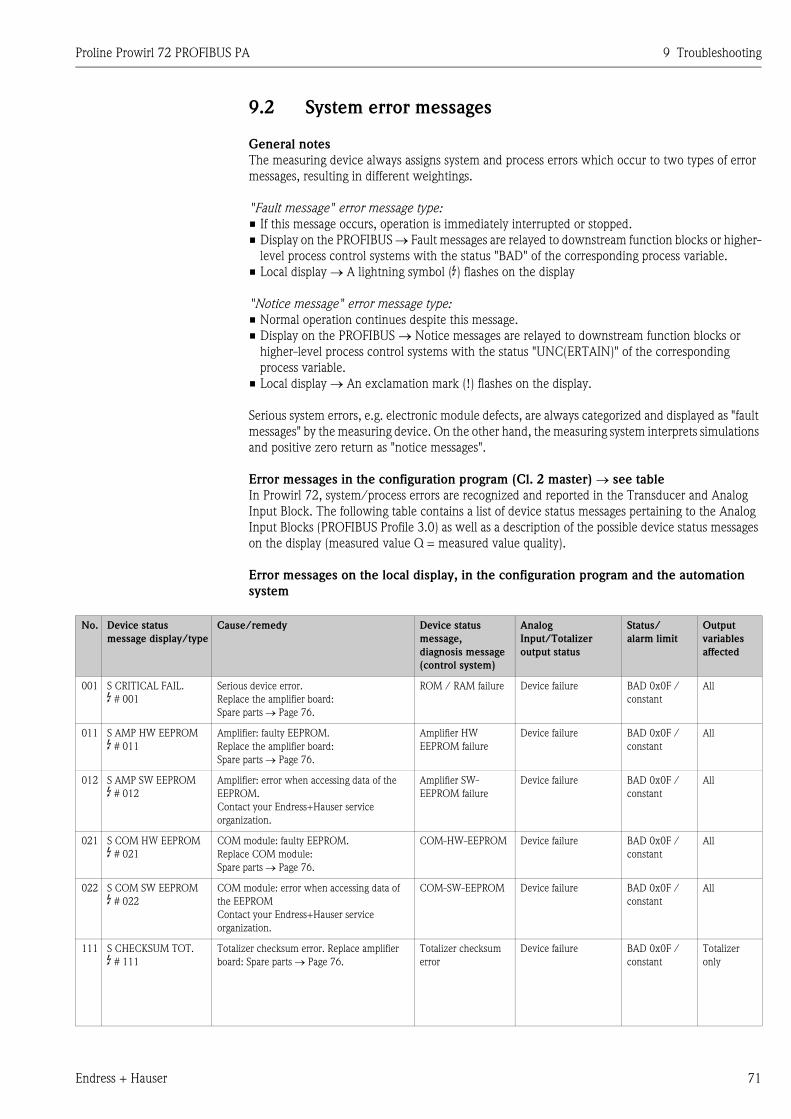
Proline Prowirl 72 PROFIBUS PA 9 Troubleshooting
Endress + Hauser 71
9.2 System error messages
General notes
The measuring device always assigns system and process errors which occur to two types of error
messages, resulting in different weightings.
"Fault message" error message type:
• If this message occurs, operation is immediately interrupted or stopped.
• Display on the PROFIBUS → Fault messages are relayed to downstream function blocks or higher-
level process control systems with the status "BAD" of the corresponding process variable.
• Local display → A lightning symbol ($) flashes on the display
"Notice message" error message type:
• Normal operation continues despite this message.
• Display on the PROFIBUS → Notice messages are relayed to downstream function blocks or
higher-level process control systems with the status "UNC(ERTAIN)" of the corresponding
process variable.
• Local display → An exclamation mark (!) flashes on the display.
Serious system errors, e.g. electronic module defects, are always categorized and displayed as "fault
messages" by the measuring device. On the other hand, the measuring system interprets simulations
and positive zero return as "notice messages".
Error messages in the configuration program (Cl. 2 master) → see table
In Prowirl 72, system/process errors are recognized and reported in the Transducer and Analog
Input Block. The following table contains a list of device status messages pertaining to the Analog
Input Blocks (PROFIBUS Profile 3.0) as well as a description of the possible device status messages
on the display (measured value Q = measured value quality).
Error messages on the local display, in the configuration program and the automation
system
No. Device status
message display/type
Cause/remedy Device status
message,
diagnosis message
(control system)
Analog
Input/Totalizer
output status
Status/
alarm limit
Output
variables
affected
001 S CRITICAL FAIL.
$ # 001
Serious device error.
Replace the amplifier board:
Spare parts → Page 76.
ROM / RAM failure Device failure BAD 0x0F /
constant
All
011 S AMP HW EEPROM
$ # 011
Amplifier: faulty EEPROM.
Replace the amplifier board:
Spare parts → Page 76.
Amplifier HW
EEPROM failure
Device failure BAD 0x0F /
constant
All
012 S AMP SW EEPROM
$ # 012
Amplifier: error when accessing data of the
EEPROM.
Contact your Endress+Hauser service
organization.
Amplifier SW-
EEPROM failure
Device failure BAD 0x0F /
constant
All
021 S COM HW EEPROM
$ # 021
COM module: faulty EEPROM.
Replace COM module:
Spare parts → Page 76.
COM-HW-EEPROM Device failure BAD 0x0F /
constant
All
022 S COM SW EEPROM
$ # 022
COM module: error when accessing data of
the EEPROM
Contact your Endress+Hauser service
organization.
COM-SW-EEPROM Device failure BAD 0x0F /
constant
All
111 S CHECKSUM TOT.
$ # 111
Totalizer checksum error. Replace amplifier
board: Spare parts → Page 76.
Totalizer checksum
error
Device failure BAD 0x0F /
constant
Totalizer
only
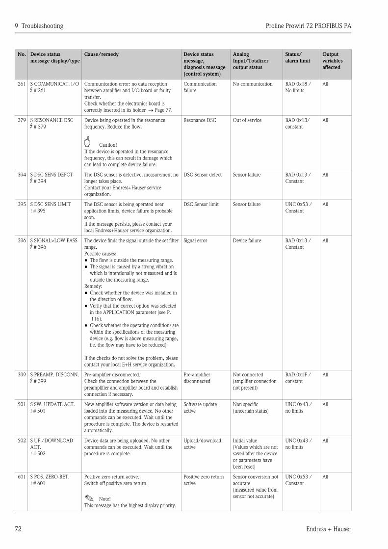
9 Troubleshooting Proline Prowirl 72 PROFIBUS PA
72 Endress + Hauser
261 S COMMUNICAT. I/O
$ # 261
Communication error: no data reception
between amplifier and I/O board or faulty
transfer.
Check whether the electronics board is
correctly inserted in its holder → Page 77.
Communication
failure
No communication BAD 0x18 /
No limits
All
379 S RESONANCE DSC
$ # 379
Device being operated in the resonance
frequency. Reduce the flow.
" Caution!
If the device is operated in the resonance
frequency, this can result in damage which
can lead to complete device failure.
Resonance DSC Out of service BAD 0x13/
constant
All
394 S DSC SENS DEFCT
$ # 394
The DSC sensor is defective, measurement no
longer takes place.
Contact your Endress+Hauser service
organization.
DSC Sensor defect Sensor failure BAD 0x13 /
Constant
All
395 S DSC SENS LIMIT
! # 395
The DSC sensor is being operated near
application limits, device failure is probable
soon.
If the message persists, please contact your
local Endress+Hauser service organization.
DSC Sensor limit Sensor failure UNC 0x53 /
Constant
All
396 S SIGNAL>LOW PASS
$ # 396
The device finds the signal outside the set filter
range.
Possible causes:
• The flow is outside the measuring range.
• The signal is caused by a strong vibration
which is intentionally not measured and is
outside the measuring range.
Remedy:
• Check whether the device was installed in
the direction of flow.
• Verify that the correct option was selected
in the APPLICATION parameter (see P.
116).
• Check whether the operating conditions are
within the specifications of the measuring
device (e.g. flow is above measuring range,
i.e. the flow may have to be reduced)
If the checks do not solve the problem, please
contact your local E+H service organization.
Signal error Device failure BAD 0x13 /
Constant
All
399 S PREAMP. DISCONN.
$ # 399
Pre-amplifier disconnected.
Check the connection between the
preamplifier and amplifier board and establish
connection if necessary.
Pre-amplifier
disconnected
Not connected
(amplifier connection
not present)
BAD 0x1F /
constant
All
501 S SW. UPDATE ACT.
! # 501
New amplifier software version or data being
loaded into the measuring device. No other
commands can be executed. Wait until the
procedure is complete. The device is restarted
automatically.
Software update
active
Non specific
(uncertain status)
UNC 0x43 /
no limits
All
502 S UP./DOWNLOAD
ACT.
! # 502
Device data are being uploaded. No other
commands can be executed. Wait until the
procedure is complete.
Upload/download
active
Initial value
(Values which are not
saved after the device
or parameters have
been reset)
UNC 0x43 /
no limits
All
601 S POS. ZERO-RET.
! # 601
Positive zero return active.
Switch off positive zero return.
! Note!
This message has the highest display priority.
Positive zero return
active
Sensor conversion not
accurate
(measured value from
sensor not accurate)
UNC 0x53 /
Constant
All
No. Device status
message display/type
Cause/remedy Device status
message,
diagnosis message
(control system)
Analog
Input/Totalizer
output status
Status/
alarm limit
Output
variables
affected
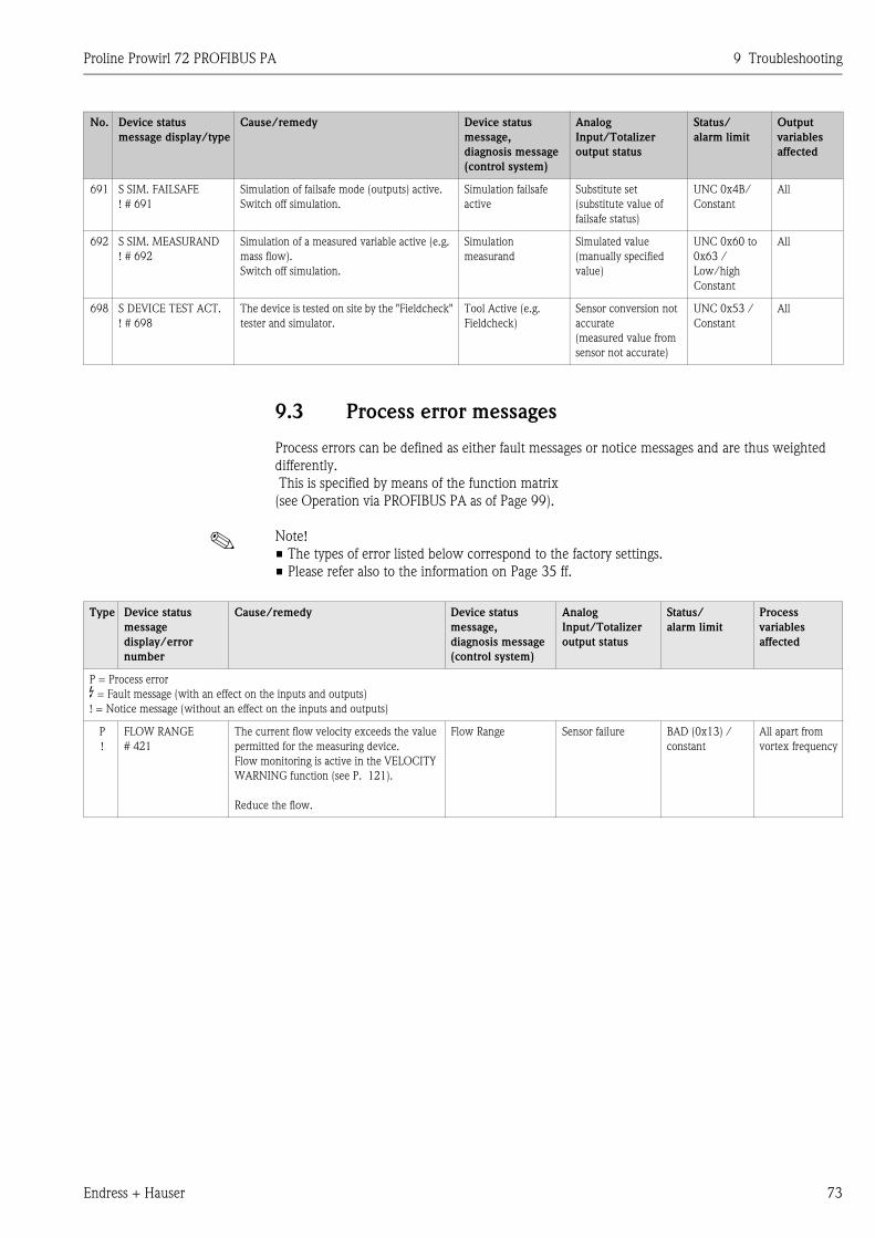
Proline Prowirl 72 PROFIBUS PA 9 Troubleshooting
Endress + Hauser 73
9.3 Process error messages
Process errors can be defined as either fault messages or notice messages and are thus weighted
differently.
This is specified by means of the function matrix
(see Operation via PROFIBUS PA as of Page 99).
! Note!
• The types of error listed below correspond to the factory settings.
• Please refer also to the information on Page 35 ff.
691 S SIM. FAILSAFE
! # 691
Simulation of failsafe mode (outputs) active.
Switch off simulation.
Simulation failsafe
active
Substitute set
(substitute value of
failsafe status)
UNC 0x4B/
Constant
All
692 S SIM. MEASURAND
! # 692
Simulation of a measured variable active (e.g.
mass flow).
Switch off simulation.
Simulation
measurand
Simulated value
(manually specified
value)
UNC 0x60 to
0x63 /
Low/high
Constant
All
698 S DEVICE TEST ACT.
! # 698
The device is tested on site by the "Fieldcheck"
tester and simulator.
Tool Active (e.g.
Fieldcheck)
Sensor conversion not
accurate
(measured value from
sensor not accurate)
UNC 0x53 /
Constant
All
No. Device status
message display/type
Cause/remedy Device status
message,
diagnosis message
(control system)
Analog
Input/Totalizer
output status
Status/
alarm limit
Output
variables
affected
Type Device status
message
display/error
number
Cause/remedy Device status
message,
diagnosis message
(control system)
Analog
Input/Totalizer
output status
Status/
alarm limit
Process
variables
affected
P = Process error
$ = Fault message (with an effect on the inputs and outputs)
! = Notice message (without an effect on the inputs and outputs)
P
!
FLOW RANGE
# 421
The current flow velocity exceeds the value
permitted for the measuring device.
Flow monitoring is active in the VELOCITY
WARNING function (see P. 121).
Reduce the flow.
Flow Range Sensor failure BAD (0x13) /
constant
All apart from
vortex frequency
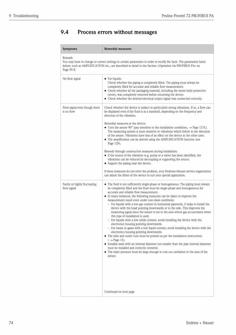
9 Troubleshooting Proline Prowirl 72 PROFIBUS PA
74 Endress + Hauser
9.4 Process errors without messages
Symptoms Remedial measures
Remark:
You may have to change or correct settings in certain parameters in order to rectify the fault. The parameters listed
below, such as AMPLIFICATION etc., are described in detail in the Section »Operation via PROFIBUS PA« on
Page 99 ff.
No flow signal • For liquids:
Check whether the piping is completely filled. The piping must always be
completely filled for accurate and reliable flow measurement.
• Check whether all the packaging material, including the meter body protective
covers, was completely removed before mounting the device.
• Check whether the desired electrical output signal was connected correctly.
Flow signal even though there
is no flow
Check whether the device is subject to particularly strong vibrations. If so, a flow can
be displayed even if the fluid is at a standstill, depending on the frequency and
direction of the vibration.
Remedial measures at the device:
• Turn the sensor 90° (pay attention to the installation conditions, → Page 12 ff.).
The measuring system is most sensitive to vibrations which follow in the direction
of the sensor. Vibrations have less of an effect on the device in the other axes.
• The amplification can be altered using the AMPLIFICATION function (see
Page 129).
Remedy through constructive measures during installation:
• If the source of the vibration (e.g. pump or a valve) has been identified, the
vibrations can be reduced by decoupling or supporting the source.
• Support the piping near the device.
If these measures do not solve the problem, your Endress+Hauser service organization
can adjust the filters of the device to suit your special application.
Faulty or highly fluctuating
flow signal
• The fluid is not sufficiently single-phase or homogeneous. The piping must always
be completely filled and the fluid must be single-phase and homogeneous for
accurate and reliable flow measurement.
• In many instances, the following measures can be taken to improve the
measurement result even under non-ideal conditions:
– For liquids with a low gas content in horizontal pipework, it helps to install the
device with the head pointing downwards or to the side. This improves the
measuring signal since the sensor is not in the area where gas accumulates when
this type of installation is used.
– For liquids with a low solids content, avoid installing the device with the
electronics housing pointing downwards.
– For steam or gases with a low liquid content, avoid installing the device with the
electronics housing pointing downwards.
• The inlet and outlet runs must be present as per the installation instructions
( → Page 15).
• Suitable seals with an internal diameter not smaller than the pipe internal diameter
must be installed and correctly centered.
• The static pressure must be large enough to rule out cavitation in the area of the
sensor.
Continued on next page
Proline Prowirl 72 PROFIBUS PA 9 Troubleshooting
Endress + Hauser 75
Faulty or highly fluctuating
flow signal (contd.)
• Check whether the correct fluid was selected in the APPLICATION function (see
Page 116). The setting in this function determines the filter settings and can thus
have an effect on the measuring range.
• Check whether the data for the K-factor on the nameplate match the data in the K-
FACTOR parameter (see Page 127).
• Check whether the device is installed correctly in the direction of flow.
• Check whether the nominal diameter of the mating pipe and the device match
(see Page 119).
• The flow must be in the measuring range of the device ( → Page 83). The start of
measuring range depends on the density and the viscosity of the fluid. Density and
viscosity depend on temperature. Density also depends on the process pressure in
the case of gases.
• Check whether the operating pressure is affected by pressure pulsations (e.g. from
piston pumps). The pulsations can affect vortex shedding if they have a frequency
similar to the vortex frequency.
• Check whether the correct engineering unit was selected for the flow or totalizer.
The fault cannot be rectified
or some other fault not
described above has occurred.
In these instances, please
contact your Endress+Hauser
service organization.
The following options are available for tackling problems of this nature:
Request the services of an Endress+Hauser service technician
If you contact our service organization to have a service technician sent out, please be
ready with the following information:
– A brief description of the error with information on the application.
– Nameplate specifications ( → Page 7 ff.): order code and serial number.
Return devices to Endress+Hauser
The procedures on Page 6 must be carried out before you return a measuring device
requiring repair or calibration to Endress+Hauser.
Always enclose a fully completed "Declaration of Contamination" form with the
flowmeter. A copy of the form can be found at the end of these Operating Instructions.
Replace transmitter electronics
Components in the electronics defective → Order spare part → Page 76
Symptoms Remedial measures
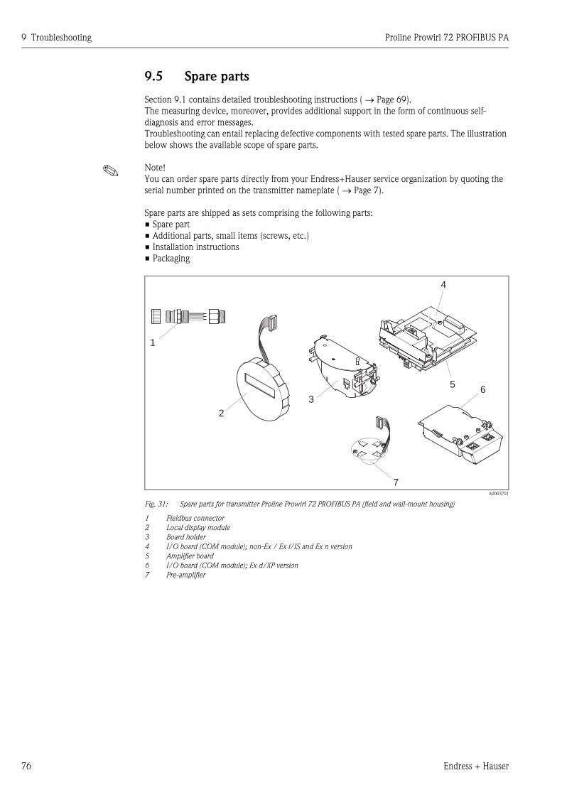
9 Troubleshooting Proline Prowirl 72 PROFIBUS PA
76 Endress + Hauser
9.5 Spare parts
Section 9.1 contains detailed troubleshooting instructions ( → Page 69).
The measuring device, moreover, provides additional support in the form of continuous self-
diagnosis and error messages.
Troubleshooting can entail replacing defective components with tested spare parts. The illustration
below shows the available scope of spare parts.
! Note!
You can order spare parts directly from your Endress+Hauser service organization by quoting the
serial number printed on the transmitter nameplate ( → Page 7).
Spare parts are shipped as sets comprising the following parts:
• Spare part
• Additional parts, small items (screws, etc.)
• Installation instructions
• Packaging
A0003791
Fig. 31: Spare parts for transmitter Proline Prowirl 72 PROFIBUS PA (field and wall-mount housing)
1 Fieldbus connector
2 Local display module
3 Board holder
4 I/O board (COM module); non-Ex / Ex i/IS and Ex n version
5 Amplifier board
6 I/O board (COM module); Ex d/XP version
7 Pre-amplifier
4
2
3
1
5
7
6
Proline Prowirl 72 PROFIBUS PA 9 Troubleshooting
Endress + Hauser 77
9.6 Installing and removing electronics boards
9.6.1 Non-Ex / Ex i/IS and Ex n version
! Note!
• When connecting Ex-certified devices, please refer to the notes and diagrams in the Ex-specific
supplement to these Operating Instructions.
• Risk of damaging electronic components (ESD protection).
Static electricity can damage electronic components or impair their operability. Use a workplace
with a grounded working surface, purpose-built for electrostatically sensitive devices!
" Caution!
Use only genuine Endress+Hauser parts.
Procedure when installing/removing electronics boards ( → Fig. 32)
1. Unscrew the cover (a) of the electronics compartment from the transmitter housing.
2. Remove the local display module (b) from the retaining rails (c).
3. Attach the left side of the local display module (b) to the right retaining rail (c) (this secures the
local display module).
4. Loosen the set screw (d) of the cover of the connection compartment (e) and fold down the
cover.
5. Disconnect the terminal connector (f) from the I/O board (COM module) (q).
6. Fold up the plastic cover (g).
7. Remove the signal cable connector (h) from the amplifier board (s) and release from the cable
retainer (i).
8. Remove the ribbon-cable connector (j) from the amplifier board (s) and release from the cable
retainer (k).
9. Detach the local display module (b) from the right retaining rail (c).
10. Fold down the plastic cover (g) again.
11. Release both screws (l) of the board holder (m).
12. Pull the board holder (m) out completely.
13. Press the side latches (n) of the board holder and separate the board holder (m) from the board
body (o).
14. Replace the I/O board (COM module) (q):
– Loosen the three fixing screws (p) of the I/O board (COM module).
– Remove the I/O board (COM module) (q) from the board body (o).
– Fix the new I/O board (COM module) onto the board body.
15. Replace the amplifier board (s):
– Loosen fixing screws (r) on the amplifier board.
– Remove the amplifier board (s) from the board body (o).
– Fix the new amplifier board onto the board body.
16. Installation is the reverse of the removal procedure.
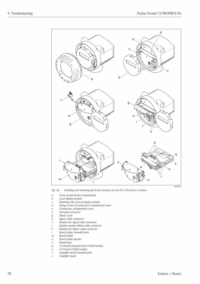
9 Troubleshooting Proline Prowirl 72 PROFIBUS PA
78 Endress + Hauser
A0003792
Fig. 32: Installing and removing electronics boards, non-Ex/Ex i/IS and Ex n version
a Cover of electronics compartment
b Local display module
c Retaining rails of local display module
d Fixing screws of connection compartment cover
e Connection compartment cover
f Terminal connector
g Plastic cover
h Signal cable connector
i Retainer for signal cable connector
j Display module ribbon-cable connector
k Retainer for ribbon-cable connector
l Board holder threaded joint
m Board holder
n Board holder latches
o Board body
p I/O board threaded joint (COM module)
q I/O board (COM module)
r Amplifier board threaded joint
s Amplifier board
a
c
c
e
b
d
g
h
j
k
i
ml
l
q
n
p
s
o
n
r
e
f
g
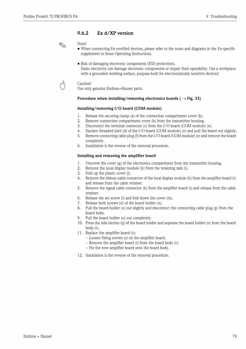
Proline Prowirl 72 PROFIBUS PA 9 Troubleshooting
Endress + Hauser 79
9.6.2 Ex d/XP version
! Note!
• When connecting Ex-certified devices, please refer to the notes and diagrams in the Ex-specific
supplement to these Operating Instructions.
• Risk of damaging electronic components (ESD protection).
Static electricity can damage electronic components or impair their operability. Use a workplace
with a grounded working surface, purpose-built for electrostatically sensitive devices!
" Caution!
Use only genuine Endress+Hauser parts.
Procedure when installing/removing electronics boards ( → Fig. 33)
Installing/removing I/O board (COM module)
1. Release the securing clamp (a) of the connection compartment cover (b).
2. Remove connection compartment cover (b) from the transmitter housing.
3. Disconnect the terminal connector (c) from the I/O board (COM module) (e).
4. Slacken threaded joint (d) of the I/O board (COM module) (e) and pull the board out slightly.
5. Remove connecting cable plug (f) from the I/O board (COM module) (e) and remove the board
completely.
6. Installation is the reverse of the removal procedure.
Installing and removing the amplifier board
1. Unscrew the cover (g) of the electronics compartment from the transmitter housing.
2. Remove the local display module (h) from the retaining rails (i).
3. Fold up the plastic cover (j).
4. Remove the ribbon-cable connector of the local display module (h) from the amplifier board (t)
and release from the cable retainer.
5. Remove the signal cable connector (k) from the amplifier board (t) and release from the cable
retainer.
6. Release the set screw (l) and fold down the cover (m).
7. Release both screws (n) of the board holder (o).
8. Pull the board holder (o) out slightly and disconnect the connecting cable plug (p) from the
board body.
9. Pull the board holder (o) out completely.
10. Press the side latches (q) of the board holder and separate the board holder (o) from the board
body (r).
11. Replace the amplifier board (t):
– Loosen fixing screws (s) on the amplifier board.
– Remove the amplifier board (t) from the board body (r).
– Fix the new amplifier board onto the board body.
12. Installation is the reverse of the removal procedure.
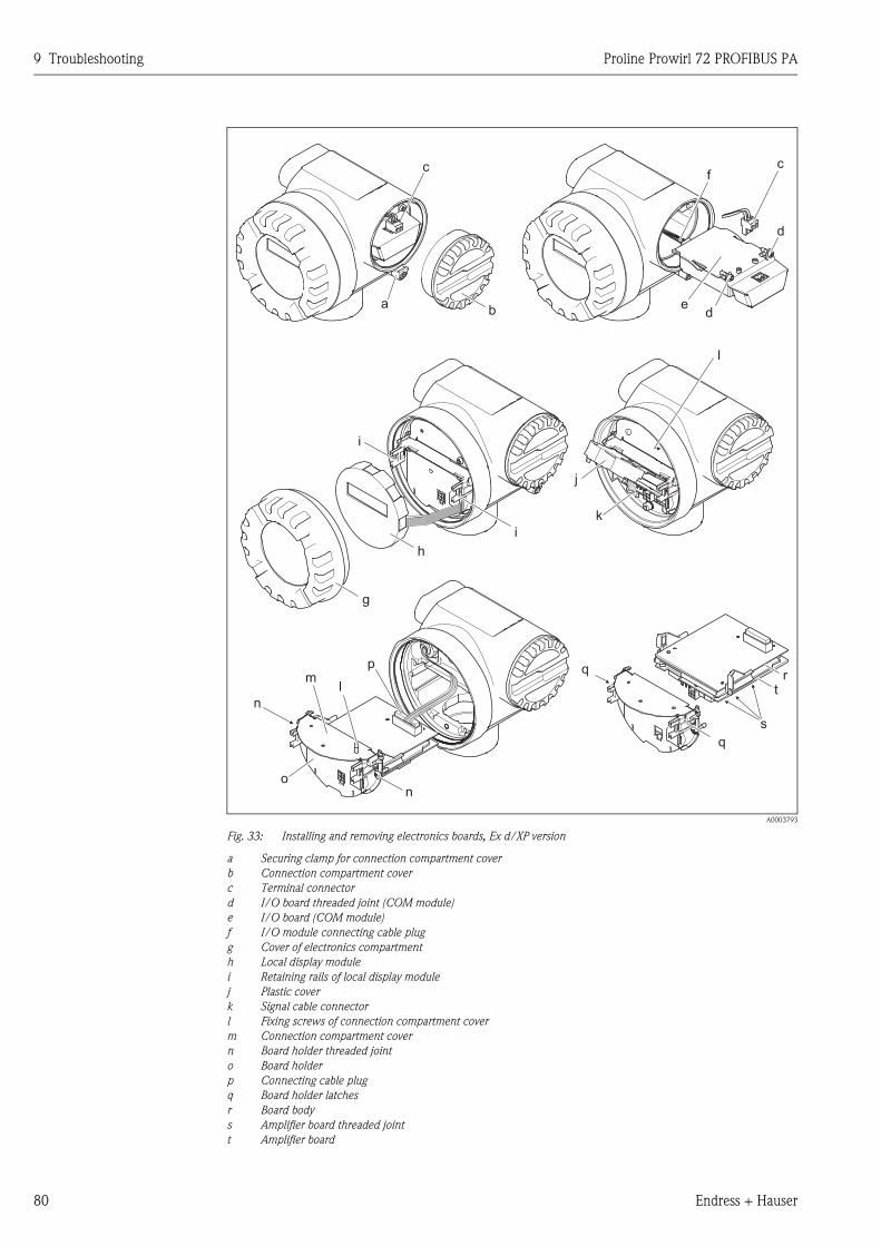
9 Troubleshooting Proline Prowirl 72 PROFIBUS PA
80 Endress + Hauser
A0003793
Fig. 33: Installing and removing electronics boards, Ex d/XP version
a Securing clamp for connection compartment cover
b Connection compartment cover
c Terminal connector
d I/O board threaded joint (COM module)
e I/O board (COM module)
f I/O module connecting cable plug
g Cover of electronics compartment
h Local display module
i Retaining rails of local display module
j Plastic cover
k Signal cable connector
l Fixing screws of connection compartment cover
m Connection compartment cover
n Board holder threaded joint
o Board holder
p Connecting cable plug
q Board holder latches
r Board body
s Amplifier board threaded joint
t Amplifier board
ba
c cf
d
de
g
h
i
i
j
l
l
p
n
n
o
mq
q
rt
s
k
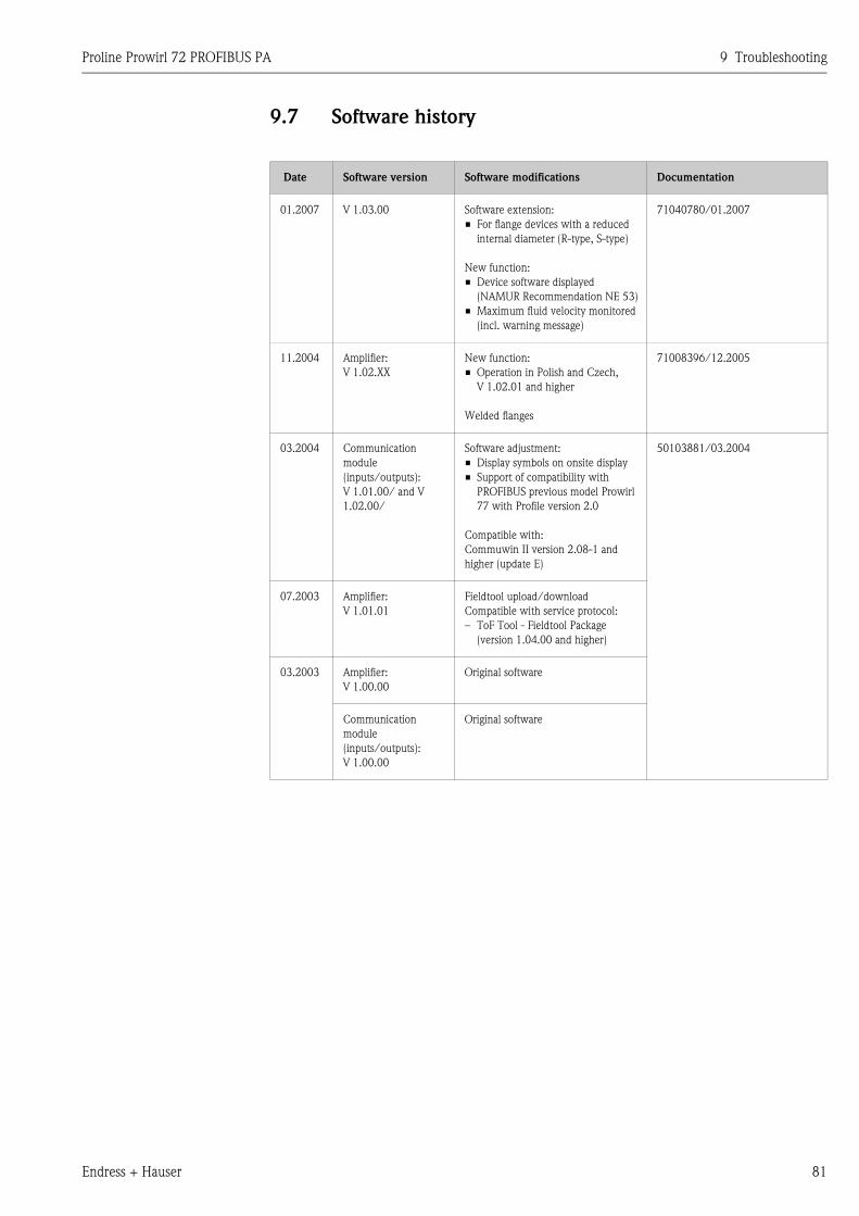
Proline Prowirl 72 PROFIBUS PA 9 Troubleshooting
Endress + Hauser 81
9.7 Software history
Date Software version Software modifications Documentation
01.2007 V 1.03.00 Software extension:
• For flange devices with a reduced
internal diameter (R-type, S-type)
New function:
• Device software displayed
(NAMUR Recommendation NE 53)
• Maximum fluid velocity monitored
(incl. warning message)
71040780/01.2007
11.2004 Amplifier:
V 1.02.XX
New function:
• Operation in Polish and Czech,
V 1.02.01 and higher
Welded flanges
71008396/12.2005
03.2004 Communication
module
(inputs/outputs):
V 1.01.00/ and V
1.02.00/
Software adjustment:
• Display symbols on onsite display
• Support of compatibility with
PROFIBUS previous model Prowirl
77 with Profile version 2.0
Compatible with:
Commuwin II version 2.08-1 and
higher (update E)
50103881/03.2004
07.2003 Amplifier:
V 1.01.01
Fieldtool upload/download
Compatible with service protocol:
– ToF Tool - Fieldtool Package
(version 1.04.00 and higher)
03.2003 Amplifier:
V 1.00.00
Original software
Communication
module
(inputs/outputs):
V 1.00.00
Original software

9 Troubleshooting Proline Prowirl 72 PROFIBUS PA
82 Endress + Hauser
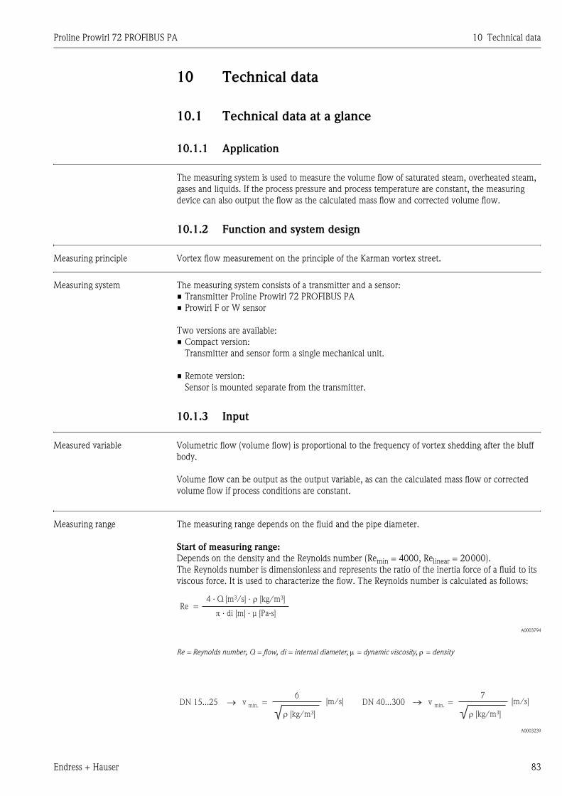
Proline Prowirl 72 PROFIBUS PA 10 Technical data
Endress + Hauser 83
10 Technical data
10.1 Technical data at a glance
10.1.1 Application
The measuring system is used to measure the volume flow of saturated steam, overheated steam,
gases and liquids. If the process pressure and process temperature are constant, the measuring
device can also output the flow as the calculated mass flow and corrected volume flow.
10.1.2 Function and system design
Measuring principle Vortex flow measurement on the principle of the Karman vortex street.
Measuring system The measuring system consists of a transmitter and a sensor:
• Transmitter Proline Prowirl 72 PROFIBUS PA
• Prowirl F or W sensor
Two versions are available:
• Compact version:
Transmitter and sensor form a single mechanical unit.
• Remote version:
Sensor is mounted separate from the transmitter.
10.1.3 Input
Measured variable Volumetric flow (volume flow) is proportional to the frequency of vortex shedding after the bluff
body.
Volume flow can be output as the output variable, as can the calculated mass flow or corrected
volume flow if process conditions are constant.
Measuring range The measuring range depends on the fluid and the pipe diameter.
Start of measuring range:
Depends on the density and the Reynolds number (Remin = 4000, Relinear = 20000).
The Reynolds number is dimensionless and represents the ratio of the inertia force of a fluid to its
viscous force. It is used to characterize the flow. The Reynolds number is calculated as follows:
A0003794
Re = Reynolds number, Q = flow, di = internal diameter, μ = dynamic viscosity, ρ = density
A0003239
Re =4 · Q · m³[m³/s] [kg/ ]�
di [m] · µ� · [Pa·s]
vDN 15...25 � =min.
6
� [kg/m³]
vDN 40...300 � =min.
7
� [kg/m³]
[m/s] [m/s]
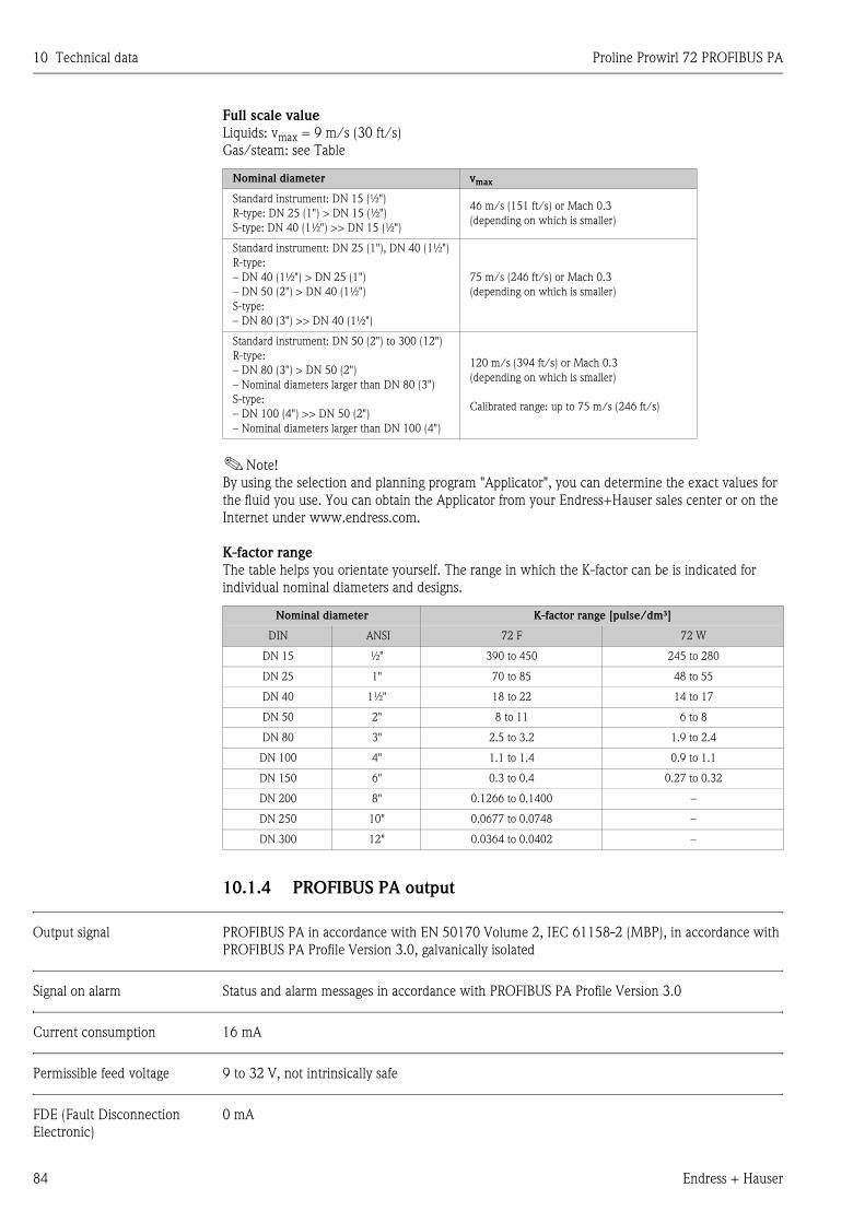
10 Technical data Proline Prowirl 72 PROFIBUS PA
84 Endress + Hauser
Full scale value
Liquids: vmax = 9 m/s (30 ft/s)
Gas/steam: see Table
!Note!
By using the selection and planning program "Applicator", you can determine the exact values for
the fluid you use. You can obtain the Applicator from your Endress+Hauser sales center or on the
Internet under www.endress.com.
K-factor range
The table helps you orientate yourself. The range in which the K-factor can be is indicated for
individual nominal diameters and designs.
10.1.4 PROFIBUS PA output
Output signal PROFIBUS PA in accordance with EN 50170 Volume 2, IEC 61158-2 (MBP), in accordance with
PROFIBUS PA Profile Version 3.0, galvanically isolated
Signal on alarm Status and alarm messages in accordance with PROFIBUS PA Profile Version 3.0
Current consumption 16 mA
Permissible feed voltage 9 to 32 V, not intrinsically safe
FDE (Fault Disconnection
Electronic)
0 mA
Nominal diameter vmax
Standard instrument: DN 15 (½")
R-type: DN 25 (1") > DN 15 (½")
S-type: DN 40 (1½") >> DN 15 (½")
46 m/s (151 ft/s) or Mach 0.3
(depending on which is smaller)
Standard instrument: DN 25 (1"), DN 40 (1½")
R-type:
– DN 40 (1½") > DN 25 (1")
– DN 50 (2") > DN 40 (1½")
S-type:
– DN 80 (3") >> DN 40 (1½")
75 m/s (246 ft/s) or Mach 0.3
(depending on which is smaller)
Standard instrument: DN 50 (2") to 300 (12")
R-type:
– DN 80 (3") > DN 50 (2")
– Nominal diameters larger than DN 80 (3")
S-type:
– DN 100 (4") >> DN 50 (2")
– Nominal diameters larger than DN 100 (4")
120 m/s (394 ft/s) or Mach 0.3
(depending on which is smaller)
Calibrated range: up to 75 m/s (246 ft/s)
Nominal diameter K-factor range [pulse/dm³]
DIN ANSI 72 F 72 W
DN 15 ½" 390 to 450 245 to 280
DN 25 1" 70 to 85 48 to 55
DN 40 1½" 18 to 22 14 to 17
DN 50 2" 8 to 11 6 to 8
DN 80 3" 2.5 to 3.2 1.9 to 2.4
DN 100 4" 1.1 to 1.4 0.9 to 1.1
DN 150 6" 0.3 to 0.4 0.27 to 0.32
DN 200 8" 0.1266 to 0.1400 –
DN 250 10" 0.0677 to 0.0748 –
DN 300 12" 0.0364 to 0.0402 –
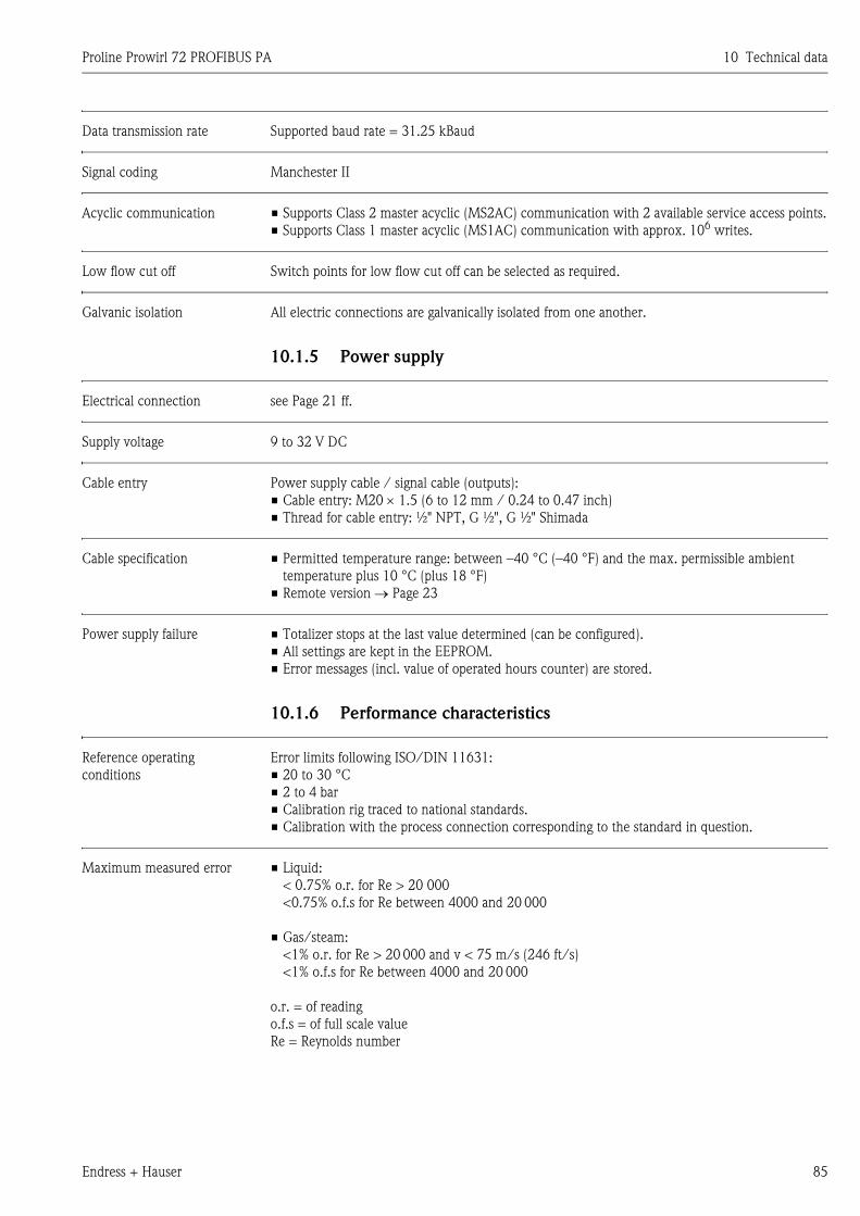
Proline Prowirl 72 PROFIBUS PA 10 Technical data
Endress + Hauser 85
Data transmission rate Supported baud rate = 31.25 kBaud
Signal coding Manchester II
Acyclic communication • Supports Class 2 master acyclic (MS2AC) communication with 2 available service access points.
• Supports Class 1 master acyclic (MS1AC) communication with approx. 106 writes.
Low flow cut off Switch points for low flow cut off can be selected as required.
Galvanic isolation All electric connections are galvanically isolated from one another.
10.1.5 Power supply
Electrical connection see Page 21 ff.
Supply voltage 9 to 32 V DC
Cable entry Power supply cable / signal cable (outputs):
• Cable entry: M20 × 1.5 (6 to 12 mm / 0.24 to 0.47 inch)
• Thread for cable entry: ½" NPT, G ½", G ½" Shimada
Cable specification • Permitted temperature range: between –40 °C (–40 °F) and the max. permissible ambient
temperature plus 10 °C (plus 18 °F)
• Remote version → Page 23
Power supply failure • Totalizer stops at the last value determined (can be configured).
• All settings are kept in the EEPROM.
• Error messages (incl. value of operated hours counter) are stored.
10.1.6 Performance characteristics
Reference operating
conditions
Error limits following ISO/DIN 11631:
• 20 to 30 °C
• 2 to 4 bar
• Calibration rig traced to national standards.
• Calibration with the process connection corresponding to the standard in question.
Maximum measured error • Liquid:
< 0.75% o.r. for Re > 20 000
<0.75% o.f.s for Re between 4000 and 20 000
• Gas/steam:
<1% o.r. for Re > 20 000 and v < 75 m/s (246 ft/s)
<1% o.f.s for Re between 4000 and 20 000
o.r. = of reading
o.f.s = of full scale value
Re = Reynolds number
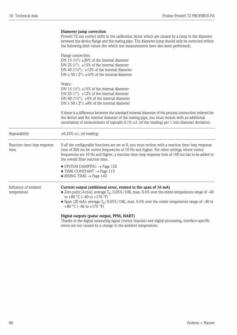
10 Technical data Proline Prowirl 72 PROFIBUS PA
86 Endress + Hauser
Diameter jump correction
Prowirl 72 can correct shifts in the calibration factor which are caused by a jump in the diameter
between the device flange and the mating pipe. The diameter jump should only be corrected within
the following limit values (for which test measurements have also been performed).
Flange connection:
DN 15 (½"): ±20% of the internal diameter
DN 25 (1"): ±15% of the internal diameter
DN 40 (1½"): ±12% of the internal diameter
DN ≥ 50 ( 2"): ±10% of the internal diameter
Wafer:
DN 15 (½"): ±15% of the internal diameter
DN 25 (1"): ±12% of the internal diameter
DN 40 (1½"): ±9% of the internal diameter
DN ≥ 50 ( 2"): ±8% of the internal diameter
If there is a difference between the standard internal diameter of the process connection ordered for
the device and the internal diameter of the mating pipe, you must reckon with an additional
uncertainty of measurement of typically 0.1% o.f. (of the reading) per 1 mm diameter deviation.
Repeatability ±0.25% o.r. (of reading)
Reaction time/step response
time
If all the configurable functions are set to 0, you must reckon with a reaction time/step response
time of 200 ms for vortex frequencies of 10 Hz and higher. For other settings where vortex
frequencies are 10 Hz and higher, a reaction time/step response time of 100 ms has to be added to
the overall filter reaction time.
• SYSTEM DAMPING → Page 122
• TIME CONSTANT → Page 113
• RISING TIME → Page 143
Influence of ambient
temperature
Current output (additional error, related to the span of 16 mA)
• Zero point (4 mA): average Tk: 0.05%/10K, max. 0.6% over the entire temperature range of –40
to +80 °C (–40 to +176 °F)
• Span (20 mA): average Tk: 0.05%/10K, max. 0.6% over the entire temperature range of –40 to
+80 °C (–40 to +176 °F)
Digital outputs (pulse output, PFM, HART)
Thanks to the digital measuring signal (vortex impulse) and digital processing, interface-specific
errors are not caused by a change in the ambient temperature.
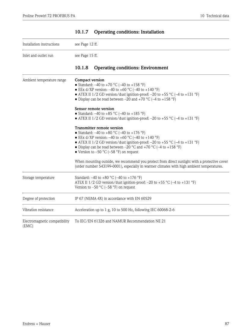
Proline Prowirl 72 PROFIBUS PA 10 Technical data
Endress + Hauser 87
10.1.7 Operating conditions: Installation
Installation instructions see Page 12 ff.
Inlet and outlet run see Page 15 ff.
10.1.8 Operating conditions: Environment
Ambient temperature range Compact version
• Standard: –40 to +70 °C (–40 to +158 °F)
• EEx d/XP version: –40 to +60 °C (–40 to +140 °F)
• ATEX II 1/2 GD version/dust ignition-proof: –20 to +55 °C (–4 to +131 °F)
• Display can be read between –20 and +70 °C (–4 to +158 °F)
Sensor remote version
• Standard: –40 to +85 °C (–40 to +185 °F)
• ATEX II 1/2 GD version/dust ignition-proof: –20 to +55 °C (–4 to +131 °F)
Transmitter remote version
• Standard: –40 to +80 °C (–40 to +176 °F)
• EEx d/XP version: –40 to +60 °C (–40 to +140 °F)
• ATEX II 1/2 GD version/dust ignition-proof: –20 to +55 °C (–4 to +131 °F)
• Display can be read between –20 °C and +70 °C (–4 to +158 °F)
• Version to –50 °C (–58 °F) on request
When mounting outside, we recommend you protect from direct sunlight with a protective cover
(order number 543199-0001), especially in warmer climates with high ambient temperatures.
Storage temperature Standard: –40 to +80 °C (–40 to +176 °F)
ATEX II 1/2 GD version/dust ignition-proof: –20 to +55 °C (–4 to +131 °F)
Version to –50 °C (–58 °F) on request
Degree of protection IP 67 (NEMA 4X) in accordance with EN 60529
Vibration resistance Acceleration up to 1 g, 10 to 500 Hz, following IEC 60068-2-6
Electromagnetic compatibility
(EMC)
To IEC/EN 61326 and NAMUR Recommendation NE 21
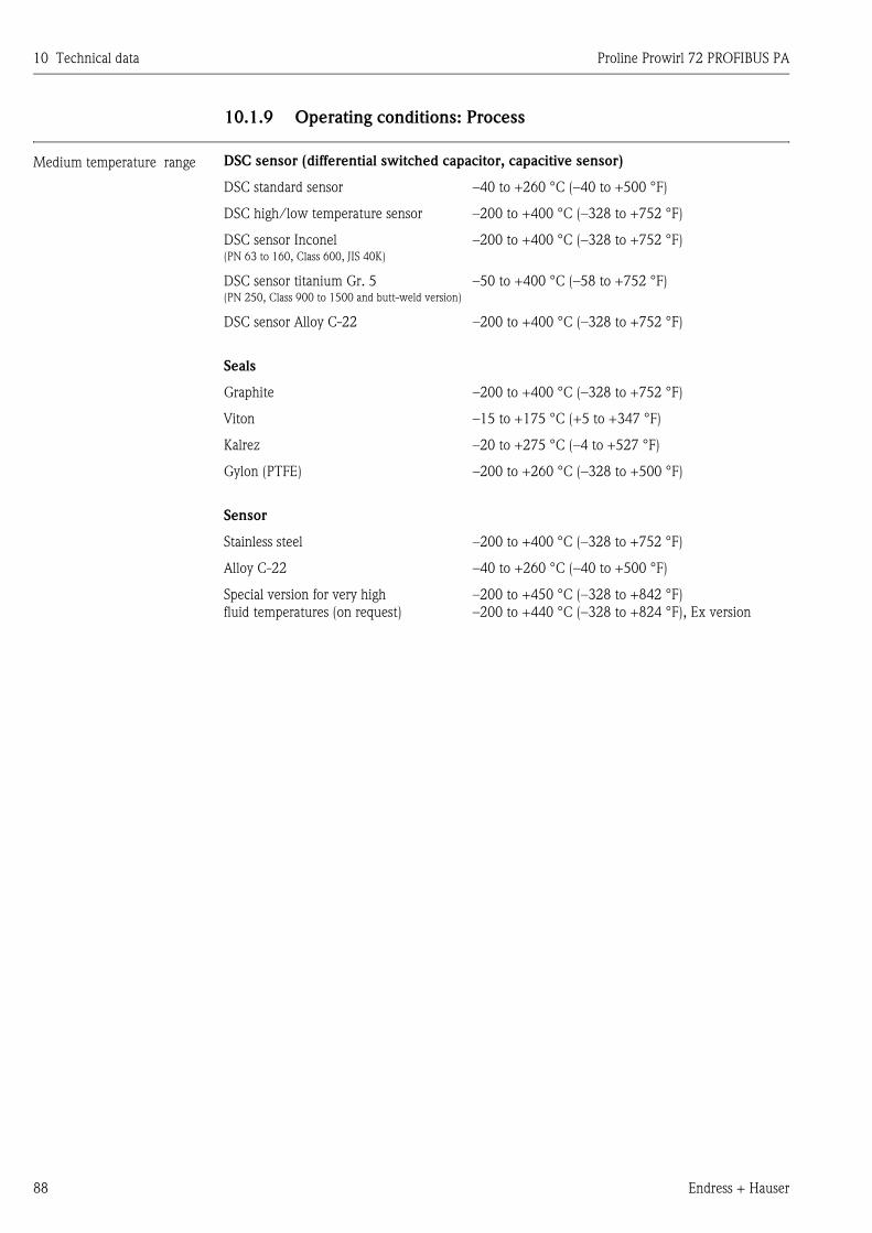
10 Technical data Proline Prowirl 72 PROFIBUS PA
88 Endress + Hauser
10.1.9 Operating conditions: Process
Medium temperature range DSC sensor (differential switched capacitor, capacitive sensor)
DSC standard sensor –40 to +260 °C (–40 to +500 °F)
DSC high/low temperature sensor –200 to +400 °C (–328 to +752 °F)
DSC sensor Inconel(PN 63 to 160, Class 600, JIS 40K)
–200 to +400 °C (–328 to +752 °F)
DSC sensor titanium Gr. 5 (PN 250, Class 900 to 1500 and butt-weld version)
–50 to +400 °C (–58 to +752 °F)
DSC sensor Alloy C-22 –200 to +400 °C (–328 to +752 °F)
Seals
Graphite –200 to +400 °C (–328 to +752 °F)
Viton –15 to +175 °C (+5 to +347 °F)
Kalrez –20 to +275 °C (–4 to +527 °F)
Gylon (PTFE) –200 to +260 °C (–328 to +500 °F)
Sensor
Stainless steel –200 to +400 °C (–328 to +752 °F)
Alloy C-22 –40 to +260 °C (–40 to +500 °F)
Special version for very high
fluid temperatures (on request)
–200 to +450 °C (–328 to +842 °F)
–200 to +440 °C (–328 to +824 °F), Ex version
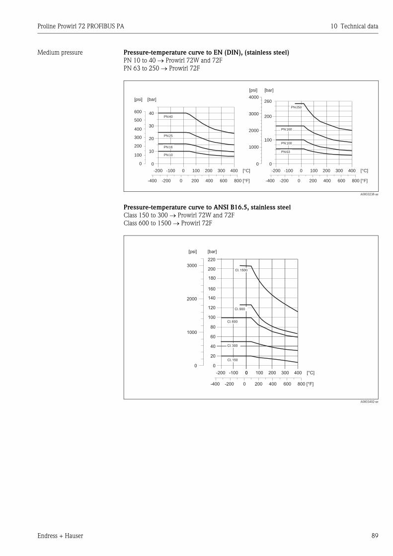
Proline Prowirl 72 PROFIBUS PA 10 Technical data
Endress + Hauser 89
Medium pressure Pressure-temperature curve to EN (DIN), (stainless steel)
PN 10 to 40 → Prowirl 72W and 72F
PN 63 to 250 → Prowirl 72F
A0003238-ae
Pressure-temperature curve to ANSI B16.5, stainless steel
Class 150 to 300 → Prowirl 72W and 72F
Class 600 to 1500 → Prowirl 72F
A0003402-ae
PN 40
PN 25
PN 16
PN 10
PN 250
PN 160
PN 100
PN 63
-200 -100 0 100 200 300 400 [°C]
00
100
200
10
20
30
40
[bar]
300
400
500
600
[psi]
-400 -200 0 800 [°F]200 600400
-200 -100 0 100 200 300 400 [°C]
-400 -200 0 800 [°F]200 600400
2000
3000
4000
00
1000
100
[bar][psi]
200
260
Cl. 1500
Cl. 900
Cl. 600
Cl. 300
Cl. 150
00
20
40
60
80
100
120
[bar]
200
140
160
180
220
1000
2000
3000
[psi]
-200 -100 0 100 200 300 400 [°C]0
-400 -200 0 800 [°F]200 600400
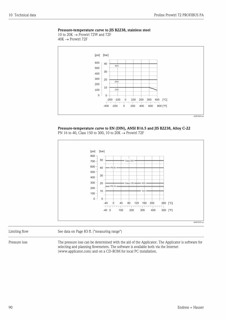
10 Technical data Proline Prowirl 72 PROFIBUS PA
90 Endress + Hauser
Pressure-temperature curve to JIS B2238, stainless steel
10 to 20K → Prowirl 72W and 72F
40K → Prowirl 72F
A0003404-ae
Pressure-temperature curve to EN (DIN), ANSI B16.5 and JIS B2238, Alloy C-22
PN 16 to 40, Class 150 to 300, 10 to 20K → Prowirl 72F
A0003395-ae
Limiting flow See data on Page 83 ff. ("measuring range")
Pressure loss The pressure loss can be determined with the aid of the Applicator. The Applicator is software for
selecting and planning flowmeters. The software is available both via the Internet
(www.applicator.com) and on a CD-ROM for local PC installation.
40 K
20 K
10 K
00
100
200
10
20
30
40
[bar]
300
400
500
600
[psi]
-200 -100 0 100 200 300 400 [°C]
-400 -200 0 800 [°F]200 600400
PN 40
PN 16
Class 300
Class 150 20 K
10 K
0
10
20
30
40
50
[bar][psi]
200
100
400
300
500
600
700
800
0
-40 0 40 80 120 160 200 260 [°C]
500 [°F]0-40 100 200 300 400
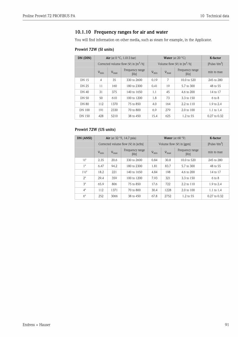
Proline Prowirl 72 PROFIBUS PA 10 Technical data
Endress + Hauser 91
10.1.10 Frequency ranges for air and water
You will find information on other media, such as steam for example, in the Applicator.
Prowirl 72W (SI units)
Prowirl 72W (US units)
DN (DIN) Air (at 0 °C, 1.013 bar) Water (at 20 °C) K-factor
Corrected volume flow (e) in [m3/h] Volume flow (e) in [m3/h] [Pulse/dm3]
emin emaxFrequency range
[Hz]emin emax
Frequency range
[Hz]min to max
DN 15 4 35 330 to 2600 0.19 7 10.0 to 520 245 to 280
DN 25 11 160 180 to 2300 0.41 19 5.7 to 300 48 to 55
DN 40 31 375 140 to 1650 1.1 45 4.6 to 200 14 to 17
DN 50 50 610 100 to 1200 1.8 73 3.3 to 150 6 to 8
DN 80 112 1370 75 to 850 4.0 164 2.2 to 110 1.9 to 2.4
DN 100 191 2330 70 to 800 6.9 279 2.0 to 100 1.1 to 1.4
DN 150 428 5210 38 to 450 15.4 625 1.2 to 55 0.27 to 0.32
DN (ANSI) Air (at 32 °F, 14.7 psia) Water (at 68 °F) K-factor
Corrected volume flow (e) in [scfm] Volume flow (e) in [gpm] [Pulse/dm3]
emin emaxFrequency range
[Hz]emin emax
Frequency range
[Hz]min to max
½" 2.35 20.6 330 to 2600 0.84 30.8 10.0 to 520 245 to 280
1" 6.47 94.2 180 to 2300 1.81 83.7 5.7 to 300 48 to 55
1½" 18.2 221 140 to 1650 4.84 198 4.6 to 200 14 to 17
2" 29.4 359 100 to 1200 7.93 321 3.3 to 150 6 to 8
3" 65.9 806 75 to 850 17.6 722 2.2 to 110 1.9 to 2.4
4" 112 1371 70 to 800 30.4 1228 2.0 to 100 1.1 to 1.4
6" 252 3066 38 to 450 67.8 2752 1.2 to 55 0.27 to 0.32
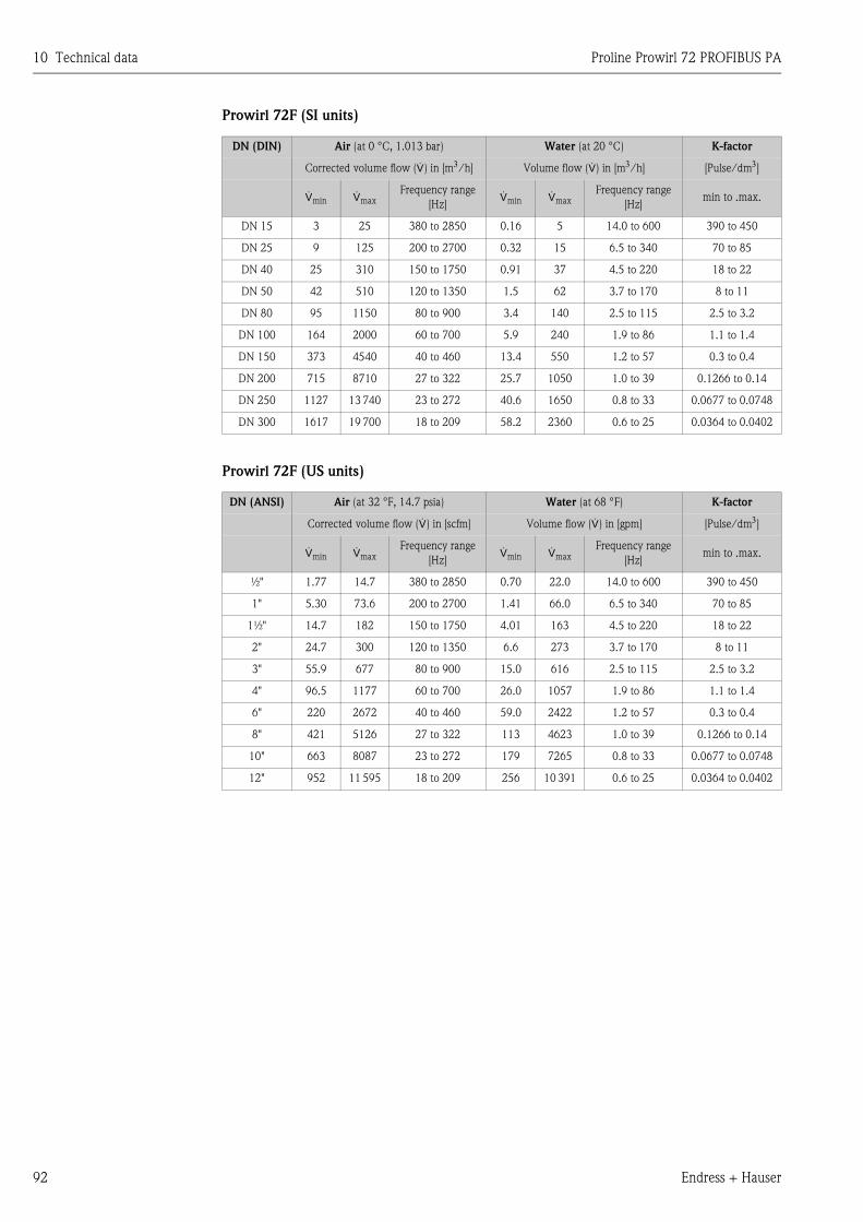
10 Technical data Proline Prowirl 72 PROFIBUS PA
92 Endress + Hauser
Prowirl 72F (SI units)
Prowirl 72F (US units)
DN (DIN) Air (at 0 °C, 1.013 bar) Water (at 20 °C) K-factor
Corrected volume flow (e) in [m3/h] Volume flow (e) in [m3/h] [Pulse/dm3]
emin emaxFrequency range
[Hz]emin emax
Frequency range
[Hz]min to .max.
DN 15 3 25 380 to 2850 0.16 5 14.0 to 600 390 to 450
DN 25 9 125 200 to 2700 0.32 15 6.5 to 340 70 to 85
DN 40 25 310 150 to 1750 0.91 37 4.5 to 220 18 to 22
DN 50 42 510 120 to 1350 1.5 62 3.7 to 170 8 to 11
DN 80 95 1150 80 to 900 3.4 140 2.5 to 115 2.5 to 3.2
DN 100 164 2000 60 to 700 5.9 240 1.9 to 86 1.1 to 1.4
DN 150 373 4540 40 to 460 13.4 550 1.2 to 57 0.3 to 0.4
DN 200 715 8710 27 to 322 25.7 1050 1.0 to 39 0.1266 to 0.14
DN 250 1127 13 740 23 to 272 40.6 1650 0.8 to 33 0.0677 to 0.0748
DN 300 1617 19 700 18 to 209 58.2 2360 0.6 to 25 0.0364 to 0.0402
DN (ANSI) Air (at 32 °F, 14.7 psia) Water (at 68 °F) K-factor
Corrected volume flow (e) in [scfm] Volume flow (e) in [gpm] [Pulse/dm3]
emin emaxFrequency range
[Hz]emin emax
Frequency range
[Hz]min to .max.
½" 1.77 14.7 380 to 2850 0.70 22.0 14.0 to 600 390 to 450
1" 5.30 73.6 200 to 2700 1.41 66.0 6.5 to 340 70 to 85
1½" 14.7 182 150 to 1750 4.01 163 4.5 to 220 18 to 22
2" 24.7 300 120 to 1350 6.6 273 3.7 to 170 8 to 11
3" 55.9 677 80 to 900 15.0 616 2.5 to 115 2.5 to 3.2
4" 96.5 1177 60 to 700 26.0 1057 1.9 to 86 1.1 to 1.4
6" 220 2672 40 to 460 59.0 2422 1.2 to 57 0.3 to 0.4
8" 421 5126 27 to 322 113 4623 1.0 to 39 0.1266 to 0.14
10" 663 8087 23 to 272 179 7265 0.8 to 33 0.0677 to 0.0748
12" 952 11 595 18 to 209 256 10 391 0.6 to 25 0.0364 to 0.0402
Proline Prowirl 72 PROFIBUS PA 10 Technical data
Endress + Hauser 93
10.1.11 Mechanical construction
Design, dimensions See Technical Information TI070D/06/en
Weight See Technical Information TI070D/06/en
Material Transmitter housing:
• Powder-coated die-cast aluminum AlSi10Mg
– In accordance with EN 1706/EN AC-43400 (EEx d/XP version: cast aluminum EN 1706/EN
AC-43000)
Sensor:
• Flanged version:
– Stainless steel, A351-CF3M (1.4404), in conformity with NACE MR0175-2003 and MR0103-
2003
– Pressure ratings PN 250, Class 900 to 1500 and butt-weld version 1.4571 (316Ti; UNS
S31635); in conformity with NACE MR0175-2003 and MR0103-2003
• Alloy C-22 version
– Alloy C-22 2.4602 (A 494-CX2MW/N 26022); in conformity with NACE MR0175-2003 and
MR0103-2003
• Wafer version
– Stainless steel, A351-CF3M (1.4404), in conformity with NACE MR0175-2003 and MR0103-
2003
Flanges:
• EN (DIN)
– Stainless steel, A351-CF3M (1.4404), in conformity with NACE MR0175-2003 and MR0103-
2003
– DN 15 to 150 with pressure ratings to PN 40 and all devices with integrated nominal diameter
reduction (R-type, S-type): construction with weld-on flanges made of 1.4404 (AISI 316L).
PN 63 to 160, nominal diameters DN 200 to 300: fully cast construction A351-CF3M (1.4404
(AISI 316L)), in conformity with NACE MR0175-2003 and MR0103-2003
– Pressure rating PN 250 1.4571 (316Ti, UNS S31635); in conformity with NACE MR0175-
2003 and MR0103-2003
• ANSI and JIS
– Stainless steel, A351-CF3M, in conformity with NACE MR0175-2003 and MR0103-2003
– ½ to 6" with pressure ratings to Class 300 and DN 15 to 150 with pressure ratings to 20K and
all devices with integrated nominal diameter reduction (R-type, S-type): construction with
weld-on flanges made of 316/316L, in conformity with NACE MR0175-2003 and MR0103-
2003.
Class 600, DN 15 to 150 with pressure rating 40K, nominal diameters 8 to 12": fully cast
construction A351-CF3M; in conformity with NACE MR0175-2003 and MR0103-2003
– Pressure ratings Class 900 to 1500: 316/316L; in conformity with NACE MR0175-2003 and
MR0103-2003
• Alloy C-22 version (EN/DIN/ANSI/JIS)
– Alloy C-22 2.4602 (A 494-CX2MW/N 26022); in conformity with NACE MR0175-2003 and
MR0103-2003
DSC sensor (differential switched capacitor; capacitive sensor):
• Wetted parts (marked as "wet" on the DSC sensor flange).
– Standard for pressure ratings up to PN 40, Class 300, JIS 20K:
Stainless steel 1.4435 (316L), in conformity with NACE MR0175-2003 and MR0103-2003
– Pressure ratings PN 63 to 160, Class 600, 40K:
Inconel 2.4668/N 07718 (B637) (Inconel 718), in conformity with NACE MR0175-2003 and
MR0103-2003
– Pressure ratings PN 250, Class 900 to 1500 and butt-weld version:
titanium Gr. 5 (B-348; UNS R50250; 3.7165)
– Alloy C-22 sensor:
Alloy C-22, 2.4602/N 06022; in conformity with NACE MR0175-2003 and MR0103-2003
10 Technical data Proline Prowirl 72 PROFIBUS PA
94 Endress + Hauser
Non-wetted parts:
• Stainless steel 1.4301 (304)
Pipe stand:
• Stainless steel, 1.4308 (CF8)
• Pressure ratings PN 250, Class 900 to 1500 and butt-weld version: 1.4305 (303)
Seals:
• Graphite:
– Pressure rating PN 10 to 40, Class 150 to 300, JIS 10 to 20K: Sigraflex Foil Z (BAM-tested for
oxygen applications)
– Pressure rating PN 63 to 160, Class 600, JIS 40K: Sigraflex HochdruckTM with smooth sheet
metal insert made of 316(L) (BAM-tested for oxygen applications, "high quality in terms of TA
Luft (German Clean Air Act)"
– Pressure rating PN 250, Class 900 to 1500: Grafoil with 316 perforated metal insert
• Viton
• Kalrez 6375
• Gylon (PTFE) 3504 (BAM-tested for oxygen applications, "high quality in terms of TA Luft
(German Clean Air Act)")
10.1.12 Human interface
Display elements • Liquid crystal display, two-line plain text display, with 16 characters each.
• Custom configurations for presenting different measured value and status variables
Operating elements No local operating elements, remote operation possible.
Remote operation Operation via:
• PROFIBUS PA
• ToF Tool - Fieldtool Package (software package from Endress+Hauser for complete configuration,
commissioning and diagnosis)
10.1.13 Certificates and approvals
CE approval → Page 9
C-tick mark → Page 9
Ex approval More information on the Ex approvals can be found in the separate Ex documentation.
Pressure measuring device
approval
All measuring devices, including those with a nominal diameter smaller than or equal to DN 25,
correspond to Article 3(3) of the EC Directive 97/23/EC (Pressure Equipment Directive) and have
been designed and manufactured according to good engineering practice. For nominal diameters
greater than DN 25 (depending on the medium and process pressure), there are additional optional
approvals according to category II/III.
Certification PROFIBUS PA The Prowirl 72 flowmeter has successfully passed all the test procedures implemented and has been
certified and registered by the PNO (PROFIBUS User Organization). The flowmeter thus meets all
the requirements of the specifications listed below:
• Certified to PROFIBUS PA Profile Version 3.0, device certification number: available upon request
• The device may also be operated using certified devices from other manufacturers
(interoperability).
Proline Prowirl 72 PROFIBUS PA 10 Technical data
Endress + Hauser 95
Other standards and
guidelines
• EN 60529: Degrees of protection by housing (IP code)
• EN 61010-1: Protection measures for electrical equipment for measurement, control, regulation
and laboratory procedures
• IEC/EN 61326: Electromagnetic compatibility (EMC requirements)
• NAMUR NE 21: Electromagnetic compatibility (EMC) of industrial process and laboratory control
equipment
• NAMUR NE 53: Software of field devices and signal-processing devices with digital electronics.
• NACE Standard MR0103-2003: Standard Material Requirements - Materials Resistant to Sulfide
Stress Cracking in Corrosive Petroleum Refining Environments
• NACE Standard MR0175-2003: Standard Material Requirements - Sulfide Stress Cracking
Resistant Metallic Materials for Oilfield Equipment
• VDI 2643: Measurement of volume flow by means of vortex flowmeters
• ANSI/ISA-S82.01: Safety Standard for Electrical and Electronic Test, Measuring, Controlling and
related Equipment - General Requirements. Pollution degree 2, Installation Category II.
• CAN/CSA-C22.2 No. 1010.1-92: Safety Standard for Electrical Equipment for Measurement and
Control and Laboratory Use. Pollution degree 2, Installation Category II.
Ordering information Your Endress+Hauser service organization can provide detailed ordering information and
information on the order codes on request.
10.1.14 Accessories
Various accessories, which can be ordered separately from Endress+Hauser, are available for the
transmitter and the sensor (see Page 67). Your Endress+Hauser service organization can provide
detailed information on the order codes of your choice.
10.1.15 Documentation
• Flow measuring technology (FA005D/06/en)
• Technical Information Proline Prowirl 72F, 72W, 73F, 73W (TI070/06/en)
• Related Ex-documentation: ATEX, FM, CSA etc.
• Information on Pressure Equipment Directive for Proline Prowirl 72/73 (SD072D/06/en)
• Functional safety manual (Safety Integrity Level)
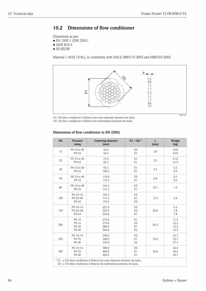
10 Technical data Proline Prowirl 72 PROFIBUS PA
96 Endress + Hauser
10.2 Dimensions of flow conditioner
Dimensions as per:
• EN 1092-1 (DIN 2501)
• ANSI B16.5
• JIS B2238
Material 1.4435 (316L), in conformity with NACE MR0175-2003 and MR0103-2003
A0001941
D1: The flow conditioner is fitted at the outer diameter between the bolts.
D2: The flow conditioner is fitted at the indentations between the bolts.
Dimensions of flow conditioner to EN (DIN)
DN Pressure
rating
Centering diameter
[mm]
D1 / D2 * s
[mm]
Weight
[kg]
15PN 10 to 40
PN 63
54.3
64.3
D2
D12.0
0.04
0.05
25PN 10 to 40
PN 63
74.3
85.3
D1
D13.5
0.12
0.15
40PN 10 to 40
PN 63
95.3
106.3
D1
D15.3
0.3
0.4
50PN 10 to 40
PN 63
110.0
116.3
D2
D16.8
0.5
0.6
80PN 10 to 40
PN 63
145.3
151.3
D2
D110.1 1.4
100
PN 10/16
PN 25/40
PN 63
165.3
171.3
176.5
D2
D1
D2
13.3 2.4
150
PN 10/16
PN 25/40
PN 63
221.0
227.0
252.0
D2
D2
D1
20.0
6.3
7.8
7.8
200
PN 10
PN 16
PN 25
PN 40
274.0
274.0
280.0
294.0
D1
D2
D1
D2
26.3
11.5
12.3
12.3
15.9
250
PN 10/16
PN 25
PN 40
330.0
340.0
355.0
D2
D1
D2
33.0
25.7
25.7
27.5
300
PN 10/16
PN 25
PN 40
380.0
404.0
420.0
D2
D1
D1
39.6
36.4
36.4
44.7
* D1 → The flow conditioner is fitted at the outer diameter between the bolts.
D2 → The flow conditioner is fitted at the indentations between the bolts.
sD2
D1
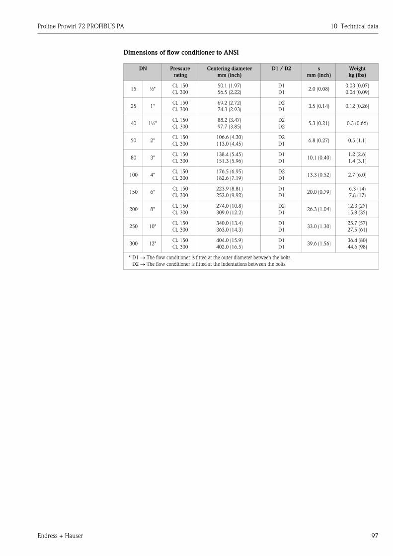
Proline Prowirl 72 PROFIBUS PA 10 Technical data
Endress + Hauser 97
Dimensions of flow conditioner to ANSI
DN Pressure
rating
Centering diameter
mm (inch)
D1 / D2 s
mm (inch)
Weight
kg (lbs)
15 ½"Cl. 150
Cl. 300
50.1 (1.97)
56.5 (2.22)
D1
D12.0 (0.08)
0.03 (0.07)
0.04 (0.09)
25 1"Cl. 150
Cl. 300
69.2 (2.72)
74.3 (2.93)
D2
D13.5 (0.14) 0.12 (0.26)
40 1½"Cl. 150
Cl. 300
88.2 (3.47)
97.7 (3.85)
D2
D25.3 (0.21) 0.3 (0.66)
50 2"Cl. 150
Cl. 300
106.6 (4.20)
113.0 (4.45)
D2
D16.8 (0.27) 0.5 (1.1)
80 3"Cl. 150
Cl. 300
138.4 (5.45)
151.3 (5.96)
D1
D110.1 (0.40)
1.2 (2.6)
1.4 (3.1)
100 4"Cl. 150
Cl. 300
176.5 (6.95)
182.6 (7.19)
D2
D113.3 (0.52) 2.7 (6.0)
150 6"Cl. 150
Cl. 300
223.9 (8.81)
252.0 (9.92)
D1
D120.0 (0.79)
6.3 (14)
7.8 (17)
200 8"Cl. 150
Cl. 300
274.0 (10.8)
309.0 (12.2)
D2
D126.3 (1.04)
12.3 (27)
15.8 (35)
250 10"Cl. 150
Cl. 300
340.0 (13.4)
363.0 (14.3)
D1
D133.0 (1.30)
25.7 (57)
27.5 (61)
300 12"Cl. 150
Cl. 300
404.0 (15.9)
402.0 (16.5)
D1
D139.6 (1.56)
36.4 (80)
44.6 (98)
* D1 → The flow conditioner is fitted at the outer diameter between the bolts.
D2 → The flow conditioner is fitted at the indentations between the bolts.
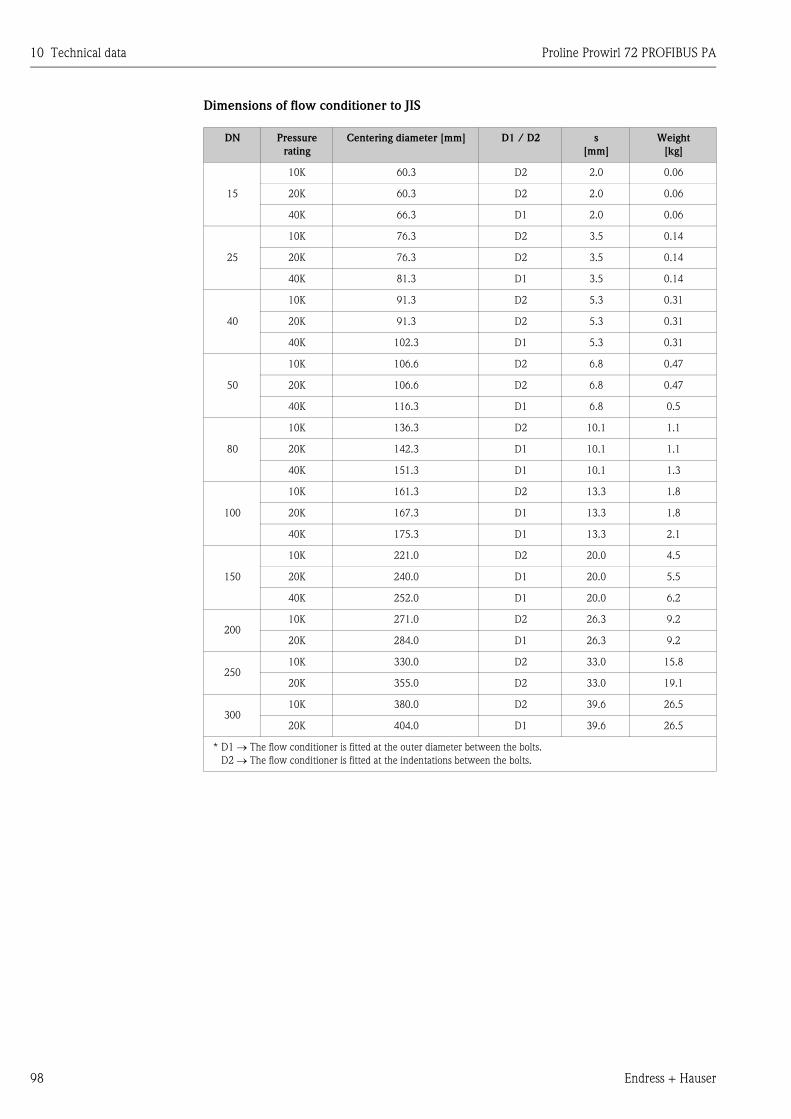
10 Technical data Proline Prowirl 72 PROFIBUS PA
98 Endress + Hauser
Dimensions of flow conditioner to JIS
DN Pressure
rating
Centering diameter [mm] D1 / D2 s
[mm]
Weight
[kg]
15
10K 60.3 D2 2.0 0.06
20K 60.3 D2 2.0 0.06
40K 66.3 D1 2.0 0.06
25
10K 76.3 D2 3.5 0.14
20K 76.3 D2 3.5 0.14
40K 81.3 D1 3.5 0.14
40
10K 91.3 D2 5.3 0.31
20K 91.3 D2 5.3 0.31
40K 102.3 D1 5.3 0.31
50
10K 106.6 D2 6.8 0.47
20K 106.6 D2 6.8 0.47
40K 116.3 D1 6.8 0.5
80
10K 136.3 D2 10.1 1.1
20K 142.3 D1 10.1 1.1
40K 151.3 D1 10.1 1.3
100
10K 161.3 D2 13.3 1.8
20K 167.3 D1 13.3 1.8
40K 175.3 D1 13.3 2.1
150
10K 221.0 D2 20.0 4.5
20K 240.0 D1 20.0 5.5
40K 252.0 D1 20.0 6.2
20010K 271.0 D2 26.3 9.2
20K 284.0 D1 26.3 9.2
25010K 330.0 D2 33.0 15.8
20K 355.0 D2 33.0 19.1
30010K 380.0 D2 39.6 26.5
20K 404.0 D1 39.6 26.5
* D1 → The flow conditioner is fitted at the outer diameter between the bolts.
D2 → The flow conditioner is fitted at the indentations between the bolts.
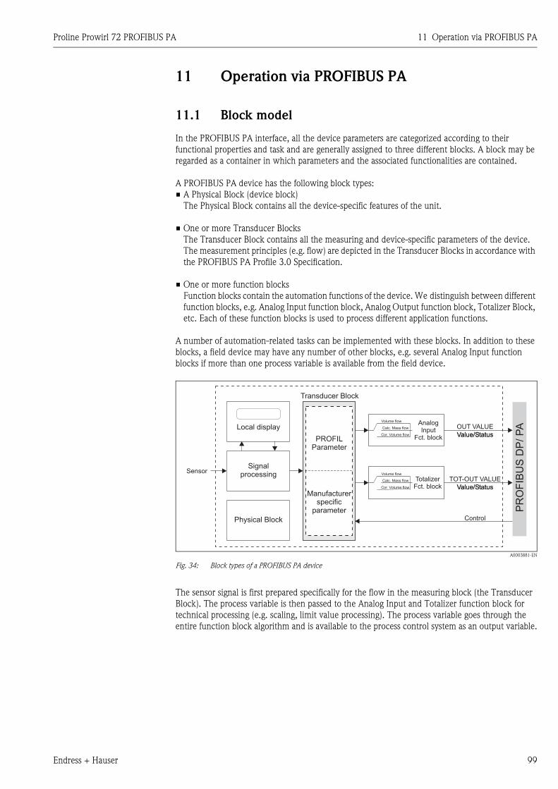
Proline Prowirl 72 PROFIBUS PA 11 Operation via PROFIBUS PA
Endress + Hauser 99
11 Operation via PROFIBUS PA
11.1 Block model
In the PROFIBUS PA interface, all the device parameters are categorized according to their
functional properties and task and are generally assigned to three different blocks. A block may be
regarded as a container in which parameters and the associated functionalities are contained.
A PROFIBUS PA device has the following block types:
• A Physical Block (device block)
The Physical Block contains all the device-specific features of the unit.
• One or more Transducer Blocks
The Transducer Block contains all the measuring and device-specific parameters of the device.
The measurement principles (e.g. flow) are depicted in the Transducer Blocks in accordance with
the PROFIBUS PA Profile 3.0 Specification.
• One or more function blocks
Function blocks contain the automation functions of the device. We distinguish between different
function blocks, e.g. Analog Input function block, Analog Output function block, Totalizer Block,
etc. Each of these function blocks is used to process different application functions.
A number of automation-related tasks can be implemented with these blocks. In addition to these
blocks, a field device may have any number of other blocks, e.g. several Analog Input function
blocks if more than one process variable is available from the field device.
A0003881-EN
Fig. 34: Block types of a PROFIBUS PA device
The sensor signal is first prepared specifically for the flow in the measuring block (the Transducer
Block). The process variable is then passed to the Analog Input and Totalizer function block for
technical processing (e.g. scaling, limit value processing). The process variable goes through the
entire function block algorithm and is available to the process control system as an output variable.
SensorSignal
processing
Physical Block
PROFILParameter
Manufacturerspecific
parameter
OUT VALUE
Value/Status
PR
OF
IBU
SD
P/
PA
TotalizerFct. block
TOT-OUT VALUE
Value/Status
Transducer Block
Value/Status
Value/StatusCor. Volume flow
Cor. Volume flow
Volume flow
Volume flow
Calc. Mass flow
Calc. Mass flow
Control
AnalogInput
Fct. block
Local display
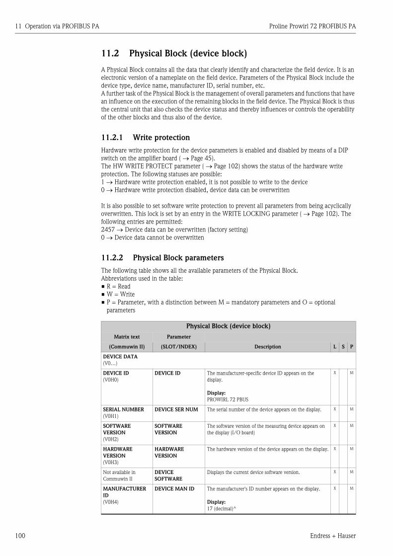
11 Operation via PROFIBUS PA Proline Prowirl 72 PROFIBUS PA
100 Endress + Hauser
11.2 Physical Block (device block)
A Physical Block contains all the data that clearly identify and characterize the field device. It is an
electronic version of a nameplate on the field device. Parameters of the Physical Block include the
device type, device name, manufacturer ID, serial number, etc.
A further task of the Physical Block is the management of overall parameters and functions that have
an influence on the execution of the remaining blocks in the field device. The Physical Block is thus
the central unit that also checks the device status and thereby influences or controls the operability
of the other blocks and thus also of the device.
11.2.1 Write protection
Hardware write protection for the device parameters is enabled and disabled by means of a DIP
switch on the amplifier board ( → Page 45).
The HW WRITE PROTECT parameter ( → Page 102) shows the status of the hardware write
protection. The following statuses are possible:
1 → Hardware write protection enabled, it is not possible to write to the device
0 → Hardware write protection disabled, device data can be overwritten
It is also possible to set software write protection to prevent all parameters from being acyclically
overwritten. This lock is set by an entry in the WRITE LOCKING parameter ( → Page 102). The
following entries are permitted:
2457 → Device data can be overwritten (factory setting)
0 → Device data cannot be overwritten
11.2.2 Physical Block parameters
The following table shows all the available parameters of the Physical Block.
Abbreviations used in the table:
• R = Read
• W = Write
• P = Parameter, with a distinction between M = mandatory parameters and O = optional
parameters
Physical Block (device block)
Matrix text Parameter
(Commuwin II) (SLOT/INDEX) Description L S P
DEVICE DATA
(V0…)
DEVICE ID
(V0H0)
DEVICE ID The manufacturer-specific device ID appears on the
display.
Display:
PROWIRL 72 PBUS
X M
SERIAL NUMBER
(V0H1)
DEVICE SER NUM The serial number of the device appears on the display. X M
SOFTWARE
VERSION
(V0H2)
SOFTWARE
VERSION
The software version of the measuring device appears on
the display (I/O board)
X M
HARDWARE
VERSION
(V0H3)
HARDWARE
VERSION
The hardware version of the device appears on the display. X M
Not available in
Commuwin II
DEVICE
SOFTWARE
Displays the current device software version. X M
MANUFACTURER
ID
(V0H4)
DEVICE MAN ID The manufacturer's ID number appears on the display.
Display:
17 (decimal)^
X M
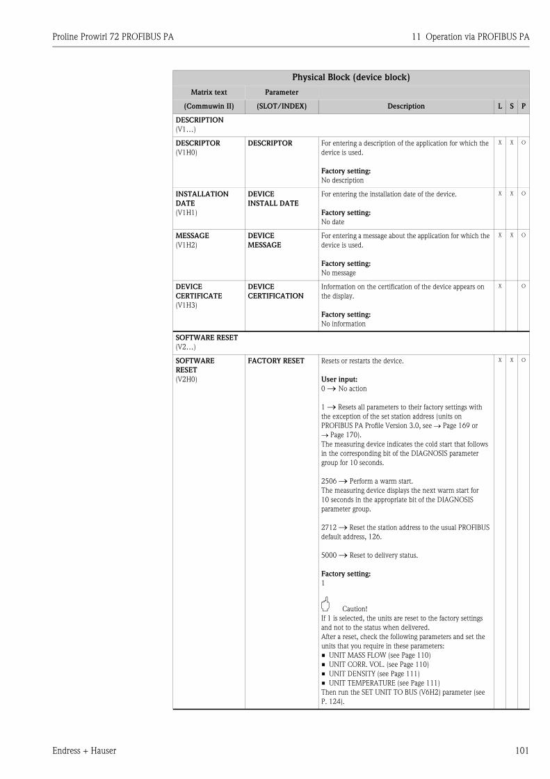
Proline Prowirl 72 PROFIBUS PA 11 Operation via PROFIBUS PA
Endress + Hauser 101
DESCRIPTION
(V1…)
DESCRIPTOR
(V1H0)
DESCRIPTOR For entering a description of the application for which the
device is used.
Factory setting:
No description
X X O
INSTALLATION
DATE
(V1H1)
DEVICE
INSTALL DATE
For entering the installation date of the device.
Factory setting:
No date
X X O
MESSAGE
(V1H2)
DEVICE
MESSAGE
For entering a message about the application for which the
device is used.
Factory setting:
No message
X X O
DEVICE
CERTIFICATE
(V1H3)
DEVICE
CERTIFICATION
Information on the certification of the device appears on
the display.
Factory setting:
No information
X O
SOFTWARE RESET
(V2…)
SOFTWARE
RESET
(V2H0)
FACTORY RESET Resets or restarts the device.
User input:
0 → No action
1 → Resets all parameters to their factory settings with
the exception of the set station address (units on
PROFIBUS PA Profile Version 3.0, see → Page 169 or → Page 170).
The measuring device indicates the cold start that follows
in the corresponding bit of the DIAGNOSIS parameter
group for 10 seconds.
2506 → Perform a warm start.
The measuring device displays the next warm start for
10 seconds in the appropriate bit of the DIAGNOSIS
parameter group.
2712 → Reset the station address to the usual PROFIBUS
default address, 126.
5000 → Reset to delivery status.
Factory setting:
1
" Caution!
If 1 is selected, the units are reset to the factory settings
and not to the status when delivered.
After a reset, check the following parameters and set the
units that you require in these parameters:
• UNIT MASS FLOW (see Page 110)
• UNIT CORR. VOL. (see Page 110)
• UNIT DENSITY (see Page 111)
• UNIT TEMPERATURE (see Page 111)
Then run the SET UNIT TO BUS (V6H2) parameter (see
P. 124).
X X O
Physical Block (device block)
Matrix text Parameter
(Commuwin II) (SLOT/INDEX) Description L S P
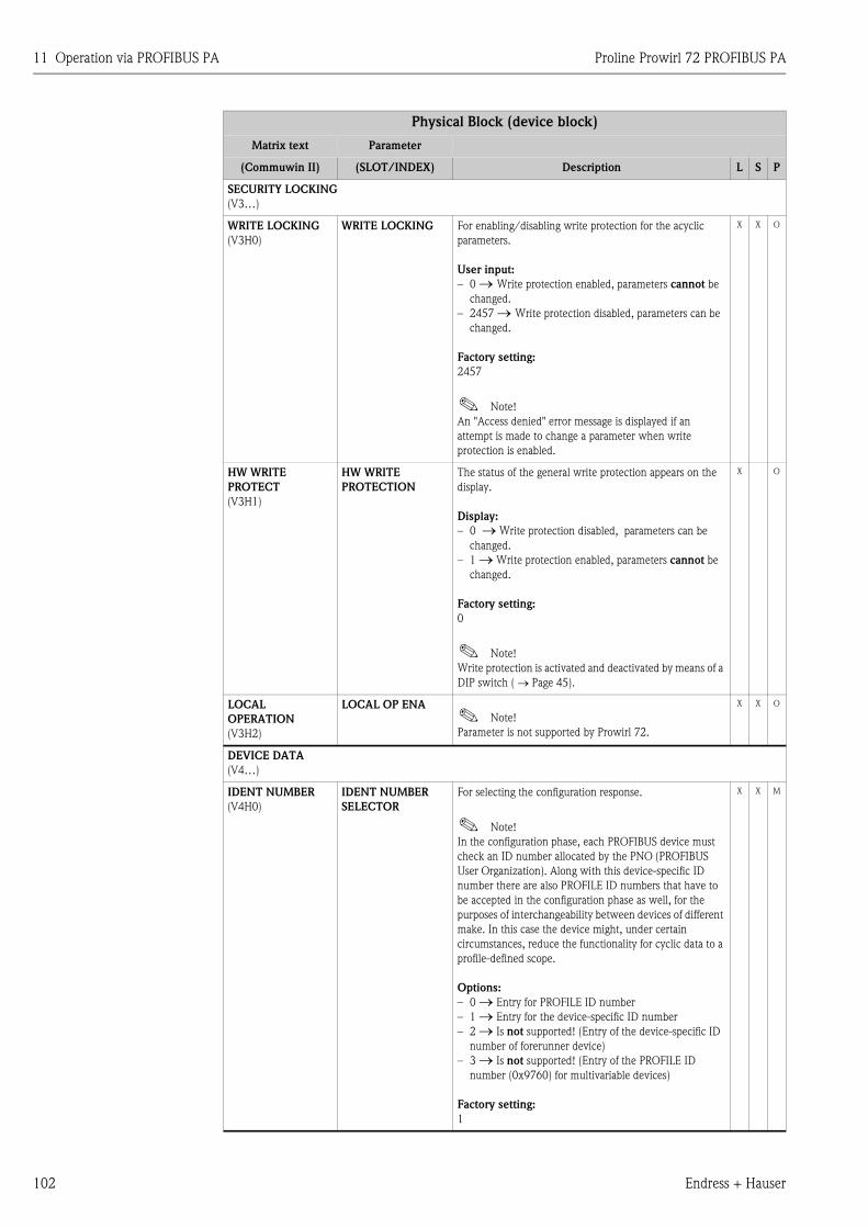
11 Operation via PROFIBUS PA Proline Prowirl 72 PROFIBUS PA
102 Endress + Hauser
SECURITY LOCKING
(V3…)
WRITE LOCKING
(V3H0)
WRITE LOCKING For enabling/disabling write protection for the acyclic
parameters.
User input:
– 0 → Write protection enabled, parameters cannot be
changed.
– 2457 → Write protection disabled, parameters can be
changed.
Factory setting:
2457
! Note!
An "Access denied" error message is displayed if an
attempt is made to change a parameter when write
protection is enabled.
X X O
HW WRITE
PROTECT
(V3H1)
HW WRITE
PROTECTION
The status of the general write protection appears on the
display.
Display:
– 0 → Write protection disabled, parameters can be
changed.
– 1 → Write protection enabled, parameters cannot be
changed.
Factory setting:
0
! Note!
Write protection is activated and deactivated by means of a
DIP switch ( → Page 45).
X O
LOCAL
OPERATION
(V3H2)
LOCAL OP ENA! Note!
Parameter is not supported by Prowirl 72.
X X O
DEVICE DATA
(V4…)
IDENT NUMBER
(V4H0)
IDENT NUMBER
SELECTOR
For selecting the configuration response.
! Note!
In the configuration phase, each PROFIBUS device must
check an ID number allocated by the PNO (PROFIBUS
User Organization). Along with this device-specific ID
number there are also PROFILE ID numbers that have to
be accepted in the configuration phase as well, for the
purposes of interchangeability between devices of different
make. In this case the device might, under certain
circumstances, reduce the functionality for cyclic data to a
profile-defined scope.
Options:
– 0 → Entry for PROFILE ID number
– 1 → Entry for the device-specific ID number
– 2 → Is not supported! (Entry of the device-specific ID
number of forerunner device)
– 3 → Is not supported! (Entry of the PROFILE ID
number (0x9760) for multivariable devices)
Factory setting:
1
X X M
Physical Block (device block)
Matrix text Parameter
(Commuwin II) (SLOT/INDEX) Description L S P
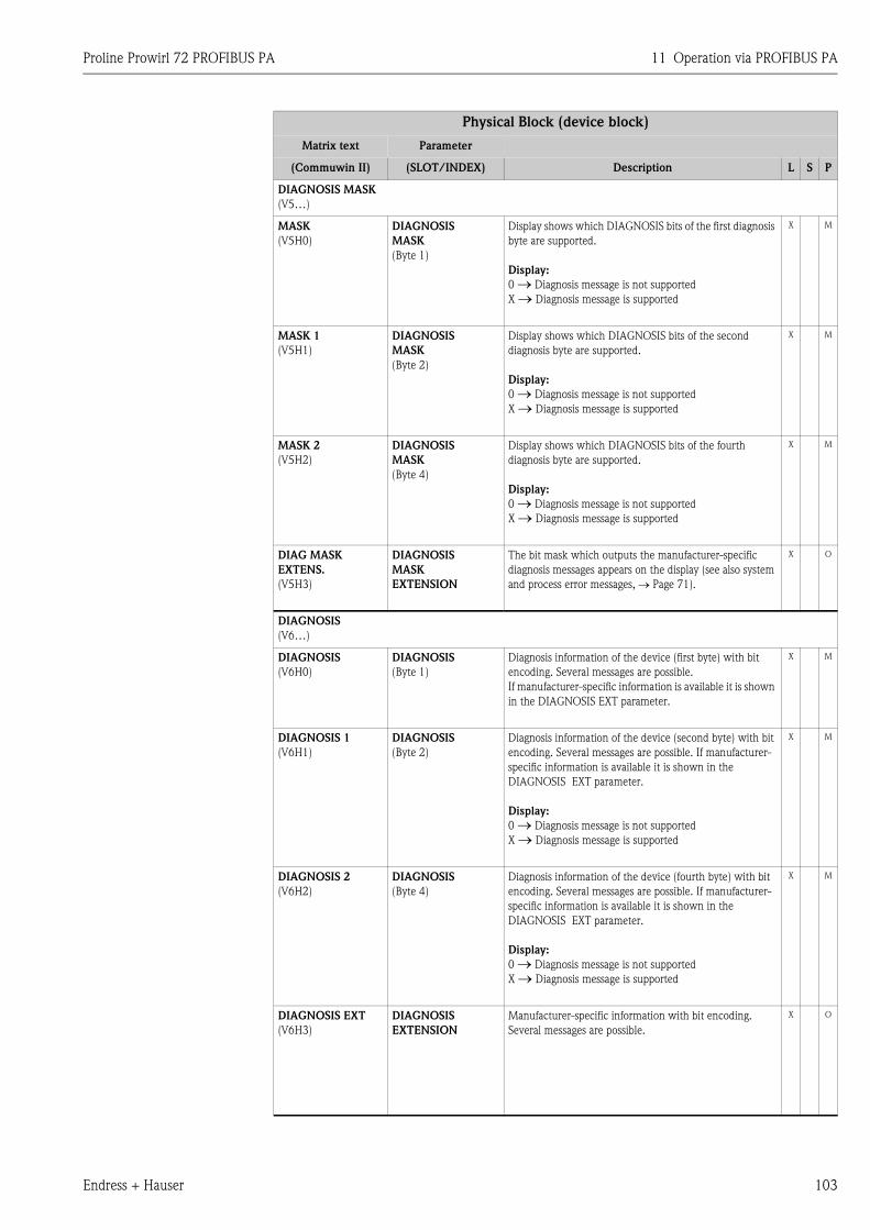
Proline Prowirl 72 PROFIBUS PA 11 Operation via PROFIBUS PA
Endress + Hauser 103
DIAGNOSIS MASK
(V5…)
MASK
(V5H0)
DIAGNOSIS
MASK
(Byte 1)
Display shows which DIAGNOSIS bits of the first diagnosis
byte are supported.
Display:
0 → Diagnosis message is not supported
X → Diagnosis message is supported
X M
MASK 1
(V5H1)
DIAGNOSIS
MASK
(Byte 2)
Display shows which DIAGNOSIS bits of the second
diagnosis byte are supported.
Display:
0 → Diagnosis message is not supported
X → Diagnosis message is supported
X M
MASK 2
(V5H2)
DIAGNOSIS
MASK
(Byte 4)
Display shows which DIAGNOSIS bits of the fourth
diagnosis byte are supported.
Display:
0 → Diagnosis message is not supported
X → Diagnosis message is supported
X M
DIAG MASK
EXTENS.
(V5H3)
DIAGNOSIS
MASK
EXTENSION
The bit mask which outputs the manufacturer-specific
diagnosis messages appears on the display (see also system
and process error messages, → Page 71).
X O
DIAGNOSIS
(V6…)
DIAGNOSIS
(V6H0)
DIAGNOSIS
(Byte 1)
Diagnosis information of the device (first byte) with bit
encoding. Several messages are possible.
If manufacturer-specific information is available it is shown
in the DIAGNOSIS EXT parameter.
X M
DIAGNOSIS 1
(V6H1)
DIAGNOSIS
(Byte 2)
Diagnosis information of the device (second byte) with bit
encoding. Several messages are possible. If manufacturer-
specific information is available it is shown in the
DIAGNOSIS EXT parameter.
Display:
0 → Diagnosis message is not supported
X → Diagnosis message is supported
X M
DIAGNOSIS 2
(V6H2)
DIAGNOSIS
(Byte 4)
Diagnosis information of the device (fourth byte) with bit
encoding. Several messages are possible. If manufacturer-
specific information is available it is shown in the
DIAGNOSIS EXT parameter.
Display:
0 → Diagnosis message is not supported
X → Diagnosis message is supported
X M
DIAGNOSIS EXT
(V6H3)
DIAGNOSIS
EXTENSION
Manufacturer-specific information with bit encoding.
Several messages are possible.
X O
Physical Block (device block)
Matrix text Parameter
(Commuwin II) (SLOT/INDEX) Description L S P
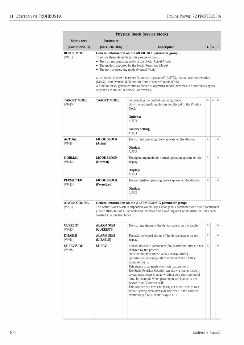
11 Operation via PROFIBUS PA Proline Prowirl 72 PROFIBUS PA
104 Endress + Hauser
BLOCK MODE
(V8…)
General information on the MODE BLK parameter group:
There are three elements in this parameter group:
• The current operating mode of the block (Actual Mode)
• The modes supported by the block (Permitted Mode)
• The normal operating mode (Normal Mode)
A distinction is drawn between "automatic operation" (AUTO), manual user intervention
(MAN), local override (LO) and the "out-of-service" mode (O/S).
A function block generally offers a choice of operating modes, whereas the other block types
only work in the AUTO mode, for example.
TARGET MODE
(V8H0)
TARGET MODE For selecting the desired operating mode.
Only the automatic mode can be selected in the Physical
Block.
Options:
AUTO
Factory setting:
AUTO
X X M
ACTUAL
(V8H1)
MODE BLOCK
(Actual)
The current operating mode appears on the display.
Display:
AUTO
X M
NORMAL
(V8H2)
MODE BLOCK
(Normal)
The operating mode for normal operation appears on the
display.
Display:
AUTO
X M
PERMITTED
(V8H3)
MODE BLOCK
(Permitted)
The permissible operating modes appear on the display.
Display:
AUTO
X M
ALARM CONFIG
(V9…)
General information on the ALARM CONFIG parameter group:
The Active Block Alarm is supported which flags a change in a parameter with static parameters
( Static attribute) for 10 seconds and indicates that a warning limit or an alarm limit has been
violated in a function block.
CURRENT
(V9H0)
ALARM SUM
(CURRENT)
The current alarms of the device appear on the display. X M
DISABLE
(V9H1)
ALARM SUM
(DISABLE)
The acknowledged alarms of the device appear on the
display.
X M
ST REVISION
(V9H5)
ST REV A block has static parameters (Static attribute) that are not
changed by the process.
Static parameters whose values change during
optimization or configuration increment the ST REV
parameter by 1.
This supports parameter-revision management.
The Static Revision Counter can show a higher value if
several parameters change within a very short period of
time, for example when parameters are loaded to the
device from Commuwin II.
This counter can never be reset, nor does it return to a
default setting even after a device reset. If the counter
overflows (16 bits), it starts again at 1.
X M
Physical Block (device block)
Matrix text Parameter
(Commuwin II) (SLOT/INDEX) Description L S P
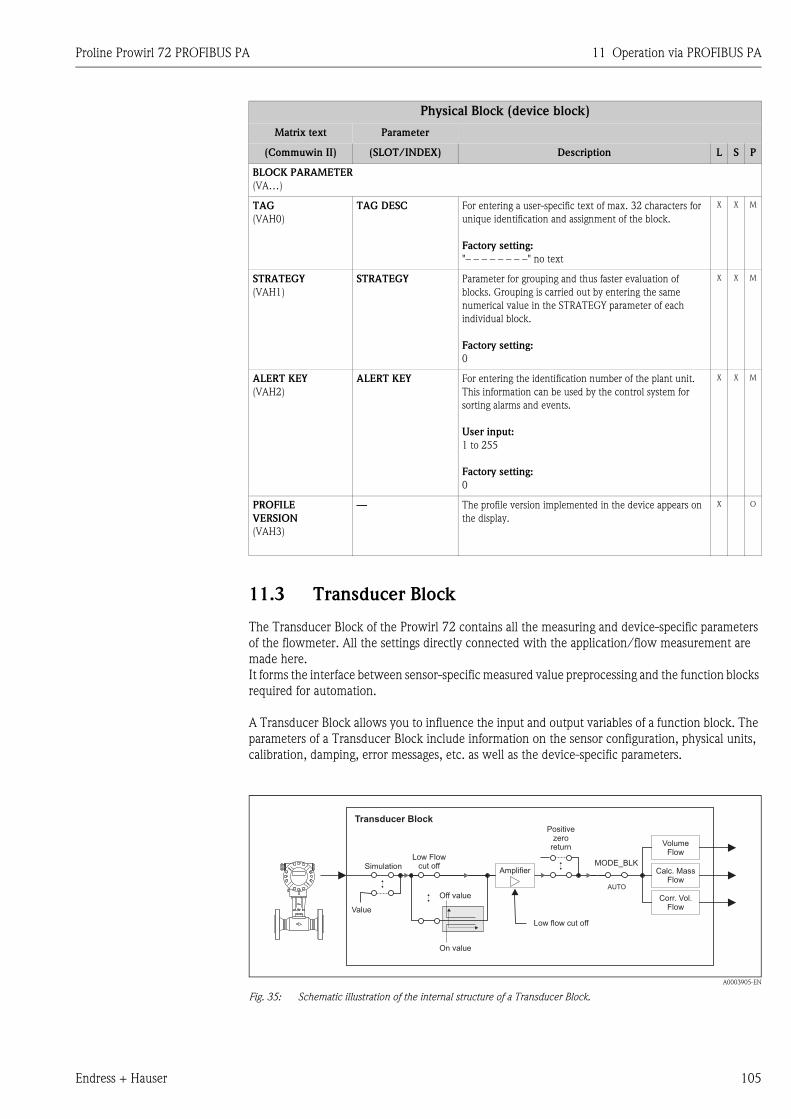
Proline Prowirl 72 PROFIBUS PA 11 Operation via PROFIBUS PA
Endress + Hauser 105
11.3 Transducer Block
The Transducer Block of the Prowirl 72 contains all the measuring and device-specific parameters
of the flowmeter. All the settings directly connected with the application/flow measurement are
made here.
It forms the interface between sensor-specific measured value preprocessing and the function blocks
required for automation.
A Transducer Block allows you to influence the input and output variables of a function block. The
parameters of a Transducer Block include information on the sensor configuration, physical units,
calibration, damping, error messages, etc. as well as the device-specific parameters.
A0003905-EN
Fig. 35: Schematic illustration of the internal structure of a Transducer Block.
BLOCK PARAMETER
(VA…)
TAG
(VAH0)
TAG DESC For entering a user-specific text of max. 32 characters for
unique identification and assignment of the block.
Factory setting:
"– – – – – – – –" no text
X X M
STRATEGY
(VAH1)
STRATEGY Parameter for grouping and thus faster evaluation of
blocks. Grouping is carried out by entering the same
numerical value in the STRATEGY parameter of each
individual block.
Factory setting:
0
X X M
ALERT KEY
(VAH2)
ALERT KEY For entering the identification number of the plant unit.
This information can be used by the control system for
sorting alarms and events.
User input:
1 to 255
Factory setting:
0
X X M
PROFILE
VERSION
(VAH3)
— The profile version implemented in the device appears on
the display.
X O
Physical Block (device block)
Matrix text Parameter
(Commuwin II) (SLOT/INDEX) Description L S P
Transducer Block
Low flow cut off
AUTO
Off value
On value
Simulation
Positivezero
return
MODE_BLKLow Flow
cut off
Value
Amplifier
VolumeFlow
Calc. MassFlow
Corr. Vol.Flow
11 Operation via PROFIBUS PA Proline Prowirl 72 PROFIBUS PA
106 Endress + Hauser
11.3.1 Signal processing
The Transducer Block receives a signal variable from the sensor (volume flow) as the input variable.
Other process variables, such as calculated mass flow and corrected volume flow, are derived from
these signal variables. The input signals are prepared for measuring via the amplifier.
The VALUE SIM. MEAS parameter (see Page 131) allows you to specify a simulation value for the
Transducer Block in order to test assigned parameters in the device and downstream function
blocks.
A low flow cut off allows you to hide measurement inaccuracies in the low flow range.
You can define a limit value via the ON VAL LF CUTOFF parameter (see Page 120). If the measured
flow value undershoots this limit value, the output value of 0 is output.
You also have the option of setting the measured value to "zero flow" by means of the POSITIVE
ZERO RETURN parameter (see Page 122). This is necessary when the piping system is being
cleaned, for example.
The process variables of the Transducer Block are output via the following parameters:
• VOLUME FLOW (volume flow) → Page 107
• CALC. MASS FL. (calculated mass flow) → Page 107
• CORRECTED VOLUME FLOW (corrected volume flow) → Page 108
The most important functions and parameters of the Transducer Block are listed below. An
overview of all the parameters available is provided from Page 107 onwards.
11.3.2 Block output variables
The Transducer Block has three process variables: volume flow, calculated mass flow and corrected
volume flow. All three process variables are made available to the downstream function blocks for
further processing.
11.3.3 Alarm detection and processing
The Transducer Block does not generate any process alarms. The status of the process variable of
the Transducer Block is evaluated in the downstream Analog Input function block. If the Analog
Input function block does not receive an input value that can be evaluated from the Transducer
Block, then a process alarm is generated.
This process alarm is displayed via the OUT STATUS, OUT SUB STATUS and OUT LIMIT
parameters of the Analog Input function block (see Page 140).
More detailed information on the current device status is provided in the manufacturer-specific
ACTUAL.SYS.COND parameter (see Page 130).
This parameter also displays a device error that produced an input value that could not be evaluated
and thus triggered the process alarm in the Analog Input function block.
More information on eliminating errors can be found on Page 69.
11.3.4 Accessing the manufacturer-specific parameters
To access the manufacturer-specific parameters, the following requirements must be met:
1. Hardware write protection must be disabled (see Page 100).
2. The correct code must be entered in the DEFINE PRIVATE CODE parameter (see Page 113).
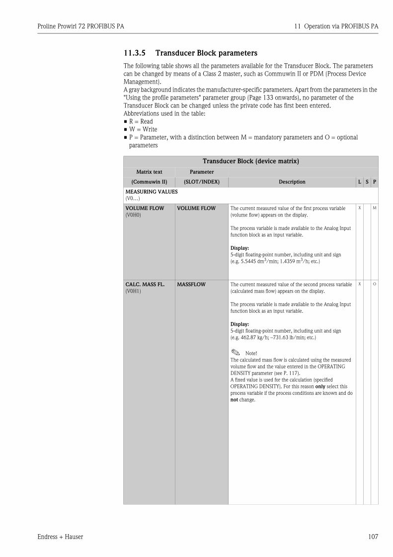
Proline Prowirl 72 PROFIBUS PA 11 Operation via PROFIBUS PA
Endress + Hauser 107
11.3.5 Transducer Block parameters
The following table shows all the parameters available for the Transducer Block. The parameters
can be changed by means of a Class 2 master, such as Commuwin II or PDM (Process Device
Management).
A gray background indicates the manufacturer-specific parameters. Apart from the parameters in the
"Using the profile parameters" parameter group (Page 133 onwards), no parameter of the
Transducer Block can be changed unless the private code has first been entered.
Abbreviations used in the table:
• R = Read
• W = Write
• P = Parameter, with a distinction between M = mandatory parameters and O = optional
parameters
Transducer Block (device matrix)
Matrix text Parameter
(Commuwin II) (SLOT/INDEX) Description L S P
MEASURING VALUES
(V0…)
VOLUME FLOW
(V0H0)
VOLUME FLOW The current measured value of the first process variable
(volume flow) appears on the display.
The process variable is made available to the Analog Input
function block as an input variable.
Display:
5-digit floating-point number, including unit and sign
(e.g. 5.5445 dm3/min; 1.4359 m3/h; etc.)
X M
CALC. MASS FL.
(V0H1)
MASSFLOW The current measured value of the second process variable
(calculated mass flow) appears on the display.
The process variable is made available to the Analog Input
function block as an input variable.
Display:
5-digit floating-point number, including unit and sign
(e.g. 462.87 kg/h; –731.63 lb/min; etc.)
! Note!
The calculated mass flow is calculated using the measured
volume flow and the value entered in the OPERATING
DENSITY parameter (see P. 117).
A fixed value is used for the calculation (specified
OPERATING DENSITY). For this reason only select this
process variable if the process conditions are known and do
not change.
X O
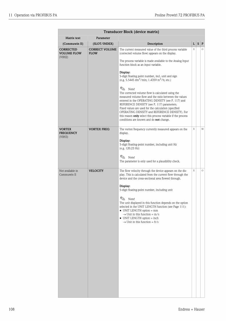
11 Operation via PROFIBUS PA Proline Prowirl 72 PROFIBUS PA
108 Endress + Hauser
CORRECTED
VOLUME FLOW
(V0H2)
CORRECT VOLUME
FLOW
The current measured value of the third process variable
(corrected volume flow) appears on the display.
The process variable is made available to the Analog Input
function block as an input variable.
Display:
5-digit floating point number, incl. unit and sign
(e.g. 5.5445 dm3/min; 1.4359 m3/h; etc.)
! Note!
The corrected volume flow is calculated using the
measured volume flow and the ratio between the values
entered in the OPERATING DENSITY (see P. 117) and
REFERENCE DENSITY (see P. 117) parameters.
Fixed values are used for the calculation (specified
OPERATING DENSITY and REFERENCE DENSITY). For
this reason only select this process variable if the process
conditions are known and do not change.
X O
VORTEX
FREQUENCY
(V0H3)
VORTEX FREQ The vortex frequency currently measured appears on the
display.
Display:
5-digit floating-point number, including unit Hz
(e.g. 120.23 Hz)
! Note!
The parameter is only used for a plausibility check.
X M
Not available in
Commuwin II
VELOCITY The flow velocity through the device appears on the dis-
play. This is calculated from the current flow through the
device and the cross-sectional area flowed through.
Display:
5-digit floating-point number, including unit
! Note!
The unit displayed in this function depends on the option
selected in the UNIT LENGTH function (see Page 111):
• UNIT LENGTH option = mm
→ Unit in this function = m/s
• UNIT LENGTH option = inch
→ Unit in this function = ft/s
X O
Transducer Block (device matrix)
Matrix text Parameter
(Commuwin II) (SLOT/INDEX) Description L S P
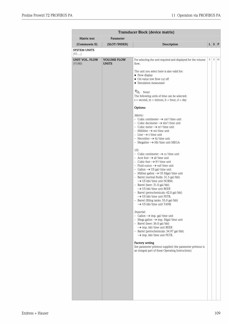
Proline Prowirl 72 PROFIBUS PA 11 Operation via PROFIBUS PA
Endress + Hauser 109
SYSTEM UNITS
(V1…)
UNIT VOL. FLOW
(V1H0)
VOLUME FLOW
UNITS
For selecting the unit required and displayed for the volume
flow.
The unit you select here is also valid for:
• Flow display
• On-value low flow cut off
• Simulation measurand
! Note!
The following units of time can be selected:
s = second, m = minute, h = hour, d = day
Options:
Metric:
– Cubic centimeter → cm³/time unit
– Cubic decimeter → dm³/time unit
– Cubic meter → m³/time unit
– Milliliter → ml/time unit
– Liter → l/time unit
– Hectoliter → hl/time unit
– Megaliter → Ml/time unit MEGA
US:
– Cubic centimeter → cc/time unit
– Acre foot → af/time unit
– Cubic foot → ft³/time unit
– Fluid ounce → ozf/time unit
– Gallon → US gal/time unit
– Million gallon → US Mgal/time unit
– Barrel (normal fluids: 31.5 gal/bbl)
→ US bbl/time unit NORM.
– Barrel (beer: 31.0 gal/bbl)
→ US bbl/time unit BEER
– Barrel (petrochemicals: 42.0 gal/bbl)
→ US bbl/time unit PETR.
– Barrel (filling tanks: 55.0 gal/bbl)
→ US bbl/time unit TANK
Imperial:
– Gallon → imp. gal/time unit
– Mega gallon → imp. Mgal/time unit
– Barrel (beer: 36.0 gal/bbl)
→ imp. bbl/time unit BEER
– Barrel (petrochemicals: 34.97 gal/bbl)
→ imp. bbl/time unit PETR.
Factory setting
See parameter printout supplied (the parameter printout is
an integral part of these Operating Instructions)
X X M
Transducer Block (device matrix)
Matrix text Parameter
(Commuwin II) (SLOT/INDEX) Description L S P
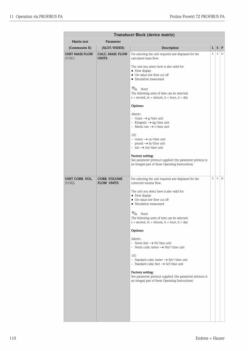
11 Operation via PROFIBUS PA Proline Prowirl 72 PROFIBUS PA
110 Endress + Hauser
UNIT MASS FLOW
(V1H1)
CALC. MASS FLOW
UNITS
For selecting the unit required and displayed for the
calculated mass flow.
The unit you select here is also valid for:
• Flow display
• On-value low flow cut off
• Simulation measurand
! Note!
The following units of time can be selected:
s = second, m = minute, h = hour, d = day
Options:
Metric:
– Gram → g/time unit
– Kilogram → kg/time unit
– Metric ton → t/time unit
US:
– ounce → oz/time unit
– pound → lb/time unit
– ton → ton/time unit
Factory setting:
See parameter printout supplied (the parameter printout is
an integral part of these Operating Instructions)
X X M
UNIT CORR. VOL.
(V1H2)
CORR. VOLUME
FLOW UNITS
For selecting the unit required and displayed for the
corrected volume flow.
The unit you select here is also valid for:
• Flow display
• On-value low flow cut off
• Simulation measurand
! Note!
The following units of time can be selected:
s = second, m = minute, h = hour, d = day
Options:
Metric:
– Norm liter → Nl/time unit
– Norm cubic meter → Nm³/time unit
US:
– Standard cubic meter → Sm³/time unit
– Standard cubic feet → Scf/time unit
Factory setting:
See parameter printout supplied (the parameter printout is
an integral part of these Operating Instructions)
X X M
Transducer Block (device matrix)
Matrix text Parameter
(Commuwin II) (SLOT/INDEX) Description L S P
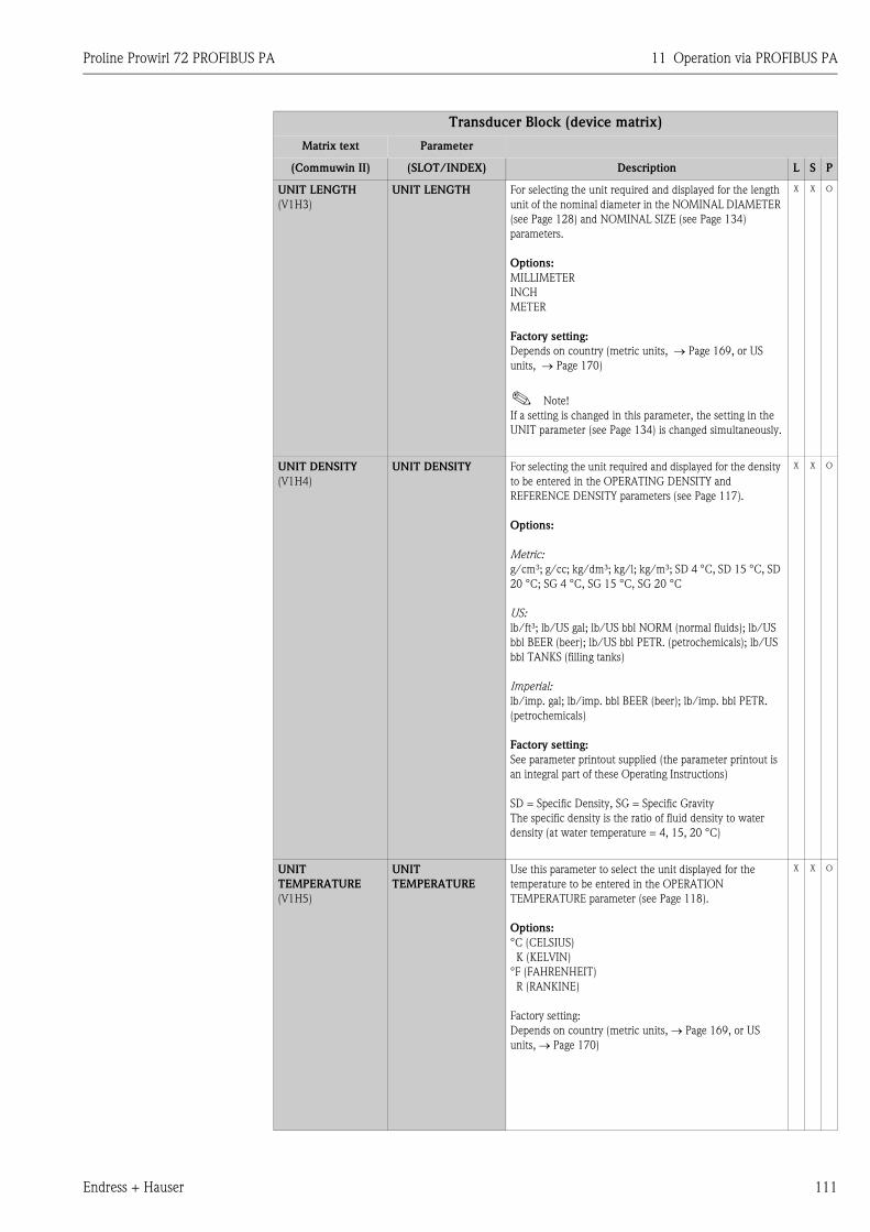
Proline Prowirl 72 PROFIBUS PA 11 Operation via PROFIBUS PA
Endress + Hauser 111
UNIT LENGTH
(V1H3)
UNIT LENGTH For selecting the unit required and displayed for the length
unit of the nominal diameter in the NOMINAL DIAMETER
(see Page 128) and NOMINAL SIZE (see Page 134)
parameters.
Options:
MILLIMETER
INCH
METER
Factory setting:
Depends on country (metric units, → Page 169, or US
units, → Page 170)
! Note!
If a setting is changed in this parameter, the setting in the
UNIT parameter (see Page 134) is changed simultaneously.
X X O
UNIT DENSITY
(V1H4)
UNIT DENSITY For selecting the unit required and displayed for the density
to be entered in the OPERATING DENSITY and
REFERENCE DENSITY parameters (see Page 117).
Options:
Metric:
g/cm³; g/cc; kg/dm³; kg/l; kg/m³; SD 4 °C, SD 15 °C, SD
20 °C; SG 4 °C, SG 15 °C, SG 20 °C
US:
lb/ft³; lb/US gal; lb/US bbl NORM (normal fluids); lb/US
bbl BEER (beer); lb/US bbl PETR. (petrochemicals); lb/US
bbl TANKS (filling tanks)
Imperial:
lb/imp. gal; lb/imp. bbl BEER (beer); lb/imp. bbl PETR.
(petrochemicals)
Factory setting:
See parameter printout supplied (the parameter printout is
an integral part of these Operating Instructions)
SD = Specific Density, SG = Specific Gravity
The specific density is the ratio of fluid density to water
density (at water temperature = 4, 15, 20 °C)
X X O
UNIT
TEMPERATURE
(V1H5)
UNIT
TEMPERATURE
Use this parameter to select the unit displayed for the
temperature to be entered in the OPERATION
TEMPERATURE parameter (see Page 118).
Options:
°C (CELSIUS)
K (KELVIN)
°F (FAHRENHEIT)
R (RANKINE)
Factory setting:
Depends on country (metric units, → Page 169, or US
units, → Page 170)
X X O
Transducer Block (device matrix)
Matrix text Parameter
(Commuwin II) (SLOT/INDEX) Description L S P
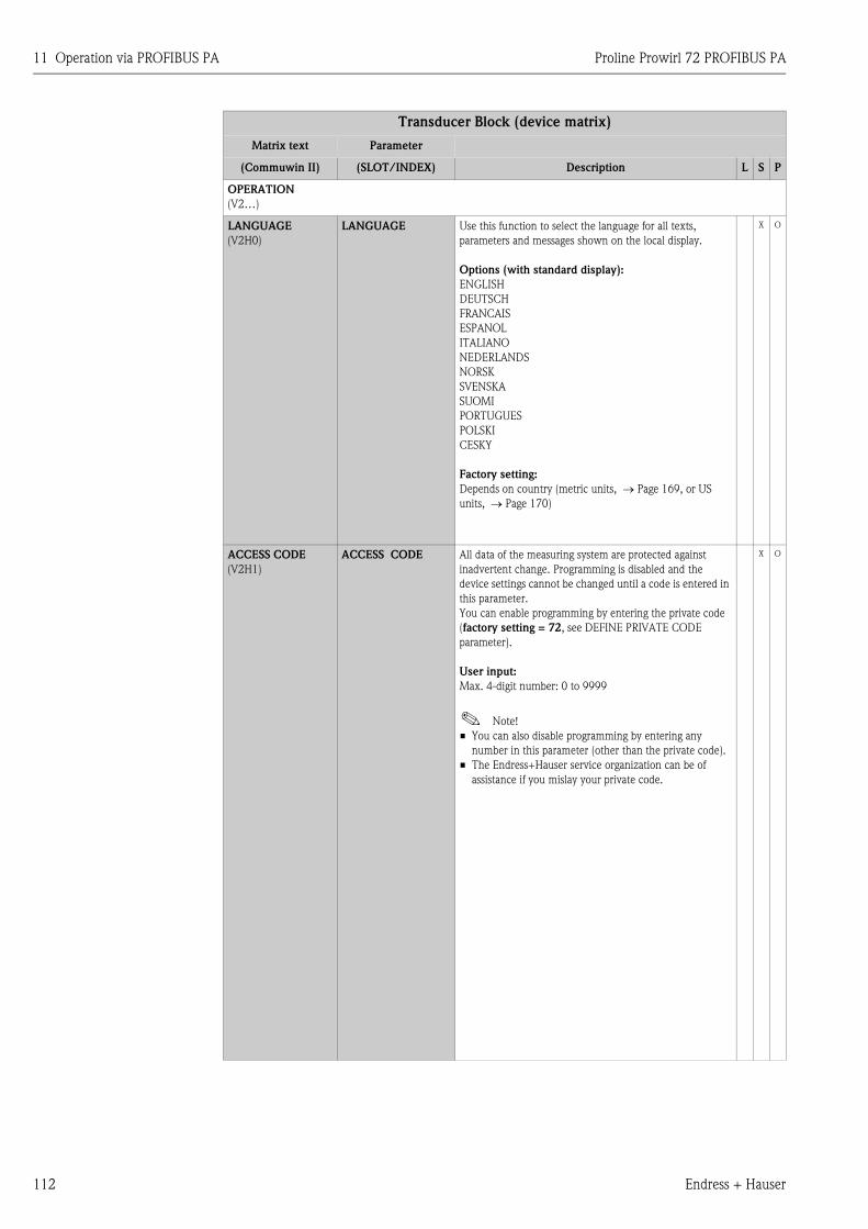
11 Operation via PROFIBUS PA Proline Prowirl 72 PROFIBUS PA
112 Endress + Hauser
OPERATION
(V2…)
LANGUAGE
(V2H0)
LANGUAGE Use this function to select the language for all texts,
parameters and messages shown on the local display.
Options (with standard display):
ENGLISH
DEUTSCH
FRANCAIS
ESPANOL
ITALIANO
NEDERLANDS
NORSK
SVENSKA
SUOMI
PORTUGUES
POLSKI
CESKY
Factory setting:
Depends on country (metric units, → Page 169, or US
units, → Page 170)
X O
ACCESS CODE
(V2H1)
ACCESS CODE All data of the measuring system are protected against
inadvertent change. Programming is disabled and the
device settings cannot be changed until a code is entered in
this parameter.
You can enable programming by entering the private code
(factory setting = 72, see DEFINE PRIVATE CODE
parameter).
User input:
Max. 4-digit number: 0 to 9999
! Note!
• You can also disable programming by entering any
number in this parameter (other than the private code).
• The Endress+Hauser service organization can be of
assistance if you mislay your private code.
X O
Transducer Block (device matrix)
Matrix text Parameter
(Commuwin II) (SLOT/INDEX) Description L S P
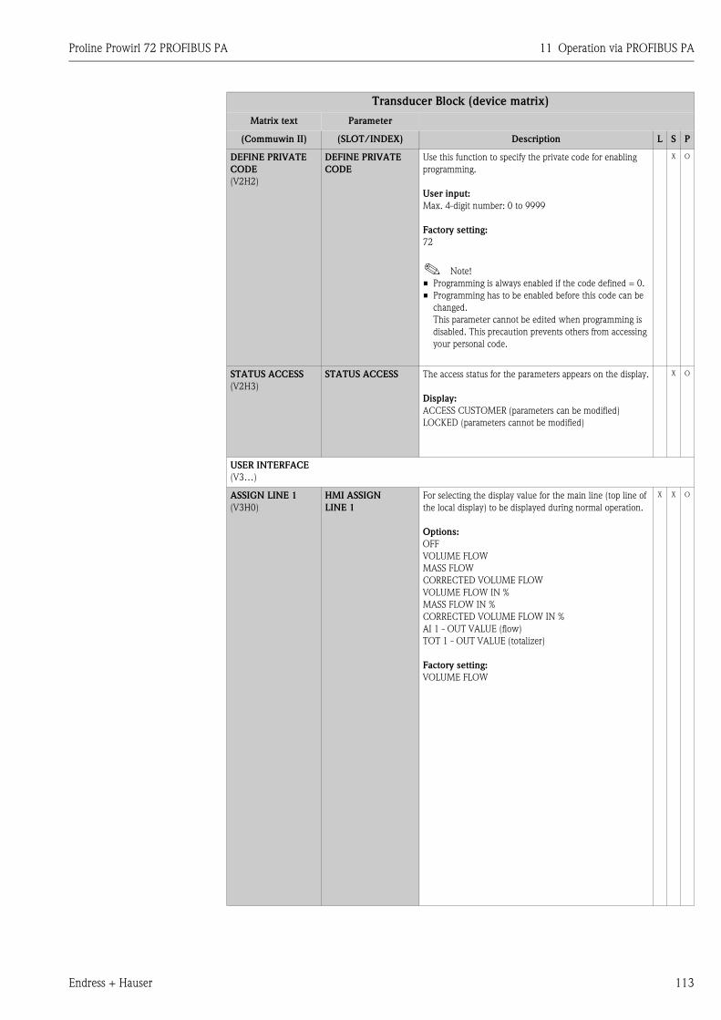
Proline Prowirl 72 PROFIBUS PA 11 Operation via PROFIBUS PA
Endress + Hauser 113
DEFINE PRIVATE
CODE
(V2H2)
DEFINE PRIVATE
CODE
Use this function to specify the private code for enabling
programming.
User input:
Max. 4-digit number: 0 to 9999
Factory setting:
72
! Note!
• Programming is always enabled if the code defined = 0.
• Programming has to be enabled before this code can be
changed.
This parameter cannot be edited when programming is
disabled. This precaution prevents others from accessing
your personal code.
X O
STATUS ACCESS
(V2H3)
STATUS ACCESS The access status for the parameters appears on the display.
Display:
ACCESS CUSTOMER (parameters can be modified)
LOCKED (parameters cannot be modified)
X O
USER INTERFACE
(V3…)
ASSIGN LINE 1
(V3H0)
HMI ASSIGN
LINE 1
For selecting the display value for the main line (top line of
the local display) to be displayed during normal operation.
Options:
OFF
VOLUME FLOW
MASS FLOW
CORRECTED VOLUME FLOW
VOLUME FLOW IN %
MASS FLOW IN %
CORRECTED VOLUME FLOW IN %
AI 1 - OUT VALUE (flow)
TOT 1 - OUT VALUE (totalizer)
Factory setting:
VOLUME FLOW
X X O
Transducer Block (device matrix)
Matrix text Parameter
(Commuwin II) (SLOT/INDEX) Description L S P
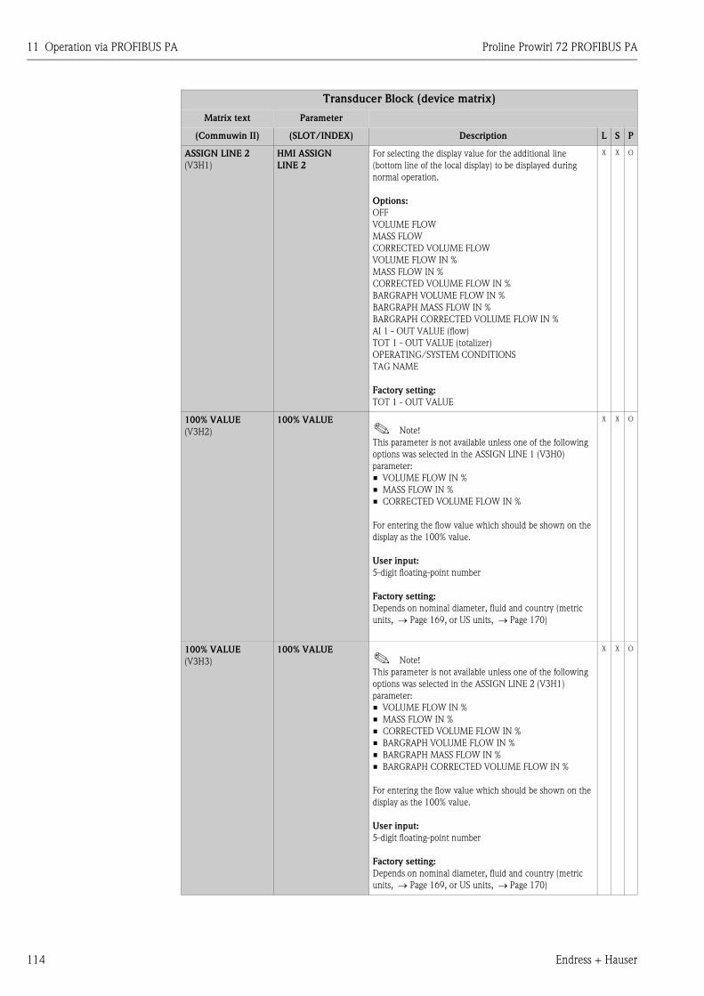
11 Operation via PROFIBUS PA Proline Prowirl 72 PROFIBUS PA
114 Endress + Hauser
ASSIGN LINE 2
(V3H1)
HMI ASSIGN
LINE 2
For selecting the display value for the additional line
(bottom line of the local display) to be displayed during
normal operation.
Options:
OFF
VOLUME FLOW
MASS FLOW
CORRECTED VOLUME FLOW
VOLUME FLOW IN %
MASS FLOW IN %
CORRECTED VOLUME FLOW IN %
BARGRAPH VOLUME FLOW IN %
BARGRAPH MASS FLOW IN %
BARGRAPH CORRECTED VOLUME FLOW IN %
AI 1 - OUT VALUE (flow)
TOT 1 - OUT VALUE (totalizer)
OPERATING/SYSTEM CONDITIONS
TAG NAME
Factory setting:
TOT 1 - OUT VALUE
X X O
100% VALUE
(V3H2)
100% VALUE! Note!
This parameter is not available unless one of the following
options was selected in the ASSIGN LINE 1 (V3H0)
parameter:
• VOLUME FLOW IN %
• MASS FLOW IN %
• CORRECTED VOLUME FLOW IN %
For entering the flow value which should be shown on the
display as the 100% value.
User input:
5-digit floating-point number
Factory setting:
Depends on nominal diameter, fluid and country (metric
units, → Page 169, or US units, → Page 170)
X X O
100% VALUE
(V3H3)
100% VALUE! Note!
This parameter is not available unless one of the following
options was selected in the ASSIGN LINE 2 (V3H1)
parameter:
• VOLUME FLOW IN %
• MASS FLOW IN %
• CORRECTED VOLUME FLOW IN %
• BARGRAPH VOLUME FLOW IN %
• BARGRAPH MASS FLOW IN %
• BARGRAPH CORRECTED VOLUME FLOW IN %
For entering the flow value which should be shown on the
display as the 100% value.
User input:
5-digit floating-point number
Factory setting:
Depends on nominal diameter, fluid and country (metric
units, → Page 169, or US units, → Page 170)
X X O
Transducer Block (device matrix)
Matrix text Parameter
(Commuwin II) (SLOT/INDEX) Description L S P
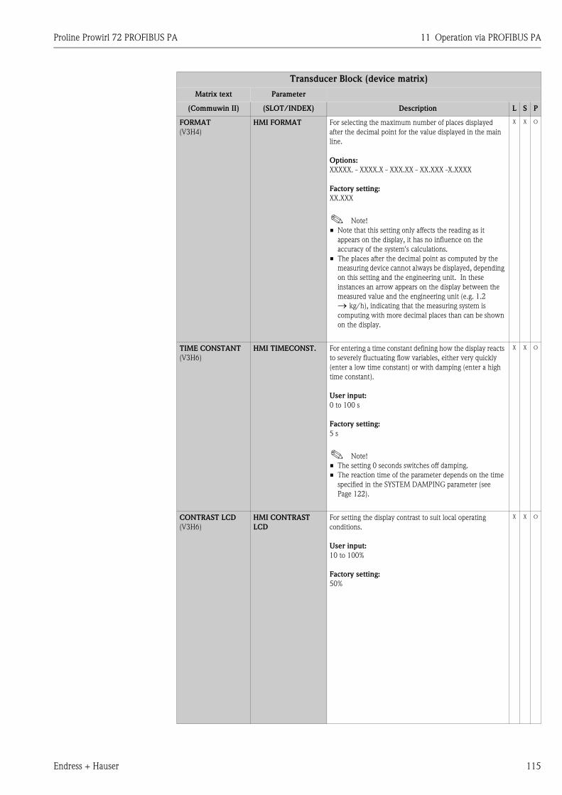
Proline Prowirl 72 PROFIBUS PA 11 Operation via PROFIBUS PA
Endress + Hauser 115
FORMAT
(V3H4)
HMI FORMAT For selecting the maximum number of places displayed
after the decimal point for the value displayed in the main
line.
Options:
XXXXX. - XXXX.X - XXX.XX - XX.XXX -X.XXXX
Factory setting:
XX.XXX
! Note!
• Note that this setting only affects the reading as it
appears on the display, it has no influence on the
accuracy of the system's calculations.
• The places after the decimal point as computed by the
measuring device cannot always be displayed, depending
on this setting and the engineering unit. In these
instances an arrow appears on the display between the
measured value and the engineering unit (e.g. 1.2 → kg/h), indicating that the measuring system is
computing with more decimal places than can be shown
on the display.
X X O
TIME CONSTANT
(V3H6)
HMI TIMECONST. For entering a time constant defining how the display reacts
to severely fluctuating flow variables, either very quickly
(enter a low time constant) or with damping (enter a high
time constant).
User input:
0 to 100 s
Factory setting:
5 s
! Note!
• The setting 0 seconds switches off damping.
• The reaction time of the parameter depends on the time
specified in the SYSTEM DAMPING parameter (see
Page 122).
X X O
CONTRAST LCD
(V3H6)
HMI CONTRAST
LCD
For setting the display contrast to suit local operating
conditions.
User input:
10 to 100%
Factory setting:
50%
X X O
Transducer Block (device matrix)
Matrix text Parameter
(Commuwin II) (SLOT/INDEX) Description L S P
11 Operation via PROFIBUS PA Proline Prowirl 72 PROFIBUS PA
116 Endress + Hauser
TEST DISPLAY
(V3H6)
HMI TEST DISP. Use this function to test the operability of the local display
and its pixels.
Options:
OFF
ON
Factory setting:
OFF
Test sequence:
1. Start the test by selecting ON.
2. All pixels of the main line and additional line are
darkened for minimum 0.75 seconds.
3. The main line and additional line show an "8" in each
field for minimum 0.75 seconds.
4. The main line and additional line show a "0" in each
field for minimum 0.75 seconds.
5. The main line and additional line show nothing (blank
display) for minimum 0.75 seconds.
6. When the test is completed, the local display returns to
its initial state and the displays the option OFF.
X X O
PROCESS PARAMETER
(V4…)
APPLICATION
(V4H0)
APPLICATION For selecting the state of aggregation of the fluid.
Options:
GAS/STEAM
LIQUID
Factory setting:
See parameter printout supplied (the parameter printout is
an integral part of these Operating Instructions)
! Note!
If the selection is changed in this function, you are asked
whether the totalizer should be reset to 0. We recommend
you confirm this message and perform a reset.
X X O
Transducer Block (device matrix)
Matrix text Parameter
(Commuwin II) (SLOT/INDEX) Description L S P
Proline Prowirl 72 PROFIBUS PA 11 Operation via PROFIBUS PA
Endress + Hauser 117
OPERATING
DENSITY
(V4H1)
FIX.OPN.DENSITY For entering a fixed value for the density at process
conditions. This value is used to calculate the calculated
mass flow and corrected volume flow.
User input:
5-digit floating-point number
Factory setting:
See parameter printout supplied (the parameter printout is
an integral part of these Operating Instructions)
! Note!
• The appropriate unit is taken from the UNIT DENSITY
parameter (see Page 111).
• If the selection is changed in this function, you are asked
whether the totalizer should be reset to 0. We
recommend you confirm this message and perform a
reset.
X X O
REFERENCE
DENSITY
(V4H2)
REF.DENSITY For entering a fixed value for the density at reference
conditions. This value is used to calculate the corrected
volume flow.
User input:
5-digit floating-point number
Factory setting:
See parameter printout supplied (the parameter printout is
an integral part of these Operating Instructions)
! Note!
• The appropriate unit is taken from the UNIT DENSITY
parameter (see Page 111).
• If the value in this parameter is changed, we recommend
you reset the totalizer.
X X O
Transducer Block (device matrix)
Matrix text Parameter
(Commuwin II) (SLOT/INDEX) Description L S P
11 Operation via PROFIBUS PA Proline Prowirl 72 PROFIBUS PA
118 Endress + Hauser
OPERATION
TEMPERATURE
(V4H3)
FIX.OPN.TEMP. For entering a fixed value for the process temperature.
! Note!
The sensor (measuring pipe and bluff body) expands
differently depending on the existing process temperature.
This has a proportional effect on the accuracy of the
measuring system since the device was calibrated at a fixed
calibration temperature of 20 °C (293 K).
However, this effect on the current measured value and the
internal totalizer can be compensated by entering an
average process temperature in this parameter.
User input:
5-digit floating-point number
Factory setting:
20°C / 293.16 K / 68 °F / 527.67 R
! Note!
The appropriate unit is taken from the UNIT
TEMPERATURE parameter ( → Page 111).
" Caution!
This setting does not change the permitted temperature
range of the measuring system.
Please pay particular attention to the temperature
application limits specified in the product specification (see
Page 88).
X X O
Transducer Block (device matrix)
Matrix text Parameter
(Commuwin II) (SLOT/INDEX) Description L S P
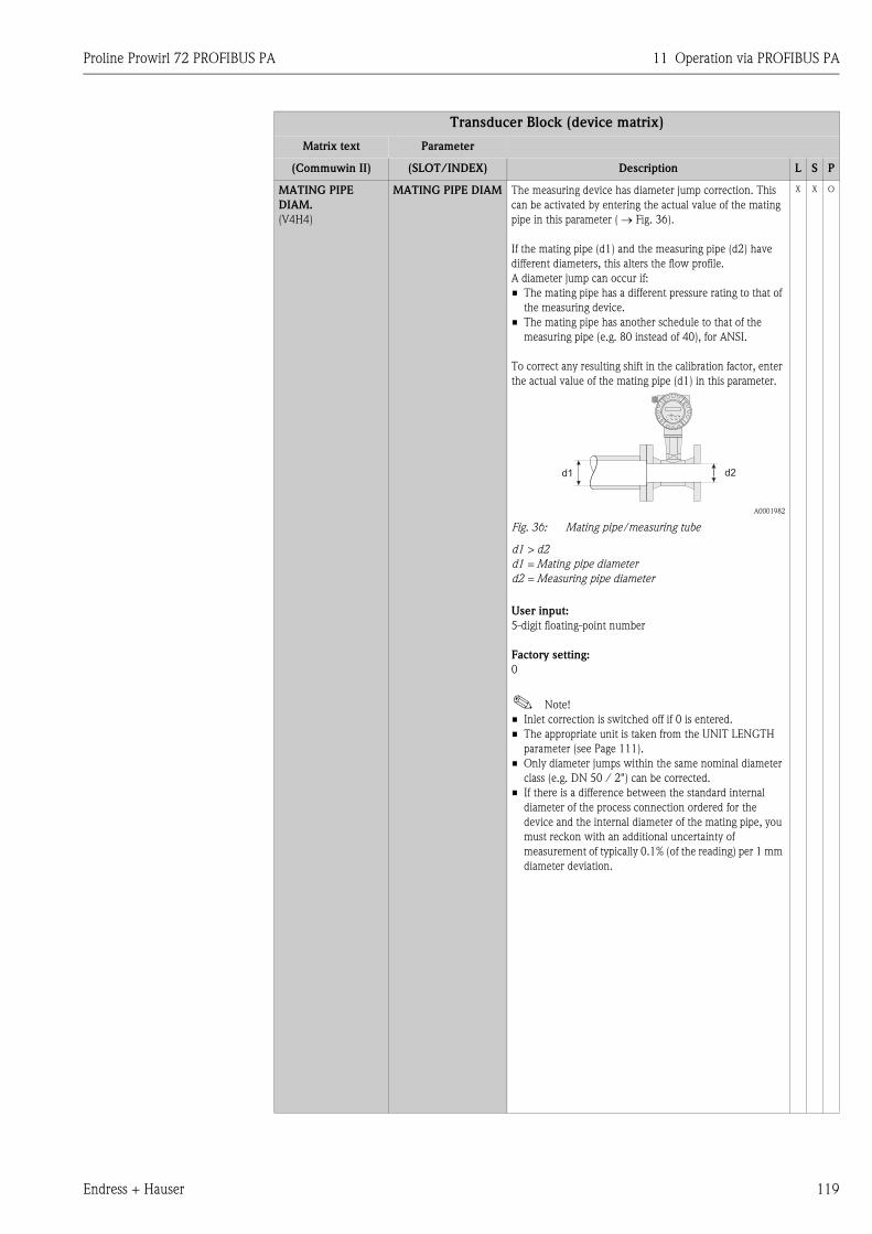
Proline Prowirl 72 PROFIBUS PA 11 Operation via PROFIBUS PA
Endress + Hauser 119
MATING PIPE
DIAM.
(V4H4)
MATING PIPE DIAM The measuring device has diameter jump correction. This
can be activated by entering the actual value of the mating
pipe in this parameter ( → Fig. 36).
If the mating pipe (d1) and the measuring pipe (d2) have
different diameters, this alters the flow profile.
A diameter jump can occur if:
• The mating pipe has a different pressure rating to that of
the measuring device.
• The mating pipe has another schedule to that of the
measuring pipe (e.g. 80 instead of 40), for ANSI.
To correct any resulting shift in the calibration factor, enter
the actual value of the mating pipe (d1) in this parameter.
A0001982
Fig. 36: Mating pipe/measuring tube
d1 > d2
d1 = Mating pipe diameter
d2 = Measuring pipe diameter
User input:
5-digit floating-point number
Factory setting:
0
! Note!
• Inlet correction is switched off if 0 is entered.
• The appropriate unit is taken from the UNIT LENGTH
parameter (see Page 111).
• Only diameter jumps within the same nominal diameter
class (e.g. DN 50 / 2") can be corrected.
• If there is a difference between the standard internal
diameter of the process connection ordered for the
device and the internal diameter of the mating pipe, you
must reckon with an additional uncertainty of
measurement of typically 0.1% (of the reading) per 1 mm
diameter deviation.
X X O
Transducer Block (device matrix)
Matrix text Parameter
(Commuwin II) (SLOT/INDEX) Description L S P
d2d1
Esc
E- +
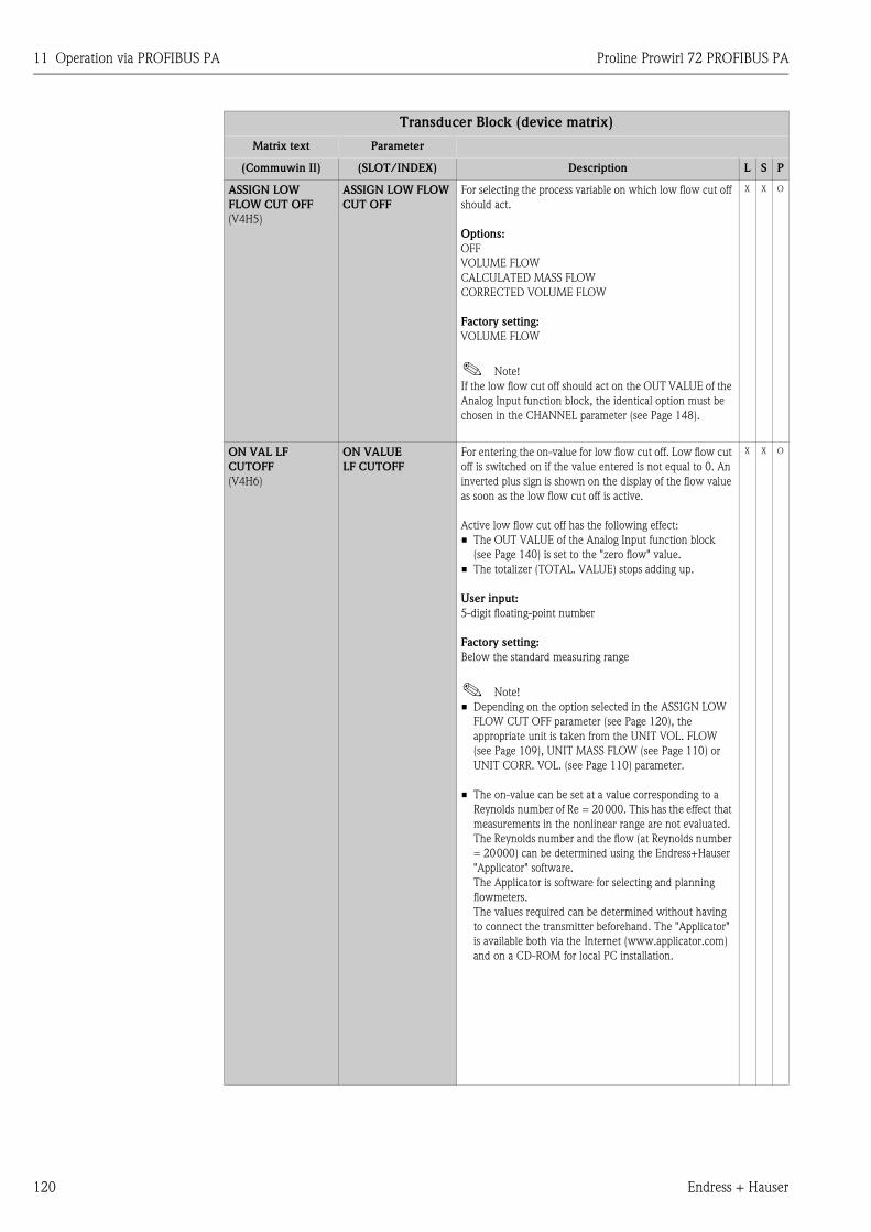
11 Operation via PROFIBUS PA Proline Prowirl 72 PROFIBUS PA
120 Endress + Hauser
ASSIGN LOW
FLOW CUT OFF
(V4H5)
ASSIGN LOW FLOW
CUT OFF
For selecting the process variable on which low flow cut off
should act.
Options:
OFF
VOLUME FLOW
CALCULATED MASS FLOW
CORRECTED VOLUME FLOW
Factory setting:
VOLUME FLOW
! Note!
If the low flow cut off should act on the OUT VALUE of the
Analog Input function block, the identical option must be
chosen in the CHANNEL parameter (see Page 148).
X X O
ON VAL LF
CUTOFF
(V4H6)
ON VALUE
LF CUTOFF
For entering the on-value for low flow cut off. Low flow cut
off is switched on if the value entered is not equal to 0. An
inverted plus sign is shown on the display of the flow value
as soon as the low flow cut off is active.
Active low flow cut off has the following effect:
• The OUT VALUE of the Analog Input function block
(see Page 140) is set to the "zero flow" value.
• The totalizer (TOTAL. VALUE) stops adding up.
User input:
5-digit floating-point number
Factory setting:
Below the standard measuring range
! Note!
• Depending on the option selected in the ASSIGN LOW
FLOW CUT OFF parameter (see Page 120), the
appropriate unit is taken from the UNIT VOL. FLOW
(see Page 109), UNIT MASS FLOW (see Page 110) or
UNIT CORR. VOL. (see Page 110) parameter.
• The on-value can be set at a value corresponding to a
Reynolds number of Re = 20000. This has the effect that
measurements in the nonlinear range are not evaluated.
The Reynolds number and the flow (at Reynolds number
= 20000) can be determined using the Endress+Hauser
"Applicator" software.
The Applicator is software for selecting and planning
flowmeters.
The values required can be determined without having
to connect the transmitter beforehand. The "Applicator"
is available both via the Internet (www.applicator.com)
and on a CD-ROM for local PC installation.
X X O
Transducer Block (device matrix)
Matrix text Parameter
(Commuwin II) (SLOT/INDEX) Description L S P
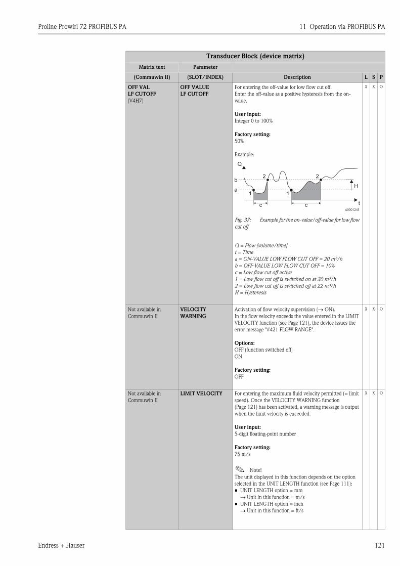
Proline Prowirl 72 PROFIBUS PA 11 Operation via PROFIBUS PA
Endress + Hauser 121
OFF VAL
LF CUTOFF
(V4H7)
OFF VALUE
LF CUTOFF
For entering the off-value for low flow cut off.
Enter the off-value as a positive hysteresis from the on-
value.
User input:
Integer 0 to 100%
Factory setting:
50%
Example:
Fig. 37: Example for the on-value/off-value for low flow
cut off
Q = Flow [volume/time]
t = Time
a = ON-VALUE LOW FLOW CUT OFF = 20 m³/h
b = OFF-VALUE LOW FLOW CUT OFF = 10%
c = Low flow cut off active
1 = Low flow cut off is switched on at 20 m³/h
2 = Low flow cut off is switched off at 22 m³/h
H = Hysteresis
X X O
Not available in
Commuwin II
VELOCITY
WARNING
Activation of flow velocity supervision (→ ON).
In the flow velocity exceeds the value entered in the LIMIT
VELOCITY function (see Page 121), the device issues the
error message "#421 FLOW RANGE".
Options:
OFF (function switched off)
ON
Factory setting:
OFF
X X O
Not available in
Commuwin II
LIMIT VELOCITY For entering the maximum fluid velocity permitted (= limit
speed). Once the VELOCITY WARNING function
(Page 121) has been activated, a warning message is output
when the limit velocity is exceeded.
User input:
5-digit floating-point number
Factory setting:
75 m/s
! Note!
The unit displayed in this function depends on the option
selected in the UNIT LENGTH function (see Page 111):
• UNIT LENGTH option = mm
→ Unit in this function = m/s
• UNIT LENGTH option = inch
→ Unit in this function = ft/s
X X O
Transducer Block (device matrix)
Matrix text Parameter
(Commuwin II) (SLOT/INDEX) Description L S P
1
c c
Q
t
1
2b
a
2
H
A0001245
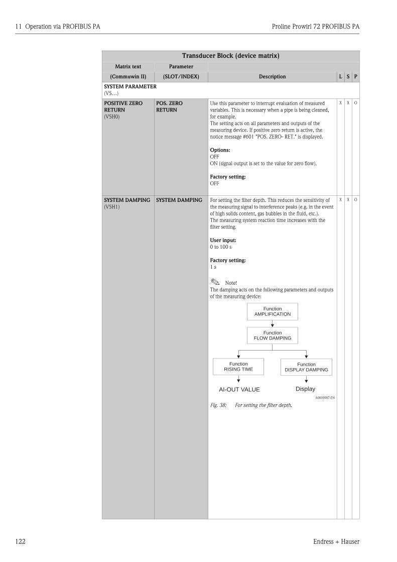
11 Operation via PROFIBUS PA Proline Prowirl 72 PROFIBUS PA
122 Endress + Hauser
SYSTEM PARAMETER
(V5…)
POSITIVE ZERO
RETURN
(V5H0)
POS. ZERO
RETURN
Use this parameter to interrupt evaluation of measured
variables. This is necessary when a pipe is being cleaned,
for example.
The setting acts on all parameters and outputs of the
measuring device. If positive zero return is active, the
notice message #601 "POS. ZERO- RET." is displayed.
Options:
OFF
ON (signal output is set to the value for zero flow).
Factory setting:
OFF
X X O
SYSTEM DAMPING
(V5H1)
SYSTEM DAMPING For setting the filter depth. This reduces the sensitivity of
the measuring signal to interference peaks (e.g. in the event
of high solids content, gas bubbles in the fluid, etc.).
The measuring system reaction time increases with the
filter setting.
User input:
0 to 100 s
Factory setting:
1 s
! Note!
The damping acts on the following parameters and outputs
of the measuring device:
A0003907-EN
Fig. 38: For setting the filter depth.
X X O
Transducer Block (device matrix)
Matrix text Parameter
(Commuwin II) (SLOT/INDEX) Description L S P
FunctionFLOW DAMPING
FunctionAMPLIFICATION
Display
FunctionRISING TIME
AI-OUT VALUE
FunctionDISPLAY DAMPING
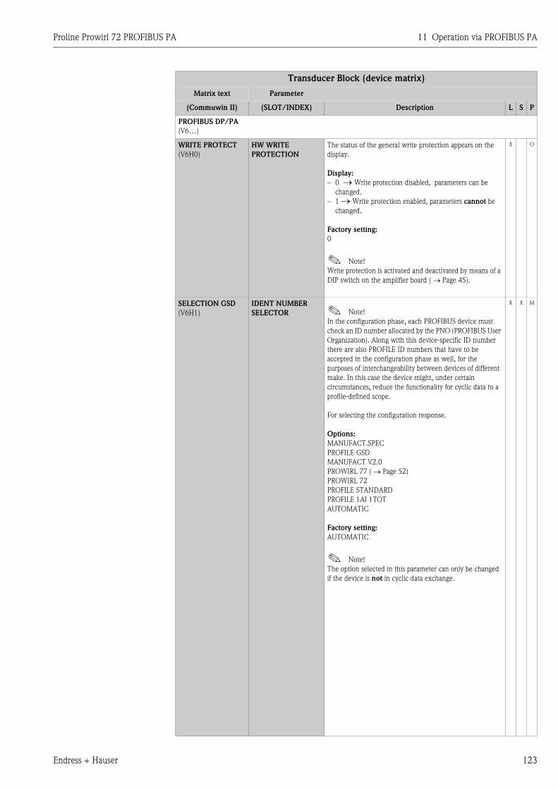
Proline Prowirl 72 PROFIBUS PA 11 Operation via PROFIBUS PA
Endress + Hauser 123
PROFIBUS DP/PA
(V6…)
WRITE PROTECT
(V6H0)
HW WRITE
PROTECTION
The status of the general write protection appears on the
display.
Display:
– 0 → Write protection disabled, parameters can be
changed.
– 1 → Write protection enabled, parameters cannot be
changed.
Factory setting:
0
! Note!
Write protection is activated and deactivated by means of a
DIP switch on the amplifier board ( → Page 45).
X O
SELECTION GSD
(V6H1)
IDENT NUMBER
SELECTOR ! Note!
In the configuration phase, each PROFIBUS device must
check an ID number allocated by the PNO (PROFIBUS User
Organization). Along with this device-specific ID number
there are also PROFILE ID numbers that have to be
accepted in the configuration phase as well, for the
purposes of interchangeability between devices of different
make. In this case the device might, under certain
circumstances, reduce the functionality for cyclic data to a
profile-defined scope.
For selecting the configuration response.
Options:
MANUFACT.SPEC
PROFILE GSD
MANUFACT V2.0
PROWIRL 77 ( → Page 52)
PROWIRL 72
PROFILE STANDARD
PROFILE 1AI 1TOT
AUTOMATIC
Factory setting:
AUTOMATIC
! Note!
The option selected in this parameter can only be changed
if the device is not in cyclic data exchange.
X X M
Transducer Block (device matrix)
Matrix text Parameter
(Commuwin II) (SLOT/INDEX) Description L S P
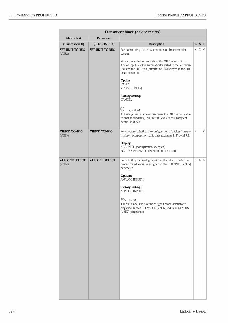
11 Operation via PROFIBUS PA Proline Prowirl 72 PROFIBUS PA
124 Endress + Hauser
SET UNIT TO BUS
(V6H2)
SET UNIT TO BUS For transmitting the set system units to the automation
system.
When transmission takes place, the OUT value in the
Analog Input Block is automatically scaled to the set system
unit and the OUT unit (output unit) is displayed in the OUT
UNIT parameter.
Option
CANCEL
YES (SET UNITS)
Factory setting:
CANCEL
" Caution!
Activating this parameter can cause the OUT output value
to change suddenly; this, in turn, can affect subsequent
control routines.
X X O
CHECK CONFIG.
(V6H3)
CHECK CONFIG For checking whether the configuration of a Class 1 master
has been accepted for cyclic data exchange in Prowirl 72.
Display:
ACCEPTED (configuration accepted)
NOT ACCEPTED (configuration not accepted)
X O
AI BLOCK SELECT
(V6H4)
AI BLOCK SELECT For selecting the Analog Input function block to which a
process variable can be assigned in the CHANNEL (V6H5)
parameter.
Options:
ANALOG INPUT 1
Factory setting:
ANALOG INPUT 1
! Note!
The value and status of the assigned process variable is
displayed in the OUT VALUE (V6H6) and OUT STATUS
(V6H7) parameters.
X X O
Transducer Block (device matrix)
Matrix text Parameter
(Commuwin II) (SLOT/INDEX) Description L S P
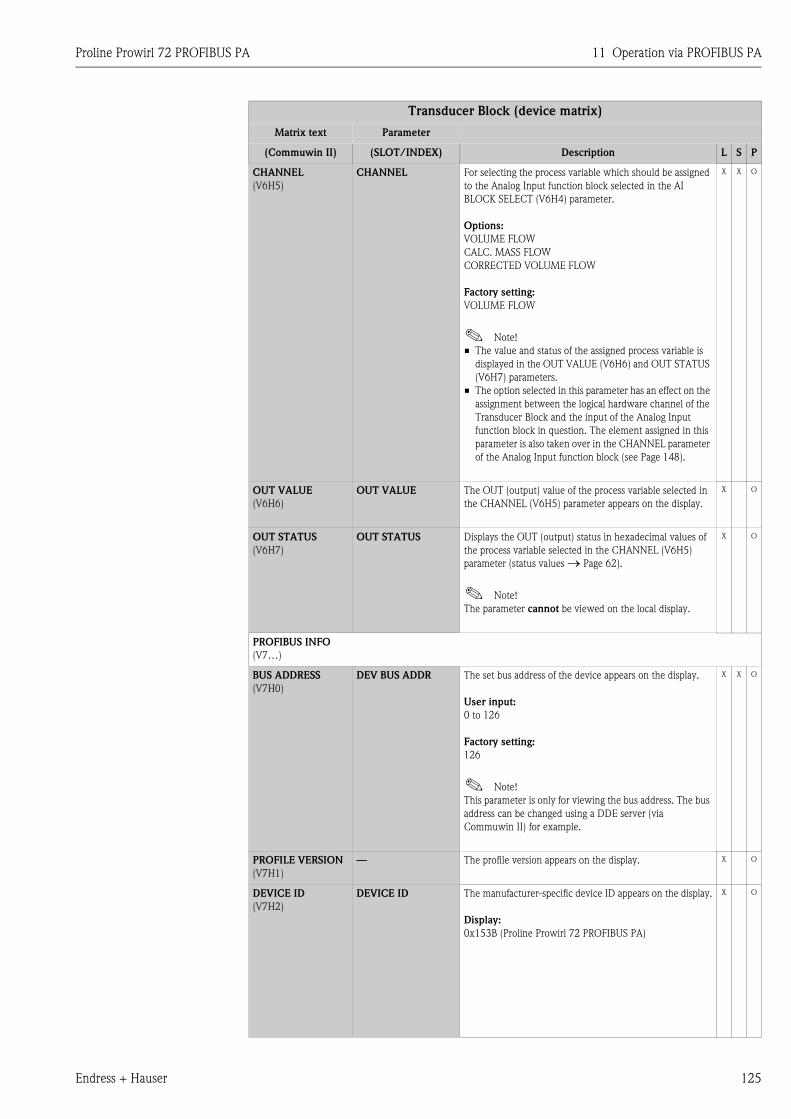
Proline Prowirl 72 PROFIBUS PA 11 Operation via PROFIBUS PA
Endress + Hauser 125
CHANNEL
(V6H5)
CHANNEL For selecting the process variable which should be assigned
to the Analog Input function block selected in the AI
BLOCK SELECT (V6H4) parameter.
Options:
VOLUME FLOW
CALC. MASS FLOW
CORRECTED VOLUME FLOW
Factory setting:
VOLUME FLOW
! Note!
• The value and status of the assigned process variable is
displayed in the OUT VALUE (V6H6) and OUT STATUS
(V6H7) parameters.
• The option selected in this parameter has an effect on the
assignment between the logical hardware channel of the
Transducer Block and the input of the Analog Input
function block in question. The element assigned in this
parameter is also taken over in the CHANNEL parameter
of the Analog Input function block (see Page 148).
X X O
OUT VALUE
(V6H6)
OUT VALUE The OUT (output) value of the process variable selected in
the CHANNEL (V6H5) parameter appears on the display.
X O
OUT STATUS
(V6H7)
OUT STATUS Displays the OUT (output) status in hexadecimal values of
the process variable selected in the CHANNEL (V6H5)
parameter (status values → Page 62).
! Note!
The parameter cannot be viewed on the local display.
X O
PROFIBUS INFO
(V7…)
BUS ADDRESS
(V7H0)
DEV BUS ADDR The set bus address of the device appears on the display.
User input:
0 to 126
Factory setting:
126
! Note!
This parameter is only for viewing the bus address. The bus
address can be changed using a DDE server (via
Commuwin II) for example.
X X O
PROFILE VERSION
(V7H1)
— The profile version appears on the display. X O
DEVICE ID
(V7H2)
DEVICE ID The manufacturer-specific device ID appears on the display.
Display:
0x153B (Proline Prowirl 72 PROFIBUS PA)
X O
Transducer Block (device matrix)
Matrix text Parameter
(Commuwin II) (SLOT/INDEX) Description L S P
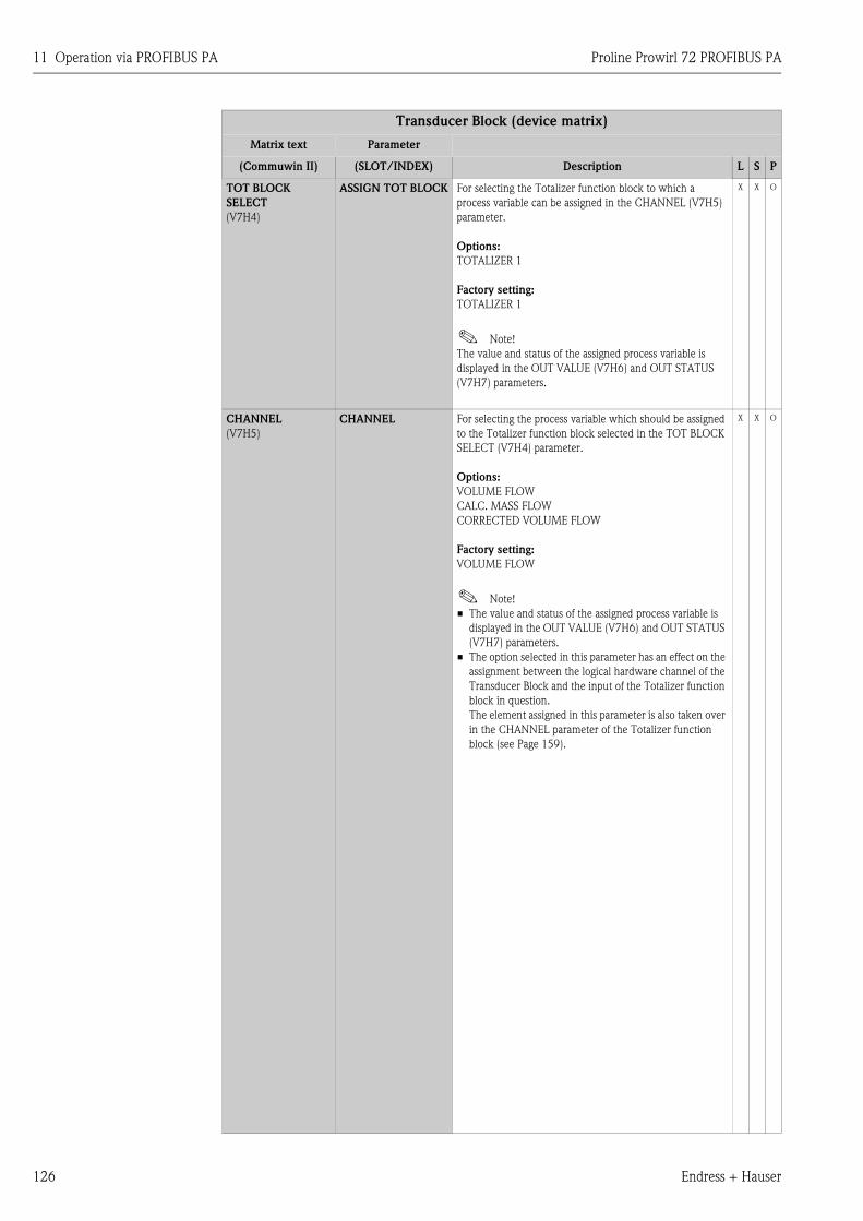
11 Operation via PROFIBUS PA Proline Prowirl 72 PROFIBUS PA
126 Endress + Hauser
TOT BLOCK
SELECT
(V7H4)
ASSIGN TOT BLOCK For selecting the Totalizer function block to which a
process variable can be assigned in the CHANNEL (V7H5)
parameter.
Options:
TOTALIZER 1
Factory setting:
TOTALIZER 1
! Note!
The value and status of the assigned process variable is
displayed in the OUT VALUE (V7H6) and OUT STATUS
(V7H7) parameters.
X X O
CHANNEL
(V7H5)
CHANNEL For selecting the process variable which should be assigned
to the Totalizer function block selected in the TOT BLOCK
SELECT (V7H4) parameter.
Options:
VOLUME FLOW
CALC. MASS FLOW
CORRECTED VOLUME FLOW
Factory setting:
VOLUME FLOW
! Note!
• The value and status of the assigned process variable is
displayed in the OUT VALUE (V7H6) and OUT STATUS
(V7H7) parameters.
• The option selected in this parameter has an effect on the
assignment between the logical hardware channel of the
Transducer Block and the input of the Totalizer function
block in question.
The element assigned in this parameter is also taken over
in the CHANNEL parameter of the Totalizer function
block (see Page 159).
X X O
Transducer Block (device matrix)
Matrix text Parameter
(Commuwin II) (SLOT/INDEX) Description L S P
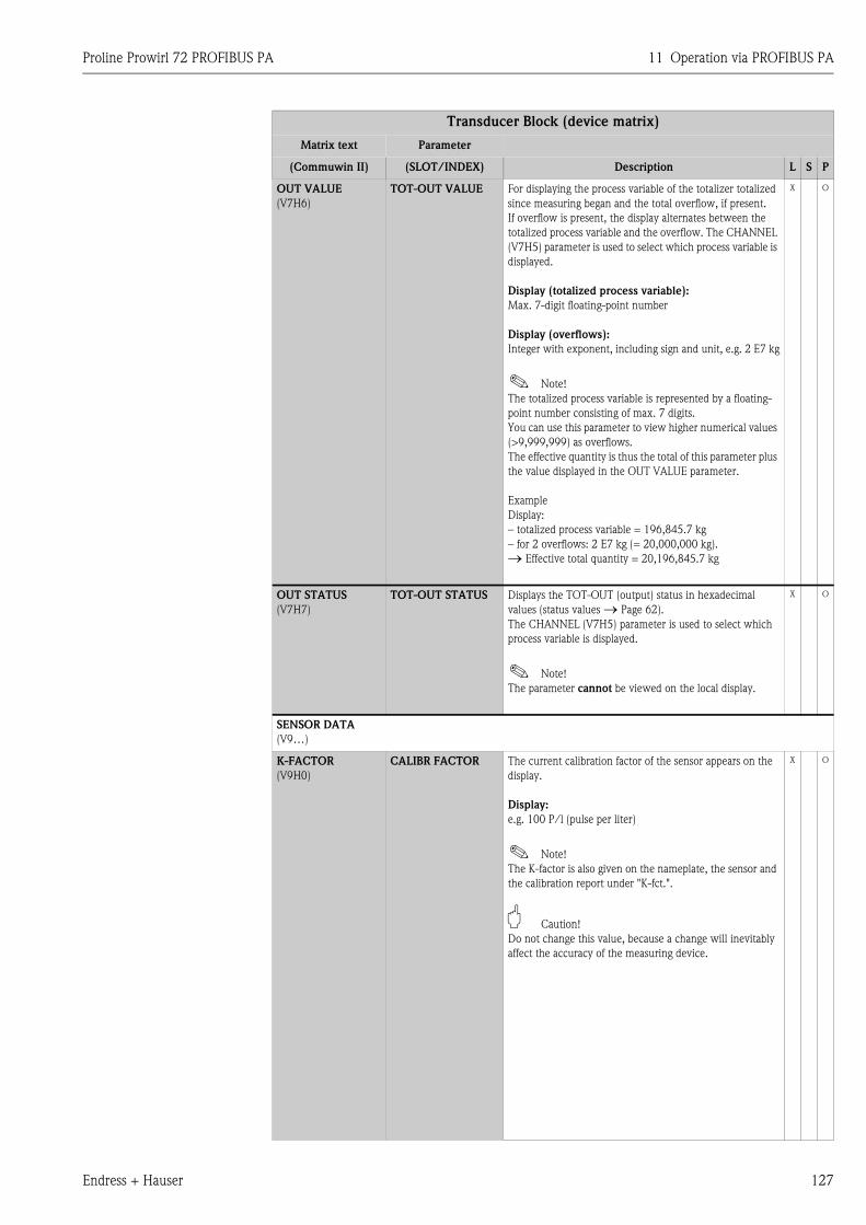
Proline Prowirl 72 PROFIBUS PA 11 Operation via PROFIBUS PA
Endress + Hauser 127
OUT VALUE
(V7H6)
TOT-OUT VALUE For displaying the process variable of the totalizer totalized
since measuring began and the total overflow, if present.
If overflow is present, the display alternates between the
totalized process variable and the overflow. The CHANNEL
(V7H5) parameter is used to select which process variable is
displayed.
Display (totalized process variable):
Max. 7-digit floating-point number
Display (overflows):
Integer with exponent, including sign and unit, e.g. 2 E7 kg
! Note!
The totalized process variable is represented by a floating-
point number consisting of max. 7 digits.
You can use this parameter to view higher numerical values
(>9,999,999) as overflows.
The effective quantity is thus the total of this parameter plus
the value displayed in the OUT VALUE parameter.
Example
Display:
– totalized process variable = 196,845.7 kg
– for 2 overflows: 2 E7 kg (= 20,000,000 kg).
→ Effective total quantity = 20,196,845.7 kg
X O
OUT STATUS
(V7H7)
TOT-OUT STATUS Displays the TOT-OUT (output) status in hexadecimal
values (status values → Page 62).
The CHANNEL (V7H5) parameter is used to select which
process variable is displayed.
! Note!
The parameter cannot be viewed on the local display.
X O
SENSOR DATA
(V9…)
K-FACTOR
(V9H0)
CALIBR FACTOR The current calibration factor of the sensor appears on the
display.
Display:
e.g. 100 P/l (pulse per liter)
! Note!
The K-factor is also given on the nameplate, the sensor and
the calibration report under "K-fct.".
" Caution!
Do not change this value, because a change will inevitably
affect the accuracy of the measuring device.
X O
Transducer Block (device matrix)
Matrix text Parameter
(Commuwin II) (SLOT/INDEX) Description L S P
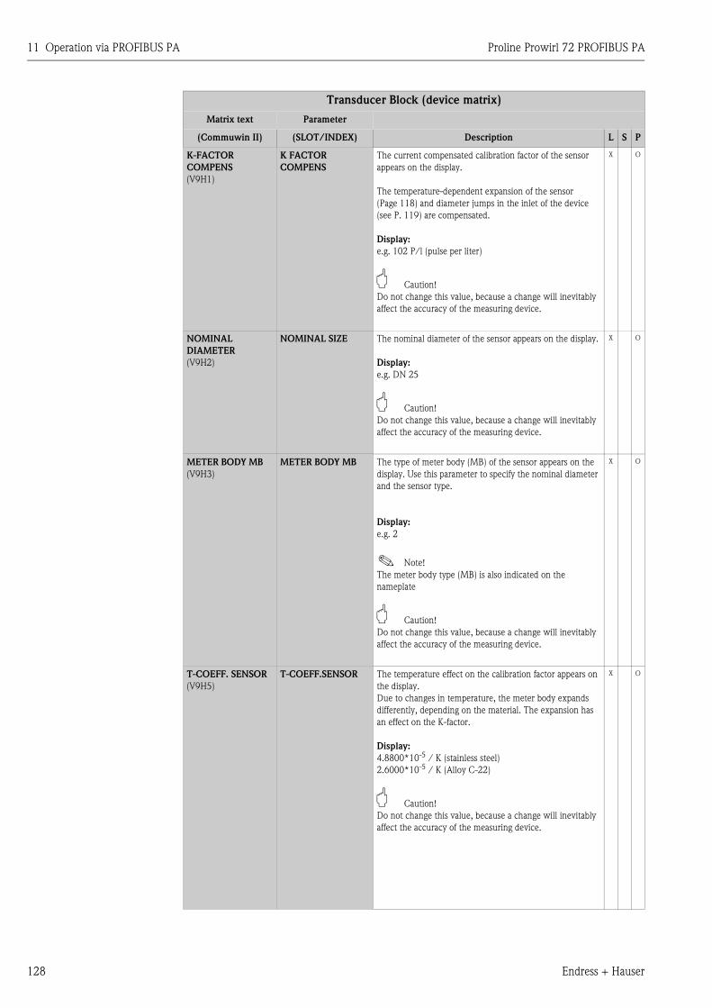
11 Operation via PROFIBUS PA Proline Prowirl 72 PROFIBUS PA
128 Endress + Hauser
K-FACTOR
COMPENS
(V9H1)
K FACTOR
COMPENS
The current compensated calibration factor of the sensor
appears on the display.
The temperature-dependent expansion of the sensor
(Page 118) and diameter jumps in the inlet of the device
(see P. 119) are compensated.
Display:
e.g. 102 P/l (pulse per liter)
" Caution!
Do not change this value, because a change will inevitably
affect the accuracy of the measuring device.
X O
NOMINAL
DIAMETER
(V9H2)
NOMINAL SIZE The nominal diameter of the sensor appears on the display.
Display:
e.g. DN 25
" Caution!
Do not change this value, because a change will inevitably
affect the accuracy of the measuring device.
X O
METER BODY MB
(V9H3)
METER BODY MB The type of meter body (MB) of the sensor appears on the
display. Use this parameter to specify the nominal diameter
and the sensor type.
Display:
e.g. 2
! Note!
The meter body type (MB) is also indicated on the
nameplate
" Caution!
Do not change this value, because a change will inevitably
affect the accuracy of the measuring device.
X O
T-COEFF. SENSOR
(V9H5)
T-COEFF.SENSOR The temperature effect on the calibration factor appears on
the display.
Due to changes in temperature, the meter body expands
differently, depending on the material. The expansion has
an effect on the K-factor.
Display:
4.8800*10-5 / K (stainless steel)
2.6000*10-5 / K (Alloy C-22)
" Caution!
Do not change this value, because a change will inevitably
affect the accuracy of the measuring device.
X O
Transducer Block (device matrix)
Matrix text Parameter
(Commuwin II) (SLOT/INDEX) Description L S P
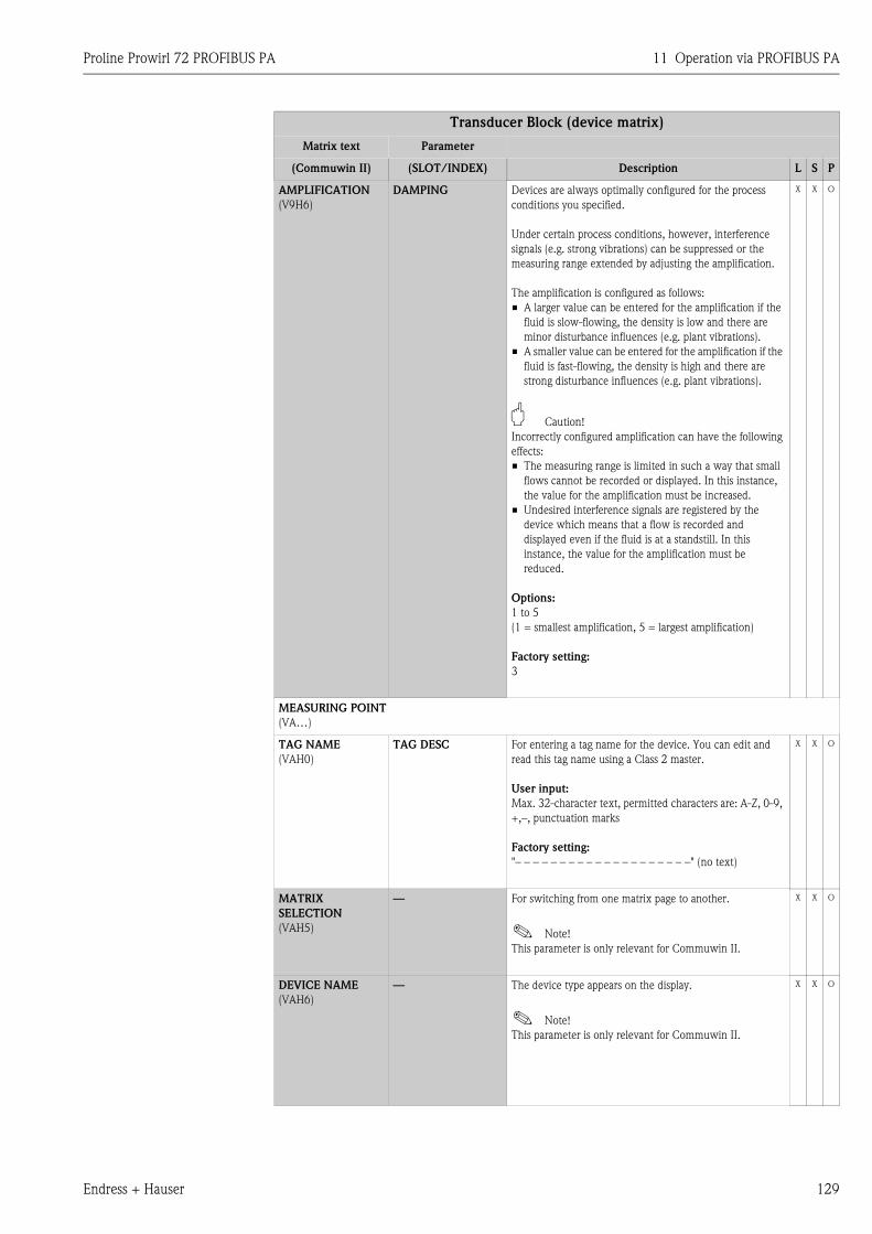
Proline Prowirl 72 PROFIBUS PA 11 Operation via PROFIBUS PA
Endress + Hauser 129
AMPLIFICATION
(V9H6)
DAMPING Devices are always optimally configured for the process
conditions you specified.
Under certain process conditions, however, interference
signals (e.g. strong vibrations) can be suppressed or the
measuring range extended by adjusting the amplification.
The amplification is configured as follows:
• A larger value can be entered for the amplification if the
fluid is slow-flowing, the density is low and there are
minor disturbance influences (e.g. plant vibrations).
• A smaller value can be entered for the amplification if the
fluid is fast-flowing, the density is high and there are
strong disturbance influences (e.g. plant vibrations).
" Caution!
Incorrectly configured amplification can have the following
effects:
• The measuring range is limited in such a way that small
flows cannot be recorded or displayed. In this instance,
the value for the amplification must be increased.
• Undesired interference signals are registered by the
device which means that a flow is recorded and
displayed even if the fluid is at a standstill. In this
instance, the value for the amplification must be
reduced.
Options:
1 to 5
(1 = smallest amplification, 5 = largest amplification)
Factory setting:
3
X X O
MEASURING POINT
(VA…)
TAG NAME
(VAH0)
TAG DESC For entering a tag name for the device. You can edit and
read this tag name using a Class 2 master.
User input:
Max. 32-character text, permitted characters are: A-Z, 0-9,
+,–, punctuation marks
Factory setting:
"– – – – – – – – – – – – – – – – – – – –" (no text)
X X O
MATRIX
SELECTION
(VAH5)
— For switching from one matrix page to another.
! Note!
This parameter is only relevant for Commuwin II.
X X O
DEVICE NAME
(VAH6)
— The device type appears on the display.
! Note!
This parameter is only relevant for Commuwin II.
X X O
Transducer Block (device matrix)
Matrix text Parameter
(Commuwin II) (SLOT/INDEX) Description L S P
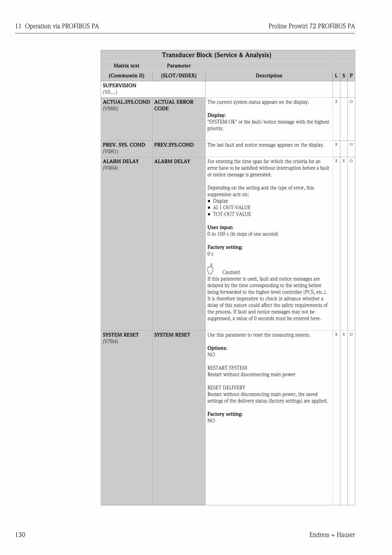
11 Operation via PROFIBUS PA Proline Prowirl 72 PROFIBUS PA
130 Endress + Hauser
Transducer Block (Service & Analysis)
Matrix text Parameter
(Commuwin II) (SLOT/INDEX) Description L S P
SUPERVISION
(V0…)
ACTUAL.SYS.COND
(V0H0)
ACTUAL ERROR
CODE
The current system status appears on the display.
Display:
"SYSTEM OK" or the fault/notice message with the highest
priority.
X O
PREV. SYS. COND
(V0H1)
PREV.SYS.COND The last fault and notice message appears on the display. X O
ALARM DELAY
(V0H4)
ALARM DELAY For entering the time span for which the criteria for an
error have to be satisfied without interruption before a fault
or notice message is generated.
Depending on the setting and the type of error, this
suppression acts on:
• Display
• AI 1 OUT-VALUE
• TOT-OUT VALUE
User input:
0 to 100 s (in steps of one second)
Factory setting:
0 s
" Caution!
If this parameter is used, fault and notice messages are
delayed by the time corresponding to the setting before
being forwarded to the higher-level controller (PCS, etc.).
It is therefore imperative to check in advance whether a
delay of this nature could affect the safety requirements of
the process. If fault and notice messages may not be
suppressed, a value of 0 seconds must be entered here.
X X O
SYSTEM RESET
(V7H4)
SYSTEM RESET Use this parameter to reset the measuring system.
Options:
NO
RESTART SYSTEM
Restart without disconnecting main power
RESET DELIVERY
Restart without disconnecting main power, the saved
settings of the delivery status (factory settings) are applied.
Factory setting:
NO
X X O
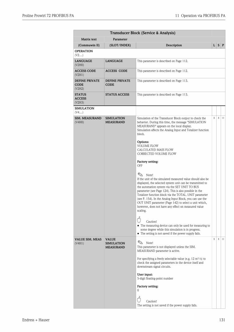
Proline Prowirl 72 PROFIBUS PA 11 Operation via PROFIBUS PA
Endress + Hauser 131
OPERATION
(V2…)
LANGUAGE
(V2H0)
LANGUAGE This parameter is described on Page 112.
ACCESS CODE
(V2H1)
ACCESS CODE This parameter is described on Page 112.
DEFINE PRIVATE
CODE
(V2H2)
DEFINE PRIVATE
CODE
This parameter is described on Page 113.
STATUS
ACCESS
(V2H3)
STATUS ACCESS This parameter is described on Page 113.
SIMULATION
(V4…)
SIM. MEASURAND
(V4H0)
SIMULATION
MEASURAND
Simulation of the Transducer Block output to check the
behavior. During this time, the message "SIMULATION
MEASURAND" appears on the local display.
Simulation affects the Analog Input and Totalizer function
block.
Options:
VOLUME FLOW
CALCULATED MASS FLOW
CORRECTED VOLUME FLOW
Factory setting:
OFF
! Note!
If the unit of the simulated measured value should also be
displayed, the selected system unit can be transmitted to
the automation system via the SET UNIT TO BUS
parameter (see Page 124). This is also possible in the
Totalizer function block via the TOTAL. UNIT parameter
(see P. 154). In the Analog Input Block, you can use the
OUT UNIT parameter (Page 142) to select a unit which,
however, does not have any effect on measured value
scaling.
" Caution!
• The measuring device can only be used for measuring to
some degree while this simulation is in progress.
• The setting is not saved if the power supply fails.
X X O
VALUE SIM. MEAS
(V4H1)
VALUE
SIMULATION
MEASURAND
! Note!
This parameter is not displayed unless the SIM.
MEASURAND parameter is active.
For specifying a freely selectable value (e.g. 12 m³/s) to
check the assigned parameters in the device itself and
downstream signal circuits.
User input:
5-digit floating-point number
Factory setting:
0
" Caution!
The setting is not saved if the power supply fails.
X X O
Transducer Block (Service & Analysis)
Matrix text Parameter
(Commuwin II) (SLOT/INDEX) Description L S P
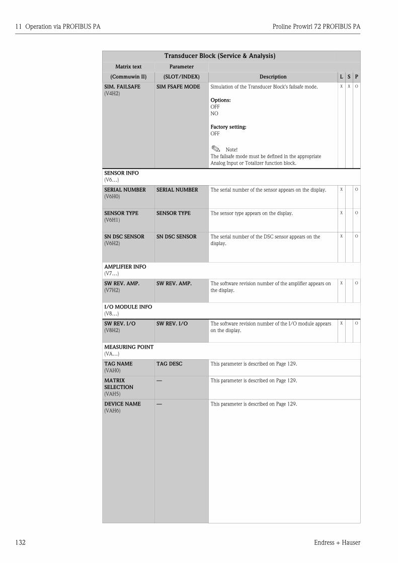
11 Operation via PROFIBUS PA Proline Prowirl 72 PROFIBUS PA
132 Endress + Hauser
SIM. FAILSAFE
(V4H2)
SIM FSAFE MODE Simulation of the Transducer Block's failsafe mode.
Options:
OFF
NO
Factory setting:
OFF
! Note!
The failsafe mode must be defined in the appropriate
Analog Input or Totalizer function block.
X X O
SENSOR INFO
(V6…)
SERIAL NUMBER
(V6H0)
SERIAL NUMBER The serial number of the sensor appears on the display. X O
SENSOR TYPE
(V6H1)
SENSOR TYPE The sensor type appears on the display. X O
SN DSC SENSOR
(V6H2)
SN DSC SENSOR The serial number of the DSC sensor appears on the
display.
X O
AMPLIFIER INFO
(V7…)
SW REV. AMP.
(V7H2)
SW REV. AMP. The software revision number of the amplifier appears on
the display.
X O
I/O MODULE INFO
(V8…)
SW REV. I/O
(V8H2)
SW REV. I/O The software revision number of the I/O module appears
on the display.
X O
MEASURING POINT
(VA…)
TAG NAME
(VAH0)
TAG DESC This parameter is described on Page 129.
MATRIX
SELECTION
(VAH5)
— This parameter is described on Page 129.
DEVICE NAME
(VAH6)
— This parameter is described on Page 129.
Transducer Block (Service & Analysis)
Matrix text Parameter
(Commuwin II) (SLOT/INDEX) Description L S P
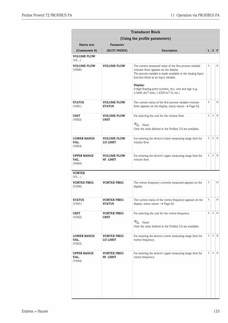
Proline Prowirl 72 PROFIBUS PA 11 Operation via PROFIBUS PA
Endress + Hauser 133
Transducer Block
(Using the profile parameters)
Matrix text Parameter
(Commuwin II) (SLOT/INDEX) Description L S P
VOLUME FLOW
(V0…)
VOLUME FLOW
(V0H0)
VOLUME FLOW The current measured value of the first process variable
(volume flow) appears on the display.
The process variable is made available to the Analog Input
function block as an input variable.
Display:
5-digit floating point number, incl. unit and sign (e.g.
5.5445 dm3/min; 1.4359 m3/h; etc.)
X M
STATUS
(V0H1)
VOLUME FLOW
STATUS
The current status of the first process variable (volume
flow) appears on the display, status values → Page 62.
X M
UNIT
(V0H2)
VOLUME FLOW
UNIT
For selecting the unit for the volume flow.
! Note!
Only the units defined in the Profiles 3.0 are available.
X X M
LOWER RANGE
VAL.
(V0H3)
VOLUME FLOW
LO LIMIT
For entering the device's lower measuring range limit for
volume flow.
X X M
UPPER RANGE
VAL.
(V0H4)
VOLUME FLOW
HI LIMIT
For entering the device's upper measuring range limit for
volume flow.
X X M
VORTEX
(V5…)
VORTEX FREQ
(V5H0)
VORTEX FREQ The vortex frequency currently measured appears on the
display.
X M
STATUS
(V5H1)
VORTEX FREQ
STATUS
The current status of the vortex frequency appears on the
display, status values → Page 62.
X M
UNIT
(V5H2)
VORTEX FREQ
UNIT
For selecting the unit for the vortex frequency.
! Note!
Only the units defined in the Profiles 3.0 are available.
X X M
LOWER RANGE
VAL.
(V5H3)
VORTEX FREQ
LO LIMIT
For entering the device's lower measuring range limit for
vortex frequency.
X X M
UPPER RANGE
VAL.
(V5H4)
VORTEX FREQ
HI LIMIT
For entering the device's upper measuring range limit for
vortex frequency.
X X M
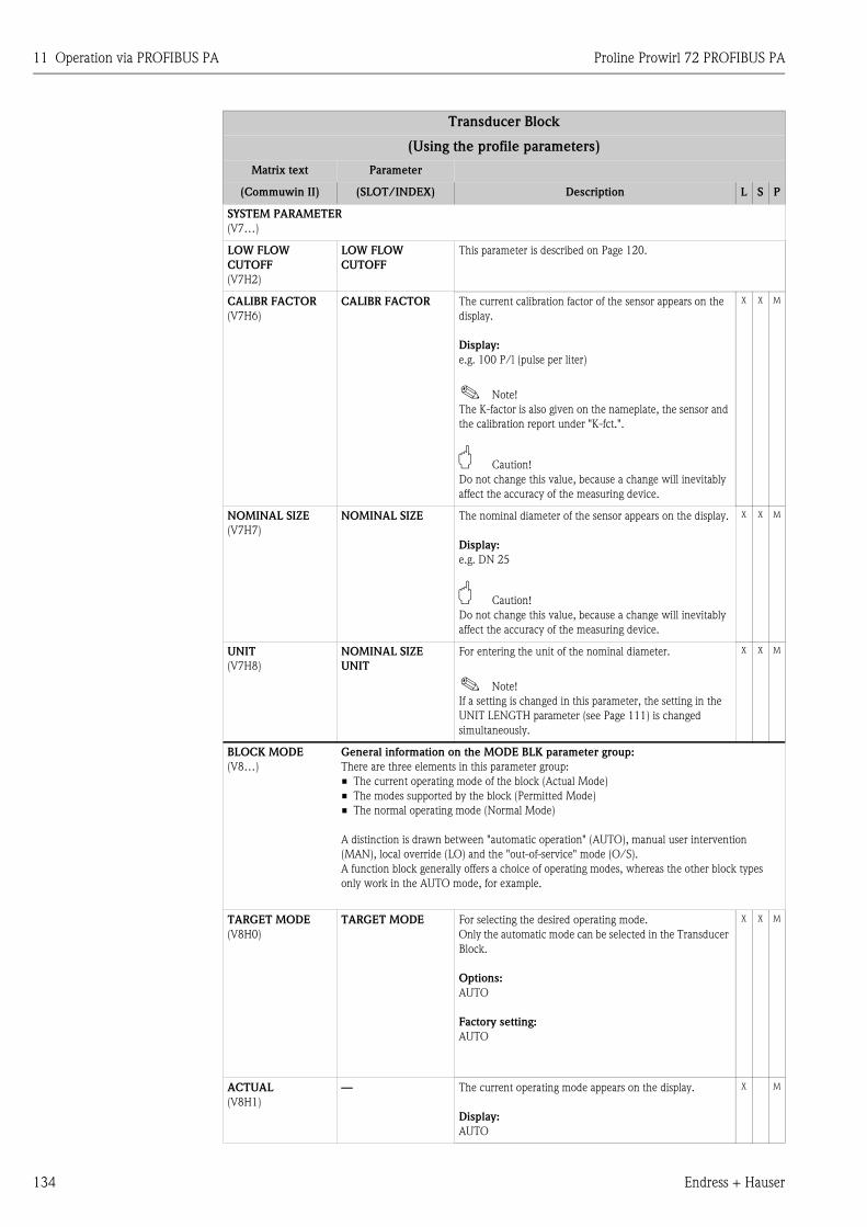
11 Operation via PROFIBUS PA Proline Prowirl 72 PROFIBUS PA
134 Endress + Hauser
SYSTEM PARAMETER
(V7…)
LOW FLOW
CUTOFF
(V7H2)
LOW FLOW
CUTOFF
This parameter is described on Page 120.
CALIBR FACTOR
(V7H6)
CALIBR FACTOR The current calibration factor of the sensor appears on the
display.
Display:
e.g. 100 P/l (pulse per liter)
! Note!
The K-factor is also given on the nameplate, the sensor and
the calibration report under "K-fct.".
" Caution!
Do not change this value, because a change will inevitably
affect the accuracy of the measuring device.
X X M
NOMINAL SIZE
(V7H7)
NOMINAL SIZE The nominal diameter of the sensor appears on the display.
Display:
e.g. DN 25
" Caution!
Do not change this value, because a change will inevitably
affect the accuracy of the measuring device.
X X M
UNIT
(V7H8)
NOMINAL SIZE
UNIT
For entering the unit of the nominal diameter.
! Note!
If a setting is changed in this parameter, the setting in the
UNIT LENGTH parameter (see Page 111) is changed
simultaneously.
X X M
BLOCK MODE
(V8…)
General information on the MODE BLK parameter group:
There are three elements in this parameter group:
• The current operating mode of the block (Actual Mode)
• The modes supported by the block (Permitted Mode)
• The normal operating mode (Normal Mode)
A distinction is drawn between "automatic operation" (AUTO), manual user intervention
(MAN), local override (LO) and the "out-of-service" mode (O/S).
A function block generally offers a choice of operating modes, whereas the other block types
only work in the AUTO mode, for example.
TARGET MODE
(V8H0)
TARGET MODE For selecting the desired operating mode.
Only the automatic mode can be selected in the Transducer
Block.
Options:
AUTO
Factory setting:
AUTO
X X M
ACTUAL
(V8H1)
— The current operating mode appears on the display.
Display:
AUTO
X M
Transducer Block
(Using the profile parameters)
Matrix text Parameter
(Commuwin II) (SLOT/INDEX) Description L S P
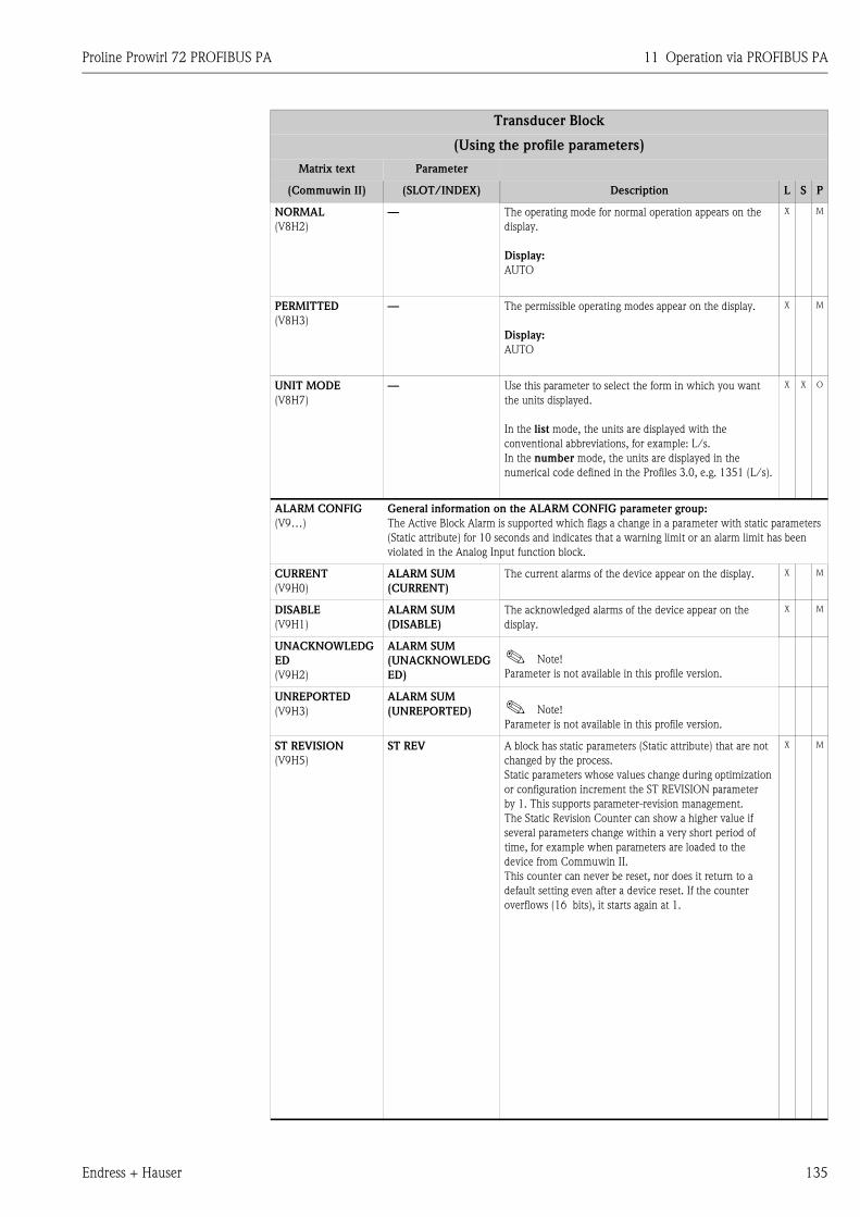
Proline Prowirl 72 PROFIBUS PA 11 Operation via PROFIBUS PA
Endress + Hauser 135
NORMAL
(V8H2)
— The operating mode for normal operation appears on the
display.
Display:
AUTO
X M
PERMITTED
(V8H3)
— The permissible operating modes appear on the display.
Display:
AUTO
X M
UNIT MODE
(V8H7)
— Use this parameter to select the form in which you want
the units displayed.
In the list mode, the units are displayed with the
conventional abbreviations, for example: L/s.
In the number mode, the units are displayed in the
numerical code defined in the Profiles 3.0, e.g. 1351 (L/s).
X X O
ALARM CONFIG
(V9…)
General information on the ALARM CONFIG parameter group:
The Active Block Alarm is supported which flags a change in a parameter with static parameters
(Static attribute) for 10 seconds and indicates that a warning limit or an alarm limit has been
violated in the Analog Input function block.
CURRENT
(V9H0)
ALARM SUM
(CURRENT)
The current alarms of the device appear on the display. X M
DISABLE
(V9H1)
ALARM SUM
(DISABLE)
The acknowledged alarms of the device appear on the
display.
X M
UNACKNOWLEDG
ED
(V9H2)
ALARM SUM
(UNACKNOWLEDG
ED)
! Note!
Parameter is not available in this profile version.
UNREPORTED
(V9H3)
ALARM SUM
(UNREPORTED) ! Note!
Parameter is not available in this profile version.
ST REVISION
(V9H5)
ST REV A block has static parameters (Static attribute) that are not
changed by the process.
Static parameters whose values change during optimization
or configuration increment the ST REVISION parameter
by 1. This supports parameter-revision management.
The Static Revision Counter can show a higher value if
several parameters change within a very short period of
time, for example when parameters are loaded to the
device from Commuwin II.
This counter can never be reset, nor does it return to a
default setting even after a device reset. If the counter
overflows (16 bits), it starts again at 1.
X M
Transducer Block
(Using the profile parameters)
Matrix text Parameter
(Commuwin II) (SLOT/INDEX) Description L S P
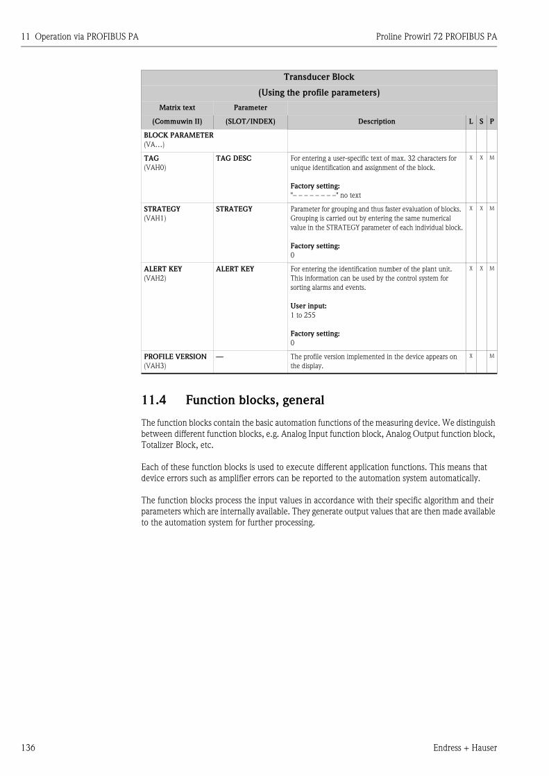
11 Operation via PROFIBUS PA Proline Prowirl 72 PROFIBUS PA
136 Endress + Hauser
11.4 Function blocks, general
The function blocks contain the basic automation functions of the measuring device. We distinguish
between different function blocks, e.g. Analog Input function block, Analog Output function block,
Totalizer Block, etc.
Each of these function blocks is used to execute different application functions. This means that
device errors such as amplifier errors can be reported to the automation system automatically.
The function blocks process the input values in accordance with their specific algorithm and their
parameters which are internally available. They generate output values that are then made available
to the automation system for further processing.
BLOCK PARAMETER
(VA…)
TAG
(VAH0)
TAG DESC For entering a user-specific text of max. 32 characters for
unique identification and assignment of the block.
Factory setting:
"– – – – – – – –" no text
X X M
STRATEGY
(VAH1)
STRATEGY Parameter for grouping and thus faster evaluation of blocks.
Grouping is carried out by entering the same numerical
value in the STRATEGY parameter of each individual block.
Factory setting:
0
X X M
ALERT KEY
(VAH2)
ALERT KEY For entering the identification number of the plant unit.
This information can be used by the control system for
sorting alarms and events.
User input:
1 to 255
Factory setting:
0
X X M
PROFILE VERSION
(VAH3)
— The profile version implemented in the device appears on
the display.
X M
Transducer Block
(Using the profile parameters)
Matrix text Parameter
(Commuwin II) (SLOT/INDEX) Description L S P
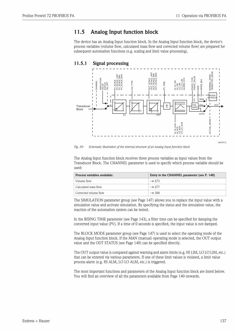
Proline Prowirl 72 PROFIBUS PA 11 Operation via PROFIBUS PA
Endress + Hauser 137
11.5 Analog Input function block
The device has an Analog Input function block. In the Analog Input function block, the device's
process variables (volume flow, calculated mass flow and corrected volume flow) are prepared for
subsequent automation functions (e.g. scaling and limit value processing).
11.5.1 Signal processing
A0003912
Fig. 39: Schematic illustration of the internal structure of an Analog Input function block
The Analog Input function block receives three process variables as input values from the
Transducer Block. The CHANNEL parameter is used to specify which process variable should be
used:
The SIMULATION parameter group (see Page 147) allows you to replace the input value with a
simulation value and activate simulation. By specifying the status and the simulation value, the
reaction of the automation system can be tested.
In the RISING TIME parameter (see Page 143), a filter time can be specified for damping the
converted input value (PV). If a time of 0 seconds is specified, the input value is not damped.
The BLOCK MODE parameter group (see Page 147) is used to select the operating mode of the
Analog Input function block. If the MAN (manual) operating mode is selected, the OUT output
value and the OUT STATUS (see Page 140) can be specified directly.
The OUT output value is compared against warning and alarm limits (e.g. HI LIM, LO LO LIM, etc.)
that can be entered via various parameters. If one of these limit values is violated, a limit value
process alarm (e.g. HI ALM, LO LO ALM, etc.) is triggered.
The most important functions and parameters of the Analog Input function block are listed below.
You will find an overview of all the parameters available from Page 140 onwards.
Process variables available: Entry in the CHANNEL parameter (see P. 148)
Volume flow → 273
Calculated mass flow → 277
Corrected volume flow → 398
1
1
1
0
PV OUT
0
PV
_S
CA
LE
PV
_S
CA
LE
_U
NIT
PV
_S
CA
LE
_M
INP
V_S
CA
LE
_M
AX
OU
T_S
CA
LE
OU
T_S
CA
LE
_U
NIT
OU
T_S
CA
LE
_M
INO
UT
_S
CA
LE
_M
AX
HI_
HI_
LIM
HI_
LIM
LO
_LIM
LO
_LO
_LIM
ALA
RM
_H
YS
HI_
HI_
ALM
HI_
ALM
LO
_A
LM
LO
_LO
_A
LM
TransducerBlock
SIM
ULA
TIO
NV
ALU
ES
TA
TU
SO
N_O
FF
LIN
_T
YP
E
CH
AN
NE
L
NO
RM
AL_M
OD
EP
ER
MIT
TE
D_M
OD
EA
CT
UA
L_M
OD
E
FS
AF
E_T
YP
EF
SA
FE
_V
ALU
E
MO
DE
_B
LK
MA
N
MAN
PV
_T
IME
1
t FAILSAFE
OUT
MODE/STATUS
AUTO
O/S
11 Operation via PROFIBUS PA Proline Prowirl 72 PROFIBUS PA
138 Endress + Hauser
11.5.2 Selecting the operating mode
The operating mode is set by means of the BLOCK MODE parameter group (see Page 147). The
Analog Input function block supports the following operating modes:
• AUTO (automatic mode)
• MAN (manual mode)
• O/S (out of service)
11.5.3 Selecting the units
The system unit for volume flow can be changed using Commuwin II in the Transducer Block
profile and the manufacturer-specific device block.
Changing the unit does not initially have any effect on the measured value transmitted to the
automation system. This ensures that there are no sudden changes in the measured values that
could have an effect on the subsequent control routine.
If the change of unit should affect the measured value, the SET UNIT TO BUS parameter
(manufacturer-specific, see Page 124) can be activated using Commuwin II.
Another way of changing the unit is to use the PV SCALE and OUT SCALE parameters
( → Page 139 "Rescaling the input value").
11.5.4 Status of the OUT output value
The status of the Analog Input function block and the validity of the OUT output value are relayed
to the downstream function blocks by means of the status of the OUT parameter group.
11.5.5 Simulation of input/output
Various parameters of the Analog Input function block allow simulation of the input and output of
the function block:
Simulating the input of the Analog Input function block:
The input value (measured value and status) can be specified by means of the SIMULATION
parameter group (see Page 147). Since the simulation value runs through the entire function block,
all the parameter settings of the block can be checked.
Simulating the output of the Analog Input function block:
Set the operating mode in the MODE BLK parameter group (see Page 147) to MAN and directly
specify the desired output value in the OUT parameter (see Page 140).
Status of the OUT output
value:
Meaning
The output value:
GOOD NON CASCADE → OUT is valid and can be used for further processing.
UNCERTAIN → OUT can only be used for further processing to a limited extent.
BAD → OUT is not valid.
! Note!
The BAD status value occurs when the Analog Input function block is switched to O/S (out-of-service) or in the event of
serious errors (see status code and system/process error messages, → Page 71).
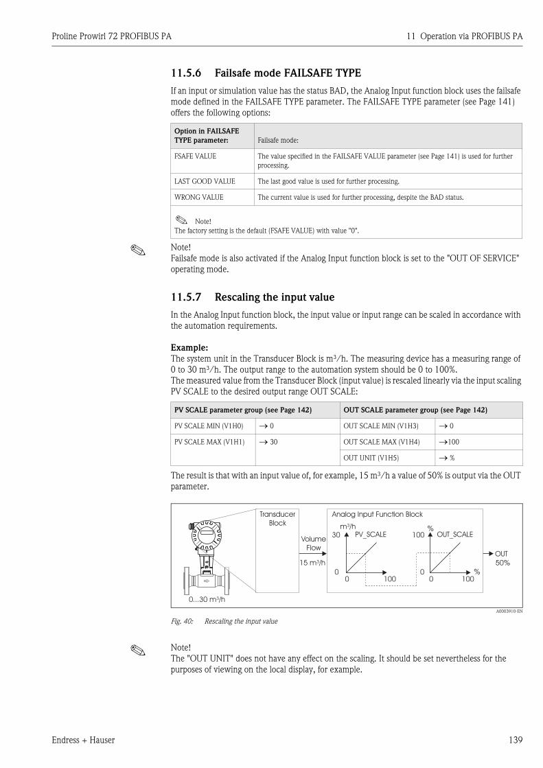
Proline Prowirl 72 PROFIBUS PA 11 Operation via PROFIBUS PA
Endress + Hauser 139
11.5.6 Failsafe mode FAILSAFE TYPE
If an input or simulation value has the status BAD, the Analog Input function block uses the failsafe
mode defined in the FAILSAFE TYPE parameter. The FAILSAFE TYPE parameter (see Page 141)
offers the following options:
! Note!
Failsafe mode is also activated if the Analog Input function block is set to the "OUT OF SERVICE"
operating mode.
11.5.7 Rescaling the input value
In the Analog Input function block, the input value or input range can be scaled in accordance with
the automation requirements.
Example:
The system unit in the Transducer Block is m³/h. The measuring device has a measuring range of
0 to 30 m³/h. The output range to the automation system should be 0 to 100%.
The measured value from the Transducer Block (input value) is rescaled linearly via the input scaling
PV SCALE to the desired output range OUT SCALE:
The result is that with an input value of, for example, 15 m³/h a value of 50% is output via the OUT
parameter.
A0003910-EN
Fig. 40: Rescaling the input value
! Note!
The "OUT UNIT" does not have any effect on the scaling. It should be set nevertheless for the
purposes of viewing on the local display, for example.
Option in FAILSAFE
TYPE parameter: Failsafe mode:
FSAFE VALUE The value specified in the FAILSAFE VALUE parameter (see Page 141) is used for further
processing.
LAST GOOD VALUE The last good value is used for further processing.
WRONG VALUE The current value is used for further processing, despite the BAD status.
! Note!
The factory setting is the default (FSAFE VALUE) with value "0".
PV SCALE parameter group (see Page 142) OUT SCALE parameter group (see Page 142)
PV SCALE MIN (V1H0) → 0 OUT SCALE MIN (V1H3) → 0
PV SCALE MAX (V1H1) → 30 OUT SCALE MAX (V1H4) →100
OUT UNIT (V1H5) → %
Esc
E- +
OUT
50%
TransducerBlock
PV_SCALE OUT_SCALE
0 00 0
30 100
100
%
Analog Input Function Block
%100
VolumeFlow
m³/h
15 m³/h
0...30 m³/h
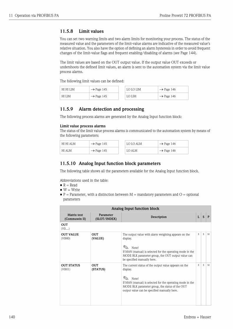
11 Operation via PROFIBUS PA Proline Prowirl 72 PROFIBUS PA
140 Endress + Hauser
11.5.8 Limit values
You can set two warning limits and two alarm limits for monitoring your process. The status of the
measured value and the parameters of the limit-value alarms are indicative of the measured value's
relative situation. You also have the option of defining an alarm hysteresis in order to avoid frequent
changes of the limit-value flags and frequent enabling/disabling of alarms (see Page 144).
The limit values are based on the OUT output value. If the output value OUT exceeds or
undershoots the defined limit values, an alarm is sent to the automation system via the limit value
process alarms.
The following limit values can be defined:
11.5.9 Alarm detection and processing
The following process alarms are generated by the Analog Input function block:
Limit value process alarms
The status of the limit value process alarms is communicated to the automation system by means of
the following parameters:
11.5.10 Analog Input function block parameters
The following table shows all the parameters available for the Analog Input function block.
Abbreviations used in the table:
• R = Read
• W = Write
• P = Parameter, with a distinction between M = mandatory parameters and O = optional
parameters
HI HI LIM → Page 145 LO LO LIM → Page 146
HI LIM → Page 145 LO LIM → Page 146
HI HI ALM → Page 145 LO LO ALM → Page 146
HI ALM → Page 145 LO ALM → Page 146
Analog Input function block
Matrix text
(Commuwin II)
Parameter
(SLOT/INDEX)Description L S P
OUT
(V0…)
OUT VALUE
(V0H0)
OUT
(VALUE)
The output value with alarm weighting appears on the
display.
! Note!
If MAN (manual) is selected for the operating mode in the
MODE BLK parameter group, the OUT output value can
be specified manually here.
X X M
OUT STATUS
(V0H1)
OUT
(STATUS)
The current status of the output value appears on the
display.
! Note!
If MAN (manual) is selected for the operating mode in the
MODE BLK parameter group, the status of the OUT
output value can be specified manually here.
X X M
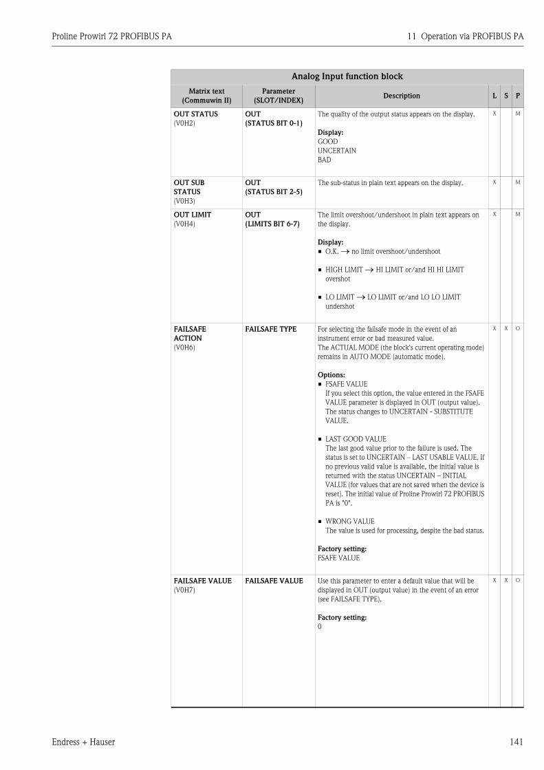
Proline Prowirl 72 PROFIBUS PA 11 Operation via PROFIBUS PA
Endress + Hauser 141
OUT STATUS
(V0H2)
OUT
(STATUS BIT 0-1)
The quality of the output status appears on the display.
Display:
GOOD
UNCERTAIN
BAD
X M
OUT SUB
STATUS
(V0H3)
OUT
(STATUS BIT 2-5)
The sub-status in plain text appears on the display. X M
OUT LIMIT
(V0H4)
OUT
(LIMITS BIT 6-7)
The limit overshoot/undershoot in plain text appears on
the display.
Display:
• O.K. → no limit overshoot/undershoot
• HIGH LIMIT → HI LIMIT or/and HI HI LIMIT
overshot
• LO LIMIT → LO LIMIT or/and LO LO LIMIT
undershot
X M
FAILSAFE
ACTION
(V0H6)
FAILSAFE TYPE For selecting the failsafe mode in the event of an
instrument error or bad measured value.
The ACTUAL MODE (the block's current operating mode)
remains in AUTO MODE (automatic mode).
Options:
• FSAFE VALUE
If you select this option, the value entered in the FSAFE
VALUE parameter is displayed in OUT (output value).
The status changes to UNCERTAIN - SUBSTITUTE
VALUE.
• LAST GOOD VALUE
The last good value prior to the failure is used. The
status is set to UNCERTAIN – LAST USABLE VALUE. If
no previous valid value is available, the initial value is
returned with the status UNCERTAIN – INITIAL
VALUE (for values that are not saved when the device is
reset). The initial value of Proline Prowirl 72 PROFIBUS
PA is "0".
• WRONG VALUE
The value is used for processing, despite the bad status.
Factory setting:
FSAFE VALUE
X X O
FAILSAFE VALUE
(V0H7)
FAILSAFE VALUE Use this parameter to enter a default value that will be
displayed in OUT (output value) in the event of an error
(see FAILSAFE TYPE).
Factory setting:
0
X X O
Analog Input function block
Matrix text
(Commuwin II)
Parameter
(SLOT/INDEX)Description L S P
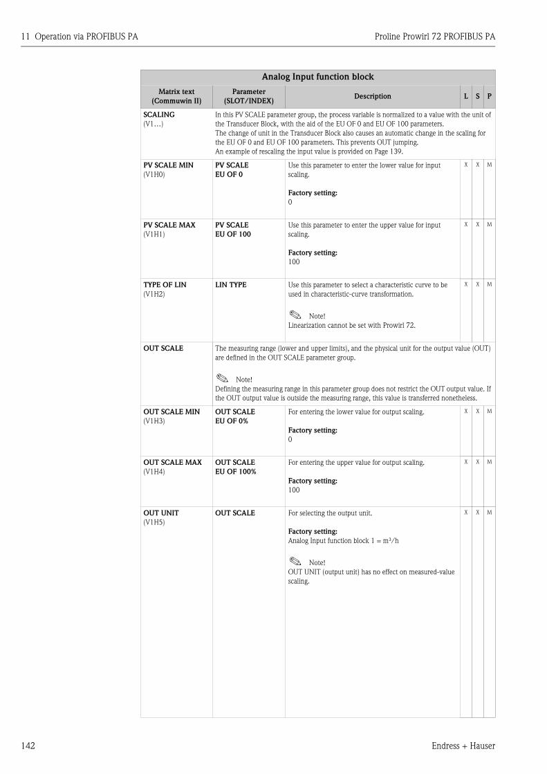
11 Operation via PROFIBUS PA Proline Prowirl 72 PROFIBUS PA
142 Endress + Hauser
SCALING
(V1…)
In this PV SCALE parameter group, the process variable is normalized to a value with the unit of
the Transducer Block, with the aid of the EU OF 0 and EU OF 100 parameters.
The change of unit in the Transducer Block also causes an automatic change in the scaling for
the EU OF 0 and EU OF 100 parameters. This prevents OUT jumping.
An example of rescaling the input value is provided on Page 139.
PV SCALE MIN
(V1H0)
PV SCALE
EU OF 0
Use this parameter to enter the lower value for input
scaling.
Factory setting:
0
X X M
PV SCALE MAX
(V1H1)
PV SCALE
EU OF 100
Use this parameter to enter the upper value for input
scaling.
Factory setting:
100
X X M
TYPE OF LIN
(V1H2)
LIN TYPE Use this parameter to select a characteristic curve to be
used in characteristic-curve transformation.
! Note!
Linearization cannot be set with Prowirl 72.
X X M
OUT SCALE The measuring range (lower and upper limits), and the physical unit for the output value (OUT)
are defined in the OUT SCALE parameter group.
! Note!
Defining the measuring range in this parameter group does not restrict the OUT output value. If
the OUT output value is outside the measuring range, this value is transferred nonetheless.
OUT SCALE MIN
(V1H3)
OUT SCALE
EU OF 0%
For entering the lower value for output scaling.
Factory setting:
0
X X M
OUT SCALE MAX
(V1H4)
OUT SCALE
EU OF 100%
For entering the upper value for output scaling.
Factory setting:
100
X X M
OUT UNIT
(V1H5)
OUT SCALE For selecting the output unit.
Factory setting:
Analog Input function block 1 = m³/h
! Note!
OUT UNIT (output unit) has no effect on measured-value
scaling.
X X M
Analog Input function block
Matrix text
(Commuwin II)
Parameter
(SLOT/INDEX)Description L S P
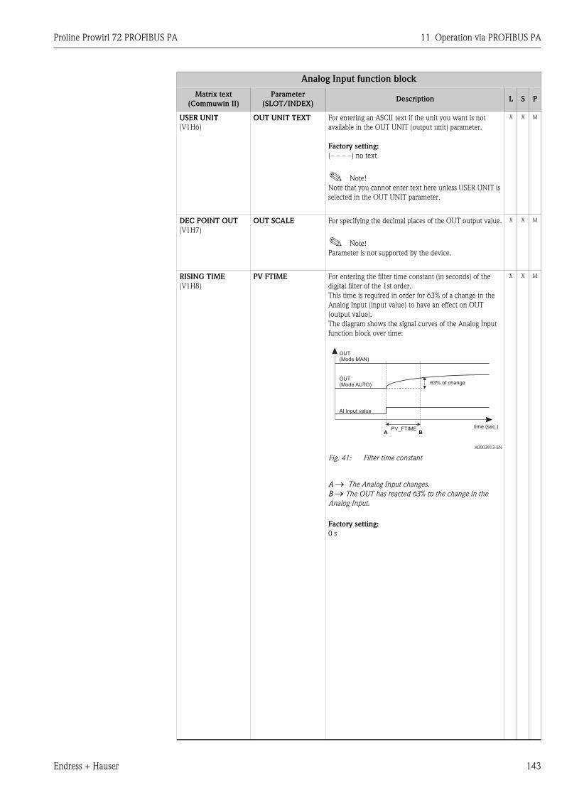
Proline Prowirl 72 PROFIBUS PA 11 Operation via PROFIBUS PA
Endress + Hauser 143
USER UNIT
(V1H6)
OUT UNIT TEXT For entering an ASCII text if the unit you want is not
available in the OUT UNIT (output unit) parameter.
Factory setting:
(– – – –) no text
! Note!
Note that you cannot enter text here unless USER UNIT is
selected in the OUT UNIT parameter.
X X M
DEC POINT OUT
(V1H7)
OUT SCALE For specifying the decimal places of the OUT output value.
! Note!
Parameter is not supported by the device.
X X M
RISING TIME
(V1H8)
PV FTIME For entering the filter time constant (in seconds) of the
digital filter of the 1st order.
This time is required in order for 63% of a change in the
Analog Input (input value) to have an effect on OUT
(output value).
The diagram shows the signal curves of the Analog Input
function block over time:
A0003913-EN
Fig. 41: Filter time constant
A → The Analog Input changes.
B → The OUT has reacted 63% to the change in the
Analog Input.
Factory setting:
0 s
X X M
Analog Input function block
Matrix text
(Commuwin II)
Parameter
(SLOT/INDEX)Description L S P
A B
OUT(Mode MAN)
OUT(Mode AUTO)
AI Input value
PV_FTIME
63% of change
time (sec.)
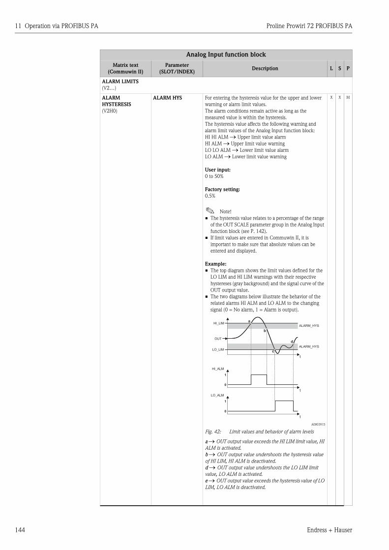
11 Operation via PROFIBUS PA Proline Prowirl 72 PROFIBUS PA
144 Endress + Hauser
ALARM LIMITS
(V2…)
ALARM
HYSTERESIS
(V2H0)
ALARM HYS For entering the hysteresis value for the upper and lower
warning or alarm limit values.
The alarm conditions remain active as long as the
measured value is within the hysteresis.
The hysteresis value affects the following warning and
alarm limit values of the Analog Input function block:
HI HI ALM → Upper limit value alarm
HI ALM → Upper limit value warning
LO LO ALM → Lower limit value alarm
LO ALM → Lower limit value warning
User input:
0 to 50%
Factory setting:
0.5%
! Note!
• The hysteresis value relates to a percentage of the range
of the OUT SCALE parameter group in the Analog Input
function block (see P. 142).
• If limit values are entered in Commuwin II, it is
important to make sure that absolute values can be
entered and displayed.
Example:
• The top diagram shows the limit values defined for the
LO LIM and HI LIM warnings with their respective
hystereses (gray background) and the signal curve of the
OUT output value.
• The two diagrams below illustrate the behavior of the
related alarms HI ALM and LO ALM to the changing
signal (0 = No alarm, 1 = Alarm is output).
A0003915
Fig. 42: Limit values and behavior of alarm levels
a → OUT output value exceeds the HI LIM limit value, HI
ALM is activated.
b → OUT output value undershoots the hysteresis value
of HI LIM, HI ALM is deactivated.
d → OUT output value undershoots the LO LIM limit
value, LO ALM is activated.
e → OUT output value exceeds the hysteresis value of LO
LIM, LO ALM is deactivated.
X X M
Analog Input function block
Matrix text
(Commuwin II)
Parameter
(SLOT/INDEX)Description L S P
ALARM_HYS
ALARM_HYS
t
t
t
HI_ALM
LO_ALM
1
a
b
c
d
1
0
0
HI_LIM
LO_LIM
OUT

Proline Prowirl 72 PROFIBUS PA 11 Operation via PROFIBUS PA
Endress + Hauser 145
HI HI ALARM
(V3…)
HI HI LIM
(V3H0)
HI HI LIM For entering the alarm limit value for the upper alarm (HI
HI ALM). If the OUT output value exceeds this limit value,
the alarm status parameter HI HI ALM is output.
User input:
Range and unit of OUT SCALE
Factory setting:
3402823466 x 1038
X X M
VALUE
(V3H1)
HI HI ALM
(VALUE)
Alarm status parameter for the upper alarm limit.
Content includes the value that violated the limit.
X O
ALARM STATE
(V3H2)
HI HI ALM
(ALARM STATE)
The current HI HI ALARM state appears on the display. X O
SWITCH-ON POINT
(V3H3)
HI HI ALM
(SWITCH-ON
POINT)
The switch-on point as a function of the hysteresis value
appears on the display.
X O
SWITCH-OFF
POINT
(V3H4)
HI HI ALM
(SWITCH-OFF
POINT)
The switch-off point as a function of the hysteresis value
appears on the display.
X O
HI ALARM
(V4…)
HI LIM
(V4H0)
HI LIM For entering the alarm limit value for the upper warning
(HI ALM). If the OUT output value exceeds this limit
value, the alarm status parameter HI ALM is output.
User input:
Range and unit of OUT SCALE
Factory setting:
3402823466 x 1038
X X M
VALUE
(V4H1)
HI ALM
(VALUE)
Alarm status parameter for the upper warning limit.
Content includes the value that violated the limit.
X O
ALARM STATE
(V4H2)
HI ALM
(ALARM STATE)
The current HI ALARM state appears on the display. X O
SWITCH-ON POINT
(V4H3)
HI ALM
(SWITCH-ON
POINT)
The switch-on point as a function of the hysteresis value
appears on the display.
X O
SWITCH-OFF
POINT
(V4H4)
HI ALM
(SWITCH-OFF
POINT)
The switch-off point as a function of the hysteresis value
appears on the display.
X O
Analog Input function block
Matrix text
(Commuwin II)
Parameter
(SLOT/INDEX)Description L S P
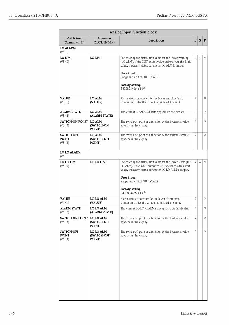
11 Operation via PROFIBUS PA Proline Prowirl 72 PROFIBUS PA
146 Endress + Hauser
LO ALARM
(V5…)
LO LIM
(V5H0)
LO LIM For entering the alarm limit value for the lower warning
(LO ALM). If the OUT output value undershoots this limit
value, the alarm status parameter LO ALM is output.
User input:
Range and unit of OUT SCALE
Factory setting:
3402823466 x 1038
X X M
VALUE
(V5H1)
LO ALM
(VALUE)
Alarm status parameter for the lower warning limit.
Content includes the value that violated the limit.
X O
ALARM STATE
(V5H2)
LO ALM
(ALARM STATE)
The current LO ALARM state appears on the display. X O
SWITCH-ON POINT
(V5H3)
LO ALM
(SWITCH-ON
POINT)
The switch-on point as a function of the hysteresis value
appears on the display.
X O
SWITCH-OFF
POINT
(V5H4)
LO ALM
(SWITCH-OFF
POINT)
The switch-off point as a function of the hysteresis value
appears on the display.
X O
LO LO ALARM
(V6…)
LO LO LIM
(V6H0)
LO LO LIM For entering the alarm limit value for the lower alarm (LO
LO ALM). If the OUT output value undershoots this limit
value, the alarm status parameter LO LO ALM is output.
User input:
Range and unit of OUT SCALE
Factory setting:
3402823466 x 1038
X X M
VALUE
(V6H1)
LO LO ALM
(VALUE)
Alarm status parameter for the lower alarm limit.
Content includes the value that violated the limit.
X O
ALARM STATE
(V6H2)
LO LO ALM
(ALARM STATE)
The current LO LO ALARM state appears on the display. X O
SWITCH-ON POINT
(V6H3)
LO LO ALM
(SWITCH-ON
POINT)
The switch-on point as a function of the hysteresis value
appears on the display.
X O
SWITCH-OFF
POINT
(V6H4)
LO LO ALM
(SWITCH-OFF
POINT)
The switch-off point as a function of the hysteresis value
appears on the display.
X O
Analog Input function block
Matrix text
(Commuwin II)
Parameter
(SLOT/INDEX)Description L S P
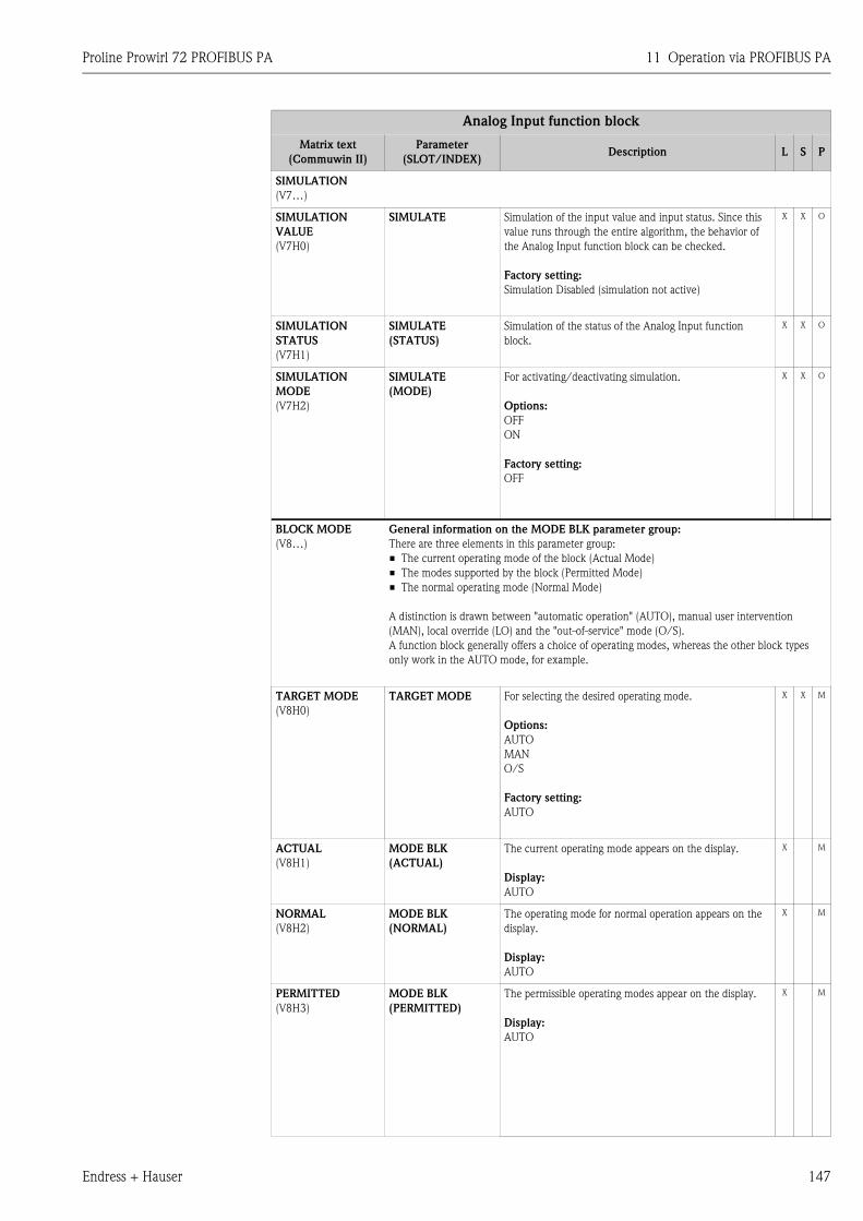
Proline Prowirl 72 PROFIBUS PA 11 Operation via PROFIBUS PA
Endress + Hauser 147
SIMULATION
(V7…)
SIMULATION
VALUE
(V7H0)
SIMULATE Simulation of the input value and input status. Since this
value runs through the entire algorithm, the behavior of
the Analog Input function block can be checked.
Factory setting:
Simulation Disabled (simulation not active)
X X O
SIMULATION
STATUS
(V7H1)
SIMULATE
(STATUS)
Simulation of the status of the Analog Input function
block.
X X O
SIMULATION
MODE
(V7H2)
SIMULATE
(MODE)
For activating/deactivating simulation.
Options:
OFF
ON
Factory setting:
OFF
X X O
BLOCK MODE
(V8…)
General information on the MODE BLK parameter group:
There are three elements in this parameter group:
• The current operating mode of the block (Actual Mode)
• The modes supported by the block (Permitted Mode)
• The normal operating mode (Normal Mode)
A distinction is drawn between "automatic operation" (AUTO), manual user intervention
(MAN), local override (LO) and the "out-of-service" mode (O/S).
A function block generally offers a choice of operating modes, whereas the other block types
only work in the AUTO mode, for example.
TARGET MODE
(V8H0)
TARGET MODE For selecting the desired operating mode.
Options:
AUTO
MAN
O/S
Factory setting:
AUTO
X X M
ACTUAL
(V8H1)
MODE BLK
(ACTUAL)
The current operating mode appears on the display.
Display:
AUTO
X M
NORMAL
(V8H2)
MODE BLK
(NORMAL)
The operating mode for normal operation appears on the
display.
Display:
AUTO
X M
PERMITTED
(V8H3)
MODE BLK
(PERMITTED)
The permissible operating modes appear on the display.
Display:
AUTO
X M
Analog Input function block
Matrix text
(Commuwin II)
Parameter
(SLOT/INDEX)Description L S P
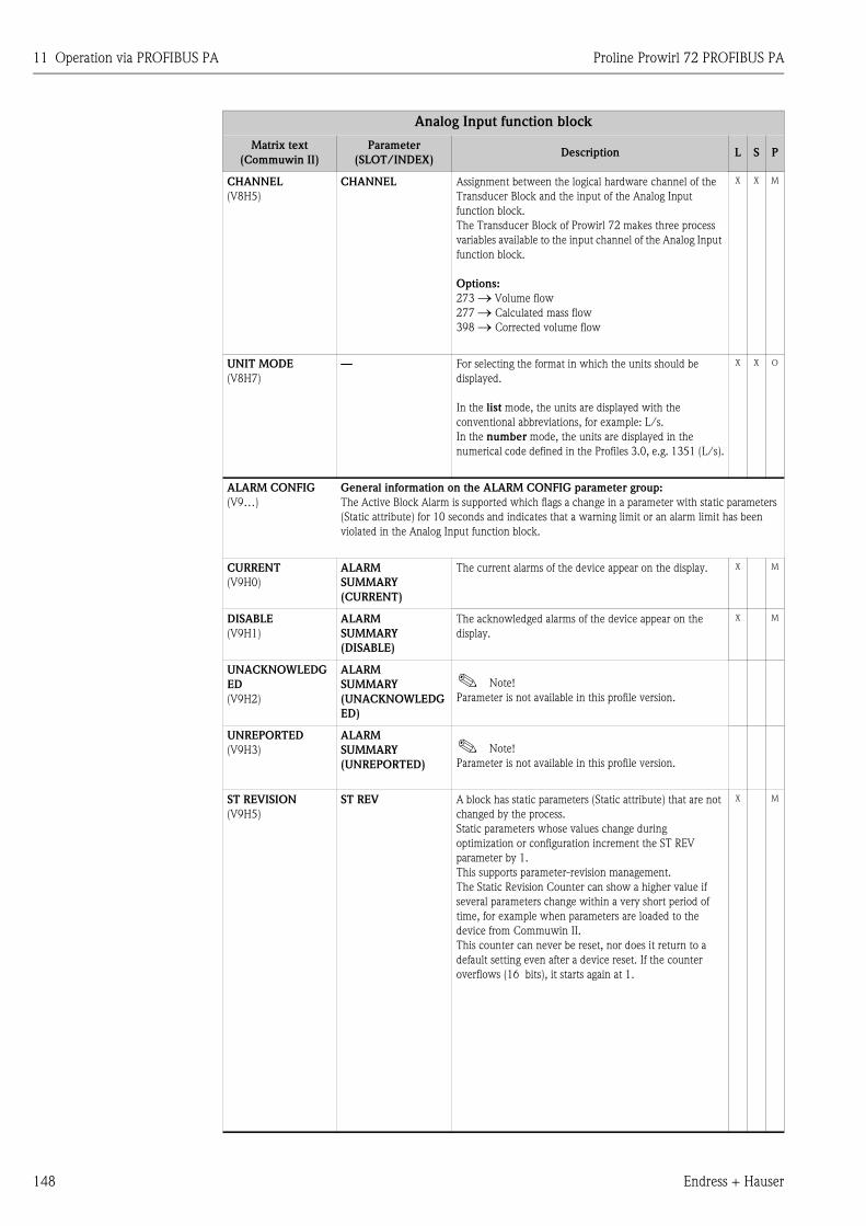
11 Operation via PROFIBUS PA Proline Prowirl 72 PROFIBUS PA
148 Endress + Hauser
CHANNEL
(V8H5)
CHANNEL Assignment between the logical hardware channel of the
Transducer Block and the input of the Analog Input
function block.
The Transducer Block of Prowirl 72 makes three process
variables available to the input channel of the Analog Input
function block.
Options:
273 → Volume flow
277 → Calculated mass flow
398 → Corrected volume flow
X X M
UNIT MODE
(V8H7)
— For selecting the format in which the units should be
displayed.
In the list mode, the units are displayed with the
conventional abbreviations, for example: L/s.
In the number mode, the units are displayed in the
numerical code defined in the Profiles 3.0, e.g. 1351 (L/s).
X X O
ALARM CONFIG
(V9…)
General information on the ALARM CONFIG parameter group:
The Active Block Alarm is supported which flags a change in a parameter with static parameters
(Static attribute) for 10 seconds and indicates that a warning limit or an alarm limit has been
violated in the Analog Input function block.
CURRENT
(V9H0)
ALARM
SUMMARY
(CURRENT)
The current alarms of the device appear on the display. X M
DISABLE
(V9H1)
ALARM
SUMMARY
(DISABLE)
The acknowledged alarms of the device appear on the
display.
X M
UNACKNOWLEDG
ED
(V9H2)
ALARM
SUMMARY
(UNACKNOWLEDG
ED)
! Note!
Parameter is not available in this profile version.
UNREPORTED
(V9H3)
ALARM
SUMMARY
(UNREPORTED)
! Note!
Parameter is not available in this profile version.
ST REVISION
(V9H5)
ST REV A block has static parameters (Static attribute) that are not
changed by the process.
Static parameters whose values change during
optimization or configuration increment the ST REV
parameter by 1.
This supports parameter-revision management.
The Static Revision Counter can show a higher value if
several parameters change within a very short period of
time, for example when parameters are loaded to the
device from Commuwin II.
This counter can never be reset, nor does it return to a
default setting even after a device reset. If the counter
overflows (16 bits), it starts again at 1.
X M
Analog Input function block
Matrix text
(Commuwin II)
Parameter
(SLOT/INDEX)Description L S P
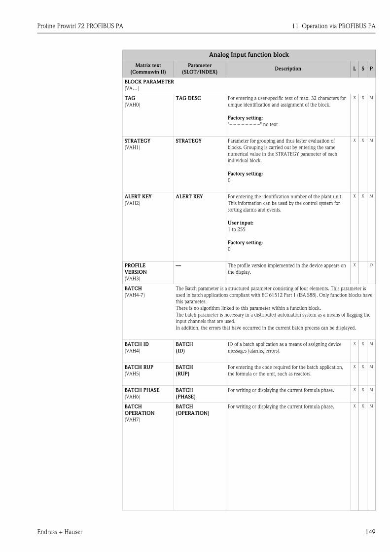
Proline Prowirl 72 PROFIBUS PA 11 Operation via PROFIBUS PA
Endress + Hauser 149
BLOCK PARAMETER
(VA…)
TAG
(VAH0)
TAG DESC For entering a user-specific text of max. 32 characters for
unique identification and assignment of the block.
Factory setting:
"– – – – – – – –" no text
X X M
STRATEGY
(VAH1)
STRATEGY Parameter for grouping and thus faster evaluation of
blocks. Grouping is carried out by entering the same
numerical value in the STRATEGY parameter of each
individual block.
Factory setting:
0
X X M
ALERT KEY
(VAH2)
ALERT KEY For entering the identification number of the plant unit.
This information can be used by the control system for
sorting alarms and events.
User input:
1 to 255
Factory setting:
0
X X M
PROFILE
VERSION
(VAH3)
— The profile version implemented in the device appears on
the display.
X O
BATCH
(VAH4-7)
The Batch parameter is a structured parameter consisting of four elements. This parameter is
used in batch applications compliant with EC 61512 Part 1 (ISA S88). Only function blocks have
this parameter.
There is no algorithm linked to this parameter within a function block.
The batch parameter is necessary in a distributed automation system as a means of flagging the
input channels that are used.
In addition, the errors that have occurred in the current batch process can be displayed.
BATCH ID
(VAH4)
BATCH
(ID)
ID of a batch application as a means of assigning device
messages (alarms, errors).
X X M
BATCH RUP
(VAH5)
BATCH
(RUP)
For entering the code required for the batch application,
the formula or the unit, such as reactors.
X X M
BATCH PHASE
(VAH6)
BATCH
(PHASE)
For writing or displaying the current formula phase. X X M
BATCH
OPERATION
(VAH7)
BATCH
(OPERATION)
For writing or displaying the current formula phase. X X M
Analog Input function block
Matrix text
(Commuwin II)
Parameter
(SLOT/INDEX)Description L S P
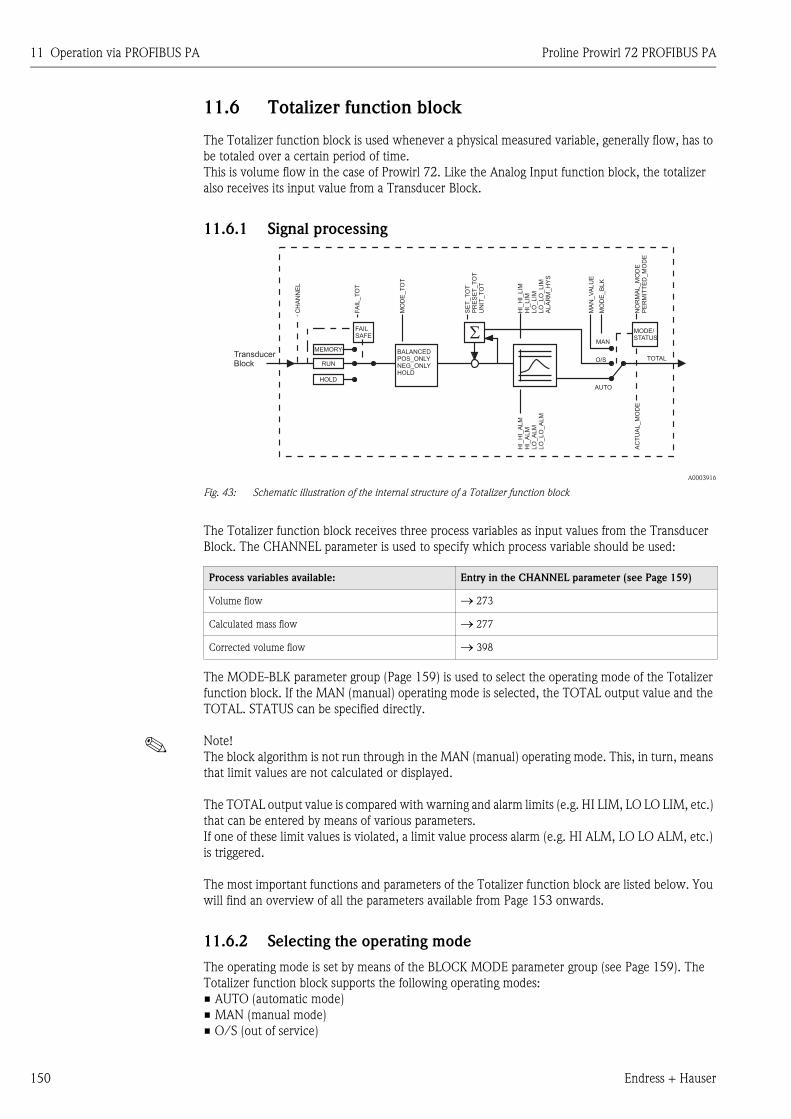
11 Operation via PROFIBUS PA Proline Prowirl 72 PROFIBUS PA
150 Endress + Hauser
11.6 Totalizer function block
The Totalizer function block is used whenever a physical measured variable, generally flow, has to
be totaled over a certain period of time.
This is volume flow in the case of Prowirl 72. Like the Analog Input function block, the totalizer
also receives its input value from a Transducer Block.
11.6.1 Signal processing
A0003916
Fig. 43: Schematic illustration of the internal structure of a Totalizer function block
The Totalizer function block receives three process variables as input values from the Transducer
Block. The CHANNEL parameter is used to specify which process variable should be used:
The MODE-BLK parameter group (Page 159) is used to select the operating mode of the Totalizer
function block. If the MAN (manual) operating mode is selected, the TOTAL output value and the
TOTAL. STATUS can be specified directly.
! Note!
The block algorithm is not run through in the MAN (manual) operating mode. This, in turn, means
that limit values are not calculated or displayed.
The TOTAL output value is compared with warning and alarm limits (e.g. HI LIM, LO LO LIM, etc.)
that can be entered by means of various parameters.
If one of these limit values is violated, a limit value process alarm (e.g. HI ALM, LO LO ALM, etc.)
is triggered.
The most important functions and parameters of the Totalizer function block are listed below. You
will find an overview of all the parameters available from Page 153 onwards.
11.6.2 Selecting the operating mode
The operating mode is set by means of the BLOCK MODE parameter group (see Page 159). The
Totalizer function block supports the following operating modes:
• AUTO (automatic mode)
• MAN (manual mode)
• O/S (out of service)
Process variables available: Entry in the CHANNEL parameter (see Page 159)
Volume flow → 273
Calculated mass flow → 277
Corrected volume flow → 398
SE
T_T
OT
PR
ES
ET
_T
OT
UN
IT_T
OT
HI_
HI_
LIM
HI_
LIM
LO
_LIM
LO
_LO
_LIM
ALA
RM
_H
YS
HI_
HI_
ALM
HI_
ALM
LO
_A
LM
LO
_LO
_A
LM
MO
DE
_T
OT
CH
AN
NE
L
NO
RM
AL_M
OD
EP
ER
MIT
TE
D_M
OD
EA
CT
UA
L_M
OD
E
FA
IL_T
OT
MO
DE
_B
LK
MAN
MA
N_V
ALU
E
SFAILSAFE
MEMORY
HOLD
RUNTOTAL
MODE/STATUS
AUTO
BALANCEDPOS_ONLYNEG_ONLYHOLD
O/STransducerBlock
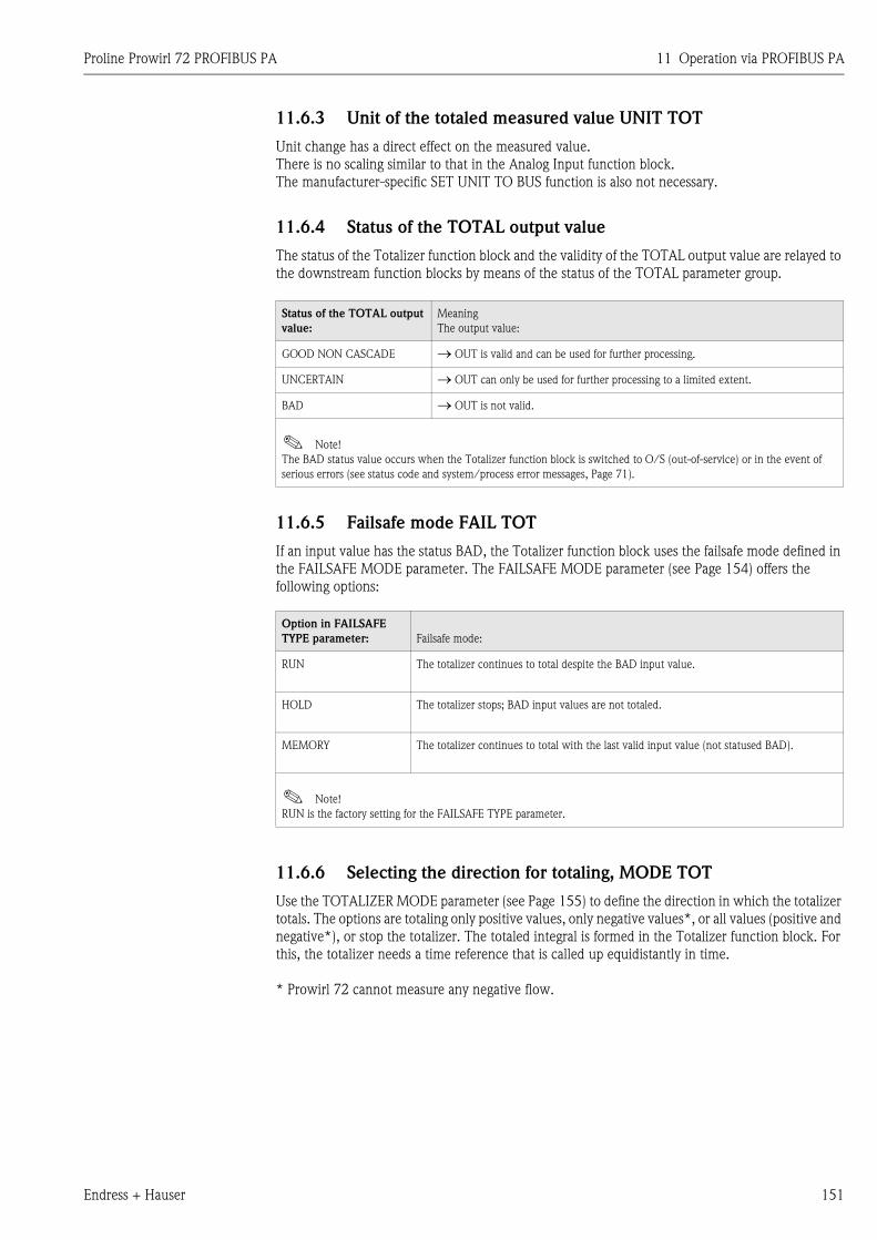
Proline Prowirl 72 PROFIBUS PA 11 Operation via PROFIBUS PA
Endress + Hauser 151
11.6.3 Unit of the totaled measured value UNIT TOT
Unit change has a direct effect on the measured value.
There is no scaling similar to that in the Analog Input function block.
The manufacturer-specific SET UNIT TO BUS function is also not necessary.
11.6.4 Status of the TOTAL output value
The status of the Totalizer function block and the validity of the TOTAL output value are relayed to
the downstream function blocks by means of the status of the TOTAL parameter group.
11.6.5 Failsafe mode FAIL TOT
If an input value has the status BAD, the Totalizer function block uses the failsafe mode defined in
the FAILSAFE MODE parameter. The FAILSAFE MODE parameter (see Page 154) offers the
following options:
11.6.6 Selecting the direction for totaling, MODE TOT
Use the TOTALIZER MODE parameter (see Page 155) to define the direction in which the totalizer
totals. The options are totaling only positive values, only negative values*, or all values (positive and
negative*), or stop the totalizer. The totaled integral is formed in the Totalizer function block. For
this, the totalizer needs a time reference that is called up equidistantly in time.
* Prowirl 72 cannot measure any negative flow.
Status of the TOTAL output
value:
Meaning
The output value:
GOOD NON CASCADE → OUT is valid and can be used for further processing.
UNCERTAIN → OUT can only be used for further processing to a limited extent.
BAD → OUT is not valid.
! Note!
The BAD status value occurs when the Totalizer function block is switched to O/S (out-of-service) or in the event of
serious errors (see status code and system/process error messages, Page 71).
Option in FAILSAFE
TYPE parameter: Failsafe mode:
RUN The totalizer continues to total despite the BAD input value.
HOLD The totalizer stops; BAD input values are not totaled.
MEMORY The totalizer continues to total with the last valid input value (not statused BAD).
! Note!
RUN is the factory setting for the FAILSAFE TYPE parameter.
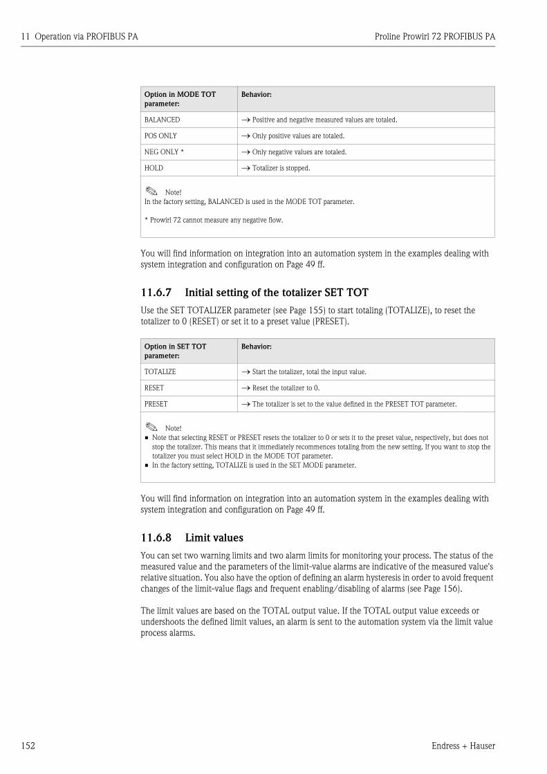
11 Operation via PROFIBUS PA Proline Prowirl 72 PROFIBUS PA
152 Endress + Hauser
You will find information on integration into an automation system in the examples dealing with
system integration and configuration on Page 49 ff.
11.6.7 Initial setting of the totalizer SET TOT
Use the SET TOTALIZER parameter (see Page 155) to start totaling (TOTALIZE), to reset the
totalizer to 0 (RESET) or set it to a preset value (PRESET).
You will find information on integration into an automation system in the examples dealing with
system integration and configuration on Page 49 ff.
11.6.8 Limit values
You can set two warning limits and two alarm limits for monitoring your process. The status of the
measured value and the parameters of the limit-value alarms are indicative of the measured value's
relative situation. You also have the option of defining an alarm hysteresis in order to avoid frequent
changes of the limit-value flags and frequent enabling/disabling of alarms (see Page 156).
The limit values are based on the TOTAL output value. If the TOTAL output value exceeds or
undershoots the defined limit values, an alarm is sent to the automation system via the limit value
process alarms.
Option in MODE TOT
parameter:
Behavior:
BALANCED → Positive and negative measured values are totaled.
POS ONLY → Only positive values are totaled.
NEG ONLY * → Only negative values are totaled.
HOLD → Totalizer is stopped.
! Note!
In the factory setting, BALANCED is used in the MODE TOT parameter.
* Prowirl 72 cannot measure any negative flow.
Option in SET TOT
parameter:
Behavior:
TOTALIZE → Start the totalizer, total the input value.
RESET → Reset the totalizer to 0.
PRESET → The totalizer is set to the value defined in the PRESET TOT parameter.
! Note!
• Note that selecting RESET or PRESET resets the totalizer to 0 or sets it to the preset value, respectively, but does not
stop the totalizer. This means that it immediately recommences totaling from the new setting. If you want to stop the
totalizer you must select HOLD in the MODE TOT parameter.
• In the factory setting, TOTALIZE is used in the SET MODE parameter.
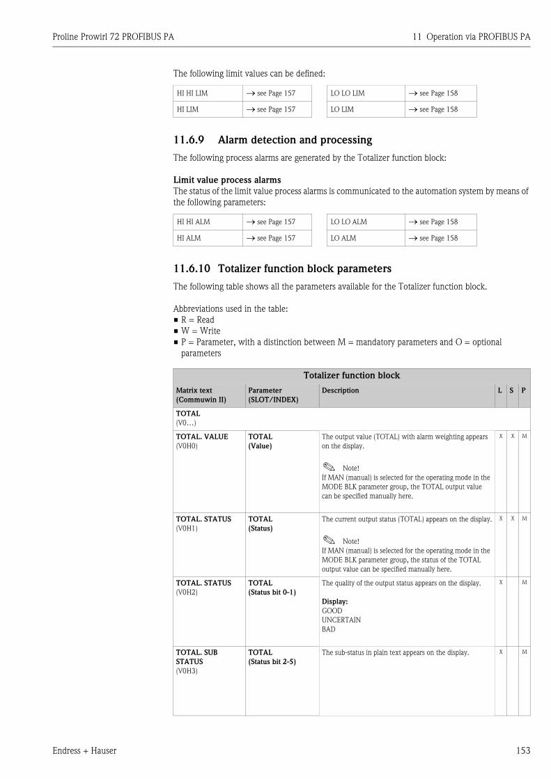
Proline Prowirl 72 PROFIBUS PA 11 Operation via PROFIBUS PA
Endress + Hauser 153
The following limit values can be defined:
11.6.9 Alarm detection and processing
The following process alarms are generated by the Totalizer function block:
Limit value process alarms
The status of the limit value process alarms is communicated to the automation system by means of
the following parameters:
11.6.10 Totalizer function block parameters
The following table shows all the parameters available for the Totalizer function block.
Abbreviations used in the table:
• R = Read
• W = Write
• P = Parameter, with a distinction between M = mandatory parameters and O = optional
parameters
HI HI LIM → see Page 157 LO LO LIM → see Page 158
HI LIM → see Page 157 LO LIM → see Page 158
HI HI ALM → see Page 157 LO LO ALM → see Page 158
HI ALM → see Page 157 LO ALM → see Page 158
Totalizer function block
Matrix text
(Commuwin II)
Parameter
(SLOT/INDEX)
Description L S P
TOTAL
(V0…)
TOTAL. VALUE
(V0H0)
TOTAL
(Value)
The output value (TOTAL) with alarm weighting appears
on the display.
! Note!
If MAN (manual) is selected for the operating mode in the
MODE BLK parameter group, the TOTAL output value
can be specified manually here.
X X M
TOTAL. STATUS
(V0H1)
TOTAL
(Status)
The current output status (TOTAL) appears on the display.
! Note!
If MAN (manual) is selected for the operating mode in the
MODE BLK parameter group, the status of the TOTAL
output value can be specified manually here.
X X M
TOTAL. STATUS
(V0H2)
TOTAL
(Status bit 0-1)
The quality of the output status appears on the display.
Display:
GOOD
UNCERTAIN
BAD
X M
TOTAL. SUB
STATUS
(V0H3)
TOTAL
(Status bit 2-5)
The sub-status in plain text appears on the display. X M
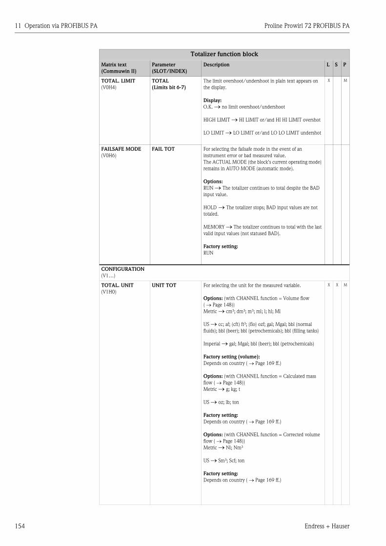
11 Operation via PROFIBUS PA Proline Prowirl 72 PROFIBUS PA
154 Endress + Hauser
TOTAL. LIMIT
(V0H4)
TOTAL
(Limits bit 6-7)
The limit overshoot/undershoot in plain text appears on
the display.
Display:
O.K. → no limit overshoot/undershoot
HIGH LIMIT → HI LIMIT or/and HI HI LIMIT overshot
LO LIMIT → LO LIMIT or/and LO LO LIMIT undershot
X M
FAILSAFE MODE
(V0H6)
FAIL TOT For selecting the failsafe mode in the event of an
instrument error or bad measured value.
The ACTUAL MODE (the block's current operating mode)
remains in AUTO MODE (automatic mode).
Options:
RUN → The totalizer continues to total despite the BAD
input value.
HOLD → The totalizer stops; BAD input values are not
totaled.
MEMORY → The totalizer continues to total with the last
valid input values (not statused BAD).
Factory setting:
RUN
CONFIGURATION
(V1…)
TOTAL. UNIT
(V1H0)
UNIT TOT For selecting the unit for the measured variable.
Options: (with CHANNEL function = Volume flow
( → Page 148))
Metric → cm³; dm³; m³; ml; l; hl; Ml
US → cc; af; (cft) ft³; (flo) ozf; gal; Mgal; bbl (normal
fluids); bbl (beer); bbl (petrochemicals); bbl (filling tanks)
Imperial → gal; Mgal; bbl (beer); bbl (petrochemicals)
Factory setting (volume):
Depends on country ( → Page 169 ff.)
Options: (with CHANNEL function = Calculated mass
flow ( → Page 148))
Metric → g; kg; t
US → oz; lb; ton
Factory setting:
Depends on country ( → Page 169 ff.)
Options: (with CHANNEL function = Corrected volume
flow ( → Page 148))
Metric → Nl; Nm³
US → Sm³; Scf; ton
Factory setting:
Depends on country ( → Page 169 ff.)
X X M
Totalizer function block
Matrix text
(Commuwin II)
Parameter
(SLOT/INDEX)
Description L S P
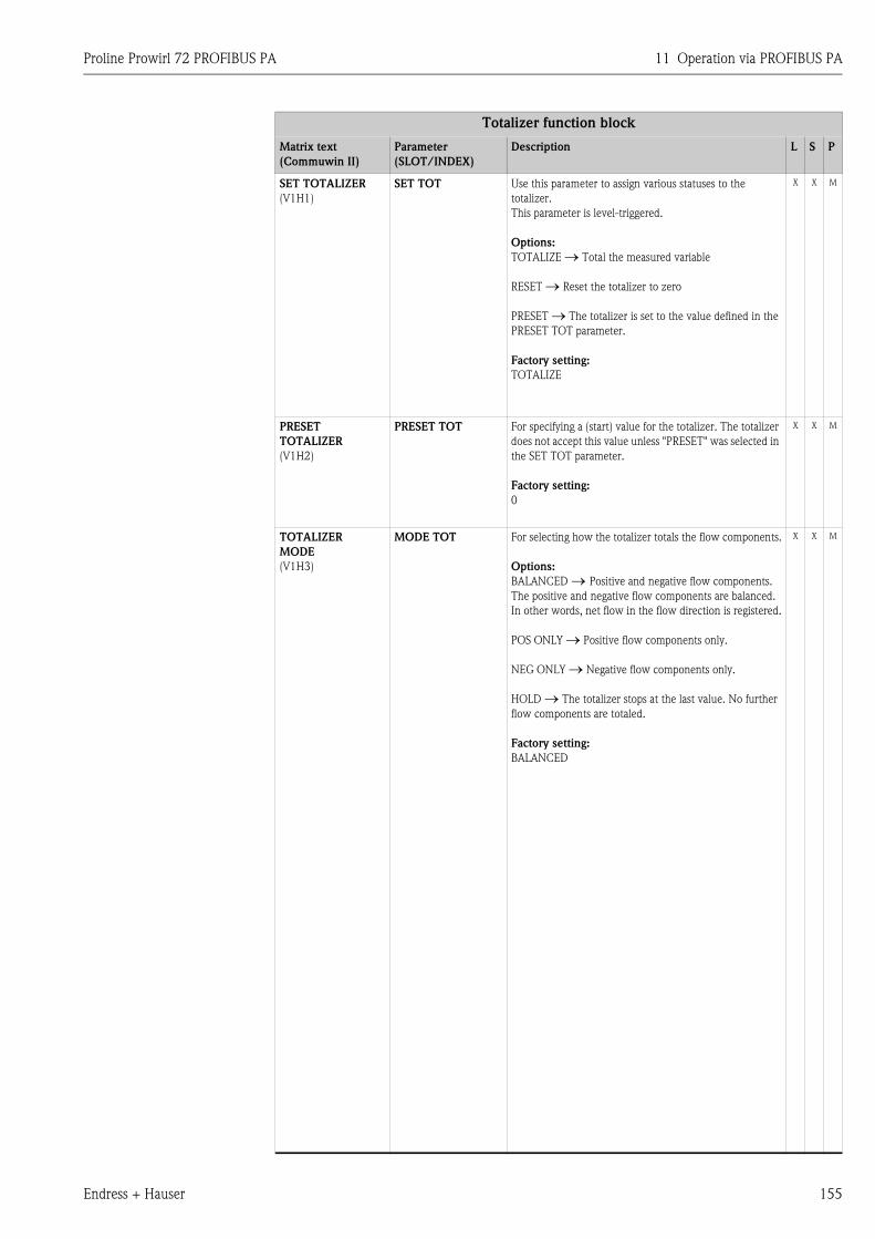
Proline Prowirl 72 PROFIBUS PA 11 Operation via PROFIBUS PA
Endress + Hauser 155
SET TOTALIZER
(V1H1)
SET TOT Use this parameter to assign various statuses to the
totalizer.
This parameter is level-triggered.
Options:
TOTALIZE → Total the measured variable
RESET → Reset the totalizer to zero
PRESET → The totalizer is set to the value defined in the
PRESET TOT parameter.
Factory setting:
TOTALIZE
X X M
PRESET
TOTALIZER
(V1H2)
PRESET TOT For specifying a (start) value for the totalizer. The totalizer
does not accept this value unless "PRESET" was selected in
the SET TOT parameter.
Factory setting:
0
X X M
TOTALIZER
MODE
(V1H3)
MODE TOT For selecting how the totalizer totals the flow components.
Options:
BALANCED → Positive and negative flow components.
The positive and negative flow components are balanced.
In other words, net flow in the flow direction is registered.
POS ONLY → Positive flow components only.
NEG ONLY → Negative flow components only.
HOLD → The totalizer stops at the last value. No further
flow components are totaled.
Factory setting:
BALANCED
X X M
Totalizer function block
Matrix text
(Commuwin II)
Parameter
(SLOT/INDEX)
Description L S P
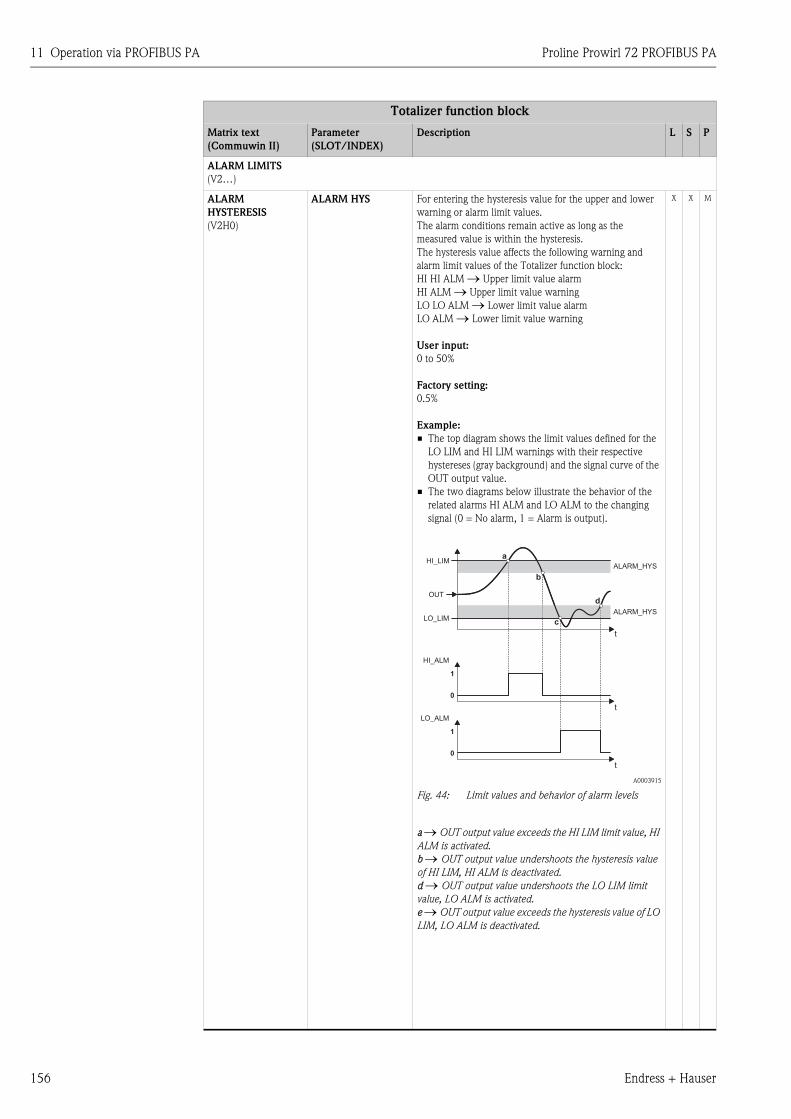
11 Operation via PROFIBUS PA Proline Prowirl 72 PROFIBUS PA
156 Endress + Hauser
ALARM LIMITS
(V2…)
ALARM
HYSTERESIS
(V2H0)
ALARM HYS For entering the hysteresis value for the upper and lower
warning or alarm limit values.
The alarm conditions remain active as long as the
measured value is within the hysteresis.
The hysteresis value affects the following warning and
alarm limit values of the Totalizer function block:
HI HI ALM → Upper limit value alarm
HI ALM → Upper limit value warning
LO LO ALM → Lower limit value alarm
LO ALM → Lower limit value warning
User input:
0 to 50%
Factory setting:
0.5%
Example:
• The top diagram shows the limit values defined for the
LO LIM and HI LIM warnings with their respective
hystereses (gray background) and the signal curve of the
OUT output value.
• The two diagrams below illustrate the behavior of the
related alarms HI ALM and LO ALM to the changing
signal (0 = No alarm, 1 = Alarm is output).
A0003915
Fig. 44: Limit values and behavior of alarm levels
a → OUT output value exceeds the HI LIM limit value, HI
ALM is activated.
b → OUT output value undershoots the hysteresis value
of HI LIM, HI ALM is deactivated.
d → OUT output value undershoots the LO LIM limit
value, LO ALM is activated.
e → OUT output value exceeds the hysteresis value of LO
LIM, LO ALM is deactivated.
X X M
Totalizer function block
Matrix text
(Commuwin II)
Parameter
(SLOT/INDEX)
Description L S P
ALARM_HYS
ALARM_HYS
t
t
t
HI_ALM
LO_ALM
1
a
b
c
d
1
0
0
HI_LIM
LO_LIM
OUT
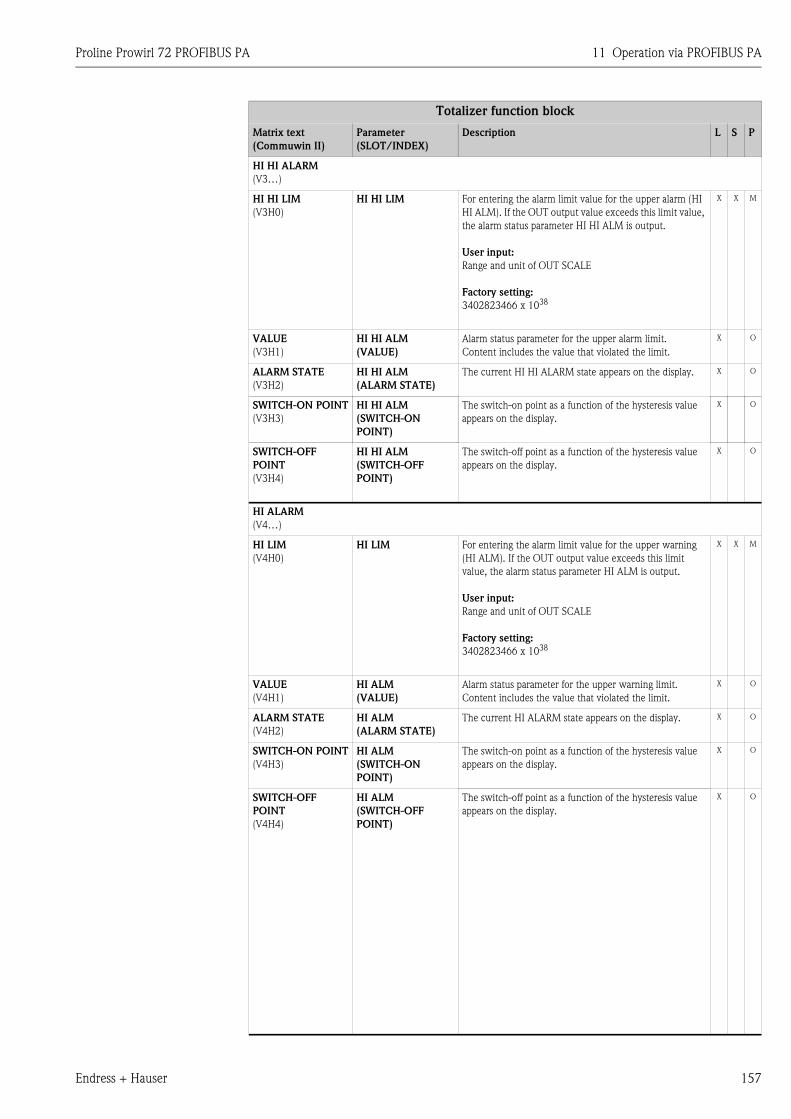
Proline Prowirl 72 PROFIBUS PA 11 Operation via PROFIBUS PA
Endress + Hauser 157
HI HI ALARM
(V3…)
HI HI LIM
(V3H0)
HI HI LIM For entering the alarm limit value for the upper alarm (HI
HI ALM). If the OUT output value exceeds this limit value,
the alarm status parameter HI HI ALM is output.
User input:
Range and unit of OUT SCALE
Factory setting:
3402823466 x 1038
X X M
VALUE
(V3H1)
HI HI ALM
(VALUE)
Alarm status parameter for the upper alarm limit.
Content includes the value that violated the limit.
X O
ALARM STATE
(V3H2)
HI HI ALM
(ALARM STATE)
The current HI HI ALARM state appears on the display. X O
SWITCH-ON POINT
(V3H3)
HI HI ALM
(SWITCH-ON
POINT)
The switch-on point as a function of the hysteresis value
appears on the display.
X O
SWITCH-OFF
POINT
(V3H4)
HI HI ALM
(SWITCH-OFF
POINT)
The switch-off point as a function of the hysteresis value
appears on the display.
X O
HI ALARM
(V4…)
HI LIM
(V4H0)
HI LIM For entering the alarm limit value for the upper warning
(HI ALM). If the OUT output value exceeds this limit
value, the alarm status parameter HI ALM is output.
User input:
Range and unit of OUT SCALE
Factory setting:
3402823466 x 1038
X X M
VALUE
(V4H1)
HI ALM
(VALUE)
Alarm status parameter for the upper warning limit.
Content includes the value that violated the limit.
X O
ALARM STATE
(V4H2)
HI ALM
(ALARM STATE)
The current HI ALARM state appears on the display. X O
SWITCH-ON POINT
(V4H3)
HI ALM
(SWITCH-ON
POINT)
The switch-on point as a function of the hysteresis value
appears on the display.
X O
SWITCH-OFF
POINT
(V4H4)
HI ALM
(SWITCH-OFF
POINT)
The switch-off point as a function of the hysteresis value
appears on the display.
X O
Totalizer function block
Matrix text
(Commuwin II)
Parameter
(SLOT/INDEX)
Description L S P
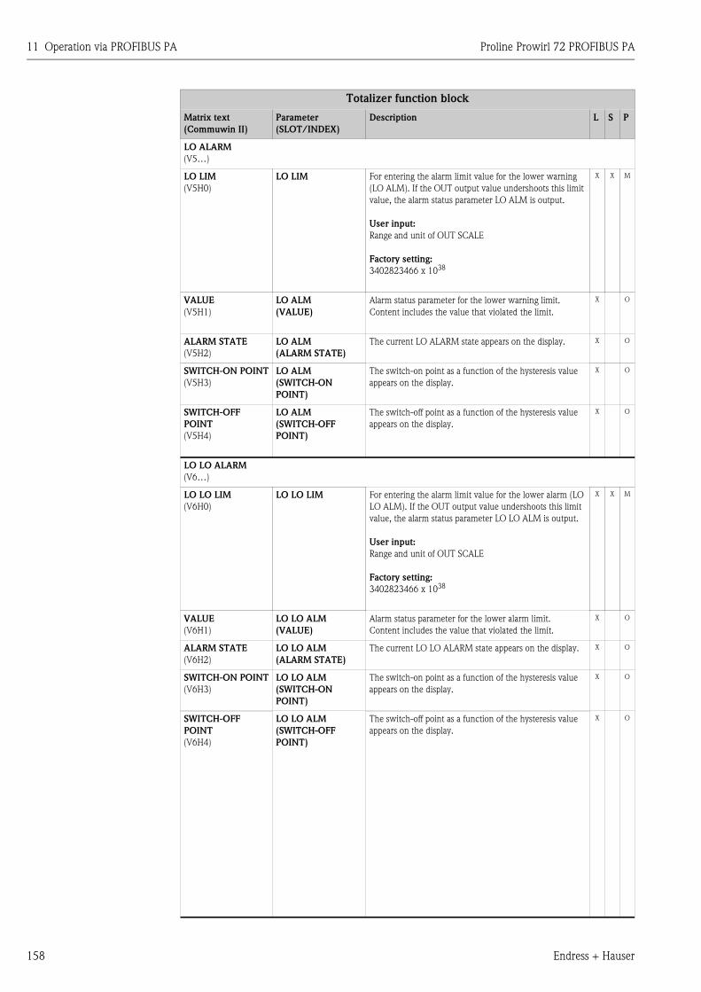
11 Operation via PROFIBUS PA Proline Prowirl 72 PROFIBUS PA
158 Endress + Hauser
LO ALARM
(V5…)
LO LIM
(V5H0)
LO LIM For entering the alarm limit value for the lower warning
(LO ALM). If the OUT output value undershoots this limit
value, the alarm status parameter LO ALM is output.
User input:
Range and unit of OUT SCALE
Factory setting:
3402823466 x 1038
X X M
VALUE
(V5H1)
LO ALM
(VALUE)
Alarm status parameter for the lower warning limit.
Content includes the value that violated the limit.
X O
ALARM STATE
(V5H2)
LO ALM
(ALARM STATE)
The current LO ALARM state appears on the display. X O
SWITCH-ON POINT
(V5H3)
LO ALM
(SWITCH-ON
POINT)
The switch-on point as a function of the hysteresis value
appears on the display.
X O
SWITCH-OFF
POINT
(V5H4)
LO ALM
(SWITCH-OFF
POINT)
The switch-off point as a function of the hysteresis value
appears on the display.
X O
LO LO ALARM
(V6…)
LO LO LIM
(V6H0)
LO LO LIM For entering the alarm limit value for the lower alarm (LO
LO ALM). If the OUT output value undershoots this limit
value, the alarm status parameter LO LO ALM is output.
User input:
Range and unit of OUT SCALE
Factory setting:
3402823466 x 1038
X X M
VALUE
(V6H1)
LO LO ALM
(VALUE)
Alarm status parameter for the lower alarm limit.
Content includes the value that violated the limit.
X O
ALARM STATE
(V6H2)
LO LO ALM
(ALARM STATE)
The current LO LO ALARM state appears on the display. X O
SWITCH-ON POINT
(V6H3)
LO LO ALM
(SWITCH-ON
POINT)
The switch-on point as a function of the hysteresis value
appears on the display.
X O
SWITCH-OFF
POINT
(V6H4)
LO LO ALM
(SWITCH-OFF
POINT)
The switch-off point as a function of the hysteresis value
appears on the display.
X O
Totalizer function block
Matrix text
(Commuwin II)
Parameter
(SLOT/INDEX)
Description L S P
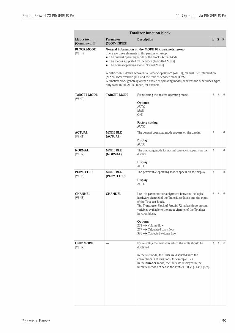
Proline Prowirl 72 PROFIBUS PA 11 Operation via PROFIBUS PA
Endress + Hauser 159
BLOCK MODE
(V8…)
General information on the MODE BLK parameter group:
There are three elements in this parameter group:
• The current operating mode of the block (Actual Mode)
• The modes supported by the block (Permitted Mode)
• The normal operating mode (Normal Mode)
A distinction is drawn between "automatic operation" (AUTO), manual user intervention
(MAN), local override (LO) and the "out-of-service" mode (O/S).
A function block generally offers a choice of operating modes, whereas the other block types
only work in the AUTO mode, for example.
TARGET MODE
(V8H0)
TARGET MODE For selecting the desired operating mode.
Options:
AUTO
MAN
O/S
Factory setting:
AUTO
X X M
ACTUAL
(V8H1)
MODE BLK
(ACTUAL)
The current operating mode appears on the display.
Display:
AUTO
X M
NORMAL
(V8H2)
MODE BLK
(NORMAL)
The operating mode for normal operation appears on the
display.
Display:
AUTO
X M
PERMITTED
(V8H3)
MODE BLK
(PERMITTED)
The permissible operating modes appear on the display.
Display:
AUTO
X M
CHANNEL
(V8H5)
CHANNEL Use this parameter for assignment between the logical
hardware channel of the Transducer Block and the input
of the Totalizer Block.
The Transducer Block of Prowirl 72 makes three process
variables available to the input channel of the Totalizer
function block.
Options:
273 → Volume flow
277 → Calculated mass flow
398 → Corrected volume flow
X X M
UNIT MODE
(V8H7)
— For selecting the format in which the units should be
displayed.
In the list mode, the units are displayed with the
conventional abbreviations, for example: L/s.
In the number mode, the units are displayed in the
numerical code defined in the Profiles 3.0, e.g. 1351 (L/s).
X X O
Totalizer function block
Matrix text
(Commuwin II)
Parameter
(SLOT/INDEX)
Description L S P
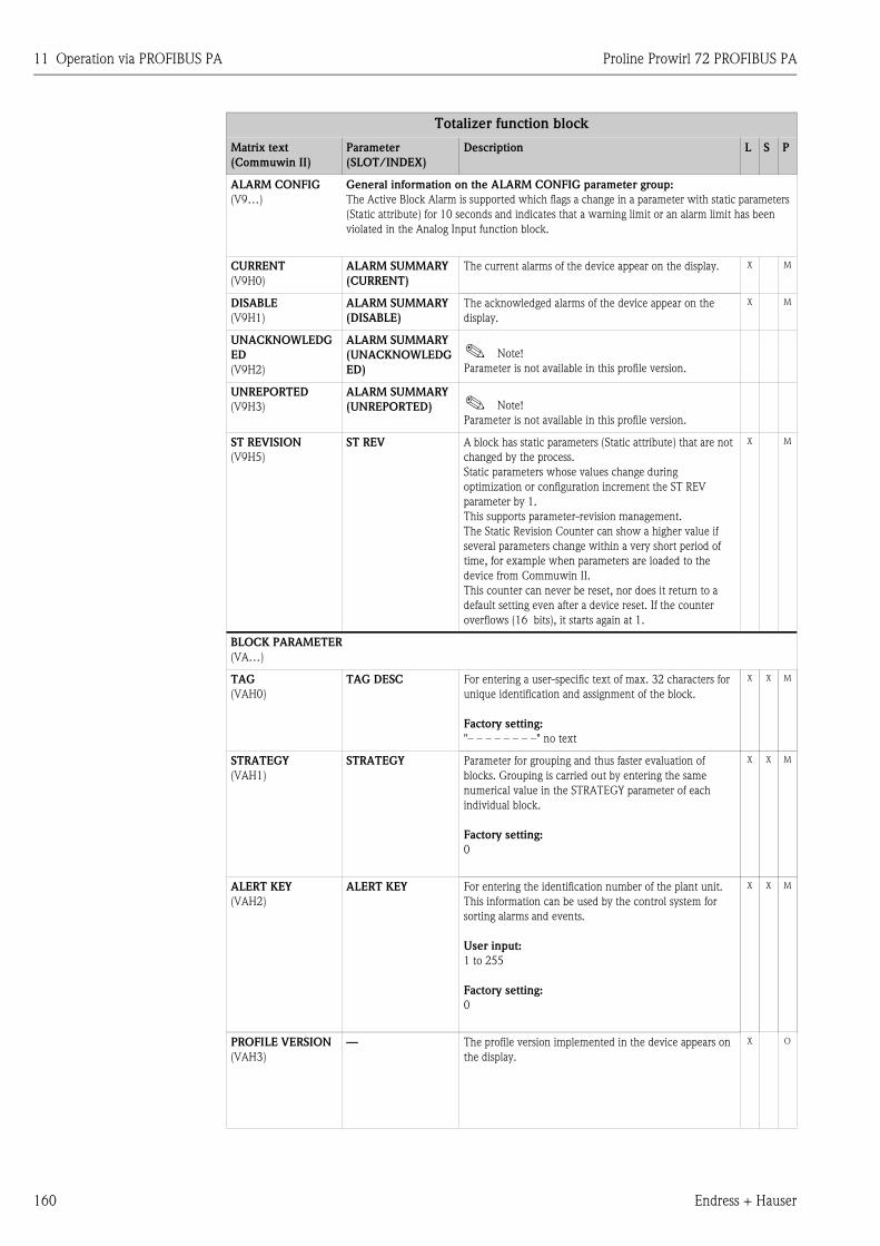
11 Operation via PROFIBUS PA Proline Prowirl 72 PROFIBUS PA
160 Endress + Hauser
ALARM CONFIG
(V9…)
General information on the ALARM CONFIG parameter group:
The Active Block Alarm is supported which flags a change in a parameter with static parameters
(Static attribute) for 10 seconds and indicates that a warning limit or an alarm limit has been
violated in the Analog Input function block.
CURRENT
(V9H0)
ALARM SUMMARY
(CURRENT)
The current alarms of the device appear on the display. X M
DISABLE
(V9H1)
ALARM SUMMARY
(DISABLE)
The acknowledged alarms of the device appear on the
display.
X M
UNACKNOWLEDG
ED
(V9H2)
ALARM SUMMARY
(UNACKNOWLEDG
ED)
! Note!
Parameter is not available in this profile version.
UNREPORTED
(V9H3)
ALARM SUMMARY
(UNREPORTED) ! Note!
Parameter is not available in this profile version.
ST REVISION
(V9H5)
ST REV A block has static parameters (Static attribute) that are not
changed by the process.
Static parameters whose values change during
optimization or configuration increment the ST REV
parameter by 1.
This supports parameter-revision management.
The Static Revision Counter can show a higher value if
several parameters change within a very short period of
time, for example when parameters are loaded to the
device from Commuwin II.
This counter can never be reset, nor does it return to a
default setting even after a device reset. If the counter
overflows (16 bits), it starts again at 1.
X M
BLOCK PARAMETER
(VA…)
TAG
(VAH0)
TAG DESC For entering a user-specific text of max. 32 characters for
unique identification and assignment of the block.
Factory setting:
"– – – – – – – –" no text
X X M
STRATEGY
(VAH1)
STRATEGY Parameter for grouping and thus faster evaluation of
blocks. Grouping is carried out by entering the same
numerical value in the STRATEGY parameter of each
individual block.
Factory setting:
0
X X M
ALERT KEY
(VAH2)
ALERT KEY For entering the identification number of the plant unit.
This information can be used by the control system for
sorting alarms and events.
User input:
1 to 255
Factory setting:
0
X X M
PROFILE VERSION
(VAH3)
— The profile version implemented in the device appears on
the display.
X O
Totalizer function block
Matrix text
(Commuwin II)
Parameter
(SLOT/INDEX)
Description L S P
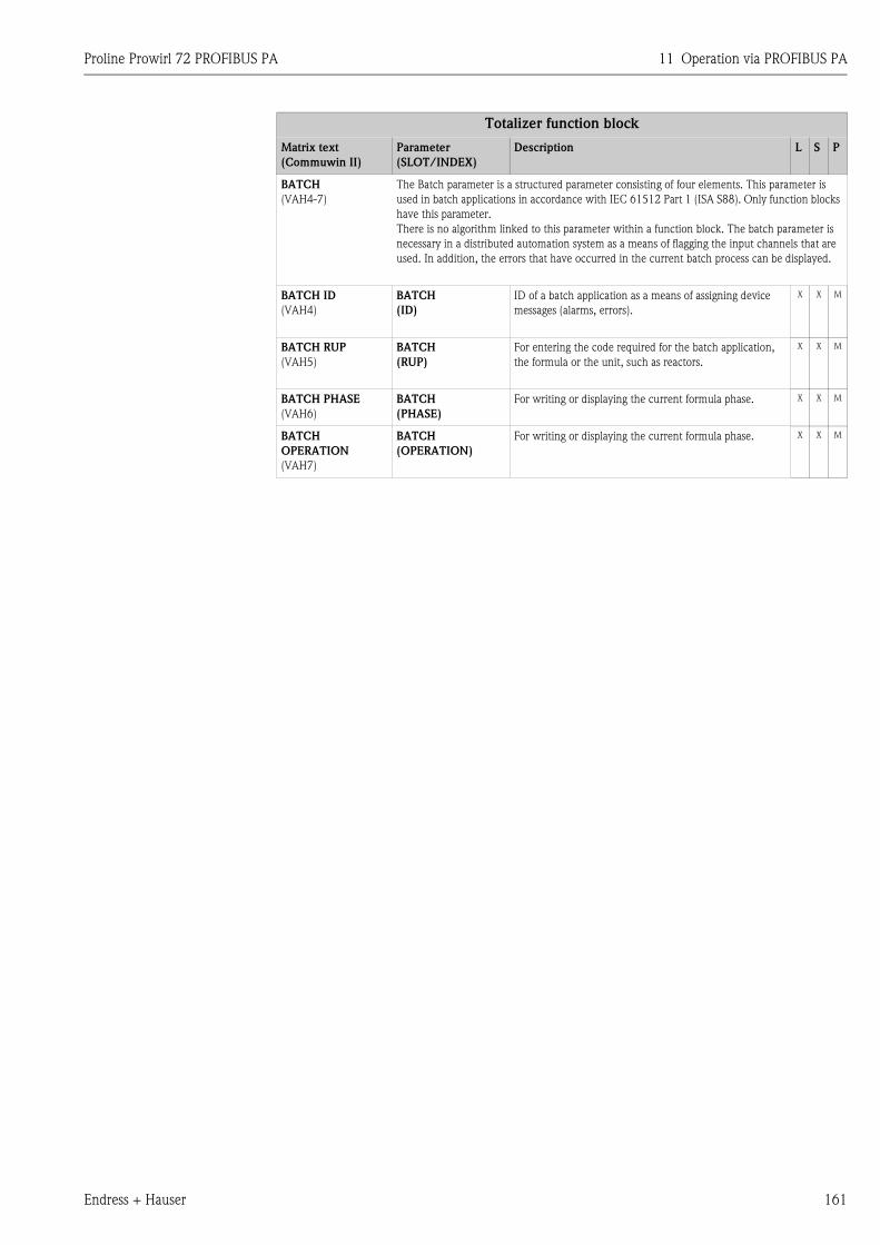
Proline Prowirl 72 PROFIBUS PA 11 Operation via PROFIBUS PA
Endress + Hauser 161
BATCH
(VAH4-7)
The Batch parameter is a structured parameter consisting of four elements. This parameter is
used in batch applications in accordance with IEC 61512 Part 1 (ISA S88). Only function blocks
have this parameter.
There is no algorithm linked to this parameter within a function block. The batch parameter is
necessary in a distributed automation system as a means of flagging the input channels that are
used. In addition, the errors that have occurred in the current batch process can be displayed.
BATCH ID
(VAH4)
BATCH
(ID)
ID of a batch application as a means of assigning device
messages (alarms, errors).
X X M
BATCH RUP
(VAH5)
BATCH
(RUP)
For entering the code required for the batch application,
the formula or the unit, such as reactors.
X X M
BATCH PHASE
(VAH6)
BATCH
(PHASE)
For writing or displaying the current formula phase. X X M
BATCH
OPERATION
(VAH7)
BATCH
(OPERATION)
For writing or displaying the current formula phase. X X M
Totalizer function block
Matrix text
(Commuwin II)
Parameter
(SLOT/INDEX)
Description L S P
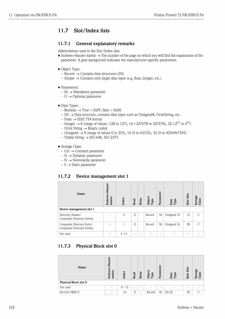
11 Operation via PROFIBUS PA Proline Prowirl 72 PROFIBUS PA
162 Endress + Hauser
11.7 Slot/Index lists
11.7.1 General explanatory remarks
Abbreviations used in the Slot/Index lists:
• Endress+Hauser matrix → The number of the page on which you will find the explanation of the
parameter. A gray background indicates the manufacturer-specific parameters.
• Object Type:
– Record → Contains data structures (DS)
– Simple → Contains only single data types (e.g. float, integer, etc.)
• Parameters:
– M → Mandatory parameter
– O → Optional parameter
• Data Types:
– Boolean → True = 0xFF, false = 0x00
– DS → Data structure, contains data types such as Unsigned8, OctetString, etc.
– Float → IEEE 754 format
– Integer → 8 (range of values -128 to 127), 16 (-327678 to 327678), 32 (-231 to 231)
– Octet String → Binary coded
– Unsigned → 8 (range of values 0 to 255), 16 (0 to 65535), 32 (0 to 4294967295)
– Visible String → ISO 646, ISO 2375
• Storage Class:
– Cst → Constant parameter
– D → Dynamic parameter
– N → Nonvolatile parameter
– S → Static parameter
11.7.2 Device management slot 1
11.7.3 Physical Block slot 0
Name
En
dre
ss+
Hause
r
matr
ix
Index
Read
Wri
te
Obje
ct
Type
Para
mete
r
Data
Type
Byte
Siz
e
Sto
rage
Cla
ss
Device management slot 1
Directory Header/
Composite Directory Entries
– 0 X Record M Unsigned 16 12 C
Composite Directory Entry/
Composite Directory Entries
– 1 X Record M Unsigned 16 28 C
Not used – 2 -15 – – – – – – –
Name
En
dre
ss+
Hau
ser
matr
ix
Ind
ex
Read
Wri
te
Ob
ject
Typ
e
Para
mete
r
Data
Typ
e
Byte
Siz
e
Sto
rage
Cla
ss
Physical Block slot 0
Not used – 0 - 15 – – – – – – –
BLOCK OBJECT – 16 X – Record M DS-32 20 C
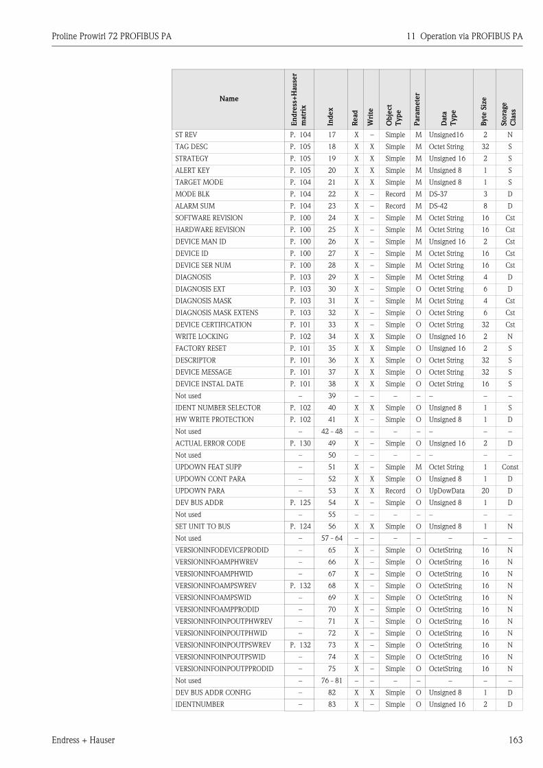
Proline Prowirl 72 PROFIBUS PA 11 Operation via PROFIBUS PA
Endress + Hauser 163
ST REV P. 104 17 X – Simple M Unsigned16 2 N
TAG DESC P. 105 18 X X Simple M Octet String 32 S
STRATEGY P. 105 19 X X Simple M Unsigned 16 2 S
ALERT KEY P. 105 20 X X Simple M Unsigned 8 1 S
TARGET MODE P. 104 21 X X Simple M Unsigned 8 1 S
MODE BLK P. 104 22 X – Record M DS-37 3 D
ALARM SUM P. 104 23 X – Record M DS-42 8 D
SOFTWARE REVISION P. 100 24 X – Simple M Octet String 16 Cst
HARDWARE REVISION P. 100 25 X – Simple M Octet String 16 Cst
DEVICE MAN ID P. 100 26 X – Simple M Unsigned 16 2 Cst
DEVICE ID P. 100 27 X – Simple M Octet String 16 Cst
DEVICE SER NUM P. 100 28 X – Simple M Octet String 16 Cst
DIAGNOSIS P. 103 29 X – Simple M Octet String 4 D
DIAGNOSIS EXT P. 103 30 X – Simple O Octet String 6 D
DIAGNOSIS MASK P. 103 31 X – Simple M Octet String 4 Cst
DIAGNOSIS MASK EXTENS P. 103 32 X – Simple O Octet String 6 Cst
DEVICE CERTIFICATION P. 101 33 X – Simple O Octet String 32 Cst
WRITE LOCKING P. 102 34 X X Simple O Unsigned 16 2 N
FACTORY RESET P. 101 35 X X Simple O Unsigned 16 2 S
DESCRIPTOR P. 101 36 X X Simple O Octet String 32 S
DEVICE MESSAGE P. 101 37 X X Simple O Octet String 32 S
DEVICE INSTAL DATE P. 101 38 X X Simple O Octet String 16 S
Not used – 39 – – – – – – –
IDENT NUMBER SELECTOR P. 102 40 X X Simple O Unsigned 8 1 S
HW WRITE PROTECTION P. 102 41 X – Simple O Unsigned 8 1 D
Not used – 42 - 48 – – – – – – –
ACTUAL ERROR CODE P. 130 49 X – Simple O Unsigned 16 2 D
Not used – 50 – – – – – – –
UPDOWN FEAT SUPP – 51 X – Simple M Octet String 1 Const
UPDOWN CONT PARA – 52 X X Simple O Unsigned 8 1 D
UPDOWN PARA – 53 X X Record O UpDowData 20 D
DEV BUS ADDR P. 125 54 X – Simple O Unsigned 8 1 D
Not used – 55 – – – – – – –
SET UNIT TO BUS P. 124 56 X X Simple O Unsigned 8 1 N
Not used – 57 - 64 – – – – – – –
VERSIONINFODEVICEPRODID – 65 X – Simple O OctetString 16 N
VERSIONINFOAMPHWREV – 66 X – Simple O OctetString 16 N
VERSIONINFOAMPHWID – 67 X – Simple O OctetString 16 N
VERSIONINFOAMPSWREV P. 132 68 X – Simple O OctetString 16 N
VERSIONINFOAMPSWID – 69 X – Simple O OctetString 16 N
VERSIONINFOAMPPRODID – 70 X – Simple O OctetString 16 N
VERSIONINFOINPOUTPHWREV – 71 X – Simple O OctetString 16 N
VERSIONINFOINPOUTPHWID – 72 X – Simple O OctetString 16 N
VERSIONINFOINPOUTPSWREV P. 132 73 X – Simple O OctetString 16 N
VERSIONINFOINPOUTPSWID – 74 X – Simple O OctetString 16 N
VERSIONINFOINPOUTPPRODID – 75 X – Simple O OctetString 16 N
Not used – 76 - 81 – – – – – – –
DEV BUS ADDR CONFIG – 82 X X Simple O Unsigned 8 1 D
IDENTNUMBER – 83 X – Simple O Unsigned 16 2 D
Name
En
dre
ss+
Hau
ser
matr
ix
Index
Read
Wri
te
Obje
ct
Type
Para
mete
r
Data
Type
Byte
Siz
e
Sto
rage
Cla
ss
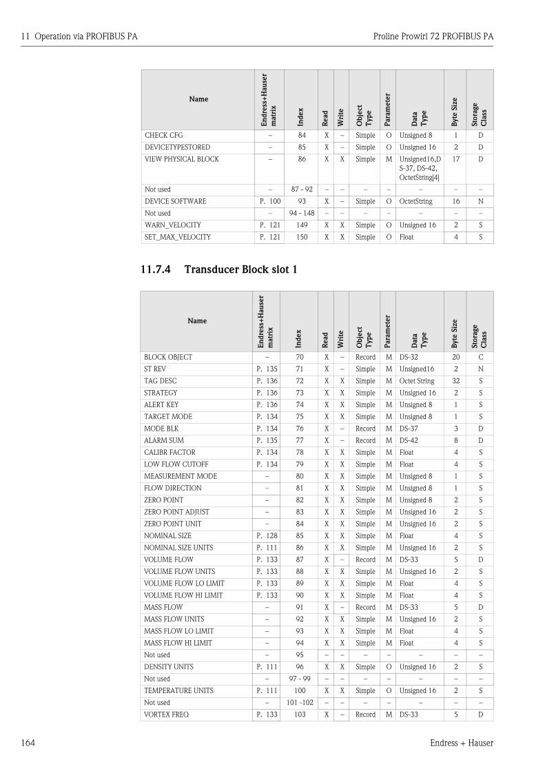
11 Operation via PROFIBUS PA Proline Prowirl 72 PROFIBUS PA
164 Endress + Hauser
11.7.4 Transducer Block slot 1
CHECK CFG – 84 X – Simple O Unsigned 8 1 D
DEVICETYPESTORED – 85 X – Simple O Unsigned 16 2 D
VIEW PHYSICAL BLOCK – 86 X X Simple M Unsigned16,D
S-37, DS-42,
OctetString[4]
17 D
Not used – 87 - 92 – – – – – – –
DEVICE SOFTWARE P. 100 93 X – Simple O OctetString 16 N
Not used – 94 - 148 – – – – – – –
WARN_VELOCITY P. 121 149 X X Simple O Unsigned 16 2 S
SET_MAX_VELOCITY P. 121 150 X X Simple O Float 4 S
Name
En
dre
ss+
Hau
ser
matr
ix
Ind
ex
Read
Wri
te
Ob
ject
Typ
e
Para
mete
r
Data
Typ
e
Byte
Siz
e
Sto
rage
Cla
ss
BLOCK OBJECT – 70 X – Record M DS-32 20 C
ST REV P. 135 71 X – Simple M Unsigned16 2 N
TAG DESC P. 136 72 X X Simple M Octet String 32 S
STRATEGY P. 136 73 X X Simple M Unsigned 16 2 S
ALERT KEY P. 136 74 X X Simple M Unsigned 8 1 S
TARGET MODE P. 134 75 X X Simple M Unsigned 8 1 S
MODE BLK P. 134 76 X – Record M DS-37 3 D
ALARM SUM P. 135 77 X – Record M DS-42 8 D
CALIBR FACTOR P. 134 78 X X Simple M Float 4 S
LOW FLOW CUTOFF P. 134 79 X X Simple M Float 4 S
MEASUREMENT MODE – 80 X X Simple M Unsigned 8 1 S
FLOW DIRECTION – 81 X X Simple M Unsigned 8 1 S
ZERO POINT – 82 X X Simple M Unsigned 8 2 S
ZERO POINT ADJUST – 83 X X Simple M Unsigned 16 2 S
ZERO POINT UNIT – 84 X X Simple M Unsigned 16 2 S
NOMINAL SIZE P. 128 85 X X Simple M Float 4 S
NOMINAL SIZE UNITS P. 111 86 X X Simple M Unsigned 16 2 S
VOLUME FLOW P. 133 87 X – Record M DS-33 5 D
VOLUME FLOW UNITS P. 133 88 X X Simple M Unsigned 16 2 S
VOLUME FLOW LO LIMIT P. 133 89 X X Simple M Float 4 S
VOLUME FLOW HI LIMIT P. 133 90 X X Simple M Float 4 S
MASS FLOW – 91 X – Record M DS-33 5 D
MASS FLOW UNITS – 92 X X Simple M Unsigned 16 2 S
MASS FLOW LO LIMIT – 93 X X Simple M Float 4 S
MASS FLOW HI LIMIT – 94 X X Simple M Float 4 S
Not used – 95 – – – – – – –
DENSITY UNITS P. 111 96 X X Simple O Unsigned 16 2 S
Not used – 97 - 99 – – – – – – –
TEMPERATURE UNITS P. 111 100 X X Simple O Unsigned 16 2 S
Not used – 101 -102 – – – – – – –
VORTEX FREQ P. 133 103 X – Record M DS-33 5 D
Name
En
dre
ss+
Hau
ser
matr
ix
Index
Read
Wri
te
Obje
ct
Type
Para
mete
r
Data
Type
Byte
Siz
e
Sto
rage
Cla
ss
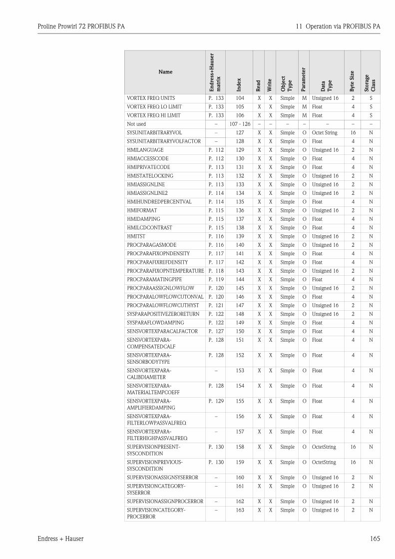
Proline Prowirl 72 PROFIBUS PA 11 Operation via PROFIBUS PA
Endress + Hauser 165
VORTEX FREQ UNITS P. 133 104 X X Simple M Unsigned 16 2 S
VORTEX FREQ LO LIMIT P. 133 105 X X Simple M Float 4 S
VORTEX FREQ HI LIMIT P. 133 106 X X Simple M Float 4 S
Not used – 107 - 126 – – – – – – –
SYSUNITARBITRARYVOL – 127 X X Simple O Octet String 16 N
SYSUNITARBITRARYVOLFACTOR – 128 X X Simple O Float 4 N
HMILANGUAGE P. 112 129 X X Simple O Unsigned 16 2 N
HMIACCESSCODE P. 112 130 X X Simple O Float 4 N
HMIPRIVATECODE P. 113 131 X X Simple O Float 4 N
HMISTATELOCKING P. 113 132 X X Simple O Unsigned 16 2 N
HMIASSIGNLINE P. 113 133 X X Simple O Unsigned 16 2 N
HMIASSIGNLINE2 P. 114 134 X X Simple O Unsigned 16 2 N
HMIHUNDREDPERCENTVAL P. 114 135 X X Simple O Float 4 N
HMIFORMAT P. 115 136 X X Simple O Unsigned 16 2 N
HMIDAMPING P. 115 137 X X Simple O Float 4 N
HMILCDCONTRAST P. 115 138 X X Simple O Float 4 N
HMITST P. 116 139 X X Simple O Unsigned 16 2 N
PROCPARAGASMODE P. 116 140 X X Simple O Unsigned 16 2 N
PROCPARAFIXOPNDENSITY P. 117 141 X X Simple O Float 4 N
PROCPARAFIXREFDENSITY P. 117 142 X X Simple O Float 4 N
PROCPARAFIXOPNTEMPERATURE P. 118 143 X X Simple O Unsigned 16 2 N
PROCPARAMATINGPIPE P. 119 144 X X Simple O Float 4 N
PROCPARAASSIGNLOWFLOW P. 120 145 X X Simple O Unsigned 16 2 N
PROCPARALOWFLOWCUTONVAL P. 120 146 X X Simple O Float 4 N
PROCPARALOWFLOWCUTHYST P. 121 147 X X Simple O Unsigned 16 2 N
SYSPARAPOSITIVEZERORETURN P. 122 148 X X Simple O Unsigned 16 2 N
SYSPARAFLOWDAMPING P. 122 149 X X Simple O Float 4 N
SENSVORTEXPARACALFACTOR P. 127 150 X X Simple O Float 4 N
SENSVORTEXPARA-
COMPENSATEDCALF
P. 128 151 X X Simple O Float 4 N
SENSVORTEXPARA-
SENSORBODYTYPE
P. 128 152 X X Simple O Float 4 N
SENSVORTEXPARA-
CALIBDIAMETER
– 153 X X Simple O Float 4 N
SENSVORTEXPARA-
MATERIALTEMPCOEFF
P. 128 154 X X Simple O Float 4 N
SENSVORTEXPARA-
AMPLIFIERDAMPING
P. 129 155 X X Simple O Float 4 N
SENSVORTEXPARA-
FILTERLOWPASSVALFREQ
– 156 X X Simple O Float 4 N
SENSVORTEXPARA-
FILTERHIGHPASSVALFREQ
– 157 X X Simple O Float 4 N
SUPERVISIONPRESENT-
SYSCONDITION
P. 130 158 X X Simple O OctetString 16 N
SUPERVISIONPREVIOUS-
SYSCONDITION
P. 130 159 X X Simple O OctetString 16 N
SUPERVISIONASSIGNSYSERROR – 160 X X Simple O Unsigned 16 2 N
SUPERVISIONCATEGORY-
SYSERROR
– 161 X X Simple O Unsigned 16 2 N
SUPERVISIONASSIGNPROCERROR – 162 X X Simple O Unsigned 16 2 N
SUPERVISIONCATEGORY-
PROCERROR
– 163 X X Simple O Unsigned 16 2 N
Name
En
dre
ss+
Hau
ser
matr
ix
Index
Read
Wri
te
Obje
ct
Type
Para
mete
r
Data
Type
Byte
Siz
e
Sto
rage
Cla
ss
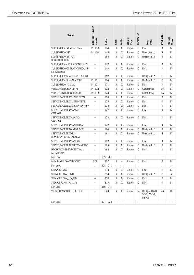
11 Operation via PROFIBUS PA Proline Prowirl 72 PROFIBUS PA
166 Endress + Hauser
SUPERVISIONALARMDELAY P. 130 164 X X Simple O Float 4 N
SUPERVISIONRST P. 130 165 X X Simple O Unsigned 16 2 N
SUPERVISIONRSTFCT-
BLOCKFAILURE
– 166 X X Simple O Unsigned 16 2 N
SUPERVISIONOPERATIONHOURS – 167 X X Simple O Float 4 N
SUPERVISIONOPERATIONHOURS-
SINCERESET
– 168 X X Simple O Float 4 N
SUPERVISIONSIMFAILSAFEMODE – 169 X X Simple O Unsigned 16 2 N
SUPERVISIONSIMMEASVAR P. 131 170 X X Simple O Unsigned 16 2 N
SUPERVISIONSIMVAL P. 131 171 X X Simple O Float 4 N
VERSIONINFOSENSTYPE P. 132 172 X X Simple O OctetString 16 N
VERSIONINFODSCSENSNR P. 132 173 X X Simple O OctetString 16 N
SERVICEVORTEXCURRENTSV1 – 174 X X Simple O Float 4 N
SERVICEVORTEXCURRENTSV2 – 175 X X Simple O Float 4 N
SERVICEVORTEXCURRENTDIFFSV – 176 X X Simple O Float 4 N
SERVICEVORTEXMAXSV1-
CHANGE
– 177 X X Simple O Float 4 N
SERVICEVORTEXMAXSV2-
CHANGE
– 178 X X Simple O Float 4 N
SERVICEVORTEXMAXDIFFSV – 179 X X Simple O Float 4 N
SERVICEVORTEXWARNLEVEL – 180 X X Simple O Unsigned 16 2 N
SERVICEVORTEXDSC-
RESONANCEFREQALARM
– 181 X X Simple O Unsigned 16 2 N
SERVICEVORTEXMAXFREQ – 182 X X Simple O Float 4 N
SERVICEVORTEXRESETMAXFREQ – 183 X X Simple O Unsigned 16 2 N
HMIHUNDREDPERCENTVAL-
MULTMAIN
– 184 X X Simple O Float 4 N
Not used – 185 - 206 – – – – – – –
MEASVARFLOWVELOCITY 121 207 X – Simple O Float 4 N
Not used – 208 - 211 – – – – – – –
STDVOLFLOW – 212 X X Simple O Float 4 N
STDVOLFLOW_UNIT – 213 X X Simple O Unsigned 16 2 S
STDVOLFLOW_LO_LIM – 214 X X Simple O Float 4 N
STDVOLFLOW_HI_LIM – 215 X X Simple O Float 4 N
Not used – 216 - 219 – – – – – – –
VIEW_TRANSDUCER BLOCK – 220 X X Simple M Unsigned16,D
S-37, DS-33,
DS-42
23 D
Not used – 221 - 223 – – – – – – –
Name
En
dre
ss+
Hau
ser
matr
ix
Index
Read
Wri
te
Obje
ct
Type
Para
mete
r
Data
Type
Byte
Siz
e
Sto
rage
Cla
ss
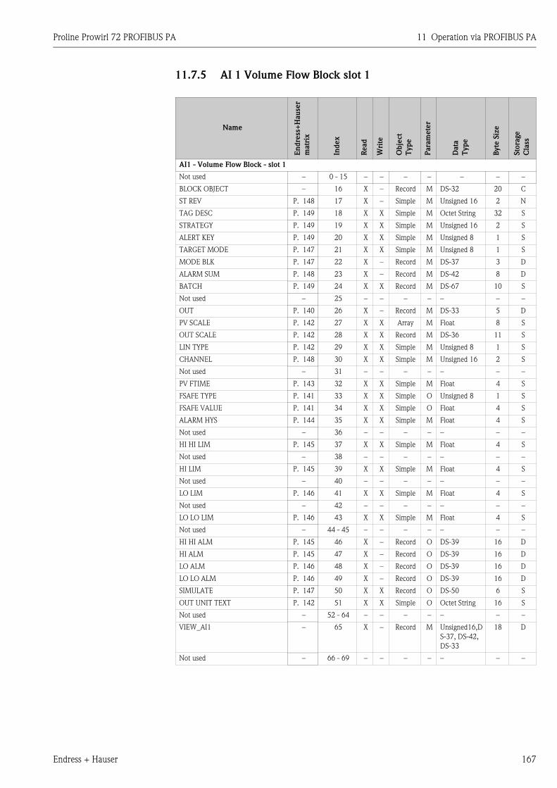
Proline Prowirl 72 PROFIBUS PA 11 Operation via PROFIBUS PA
Endress + Hauser 167
11.7.5 AI 1 Volume Flow Block slot 1
Name
En
dre
ss+
Hau
ser
matr
ix
Index
Read
Wri
te
Ob
ject
Type
Para
mete
r
Data
Type
Byte
Siz
e
Sto
rage
Cla
ss
AI1 - Volume Flow Block - slot 1
Not used – 0 - 15 – – – – – – –
BLOCK OBJECT – 16 X – Record M DS-32 20 C
ST REV P. 148 17 X – Simple M Unsigned 16 2 N
TAG DESC P. 149 18 X X Simple M Octet String 32 S
STRATEGY P. 149 19 X X Simple M Unsigned 16 2 S
ALERT KEY P. 149 20 X X Simple M Unsigned 8 1 S
TARGET MODE P. 147 21 X X Simple M Unsigned 8 1 S
MODE BLK P. 147 22 X – Record M DS-37 3 D
ALARM SUM P. 148 23 X – Record M DS-42 8 D
BATCH P. 149 24 X X Record M DS-67 10 S
Not used – 25 – – – – – – –
OUT P. 140 26 X – Record M DS-33 5 D
PV SCALE P. 142 27 X X Array M Float 8 S
OUT SCALE P. 142 28 X X Record M DS-36 11 S
LIN TYPE P. 142 29 X X Simple M Unsigned 8 1 S
CHANNEL P. 148 30 X X Simple M Unsigned 16 2 S
Not used – 31 – – – – – – –
PV FTIME P. 143 32 X X Simple M Float 4 S
FSAFE TYPE P. 141 33 X X Simple O Unsigned 8 1 S
FSAFE VALUE P. 141 34 X X Simple O Float 4 S
ALARM HYS P. 144 35 X X Simple M Float 4 S
Not used – 36 – – – – – – –
HI HI LIM P. 145 37 X X Simple M Float 4 S
Not used – 38 – – – – – – –
HI LIM P. 145 39 X X Simple M Float 4 S
Not used – 40 – – – – – – –
LO LIM P. 146 41 X X Simple M Float 4 S
Not used – 42 – – – – – – –
LO LO LIM P. 146 43 X X Simple M Float 4 S
Not used – 44 - 45 – – – – – – –
HI HI ALM P. 145 46 X – Record O DS-39 16 D
HI ALM P. 145 47 X – Record O DS-39 16 D
LO ALM P. 146 48 X – Record O DS-39 16 D
LO LO ALM P. 146 49 X – Record O DS-39 16 D
SIMULATE P. 147 50 X X Record O DS-50 6 S
OUT UNIT TEXT P. 142 51 X X Simple O Octet String 16 S
Not used – 52 - 64 – – – – – – –
VIEW_AI1 – 65 X – Record M Unsigned16,D
S-37, DS-42,
DS-33
18 D
Not used – 66 - 69 – – – – – – –
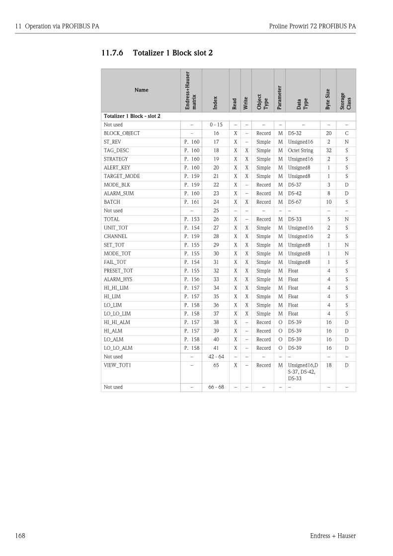
11 Operation via PROFIBUS PA Proline Prowirl 72 PROFIBUS PA
168 Endress + Hauser
11.7.6 Totalizer 1 Block slot 2
Name
En
dre
ss+
Hau
ser
matr
ix
Index
Read
Wri
te
Ob
ject
Type
Para
mete
r
Data
Type
Byte
Siz
e
Sto
rage
Cla
ss
Totalizer 1 Block - slot 2
Not used – 0 - 15 – – – – – – –
BLOCK_OBJECT – 16 X – Record M DS-32 20 C
ST_REV P. 160 17 X – Simple M Unsigned16 2 N
TAG_DESC P. 160 18 X X Simple M Octet String 32 S
STRATEGY P. 160 19 X X Simple M Unsigned16 2 S
ALERT_KEY P. 160 20 X X Simple M Unsigned8 1 S
TARGET_MODE P. 159 21 X X Simple M Unsigned8 1 S
MODE_BLK P. 159 22 X – Record M DS-37 3 D
ALARM_SUM P. 160 23 X – Record M DS-42 8 D
BATCH P. 161 24 X X Record M DS-67 10 S
Not used – 25 – – – – – – –
TOTAL P. 153 26 X – Record M DS-33 5 N
UNIT_TOT P. 154 27 X X Simple M Unsigned16 2 S
CHANNEL P. 159 28 X X Simple M Unsigned16 2 S
SET_TOT P. 155 29 X X Simple M Unsigned8 1 N
MODE_TOT P. 155 30 X X Simple M Unsigned8 1 N
FAIL_TOT P. 154 31 X X Simple M Unsigned8 1 S
PRESET_TOT P. 155 32 X X Simple M Float 4 S
ALARM_HYS P. 156 33 X X Simple M Float 4 S
HI_HI_LIM P. 157 34 X X Simple M Float 4 S
HI_LIM P. 157 35 X X Simple M Float 4 S
LO_LIM P. 158 36 X X Simple M Float 4 S
LO_LO_LIM P. 158 37 X X Simple M Float 4 S
HI_HI_ALM P. 157 38 X – Record O DS-39 16 D
HI_ALM P. 157 39 X – Record O DS-39 16 D
LO_ALM P. 158 40 X – Record O DS-39 16 D
LO_LO_ALM P. 158 41 X – Record O DS-39 16 D
Not used – 42 - 64 – – – – – – –
VIEW_TOT1 – 65 X – Record M Unsigned16,D
S-37, DS-42,
DS-33
18 D
Not used – 66 - 68 – – – – – – –
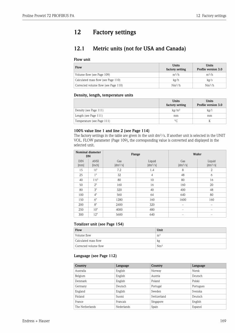
Proline Prowirl 72 PROFIBUS PA 12 Factory settings
Endress + Hauser 169
12 Factory settings
12.1 Metric units (not for USA and Canada)
Flow unit
Density, length, temperature units
100% value line 1 and line 2 (see Page 114)
The factory settings in the table are given in the unit dm³/s. If another unit is selected in the UNIT
VOL. FLOW parameter (Page 109), the corresponding value is converted and displayed in the
selected unit.
Totalizer unit (see Page 154)
Language (see Page 112)
FlowUnits
factory setting
Units
Profile version 3.0
Volume flow (see Page 109) m³/h m³/h
Calculated mass flow (see Page 110) kg/h kg/s
Corrected volume flow (see Page 110) Nm³/h Nm³/h
Units
factory setting
Units
Profile version 3.0
Density (see Page 111) kg/m³ kg/l
Length (see Page 111) mm mm
Temperature (see Page 111) °C K
Nominal diameter
DNFlange Wafer
DIN
[mm]
ANSI
[inch]
Gas
[dm³/s]
Liquid
[dm³/s]
Gas
[dm³/s]
Liquid
[dm³/s]
15 ½" 7.2 1.4 8 2
25 1" 32 4 48 6
40 1½" 80 10 80 16
50 2" 160 16 160 20
80 3" 320 40 400 48
100 4" 560 64 640 80
150 6" 1280 160 1600 160
200 8" 2400 320 – –
250 10" 4000 480 – –
300 12" 5600 640 – –
Flow Unit
Volume flow m³
Calculated mass flow kg
Corrected volume flow Nm³
Country Language Country Language
Australia English Norway Norsk
Belgium English Austria Deutsch
Denmark English Poland Polski
Germany Deutsch Portugal Portugues
England English Sweden Svenska
Finland Suomi Switzerland Deutsch
France Francais Singapore English
The Netherlands Nederlands Spain Espanol
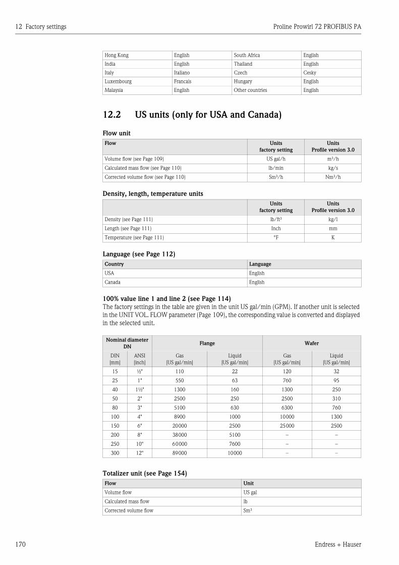
12 Factory settings Proline Prowirl 72 PROFIBUS PA
170 Endress + Hauser
12.2 US units (only for USA and Canada)
Flow unit
Density, length, temperature units
Language (see Page 112)
100% value line 1 and line 2 (see Page 114)
The factory settings in the table are given in the unit US gal/min (GPM). If another unit is selected
in the UNIT VOL. FLOW parameter (Page 109), the corresponding value is converted and displayed
in the selected unit.
Totalizer unit (see Page 154)
Hong Kong English South Africa English
India English Thailand English
Italy Italiano Czech Cesky
Luxembourg Francais Hungary English
Malaysia English Other countries English
Flow Units
factory setting
Units
Profile version 3.0
Volume flow (see Page 109) US gal/h m³/h
Calculated mass flow (see Page 110) lb/min kg/s
Corrected volume flow (see Page 110) Sm³/h Nm³/h
Units
factory setting
Units
Profile version 3.0
Density (see Page 111) lb/ft³ kg/l
Length (see Page 111) Inch mm
Temperature (see Page 111) °F K
Country Language
USA English
Canada English
Nominal diameter
DNFlange Wafer
DIN
[mm]
ANSI
[inch]
Gas
[US gal/min]
Liquid
[US gal/min]
Gas
[US gal/min]
Liquid
[US gal/min]
15 ½" 110 22 120 32
25 1" 550 63 760 95
40 1½" 1300 160 1300 250
50 2" 2500 250 2500 310
80 3" 5100 630 6300 760
100 4" 8900 1000 10000 1300
150 6" 20000 2500 25000 2500
200 8" 38000 5100 – –
250 10" 60000 7600 – –
300 12" 89000 10000 – –
Flow Unit
Volume flow US gal
Calculated mass flow lb
Corrected volume flow Sm³
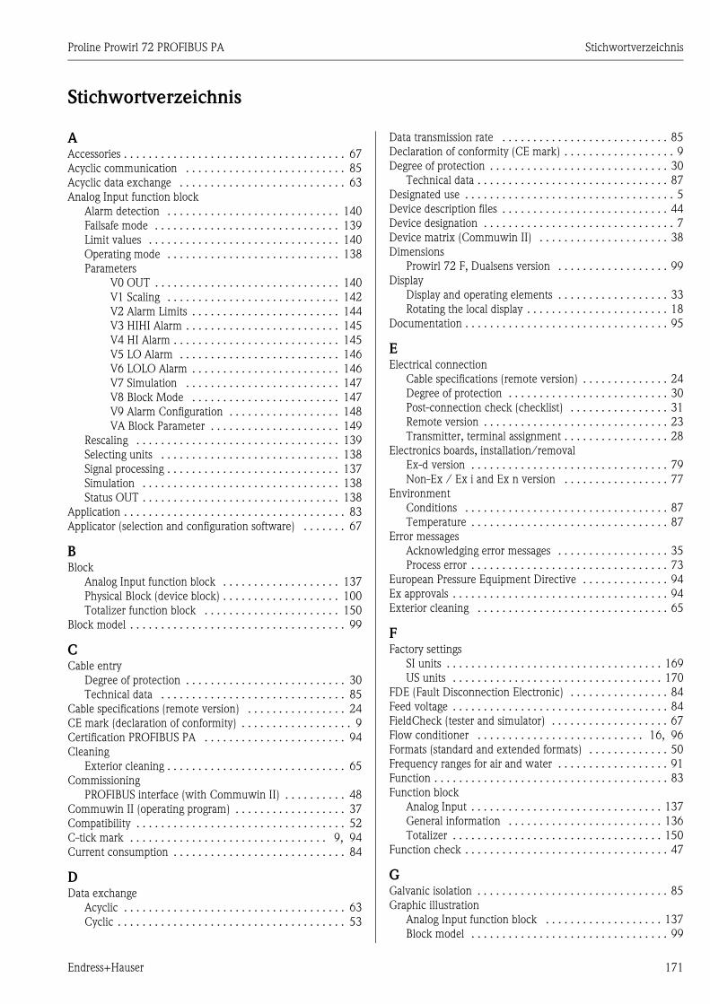
Proline Prowirl 72 PROFIBUS PA Stichwortverzeichnis
Endress+Hauser 171
Stichwortverzeichnis
AAccessories . . . . . . . . . . . . . . . . . . . . . . . . . . . . . . . . . . . . 67
Acyclic communication . . . . . . . . . . . . . . . . . . . . . . . . . . 85
Acyclic data exchange . . . . . . . . . . . . . . . . . . . . . . . . . . . 63
Analog Input function block
Alarm detection . . . . . . . . . . . . . . . . . . . . . . . . . . . . 140
Failsafe mode . . . . . . . . . . . . . . . . . . . . . . . . . . . . . . 139
Limit values . . . . . . . . . . . . . . . . . . . . . . . . . . . . . . . 140
Operating mode . . . . . . . . . . . . . . . . . . . . . . . . . . . . 138
Parameters
V0 OUT . . . . . . . . . . . . . . . . . . . . . . . . . . . . . . 140
V1 Scaling . . . . . . . . . . . . . . . . . . . . . . . . . . . . 142
V2 Alarm Limits . . . . . . . . . . . . . . . . . . . . . . . . 144
V3 HIHI Alarm . . . . . . . . . . . . . . . . . . . . . . . . . 145
V4 HI Alarm . . . . . . . . . . . . . . . . . . . . . . . . . . . 145
V5 LO Alarm . . . . . . . . . . . . . . . . . . . . . . . . . . 146
V6 LOLO Alarm . . . . . . . . . . . . . . . . . . . . . . . . 146
V7 Simulation . . . . . . . . . . . . . . . . . . . . . . . . . 147
V8 Block Mode . . . . . . . . . . . . . . . . . . . . . . . . 147
V9 Alarm Configuration . . . . . . . . . . . . . . . . . . 148
VA Block Parameter . . . . . . . . . . . . . . . . . . . . . 149
Rescaling . . . . . . . . . . . . . . . . . . . . . . . . . . . . . . . . . 139
Selecting units . . . . . . . . . . . . . . . . . . . . . . . . . . . . . 138
Signal processing . . . . . . . . . . . . . . . . . . . . . . . . . . . . 137
Simulation . . . . . . . . . . . . . . . . . . . . . . . . . . . . . . . . 138
Status OUT . . . . . . . . . . . . . . . . . . . . . . . . . . . . . . . . 138
Application . . . . . . . . . . . . . . . . . . . . . . . . . . . . . . . . . . . . 83
Applicator (selection and configuration software) . . . . . . . 67
BBlock
Analog Input function block . . . . . . . . . . . . . . . . . . . 137
Physical Block (device block) . . . . . . . . . . . . . . . . . . . 100
Totalizer function block . . . . . . . . . . . . . . . . . . . . . . 150
Block model . . . . . . . . . . . . . . . . . . . . . . . . . . . . . . . . . . . 99
CCable entry
Degree of protection . . . . . . . . . . . . . . . . . . . . . . . . . . 30
Technical data . . . . . . . . . . . . . . . . . . . . . . . . . . . . . . 85
Cable specifications (remote version) . . . . . . . . . . . . . . . . 24
CE mark (declaration of conformity) . . . . . . . . . . . . . . . . . . 9
Certification PROFIBUS PA . . . . . . . . . . . . . . . . . . . . . . . 94
Cleaning
Exterior cleaning . . . . . . . . . . . . . . . . . . . . . . . . . . . . . 65
Commissioning
PROFIBUS interface (with Commuwin II) . . . . . . . . . . 48
Commuwin II (operating program) . . . . . . . . . . . . . . . . . . 37
Compatibility . . . . . . . . . . . . . . . . . . . . . . . . . . . . . . . . . . 52
C-tick mark . . . . . . . . . . . . . . . . . . . . . . . . . . . . . . . . 9, 94
Current consumption . . . . . . . . . . . . . . . . . . . . . . . . . . . . 84
DData exchange
Acyclic . . . . . . . . . . . . . . . . . . . . . . . . . . . . . . . . . . . . 63
Cyclic . . . . . . . . . . . . . . . . . . . . . . . . . . . . . . . . . . . . . 53
Data transmission rate . . . . . . . . . . . . . . . . . . . . . . . . . . . 85
Declaration of conformity (CE mark) . . . . . . . . . . . . . . . . . . 9
Degree of protection . . . . . . . . . . . . . . . . . . . . . . . . . . . . . 30
Technical data . . . . . . . . . . . . . . . . . . . . . . . . . . . . . . . 87
Designated use . . . . . . . . . . . . . . . . . . . . . . . . . . . . . . . . . . 5
Device description files . . . . . . . . . . . . . . . . . . . . . . . . . . . 44
Device designation . . . . . . . . . . . . . . . . . . . . . . . . . . . . . . . 7
Device matrix (Commuwin II) . . . . . . . . . . . . . . . . . . . . . 38
Dimensions
Prowirl 72 F, Dualsens version . . . . . . . . . . . . . . . . . . 99
Display
Display and operating elements . . . . . . . . . . . . . . . . . . 33
Rotating the local display . . . . . . . . . . . . . . . . . . . . . . . 18
Documentation . . . . . . . . . . . . . . . . . . . . . . . . . . . . . . . . . 95
EElectrical connection
Cable specifications (remote version) . . . . . . . . . . . . . . 24
Degree of protection . . . . . . . . . . . . . . . . . . . . . . . . . . 30
Post-connection check (checklist) . . . . . . . . . . . . . . . . 31
Remote version . . . . . . . . . . . . . . . . . . . . . . . . . . . . . . 23
Transmitter, terminal assignment . . . . . . . . . . . . . . . . . 28
Electronics boards, installation/removal
Ex-d version . . . . . . . . . . . . . . . . . . . . . . . . . . . . . . . . 79
Non-Ex / Ex i and Ex n version . . . . . . . . . . . . . . . . . 77
Environment
Conditions . . . . . . . . . . . . . . . . . . . . . . . . . . . . . . . . . 87
Temperature . . . . . . . . . . . . . . . . . . . . . . . . . . . . . . . . 87
Error messages
Acknowledging error messages . . . . . . . . . . . . . . . . . . 35
Process error . . . . . . . . . . . . . . . . . . . . . . . . . . . . . . . . 73
European Pressure Equipment Directive . . . . . . . . . . . . . . 94
Ex approvals . . . . . . . . . . . . . . . . . . . . . . . . . . . . . . . . . . . 94
Exterior cleaning . . . . . . . . . . . . . . . . . . . . . . . . . . . . . . . 65
FFactory settings
SI units . . . . . . . . . . . . . . . . . . . . . . . . . . . . . . . . . . . 169
US units . . . . . . . . . . . . . . . . . . . . . . . . . . . . . . . . . . 170
FDE (Fault Disconnection Electronic) . . . . . . . . . . . . . . . . 84
Feed voltage . . . . . . . . . . . . . . . . . . . . . . . . . . . . . . . . . . . 84
FieldCheck (tester and simulator) . . . . . . . . . . . . . . . . . . . 67
Flow conditioner . . . . . . . . . . . . . . . . . . . . . . . . . . . 16, 96
Formats (standard and extended formats) . . . . . . . . . . . . . 50
Frequency ranges for air and water . . . . . . . . . . . . . . . . . . 91
Function . . . . . . . . . . . . . . . . . . . . . . . . . . . . . . . . . . . . . . 83
Function block
Analog Input . . . . . . . . . . . . . . . . . . . . . . . . . . . . . . . 137
General information . . . . . . . . . . . . . . . . . . . . . . . . . 136
Totalizer . . . . . . . . . . . . . . . . . . . . . . . . . . . . . . . . . . 150
Function check . . . . . . . . . . . . . . . . . . . . . . . . . . . . . . . . . 47
GGalvanic isolation . . . . . . . . . . . . . . . . . . . . . . . . . . . . . . . 85
Graphic illustration
Analog Input function block . . . . . . . . . . . . . . . . . . . 137
Block model . . . . . . . . . . . . . . . . . . . . . . . . . . . . . . . . 99
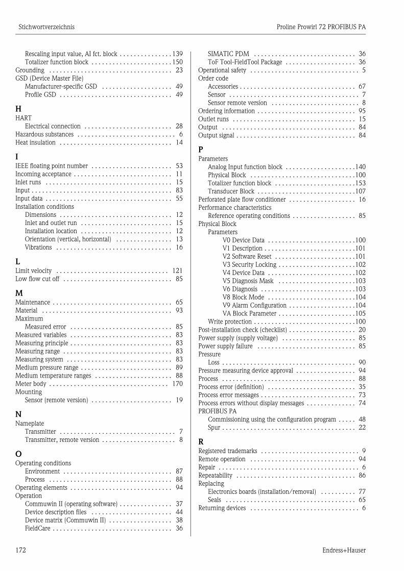
Stichwortverzeichnis Proline Prowirl 72 PROFIBUS PA
172 Endress+Hauser
Rescaling input value, AI fct. block . . . . . . . . . . . . . . . 139
Totalizer function block . . . . . . . . . . . . . . . . . . . . . . . 150
Grounding . . . . . . . . . . . . . . . . . . . . . . . . . . . . . . . . . . . 23
GSD (Device Master File)
Manufacturer-specific GSD . . . . . . . . . . . . . . . . . . . . 49
Profile GSD . . . . . . . . . . . . . . . . . . . . . . . . . . . . . . . . 49
HHART
Electrical connection . . . . . . . . . . . . . . . . . . . . . . . . . 28
Hazardous substances . . . . . . . . . . . . . . . . . . . . . . . . . . . . 6
Heat insulation . . . . . . . . . . . . . . . . . . . . . . . . . . . . . . . . 14
IIEEE floating point number . . . . . . . . . . . . . . . . . . . . . . . 53
Incoming acceptance . . . . . . . . . . . . . . . . . . . . . . . . . . . . 11
Inlet runs . . . . . . . . . . . . . . . . . . . . . . . . . . . . . . . . . . . . 15
Input . . . . . . . . . . . . . . . . . . . . . . . . . . . . . . . . . . . . . . . . 83
Input data . . . . . . . . . . . . . . . . . . . . . . . . . . . . . . . . . . . . 55
Installation conditions
Dimensions . . . . . . . . . . . . . . . . . . . . . . . . . . . . . . . . 12
Inlet and outlet run . . . . . . . . . . . . . . . . . . . . . . . . . . 15
Installation location . . . . . . . . . . . . . . . . . . . . . . . . . . 12
Orientation (vertical, horizontal) . . . . . . . . . . . . . . . . 13
Vibrations . . . . . . . . . . . . . . . . . . . . . . . . . . . . . . . . . 16
LLimit velocity . . . . . . . . . . . . . . . . . . . . . . . . . . . . . . . . 121
Low flow cut off . . . . . . . . . . . . . . . . . . . . . . . . . . . . . . . 85
MMaintenance . . . . . . . . . . . . . . . . . . . . . . . . . . . . . . . . . . 65
Material . . . . . . . . . . . . . . . . . . . . . . . . . . . . . . . . . . . . . 93
Maximum
Measured error . . . . . . . . . . . . . . . . . . . . . . . . . . . . . 85
Measured variables . . . . . . . . . . . . . . . . . . . . . . . . . . . . . 83
Measuring principle . . . . . . . . . . . . . . . . . . . . . . . . . . . . . 83
Measuring range . . . . . . . . . . . . . . . . . . . . . . . . . . . . . . . 83
Measuring system . . . . . . . . . . . . . . . . . . . . . . . . . . . . . . 83
Medium pressure range . . . . . . . . . . . . . . . . . . . . . . . . . . 89
Medium temperature ranges . . . . . . . . . . . . . . . . . . . . . . 88
Meter body . . . . . . . . . . . . . . . . . . . . . . . . . . . . . . . . . . 170
Mounting
Sensor (remote version) . . . . . . . . . . . . . . . . . . . . . . . 19
NNameplate
Transmitter . . . . . . . . . . . . . . . . . . . . . . . . . . . . . . . . . 7
Transmitter, remote version . . . . . . . . . . . . . . . . . . . . . 8
OOperating conditions
Environment . . . . . . . . . . . . . . . . . . . . . . . . . . . . . . . 87
Process . . . . . . . . . . . . . . . . . . . . . . . . . . . . . . . . . . . 88
Operating elements . . . . . . . . . . . . . . . . . . . . . . . . . . . . . 94
Operation
Commuwin II (operating software) . . . . . . . . . . . . . . . 37
Device description files . . . . . . . . . . . . . . . . . . . . . . . 44
Device matrix (Commuwin II) . . . . . . . . . . . . . . . . . . 38
FieldCare . . . . . . . . . . . . . . . . . . . . . . . . . . . . . . . . . . 36
SIMATIC PDM . . . . . . . . . . . . . . . . . . . . . . . . . . . . . 36
ToF Tool-FieldTool Package . . . . . . . . . . . . . . . . . . . . 36
Operational safety . . . . . . . . . . . . . . . . . . . . . . . . . . . . . . . 5
Order code
Accessories . . . . . . . . . . . . . . . . . . . . . . . . . . . . . . . . . 67
Sensor . . . . . . . . . . . . . . . . . . . . . . . . . . . . . . . . . . . . . 7
Sensor remote version . . . . . . . . . . . . . . . . . . . . . . . . . 8
Ordering information . . . . . . . . . . . . . . . . . . . . . . . . . . . . 95
Outlet runs . . . . . . . . . . . . . . . . . . . . . . . . . . . . . . . . . . . 15
Output . . . . . . . . . . . . . . . . . . . . . . . . . . . . . . . . . . . . . . 84
Output signal . . . . . . . . . . . . . . . . . . . . . . . . . . . . . . . . . . 84
PParameters
Analog Input function block . . . . . . . . . . . . . . . . . . . .140
Physical Block . . . . . . . . . . . . . . . . . . . . . . . . . . . . . .100
Totalizer function block . . . . . . . . . . . . . . . . . . . . . . .153
Transducer Block . . . . . . . . . . . . . . . . . . . . . . . . . . . .107
Perforated plate flow conditioner . . . . . . . . . . . . . . . . . . . 16
Performance characteristics
Reference operating conditions . . . . . . . . . . . . . . . . . . 85
Physical Block
Parameters
V0 Device Data . . . . . . . . . . . . . . . . . . . . . . . . .100
V1 Description . . . . . . . . . . . . . . . . . . . . . . . . . .101
V2 Software Reset . . . . . . . . . . . . . . . . . . . . . . .101
V3 Security Locking . . . . . . . . . . . . . . . . . . . . . .102
V4 Device Data . . . . . . . . . . . . . . . . . . . . . . . . .102
V5 Diagnosis Mask . . . . . . . . . . . . . . . . . . . . . .103
V6 Diagnosis . . . . . . . . . . . . . . . . . . . . . . . . . . .103
V8 Block Mode . . . . . . . . . . . . . . . . . . . . . . . . .104
V9 Alarm Configuration . . . . . . . . . . . . . . . . . . .104
VA Block Parameter . . . . . . . . . . . . . . . . . . . . . .105
Write protection . . . . . . . . . . . . . . . . . . . . . . . . . . . . .100
Post-installation check (checklist) . . . . . . . . . . . . . . . . . . . 20
Power supply (supply voltage) . . . . . . . . . . . . . . . . . . . . . 85
Power supply failure . . . . . . . . . . . . . . . . . . . . . . . . . . . . 85
Pressure
Loss . . . . . . . . . . . . . . . . . . . . . . . . . . . . . . . . . . . . . . 90
Pressure measuring device approval . . . . . . . . . . . . . . . . . 94
Process . . . . . . . . . . . . . . . . . . . . . . . . . . . . . . . . . . . . . . 88
Process error (definition) . . . . . . . . . . . . . . . . . . . . . . . . . 35
Process error messages . . . . . . . . . . . . . . . . . . . . . . . . . . . 73
Process errors without display messages . . . . . . . . . . . . . . 74
PROFIBUS PA
Commissioning using the configuration program . . . . . 48
Spur . . . . . . . . . . . . . . . . . . . . . . . . . . . . . . . . . . . . . . 22
RRegistered trademarks . . . . . . . . . . . . . . . . . . . . . . . . . . . . 9
Remote operation . . . . . . . . . . . . . . . . . . . . . . . . . . . . . . 94
Repair . . . . . . . . . . . . . . . . . . . . . . . . . . . . . . . . . . . . . . . . 6
Repeatability . . . . . . . . . . . . . . . . . . . . . . . . . . . . . . . . . . 86
Replacing
Electronics boards (installation/removal) . . . . . . . . . . 77
Seals . . . . . . . . . . . . . . . . . . . . . . . . . . . . . . . . . . . . . 65
Returning devices . . . . . . . . . . . . . . . . . . . . . . . . . . . . . . . 6
Proline Prowirl 72 PROFIBUS PA Stichwortverzeichnis
Endress+Hauser 173
SSafety icons . . . . . . . . . . . . . . . . . . . . . . . . . . . . . . . . . . . . 6
Safety instructions . . . . . . . . . . . . . . . . . . . . . . . . . . . . . . . 5
Seals
Replacing, replacement seals . . . . . . . . . . . . . . . . . . . . 65
Sensor transport . . . . . . . . . . . . . . . . . . . . . . . . . . . . . . . . 11
Service nameplate . . . . . . . . . . . . . . . . . . . . . . . . . . . . . . . 8
Shielding . . . . . . . . . . . . . . . . . . . . . . . . . . . . . . . . . . . . . 23
Signal coding . . . . . . . . . . . . . . . . . . . . . . . . . . . . . . . . . . 85
Signal on alarm . . . . . . . . . . . . . . . . . . . . . . . . . . . . . . . . 84
Slot/Index lists
AI1 Volume Flow Block slot 1 . . . . . . . . . . . . . . . . . . 167
Device management slot 1 . . . . . . . . . . . . . . . . . . . . 162
Physical Block slot 0 . . . . . . . . . . . . . . . . . . . . . . . . . 162
Totalizer 1 Block slot 2 . . . . . . . . . . . . . . . . . . . . . . . 168
Software
Versions (history) . . . . . . . . . . . . . . . . . . . . . . . . . . . . 81
Spare parts . . . . . . . . . . . . . . . . . . . . . . . . . . . . . . . . . . . . 76
Spur
PROFIBUS PA . . . . . . . . . . . . . . . . . . . . . . . . . . . . . . . 22
Standards and guidelines . . . . . . . . . . . . . . . . . . . . . . . . . 95
Storage conditions . . . . . . . . . . . . . . . . . . . . . . . . . . . . . . 11
Storage temperature . . . . . . . . . . . . . . . . . . . . . . . . . . . . . 87
Supply voltage (power supply) . . . . . . . . . . . . . . . . . . . . . 85
System design . . . . . . . . . . . . . . . . . . . . . . . . . . . . . . . . . 83
System error
System error messages . . . . . . . . . . . . . . . . . . . . . . . . 71
System error (definition) . . . . . . . . . . . . . . . . . . . . . . . . . . 35
System integration (commissioning) . . . . . . . . . . . . . . . . . 49
TTechnical data at a glance . . . . . . . . . . . . . . . . . . . . . . . . . 83
Temperature ranges
Ambient temperature range . . . . . . . . . . . . . . . . . . . . 87
Medium temperature . . . . . . . . . . . . . . . . . . . . . . . . . 88
Storage temperature . . . . . . . . . . . . . . . . . . . . . . . . . . 87
ToF Tool-FieldTool Package . . . . . . . . . . . . . . . . . . . . . . . 36
Totalizer
Alarm detection . . . . . . . . . . . . . . . . . . . . . . . . . . . . 153
Failsafe mode FAIL TOT . . . . . . . . . . . . . . . . . . . . . . 151
Initial setting, SET TOT . . . . . . . . . . . . . . . . . . . . . . . 152
Limit values . . . . . . . . . . . . . . . . . . . . . . . . . . . . . . . 152
Operating mode . . . . . . . . . . . . . . . . . . . . . . . . . . . . 150
Parameters
V0 Total . . . . . . . . . . . . . . . . . . . . . . . . . . . . . . 153
V1 Configuration . . . . . . . . . . . . . . . . . . . . . . . 154
V2 Alarm Limits . . . . . . . . . . . . . . . . . . . . . . . . 156
V3 HIHI Alarm . . . . . . . . . . . . . . . . . . . . . . . . . 157
V4 HI Alarm . . . . . . . . . . . . . . . . . . . . . . . . . . . 157
V5 LO Alarm . . . . . . . . . . . . . . . . . . . . . . . . . . 158
V6 LOLO Alarm . . . . . . . . . . . . . . . . . . . . . . . . 158
V8 Block Mode . . . . . . . . . . . . . . . . . . . . . . . . 159
V9 Alarm Configuration . . . . . . . . . . . . . . . . . . 160
VA Block Parameter . . . . . . . . . . . . . . . . . . . . . 160
Status output value . . . . . . . . . . . . . . . . . . . . . . . . . . 151
Totalizer mode, MODE TOT . . . . . . . . . . . . . . . . . . . 151
UNIT TOT unit . . . . . . . . . . . . . . . . . . . . . . . . . . . . . 151
Totalizer, controls . . . . . . . . . . . . . . . . . . . . . . . . . . . . . . 56
Transducer Block . . . . . . . . . . . . . . . . . . . . . . . . . . . . . . 105
Access . . . . . . . . . . . . . . . . . . . . . . . . . . . . . . . . . . . . 106
Alarm detection . . . . . . . . . . . . . . . . . . . . . . . . . . . . 106
Device matrix parameters
V0 Measuring Values . . . . . . . . . . . . . . . . . . . . 107
V1 System Units . . . . . . . . . . . . . . . . . . . . . . . . 109
V2 Operation . . . . . . . . . . . . . . . . . . . . . . . . . . 112
V3 User interface . . . . . . . . . . . . . . . . . . . . . . . 113
V4 Process Parameters . . . . . . . . . . . . . . . . . . . 116
V5 System Parameters . . . . . . . . . . . . . . . . . . . 122
V6 PROFIBUS DP/PA . . . . . . . . . . . . . . . . . . . . 123
V7 PROFIBUS info . . . . . . . . . . . . . . . . . . . . . . 125
V9 Sensor Data . . . . . . . . . . . . . . . . . . . . . . . . . 127
VA Measuring Point . . . . . . . . . . . . . . . . . . . . . 129
Output variables . . . . . . . . . . . . . . . . . . . . . . . . . . . . 106
Parameter using profile parameters
V1 Volume Flow . . . . . . . . . . . . . . . . . . . . . . . . 133
V5 Vortex . . . . . . . . . . . . . . . . . . . . . . . . . . . . . 133
V7 System Parameters . . . . . . . . . . . . . . . . . . . 134
V8 Block Mode . . . . . . . . . . . . . . . . . . . . . . . . . 134
V9 Alarm Configuration . . . . . . . . . . . . . . . . . . 135
VA Block Parameter . . . . . . . . . . . . . . . . . . . . . 136
Service&Analysis parameters
V0 Supervision . . . . . . . . . . . . . . . . . . . . . . . . . 130
V4 Simulation . . . . . . . . . . . . . . . . . . . . . . . . . . 131
V6 Sensor Version . . . . . . . . . . . . . . . . . . . . . . . 132
V7 Amplifier Version . . . . . . . . . . . . . . . . . . . . . 132
V8 Info I/O module . . . . . . . . . . . . . . . . . . . . . 132
VA Measuring Point . . . . . . . . . . . . . . . . . . . . . 132
Signal processing . . . . . . . . . . . . . . . . . . . . . . . . . . . . 106
Transmitter
Rotating the housing . . . . . . . . . . . . . . . . . . . . . . . . . . 18
Troubleshooting . . . . . . . . . . . . . . . . . . . . . . . . . . . . . . . . 69
Types of error (system and process errors) . . . . . . . . . . . . . 35
VVelocity warning . . . . . . . . . . . . . . . . . . . . . . . . . . . . . . 121
Vibrations . . . . . . . . . . . . . . . . . . . . . . . . . . . . . . . . . . . . . 16
WWarning
Velocity . . . . . . . . . . . . . . . . . . . . . . . . . . . . . . . . . . 121
Weight
Prowirl 72 F, Dualsens version . . . . . . . . . . . . . . . . . . 99

Stichwortverzeichnis Proline Prowirl 72 PROFIBUS PA
174 Endress+Hauser


www.endress.com/worldwide
BA085D/06/en/01.07
71040780
FM+SGML 6.0