PROwatt TM 250 12V/24V POWER INVERTER OWNER’S …4… · PROwatt TM 250 12V/24V POWER INVERTER...
25
PROwatt TM 250 12V/24V POWER INVERTER OWNER’S MANUAL STATPOWER TECHNOLOGIES CORPORATION 7725 Lougheed Highway Burnaby, BC, Canada V5A 4V8 Tel: (604) 420-1585 Fax: (604) 420-1591 Internet: http://www.statpower.com
Transcript of PROwatt TM 250 12V/24V POWER INVERTER OWNER’S …4… · PROwatt TM 250 12V/24V POWER INVERTER...

PROwatt TM 250 12V/24V POWER INVERTER
OWNER’S MANUAL
STATPOWER TECHNOLOGIES CORPORATION 7725 Lougheed Highway
Burnaby, BC, Canada V5A 4V8
Tel: (604) 420-1585 Fax: (604) 420-1591
Internet: http://www.statpower.com
PROwatt is a trademark of Statpower Technologies Corporation. Copyright © 1996, 1997 Statpower Technologies Corporation. All rights reserved.
Table of Contents
1. Introduction......................................................................................1
2. How Your PROwatt 250 Works .....................................................1 2.1 Principle of operation .............................................................1 2.2 PROwatt 250 output waveform ..............................................2
3. Installation.......................................................................................4 3.1 Power source ..........................................................................4 3.2 Connecting to power source ...................................................5 3.3 Connection to load................................................................10 3.4 Placement of inverter............................................................11
4. Operating Tips ...............................................................................12 4.1 Rated versus actual current draw of equipment ....................12 4.2 Battery operating time .........................................................13
5. Troubleshooting .............................................................................14 5.1 Common problems ...............................................................14 5.2 Troubleshooting guide..........................................................15
6. Warranty ........................................................................................18 6.1 Warranty terms .....................................................................18 6.2 To obtain warranty service ...................................................19
7. Other Products From Statpower Technologies ...........................22
8. Product Specifications ...................................................................23

1
1. Introduction
Your new PROwatt 250 power inverter is a member of the most advanced line of DC to AC inverters available today. It will give you years of dependable service in your vehicle, boat, RV, or remote home.
To get the most out of your PROwatt 250, it must be installed and used properly. Please read the installation and operating instructions in this manual carefully before installing and using your PROwatt 250. Pay special attention to the CAUTION and WARNING statements in this manual and on the PROwatt 250. CAUTION statements identify conditions or practices which could result in damage to your PROwatt 250 or to other equip-ment. WARNING statements identify conditions or practices that could result in personal injury or loss of life.
2. How Your PROwatt 250 Works
An inverter is an electronic device that converts low voltage DC (direct current) electricity from a battery or other power source to standard 115 volts AC (alternating current) household power. In designing the PROwatt 250, Statpower has used design tech-niques previously employed in computer power supplies to give you an inverter that is smaller, lighter, and easier to use than any other inverter with a similar power rating.
2.1 Principle of operation
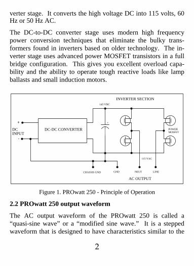
The PROwatt 250 converts power in two stages. The first stage is a DC-to-DC converter that raises the low voltage DC at the inverter input to 145 volts DC. The second stage is the actual in-
2
verter stage. It converts the high voltage DC into 115 volts, 60 Hz or 50 Hz AC.
The DC-to-DC converter stage uses modern high frequency power conversion techniques that eliminate the bulky trans-formers found in inverters based on older technology. The in-verter stage uses advanced power MOSFET transistors in a full bridge configuration. This gives you excellent overload capa-bility and the ability to operate tough reactive loads like lamp ballasts and small induction motors.
DC-DC CONVERTERDCINPUT
+
-
CHASSIS GND GND NEUT LINE
POWERMOSFET
115 VAC
145 VDC
INVERTER SECTION
AC OUTPUT
+
Figure 1. PROwatt 250 - Principle of Operation
2.2 PROwatt 250 output waveform
The AC output waveform of the PROwatt 250 is called a “quasi-sine wave” or a “modified sine wave.” It is a stepped waveform that is designed to have characteristics similar to the

3
sine wave shape of utility power. A waveform of this type is suitable for most AC loads, including linear and switching power supplies used in electronic equipment, transformers, and motors. This waveform is much superior to the square wave produced by many other DC to AC inverters.
The modified sine wave produced by the PROwatt 250 is de-signed to have a RMS (root mean square) voltage of 115 volts, the same as standard household power. Most AC voltmeters (both digital and analog) are sensitive to the average value of the waveform rather than the RMS value. They are calibrated for RMS voltage under the assumption that the waveform meas-ured will be a pure sine wave. These meters will not read the RMS voltage of a modified sine wave correctly. They will read about 2 to 20 volts low (i.e. about 100V) when measuring the output of the PROwatt 250. For accurate measurement of the output voltage of the PROwatt 250, a true RMS reading volt-meter such as a Fluke 87, Fluke 8060A, Beckman 4410, or Triplett 4200 must be used.

4
145 Volts peak
115 Volts RMS
8.3 milliseconds
Figure 2. PROwatt 250 Modified Sine Wave
3. Installation
3.1 Power source
For optimum performance, the power source must provide be-tween 11 and 14.5 volts (22-30 volts for PROwatt 250/24V) and must be able to supply sufficient current to operate the load. The power source may be a battery or a well-regulated DC power supply. As a rough guideline, divide the power con-sumption of the load (in watts) by 10 (by 20 for PROwatt 250/24V) to obtain the current (in amperes) the power source must deliver.
Example: Load is rated at 120 watts. Power source must be able to deliver:
120 ÷ 10 = 12 amps (or 6 amps for PROwatt 250/24V)

5
CAUTION: The PROwatt 250 must be connected only to bat-teries with a nominal output voltage of 12 volts (24 volts for PROwatt 250/24V). The PROwatt 250 will not operate from a 6 volt battery (12 volt for PROwatt 250/24V) and will be dam-aged if connected to a voltage source above 16 volts (32 volts for PROwatt 250/24V).
3.2 Connecting to power source
The PROwatt 250 is equipped with a cigarette lighter plug for connection to the power source. The tip of the plug is positive and the side contact is negative. Connect the plug to the ciga-rette lighter socket in a vehicle or to the cigarette lighter socket on a battery pack.
CAUTION: CONNECT THE 12V PROwatt 250 DIRECTLY TO POWER SOURCE WHEN OPERATING ABOVE 150 WATTS
The cigarette lighter plug is suitable for operating the 12V in-verter at power outputs of up to 150 watts. If the PROwatt 250/12V power inverter is to be used for extended periods at power levels above 150 watts, direct connection to the power source is recommended. Removal of the lighter plug is not nec-essary for the PROwatt 250/24V.
To make a direct connection, follow these steps:
1) Cut the cigarette lighter plug from the PROwatt 250 cord. One conductor on the PROwatt cord is marked with a red or white stripe. This is the positive conductor.
6
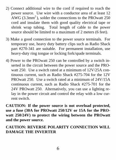
2) Connect additional wire to the cord if required to reach the power source. Use wire with a conductor area of at least 12 AWG (3.3mm2 ), solder the connections to the PROwatt 250 cord and insulate them with good quality electrical tape or shrink wrap tubing. Total length of cable to the power source should be limited to a maximum of 2 meters (6 feet).
3) Make a good connection to the power source terminals. For temporary use, heavy duty battery clips such as Radio Shack part #270-341 are suitable. For permanent installation, use heavy-duty ring tongue or locking fork/spade terminals.
4) Power to the PROwatt 250 can be controlled by a switch in-serted in the circuit between the power source and the PRO-watt 250. Use a switch rated at a minimum of 12V/25A con-tinuous current, such as Radio Shack #275-704 for the 12V PROwatt 250. Use a switch rated at a minimum of 24V/15A continuous current, such as Radio Shack #275-701 for the 24V PROwatt 250. Alternatively, you can use a lighting re-lay in the power circuit and control the relay with a low cur-rent switch.
CAUTION: If the power source is not overload protected, use a fuse (30A for PROwatt 250/12V or 15A for the PRO-watt 250/24V) to protect the wiring between the PROwatt and the power source.
CAUTION: REVERSE POLARITY CONNECTION WILL DAMAGE THE INVERTER
7
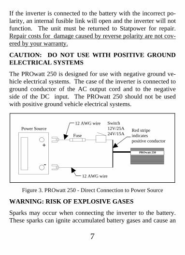
If the inverter is connected to the battery with the incorrect po-larity, an internal fusible link will open and the inverter will not function. The unit must be returned to Statpower for repair. Repair costs for damage caused by reverse polarity are not cov-ered by your warranty.
CAUTION: DO NOT USE WITH POSITIVE GROUND ELECTRICAL SYSTEMS
The PROwatt 250 is designed for use with negative ground ve-hicle electrical systems. The case of the inverter is connected to ground conductor of the AC output cord and to the negative side of the DC input. The PROwatt 250 should not be used with positive ground vehicle electrical systems.
12 AWG wire
12 AWG wire Power Source
-
+
Red stripe indicates positive conductor
Switch 12V/25A24V/15AFuse
PROwatt 250
Figure 3. PROwatt 250 - Direct Connection to Power Source
WARNING: RISK OF EXPLOSIVE GASES
Sparks may occur when connecting the inverter to the battery. These sparks can ignite accumulated battery gases and cause an
8
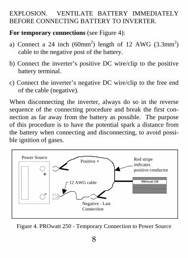
EXPLOSION. VENTILATE BATTERY IMMEDIATELY BEFORE CONNECTING BATTERY TO INVERTER.
For temporary connections (see Figure 4):
a) Connect a 24 inch (60mm2) length of 12 AWG (3.3mm2) cable to the negative post of the battery.
b) Connect the inverter’s positive DC wire/clip to the positive battery terminal.
c) Connect the inverter’s negative DC wire/clip to the free end of the cable (negative).
When disconnecting the inverter, always do so in the reverse sequence of the connecting procedure and break the first con-nection as far away from the battery as possible. The purpose of this procedure is to have the potential spark a distance from the battery when connecting and disconnecting, to avoid possi-ble ignition of gases.
Red stripe indicates positive conductor
-
+
Power Source Positive +
12 AWG cable
Negative - Last Connection
PROwatt 250
Figure 4. PROwatt 250 - Temporary Connection to Power Source

9
TO SERVICE PERSONNEL: The PROwatt 250 contains a replaceable 30 amp (15 amp for PROwatt 250/24V) automotive blade type fuse, Littelfuse part #275-030 (Littelfuse part #275-015 for PROwatt 250/24V). These fuses are available at auto-motive parts suppliers and many electronic components suppli-ers.
WARNING: Capacitors in the PROwatt 250 retain dangerous high voltages even after the inverter is disconnected from the power source.
To replace the fuses, follow these steps:
1) Disconnect the 12/24 volt plug.
2) Wait 60 seconds.
3) Remove the two screws from the end plate where the DC cord enters the inverter. Turn the end plate to expose the printed circuit board. The fuses are located at the edge of the circuit board and may be removed with a pair of needle-nose pliers. Check the fuses and replace if they have opened.
4) Reassemble the inverter and test it. If it does not function, check the fuses again, following the procedure given above. If the fuses have opened again, the inverter is damaged and must be returned for service.
10
3.3 Connection to load
The PROwatt 250 is equipped with a standard AC receptacle. Plug the cord from the equipment you wish to operate into this receptacle.
CAUTION: DO NOT CONNECT TO AC DISTRIBUTION WIRING
The PROwatt 250 is designed to be directly connected to stan-dard electrical and electronic equipment in the fashion described above. Do not connect the PROwatt 250 to household or RV AC distribution wiring. Do not connect the PROwatt 250 to any AC load circuit in which the neutral conductor is connected to ground (earth) or to the negative of the DC (battery) source.
CAUTION: RECHARGEABLE APPLIANCES
Certain rechargers for small nickel cadmium batteries can be damaged if connected to the PROwatt 250. Two particu-lar types of equipment are prone to this problem:
1) Small battery operated appliances such as flashlights, razors, and night-lights that can be plugged directly into an AC re-ceptacle to recharge.
2) Certain battery chargers for battery packs used in hand power tools. These chargers will have a warning label stating that dangerous voltages are present at the battery terminals.
Do NOT use the PROwatt 250 with the above equipment.

11
This problem does not occur with the vast majority of battery operated equipment. Most of this equipment uses a separate charger or transformer that is plugged into the AC receptacle and produces a low voltage output. If the label on the AC adapter or charger states that the adapter or charger produces a low voltage AC or DC output (less than 30 volts), the PROwatt 250 will have no trouble powering this charger or adapter safely.
3.4 Placement of inverter
For best operating results, the inverter should be placed on a flat surface, such as the floor or seat of a vehicle. Approximately 0.6 m (2 feet) of cord has been provided for this purpose. The inverter should only be used in locations that meet the following requirements:
a) Dry - do not allow water to drip or splash on the PROwatt 250.
b) Cool - ambient air temperature should be between 0º C and 40º C - ideally between 15º C and 25º C. Do not place the inverter on or near a heating vent or any piece of equipment which is generating heat above room temperature. Do not place the inverter in direct sunlight if avoidable.
c) Ventilated - allow at least one inch of clearance around the PROwatt 250 for air flow. Do not place items on or over the inverter during operation. Make sure that air is allowed to circulate freely around the unit. A fan is helpful in the case

12
where the inverter is operating at maximum power output for extended periods.
The unit will shut down if the internal temperature exceeds 90ºC. It will restart once it cools off.
CAUTION: PROwatt 250 CASE GETS HOT
The case of the PROwatt 250 acts as a heat sink, dispersing in-ternally generated heat. When the PROwatt 250 is operating at high power levels (above 100 watts) for extended periods, the case will get hot. Surface temperatures may approach 60º C (140º F) on some parts of the case. When operating at high power levels, do not place the PROwatt 250 on or near materials that may be affected by these temperatures. Use caution when handling the PROwatt 250 if it is operating at high power lev-els.
d) Safe - do not use the PROwatt 250 near flammable materials or in any location which may accumulate flammable fumes or gases.
4. Operating Tips
4.1 Rated versus actual current draw of equipment
Manufacturers of electrical and electronic equipment often over rate the current drawn by their products. If a piece of electrical or electronic equipment is rated at 300 watts or less, the PRO-watt 250 will probably operate it. The inverter has overload protection, so it is safe to try it with equipment rated at 300

13
watts or more. The inverter will shut down if it is overloaded, and will restart once the overload is removed.
The PROwatt 250 will NOT operate appliances that produce heat, such as hair dryers, microwave ovens, and toasters.
4.2 Battery operating time
With a typical vehicle battery, a minimum operating time of 5 hours can be expected. In most cases, 5 to 10 hours of operat-ing time is achievable. Statpower recommends that the operator start the vehicle every 2 - 3 hours to recharge the battery. Peri-odically charging the battery will prevent any unexpected shut-downs of the equipment and will ensure that there is always sufficient battery capacity to start the vehicle engine.
The inverter may be used either while the engine is running or turned off. However, the inverter may not operate while the engine is starting since the battery voltage can drop substan-tially during cranking.
The PROwatt 250 draws less than 0.1 ampere from the battery when it is not supplying power to a load. In most cases the PROwatt 250 can be left connected to the battery when it is not in use since it draws so little current. If the vehicle will not be used for several days, disconnect the PROwatt 250 from the bat-tery.
CAUTION: LOW BATTERY ALARM

14
An alarm will sound when the voltage from the battery drops to 10.7 volts (21.5V for PROwatt 250/24V). This indicates that the battery requires charging. The user should stop operations at this time since the PROwatt 250 will shut down automatically shortly afterwards.
If the low battery alarm sounds when the battery is fully charged, follow the steps for remedying lack of power output in section 5.2 (Troubleshooting Guide) of the manual. The alarm will sound when the inverter is overloaded, in thermal shut-down, or if there is an excessive voltage drop between the bat-tery and inverter.
5. Troubleshooting
5.1 Common problems
Buzz in audio systems Some inexpensive stereo systems and “boom boxes” will emit a buzzing sound from their loudspeak-ers when operated from the PROwatt 250. This is because the power supply in the device does not adequately filter the modi-fied sine wave produced by the PROwatt 250. The only solu-tion is to use a sound system that incorporates a higher quality power supply.
Television interference The PROwatt 250 is shielded and fil-tered to minimize interference with TV signals. In some cases, particularly with weak TV signals, some interference may still be visible. Try the following corrective measures:

15
a) Position the PROwatt 250 as far as possible from the televi-sion, the antenna and the antenna cables. Use an extension cord to move the PROwatt 250 away from the television.
b) Adjust the orientation of the PROwatt 250, the antenna ca-bles, and the TV power cord to minimize interference.
c) Make sure that the antenna feeding the television provides an adequate (“snow free”) signal and that high quality, shielded antenna cable is used.
These measures will usually improve the situation. If they do not, you may wish to try a different make of TV set or an an-tenna that can provide a stronger signal. Experience has shown that different models of TV sets vary in their susceptibility to interference.
5.2 Troubleshooting guide
Problem: Lack of power output
Possible cause Suggested remedy
Poor contact with lighter. Clean lighter thoroughly. Replace outlet if necessary. Spread contacts on lighter plug.
Automotive electrical Turn ignition key to access- system requires ignition ory position. to be on.

16
Cigarette lighter circuit fuse Check vehicle fuses, replace open (blown). damaged fuse.
Poor connection or Repair connections and use inadequate wiring between heavier gauge wire (3.3mm2 battery and cigarette lighter. or 12 AWG is sug-gested).
Battery voltage below 10 Recharge or replace battery. volts (20 volts for PROwatt 250/24V).

17
Load draws too much Reduce load to 300 watts power. max.
Inverter in thermal Allow inverter to cool. En-shutdown. sure there is adequate vent- ilation. Ensure that load is no more than 225 watts for continuous operation.
Fusible link in inverter Return for service. Ensure is open. that inverter is connected to power source with correct voltage and polarity.
Problem: Low output voltage
Possible cause Suggested remedy
Using average reading volt- Use true RMS reading me-meter. ter. See section 2.2 of man- ual.
Inverter is overloaded. Reduce load to 250 watts maximum to maintain regulation.
Power source voltage Keep power source voltage below 11.5 volts (23 volts above 11.5 volts (23 volts for PROwatt 250/24V). for PROwatt 250/24V) to maintain regulation.

18
6 Warranty
6.1 Warranty terms
Statpower manufactures its hardware products from parts and components that are new or equivalent to new in accordance with industry-standard practices. Statpower warrants the PRO-watt 250 to be free from defects in workmanship or materials for 12 months from the date of purchase. During this period, Statpower will, at its option, repair or replace the defective product free of charge. This warranty will be considered void if the unit has suffered any physical damage or alteration, either internally or externally, and does not cover damage arising from improper use, attempting to operate products with excessive power consumption requirements, or from use in an unsuitable environment. This warranty will not apply where the product has been misused, neglected, improperly installed, or repaired by anyone other than Statpower. In order to qualify for the war-ranty, the product must not be disassembled or modified without prior authorization by Statpower.
Repair or replacement are your sole remedies and Statpower shall not be liable for damages, whether direct, incidental, spe-cial, or consequential, even though caused by negligence or fault.
Statpower owns all parts removed from repaired products. Stat-power uses new and reconditioned parts made by various manu-facturers in performing warranty repairs and building replace-ment products. If Statpower repairs or replaces a product, its warranty term is not extended.

19
THIS IS STATPOWER’S ONLY WARRANTY, AND THE COMPANY MAKES NO WARRANTIES, EXPRESS OR IMPLIED, INCLUDING WARRANTIES OF MERCHANTABILITY AND FITNESS FOR A PARTICULAR PURPOSE.
6.2 To obtain warranty service
If your PROwatt 250 requires service, please return it to your place of purchase. If you are unable to contact your merchant, or the merchant is unable to provide service, contact the Stat-power Customer Service Department directly.
BY PHONE: (604) 420-1585 BY FAX: (604) 420-1591 BY MAIL: Statpower Technologies Corporation Customer Service Dept. 7725 Lougheed Highway Burnaby, BC V5A 4V8 CANADA BY EMAIL: [email protected]
In order to assist you, the customer service representative will need the following information:
- a description of the problem, - serial number of the unit, - name and address of the dealer where you purchased the unit, - date of purchase.

20
If your PROwatt 250 requires service, the customer service rep-resentative will issue you a RETURN AUTHORIZATION NUMBER.
DO NOT RETURN ANY PRODUCT TO STATPOWER WITHOUT A RETURN AUTHORIZATION NUMBER.
If you are returning a PROwatt 250 from Canada, follow this procedure:
1. Obtain a Return Authorization Number from Statpower.
2. Package the unit safely, preferably using the original box and packing materials. Include the Return Authorization Number, a return address where the repaired unit can be shipped, a contact telephone number, and a brief description of the prob-lem.
3. Ship the unit to the following address, freight prepaid:
Statpower Technologies Corporation 7725 Lougheed Hwy. Burnaby, BC V5A 4V8

21
If you are returning a PROwatt 250 from USA, follow the pro-cedure above but ship the unit, freight prepaid, to the following address:
Statpower Technologies Corporation c/o International Parcel Service Warehouse #8 - 14th Street Blaine, WA 98230
If you are returning a PROwatt 250 from outside North America please contact the local Statpower dealer in your country.

22
7 Other Products From Statpower Technologies
Statpower Technologies develops, manufactures and markets power electronic products. Our goal is to offer you top quality products that convert and control electric power. We specialize in DC to AC inverters, battery packs, battery chargers, backup power supplies and other products associated with mobile or power backup applications.
PROwattTM150 Inverter A medium power version of the PROwatt 250, the PROwatt 150 delivers 150 watts of AC power yet small enough to hold in the palm of a hand. Ideal for lights, small screen TV sets, laptop computers and other applications.
PROwattTM800 Inverter, PROwattTM1500 Inverter, and PROwattTM2500 Inverter Compact 800, 1500, and 2500 watt DC to AC inverters designed for permanent installation in a boat, vehicle, or remote home. These inverters operate power tools, kitchen appliances, and a wide range of other electrical and electronic batteries.
TRUECHARGETM Battery Chargers Microprocessor con-trolled, multi-step automatic battery chargers. Ideal for deep cycle marine, RV and industrial batteries.
For more information on these products, and other soon to be introduced products, contact your dealer or Statpower directly.

23
8 Product Specifications
Output power continuous 225 Watts 10 minutes 350 Watts surge 500 Watts Output voltage 115 VAC RMS± 5% Output frequency 60 Hz ± 0.01% Output waveform modified sinewave Input voltage
10 - 15 VDC (for PROwatt 250/24V 20 - 30 VDC)
Efficiency 90% No-load current draw <0.07 Amps Low battery alarm 10.7 Volts
(for PROwatt 250/24V 21.5 Volts) Low battery shutdown 10 Volts
(for PROwatt 250/24V 20 Volts) Dimensions 1.5 x 4.5 x 6 inches Weight 28 oz (0.87 kg)
* Specifications subject to change without notification.
Drawing No. 440-0166 Rev 3 Filename: 445-0007.doc