Provisioning Reconfigurable Optical Add/Drop Cards · Wavelength (nm) Frequency (THz) Channel...
52
Provisioning Reconfigurable Optical Add/Drop Cards This chapter describes the line cards deployed in reconfigurable optical add/drop (ROADM) networks. These cards perform mesh topology functions. For card safety and compliance information, refer to the Regulatory Compliance and Safety Information for Cisco ONS Platforms document. The cards described in this chapter are supported on the Cisco ONS 15454, Cisco ONS 15454 M6, Cisco ONS 15454 M2 platforms, unless noted otherwise. Note Unless otherwise specified, “ONS 15454” refers to both ANSI and ETSI shelf assemblies. Note • Card Compatibility, on page 1 • Channel Allocation Plans, on page 3 • Safety Labels, on page 6 • 32WSS and 32WSS-L Cards, on page 6 • 32DMX and 32DMX-L Cards, on page 11 • 40-DMX-C and 40-DMX-CE Card, on page 13 • 40-MUX-C Card, on page 18 • 40-WSS-C and 40-WSS-CE Card, on page 20 • 40-WXC-C Card, on page 23 • 80-WXC-C Card, on page 26 • 16-WXC-FS Card, on page 34 • Single Module ROADM (SMR-C) Cards, on page 38 • MMU Card, on page 51 Card Compatibility The following table lists the Cisco Transport Controller (CTC) software compatibility for the ROADM cards. Provisioning Reconfigurable Optical Add/Drop Cards 1
Transcript of Provisioning Reconfigurable Optical Add/Drop Cards · Wavelength (nm) Frequency (THz) Channel...
Provisioning Reconfigurable Optical Add/DropCards
This chapter describes the line cards deployed in reconfigurable optical add/drop (ROADM) networks. Thesecards perform mesh topology functions.
For card safety and compliance information, refer to the Regulatory Compliance and Safety Information forCisco ONS Platforms document.
The cards described in this chapter are supported on the Cisco ONS 15454, Cisco ONS 15454 M6,Cisco ONS 15454 M2 platforms, unless noted otherwise.
Note
Unless otherwise specified, “ONS 15454” refers to both ANSI and ETSI shelf assemblies.Note
• Card Compatibility, on page 1• Channel Allocation Plans, on page 3• Safety Labels, on page 6• 32WSS and 32WSS-L Cards, on page 6• 32DMX and 32DMX-L Cards, on page 11• 40-DMX-C and 40-DMX-CE Card, on page 13• 40-MUX-C Card, on page 18• 40-WSS-C and 40-WSS-CE Card, on page 20• 40-WXC-C Card, on page 23• 80-WXC-C Card, on page 26• 16-WXC-FS Card, on page 34• Single Module ROADM (SMR-C) Cards, on page 38• MMU Card, on page 51
Card CompatibilityThe following table lists the Cisco Transport Controller (CTC) software compatibility for the ROADM cards.
Provisioning Reconfigurable Optical Add/Drop Cards1
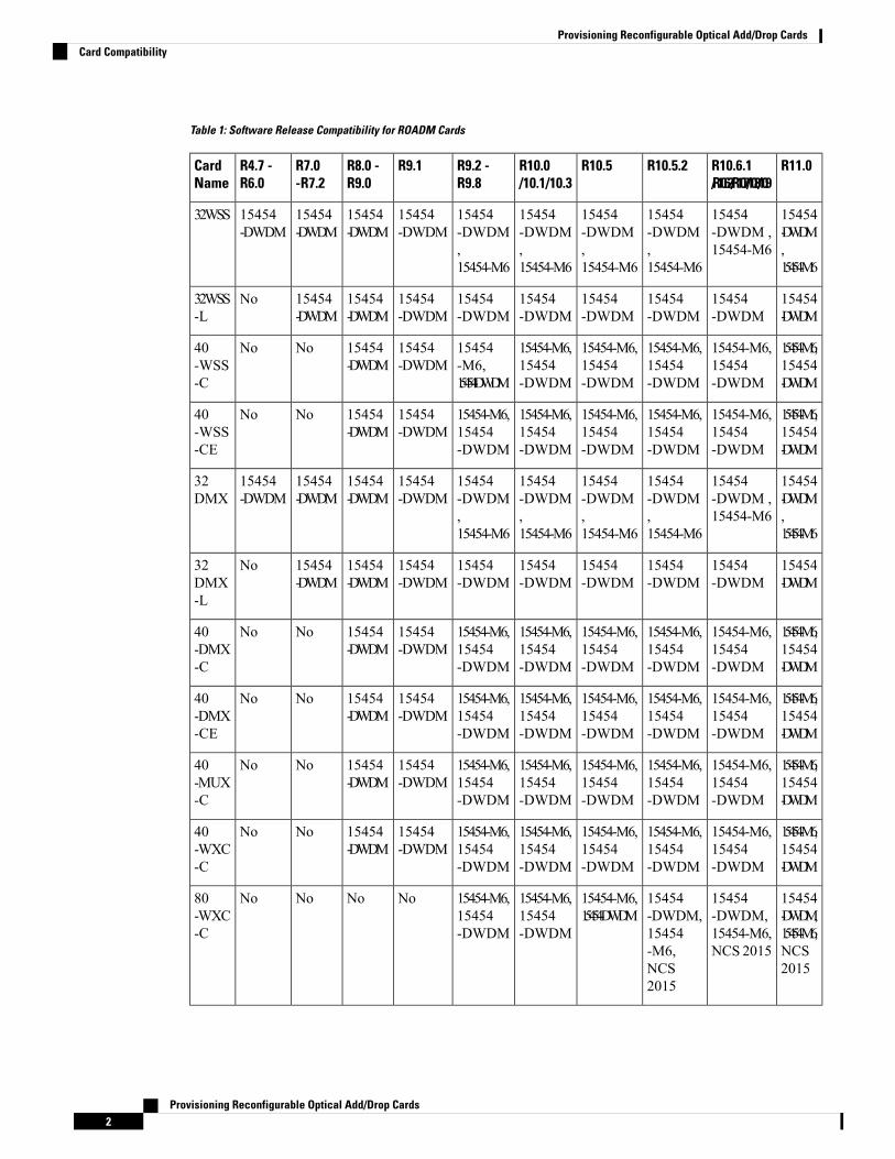
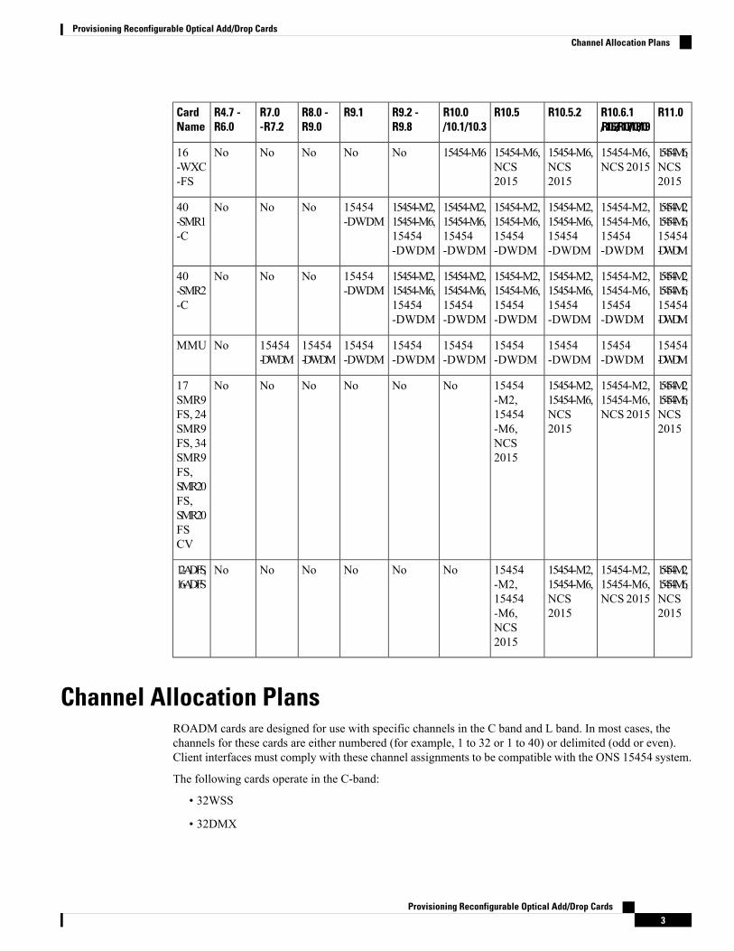
Table 1: Software Release Compatibility for ROADM Cards
R11.0R10.6.1/R10.6.2/R10.7/10.8/10.9
R10.5.2R10.5R10.0/10.1/10.3
R9.2 -R9.8
R9.1R8.0 -R9.0
R7.0-R7.2
R4.7 -R6.0
CardName
15454-DWDM,15454-M6
15454-DWDM ,15454-M6
15454-DWDM,15454-M6
15454-DWDM,15454-M6
15454-DWDM,15454-M6
15454-DWDM,15454-M6
15454-DWDM
15454-DWDM
15454-DWDM
15454-DWDM
32WSS
15454-DWDM
15454-DWDM
15454-DWDM
15454-DWDM
15454-DWDM
15454-DWDM
15454-DWDM
15454-DWDM
15454-DWDM
No32WSS-L
15454-M6,15454-DWDM
15454-M6,15454-DWDM
15454-M6,15454-DWDM
15454-M6,15454-DWDM
15454-M6,15454-DWDM
15454-M6,15454-DWDM
15454-DWDM
15454-DWDM
NoNo40-WSS-C
15454-M6,15454-DWDM
15454-M6,15454-DWDM
15454-M6,15454-DWDM
15454-M6,15454-DWDM
15454-M6,15454-DWDM
15454-M6,15454-DWDM
15454-DWDM
15454-DWDM
NoNo40-WSS-CE
15454-DWDM,15454-M6
15454-DWDM ,15454-M6
15454-DWDM,15454-M6
15454-DWDM,15454-M6
15454-DWDM,15454-M6
15454-DWDM,15454-M6
15454-DWDM
15454-DWDM
15454-DWDM
15454-DWDM
32DMX
15454-DWDM
15454-DWDM
15454-DWDM
15454-DWDM
15454-DWDM
15454-DWDM
15454-DWDM
15454-DWDM
15454-DWDM
No32DMX-L
15454-M6,15454-DWDM
15454-M6,15454-DWDM
15454-M6,15454-DWDM
15454-M6,15454-DWDM
15454-M6,15454-DWDM
15454-M6,15454-DWDM
15454-DWDM
15454-DWDM
NoNo40-DMX-C
15454-M6,15454-DWDM
15454-M6,15454-DWDM
15454-M6,15454-DWDM
15454-M6,15454-DWDM
15454-M6,15454-DWDM
15454-M6,15454-DWDM
15454-DWDM
15454-DWDM
NoNo40-DMX-CE
15454-M6,15454-DWDM
15454-M6,15454-DWDM
15454-M6,15454-DWDM
15454-M6,15454-DWDM
15454-M6,15454-DWDM
15454-M6,15454-DWDM
15454-DWDM
15454-DWDM
NoNo40-MUX-C
15454-M6,15454-DWDM
15454-M6,15454-DWDM
15454-M6,15454-DWDM
15454-M6,15454-DWDM
15454-M6,15454-DWDM
15454-M6,15454-DWDM
15454-DWDM
15454-DWDM
NoNo40-WXC-C
15454-DWDM,15454-M6,NCS2015
15454-DWDM,15454-M6,NCS 2015
15454-DWDM,15454-M6,NCS2015
15454-M6,15454-DWDM
15454-M6,15454-DWDM
15454-M6,15454-DWDM
NoNoNoNo80-WXC-C
Provisioning Reconfigurable Optical Add/Drop Cards2
Provisioning Reconfigurable Optical Add/Drop CardsCard Compatibility
R11.0R10.6.1/R10.6.2/R10.7/10.8/10.9
R10.5.2R10.5R10.0/10.1/10.3
R9.2 -R9.8
R9.1R8.0 -R9.0
R7.0-R7.2
R4.7 -R6.0
CardName
15454-M6,NCS2015
15454-M6,NCS 2015
15454-M6,NCS2015
15454-M6,NCS2015
15454-M6NoNoNoNoNo16-WXC-FS
15454-M2,15454-M6,15454-DWDM
15454-M2,15454-M6,15454-DWDM
15454-M2,15454-M6,15454-DWDM
15454-M2,15454-M6,15454-DWDM
15454-M2,15454-M6,15454-DWDM
15454-M2,15454-M6,15454-DWDM
15454-DWDM
NoNoNo40-SMR1-C
15454-M2,15454-M6,15454-DWDM
15454-M2,15454-M6,15454-DWDM
15454-M2,15454-M6,15454-DWDM
15454-M2,15454-M6,15454-DWDM
15454-M2,15454-M6,15454-DWDM
15454-M2,15454-M6,15454-DWDM
15454-DWDM
NoNoNo40-SMR2-C
15454-DWDM
15454-DWDM
15454-DWDM
15454-DWDM
15454-DWDM
15454-DWDM
15454-DWDM
15454-DWDM
15454-DWDM
NoMMU
15454-M2,15454-M6,NCS2015
15454-M2,15454-M6,NCS 2015
15454-M2,15454-M6,NCS2015
15454-M2,15454-M6,NCS2015
NoNoNoNoNoNo17SMR9FS, 24SMR9FS, 34SMR9FS,SMR20FS,SMR20FSCV
15454-M2,15454-M6,NCS2015
15454-M2,15454-M6,NCS 2015
15454-M2,15454-M6,NCS2015
15454-M2,15454-M6,NCS2015
NoNoNoNoNoNo12-AD-FS,16-AD-FS
Channel Allocation PlansROADM cards are designed for use with specific channels in the C band and L band. In most cases, thechannels for these cards are either numbered (for example, 1 to 32 or 1 to 40) or delimited (odd or even).Client interfaces must comply with these channel assignments to be compatible with the ONS 15454 system.
The following cards operate in the C-band:
• 32WSS
• 32DMX
Provisioning Reconfigurable Optical Add/Drop Cards3
Provisioning Reconfigurable Optical Add/Drop CardsChannel Allocation Plans
• 32DMX-C
• 40-MUX-C
• 40-WXC-C
• 80-WXC-C
• 40-SMR1-C
• 40-SMR2-C
• MMU
The following add drop cards utilize the L-band DWDM channels:
• 32WSS-L
• 32DMX-L
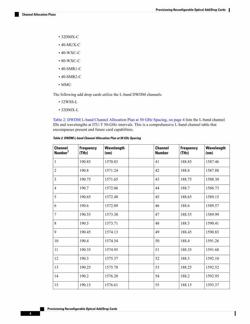
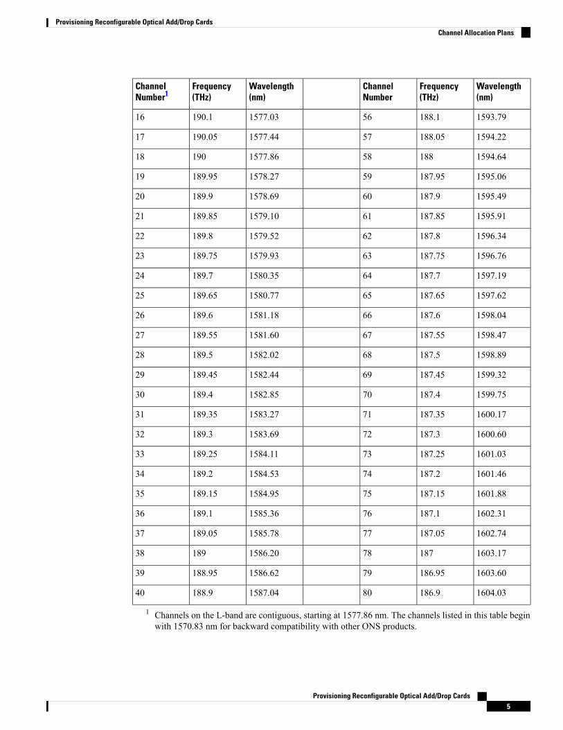
Table 2: DWDM L-band Channel Allocation Plan at 50 GHz Spacing, on page 4 lists the L-band channelIDs and wavelengths at ITU-T 50-GHz intervals. This is a comprehensive L-band channel table thatencompasses present and future card capabilities.
Table 2: DWDM L-band Channel Allocation Plan at 50 GHz Spacing
Wavelength(nm)
Frequency(THz)
ChannelNumber
Wavelength(nm)
Frequency(THz)
ChannelNumber1
1587.46188.85411570.83190.851
1587.88188.8421571.24190.82
1588.30188.75431571.65190.753
1588.73188.7441572.06190.74
1589.15188.65451572.48190.655
1589.57188.6461572.89190.66
1589.99188.55471573.30190.557
1590.41188.5481573.71190.58
1590.83188.45491574.13190.459
1591.26188.4501574.54190.410
1591.68188.35511574.95190.3511
1592.10188.3521575.37190.312
1592.52188.25531575.78190.2513
1592.95188.2541576.20190.214
1593.37188.15551576.61190.1515
Provisioning Reconfigurable Optical Add/Drop Cards4
Provisioning Reconfigurable Optical Add/Drop CardsChannel Allocation Plans
Wavelength(nm)
Frequency(THz)
ChannelNumber
Wavelength(nm)
Frequency(THz)
ChannelNumber1
1593.79188.1561577.03190.116
1594.22188.05571577.44190.0517
1594.64188581577.8619018
1595.06187.95591578.27189.9519
1595.49187.9601578.69189.920
1595.91187.85611579.10189.8521
1596.34187.8621579.52189.822
1596.76187.75631579.93189.7523
1597.19187.7641580.35189.724
1597.62187.65651580.77189.6525
1598.04187.6661581.18189.626
1598.47187.55671581.60189.5527
1598.89187.5681582.02189.528
1599.32187.45691582.44189.4529
1599.75187.4701582.85189.430
1600.17187.35711583.27189.3531
1600.60187.3721583.69189.332
1601.03187.25731584.11189.2533
1601.46187.2741584.53189.234
1601.88187.15751584.95189.1535
1602.31187.1761585.36189.136
1602.74187.05771585.78189.0537
1603.17187781586.2018938
1603.60186.95791586.62188.9539
1604.03186.9801587.04188.940
1 Channels on the L-band are contiguous, starting at 1577.86 nm. The channels listed in this table beginwith 1570.83 nm for backward compatibility with other ONS products.
Provisioning Reconfigurable Optical Add/Drop Cards5
Provisioning Reconfigurable Optical Add/Drop CardsChannel Allocation Plans

Safety LabelsFor information about safety labels, see the section, Class 1M Laser Product Cards.
32WSS and 32WSS-L Cards(Cisco ONS 15454 only)
The two-slot 32-ChannelWavelength Selective Switch (32WSS) and 32-ChannelWavelength Selective SwitchL-Band (32WSS-L) cards perform channel add/drop processing within the DWDM node. The 32WSS or32WSS-L card can be installed in the following pairs of slots:
• Slots 1 and 2
• Slots 3 and 4
• Slots 5 and 6
• Slots 12 and 13
• Slots 14 and 15
• Slots 16 and 17
The 32WSS or 32WSS-L cards has six types of ports:
• ADD RX ports (1 to 32): These ports are used for adding channels (listed in Table 4: Channel AllocationPlan, on page 8 or Table 5: Channel Allocation Plan, on page 9). Each add channel is associated withan individual switch element that selects whether that channel is added. Each add port has optical powerregulation provided by a variable optical attenuator (VOA). The 32WSS has four physical receiveconnectors that accept multifiber push-on (MPO) cables on its front panel for the client input interfaces.Each MPO cable breaks out into eight separate cables.
• EXPRX port: The EXPRX port receives an optical signal from another 32WSS card in the same networkelement (NE).
• EXP TX port: The EXP TX port sends an optical signal to the other 32WSS card within the NE.
• COM TX port: The COM TX (line input) port sends an aggregate optical signal to a booster amplifiercard (for example, OPT-BST) for transmission outside of the NE.
• COMRX port: The COMRX port receives the optical signal from a preamplifier (such as the OPT-PRE)and sends it to the optical splitter.
• DROP TX port: The DROP TX port sends the split-off optical signal containing drop channels to the32DMX card, where the channels are further processed and dropped.
Aggregate optical signals that enter the EXP RX and COM RX port are processed in two ways:
• EXP RX Port Add Channel/Pass-through Processing
The incoming optical signal is received at the EXP RX port from the other 32WSS card within the NE.The incoming aggregate optical signal is demultiplexed into 32 individual wavelengths, or channels.Each channel is then individually processed by the optical switch, which performs add/pass-through
Provisioning Reconfigurable Optical Add/Drop Cards6
Provisioning Reconfigurable Optical Add/Drop CardsSafety Labels
processing. By using software controls, the switch either selects the optical channel coming in from thedemultiplexer (that is, the pass-through channel) or it selects the external ADD channel. If the ADD portchannel is selected this channel is transmitted and the optical signal coming from the demultiplexer isblocked.
After the optical switch stage, all of the channels are multiplexed into an aggregate optical signal, whichis sent out on the COM TX port. The output is typically connected to an OPT-AMP-L or OPT-BST-Ecard (in the event a booster amplifier is needed) or to an OSC-CSM card (if no amplification is needed).
• COM RX Port Optical Splitter Processing
The COMRX port receives the incoming optical signal and directs it to the 32WSS card’s optical splitter.The splitter optically diverts channels that are designated to be dropped to the DROPTX port. The DROPTX port is typically connected to the COM RX port of the 32DMX where the drop channels are beingdropped. Channels that are not dropped pass-through the optical splitter and flow out of the 32WSS cardEXP TX port. Typically, this optical signal is connected to the other 32WSS module within the NE.
The COM TX value can be measured by either a physical or a virtual photodiode of the 32WSS card. If thevendor ID of the 32WSS card is between 1024 (0x400) and 2047 (0x800) the COM TX value is measured byphysical photodiode. If the vendor ID of the 32WSS card is greater than 2048 (0x800), the COM TX valueis measured by the virtual photodiode. For COMTX values measured by virtual photodiode, check the valuesat the RX port in the downstream of the COM TX port (COM-RX port on OPT-BST or OSC-CSM card).
For more information about the 32WSS or 32WSS-L card, seehttp://www.cisco.com/en/US/prod/collateral/optical/ps5724/ps2006/ps5320/product_data_sheet0900aecd803fc52f.html.
32WSS and 32WSS-L ROADM FunctionalityTo implement ROADM functionality, the 32WSS (or 32WSS-L) card works in combination with the 32DMX(or 32DMX-L) card. As a ROADMnode, the node can be configured to add or drop individual optical channelsusing CTC, Cisco Transport Planner, and Cisco Transport Manager (CTM). ROADM functionality using the32WSS (or 32WSS-L) card requires two 32DMX (or 32DMX-L) single-slot cards and two 32WSS (or32WSS-L) double-slot cards (totalling six slots needed in the chassis).
For other cards’ ROADM functionality, see that card’s description in this chapter. For a diagram of a typicalROADM configuration, see the section, ROADMNode in theCisco ONS 15454 DWDMNetwork OperationsGuide.
A terminal site can be configured using only a 32WSS (or 32WSS-L) card and a 32DMX (or 32DMX-L) cardplugged into the east or west side of the shelf.
Note
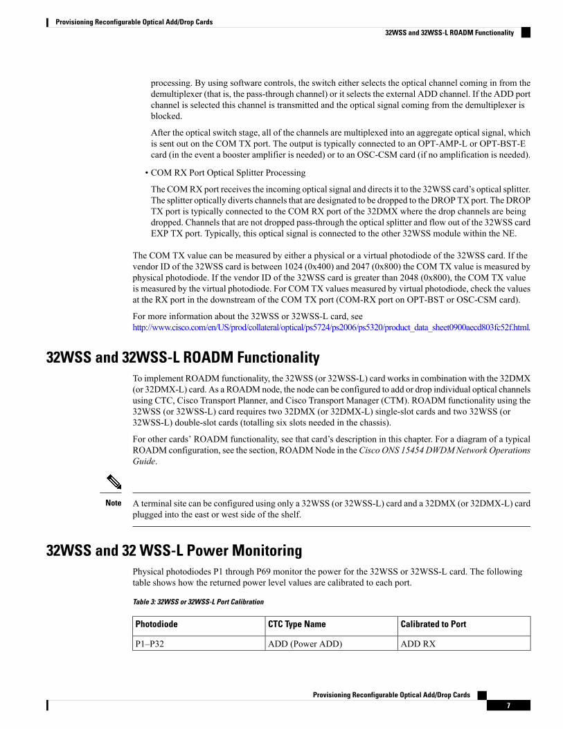
32WSS and 32 WSS-L Power MonitoringPhysical photodiodes P1 through P69 monitor the power for the 32WSS or 32WSS-L card. The followingtable shows how the returned power level values are calibrated to each port.
Table 3: 32WSS or 32WSS-L Port Calibration
Calibrated to PortCTC Type NamePhotodiode
ADD RXADD (Power ADD)P1–P32
Provisioning Reconfigurable Optical Add/Drop Cards7
Provisioning Reconfigurable Optical Add/Drop Cards32WSS and 32WSS-L ROADM Functionality
Calibrated to PortCTC Type NamePhotodiode
COM TXPASS THROUGHP33–P642
COM TXADD (Power)
EXP TXOUT EXPP65
EXP RXIN EXPP66
COM TXOUT COMP67
COM RXIN COMP68
DROP TXDROPP69
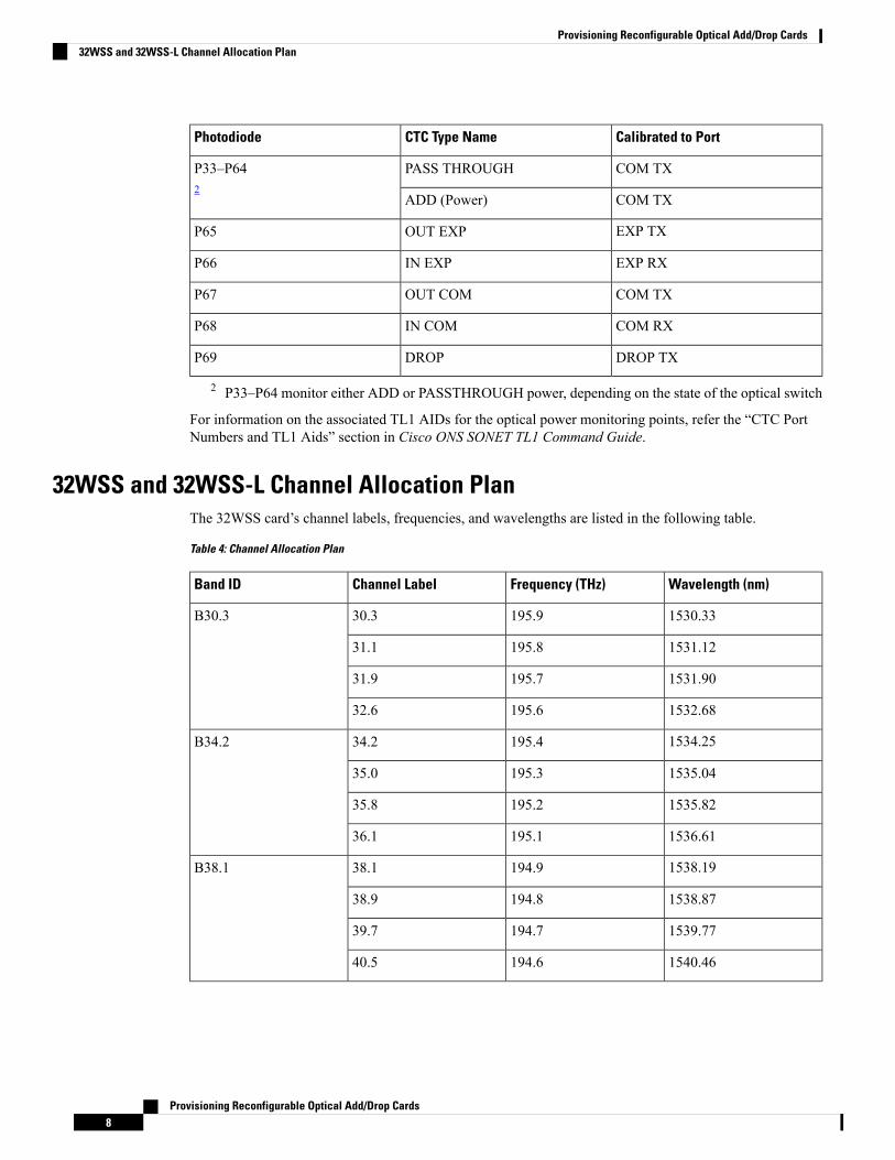
2 P33–P64 monitor either ADD or PASSTHROUGH power, depending on the state of the optical switch
For information on the associated TL1 AIDs for the optical power monitoring points, refer the “CTC PortNumbers and TL1 Aids” section in Cisco ONS SONET TL1 Command Guide.
32WSS and 32WSS-L Channel Allocation PlanThe 32WSS card’s channel labels, frequencies, and wavelengths are listed in the following table.
Table 4: Channel Allocation Plan
Wavelength (nm)Frequency (THz)Channel LabelBand ID
1530.33195.930.3B30.3
1531.12195.831.1
1531.90195.731.9
1532.68195.632.6
1534.25195.434.2B34.2
1535.04195.335.0
1535.82195.235.8
1536.61195.136.1
1538.19194.938.1B38.1
1538.87194.838.9
1539.77194.739.7
1540.46194.640.5
Provisioning Reconfigurable Optical Add/Drop Cards8
Provisioning Reconfigurable Optical Add/Drop Cards32WSS and 32WSS-L Channel Allocation Plan
Wavelength (nm)Frequency (THz)Channel LabelBand ID
1542.14194.442.1B42.1
1542.94194.342.9
1543.73194.243.7
1544.53194.144.5
1546.12193.946.1B46.1
1546.92193.846.9
1547.72193.747.7
1548.51193.648.5
1550.12193.450.1B50.1
1550.92193.350.9
1551.72193.251.7
1552.52193.152.5
1554.13192.954.1B54.1
1554.94192.854.9
1555.75192.755.7
1556.55192.656.5
1558.17192.458.1B58.1
1558.98192.358.9
1559.79192.259.7
1560.61192.160.6
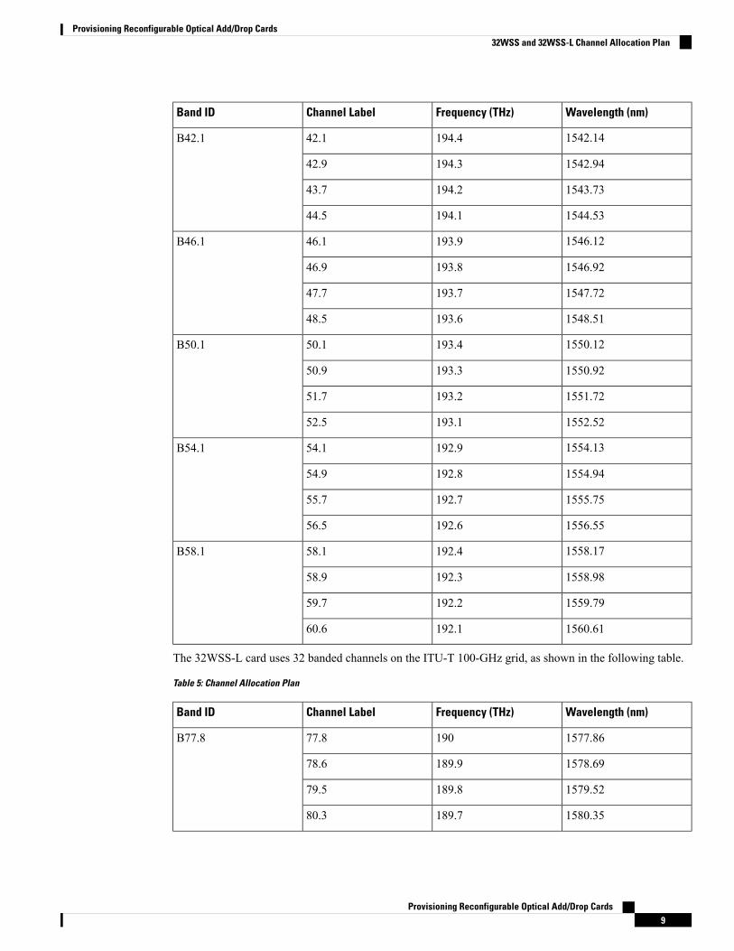
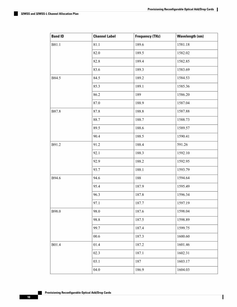
The 32WSS-L card uses 32 banded channels on the ITU-T 100-GHz grid, as shown in the following table.
Table 5: Channel Allocation Plan
Wavelength (nm)Frequency (THz)Channel LabelBand ID
1577.8619077.8B77.8
1578.69189.978.6
1579.52189.879.5
1580.35189.780.3
Provisioning Reconfigurable Optical Add/Drop Cards9
Provisioning Reconfigurable Optical Add/Drop Cards32WSS and 32WSS-L Channel Allocation Plan
Wavelength (nm)Frequency (THz)Channel LabelBand ID
1581.18189.681.1B81.1
1582.02189.582.0
1582.85189.482.8
1583.69189.383.6
1584.53189.284.5B84.5
1585.36189.185.3
1586.2018986.2
1587.04188.987.0
1587.88188.887.8B87.8
1588.73188.788.7
1589.57188.689.5
1590.41188.590.4
591.26188.491.2B91.2
1592.10188.392.1
1592.95188.292.9
1593.79188.193.7
1594.6418894.6B94.6
1595.49187.995.4
1596.34187.896.3
1597.19187.797.1
1598.04187.698.0B98.0
1598.89187.598.8
1599.75187.499.7
1600.60187.300.6
1601.46187.201.4B01.4
1602.31187.102.3
1603.1718703.1
1604.03186.904.0
Provisioning Reconfigurable Optical Add/Drop Cards10
Provisioning Reconfigurable Optical Add/Drop Cards32WSS and 32WSS-L Channel Allocation Plan
Related Procedures for 32WSS and 32WSS-L CardsThe following section lists procedures and tasks related to the configuration of the 32WSS or 32WSS-L cards:
• NTP-G140 Installing Fiber-Optic Cables Between Terminal, Hub, or ROADM Nodes
• NTP-G152 Creating and Verifying Internal Patchcords
• NTP-G37 Running Automatic Node Setup
• NTP-G59 Creating, Deleting, and Managing Optical Channel Network Connections
• NTP-G51 Verify DWDM Node Turn Up
• DLP-G141 View Optical Power Statistics for 32MUX-O, 32WSS, 32WSS-L, 32DMX-O, 32DMX,32DMX-L, 40-WSS-C, 40-WSS-CE, 40-WXC-C, 80-WXC-C, 16-WXC-FS, 40-MUX-C, 40-DMX-C,and 40-DMX-CE Cards
• NTP-G93 Modifying the WSS Card Line Settings and PM Thresholds
32DMX and 32DMX-L Cards(Cisco ONS 15454 only)
The single-slot 32-channel demultiplexer (32DMX) or the 32-channel demultiplexer L-band (32DMX-L) cardis an optical demultiplexer. The card receives an aggregate optical signal on its COMRXport and demultiplexesit into to (32) ITU-T 100-GHz-spaced channels. The 32DMX or 32DMX-L card can be installed in Slots 1to 6 and in Slots 12 to 17. The 32DMX-L card is particularly well suited for use in networks that employ DSfiber or SMF-28 single-mode fiber.
The 32DMX or 32DMX-L card has two types of ports:
• COMRX port: COMRX is the input port for the aggregate optical signal being demultiplexed. This portis supported by a VOA for optical power regulation and a photodiode for optical power monitoring.
• DROP TX ports (1 to 32): On its output, the 32DMX provides 32 drop ports that are typically used fordropping channels within the ROADM node. These ports are connected using four 8-fiber MPO ribbonconnectors. The incoming optical signal to the demultiplexer comes into the COM RX port. This inputport is connected using a single LC duplex optical connector. Each drop port has a photodiode for opticalpower monitoring. Unlike the two-slot 32DMX-O demultiplexer, the drop ports on the 32DMX do nothave a VOA per channel for optical power regulation.
For more information about the 32DMX or 32DMX-L card, seehttp://www.cisco.com/en/US/prod/collateral/optical/ps5724/ps2006/ps5320/product_data_sheet0900aecd803fc52f.html.
32DMX and 32DMX-L ROADM FunctionalityThe 32DMX (or 32DMX-L) card works in combination with the 32WSS (or 32WSS-L) card to implementROADM functionality. As a ROADM node, the node can be configured to add or drop individual opticalchannels using CTC, Cisco Transport Planner, and CTM. ROADM functionality using the 32DMX (or32DMX-L) card requires two 32DMX (or 32DMX-L) single-slot cards and two 32WSS (or 32WSS-L)double-slot cards (for six slots total in the chassis).
Provisioning Reconfigurable Optical Add/Drop Cards11
Provisioning Reconfigurable Optical Add/Drop CardsRelated Procedures for 32WSS and 32WSS-L Cards
For information about the ROADM functionality for other cards, see that card’s description in this chapter.For a diagram of a typical ROADM configuration, see the section, ROADM Node in the Cisco ONS 15454DWDM Network Operations Guide.
A terminal site can be configured using only a 32WSS (or 32WSS-L) card and a 32DMX or 32WSS-L) cardplugged into the east or west side of the shelf.
Note
32DMX and 32DMX-L Power MonitoringPhysical photodiodes P1 through P33 monitor the power for the 32DMX or 32DMX-L card. The returnedpower level values are calibrated to the ports as shown in following table.
Table 6: 32DMX or 32DMX-L Port Calibration
Calibrated to PortCTC Type NamePhotodiode
DROP TXDROPP1–P32
COM RXINPUT COMP33
For information on the associated TL1 AIDs for the optical power monitoring points, refer the “CTC PortNumbers and TL1 Aids” section in Cisco ONS SONET TL1 Command Guide.
32DMX and 32DMX-L Channel Allocation PlanThe 32DMX card’s channel labels, frequencies, and wavelengths are listed in Table 4: Channel AllocationPlan, on page 8.
The 32DMX-L card uses 32 banded channels on the ITU-T 100-GHz grid, as shown in Table 5: ChannelAllocation Plan, on page 9.
Related Procedures for 32DMX and 32DMX-L CardsThe following section lists procedures and tasks related to the configuration of the 32DMX or 32DMX-Lcards:
• NTP-G140 Installing Fiber-Optic Cables Between Terminal, Hub, or ROADM Nodes
• NTP-G152 Creating and Verifying Internal Patchcords
• NTP-G37 Running Automatic Node Setup
• NTP-G59 Creating, Deleting, and Managing Optical Channel Network Connections
• NTP-G51 Verify DWDM Node Turn Up
• DLP-G141 View Optical Power Statistics for 32MUX-O, 32WSS, 32WSS-L, 32DMX-O, 32DMX,32DMX-L, 40-WSS-C, 40-WSS-CE, 40-WXC-C, 80-WXC-C, 16-WXC-FS, 40-MUX-C, 40-DMX-C,and 40-DMX-CE Cards
• NTP-G93 Modifying the WSS Card Line Settings and PM Thresholds
Provisioning Reconfigurable Optical Add/Drop Cards12
Provisioning Reconfigurable Optical Add/Drop Cards32DMX and 32DMX-L Power Monitoring
40-DMX-C and 40-DMX-CE Card(Cisco ONS 15454 and ONS 15454 M6 only)
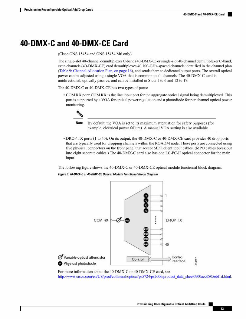
The single-slot 40-channel demultiplexer C-band (40-DMX-C) or single-slot 40-channel demultiplexer C-band,even channels (40-DMX-CE) card demultiplexes 40 100-GHz-spaced channels identified in the channel plan(Table 9: Channel Allocation Plan, on page 16), and sends them to dedicated output ports. The overall opticalpower can be adjusted using a single VOA that is common to all channels. The 40-DMX-C card isunidirectional, optically passive, and can be installed in Slots 1 to 6 and 12 to 17.
The 40-DMX-C or 40-DMX-CE has two types of ports:
• COMRX port: COMRX is the line input port for the aggregate optical signal being demultiplexed. Thisport is supported by a VOA for optical power regulation and a photodiode for per channel optical powermonitoring.
By default, the VOA is set to its maximum attenuation for safety purposes (forexample, electrical power failure). A manual VOA setting is also available.
Note
• DROP TX ports (1 to 40): On its output, the 40-DMX-C or 40-DMX-CE card provides 40 drop portsthat are typically used for dropping channels within the ROADM node. These ports are connected usingfive physical connectors on the front panel that accept MPO client input cables. (MPO cables break outinto eight separate cables.) The 40-DMX-C card also has one LC-PC-II optical connector for the maininput.
The following figure shows the 40-DMX-C or 40-DMX-CE optical module functional block diagram.Figure 1: 40-DMX-C or 40-DMX-CE Optical Module Functional Block Diagram
For more information about the 40-DMX-C or 40-DMX-CE card, seehttp://www.cisco.com/en/US/prod/collateral/optical/ps5724/ps2006/product_data_sheet0900aecd805ebf1d.html.
Provisioning Reconfigurable Optical Add/Drop Cards13
Provisioning Reconfigurable Optical Add/Drop Cards40-DMX-C and 40-DMX-CE Card
40-DMX-C and 40-DMX-CE ROADM FunctionalityThe 40-DMX-C (or 40-DMX-CE) card works in combination with the 40-WSS-C (or 40-WSS-CE) card toimplement ROADM functionality. As a ROADM node, the node can be configured at the optical channellevel using CTC, Cisco Transport Planner, and CTM. ROADM functionality using the 40-DMX-C (or40-DMX-CE) card requires two single-slot 40-DMX-C (or 40-DMX-CE) cards and two 40-WSS-C (or40-WSS-CE) double-slot cards (for a total of six slots in the chassis).
For other cards’ ROADM functionality, see that card’s description in this chapter. For a diagram of a typicalROADMconfiguration, see the section, ROADMNode in theCiscoONS 15454DWDMNetworkConfigurationGuide.
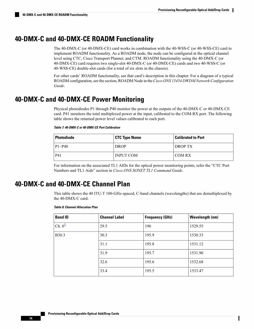
40-DMX-C and 40-DMX-CE Power MonitoringPhysical photodiodes P1 through P40 monitor the power at the outputs of the 40-DMX-C or 40-DMX-CEcard. P41 monitors the total multiplexed power at the input, calibrated to the COM-RX port. The followingtable shows the returned power level values calibrated to each port.
Table 7: 40-DMX-C or 40-DMX-CE Port Calibration
Calibrated to PortCTC Type NamePhotodiode
DROP TXDROPP1–P40
COM RXINPUT COMP41
For information on the associated TL1 AIDs for the optical power monitoring points, refer the “CTC PortNumbers and TL1 Aids” section in Cisco ONS SONET TL1 Command Guide.
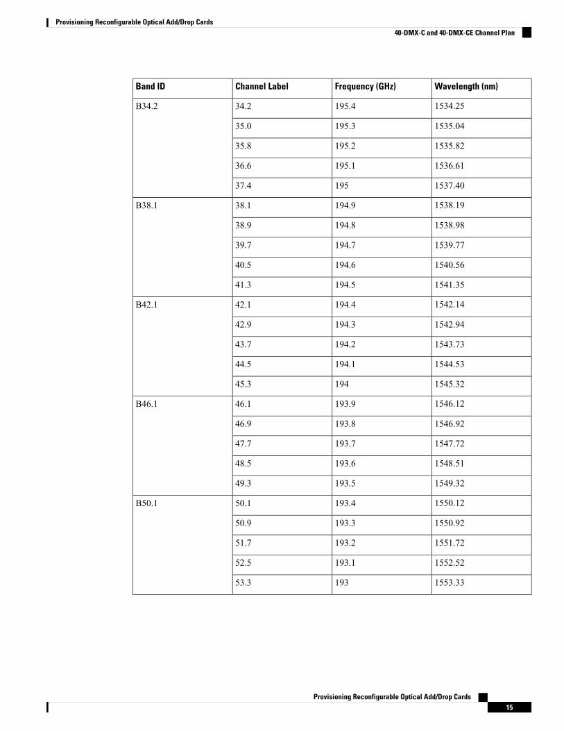
40-DMX-C and 40-DMX-CE Channel PlanThis table shows the 40 ITU-T 100-GHz-spaced, C-band channels (wavelengths) that are demultiplexed bythe 40-DMX-C card.
Table 8: Channel Allocation Plan
Wavelength (nm)Frequency (GHz)Channel LabelBand ID
1529.5519629.5Ch. 03
1530.33195.930.3B30.3
1531.12195.831.1
1531.90195.731.9
1532.68195.632.6
1533.47195.533.4
Provisioning Reconfigurable Optical Add/Drop Cards14
Provisioning Reconfigurable Optical Add/Drop Cards40-DMX-C and 40-DMX-CE ROADM Functionality
Wavelength (nm)Frequency (GHz)Channel LabelBand ID
1534.25195.434.2B34.2
1535.04195.335.0
1535.82195.235.8
1536.61195.136.6
1537.4019537.4
1538.19194.938.1B38.1
1538.98194.838.9
1539.77194.739.7
1540.56194.640.5
1541.35194.541.3
1542.14194.442.1B42.1
1542.94194.342.9
1543.73194.243.7
1544.53194.144.5
1545.3219445.3
1546.12193.946.1B46.1
1546.92193.846.9
1547.72193.747.7
1548.51193.648.5
1549.32193.549.3
1550.12193.450.1B50.1
1550.92193.350.9
1551.72193.251.7
1552.52193.152.5
1553.3319353.3
Provisioning Reconfigurable Optical Add/Drop Cards15
Provisioning Reconfigurable Optical Add/Drop Cards40-DMX-C and 40-DMX-CE Channel Plan
Wavelength (nm)Frequency (GHz)Channel LabelBand ID
1554.13192.954.1B54.1
1554.94192.854.9
1555.75192.755.7
1556.55192.656.5
1557.36192.557.3
1558.17192.458.1B58.1
1558.98192.358.9
1559.79192.259.7
1560.61192.160.6
1561.4219261.4
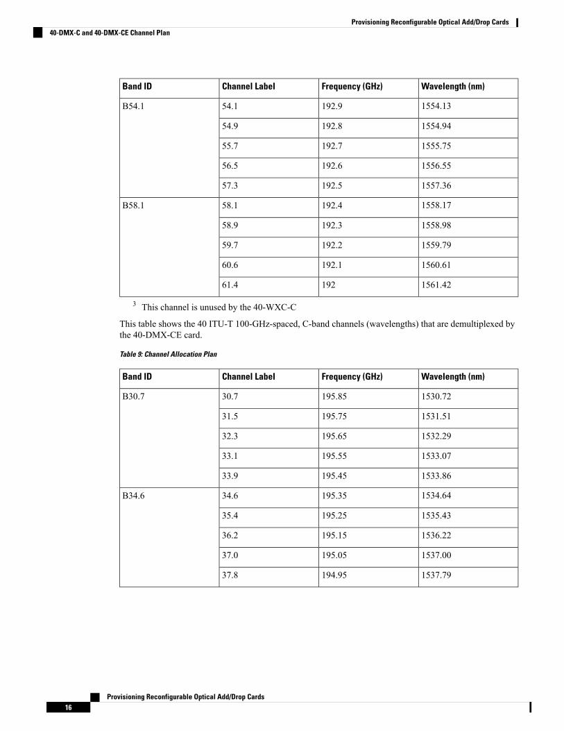
3 This channel is unused by the 40-WXC-C
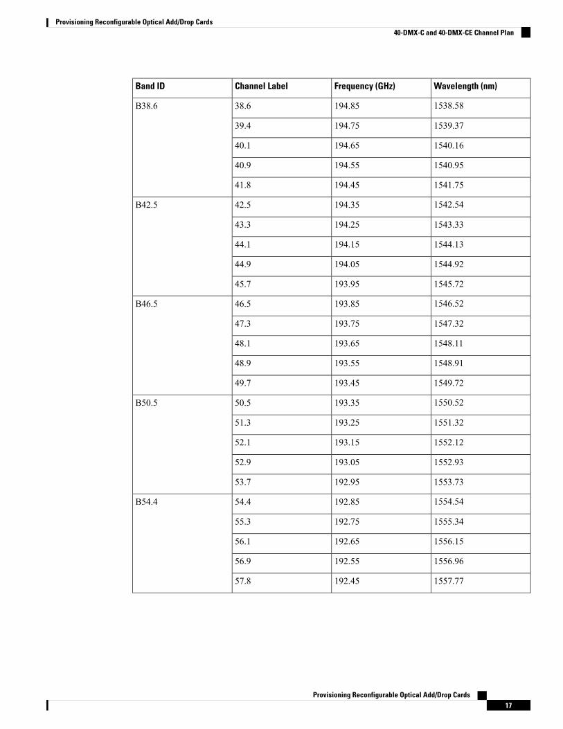
This table shows the 40 ITU-T 100-GHz-spaced, C-band channels (wavelengths) that are demultiplexed bythe 40-DMX-CE card.
Table 9: Channel Allocation Plan
Wavelength (nm)Frequency (GHz)Channel LabelBand ID
1530.72195.8530.7B30.7
1531.51195.7531.5
1532.29195.6532.3
1533.07195.5533.1
1533.86195.4533.9
1534.64195.3534.6B34.6
1535.43195.2535.4
1536.22195.1536.2
1537.00195.0537.0
1537.79194.9537.8
Provisioning Reconfigurable Optical Add/Drop Cards16
Provisioning Reconfigurable Optical Add/Drop Cards40-DMX-C and 40-DMX-CE Channel Plan
Wavelength (nm)Frequency (GHz)Channel LabelBand ID
1538.58194.8538.6B38.6
1539.37194.7539.4
1540.16194.6540.1
1540.95194.5540.9
1541.75194.4541.8
1542.54194.3542.5B42.5
1543.33194.2543.3
1544.13194.1544.1
1544.92194.0544.9
1545.72193.9545.7
1546.52193.8546.5B46.5
1547.32193.7547.3
1548.11193.6548.1
1548.91193.5548.9
1549.72193.4549.7
1550.52193.3550.5B50.5
1551.32193.2551.3
1552.12193.1552.1
1552.93193.0552.9
1553.73192.9553.7
1554.54192.8554.4B54.4
1555.34192.7555.3
1556.15192.6556.1
1556.96192.5556.9
1557.77192.4557.8
Provisioning Reconfigurable Optical Add/Drop Cards17
Provisioning Reconfigurable Optical Add/Drop Cards40-DMX-C and 40-DMX-CE Channel Plan
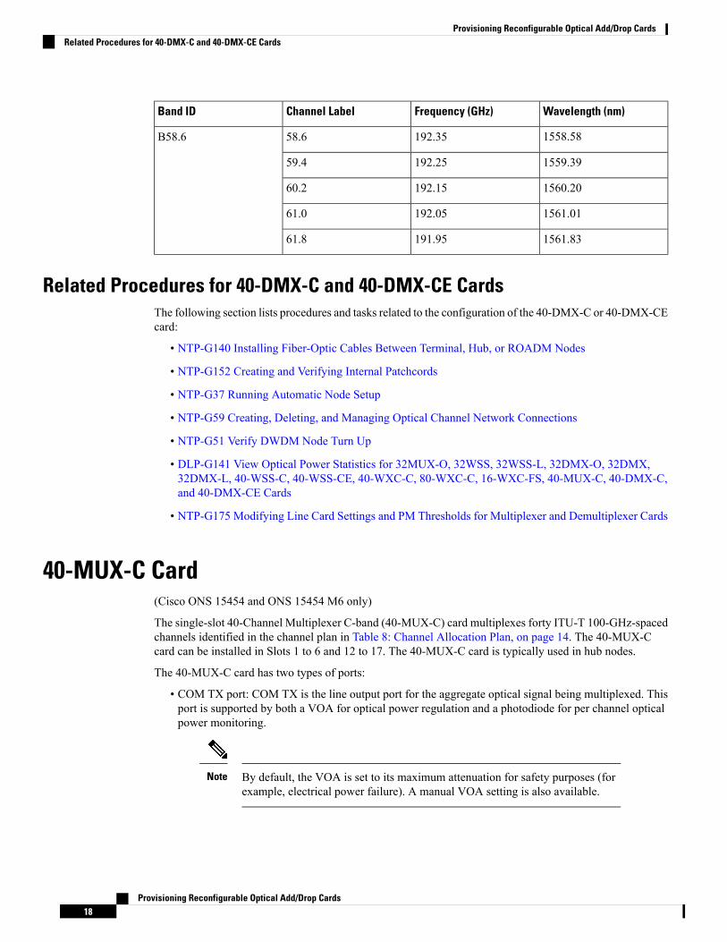
Wavelength (nm)Frequency (GHz)Channel LabelBand ID
1558.58192.3558.6B58.6
1559.39192.2559.4
1560.20192.1560.2
1561.01192.0561.0
1561.83191.9561.8
Related Procedures for 40-DMX-C and 40-DMX-CE CardsThe following section lists procedures and tasks related to the configuration of the 40-DMX-C or 40-DMX-CEcard:
• NTP-G140 Installing Fiber-Optic Cables Between Terminal, Hub, or ROADM Nodes
• NTP-G152 Creating and Verifying Internal Patchcords
• NTP-G37 Running Automatic Node Setup
• NTP-G59 Creating, Deleting, and Managing Optical Channel Network Connections
• NTP-G51 Verify DWDM Node Turn Up
• DLP-G141 View Optical Power Statistics for 32MUX-O, 32WSS, 32WSS-L, 32DMX-O, 32DMX,32DMX-L, 40-WSS-C, 40-WSS-CE, 40-WXC-C, 80-WXC-C, 16-WXC-FS, 40-MUX-C, 40-DMX-C,and 40-DMX-CE Cards
• NTP-G175 Modifying Line Card Settings and PM Thresholds for Multiplexer and Demultiplexer Cards
40-MUX-C Card(Cisco ONS 15454 and ONS 15454 M6 only)
The single-slot 40-Channel Multiplexer C-band (40-MUX-C) card multiplexes forty ITU-T 100-GHz-spacedchannels identified in the channel plan in Table 8: Channel Allocation Plan, on page 14. The 40-MUX-Ccard can be installed in Slots 1 to 6 and 12 to 17. The 40-MUX-C card is typically used in hub nodes.
The 40-MUX-C card has two types of ports:
• COM TX port: COM TX is the line output port for the aggregate optical signal being multiplexed. Thisport is supported by both a VOA for optical power regulation and a photodiode for per channel opticalpower monitoring.
By default, the VOA is set to its maximum attenuation for safety purposes (forexample, electrical power failure). A manual VOA setting is also available.
Note
Provisioning Reconfigurable Optical Add/Drop Cards18
Provisioning Reconfigurable Optical Add/Drop CardsRelated Procedures for 40-DMX-C and 40-DMX-CE Cards
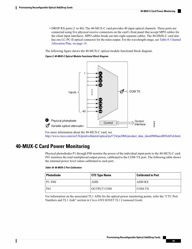
• DROP RX ports (1 to 40): The 40-MUX-C card provides 40 input optical channels. These ports areconnected using five physical receive connectors on the card’s front panel that accept MPO cables forthe client input interfaces. MPO cables break out into eight separate cables. The 40-DMX-C card alsohas one LC-PC-II optical connector for the main output. For the wavelength range, see Table 8: ChannelAllocation Plan, on page 14.
The following figure shows the 40-MUX-C optical module functional block diagram.Figure 2: 40-MUX-C Optical Module Functional Block Diagram
For more information about the 40-MUX-C card, seehttp://www.cisco.com/en/US/prod/collateral/optical/ps5724/ps2006/product_data_sheet0900aecd805ebf1d.html.
40-MUX-C Card Power MonitoringPhysical photodiodes P1 through P40 monitor the power of the individual input ports to the 40-MUX-C card.P41 monitors the total multiplexed output power, calibrated to the COM-TX port. The following table showsthe returned power level values calibrated to each port.
Table 10: 40-MUX-C Port Calibration
Calibrated to PortCTC Type NamePhotodiode
ADD RXADDP1–P40
COM-TXOUTPUT COMP41
For information on the associated TL1 AIDs for the optical power monitoring points, refer the “CTC PortNumbers and TL1 Aids” section in Cisco ONS SONET TL1 Command Guide.
Provisioning Reconfigurable Optical Add/Drop Cards19
Provisioning Reconfigurable Optical Add/Drop Cards40-MUX-C Card Power Monitoring
40-MUX-C Card Channel PlanTable 8: Channel Allocation Plan, on page 14 shows the 40 ITU-T 100-GHz-spaced, C-band channels(wavelengths) that are multiplexed by the 40-MUX-C card.
Related Procedures for 40-MUX-C CardThe following section lists procedures and tasks related to the configuration of the 40-MUX-C card:
• NTP-G140 Installing Fiber-Optic Cables Between Terminal, Hub, or ROADM Nodes
• NTP-G152 Creating and Verifying Internal Patchcords
• NTP-G37 Running Automatic Node Setup
• NTP-G59 Creating, Deleting, and Managing Optical Channel Network Connections
• NTP-G51 Verify DWDM Node Turn Up
• DLP-G141 View Optical Power Statistics for 32MUX-O, 32WSS, 32WSS-L, 32DMX-O, 32DMX,32DMX-L, 40-WSS-C, 40-WSS-CE, 40-WXC-C, 80-WXC-C, 16-WXC-FS, 40-MUX-C, 40-DMX-C,and 40-DMX-CE Cards
• NTP-G175 Modifying Line Card Settings and PM Thresholds for Multiplexer and Demultiplexer Cards
40-WSS-C and 40-WSS-CE Card(Cisco ONS 15454 and ONS 15454 M6 only)
The double-slot 40-channel wavelength selective switch C-band (40-WSS-C) or the double-slot 40-channelwavelength selective switch even-channel C-band (40-WSS-CE) card switches 40 ITU-T 100-GHz-spacedchannels identified in the channel plan (Table 8: Channel Allocation Plan, on page 14 or Table 9: ChannelAllocation Plan, on page 16) and sends them to dedicated output ports. The 40-WSS-C or 40-WSS-CE cardis bidirectional and optically passive. The card can be installed in Slots 1 to 6 and 12 to 17
The 40-WSS-C or 40-WSS-CE features include:
• Receipt of an aggregate DWDM signal into 40 output optical channels from the Line receive port (EXPRX) in one direction and from the COM-RX port in the other direction.
• Per-channel optical power monitoring using photodiodes.
• Signal splitting in a 70%-to-30% ratio, sent to the 40-DMX-C (or 40-DMX-CE) for dropping signals,then to the other 40-WSS-C (or 40-WSS-CE) card.
• Aggregate DWDM signal monitoring and control through a variable optical attenuator (VOA). In thecase of electrical power failure, the VOA is set to its maximum attenuation for safety purposes. AmanualVOA setting is also available.
Within the 40-WSS-C or 40-WSS-CE card, the first AWGopens the spectrum and each wavelength is directedto one of the ports of a 1x2 optical switch. The same wavelength can be passed through or stopped. If thepass-through wavelength is stopped, a new channel can be added at the ADD port. The card’s second AWGmultiplexes all of the wavelengths, and the aggregate signal is output through the COM-TX port.
Provisioning Reconfigurable Optical Add/Drop Cards20
Provisioning Reconfigurable Optical Add/Drop Cards40-MUX-C Card Channel Plan
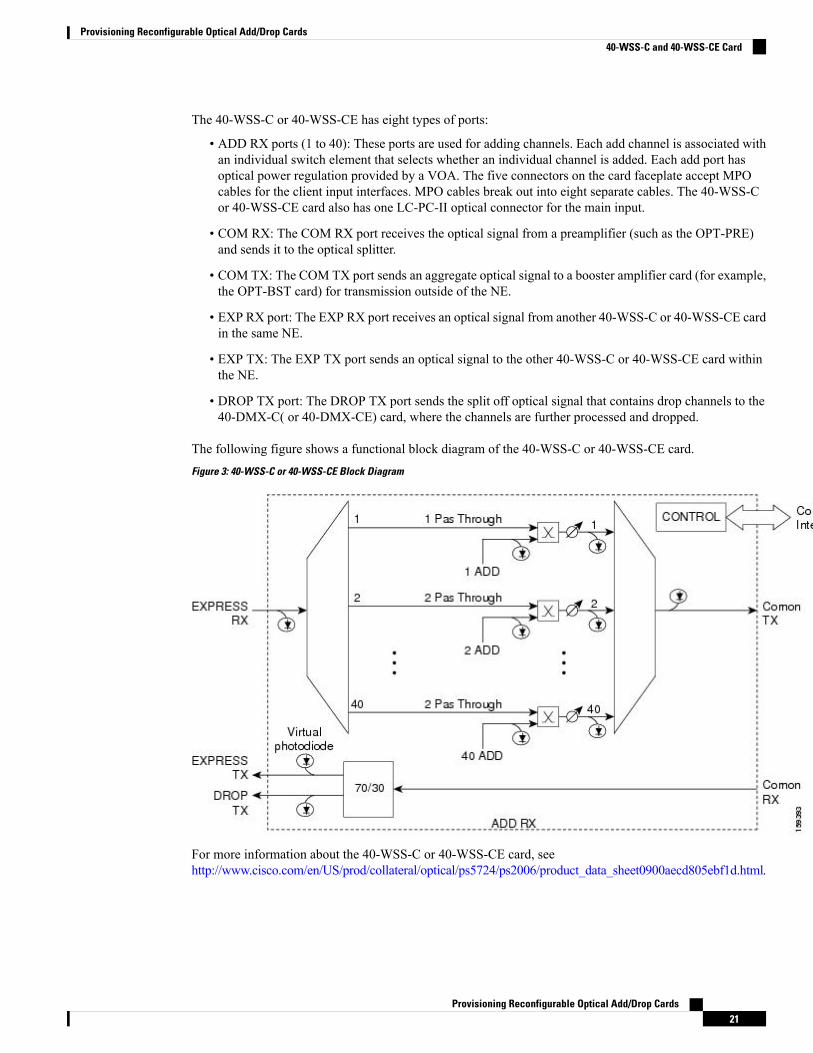
The 40-WSS-C or 40-WSS-CE has eight types of ports:
• ADD RX ports (1 to 40): These ports are used for adding channels. Each add channel is associated withan individual switch element that selects whether an individual channel is added. Each add port hasoptical power regulation provided by a VOA. The five connectors on the card faceplate accept MPOcables for the client input interfaces. MPO cables break out into eight separate cables. The 40-WSS-Cor 40-WSS-CE card also has one LC-PC-II optical connector for the main input.
• COM RX: The COM RX port receives the optical signal from a preamplifier (such as the OPT-PRE)and sends it to the optical splitter.
• COM TX: The COM TX port sends an aggregate optical signal to a booster amplifier card (for example,the OPT-BST card) for transmission outside of the NE.
• EXP RX port: The EXP RX port receives an optical signal from another 40-WSS-C or 40-WSS-CE cardin the same NE.
• EXP TX: The EXP TX port sends an optical signal to the other 40-WSS-C or 40-WSS-CE card withinthe NE.
• DROP TX port: The DROP TX port sends the split off optical signal that contains drop channels to the40-DMX-C( or 40-DMX-CE) card, where the channels are further processed and dropped.
The following figure shows a functional block diagram of the 40-WSS-C or 40-WSS-CE card.Figure 3: 40-WSS-C or 40-WSS-CE Block Diagram
For more information about the 40-WSS-C or 40-WSS-CE card, seehttp://www.cisco.com/en/US/prod/collateral/optical/ps5724/ps2006/product_data_sheet0900aecd805ebf1d.html.
Provisioning Reconfigurable Optical Add/Drop Cards21
Provisioning Reconfigurable Optical Add/Drop Cards40-WSS-C and 40-WSS-CE Card

40-WSS-C and 40-WSS-CE ROADM FunctionalityThe 40-WSS-C (or 40-WSS-CE) card works in combination with the 40-DMX-C (or 40-DMX-CE) card toimplement ROADM functionality. As a ROADM node, the node can be configured at the optical channellevel using CTC, Cisco Transport Planner, and CTM. ROADM functionality using the 40-WSS-C (or40-WSS-CE) card requires two 40-WSS-C (or 40-WSS-CE) double-slot cards and two 40-DMX-C (or40-DMX-CE) single-slot cards (for a total of six slots in the chassis).
For information about ROADM functionality for other cards, see that card’s description in this chapter. Fora diagram of a typical ROADM configuration, see the section, ROADMNode in theCisco ONS 15454 DWDMNetwork Operations Guide.
40-WSS-C and 40-WSS-CE Power MonitoringThe 40-WSS-C (or 40-WSS-CE) has physical diodes that monitor power at various locations on the card. Thefollowing table lists the physical diode descriptions.
Table 11: 40-WSS-C or 40-WSS-CE Physical Photodiode Port Calibration
Calibrated to Port(s)CTC Type NamePhysical Photodiode
DROP TXDROPP1
EXP RXEXPP2
Add i RX ports (that is, channelinput Add i RX power), up to 40ports and therefore 40 PDs
RXPDi34
COM TX port (that is, per channeloutput COM TX power) up to 40channels and therefore 40 PDs
TXPDi41
COM TX port (that is, total outputCOM TX power)
COMPD5
4 i indicates any channel from 01 through 40.
For information on the associated TL1 AIDs for the optical power monitoring points, refer the “CTC PortNumbers and TL1 Aids” section in Cisco ONS SONET TL1 Command Guide .
Additionally, the 40-WSS-C (or 40-WSS-CE) has two virtual diodes. Virtual diodes are monitor points foreach physical photodiode; they are identified with a physical diode relative to the way that the physical diodeis identified with one of the two interlink (ILK) ports. The following table lists the virtual diodes.
Table 12: 40-WSS-C or 40-WSS-CE Virtual Photodiode Port Calibration
Calibrated to Port(s)CTC Type NameVirtual Photodiode
COM RX port (total input COMRX power)
COMVPD1
EXPTX port (total output EXP TXpower)
EXPVPD2
Provisioning Reconfigurable Optical Add/Drop Cards22
Provisioning Reconfigurable Optical Add/Drop Cards40-WSS-C and 40-WSS-CE ROADM Functionality
40-WSS-C and 40-WSS-CE Channel PlanTable 8: Channel Allocation Plan, on page 14 shows the 40 ITU-T 100-GHz-spaced, C-band channels(wavelengths) that are switched by the 40-WSS-C card.
Table 9: Channel Allocation Plan, on page 16 shows the 40 ITU-T 100-GHz-spaced, C-band channels(wavelengths) that are switched by the 40-WSS-CE card.
Related Procedures for 40-WSS-C and 40-WSS-CECardsThe following section lists procedures and tasks related to the configuration of the 40-WSS-C or 40-WSS-CEcard:
• NTP-G140 Installing Fiber-Optic Cables Between Terminal, Hub, or ROADM Nodes
• NTP-G152 Creating and Verifying Internal Patchcords
• NTP-G37 Running Automatic Node Setup
• NTP-G59 Creating, Deleting, and Managing Optical Channel Network Connections
• NTP-G51 Verify DWDM Node Turn Up
• DLP-G141 View Optical Power Statistics for 32MUX-O, 32WSS, 32WSS-L, 32DMX-O, 32DMX,32DMX-L, 40-WSS-C, 40-WSS-CE, 40-WXC-C, 80-WXC-C, 16-WXC-FS, 40-MUX-C, 40-DMX-C,and 40-DMX-CE Cards
• NTP-G93 Modifying the WSS Card Line Settings and PM Thresholds
40-WXC-C Card(Cisco ONS 15454 and ONS 15454 M6 only)
The double-slot 40-channel wavelength cross-connect C-band (40-WXC-C) card selectively sends anywavelength combination coming from nine input ports to a common output port. The device can manage upto 41 channels spaced at 100GHz on each port according to the channel grid in Table 8: Channel AllocationPlan, on page 14. Each channel can be selected from any input. The card is optically passive and providesbidirectional capability. It can be installed in Slots 1 to 6 and 12 to 17.
.The 40-WXC-C card provides the following features:
• Demultiplexing, selection, and multiplexing of DWDM aggregate signal from input ports to commonoutput port.
• Aggregate DWDM signal monitoring and control through a VOA.
• VOAs are deployed in every channel path in order to regulate the channel’s optical power. In the caseof an electrical power failure, VOAs are set to their maximum attenuation value, or to a fixed andconfigurable one. The VOA can also be set manually.
• Per-channel optical power monitoring using photodiodes.
The 40-WXC-C card acts as a selector element with the following characteristics:
Provisioning Reconfigurable Optical Add/Drop Cards23
Provisioning Reconfigurable Optical Add/Drop Cards40-WSS-C and 40-WSS-CE Channel Plan
• It is able to select a wavelength from one input port and pass the wavelength through to the common outport. Simultaneously, the card can block the same wavelength coming from the other eight input ports.
• It is able to stop wavelengths from all nine inputs.
• It is able to monitor optical power and control path attenuation using per channel VOA independentlyof the wavelength input-to-out port connection.
The 40-WXC-C card has six types of ports:
• COM RX: The COM RX port receives the optical signal from a preamplifier (such as the OPT-PRE)and sends it to the optical splitter.
• COM TX: The COM TX port sends an aggregate optical signal to a booster amplifier card (for example,the OPT-BST card) for transmission outside of the NE.
• EXP TX: The EXP TX port sends an optical signal to the other 40-WXC-C card within the NE.
• MON TX: The optical service channel (OSC) monitor.
• ADD/DROP RX: The 40-WXC-C card provides 40 input optical channels. For the wavelength range,see Table 8: Channel Allocation Plan, on page 14.
• ADD/DROP TX: The DROP TX port sends the split off optical signal that contains drop channels to the40-WXC-C card, where the channels are further processed and dropped.
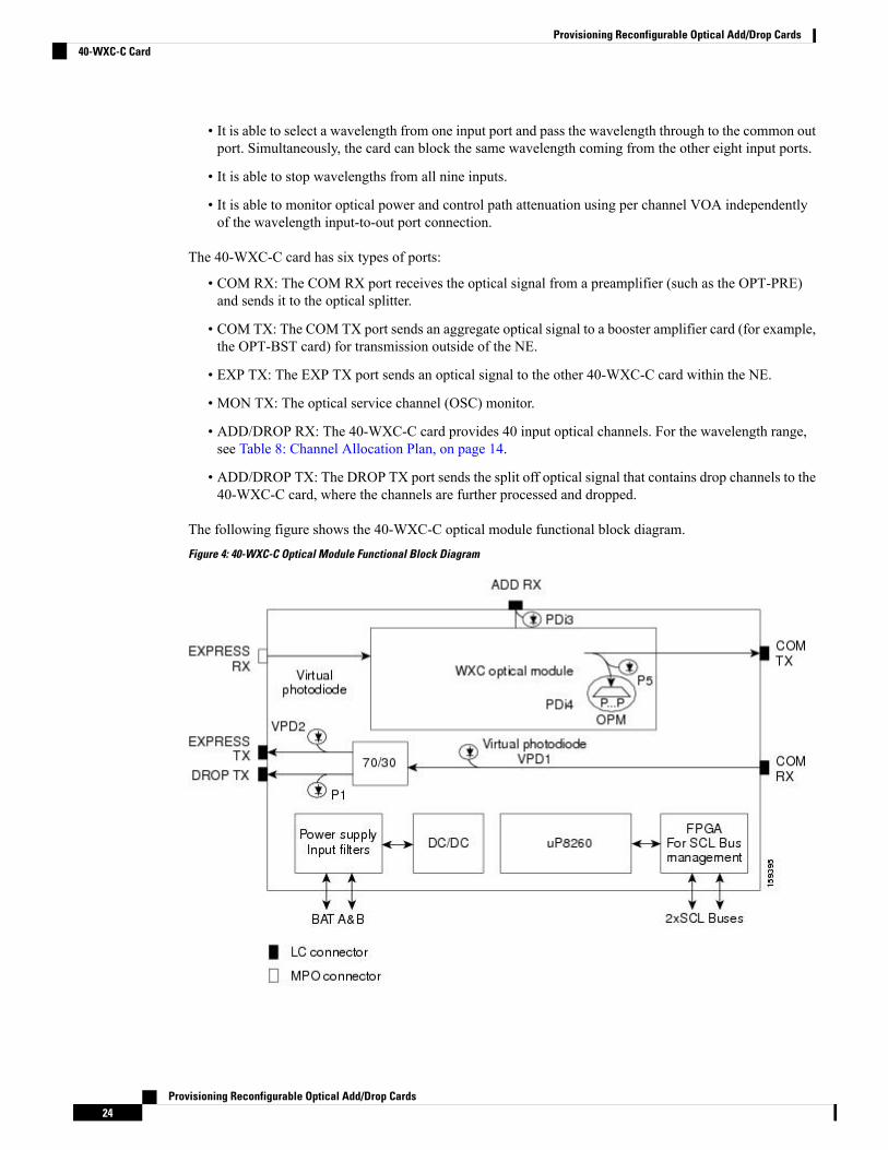
The following figure shows the 40-WXC-C optical module functional block diagram.Figure 4: 40-WXC-C Optical Module Functional Block Diagram
Provisioning Reconfigurable Optical Add/Drop Cards24
Provisioning Reconfigurable Optical Add/Drop Cards40-WXC-C Card
For more information about the 40-WXC-C card, seehttp://www.cisco.com/en/US/prod/collateral/optical/ps5724/ps2006/product_data_sheet0900aecd805ebf1d.html.
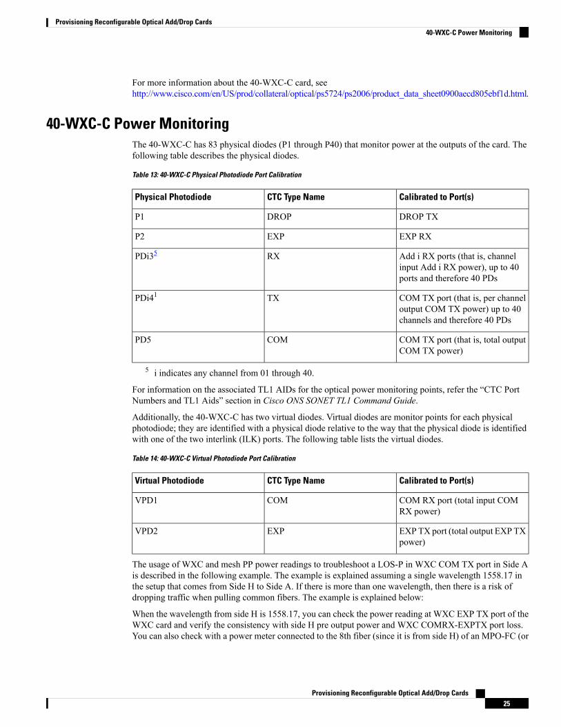
40-WXC-C Power MonitoringThe 40-WXC-C has 83 physical diodes (P1 through P40) that monitor power at the outputs of the card. Thefollowing table describes the physical diodes.
Table 13: 40-WXC-C Physical Photodiode Port Calibration
Calibrated to Port(s)CTC Type NamePhysical Photodiode
DROP TXDROPP1
EXP RXEXPP2
Add i RX ports (that is, channelinput Add i RX power), up to 40ports and therefore 40 PDs
RXPDi35
COM TX port (that is, per channeloutput COM TX power) up to 40channels and therefore 40 PDs
TXPDi41
COM TX port (that is, total outputCOM TX power)
COMPD5
5 i indicates any channel from 01 through 40.
For information on the associated TL1 AIDs for the optical power monitoring points, refer the “CTC PortNumbers and TL1 Aids” section in Cisco ONS SONET TL1 Command Guide.
Additionally, the 40-WXC-C has two virtual diodes. Virtual diodes are monitor points for each physicalphotodiode; they are identified with a physical diode relative to the way that the physical diode is identifiedwith one of the two interlink (ILK) ports. The following table lists the virtual diodes.
Table 14: 40-WXC-C Virtual Photodiode Port Calibration
Calibrated to Port(s)CTC Type NameVirtual Photodiode
COM RX port (total input COMRX power)
COMVPD1
EXPTX port (total output EXP TXpower)
EXPVPD2
The usage of WXC and mesh PP power readings to troubleshoot a LOS-P in WXC COM TX port in Side Ais described in the following example. The example is explained assuming a single wavelength 1558.17 inthe setup that comes from Side H to Side A. If there is more than one wavelength, then there is a risk ofdropping traffic when pulling common fibers. The example is explained below:
When the wavelength from side H is 1558.17, you can check the power reading at WXC EXP TX port of theWXC card and verify the consistency with side H pre output power and WXC COMRX-EXPTX port loss.You can also check with a power meter connected to the 8th fiber (since it is from side H) of an MPO-FC (or
Provisioning Reconfigurable Optical Add/Drop Cards25
Provisioning Reconfigurable Optical Add/Drop Cards40-WXC-C Power Monitoring
LC) cable connected to the TAP-TX port of the MESH-PP. This value should be consistent with the previousreading, less than the insertion loss of the installed PP-MESH. If it is consistent, the issue is with the MPObetween side A WXC and PP-MESH. If it is not consistent, the issue is with the PP-MESH or the LC-LCfrom side H. With only the PP-MESH already tested during installation, the only issue can be with the patchcord b.
You can check if the 1558.17 wavelength from side H is unequalized (that is, if the channel is not alignedwith the linear fit of the power values of the other channels) by keeping the DMX COM-RX port of side Hin maintenance, and checking both the signal and ASE levels of CHAN-TX ports of the DMX card. If thechannel is equalized (that is, if the channel is aligned with the linear fit of the power values of the otherchannels), then the issue is in the WXC side A that cannot properly regulate the VOA for such channel. If thechannel is unequalized, then the issue is on a remote node.
With an OSA or a spare 40 DMX, you can see the light coming from all the sides from TAP-TX of thePP-MESH.
Note
40-WXC-C Channel PlanTable 8: Channel Allocation Plan, on page 14 shows the 40 ITU-T 100-GHz-spaced, C-band channels(wavelengths) that are cross connected by the 40-WXC-C card.
Related Procedures for 40-WXC-C CardThe following section lists procedures and tasks related to the configuration of the 40-WXC-C card:
• NTP-G140 Installing Fiber-Optic Cables Between Terminal, Hub, or ROADM Nodes
• NTP-G185 Installing Fiber-Optic Cables between Mesh Nodes
• NTP-G152 Creating and Verifying Internal Patchcords
• NTP-G37 Running Automatic Node Setup
• NTP-G59 Creating, Deleting, and Managing Optical Channel Network Connections
• NTP-G51 Verify DWDM Node Turn Up
• DLP-G141 View Optical Power Statistics for 32MUX-O, 32WSS, 32WSS-L, 32DMX-O, 32DMX,32DMX-L, 40-WSS-C, 40-WSS-CE, 40-WXC-C, 80-WXC-C, 16-WXC-FS, 40-MUX-C, 40-DMX-C,and 40-DMX-CE Cards
• NTP-G174 Modifying Line Settings and PM Thresholds for 40-WXC-C, 80-WXC-C, or 16-WXC-FSCards
80-WXC-C Card(Cisco ONS 15454, ONS 15454 M6, NCS 2015 only)
The double-slot 80-channel Wavelength Cross-Connect C-band (80-WXC-C) card manages up to 80 ITU-T50GHz-spaced channels identified in the channel plan and sends them to dedicated output ports. Each channel
Provisioning Reconfigurable Optical Add/Drop Cards26
Provisioning Reconfigurable Optical Add/Drop Cards40-WXC-C Channel Plan
can be selected from any input port to any output port. The card is optically passive, and provides bidirectionalcapability. It can be installed in Slots 1 to 5 and 12 to 16 the ONS 15454 chassis. It can be installed in Slots2 to 6 in the Cisco ONS 15454 M6 and Slots 2 to 17 in the NCS 2015 chassis.
The 80-WXC-C card provides the following functionalities:
• When used in the multiplexer or bidirectional mode, the 80-WXC-C card allows selection of a singlewavelength or any combination of wavelengths from any of the nine input ports to the common outputport.
• When used in the bidirectional mode, the output wavelength from the COM-RX port is split to managethe express and drop wavelengths.
• When used in the demultiplexer mode, the 80-WXC-C card, allows selection of a single wavelength ora combination of wavelengths from the common input port to any of the nine output ports.
• Automatic VOA shutdown (AVS) blocking state on each wavelength and port.
• Per-channel (closed loop) power regulation on the output port based on OCM block feedback.
• Per-channel (open loop) attenuation regulation on the output port which is not based on the OCM feedback.
The OCM unit provides per-channel optical power monitoring on the following ports:
• COM port in output direction
• COM port in input direction
• DROP-TX port in output direction
• Eight Express/Add/Drop (EAD) ports and one Add/Drop (AD) port in both input and output directions
The 80-WXC-C card has 14 types of ports:
• MON: The MON port monitors power on the COM T/R port.
• COM RX: The COM RX port receives the optical signal from a preamplifier (such as the OPT-PRE)and sends it to the optical splitter.
• DROP TX: In the bidirectional mode, the DROP TX port sends the optical signal to the demultiplexer.
• EXP TX: The EXP TX port sends the split off optical signal that contains pass-through channels to theother side of the NE.
• COM T/R: The COM port is bidirectional. It functions as a COM TX port in the multiplexer mode andas a COM RX port in the demultiplexer mode.
• AD T/R: The AD port functions as ADD RX port in bidirectional and multiplexer modes and as a DROPport in the demultiplexer mode.
• EAD T/R i (where i = 1 to 8): The EAD ports function as EXP ports in the bidirectional mode, as ADDports in the multiplexer mode, and as DROP ports in the demultiplexer mode.
The different units of the 80-WXC-C card are:
• 40/60 splitter with VOA on drop path—The preamplifier output signal from the preamplifier is split ina 40%-to-60% ratio; 40% is sent on the drop path (DROP-TX port) and 60% is sent on the pass-throughpath (EXP-TX port). The VOA equipped on the drop path is used to match the power range of the receiverphotodiode without the need for bulk attenuation. If a channel is expected to be dropped in the 80-WXC-C
Provisioning Reconfigurable Optical Add/Drop Cards27
Provisioning Reconfigurable Optical Add/Drop Cards80-WXC-C Card

card, the pass-through channel is stopped after the EXP-TX port either by a 40-WSS-C or a 40-WXC-Ccard.
• 50 Ghz 10 port WXC—The WXC block is optically passive and has bidirectional capability. The WXCblock can selectively send any wavelength combination coming from the eight input EAD ports and oneAD port to a common (COM) output port, when used as a multiplexer, whereas it can selectively sendany wavelength combination coming from its common (COM) input port to any of the eight output EADports and one AD port, when used as a demultiplexer. The WXC block can manage (on each port) up to80 channels according to the channel grid reported in Table 17: 80-WXC-C Channel Plan, on page 29.Each channel can be selected from any input and routed to any output.
• 50 Ghz Optical Channel Monitor (OCM)—The OCM provides per channel power monitoring on theCOMT/R, DROP-TX, AD, and EADi (i=1 to 8) ports. The power value for each wavelength is refreshedafter a variable timer depending on the port and card activity.
For instructions on proper handling of the 80-WXC-C card, see 80-WXC-C Card Handling.
For more information about the 80-WXC-C card, seehttp://www.cisco.com/en/US/prod/collateral/optical/ps5724/ps2006/datasheet_c78-598521.html.
80-WXC-C Power MonitoringThe 80-WXC-C has two physical photodiodes and an OCM unit that monitors power at the different ports ofthe card. The following table describes the physical photodiodes.
Table 15: 80-WXC-C Port Calibration
Calibrated to Port(s)CTC Type NamePhysical Photodiode
COMCOM Total PowerPD1
EXP-TXEXP-TX Total PowerPD2
EAD-1EAD 1 Per-Channel and TotalPower
OCM1
EAD-2EAD 2 Per-Channel and TotalPower
OCM2
EAD-3EAD 3 Per-Channel and TotalPower
OCM3
EAD-4EAD 4 Per-Channel and TotalPower
OCM4
EAD-5EAD 5 Per-Channel and TotalPower
OCM5
EAD-6EAD 6 Per-Channel and TotalPower
OCM6
EAD-7EAD 7 Per-Channel and TotalPower
OCM7
Provisioning Reconfigurable Optical Add/Drop Cards28
Provisioning Reconfigurable Optical Add/Drop Cards80-WXC-C Power Monitoring
Calibrated to Port(s)CTC Type NamePhysical Photodiode
EAD-8EAD 8 Per-Channel and TotalPower
OCM8
ADAD Per-Channel and Total PowerOCM9
COMOutput Per-Channel and TotalPower
OCM10
COMInput Per-Channel and Total PowerOCM11
DROP-TXDrop Per-Channel and Total PowerOCM12
For information on the associated TL1 AIDs for the optical power monitoring points, see the “CTC PortNumbers and TL1 Aids” section in the Cisco ONS SONET TL1 Command Guide.
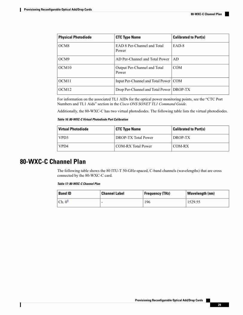
Additionally, the 80-WXC-C has two virtual photodiodes. The following table lists the virtual photodiodes.
Table 16: 80-WXC-C Virtual Photodiode Port Calibration
Calibrated to Port(s)CTC Type NameVirtual Photodiode
DROP-TXDROP-TX Total PowerVPD3
COM-RXCOM-RX Total PowerVPD4
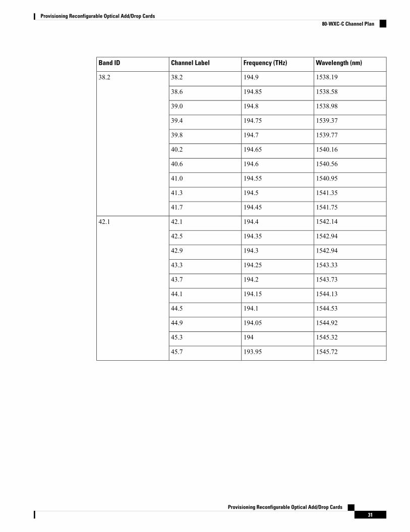
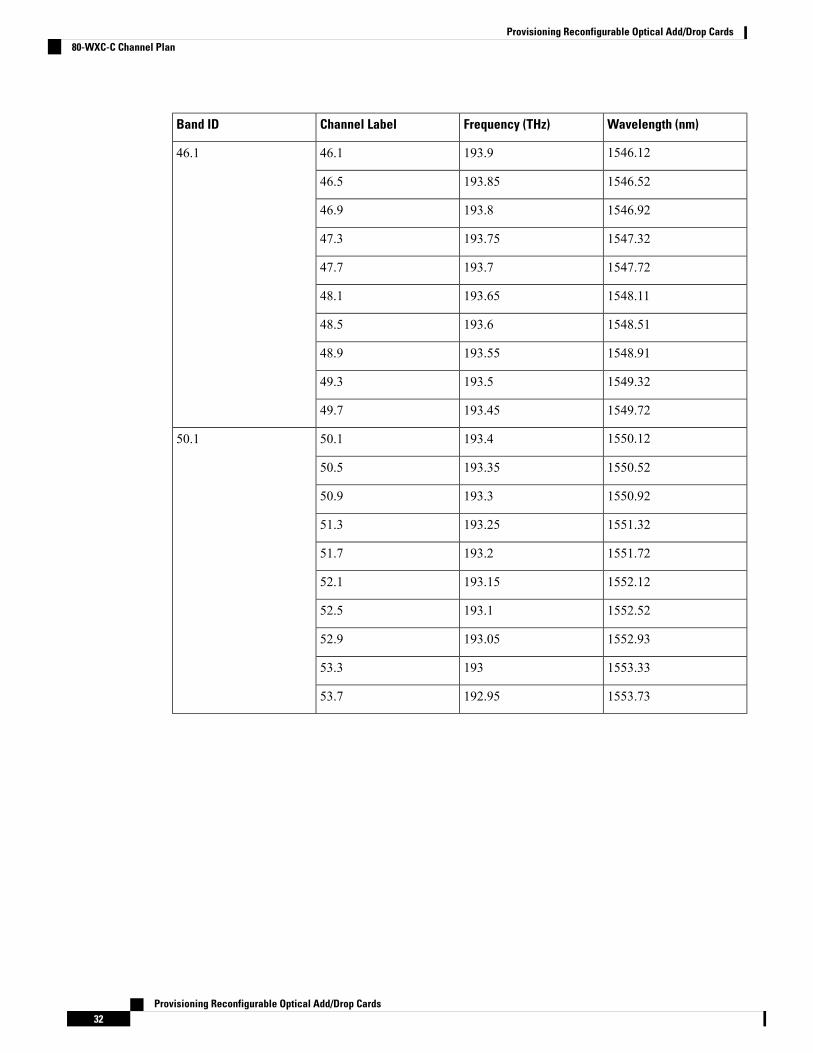
80-WXC-C Channel PlanThe following table shows the 80 ITU-T 50-GHz-spaced, C-band channels (wavelengths) that are crossconnected by the 80-WXC-C card.
Table 17: 80-WXC-C Channel Plan
Wavelength (nm)Frequency (THz)Channel LabelBand ID
1529.55196-Ch. 06
Provisioning Reconfigurable Optical Add/Drop Cards29
Provisioning Reconfigurable Optical Add/Drop Cards80-WXC-C Channel Plan

Wavelength (nm)Frequency (THz)Channel LabelBand ID
1530.33195.930.330.3
1530.72195.8530.7
1531.12195.831.1
1531.51195.7531.5
1531.90195.731.9
1532.29195.6532.3
1532.68195.632.7
1533.07195.5533.1
1533.47195.533.5
1533.86195.4533.9
1534.25195.434.334.3
1534.64195.3534.6
1535.04195.335.0
1535.43195.2535.4
1535.82195.235.8
1536.22195.1536.2
1536.61195.136.6
1537195.0537.0
1537.4019537.4
1537.79194.9537.8
Provisioning Reconfigurable Optical Add/Drop Cards30
Provisioning Reconfigurable Optical Add/Drop Cards80-WXC-C Channel Plan
Wavelength (nm)Frequency (THz)Channel LabelBand ID
1538.19194.938.238.2
1538.58194.8538.6
1538.98194.839.0
1539.37194.7539.4
1539.77194.739.8
1540.16194.6540.2
1540.56194.640.6
1540.95194.5541.0
1541.35194.541.3
1541.75194.4541.7
1542.14194.442.142.1
1542.94194.3542.5
1542.94194.342.9
1543.33194.2543.3
1543.73194.243.7
1544.13194.1544.1
1544.53194.144.5
1544.92194.0544.9
1545.3219445.3
1545.72193.9545.7
Provisioning Reconfigurable Optical Add/Drop Cards31
Provisioning Reconfigurable Optical Add/Drop Cards80-WXC-C Channel Plan
Wavelength (nm)Frequency (THz)Channel LabelBand ID
1546.12193.946.146.1
1546.52193.8546.5
1546.92193.846.9
1547.32193.7547.3
1547.72193.747.7
1548.11193.6548.1
1548.51193.648.5
1548.91193.5548.9
1549.32193.549.3
1549.72193.4549.7
1550.12193.450.150.1
1550.52193.3550.5
1550.92193.350.9
1551.32193.2551.3
1551.72193.251.7
1552.12193.1552.1
1552.52193.152.5
1552.93193.0552.9
1553.3319353.3
1553.73192.9553.7
Provisioning Reconfigurable Optical Add/Drop Cards32
Provisioning Reconfigurable Optical Add/Drop Cards80-WXC-C Channel Plan
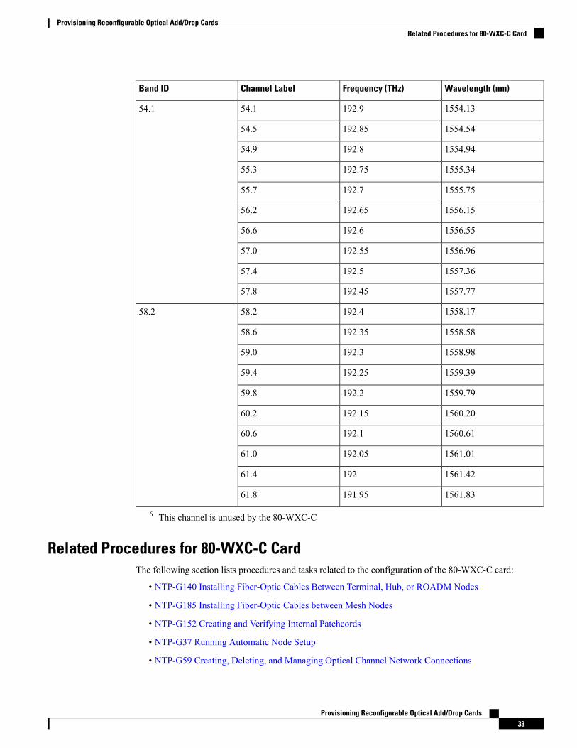
Wavelength (nm)Frequency (THz)Channel LabelBand ID
1554.13192.954.154.1
1554.54192.8554.5
1554.94192.854.9
1555.34192.7555.3
1555.75192.755.7
1556.15192.6556.2
1556.55192.656.6
1556.96192.5557.0
1557.36192.557.4
1557.77192.4557.8
1558.17192.458.258.2
1558.58192.3558.6
1558.98192.359.0
1559.39192.2559.4
1559.79192.259.8
1560.20192.1560.2
1560.61192.160.6
1561.01192.0561.0
1561.4219261.4
1561.83191.9561.8
6 This channel is unused by the 80-WXC-C
Related Procedures for 80-WXC-C CardThe following section lists procedures and tasks related to the configuration of the 80-WXC-C card:
• NTP-G140 Installing Fiber-Optic Cables Between Terminal, Hub, or ROADM Nodes
• NTP-G185 Installing Fiber-Optic Cables between Mesh Nodes
• NTP-G152 Creating and Verifying Internal Patchcords
• NTP-G37 Running Automatic Node Setup
• NTP-G59 Creating, Deleting, and Managing Optical Channel Network Connections
Provisioning Reconfigurable Optical Add/Drop Cards33
Provisioning Reconfigurable Optical Add/Drop CardsRelated Procedures for 80-WXC-C Card
• NTP-G51 Verify DWDM Node Turn Up
• DLP-G141 View Optical Power Statistics for 32MUX-O, 32WSS, 32WSS-L, 32DMX-O, 32DMX,32DMX-L, 40-WSS-C, 40-WSS-CE, 40-WXC-C, 80-WXC-C, 16-WXC-FS, 40-MUX-C, 40-DMX-C,and 40-DMX-CE Cards
• NTP-G174 Modifying Line Settings and PM Thresholds for 40-WXC-C, 80-WXC-C, or 16-WXC-FSCards
16-WXC-FS CardThe 16-WXC-FS card is a double-slot cross connect card, tunable over 96 channels in the C-band, at 50-GHzspacing on the ITU-T grid. The card provides the flex spectrum capability, which allows the user the flexibilityto allocate the channel bandwidth, to increase the network scalability. The channel bandwidth is not fixed,but can be defined arbitrarily, with a given granularity and within a given range. Attenuation and power valuesare defined for each sub-range. The central frequency ranges from 191'350 Ghz (1566 .72 nm) to 196'100Ghz (1528 .77 nm).
The 16-WXC-FS card can be used in point-to-point, ring, multi-ring, or mesh topologies. The 16-WXC-FScard supports up to 16 directions for each ROADMnode. The card is optically passive and provides bidirectionalcapability. It can be installed in slots 2, 4, or 6 in the Cisco ONS 15454 M6 chassis. It is recommended thatyou use the 16-WXC-FS card in slot 4 when used with EDRA amplifiers to comply with optical safety. It isrecommended that you use the 16-WXC-FS card and the EDRA-2-xx card in slots 2 and 4, 5 and 7, 8 and 10,11 and 13 of the Cisco ONS 15454 M15 chassis.
In the Cisco ONS 15454 M6 chassis, the 16-WXC-FS card front panel has two compression latch devices.These latches enforce the position of the unit in the chassis. To insert or remove a card from the Cisco ONS15454M6 chassis, rotate the compression latches fully in the anti-clockwise direction. After the card is insertedor removed, close the unit and rotate the compression latches fully in the clockwise direction.
Important
For more information about the 16-WXC-FS card, see http://www.cisco.com/en/US/solutions/collateral/ns340/ns394/ns398/ns406/data_sheet_c78-729313.html
Limitations
• The 16-WXC-FS card is not compatible with 15454 -M6-FTA fan tray assembly; the card is compatiblewith 15454 -M6-FTA2 fan tray assembly or a subsequent fan tray assembly release.
16-WXC-FS PortsThe 16-WXC-FS card has these ports:
• EXP-TXi (where i = 1 to 16)—The EXP TX port sends the split-off optical signal that containspass-through channels to the other side of the NE. For example, in four degrees setup, the EXP ports canbe used as drop Tx ports, EXP-Tx(1 to 4) are used as express channel from one side to other side. The5th to 16th EXP-Tx ports are used to transmit the power to passive units.
• EXP-RXi (where i = 1 to 16)—The EXP RX port receives the optical signal from the pass-throughchannels. For example, in four degrees setup, the EXP ports can be used as drop Rx ports, EXP-Rx(1 to
Provisioning Reconfigurable Optical Add/Drop Cards34
Provisioning Reconfigurable Optical Add/Drop Cards16-WXC-FS Card
4) are used to receive power from the express channel from one side to other. The 5th to 16th EXP-Rxports are used to receive the power from the passive units.
• COM-TX—The COM TX port transmits the combined power from all directions or add drop portstowards the amplifier card.
• COM-RX—The COM RX port receives the optical signal from a preamplifier card and sends it to theoptical cross connect.
• UPG-TX—The UPG TX port can be used to drop channels and transmits power to the preamplifier card.This port can also be used to increase the number of ports by connecting to another 16-WXC-FS card.
• UPG-RX-The UPG RX port can be used to add channels and receives power from the preamamplifercard. This port can also be used to increase the number of ports by connecting to another 16-WXC-FScard.
Two LC-duplex adapters are required to connect COM and UPG ports, and four MPO connectors to connectadd/drop ports of the 16-WXC card. All the 16 I/O ports of the 16-WXC-FS card can be used either for nodeinterconnection or for add/drop.
Key FeaturesThe 16-WXC-FS card provides these features when used in multiplexer mode:
• The card allows you to select a single 50-GHz spaced channel or any combination of the aggregated 96channels grid on the COM-TX port.
• The combination of input signals from the 16 EXP-RX ports and the UPG-RX port into COM-TX port.
• The selection of an arbitrary wavelength range or different wavelength ranges, with a common insertionloss value on the COM-TX port.
• Automatic VOA shutdown (AVS) blocking state on each wavelength on the COM-TX port.
• Per-channel (closed loop) power regulation on the COM-TX output port based on OCM block feedback.
• Per-channel (open loop) attenuation regulation on the EXP-TX output port, which is not based on theOCM feedback.
The 16-WXC-FS card provides these features when used in de-multiplexer mode:
• The card allows you to select a single 50-GHz spaced channel or any combination of the aggregated 96channels grid on any of the 16 EXP-TX port.
• Splitting of the input signal from COM-RX port into a total of 16 EXP-TX ports and 1 UPG-TX port.
• AVS blocking state on each wavelength on any of the 16 EXP-TX ports.
• Per-channel (closed loop) power regulation on the EXP-TX output port based on OCM block feedback.
• Per-channel (open loop) attenuation regulation on the EXP-TX output port which is not based on theOCM feedback.
• Selection of an arbitrary wavelength range or of different wavelength ranges, with a common insertionloss value on any of the 16 EXP-TX ports.
Provisioning Reconfigurable Optical Add/Drop Cards35
Provisioning Reconfigurable Optical Add/Drop CardsKey Features
• DWDM Optical amplifier(s) partially compensates the loss of couplers or splitters and wavelengthblockers.
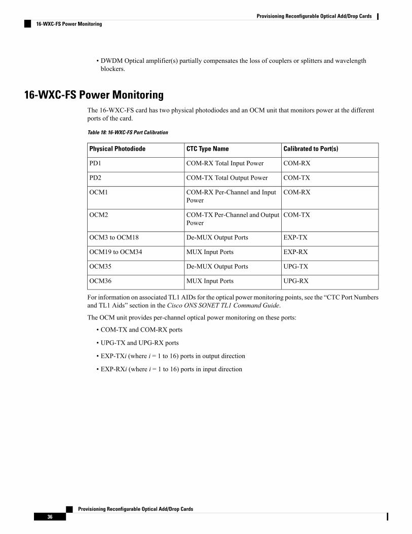
16-WXC-FS Power MonitoringThe 16-WXC-FS card has two physical photodiodes and an OCM unit that monitors power at the differentports of the card.
Table 18: 16-WXC-FS Port Calibration
Calibrated to Port(s)CTC Type NamePhysical Photodiode
COM-RXCOM-RX Total Input PowerPD1
COM-TXCOM-TX Total Output PowerPD2
COM-RXCOM-RX Per-Channel and InputPower
OCM1
COM-TXCOM-TX Per-Channel and OutputPower
OCM2
EXP-TXDe-MUX Output PortsOCM3 to OCM18
EXP-RXMUX Input PortsOCM19 to OCM34
UPG-TXDe-MUX Output PortsOCM35
UPG-RXMUX Input PortsOCM36
For information on associated TL1 AIDs for the optical power monitoring points, see the “CTC Port Numbersand TL1 Aids” section in the Cisco ONS SONET TL1 Command Guide.
The OCM unit provides per-channel optical power monitoring on these ports:
• COM-TX and COM-RX ports
• UPG-TX and UPG-RX ports
• EXP-TXi (where i = 1 to 16) ports in output direction
• EXP-RXi (where i = 1 to 16) ports in input direction
Provisioning Reconfigurable Optical Add/Drop Cards36
Provisioning Reconfigurable Optical Add/Drop Cards16-WXC-FS Power Monitoring
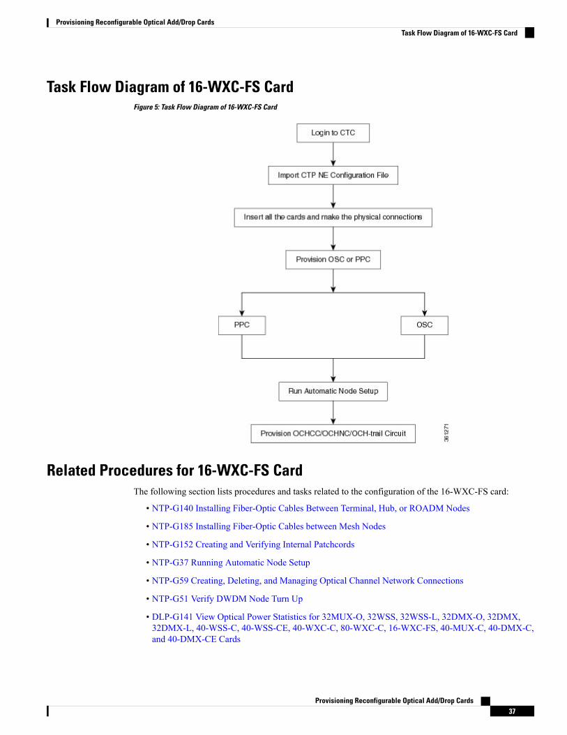
Task Flow Diagram of 16-WXC-FS CardFigure 5: Task Flow Diagram of 16-WXC-FS Card
Related Procedures for 16-WXC-FS CardThe following section lists procedures and tasks related to the configuration of the 16-WXC-FS card:
• NTP-G140 Installing Fiber-Optic Cables Between Terminal, Hub, or ROADM Nodes
• NTP-G185 Installing Fiber-Optic Cables between Mesh Nodes
• NTP-G152 Creating and Verifying Internal Patchcords
• NTP-G37 Running Automatic Node Setup
• NTP-G59 Creating, Deleting, and Managing Optical Channel Network Connections
• NTP-G51 Verify DWDM Node Turn Up
• DLP-G141 View Optical Power Statistics for 32MUX-O, 32WSS, 32WSS-L, 32DMX-O, 32DMX,32DMX-L, 40-WSS-C, 40-WSS-CE, 40-WXC-C, 80-WXC-C, 16-WXC-FS, 40-MUX-C, 40-DMX-C,and 40-DMX-CE Cards
Provisioning Reconfigurable Optical Add/Drop Cards37
Provisioning Reconfigurable Optical Add/Drop CardsTask Flow Diagram of 16-WXC-FS Card
• NTP-G174 Modifying Line Settings and PM Thresholds for 40-WXC-C, 80-WXC-C, or 16-WXC-FSCards
Single Module ROADM (SMR-C) Cards
For 40-SMR1-C and 40-SMR2-C safety label information, see the Safety Labels.Note
The single-slot 40-channel single module ROADM (SMR-C) cards integrate the following functional blocksonto a single line card:
• Optical preamplifier
• Optical booster amplifier
• Optical service channel (OSC) filter
• 2x1 wavelength cross-connect (WXC) or a 4x1 WXC
• Optical channel monitor (OCM)
The SMR-C cards are available in two versions:
• 40-SMR1-C Card
• 40-SMR2-C Card
The SMR-C cards can manage up to 40 channels spaced at 100GHz on each port according to the channelgrid in Table 10-10. The cards can be installed in Slots 1 to 6 and 12 to 17.
For more information about the 40-SMR1-C or 40-SMR2-C card, seehttp://www.cisco.com/en/US/prod/collateral/optical/ps5724/ps2006/data_sheet_c78-578552.html.
SMR-C Card Key FeaturesThe optical amplifier units in the SMR-C cards provide the following features:
• Embedded gain flattening filter
• Mid-stage access for dispersion compensation unit (only applicable for preamplifier erbium-doped fiberamplifier [EDFA])
• Fixed output power mode
• Fixed gain mode
• Nondistorting low-frequency transfer function
• Amplified spontaneous emissions (ASE) compensation in fixed gain and fixed output power mode
• Fast transient suppression
• Programmable tilt (only applicable for preamplifier EDFA)
Provisioning Reconfigurable Optical Add/Drop Cards38
Provisioning Reconfigurable Optical Add/Drop CardsSingle Module ROADM (SMR-C) Cards
• Full monitoring and alarm handling capability
• Optical safety support through signal loss detection and alarm at any input port, fast power down control,and reduced maximum output power in safe power mode.
• EDFA section calculates the signal power, by taking into account the expected ASE power contributionto the total output power. The signal output power or the signal gain can be used as feedback signals forthe EDFA pump power control loop.
The 1x2 WXC unit (40-SMR1-C card) provides the following features:
• Selection of individual wavelength of the aggregated 100GHz signal from either the EXP-RX or ADD-RXports
• Automatic VOA shutdown (AVS) blocking state on each wavelength and port
• Per-channel power regulation based on external OCM unit
• Open loop path attenuation control for each wavelength and port
The 1x4 WXC unit (40-SMR2-C card) provides the following features:
• Selection of individual wavelength of the aggregated 100GHz signal from either the EXPi-RX (where i= 1, 2, 3) or ADD-RX ports
• Automatic VOA shutdown (AVS) blocking state on each wavelength and port
• Per-channel power regulation based on external OCM unit
• Open loop path attenuation control for each wavelength and port
TheOCMunit provides per channel optical powermonitoring at EXP-RX,ADD-RX,DROP-TX, and LINE-TXports.
40-SMR1-C CardThe 40-SMR1-C card includes a 100Ghz 1x2 WXC unit with integrated preamplifier unit (single EDFA).
The 40-SMR1-C card has the following types of ports:
• MON RX: The MON RX port monitors power on the EXP-TX output port.
• MON TX: The MON TX port monitors power on the LINE-TX output port.
• DC RX: The DC RX port receives the optical signal from the dispersion compensating unit (DCU) andsends it to the second stage preamplifier input.
• DC TX: The DC TX port sends the optical signal from the first stage preamplifier output to the DCU.
• OSC RX: The OSC RX port is the OSC add input port.
• OSC TX: The OSC TX port is the OSC drop output port.
• ADD/DROP RX: The ADD RX port receives the optical signal from the multiplexer section of the NEand sends it to the 1x2 WXC unit.
• ADD/DROP TX: The DROP TX port sends the split off optical signal to the demultiplexer section ofthe NE.
Provisioning Reconfigurable Optical Add/Drop Cards39
Provisioning Reconfigurable Optical Add/Drop Cards40-SMR1-C Card
• LINE RX: The LINE RX port is the input signal port.
• LINE TX: The LINE TX port is the output signal port.
• EXP RX: The EXP RX port receives the optical signal from the other side of the NE and sends it to the1x2 WXC unit.
• EXP TX: The EXP TX port sends the split off optical signal that contains pass-through channels to theother side of the NE.
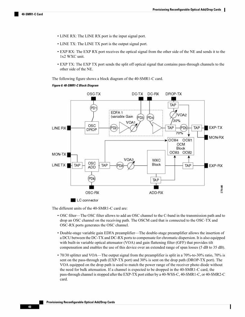
The following figure shows a block diagram of the 40-SMR1-C card.Figure 6: 40-SMR1-C Block Diagram
The different units of the 40-SMR1-C card are:
• OSC filter—The OSC filter allows to add an OSC channel to the C-band in the transmission path and todrop an OSC channel on the receiving path. The OSCM card that is connected to the OSC-TX andOSC-RX ports generates the OSC channel.
• Double-stage variable gain EDFA preamplifier—The double-stage preamplifier allows the insertion ofa DCU between the DC-TX andDC-RX ports to compensate for chromatic dispersion. It is also equippedwith built-in variable optical attenuator (VOA) and gain flattening filter (GFF) that provides tiltcompensation and enables the use of this device over an extended range of span losses (5 dB to 35 dB).
• 70/30 splitter and VOA—The output signal from the preamplifier is split in a 70%-to-30% ratio, 70% issent on the pass-through path (EXP-TX port) and 30% is sent on the drop path (DROP-TX port). TheVOA equipped on the drop path is used to match the power range of the receiver photo diode withoutthe need for bulk attenuation. If a channel is expected to be dropped in the 40-SMR1-C card, thepass-through channel is stopped after the EXP-TX port either by a 40-WSS-C, 40-SMR1-C, or 40-SMR2-Ccard.
Provisioning Reconfigurable Optical Add/Drop Cards40
Provisioning Reconfigurable Optical Add/Drop Cards40-SMR1-C Card
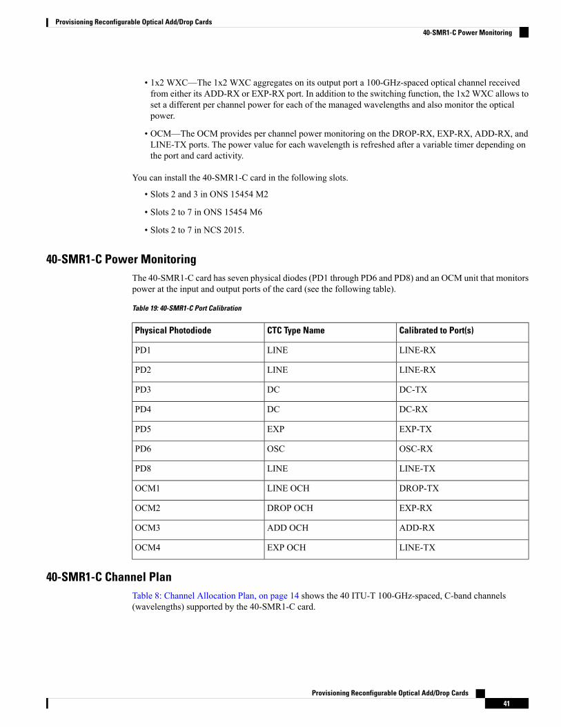
• 1x2 WXC—The 1x2 WXC aggregates on its output port a 100-GHz-spaced optical channel receivedfrom either its ADD-RX or EXP-RX port. In addition to the switching function, the 1x2 WXC allows toset a different per channel power for each of the managed wavelengths and also monitor the opticalpower.
• OCM—The OCM provides per channel power monitoring on the DROP-RX, EXP-RX, ADD-RX, andLINE-TX ports. The power value for each wavelength is refreshed after a variable timer depending onthe port and card activity.
You can install the 40-SMR1-C card in the following slots.
• Slots 2 and 3 in ONS 15454 M2
• Slots 2 to 7 in ONS 15454 M6
• Slots 2 to 7 in NCS 2015.
40-SMR1-C Power MonitoringThe 40-SMR1-C card has seven physical diodes (PD1 through PD6 and PD8) and an OCM unit that monitorspower at the input and output ports of the card (see the following table).
Table 19: 40-SMR1-C Port Calibration
Calibrated to Port(s)CTC Type NamePhysical Photodiode
LINE-RXLINEPD1
LINE-RXLINEPD2
DC-TXDCPD3
DC-RXDCPD4
EXP-TXEXPPD5
OSC-RXOSCPD6
LINE-TXLINEPD8
DROP-TXLINE OCHOCM1
EXP-RXDROP OCHOCM2
ADD-RXADD OCHOCM3
LINE-TXEXP OCHOCM4
40-SMR1-C Channel PlanTable 8: Channel Allocation Plan, on page 14 shows the 40 ITU-T 100-GHz-spaced, C-band channels(wavelengths) supported by the 40-SMR1-C card.
Provisioning Reconfigurable Optical Add/Drop Cards41
Provisioning Reconfigurable Optical Add/Drop Cards40-SMR1-C Power Monitoring
40-SMR2-C CardThe 40-SMR2-C card includes a 100Ghz 1x4 WXC unit with integrated preamplifier and booster amplifierunits (double EDFA).
The 40-SMR2-C card has the following types of ports:
• MON RX: The MON RX port monitors power on the EXP-TX output port.
• MON TX: The MON TX port monitors power on the LINE-TX output port.
• DC RX: The DC RX port receives the optical signal from the dispersion compensating unit (DCU) andsends it to the second stage preamplifier input.
• DC TX: The DC TX port sends the optical signal from the first stage preamplifier output to the DCU.
• OSC RX: The OSC RX port is the OSC add input port.
• OSC TX: The OSC TX port is the OSC drop output port.
• ADD/DROP RX: The ADD RX port receives the optical signal from the multiplexer section of the NEand sends it to the 1x4 WXC unit.
• ADD/DROP TX: The DROP TX port sends the split off optical signal to the demultiplexer section ofthe NE.
• LINE RX: The LINE RX port is the input signal port.
• LINE TX: The LINE TX port is the output signal port.
• EXP TX: The EXP TX port sends the split off optical signal that contains pass-through channels to theother side of the NE.
• EXPi-RX (where i = 1, 2, 3): The EXPi-RX port receives the optical signal from the other side of theNE and sends it to the 1x4 WXC unit.
The following figure shows a block diagram of the 40-SMR2-C card.
Provisioning Reconfigurable Optical Add/Drop Cards42
Provisioning Reconfigurable Optical Add/Drop Cards40-SMR2-C Card
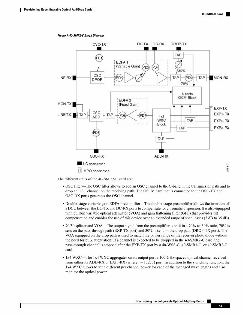
Figure 7: 40-SMR2-C Block Diagram
The different units of the 40-SMR2-C card are:
• OSC filter—The OSC filter allows to add an OSC channel to the C-band in the transmission path and todrop an OSC channel on the receiving path. The OSCM card that is connected to the OSC-TX andOSC-RX ports generates the OSC channel.
• Double-stage variable gain EDFA preamplifier—The double-stage preamplifier allows the insertion ofa DCU between the DC-TX andDC-RX ports to compensate for chromatic dispersion. It is also equippedwith built-in variable optical attenuator (VOA) and gain flattening filter (GFF) that provides tiltcompensation and enables the use of this device over an extended range of span losses (5 dB to 35 dB).
• 70/30 splitter and VOA—The output signal from the preamplifier is split in a 70%-to-30% ratio, 70% issent on the pass-through path (EXP-TX port) and 30% is sent on the drop path (DROP-TX port). TheVOA equipped on the drop path is used to match the power range of the receiver photo diode withoutthe need for bulk attenuation. If a channel is expected to be dropped in the 40-SMR2-C card, thepass-through channel is stopped after the EXP-TX port by a 40-WSS-C, 40-SMR1-C, or 40-SMR2-Ccard.
• 1x4 WXC—The 1x4 WXC aggregates on its output port a 100-GHz-spaced optical channel receivedfrom either its ADD-RX or EXPi-RX (where i = 1, 2, 3) port. In addition to the switching function, the1x4 WXC allows to set a different per channel power for each of the managed wavelengths and alsomonitor the optical power.
Provisioning Reconfigurable Optical Add/Drop Cards43
Provisioning Reconfigurable Optical Add/Drop Cards40-SMR2-C Card
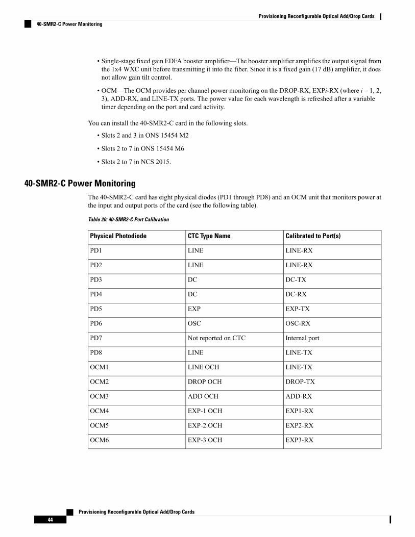
• Single-stage fixed gain EDFA booster amplifier—The booster amplifier amplifies the output signal fromthe 1x4 WXC unit before transmitting it into the fiber. Since it is a fixed gain (17 dB) amplifier, it doesnot allow gain tilt control.
• OCM—The OCM provides per channel power monitoring on the DROP-RX, EXPi-RX (where i = 1, 2,3), ADD-RX, and LINE-TX ports. The power value for each wavelength is refreshed after a variabletimer depending on the port and card activity.
You can install the 40-SMR2-C card in the following slots.
• Slots 2 and 3 in ONS 15454 M2
• Slots 2 to 7 in ONS 15454 M6
• Slots 2 to 7 in NCS 2015.
40-SMR2-C Power MonitoringThe 40-SMR2-C card has eight physical diodes (PD1 through PD8) and an OCM unit that monitors power atthe input and output ports of the card (see the following table).
Table 20: 40-SMR2-C Port Calibration
Calibrated to Port(s)CTC Type NamePhysical Photodiode
LINE-RXLINEPD1
LINE-RXLINEPD2
DC-TXDCPD3
DC-RXDCPD4
EXP-TXEXPPD5
OSC-RXOSCPD6
Internal portNot reported on CTCPD7
LINE-TXLINEPD8
LINE-TXLINE OCHOCM1
DROP-TXDROP OCHOCM2
ADD-RXADD OCHOCM3
EXP1-RXEXP-1 OCHOCM4
EXP2-RXEXP-2 OCHOCM5
EXP3-RXEXP-3 OCHOCM6
Provisioning Reconfigurable Optical Add/Drop Cards44
Provisioning Reconfigurable Optical Add/Drop Cards40-SMR2-C Power Monitoring

40-SMR2-C Channel PlanTable 8: Channel Allocation Plan, on page 14 shows the 40 ITU-T 100-GHz-spaced, C-band channels(wavelengths) supported by the 40-SMR2-C card.
Related Procedures for 40-SMR1-C and 40-SMR2-C CardThe following section lists procedures and tasks related to the configuration of the 40-SMR-1C and 40-SMR-2Ccards:
• NTP-G140 Installing Fiber-Optic Cables Between Terminal, Hub, or ROADM Nodes
• NTP-G185 Installing Fiber-Optic Cables between Mesh Nodes
• NTP-G152 Creating and Verifying Internal Patchcords
• NTP-G37 Running Automatic Node Setup
• NTP-G243 Performing the Two-Degree ROADM Node with 40-SMR-1-C and OPT-AMP-17-C CardsAcceptance Test
• NTP-G244 Performing the Four Degree ROADM Node with 40-SMR-2-C Cards Acceptance Test
• NTP-G59 Creating, Deleting, and Managing Optical Channel Network Connections
• NTP-G51 Verify DWDM Node Turn Up
• DLP-G141 View Optical Power Statistics for 32MUX-O, 32WSS, 32WSS-L, 32DMX-O, 32DMX,32DMX-L, 40-WSS-C, 40-WSS-CE, 40-WXC-C, 80-WXC-C, 16-WXC-FS, 40-MUX-C, 40-DMX-C,and 40-DMX-CE Cards
• NTP-G241 Modifying the Line Settings and PM Thresholds for 40-SMR1-C and 40-SMR2-C Cards
17 SMR9 FS, 24 SMR9 FS, 34 SMR9 FS, and SMR20 FS/SMR20 FS CV CardsThe 17 SMR9 FS, 24 SMR9 FS, 34 SMR9 FS, and SMR20 FS/SMR20 FS CV cards are tunable over 96channels in the C-band, at 50-GHz spacing on the ITU-T grid. The cards provide the flex spectrum capability,which give the flexibility to allocate channel bandwidth, to increase the network scalability. The channelbandwidth is not fixed, but can be defined arbitrarily, with a specified granularity and within a given range.For each sub-range, attenuation and power values are defined. The central frequency ranges from 191350Ghz (1566 .72 nm) to 196100 Ghz (1528 .77 nm).
The 17 SMR9 FS, 24 SMR9 FS, 34 SMR9 FS, and SMR20 FS/SMR20 FS CV cards are single-slot cards thatintegrate two cross-connect blocks (multiplexer and demultiplexer), a variable gain EDFA pre-amplifier, anda variable gain EDFA booster amplifier. In addition, the SMR20 FS CV card has a dedicated laser source atthe demultiplexer section, and a photodiode at the multiplexer section; these support the connection verificationcapability. The 17 SMR9 FS, 24 SMR9 FS, and 34 SMR9 FS cards support up to 9 directions for each ROADMnode. The SMR20 FS/SMR20 FS CV card support up to 20 directions for each ROADM node. The cards canbe installed in any service slot in the Cisco ONS 15454 M2, ONS 15454 M6, and the NCS 2015 chassis. Thecards can be used in point-to-point, ring, multi-ring, or mesh topologies.
The SMR20 FS CV cards provide the connection verification capability using a connectivity check signal.The correctness and the quality of the interconnections (determined by measuring the insertion loss of theexternal passive path) can be validated with the connection verification feature in the cards . For moreinformation about the connection verification, see Connection Verification section.
Provisioning Reconfigurable Optical Add/Drop Cards45
Provisioning Reconfigurable Optical Add/Drop Cards40-SMR2-C Channel Plan
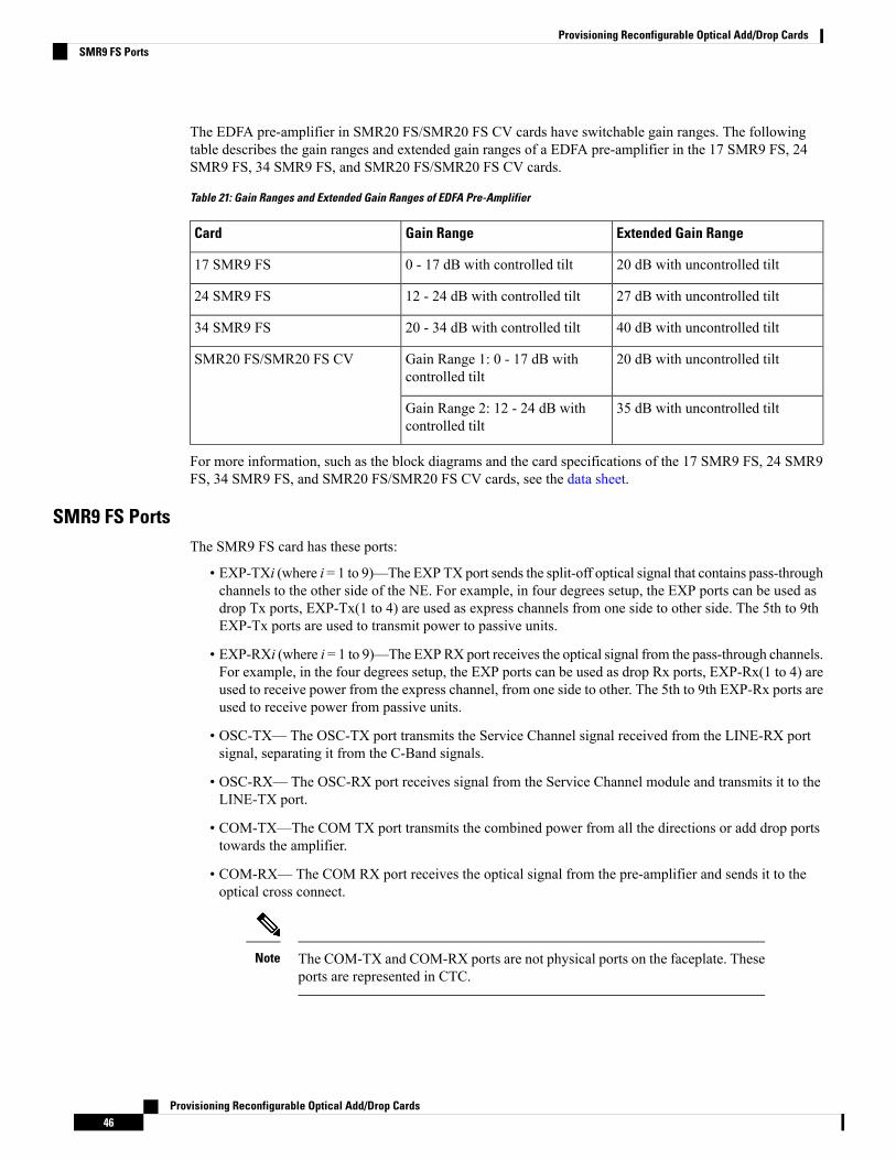
The EDFA pre-amplifier in SMR20 FS/SMR20 FS CV cards have switchable gain ranges. The followingtable describes the gain ranges and extended gain ranges of a EDFA pre-amplifier in the 17 SMR9 FS, 24SMR9 FS, 34 SMR9 FS, and SMR20 FS/SMR20 FS CV cards.
Table 21: Gain Ranges and Extended Gain Ranges of EDFA Pre-Amplifier
Extended Gain RangeGain RangeCard
20 dB with uncontrolled tilt0 - 17 dB with controlled tilt17 SMR9 FS
27 dB with uncontrolled tilt12 - 24 dB with controlled tilt24 SMR9 FS
40 dB with uncontrolled tilt20 - 34 dB with controlled tilt34 SMR9 FS
20 dB with uncontrolled tiltGain Range 1: 0 - 17 dB withcontrolled tilt
SMR20 FS/SMR20 FS CV
35 dB with uncontrolled tiltGain Range 2: 12 - 24 dB withcontrolled tilt
For more information, such as the block diagrams and the card specifications of the 17 SMR9 FS, 24 SMR9FS, 34 SMR9 FS, and SMR20 FS/SMR20 FS CV cards, see the data sheet.
SMR9 FS PortsThe SMR9 FS card has these ports:
• EXP-TXi (where i = 1 to 9)—The EXP TX port sends the split-off optical signal that contains pass-throughchannels to the other side of the NE. For example, in four degrees setup, the EXP ports can be used asdrop Tx ports, EXP-Tx(1 to 4) are used as express channels from one side to other side. The 5th to 9thEXP-Tx ports are used to transmit power to passive units.
• EXP-RXi (where i = 1 to 9)—The EXPRX port receives the optical signal from the pass-through channels.For example, in the four degrees setup, the EXP ports can be used as drop Rx ports, EXP-Rx(1 to 4) areused to receive power from the express channel, from one side to other. The 5th to 9th EXP-Rx ports areused to receive power from passive units.
• OSC-TX— The OSC-TX port transmits the Service Channel signal received from the LINE-RX portsignal, separating it from the C-Band signals.
• OSC-RX— The OSC-RX port receives signal from the Service Channel module and transmits it to theLINE-TX port.
• COM-TX—The COM TX port transmits the combined power from all the directions or add drop portstowards the amplifier.
• COM-RX— The COM RX port receives the optical signal from the pre-amplifier and sends it to theoptical cross connect.
The COM-TX and COM-RX ports are not physical ports on the faceplate. Theseports are represented in CTC.
Note
Provisioning Reconfigurable Optical Add/Drop Cards46
Provisioning Reconfigurable Optical Add/Drop CardsSMR9 FS Ports
• LINE-TX— The booster amplifier amplifies the composite signal coming from WXC-MUX towardsthe LINE-TX port.
• LINE-RX— The pre amplifier amplifies the composite signal coming from the LINE-RX port towardsthe WXC-DMX input.
SMR20 FS and SMR20 FS CV PortsThe SMR20 FS and SMR20 FS CV cards have these ports:
• EXP-TXi (where i = 1 to 20)—The EXP TX port sends the split-off optical signal that containspass-through channels to the other side of the NE. For example, in the four degrees setup, the EXP portscan be used as drop Tx ports; EXP-Tx(1 to 4) are used as express channel from one side to other side.The 5th to 20th EXP-Tx ports are used to transmit power to passive units.
• EXP-RXi (where i = 1 to 20)—The EXP RX port receives the optical signal from the pass-throughchannels. For example, in the four degrees setup, the EXP ports can be used as add Rx ports, EXP-Rx(1to 4) are used to receive power from the express channels from one side to other. The 5th to 20th EXP-Rxports are used to receive power from passive units.
• OSC-TX— The OSC-TX port transmits the Service Channel signal received from the LINE-RX portsignal, separating it from the C-Band signals.
• OSC-RX— The OSC-RX port receives signal from the Service Channel module and transmits it to theLINE-TX port.
• COM-TX—The COM TX port transmits the combined power from all the directions or add drop portstowards the booster amplifier.
• COM-RX— The COM RX port receives the optical signal from the pre-amplifier and sends it to theoptical cross connect.
The COM-TX and COM-RX ports are not physical ports on the faceplate. Theseports are represented in CTC.
Note
• LINE-TX— The booster amplifier amplifies the composite signal coming from WXC-MUX towardsthe LINE-TX port.
• LINE-RX— The pre amplifier amplifies the composite signal coming from the LINE-RX port towardsthe WXC-DMX input.
Key FeaturesThe multiplexer section of the 17 SMR9 FS, 24 SMR9 FS, 34 SMR9 FS, and SMR20 FS/SMR20 FS CVcards provide the following features:
• Selection of any arbitrary wavelength range from any EXP-RXi ports and routing to MUX output port.
• Automatic VOA shutdown (AVS) blocking state on each wavelength on the MUX output port.
• Per-channel (closed loop) power regulation on the MUX output port based on OCM block feedback.
Provisioning Reconfigurable Optical Add/Drop Cards47
Provisioning Reconfigurable Optical Add/Drop CardsSMR20 FS and SMR20 FS CV Ports
• Per-channel (open loop) attenuation regulation on the MUX output port, which is not based on the OCMfeedback.
• Amplification of the aggregated C-Band signal towards the LINE-TX port by the variable gain boosterEDFA amplifier.
• Combination of C-Band signals with 1510 nm by OSC MUX filter.
• Detection of the connectivity check signal, of wavelength 97 nm, by an embedded photodiode.
The demultiplexer section of the 17 SMR9 FS, 24 SMR9 FS, 34 SMR9 FS, and SMR20 FS/SMR20 FS CVcards provide the following features:
• Selection of any arbitrary wavelength range and routing to any EXP-TXi port.
• AVS blocking state on each wavelength, on any of the EXP-TXi ports.
• Per-channel (closed loop) power regulation on the EXP-TXi output port based on OCM block feedback.
• Per-channel (open loop) attenuation regulation on the EXP-TXi output port, which is not based on theOCM feedback.
• Amplification of the C-Band signals entering the LINE-RX port by the pre-amplifier.
• Separation of C-Band signals from 1510 nm by OSC De-MUX filter.
• Generation and transmission of the connectivity check signal into the DE-MUX input port.
The 17 SMR9 FS, 24 SMR9 FS, 34 SMR9 FS, and SMR20 FS cards also support count-based licensing. Formore information on licensing, see the Cisco ONS 15454 DWDM Licensing Configuration Guide.
Connection VerificationThe SMR20 FS CV cards provide the connection verification feature. This feature measures power levels andverifies the optical cables and patchcords in a node for:
• Connectivity: Checks whether the cable is connected.
• Insertion Loss: Checks whether the cable loss is within expected value.
A 1567 nm connectivity check signal is generated and transmitted into the DE-MUX input port by a dedicatedlaser source. This signal, in turn, is detected by an embedded photo diode to complete the verification. Thehighlights of this feature are:
• It validates the SMR20 FS CV card connection with other nodes or local Add/Drop elements.
• It detects any incorrect cabling of the ROADM network element.
• It collects insertion losses of every possible optical path inside the network element, in order to predictany possible failure.
• It verifies the connection every six hours, by default. Refer to http://www.cisco.com/c/en/us/td/docs/optical/15000r10_0/ncs/network_config/guide/b_ncs_network_configuration/b_ncs_network_configuration_chapter_010000.html#task_8B1E0075021B4A7EBCAC85FD09C02AC8 for manualvalidation of the SMR20 FS CV interconnections.
Provisioning Reconfigurable Optical Add/Drop Cards48
Provisioning Reconfigurable Optical Add/Drop CardsConnection Verification
In releases earlier to Release 10.8, the Connection Verification (CV) procedure aborts when the CV and circuitcreation procedures that use the same wavelength, run concurrently on CV enabled cards. The wavelengththat was used for CV is then auto-provisioned due to which the circuit creation uses a different wavelength.
Note
Connection Verification PrerequisitesThe connection verification works only if the following conditions are fulfilled:
• Flex nodes must be present for the connection verification to work.
• Loopback caps must be installed on all the unused ports of the passive modules.
• At least one SMR20 FS CV card must be present in the node.
• All sides of the node must have a SMR20 FS CV card to test all cables and patchcords.
• All passive modules must be connected with an USB cable and associated, so that power readings canbe calculated.
Supported CardsThe cards that supports connection verification are as follow:
• 16-AD-FS
• SMR20 FS CV
• MF-DEG-5 and MF-DEG-5-CV
• MF-MPO-16LC and MF-MPO-16LC-CV
• MF-PPMESH8-5AD
• MF-UPG-4 and MF-UPG-4-CV
• 100GC-CK-LC and 200G-CK-LC
• Other MXP and TXP cards support CV partially; these cards support theCV for the patch cords belonging to paths going from TXP card trunk portto SMR20-FS-CV EXP-RX ports and not for the patch cords belonging topath in the opposite direction.
• MF-DEG-5, MF-DEG-5-CV, MF-MPO-16LC, MF-MPO-16LC-CV,MF-PPMESH8-5AD, MF-UPG-4, and MF-UPG-4-CV cards requireloopback caps on unused ports. The (-CV) version is shipped with theloopback pre-installed.
Note
Running the Connection VerificationThe connection verification runs:
Provisioning Reconfigurable Optical Add/Drop Cards49
Provisioning Reconfigurable Optical Add/Drop CardsConnection Verification Prerequisites

• Automatically at these time intervals and events:
• 20 minutes after first shelf controller boot or reboot
• One minute after enabling the connection verification
• Ten minutes after new patch-cord creation or deletion (*)
• Ten minutes after new circuit creation or deletion (*)
• Every six hours
• For manual execution of connection verification, refer to http://www.cisco.com/c/en/us/td/docs/optical/15000r10_0/ncs/network_config/guide/b_ncs_network_configuration/b_ncs_network_configuration_chapter_010000.html#task_8B1E0075021B4A7EBCAC85FD09C02AC8.
(*) indicates that this condition occurs only after an automatic run is interrupted by the creation or deletionof a circuit or a patch cord.
PIDs of 17 SMR9 FS, 24 SMR9 FS, 34 SMR9 FS, and SMR20 FS/SMR20 FS CV CardsThe following table lists the PIDs and descriptions of the 17 SMR9 FS, 24 SMR9 FS, 34 SMR9 FS, andSMR20 FS/SMR20 FS CV cards.
DescriptionPID
9 port Single Module ROADM - 0-17 dB Gain - Flex SpectrumNCS2K-9-SMR17FS=
9 port SingleModule ROADM - 12-24 dBGain - Flex SpectrumNCS2K-9-SMR24FS=
9 port SingleModule ROADM - 20-34 dBGain - Flex SpectrumNCS2K-9-SMR34FS=
20 port Single Module ROADM - Switchable Gain - FlexSpectrum
NCS2K-20-SMRFS=
20 port Single Module ROADM - Switchable Gain FlexSpectrum with Connection Verification
NCS2K-20-SMRFS-CV=
9 port Single Module ROADM - 0-17 dB Gain - LicensedNCS2K-9-SMR17FS-L=
9 port Single Module ROADM - 12-24 dB Gain - LicensedNCS2K-9-SMR24FS-L=
9 port Single Module ROADM - 20-34 dB Gain - LicensedNCS2K-9-SMR34FS-L=
20 port Single Module ROADM - Switchable Gain - FlexSpectrum - Licensed
NCS2K-20-SMRFS-L=
License PID to enable Flex Spectrum capability for the 17 SMR9FS, 24 SMR9 FS, 34 SMR9 FS, and SMR20 FS cards. NCSFlex package is required to use this license.
L-NCS2K-SMR-FS=
License PID to enable two EXP-TX/EXP-RX ports on the 17SMR9 FS, 24 SMR9 FS, or 34 SMR9 FS cards.
L-NCS2K-SMR-2P=
License PID to enable four EXP-TX/EXP-RX ports on theSMR20 FS card.
L-NCS2K-SMR-4P=
Provisioning Reconfigurable Optical Add/Drop Cards50
Provisioning Reconfigurable Optical Add/Drop CardsPIDs of 17 SMR9 FS, 24 SMR9 FS, 34 SMR9 FS, and SMR20 FS/SMR20 FS CV Cards
Related Procedures for 17 SMR9 FS, 24 SMR9 FS, 34 SMR9 FS, and SMR20 FS/SMR20 FS CV CardsThe following section lists procedures and tasks related to the configuration of the 17 SMR9 FS, 24 SMR9FS, 34 SMR9 FS, and SMR20 FS/SMR20 FS CV cards:
• DLP-G325 Changing Optical Amplifier Line Settings
• DLP-G326 Changing Optical Amplifier Threshold Settings
• DLP-G406 Changing Card Optical Channel Parameters for 40-WXC-C, 80-WXC-C, 16-WXC-FS, 17SMR9 FS, 24 SMR9 FS, 34 SMR9 FS, SMR20 FS, or SMR20 FS CV Cards
• DLP-G407 Changing the Optical Channel Thresholds for 40-WXC-C, 80-WXC-C, 16-WXC-FS, 17SMR9 FS, 24 SMR9 FS, 34 SMR9 FS, SMR20 FS, or SMR20 FS CV Cards
• DLP-G408 Changing Optical Line Parameters for 40-WXC-C, 80-WXC-C, 16-WXC-FS, 17 SMR9 FS,24 SMR9 FS, 34 SMR9 FS, SMR20 FS, or SMR20 FS CV Cards
• DLP-G409 Changing the Optical Line Thresholds for 40-WXC-C, 80-WXC-C, 16-WXC-FS, 17 SMR9FS, 24 SMR9 FS, 34 SMR9 FS, SMR20 FS, or SMR20 FS CV Cards
• DLP-G772 Viewing Wavelength Power for 16-WXC-FS, 17 SMR9 FS, 24 SMR9 FS, 34 SMR9 FS,SMR20 FS, or SMR20 FS CV Card
• DLP-G773 Creating a Flex Spectrum or ITU Circuit for 16-WXC-FS, 17 SMR9 FS, 24 SMR9 FS, 34SMR9 FS, SMR20 FS, or SMR20 FS CV Card
• DLP-G140 View Power Statistics for Optical Amplifier, 40-SMR1-C, 40-SMR2-C, 17 SMR9 FS, 24SMR9 FS, 34 SMR9 FS, SMR20 FS, and SMR20 FS CV Cards
• DLP-G141 View Optical Power Statistics for 32MUX-O, 32WSS, 32WSS-L, 32DMX-O,32DMX,32DMX-L, 40-WSS-C, 40-WSS-CE, 40-WXC-C, 80-WXC-C, 16-WXC-FS, 17 SMR9 FS, 24 SMR9FS, 34 SMR9 FS, SMR20 FS, SMR20 FS CV, 40-MUX-C, 40-DMX-C, and 40-DMX-CE Cards
MMU Card(Cisco ONS 15454 only)
The single-slot Mesh Multi-Ring Upgrade Module (MMU) card supports multiring and mesh upgrades forROADM nodes in both the C-band and the L-band. Mesh/multiring upgrade is the capability to opticallybypass a given wavelength from one section of the network or ring to another one without requiring 3Rregeneration. In each node, you need to install one east MMU and one west MMU. The card can be installedin Slots 1 through 6 and 12 through 17.
The MMU has six types of ports:
• EXP RX port: The EXP RX port receives the optical signal from the ROADM section available on theNE.
• EXP TX port: The EXP TX port sends the optical signal to the ROADM section available on the NE.
• EXP-A RX port: The EXP-A RX port receives the optical signal from the ROADM section available onother NEs or rings.
• EXP-A TX port: The EXP-A TX port sends the optical signal to the ROADM section available on otherNEs or rings.
Provisioning Reconfigurable Optical Add/Drop Cards51
Provisioning Reconfigurable Optical Add/Drop CardsRelated Procedures for 17 SMR9 FS, 24 SMR9 FS, 34 SMR9 FS, and SMR20 FS/SMR20 FS CV Cards
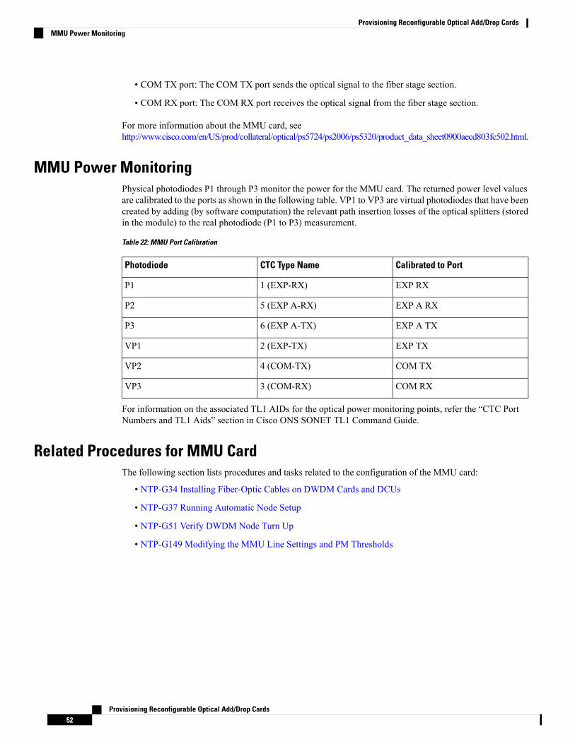
• COM TX port: The COM TX port sends the optical signal to the fiber stage section.
• COM RX port: The COM RX port receives the optical signal from the fiber stage section.
For more information about the MMU card, seehttp://www.cisco.com/en/US/prod/collateral/optical/ps5724/ps2006/ps5320/product_data_sheet0900aecd803fc502.html.
MMU Power MonitoringPhysical photodiodes P1 through P3 monitor the power for the MMU card. The returned power level valuesare calibrated to the ports as shown in the following table. VP1 to VP3 are virtual photodiodes that have beencreated by adding (by software computation) the relevant path insertion losses of the optical splitters (storedin the module) to the real photodiode (P1 to P3) measurement.
Table 22: MMU Port Calibration
Calibrated to PortCTC Type NamePhotodiode
EXP RX1 (EXP-RX)P1
EXP A RX5 (EXP A-RX)P2
EXP A TX6 (EXP A-TX)P3
EXP TX2 (EXP-TX)VP1
COM TX4 (COM-TX)VP2
COM RX3 (COM-RX)VP3
For information on the associated TL1 AIDs for the optical power monitoring points, refer the “CTC PortNumbers and TL1 Aids” section in Cisco ONS SONET TL1 Command Guide.
Related Procedures for MMU CardThe following section lists procedures and tasks related to the configuration of the MMU card:
• NTP-G34 Installing Fiber-Optic Cables on DWDM Cards and DCUs
• NTP-G37 Running Automatic Node Setup
• NTP-G51 Verify DWDM Node Turn Up
• NTP-G149 Modifying the MMU Line Settings and PM Thresholds
Provisioning Reconfigurable Optical Add/Drop Cards52
Provisioning Reconfigurable Optical Add/Drop CardsMMU Power Monitoring