
Providing Uninterrupted Power for GeneXpert® in Low and … · 6 Background Earlier and improved...
37
Providing Uninterrupted Power for GeneXpert® in Low and Middle Income Settings: A Practical Guide
Transcript of Providing Uninterrupted Power for GeneXpert® in Low and … · 6 Background Earlier and improved...
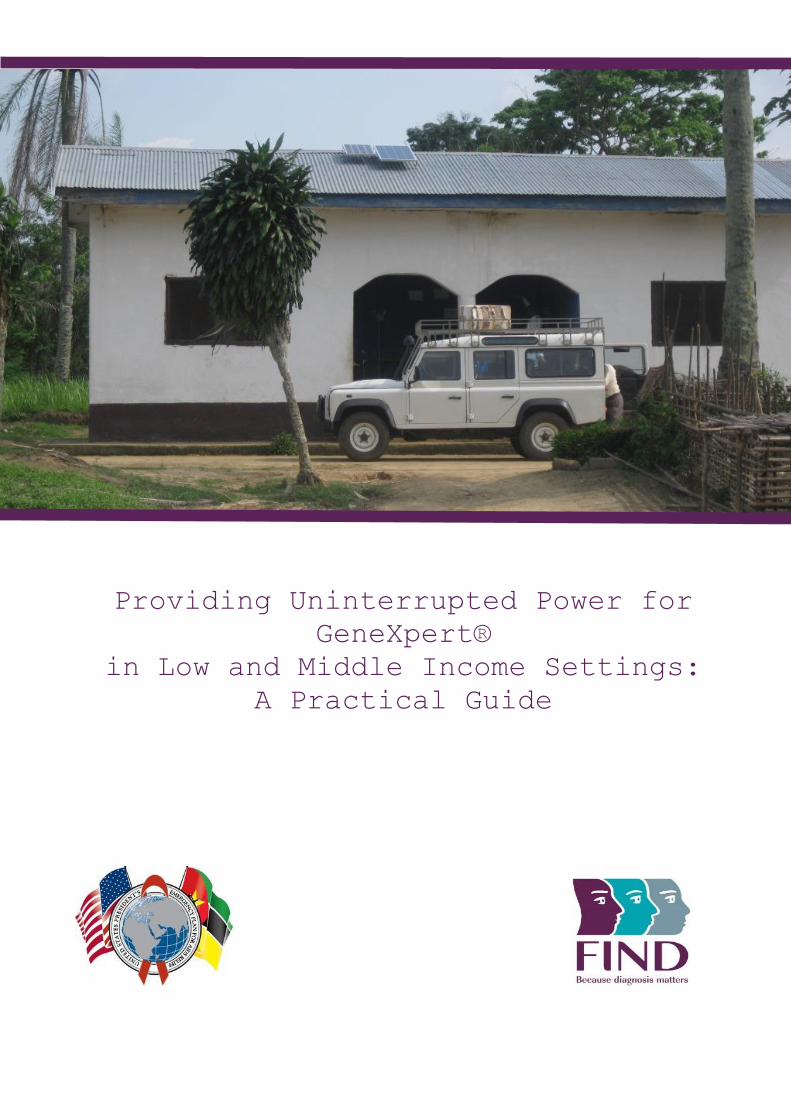
Providing Uninterrupted Power for
GeneXpert®
in Low and Middle Income Settings:
A Practical Guide
2
Table of Contents
Acknowledgements ........................................................................................................................... 3
Scope ................................................................................................................................................ 4
Target audience ......................................................................................................................... 4
Abbreviations .................................................................................................................................... 5
Background ....................................................................................................................................... 6
Status of power supply in LMICs ....................................................................................................... 7
Stepwise approach to providing uninterrupted power supply for GeneXpert ...................................... 8
Step 1: Assess the existing power supply and available backup .................................................... 8
See Annex 3 for GeneXpert pre-installation checklist – power requirements. ................................ 9
Step 2: Determine the GeneXpert facility power requirements and supply shortfall ....................... 9
Step 3: Select solution based on review of backup options ...........................................................10
Step 4: Maintenance and servicing ...............................................................................................20
References .......................................................................................................................................21
Case studies ....................................................................................................................................22
1. India: A dual approach using UPS and solar solutions at 18 GeneXpert sites ........................22
2. Myanmar: Establishment of GeneXpert laboratories at six diverse locations .........................24
3. Uganda: Utilizing solar panels to ensure uninterrupted power at two district laboratories..........25
Conclusions and recommendations..................................................................................................26
Annex 1: Power specifications for GeneXpert equipment .............................................................27
Annex 2: Backup system considerations.......................................................................................28
Batteries ....................................................................................................................................28
Power Regulators: UPS/Inverter ...............................................................................................29
Photovoltaic (PV) modules / solar panels ..................................................................................31
Generators ................................................................................................................................31
Annex 3: GeneXpert pre-installation checklist – power requirements ............................................33
Annex 4: Field scenario details .....................................................................................................36
Cost analysis ................................................................................................................................37

3
Acknowledgements
This work has been supported by the President’s Emergency Plan for AIDS Relief (PEPFAR) Mozambique through the U.S. Centers for Disease Control and Prevention (CDC). The findings and conclusions in this article are those of the authors and do not necessarily represent the official position of the CDC.
Use of trade names is for identification purposes only and does not constitute endorsement by the CDC.
We acknowledge, with thanks, the following people who contributed to the development of this guide (in alphabetical order): Heather Alexander (US Centers for Disease Control and Prevention), Jessica Bennett (FIND Geneva), Catharina Boehme (FIND Geneva), Michael Cooke (IHS Consultations), C.N. Paramasivan (FIND India), Neeraj Raizada (FIND India), Tarak Shah (FIND India), TiTi (Laboratory consultant, Yangon, Myanmar), Manoj Toshniwal (FIND India), Roslyn Twidale (Talent and Technology, Yangon, Myanmar). Lead writers: Heidi Albert (FIND South Africa), Umesh Alavadi (FIND India). Lead reviewers: Khushabu Paliwal (FIND India), André Trollip (FIND South Africa), Priyank Verma (FIND India), and Naga Vigneshwaran PS (FIND India).
4
Scope
The Xpert MTB/RIF® assay has been endorsed by the World Health Organization (WHO) for use in low and middle income countries for the rapid detection and drug resistance testing of Mycobacterium tuberculosis. Although the test can be performed at peripheral facilities, the availability of a continuous stable power supply is critical in ensuring optimal utilization of this technology. Many of the settings at decentralized levels of the health system in high TB burden countries have constraints with electricity supply in terms of both continuity and voltage stability. The time taken for an Xpert MTB/RIF test run to be completed is approximately two hours. Therefore, to support the GeneXpert® instrument, a suitable system must supply uninterrupted power for at least the testing duration and for a longer duration (up to 8 hours) in order to ensure same day testing and reporting within laboratory working hours. Although the manufacturer has clearly stated the power requirements of the different capacity GeneXpert instruments, how to meet these in different electricity supply scenarios has remained a challenge for many involved in implementation of this technology. Appropriate solutions to the problem of power outages vary depending on the duration and timings of main grid supply and incidence of outages. Several countries have reported backup solutions ranging from custom-made battery arrays with a power inverter to solar-power installations.
Target audience
This document is intended to provide clear guidance on GeneXpert power backup solutions to meet different power supply scenarios. The document is aimed at laboratory managers, programme managers, local and international partners and donors, and provides an analysis of various solutions which may be employed to provide uninterrupted power in different field situations, along with estimation of cost, installation and maintenance requirements. This document is intended to guide the selection of appropriate uninterrupted power supply (UPS) solutions and to inform planning and budgeting processes. It is not intended to replace the need for local specialist advice regarding procurement and appropriate installation and maintenance of power back up solutions.
5
Abbreviations
AC Alternating current
AGM Absorbed glass mat
AH Ampere hours
CBNAAT Cartridge-Based Nucleic Acid Amplification Test
CDC U.S. Centers for Disease Control and Prevention
DOD Depth of discharge
DR Drug resistance
FIND Foundation for Innovative New Diagnostics
GeneXpert® Instrument platform for performing Xpert MTB/RIF® test
GX–IV R2 Four module GeneXpert instrument
IEA International Energy Agency
IEC International Electrotechnical Commission
LED-FM Light emitting diode - fluorescence microscopy
LMIC Low and middle income countries
MCB Main circuit breaker
MTB Mycobacterium tuberculosis
NAAT Nucleic acid amplification test
NTLP National Tuberculosis and Leprosy Control Programme
OECD Organization for Economic Co-operation and Development
PV modules Photovoltaic modules / Solar panels
TB Tuberculosis
UPS Uninterrupted power supply
W Watt, unit of power
WHO World Health Organization
6
Background Earlier and improved detection of all types of tuberculosis (TB) is a global priority for TB control. The Xpert MTB/RIF® assay for the GeneXpert® platform was endorsed by WHO in 2010 for use in low and middle income countries for the rapid detection of TB and identification of rifampicin resistance(1). It is considered as an important breakthrough in the fight against TB. For the first time, a molecular test became available which is simple and robust enough to be used outside sophisticated, centralized laboratory settings. Xpert MTB/RIF detects the presence of M. tuberculosis complex as well as common mutations that confer rifampicin resistance in biological specimens. In addition to the WHO policy guidance document, a rapid implementation manual was published, which provided the technical “how-to” and operational considerations for rolling out the assay; the document also provided a simple checklist of pre-requisites necessary for implementation (2). Successful deployment of this technology has been reported through peer-reviewed publications, systematic reviews, and also in reports from country and technical partners during implementers meetings. In October 2013, WHO issued updated policy guidance, providing revised recommendations on using Xpert MTB/RIF to diagnose pulmonary TB, paediatric TB, extra pulmonary TB and rifampicin resistance (3). The Xpert MTB/RIF test has similar biosafety requirements to those for direct smear microscopy, enabling placement of the system at lower level health facilities, such as at district or sub-district level. While this should theoretically improve access to testing, decentralization comes with a number of challenges (4). One such challenge is the requirement of an uninterrupted supply of stable electricity, which is essential for GeneXpert instrument operation. The Xpert MTB/RIF assay takes 2 hours running time once the test cartridge has been loaded into the instrument. Should electricity supply be interrupted during the running of a test, results are lost, reagents wasted, and it will be necessary to obtain another sample from patients, thereby delaying diagnosis. Repeated interruptions in power may lead to possible damage to or failure of the modules. Xpert MTB/RIF cartridges require storage at between 2 and 28°C and therefore in hot climates, this requires constant power for air conditioning units to maintain this temperature range. Similarly, the equipment should be kept at between 15 and 30°C. Electricity is also required for prompt electronic reporting of results in programmatic settings. Not only is the continuity of electrical supply critical, stability of the voltage range is also important. An unstable supply of electricity may damage the electronics of the instrument and the computer, which may not be covered by the manufacturer’s warranty. These considerations may limit positioning the instrument further down in the tiered health structure and affect the rapid turnaround around time. Establishing Xpert MTB/RIF testing capacity at higher levels of the health system involves some additional time for specimen transportation and reporting of results to the peripheral health workers and patients. Ensuring power backup for one test run is an option exercised in many settings, where infrequent and short interruptions in power are experienced. However, this option may be inadequate in some settings, especially where more frequent and/or longer duration power interruptions occur. In such cases, samples may remain untested, leading to back logs in testing and continuous delay in providing test results. Stable power is required not only for the GeneXpert instrument but also for a printer, computer and internet modem. Without these working, rapid reporting of results to clinicians and thus early initiation of appropriate treatment are not possible.
7
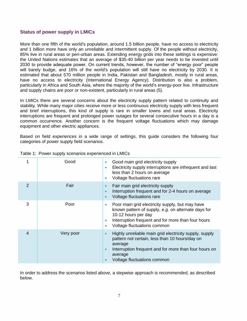
Status of power supply in LMICs
More than one fifth of the world's population, around 1.5 billion people, have no access to electricity and 1 billion more have only an unreliable and intermittent supply. Of the people without electricity, 85% live in rural areas or peri-urban areas. Extending energy grids into these settings is expensive: the United Nations estimates that an average of $35-40 billion per year needs to be invested until 2030 to provide adequate power. On current trends, however, the number of “energy poor” people will barely budge, and 16% of the world's population will still have no electricity by 2030. It is estimated that about 570 million people in India, Pakistan and Bangladesh, mostly in rural areas, have no access to electricity (International Energy Agency). Distribution is also a problem, particularly in Africa and South Asia, where the majority of the world's energy-poor live. Infrastructure and supply chains are poor or non-existent, particularly in rural areas (5). In LMICs there are several concerns about the electricity supply pattern related to continuity and stability. While many major cities receive more or less continuous electricity supply with less frequent and brief interruptions, this kind of supply is rare in smaller towns and rural areas. Electricity interruptions are frequent and prolonged power outages for several consecutive hours in a day is a common occurrence. Another concern is the frequent voltage fluctuations which may damage equipment and other electric appliances. Based on field experiences in a wide range of settings, this guide considers the following four categories of power supply field scenarios.
Table 1: Power supply scenarios experienced in LMICs
1 Good Good main grid electricity supply
Electricity supply interruptions are infrequent and last less than 2 hours on average
Voltage fluctuations rare
2 Fair Fair main grid electricity supply
Interruption frequent and for 2-4 hours on average
Voltage fluctuations rare
3 Poor Poor main grid electricity supply, but may have known pattern of supply, e.g. on alternate days for 10-12 hours per day
Interruption frequent and for more than four hours
Voltage fluctuations common
4 Very poor Highly unreliable main grid electricity supply, supply pattern not certain, less than 10 hours/day on average
Interruption frequent and for more than four hours on average
Voltage fluctuations common
In order to address the scenarios listed above, a stepwise approach is recommended, as described below.
8
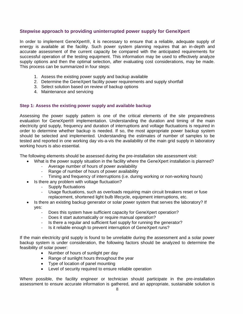
Stepwise approach to providing uninterrupted power supply for GeneXpert
In order to implement GeneXpert®, it is necessary to ensure that a reliable, adequate supply of energy is available at the facility. Such power system planning requires that an in-depth and accurate assessment of the current capacity be compared with the anticipated requirements for successful operation of the testing equipment. This information may be used to effectively analyze supply options and then the optimal selection, after evaluating cost considerations, may be made. This process can be summarized in four steps:
1. Assess the existing power supply and backup available
2. Determine the GeneXpert facility power requirements and supply shortfall 3. Select solution based on review of backup options
4. Maintenance and servicing
Step 1: Assess the existing power supply and available backup Assessing the power supply pattern is one of the critical elements of the site preparedness evaluation for GeneXpert® implementation. Understanding the duration and timing of the main electricity grid supply, frequency and duration of interruptions and voltage fluctuations is required in order to determine whether backup is needed. If so, the most appropriate power backup system should be selected and implemented. Understanding the estimates of number of samples to be tested and reported in one working day vis-a-vis the availability of the main grid supply in laboratory working hours is also essential. The following elements should be assessed during the pre-installation site assessment visit:
What is the power supply situation in the facility where the GeneXpert installation is planned? - Average number of hours of power availability - Range of number of hours of power availability - Timing and frequency of interruptions (i.e. during working or non-working hours)
Is there any problem with voltage fluctuation? - Supply fluctuations - Usage fluctuations, such as overloads requiring main circuit breakers reset or fuse
replacement, shortened light bulb lifecycle, equipment interruptions, etc.
Is there an existing backup generator or solar power system that serves the laboratory? If yes:
- Does this system have sufficient capacity for GeneXpert operation? - Does it start automatically or require manual operation? - Is there a regular and sufficient fuel supply for running the generator? - Is it reliable enough to prevent interruption of GeneXpert runs?
If the main electricity grid supply is found to be unreliable during the assessment and a solar power backup system is under consideration, the following factors should be analyzed to determine the feasibility of solar power:
Number of hours of sunlight per day
Range of sunlight hours throughout the year
Type of location of panel mounting
Level of security required to ensure reliable operation Where possible, the facility engineer or technician should participate in the pre-installation assessment to ensure accurate information is gathered, and an appropriate, sustainable solution is
9
recommended, in line with overall facility requirements. If possible, the power requirements for the laboratory, and specifically the GeneXpert instrument and associated requirements should be included as part of a comprehensive power strategy for the facility. Otherwise, a separate solution for the GeneXpert and associated laboratory should be developed. See Annex 3 for GeneXpert pre-installation checklist – power requirements.
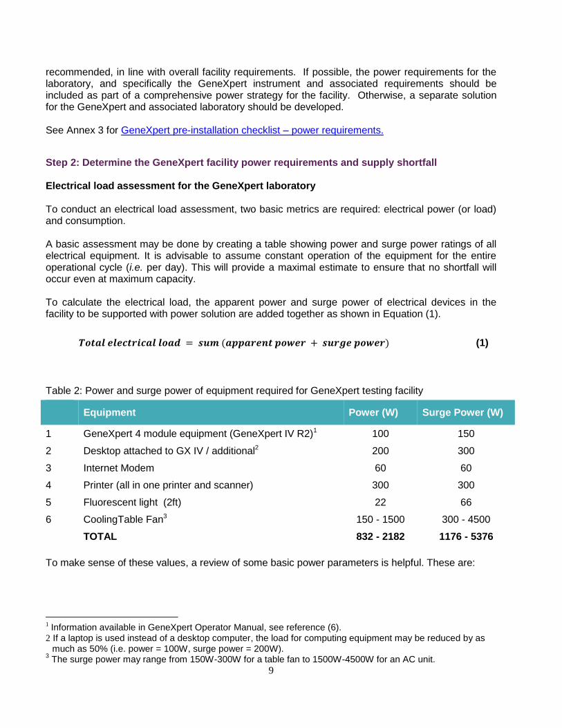
Step 2: Determine the GeneXpert facility power requirements and supply shortfall Electrical load assessment for the GeneXpert laboratory To conduct an electrical load assessment, two basic metrics are required: electrical power (or load) and consumption. A basic assessment may be done by creating a table showing power and surge power ratings of all electrical equipment. It is advisable to assume constant operation of the equipment for the entire operational cycle (i.e. per day). This will provide a maximal estimate to ensure that no shortfall will occur even at maximum capacity. To calculate the electrical load, the apparent power and surge power of electrical devices in the facility to be supported with power solution are added together as shown in Equation (1).
𝑻𝒐𝒕𝒂𝒍 𝒆𝒍𝒆𝒄𝒕𝒓𝒊𝒄𝒂𝒍 𝒍𝒐𝒂𝒅 = 𝒔𝒖𝒎 (𝒂𝒑𝒑𝒂𝒓𝒆𝒏𝒕 𝒑𝒐𝒘𝒆𝒓 + 𝒔𝒖𝒓𝒈𝒆 𝒑𝒐𝒘𝒆𝒓) (1)
Table 2: Power and surge power of equipment required for GeneXpert testing facility
Equipment Power (W) Surge Power (W)
1 GeneXpert 4 module equipment (GeneXpert IV R2)1 100 150
2 Desktop attached to GX IV / additional2 200 300
3 Internet Modem 60 60
4 Printer (all in one printer and scanner) 300 300
5 Fluorescent light (2ft) 22 66
6 CoolingTable Fan3 150 - 1500 300 - 4500
TOTAL 832 - 2182 1176 - 5376
To make sense of these values, a review of some basic power parameters is helpful. These are:
1 Information available in GeneXpert Operator Manual, see reference (6).
2 If a laptop is used instead of a desktop computer, the load for computing equipment may be reduced by as much as 50% (i.e. power = 100W, surge power = 200W).
3 The surge power may range from 150W-300W for a table fan to 1500W-4500W for an AC unit.
10
Real power (W): The real peak power, measured in watts (W), is the maximum sustained power that is drawn during the day. All devices that may be running simultaneously contribute to the real peak power. Surge power: Many devices containing motors require a larger power when starting than their normal rated value. A value for surge power should be available from the manufacturer. Apparent power (VA): The apparent power is calculated from the real power and the power factor and is used to calculate the true current drawn from the inverter. Power factor: Power factor for purely resistive loads, such as filament bulbs and heating elements, is one. Power factors for other devices, such as motors and florescent bulbs, is less than one. If you are not sure, this value can be estimated as 0.8 for electrical motors. However, for energy-efficient light bulbs it can range from 0.25 to 0.65, therefore it is preferable to follow the manufacturer’s recommended value and consult an electrical technician for guidance.
Step 3: Select solution based on review of backup options Solutions for providing continuous and stable supply include the following options:
UPS
batteries
hybrid solar inverter
solar panels
voltage regulator
In situations where the main grid supply is good (Scenario 1), a simple system consisting of UPS and batteries is enough to support the power outages and batteries can be adequately re-charged using the main grid electrical supply.
In situations where the main grid supply is less reliable (Scenarios 2-4), alternate sources of
electricity are needed and solar panels may be the most viable option in such circumstances. This is
true in most of Africa, as the continent enjoys the highest level of solar coverage as compared to
other geological locations. In some areas, where solar insolation is not adequate throughout the
year, a natural resource (gas, diesel, etc.) powered generator may be necessary. Use of a hybrid
solar inverter allows use of both the main grid supply and solar power, whichever is available, and
use of solar energy for charging the batteries can be prioritized. Any UPS solution requires voltage
regulation to ensure that the AC power is maintained within normal operating limits and the signal
quality is sufficient. This may be implemented using a separate voltage regulator or as an element of
the UPS.
The requirements for power backup for one to three Xpert MTB/RIF test runs to be completed in the event of a power outage are shown in Table 3.
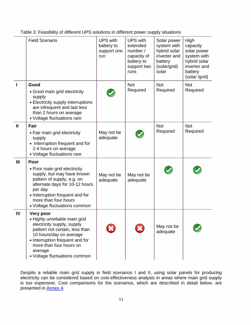
11
Table 3: Feasibility of different UPS solutions in different power supply situations
Field Scenario UPS with battery to support one run
UPS with extended number / capacity of battery to support two runs
Solar power system with hybrid solar inverter and battery (solar/grid) solar
High capacity solar power system with hybrid solar inverter and battery (solar /grid)
I Good
Good main grid electricity supply
Electricity supply interruptions are infrequent and last less than 2 hours on average
Voltage fluctuations rare
Not Required
Not Required
Not Required
II Fair
Fair main grid electricity supply
Interruption frequent and for 2-4 hours on average
Voltage fluctuations rare
May not be adequate
Not Required
Not Required
III Poor
Poor main grid electricity supply, but may have known pattern of supply, e.g. on alternate days for 10-12 hours per day
Interruption frequent and for more than four hours
Voltage fluctuations common
May not be adequate
May not be adequate
IV Very poor
Highly unreliable main grid electricity supply, supply pattern not certain, less than 10 hours/day on average
Interruption frequent and for more than four hours on average
Voltage fluctuations common
May not be adequate
Despite a reliable main grid supply in field scenarios I and II, using solar panels for producing electricity can be considered based on cost-effectiveness analysis in areas where main grid supply is too expensive. Cost comparisons for the scenarios, which are described in detail below, are presented in Annex 4.
12
Field scenario descriptions Field scenario I (Good):
Good main electrical grid supply
Electricity supply interruptions are infrequent and last less than 2 hours on average
Voltage fluctuations rare
In this scenario the aim of the power backup solution is to ensure that the test run which is ongoing at the time of the power outage can be completed without interruption. In field scenario I, where power outages rarely exceed a few minutes in duration, a small UPS/battery unit will be sufficient to ensure that the test cycle is not interrupted, but it is prudent to have a power backup unit with external battery packs where longer outages are frequent. The budget for the 'power solution unit' increases significantly if the unit also serves as a backup source of power for a longer period. The cost for such a unit depends on the equipment to be supported, duration of backup required and availability of routine power supply for batteries to be charged to provide backup in working hours. Here, as we can rely on main grid supply for batteries to get charged, there is no need to plan for alternate source of electricity such as solar panels. Solution: UPS with battery In such conditions where the main grid supply is good and voltage fluctuations are rare, UPS with the adequate capacity batteries can be effectively used to provide backup in infrequent and brief power outages. Such solutions were found to be satisfactory in 16 of an 18 site feasibility study in India. (see India case study). Advantages
- Maintenance-free UPS and absorbent glass mat (AGM) batteries - Compact, does not require much space, can be accommodated in a multilevel rack
Limitations
- Provide backup for limited period of time (one test run in this scenario)
- Rely on the main grid supply for batteries to get charged and provide backup, no alternate
source of electricity is used in this system
Maintenance requirements
- Cleaning of battery and UPS with cloth - weekly
- Tightening of the wiring connections - 6 monthly
13
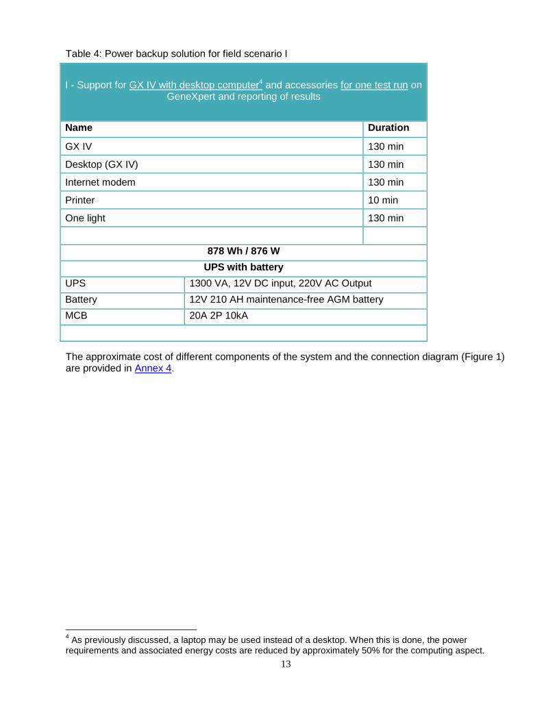
Table 4: Power backup solution for field scenario I
I - Support for GX IV with desktop computer4 and accessories for one test run on GeneXpert and reporting of results
Name Duration
GX IV 130 min
Desktop (GX IV) 130 min
Internet modem 130 min
Printer 10 min
One light 130 min
878 Wh / 876 W
UPS with battery
UPS 1300 VA, 12V DC input, 220V AC Output
Battery 12V 210 AH maintenance-free AGM battery
MCB 20A 2P 10kA
The approximate cost of different components of the system and the connection diagram (Figure 1) are provided in Annex 4.
4 As previously discussed, a laptop may be used instead of a desktop. When this is done, the power
requirements and associated energy costs are reduced by approximately 50% for the computing aspect.
14
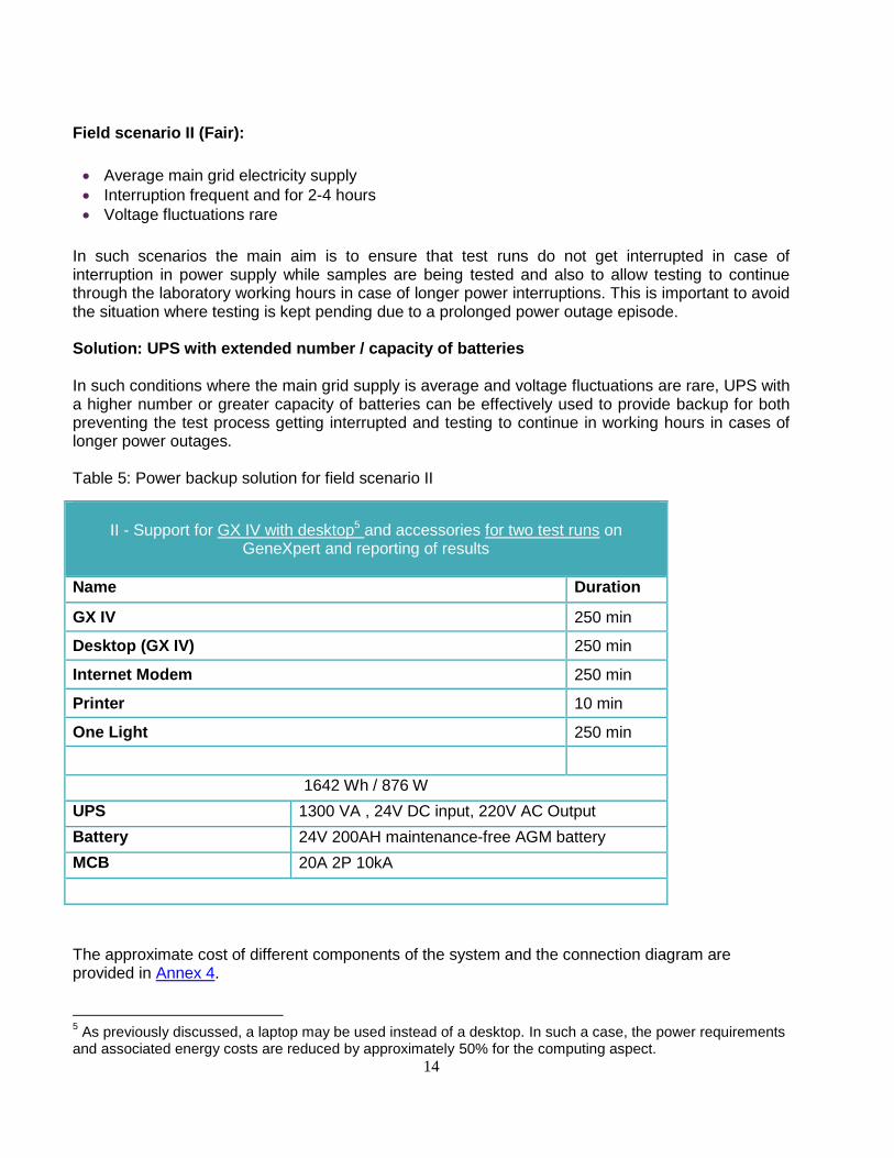
Field scenario II (Fair):
Average main grid electricity supply
Interruption frequent and for 2-4 hours
Voltage fluctuations rare
In such scenarios the main aim is to ensure that test runs do not get interrupted in case of interruption in power supply while samples are being tested and also to allow testing to continue through the laboratory working hours in case of longer power interruptions. This is important to avoid the situation where testing is kept pending due to a prolonged power outage episode. Solution: UPS with extended number / capacity of batteries In such conditions where the main grid supply is average and voltage fluctuations are rare, UPS with a higher number or greater capacity of batteries can be effectively used to provide backup for both preventing the test process getting interrupted and testing to continue in working hours in cases of longer power outages. Table 5: Power backup solution for field scenario II
The approximate cost of different components of the system and the connection diagram are provided in Annex 4.
5 As previously discussed, a laptop may be used instead of a desktop. In such a case, the power requirements
and associated energy costs are reduced by approximately 50% for the computing aspect.
II - Support for GX IV with desktop5 and accessories for two test runs on
GeneXpert and reporting of results
Name Duration
GX IV 250 min
Desktop (GX IV) 250 min
Internet Modem 250 min
Printer 10 min
One Light 250 min
1642 Wh / 876 W
UPS 1300 VA , 24V DC input, 220V AC Output
Battery 24V 200AH maintenance-free AGM battery
MCB 20A 2P 10kA
15
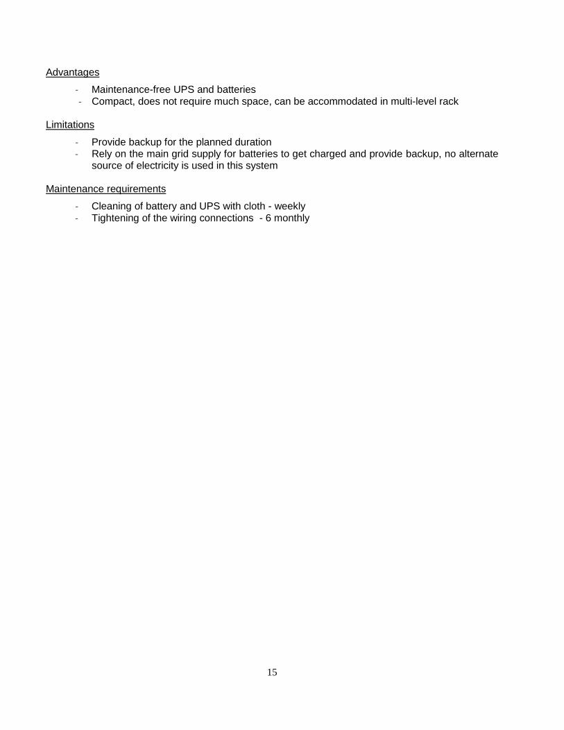
Advantages
- Maintenance-free UPS and batteries - Compact, does not require much space, can be accommodated in multi-level rack
Limitations
- Provide backup for the planned duration - Rely on the main grid supply for batteries to get charged and provide backup, no alternate
source of electricity is used in this system Maintenance requirements
- Cleaning of battery and UPS with cloth - weekly - Tightening of the wiring connections - 6 monthly
16
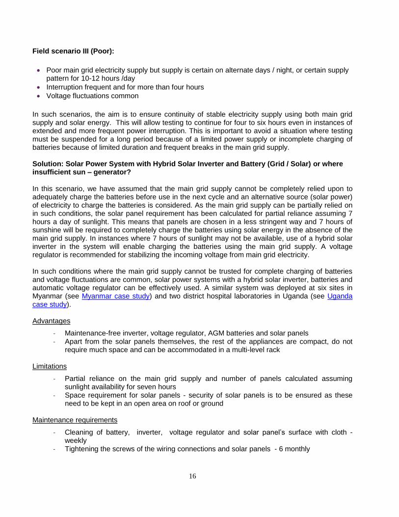
Field scenario III (Poor):
Poor main grid electricity supply but supply is certain on alternate days / night, or certain supply pattern for 10-12 hours /day
Interruption frequent and for more than four hours
Voltage fluctuations common
In such scenarios, the aim is to ensure continuity of stable electricity supply using both main grid supply and solar energy. This will allow testing to continue for four to six hours even in instances of extended and more frequent power interruption. This is important to avoid a situation where testing must be suspended for a long period because of a limited power supply or incomplete charging of batteries because of limited duration and frequent breaks in the main grid supply. Solution: Solar Power System with Hybrid Solar Inverter and Battery (Grid / Solar) or where insufficient sun – generator? In this scenario, we have assumed that the main grid supply cannot be completely relied upon to adequately charge the batteries before use in the next cycle and an alternative source (solar power) of electricity to charge the batteries is considered. As the main grid supply can be partially relied on in such conditions, the solar panel requirement has been calculated for partial reliance assuming 7 hours a day of sunlight. This means that panels are chosen in a less stringent way and 7 hours of sunshine will be required to completely charge the batteries using solar energy in the absence of the main grid supply. In instances where 7 hours of sunlight may not be available, use of a hybrid solar inverter in the system will enable charging the batteries using the main grid supply. A voltage regulator is recommended for stabilizing the incoming voltage from main grid electricity. In such conditions where the main grid supply cannot be trusted for complete charging of batteries and voltage fluctuations are common, solar power systems with a hybrid solar inverter, batteries and automatic voltage regulator can be effectively used. A similar system was deployed at six sites in Myanmar (see Myanmar case study) and two district hospital laboratories in Uganda (see Uganda case study). Advantages
- Maintenance-free inverter, voltage regulator, AGM batteries and solar panels - Apart from the solar panels themselves, the rest of the appliances are compact, do not
require much space and can be accommodated in a multi-level rack Limitations
- Partial reliance on the main grid supply and number of panels calculated assuming sunlight availability for seven hours
- Space requirement for solar panels - security of solar panels is to be ensured as these need to be kept in an open area on roof or ground
Maintenance requirements
- Cleaning of battery, inverter, voltage regulator and solar panel’s surface with cloth - weekly
- Tightening the screws of the wiring connections and solar panels - 6 monthly
17
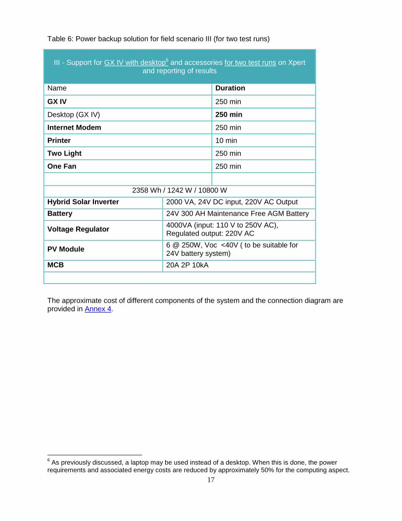
Table 6: Power backup solution for field scenario III (for two test runs)
The approximate cost of different components of the system and the connection diagram are provided in Annex 4.
6 As previously discussed, a laptop may be used instead of a desktop. When this is done, the power
requirements and associated energy costs are reduced by approximately 50% for the computing aspect.
III - Support for GX IV with desktop6 and accessories for two test runs on Xpert
and reporting of results
Name Duration
GX IV 250 min
Desktop (GX IV) 250 min
Internet Modem 250 min
Printer 10 min
Two Light 250 min
One Fan 250 min
2358 Wh / 1242 W / 10800 W
Hybrid Solar Inverter 2000 VA, 24V DC input, 220V AC Output
Battery 24V 300 AH Maintenance Free AGM Battery
Voltage Regulator 4000VA (input: 110 V to 250V AC), Regulated output: 220V AC
PV Module 6 @ 250W, Voc <40V ( to be suitable for 24V battery system)
MCB 20A 2P 10kA
18
Field scenario IV (Very poor):
Highly unreliable main grid electricity supply, supply pattern not certain, less than 10 hours/day
Interruption frequent and for more than four hours
Voltage fluctuations common
In this scenario, we cannot trust the main grid supply and need to have an alternate system to ensure continued operation of the equipment. The aim is to ensure continuity of a stable electricity supply using solar energy and also to have the option of using the main grid supply when available. This will allow testing to continue for four to six hours in instances of grossly unreliable power supply. It is important to avoid situations where testing has to be kept suspended for days and samples are wasted or need to be re-collected. Solution: High capacity solar power systems with hybrid solar inverter and battery (solar / grid) In this situation, the main grid electricity supply is not certain and cannot be relied upon for completely charging the batteries. Thus, solar power is instituted to charge the batteries. To ensure sufficient capacity, the solar panel system should be designed on the assumption that there is no input from the main grid. As previously stated, voltage regulation should be instituted either as a separate component or as an element of the UPS. Under conditions where the main grid supply is highly unreliable, high capacity solar power systems with hybrid inverter and batteries and voltage regulator can be effectively used to provide backup to prevent the test process from getting interrupted and testing to continue even with extended power outages. Advantages
- Maintenance free inverter, voltage regulator, AGM batteries and solar panels - Apart from solar panels, the rest of the appliances are compact, do not require much
space and can be accommodated in a multilevel rack Limitations
- Number of panels are calculated assuming sunlight availability for four hours a day - Space requirement for solar panels - security of solar panels is to be ensured as these
need to be kept in an open area on roof or ground Maintenance requirements
- Cleaning of battery, inverter, voltage regulator and solar panel’s surface with cloth - weekly
- Tightening the screws of the wiring connections and solar panels - 6 monthly
19
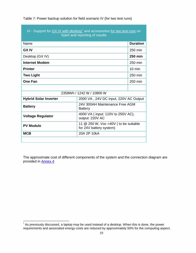
Table 7: Power backup solution for field scenario IV (for two test runs)
The approximate cost of different components of the system and the connection diagram are provided in Annex 4
7 As previously discussed, a laptop may be used instead of a desktop. When this is done, the power
requirements and associated energy costs are reduced by approximately 50% for the computing aspect.
IV - Support for GX IV with desktop7 and accessories for two test runs on
Xpert and reporting of results
Name Duration
GX IV 250 min
Desktop (GX IV) 250 min
Internet Modem 250 min
Printer 10 min
Two Light 250 min
One Fan 250 min
2358Wh / 1242 W / 10800 W
Hybrid Solar Inverter 2000 VA , 24V DC input, 220V AC Output
Battery 24V 300AH Maintenance Free AGM Battery
Voltage Regulator 4000 VA ( input: 110V to 250V AC), output: 220V AC
PV Module 11 @ 250 W, Voc <40V ( to be suitable for 24V battery system)
MCB 20A 2P 10kA
20
Step 4: Maintenance and servicing
It is critical to perform routine maintenance of UPS equipment in order to ensure its effective functioning and to prolong its lifespan.
The maintenance and servicing requirements for each proposed solution are described above. All maintenance and servicing activities should be scheduled in advance and documented.
Simple maintenance tasks (such as weekly cleaning) may be conducted by laboratory staff or facility support staff, while more technical tasks may be done by facility engineers or authorized service providers.
21
References
1. World Health Organization. Policy statement: automated real-time nucleic acid amplification
technology for rapid and simultaneous detection of tuberculosis and rifampicin resistance:
Xpert MTB/RIF. Policy statement. Geneva, Switz World Heal …. 2011;
2. World Health Organization. Automated real-time nucleic acid amplification technology for
rapid and simultaneous detection of tuberculosis and rifampicin resistance: Xpert MTB/RIF
assay for the diagnosis of pulmonary and extrapulmonary TB in adults and children. POLICY
UPDATE. 2013;
3. World Health Organization. Prerequisites to country implementation of Xpert MTB/RIF and
key action points at country level. Geneva, Switzerland.
http://whqlibdoc.who.int/hq/2011/WHO_HTM_TB_2011.12_eng.pdf
4. Creswell J, Codlin AJ, Andre E, Micek MA, Bedru A, Carter EJ, et al. Results from early
programmatic implementation of Xpert MTB/RIF testing in nine countries. BMC Infect Dis.
2014;14:2.
5. The Economist. Energy in the Developing World. Power to the People. Technology
Quarterly. Q4, 2010. http://www.economist.com/node/16909923
6. Cepheid. GeneXpert DX System. Operator Manual. Software version 4. June 2012.
22
Case studies
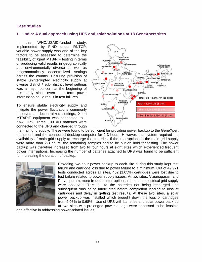
1. India: A dual approach using UPS and solar solutions at 18 GeneXpert sites
In this WHO/USAID-funded study, implemented by FIND under RNTCP, variable power supply was one of the key factors to be assessed to determine the feasibility of Xpert MTB/RIF testing in terms of producing valid results in geographically and environmentally diverse as well as programmatically decentralized settings across the country. Ensuring provision of stable uninterrupted electricity supply at diverse district / sub- district level settings was a major concern at the beginning of this study since even short-term power interruption could result in test failures. To ensure stable electricity supply and mitigate the power fluctuations commonly observed at decentralized settings, Xpert MTB/RIF equipment was connected to 1 KVA UPS. Three 100 AH batteries were connected to the UPS and charged through the main grid supply. These were found to be sufficient for providing power backup to the GeneXpert equipment and the connected desktop computer for 2-3 hours. However, this system required the availability of main grid supply to recharge the batteries. If the interruptions in the main grid supply were more than 2-3 hours, the remaining samples had to be put on hold for testing. The power backup was therefore increased from two to four hours at eight sites which experienced frequent power interruptions. Increasing the number of batteries attached to UPS was found to be sufficient for increasing the duration of backup.
Providing two-hour power backup to each site during this study kept test failure and cartridge loss due to power failure to a minimum. Out of 42,971 tests conducted across all sites, 452 (1.05%) cartridges were lost due to test failure related to power supply issues. At two sites, Vizianagaram and Parvatipuram, more frequent interruptions in the main electrical grid supply were observed. This led to the batteries not being recharged and subsequent runs being interrupted before completion leading to loss of cartridges and delay in getting test results. At these two sites, a solar power backup was installed which brought down the loss of cartridges from 2.05% to 0.68%. Use of UPS with batteries and solar power back up at two sites with prolonged power outage were assessed to be feasible
and effective in addressing power-related issues.
23
Table 8: Effectiveness of a solar power backup system in preventing loss of cartridges at two sites with grossly insufficient main grid supply
Site Before solar power back up After solar power back up
Duration (month)
Total tests
Cartridge loss
Rate of loss (%)
Duration (month)
Total tests
Cartridge loss
Rate of loss (%)
Vizianagaram 6.4 4052 100 2.47 6.2 3805 26 0.68
Parvatipuram 6.2 2329 31 1.33 6.3 2413 16 0.66
Total 6381 131 2.05 6218 42 0.68
Solar panels at GeneXpert study site at Parvatipuram (Acknowledgement: Feasibility study team)
24
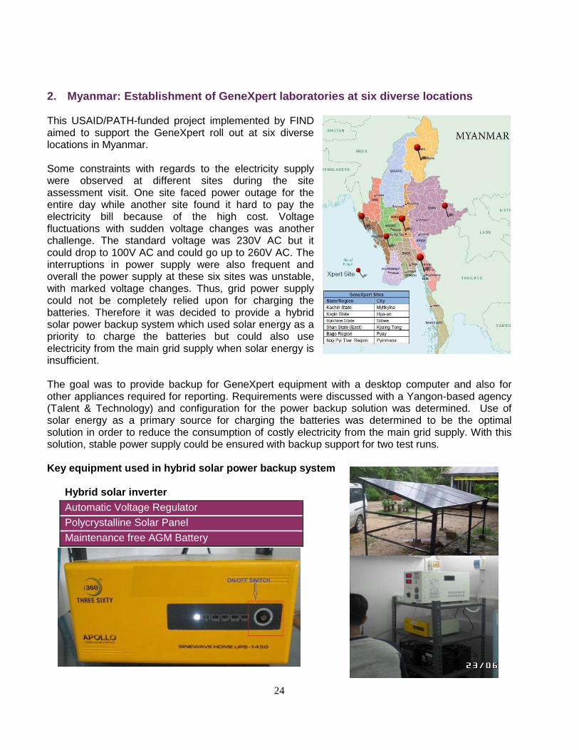
2. Myanmar: Establishment of GeneXpert laboratories at six diverse locations This USAID/PATH-funded project implemented by FIND aimed to support the GeneXpert roll out at six diverse locations in Myanmar. Some constraints with regards to the electricity supply were observed at different sites during the site assessment visit. One site faced power outage for the entire day while another site found it hard to pay the electricity bill because of the high cost. Voltage fluctuations with sudden voltage changes was another challenge. The standard voltage was 230V AC but it could drop to 100V AC and could go up to 260V AC. The interruptions in power supply were also frequent and overall the power supply at these six sites was unstable, with marked voltage changes. Thus, grid power supply could not be completely relied upon for charging the batteries. Therefore it was decided to provide a hybrid solar power backup system which used solar energy as a priority to charge the batteries but could also use electricity from the main grid supply when solar energy is insufficient. The goal was to provide backup for GeneXpert equipment with a desktop computer and also for other appliances required for reporting. Requirements were discussed with a Yangon-based agency (Talent & Technology) and configuration for the power backup solution was determined. Use of solar energy as a primary source for charging the batteries was determined to be the optimal solution in order to reduce the consumption of costly electricity from the main grid supply. With this solution, stable power supply could be ensured with backup support for two test runs. Key equipment used in hybrid solar power backup system
Hybrid solar inverter
Automatic Voltage Regulator
Polycrystalline Solar Panel
Maintenance free AGM Battery
25
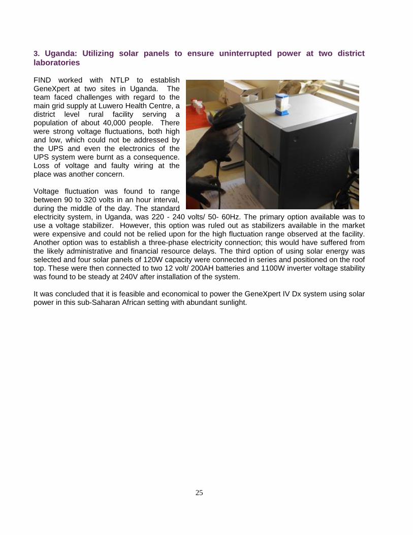
3. Uganda: Utilizing solar panels to ensure uninterrupted power at two district laboratories
FIND worked with NTLP to establish GeneXpert at two sites in Uganda. The team faced challenges with regard to the main grid supply at Luwero Health Centre, a district level rural facility serving a population of about 40,000 people. There were strong voltage fluctuations, both high and low, which could not be addressed by the UPS and even the electronics of the UPS system were burnt as a consequence. Loss of voltage and faulty wiring at the place was another concern. Voltage fluctuation was found to range between 90 to 320 volts in an hour interval, during the middle of the day. The standard electricity system, in Uganda, was 220 - 240 volts/ 50- 60Hz. The primary option available was to use a voltage stabilizer. However, this option was ruled out as stabilizers available in the market were expensive and could not be relied upon for the high fluctuation range observed at the facility. Another option was to establish a three-phase electricity connection; this would have suffered from the likely administrative and financial resource delays. The third option of using solar energy was selected and four solar panels of 120W capacity were connected in series and positioned on the roof top. These were then connected to two 12 volt/ 200AH batteries and 1100W inverter voltage stability was found to be steady at 240V after installation of the system. It was concluded that it is feasible and economical to power the GeneXpert IV Dx system using solar power in this sub-Saharan African setting with abundant sunlight.
26
Conclusions and recommendations Uninterrupted power supply (UPS) is an essential requirement for successful operation of the GeneXpert instrument in peripheral settings. In order for the equipment to function properly and execute accurate runs it is necessary for its power source to be stable and reliable over the operational cycle. In many locations where the instrument is located, the local power supply does not meet this criterion. In these situations, described as scenarios II, III and IV in this report, there are various solutions that can be implemented to ensure that adequate backup power is available.
Whenever possible, it is suggested that these solutions leverage the tremendous geological advantage enjoyed by much of Africa in terms of abundance of sunlight. Sunlight or solar-based solutions offer the lowest cost (over the long term) due primarily to zero fuel cost and low maintenance requirements. Regardless of the UPS solution, it is imperative that the power supply meets the normal operating levels that the equipment requires. This can be ensured by instituting voltage regulation, either as a separate device or as a component of the UPS.
As this document describes, the backup power supply may be batteries, solar energy or in some cases a gas or diesel generator. The choice of which option to use should be based on a thorough evaluation of the site needs and the availability of energy options. Following the steps outlined in this document will lead to the selection of an effective solution that should ensure the GeneXpert can be operated safely and efficiently and the communities served can benefit from rapid diagnosis and timely treatment initiation.
27
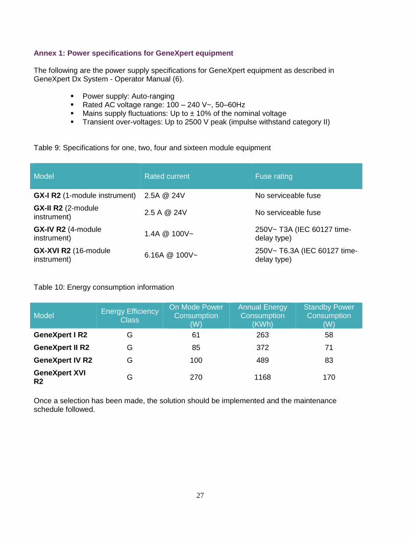
Annex 1: Power specifications for GeneXpert equipment
The following are the power supply specifications for GeneXpert equipment as described in GeneXpert Dx System - Operator Manual (6).
Power supply: Auto-ranging Rated AC voltage range: 100 – 240 V~, 50–60Hz Mains supply fluctuations: Up to ± 10% of the nominal voltage Transient over-voltages: Up to 2500 V peak (impulse withstand category II)
Table 9: Specifications for one, two, four and sixteen module equipment
Model
Rated current Fuse rating
GX-I R2 (1-module instrument) 2.5A @ 24V No serviceable fuse
GX-II R2 (2-module instrument)
2.5 A @ 24V No serviceable fuse
GX-IV R2 (4-module instrument)
1.4A @ 100V~ 250V~ T3A (IEC 60127 time-delay type)
GX-XVI R2 (16-module instrument)
6.16A @ 100V~ 250V~ T6.3A (IEC 60127 time-delay type)
Table 10: Energy consumption information
Model Energy Efficiency
Class
On Mode Power Consumption
(W)
Annual Energy Consumption
(KWh)
Standby Power Consumption
(W)
GeneXpert I R2 G 61 263 58
GeneXpert II R2 G 85 372 71
GeneXpert IV R2 G 100 489 83
GeneXpert XVI R2
G 270 1168 170
Once a selection has been made, the solution should be implemented and the maintenance schedule followed.
28
Annex 2: Backup system considerations
Batteries When considering which battery to use it is important to determine the battery size (or battery bank) necessary. If used in conjunction with a solar supply, the battery bank need only supply the difference between the demand and solar generation. This parameter is directly correlated to the capacity of the battery. Battery size required depends on the power consumption of equipment, and the time period for which the batteries are expected to provide backup. The power consumption is measured in watts (W). To calculate the energy or power required over a period of time, multiply the average power consumption with the hours of use. For example, a 13 W light fitting, planned to be used for 2 hours, will take 13 x 2 = 26 watt-hours (WH) from the battery. This is to be calculated for all equipment you wish to use and added up to find the total requirement. Battery capacity is measured in amp hours (e.g. 17 AH). We need to convert this to watt hours by multiplying the AH figure by the battery voltage (e.g. 12 V). For a 17 AH, 12 V battery, the watt hour calculation is 17 x 12 = 204 WH. This means the battery could supply 204 W for 1 hour or 102 W for 2 hours (i. e. the more energy you take, the faster the battery discharges). Types of batteries: Lead-acid battery The capacity of a lead-acid battery depends on the rate at which it is discharged. The faster the current is drawn from it, the less capacity it will have. Manufactures normally provide a 20 amp-hour rate but since the batteries will probably be discharged over a time period that is greater than 20 hours (especially if you have entered 1 or more days autonomy), this value may result in excess battery capacity. The term days of autonomy means the number of days a battery can provide electricity to the equipment connected to the system without a recharge. In designs illustrated in this document, we assume depth of discharge (DOD) as 50% and UPS / inverter efficiency as 70% for calculating the battery capacity. We have not considered any buffer in battery power calculation as DOD is taken as 50% instead of routinely applied 70% which allow us selecting higher battery capacity with some margin / buffer. It is advisable to obtain the detailed battery specification from the manufacturers. Absorbent glass mat (AGM) battery AGM is a type of valve regulated lead acid (VRLA) battery which offers many conveniences that are not available in other types of batteries. They are a type of dry cell battery. Advantages:
1. No spills - AGM battery is considered spill-proof because the electrolyte or battery acid is contained within glass mats that keep the hazardous material trapped in it
29
even if the outer layer of the battery breaks. This is highly beneficial to the environment as battery acid leaks are one of the leading contributors to the contamination of the water table. Also, the fact that the battery cannot spill lowers the risk related to its handling and shipping.
2. Low maintenance - An AGM battery uses recombinant technology, which means that the oxygen and hydrogen recombine inside the battery. It utilizes a gas phase transfer of oxygen to the negative plates in order to recombine them back into water during the proper process of charging. This prevents any water loss from electrolysis, and eliminates the need for refilling the water in the battery during its lifespan.
3. Low self-discharge - AGM batteries have a maximum 3% per month discharge rate, which is very low due to low internal resistance. It means that it can be stored for longer periods of time without having to charge them.
Disadvantages:
Higher cost - AGM batteries may cost up to twice as much as other types of batteries.
Power Regulators: UPS/Inverter The UPS/ hybrid inverter size is chosen based on the amount of current that will be drawn from the inverter under peak power and surge conditions. For the solutions illustrated here, we assumed a power factor of 0.80 for calculating the electric load and selected a 50% higher UPS surge power capacity. Types of UPS (per IEC Standard 62040-3): Passive standby - A typical offline backup power supply will continuously provide power with some filtering (typically the same as on a surge protection power strip) from the utility. When utility power fails, the device will start its internal inverter, and then mechanically transfer from utility power to inverter output. Advantages:
- Low cost: can be widely implemented in an organization - Small size: unobtrusive - Simple design: little or no training required to understand full functionality
Disadvantages:
- No power conditioning - Slow transfer time - Simple battery charger may shorten battery life and increase recharge time - Limited additional functionality may not meet enterprise needs - Short backup time
Line-interactive UPS - It conditions and regulates the AC power from the utility, generally using only one main power converter. During normal operation, the line-interactive UPS takes utility power and passes it through a transformer with various tap selections on the output. When utility power is high, the line-interactive UPS selects a tap to lower (buck) the output voltage. Similarly, when the utility voltage is low, the UPS selects a tap to increase (boost) the output voltage. In developing countries or other infrastructure-challenged areas where the AC line voltage is unstable, fluctuates wildly, or is highly distorted, a line-interactive UPS may go to battery once or twice a day or even more frequently. This is because the line-interactive design has a somewhat limited ability to keep large voltage swings and heavy distortion from reaching the load unless it disconnects from the AC supply
30
and transfers to battery power, although the line-interactive UPS will provide an output voltage within the IEC.
Advantages:
- Low cost - Sine wave output - Wider input range - Buck & boost regulation - Efficient - Surge protection - EMI/RFI/noise suppression - Lower electricity consumption - Higher reliability - Less heat load on the facility
Disadvantages:
- Minimal load protection - Spike and surge protection components degrade over time - The line-interactive UPS may not be the appropriate choice for installations where AC
power is unstable or highly distorted, because battery power will be used too often to keep the UPS output within specifications and also where power factor correction is required and load equipment does not perform this function.
Double Conversion (On-line) UPS - As its name implies, a double-conversion on-line UPS converts power twice. First, AC input, with all of its voltage spikes, distortion, and other anomalies, is converted into DC. Second, DC is converted back into AC that is tightly regulated by the UPS. This AC output can even have a different frequency from the AC input — something not possible with a line-interactive UPS. All of the power provided to the load equipment goes through this double-conversion process when AC input is present.
Advantages:
- Zero transfer time - Excellent surge and noise suppression - Constant voltage output. - 100% power conditioning - Input power factor correction - Operates less often from battery when the input voltage is highly distorted or wildly
fluctuating - Power factor correction provided, regardless of load type - More compact and lightweight, especially at higher power levels
Disadvantages:
- Higher heat output - More expensive - Lower efficiency - No neutral conditioning - Low MTBF - Consumes more electricity compared to line interactive.
Above 5000 VA, line-interactive UPS should not be used due to its larger size and greater cost. Below 750 VA, double-conversion should not be used. Instead, line-interactive UPS is more practical for smaller loads. In consideration of the most likely implementations of GeneXpert, we have recommended line-interactive UPS/hybrid inverter with minimum
31
transfer switching time of 10 ms (half of sine wave) for the solutions described in this document. Inverters There are two types of inverters: sine wave and square wave. Sine wave is preferable as that is the signal form from the main grid supply. Sine wave inverters provide longer power backup and are usually less noisy in comparison to square wave inverters. Hybrid solar inverter Hybrid solar inverters convert solar DC energy to AC. They are designed to operate over wide ranges, as the level of solar insolation varies throughout the day and over the course of a year. Voltage regulator Voltage regulators accept various types of input energy and deliver a fixed desired output. Typically, this means converting a DC supply to an AC sinusoidal output that is comparable to the grid supply. However, it may also be for the purpose of further processing an AC signal to achieve a purer signal. As most equipment is designed with the assumption of grid level energy supply, this is a critical component of any alternative or backup energy system.
Photovoltaic (PV) modules / solar panels Photovoltaic panels are used to produce electricity using renewable solar energy. The energy performance of a photovoltaic system is influenced by a number of factors.These may include resource and design elements such as the amount of solar radiation hitting the solar collectors, the collector type, power capacity, area, efficiency, nominal operating cell temperature and temperature coefficient, as well as the solar tracking mode (i.e. fixed, one-axis, azimuth or two-axis tracker), the slope and the azimuth (physical orientation) of the collector. Other factors include the use of an inverter to transform the DC output to AC for systems that include AC loads or a grid-connection, and the PV array control method (i.e. maximum power point tracker or clamped) for off-grid systems. The energy performance of an off-grid system will also be influenced by the battery days of autonomy, voltage, efficiency, maximum depth of discharge, temperature and capacity, as well as the charge controller efficiency. There will be a slight variation in performance from panel to panel and the performance of an array of panels will be dictated by the worst panel. Taking into consideration the performance of the solar panel, DC cable losses and accumulation of dirt and dust on the panels, we have assumed an efficiency of 85% for the solar panels in the solution illustrated. It is recommended to obtain the solar panel efficiency data from the manufacturers’ specification sheet. The power generation rating of a solar panel is also given in watts (e.g. STP 010, 10W). To calculate the energy a solar panel can supply to the battery, multiply watts with the period of sun light exposure in hours. The product obtained thus needs to be adjusted for efficiency factor and needs to be further multiplied by 0.85 (for 85% efficiency). This allows accounting for natural system losses. For a solar panel of 10 W capacity and with 4 hours of sunlight, the amount of energy this panel can supply to the battery will be 34 WH (10 x 4 x 0.85). We need to know how much energy batteries can store to select a solar panel that can replenish the ‘stock’ of energy in the batteries in line with usage.
Generators
32
The selection of a suitable generator is similar to the selection of a UPS. First, the capacity necessary is determined and then the generator is selected based upon its ability to meet those power requirements over the estimated operational interval. Cable sizing Selecting a suitable cable mainly depends on the length and material of the cable selected. Location of the equipment should be nearer to the source to have lower voltage drop and power losses. The power loss is due to the resistance of the wires. As current travels along the cable, power is lost as heat into the environment (Equation (2) below).
𝒑𝒐𝒘𝒆𝒓 𝒍𝒐𝒔𝒔 = 𝒄𝒖𝒓𝒓𝒆𝒏𝒕 ∙ (𝒓𝒆𝒔𝒊𝒔𝒕𝒂𝒏𝒄𝒆)𝟐 (2) According to regulations, the total voltage drop to the end of the wiring system should not exceed 4%. The electrical designer shall recommend the size of cable to be used based on the specific situation. Cable laying should be done in accordance with the carefully and systematically planned design. The proper sizing of an electrical (load bearing) cable is important to ensure that the cable can:
Operate continuously under full load without being damaged Withstand the worst short circuit currents flowing through the cable Provide the load with a suitable voltage (and avoid excessive voltage drops) Ensure operation of protective devices during an earth fault (optional)
All cable sizing methods involve a basic six step process:
1. Gather data about the cable, its installation conditions and the load that it will carry 2. Determine the minimum cable size based on continuous current-carrying capacity 3. Determine the minimum cable size based on voltage drop considerations 4. Determine the minimum cable size based on short circuit temperature rise 5. Determine the minimum cable size based on earth fault loop impedance 6. Select the cable based on the largest sizes calculated in steps 2, 3, 4 and 5
The size of cable assumed for solutions illustrated in this document is based on standard application. That is, the electrical equipment used will be within approximately 6m. Larger cables can be used if the distance of the cable route is longer.
33
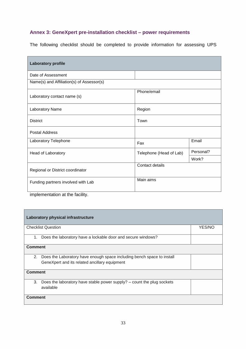
Annex 3: GeneXpert pre-installation checklist – power requirements
The following checklist should be completed to provide information for assessing UPS
implementation at the facility.
Laboratory profile
Date of Assessment
Name(s) and Affiliation(s) of Assessor(s)
Laboratory contact name (s) Phone/email
Laboratory Name Region
District Town
Postal Address
Laboratory Telephone
Fax Email
Head of Laboratory
Telephone (Head of Lab)
Personal?
Work?
Regional or District coordinator Contact details
Funding partners involved with Lab
Main aims
Laboratory physical infrastructure
Checklist Question YES/NO
1. Does the laboratory have a lockable door and secure windows?
Comment
2. Does the Laboratory have enough space including bench space to install
GeneXpert and its related ancillary equipment
Comment
3. Does the laboratory have stable power supply? – count the plug sockets
available
Comment
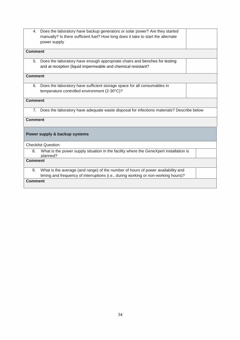
34
Power supply & backup systems
Checklist Question
8. What is the power supply situation in the facility where the GeneXpert installation is planned?
Comment
9. What is the average (and range) of the number of hours of power availability and
timing and frequency of interruptions (i.e., during working or non-working hours)?
Comment
4. Does the laboratory have backup generators or solar power? Are they started
manually? Is there sufficient fuel? How long does it take to start the alternate
power supply
Comment
5. Does the laboratory have enough appropriate chairs and benches for testing
and at reception (liquid impermeable and chemical resistant?
Comment
6. Does the laboratory have sufficient storage space for all consumables in
temperature controlled environment (2-30°C)?
Comment
7. Does the laboratory have adequate waste disposal for infections materials? Describe below
Comment
35
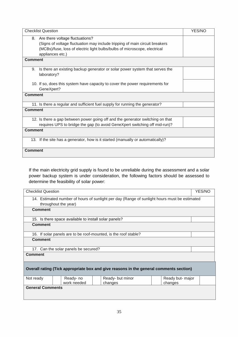
If the main electricity grid supply is found to be unreliable during the assessment and a solar
power backup system is under consideration, the following factors should be assessed to
determine the feasibility of solar power:
Overall rating (Tick appropriate box and give reasons in the general comments section)
Not ready Ready- no work needed
Ready- but minor changes
Ready but- major changes
General Comments
Checklist Question YES/NO
8. Are there voltage fluctuations?
(Signs of voltage fluctuation may include tripping of main circuit breakers
(MCBs)/fuse, loss of electric light bulbs/bulbs of microscope, electrical
appliances etc.)
Comment
9. Is there an existing backup generator or solar power system that serves the
laboratory?
10. If so, does this system have capacity to cover the power requirements for
GeneXpert?
Comment
11. Is there a regular and sufficient fuel supply for running the generator?
Comment
12. Is there a gap between power going off and the generator switching on that
requires UPS to bridge the gap (to avoid GeneXpert switching off mid-run)?
Comment
13. If the site has a generator, how is it started (manually or automatically)?
Comment
Checklist Question YES/NO
14. Estimated number of hours of sunlight per day (Range of sunlight hours must be estimated
throughout the year)
Comment
15. Is there space available to install solar panels?
Comment
16. If solar panels are to be roof-mounted, is the roof stable?
Comment
17. Can the solar panels be secured?
Comment
36
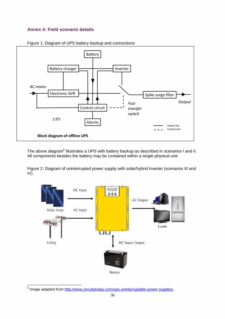
Annex 4: Field scenario details
Figure 1: Diagram of UPS battery backup and connections
The above diagram8 illustrates a UPS with battery backup as described in scenarios I and II. All components besides the battery may be contained within a single physical unit.
Figure 2: Diagram of uninterrupted power supply with solar/hybrid inverter (scenarios III and IV)
8 Image adapted from http://www.circuitstoday.com/ups-uninterruptable-power-supplies.
Battery
Battery charger
Electronic AVR
Inverter
Spike surge filter
Control circuit
Alarms
AC mains
Fast transfer switch
Output
Power lineControl line
Block diagram of offline UPS
UPS
37
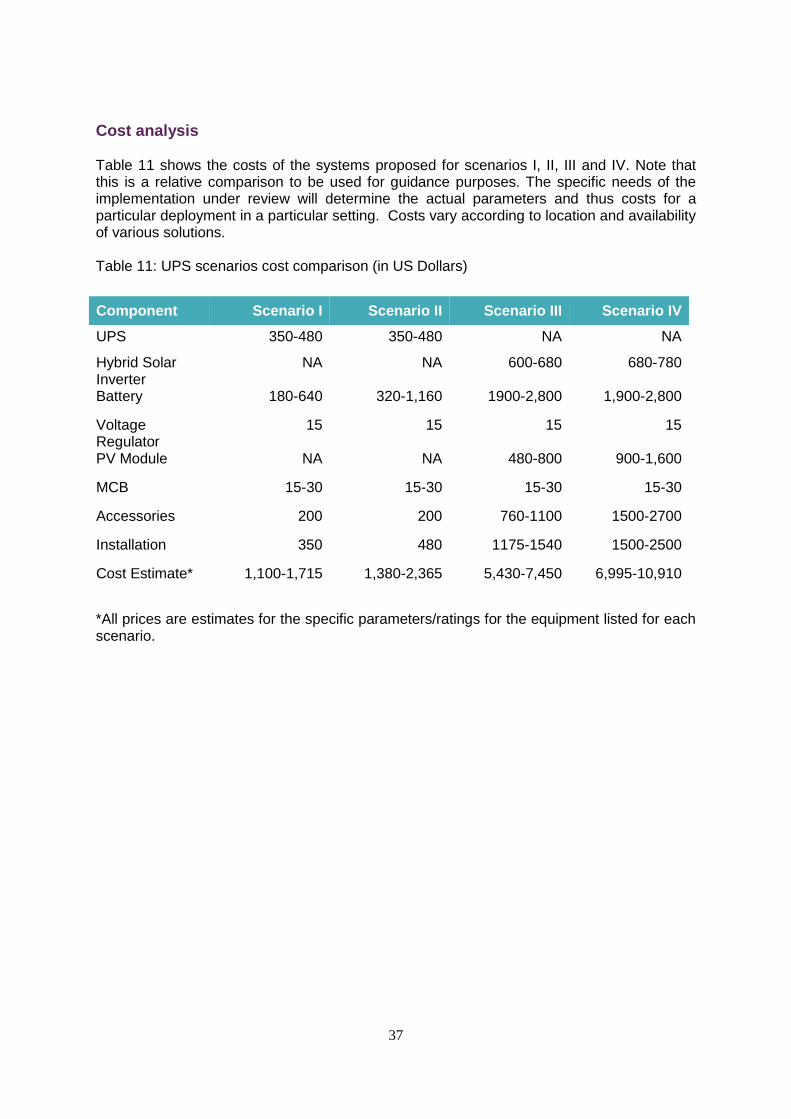
Cost analysis
Table 11 shows the costs of the systems proposed for scenarios I, II, III and IV. Note that this is a relative comparison to be used for guidance purposes. The specific needs of the implementation under review will determine the actual parameters and thus costs for a particular deployment in a particular setting. Costs vary according to location and availability of various solutions. Table 11: UPS scenarios cost comparison (in US Dollars)
Component Scenario I Scenario II Scenario III Scenario IV
UPS 350-480 350-480 NA NA
Hybrid Solar Inverter
NA NA 600-680 680-780
Battery 180-640 320-1,160 1900-2,800 1,900-2,800
Voltage Regulator
15 15 15 15
PV Module NA NA 480-800 900-1,600
MCB 15-30 15-30 15-30 15-30
Accessories 200 200 760-1100 1500-2700
Installation 350 480 1175-1540 1500-2500
Cost Estimate* 1,100-1,715 1,380-2,365 5,430-7,450 6,995-10,910
*All prices are estimates for the specific parameters/ratings for the equipment listed for each scenario.


