Protronic 100/500/550 Controllers for process …...Protronic 100/500/550 Digitric 500 Controllers...
44
Protronic 100/500/550 Digitric 500 Controllers for process engineering Controllers for industry PROFIBUS-DP interface and module Manual 42/62-50050 EN Rev. 02
Transcript of Protronic 100/500/550 Controllers for process …...Protronic 100/500/550 Digitric 500 Controllers...
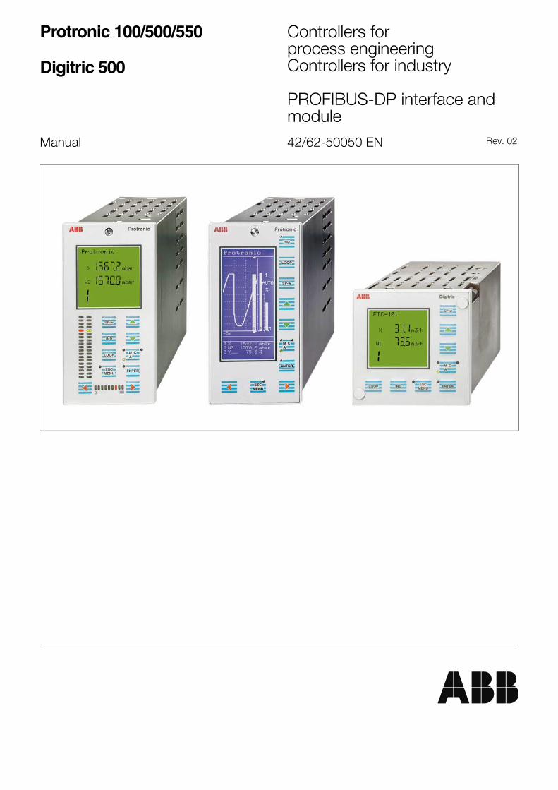
Protronic 100/500/550
Digitric 500
Controllers forprocess engineeringControllers for industry
PROFIBUS-DP interface andmodule
Manual 42/62-50050 EN Rev. 02
2 Table of Contents
Table of Contents
Page
Safety and Precautions ............................................ 2, 3
Additional Documentation.......................................... 2
Application and Brief Description.......................... 3
Installing and Commissioning
1. Scope of Delivery................................................................. 42. Technical Data...................................................................... 43. Installing the Module ............................................................ 44. Connecting the Module ........................................................ 5
Lateral Communication ........................................................ 8MODBUS Communication ................................................... 8
Operation
General......................................................................................... 9Modular Slave............................................................................... 9Notes about Services ................................................................... 9Cyclic Transmission.................................................................... 10
Reading Values (Cyclically) ................................................ 10Writing Values (Cyclically)................................................... 11Reading and Writing Values (Cyclically) ............................. 11Peculiarities of "User_Prm_Data" ...................................... 13
Acyclic Transmission .................................................................. 14With PROFIBUS DP V1...................................................... 14Without PROFIBUS DP V1................................................. 17Write Services..................................................................... 18Read Services..................................................................... 20
Configuration Instructions........................................................... 21Diagnostic Data .......................................................................... 23Numerical Formats and Displays ............................................... 27Addressing the Data................................................................... 28
REAL, DINT, TIME and INT Variables ................................ 28BOOLean Variables ............................................................ 28Online Parameters .............................................................. 28
Tables ..................................................................................... 29
Packaging for Transport or for Returnto the Manufacturer ....................................................... 40
Additional Documentation
DIN 19 245 Part 3 or EN 50 170
These standards contain information about how to design thetransmission medium, and about the protocol and how it works onthe bus system. -
Important instructionsfor your safety!
Read and observe!
Safe and proper operation of the device requires propertransportation and storage, installation and commissioningby qualified personnel, proper use and carefulmaintenance. -
Only qualified personnel who are familiar with theinstallation, commissioning, operation and maintenance ofsimilar devices are authorized to work on the device.-
Observe- the present operating instructions,- the warnings and cautions attached to the device-
- the relevant safety regulations and standards for theinstallation and operation of electrical systems and -
- the regulations and directives pertaining to explosionprotection. -
The regulations, standards and directives referred to inthese operating instructions are applicable in Germany.When using the device outside the German jurisdiction, therelevant regulations, standards and directives applicable inthe country where the device is used must be observed.--
The device has been designed and tested in accordancewith DIN VDE 0411 Part 1 "Safety Requirements forElectronic Measuring Apparatus" and has been supplied ina safe condition.- The present operating instructionscontain warnings marked accordingly which must befollowed by the user to retain the device in a safe conditionand to ensure safe operation. Otherwise, persons may beinjured or the device itself or other devices or installationsmay be damaged or fail. -
If you should need information which is not contained in thepresent operating instructions please contact our servicedepartment.
Additional Information 3
Writing Conventions
In the documentation related to PROFIBUS-DP numbers areusually written in hexadecimal format. In the following text, allnumbers in hexadecimal format start with "0x". - The number ofdigits to the right of this code indicates the number of used bits(bytes).-
Example:
Decimal Hexadecimal (8-bit)Hexadecimal (16-bit)
37 0x25 0x0025
180 0xB4 0x00B47000 - 0x1B58
Application and Brief Description
The PROFIBUS-DP module for controllers improves and speeds
up the data exchange with distributed process stations or operator
and visualization stations. -- The PROFIBUS variant
PROFIBUS-DP is used as the protocol. --Usually, the data transmission to and from distributed devices iscyclical. -A central control unit ("master") reads the inputinformation from the stations on the bus ("slaves") and writes backthe output information to the respective slaves. --In process automation, also non-cyclic events/operations (e.g.setpoint or mode changes) occur. - PROFIBUS-DP in its originalform is not designed for handling these actions. This manual,however, contains a description of how to achieve acyclictransmission using the PROFIBUS-DP protocol. -Contrary to former bus technologies, PROFIBUS also protects thebus system from troubles resulting from stations with invalidparameters or wrong configuration. It is also possible to disable orswitch off a station without interrupting the high-speed datatransmission. --The following description provides all information needed forcommissioning controllers as PROFIBUS-DP slaves. --
4 Installing • Commissioning
Installing and Commissioning
1.Scope of Delivery
- 1 "PROFIBUS-DP Slave“ module- 1 contact panel for the cable shield, for all controller types- 2 shield clamps- Cable straps
- 1 7-pin bus connectorOptionally available:- Bus termination adapter
NoteWith PROFIBUS-DP all device features are documented in adevice data sheet or a device database file and are then madeavailable to the user. -The device database files - also referred to as "GSD files" - havea standardized structure, contents and code. As a result,engineering equipment and software packages from differentvendors can be used for device engineering.-The device database file provided for all device data is called:-
EBHB9651.GSD
1WarningThese files are editable text files. Do not edit/modify. If youshould edit the GSD file, we will not accept any liability forproper functioning of the PROFIBUS-DP module.
2.Technical Data
Environmental capabilities
Operating temperature0...55 °C
Mechanical capabilitiesto DIN IEC 68 Part 2-6 and Part 2-27
Shock
30g / 18 msVibration
2g / 0.15 mm / 5...150 Hz
Electromagnetic compatibilityto EEC directive 89/336 for EMC
RFI suppression
to EN 50 081-1 (residential area)EMI/RFI shielding
to EN 50 082-2 (industrial area)
Transmission rate
The PROFIBUS-DP module supports all transmission ratesconforming to the standards up to a maximum of 1.5 MBit/s (seedevice database file). -
3. Installing the Module
The PROFIBUS-DP module can be plugged in any slot of thedevice. Note that each device can be provided with one module,only.As it is possible that an RS-232 or RS-485 module is used inparallel, requiring slot 2 (e.g. with Protronic 500) or slot 4 (e.g. withDigitric 500), it is recommended to avoid using these slots for thePROFIBUS-DP module. --
Refer to the installation instructions of the individual controllers formodule installation details. -
Installing • Commissioning 5
4.Connecting the Module
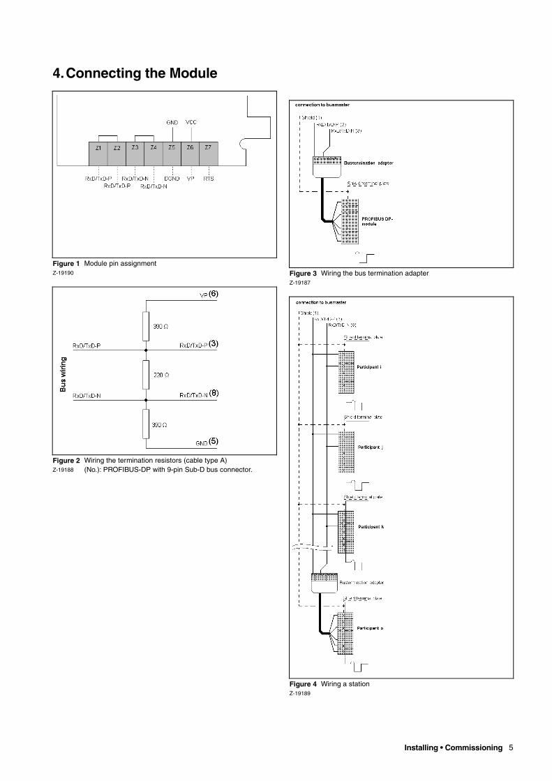
Figure 1 Module pin assignmentZ-19190
Figure 2 Wiring the termination resistors (cable type A)Z-19188 (No.): PROFIBUS-DP with 9-pin Sub-D bus connector.
Figure 3 Wiring the bus termination adapterZ-19187
Figure 4 Wiring a stationZ-19189
6 Installing • Commissioning
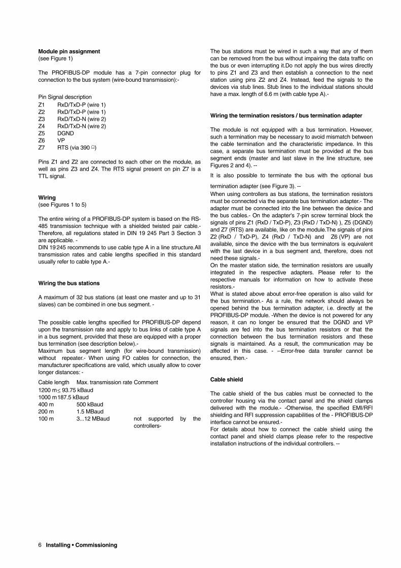
Module pin assignment(see Figure 1)
The PROFIBUS-DP module has a 7-pin connector plug forconnection to the bus system (wire-bound transmission):-
Pin Signal descriptionZ1 RxD/TxD-P (wire 1)Z2 RxD/TxD-P (wire 1)Z3 RxD/TxD-N (wire 2)Z4 RxD/TxD-N (wire 2)Z5 DGNDZ6 VPZ7 RTS (via 390 Ω)
Pins Z1 and Z2 are connected to each other on the module, aswell as pins Z3 and Z4. The RTS signal present on pin Z7 is aTTL signal.
Wiring(see Figures 1 to 5)
The entire wiring of a PROFIBUS-DP system is based on the RS-485 transmission technique with a shielded twisted pair cable.-Therefore, all regulations stated in DIN 19 245 Part 3 Section 3are applicable. - DIN 19 245 recommends to use cable type A in a line structure.Alltransmission rates and cable lengths specified in this standardusually refer to cable type A.-
Wiring the bus stations
A maximum of 32 bus stations (at least one master and up to 31slaves) can be combined in one bus segment. -
The possible cable lengths specified for PROFIBUS-DP dependupon the transmission rate and apply to bus links of cable type Ain a bus segment, provided that these are equipped with a properbus termination (see description below).-Maximum bus segment length (for wire-bound transmission)without repeater.- When using FO cables for connection, themanufacturer specifications are valid, which usually allow to coverlonger distances: -
Cable length Max. transmission rate Comment1200 m≤ 93.75 kBaud1000 m187.5 kBaud400 m 500 kBaud200 m 1.5 MBaud100 m 3...12 MBaud not supported by the
controllers-
The bus stations must be wired in such a way that any of themcan be removed from the bus without impairing the data traffic onthe bus or even interrupting it.Do not apply the bus wires directlyto pins Z1 and Z3 and then establish a connection to the nextstation using pins Z2 and Z4. Instead, feed the signals to thedevices via stub lines. Stub lines to the individual stations shouldhave a max. length of 6.6 m (with cable type A).-
Wiring the termination resistors / bus termination adapter
The module is not equipped with a bus termination. However,such a termination may be necessary to avoid mismatch betweenthe cable termination and the characteristic impedance. In thiscase, a separate bus termination must be provided at the bussegment ends (master and last slave in the line structure, seeFigures 2 and 4). --
It is also possible to terminate the bus with the optional bus
termination adapter (see Figure 3). --When using controllers as bus stations, the termination resistorsmust be connected via the separate bus termination adapter.- Theadapter must be connected into the line between the device andthe bus cables.- On the adapter's 7-pin screw terminal block thesignals of pins Z1 (RxD / TxD-P), Z3 (RxD / TxD-N) ), Z5 (DGND)and Z7 (RTS) are available, like on the module.The signals of pinsZ2 (RxD / TxD-P), Z4 (RxD / TxD-N) and Z6 (VP) are notavailable, since the device with the bus terminators is equivalentwith the last device in a bus segment and, therefore, does notneed these signals.-On the master station side, the termination resistors are usuallyintegrated in the respective adapters. Please refer to therespective manuals for information on how to activate theseresistors.-What is stated above about error-free operation is also valid forthe bus termination.- As a rule, the network should always beopened behind the bus termination adapter, i.e. directly at thePROFIBUS-DP module. -When the device is not powered for anyreason, it can no longer be ensured that the DGND and VPsignals are fed into the bus termination resistors or that theconnection between the bus termination resistors and thesesignals is maintained. As a result, the communication may beaffected in this case. - --Error-free data transfer cannot beensured, then.-
Cable shield
The cable shield of the bus cables must be connected to thecontroller housing via the contact panel and the shield clampsdelivered with the module.- -Otherwise, the specified EMI/RFIshielding and RFI suppression capabilities of the - PROFIBUS-DPinterface cannot be ensured.-For details about how to connect the cable shield using thecontact panel and shield clamps please refer to the respectiveinstallation instructions of the individual controllers. --
Installing • Commissioning 7
RS-485 Repeaters
If more than 32 stations are connected to the bus, the signals onthe bus have to be amplified by RS-485 repeaters. -
Note that one repeater is needed for every 31 stations (master
plus slaves), since the RS-485 repeater itself is to be considered
as a bus station as well.Every section up to the first repeater or between two repeaters iscalled a bus segment. -
Repeaters are also required if a bus segment needed for therespective application cannot be realized using the possible cablelengths (given by the baud rate). - Refer to the RS-485 repeaterdocumentation for the possible cable lengths.- The max. numberof RS-485 repeaters that can be connected in series is alsospecified in these manuals. -Since RS-485 repeaters are usually the first or last station in abus network, they must be provided with the respectivetermination resistors to terminate the bus properly.
Station address
The station address of the device, i.e. of a DP slave on acommunication bus, is entered in the controller list configurationunder Device/Communication/Functional block 30/DPaddress/Inquiry 06.-- Any number between 1 and 125 is a validentry. Automatic address assignment through the master is notsupported.- This inquiry can only be selected with the devicefirmware revisions for library 3.5.0. The other inquiries infunctional block 30 are used for setting up the communication viathe RS-232 and RS-485 interface modules.
Additional recommendations related to installation and configuration
During the commissioning phase it may become necessary toincrease the storage areas for the input and output data due toadditional variables. Therefore, it is recommended to reserve abigger area already when making the slave-specific configuration.Then it is only necessary to change the slave-specific parametersettings.
It is not always possible to write on the variable indices while thedevice is working. When the device is in configuration mode(menu level 2) in the menu system, the index can be written, butthe PROFIBUS-DP module does not transmit the value to thedevice.-
Lateral Communication
If an optional RS-232 or RS-485 interface module has beeninstalled in the controller, lateral communication programmablewithin the free configuration can be run in parallel with PROFIBUS-DP communication. - The necessary communicationparameters have to be set by answering the inquiries of functionalblock 30 in the device configuration, dedicated to lateralcommunication.
Lateral communication has been configured in such a way thatsimultaneous writing on variables via lateral communication andPROFIBUS-DP communication is not possible. ---Therefore, nospecial attention has to be paid to a possible interlocking of thesetwo functions. -
8 Installing • Commissioning
MODBUS Communication
If an optional RS-232 or RS-485 interface module has beeninstalled in the controller, MODBUS communication can be run inparallel with communication via the PROFIBUS-DP interface. --The necessary communication parameters have to be set byanswering the inquiries of functional block 30 in the deviceconfiguration, dedicated to MODBUS communication.--Since simultaneous write access via MODBUS communicationand PROFIBUS-DP communication to variables or onlineparameters of the devices is possible, the last processedcommand enters its value. ---- None of the two communicationshas priority over the other. --
In case of cyclic write access to variables via PROFIBUS-DP,write access via MODBUS communication to the same variablehas no permanent effect. --It is recommended to avoid cyclic write access to onlineparameters, since this would cause various write actions to thenonvolatile flash memory. --- After around 100,000 write actionsthis will lead to malfunctions of the flash EPROM. --

Operation 9
OperationDescription
Every PROFIBUS-DP slave type must have an individualidentification number (ID number). -- The PROFIBUS-DP masterneeds this ID number to identify the connected device type. -Before starting cyclic data transmission, the PROFIBUS-DPmaster compares the device ID number with the default numberin the engineering data. -- Data transmission is only started if theproper device types with the correct station addresses have beenconnected to the bus, and if the parameter and configuration datafrom the slave have been checked and are correct. --- Thisensures a good protection against engineering errors. -
The same ID number is valid for the controllers, and is assigned
to them in factory.- As a result, the PROFIBUS-DP module can
be used in all devices.The device database files (GSD files) contain a description for thesupport of the basic PROFIBUS-DP services, and informationabout the size of the input and output data blocks transmitted viathe bus. - These data blocks are defined in the GSD files asmodules for communication with the controllers. -
Modular Slave
The device database file contains data that describe the so-calledmodules. - This module description is no description of theoptional input/output modules that can be added to the individualdevices at a later time. ---
Instead, it contains information about the storage areas ofdifferent sizes for the input and output data. --These storage areasare referred to as modules. - Configuration data can be createdfrom these modules as a part of the bus configuration,communicating to the relevant slave the number of cyclic databytes or words (2 bytes) it will receive from the master, or thenumber of cyclic data bytes or words which the master expects toreceive from the slave.- - Up to 16 modules for input and outputdefinition can be stored in a slave-specific configuration.- ThePROFIBUS-DP master configuration tool prevents that thismaximum value is exceeded.
Important Information about Services
Freeze and Sync services are supported, as specified in the GSDfile. -The PROFIBUS-DP module for the controllers supports the"Auto_Baud_Supp" service for automatic adjustment of thetransmission rate on the bus. PROFIBUS-DP does not require anytransmission rate adjustment in the device configuration. -Since no automatic station address assignment takes placeduring operation, the address must be defined in the deviceconfiguration.
The "AUTO_CLEAR" function usually realized for PROFIBUS-DPslaves is not supported. As a result, the output values retain theirvalue when the communication is interrupted, and are not reset to0. Usually, the digital and analog outputs retain their values aswell, depending on the device configuration.
10 Operation
Cyclic Operation
Usually, PROFIBUS-DP communication is cyclical.- This meansthat the data is transmitted between the master and the slave in aspecial, permanently repeated rhythm.- The number of bytestransmitted from the master to the slave (output data) or from theslave to the master (input data) is the same for every transferaction. - However, the volume of the input data is different fromthat of the output data. This situation can only be changed through reconfiguration, orthrough redefinition of parameters. --When PROFIBUS-DP communication was defined, a maximumsize was fixed for the data blocks that can be transmitted from themaster to the slave and vice versa. - The exact number of bytesthat can be transferred in the respective direction is specified inthe device database file (GSD file) of every device designed forPROFIBUS-DP communication.- With controllers, usually 224input data bytes and 64 output data bytes can be transmitted. -
However, up to 2000 different data are available for reading/writingwith most of these devices. Therefore, the user must define in anapplication-specific description the data that are to becommunicated in the input or output data. ---
This application-specific description is written into the
slave-specific parameter data set ("User_Prm_Data") of the
master. - Up to 224 bytes can be entered here. The first 4 bytes
are already predefined. This means that 220 bytes are available
for definition.Usually, indices in 16-bit integer format are used to define whichdata is to be read/written cyclically.---- Please refer to section"Addressing the Data" for details about index assignment to thevariables and online parameters in both decimal and hexadecimalformat.--- Up to 110 variables and online parameters can bedefined in the 220 available bytes.-
Reading Values (Cyclically)
The description for cyclic reading of one or more values can bedefined in the "User_Prm_Data" data of the respective slavethrough several subsequent indices. - The order is very important.The input data are transmitted from the master to the slave in thesame order in which they are defined in the "User_Prm_Data".---
ExampleThe measuring values from the four analog inputs of the firstmodule are to be read cyclically in the order .AE11, .AE12, .AE13,and .AE14.
Variable Data type PROFIBUS-DP index (decimal).AE11 REAL 5.AE12 REAL 7.AE13 REAL 9
.AE14 REAL 11From this results for "User_Prm_Data":
User_Prm_Data = .., .., .., .., 5, 7, 9, 11 End_User_Prm_DataThe 4 bytes at the beginning of the slave-specific parameter data(.., .., .., ..,) are predefined and must not be used for definingvariables. - Refer to section "Peculiarities of "User_Prm_Data"" fordetails. -
As a result, the slave will return 16 bytes to the master. - The first
4 bytes contain the value of variable .AE11 in REAL format. - The
second 4 bytes contain the value of variable .AE12 in REAL
format, and so on. -This example assumes that the necessary configurationinformation for the bus system has been provided without errors inthe slave-specific data of the master, and has been accepted bythe addressed slave. ---Refer to section "Addressing the Data" for the assignment of theindices to the variables and online parameters.-
Operation 11
Writing Values (Cyclically)
The description for cyclic writing of one or more values can bedefined in the "User_Prm_Data" of the respective slave throughseveral subsequent indices. --- Contrary to cyclic reading, theindices must be entered with a negative sign in the"User_Prm_Data". -- The order is very important. The output dataare transmitted from the master to the slave in the same order inwhich they are defined in the "User_Prm_Data".
ExampleThe computer output variables of the first two control loops are tobe written cyclically, in the order .L1_YCOMPUTER and.L2_YCOMPUTER. -Variable Data type PROFIBUS-DP index
(decimal).L1_YCOMPUTER REAL 255
.L2_YCOMPUTER REAL 405From this results for "User_Prm_Data":
User_Prm_Data = .., .., .., .., -255, -405 End_User_Prm_DataThe 4 bytes at the beginning of the slave-specific parameter data(.., .., .., ..,) are predefined and must not be used for definingvariables. - Refer to section "Peculiarities of "User_Prm_Data"" fordetails. -
To ensure error-free operation, the master must transmit 8 bytes
to the addressed slave. In the first 4 bytes the value for the
.L1_YCOMPUTER variable must be entered (in REAL format),
and in the second 4 bytes the value for the .L2_YCOMPUTER
variable (REAL format as well). -This example assumes that the necessary configurationinformation for the bus system has been provided without errors inthe slave-specific data of the master, and has been accepted bythe addressed slave. -Refer to section "Addressing the Data" for details about theassignment of indices to the variables and online parameters, andfor the directives for creating negative indices in hexadecimalformat. --
12 Operation
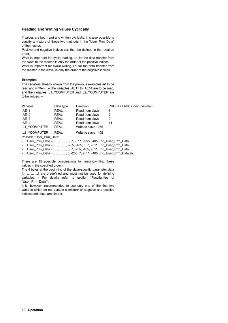
Reading and Writing Values Cyclically
If values are both read and written cyclically, it is also possible tospecify a mixture of these two methods in the "User_Prm_Data"of the master. -Positive and negative indices can then be defined in the requiredorder. -What is important for cyclic reading, i.e. for the data transfer fromthe slave to the master, is only the order of the positive indices. -What is important for cyclic writing, i.e. for the data transfer fromthe master to the slave, is only the order of the negative indices.
ExamplesThe variables already known from the previous examples art to beread and written, i.e. the variables .AE11 to .AE14 are to be read,and the variables .L1_YCOMPUTER and .L2_YCOMPUTER areto be written. --
Variable Data type Direction PROFIBUS-DP index (decimal).AE11 REAL Read from slave 5.AE12 REAL Read from slave 7.AE13 REAL Read from slave 9.AE14 REAL Read from slave 11.L1_YCOMPUTER REAL Write to slave 255
.L2_YCOMPUTER REAL Write to slave 405Possible "User_Prm_Data":- User_Prm_Data = .., .., .., .., 5, 7, 9, 11, -255, -405 End_User_Prm_Data- User_Prm_Data = .., .., .., .., -255, -405, 5, 7, 9, 11 End_User_Prm_Data- User_Prm_Data = .., .., .., .., 5, 7, -255, -405, 9, 11 End_User_Prm_Data- User_Prm_Data = .., .., .., .., 5, -255, 7, 9, 11, -405 End_User_Prm_Data etc.
There are 15 possible combinations for reading/writing thesevalues in the specified order. -The 4 bytes at the beginning of the slave-specific parameter data(.., .., .., ..,) are predefined and must not be used for definingvariables. - For details refer to section "Peculiarities of"User_Prm_Data"". -It is, however, recommended to use only one of the first twovariants which do not contain a mixture of negative and positiveindices and, thus, are clearer. --
Operation 13
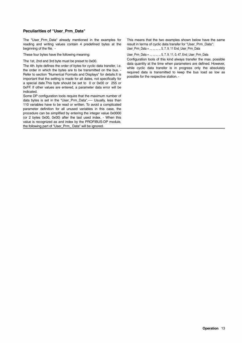
Peculiarities of "User_Prm_Data"
The "User_Prm_Data" already mentioned in the examples forreading and writing values contain 4 predefined bytes at thebeginning of the file. -
These four bytes have the following meaning:
The 1st, 2nd and 3rd byte must be preset to 0x00.The 4th. byte defines the order of bytes for cyclic data transfer, i.e.the order in which the bytes are to be transmitted on the bus. -Refer to section "Numerical Formats and Displays" for details.It isimportant that the setting is made for all dates, not specifically fora special date.This byte should be set to 0 or 0x00 or 255 or0xFF. If other values are entered, a parameter data error will beindicated. Some DP configuration tools require that the maximum number ofdata bytes is set in the "User_Prm_Data".---- Usually, less than110 variables have to be read or written. To avoid a complicatedparameter definition for all unused variables in this case, theprocedure can be simplified by entering the integer value 0x0000(or 2 bytes 0x00, 0x00) after the last used index. - When thisvalue is recognized as and index by the PROFIBUS-DP module,the following part of "User_Prm_ Data" will be ignored.
This means that the two examples shown below have the sameresult in terms of cyclic data transfer for "User_Prm_Data": User_Prm_Data = .., .., .., .., 5, 7, 9, 11 End_User_Prm_Data
User_Prm_Data = .., .., .., .., 5, 7, 9, 11, 0, 47, End_User_Prm_DataConfiguration tools of this kind always transfer the max. possibledata quantity at the time when parameters are defined. However,while cyclic data transfer is in progress only the absolutelyrequired data is transmitted to keep the bus load as low aspossible for the respective station. -
14 Operation
Acyclic Operation
The descriptions above refer to cyclic, i.e. continuously repeateddata transfer. If, however, values like control parameters orsetpoints have to be written sporadically for these devices, thecyclic system can no longer be used. - Therefore, PROFIBUS-DPoffers for these devices an interface for acyclic operation.This kind of operation permits both acyclic writing and acyclicreading of data. -
First of all you have to find out if the used PROFIBUS-DP masteralready supports the standardized services of Version 1 calledPROFIBUS-DP V1.-- Otherwise, you can also use the realizationwithout PROFIBUS-DP V1 which is described later in this manual.
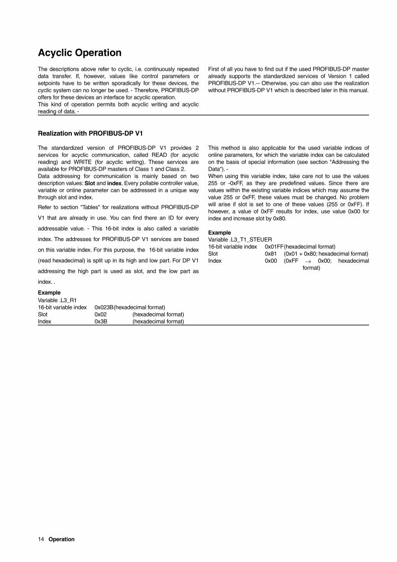
Realization with PROFIBUS-DP V1
The standardized version of PROFIBUS-DP V1 provides 2services for acyclic communication, called READ (for acyclicreading) and WRITE (for acyclic writing). These services areavailable for PROFIBUS-DP masters of Class 1 and Class 2.Data addressing for communication is mainly based on twodescription values: Slot and index. Every pollable controller value,variable or online parameter can be addressed in a unique waythrough slot and index.
Refer to section "Tables" for realizations without PROFIBUS-DP
V1 that are already in use. You can find there an ID for every
addressable value. - This 16-bit index is also called a variable
index. The addresses for PROFIBUS-DP V1 services are based
on this variable index. For this purpose, the 16-bit variable index
(read hexadecimal) is split up in its high and low part. For DP V1
addressing the high part is used as slot, and the low part as
index. .
ExampleVariable .L3_R116-bit variable index 0x023B(hexadecimal format)Slot 0x02 (hexadecimal format)Index 0x3B (hexadecimal format)
This method is also applicable for the used variable indices ofonline parameters, for which the variable index can be calculatedon the basis of special information (see section "Addressing theData"). -When using this variable index, take care not to use the values255 or -0xFF, as they are predefined values. Since there arevalues within the existing variable indices which may assume thevalue 255 or 0xFF, these values must be changed. No problemwill arise if slot is set to one of these values (255 or 0xFF). Ifhowever, a value of 0xFF results for index, use value 0x00 forindex and increase slot by 0x80.
ExampleVariable .L3_T1_STEUER16-bit variable index 0x01FF(hexadecimal format)Slot 0x81 (0x01 + 0x80; hexadecimal format)Index 0x00 (0xFF → 0x00; hexadecimal
format)
Operation 15
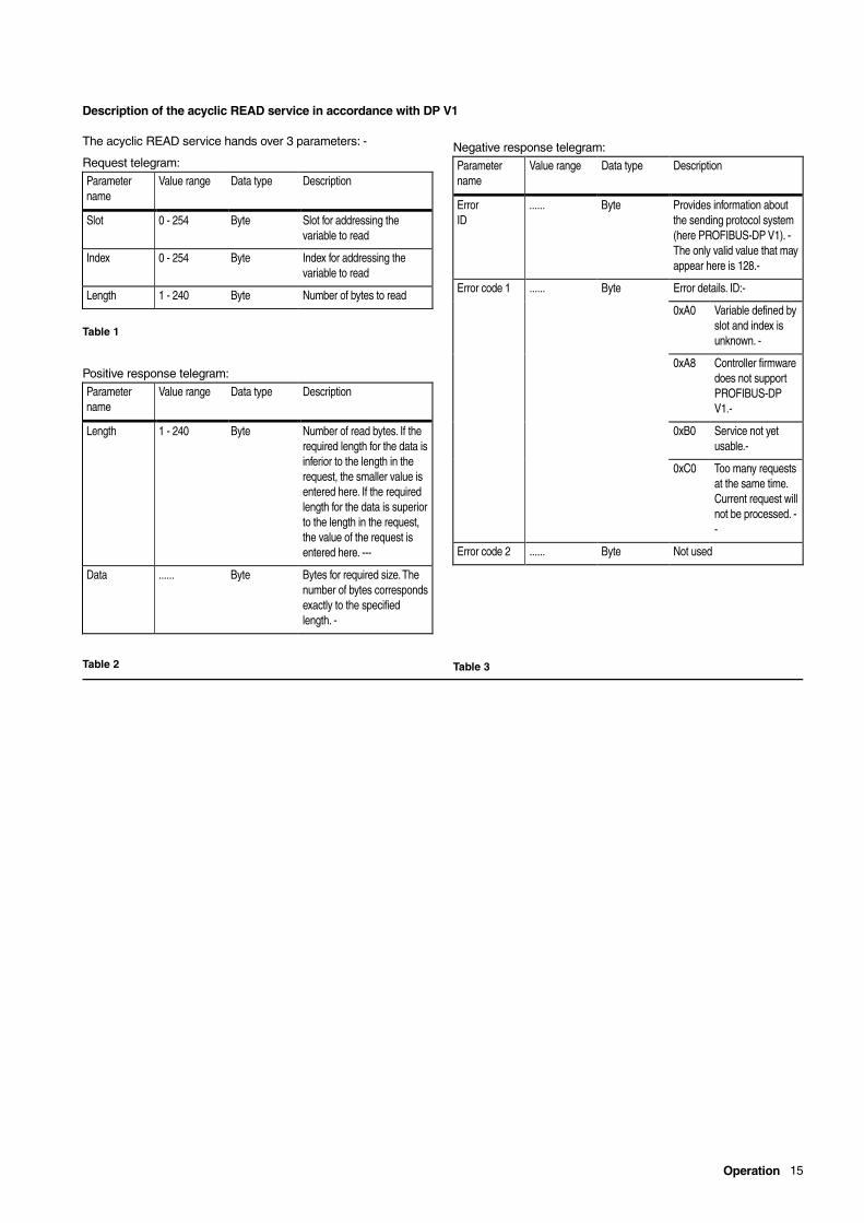
Description of the acyclic READ service in accordance with DP V1
The acyclic READ service hands over 3 parameters: -
Request telegram:
Table 1
Positive response telegram:
Table 2
Negative response telegram:
Table 3
Parametername
Value range Data type Description
Slot 0 - 254 Byte Slot for addressing thevariable to read
Index 0 - 254 Byte Index for addressing thevariable to read
Length 1 - 240 Byte Number of bytes to read
Parametername
Value range Data type Description
Length 1 - 240 Byte Number of read bytes. If therequired length for the data isinferior to the length in therequest, the smaller value isentered here. If the requiredlength for the data is superiorto the length in the request,the value of the request isentered here. ---
Data ...... Byte Bytes for required size. Thenumber of bytes correspondsexactly to the specifiedlength. -
Parametername
Value range Data type Description
ErrorID
...... Byte Provides information aboutthe sending protocol system(here PROFIBUS-DP V1). -The only valid value that mayappear here is 128.-
Error code 1 ...... Byte Error details. ID:-
0xA0 Variable defined byslot and index isunknown. -
0xA8 Controller firmwaredoes not supportPROFIBUS-DPV1.-
0xB0 Service not yetusable.-
0xC0 Too many requestsat the same time.Current request willnot be processed. --
Error code 2 ...... Byte Not used

16 Operation
Description of the acyclic WRITE service in accordance with DP V1
The acyclic write service always derives the slot and index fromthe hexadecimal 16-bit variable index for reading. - Fourparameters are handed over in the request telegram:
Request telegram:
Table 4
Positive response telegram:
Table 5
Negative response telegram:
Table 6
Parametername
Value range Data type Description
Slot 0 - 254 Byte Slot for addressing thevariable to write.
Index 0 - 254 Byte Index for addressing thevariable to write.
Length 1 - 240 Byte Number of bytes to write-
Data ...... Bytes Bytes for value of variable towrite. It is impossible tospecify more bytes thandefined by length.-
Parametername
Value range Data type Description
Length 1 - 240 Byte Number of written bytes. Ifthe required length for thedata is inferior than therequested length, thenegative value is enteredhere. If the required length forthe data is superior to therequested length, therequested length is enteredhere. --
Parametername
Value range Data type Description
ErrorID
...... Byte Provides information aboutthe sending protocol system(here PROFIBUS-DP V1).-The only valid value that mayappear here is 128.-
Error code 1 ...... Byte Error details. ID: -
0xA1 Variable defined byslot and index isunknown.-
0xA8 Controller firmwaredoes not supportPROFIBUS-DPV1.-
0xB0 Service not yetusable.-
0xC0 Too many requestsat the same time.Current request willnot be processed. --
Error code 2 ...... Byte Not used
Operation 17
Realization without PROFIBUS-DP V1
Acyclic data transmission without PROFIBUS-DP V1 is based onthe usage of data blocks in the input and output data cyclicallytransmitted to a specific slave. -- These data blocks are used as"envelopes" in which data can be entered if required and fromwhich results can be read. Since these data blocks aretransmitted cyclically, this method slightly increases thetransmission time, but this increase is negligible. There are modules in the device database file that are tailored tothis application - like for the slave-specific configuration data forcyclic operation. -- A total of 2 modules is available for acyclictransmission. One module is dedicated to writing, and one toreading of data.
Data blocks in the input and output data are reserved for the readand write services, regardless which of the services is selected. -The service is entered in the output data and transmitted to theslave. The result is transmitted to the master in the input data. Up to 4 acyclic services can be used in parallel for everycontroller. To achieve this, the necessary modules must beentered together in the slave-specific configuration data. --
18 Operation
Description of the Write Service
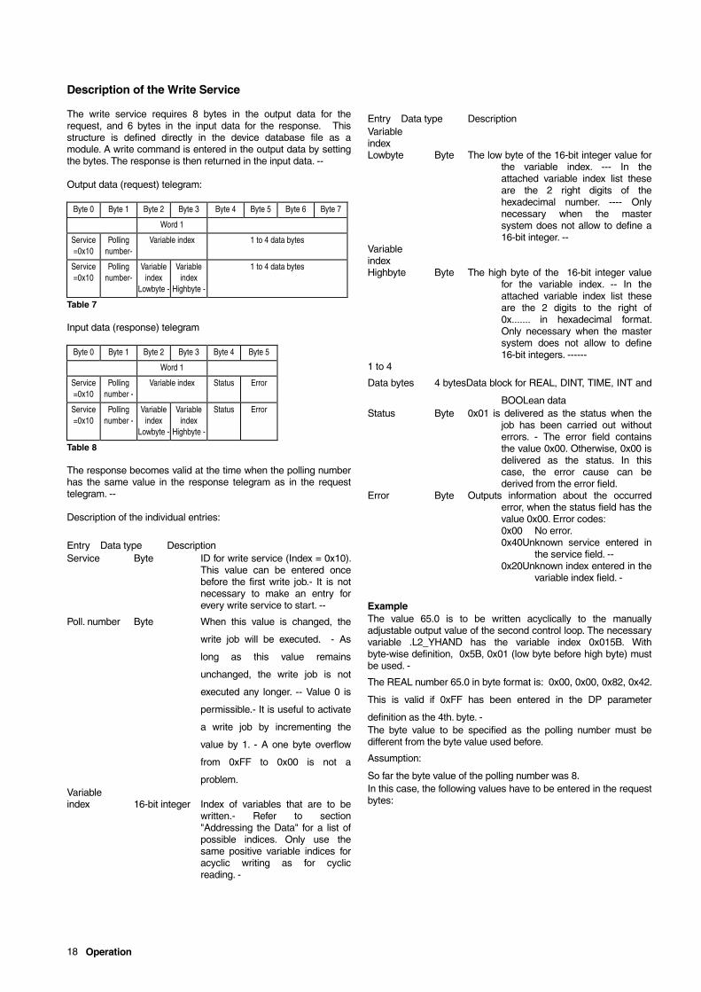
The write service requires 8 bytes in the output data for therequest, and 6 bytes in the input data for the response. Thisstructure is defined directly in the device database file as amodule. A write command is entered in the output data by settingthe bytes. The response is then returned in the input data. --
Output data (request) telegram:
Table 7
Input data (response) telegram
Table 8
The response becomes valid at the time when the polling numberhas the same value in the response telegram as in the requesttelegram. --
Description of the individual entries:
Entry Data type DescriptionService Byte ID for write service (Index = 0x10).
This value can be entered oncebefore the first write job.- It is notnecessary to make an entry forevery write service to start. --
Poll. number Byte When this value is changed, the
write job will be executed. - As
long as this value remains
unchanged, the write job is not
executed any longer. -- Value 0 is
permissible.- It is useful to activate
a write job by incrementing the
value by 1. - A one byte overflow
from 0xFF to 0x00 is not a
problem.Variableindex 16-bit integer Index of variables that are to be
written.- Refer to section"Addressing the Data" for a list ofpossible indices. Only use thesame positive variable indices foracyclic writing as for cyclicreading. -
Entry Data type DescriptionVariableindexLowbyte Byte The low byte of the 16-bit integer value for
the variable index. --- In theattached variable index list theseare the 2 right digits of thehexadecimal number. ---- Onlynecessary when the mastersystem does not allow to define a16-bit integer. --
VariableindexHighbyte Byte The high byte of the 16-bit integer value
for the variable index. -- In theattached variable index list theseare the 2 digits to the right of0x....... in hexadecimal format.Only necessary when the mastersystem does not allow to define16-bit integers. ------
1 to 4
Data bytes 4 bytesData block for REAL, DINT, TIME, INT and
BOOLean dataStatus Byte 0x01 is delivered as the status when the
job has been carried out withouterrors. - The error field containsthe value 0x00. Otherwise, 0x00 isdelivered as the status. In thiscase, the error cause can bederived from the error field.
Error Byte Outputs information about the occurrederror, when the status field has thevalue 0x00. Error codes:0x00 No error.0x40Unknown service entered in
the service field. --0x20Unknown index entered in the
variable index field. -
ExampleThe value 65.0 is to be written acyclically to the manuallyadjustable output value of the second control loop. The necessaryvariable .L2_YHAND has the variable index 0x015B. Withbyte-wise definition, 0x5B, 0x01 (low byte before high byte) mustbe used. -
The REAL number 65.0 in byte format is: 0x00, 0x00, 0x82, 0x42.
This is valid if 0xFF has been entered in the DP parameter
definition as the 4th. byte. -The byte value to be specified as the polling number must bedifferent from the byte value used before.
Assumption:
So far the byte value of the polling number was 8.In this case, the following values have to be entered in the requestbytes:
Byte 0 Byte 1 Byte 2 Byte 3 Byte 4 Byte 5 Byte 6 Byte 7
Word 1
Service=0x10
Pollingnumber-
Variable index 1 to 4 data bytes
Service=0x10
Pollingnumber-
Variableindex
Lowbyte -
Variableindex
Highbyte -
1 to 4 data bytes
Byte 0 Byte 1 Byte 2 Byte 3 Byte 4 Byte 5
Word 1
Service=0x10
Pollingnumber -
Variable index Status Error
Service=0x10
Pollingnumber -
Variableindex
Lowbyte -
Variableindex
Highbyte -
Status Error
Operation 19
Request:0x10, 0x08, 0x5B, 0x01, 0x..., 0x..., 0x..., 0x...
(Variable index in bytes , "0x..." means any value for the four data
bytes)Then the value 65.0 must be entered in the data bytes:0x10, 0x8B, 0x5B, 0x01, 0x00, 0x00, 0x82, 0x42
(Variable index in bytes)When all bytes have been entered (except for the second byte),the polling number can be incremented:0x10, 0x09, 0x5B, 0x01, 0x00, 0x00, 0x82, 0x42(Variable index in bytes)
Response (provided that no errors have occurred):0x10, 0x08, 0x5B, 0x01, 0x01, 0x00
(Variable index in bytes)The modified polling number is returned only when the acyclicwrite job has been fully processed by the DP slave. --0x10, 0x09, 0x5B, 0x01, 0x010, 0x00
(Variable index in bytes)Since the polling number (2nd byte) is then identical with thetransmitted polling number, the result can be evaluated. -If the status (5th byte) is correct, the value 0x01 (as indicatedhere) and the value 0x00 (6th. byte, error) are returned. - Then thenext variable index can be written, or a new value can be enteredfor the same variable index.
If the index is wrong (e.g. if the connected controller does not yetknow the index), a static diagnostic information is additionallytransmitted to the DP master. ---The DP master then has to pollthe diagnostic function until the DP slave does no longer transmitthis diagnostic data. ---

20 Operation
Description of the Read Service
The read service requires 4 bytes in the output data for therequest, and 10 bytes in the input data for the response. Thisstructure is defined directly in the device database file as amodule. A read job is written in the output data, the result isreturned in the input data. --
Output data (request) telegram:
Table 9
Input data (response) telegram
Table 10
The response becomes valid at the time when the polling numberhas the same value in the response telegram as in the requesttelegram.-
Description of the individual entries:
Entry Data type Description
Service Byte ID for the read service
(Index = 0x20)Polling number Byte When this value is changed, the
read job will be executed. - As longas this value remains unchanged,the read job is not executed anylonger.- Value 0 is permissible.- Itis useful to activate a read job byincrementing the value by 1. - Aone byte overflow from 0xFF to0x00 is not a problem. -
Variableindex 16-bit integer Index of the variable that is to be
read. - Refer to section"Addressing the Data" for a list ofpossible indices.
Variableindex
Lowbyte Byte The low byte of the 16-bit integer value for
the variable index.-- In the
attached variable index list these
are the 2 right digits of the
hexadecimal number.---- Only
necessary when the master
system does not allow to define a
16-bit integer. --VariableindexHighbyte Byte The high byte of the 16-bit integer value for
the variable index. -- In theattached variable index list theseare the 2 digits to the right of0x....... in the hexadecimal numberformat. Only necessary when themaster system does not allow todefine 16-bit integers.------
Status Byte 0x01 is delivered as the status when thejob has been carried out withouterrors. - The error field containsthe value 0x00. Otherwise, 0x00 isdelivered as the status. In thiscase, the error cause can bederived from the error field.
Error Byte Outputs information about the occurrederror, when the status field has thevalue 0x00. Error codes:0x00 No error occurred0x40Unknown service entered in
the service field. --0x20Unknown index entered in the
variable index field.-
1 to 4
Data bytes 4 bytesData block for REAL, DINT, TIME, INT and
BOOLean data.
Example
The output value of the 3rd control loop is to be read acyclically.
The required variable .L3_PID_Y_OUT has the variable index
0x0367. The byte value for the polling number must be different
from the byte value used before. A REAL number is read as the
requested value. -
Request:
0x20, byte value, 0x0367 (variable index as 16-bit integer)
0x20, byte value, 0x67, 0x03 (variable index in bytes)
Response (if processed without errors):0x20, byte value, 0x0367, 0x01, 0x00 , 4 bytes for value
(Variable index as 16-bit integer)0x20, byte value, 0x67, 0x03, 0x01, 0x00, 4 bytes for value
(Variable index in bytes)The 4 bytes for the values are to be interpreted in accordancewith section "Numerical Formats and Displays". --
Byte 0 Byte 1 Byte 2 Byte 3
Word 1
Service=0x20
Pollingnumber -
Variable index
Service=0x20
Pollingnumber -
Variableindex
Lowbyte -
Variableindex
Highbyte -
Byte 0 Byte 1 Byte 2 Byte 3 Byte 4 Byte 5 Byte 6 Byte 7 Byte 8 Byte 9
Word 1
Service=0x20
PollingNo. -
Variable index Status Error 1 to 4 data bytes
Service=0x20
PollingNo. -
Var.index
Lowbyte--
Var.index
Highbyte--
Status Error 1 to 4 data bytes
Operation 21
Configuration Instructions
A description which specifies the size of the required storageareas is required for error-free cyclic data transmission to/from thedevices, in addition to the slave-specific parameter information. --This slave-specific description is called PROFIBUS configuration.- -When the slave is changed over to cyclic data transmission, thedata blocks defined in the slave-specific configuration aretransmitted as input and output data bytes on the bus. ---Thismeans that the size of the data blocks is an important factor -besides the transmission rate - which determines how often dataexchange with all bus stations is performed. - The smaller thetransported data packages are, the more often a station can becontacted. -The data blocks are built up from the modules specified in thedevice database file (GSD file). These modules are split up inthree groups: - The first group contains all modules defining thesize of the input data blocks, the second group is made up of allmodules specifying the size of the output data blocks, and thethird groups comprises the modules for acyclic transmission. -
It is recommended to calculate the required sizes for the input and
the output data from the data types of the cyclically read or written
variables when combining the necessary modules. -- -The configuration data can then be derived from the individualmodules. - It is recommended to calculate a reserve for the inputdata, since it may turn out in the commissioning phase that moredata is needed from the connected devices. -The modules for the input and output data blocks can becombined in an arbitrary order when selecting them using the device database and a configuration tool. -- Therefore, it isrecommended to select first all modules for the input data blockand then all modules for the output data block, to obtain an openstructure. The configuration can then be extended at a later timeby simply adding modules. The configuration tool useddetermines the efforts required for this task.If the configuration consists of an arbitrary combination of inputand output data blocks, the DP master and the DP slaves forminput and output groups of them. - ----- From this result the sizesof the individual input or output data blocks. When the configured data blocks are bigger than defined by theindices in the parameter definitions for a slave, the connecteddevice will nevertheless accept this constellation. -However, data blocks that are too small and insufficient for dataexchange with the configured variables are considered aserroneous and will be rejected. -- In the commissioning phase, nocyclic data transmission will be performed. Instead, thePROFIBUS-DP master receives the respective diagnostic data.No change-over to cyclic data transmission takes place. ----
ExampleCyclic transmission between a master and a slave is to beestablished. For this purpose, 26 bytes are transmitted from aslave to a master (input data), and the master cyclically returns 1byte to the slave (output data). The necessary storage areas forone read service and one write service are reserved. -----
The sizes of 26 bytes (input data) and 1 byte (output data) wouldhave resulted from the slave-specific parameter definitions. -In reality, 48 bytes are given for the input data (can be extended ata later time by setting the parameters accordingly), and 2 bytesare given for the output data. These data blocks are written in the configuration, in the orderread service, write service, output data, and input data. -Usually, a byte-by-byte definition is used for slave-specificPROFIBUS-DP configuration data. --
A possible configuration would be:
Cfg_Data = 0xC1, 0x03, 0x09, 0x03, 0xC1, 0x07, 0x05, 0x01,
0x60, 0x5F, 0x57This configuration is built up from the following modules:
ModuleData bytes
Read service 0xC1, 0x03, 0x09, 0x03Gives a storage area of 4 bytes for the acyclic read
service as request and 10 bytes as response.Write service 0xC1, 0x07, 0x05, 0x01
Gives a storage area of 8 bytes for the acyclic writeservice as a request and 6 bytes as the response.
Outputdata 0x60
Gives a storage area of 1 word or 2 bytes .
Inputdata 0x5F, 0x57
Gives a storage area of 16 words or 32 bytes (0x5F) andan area of 8 words or 16 bytes (0x57). Since thePROFIBUS-DP module sums up these parts, atotal of 48 bytes is available for input data. ----
Refer to DIN 19245 Part 3 for the exact meaning and function ofthe individual bytes.
PeculiaritiesSome configuration tools for PROFIBUS-DP systems do notpermit the definition of slave-specific configuration data asdescribed above. -- Systems using such tools derive thenecessary configuration data from the data of the connectedcontrollers. - The respective setting for the size of the input andoutput data blocks is read from the configuration in this case. -- -When the DP master integrates a new station in the DPcommunication system, first the configuration data is read, thenthe slave-specific parameters are defined, and then theconfiguration data is returned to the station. ---

22 Operation
The size of these data blocks must be set in the controllerconfiguration for this. This is achieved by answering configurationinquiries 7 and 8 in configuration group "Device", functional block30. Inquiry 7 is used for the factory setting of the input data block,and inquiry 8 for the factory setting of the output data block. It ispossible to set the two data blocks independently of each other toa size between one and 16 words. -- The data blocks fixed withthis are then transmitted cyclically between the DP master andthe DP slave. --- Their size can be defined as described under"Configuration Instructions". -
ImportantThe new/modified setting of these values is only activatedupon controller power on. - Therefore, switch the controlleroff and on again to activate a change. --- -
If this functionality is not needed since the configuration tool doesnot support the entry of slave-specific configuration data, answerboth inquiries with 0 = unused.
Operation 23
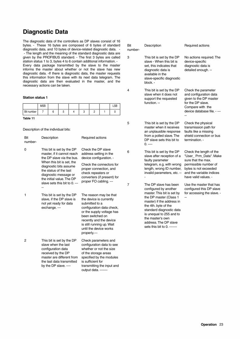
Diagnostic DataThe diagnostic data of the controllers as DP slaves consist of 16bytes. - These 16 bytes are composed of 6 bytes of standarddiagnostic data, and 10 bytes of device-related diagnostic data. - - The length and the meaning of the standard diagnostic data aregiven by the PROFIBUS standard. - The first 3 bytes are calledstation status 1 to 3, bytes 4 to 6 contain additional information. -Every data package transmitted by the slave to the masterinforms the master about whether or not the slave has newdiagnostic data. -If there is diagnostic data, the master requeststhis information from the slave with its next data telegram. Thediagnostic data are then evaluated in the master, and thenecessary actions can be taken.
Station status 1
Table 11
Description of the individual bits:
MSB LSB
Bit number 7 6 5 4 3 2 1 0
Bitnumber-
Description Required actions
0 This bit is set by the DPmaster, if it cannot reachthe DP slave via the bus.When this bit is set, thediagnostic bits assumethe status of the lastdiagnostic message orthe initial value. The DPslave sets this bit to 0. -----
Check the DP slaveaddress setting in thedevice configuration. -
Check the connectors forproper connection, andcheck repeaters orconverters (if present) forproper FO cabling. ---
1 This bit is set by the DPslave, if the DP slave isnot yet ready for dataexchange. ---
The reason may be thatthe device is currentlysubmitted to aconfiguration data check,or the supply voltage hasbeen switched onrecently and the deviceis still running up. Waituntil the device worksproperly.---
2 This bit is set by the DPslave when the lastconfiguration datareceived by the DPmaster are different fromthe last data transmittedby the DP slave. ----
Check parameters andconfiguration data to seewhether or not the sizeof the storage areasspecified by the modulesis sufficient fortransmitting the input andoutput data. -------
Bitnumber-
Description Required actions
3 This bit is set by the DPslave - When this bit isset, this indicates thatdiagnostic data isavailable in theslave-specific diagnosticblock. -
No actions required. Thedevice-specificdiagnostic data isdetailed enough. --
4 This bit is set by the DPslave when it does notsupport the requestedfunction. --
Check the parameterand configuration datagiven to the DP masterfor the DP slave.Compare with thedevice database file. - -----
5 This bit is set by the DPmaster when it receivesan unplausible responsefrom a polled slave. TheDP slave sets this bit to0. ----
Check the physicaltransmission path forfaults like a missingshield connection or bustermination. -
6 This bit is set by the DPslave after reception of afaulty parametertelegram, e.g. with wronglength, wrong ID number,invalid parameters, etc. ---
Check the length of the"User_ Prm_Data". Makesure that the max.permissible number ofbytes is not exceededand the variable indiceshave valid values. -
7 The DP slave has beenconfigured by anothermaster. This bit is set bythe DP master (Class 1master) if the address inthe 4th. byte of thestandard diagnostic datais unequal to 255 and tothe master's ownaddress. The DP slavesets this bit to 0. -------
Use the master that hasconfigured this DP slavefor accessing the slave. ---
24 Operation
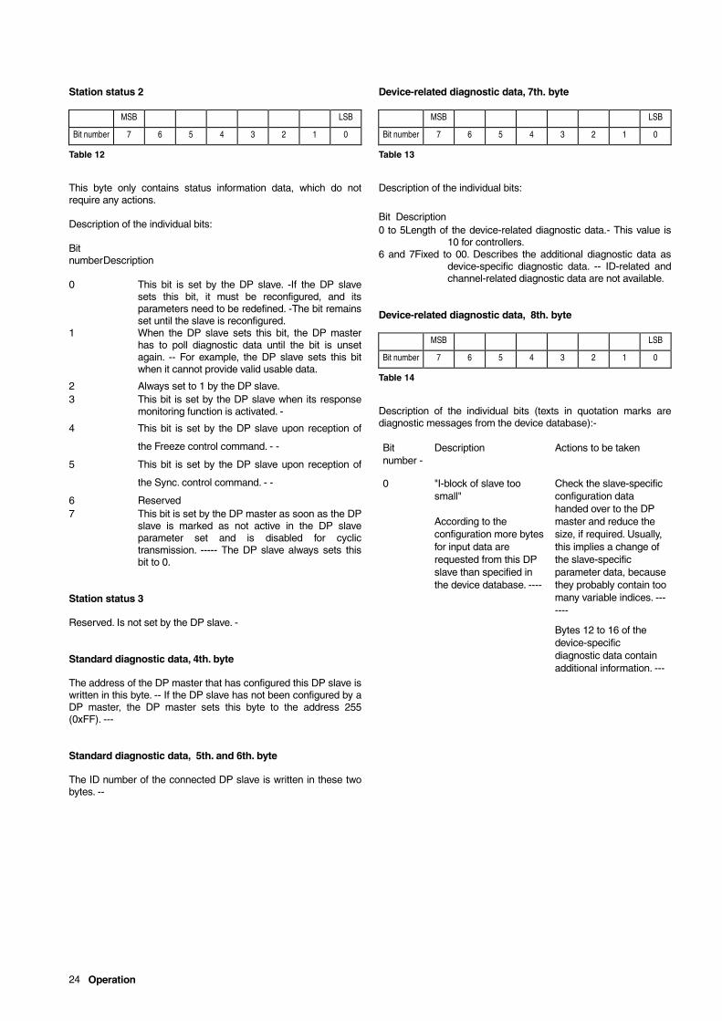
Station status 2
Table 12
This byte only contains status information data, which do notrequire any actions.
Description of the individual bits:
BitnumberDescription
0 This bit is set by the DP slave. -If the DP slavesets this bit, it must be reconfigured, and itsparameters need to be redefined. -The bit remainsset until the slave is reconfigured.
1 When the DP slave sets this bit, the DP masterhas to poll diagnostic data until the bit is unsetagain. -- For example, the DP slave sets this bitwhen it cannot provide valid usable data.
2 Always set to 1 by the DP slave.3 This bit is set by the DP slave when its response
monitoring function is activated. -
4 This bit is set by the DP slave upon reception of
the Freeze control command. - -
5 This bit is set by the DP slave upon reception of
the Sync. control command. - -
6 Reserved7 This bit is set by the DP master as soon as the DP
slave is marked as not active in the DP slaveparameter set and is disabled for cyclictransmission. ----- The DP slave always sets thisbit to 0.
Station status 3
Reserved. Is not set by the DP slave. -
Standard diagnostic data, 4th. byte
The address of the DP master that has configured this DP slave iswritten in this byte. -- If the DP slave has not been configured by aDP master, the DP master sets this byte to the address 255(0xFF). ---
Standard diagnostic data, 5th. and 6th. byte
The ID number of the connected DP slave is written in these twobytes. --
Device-related diagnostic data, 7th. byte
Table 13
Description of the individual bits:
Bit Description0 to 5Length of the device-related diagnostic data.- This value is
10 for controllers. 6 and 7Fixed to 00. Describes the additional diagnostic data as
device-specific diagnostic data. -- ID-related andchannel-related diagnostic data are not available.
Device-related diagnostic data, 8th. byte
Table 14
Description of the individual bits (texts in quotation marks arediagnostic messages from the device database):-
MSB LSB
Bit number 7 6 5 4 3 2 1 0
MSB LSB
Bit number 7 6 5 4 3 2 1 0
MSB LSB
Bit number 7 6 5 4 3 2 1 0
Bitnumber -
Description Actions to be taken
0 "I-block of slave toosmall"
According to theconfiguration more bytesfor input data arerequested from this DPslave than specified inthe device database. ----
Check the slave-specificconfiguration datahanded over to the DPmaster and reduce thesize, if required. Usually,this implies a change ofthe slave-specificparameter data, becausethey probably contain toomany variable indices. -------
Bytes 12 to 16 of thedevice-specificdiagnostic data containadditional information. ---
Operation 25
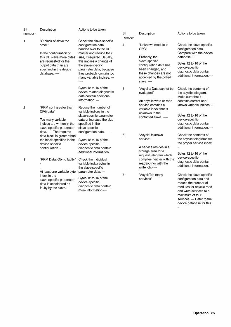
Bitnumber -
Description Actions to be taken
1 "O-block of slave toosmall"
In the configuration ofthis DP slave more bytesare requested for theoutput data than arespecified in the devicedatabase. ----
Check the slave-specificconfiguration datahanded over to the DPmaster and reduce theirsize, if required. Usually,this implies a change ofthe slave-specificparameter data, becausethey probably contain toomany variable indices. -------
Bytes 12 to 16 of thedevice-related diagnosticdata contain additionalinformation. ---
2 "PRM conf greater thanCFG data“
Too many variableindices are written in theslave-specific parameterdata. -----The requireddata block is greater thanthe block specified in thedevice-specificconfiguration. -
Reduce the number ofvariable indices in theslave-specific parameterdata or increase the sizespecified in theslave-specificconfiguration data. --- -
Bytes 12 to 16 of thedevice-specificdiagnostic data containadditional information.
3 "PRM Data: Obj-Id faulty"-
At least one variable byteindex in theslave-specific parameterdata is considered asfaulty by the slave. --
Check the individualvariable index bytes inthe slave-specificparameter data. ---
Bytes 12 to 16 of thedevice-specificdiagnostic data containmore information.---
Bitnumber-
Description Actions to be taken
4 "Unknown module inCFG"
Probably, theslave-specificconfiguration data hasbeen changed, andthese changes are notaccepted by the polledslave. ----
Check the slave-specificconfiguration data.Compare with the devicedatabase. --
Bytes 12 to 16 of thedevice-specificdiagnostic data containadditional information. ---
5 "Acyclic: Data cannot beevaluated"
An acyclic write or readservice contains avariable index that isunknown to thecontacted slave. -----
Check the contents ofthe acyclic telegram.Make sure that itcontains correct andknown variable indices. ---
Bytes 12 to 16 of thedevice-specificdiagnostic data containadditional information. ---
6 "Acycl: Unknownservice"
A service resides in astorage area for arequest telegram whichcomplies neither with theread job nor with thewrite job. ----
Check the contents ofthe acyclic telegrams forthe proper service index.-
Bytes 12 to 16 of thedevice-specificdiagnostic data containadditional information. ---
7 "Acycl: Too manyservices"
Check the slave-specificconfiguration data andreduce the number ofmodules for acyclic readand write services to amaximum of fourservices. --- Refer to thedevice database for this.-

26 Operation
Device-related diagnostic data, 9th. byte
Table 15
Description of the individual bits (texts in quotation marks arediagnostic messages from the device database):-
Device-related diagnostic data, 10th. and 11th. byte
for later extensions, (not yet implemented)
Device-related diagnostic data, 12th. to 16th. byte
This diagnostic data must be interpreted depending on theinformation from the 8th. and 9th. byte. Only if these bytes areunequal to 0x00, evaluable information is given here. -These bytesare not needed for all diagnostic bits
"I-block of slave too small"
Byte 12Always set to 0x00Byte 13, 14 Necessary length of input data block in bytes,
calculated from the configuration data. Themaximum permissible length is specified in thedevice database (GSD file). -
Byte 15, 16 Necessary length of output data block in bytes,calculated from the configuration data. In thisdiagnostic data this value is smaller than the valuespecified in the device database (GSD file).
"O-data block of slave too small"
Byte 12Always set to 0x00Byte 13, 14Necessary length of input data block in bytes,
calculated from the configuration data. In thisdiagnostic data this value is smaller than the valuespecified in the device database (GSD file).
Byte 15, 16Necessary length of output data block in bytes,calculated from the configuration data. Themaximum permissible length is specified in thedevice database (GSD file). -
"PRM conf greater than CFG data"
Byte 12always set to 0x00Byte 13, 14Necessary length of input data block in bytes,
calculated from the configuration data.Byte 15, 16Necessary length of output data block in bytes,
calculated from the configuration data.
"PRM data: Obj-Id faulty“
Byte 12Number of faulty bytes in the "User _Prm_Data". Counterstarts with 1 and counts the bytes.
Byte 13, 14Faulty byte which is unknown to the connected slave.Byte 15, 16Always set to 0x00.
"Unknown module in CFG"
Byte 12Position of faulty module in configuration data, countedfrom the start of the configuration data.-- Counterstarts with 1 and counts the bytes.
Byte 13, 14The bytes specified in the configuration data for thefirst faulty module.
Byte 15, 16 Always set to 0x00.
"Acyclic: Data cannot be evaluated“
Byte 12Service index with a faulty variable index. -Byte 13, 14Number of the acyclic service module in which the
error was found. --Counted from 1 to 4.Byte 15, 16Faulty variable index which is unknown to the
connected slave. -
"Acyclic: Unknown service"
Byte 12Faulty service index for an acyclic service.Byte 13, 14Number of the acyclic service module in which the
error was found. - -Count from 1 to 4.Byte 15, 16 Not used.
MSB LSB
Bit number - 7 6 5 4 3 2 1 0
Bitnumber -
Description Actions to be taken
0 "Controller power failure"
(for later extensions) -
not yet implemented
1 "No communication withcontroller”
The PROFIBUS-DPmodule cannot establish a communication withthe basic device. --
A hardware defect of thedevice or module may bethe reason. Check thebasic device withanother module and themodule with anotherbasic device. ----
2 to 7 for later extensions (notyet implemented)
Operation 27
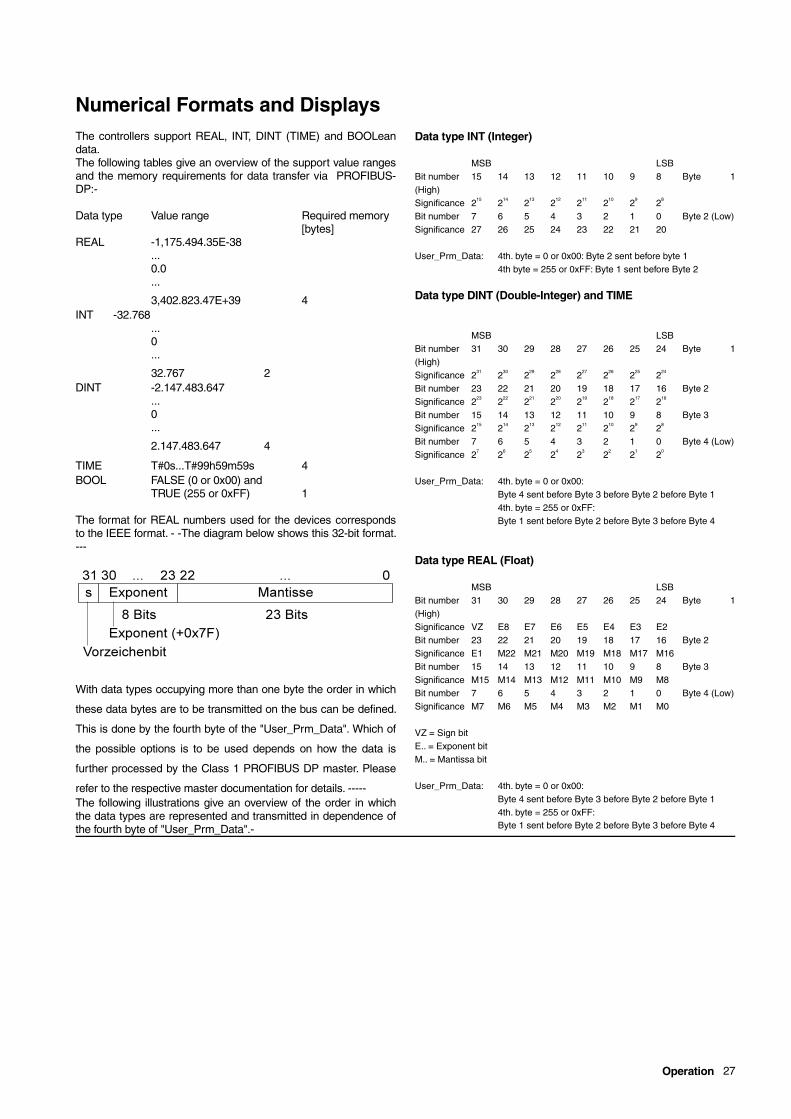
Numerical Formats and DisplaysThe controllers support REAL, INT, DINT (TIME) and BOOLeandata.The following tables give an overview of the support value rangesand the memory requirements for data transfer via PROFIBUS-DP:-
Data type Value range Required memory[bytes]
REAL -1,175.494.35E-38...0.0...
3,402.823.47E+39 4INT -32.768
...0...
32.767 2DINT -2.147.483.647
...0...
2.147.483.647 4
TIME T#0s...T#99h59m59s 4BOOL FALSE (0 or 0x00) and
TRUE (255 or 0xFF) 1
The format for REAL numbers used for the devices correspondsto the IEEE format. - -The diagram below shows this 32-bit format.---
With data types occupying more than one byte the order in which
these data bytes are to be transmitted on the bus can be defined.
This is done by the fourth byte of the "User_Prm_Data". Which of
the possible options is to be used depends on how the data is
further processed by the Class 1 PROFIBUS DP master. Please
refer to the respective master documentation for details. -----The following illustrations give an overview of the order in whichthe data types are represented and transmitted in dependence ofthe fourth byte of "User_Prm_Data".-
Data type INT (Integer)
MSB LSBBit number 15 14 13 12 11 10 9 8 Byte 1(High)Significance 215 214 213 212 211 210 29 28
Bit number 7 6 5 4 3 2 1 0 Byte 2 (Low)Significance 27 26 25 24 23 22 21 20
User_Prm_Data: 4th. byte = 0 or 0x00: Byte 2 sent before byte 14th byte = 255 or 0xFF: Byte 1 sent before Byte 2
Data type DINT (Double-Integer) and TIME
MSB LSBBit number 31 30 29 28 27 26 25 24 Byte 1(High)Significance 231 230 229 228 227 226 225 224
Bit number 23 22 21 20 19 18 17 16 Byte 2Significance 223 222 221 220 219 218 217 216
Bit number 15 14 13 12 11 10 9 8 Byte 3Significance 215 214 213 212 211 210 29 28
Bit number 7 6 5 4 3 2 1 0 Byte 4 (Low)Significance 27 26 25 24 23 22 21 20
User_Prm_Data: 4th. byte = 0 or 0x00:Byte 4 sent before Byte 3 before Byte 2 before Byte 14th. byte = 255 or 0xFF:Byte 1 sent before Byte 2 before Byte 3 before Byte 4
Data type REAL (Float)
MSB LSBBit number 31 30 29 28 27 26 25 24 Byte 1(High)Significance VZ E8 E7 E6 E5 E4 E3 E2Bit number 23 22 21 20 19 18 17 16 Byte 2Significance E1 M22 M21 M20 M19 M18 M17 M16Bit number 15 14 13 12 11 10 9 8 Byte 3Significance M15 M14 M13 M12 M11 M10 M9 M8Bit number 7 6 5 4 3 2 1 0 Byte 4 (Low)Significance M7 M6 M5 M4 M3 M2 M1 M0
VZ = Sign bitE.. = Exponent bitM.. = Mantissa bit
User_Prm_Data: 4th. byte = 0 or 0x00:Byte 4 sent before Byte 3 before Byte 2 before Byte 14th. byte = 255 or 0xFF:Byte 1 sent before Byte 2 before Byte 3 before Byte 4
28 Operation
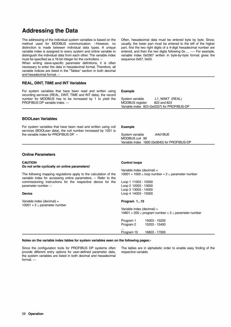
Addressing the DataThe addressing of the individual system variables is based on themethod used for MODBUS communication. --However, nodistinction is made between individual data types. A uniquevariable index is assigned to every system and online variable todistinguish the individual data from each other. The variable indexmust be specified as a 16-bit integer for the controllers. --When writing slave-specific parameter definitions, it is oftennecessary to enter the data in hexadecimal format. Therefore, allvariable indices are listed in the "Tables" section in both decimaland hexadecimal format. --
Often, hexadecimal data must be entered byte by byte. Since,usually, the lower part must be entered to the left of the higherpart, first the two right digits of a 4-digit hexadecimal number areentered, and then the two digits following 0x..... ---- For example,variable index 0x0367 written in byte-by-byte format gives thesequence 0x67, 0x03.
REAL, DINT, TIME and INT Variables
For system variables that have been read and written usingrecording services (REAL, DINT, TIME and INT data), the recordnumber for MODBUS has to be increased by 1 to yield thePROFIBUS DP variable index. ---
Example
System variable .L1_WAKT (REAL)MODBUS register 822 and 823Variable index 823 (0x0337) for PROFIBUS-DP
BOOLean Variables
For system variables that have been read and written using coilservices (BOOLean data), the coil number increased by 1501 isthe variable index for PROFIBUS DP. --
Example
System variable .AA01BUEMODBUS coil 99Variable index 1600 (0x0640) for PROFIBUS-DP
Online Parameters
CAUTIONDo not write cyclically on online parameters!
The following mapping regulations apply to the calculation of thevariable index for accessing online parameters. -- Refer to thecommissioning instructions for the respective device for theparameter number. --
Device
Variable index (decimal) =10001 + 2 × parameter number
Control loops
Variable index (decimal) =10001 + 1000 × loop number + 2 × parameter number
Loop 1 11003 - 12000Loop 2 12003 - 13000Loop 3 13003 - 14000Loop 4 14003 - 15000
Program 1...10
Variable index (decimal) =14801 + 200 × program number + 2 × parameter number
Program 1 15003 - 15200Program 2 15203 - 15400...Program 10 16803 - 17000
Notes on the variable index tables for system variables seen on the following pages:-
Since the configuration tools for PROFIBUS DP systems oftenprovide different entry options for user-defined parameter data,the system variables are listed in both decimal and hexadecimalformat. ---
The tables are in alphabetic order to enable easy finding of therespective variable.
Analog inputs 29
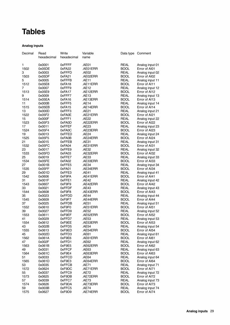
Tables
Analog inputs
Decimal Read Write Variable Data type Commenthexadecimal hexadecimal name
1 0x0001 0xFFFF .AE01 REAL Analog input 011502 0x05DE 0xFA22 .AE01ERR BOOL Error of AI013 0x0003 0xFFFD .AE02 REAL Analog input 021503 0x05DF 0xFA21 .AE02ERR BOOL Error of AI025 0x0005 0xFFFB .AE11 REAL Analog input 111512 0x05E8 0xFA18 .AE11ERR BOOL Error of AI117 0x0007 0xFFF9 .AE12 REAL Analog input 121513 0x05E9 0xFA17 .AE12ERR BOOL Error of AI129 0x0009 0xFFF7 .AE13 REAL Analog input 131514 0x05EA 0xFA16 .AE13ERR BOOL Error of AI1311 0x000B 0xFFF5 .AE14 REAL Analog input 141515 0x05EB 0xFA15 .AE14ERR BOOL Error of AI1413 0x000D 0xFFF3 .AE21 REAL Analog input 211522 0x05F2 0xFA0E .AE21ERR BOOL Error of AI2115 0x000F 0xFFF1 .AE22 REAL Analog input 221523 0x05F3 0xFA0D .AE22ERR BOOL Error of AI2217 0x0011 0xFFEF .AE23 REAL Analog input 231524 0x05F4 0xFA0C .AE23ERR BOOL Error of AI2319 0x0013 0xFFED .AE24 REAL Analog input 241525 0x05F5 0xFA0B .AE24ERR BOOL Error of AI2421 0x0015 0xFFEB .AE31 REAL Analog input 311532 0x05FC 0xFA04 .AE31ERR BOOL Error of AI3123 0x0017 0xFFE9 .AE32 REAL Analog input 321533 0x05FD 0xFA03 .AE32ERR BOOL Error of AI3225 0x0019 0xFFE7 .AE33 REAL Analog input 331534 0x05FE 0xFA02 .AE33ERR BOOL Error of AI3327 0x001B 0xFFE5 .AE34 REAL Analog input 341535 0x05FF 0xFA01 .AE34ERR BOOL Error of AI3429 0x001D 0xFFE3 .AE41 REAL Analog input 411542 0x0606 0xF9FA .AE41ERR BOOL Error of AI4131 0x001F 0xFFE1 .AE42 REAL Analog input 421543 0x0607 0xF9F9 .AE42ERR BOOL Error of AI4233 0x0021 0xFFDF .AE43 REAL Analog input 431544 0x0608 0xF9F8 .AE43ERR BOOL Error of AI4335 0x0023 0xFFDD .AE44 REAL Analog input 441545 0x0609 0xF9F7 .AE44ERR BOOL Error of AI4437 0x0025 0xFFDB .AE51 REAL Analog input 511552 0x0610 0xF9F0 .AE51ERR BOOL Error of AI5139 0x0027 0xFFD9 .AE52 REAL Analog input 521553 0x0611 0xF9EF .AE52ERR BOOL Error of AI5241 0x0029 0xFFD7 .AE53 REAL Analog input 531554 0x0612 0xF9EE .AE53ERR BOOL Error of AI5343 0x002B 0xFFD5 .AE54 REAL Analog input 541555 0x0613 0xF9ED .AE54ERR BOOL Error of AI5445 0x002D 0xFFD3 .AE61 REAL Analog input 611562 0x061A 0xF9E6 .AE61ERR BOOL Error of AI6147 0x002F 0xFFD1 .AE62 REAL Analog input 621563 0x061B 0xF9E5 .AE62ERR BOOL Error of AI6249 0x0031 0xFFCF .AE63 REAL Analog input 631564 0x061C 0xF9E4 .AE63ERR BOOL Error of AI6351 0x0033 0xFFCD .AE64 REAL Analog input 641565 0x061D 0xF9E3 .AE64ERR BOOL Error of AI6453 0x0035 0xFFCB .AE71 REAL Analog input 711572 0x0624 0xF9DC .AE71ERR BOOL Error of AI7155 0x0037 0xFFC9 .AE72 REAL Analog input 721573 0x0625 0xF9DB .AE72ERR BOOL Error of AI7257 0x0039 0xFFC7 .AE73 REAL Analog input 731574 0x0626 0xF9DA .AE73ERR BOOL Error of AI7359 0x003B 0xFFC5 .AE74 REAL Analog input 741575 0x0627 0xF9D9 .AE74ERR BOOL Error of AI74
30 Analog outputs
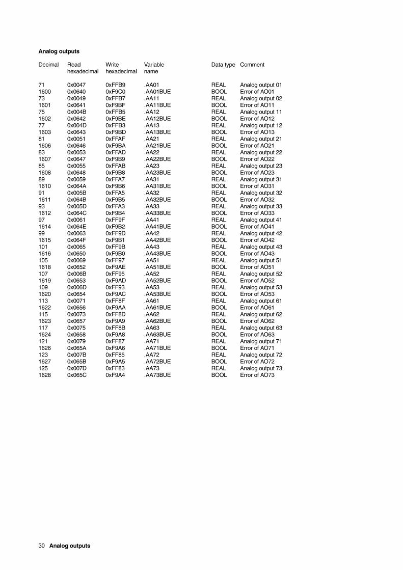
Analog outputs
Decimal Read Write Variable Data type Commenthexadecimal hexadecimal name
71 0x0047 0xFFB9 .AA01 REAL Analog output 011600 0x0640 0xF9C0 .AA01BUE BOOL Error of AO0173 0x0049 0xFFB7 .AA11 REAL Analog output 021601 0x0641 0xF9BF .AA11BUE BOOL Error of AO1175 0x004B 0xFFB5 .AA12 REAL Analog output 111602 0x0642 0xF9BE .AA12BUE BOOL Error of AO1277 0x004D 0xFFB3 .AA13 REAL Analog output 121603 0x0643 0xF9BD .AA13BUE BOOL Error of AO1381 0x0051 0xFFAF .AA21 REAL Analog output 211606 0x0646 0xF9BA .AA21BUE BOOL Error of AO2183 0x0053 0xFFAD .AA22 REAL Analog output 221607 0x0647 0xF9B9 .AA22BUE BOOL Error of AO2285 0x0055 0xFFAB .AA23 REAL Analog output 231608 0x0648 0xF9B8 .AA23BUE BOOL Error of AO2389 0x0059 0xFFA7 .AA31 REAL Analog output 311610 0x064A 0xF9B6 .AA31BUE BOOL Error of AO3191 0x005B 0xFFA5 .AA32 REAL Analog output 321611 0x064B 0xF9B5 .AA32BUE BOOL Error of AO3293 0x005D 0xFFA3 .AA33 REAL Analog output 331612 0x064C 0xF9B4 .AA33BUE BOOL Error of AO3397 0x0061 0xFF9F .AA41 REAL Analog output 411614 0x064E 0xF9B2 .AA41BUE BOOL Error of AO4199 0x0063 0xFF9D .AA42 REAL Analog output 421615 0x064F 0xF9B1 .AA42BUE BOOL Error of AO42101 0x0065 0xFF9B .AA43 REAL Analog output 431616 0x0650 0xF9B0 .AA43BUE BOOL Error of AO43105 0x0069 0xFF97 .AA51 REAL Analog output 511618 0x0652 0xF9AE .AA51BUE BOOL Error of AO51107 0x006B 0xFF95 .AA52 REAL Analog output 521619 0x0653 0xF9AD .AA52BUE BOOL Error of AO52109 0x006D 0xFF93 .AA53 REAL Analog output 531620 0x0654 0xF9AC .AA53BUE BOOL Error of AO53113 0x0071 0xFF8F .AA61 REAL Analog output 611622 0x0656 0xF9AA .AA61BUE BOOL Error of AO61115 0x0073 0xFF8D .AA62 REAL Analog output 621623 0x0657 0xF9A9 .AA62BUE BOOL Error of AO62117 0x0075 0xFF8B .AA63 REAL Analog output 631624 0x0658 0xF9A8 .AA63BUE BOOL Error of AO63121 0x0079 0xFF87 .AA71 REAL Analog output 711626 0x065A 0xF9A6 .AA71BUE BOOL Error of AO71123 0x007B 0xFF85 .AA72 REAL Analog output 721627 0x065B 0xF9A5 .AA72BUE BOOL Error of AO72125 0x007D 0xFF83 .AA73 REAL Analog output 731628 0x065C 0xF9A4 .AA73BUE BOOL Error of AO73
Digital inputs 31
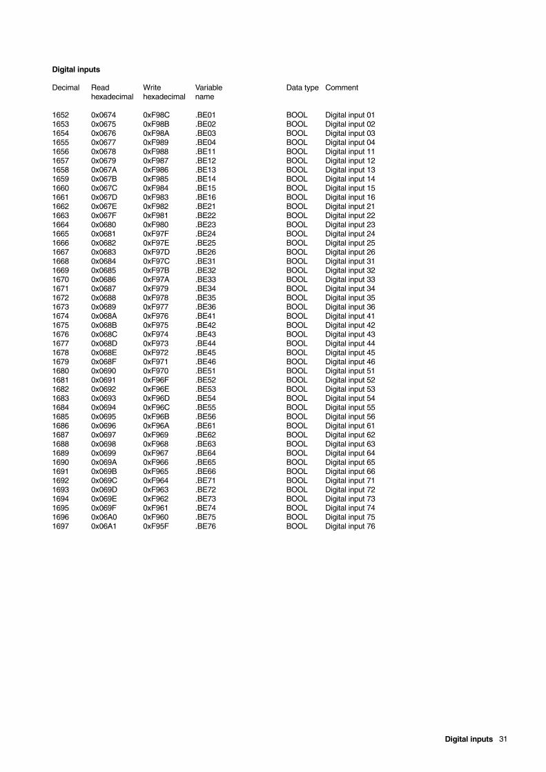
Digital inputs
Decimal Read Write Variable Data type Commenthexadecimal hexadecimal name
1652 0x0674 0xF98C .BE01 BOOL Digital input 011653 0x0675 0xF98B .BE02 BOOL Digital input 021654 0x0676 0xF98A .BE03 BOOL Digital input 031655 0x0677 0xF989 .BE04 BOOL Digital input 041656 0x0678 0xF988 .BE11 BOOL Digital input 111657 0x0679 0xF987 .BE12 BOOL Digital input 121658 0x067A 0xF986 .BE13 BOOL Digital input 131659 0x067B 0xF985 .BE14 BOOL Digital input 141660 0x067C 0xF984 .BE15 BOOL Digital input 151661 0x067D 0xF983 .BE16 BOOL Digital input 161662 0x067E 0xF982 .BE21 BOOL Digital input 211663 0x067F 0xF981 .BE22 BOOL Digital input 221664 0x0680 0xF980 .BE23 BOOL Digital input 231665 0x0681 0xF97F .BE24 BOOL Digital input 241666 0x0682 0xF97E .BE25 BOOL Digital input 251667 0x0683 0xF97D .BE26 BOOL Digital input 261668 0x0684 0xF97C .BE31 BOOL Digital input 311669 0x0685 0xF97B .BE32 BOOL Digital input 321670 0x0686 0xF97A .BE33 BOOL Digital input 331671 0x0687 0xF979 .BE34 BOOL Digital input 341672 0x0688 0xF978 .BE35 BOOL Digital input 351673 0x0689 0xF977 .BE36 BOOL Digital input 361674 0x068A 0xF976 .BE41 BOOL Digital input 411675 0x068B 0xF975 .BE42 BOOL Digital input 421676 0x068C 0xF974 .BE43 BOOL Digital input 431677 0x068D 0xF973 .BE44 BOOL Digital input 441678 0x068E 0xF972 .BE45 BOOL Digital input 451679 0x068F 0xF971 .BE46 BOOL Digital input 461680 0x0690 0xF970 .BE51 BOOL Digital input 511681 0x0691 0xF96F .BE52 BOOL Digital input 521682 0x0692 0xF96E .BE53 BOOL Digital input 531683 0x0693 0xF96D .BE54 BOOL Digital input 541684 0x0694 0xF96C .BE55 BOOL Digital input 551685 0x0695 0xF96B .BE56 BOOL Digital input 561686 0x0696 0xF96A .BE61 BOOL Digital input 611687 0x0697 0xF969 .BE62 BOOL Digital input 621688 0x0698 0xF968 .BE63 BOOL Digital input 631689 0x0699 0xF967 .BE64 BOOL Digital input 641690 0x069A 0xF966 .BE65 BOOL Digital input 651691 0x069B 0xF965 .BE66 BOOL Digital input 661692 0x069C 0xF964 .BE71 BOOL Digital input 711693 0x069D 0xF963 .BE72 BOOL Digital input 721694 0x069E 0xF962 .BE73 BOOL Digital input 731695 0x069F 0xF961 .BE74 BOOL Digital input 741696 0x06A0 0xF960 .BE75 BOOL Digital input 751697 0x06A1 0xF95F .BE76 BOOL Digital input 76
32 Digital outputs
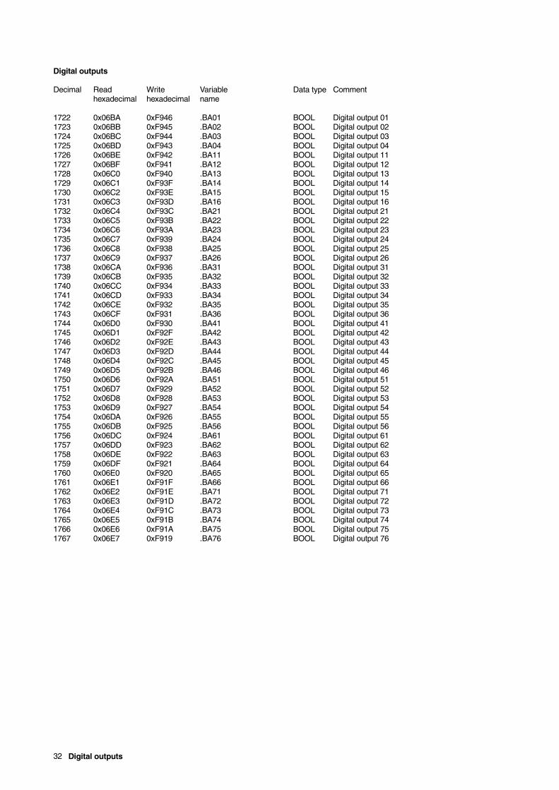
Digital outputs
Decimal Read Write Variable Data type Commenthexadecimal hexadecimal name
1722 0x06BA 0xF946 .BA01 BOOL Digital output 011723 0x06BB 0xF945 .BA02 BOOL Digital output 021724 0x06BC 0xF944 .BA03 BOOL Digital output 031725 0x06BD 0xF943 .BA04 BOOL Digital output 041726 0x06BE 0xF942 .BA11 BOOL Digital output 111727 0x06BF 0xF941 .BA12 BOOL Digital output 121728 0x06C0 0xF940 .BA13 BOOL Digital output 131729 0x06C1 0xF93F .BA14 BOOL Digital output 141730 0x06C2 0xF93E .BA15 BOOL Digital output 151731 0x06C3 0xF93D .BA16 BOOL Digital output 161732 0x06C4 0xF93C .BA21 BOOL Digital output 211733 0x06C5 0xF93B .BA22 BOOL Digital output 221734 0x06C6 0xF93A .BA23 BOOL Digital output 231735 0x06C7 0xF939 .BA24 BOOL Digital output 241736 0x06C8 0xF938 .BA25 BOOL Digital output 251737 0x06C9 0xF937 .BA26 BOOL Digital output 261738 0x06CA 0xF936 .BA31 BOOL Digital output 311739 0x06CB 0xF935 .BA32 BOOL Digital output 321740 0x06CC 0xF934 .BA33 BOOL Digital output 331741 0x06CD 0xF933 .BA34 BOOL Digital output 341742 0x06CE 0xF932 .BA35 BOOL Digital output 351743 0x06CF 0xF931 .BA36 BOOL Digital output 361744 0x06D0 0xF930 .BA41 BOOL Digital output 411745 0x06D1 0xF92F .BA42 BOOL Digital output 421746 0x06D2 0xF92E .BA43 BOOL Digital output 431747 0x06D3 0xF92D .BA44 BOOL Digital output 441748 0x06D4 0xF92C .BA45 BOOL Digital output 451749 0x06D5 0xF92B .BA46 BOOL Digital output 461750 0x06D6 0xF92A .BA51 BOOL Digital output 511751 0x06D7 0xF929 .BA52 BOOL Digital output 521752 0x06D8 0xF928 .BA53 BOOL Digital output 531753 0x06D9 0xF927 .BA54 BOOL Digital output 541754 0x06DA 0xF926 .BA55 BOOL Digital output 551755 0x06DB 0xF925 .BA56 BOOL Digital output 561756 0x06DC 0xF924 .BA61 BOOL Digital output 611757 0x06DD 0xF923 .BA62 BOOL Digital output 621758 0x06DE 0xF922 .BA63 BOOL Digital output 631759 0x06DF 0xF921 .BA64 BOOL Digital output 641760 0x06E0 0xF920 .BA65 BOOL Digital output 651761 0x06E1 0xF91F .BA66 BOOL Digital output 661762 0x06E2 0xF91E .BA71 BOOL Digital output 711763 0x06E3 0xF91D .BA72 BOOL Digital output 721764 0x06E4 0xF91C .BA73 BOOL Digital output 731765 0x06E5 0xF91B .BA74 BOOL Digital output 741766 0x06E6 0xF91A .BA75 BOOL Digital output 751767 0x06E7 0xF919 .BA76 BOOL Digital output 76
Loop 1 33
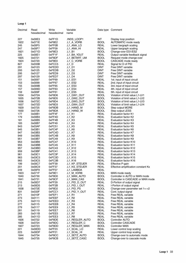
Loop 1
Decimal Read Write Variable Data type Commenthexadecimal hexadecimal name
227 0x00E3 0xFF1D .INDS_LOOP1 INT Display loop position1822 0x071E 0xF8E2 .L1_A_VORB BOOL AUTOMATIC mode ready245 0x00F5 0xFF0B .L1_ANA_LO REAL Lower bargraph scaling247 0x00F7 0xFF09 .L1_ANA_HI REAL Upper bargraph scaling1821 0x071D 0xF8E3 .L1_B1 BOOL Change-over ES1/ES2225 0x00E1 0xFF1F .L1_BA_YOUT REAL Output variable feedback signal1825 0x0721 0xF8DF .L1_BETART_UM BOOL Request mode change-over1824 0x0720 0xF8E0 .L1_C_VORB BOOL CASCADE mode ready827 0x033B 0xFCC5 .L1_D REAL Signal for D of PID291 0x0123 0xFEDD .L1_D1 DINT Free DINT variable293 0x0125 0xFEDB .L1_D2 DINT Free DINT variable295 0x0127 0xFED9 .L1_D3 DINT Free DINT variable297 0x0129 0xFED7 .L1_D4 DINT Free DINT variable151 0x0097 0xFF69 .L1_ES1 REAL 1st. input of input circuit153 0x0099 0xFF67 .L1_ES2 REAL 2nd. input of input circuit155 0x009B 0xFF65 .L1_ES3 REAL 3rd. input of input circuit157 0x009D 0xFF63 .L1_ES4 REAL 4th. input of input circuit159 0x009F 0xFF61 .L1_ES5 REAL 5th. input of input circuit1834 0x072A 0xF8D6 .L1_GW1_OUT BOOL Violation of limit value L1-LV11835 0x072B 0xF8D5 .L1_GW2_OUT BOOL Violation of limit value L1-LV21836 0x072C 0xF8D4 .L1_GW3_OUT BOOL Violation of limit value L1-LV31837 0x072D 0xF8D3 .L1_GW4_OUT BOOL Violation of limit value L1-LV41829 0x0725 0xF8DB .L1_HAND_M BOOL Step output MORE1830 0x0726 0xF8DA .L1_HAND_W BOOL Step output LESS177 0x00B1 0xFF4F .L1_K1 REAL Evaluation factor K1179 0x00B3 0xFF4D .L1_K2 REAL Evaluation factor K2181 0x00B5 0xFF4B .L1_K3 REAL Evaluation factor K3183 0x00B7 0xFF49 .L1_K4 REAL Evaluation factor K4943 0x03AF 0xFC51 .L1_K5 REAL Evaluation factor K5945 0x03B1 0xFC4F .L1_K6 REAL Evaluation factor K6947 0x03B3 0xFC4D .L1_K7 REAL Evaluation factor K7949 0x03B5 0xFC4B .L1_K8 REAL Evaluation factor K8951 0x03B7 0xFC49 .L1_K9 REAL Evaluation factor K9953 0x03B9 0xFC47 .L1_K10 REAL Evaluation factor K10955 0x03BB 0xFC45 .L1_K11 REAL Evaluation factor K11957 0x03BD 0xFC43 .L1_K12 REAL Evaluation factor K12959 0x03BF 0xFC41 .L1_K13 REAL Evaluation factor K13961 0x03C1 0xFC3F .L1_K14 REAL Evaluation factor K14963 0x03C3 0xFC3D .L1_K15 REAL Evaluation factor K15965 0x03C5 0xFC3B .L1_K16 REAL Evaluation factor K16199 0x00C7 0xFF39 .L1_KP_STEUER REAL Effective P-gain201 0x00C9 0xFF37 .L1_KS_STEUER REAL Effective amplification constant Ks249 0x00F9 0xFF07 .L1_LAMBDA REAL1823 0x071F 0xF8E1 .L1_M_VORB BOOL MAN mode ready1840 0x0730 0xF8D0 .L1_MAN_AUTO BOOL Controller in AUTO or MAN mode1841 0x0731 0xF8CF .L1_MAN_CAS BOOL Controller in CASCADE or MAN mode215 0x00D7 0xFF29 .L1_PID_D_OUT REAL D-Portion of output signal213 0x00D5 0xFF2B .L1_PID_I_OUT REAL I-Portion of output signal1838 0x072E 0xF8D2 .L1_PID_PS BOOL Change-over parameter set 1<->2831 0x033F 0xFCC1 .L1_PID_Y_OUT REAL Cont. output signal271 0x010F 0xFEF1 .L1_R1 REAL Free REAL variable273 0x0111 0xFEEF .L1_R2 REAL Free REAL variable275 0x0113 0xFEED .L1_R3 REAL Free REAL variable277 0x0115 0xFEEB .L1_R4 REAL Free REAL variable279 0x0117 0xFEE9 .L1_R5 REAL Free REAL variable281 0x0119 0xFEE7 .L1_R6 REAL Free REAL variable283 0x011B 0xFEE5 .L1_R7 REAL Free REAL variable285 0x011D 0xFEE3 .L1_R8 REAL Free REAL variable1826 0x0722 0xF8DE .L1_REGLER_AUTO BOOL Controller AUTO1828 0x0724 0xF8DC .L1_REGLER_C BOOL Controller CASCADE1827 0x0723 0xF8DD .L1_REGLER_MAN BOOL Controller MAN221 0x00DD 0xFF23 .L1_SCAL_LO REAL Lower control loop scaling223 0x00DF 0xFF21 .L1_SCAL_HI REAL Upper control loop scaling1844 0x0734 0xF8CC .L1_SETZ_AUTO BOOL Change-over to automatic mode1845 0x0735 0xF8CB .L1_SETZ_CASC BOOL Change-over to cascade mode
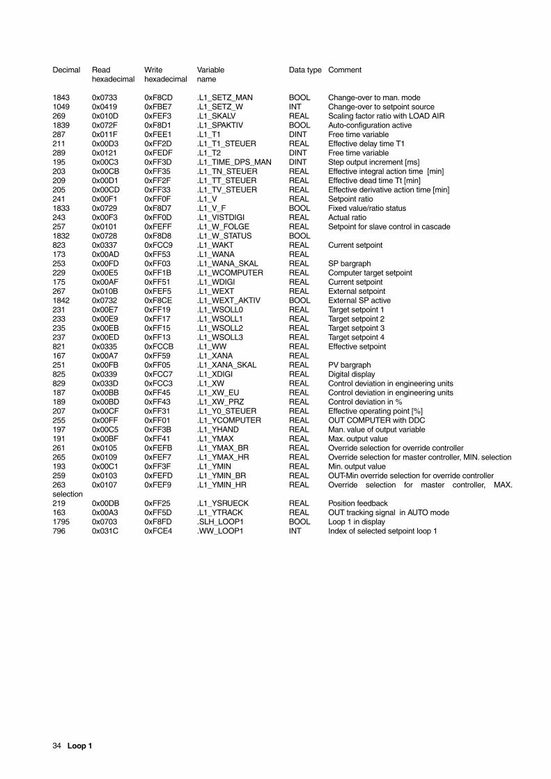
34 Loop 1
Decimal Read Write Variable Data type Commenthexadecimal hexadecimal name
1843 0x0733 0xF8CD .L1_SETZ_MAN BOOL Change-over to man. mode1049 0x0419 0xFBE7 .L1_SETZ_W INT Change-over to setpoint source269 0x010D 0xFEF3 .L1_SKALV REAL Scaling factor ratio with LOAD AIR1839 0x072F 0xF8D1 .L1_SPAKTIV BOOL Auto-configuration active287 0x011F 0xFEE1 .L1_T1 DINT Free time variable211 0x00D3 0xFF2D .L1_T1_STEUER REAL Effective delay time T1289 0x0121 0xFEDF .L1_T2 DINT Free time variable195 0x00C3 0xFF3D .L1_TIME_DPS_MAN DINT Step output increment [ms]203 0x00CB 0xFF35 .L1_TN_STEUER REAL Effective integral action time [min]209 0x00D1 0xFF2F .L1_TT_STEUER REAL Effective dead time Tt [min]205 0x00CD 0xFF33 .L1_TV_STEUER REAL Effective derivative action time [min]241 0x00F1 0xFF0F .L1_V REAL Setpoint ratio1833 0x0729 0xF8D7 .L1_V_F BOOL Fixed value/ratio status243 0x00F3 0xFF0D .L1_VISTDIGI REAL Actual ratio257 0x0101 0xFEFF .L1_W_FOLGE REAL Setpoint for slave control in cascade1832 0x0728 0xF8D8 .L1_W_STATUS BOOL823 0x0337 0xFCC9 .L1_WAKT REAL Current setpoint173 0x00AD 0xFF53 .L1_WANA REAL253 0x00FD 0xFF03 .L1_WANA_SKAL REAL SP bargraph229 0x00E5 0xFF1B .L1_WCOMPUTER REAL Computer target setpoint175 0x00AF 0xFF51 .L1_WDIGI REAL Current setpoint267 0x010B 0xFEF5 .L1_WEXT REAL External setpoint1842 0x0732 0xF8CE .L1_WEXT_AKTIV BOOL External SP active231 0x00E7 0xFF19 .L1_WSOLL0 REAL Target setpoint 1233 0x00E9 0xFF17 .L1_WSOLL1 REAL Target setpoint 2235 0x00EB 0xFF15 .L1_WSOLL2 REAL Target setpoint 3237 0x00ED 0xFF13 .L1_WSOLL3 REAL Target setpoint 4821 0x0335 0xFCCB .L1_WW REAL Effective setpoint167 0x00A7 0xFF59 .L1_XANA REAL251 0x00FB 0xFF05 .L1_XANA_SKAL REAL PV bargraph825 0x0339 0xFCC7 .L1_XDIGI REAL Digital display829 0x033D 0xFCC3 .L1_XW REAL Control deviation in engineering units187 0x00BB 0xFF45 .L1_XW_EU REAL Control deviation in engineering units189 0x00BD 0xFF43 .L1_XW_PRZ REAL Control deviation in %207 0x00CF 0xFF31 .L1_Y0_STEUER REAL Effective operating point [%]255 0x00FF 0xFF01 .L1_YCOMPUTER REAL OUT COMPUTER with DDC197 0x00C5 0xFF3B .L1_YHAND REAL Man. value of output variable191 0x00BF 0xFF41 .L1_YMAX REAL Max. output value261 0x0105 0xFEFB .L1_YMAX_BR REAL Override selection for override controller265 0x0109 0xFEF7 .L1_YMAX_HR REAL Override selection for master controller, MIN. selection193 0x00C1 0xFF3F .L1_YMIN REAL Min. output value259 0x0103 0xFEFD .L1_YMIN_BR REAL OUT-Min override selection for override controller263 0x0107 0xFEF9 .L1_YMIN_HR REAL Override selection for master controller, MAX.selection219 0x00DB 0xFF25 .L1_YSRUECK REAL Position feedback163 0x00A3 0xFF5D .L1_YTRACK REAL OUT tracking signal in AUTO mode1795 0x0703 0xF8FD .SLH_LOOP1 BOOL Loop 1 in display796 0x031C 0xFCE4 .WW_LOOP1 INT Index of selected setpoint loop 1
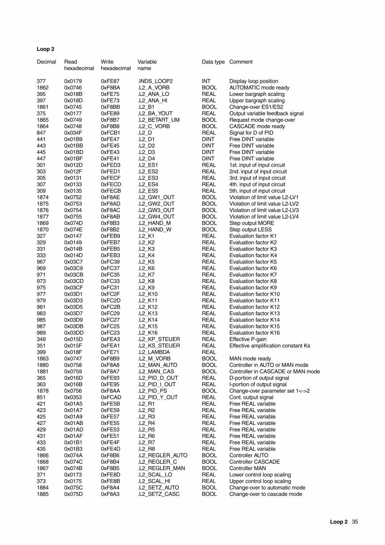
Loop 2 35
Loop 2
Decimal Read Write Variable Data type Commenthexadecimal hexadecimal name
377 0x0179 0xFE87 .INDS_LOOP2 INT Display loop position1862 0x0746 0xF8BA .L2_A_VORB BOOL AUTOMATIC mode ready395 0x018B 0xFE75 .L2_ANA_LO REAL Lower bargraph scaling397 0x018D 0xFE73 .L2_ANA_HI REAL Upper bargraph scaling1861 0x0745 0xF8BB .L2_B1 BOOL Change-over ES1/ES2375 0x0177 0xFE89 .L2_BA_YOUT REAL Output variable feedback signal1865 0x0749 0xF8B7 .L2_BETART_UM BOOL Request mode change-over1864 0x0748 0xF8B8 .L2_C_VORB BOOL CASCADE mode ready847 0x034F 0xFCB1 .L2_D REAL Signal for D of PID441 0x01B9 0xFE47 .L2_D1 DINT Free DINT variable443 0x01BB 0xFE45 .L2_D2 DINT Free DINT variable445 0x01BD 0xFE43 .L2_D3 DINT Free DINT variable447 0x01BF 0xFE41 .L2_D4 DINT Free DINT variable301 0x012D 0xFED3 .L2_ES1 REAL 1st. input of input circuit303 0x012F 0xFED1 .L2_ES2 REAL 2nd. input of input circuit305 0x0131 0xFECF .L2_ES3 REAL 3rd. input of input circuit307 0x0133 0xFECD .L2_ES4 REAL 4th. input of input circuit309 0x0135 0xFECB .L2_ES5 REAL 5th. input of input circuit1874 0x0752 0xF8AE .L2_GW1_OUT BOOL Violation of limit value L2-LV11875 0x0753 0xF8AD .L2_GW2_OUT BOOL Violation of limit value L2-LV21876 0x0754 0xF8AC .L2_GW3_OUT BOOL Violation of limit value L2-LV31877 0x0755 0xF8AB .L2_GW4_OUT BOOL Violation of limit value L2-LV41869 0x074D 0xF8B3 .L2_HAND_M BOOL Step output MORE1870 0x074E 0xF8B2 .L2_HAND_W BOOL Step output LESS327 0x0147 0xFEB9 .L2_K1 REAL Evaluation factor K1329 0x0149 0xFEB7 .L2_K2 REAL Evaluation factor K2331 0x014B 0xFEB5 .L2_K3 REAL Evaluation factor K3333 0x014D 0xFEB3 .L2_K4 REAL Evaluation factor K4967 0x03C7 0xFC39 .L2_K5 REAL Evaluation factor K5969 0x03C9 0xFC37 .L2_K6 REAL Evaluation factor K6971 0x03CB 0xFC35 .L2_K7 REAL Evaluation factor K7973 0x03CD 0xFC33 .L2_K8 REAL Evaluation factor K8975 0x03CF 0xFC31 .L2_K9 REAL Evaluation factor K9977 0x03D1 0xFC2F .L2_K10 REAL Evaluation factor K10979 0x03D3 0xFC2D .L2_K11 REAL Evaluation factor K11981 0x03D5 0xFC2B .L2_K12 REAL Evaluation factor K12983 0x03D7 0xFC29 .L2_K13 REAL Evaluation factor K13985 0x03D9 0xFC27 .L2_K14 REAL Evaluation factor K14987 0x03DB 0xFC25 .L2_K15 REAL Evaluation factor K15989 0x03DD 0xFC23 .L2_K16 REAL Evaluation factor K16349 0x015D 0xFEA3 .L2_KP_STEUER REAL Effective P-gain351 0x015F 0xFEA1 .L2_KS_STEUER REAL Effective amplification constant Ks399 0x018F 0xFE71 .L2_LAMBDA REAL1863 0x0747 0xF8B9 .L2_M_VORB BOOL MAN mode ready1880 0x0758 0xF8A8 .L2_MAN_AUTO BOOL Controller in AUTO or MAN mode1881 0x0759 0xF8A7 .L2_MAN_CAS BOOL Controller in CASCADE or MAN mode365 0x016D 0xFE93 .L2_PID_D_OUT REAL D-portion of output signal363 0x016B 0xFE95 .L2_PID_I_OUT REAL I-portion of output signal1878 0x0756 0xF8AA .L2_PID_PS BOOL Change-over parameter set 1<->2851 0x0353 0xFCAD .L2_PID_Y_OUT REAL Cont. output signal421 0x01A5 0xFE5B .L2_R1 REAL Free REAL variable423 0x01A7 0xFE59 .L2_R2 REAL Free REAL variable425 0x01A9 0xFE57 .L2_R3 REAL Free REAL variable427 0x01AB 0xFE55 .L2_R4 REAL Free REAL variable429 0x01AD 0xFE53 .L2_R5 REAL Free REAL variable431 0x01AF 0xFE51 .L2_R6 REAL Free REAL variable433 0x01B1 0xFE4F .L2_R7 REAL Free REAL variable435 0x01B3 0xFE4D .L2_R8 REAL Free REAL variable1866 0x074A 0xF8B6 .L2_REGLER_AUTO BOOL Controller AUTO1868 0x074C 0xF8B4 .L2_REGLER_C BOOL Controller CASCADE1867 0x074B 0xF8B5 .L2_REGLER_MAN BOOL Controller MAN371 0x0173 0xFE8D .L2_SCAL_LO REAL Lower control loop scaling373 0x0175 0xFE8B .L2_SCAL_HI REAL Upper control loop scaling1884 0x075C 0xF8A4 .L2_SETZ_AUTO BOOL Change-over to automatic mode1885 0x075D 0xF8A3 .L2_SETZ_CASC BOOL Change-over to cascade mode
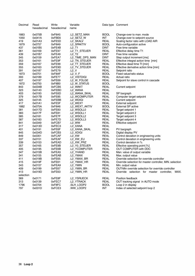
36 Loop 2
Decimal Read Write Variable Data type Commenthexadecimal hexadecimal name
1883 0x075B 0xF8A5 .L2_SETZ_MAN BOOL Change-over to man. mode1050 0x041A 0xFBE6 .L2_SETZ_W INT Change-over to setpoint source419 0x01A3 0xFE5D .L2_SKALV REAL Scaling factor ratio with LOAD AIR1879 0x0757 0xF8A9 .L2_SPAKTIV BOOL Auto-configuration active437 0x01B5 0xFE4B .L2_T1 DINT Free time variable361 0x0169 0xFE97 .L2_T1_STEUER REAL Effective delay time T1439 0x01B7 0xFE49 .L2_T2 DINT Free time variable345 0x0159 0xFEA7 .L2_TIME_DPS_MAN DINT Step output increment [ms]353 0x0161 0xFE9F .L2_TN_STEUER REAL Effective integral action time [min]359 0x0167 0xFE99 .L2_TT_STEUER REAL Effective dead time Tt [min]355 0x0163 0xFE9D .L2_TV_STEUER REAL Effective derivative action time [min]391 0x0187 0xFE79 .L2_V REAL Setpoint ratio1873 0x0751 0xF8AF .L2_V_F BOOL Fixed value/ratio status393 0x0189 0xFE77 .L2_VISTDIGI REAL Actual ratio407 0x0197 0xFE69 .L2_W_FOLGE REAL Setpoint for slave control in cascade1872 0x0750 0xF8B0 .L2_W_STATUS BOOL843 0x034B 0xFCB5 .L2_WAKT REAL Current setpoint323 0x0143 0xFEBD .L2_WANA REAL403 0x0193 0xFE6D .L2_WANA_SKAL REAL SP bargraph379 0x017B 0xFE85 .L2_WCOMPUTER REAL Computer target setpoint325 0x0145 0xFEBB .L2_WDIGI REAL Current setpoint417 0x01A1 0xFE5F .L2_WEXT REAL External setpoint1882 0x075A 0xF8A6 .L2_WEXT_AKTIV BOOL External SP active381 0x017D 0xFE83 .L2_WSOLL0 REAL Target setpoint 1383 0x017F 0xFE81 .L2_WSOLL1 REAL Target setpoint 2385 0x0181 0xFE7F .L2_WSOLL2 REAL Target setpoint 3387 0x0183 0xFE7D .L2_WSOLL3 REAL Target setpoint 4841 0x0349 0xFCB7 .L2_WW REAL Effective setpoint317 0x013D 0xFEC3 .L2_XANA REAL401 0x0191 0xFE6F .L2_XANA_SKAL REAL PV bargraph845 0x034D 0xFCB3 .L2_XDIGI REAL Digital display PV849 0x0351 0xFCAF .L2_XW REAL Control deviation in engineering units337 0x0151 0xFEAF .L2_XW_EU REAL Control deviation in engineering units339 0x0153 0xFEAD .L2_XW_PRZ REAL Control deviation in %357 0x0165 0xFE9B .L2_Y0_STEUER REAL Effective operating point [%]405 0x0195 0xFE6B .L2_YCOMPUTER REAL OUT COMPUTER with DDC347 0x015B 0xFEA5 .L2_YHAND REAL Man. value of output variable341 0x0155 0xFEAB .L2_YMAX REAL Max. output value411 0x019B 0xFE65 .L2_YMAX_BR REAL Override selection for override controller415 0x019F 0xFE61 .L2_YMAX_HR REAL Override selection for master controller, MIN. selection343 0x0157 0xFEA9 .L2_YMIN REAL Min. output value409 0x0199 0xFE67 .L2_YMIN_BR REAL OUT-Min override selection for override controller413 0x019D 0xFE63 .L2_YMIN_HR REAL Override selection for master controller, MAX.selection369 0x0171 0xFE8F .L2_YSRUECK REAL Position feedback313 0x0139 0xFEC7 .L2_YTRACK REAL OUT tracking signal in AUTO mode1796 0x0704 0xF8FC .SLH_LOOP2 BOOL Loop 2 in display797 0x031D 0xFCE3 .WW_LOOP2 INT Index of selected setpoint loop 2
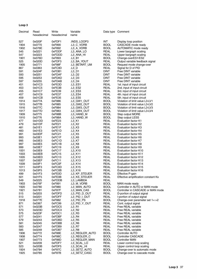
Loop 3 37
Loop 3
Decimal Read Write Variable Data type Commenthexadecimal hexadecimal name
527 0x020F 0xFDF1 .INDS_LOOP3 INT Display loop position1904 0x0770 0xF890 .L3_C_VORB BOOL CASCADE mode ready1902 0x076E 0xF892 .L3_A_VORB BOOL AUTOMATIC mode ready545 0x0221 0xFDDF .L3_ANA_LO REAL Lower bargraph scaling547 0x0223 0xFDDD .L3_ANA_HI REAL Upper bargraph scaling1901 0x076D 0xF893 .L3_B1 BOOL Change-overES1/ES2525 0x020D 0xFDF3 .L3_BA_YOUT REAL Output variable feedback signal1905 0x0771 0xF88F .L3_BETART_UM BOOL Request mode change-over867 0x0363 0xFC9D .L3_D REAL Signal for D of PID591 0x024F 0xFDB1 .L3_D1 DINT Free DINT variable593 0x0251 0xFDAF .L3_D2 DINT Free DINT variable595 0x0253 0xFDAD .L3_D3 DINT Free DINT variable597 0x0255 0xFDAB .L3_D4 DINT Free DINT variable451 0x01C3 0xFE3D .L3_ES1 REAL 1st. input of input circuit453 0x01C5 0xFE3B .L3_ES2 REAL 2nd. input of input circuit455 0x01C7 0xFE39 .L3_ES3 REAL 3rd. input of input circuit457 0x01C9 0xFE37 .L3_ES4 REAL 4th. input of input circuit459 0x01CB 0xFE35 .L3_ES5 REAL 5th. input of input circuit1914 0x077A 0xF886 .L3_GW1_OUT BOOL Violation of limit value L3-LV11915 0x077B 0xF885 .L3_GW2_OUT BOOL Violation of limit value L3-LV21916 0x077C 0xF884 .L3_GW3_OUT BOOL Violation of limit value L3-LV31917 0x077D 0xF883 .L3_GW4_OUT BOOL Violation of limit value L3-LV41909 0x0775 0xF88B .L3_HAND_M BOOL Step output MORE1910 0x0776 0xF88A .L3_HAND_W BOOL Step output LESS477 0x01DD 0xFE23 .L3_K1 REAL Evaluation factor K1479 0x01DF 0xFE21 .L3_K2 REAL Evaluation factor K2481 0x01E1 0xFE1F .L3_K3 REAL Evaluation factor K3483 0x01E3 0xFE1D .L3_K4 REAL Evaluation factor K4991 0x03DF 0xFC21 .L3_K5 REAL Evaluation factor K5993 0x03E1 0xFC1F .L3_K6 REAL Evaluation factor K6995 0x03E3 0xFC1D .L3_K7 REAL Evaluation factor K7997 0x03E5 0xFC1B .L3_K8 REAL Evaluation factor K8999 0x03E7 0xFC19 .L3_K9 REAL Evaluation factor K91001 0x03E9 0xFC17 .L3_K10 REAL Evaluation factor K101003 0x03EB 0xFC15 .L3_K11 REAL Evaluation factor K111005 0x03ED 0xFC13 .L3_K12 REAL Evaluation factor K121007 0x03EF 0xFC11 .L3_K13 REAL Evaluation factor K131009 0x03F1 0xFC0F .L3_K14 REAL Evaluation factor K141011 0x03F3 0xFC0D .L3_K15 REAL Evaluation factor K151013 0x03F5 0xFC0B .L3_K16 REAL Evaluation factor K16499 0x01F3 0xFE0D .L3_KP_STEUER REAL Effective P-gain501 0x01F5 0xFE0B .L3_KS_STEUER REAL Effective amplification constant Ks549 0x0225 0xFDDB .L3_LAMBDA REAL1903 0x076F 0xF891 .L3_M_VORB BOOL MAN mode ready1920 0x0780 0xF880 .L3_MAN_AUTO BOOL Controller in AUTO or MAN mode1921 0x0781 0xF87F .L3_MAN_CAS BOOL Controller in CASCADE or MAN mode515 0x0203 0xFDFD .L3_PID_D_OUT REAL D-portion of output signal513 0x0201 0xFDFF .L3_PID_I_OUT REAL I-portion of output signal1918 0x077E 0xF882 .L3_PID_PS BOOL Change-over parameter set 1<->2871 0x0367 0xFC99 .L3_PID_Y_OUT REAL Cont. output signal571 0x023B 0xFDC5 .L3_R1 REAL Free REAL variable573 0x023D 0xFDC3 .L3_R2 REAL Free REAL variable575 0x023F 0xFDC1 .L3_R3 REAL Free REAL variable577 0x0241 0xFDBF .L3_R4 REAL Free REAL variable579 0x0243 0xFDBD .L3_R5 REAL Free REAL variable581 0x0245 0xFDBB .L3_R6 REAL Free REAL variable583 0x0247 0xFDB9 .L3_R7 REAL Free REAL variable585 0x0249 0xFDB7 .L3_R8 REAL Free REAL variable1906 0x0772 0xF88E .L3_REGLER_AUTO BOOL Controller AUTO1908 0x0774 0xF88C .L3_REGLER_C BOOL Controller CASCADE1907 0x0773 0xF88D .L3_REGLER_MAN BOOL Controller MAN521 0x0209 0xFDF7 .L3_SCAL_LO REAL Lower control loop scaling523 0x020B 0xFDF5 .L3_SCAL_HI REAL Upper control loop scaling1924 0x0784 0xF87C .L3_SETZ_AUTO BOOL Change-over to automatic mode1925 0x0785 0xF87B .L3_SETZ_CASC BOOL Change-over to cascade mode

38 Loop 3
Decimal Read Write Variable Data type Commenthexadecimal hexadecimal name
1923 0x0783 0xF87D .L3_SETZ_MAN BOOL Change-over to man. mode1051 0x041B 0xFBE5 .L3_SETZ_W INT Change-over to setpoint source569 0x0239 0xFDC7 .L3_SKALV REAL Scaling factor ratio with LOAD AIR1919 0x077F 0xF881 .L3_SPAKTIV BOOL Auto-configuration active587 0x024B 0xFDB5 .L3_T1 DINT Free time variable511 0x01FF 0xFE01 .L3_T1_STEUER REAL Effective delay time T1589 0x024D 0xFDB3 .L3_T2 DINT Free time variable495 0x01EF 0xFE11 .L3_TIME_DPS_MAN DINT Step output increment [ms]503 0x01F7 0xFE09 .L3_TN_STEUER REAL Effective integral action time [min]509 0x01FD 0xFE03 .L3_TT_STEUER REAL Effective dead time Tt [min]505 0x01F9 0xFE07 .L3_TV_STEUER REAL Effective derivative action time [min]541 0x021D 0xFDE3 .L3_V REAL Setpoint ratio1913 0x0779 0xF887 .L3_V_F BOOL Fixed value/ratio status543 0x021F 0xFDE1 .L3_VISTDIGI REAL Actual ratio557 0x022D 0xFDD3 .L3_W_FOLGE REAL Setpoint for slave control in cascade1912 0x0778 0xF888 .L3_W_STATUS BOOL863 0x035F 0xFCA1 .L3_WAKT REAL Current setpoint473 0x01D9 0xFE27 .L3_WANA REAL553 0x0229 0xFDD7 .L3_WANA_SKAL REAL SP bargraph529 0x0211 0xFDEF .L3_WCOMPUTER REAL Computer target setpoint %475 0x01DB 0xFE25 .L3_WDIGI REAL Current setpoint567 0x0237 0xFDC9 .L3_WEXT REAL External setpoint1922 0x0782 0xF87E .L3_WEXT_AKTIV BOOL External SP active531 0x0213 0xFDED .L3_WSOLL0 REAL Target setpoint 1533 0x0215 0xFDEB .L3_WSOLL1 REAL Target setpoint 2535 0x0217 0xFDE9 .L3_WSOLL2 REAL Target setpoint 3537 0x0219 0xFDE7 .L3_WSOLL3 REAL Target setpoint 4861 0x035D 0xFCA3 .L3_WW REAL Effective setpoint467 0x01D3 0xFE2D .L3_XANA REAL551 0x0227 0xFDD9 .L3_XANA_SKAL REAL PV bargraph865 0x0361 0xFC9F .L3_XDIGI REAL Digital display PV869 0x0365 0xFC9B .L3_XW REAL Control deviation in engineering units487 0x01E7 0xFE19 .L3_XW_EU REAL Control deviation in engineering units489 0x01E9 0xFE17 .L3_XW_PRZ REAL Control deviation in %507 0x01FB 0xFE05 .L3_Y0_STEUER REAL Effective operating point [%]555 0x022B 0xFDD5 .L3_YCOMPUTER REAL OUT COMPUTER with DDC497 0x01F1 0xFE0F .L3_YHAND REAL Man. value of output variable491 0x01EB 0xFE15 .L3_YMAX REAL Max. output value561 0x0231 0xFDCF .L3_YMAX_BR REAL Override selection for override controller565 0x0235 0xFDCB .L3_YMAX_HR REAL Override selection for master controller, MIN. selection493 0x01ED 0xFE13 .L3_YMIN REAL Min. output value559 0x022F 0xFDD1 .L3_YMIN_BR REAL OUT-Min override selection for override controller563 0x0233 0xFDCD .L3_YMIN_HR REAL Override selection for master controller, MAX.selection519 0x0207 0xFDF9 .L3_YSRUECK REAL Position feedback463 0x01CF 0xFE31 .L3_YTRACK REAL OUT tracking signal in AUTO mode1797 0x0705 0xF8FB .SLH_LOOP3 BOOL Loop 3 in display798 0x031E 0xFCE2 .WW_LOOP3 INT Index of selected setpoint loop 3
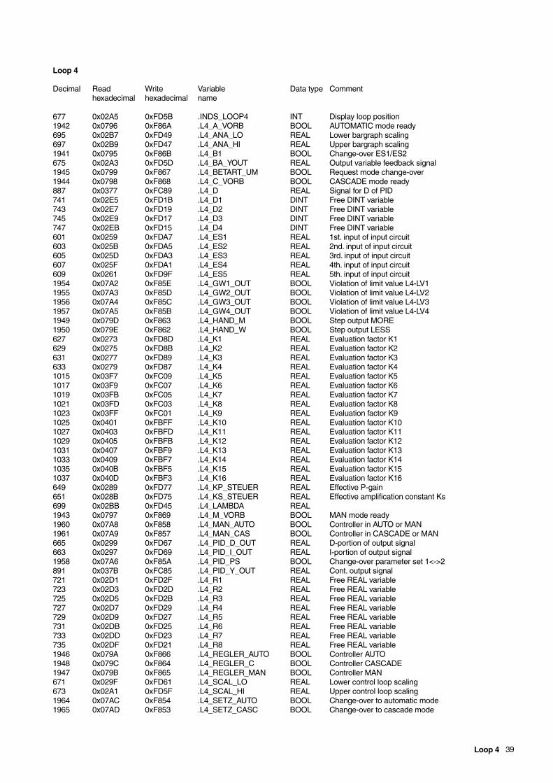
Loop 4 39
Loop 4
Decimal Read Write Variable Data type Commenthexadecimal hexadecimal name
677 0x02A5 0xFD5B .INDS_LOOP4 INT Display loop position1942 0x0796 0xF86A .L4_A_VORB BOOL AUTOMATIC mode ready695 0x02B7 0xFD49 .L4_ANA_LO REAL Lower bargraph scaling697 0x02B9 0xFD47 .L4_ANA_HI REAL Upper bargraph scaling1941 0x0795 0xF86B .L4_B1 BOOL Change-over ES1/ES2675 0x02A3 0xFD5D .L4_BA_YOUT REAL Output variable feedback signal1945 0x0799 0xF867 .L4_BETART_UM BOOL Request mode change-over1944 0x0798 0xF868 .L4_C_VORB BOOL CASCADE mode ready887 0x0377 0xFC89 .L4_D REAL Signal for D of PID741 0x02E5 0xFD1B .L4_D1 DINT Free DINT variable743 0x02E7 0xFD19 .L4_D2 DINT Free DINT variable745 0x02E9 0xFD17 .L4_D3 DINT Free DINT variable747 0x02EB 0xFD15 .L4_D4 DINT Free DINT variable601 0x0259 0xFDA7 .L4_ES1 REAL 1st. input of input circuit603 0x025B 0xFDA5 .L4_ES2 REAL 2nd. input of input circuit605 0x025D 0xFDA3 .L4_ES3 REAL 3rd. input of input circuit607 0x025F 0xFDA1 .L4_ES4 REAL 4th. input of input circuit609 0x0261 0xFD9F .L4_ES5 REAL 5th. input of input circuit1954 0x07A2 0xF85E .L4_GW1_OUT BOOL Violation of limit value L4-LV11955 0x07A3 0xF85D .L4_GW2_OUT BOOL Violation of limit value L4-LV21956 0x07A4 0xF85C .L4_GW3_OUT BOOL Violation of limit value L4-LV31957 0x07A5 0xF85B .L4_GW4_OUT BOOL Violation of limit value L4-LV41949 0x079D 0xF863 .L4_HAND_M BOOL Step output MORE1950 0x079E 0xF862 .L4_HAND_W BOOL Step output LESS627 0x0273 0xFD8D .L4_K1 REAL Evaluation factor K1629 0x0275 0xFD8B .L4_K2 REAL Evaluation factor K2631 0x0277 0xFD89 .L4_K3 REAL Evaluation factor K3633 0x0279 0xFD87 .L4_K4 REAL Evaluation factor K41015 0x03F7 0xFC09 .L4_K5 REAL Evaluation factor K51017 0x03F9 0xFC07 .L4_K6 REAL Evaluation factor K61019 0x03FB 0xFC05 .L4_K7 REAL Evaluation factor K71021 0x03FD 0xFC03 .L4_K8 REAL Evaluation factor K81023 0x03FF 0xFC01 .L4_K9 REAL Evaluation factor K91025 0x0401 0xFBFF .L4_K10 REAL Evaluation factor K101027 0x0403 0xFBFD .L4_K11 REAL Evaluation factor K111029 0x0405 0xFBFB .L4_K12 REAL Evaluation factor K121031 0x0407 0xFBF9 .L4_K13 REAL Evaluation factor K131033 0x0409 0xFBF7 .L4_K14 REAL Evaluation factor K141035 0x040B 0xFBF5 .L4_K15 REAL Evaluation factor K151037 0x040D 0xFBF3 .L4_K16 REAL Evaluation factor K16649 0x0289 0xFD77 .L4_KP_STEUER REAL Effective P-gain651 0x028B 0xFD75 .L4_KS_STEUER REAL Effective amplification constant Ks699 0x02BB 0xFD45 .L4_LAMBDA REAL1943 0x0797 0xF869 .L4_M_VORB BOOL MAN mode ready1960 0x07A8 0xF858 .L4_MAN_AUTO BOOL Controller in AUTO or MAN1961 0x07A9 0xF857 .L4_MAN_CAS BOOL Controller in CASCADE or MAN665 0x0299 0xFD67 .L4_PID_D_OUT REAL D-portion of output signal663 0x0297 0xFD69 .L4_PID_I_OUT REAL I-portion of output signal1958 0x07A6 0xF85A .L4_PID_PS BOOL Change-over parameter set 1<->2891 0x037B 0xFC85 .L4_PID_Y_OUT REAL Cont. output signal721 0x02D1 0xFD2F .L4_R1 REAL Free REAL variable723 0x02D3 0xFD2D .L4_R2 REAL Free REAL variable725 0x02D5 0xFD2B .L4_R3 REAL Free REAL variable727 0x02D7 0xFD29 .L4_R4 REAL Free REAL variable729 0x02D9 0xFD27 .L4_R5 REAL Free REAL variable731 0x02DB 0xFD25 .L4_R6 REAL Free REAL variable733 0x02DD 0xFD23 .L4_R7 REAL Free REAL variable735 0x02DF 0xFD21 .L4_R8 REAL Free REAL variable1946 0x079A 0xF866 .L4_REGLER_AUTO BOOL Controller AUTO1948 0x079C 0xF864 .L4_REGLER_C BOOL Controller CASCADE1947 0x079B 0xF865 .L4_REGLER_MAN BOOL Controller MAN671 0x029F 0xFD61 .L4_SCAL_LO REAL Lower control loop scaling673 0x02A1 0xFD5F .L4_SCAL_HI REAL Upper control loop scaling1964 0x07AC 0xF854 .L4_SETZ_AUTO BOOL Change-over to automatic mode1965 0x07AD 0xF853 .L4_SETZ_CASC BOOL Change-over to cascade mode

40 Loop 4
Decimal Read Write Variable Data type Commenthexadecimal hexadecimal name
1963 0x07AB 0xF855 .L4_SETZ_MAN BOOL Change-over to man. mode1052 0x041C 0xFBE4 .L4_SETZ_W INT Change-over to setpoint source719 0x02CF 0xFD31 .L4_SKALV REAL Scaling factor ratio with LOAD AIR1959 0x07A7 0xF859 .L4_SPAKTIV BOOL Auto-configuration active737 0x02E1 0xFD1F .L4_T1 DINT Free time variable661 0x0295 0xFD6B .L4_T1_STEUER REAL Effective delay time T1739 0x02E3 0xFD1D .L4_T2 DINT Free time variable645 0x0285 0xFD7B .L4_TIME_DPS_MAN DINT Step output increment [ms]653 0x028D 0xFD73 .L4_TN_STEUER REAL Effective integral action time [min]659 0x0293 0xFD6D .L4_TT_STEUER REAL Effective dead time Tt [min]655 0x028F 0xFD71 .L4_TV_STEUER REAL Effective derivative action time [min]691 0x02B3 0xFD4D .L4_V REAL Setpoint ratio1953 0x07A1 0xF85F .L4_V_F BOOL Fixed value/ratio status693 0x02B5 0xFD4B .L4_VISTDIGI REAL Actual ratio707 0x02C3 0xFD3D .L4_W_FOLGE REAL Setpoint for slave control in cascade1952 0x07A0 0xF860 .L4_W_STATUS BOOL883 0x0373 0xFC8D .L4_WAKT REAL Current setpoint623 0x026F 0xFD91 .L4_WANA REAL703 0x02BF 0xFD41 .L4_WANA_SKAL REAL SP bargraph679 0x02A7 0xFD59 .L4_WCOMPUTER REAL Computer target setpoint625 0x0271 0xFD8F .L4_WDIGI REAL Current setpoint717 0x02CD 0xFD33 .L4_WEXT REAL External setpoint1962 0x07AA 0xF856 .L4_WEXT_AKTIV BOOL External SP active681 0x02A9 0xFD57 .L4_WSOLL0 REAL Target setpoint 1683 0x02AB 0xFD55 .L4_WSOLL1 REAL Target setpoint 2685 0x02AD 0xFD53 .L4_WSOLL2 REAL Target setpoint 3687 0x02AF 0xFD51 .L4_WSOLL3 REAL Target setpoint 4881 0x0371 0xFC8F .L4_WW REAL Effective setpoint617 0x0269 0xFD97 .L4_XANA REAL701 0x02BD 0xFD43 .L4_XANA_SKAL REAL PV bargraph885 0x0375 0xFC8B .L4_XDIGI REAL Digital display PV889 0x0379 0xFC87 .L4_XW REAL Control deviation in engineering units637 0x027D 0xFD83 .L4_XW_EU REAL Control deviation in engineering units639 0x027F 0xFD81 .L4_XW_PRZ REAL Control deviation in %657 0x0291 0xFD6F .L4_Y0_STEUER REAL Effective operating point [%]705 0x02C1 0xFD3F .L4_YCOMPUTER REAL OUT COMPUTER with DDC647 0x0287 0xFD79 .L4_YHAND REAL Man. value of output variable641 0x0281 0xFD7F .L4_YMAX REAL Max. output value711 0x02C7 0xFD39 .L4_YMAX_BR REAL Override selection for override controller715 0x02CB 0xFD35 .L4_YMAX_HR REAL Override selection for master controller, MIN. selection643 0x0283 0xFD7D .L4_YMIN REAL Min. output value709 0x02C5 0xFD3B .L4_YMIN_BR REAL OUT-Min override selection for override controller713 0x02C9 0xFD37 .L4_YMIN_HR REAL Override selection for master controller, MAX.selection669 0x029D 0xFD63 .L4_YSRUECK REAL Position feedback613 0x0265 0xFD9B .L4_YTRACK REAL OUT tracking signal in AUTO mode1798 0x0706 0xF8FA .SLH_LOOP4 BOOL Loop 4 in display799 0x031F 0xFCE1 .WW_LOOP4 INT Index of selected setpoint loop 4
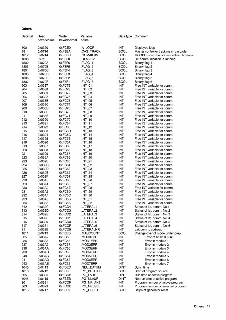
Others 41
Others
Decimal Read Write Variable Data type Commenthexadecimal hexadecimal name
800 0x0320 0xFCE0 .A_LOOP INT Displayed loop1814 0x0716 0xF8EA .CAS_TRACK BOOL Master controller tracking in cascade1812 0x0714 0xF8EC .COMAKTIV BOOL MODBUS-communication without time-out1808 0x710 0xF8F0 .DPAKTIV BOOL DP communication is running1802 0x070A 0xF8F6 .FLAG_1 BOOL Binary flag 11803 0x070B 0xF8F5 .FLAG_2 BOOL Binary flag 21804 0x070C 0xF8F4 .FLAG_3 BOOL Binary flag 31805 0x070D 0xF8F3 .FLAG_4 BOOL Binary flag 41806 0x070E 0xF8F2 .FLAG_5 BOOL Binary flag 51807 0x070F 0xF8F1 .FLAG_6 BOOL Binary flag 6903 0x0387 0xFC79 .INT_01 INT Free INT variable for comm.904 0x0388 0xFC78 .INT_02 INT Free INT variable for comm.905 0x0389 0xFC77 .INT_03 INT Free INT variable for comm.906 0x038A 0xFC76 .INT_04 INT Free INT variable for comm.907 0x038B 0xFC75 .INT_05 INT Free INT variable for comm.908 0x038C 0xFC74 .INT_06 INT Free INT variable for comm.909 0x038D 0xFC73 .INT_07 INT Free INT variable for comm.910 0x038E 0xFC72 .INT_08 INT Free INT variable for comm.911 0x038F 0xFC71 .INT_09 INT Free INT variable for comm.912 0x0390 0xFC70 .INT_10 INT Free INT variable for comm.913 0x0391 0xFC6F .INT_11 INT Free INT variable for comm.914 0x0392 0xFC6E .INT_12 INT Free INT variable for comm.915 0x0393 0xFC6D .INT_13 INT Free INT variable for comm.916 0x0394 0xFC6C .INT_14 INT Free INT variable for comm.917 0x0395 0xFC6B .INT_15 INT Free INT variable for comm.918 0x0396 0xFC6A .INT_16 INT Free INT variable for comm.919 0x0397 0xFC69 .INT_17 INT Free INT variable for comm.920 0x0398 0xFC68 .INT_18 INT Free INT variable for comm.921 0x0399 0xFC67 .INT_19 INT Free INT variable for comm.922 0x039A 0xFC66 .INT_20 INT Free INT variable for comm.923 0x039B 0xFC65 .INT_21 INT Free INT variable for comm.924 0x039C 0xFC64 .INT_22 INT Free INT variable for comm.925 0x039D 0xFC63 .INT_23 INT Free INT variable for comm.926 0x039E 0xFC62 .INT_24 INT Free INT variable for comm.927 0x039F 0xFC61 .INT_25 INT Free INT variable for comm.928 0x03A0 0xFC60 .INT_26 INT Free INT variable for comm.929 0x03A1 0xFC5F .INT_27 INT Free INT variable for comm.930 0x03A2 0xFC5E .INT_28 INT Free INT variable for comm.931 0x03A3 0xFC5D .INT_29 INT Free INT variable for comm.932 0x03A4 0xFC5C .INT_30 INT Free INT variable for comm.933 0x03A5 0xFC5B .INT_31 INT Free INT variable for comm.934 0x03A6 0xFC5A .INT_32 INT Free INT variable for comm.812 0x032C 0xFCD4 .LATERAL1 INT Status of lat. comm. No.1813 0x032D 0xFCD3 .LATERAL2 INT Status of lat. comm. No. 2814 0x032E 0xFCD2 .LATERAL3 INT Status of lat. comm. No. 3815 0x032F 0xFCD1 .LATERAL4 INT Status of lat. comm. No. 4816 0x0330 0xFCD0 .LATERAL5 INT Status of lat. comm. No. 5817 0x0331 0xFCCF .LATERAL6 INT Status of lat. comm. No. 6811 0x032B 0xFCD5 .LATERALNR INT Lat. comm. address1811 0x0713 0xF8ED .MACCOUNT BOOL Change-over of mode under prep.935 0x03A7 0xFC59 .MOD0ERR INT Error of basic IO unit936 0x03A8 0xFC58 .MOD1ERR INT Error in module 1937 0x03A9 0xFC57 .MOD2ERR INT Error in module 2938 0x03AA 0xFC56 .MOD3ERR INT Error in module 3939 0x03AB 0xFC55 .MOD4ERR INT Error in module 4940 0x03AC 0xFC54 .MOD5ERR INT Error in module 5941 0x03AD 0xFC53 .MOD6ERR INT Error in module 6942 0x03AE 0xFC52 .MOD7ERR INT Error in module 71043 0x0413 0xFBED .NEU_DATUM DINT Sync. time1810 0x0712 0xF8EE .PG_BETRIEB BOOL Start of program source805 0x0325 0xFCDB .PG_LAUF DINT Run time of active program1045 0x0415 0xFBEB .PG_NLAUF DINT Net run time of active program801 0x0321 0xFCDF .PG_NR_AKT INT Program number of active program803 0x0323 0xFCDD .PG_NR_SEL INT Program number of selected program1815 0x0717 0xF8E9 .PG_RESET BOOL Setpoint generator reset
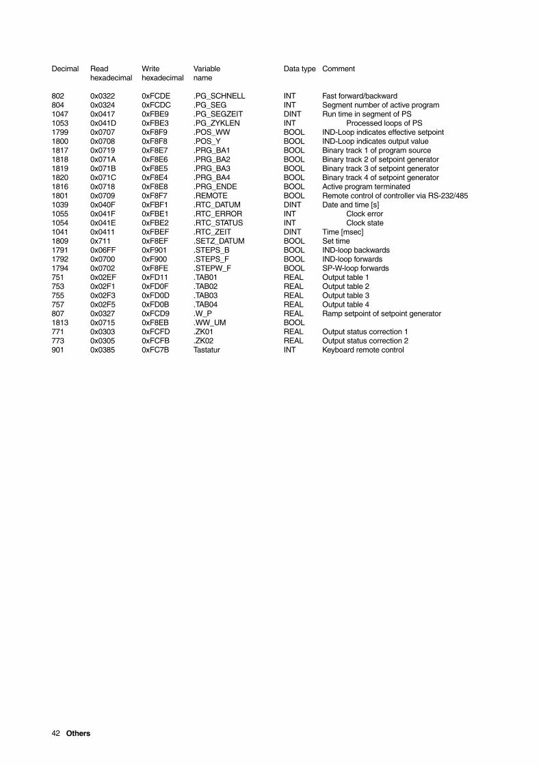
42 Others
Decimal Read Write Variable Data type Commenthexadecimal hexadecimal name
802 0x0322 0xFCDE .PG_SCHNELL INT Fast forward/backward804 0x0324 0xFCDC .PG_SEG INT Segment number of active program1047 0x0417 0xFBE9 .PG_SEGZEIT DINT Run time in segment of PS1053 0x041D 0xFBE3 .PG_ZYKLEN INT Processed loops of PS1799 0x0707 0xF8F9 .POS_WW BOOL IND-Loop indicates effective setpoint1800 0x0708 0xF8F8 .POS_Y BOOL IND-Loop indicates output value1817 0x0719 0xF8E7 .PRG_BA1 BOOL Binary track 1 of program source1818 0x071A 0xF8E6 .PRG_BA2 BOOL Binary track 2 of setpoint generator1819 0x071B 0xF8E5 .PRG_BA3 BOOL Binary track 3 of setpoint generator1820 0x071C 0xF8E4 .PRG_BA4 BOOL Binary track 4 of setpoint generator1816 0x0718 0xF8E8 .PRG_ENDE BOOL Active program terminated1801 0x0709 0xF8F7 .REMOTE BOOL Remote control of controller via RS-232/4851039 0x040F 0xFBF1 .RTC_DATUM DINT Date and time [s]1055 0x041F 0xFBE1 .RTC_ERROR INT Clock error1054 0x041E 0xFBE2 .RTC_STATUS INT Clock state1041 0x0411 0xFBEF .RTC_ZEIT DINT Time [msec]1809 0x711 0xF8EF .SETZ_DATUM BOOL Set time1791 0x06FF 0xF901 .STEPS_B BOOL IND-loop backwards1792 0x0700 0xF900 .STEPS_F BOOL IND-loop forwards1794 0x0702 0xF8FE .STEPW_F BOOL SP-W-loop forwards751 0x02EF 0xFD11 .TAB01 REAL Output table 1753 0x02F1 0xFD0F .TAB02 REAL Output table 2755 0x02F3 0xFD0D .TAB03 REAL Output table 3757 0x02F5 0xFD0B .TAB04 REAL Output table 4807 0x0327 0xFCD9 .W_P REAL Ramp setpoint of setpoint generator1813 0x0715 0xF8EB .WW_UM BOOL771 0x0303 0xFCFD .ZK01 REAL Output status correction 1773 0x0305 0xFCFB .ZK02 REAL Output status correction 2901 0x0385 0xFC7B Tastatur INT Keyboard remote control

Packaging for ... 43
Packaging for Transport or for Return to the Manufacturer-If the original packaging material is no longer available, wrap themodule in a padded plastic film or corrugated paper board. Put thewrapped device in a box laid out with a damping material likefoamed plastics. The thickness of the damping material should bein accordance with the device weight and the type oftransportation.-- Label the box with a "handle with care" sticker.
For overseas shipping always add a desiccant bag (e.g. filled withsilica gel) and then weld the device in a 0.2 mm polyethylene foil.Adapt the amount of desiccant to the packing- volume and theapproximate transportation time (at least 3 months). Additionallyline the box with a layer of union paper.-

ABB Automation Products GmbHHoeseler Platz 242579 HeiligenhausDEUTSCHLANDPhone +49205612-5181Fax +492056 12-50 81http://www.abb.com
Subject to technical changes.Printed in the Fed. R. of Germany
42/62-50050 EN Rev. 02Date of issue 08.02
Subject to technical changes.
This technical documentation is protected by copyright. Translating, photocopying and diseminating it in any form whatsoever - eveneditings or excerpts thereof - especially as reprint, photomechanical or electronic reproduction or storage on data processing systems ornetworks is not allowed without the permission of the copyright owner and non-compliance will lead to both civil and criminal prosecution.