Prototyping ME110 Spring 2003. Planning Concept Development Concept Development System-Level Design...
58
Prototyping ME110 Spring 2003
-
date post
19-Dec-2015 -
Category
Documents
-
view
220 -
download
0
Transcript of Prototyping ME110 Spring 2003. Planning Concept Development Concept Development System-Level Design...

Prototyping
ME110
Spring 2003

PlanningPlanning ConceptDevelopment
ConceptDevelopment
System-LevelDesign
System-LevelDesign
DetailDesign
DetailDesign
Testing andRefinement
Testing andRefinement
ProductionRamp-Up
ProductionRamp-Up
Prototyping is done throughout the development process.
Product Development Process

RiskAnalysis Prototype 1
Prototype 3Prototype
2
OperationalPrototype
RiskAnalysis
RiskAnalysis
RiskAnalysis
Simulations, models, benchmarks
Determine objectives,alternatives, constraints
Plan next phases Develop, verify
Evaluate alternatives,identify, resolve risks
ConceptRequirements
Plan
DevelopmentPlan
Integrationand test plan
RequirementsValidation
Design Validationand Verification
Final Code Implementationand Test
Adapted from B. Boehm
Spiral Model of Product Development

Four Uses of Prototypes
Learning– answering questions about performance or feasibility– e.g., proof-of-concept model
Communication– demonstration of product for feedback: visual, tactile, functional– e.g., 3D physical models of style or function
Integration– combination of sub-systems into system model– e.g., alpha or beta test models
Milestones– goal for development team’s schedule– e.g., first testable hardware

Types of Prototypes
ComprehensiveFocused
Physical
Analytical
finalproduct
betaprototype
alphaprototype
ballsupport
prototype
simulationof trackball
circuits
equationsmodeling ball
supports
trackball mechanismlinked to circuit
simulation
notgenerallyfeasible

Physical vs. Analytical Prototypes
Physical Prototypes Tangible approximation of the
product. May exhibit unmodeled
behavior. Some behavior may be an
artifact of the approximation. Often best for communication.
Analytical Prototypes Mathematical model of the
product. Can only exhibit behavior
arising from explicitly modeled phenomena. (However, behavior is not always anticipated.
Some behavior may be an artifact of the analytical method.
Often allow more experimental freedom than physical models.

Focused vs. Comprehensive Prototypes
Focused Prototypes Implement one or a few
attributes of the product. Answer specific
questions about the product design.
Generally several are required.
Comprehensive Prototypes
Implement many or all attributes of the product.
Offer opportunities for rigorous testing.
Often best for milestones and integration.
Concept Prototypes Can Be Communicated in Multiple Ways:
Verbal descriptions Sketches Photos and renderings Storyboards – a series of images that communicates a
temporal sequence of actions involving the product Videos – dynamic storyboards Simulation Interactive multimedia – combines the visual richness of video
with the interactivity of simulation Physical appearance models Working prototypes

Traditional Prototyping Methods
Model from clay Carve from wood or styrofoam Bend wire meshing CNC machining (pastic or aluminum) Rubber molding + urethane casting
Materials: wood, foam, plastics, etc. Model making requires special skills.


Fidelity in Prototyping
Fidelity refers to the level of detail High fidelity?
– prototypes look like the final product Low fidelity?
– artists renditions with many details missing
Profs. Jen Mankoff and James Landay, CS

Low-fi Storyboards for User Interface Interactions
Where do storyboards come from?– film & animation
Give you a “script” of important events– leave out the details – concentrate on the important interactions
Profs. Jen Mankoff and James Landay, CS

Why Use Low-fi Prototypes?
Traditional methods take too long– sketches -> prototype -> evaluate -> iterate
Can simulate the prototype– sketches -> evaluate -> iterate– sketches act as prototypes
designer “plays computer” other design team members observe & record
Kindergarten implementation skills– allows non-programmers to participate
Profs. Jen Mankoff and James Landay, CS

Hi-fi Prototypes Warp
Perceptions of the customer/reviewer?– formal representation indicates “finished” nature
comments on color, fonts, and alignment
Time?– encourage precision
specifying details takes more time
Creativity?– lose track of the big picture
Profs. Jen Mankoff and James Landay, CS

Wizard of Oz Technique (?)
Faking the interaction. Comes from?– from the film “The Wizard of OZ”
“the man behind the curtain”
Long tradition in computer industry– prototype of a PC w/ a VAX behind the curtain
Much more important for hard to implement features– Speech & handwriting recognition
Profs. Jen Mankoff and James Landay, CS

The Basic Materials for Low-fi Prototyping of Visual UIs
Large, heavy, white paper (11 x 17) 5x8 in. index cards Tape, stick glue, correction tape Pens & markers (many colors & sizes) Overhead transparencies Scissors, X-acto knives, etc.
Profs. Jen Mankoff and James Landay, CS

Constructing the Model
Set a deadline– don’t think too long - build it!
Draw a window frame on large paper Put different screen regions on cards
– anything that moves, changes, appears/disappears Ready response for any customer action
– e.g., have those pull-down menus already made Use photocopier to make many versions
Profs. Jen Mankoff and James Landay, CS


ESP
Low-fi Prototypes
Profs. Jen Mankoff and James Landay, CS

High Performance Companies:
Not only verify that the final product meets customer expectations,
But involve potential customers directly in various stages of development and encourage partnerships
Which allows faster cycling for customer feedback
And creates better-suited products

Virtual Prototyping
3D CAD models enable many kinds of analysis:– Fit and assembly– Manufacturability– Form and style– Kinematics– Finite element analysis (stress, thermal)– Crash testing– more every year...
Simulation, Optimization

Boeing 777 Testing
Rapid design-build philosophy 100% digital CAD & 3D modeling Part Interference Brakes Test Minimum rotor thickness Maximum takeoff weight Maximum runway speed Will the brakes ignite? Wing Test Maximum loading When will it break? Where will it break?


CATIA CAD Modeling & Analysis
100% digital design on the Boeing 777
Used to discover tolerance error early in the design cycle
Greatly reduced the number of design changes and costs

Simulations of all Operations

Physical Rapid Prototyping Methods
Build parts in layers based on CAD model.– Conceptually, like stacking many tailored pieces of cardboard on
top of one another.– SLA=Stereolithography Apparatus (Cory Hall, Prof. Carlo Sequin)– Solid Imaging (Cory Hall, Prof. Carlo Sequin)– SLS=Selective Laser Sintering– FDM= Fused Deposition Modeling (Tour - Etcheverry Hall, Prof.
Paul Wright)– Color/Mono 3D Printing (e.g., Z-Corp) (Tour - Etcheverry Hall)
Solid Injection Molding Others every year...

Selective Laser Sintering
Thermoplastic powder is spread by a roller over the surface of a build cylinder.
The piston in the cylinder moves down one object layer thickness to accommodate the new layer of powder.
A laser beam is traced over the surface of this tightly compacted powder to selectively melt and bond it to form a layer of the object.
Excess powder is brushed away and final manual finishing may be carried out.

SLA=Stereolithography Apparatus
Builds plastic parts or objects a layer at a time by tracing a laser beam on the surface of a vat of a photosensitive liquid polymer.
Photopolymer quickly solidifies wherever the laser beam strikes the surface of the liquid.
Repeated by lowering a small distance into the vat and a second layer is traced right on top of the first.
Self-adhesive property of the material causes the layers to bond to one another and eventually form a complete, three-dimensional object after many such layers are formed.

Stereolithography (SLA)
SLA Machine by 3D Systems
Maximum build envelope: 350 x 350 x 400 mm in XYZ
Vertical resolution: 0.00177 mm Position repeatability: ±0.005 mm Maximum part weight: 56.8 kg
Prof. Carlo Séquin, CS

Stereolithography Evaluation
Can do intricate shapes with small holes High precision Moderately Fast Photopolymer is expensive ($700/gallon) Laser is expensive ($10’000),
lasts only about 2000 hrs.
Prof. Carlo Séquin, CS

Model Prototype Mold Part
Injection-Molded Housing for ST TouchChip
Prof. Carlo Séquin, CS
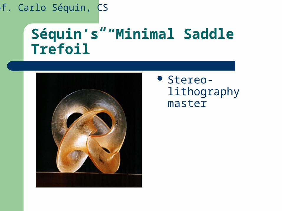
Séquin’s “Minimal Saddle Trefoil”
Stereo-lithography master
Prof. Carlo Séquin, CS

Séquin’s “Minimal Saddle Trefoil”
bronze cast, gold plated
Prof. Carlo Séquin, CS

Solid Imaging: Thermojet Printing
Technology: Multi-Jet Modeling (MJM)
Uses plastic and wax. Need to build a support
structures where there are overhangs / bridges that must be removed manually.
Resolution (x,y,z): 300 x 400 x 600 DPI
Maximum Model Size: 10 x 7.5 x 8 in (13 lb)
Prof. Carlo Séquin, CS

Solid Imaging Example
That’s how partsemerge from theThermojet printer
After partial removalof the supportingscaffolding
Prof. Carlo Séquin, CS

Prof. Carlo Séquin, CS
9-Story Intertwined Double Toroid
Bronze investment casting from wax original
made on 3D Systems’“Thermojet”

Prof. Carlo Séquin, CS
Solid Imaging Evaluation
An Informal Evaluation Fast Inexpensive Reliable, robust Good for investment casting Support removal takes some care
(refrigerate model beforehand) Thermojet 88 parts are fragile

3D Printing: Some Key Players
Soligen: http://www.zcorp.com/Metal and ceramic powdersfor operational prototypes.
Z Corporation: http://www.zcorp.com/Plaster and starch powders for visualization models.
– Needs no supports that must be removed!
– Uniform bed of powder acts as support.
– This powder gets selectively (locally) glued (or fused) together to create the solid portions of the desired part.
Prof. Carlo Séquin, CS

3D Printing: Z Corporation
The Z402 3D Printer– Speed: 1-2 vertical inches
per hour– Build Volume: 8" x 10" x
8" – Thickness: 3 to 10 mils,
selectable
Prof. Carlo Séquin, CS

Three Dimensional Printing
A layer of powder object material is deposited at the top of a fabrication chamber.
Roller then distributes and compresses the powder at the top of the fabrication chamber.
Multi-channel jetting head subsequently deposits a liquid adhesive in a two dimensional pattern onto the layer of the powder which becomes bonded in the areas where the adhesive is deposited, to form a layer of the object.

3D Printing: Z Corporation
Prof. Carlo Séquin, CS

3D Printing: Z Corporation
Digging out
Prof. Carlo Séquin, CS

Optional Curing: 30 min. @ 200ºF
Keep some powder in place
<-- Tray for transport
Prof. Carlo Séquin, CS

3D Printing: Z Corporation
Cleaning up in the de-powdering station
Prof. Carlo Séquin, CS

3D Printing: Z Corporation
The finished part Zcorp,
6” diam.,
6hrs.
Prof. Carlo Séquin, CS

120 Cell -- Close-up
Prof. Carlo Séquin, CS

3D Color Printing: Z Corporation
Use compressed air to blow out central hollow space.
Prof. Carlo Séquin, CS
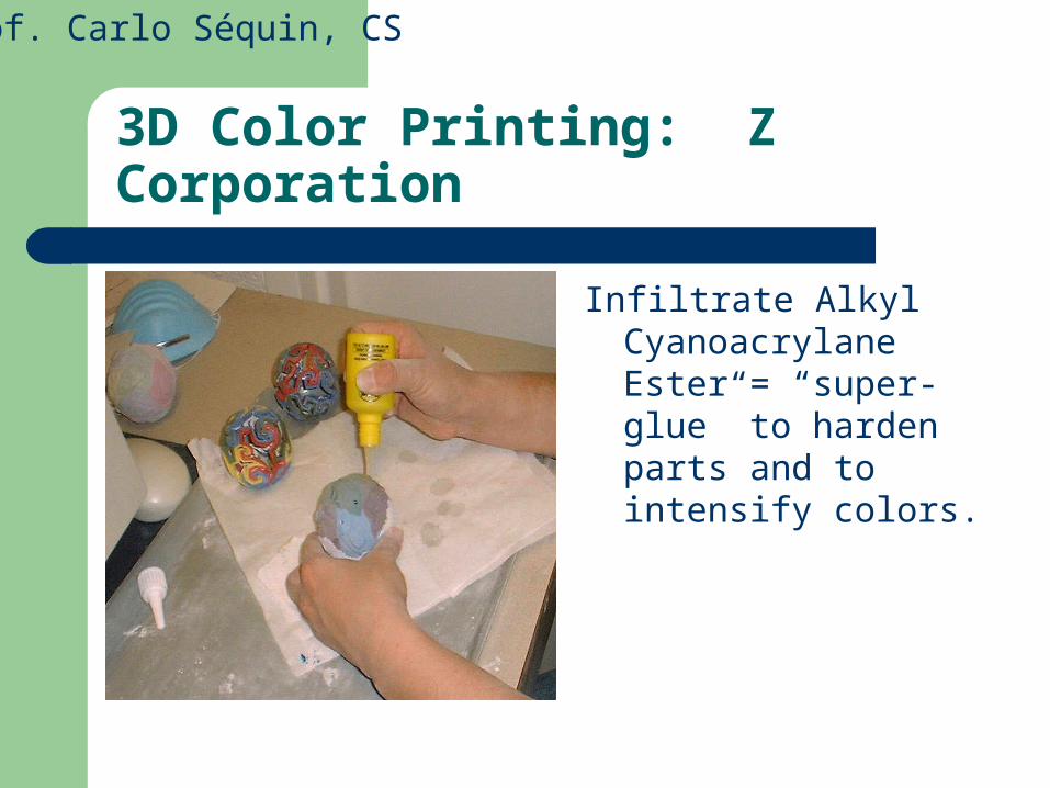
3D Color Printing: Z Corporation
Infiltrate Alkyl Cyanoacrylane Ester = “super-glue” to harden parts and to intensify colors.
Prof. Carlo Séquin, CS

What Can Go Wrong ?
Blocked glue lines Crumbling parts
Prof. Carlo Séquin, CS

3D Printing (Z Corporation) Evaluation
Fast ! Running expenses: moderate,
(but overpriced powder) Color print head and tubes need
some care in maintenance. Somewhat messy cleanup ! Lot’s of dust everywhere ...
Fused Deposition Modeling
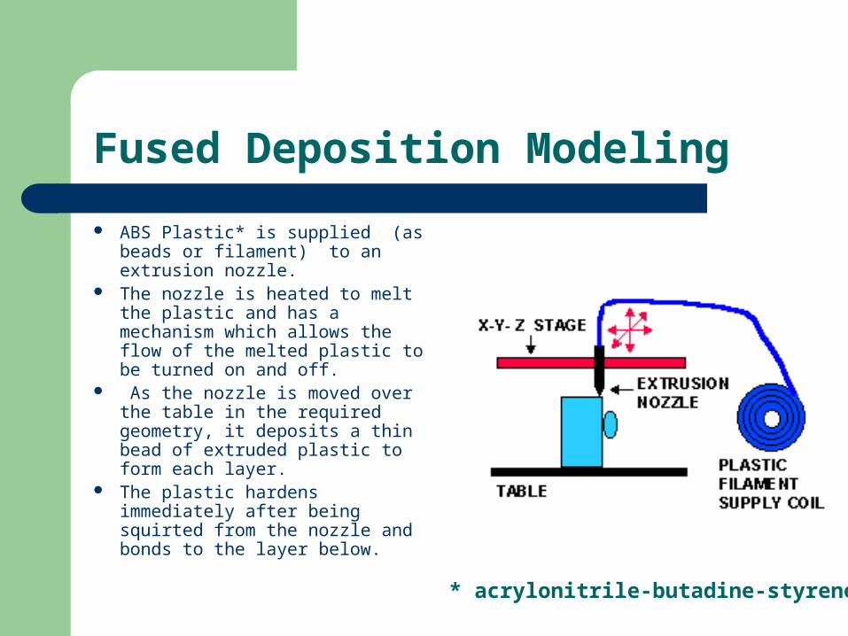
ABS Plastic* is supplied (as beads or filament) to an extrusion nozzle.
The nozzle is heated to melt the plastic and has a mechanism which allows the flow of the melted plastic to be turned on and off.
As the nozzle is moved over the table in the required geometry, it deposits a thin bead of extruded plastic to form each layer.
The plastic hardens immediately after being squirted from the nozzle and bonds to the layer below.
* acrylonitrile-butadine-styrene

Fused Deposition Modeling
Stratasys: http://www.stratasys.com/
Prof. Carlo Séquin, CS

Looking into the FDM Machine
Prof. Carlo Séquin, CS

Layered Fabrication of Klein Bottle
Support material
Prof. Carlo Séquin, CS

Klein Bottle Skeleton (FDM)
Prof. Carlo Séquin, CS

Prof. Carlo Séquin, CS
Fused Deposition Modeling (FDM) Evaluation
Easy to use Rugged and robust Could have this in your office Good transparent software (Quickslice)
with multiple entry points: STL, SSL, SML Inexpensive to operate Slow Think about support removal !

What Can Go Wrong ?
Black blobs
Toppled supports
Prof. Carlo Séquin, CS