Variable Frequency Drive Wireless Interface Prototype Final Report
i
PROTOTYPE OF POWER LINE INTERFACE SOCKET USING EMBEDDED
CONTROLLER FOR DATA ACQUISITION AND CONTROL.
LAI CHING HUAT
This Report Is Submitted In Partial Fulfillment of Requirements for the Bachelor Degree
of Electronic Engineering (Computer Engineering)
Faculty of Electronic and Computer Engineering
Universiti Teknikal Malaysia Melaka
June 2012
ii
UNIVERSTI TEKNIKAL MALAYSIA MELAKA FAKULTI KEJURUTERAAN ELEKTRONIK DAN KEJURUTERAAN KOMPUTER
BORANG PENGESAHAN STATUS LAPORAN
PROJEK SARJANA MUDA II
Tajuk Projek :
PROTOTYPE OF POWER LINE INTERFACE SOCKET USING EMBEDDED CONTROLLER FOR DATA ACQUISITION AND CONTROL.
Sesi Pengajian : 1 1 / 1 2
Saya LAI CHING HUAT mengaku membenarkan Laporan Projek Sarjana Muda ini disimpan di Perpustakaan dengan syarat-syarat kegunaan seperti berikut: 1. Laporan adalah hakmilik Universiti Teknikal Malaysia Melaka.
2. Perpustakaan dibenarkan membuat salinan untuk tujuan pengajian sahaja.
3. Perpustakaan dibenarkan membuat salinan laporan ini sebagai bahan pertukaran antara institusi
pengajian tinggi.
4. Sila tandakan ( √ ) :
SULIT* *(Mengandungi maklumat yang berdarjah keselamatan atau kepentingan Malaysia seperti yang termaktub di dalam AKTA RAHSIA RASMI 1972)
TERHAD** **(Mengandungi maklumat terhad yang telah ditentukan oleh organisasi/badan di mana penyelidikan dijalankan)
TIDAK TERHAD
Disahkan oleh:
__________________________ ___________________________________ (TANDATANGAN PENULIS) (COP DAN TANDATANGAN PENYELIA)
Tarikh: ……………………….. Tarikh: ………………………..

iii
“I hereby declare that this report is the result of my own work expect for quotes as cited
in the references.”
Signature : …………………………………………
Name : …………………………………………
Date : …………………………………………
LAI CHING HUAT

iv
“I hereby declare that I have read this project report and in my own opinion this project
report is sufficient in terms of the scope and quality for the award of Bachelor of
Electronic Engineering (Computer Engineering) With Honuurs.”
Signature : ………………………………………………….
Name : ………………………………………………….
Date : ………………………………………………….
EN.MAZRAN BIN ESRO

v
Dedicated to my beloved family especially my parent, lecturers and all of my friends

vi
ACKNOWLEDGEMENTS
First of all, I would like to express my greatest gratitude and sincere thanks to
my final year project supervisor, Mr. Mazran Bin Esro for his guidance and assists to
complete my final year project. He does give me a lot of advice and guide me to the
correct path of finishing my project.
Next, I would like to express my thankfulness for who have assisted and guided
me during the development and research of this final year project. Especially thanks for
those who that had provide the useful information and consultancy during
commencement of this project.
Last but not least, I would like to appreciate and thanks to all my family
members for their continuous encouragement and financial support. They had always
give me all of the support during completion of my final year project.

vii
ABSTRAK
Pada masa kini, pasaran kita telah dipenuhi dengan produk-produk yang serba
guna dan innovatif dengan kemajuan penyelidikan teknologi. Kesemua ciptaan produk
ini mempunyai satu matlamat iaitu membawa kehidupan yang lebih selesa dan
menyenangkan kepada manusia. Tujuan projek ini adalah menreka cipta satu soket
elektrik yang dapat beroperasi dengan bijaksana dengan bantuan teknologi komunikasi
kuasa modem iaitu ia akan dapat mengawal pelbagai alat elektrik di rumah tanpa wayar.
Selain itu, projek ini turut menpunyai satu sistem yang direka cipta untuk mendapatkan
maklumat seperti masa dan tarikh socket dibuka, berapa lama socket dah dibuka dan
lain-lain. Prototype ini dapat memberikan keselesaan kepada orang ramai dengan ciptaan
sistem yang dapat mengawal alatan elektrik di rumah dari jauh dan juga menjimatkan
kos pengguna dimana pendawaian adalah tidak diperlukan di sini. Prototaip ini
menggunakan konsep “Senang dipakai” dimana pengguna hanya perlu memasukkan
socket alat elektrik ke dalam socket yang direka cipta.
viii
ABSTRAK
Nowadays, there are a lot of innovation products in the market through the
development of the advance technology. Those products are all having the same goal
which is bringing people to the better and comfortable life. The purpose of this project is
to design a power socket which behave and operate smartly via the power line
communication technology. The title of the project is “prototype of power line interface
socket using embedded controller for data acquisition and control” where a power socket
prototype is being developed. Besides that, control systems will also being develop in
order to control and obtain the operation detail of the socket such as date and time. PIC
18F4550 microcontroller has playing the role as main source to control the power socket
via the power line modem in the project. No more additional wire just plugs and use,
easy to use and install, one power socket provide power and communication needed are
all the purpose of the implementation of this project.

ix
TABLE OF CONTENTS
CHAPTER DESCRIPTION
PAGE
PROJECT TITLE i
CONFIRMATION REPORT STATUS ii
DECLARATION iii
SUPERVISOR CONFIRMATION iv
DEDICATION v
ACKNOWLEDGEMENT vi
ABSTRAK vii
ABSTRACT viii
TABLE OF CONTENTS ix
LIST OF TABLE xii
LIST OF FIGURE xiii
LIST OF ABBREVIATION xv
LIST OF APPENDIXE
xvi
I INTRODUCTION 1
1.1 Introduction 1
1.2 Problem Statement 2
1.3 Project Objective 3
1.4 Scope of Work 3

x
1.5 Methodology
1.6 Project Expected Outcome
1.7 Thesis Structure
3
4
4
II LITERATURE REVIEW
5
2.1 Introduction 5
2.2 Lightning Management System (Infrared) 5
2.3 A Passive RF for Remote Power Control 7
2.4 The Information Home Appliances Control System 8
2.5 Power Line Modem 9
2.5.1 Link Sprite Smart Outlet System 10
2.5.2 Specification 11
2.5.3 Embedded power line modem ATL 90115-1 12
2.2.1 PLC Configuration 10
2.2.2 Basic PLC Schema 10
III METHODOLOGY
13
3.1 Introduction 13
3.1.1 Project Planning 13
3.1.2 Literature Review 14
3.1.3 Working on the project 14
3.1.4 Troubleshooting 14
3.1.5 Finishing 15
3.2 Flow chart diagram 16
IV RESULT AND DISCUSSION
18
4.1 Introduction 18
xi
4.2 Hardware 19
4.2.1 Power line modem ATL 90115 19
4.2.2 Power Line Interface Socket PCB Layout 21
4.2.3 Power Line Interface Socket Circuit 22
4.2.4 Power Line Interface Socket prototype
4.3 Software
4.3.1 Power Line Interface Socket Control Panel
4.4 Power Line Interface Socket Experimental Result
4.4.1 Distance Based Result
4.4.2 Miniature Circuit Breaker Based Result
4.5 Discussion
4.6 Second Version of Power Line Interface Socket
4.7 Comparison of current existing system with prototype
23
24
24
27
28
31
33
33
34
V CONCLUSION AND FUTURE WORK
36
5.1 Conclusion 36
5.2 Future Improvement
36
REFERENCE 37
APPENDIXE A 38
APPENDIXE B 44
APPENDIXE C 51
APPENDIXE D 54
xii
LIST OF TABLE
NO TITLE
PAGE
2.0
2.1
2.2
4.0
4.1
4.2
4.3
4.4
4.5
4.6
Comparison between Infrared and power line communcation
Comparison between radio frequency and power line
communication
Comparison between bluetooth and power line communication
Time needed to receive signal via power line
Explanation of figure 4.5 labeling
Explanation of figure 4.9 labeling
Distance Based Experiment Result
Miniature Circuit Breaker Based Experiment Result
Explanation of figure 4.23 labeling
Comparison of existing system with prototype
6
7
8
20
22
25
28
31
34
34
xiii
LIST OF FIGURE
NO TITLE
PAGE
2.0 IIR 1 and IIR 2 connection circuit 6
2.1 RF Power switch ASIC remote control circuit 7
2.2 transmitter module 8
2.3 Receiver module 8
2.4 Link sprite smart outlet system 10
2.5 Embedded PLC Modem ATL90115-1 11
3.0 Flow chart diagram (i) 16
3.1 Flow Chart Diagram (ii) 17
4.0 Block diagram of power line communication and PIC 16F877A 19
4.1 Power line Modem ATL 90115 19
4.2 Ways of testing power line modem 20
4.3 Power Line Interface Socket Receiver PCB Layout 21
4.4 Power Line Interface Socket Transceiver PCB Layout 21
4.5 Power Line Interface Socket Receiver Circuit 22
4.6 Power Line Interface Socket Prototype 23
4.7 Power Line Interface Socket Prototype 24
4.8 Microsoft Visual Basic 2010 Software 24
4.9 Power Socket Control Interface 25
4.10 On/Off button coding 26
xiv
4.11 Com Port coding 26
4.12 Timer coding 27
4.13 Experimental Workstation 27
4.14 Distance versus no of attempts chart 29
4.15 20 meter transmission 29
4.16 80 meter transmission 30
4.17 140 meter transmission 30
4.18 180 meter transmission 30
4.19 DB-G1/P-Y9 MCB Transmissions 31
4.20 DB-11/P-R10 MCB Transmissions 32
4.21
4.22
4.23
4.24
DB-21/P-Y1 MCB Transmissions
DB-31/P-B2 MCB Transmissions
Second Version of Power Line Interface Socket
Second version prototype operation flows
32
32
33
35

xv
LIST OF ABBREVIATION
PLC Power Line Modem
MCB Miniature Circuit Breaker
DB Distribution Board
VB 2010 Microsoft Visual Basic 2010
PIC Peripheral Interface Controller
COM PORT Communication Port
IRR Infrared Receiver
RF Radio Frequency
MCU Microcontroller Unit
UART Universal Asynchronous Receiver/Transmitter
PCB
FSK
Printed circuit board
Frequency Shift Keying
TTL Transistor-transistor Logic

xvi
LIST OF APPENDIXE
NO TITLE
PAGE
APPENDIX A PIC Code 38
APPENDIX B Microsoft Visual Basic 2010 Code 44
APPENDIX C RS-232 Connection and Circuit Diagram 51
APPENDIX D Embedded Power Line Modem ATL 90115-1 Datasheet 54
1
CHAPTER I
INTRODUCTION
1.1 Overview of the project
Nowadays, controlling remotely through home network is becoming important
for electrical home appliances in order to provide a better and comfortable life. In this
project, power line communication (PLC) technology has been used where power line is
utilized as communication cable in order to form a home network that can be remotely
controlled. Power Line Communication (PLC) carries out a high speed data transmission
through power lines. A simple wireless network can be constructed with advantage of
stable data transmission, and this type of network is gradually receiving growing
attention. [1] Power line communication is suitable as the communication medium in the
home network compared to other mediums because it can be easily installed in an
existing residence and do not need new cabling.
In this project a no new wire embedded system have been develop to control and
monitor the power socket. For the hardware part, power line modem and PIC
microcontroller have been used to build a power line controller socket. Power line
modem is used to form a network through the existing power line grid while PIC
microcontroller is used as the controller to control any domestic product which is

2
plugged into the socket. For the software part, a control and monitor system using
Microsoft Visual Studio 2010 will be developed in order to monitor and control this
power line socket. Once the domestic product have been plugged into the power line
socket, then user can be able to control and monitor the domestic product through the
system, for example turning ON/OFF the appliances, setting timer for ON/OFF
application. The system is also able to provide details on the duration where the socket
has been in use. Those electrical appliances which functions with network monitoring
and controlling capabilities do not require any network re-layout. [2]
1.2 Objective
The main objectives of this final year project are:
i. To establish a communication between power line modem, PIC, and
domestic devices using existing AC power line.
ii. To control any domestic that plug into the PLC Power control outlet socket
remotely.
iii. To design a Power control outlet socket.
1.3 Problem Statement
Current home appliances do not have the capabilities where they can be
remotely controlled, thus, it needs the users to manually activate the appliances
before they can be used. This conventional method may not be convenient for the
disabled/handicapped as they are not capable of moving around in a normal manner
where the power socket placed at certain heights can be real troublesome. Apart
from that, existing power lines are not fully utilized if it just functions as power
supply. In current technology, existing power line grids are able to form
communication network. This communication can then be fully utilized for various

3
purposes, for example monitoring and controlling electrical appliances in our house.
Nowadays, new installation of wireless technology involves complicated procedures
and expensive cost, which makes the idea of smart house unpopular in the society.
But now, with the existence of power line communication, everyone is able to enjoy
the benefits of wireless technology with a lower cost. The limitation posed by power
socket such as cost and space can be eliminated too.
1.4 Scope of Work
1. Familiar with the operation of power line modem and establish the
communication
2. Establish the communication between power line modem and PIC 16F877A.
3. PIC 16F877A is use as controller to switch on the devices.
4. Design control interface by using Microsoft Visual Basic 2010.
5. Design and built an AC power socket prototype.
1.5 Methodology
This project contains two components which are the hardware and software
components. On the hardware part, the power line transmission function needed to be
developed with the pic microcontroller in order to control appliances through power
line. Interfacing of power line modem with pic microcontroller is the main part of the
hardware while the software part requires designing a control system panel that is
able to interact with the hardware. Microsoft Visual basic 2010 software has been
chosen in this project to design the control interface and serial communication is used
to connect the prototype with the control interface. All the operation of the prototype
with control interface is using the serial port communication.
4
1.6 Project Expected Outcome
The basic communication through power line will be established and the PIC
controller will be able to control any electric appliances that plug in to the power line
interface socket. Besides that, one control and monitor system is being develop and
able to control and monitor the power line interface socket by the help of RS-232.
The system is able to control ON/OFF of the domestic product, provide the detail data
like date and time of the socket being ON/OFF to user.
1.7 Thesis Structure
Chapter 1: This chapter will introduce the brief idea of the project where it will
cover the objectives, problem statement, scope and the project outcome.
Chapter 2: This chapter will be discussing the project background. The method,
theory and concept are briefly explained in this chapter.
Chapter 3: This chapter will discuss on the methodology of the project. It will
discuss on the method that will be carried out in order to complete this project
like research, reading and other.
Chapter 4: All the simulation, result and collection of the data and analysis will
be presented in this chapter.
Chapter 5: This chapter will discuss the details about the discussion and
summarize the project achievement. It also includes the conclusion and
recommendation that can be taken for the future improvement of this project.

5
CHAPTER II
LITERATURE REVIEW
2.1 Introduction
This chapter will discuss on other remote control project method such as infrared,
radio frequency and Bluetooth. Those projects will be reviewed and comparison with
this power line communication project will be made. Besides that, the comparison of
different power line modem and PIC will also be included in this chapter.
2.2 Lightning Management System (Infrared)
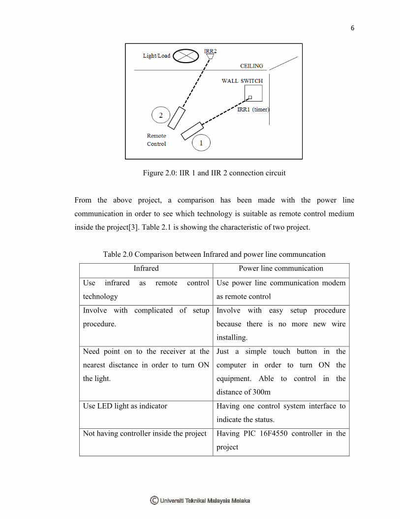
From the reviewed paper, the author wrote that infrared technology is being
used as switch in the home to switch on light. Through this, user need to point on the
infrared receiver (IRR1) to the wall that is mounted with timer, from there IRR1 then
only will transfer the logic ‗1‘ to another module IRR 2 that connects with the load. The
figure below is showing the overall concept of the project. [3]
6
Figure 2.0: IIR 1 and IIR 2 connection circuit
From the above project, a comparison has been made with the power line
communication in order to see which technology is suitable as remote control medium
inside the project[3]. Table 2.1 is showing the characteristic of two project.
Table 2.0 Comparison between Infrared and power line communcation
Infrared Power line communication
Use infrared as remote control
technology
Use power line communication modem
as remote control
Involve with complicated of setup
procedure.
Involve with easy setup procedure
because there is no more new wire
installing.
Need point on to the receiver at the
nearest disctance in order to turn ON
the light.
Just a simple touch button in the
computer in order to turn ON the
equipment. Able to control in the
distance of 300m
Use LED light as indicator Having one control system interface to
indicate the status.
Not having controller inside the project Having PIC 16F4550 controller in the
project
7
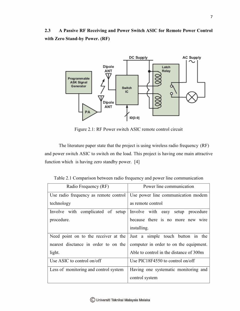
2.3 A Passive RF Receiving and Power Switch ASIC for Remote Power Control
with Zero Stand-by Power. (RF)
Figure 2.1: RF Power switch ASIC remote control circuit
The literature paper state that the project is using wireless radio frequency (RF)
and power switch ASIC to switch on the load. This project is having one main attractive
function which is having zero standby power. [4]
Table 2.1 Comparison between radio frequency and power line communication
Radio Frequency (RF) Power line communication
Use radio frequency as remote control
technology
Use power line communication modem
as remote control
Involve with complicated of setup
procedure.
Involve with easy setup procedure
because there is no more new wire
installing.
Need point on to the receiver at the
nearest disctance in order to on the
light.
Just a simple touch button in the
computer in order to on the equipment.
Able to control in the distance of 300m
Use ASIC to control on/off Use PIC18F4550 to control on/off
Less of monitoring and control system Having one systematic monitoring and
control system

8
2.4 Project 3: The Information Home Appliances Control System – A Bluetooth
Universal Type Remote Control (Bluetooth)
This project is work on the bluetooth remote control that able to control any
household appliances. The bluetooth range here can be reach till 100m with the addition
of antena. There will be two module developed in this project which is transmitter and
receiver. In the transmitter module is included keyboard, MCU and bluetooth module
while the receiver module comprise bluetooth module, MCU and load. The overall
concept can be shown at figure below. [5]
Figure 2.2: transmitter module
Figure 2.3: Receiver module
Table 2.2 Comparison between bluetooth and power line communication
Bluetooth Power line communication
Use bluetooth as remote control
technology
Use power line communication modem
as remote control
Involve with complicated of setup
procedure.
Involve with easy setup procedure
because there is no more new wire