Prototype Design and Manufacturing · PDF filePrototype Design and Manufacturing Manual Rev. 0...
64
PROTOTYPE DESIGN AND MANUFACTURING MANUAL DEPARTMENT OF MECHANICAL ENGINEERING RODNEY KATZ Rev. 0
Transcript of Prototype Design and Manufacturing · PDF filePrototype Design and Manufacturing Manual Rev. 0...

PROTOTYPE DESIGN AND MANUFACTURING MANUAL
DEPARTMENT OF MECHANICAL ENGINEERING
RODNEY KATZ Rev. 0

Prototype Design and Manufacturing Manual Rev. 0
i
TABLE OF CONTENTS
Introduction ................................................... 1
PART I - Design ............................................... 2
1 First Step to Design ............................. 2
2 Prototyping ......................................... 3
2.1 Example Prototype Device .......... 6
3 Top Down Machining .......................... 7
4 Alignment! .......................................... 9
4.1 Alternate Methods .................... 13
5 Bearings ............................................. 17
6 Motor ................................................ 17
7 O-rings ............................................... 18
8 Pipes and Tubes ................................ 21
8.1 Fittings for pipes ........................ 21
9 Materials ........................................... 22
9.1 Raw Materials ............................ 22
9.2 Aluminum ....Error! Bookmark not defined.
9.3 Steel ........................................... 23
9.4 PVC ............................................. 23
9.5 Delrin ......................................... 24
9.6 Plexiglas ..................................... 25
10 Drawings ........................................ 26
10.1 Common Drawing mistakes ....... 27
10.2 Dimensioning ............................ 27
10.3 Tolerances ................................. 35
10.4 Anilam CNC Mill ........................ 35
Part II - Manufacturing ................................ 39
1 Posts ................................................. 39
1.1 Important Notes for posts ........ 43
2 CNC Milling ....................................... 44
2.1 Setup methods .......................... 44
3 O-Rings ............................................. 48
3.1 Axial O-rings .............................. 48
3.2 Radial O-rings ............................ 51
4 Drilling and Tapping.......................... 54
4.1 Tapping ...................................... 54
Appendices ..................................................... I
References ...................................................... I

Prototype Design and Manufacturing Manual Rev. 0
1
INTRODUCTION
• The purpose of this manual is to present best practices for the design and
manufacturing of prototype devices, low volume machined parts and assemblies.
• It is important to note that many of the methods and techniques outlined in the manual
are specific to the UVic Mech. Machining Facility.
Figure 1.1 – Mixer device
• The manual is structured around the design and manufacturing of a single device
(shown above in Figure 1.1) which encompasses many typical characteristics of
mechanical features found in the Dept. Mechanical Engineering research apparatus.
• This design is very efficient to machine, incorporates inherent alignment, uses stock
material readily available in the machine shop and is familiar with the shop machinists.
• The manual will also include comparison examples of less effective designs of the same
device. These methods are often initially thought to be easier to fabricate but do not
lend the same advantages of the recommended sample design shown above
• Design methodology is a very broad subject; this manual only covers the basics.
• Extended topics like high volume manufacturing, rapid prototyping and techniques used
outside the Mech. Eng. Shop are not covered in this manual.

Prototype Design and Manufacturing Manual Rev. 0
2
PART I - DESIGN
1 FIRST STEP TO DESIGN
• Design of a device should always begin with opening communication with the specific
shop or facility where parts will be manufactured.
• The capabilities of the shop or facility need to be carefully considered in order to design
economically feasible devices or equipment:
o Machinery and shop specific expertise, CNC milling, lathe capability, sheet metal
capabilities, welding capabilities, heavy machining, precision grinding, waterjet
cutting, EDM, rapid prototyping, etc.)
o Shop preferred manufacturing methods and materials.
o Machine tool (lathe, mill) capacity. What is the largest or smallest size
workpieces and cutting tools the shop’s machines can comfortably
accommodate.
o Time line required to deliver parts.
• While in the design phase, continually communicating with shop personnel will always
lead to designs which are less expensive and more efficient to build.
• Whenever possible, design parts in inches. The rationale being the machine shop’s
cutting tool and material inventory are in the imperial (inch) system. Designing in metric
then converting to inches leads to odd dimensions thus complicating the design and
machining process, resulting in a more costly and time consuming part
• Always keep in mind stock material sizes when designing parts. This is paramount to
achieving an economically feasible design. Often the stock material size will be sufficient
to accommodate your design with little additional machining required. In Canada we
still work with stock material sizes in the inch system as most of our material comes
from U.S. suppliers.

Prototype Design and Manufacturing Manual Rev. 0
3
2 PROTOTYPING
• Generally prototype parts should incorporate the following:
o Inherent Alignment. Parts automatically fit into place. This eliminates the need
for post machining and hand tool modification in order to fit parts together.
Bosses and other features should be incorporated in the design to assure
alignment of final assemblies.
o Ability to be adjusted with little rework. This could mean adding extra holes or
elongating holes for unforeseen additions or when you may feel adjustability
could be required.
o The use of easily machinable material i.e aluminum, acetyl (Delrin), PVC (plastic)
where ever possible. Even though these materials may be twice or three times
the cost of steel, their fabricating and machining costs will be drastically lower
resulting in a less expensive part.
o Reduce the number of parts with tight tolerances (to lower cost and increase
machining efficiency).
o Size parts with a consideration for material yield. E.g. aluminum sheet comes in
48” X 96” sheets. If you require four pieces 12 ½” X 12 ½” this will result in much
waste material. Re-consider the design to work with 12” X 12” pieces. Sheet
metal does not consume material for cuts where as plate material (3/16” and
thicker) will consume approximately 3/16” per cut due to the sawing and clean-
up process. Plate material is also supplied in 12” increments. Therefore if four
12” X 12” plates are required this will produce a large amount of excess material.
Try to work the design with part sizes of 11.75” X 11.75”
o Tapped holes #6-32 and larger should be drilled all the way through in materials
up to ¾” thick if possible as opposed to holes drilled to specific depths. It is
always easier to tap a through hole opposed to a blind hole (hole that does not
penetrate). The hole may only be tapped partially through.
o When designing a hole for a pressfit dowel pin, incorporate a smaller diameter
through hole which can be used to push or knock the dowel pin out if required.

Prototype Design and Manufacturing Manual Rev. 0
4
This will often be the case. (See Fig. 2.1 below). If no through hole is present it
will be very difficult to remove the dowel pin and removal methods will result in
damaging the pin and the maybe the hole.
Figure 2.1 – Thru hole in shaft to allow removal of dowel pin
o Tabs or marks for realigning parts if they are going to be placed back in a
machine for post machining operations. This is often the case when the part
needs holes aligned to each other from both ends. Another reason for alignment
marks would be or if the part needs to be oriented in a specific rotational angle
at assembly time. (See Figure 2.2).
Figure 2.2 – Circular part and fixture with grooves for realignment
o Flats on round parts. This allows for the part to be replaced into a vise with a
known orientation for post machining or modifications at a later date from (See
Figure 2.3)
Dowel pin Shaft
Thru hole to push out dowel
Scratch marks for realignment

Prototype Design and Manufacturing Manual Rev. 0
5
Figure 2.3 – Round part with flat self aligns in vise
• Avoid welding parts together. Welding does not allow for major changes if required.
Separating parts can be very labour intensive and sometimes close to impossible. It is
also very difficult to accurately align welded parts.
• Design the assembly of sufficient size to avoid working in confined spaces. Also avoid
the use of tiny screws i.e. #2-56 and smaller.
• Try to keep the fastener thread type selection to a minimum. #10-32 is a very practical
size for much of the metal work performed in the shop and is easily tapped.
(use a #10-24 for plastics)
• Utilise as many off-the-shelf items as possible. These will save many hours of design and
machining work, paying for themselves many times over. Often off-the-shelf
components may not meet all the requirements but can be machined to accommodate
the design requirements.

Prototype Design and Manufacturing Manual Rev. 0
6
2.1 EXAMPLE PROTOTYPE DEVICE
• The mixer device shown in Figure 2.4 is the example prototype assembly.
• Key components, which will be discussed in the manual, are noted on the diagram.
Figure 2.4 – Mixer Device
Motor (gears drive main shaft)
Post
NPT Threaded Hole (Cylinder surface is spot faced)
Control Panel
Top Plate (Top-down machined)
NPT and ISO Fittings
O-ring seals
Bearings
Prototype Design and Manufacturing Manual Rev. 0
7
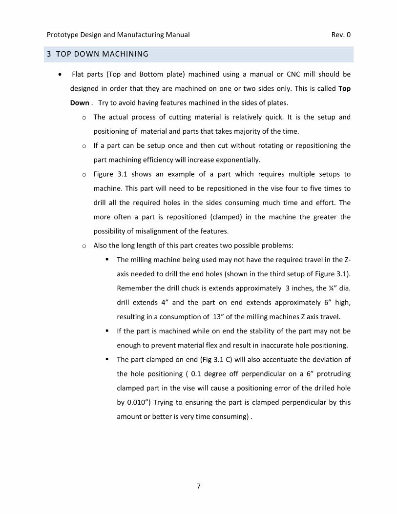
3 TOP DOWN MACHINING
• Flat parts (Top and Bottom plate) machined using a manual or CNC mill should be
designed in order that they are machined on one or two sides only. This is called Top
Down . Try to avoid having features machined in the sides of plates.
o The actual process of cutting material is relatively quick. It is the setup and
positioning of material and parts that takes majority of the time.
o If a part can be setup once and then cut without rotating or repositioning the
part machining efficiency will increase exponentially.
o Figure 3.1 shows an example of a part which requires multiple setups to
machine. This part will need to be repositioned in the vise four to five times to
drill all the required holes in the sides consuming much time and effort. The
more often a part is repositioned (clamped) in the machine the greater the
possibility of misalignment of the features.
o Also the long length of this part creates two possible problems:
The milling machine being used may not have the required travel in the Z-
axis needed to drill the end holes (shown in the third setup of Figure 3.1).
Remember the drill chuck is extends approximately 3 inches, the ¼” dia.
drill extends 4” and the part on end extends approximately 6” high,
resulting in a consumption of 13” of the milling machines Z axis travel.
If the part is machined while on end the stability of the part may not be
enough to prevent material flex and result in inaccurate hole positioning.
The part clamped on end (Fig 3.1 C) will also accentuate the deviation of
the hole positioning ( 0.1 degree off perpendicular on a 6” protruding
clamped part in the vise will cause a positioning error of the drilled hole
by 0.010”) Trying to ensuring the part is clamped perpendicular by this
amount or better is very time consuming) .

Prototype Design and Manufacturing Manual Rev. 0
8
Figure 3.1 – Multiple setups required for a part that cannot be machined TOP DOWN

Prototype Design and Manufacturing Manual Rev. 0
9
4 ALIGNMENT!
• Alignment of parts and features is one of the most important aspects of mechanical
design.
• If parts are designed with alignment in mind at all times it will prevent much frustration
and added cost in the final assembly.
Figure 4.1 – Post with end bosses and extra holes in OD
• One basic method to align parts is to use posts with bosses on both ends. Figure 4.1
shows an example of a post which incorporates bosses to aid alignment.
• Incorporating a boss on each side of the post has the added advantage of allowing the
post to be held in the lathe chuck so the critical length can be measured off the front
face of the chuck jaws (the “Z” datum).
• The procedure used in the shop for accurately machining this type of post design is very
efficient.
• Figure 4.2 shows how posts with integral bosses are used in the assembly.
Prototype Design and Manufacturing Manual Rev. 0
10
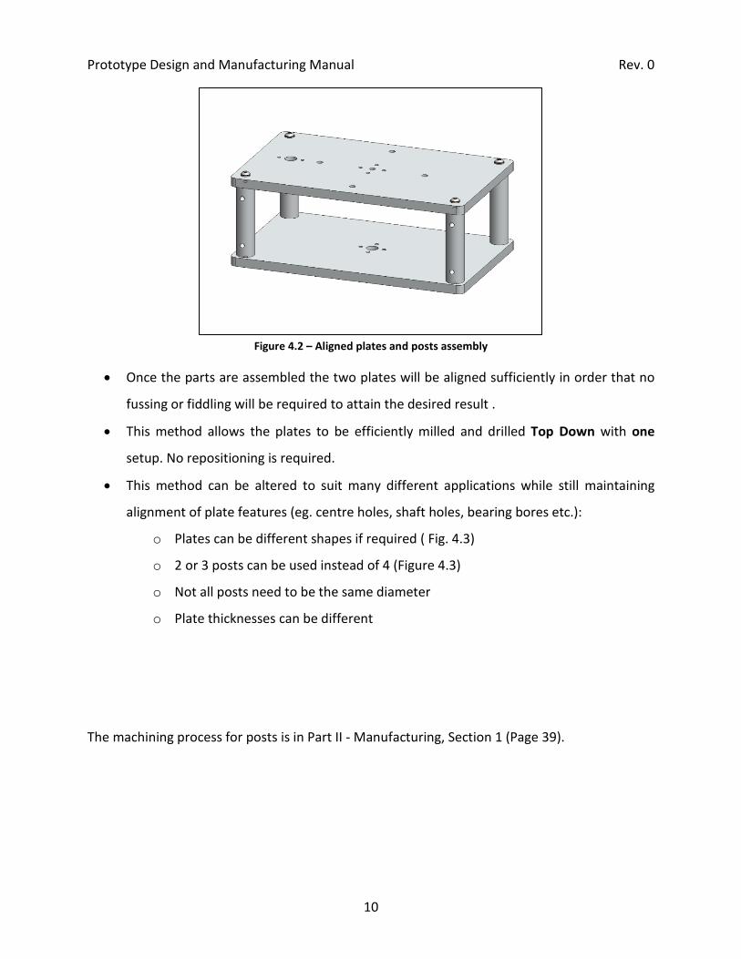
Figure 4.2 – Aligned plates and posts assembly
• Once the parts are assembled the two plates will be aligned sufficiently in order that no
fussing or fiddling will be required to attain the desired result .
• This method allows the plates to be efficiently milled and drilled Top Down with one
setup. No repositioning is required.
• This method can be altered to suit many different applications while still maintaining
alignment of plate features (eg. centre holes, shaft holes, bearing bores etc.):
o Plates can be different shapes if required ( Fig. 4.3)
o 2 or 3 posts can be used instead of 4 (Figure 4.3)
o Not all posts need to be the same diameter
o Plate thicknesses can be different
The machining process for posts is in Part II - Manufacturing, Section 1 (Page 39).

Prototype Design and Manufacturing Manual Rev. 0
11
Figure 4.3 – 3 post design with difference shaped plates

Prototype Design and Manufacturing Manual Rev. 0
12
Car chassis Tapping Machine
Table Submersible Chassis (fits in tube)
Winch 3 post design
Figure 4.4 – Examples of how posts can be used
• Figure 4.4 shows examples of how posts can be used. (eg. Car chassis, table, ROV, etc.)

Prototype Design and Manufacturing Manual Rev. 0
13
4.1 ALTERNATE METHODS
• This section presents some of the alternatives to using round posts with bosses. The
alternatives may appear easier to fabricate but are often much more time consuming to
machine and assemble and they do not incorporate inherent alignment features.
• Figure 4.5 shows a design similar to the recommended method
o The square posts are difficult to machine.
o Multiple setups are required to machine the posts.
Figure 4.5 – Plate assembly using square posts

Prototype Design and Manufacturing Manual Rev. 0
14
• Figure 4.6 and Figure 4.7 show the two plate assembly with angle brackets
• Angle brackets are appealing because they seem simple to machine (just cut to length
and drill). A note of caution! Often what appears simple to fabricate results in being
rather difficult and cumbersome. The method in Figure 4.6 is very time consuming to
machine as the top and bottom plates cannot be machined top down. A total of 64
holes must be drilled. Half of the holes also need to be tapped in the sides of the plates.
Figure 4.6 – Plate assembly using angle brackets
Unstable

Prototype Design and Manufacturing Manual Rev. 0
15
• The second angle bracket method uses welds.
o This assembly requires 16 welds . Considerable time is required to setup and
weld. Proper alignment of the plates will be virtually impossible often requiring
some post machining or hand work.
o In terms of prototyping welding does not allow parts to be easily modified.
Figure 4.7 – Plate assembly using welded angle brackets
• Figure 4.8 shows a welded version of a winch frame. The winch in Fig 4.8 would take a
considerable amount of time and effort to construct due of the number of welds and
the requirement that the frame be accurately aligned for bearings blocks.
Figure 4.8 – Welded Winch Frame

Prototype Design and Manufacturing Manual Rev. 0
16
NOTE: There is a time and place for welding but in most assemblies used in the Mech. Eng. Dept. it is not appropriate. Welding of small aluminum parts is very difficult and should be avoided.
• Figure 4.9 below shows the two plate assembly using C-channel. This method is appears
relatively quick to machine but has significant alignment limitations:
o C-channel comes in standard sizes therefore spacing of the plates has limited
options. Spacers must be used to adjust plate spacing.
o The size of extruded c-channel is not always accurate and the C-channel sides are
often not perpendicular.
o Ensuring the holes are drilled directly opposite one another in the C-channel is
very difficult.
o Securely holding the C-channel parts in the vice for drilling is cumbersome.
Figure 4.9 – Plate assembly using c-channel for posts

Prototype Design and Manufacturing Manual Rev. 0
17
5 BEARINGS
• Bearings of many varieties are often used in mechanical design and are of utmost
importance to the functionality of the assembly.
• Machined features that accept bearings must usually be made to tighter tolerances than
other features.
• If a bore hole for a bearing is too small requiring excess force to seat the bearing it will
often cause the bearing to run rough and lead to premature failure.
• If a bore hole is too loose the bearing will slop around and reduce the alignment of the
shaft .
• Always include tolerances in drawings for dimensions related to bearings.
• If possible have the bearings available at time of machining. This will greatly help the
machinist correctly size the bearing bore hole.
6 MOTOR MOUNTING
• Most small and midsize motors incorporate a boss and bolt holes on their face (Figure
1.1).
• The motor’s boss assures concentric alignment of the motorshaft to the mounting
surface.
• Correct tolerancing of the boss receiving bore is very important. If possible have the
motor available to the machinist to check the bore size and fit at time of machining. This
will often avoid time consuming rework of parts.

Prototype Design and Manufacturing Manual Rev. 0
18
•
Figure 6.1 – Motor with boss and bolt holes
7 O-RINGS
• O-rings are one of the most common types of seals used. They are extremely efficient
and very inexpensive. The machining processes required to accommodate O-rings is
often simple if the part is designed with consideration.
• Sealing using O-rings allows for easy disassembly of the apparatus if modifications or
cleaning is required.
Figure 7.1 – O-rings
Boss
Bolt holes

Prototype Design and Manufacturing Manual Rev. 0
19
• Types of O-Ring Sealing Configurations
o Axial: o-ring seal is on the face of a part.
o Radial: o-ring seal is on the outer or inner wall of a part. Radial seals on small
shafts can significantly decrease the strength of the shaft. In this case it is better
to groove the inner diameter of the part the shaft will fit into.
o Avoid the use of Radial O-ring configurations if possible, they are more difficult
to machine and require much tighter tolerances in all respects. Note that the
Plexiglas O-ring container configuration in the sample Mixer device uses an axial
seal. There are several reasons for this choice:
o It is easier to machine vs. a radial seal. If a radial seal were used, the Plexiglas
container I.D. would have to be accurate and concentric. This is often not the
case in stock tubular material. In order to attain an accurate and concentric I.D.
on a tube it must be bored on a lathe which is very time consuming. For an axial
seal only the ends of the container need to be machined which is a quick process
o A radial seal is often makes it difficult to remove the end caps especially in
oceanographic instruments.
Figure 7.2 Axial O-Ring seal Radial O-Ring seal

Prototype Design and Manufacturing Manual Rev. 0
20
Figure 7.3 Axial gland Radial gland
• The groove in which the O-Ring sits is called the “gland” (fig 7.3)
• Appendix V and VI show tables for gland sizes.
• The machining process for O-ring glands is in Part II - Manufacturing, Section 3
(Page 48).

Prototype Design and Manufacturing Manual Rev. 0
21
8 PIPES AND TUBES
• Pipes: Pipe sizes are referred to based on their nominal inner diameters, not their outer
diameters. i.e. a ¾” schedule 40 pipe will have an O.D. of 1.050”
o Note: The nominal inner diameter of pipe usually does not match the physical
inner diameter. This is due to the different wall thicknesses (referred to as
schedule sizes i.e sched. 40 or sched. 80). Different pipe materials have different
O.D. sizes i.e. ¾” copper pipe has an O.D. of 0.875” vs. ¾” steel and aluminum
pipe having an O.D. of 1.050”.
• Tubes: Tube sizes are referred to based on their actual physical O.D. i.e. 1” tube is
physically 1.00” O.D.
• Pipe is often less expensive than tube therefore it is used when larger quantities are
required in the design or when fluid transport is required. Tube is used when a specific
diameter is required.
8.1 PIPE AND FLUID FITTINGS
The following are the most common fluid fittings used in the Mech. Eng. Dept. research apparatus
• NPT (National Pipe Thread) is a standard for pipe fittings. NPT fittings are tapered to
produce an effective friction seal when screwed into the mating fitting.
Note: A ¼” NPT fitting has thread O.D. of approximately 1/2”.
NPT fittings are not used in thin material or sheet metal. A minimum of four threads
must be engaged to produce a reliable seal.
• ISO fittings have straight threads and incorporate an O-ring in the base to create a seal.
The mating surface for these o-rings must always be spot-faced to produce a reliable
seal. See the offset hole in the top cap of the sample device. The spot face is required to
produce a surface with machining marks concentric with the O-ring seal. If this is not
done the striations or any scratches in the plastic plate would allow a leak. Whenever
O-rings are used any machining marks or scratches must be concentric with the O-ring.

Prototype Design and Manufacturing Manual Rev. 0
22
9 MATERIALS
• This section lists some of the more common materials used in the UVic Mech. Eng.
Machine Shop. Consult McMaster-Carr (www.mcmaster.com) for more detailed
information on the material sizes, characteristics and cost.
9.1 STOCK MATERIALS
• When designing keep in mind the standard sizes of stock materials.
o In most cases stock materials cannot be depended on for accurate sizes or
geometric tolerances (perpendicular sides, parallelism, etc.)
o An example exception is precision ground steel rod which is ground to tight
tolerances.
o If high precision alignment is required the stock material must often be machined
on the significant mating surfaces. Aluminum plate has good surface flatness as
opposed to aluminum extrusion and is approximately twice the price. Use of
aluminum plate can often reduce the amount of machining required paying for
itself in the final result.
9.2 ALUMINUM
Aluminum is most often the material of choice in the Mech. Eng. Machining Facility.
• Aluminum Characteristics and Advantages
o Lightweight
o Large size selection
o Good strength
o Good corrosion resistance
o Easy to machine
o Clean to work
o Good esthetics

Prototype Design and Manufacturing Manual Rev. 0
23
o High heat conductivity
o Easily recyclable
o Readily available
o Difficult to weld properly
o Can be anodized to achieve a very highly corrosion resistant surface and coloured
surface.
9.3 STEEL
• Mild Steel Characteristics
o High strength
o Heavy
o Corrodes easily (rust)
o Easy to Weld
o Certain types of steel prove difficult to machine
o Low cost
o Considerably more costly to machine than aluminum
• Mild steel is not used extensively in the Mech. Eng. Machining facility. It is generally
used for shafts, heavy welded structures, axels etc.
• Stainless Steel characteristics
o Very good corrosion resistance ( Oceanographic applications)
o High temperature
o Very high strength
o Very heavy
o Expensive
o Welds easily
o Costly to machine, use only where absolutely necessary
9.4 PVC PLASTIC

Prototype Design and Manufacturing Manual Rev. 0
24
• PVC characteristics:
o Good corrosion resistance
o Easy to machine
o Lightweight
o Can be bonded easily. Note: A mechanical interconnectivity of the two parts is
always required when bonding PVC. It is not advisable to butt joint PVC.
o Not recommended for wear applications due to high friction coefficient.
9.5 DELRIN (ACETAL)
• Delrin (Acetal) is often used as a replacement for aluminum parts. Due to its excellent
machinability try to implement it into designs where possible. One major advantage
being that it does not need any coating to be corrosion proof. It also produces very
esthetically pleasing parts due its sheen and colour.
• Delrin (Acetal) has the following characteristics:
o Excellent machinability
o Corrosion proof
o Good relative strength
o Lightweight
o Tough and wear resistant
o Very low friction coefficient
o Solvent and fuel resistant
o White or black in colour
o Commonly available in round rod/bar, sheet, and plate
• Some applications of Delrin:
o Bushings for low speed applications
o Wear pads
o Fluid fittings
o Gears , pulleys, idlers
• Important Notes:

Prototype Design and Manufacturing Manual Rev. 0
25
O Delrin cannot easily be bonded to itself or other materials.
9.6 PLEXIGLAS
• Plexiglas characteristics:
o Lightweight
o Optically clear
o Brittle
o Scratches easily
o Low operating temperature band
o Commonly available in sheet, tube and solid round
o Bonds to itself very easily
• Plexiglas can be bent using heat.
o Bending Plexiglas is not recommended for prototype design because changes
and adjustments cannot be made.
o Accurately heat bending Plexiglas is can prove to be difficult.
Plexiglas can be easily bonded together with a butt joint resulting in relatively strong
bond (Figure 9.1).
o Surfaces must be smooth and flat for bonding Plexiglas i.e. routed or milled.
Figure 9.1 – Plexiglas bonded butt joint

Prototype Design and Manufacturing Manual Rev. 0
26
10 DRAWINGS
• Try to always include an assembly view with a set of submitted drawings.
o This will help the shop understand the purpose of the parts and where extra care
should be taken when machining. If tolerances or dimensions were omitted in a
drawing it will often allow the shop to make an informed judgment if they are
not able to contact you.
• Make sure the drawing scale is noted so if dimensions need to be checked or are missing
they can be measured off the drawing.
• When prototyping, printing drawings with a 1:1 scale can be useful to see the affects of
changes on the part.
• General information should be included in the drawing title block. An example title
block is shown in Figure 10.1.
o Details to include: scale, quantity, material, part #, contact info, tolerances
Figure 10.1 – Example Title Block

Prototype Design and Manufacturing Manual Rev. 0
27
10.1 COMMON DRAWING MISTAKES
• Too many decimals places
• Dimensions referenced from wrong side of part edge
• Font to big or too small (should be 12 pt. → 14 pt.)
• Arrow heads too big
• Too many hidden lines shown making drawing difficult to interpret (use a section view if
needed to show hidden details)
• Too much information on one drawing sheet (use more than one drawing sheet to show
part more clearly if this is the case)
10.2 DIMENSIONING
• Use ordinate dimensioning to make drawings easier to read.
• Mark the origin of a part based on the origin which will be used when the part is
machined.
• Draw ordinate lines on the side of the part which is closest to the detail they are
showing the position of.
• The following pages show examples of drawings which are cluttered and difficult to
understand followed by a drawing which uses best practices for dimensioning drawings.
• Dimension drawing features according to the shop preferred method or specific CNC
mill that will be used. (See section 10.4 Anilam CNC Mill, page 35)

Prototype Design and Manufacturing Manual Rev. 0
28
Figure 10.2 – Ordinate Dimensioning
3.000
2.625
0 1.00
0
.375
1.62
5
2.87
53.
000
3.18
8
.500
4.75
05.
000
0.250.500
1.000
2.000
3.25
0
1.250
1.635
.260
.375 THRU 3PL
.250 THRU 3PL
1.000 THRU
R.300 TYP
.250 NOM

Prototype Design and Manufacturing Manual Rev. 0
29
3.000
2.625
0 1.00
0
.375
1.62
5
2.87
53.
000
3.18
8
.500
4.75
05.
000
0.250.500
1.000
2.000
3.25
0
1.250
1.635
.260
.375 THRU 3PL
.250 THRU 3PL
1.000 THRU
R.300 TYP
.250 NOM

Prototype Design and Manufacturing Manual Rev. 0
30
4.7503.188
5.000
.250
1.000 THRU
2.875
.260
R.300 TYP1.635.5001.000
.3751.000
1.625
3.000
THRU 3PL.250
3.250
.500
THRU 3PL.375
2.000
1.000
2.625
.250
1.250
3.000
Figure 10.3 – Example of baseline dimensioning

Prototype Design and Manufacturing Manual Rev. 0
31
Notes about drawing (Figure 10.3)
• Use of baseline dimensions makes drawing too cluttered and hard to read
:
• Elevation view shown with hidden lines is confusing. Should have hidden lines removed.
• Slot length dimension should be done to the total length of slot (as shown below).
.260
1.375
.25
Undesirable slot dimensioning
.260
1.635
.25
Preferred slot dimensioning style
Figure 10.4 – Dimensioning of a slot length

Prototype Design and Manufacturing Manual Rev. 0
32
Notes about drawing
• Dimension lines are difficult to follow. Ordinate dimensions should be on the side of the
part closest to the feature they are defining (shown in
:
Figure 10.7).
• Elevation view of part should be shown without hidden lines (Figure 10.5).
.250 NOM
↓
.250 NOM
Figure 10.5 – Elevation view with and without hidden lines
• Dimension lines should not touch the part.
.260
↓
.260
Figure 10.6 – Dimension line spacing

Prototype Design and Manufacturing Manual Rev. 0
33
1.2500
3.25
0
1.00
0
4.75
05.
000
3.18
8
0.250
1.0001.000
2.000
2.625
3.000
.375
1.62
5
2.87
5
.500
3.00
0
.500
.260
1.635
1.000 THRU
.375 THRU 3PL
R.300 TYP
.250 THRU 3PL
.250 NOM
Figure 10.7 – Easy to read drawing using ordinate dimensions

Prototype Design and Manufacturing Manual Rev. 0
34
Desirable drawing characteristics
• The drawing above uses the preferred style of dimensioning.
:
• Dimension lines are spaced apart to avoid cluttering the drawing.
• Dimensions are close to the feature they describe.
• The slot’s centre position is dimensioned and the width and total length are shown.

Prototype Design and Manufacturing Manual Rev. 0
35
10.3 TOLERANCES
• Tolerances are a very important aspect of drawings which are often overlooked and are
not given the attention they require.
All dimensions should have an associated tolerance. An efficient tolerancing method includes a section to the drawing sheet’s title block which defines the standard tolerances based on number of decimal places (shown in
• Figure 10.8).
Tolerances .xxx ±0.003 .xx ±0.01 .x ±0.015 Unless otherwise noted
Figure 10.8 – Drawing Block for Standard Tolerances
• If certain dimensions can accommodate wider tolerance then remove the appropriate
decimals. When specifically needed add tolerances to individual dimensions to highlight
the precision required.
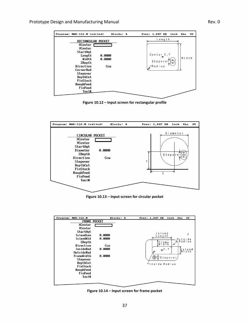
10.4 ANILAM CNC MILL
• The CNC Milling machine used extensively in the Mech. Eng. Machine Shop utilises an
Anilam control system.
• The following figures show the control system’s different input screens (conversational
programming) for various canned cycles.
o A canned cycle is a set of machine operations initiated by a single line of code. It
uses a “fill in the blank” type interface.
• Use the screens shown below to determine the appropriate method to dimension part
features which will be CNC milled (diagrams are specific to Anilam control system).

Prototype Design and Manufacturing Manual Rev. 0
36
Figure 10.9 – Input screen for bolt hole circle
Figure 10.10 – Input screen for rectangular profile
Figure 10.11 – Input screen for circular profile
Prototype Design and Manufacturing Manual Rev. 0
37
Figure 10.12 – Input screen for rectangular profile
Figure 10.13 – Input screen for circular pocket
Figure 10.14 – Input screen for frame pocket

Prototype Design and Manufacturing Manual Rev. 0
38
10.4.1 ANILAM CANNED CYCLE DEFINITIONS
• Profile: Circular or Rectangular. CNC mill cuts the outline of the shape. Cutter can be on
the inside or outside of the shape. Profiles are used for milling the outside contours,
slots and holes.
• Pocket: Circular or Rectangular. CNC mill cuts all of the material inside of the shape to a
specified depth.
• Frame: CNC mill cutsa rectangular groove. This can have any radius on the corners
(commonly used for rectangular o-ring grooves).
• Note: All these cycles require the shape’s centre position, length, width or diameter,
therefore it is most helpful to dimension drawings with these requirements in mind.

Prototype Design and Manufacturing Manual Rev. 0
39
PART II - MANUFACTURING
1 POSTS
• The drawing below (Figure 1.1) shows the best practices for dimensioning a post
drawing when using the machining method outlined on the following pages.
3.75
0.25
3.50
0
.5
.750 - .002+.000
2 PL1/4-20
1.0 NOM
UVic Faculty of EngineeringHole Tapper
Drawn by REV.
SCALE: 1:1 MATERIAL:
MLDate:
SHEET 1 OF 1
Part: Qty.
A
1
7/22/2009
Comments:Dimensions in inchesunless noted.
Tolerances:.xxx .003.xx .010.x .015unless otherwise stated
Project:
Standoff
Break all sharp edges
Figure 1.1 – 2D Drawing for Post
• The post drawing above shows the datum position (“zero”) as the base of the left boss.
This is done because the critical dimension for this part is 3.500” and not the overall
length of 4.0”.
• Note: If alignment is very critical (eg. top and bottom plates need to be aligned within
±0.003 of each other) then the outer diameter of the post must be machined first to
maintain concentricity throughout the machining process. This is because stock material

Prototype Design and Manufacturing Manual Rev. 0
40
is often not perfectly round. Machining the full outer diameter length is rarely required
in most applications.
• Lathe process for machining multiple posts with bosses
Step 1 – Face first end of post and set Z-axis to
zero on lathe digital readout
Step 2 – Turn boss to required diameter and approximate depth.
Step 3 – Centre drill
Step 4 – Drill end to tap depth

Prototype Design and Manufacturing Manual Rev. 0
41
Step 5 – Tap. Repeat steps 1-5 for all posts
Step 6 – Zero tool against chuck using shim (make
sure to account for shim thickness)
Step 7 – Face opposite end of post to
approximately the total length
Step 8 – Centre drill. Repeat steps 7 and 8 for all identical posts
Step 9 – Turn second boss with live centre
(Z = critical length of post)
Step 10 – Drill boss of opposite end to tap depth
Z

Prototype Design and Manufacturing Manual Rev. 0
42
Step 11 – Tap second end Step 12 – Chamfer all sharp edges

Prototype Design and Manufacturing Manual Rev. 0
43
1.1 IMPORTANT NOTES FOR POSTS
• The overall length need not to be machined as accurately as the critical length between
the bosses (shown in step 9).
• When turning the boss in step 2 it can be beneficial to leave the boss extra long. This
gives the the chuck jaws more surface area to clamp when turning with the live centre.
After step 9 the this extra length can be faced off easily.

Prototype Design and Manufacturing Manual Rev. 0
44
2 CNC MILLING
2.1 SETUP METHODS
2.1.1 FLAT PARTS
• Flat parts are often machined on a CNC mill using a fixture plate (Shown below). This has
many advantages over conventionally machined part.
o If the part does not have any features in its ends or sides only one setup is
required (Top-down machining). This being the rationale for not placing holes in
the sides of flat parts when it can be avoided.
o The outside of the part can be machined in one step.
o Precise copies of the same part can be rapidly machined (i.e. left and right sides,
top and bottom).
Figure 2.1 – Flat part with fixturing plate
Fixture plate
Part

Prototype Design and Manufacturing Manual Rev. 0
45
Figure 2.2 – Fixturing plate setup in vise
2.1.2 CIRCULAR PARTS
• When the milling forces will be in the Z-axis only (eg. Drilling) a circular part can be
bolted down to a plate (Shown in Figure 2.3).
Figure 2.3 – Circular Part bolted down through center.

Prototype Design and Manufacturing Manual Rev. 0
46
• In other cases where lateral and radial cutting forces will be applied to the part a jig can
be used. Figure 2.4 shows an example of a very simple, effective circular holding jig
which is commonly used in the shop. The scratch marks on the part and jig allow the
part to be replaced into the mill in the correct orientation for post machining operations
or modifications.
Figure 2.4 – Circular part with jig

Prototype Design and Manufacturing Manual Rev. 0
47
Figure 2.5 – Circular part and jig setup

Prototype Design and Manufacturing Manual Rev. 0
48
3 O-RINGS
3.1 AXIAL O-RINGS
• Reduce RPM speeds when grooving
• Figure 3.1 shows an example axial o-ring groove.
.100±.005 2.50 NOM
1.580±.003
1.750±.003
Figure 3.1 – Axial O-ring Groove
1. Determine the width of the tool being used. In this case the tool width is 0.0525”.
2. Using the following formula, determine the ‘X’ position for the O.D. of the O-ring groove
Prototype Design and Manufacturing Manual Rev. 0
49
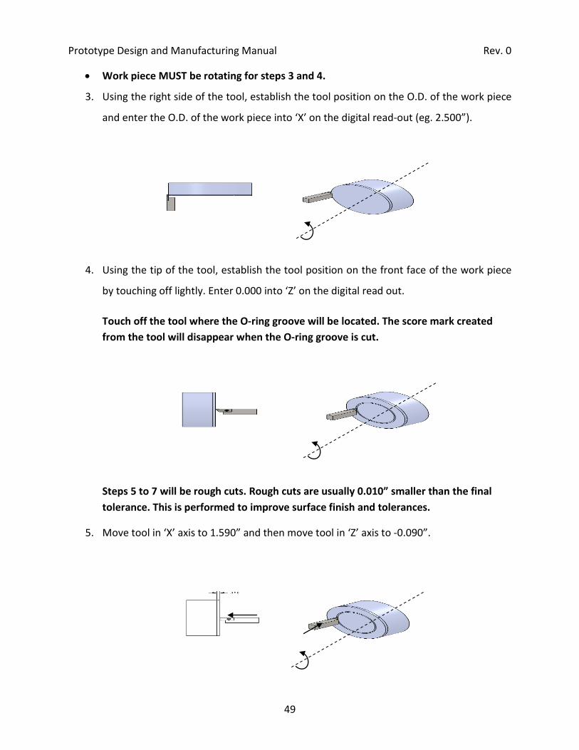
• Work piece MUST be rotating for steps 3 and 4.
3. Using the right side of the tool, establish the tool position on the O.D. of the work piece
and enter the O.D. of the work piece into ‘X’ on the digital read-out (eg. 2.500”).
4. Using the tip of the tool, establish the tool position on the front face of the work piece
by touching off lightly. Enter 0.000 into ‘Z’ on the digital read out.
Touch off the tool where the O-ring groove will be located. The score mark created from the tool will disappear when the O-ring groove is cut.
Steps 5 to 7 will be rough cuts. Rough cuts are usually 0.010” smaller than the final tolerance. This is performed to improve surface finish and tolerances.
5. Move tool in ‘X’ axis to 1.590” and then move tool in ‘Z’ axis to -0.090”.

Prototype Design and Manufacturing Manual Rev. 0
50
6. Move tool in ‘X’ axis out to 1.635”. This is 0.010” smaller than the calculated value from
step 2.
7. Perform the finishing cut. Move ‘X’ to 1.580”, next move ‘Z’ in to -0.100” and then move
‘X’ out to 1.625”.
This should be done in one fluid motion. The tool should never become stationary on the work piece when performing any cuts. This can cause chatter and excessive heat generation and when machining plastic it will create a poor surface finish and the seal may leak.

Prototype Design and Manufacturing Manual Rev. 0
51
3.2 RADIAL O-RINGS
• Reduce RPM speeds when grooving
• Figure 3.2 shows an example radial o-ring groove.
.145±.005
.250
1.50 NOM
1.320±.003
Figure 3.2 – Radial O-ring Groove
1. Determine the width of the tool being used. In this case the tool width is 0.0525”.
2. Use the following formula to determine the final ‘Z’ position for the width of the O-ring
groove.

Prototype Design and Manufacturing Manual Rev. 0
52
• Work piece MUST be rotating for steps 3 and 4.
3. Using the left side of the tool, establish the tool position on the end of the work piece
and enter the width of the tool into ‘Z’ on the digital read-out (eg. 0.0525”). This
established the right side of the tool as zero in the ‘Z’ axis.
4. Using the tip of the tool, establish the tool position on the O.D. of the work piece and
enter the O.D. of the work piece into ‘X’ on the digital read out. (eg. 1.500”)
Touch off the tool where the O-ring groove will be located. The score mark created from the tool will disappear when the O-ring groove is cut.

Prototype Design and Manufacturing Manual Rev. 0
53
Steps 5 to 7 will be rough cuts. Rough cuts are usually 0.010” smaller than the final tolerance. This is performed to improve surface finish and tolerances.
5. Move tool in ‘Z’ axis to -0.260” and then move tool in ‘X’ axis to 1.320”.
6. Move tool in ‘Z’ axis to -0.333”. This is 0.010” smaller than the calculated value from
step 2.
7. Perform the finishing cut. Move ‘Z’ to -0.250”, next move ‘X’ in to 1.300” and then move
‘Z’ to -0.343”.
This should be done in one fluid motion. The tool should never become stationary on the work piece when performing any cuts. This can cause chatter and excessive heat generation and when machining plastic it will create a poor surface finish and the seal may leak.

Prototype Design and Manufacturing Manual Rev. 0
54
4 DRILLING AND TAPPING
• Centre Drill:
o Use anytime there is a chance the drill bit may glance off the material or when
holes need to be precisely positioned (ie. holes on a radius, drilling into a hard
material, etc.). Centre drills are used very often when drilling in the lathe.
• Drilling Plexiglas:
o Plexiglas will often to crack when the drill bit exits through the other side of the
part. To prevent this, slow down the drill feed for the last 1mm or 1/16” while
drill bit exits the material. This heats the Plexiglas to make the last 1/16” more
pliable to prevent cracking. Use extra care when drilling holes greater than 5/16”
diameter.
4.1 TAPPING
• Taps: Used to cut internal threads. The various types of taps are:
Spiral point taps are the most commonly used. The first 3 to 4 threads on these taps are partial therefore they do not cut full threads for the complete length of engagement. If this is required see Bottoming taps below.
o Bottoming Tap: Used to cut threads to the bottom of a blind hole. A bottoming
tap does not have a tapered cutting edge therefore a plug tap must be used first.
Do not use a bottoming tap to cut threads in an unthreaded hole.
• Tap drill bit: Specific sized drill bit for a certain tap (eg. #6 drill for a 1/4-20 tap).
• Percentage of Thread: The percentage of thread refers to the amount of thread in terms
of the total thread depth (crest to root). Use a larger tap drill bit to lower the thread
percent and vice versa. Decreasing the thread percent minimizes the torque on the tap
and dramatically helps to avoid breaking the tap. It also speeds up the threading pro
Note: Use a bottoming tap only when thread depth is critical (ie. 1/2” plate requiring 3/8” thread depth). Regular taps will not cut full threads to the bottom of a hole.

Prototype Design and Manufacturing Manual Rev. 0
55
Figure 4.1 – Thread percentage example
• TPI: Threads Per Inch
• Metric threads are specified by the distance between the threads
• Die (external threads): Used to cut external threads.
• NPT Threads: (National Pipe Thread) These are tapered threads for sealing fluids
• Maximum depth of tapped holes should not exceed 3 X Diameter of Tap. Usaully twice
the tap diameter is all that is required to provide maximum holding force.
100 % Thread 70 % Thread 50 % Thread
Crest Root

Prototype Design and Manufacturing Manual Rev. 0
I
APPENDICES
Machining Tolerances II
Tap Drill Sizes III
Drilling and Milling Speeds IV
O-Ring Gland Sizes (Axial) V
O-Ring Gland Sizes (Radial) VI

Prototype Design and Manufacturing Manual Rev. 0
II

Prototype Design and Manufacturing Manual Rev. 0
III
Tap drill and body drill sizes (from shop)

Prototype Design and Manufacturing Manual Rev. 0
IV
Drilling, milling speeds (from shop)

Prototype Design and Manufacturing Manual Rev. 0
V

Prototype Design and Manufacturing Manual Rev. 0
VI

Prototype Design and Manufacturing Manual Rev. 0
I
REFERENCES
Osborn, Joe. 2006. Tips on Designing Cost Effective Machined Parts. [Online] OMW Corporation. Available at: http://www.omwcorp.com/partdesign.html. [Accessed 19 June 2009].
McMaster-Carr. 2009. [Online] McMaster-Carr Supply Company. Available at: http://www.mcmaster.com. [Accessed 07 August 2009].
Parker O-Ring Handbook ORD 5700, Parker, 2007.
http://www.parker.com