
Software Reviews & testing Software Reviews & testing An Overview.

Protocol Software Engineering:Protocol Testing
Kimmo Raatikainen & Oriana Riva
Department of Computer Science
29.1.2007© Kimmo Raatikainen & Oriana Riva 2
Lesson Outline
Some protocol testing methodsR. Lai: A survey of communication protocol testing. The Journal of Systems and Software 62 (2002) 21–46.
Example: VoIPRuibing Hao, David Lee, Rakesh K. Sinha, and Nancy Griffeth: Integrated System Interoperability Testing WithApplications to VoIP. IEEE/ACM Transactions on Networking, Vol. 12, No. 5 (October 2004) 823-836.
Testing SDLAna R. Cavalli, Byoung-Moon Chin, and Kilnam Chon: Testing methods for SDL systems. Computer Networks and ISDN Systems 28 (1996) 1669-l 683.

29.1.2007© Kimmo Raatikainen & Oriana Riva 3
A survey of communication protocol testing
29.1.2007© Kimmo Raatikainen & Oriana Riva 4
Introduction …
A protocol is a precise set of rules that defines the interaction among elements of a system.
Protocol conformance testing seeks to ensure that such elements will operate correctly once the system has been implemented by checking that the protocol implementation conforms to the specification.
29.1.2007© Kimmo Raatikainen & Oriana Riva 5
... Introduction...
Formal Description Techniques (FDTs) have been developed to provide a formal specification acting as a sound basis for protocol testing.
e.g., Specification and Description Language (SDL)
Standardized procedures for protocol testing have been developed by ISO
The standard ISO 9646 defines the details for Conformance Testing Methodology and Framework (CTMF).A test notation called Tree and Tabular Combined Notation (TTCN) has also been developed.
29.1.2007© Kimmo Raatikainen & Oriana Riva 6
… Introduction …
Academic research has recently made significant advances
in the generation of test sequences from formal specifications andin the development of computer-aided test tools to improve the effectiveness of testing
This state-of-the-art research is not necessarily state-of-the-practice

29.1.2007© Kimmo Raatikainen & Oriana Riva 7
… Introduction
There is not much progress in the use of test sequence generation techniques for practical testing of communication networks.Test design is still largely performed by testers by interpreting the specifications written in a natural language.Testers have to face real problems such as deadlines, resource and economic constraints.The big gap between academic and industrial testing practices is the fact that academia has not been addressing the real-life testing issues and problems account for the fact that academic testing methods are seldom used in industry.

29.1.2007© Kimmo Raatikainen & Oriana Riva 8
Background knowledge
Graphs
Finite state machine
Extended finite state machine
Distinguishing sequences
Characterizing sequences
Unique input/output (UIO) sequences
29.1.2007© Kimmo Raatikainen & Oriana Riva 9
Graphs …
Let G = (V,E) be a labelled directed graph with vertex set V edge set E
V = {v1; . . . ; vn} and m = |E|.
In general, G may contain loops and multiple edges, which are distinguished from one another by different labels.An edge from vertex vi to vj is represented by a triple (vi, vj; Lk), where Lk is a distinct label.A walk in G is a finite non-null sequence of consecutive edges
W = {(vi,1, vi,2; L1)(vi,2, vi,3; L2) ... (vi,r-1, vi,r ; Lr-1)}
29.1.2007© Kimmo Raatikainen & Oriana Riva 10
… Graphs …
A tour is a walk that starts and ends at the same vertex.
An Euler tour of G is a tour which contains every edge of E exactly once.
Graph G is strongly connected if for any pair of distinct vertices vi and vj there exists a walk W in G with origin vi
and tail vj
G is weakly connected if the underlying undirected graph is connected
29.1.2007© Kimmo Raatikainen & Oriana Riva 11
… Graphs
A postman tour of G is a tour which contains every edge of E at least once.
The Chinese Postman Problem is to find an optimal (minimum cost) postman tour of a directed, strongly connected graph G
such a tour is called a Chinese Postman Tour.
If G contains an Euler tour, the Euler tour is also a Chinese Postman Tour.
29.1.2007© Kimmo Raatikainen & Oriana Riva 12
Finite state machine
A finite-state machine (FSM) M can be represented by a directed graph G = (V,E)
the set V = {v1; . . . ; vn} of vertices represents the set of
specified states, S, of the FSM, and
a directed edge represents a transition from one state to
another in the FSM
A specification of an FSM is said to be fully specified if, for every state, every input in the input set of M generates an output.Otherwise, the specification is said to be partially specified.
29.1.2007© Kimmo Raatikainen & Oriana Riva 13
Extended finite state machine …
The extended finite state machine (EFSM) is introduced as a remedy to the state space explosion problem of the FSM in specifying large, practical protocols involving context variables, such as sequence numbers.
An EFSM is an FSM augmented with minor states (context) variables.
These variables form additional enabling conditions in the transitions to reduce the number of states required in the underlying FSM.

29.1.2007© Kimmo Raatikainen & Oriana Riva 14
… Extended finite state machine …
Different transitions may occur in response to the same combination of input event and starting (major) state in an EFSM.
A transition in an EFSM may be triggered by three types of enabling conditions:
the input event,
the current (major) state, and
a boolean expression involving minor state variables.
29.1.2007© Kimmo Raatikainen & Oriana Riva 15
… Extended finite state machine …
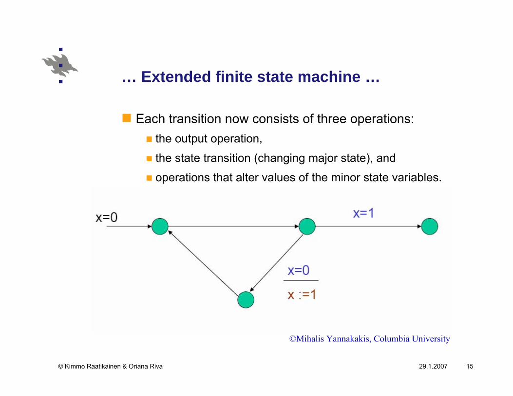
Each transition now consists of three operations:the output operation,
the state transition (changing major state), and
operations that alter values of the minor state variables.
©Mihalis Yannakakis, Columbia University
29.1.2007© Kimmo Raatikainen & Oriana Riva 16
… Extended finite state machine
Test sequences generated from an FSM are generally done according to their directed graphs.
Since minor state variable need to be considered as well in an EFSM to ensure the final test sequences are executable, when these variables are included in an extended directed graph, can become very cluttered and difficult to use.
The tabular format is better suited for representing an EFSM for testing purposes and is also used as a tool for test sequence generation procedure.

29.1.2007© Kimmo Raatikainen & Oriana Riva 17
Distinguishing sequences
A distinguishing sequence is defined as a set of inputs that generate a set of outputs different for each starting state si in an FSM.
For generating a test sequence by using the distinguishing sequences method, first a distinguishing sequence for the FSM to be tested is found based on the specification.
Note that it is necessary for an FSM to be fully specified for having a distinguishing sequence.
29.1.2007© Kimmo Raatikainen & Oriana Riva 18
Characterizing sequences
For the FSMs that do not have distinguishing sequences, the characterizing sequences method defines partial distinguishing sequences each of which distinguishes a state si from a subset of the remaining states instead of distinguishing si from every state of the FSM.
The complete set of such input sequences for an FSM is called the characterizing set W of the FSM.
This method, similar to the distinguishing sequences method, requires a fully specified FSM.
29.1.2007© Kimmo Raatikainen & Oriana Riva 19
Unique input/output (UIO) sequences …
A UIO sequence for a state si is an input/output behaviourthat is not exhibited by any other state:
UIO(si) = (i1/ o1)(i2 / o2)…(ip / op)
UIO sequences are not the same as distinguishing sequences.
For a test, the input portion of distinguishing sequence is the
same for all states; different states are distinguished by the
distinct output.
For the UIO sequences, the input portion is normally
different for each state.
29.1.2007© Kimmo Raatikainen & Oriana Riva 20
… Unique input/output (UIO) sequences …
When the input part of the UIO sequence for a certain state s is applied to the FSM, the output sequence is compared with the expected output sequence.
If they are the same, then the FSM is in state sOtherwise, the FSM is not in state s
When the input portion of a distinguishing sequence is applied to the FSM, the outputs contain sufficient information to decide not only whether the machine is in state s but also if not s, then which one.

29.1.2007© Kimmo Raatikainen & Oriana Riva 21
… Unique input/output (UIO) sequences
UIO sequences are typically shorter than the distinguishing sequences or characterizing sequences since the UIO sequences are a subset of them.
Also, almost all FSMs have UIO sequences unless the FSM has equivalent states
29.1.2007© Kimmo Raatikainen & Oriana Riva 22
Test sequence generation methods
As implementation can be different from a protocol standard, conformance testing is needed to confirm the implementations to its standard.
Testing is carried out by using test sequences.A test sequence is a list of inputs and expected outputs.
Four formal methods (T-, U-, D- and W- method) have been presented for generating test sequences for protocol from a protocol specification.All four methods assume a Mealy machine model (M) for protocol entity specifications.
29.1.2007© Kimmo Raatikainen & Oriana Riva 23
Mealy machine
A Mealy machine is an FSM which produces an output upon each transition
Let M represent a Mealy machine and adopt the following notation:
M|s ≡ machine M at state s;M|s(α) ≡ the last output symbol on input string α to M|s;M|s<α> ≡ the output string on input string α to M|s.
29.1.2007© Kimmo Raatikainen & Oriana Riva 24
Some definitions …
Definition 1: A machine M is minimal if the number of states of M is less than or equal to the number of states of M’ for any Mealy machine M’ equivalent to M.
Definition 2: A machine is completely specified if from each state it has a transition for each input symbol. M is incompletely specified if it is not completely specified.
Definition 3: A machine M is strongly connected if from each state pair (si,sj) there is a transition path going from si to sj.
29.1.2007© Kimmo Raatikainen & Oriana Riva 25
… Some definitions …
Definition 4: A transition table of M is a table consisting of two subtables: an output subtable and a next-state subtable, each with rows and columns identified by the states and input symbols of M, respectively. An entry in the output (next-state) subtable specifies, corresponding to a state s and an input symbol A of M, the output (next-state) of M|s on A.
Definition 5: A test subsequence for M is a sequence of input symbols for testing either a state or a transition of M.
29.1.2007© Kimmo Raatikainen & Oriana Riva 26
… Some definitions
Definition 6: A test sequence for M is a sequence of input symbols that can be used in testing conformance of implementations of M against the specification of M.
Definition 7: A β – sequence for M is a concatenation of test subsequences for testing all transitions of M.
Definition 8: An optimized test sequence is a test sequence such that no subsequence of it is completely contained in any other subsequence.
29.1.2007© Kimmo Raatikainen & Oriana Riva 27
The T-Method …
The T-method assumes a minimal, strongly connected, and completely specified M.
A test sequence, called a transition-tour sequence can be generated by simply applying random inputs to a fault-free M until the machine has traversed every transition at least once.
However, the sequence generated may contain many redundant inputs which in turn generate loops in the transition tour.
29.1.2007© Kimmo Raatikainen & Oriana Riva 28
The U-Method …
The U-method assumes a minimal, strongly connected and completely specified Mealy machine.
It involves deriving a unique input/output (UIO) sequence for each state of M.
A UIO sequence for a state of M is an I/O behavior that is not exhibited by any other state of M.
A UIO sequence can be used to determine whether the FSM was in a specified start state or not.
29.1.2007© Kimmo Raatikainen & Oriana Riva 29
… The U-Method
However, if the FSM was in some other (error) state, it will not be possible to determine the identify of that using a UIO sequence.
Optimized test sequence can be obtained by applying the Rural Chinese Postman Tour
29.1.2007© Kimmo Raatikainen & Oriana Riva 30
The D-Method
The D-method assumes a Mealy machine which is minimal, strongly connected, completely specified and possesses a distinguishing sequence.
An input string x is said to be a distinguishing sequenceof a machine M if the output string produced by M in response to x is different for each starting state.
The key idea of this method is to compute a distinguishing sequence (if it exists) for a machine M.

29.1.2007© Kimmo Raatikainen & Oriana Riva 31
The W-Method
The W-method assumes a minimal, strongly connected, and completely specified Mealy machine.
It involves deriving a characterization set W of the FSM.
A characterization set W for M is a set consisting of input strings α1, . . . , αk such that the last output symbols observed from the application of these strings (in a fixed order) are different at each state of M.
29.1.2007© Kimmo Raatikainen & Oriana Riva 32
Comparison …
A test sequence generated by the T-method can be used to confirm the existence of transitions but it cannot test the tail states of the transitions.Regarding the U-method, a state can be uniquely identified by observing the output string produced by the application of the input string from its UIO sequences.In contrast to an application of the D-method, a state can be identified by observing distinguishing sequence for a Mealy machine.Set W for machine M enables easy identification for each state of M based on the W-method.

29.1.2007© Kimmo Raatikainen & Oriana Riva 33
… Comparison …
Since most protocols are not completely specified, conformance is defined at two levels:
weak and strong conformance.
An implementation has strong conformance to the specification if both generate the same outputs for all input sequences.An implementation has weak conformance to a specification if the implementation has the same input/output behaviour as the protocol specification consisting of core edges only.
it has unspecified behavior for the input-state combinations
specified by those non-core edges.
29.1.2007© Kimmo Raatikainen & Oriana Riva 34
… Comparison …
The fault detection capabilities of the weak and strong conformance test sequences generated can be stated as follows:
The fault coverage of the weak conformance test sequence
for the U-method is better than the fault coverage of the
weak conformance test sequence for the T-method.
The fault coverage of the strong conformance test sequence
for the U-, D-, and W-methods is better than the fault
coverage of the strong conformance test sequence for the T-
method.
The fault coverage of the strong conformance test sequence
for the U-, D-, and W-methods are the same.
29.1.2007© Kimmo Raatikainen & Oriana Riva 35
Some conclusions …
All of these four methods assume minimal, strongly connected and fully specified Mealy machine models of protocol entities.
On the average, the T-method will produce the shortest test sequence and the W-method the longest test sequence among the four methods, while D- and U-methods generate test sequence of comparable lengths.
T-method weak conformance test sequences are able to detect faults in output labels but not in tail states of transition edges.
29.1.2007© Kimmo Raatikainen & Oriana Riva 36
… Some conclusions
U-method weak conformance test sequences can detect both kinds of single faults but not combinations of fault in some cases.
For strong conformance testing, T-method test sequences show the same behavior as that method’s weak conformance counterpart while U-, D- and W-method test sequences are capable of detecting all kinds of faults and give the same performance.
29.1.2007© Kimmo Raatikainen & Oriana Riva 37
The UIO method …
Since the 1980s, UIO sequences have been widely used to ensure that protocols conform to their specification.
Some limitations of the approaches will occur when UIOsand signatures are not unique in an implementation because they may not detect erroneous final states in the implementation
29.1.2007© Kimmo Raatikainen & Oriana Riva 38
… The UIO method …
The UIOv-method has been presented in order to ensure that these erroneous states are captured.
The use of partially Unique Input/Output (PUIO)sequences, and a more efficient algorithm for generating a UIO sequence for any given state have been proposed.
29.1.2007© Kimmo Raatikainen & Oriana Riva 39
... Approaches using UIO sequences
The UIOSs-method
Rural Chinese Postman method
Multiple UIO method
Overlaps method
Multiple UIO and overlaps method
The UIOv-method
Discriminating UIO sequences
29.1.2007© Kimmo Raatikainen & Oriana Riva 40
The UIOSs-method …
In the past, checking experiments were based on the existence of distinguishing sequences, which are I/O sequences capable of identifying each of the states in an FSM.
Only a limited number of FSMs have distinguishing sequences.
UIOSs were proposed to be used in checking experiments.An UIOS for a state is an I/O behavior not exhibited by any other state.
29.1.2007© Kimmo Raatikainen & Oriana Riva 41
… The UIOSs-method …
The advantages of UIOs are that they are generally shorter than distinguishing sequences.
In practice, nearly all FSMs have UIOs for each of their states.
29.1.2007© Kimmo Raatikainen & Oriana Riva 42
… The UIOSs-method
The input sequence of the distinguishing sequences for all the states in the FSM are identical, but each output sequence is different and it depends on the state; hence, states can be identified by outputs they generate.
For UIOSs, the input sequence may be different for different states so that these states can be identified according to its inputs as well as its outputs.
If the input sequence happens to be identical for different states, then each of these states must again produce different output sequences in order to be distinguishable.
29.1.2007© Kimmo Raatikainen & Oriana Riva 43
Rural Chinese Postman method
The method uses the Rural Chinese Postman (RCP)problem in graph theory to minimize the transfer sequence between subsequences.
It opened a new direction for optimization research.Other optimization methods are basically extensions of this
method.
The RCP problem is NP-complete for the most general case, but when the edge-induced subgraph G|EC| is weakly connected, it can be solved in polynomial time. When G|EC| is not weakly connected, heuristics will have to be used to find sub-optimal solution.
29.1.2007© Kimmo Raatikainen & Oriana Riva 44
Multiple UIO method …
Multiple UIO sequences are a set of minimal length UIOsfor a state.
It was found that using different UIOs for identifying a state in different subsequences can reduce the length of the overall test sequence.
This is because by selecting the appropriate UIOs, the graph G|EC| can be made closer to symmetry,
the difference of in-degrees and out-degrees for a vertex
may be smaller, thereby fewer edges from E are needed to
augment it.
29.1.2007© Kimmo Raatikainen & Oriana Riva 45
Overlaps method …
The overlapping between subsequences is considered to further minimize the test sequence.
A single UIO sequence is used.
The idea is that if two subsequences S1 and S2 are overlapped, then they can be merged with the overlapping part serving both S1 and S2.
29.1.2007© Kimmo Raatikainen & Oriana Riva 46
… Overlaps method
The problem is how to maximally exploit the overlapping.
There is a technique to transform the problem into a minimum cost maximum cardinality matching problem in a bipartite graph.
Some heuristics are then used to connect them.
29.1.2007© Kimmo Raatikainen & Oriana Riva 47
Multiple UIO and overlaps method …
This technique combines multiple UIO sequences and overlaps to fully exploit the properties of the subsequences and yield the shortest test sequence.
A machine is called definitely diagnosable if it has no converging edges
no two edges going into the same state with the same input
output label.
29.1.2007© Kimmo Raatikainen & Oriana Riva 48
… Multiple UIO and overlaps method …
In this case, the test sequence is simply an Euler tour of the FSM graph G plus the UIO sequence for the last state of the tour.
The rationale is that for such machines, the test sequence not only tests each transition but also serves as the characterizing sequence for each state visited.
29.1.2007© Kimmo Raatikainen & Oriana Riva 49
… Multiple UIO and overlaps method
If converging edges exist, a graph G’ is constructed by removing the converging edges.Then a set of disjoint paths in G’ that covers all edges is completed.The problem becomes how to join these disjoint paths and the converging edges such that the total length is minimal.
UIO sequences are used both for joining the paths and also
identifying the states along the paths.
It turns out that such a problem can be converted to a
maximum cardinality minimum cost matching problem for a
bipartite graph.
29.1.2007© Kimmo Raatikainen & Oriana Riva 50
The UIOv-method
The protocol specification, from which test sequences are generated, consists of control and data portions.
The control portion is typically modelled as a finite-state
machine, FSM, while the data portion is typically modeled as
program segments in so-called EFSMs.
The UIOv method is extended to handle both control and data portions.The UIOv method added a verification procedure in order to ensure that the UIO sequences are all unique in an implementation.The UIOv-method is fully applicable to protocols modeled by completely specified finite state machines.
29.1.2007© Kimmo Raatikainen & Oriana Riva 51
Discriminating UIO sequences …
This approach is based on the ability of constructing test subsequences in order to uniquely distinguish edges in the traversal of the FSM.
This is accomplished by selectively concatenating additional edges to each test subsequence.
The new test subsequence can distinguish not only the partial behavior of the original edge under test, but also the end state of any additional edge.
The process can be iteratively continued to further reduce the number of tests.
29.1.2007© Kimmo Raatikainen & Oriana Riva 52
… Discriminating UIO sequences …
The main advantages of this approach are that:The number of subsequences is considerably reduced with
respect to the number of test subsequences required in the
β-approximation.
Multiple edges can be concentrated prior to the execution of
a test subsequence in a β-approximation.
No fault coverage is lost.
29.1.2007© Kimmo Raatikainen & Oriana Riva 53
… Discriminating UIO sequences
Main ResultsA discriminating test subsequence can be constructed by
iteratively finding an edge which discriminates the head state
of any edge considered prior to the edge under test.
No fault coverage degradation occurs compared to a test
sequence generated by a traditional UIO method.
29.1.2007© Kimmo Raatikainen & Oriana Riva 54
Test coverage
Several studies have tried to find out how to measure the goodness of a set of test cases and how to generate or select test suites with some good coverage measure.
Fundamental problems in conformance testing are:how to generate a generic (super) test suite to ‘‘fully’’ cover a
given protocol specification within the space and time
resources available,
how to select a subset of test cases from a given generic
test suite to maximize the coverage,
how to determine the coverage of a given test suite, a given
protocol specification or its derived generic (super) test suite.

29.1.2007© Kimmo Raatikainen & Oriana Riva 55
The Multi-level approach …
In the multi-level approach, the key idea is to use a combination of methods to generate the entire test sequence.
different portions of the test sequence are generated using
different methods.
The specification graph is split into several disjoint subgraphs called
basic subgraph,
level 1 subgraph,
level 2 subgraph, etc.
29.1.2007© Kimmo Raatikainen & Oriana Riva 56
… The Multi-level approach …
The basic subgraph is chosen to represent the most important behavior of the protocol.
Edges of the remaining subgraphs correspond to behavior given in the specification, but not included in any of the other subgraphs.
Initially, only edges belonging to the basic subgraph are checked.
Edges in other subgraphs are checked only if the basic subgraph is correct.
29.1.2007© Kimmo Raatikainen & Oriana Riva 57
… The Multi-level approach …
The test subsequence for each subgraph is obtained by applying one of the test generation methods that is most suitable.
The complete test consists of subjecting the implementation to the level 0 test, the level 1 test and so on, in that order.
A level j test can be undertaken only after levels 0 to j-1 are
tested.
Any behaviour that is used in preamble and post-amble portions of a level j test, should have been verified to be correct in a lower level test.

29.1.2007© Kimmo Raatikainen & Oriana Riva 58
… The Multi-level approach …
It is mandatory that the level 0 (basic subgraph) test is successfully checked in an implementation, before higher level tests are applied.
If an implementation fails in a level 0 test, then it does not conform to the basic requirements of the specification and hence higher level tests are not conducted.
if any of the higher level tests fail, the test can continue.
29.1.2007© Kimmo Raatikainen & Oriana Riva 59
… The Multi-level approach
Test sequences generated using this approach have a high degree of fault coverage and capability to recover from errors.
The method does not assume the existence of an error-free reset input to move a protocol finite state machine from any state to an initial state.
29.1.2007© Kimmo Raatikainen & Oriana Riva 60
The E-method …
Extended transition tour (E-method) is proposed for generating test sequences for communication protocols modeled as finite machines.
The principle behind the E-method is to verify that the behavior corresponding to each incoming edge and outgoing edge of every state in the implementation, is similar to that of the specification.
29.1.2007© Kimmo Raatikainen & Oriana Riva 61
… The E-method …
Each state in the FSM is characterized by a set of transition pairs.
The methods to test the conformance of an implemented protocol, with respect to its specification, consists of checking whether the behavior corresponding to all the transition pairs in the implementation is the same as that of the specification
29.1.2007© Kimmo Raatikainen & Oriana Riva 62
… The E-method
Test sequences generated using the E-method are typically much longer than those generated by other methods but have a better fault coverage.
The E-method can be usedto generate test sequences for protocol FSMs which are
very sparse graphs or
to test certain limited behavior of protocols (subgraphs of a
protocol FSM).
29.1.2007© Kimmo Raatikainen & Oriana Riva 63
Fault models
A software failure is caused by a fault, which is a defect in the executable software product.
It is important to find out how many faults each module contains.
Important fault models in protocol testing:Finite state machinesState machines with input queuesPetri nets
29.1.2007© Kimmo Raatikainen & Oriana Riva 64
Type of faults in finite state machines…
Output faultThe machine provides an output different from the one
specified by the output function.
Transfer faultThe machine enters a different state than that specified by
the transfer function.
29.1.2007© Kimmo Raatikainen & Oriana Riva 65
… Type of faults in finite state machines …
Transfer faults with additional statesIn most cases, one assumes that the number of states of the
system is not increased by the presence of faults.
Certain types of errors can only be modeled by additional
states, together with transfer faults which lead to these
additional states.
29.1.2007© Kimmo Raatikainen & Oriana Riva 66
… Type of faults in finite state machines
Additional or missing transitionsIn many cases, it is assumed that the finite state machine is
deterministic and completely defined, i.e., for each pair of
present state and input there is exactly one specified
transition.
In the case of incompletely specified machines, no transition
may be specified for a given pair, while in the case on non-
deterministic machines, more than one transition may be
defined.
In these cases, the fault model could include additional
and/or missing transitions.
29.1.2007© Kimmo Raatikainen & Oriana Riva 67
State machines with input queues
In many situations, a system is described in the form of one or several state machines which are combined with input queues.
An input event is stored within the queue of the receiving machine before it is processed by the latter, usually in FIFO order.
Certain models assume that a given machine may have several input queues, which correspond to different sources of input events.
29.1.2007© Kimmo Raatikainen & Oriana Riva 68
The types of faults considered in state machines with input queues …
Ordering faultA machine has an ordering fault in relation with its input
queues if the FIFO ordering is not preserved, or if in the
case of multiple input queues, some input event enters a
wrong input queue.
Maximum length faultA machine has a maximum length fault if the maximum
length implemented is less than the one specified, or if an
input event may get lost while the number of submitted input
events does not overflow the maximum queue length
specified.

29.1.2007© Kimmo Raatikainen & Oriana Riva 69
The types of faults considered in state machines with input queues
Flow control faultA machine has a flow control fault if errors of ordering or of
loss occur, but only in case the number of submitted input
events overflows the maximum queue length specified.
29.1.2007© Kimmo Raatikainen & Oriana Riva 70
Petri nets …
A Petri net consists of a number of places, which may contain zero, one or more tokens, and a number of output arcs, each connecting the transition with a place.
A transition may fire if all places which are connected by input arcs contain at least one token
When the transition fires, one token is removed from these places, and one token is added to those places which are connected by an output arc.
29.1.2007© Kimmo Raatikainen & Oriana Riva 71
… Petri nets
A single Petri net may be used to model a system of interconnected finite state machines.
The states of the FSM correspond to certain places of the Petri net, and each different type of input or output is modeled by another place which may contain the input or output event in the form of a token.
The output and transfer faults of an FSM correspond to the fault of a Petri net where one of the output arcs of the transition leads to the wrong place.
29.1.2007© Kimmo Raatikainen & Oriana Riva 72
The types of faults considered in Petri net
Input or output arc faultA transition has an input or output arc fault if one of the input
or output arcs is connected to the wrong place, if an input or
output arc is missing, or if an input or output arc exists in
addition to those specified.
Missing or additional transitionA Petri net has a missing or additional transition if the
number of transitions is not the same as in the specification.
29.1.2007© Kimmo Raatikainen & Oriana Riva 73
Software Environments …
Protocol testing is playing a more and more essential roleit provides a means of enhancing the interoperability and
reliability of communication software
Many software environments for protocol testing have been developed
They have helped protocol testing to become more efficient,
reliable and flexible
29.1.2007© Kimmo Raatikainen & Oriana Riva 74
… Software Environments
On the next slide there is a list of some of the software tools for protocol testing
Lai’s survey gives brief introductions of some environments
that are related to protocol testing
In practice, protocol testing without any software tool is good enough only in tiny examples
29.1.2007© Kimmo Raatikainen & Oriana Riva 75
Some Software Environments for protocoltesting
TESTLTESTGENTESTGEN+: TESTGEN, TESTSEL, TESTVALUCB Environment: a test suite generator (TSG), a testcase management system (TCMS), a trace analyzer(TAN) and a test executor (TEX)TENTFAITHFORESTCVOPSPROSITESELEXPERT
29.1.2007© Kimmo Raatikainen & Oriana Riva 76
Summary of test sequence generation methods …
T-method: Uncomplicated
U-method: Involving UIO sequences
D-method: Involving a distinguishing sequence
W-method: Involving a characterization set W
UIOSs-method: Based on UIO sequences
RCP-method: Minimizing the transfer sequence between subsequences
29.1.2007© Kimmo Raatikainen & Oriana Riva 77
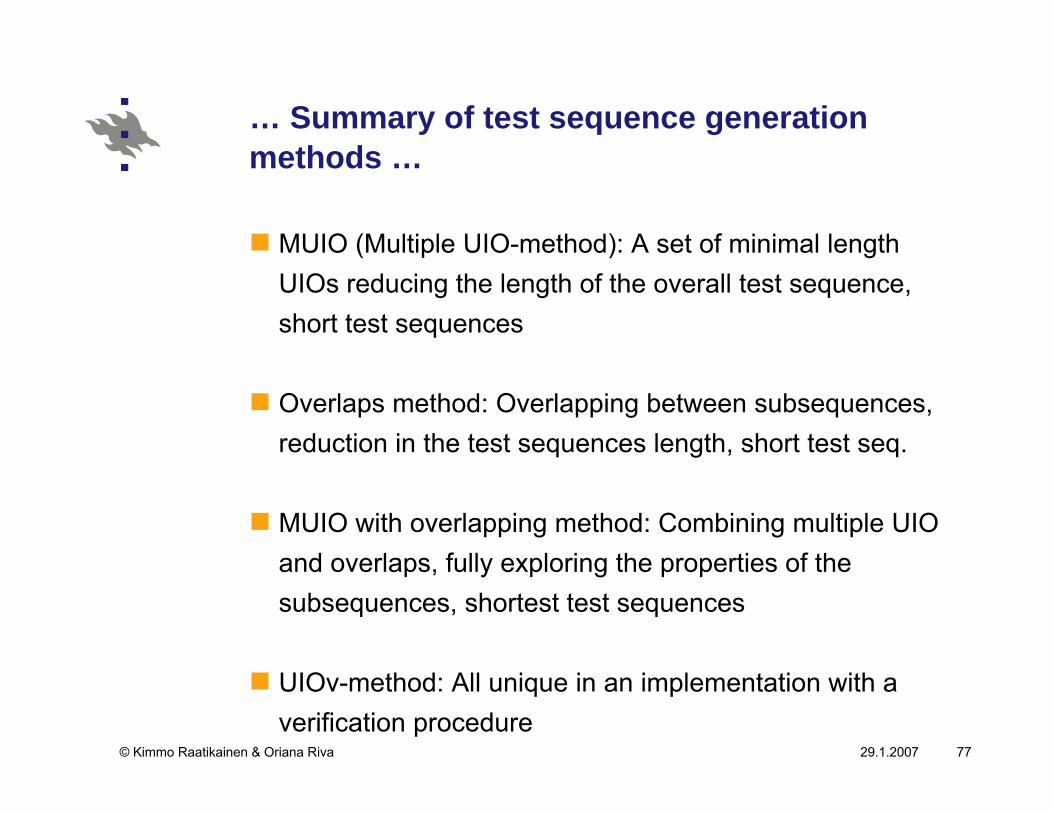
… Summary of test sequence generation methods …
MUIO (Multiple UIO-method): A set of minimal length UIOs reducing the length of the overall test sequence, short test sequences
Overlaps method: Overlapping between subsequences, reduction in the test sequences length, short test seq.
MUIO with overlapping method: Combining multiple UIO and overlaps, fully exploring the properties of the subsequences, shortest test sequences
UIOv-method: All unique in an implementation with a verification procedure

29.1.2007© Kimmo Raatikainen & Oriana Riva 78
… Summary of test sequence generation methods …
Discriminating UIO sequences: Based on the ability of constructing test sequences, uniquely distinguishing edges in the traversal of the FSM, reducing the number of test subsequences, no loss fault coverage
Multi-level method: Combining of several methods to generate the entire test sequence, high degree of fault coverage and capability to recover from errors
E-method: Characterized by a set of incoming edges and outgoing edges, good fault coverage
29.1.2007© Kimmo Raatikainen & Oriana Riva 79
Break
29.1.2007© Kimmo Raatikainen & Oriana Riva 80
Integrated System Interoperability Testing With Applications to VoIP
29.1.2007© Kimmo Raatikainen & Oriana Riva 81
Introduction …
When two or more entities in separate communicating systems are integrated and need to interact with each other to perform a certain task the capability to operate as desired is called interoperability
Products from different vendors or even from the same vendor often do not interoperate properly
Two main causes of noninteroperation are:ambiguity of protocol specification, and
vendor’s proprietary extensions.

29.1.2007© Kimmo Raatikainen & Oriana Riva 82
… Introduction …
Interoperability testing is to check the interoperations among integrated system implementations.
conformance testing that checks the conformance of the
implementation of a protocol to its specification
In conformance testing, the implementation under test is usually residing in an isolated environment for the tester to execute the test
29.1.2007© Kimmo Raatikainen & Oriana Riva 83
… Introduction …
In interoperability tests, the implementations are usually residing in an open environment
the degree of interoperation between implementations
depends not only on the implementations themselves but
also on the environment
The research work on interoperability testing can be roughly classified into two categories:
general concepts and experiences of interoperability testing,
and
systematic generation of interoperability test suites.

29.1.2007© Kimmo Raatikainen & Oriana Riva 84
… Introduction
Most of the recent research work in this field is related to interoperability test suite derivation.
One approach for interoperability test generation is to apply conformance test generation techniques on composed finite state machines (constructed from several components systems via a reachability analysis)
Problem: we may not have complete information on all the interoperating systems.
In VoIP systems, we can model end user behavior and H.323 protocols, but we do not have a specification of the communication systemthe IP network is too complex to model.
29.1.2007© Kimmo Raatikainen & Oriana Riva 85
The work of Hao et al. …
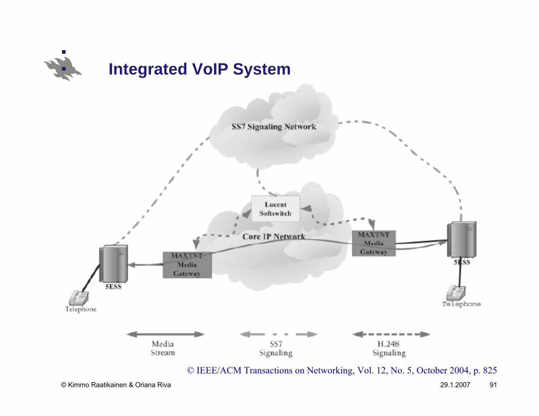
Motivated by the need to test interoperability of systems carrying voice calls over the IP network
The VoIP system must be integrated and interoperate with
the existing public switched telephone network (PSTN).
The system behavior is modelled by extended finite state machines (EFSM).
Based on the experiences of domain experts, a key idea in developing the coverage criteria is that interoperability errors are introduced only when the integrated systems are “interacting” with each other.

29.1.2007© Kimmo Raatikainen & Oriana Riva 86
… The work of Hao et al.
For instance, for VoIP interoperability testing, we only need information about end users required behaviors and H.323 interfaces.
The designed the ITIS (Interoperability Testing Intelligent System) software tool.
Using IT IS, interoperability test cases were generated for:End users versus the rest of the communication system; and
End users and H.323 versus the rest of the communication
system
29.1.2007© Kimmo Raatikainen & Oriana Riva 87
Interoperability Test Generation …
Interoperability testing is rather complexthere are different models for different applications and
system implementation environments
A common type of interoperability testing is usually performed on two interconnected implementations from different vendors (implementations A and B)
29.1.2007© Kimmo Raatikainen & Oriana Riva 88
… Interoperability Test Generation …
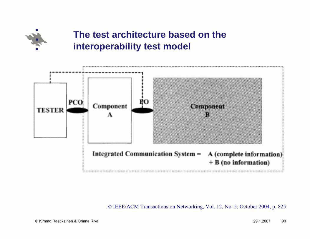
In the model of the article, there is an integrated system consisting of
system components of which we have complete information
(A)
system components of which we don’t have or choose not to
have information (either it is not available or too complex to
model) B
We can only access the systems through the interface with A.
29.1.2007© Kimmo Raatikainen & Oriana Riva 89
… Interoperability Test Generation
We can apply inputs to A and observe its corresponding output responses and its interoperations with while they are interoperating
Note that the output responses of A include its local outputs as a system component itself and also its interfaces with B, such as sending messages to and receiving messages from B.
29.1.2007© Kimmo Raatikainen & Oriana Riva 90
The test architecture based on the interoperability test model
© IEEE/ACM Transactions on Networking, Vol. 12, No. 5, October 2004, p. 825
29.1.2007© Kimmo Raatikainen & Oriana Riva 91
Integrated VoIP System
© IEEE/ACM Transactions on Networking, Vol. 12, No. 5, October 2004, p. 825

29.1.2007© Kimmo Raatikainen & Oriana Riva 92
Restrictions
Because of the limited controllability and observability in the test architecture it is a rather intriguing problem for fault identification.
we do not intend to solve the problem of identifying where
the faults are in the network.
In practice, usually we deploy some traffic sniffers in the network to record the packet exchange which could be used at a later time for a manual analysis and diagnosis.
29.1.2007© Kimmo Raatikainen & Oriana Riva 93
Notes …
Interoperability and conformance testing are closely related but different.
Given a system specification A and an implementation A’, which is a “black-box”, we want to apply a test to A’ to conclude whether it conforms to the specification A
A’ is identical to A.
In the interoperability testing, we want to test the interoperations between the system components A and B
we have complete information and control of A and no
information of B.

29.1.2007© Kimmo Raatikainen & Oriana Riva 94
… Notes
By a rationale similar to the case of conformance testing, ideally, we want to apply all the possible executable sequences as tests to A to trigger all the possible interoperations between A and B
the interoperations which can be controlled and observed by applying tests to A only.
In general, there are infinitely many such tests.So we want to reduce the tests to finitely many and minimize the number of tests yet maintaining the same coverage on interoperations between A and B, which are triggered by the tests.We need to explore the redundancy criteria and use efficient test generation algorithms.
29.1.2007© Kimmo Raatikainen & Oriana Riva 95
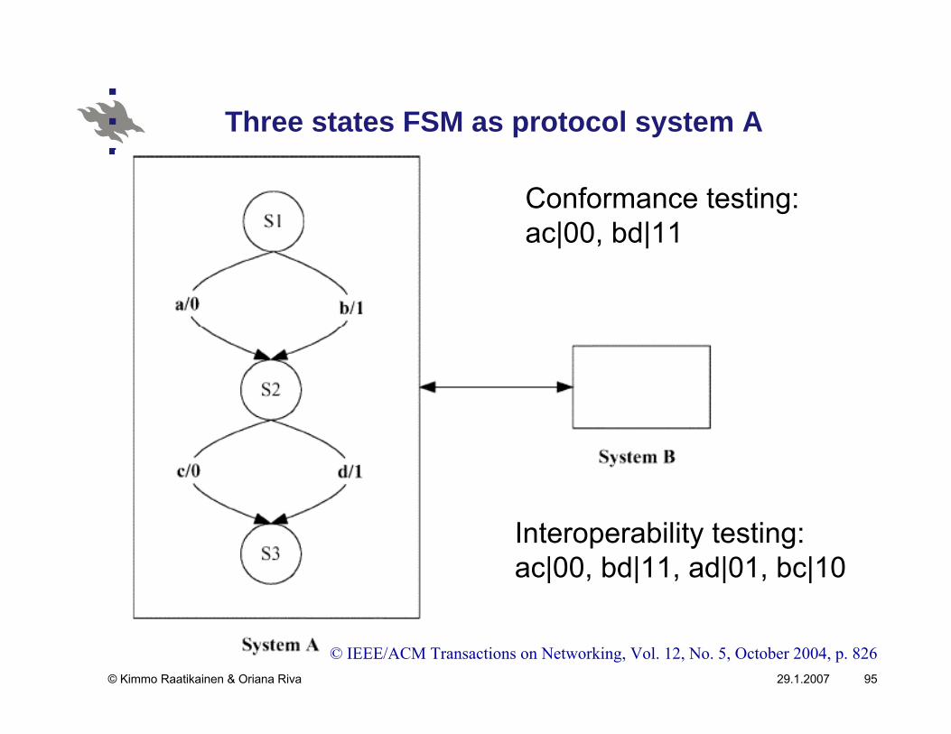
Three states FSM as protocol system A
© IEEE/ACM Transactions on Networking, Vol. 12, No. 5, October 2004, p. 826
Conformance testing:ac|00, bd|11
Interoperability testing:ac|00, bd|11, ad|01, bc|10
29.1.2007© Kimmo Raatikainen & Oriana Riva 96
Test Generation Strategy …
We can model the joint-behavior of A and B by an EFSMand construct its reachability graph, which is a directed graph or a transition diagram.
The EFSM that covers the joint-behavior of several system components can be constructed by calculating the Cartesian product of the EFSMs for these components.

29.1.2007© Kimmo Raatikainen & Oriana Riva 97
… Test Generation Strategy …
When we conduct interoperability testing, we are concerned only with those failures that occur when the components of integrated systems are interoperating.
So the coverage criteria of our interoperability test generation is to test all the possible interoperations of A with B.
29.1.2007© Kimmo Raatikainen & Oriana Riva 98
… Test Generation Strategy …
Ideally, we want to check every input sequence to A (scenarios)
Covering all possible execution sequences requires that we
cover all the branches and all the possible paths in the
EFSM.
In general, this is impossible:transition diagrams often contain cycles and, therefore, will
have infinitely many distinct paths.

29.1.2007© Kimmo Raatikainen & Oriana Riva 99
… Test Generation Strategy
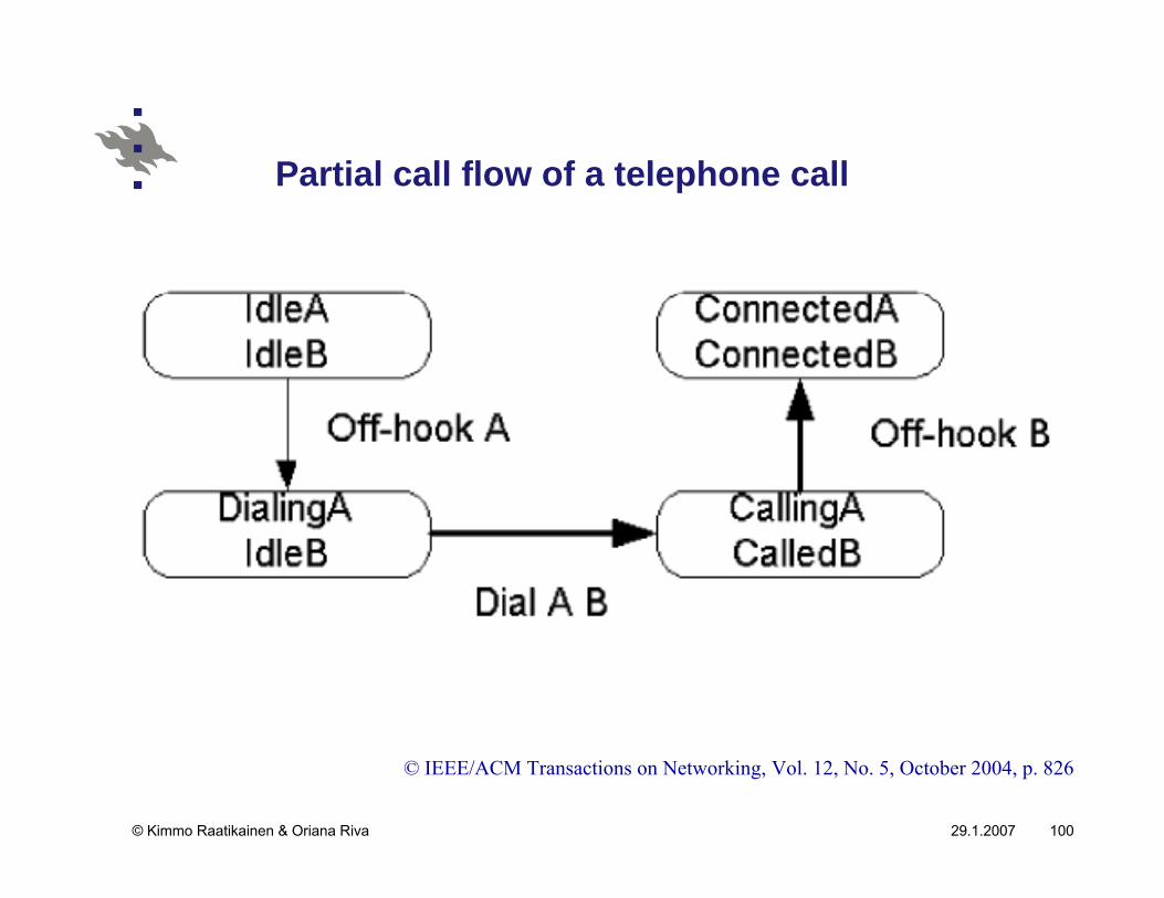
A key idea in developing the test cases is that interoperability errors will be introduced only when the gateways are actually talking to each other about a call
we can ignore local activities involved in the protocol (“white”
transitions)
A white transition is purely local and is involved with only one gateway.
A black transition involves both gateways.
29.1.2007© Kimmo Raatikainen & Oriana Riva 100
Partial call flow of a telephone call
© IEEE/ACM Transactions on Networking, Vol. 12, No. 5, October 2004, p. 826
29.1.2007© Kimmo Raatikainen & Oriana Riva 101
Objectives of interoperability testing
Based on our information about A, we want to construct a set of non redundant tests such that all the interoperations of A with B are tested.
Our goals are:1. Completeness: all the interoperations between the two
systems are tested; and
2. Non-redundancy: all the redundant tests are removed to
minimize the total number of tests

29.1.2007© Kimmo Raatikainen & Oriana Riva 102
An “Exhaustive” Test Set …
To trigger all the interoperations between A and B ideally,we want to include all the possible tests
all the paths from the initial configuration
In general, there are infinitely many such paths.
From the practical experiences in testing, exercising a cycle multiple times has the same coverage for interoperability testing as exercising it once.
29.1.2007© Kimmo Raatikainen & Oriana Riva 103
… An “Exhaustive” Test Set …
Testing a complex cycle (with repeated nodes) is the same as testing each of its simple cycles (without repeated nodes)
We only need to test each simple cycle once for the interoperability testing.
Each path consists of an acyclic path with zero or more simple cycles attached to it
A set of paths that contains all the acyclic paths, on some of which all the simple cycles are attached, has the same coverage as all the paths.
29.1.2007© Kimmo Raatikainen & Oriana Riva 104
… An “Exhaustive” Test Set
In a directed graph, there is a finite number of acyclic paths and a finite number of simple cycles.
The number of such paths is finite, and they consist of a test set with a complete coverage.
29.1.2007© Kimmo Raatikainen & Oriana Riva 105
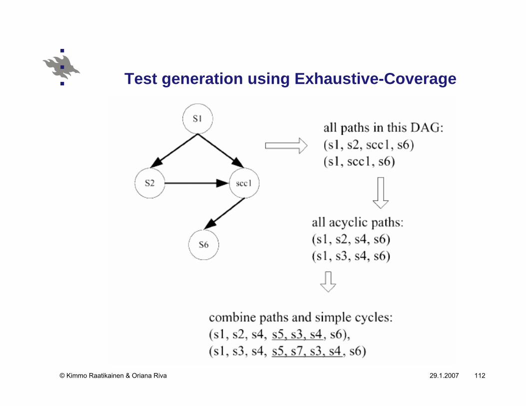
Three steps to generate an exhaustive test set
1. Generate all possible acyclic paths, i.e., paths without any repeated vertices.
2. Generate all possible simple cycles, i.e., cycles that do not contain any smaller cycles.
3. “Combine” the paths (from step 1) and simple cycles(from step 2) to generate the final set of paths.
29.1.2007© Kimmo Raatikainen & Oriana Riva 106
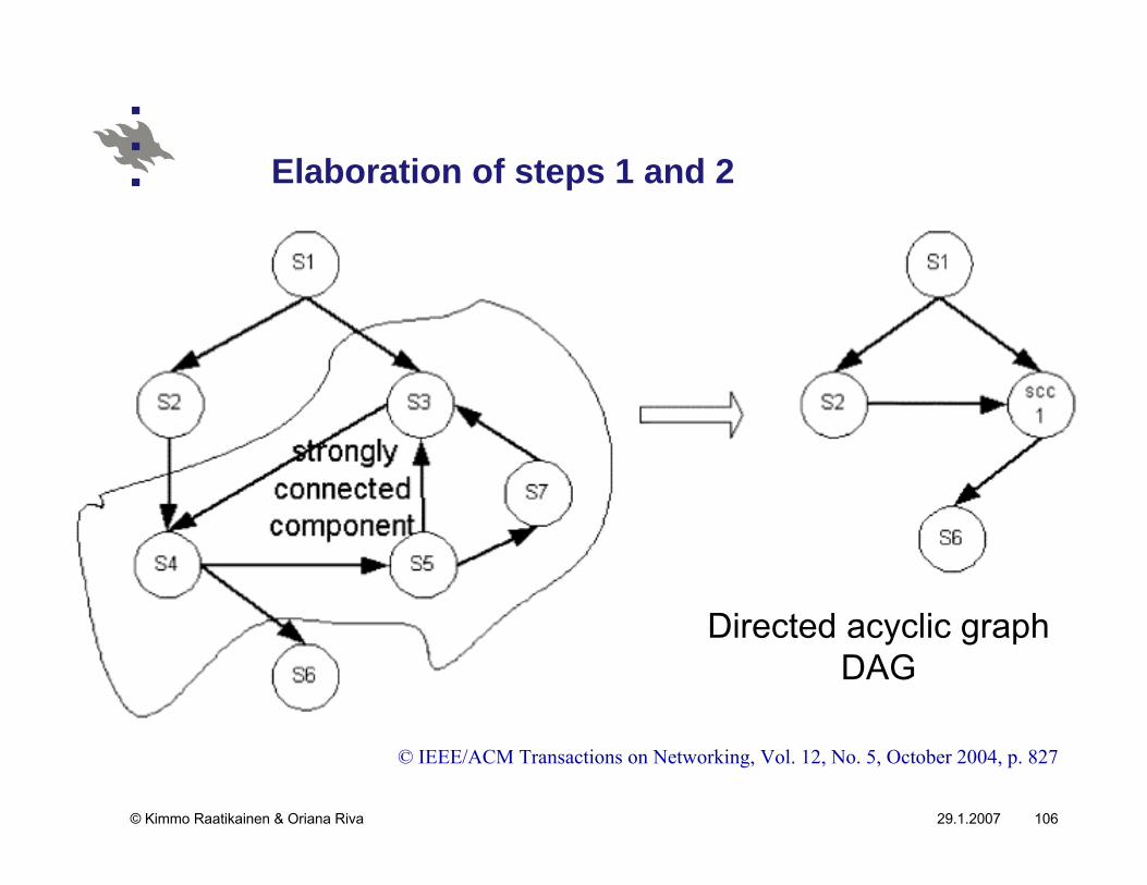
Elaboration of steps 1 and 2
© IEEE/ACM Transactions on Networking, Vol. 12, No. 5, October 2004, p. 827
Directed acyclic graphDAG
29.1.2007© Kimmo Raatikainen & Oriana Riva 107
Next-transition-tree …
This data structure can be defined for any graph, but in our case, the graph will always be an SCC.
For any node v, the next-transition-tree T(v) stores all acyclic paths from v to other vertices in its SCC.
The tree has v as its root.
The children of v are all the nodes in its SCC that have a direct edge from v.

29.1.2007© Kimmo Raatikainen & Oriana Riva 108
… Next-transition-tree
In general, the children of any node u are all the nodes in its SCC that have a direct edge from node u.
If a child node has appeared on the path from the root node v to u, then it is not included in the tree.
Note though that a node may appear multiple times in this tree but not on a tree path.
29.1.2007© Kimmo Raatikainen & Oriana Riva 109
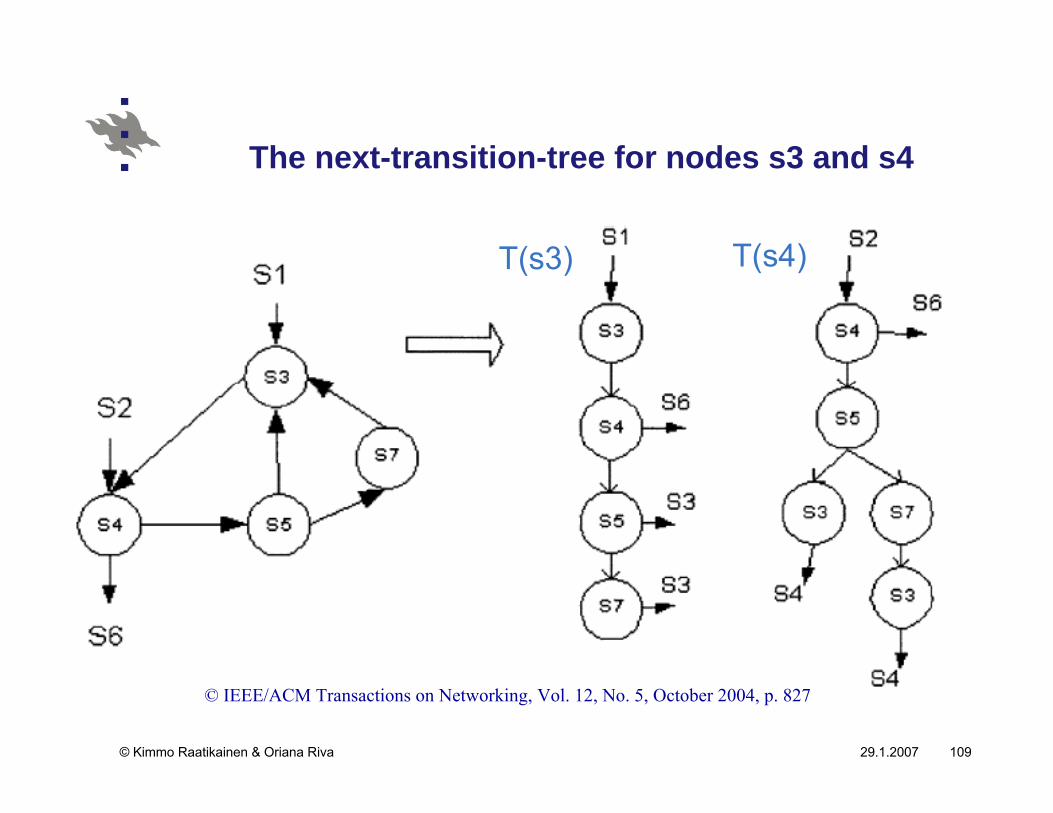
The next-transition-tree for nodes s3 and s4
© IEEE/ACM Transactions on Networking, Vol. 12, No. 5, October 2004, p. 827
T(s3) T(s4)
29.1.2007© Kimmo Raatikainen & Oriana Riva 110
Generating all acyclic paths and simple cycles within an SCC
Let T(v) be the next-transition-tree of node in an SCC.
We can easily obtain all the acyclic paths from v and all the simple cycles containing v.
It is based on the following lemma:For a next-transition-tree from node v, T(v), each tree path
from v to a node u is an acyclic path in the SCC.
Conversely, for each acyclic path from v to u in the SCC, there
is an identical tree path from v to a node u in T(v). Furthermore, all the tree paths in T(v) are distinct.

29.1.2007© Kimmo Raatikainen & Oriana Riva 111
Acyclic paths and simple cycles within an SCC
© IEEE/ACM Transactions on Networking,Vol. 12, No. 5, October 2004, p. 828
29.1.2007© Kimmo Raatikainen & Oriana Riva 112
Test generation using Exhaustive-Coverage
29.1.2007© Kimmo Raatikainen & Oriana Riva 113
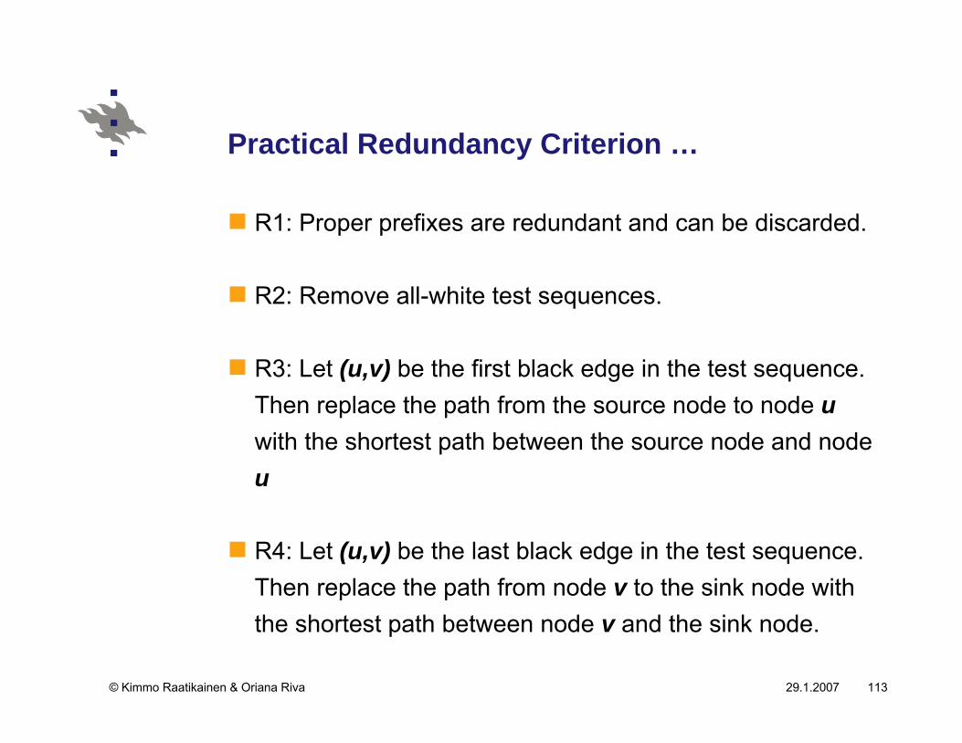
Practical Redundancy Criterion …
R1: Proper prefixes are redundant and can be discarded.
R2: Remove all-white test sequences.
R3: Let (u,v) be the first black edge in the test sequence. Then replace the path from the source node to node uwith the shortest path between the source node and node u
R4: Let (u,v) be the last black edge in the test sequence. Then replace the path from node v to the sink node with the shortest path between node v and the sink node.
29.1.2007© Kimmo Raatikainen & Oriana Riva 114
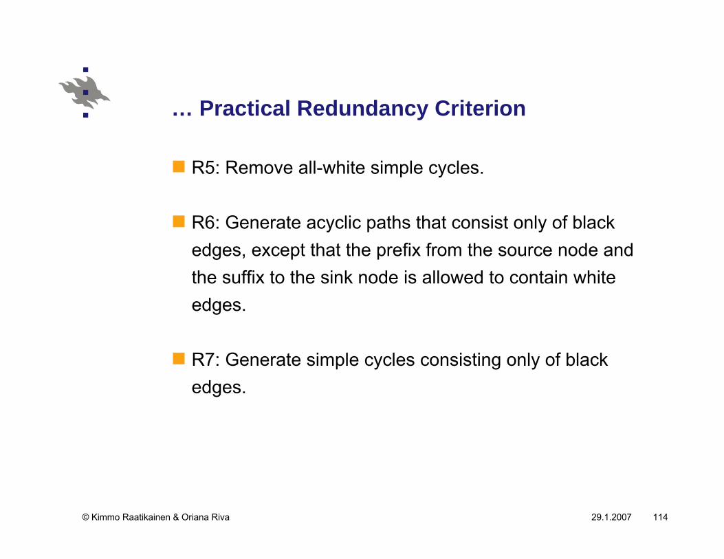
… Practical Redundancy Criterion
R5: Remove all-white simple cycles.
R6: Generate acyclic paths that consist only of black edges, except that the prefix from the source node and the suffix to the sink node is allowed to contain white edges.
R7: Generate simple cycles consisting only of black edges.
29.1.2007© Kimmo Raatikainen & Oriana Riva 115
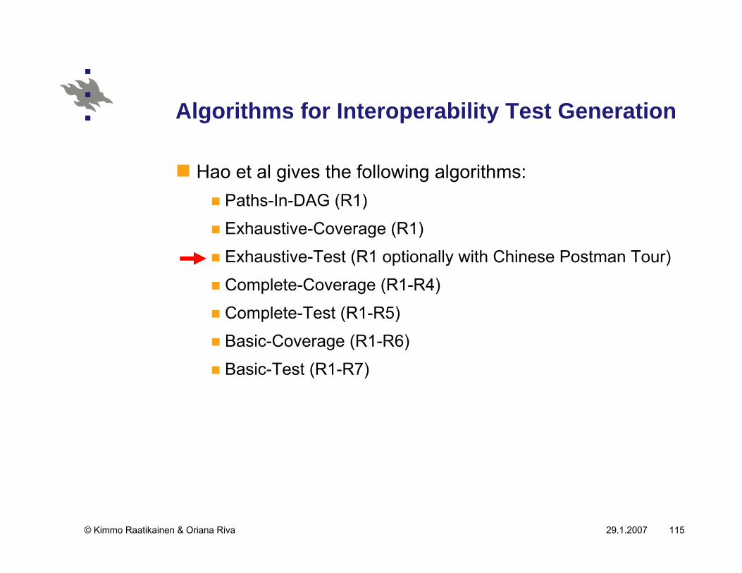
Algorithms for Interoperability Test Generation
Hao et al gives the following algorithms:Paths-In-DAG (R1)
Exhaustive-Coverage (R1)
Exhaustive-Test (R1 optionally with Chinese Postman Tour)
Complete-Coverage (R1-R4)
Complete-Test (R1-R5)
Basic-Coverage (R1-R6)
Basic-Test (R1-R7)
29.1.2007© Kimmo Raatikainen & Oriana Riva 116
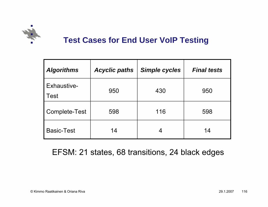
Test Cases for End User VoIP Testing
14414Basic-Test
598116598Complete-Test
950430950Exhaustive-
Test
Final testsSimple cyclesAcyclic pathsAlgorithms
EFSM: 21 states, 68 transitions, 24 black edges
29.1.2007© Kimmo Raatikainen & Oriana Riva 117
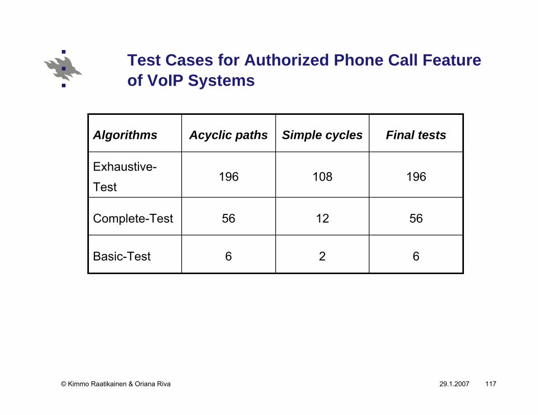
Test Cases for Authorized Phone Call Feature of VoIP Systems
626Basic-Test
561256Complete-Test
196108196Exhaustive-
Test
Final testsSimple cyclesAcyclic pathsAlgorithms
29.1.2007© Kimmo Raatikainen & Oriana Riva 118
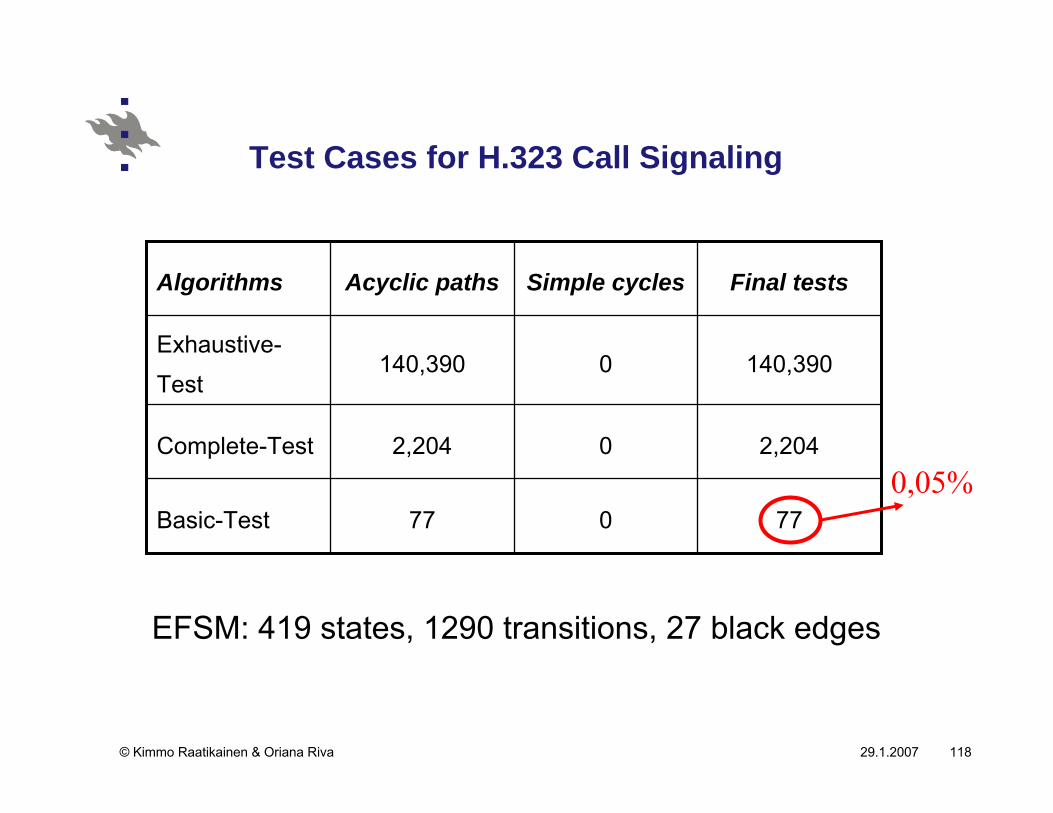
Test Cases for H.323 Call Signaling
77077Basic-Test
2,20402,204Complete-Test
140,3900140,390Exhaustive-
Test
Final testsSimple cyclesAcyclic pathsAlgorithms
EFSM: 419 states, 1290 transitions, 27 black edges
0,05%
29.1.2007© Kimmo Raatikainen & Oriana Riva 119
Conclusions …
Heterogeneity is one of the prominent features of networking systems, and interoperability is ubiquitous and has become a major hurdle for system reliability and quality of service.
Interoperability testing is indispensable for the integration of reactive systems.
Conventional conformance testing techniques do not apply
We want to test the system interfaces but not to check
implementations versus specifications.
29.1.2007© Kimmo Raatikainen & Oriana Riva 120
… Conclusions
While fully recognized by the industry, integrated system interoperability testing provides a challenge and opportunities for researchers to study the essence of the problem and to invent novel technique for system interoperability testing and for improving the reliability of the integrated systems.

29.1.2007© Kimmo Raatikainen & Oriana Riva 121
Testing SDL
29.1.2007© Kimmo Raatikainen & Oriana Riva 122
Testing methods for SDL systems
Testing methods for SDL systems can be classified into two main groups:
those that intent the totally automated test generation from
the SDL systems specification and
those that provide interactive test generation methods

29.1.2007© Kimmo Raatikainen & Oriana Riva 123
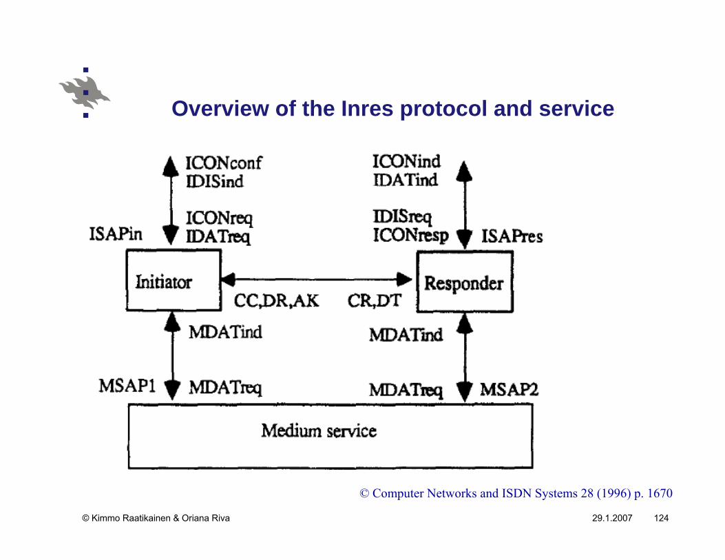
Case study: Inres protocol
The Inres (Initiator-Responder) protocol is connection-oriented and asymmetric.
The initiator establishes a connection and sends data.
The responder accepts and releases connections, and receives data.
29.1.2007© Kimmo Raatikainen & Oriana Riva 124
Overview of the Inres protocol and service
© Computer Networks and ISDN Systems 28 (1996) p. 1670
29.1.2007© Kimmo Raatikainen & Oriana Riva 125
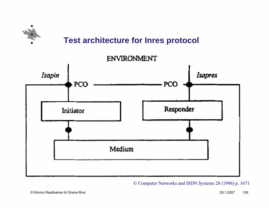
Test architecture
The test architecture is a description of the environment in which the IUT (Implementation Under test) is tested.
There are two possible test architectures for the Inresprotocol.1. If conformance testing for the three blocks of initiator,
medium and responder is requested, the PCOs (Points of Control and Observation) are located at the Isapin and Isapres points, where available PCOs are located directly above the IUT.
2. If conformance testing for the two blocks of initiator and medium is requested, the PCOs are located at the Isapinand at the interaction point between the responder and the medium block.
29.1.2007© Kimmo Raatikainen & Oriana Riva 126
Test architecture for Inres protocol
© Computer Networks and ISDN Systems 28 (1996) p. 1671
29.1.2007© Kimmo Raatikainen & Oriana Riva 127
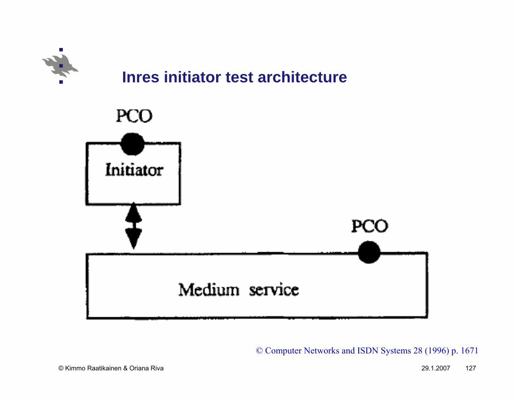
Inres initiator test architecture
© Computer Networks and ISDN Systems 28 (1996) p. 1671
29.1.2007© Kimmo Raatikainen & Oriana Riva 128
Automated test generation methods
Some of the automated test generation methods derive tests directly from the SDL specification.
Others consist of transforming the SDL specification into a model written in another formalism, from which tests are generated.
input/output finite state machines (I/O FSMs) are quite
popular as an intermediate model for test generation.
29.1.2007© Kimmo Raatikainen & Oriana Riva 129
Verification of the uniqueness of UIOs
The validity of any method based on UIOs is based on the fact that the UIOs are unique both in the specification and in the implementation.
Before applying any method based on these concepts and in order to improve the coverage of faults, it is necessary to verify the uniqueness of the identification of each state.
This procedure insures that each state in the implementation has an identification and that it is unique
not accepted by any other state in the implementation
29.1.2007© Kimmo Raatikainen & Oriana Riva 130
Conformance
Since the implementation is tested as a black box, the strongest conformance relation that can be tested is trace equivalence:
two I/O FSMs are trace equivalent if the two cannot be
distinguished by any sequence of inputs.
To prove trace equivalence it suffices to show that(a) there is a set of implementation states {p1,p2,…, pn}
respectively isomorphic to the specification states (s1,s2,...,
sn), and
(b) every transition in the specification has a corresponding
isomorphic transition in the implementation.
29.1.2007© Kimmo Raatikainen & Oriana Riva 131
Assumptions for test generation
The purpose of test generation is to produce a sequence of inputs (and corresponding outputs), called a test sequence, which can be applied to an implementation to verify that it correctly implements the specification.There is a number of necessary assumptions that must be made in order to make the experiment possible:1. the I/O FSM specification is strongly connected, so that all
states can be visited;2. the I/O FSM specification does not have strongly
equivalent states (it is minimized);3. the I/O FSM specification is deterministic and fully
specified; and4. the I/O FSM implementation has no more states than the
I/O FSM specification.
29.1.2007© Kimmo Raatikainen & Oriana Riva 132
External and internal events …
To perform tests on the SDL specifications using the following method, the concept of internal event, denoted by i, is introduced.
In the generation of global I/O FSMs from the reachable state graph, the external events having interactions with the PCOs are separated from the internal events having no direct interaction with the PCOs.
The internal event is a hidden event between the two PCOs and is not visible.
29.1.2007© Kimmo Raatikainen & Oriana Riva 133
… External and internal events
Depending on the location of the PCO, distinct global I/O FSMs containing different internal events can be obtained.
By applying a bisimulation reduction algorithm to the global I/O FSM, these internal events are eliminated and a reference I/O FSM with a small number of states is obtained.
29.1.2007© Kimmo Raatikainen & Oriana Riva 134
Test sequence generation from the SDL specification …
Step 1: A state transition graph is generated. From the state transition graph obtained and the data for the PC0 that interact with the SDL environment, a global I/O FSM is generated that includes external events and internal events.
29.1.2007© Kimmo Raatikainen & Oriana Riva 135
… Test sequence generation from the SDL specification …
Step 2: The global I/O FSM is transformed into the reference I/O FSM. In this step, the transitions that are labelled by internal events (for both the input and output events) and the states between these transitions are eliminated by application of a reduction algorithm. However, we maintain those transitions that have an internal event (as input or output) and an observable event (as input or output). The preserved internal actions will be renamed by “null”.
29.1.2007© Kimmo Raatikainen & Oriana Riva 136
… Test sequence generation from the SDL specification …
Step 3: Some cases of nondeterministic I/O FSMs are transformed into deterministic FSM using a determinization algorithm. In this step, we also transform the I/O FSMs into fully specified I/O FSMs by adding to each state a looping transition having as an input the non-specified input and “null” as an output. Note that this transformation respects the semantics of SDL.
Step 4: The minimization algorithm to eliminate strongly equivalent states is applied.
29.1.2007© Kimmo Raatikainen & Oriana Riva 137
… Test sequence generation from the SDL specification …
Step 5: The strong connectivity of the reference I/O FSM is verified.
Step 6: The UIO sequences are generated for each state.
Step 7: The sequence of tests for verifying the uniqueness of the identification is generated.
29.1.2007© Kimmo Raatikainen & Oriana Riva 138
… Test sequence generation from the SDL specification
Step 8: A non-optimized test sequence is then generated, which tests each transition in the reference I/O FSM starting from the initial state. An optimal test sequence can also be obtained, which is a minimum cost tour for the reference I/O FSM.
Optimization can be obtained using UIO sequences, the
Chinese postman tour or multiple UIOs and overlapping.