Protector Series Installation Guidelines · RD048 - 48 kW 60 Hz (Single Phase Only) RD050 - 50 kW...
48
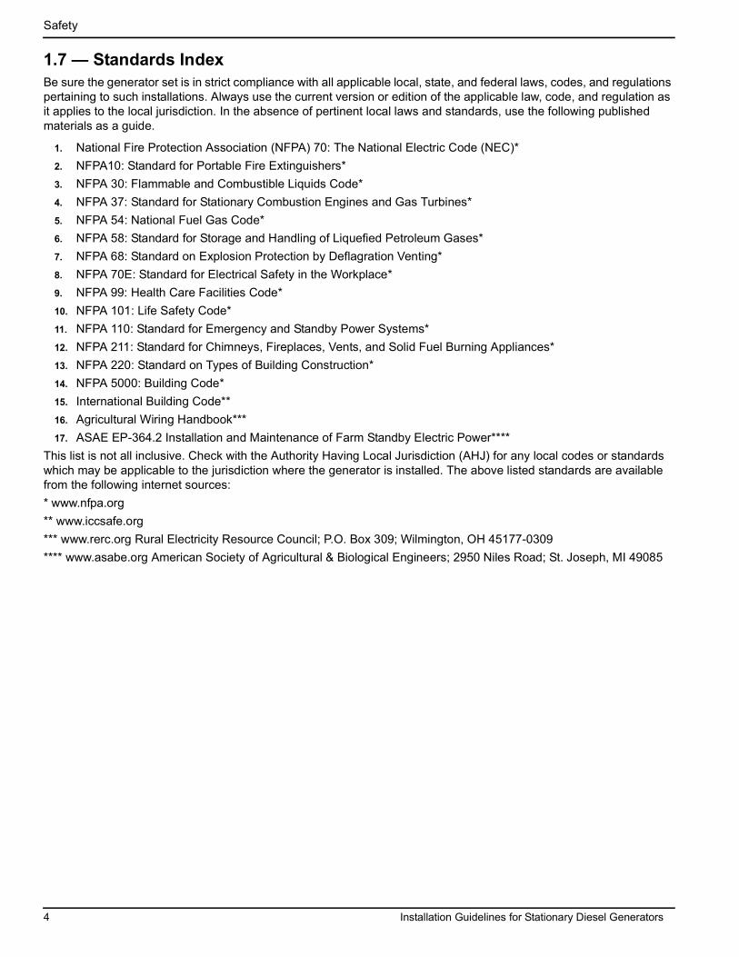
Installation Guidelines For Stationary Diesel Generators Residential and Commercial This manual should remain with the unit. This manual must be used in conjunction with the appropriate owner’s manual. NOT INTENDED FOR USE IN CRITICAL LIFE SUPPORT APPLICATIONS. ONLY QUALIFIED ELECTRICIANS OR CONTRACTORS SHOULD ATTEMPT INSTALLATION! DEADLY EXHAUST FUMES! OUTDOOR INSTALLATION ONLY! Protector™ Series Model RD015 - 15 kW 60 Hz RD020 - 20 kW 60 Hz RD030 - 30 kW 60 Hz RD048 - 48 kW 60 Hz (Single Phase Only) RD050 - 50 kW 60 Hz (Three Phase Only) 0066780 - 30 kW 60 Hz
Transcript of Protector Series Installation Guidelines · RD048 - 48 kW 60 Hz (Single Phase Only) RD050 - 50 kW...
Installation GuidelinesFor
Stationary Diesel GeneratorsResidential and Commercial
This manual should remain with the unit.
This manual must be used in conjunction with the appropriate owner’s manual.
NOT INTENDED FOR USE IN CRITICAL LIFE SUPPORT APPLICATIONS.
ONLY QUALIFIED ELECTRICIANS OR CONTRACTORS SHOULD ATTEMPT INSTALLATION!
DEADLY EXHAUST FUMES! OUTDOOR INSTALLATION ONLY!
Protector™ Series
ModelRD015 - 15 kW 60 HzRD020 - 20 kW 60 HzRD030 - 30 kW 60 HzRD048 - 48 kW 60 Hz (Single Phase Only)
RD050 - 50 kW 60 Hz (Three Phase Only)
0066780 - 30 kW 60 Hz

ii Installation Guidelines for Stationary Diesel Generators
ForwardPurpose and Scope of This ManualREAD THIS MANUAL THOROUGHLY. This manual has been prepared to familiarize personnel involved with the installation of generator sets with the manufacturer’s installation requirements. Information and instructions contained herein are not intended to replace or supersede, local, state, or national safety, electrical, and building codes pertaining to such installations. Applicable laws, codes, and standards must always take precedence over the recommendations contained herein. Always check with the local Authority Having Jurisdiction (AHJ) for the codes or standards that apply.Only authorized dealers or qualified, competent installation contractors or electricians thoroughly familiar with applica-ble codes, standards, and regulations should install this standby electric power system. The installation must be in strict compliance with all codes, standards, and regulations. Start-up procedures must be performed by an Authorized Gen-erac Service Dealer.It is not intended that this manual be used by any unqualified person for the purpose of installing a generator set. Instal-lation, inspection, and testing of the system should be attempted only by competent, qualified electricians or installation contractors who are familiar with the equipment and with all installation codes and requirements.It would be impossible to provide detailed coverage of every installation configuration. For this reason, much of the information contained in this manual is general in nature. Illustrations of typical installations are not intended to serve as detailed installation plans. Always have the drawings and manuals for the specific unit being installed before begin-ning the installation.The information in this manual can be used in the planning and design process phase of selecting and purchasing a generator set for a standby power application.
Sources of InformationInstallation information and recommendations contained herein are derived from the following sources:
• Knowledgeable engineers, service technicians, and service representatives.• The National Electric Code (NEC).• National Fire Protection Association (NFPA) codes and standards.• Other sources as listed in Subsection 1.7.• Various manufacturing standards and best practices.
If this generator is used to power electrical load circuits normally powered by a utility power source, it is required by code to install a transfer switch. The transfer switch must effectively isolate the electric system from the utility distribution system when the generator is operating. Failure to isolate an electrical system by such means may result in damage to the generator and may also result in injury or even death to utility power workers due to backfeed of electrical energy.
If an open bottom is used, the engine-generator is to be installed over non-combustible materials and should be located such that combustible materials are not capable of accumulating under the generator set.
After the system has been installed, do nothing that might render the installation in non-compliance with such codes, standards, and regulations.
Every effort was made to ensure the information in this manual was both accurate and current at the time it was released. However, the manufacturer reserves the right to change, alter, or otherwise improve this product at any time and without prior notice.
Installation Guidelines for Stationary Diesel Generators iii
Section 1 Safety1.1 Introduction .......................................................................................................................... 11.2 Safety Rules .......................................................................................................................... 11.3 General Hazards ...................................................................................................................21.4 Electrical Hazards ................................................................................................................31.5 Fire Hazards ..........................................................................................................................31.6 Explosion Hazards ............................................................................................................... 31.7 Standards Index ...................................................................................................................4
Section 2 Installation Planning2.1 Protector Diesel Pre-Order Checklist ................................................................................. 52.2 Unit Drawings ....................................................................................................................... 7
2.2.1 Installation Drawings ................................................................................................................................. 72.2.2 Wiring Diagrams ......................................................................................................................................... 7
2.3 Receiving ..............................................................................................................................72.3.1 Receiving and Unpacking .......................................................................................................................... 72.3.2 Inspection .................................................................................................................................................... 7
2.4 Storage Before Installation ..................................................................................................82.4.1 Long Term Storage ..................................................................................................................................... 82.4.2 Short Term Storage .................................................................................................................................... 8
2.5 Lifting .................................................................................................................................... 82.6 Generator Location ..............................................................................................................8
2.6.1 General Location Guidelines ..................................................................................................................... 92.6.2 Weather Considerations ............................................................................................................................ 9
2.7 Accessories .......................................................................................................................... 9
Section 3 Foundations & Mounting3.1 Generator Foundations ......................................................................................................11
3.1.1 Concrete Pad ............................................................................................................................................ 113.1.2 Dimensions ............................................................................................................................................... 113.1.3 Unit Clearance .......................................................................................................................................... 113.1.4 Stub Up Area ............................................................................................................................................. 11
3.2 Mounting .............................................................................................................................123.2.1 Fixed Foundation ...................................................................................................................................... 123.2.2 Connections .............................................................................................................................................. 12
Section 4 Ventilation System4.1 General ................................................................................................................................13
Table of Contents

Table of Contents
iv Installation Guidelines for Stationary Diesel Generators
4.2 Outdoor Installation Only ..................................................................................................134.2.1 Clearance ................................................................................................................................................... 13
Section 5 Diesel Fuel Systems5.1 General Information ...........................................................................................................155.2 Diesel Fuel Base Tank ........................................................................................................155.3 Diesel Fuel Recommendations .........................................................................................16
5.3.1 Fuel Maintenance ...................................................................................................................................... 16
Section 6 Electrical System6.1 General Information ...........................................................................................................176.2 Remove Rear Panel and Stub Up Cover ...........................................................................176.3 Wiring Installation Safety ...................................................................................................176.4 General Wiring Requirements ...........................................................................................176.5 High Voltage Connections .................................................................................................176.6 Control Wiring Connections ..............................................................................................206.7 Optional Accessory Power ................................................................................................226.8 Install Stub Up Cover and Rear Panel ..............................................................................226.9 Transfer Switch Location ...................................................................................................226.10 Battery ...............................................................................................................................23
6.10.1 General Cautions .................................................................................................................................... 236.10.2 Battery Size ............................................................................................................................................. 236.10.3 Battery Replacement .............................................................................................................................. 23
6.11 Operational Checks ..........................................................................................................256.11.1 Self Test ................................................................................................................................................... 256.11.2 Check Manual Transfer Switch Operation ............................................................................................ 266.11.3 Electrical Checks .................................................................................................................................... 266.11.4 Test Generator Under Load ................................................................................................................... 266.11.5 Check Automatic Operation .................................................................................................................. 27
6.12 Installation Summary .......................................................................................................27
Section 7 Installation Checklists7.1 Safety Checklist ..................................................................................................................297.2 Installation Planning Checklist .........................................................................................297.3 Foundations & Mounting Checklist ..................................................................................307.4 Ventilation System Checklist ............................................................................................307.5 Diesel Fuel System Checklist ............................................................................................317.6 Electrical System Checklist ...............................................................................................31

Table of Contents
Installation Guidelines for Stationary Diesel Generators v
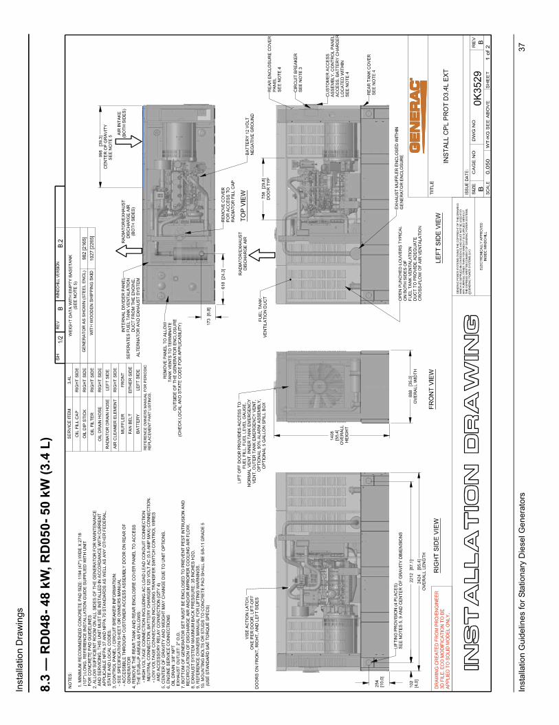
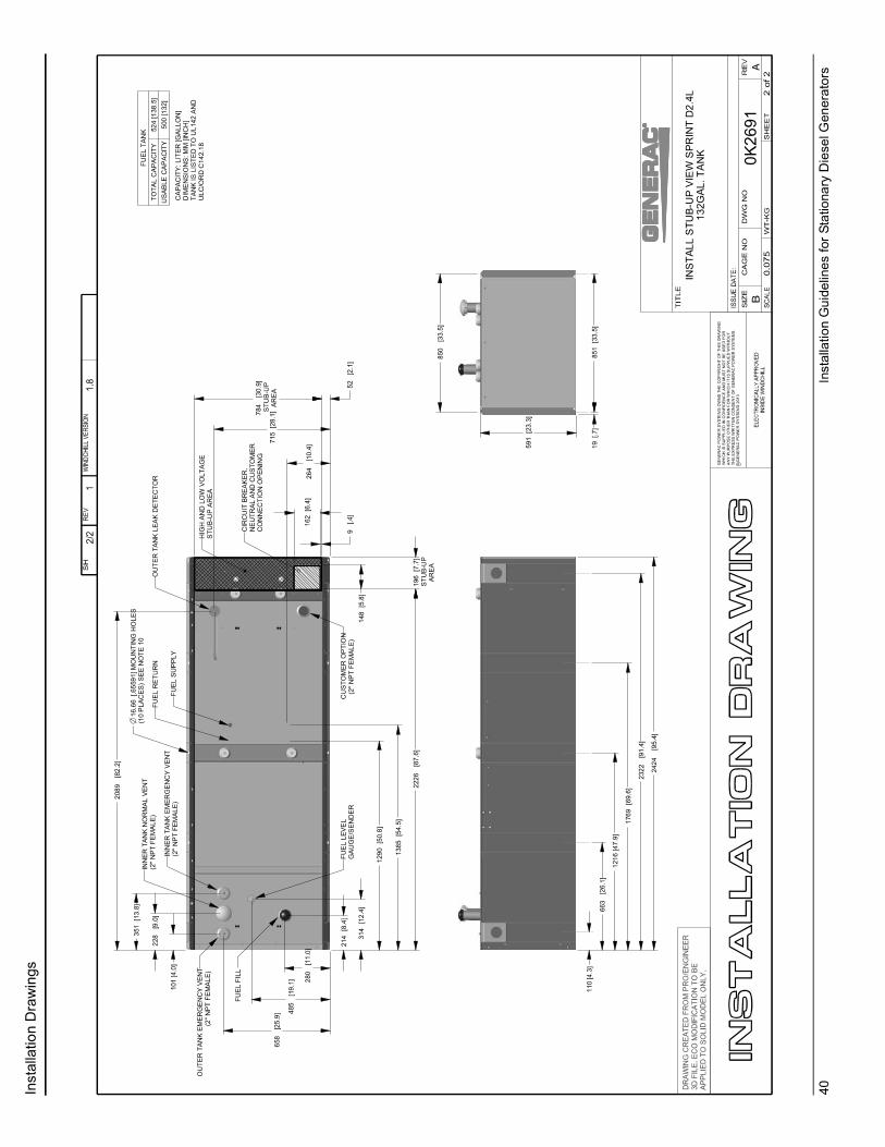
Section 8 Installation Drawings8.1 RD015- 15 kW, RD020- 20 kW (2.3 L) ................................................................................ 338.2 RD030- 30 kW (2.4 L) .......................................................................................................... 358.3 RD048- 48 kW, RD050- 50 kW (3.4 L) ................................................................................ 378.4 0066780- 30 kW (2.4 L) ....................................................................................................... 39

Table of Contents
vi Installation Guidelines for Stationary Diesel Generators
This page intentionally left blank.

Installation Guidelines for Stationary Diesel Generators 1
Section 1 Safety1.1 — IntroductionRead this manual thoroughly. If any portion is not understood, contact the nearest Authorized Generac Service Dealer for clarification. The manufacturer also requires having an Authorized Service Dealer oversee the installation of any standby generator set. Trained/qualified service technicians familiar with the control systems and available options have full access to drawings, publications, and other information required for a successful installation.
1.2 — Safety RulesThroughout this publication, and on tags and decals affixed to the generator, DANGER, WARNING, CAUTION, and NOTE boxes are used to alert personnel to special instructions about a particular operation that may be hazardous if performed incorrectly or carelessly. Observe them carefully. They indicate:
Indicates a hazardous situation or action that, if not avoided, will result in death or serious injury.
Indicates a hazardous situation or action that, if not avoided, could result in death or seri-ous injury.
Indicates a hazardous situation or action that, if not avoided, could result in minor or mod-erate injury.NOTE: Notes provide additional information important to a procedure or component.
These safety warnings cannot eliminate the hazards they indicate. Observing safety precautions and strict compliance with the special instructions while performing the action or service are essential to preventing accidents.Four commonly used safety symbols accompany DANGER, WARNING, and CAUTION boxes and the type of informa-tion each indicates:
This symbol points out important safety information that, if not followed, could endanger personnel and/or property.
This symbol represents the potential for an Explosion Hazard.
This symbol represents the potential for a Fire Hazard.
This symbol represents the potential for an Electrical Shock Hazard.
SAVE THESE INSTRUCTIONS. This manual contains important instructions that should be followed during installation of the generator set and batteries. The manufacturer suggests that these safety rules be copied and posted in potential hazard areas. Safety should be stressed to all installers, operators, potential operators, and service and repair technicians for this equipment.

Safety
2 Installation Guidelines for Stationary Diesel Generators
The manufacturer cannot anticipate every possible circumstance that might involve a hazard. The warnings in this manual, and on tags and decals affixed to the unit, are not all-inclusive. If using a procedure, work method, or operating technique the manufacturer does not specifically recommend, ensure that it is safe for others. Also make sure the pro-cedure, work method, or operating technique used does not render the generator unsafe.
• Despite the safe design of this generator, operating this equipment imprudently, neglecting its maintenance, or being careless can cause possible injury or death. Permit only responsible and capable persons to install, oper-ate, and maintain this equipment.
• Parts of the generator are rotating and/or hot during operation. Exercise care near running generators.• If this generator is used to power electrical load circuits normally powered by a utility power source, install a
transfer switch. The transfer switch must effectively isolate the electrical system from the utility distribution sys-tem when the generator is operating. Failure to isolate an electrical system by such means will result in damage to the generator and also may result in injury or death to utility power workers due to backfeed of electrical energy.
Generators produce potentially lethal voltages. Ensure all steps are taken to make the genera-tor safe before operation or service.
1.3 — General Hazards
• For safety reasons, the manufacturer recommends that this equipment be installed, serviced, and repaired by an Authorized Service Dealer or other competent, qualified electrician or installation technician who is familiar with all applicable codes, standards, and regulations.
• Ensure that the generator is installed, operated, and serviced in accordance with the manufacturer’s instructions and recommendations. Following installation, do nothing that might render the unit unsafe or in noncompliance.
• The engine exhaust fumes contain carbon monoxide, which can be DEADLY. If breathed in sufficient concentra-tions, carbon monoxide can cause unconsciousness or even death. For this reason, adequate ventilation must be provided. Exhaust gases must be piped safely away from any building or enclosure that houses the generator to an area where people, animals, etc. will not be harmed.
• Keep hands, feet, clothing, etc. away from drive belts, fans, and other moving or hot parts. Never remove any drive belt or fan guard while the unit is operating. Ensure that all guards, covers, and protective devices removed during maintenance or service are reinstalled.
• Adequate, unobstructed flow of cooling and ventilating air is critical to prevent buildup of explosive gases and to ensure correct generator operation. Do not alter the installation or permit even partial blockage of ventilation pro-visions, as this can affect safe operation of the generator.
• Keep the area around the generator clean and uncluttered. Remove any materials that could become hazardous.• When working on this equipment, remain alert at all times. Never work on the equipment when physically or men-
tally fatigued.• Inspect the generator regularly, and promptly repair or replace any worn or damaged components using only fac-
tory approved parts and procedures.• Before performing any maintenance on the generator, always disconnect the battery cables to prevent accidental
startup. Disconnect the cable from the battery post indicated by a NEGATIVE, NEG, or (�) first, then remove the POSITIVE, POS, or (+) cable. When reconnecting the cables, connect the POSITIVE cable first, the NEGATIVE cable last.
• Never use the generator or any of its parts as a step. Stepping on the unit can stress and break parts, and may result in exhaust, fuel, oil or coolant leaks.

Safety
Installation Guidelines for Stationary Diesel Generators 3
1.4 — Electrical Hazards
• All generators produce dangerous electrical voltages and can cause fatal electrical shock. Utility power delivers extremely high and dangerous voltages to the transfer switch as well as the generator when it is in operation. Avoid contact with bare wires, terminals and other connections. Ensure all covers, guards, and barriers are in place, and that they are properly secured and/or locked before operation. If work must be done around an oper-ating unit, stand on an insulated, dry surface to reduce potential shock hazard.
• Do not handle any kind of electrical device while standing in water, while barefoot, or while hands or feet are wet. DANGEROUS ELECTRICAL SHOCK MAY RESULT.
• If it is necessary to stand on metal or concrete while installing, operating, servicing, or repairing this equipment, lay down a dry wooden platform and cover with insulated mats before beginning.
• Verify that the generator is properly grounded.• Wire gauge sizes of electrical wiring, cables, and cord sets must be adequate to handle the maximum electrical
current (ampacity) to which it will be subjected.• Before installing or servicing equipment, verify that all power voltage supplies are positively turned off at their
sources. Failure to do so can result in hazardous and possibly fatal electrical shock.• Connecting this unit to an electrical system normally supplied by an electric utility is by means of a transfer switch
so as to isolate the generator electric system from the electric utility distribution system when the generator is operating. Failure to isolate the two electric system power sources from each other by such means will result in damage to the generator and may also result in injury or death to utility power workers due to backfeed of electri-cal energy.
• Generators installed with an automatic transfer switch will crank and start automatically when NORMAL (UTIL-ITY) source voltage is removed or is below an acceptable preset level. To prevent automatic startup and possible injury, disable the automatic start circuit (battery cables, etc.) before working on or around the unit. Place a “DO NOT OPERATE” tag on the generator control panel and on the transfer switch.
• In case of accident caused by electric shock, immediately shut down the source of electrical power. If this is not possible, attempt to free the victim from the live conductor. AVOID DIRECT CONTACT WITH THE VICTIM. Use a nonconducting implement, such as a dry rope or board, to free the victim from the live conductor. If the victim is unconscious, apply first aid and get immediate medical help.
• Do not wear jewelry when working on this equipment. Jewelry can conduct electricity resulting in electric shock, or may get caught in moving parts resulting in injury.
1.5 — Fire Hazards
• Keep a fire extinguisher near the generator at all times. Keep the extinguisher properly charged and be familiar with its use. Direct any questions to the local fire department.
NOTE: DO NOT use any carbon tetra-chloride type fire extinguishers. These fire extinguishers emit toxic fumes and the liquid can damage wiring insulation.
1.6 — Explosion Hazards
• Properly ventilate the room or building housing the generator to prevent buildup of explosive gas.• Do not smoke around the generator. Immediately wipe up any fuel or oil spills. Ensure that no combustible mate-
rials are left in the generator compartment, or on or near the generator, as FIRE or EXPLOSION may result. Keep the area surrounding the generator clean and free of debris.
• All types of fuels are potentially FLAMMABLE and/or EXPLOSIVE and must be handled with care. Inspect the fuel system frequently and correct any leaks immediately. Be sure fuel supply lines are properly installed, purged, and leak tested before placing the generator set into service.
Safety
4 Installation Guidelines for Stationary Diesel Generators
1.7 — Standards IndexBe sure the generator set is in strict compliance with all applicable local, state, and federal laws, codes, and regulations pertaining to such installations. Always use the current version or edition of the applicable law, code, and regulation as it applies to the local jurisdiction. In the absence of pertinent local laws and standards, use the following published materials as a guide.
1. National Fire Protection Association (NFPA) 70: The National Electric Code (NEC)*2. NFPA10: Standard for Portable Fire Extinguishers*3. NFPA 30: Flammable and Combustible Liquids Code*4. NFPA 37: Standard for Stationary Combustion Engines and Gas Turbines*5. NFPA 54: National Fuel Gas Code*6. NFPA 58: Standard for Storage and Handling of Liquefied Petroleum Gases*7. NFPA 68: Standard on Explosion Protection by Deflagration Venting*8. NFPA 70E: Standard for Electrical Safety in the Workplace*9. NFPA 99: Health Care Facilities Code*10. NFPA 101: Life Safety Code*11. NFPA 110: Standard for Emergency and Standby Power Systems*12. NFPA 211: Standard for Chimneys, Fireplaces, Vents, and Solid Fuel Burning Appliances*13. NFPA 220: Standard on Types of Building Construction*14. NFPA 5000: Building Code*15. International Building Code**16. Agricultural Wiring Handbook***17. ASAE EP-364.2 Installation and Maintenance of Farm Standby Electric Power****
This list is not all inclusive. Check with the Authority Having Local Jurisdiction (AHJ) for any local codes or standards which may be applicable to the jurisdiction where the generator is installed. The above listed standards are available from the following internet sources:* www.nfpa.org** www.iccsafe.org*** www.rerc.org Rural Electricity Resource Council; P.O. Box 309; Wilmington, OH 45177-0309**** www.asabe.org American Society of Agricultural & Biological Engineers; 2950 Niles Road; St. Joseph, MI 49085

Installation Guidelines for Stationary Diesel Generators 5
Section 2 Installation Planning2.1 — Protector Diesel Pre-Order Checklist
The local fire marshal has confirmed that the generator must be located a minimum of ________ feet from a house or other structure. NOTE: Generac recommends a minimum clearance of five feet.
The local AHJ has advised me regarding the requirements for electrical and/or building permits, as well as those regulations relating to emissions and fuel storage.
I have been advised of the local requirements for construction of a concrete base pad, and whether anchoring requirements are needed for installation on a flood plain.
I have confirmed with the appropriate authorities that the generator must be located a minimum of ________ feet from a property line.
I have been advised whether the local fire marshal (or other third party) is required to be present at start up.
I have confirmed that the installation site is applicable to optional standby only and does not require an NFPA 110 capable generator.
The local fire marshal has confirmed that I am required to extend the fuel tank vents ________ feet above the surrounding grade.
The local fire marshal has confirmed that local codes require installation of the diesel product safety accessories designated below.
Item Description Part Number Required
Emergency StopSwitch 006510-0
YES
NO
90% Fuel Fill Level Alarm 006504-0
YES
NO

Installation Planning
6 Installation Guidelines for Stationary Diesel Generators
Item Description Part Number Required
Five Gallon Spill Box 006502-0YES
NO
Spill Box Drain Back 006511-0YES
NO
Fuel Fill Drop Tube 006507-0YES
NO
Fuel Tank Support Risers
006505-0 (15 & 20 kW)006506-0 (30 & 50 kW)
YES NO
YES NO
Stainless Steel Fuel Lines
006513-0 (15 & 20 kW)006517-0 (30 kW)006516-0 (50 kW)
YES NO
YES NO
YES NO
Installation Planning
Installation Guidelines for Stationary Diesel Generators 7
2.2 — Unit Drawings
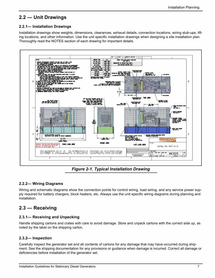
2.2.1— Installation DrawingsInstallation drawings show weights, dimensions, clearances, exhaust details, connection locations, wiring stub-ups, lift-ing locations, and other information. Use the unit specific installation drawings when designing a site installation plan. Thoroughly read the NOTES section of each drawing for important details.
Figure 2-1. Typical Installation Drawing
2.2.2— Wiring DiagramsWiring and schematic diagrams show the connection points for control wiring, load wiring, and any service power sup-ply required for battery chargers, block heaters, etc. Always use the unit specific wiring diagrams during planning and installation.
2.3 — Receiving
2.3.1— Receiving and UnpackingHandle shipping cartons and crates with care to avoid damage. Store and unpack cartons with the correct side up, as noted by the label on the shipping carton.
2.3.2— InspectionCarefully inspect the generator set and all contents of cartons for any damage that may have occurred during ship-ment. See the shipping documentation for any provisions or guidance when damage is incurred. Correct all damage or deficiencies before installation of the generator set.
Installation Planning
8 Installation Guidelines for Stationary Diesel Generators
2.4 — Storage Before Installation
2.4.1— Long Term StorageIf the unit is to be stored (or installed and not started-up) for six months or more, preserve in accordance with the man-ufacturer’s instructions. Contact the local Authorized Service Dealer to obtain the Long Term Preservation and Storage Manual (Part No. 0G4018) and the Preservation Checklist (Part No. 0G4018A).
2.4.2— Short Term StorageIf the unit is to be stored (or installed and not started-up) for less than six months, proceed as follows:
• All units are provided with an enclosure.• Place the unit on a smooth flat surface. Do not leave unit on the shipping pallet, as it leaves the bottom open for
entry of dirt, debris, insects, rodents, etc.• Leave exhaust system openings covered.• Leave plastic plugs in fuel connection points. • Use anti-rodent plugs and other enclosure features to prevent entry of birds, small animals, and foreign objects.
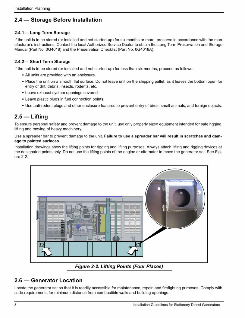
2.5 — LiftingTo ensure personal safety and prevent damage to the unit, use only properly sized equipment intended for safe rigging, lifting and moving of heavy machinery.
Use a spreader bar to prevent damage to the unit. Failure to use a spreader bar will result in scratches and dam-age to painted surfaces. Installation drawings show the lifting points for rigging and lifting purposes. Always attach lifting and rigging devices at the designated points only. Do not use the lifting points of the engine or alternator to move the generator set. See Fig-ure 2-2.
Figure 2-2. Lifting Points (Four Places)
2.6 — Generator LocationLocate the generator set so that it is readily accessible for maintenance, repair, and firefighting purposes. Comply with code requirements for minimum distance from combustible walls and building openings.

Installation Planning
Installation Guidelines for Stationary Diesel Generators 9
2.6.1— General Location GuidelinesConsider the following:
• The supporting structure must be adequate for the generator set and its accessories.• Be sure the site is clean, dry, not subject to flooding, and provided with adequate drainage in the event of heavy
rains.• Be sure the location permits noise and vibration to be effectively isolated.• Verify that the site provides easy access to the generator set for maintenance, repair, and firefighting purposes.• Keep a minimum of five feet of clearance around each side of the generator set to facilitate service or mainte-
nance. • Be sure the location permits engine exhaust gases to be safely evacuated from inhabited or occupied areas.
Consider the direction of prevailing winds to prevent exhaust gases from being carried back to the engine area or to the fresh air intake vents of nearby buildings.
• The site must allow for the provision of an adequate fuel supply. Consider the ease of accessibility for refueling purposes.
• Be sure the location permits sufficient air flow for cooling and ventilation. Consider the proximity of any walls, fences, or other noise abatement or security barriers. Do NOT face the radiator discharge end of the enclosure into the prevailing wind.
• Consider cold weather kit options and accessories for the generator in cold weather locations.• Verify that the unit is securely fastened to the mounting pad to prevent movement caused by vibration.• Verify that all electrical connections have flexible sections to isolate vibration.
NOTE: Failure to comply with the location guidelines can result in damage to the generator or surrounding area and may cause the warranty to be suspended or voided. Extra repair labor or equipment may not be covered under the warranty if service access is difficult or restricted.
2.6.2— Weather ConsiderationsConsider local weather conditions during installation. There are various accessories available to ensure fast, reliable starting and operation regardless of local climatic conditions. Optional cold weather kits make starting of the engine more dependable and reliable.
2.7 — AccessoriesThe following product accessories are available. Contact a Dealer for additional information.
1. Scheduled Maintenance Kit (Part No. 006572-0; 15/20 kW) 8. Emergency Stop Switch (Part No. 006510-0)
2. Scheduled Maintenance Kit (Part No. 006571-0; 30 kW) 9. Touch-Up Paint Kit (Part No. 005704-0)
3. Scheduled Maintenance Kit (Part No. 006570-0; 50 kW) 10. Five Gallon Spill Box (Part No. 006502-0)
4. Cold Weather Kit (Part No. 006560-0: 15/20 kW; Part No. 006559-0: 30 kW; Part No. 006558-0: 50 kW)
11. Fuel Tank Risers (Part No. 006505-0: 15/20 kW; Part No. 006506-0: 30/50 kW)
5. Vent Extension Support Kit (Part No. 006588-0) 12. 90% Fuel Fill Level Alarm (Part No. 006504-0)
6. Fuel Fill Drop Tube (Part No. 006507-0) 13. Spill Box Drain Back (Part No. 006511-0)
7. Lockable Fuel Fill Cap (Part No. 006512-0) 14. Stainless Steel Fuel Lines (Part No. 006513-0:15/20 kW; Part No. 006517-0: 30 kW; Part No. 006516-0: 50 kW)

Installation Planning
10 Installation Guidelines for Stationary Diesel Generators
Figure 2-3. Product Accessories
1. 2.
6.
7. 8.
3.
4.
5.
9. 10.
12. 13. 14.
11.

Installation Guidelines for Stationary Diesel Generators 11
Section 3 Foundations & Mounting3.1 — Generator FoundationsInstall the generator set on a concrete pad or base slab able to support its weight and accessories. A proper foundation is needed to resist dynamic loading and reduce transmitted noise and vibration. The exact composition of the mounting pad must follow standard engineering practices for the required loading and application. Securely fasten the genera-tor set to the foundation using suitable grade, size and style fasteners. Holes are provided in the base tank frame for this purpose.
3.1.1— Concrete PadSeat the concrete pad or base slab on a prepared solid subsurface and use appropriate reinforcing bar or expanded wire mesh. A common specification calls for 2500 psi concrete reinforced with 8 gauge wire mesh or number 6 reinforc-ing bars on 12 inch centers.
3.1.2— DimensionsExtend the concrete pad beyond the frame of the unit at least 12 inches and above the surrounding surface by 6 inches. This provides a mounting surface for fuel line support, as well as space for maintenance and repair.The base pad must be:
• Capable of supporting 125% of the unit wet weight for single unit applications. Wet weight is the dry weight plus the weight of the fuel in the base tank.
• Flat and level to within 1/2 inch.• Capable of withstanding severe torque reactions.
3.1.3— Unit ClearanceVerify that the site provides easy access to the generator set for maintenance, repair, and firefighting purposes. Keep a minimum of five feet of clearance around each side of the generator set to facilitate service or maintenance.
3.1.4— Stub Up AreaFor load conduit, auxiliary power conduit (high voltage), and control wiring conduit (low voltage), see the installation drawings for the location and dimensions of the stub up areas. See Figure 3-1.

Foundations & Mounting
12 Installation Guidelines for Stationary Diesel Generators
Figure 3-1. Typical Installation Drawing Stub Up Detail
3.2 — Mounting
3.2.1— Fixed FoundationUse mounting holes in the base frame to fasten the unit to the foundation. Always use hardware of a suitable grade, size and style.
3.2.2— ConnectionsAll electrical connections must have flexible sections where they connect to the unit to isolate vibration. Properly sup-port and secure all piping before installing the flexible connection.
Installation Guidelines for Stationary Diesel Generators 13
Section 4 Ventilation System4.1 — GeneralAdequate and unobstructed flow of cooling and ventilating air is critical to prevent buildup of explosive gases and to ensure safe generator operation. Do not alter the installation or permit even partial blockage of ventilation provisions. Keep area around the generator clean and uncluttered, and remove any materials that may pose a hazard.
4.2 — Outdoor Installation OnlyThe installation design must ensure that there are no obstructions at any of the air intakes that may impede intake air-flow. The unit is for outdoor installation only.
4.2.1— ClearanceKeep a minimum of five feet of clearance around the unit to facilitate service and maintenance, and to ensure adequate air circulation for air intakes and cooling of exhaust discharges.

Ventilation System
14 Installation Guidelines for Stationary Diesel Generators
This page intentionally left blank.
Installation Guidelines for Stationary Diesel Generators 15
Section 5 Diesel Fuel Systems5.1 — General InformationSince diesel fuels are less volatile than gasoline or gaseous fuels, they are sometimes considered safer. Due to this perception, careless installation practices can occur, which may lead to serious problems with generator set perfor-mance and reliability.Periodically inspect and test the system to ensure all components remain in good working order.
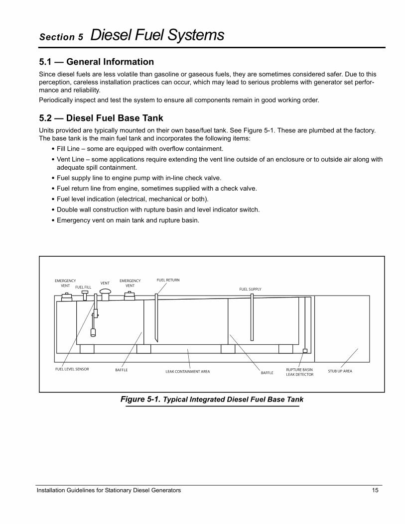
5.2 — Diesel Fuel Base TankUnits provided are typically mounted on their own base/fuel tank. See Figure 5-1. These are plumbed at the factory. The base tank is the main fuel tank and incorporates the following items:
• Fill Line � some are equipped with overflow containment.• Vent Line � some applications require extending the vent line outside of an enclosure or to outside air along with
adequate spill containment.• Fuel supply line to engine pump with in-line check valve.• Fuel return line from engine, sometimes supplied with a check valve.• Fuel level indication (electrical, mechanical or both).• Double wall construction with rupture basin and level indicator switch.• Emergency vent on main tank and rupture basin.
Figure 5-1. Typical Integrated Diesel Fuel Base Tank

Diesel Fuel Systems
16 Installation Guidelines for Stationary Diesel Generators
5.3 — Diesel Fuel RecommendationsIMPORTANT! DO NOT use Home Heating Oil or Bio-Diesel Fuel.
Use No.1D diesel fuel when temperatures are below freezing. Use No. 2D diesel fuel when temperatures are above freezing. Starting October 1, 2010, diesel fuel must also meet the following requirements:
• Sulfur content of 15 parts per million (ppm) maximum.• Maximum Cetane index of 40 or a maximum aromatic content of 35 volume percent.
Allow at least 5 percent of the tank capacity for fuel expansion. DO NOT OVERFILL!
5.3.1— Fuel MaintenanceDiesel fuel must be treated for long term storage. Use approved fuel additive and water abatement material. Test stored fuel every 90 days and add treatment as required. Periodically check and dry abatement as needed.

Installation Guidelines for Stationary Diesel Generators 17
Section 6 Electrical System6.1 — General InformationAll wiring must be properly sized, routed, supported, and connected. All wiring must comply with NEC and local codes.The generator uses Customer Connection Interface (CCI) panels to separate the high voltage and customer control wiring connections. These two panels are clearly labeled. The wiring diagrams for each specific unit show the connec-tion points in their corresponding sections. Terminal boards are clearly labeled and correspond to the same terminal connections shown in the wiring diagrams. Always use the unit specific wiring diagrams when making wiring connec-tions.
6.2 — Remove Rear Panel and Stub Up Cover1. See Figure 6-1. Remove six screws with nylon washers to release rear panel from enclosure. For best results,
rotate left side of panel outward away from enclosure before disengaging the right side. 2. Remove four screws with nylon washers to release fascia from control panel. 3. Remove six screws with flat washers to release stub up cover.
6.3 — Wiring Installation SafetyReview the safety rules at the beginning of this manual for specific dangers, cautions, and hazards associated with the installation of industrial products.
When installing the generator set and connecting wiring, keep the generator and system de-energized and disabled. It is common electrical safety practice to verify that wires are de-energized using appropriate safety gear and a meter before handling. Disable the generator by placing the AUTO/OFF/MANUAL switch in the OFF position, de-energize the battery charger, and disconnect the negative cable from the negative battery terminal. Also, make sure the 120/240, 120/208 auxiliary power circuit to the unit is de-energized.
6.4 — General Wiring RequirementsConsider the following general wiring requirements:
• Load Wiring - Properly size and select wiring.• Control Wiring - Typically low DC voltage wiring (12-
24Vdc) that includes the 2-wire start and signal wiring. Use multi-strand wire appropriately sized for the length of run. Do not exceed #12 AWG when connecting to the customer connection terminals.
• Accessory Power Wiring - Provides power for optional user accessories (battery warmer and block heater). Size and select wiring using the appropriate tables in the NEC and per the connection requirements in the individual control panel wiring diagram.
6.5 — High Voltage ConnectionsThe customer connection area on the left side of the control panel contains the terminals to connect all high voltage wiring. These connections are as follows:
• MLCB - E1, E2, E3 (if three-phase), and Neutral for customer load wiring. These wires run from the main line cir-cuit breaker to the transfer switch. They supply generator power to the transfer switch and are marked for easy identification.
Figure 6-1. Remove Rear Panel and Stub Up Cover
A = Rear Panel B = Stub Up Cover

Electrical System
18 Installation Guidelines for Stationary Diesel Generators
NOTE: The following tables are provided for references purposes only. Refer to the latest NEC, state and local AHJ requirements for proper sizing of power and control wires.
Figure 6-2. Typical Load Leads and Control Wiring in Stub Up
Table 6-1. Frame Breakers
Frame Breaker Range Wire TypeWire
Temperature Rating
Lug AWG Range(Number of
Conductors)
Torque to Wire
Generac 225 AF 2 Pole 125A-200A Cu/Al 167º F (75º C) 6-350 kcmil (1) 375 in-lb
Generac 225 AF 3 Pole 50A-200A Cu/Al 167º F (75º C) 6-350 kcmil (1) 375 in-lb
Generac 400 AF 2 Pole 225A-400A Cu/Al 167º F (75º C)
1/0-250 kcmil (2)or
4-600 kcmil (1)375 in-lb
Generac 400 AF 3 Pole 225A-400A Cu/Al 167º F (75º C)
1/0-250 kcmil (2)or
4-600 kcmil (1)375 in-lb
Table 6-2. Terminal Tightening Torques
AmperageRating Description Cable Screw
Torque Wire Size Range
15-20 A Load Side, Aluminum Body Lug 32 in-lb #14 - #8 AWG Cu#12 - #8 AWG Al
25-35 A Load Side, Aluminum Body Lug 36 in-lb #8 - #6 AWG Cu#8 - #6 AWG Al
40-50 A Load Side, Aluminum Body Lug 45 in-lb #8 - #6 AWG Cu#8 - #4 AWG Al
55-70 A Load Side, Aluminum Body Lug 50 in-lb #8 - #4 AWG Cu#8 - #2 AWG Al
80-100 A Load Side, Aluminum Body Lug 60 in-lb #4 - #1/0 AWG Cu#2 - #1/0 AWG Al
10-130 A Line Side, Threaded Contact With Ring Lugs 72 in-lb #14 - #2 AWG
Stub Ups
Control Wiring
NOTE: Refer to specific NEC article for routing of control wires and power wires. AHJ has final call on single or dual conduit.
Load Leads
NOTE: Stub up area shown is for reference only. See installation drawings for unit specific details.

Electrical System
Installation Guidelines for Stationary Diesel Generators 19
Figure 6-3. Typical High Voltage Connections
Customer load wiring consists of single-phase or three-phase connections between the generator Main Line Circuit Breaker (MLCB) and the transfer switch. The wiring connects to lugs E1, E2, E3 (if three phase on MLCB), neutral, and equipment ground at the generator and runs to the corresponding lugs in the transfer switch. All load wires, neutral and ground should be marked and terminated in the correct lugs in the transfer switch. Ensure all wiring is properly mounted and terminated at the appropriate connection points in both the generator and transfer switch. For general information regarding wire type, temperature rating, size range, and wire lug torque specifications, see Tables 6-1 and 6-2. Always refer to NEC tables for specific requirements.NOTE: For three phase applications, use phase rotation meter to verify that the generator phase rotation matches the rotation of the utility.
Load Wiring
NOTE: Single
Connections
phase shown.
NOTE: See Figure 6-4 for typical control wiring connections.
E1
E2
Neutral
Ground
Knock Out Plug

Electrical System
20 Installation Guidelines for Stationary Diesel Generators
6.6 — Control Wiring ConnectionsThe Control Wire Customer Connection block is where all of the control wiring is connected. Depending on the type of system, this wiring includes the following:
NOTE: The control wire customer connections typically use Class 1 Wiring Methods (verify with AHJ). Always follow the standards and methods appropriate to the circuits being wired.NOTE: Observe the maximum wire size for the terminal strip connections shown in the unit wiring diagram.
For battery charging, connect neutral in TB2 to neutral in the transfer switch. See NOTE below for transfer switches without T1.
Connect T1 in TB2 to T1 in the transfer switch. This is 120 volt supply to the unit's battery charger (normal RTS transfer switch).
Connect N1, N2 sensing wires in TB2 to N1 and N2 in the transfer switch. These two wires are utility sensing wires.
Connect 23 in TB3 to 23 in the transfer switch. Connect 194 in TB3 to 194 in the transfer switch. These are the transfer switch control wires. NOTE: For non RTS series transfer switches, or RTS series transfer switches without T1, use a 120 volt circuit from the load side of the transfer switch to power the battery charger (dedicated 15/20 amp circuit). Convert the generator con-trol over to a two-wire start and use terminals 178 and 183 in TB3.
Figure 6-4. Typical Control Wiring Connections
Control WiringConnections
NOTE: Wire colors are shown for illustration purposes only.
TB3 Terminal Block
Terminal Function Voltages
178 Two Wire Start Control [GTS] 5-12 VDC
183 Two Wire Start Control [GTS] 5-12 VDC
23 Transfer Relay Control Wire 12-0 VDC
194 Power for Transfer Relay 12 VDC
TB2 Terminal Block
Terminal Function Voltages
Neutral Neutral for T1 Battery Charger Neutral
T1 Power for T1 Battery Charger 120 VAC
N2 Utility Sensing from Transfer Switch 208-277 VAC
N1 Utility Sensing from Transfer Switch 208-277 VAC
IMPORTANT: Control wiring must be installed in the provided 600V rated electrical sleeving. The sleeving is shipped loose and can be found in the manual bag attached to one of the louvered panels of the enclosure.
NOTE: All wiring must complywith NEC, state and local AHJrequirements.
If Two-Wire
If Two-Wire

Electrical System
Installation Guidelines for Stationary Diesel Generators 21
Figure 6-5. Typical Control Wiring Schematic
Electrical System
22 Installation Guidelines for Stationary Diesel Generators
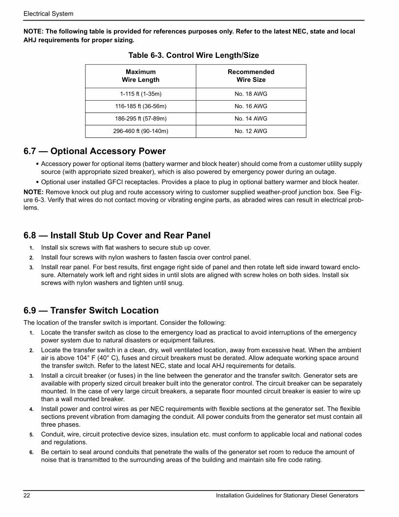
NOTE: The following table is provided for references purposes only. Refer to the latest NEC, state and local AHJ requirements for proper sizing.
6.7 — Optional Accessory Power• Accessory power for optional items (battery warmer and block heater) should come from a customer utility supply
source (with appropriate sized breaker), which is also powered by emergency power during an outage. • Optional user installed GFCI receptacles. Provides a place to plug in optional battery warmer and block heater.
NOTE: Remove knock out plug and route accessory wiring to customer supplied weather-proof junction box. See Fig-ure 6-3. Verify that wires do not contact moving or vibrating engine parts, as abraded wires can result in electrical prob-lems.
6.8 — Install Stub Up Cover and Rear Panel1. Install six screws with flat washers to secure stub up cover.2. Install four screws with nylon washers to fasten fascia over control panel. 3. Install rear panel. For best results, first engage right side of panel and then rotate left side inward toward enclo-
sure. Alternately work left and right sides in until slots are aligned with screw holes on both sides. Install six screws with nylon washers and tighten until snug.
6.9 — Transfer Switch LocationThe location of the transfer switch is important. Consider the following:
1. Locate the transfer switch as close to the emergency load as practical to avoid interruptions of the emergency power system due to natural disasters or equipment failures.
2. Locate the transfer switch in a clean, dry, well ventilated location, away from excessive heat. When the ambient air is above 104° F (40° C), fuses and circuit breakers must be derated. Allow adequate working space around the transfer switch. Refer to the latest NEC, state and local AHJ requirements for details.
3. Install a circuit breaker (or fuses) in the line between the generator and the transfer switch. Generator sets are available with properly sized circuit breaker built into the generator control. The circuit breaker can be separately mounted. In the case of very large circuit breakers, a separate floor mounted circuit breaker is easier to wire up than a wall mounted breaker.
4. Install power and control wires as per NEC requirements with flexible sections at the generator set. The flexible sections prevent vibration from damaging the conduit. All power conduits from the generator set must contain all three phases.
5. Conduit, wire, circuit protective device sizes, insulation etc. must conform to applicable local and national codes and regulations.
6. Be certain to seal around conduits that penetrate the walls of the generator set room to reduce the amount of noise that is transmitted to the surrounding areas of the building and maintain site fire code rating.
Table 6-3. Control Wire Length/Size
Maximum Wire Length
Recommended Wire Size
1-115 ft (1-35m) No. 18 AWG
116-185 ft (36-56m) No. 16 AWG
186-295 ft (57-89m) No. 14 AWG
296-460 ft (90-140m) No. 12 AWG

Electrical System
Installation Guidelines for Stationary Diesel Generators 23
6.10 — Battery6.10.1— General Cautions
• Stationary emergency generators installed with automatic transfer switches will crank and start automat-ically when NORMAL (UTILITY) source voltage is removed or is below an acceptable preset level. To pre-vent automatic startup and possible injury to personnel, do not connect battery cables until NORMAL source voltage at the transfer switch is correct and the system is ready to be placed into operation.
• Storage batteries give off EXPLOSIVE hydrogen gas. This gas can form an explosive mixture around the battery for several hours after charging. The slightest spark can ignite the gas and cause an explosion. An explosion can shatter the battery and cause blindness or other injury. Any area that houses a storage battery must be properly ventilated. Do not allow smoking, open flame, sparks, or any spark producing tools or equipment near the battery.
• When working on the battery, always remove watches, rings, or other metal objects, and only use tools that have insulated handles.
• Discharge static electricity from the body before touching the battery by first touching a grounded metal surface.
• Do not lay tools or metal parts on top of the battery.• Wear full eye protection and protective clothing.• Where electrolyte contacts the skin, wash it off immediately with water. If contact is with eyes, flush thor-
oughly and immediately with water and seek medical attention.• Battery electrolyte fluid is an extremely caustic sulfuric acid solution that can cause severe burns. Do
not permit fluid to contact eyes, skin, clothing, painted surfaces, etc. Wear protective goggles, protective clothing and gloves when handling a battery. If fluid is spilled, flush the affected area immediately with clear water.
• Spilled electrolyte is to be washed down with an acid neutralizing agent. A common practice is to use a solution of 1 pound (500 grams) bicarbonate of soda to 1 gallon (4 liters) of water. The bicarbonate of soda solution is to be added until the evidence of reaction (foaming) has ceased. The resulting liquid is to be flushed with water.
6.10.2— Battery Size The ability to start the engine depends upon battery capacity, ambient temperatures and coolant and oil temperatures. The engine/generator set Data Sheet lists minimum recommended battery capacity at various ambient temperatures. The recommended battery capacities are listed under cold cranking amps (CCA) at 0 °F ( 18 °C). Battery capacities decrease as ambient temperatures decrease, so it is important to specify batteries with the appropriate CCA rating at a temperature no higher than the minimum ambient temperature for the application.
6.10.3— Battery ReplacementFor battery replacement, consult the unit specification sheet for battery size. Battery cables are factory connected at the generator connection points. Fill the battery with the proper electrolyte fluid if necessary and have the battery fully charged before installing.
6.10.3.1— Preliminary Instructions1. Open the viewing window. 2. Press the OFF button on the control panel keypad. The red LED above the button illuminates to confirm that the
system is in the OFF mode. 3. Move the Main Circuit Breaker switch down to the OFF (Open) position. 4. Pull up rubber flap covering fuse holder and remove 7.5 amp fuse. 5. Turn off utility power supply to the battery charger circuit.

Electrical System
24 Installation Guidelines for Stationary Diesel Generators
6.10.3.2— Check Condition and Clean1. Verify that top of battery is clean and dry. 2. Clean cable connectors and battery terminals using a wire brush, if necessary.3. Inspect battery screws, clamps and cables for breakage, loose connections and corrosion. Tighten and clean as
necessary.4. Inspect battery for discoloration, raised top or a warped or distorted case, which might indicate that the battery
has been frozen, overheated or overcharged.5. Inspect the battery case for cracks or leaks.6. Check the battery fluid level of unsealed batteries. See Subsection 6.10.3.3�Check Fluid Level.7. Check the battery state of charge. See Subsection 6.10.3.4�Check State of Charge.
6.10.3.3— Check Fluid LevelCheck the fluid level of unsealed batteries. If necessary, fill with distilled water only. DO NOT use tap water.
6.10.3.4— Check State of ChargeCheck the state of charge using a Digital Multimeter. If below the manufacturer's recommendations, recharge battery and retest. Replace battery if necessary.
6.10.3.5— Removal/InstallationRemoval
CAUTION: Always disconnect the negative battery cable first. If the positive cable should contact ground with the negative cable installed, the resulting sparks may cause a battery explosion which could result in serious injury.
2.3L Models1. Remove battery negative cable (black) from
battery negative (-) terminal.2. Remove battery positive cable (red) from bat-
tery positive (+) terminal.3. Install rubber protective cover over battery posi-
tive (+) terminal. See A of Figure 6-6.4. Loosen two screws with nylon washers to
release battery hold-down clamp from battery tray.
5. Grasp battery strap next to battery positive (+) terminal, and lift battery. See B of Figure 6-6.
6. When battery tilts sideways, remove from open-ing.
7. Remove rubber protective cover from battery positive (+) terminal.
2.4L/3.4L Models1. Remove battery negative cable (black) from
battery negative (-) terminal.2. Remove battery positive cable (red) from bat-
tery positive (+) terminal.3. Loosen two screws with nylon washers to
release battery hold-down clamp. 4. Remove battery from tray.
Figure 6-6. Install Battery (2.3L Models)
A = Protective Cover B = Battery Strap

Electrical System
Installation Guidelines for Stationary Diesel Generators 25
InstallationCAUTION: Always connect the positive battery cable first. If the positive cable should contact ground with the negative cable installed, the resulting sparks may cause a battery explosion which could result in serious injury.
2.3L Models1. Install rubber protective cover over battery positive (+) terminal. 2. Grasp battery strap next to battery positive (+) terminal, and lift battery. 3. When battery tilts sideways, insert into opening. 4. Return battery to the horizontal position while sliding it onto battery tray. 5. Tighten two screws with nylon washers to secure hold-down clamp to battery tray.6. Remove rubber protective cover from battery positive (+) terminal.7. Install battery positive cable (red) to battery positive (+) terminal.8. Install battery negative cable (black) to battery negative (-) terminal.
2.4L/3.4L ModelsInstallation
1. Install battery onto tray.2. Tighten two screws with nylon washers to secure hold-down clamp to battery tray.3. Install battery positive cable (red) to battery positive (+) terminal.4. Install battery negative cable (black) to battery negative (-) terminal.
6.10.3.6— Final Instructions1. Pull up rubber flap covering fuse holder and install 7.5 amp fuse. 2. Move the Main Circuit Breaker switch up to the ON (Closed) position. 3. Turn on the utility power supply to the battery charger circuit.4. If the unit was previously operational, press the AUTO button on the control panel keypad. The green LED above
the button illuminates to confirm that the system is in the AUTO mode. 5. Close the viewing window.
6.11 — Operational ChecksCAUTION: The following procedures require special tools and skills. Contact a Generac Dealer or an authorized service provider to perform these tasks.
6.11.1— Self TestUpon power up, the controller goes through a system self test which checks for the presence of utility voltage on the DC circuits. This is done to prevent damage if the installer mistakenly connects AC utility power sense wires into the DC terminal block. If utility voltage is detected, the controller displays a warning message and locks out the generator, thereby preventing damage to the controller. Remove power to the controller to clear this warning.Utility voltage must be turned on and present at the N1 and N2 terminals inside the generator control panel for this test to be performed and pass.Before starting, complete the following:
1. Verify that the generator is OFF. The red LED above the OFF key on the control panel keypad illuminates to con-firm that the system is in the OFF mode.
2. Verify that the Main Circuit Breaker switch on the generator control panel is in the OFF (Open) position. 3. Turn off all circuit breakers/electrical loads that will be powered by the generator.4. Check the engine crankcase oil level, coolant level, and fuel level, if necessary.

Electrical System
26 Installation Guidelines for Stationary Diesel Generators
During initial start up only, the generator may exceed the normal number of start attempts and experience an “over crank” fault. This is due to accumulated air in the fuel system during installation. Reset the control board and restart up to two more times, if necessary. If unit fails to start, contact the local dealer for assistance.
6.11.2— Check Manual Transfer Switch OperationRefer to the “Manual Transfer Operation” section of the owner’s manual for procedures.NOTE: Also use the appropriate transfer switch owner’s manual for manual and automatic system test.
CAUTION: Do not attempt manual transfer switch operation until all power voltage supplies to the transfer switch have been positively turned off. Failure to turn off all power voltage supplies will result in extremely hazardous and possibly fatal electrical shock.
6.11.3— Electrical ChecksComplete electrical checks as follows:
1. Verify that the generator is OFF. The red LED above the OFF key on the control panel keypad illuminates to con-firm that the system is in the OFF mode.
2. Verify that the Main Circuit Breaker switch on the generator control panel is in the OFF (Open) position. 3. Turn OFF all circuit breakers/electrical loads that will be powered by the generator.4. Turn on the utility power supply to the transfer switch using the means provided (such as a utility main line circuit
breaker).
CAUTION: The transfer switch is now electrically “hot.” Contact with “hot” parts will result in extremely hazardous and possibly fatal electrical shock.
5. Use an accurate AC voltmeter to check utility power source voltage across transfer switch terminals N1, N2, and N3 (if three phase). Normal line-to-line voltage should be equivalent to rated unit voltage.
6. Check utility power source voltage across terminals N1, N2, and N3 (if three phase) and the transfer switch neu-tral lug.
7. When certain that utility supply voltage is compatible with transfer switch and load circuit ratings, turn OFF the utility power supply to the transfer switch.
8. Press the MANUAL key on the control panel keypad to crank and start the engine.9. Allow the engine to warm up for about five minutes. Move the Main Circuit Breaker switch on the generator con-
trol panel up to the ON (Closed) position.
CAUTION: Generator power voltage is now supplied to the transfer switch. Contact with live transfer switch parts will result in dangerous and possibly fatal electrical shock.
10. Connect an accurate AC voltmeter and a frequency meter across transfer switch terminal lugs E1, E2, and E3 (if three phase).
11. Successively connect the AC voltmeter test leads across terminal lugs E1, E2, and E3 (if three phase) and neu-tral; then across E2 and neutral. Voltage reading in each case should match utility voltage reading. If system is three phase, verify that generator phase rotation matches utility phase rotation.
12. Move the Main Circuit Breaker switch on the generator control panel down to the OFF (Open) position. 13. Press the OFF key on the control panel keypad to shut the engine down.
CAUTION: Do not proceed unless certain that generator AC voltage and frequency are correct and within the stated limits.
6.11.4— Test Generator Under LoadTo test the generator set with electrical loads applied, proceed as follows:
1. Verify that the generator is OFF. The red LED above the OFF key on the control panel keypad illuminates to con-firm that the system is in the OFF mode.

Electrical System
Installation Guidelines for Stationary Diesel Generators 27
2. Turn OFF all breakers/electrical loads that will be powered by the generator.3. Turn OFF the utility power supply to the transfer switch, using the means provided (such as a utility main line cir-
cuit breaker).
CAUTION: Do not attempt manual transfer switch operation until all power voltage supplies to the transfer switch have been positively turned off. Failure to turn off all power voltage supplies will result in extremely hazardous and possibly fatal electrical shock.
4. Manually set the transfer switch to the STANDBY position, i.e., load terminals connected to the generator’s E1, E2, and E3 (if three phase) terminals. The transfer switch operating lever should be down.
5. Press the MANUAL key on the control panel keypad. The engine should crank and start immediately.6. Allow the engine to warm up for a few minutes.7. Move the Main Circuit Breaker switch on the generator control panel up to the ON (Closed) position. Loads are
now powered by the standby generator.8. Turn ON the circuit breaker/electrical loads powered by the generator.9. Connect a calibrated AC voltmeter and a frequency meter across terminal lugs E1, E2, and E3 (if three phase).
Voltage should be approximately unit rated voltage.10. Let the generator run at full rated load for 20-30 minutes. Listen for unusual noises, vibration or other indications
of abnormal operation. Check for oil leaks, evidence of overheating, etc.11. When testing under load is complete, turn OFF electrical loads.12. Move the Main Circuit Breaker switch on the generator control panel down to the OFF (Open) position. 13. Allow the engine to run at no-load for 2-5 minutes.14. Press the OFF key on the control panel keypad to shut the engine down.
6.11.5— Check Automatic OperationTo check the system for proper automatic operation, proceed as follows:
1. Verify that the generator is OFF. The red LED above the OFF key on the control panel keypad illuminates to con-firm that the system is in the OFF mode.
2. Install front cover over the transfer switch.3. Turn ON the utility power supply to the transfer switch, using the means provided (such as a utility main line cir-
cuit breaker).NOTE: Transfer Switch will transfer back to utility position.
4. Move the Main Circuit Breaker switch on the generator control panel up to the ON (Closed) position. 5. Press the AUTO key on the control panel keypad. The system is now ready for automatic operation.6. Turn OFF the utility power supply to the transfer switch.
With the generator ready for automatic operation, the engine will crank and start when the utility source power is turned OFF after a 10 second delay (factory default setting). After starting, the transfer switch connects load circuits to the standby side. Let the system operate through its entire automatic sequence of operation.With the generator running and loads powered by generator AC output, turn ON the utility power supply to the transfer switch. The system transfers back to the utility position and then runs through the cool down cycle and shuts down.
6.12 — Installation Summary1. Ensure that the installation has been properly performed as outlined by the manufacturer and that it meets all
applicable laws and codes.2. Test and confirm proper operation of the system as outlined in the appropriate installation and owner’s manuals.3. Educate the customer on the proper operation, maintenance and service call procedures.
IMPORTANT! If the customer ever finds it necessary to turn the generator off during prolonged utility outages to conserve fuel or perform maintenance, alert them to these important steps:

Electrical System
28 Installation Guidelines for Stationary Diesel Generators
To turn the generator OFF (while running in AUTO and online):1. Turn OFF (or open) the main Utility disconnect.2. Move the Main Circuit Breaker switch on the generator control panel down to the OFF (Open) position. 3. Press the OFF key on the control panel keypad. The red LED above the button illuminates to confirm that the
system is in the OFF mode. To turn the generator back ON:
1. Press the AUTO key on the control panel keypad. Allow the unit to start and warm-up for a few minutes.2. Move the Main Circuit Breaker switch on the generator control panel up to the ON (Closed) position.
The system will now be operating in the automatic mode. The main utility disconnect can be turned ON (Closed), but to shut the unit off, this complete process must be repeated.
Installation Guidelines for Stationary Diesel Generators 29
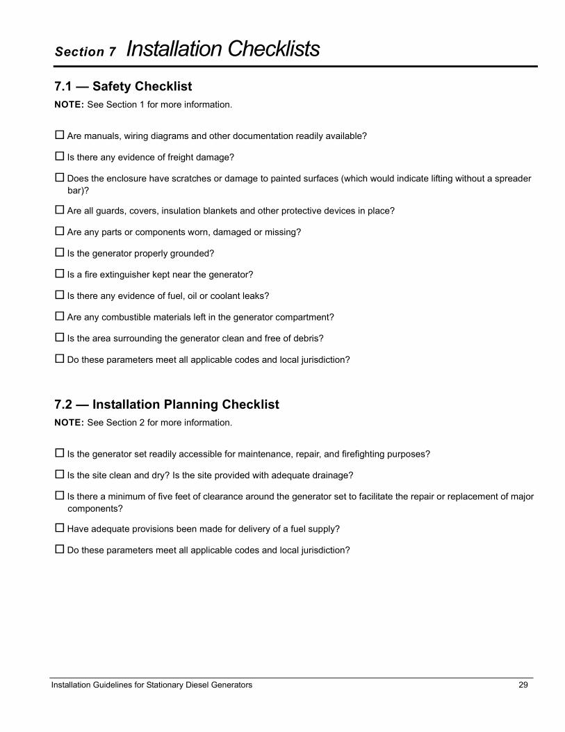
Section 7 Installation Checklists7.1 — Safety ChecklistNOTE: See Section 1 for more information.
Are manuals, wiring diagrams and other documentation readily available?
Is there any evidence of freight damage?
Does the enclosure have scratches or damage to painted surfaces (which would indicate lifting without a spreader bar)?
Are all guards, covers, insulation blankets and other protective devices in place?
Are any parts or components worn, damaged or missing?
Is the generator properly grounded?
Is a fire extinguisher kept near the generator?
Is there any evidence of fuel, oil or coolant leaks?
Are any combustible materials left in the generator compartment?
Is the area surrounding the generator clean and free of debris?
Do these parameters meet all applicable codes and local jurisdiction?
7.2 — Installation Planning ChecklistNOTE: See Section 2 for more information.
Is the generator set readily accessible for maintenance, repair, and firefighting purposes?
Is the site clean and dry? Is the site provided with adequate drainage?
Is there a minimum of five feet of clearance around the generator set to facilitate the repair or replacement of major components?
Have adequate provisions been made for delivery of a fuel supply?
Do these parameters meet all applicable codes and local jurisdiction?

Installation Checklists
30 Installation Guidelines for Stationary Diesel Generators
7.3 — Foundations & Mounting ChecklistNOTE: See Section 3 for more information.
Is the generator set installed on a concrete pad capable of supporting its weight and accessories?
Is the generator securely fastened to the concrete pad using suitable grade, size and style fasteners?
Is the concrete pad seated on a prepared solid subsurface using appropriate reinforcing bar or expanded wire mesh?
Does the concrete pad extend beyond the frame rails at least 18 inches and above the surrounding surface by 3-8 inches?
Is the concrete pad flat and level to within 1/2 inch?
Is a containment dike provided for fuel and oil spillage?
Is the bottom of the generator set enclosed?
Do all fuel, coolant, exhaust, and electrical lines have flexible sections where they connect to the generator?
Is all piping properly supported and secured?
Do these parameters meet all applicable codes and local jurisdiction?
7.4 — Ventilation System ChecklistNOTE: See Section 4 for more information.
Is there sufficient air flow for cooling and ventilation?
Does the air inlet face the direction of prevailing winds?
Has system been properly protected from freeze up and corrosion?
Have standby equipment heaters been specified?
Have all electrically driven devices been connected to load side of EPS connection points?
Does the air outlet face noise sensitive areas without noise attenuating devices?
Does the installation appear to have the necessary accessories to enable fast, reliable starting and operation in adverse weather conditions (such as engine jacket water heaters, battery warmers, etc.)?
Do these parameters meet all applicable codes and local jurisdiction?

Installation Checklists
Installation Guidelines for Stationary Diesel Generators 31
7.5 — Diesel Fuel System ChecklistNOTE: See Section 5 for more information.
Is black iron or steel piping used from the fuel source to the flexible connection at the generator?
Is any galvanized pipe used for diesel fuel applications?
Are any pipe or fittings constructed of cast iron or aluminum?
Is there evidence of leakage or damage at any hoses, clamps or fittings?
Has the fuel system been primed (bled of air)?
Do these parameters meet all applicable codes and local jurisdiction?
7.6 — Electrical System Checklist NOTE: See Section 6 for more information.
Is all wiring correctly sized for load and length of run?
Is all wiring correctly routed?
Is all wiring correctly supported?
Is all wiring correctly connected?
Are wire lugs fastened to buss bars using appropriate hardware? Is hardware properly tightened to specified torque?
Are all other terminals correctly tightened using the specified torque?
Are batteries correctly sized?
Are batteries correctly installed?
Are the battery fluid levels correct?
Are battery cables and connections clean and free of corrosion?
Are the battery cables correctly connected? Are the terminal lugs correctly tightened?
Is the battery condition and state of charge acceptable?
Is area housing storage battery properly ventilated?
Are batteries located near a source of flame or spark?
Are AC wire sizes and connections correct?
Are DC and communication wire sizes and connections correct?
Are DC and communication wires routed separately from AC wires?

Installation Checklists
32 Installation Guidelines for Stationary Diesel Generators
Are block heaters, battery charger, etc. properly matched with utility supply voltage?
Are battery charger and block heater properly connected?
If used, are remote start Wires 0 & 183 pulled and connected inside lower control panel of generator and inside transfer switch?
Is the AUTO/OFF/MANUAL switch in the “OFF” position?
Is the grounding rod installed?
Is the block heater operational?
Is the battery charger operational?
Are all AC electrical connections tight at the circuit breaker and transfer switch?
Are all electrical connections (wiring, wire ties, clamps, terminal ends, connectors) on the generator tight?
Are all electrical plugs throughout the generator seated correctly and fully inserted into their receptacles?
Is there proper voltage and phase rotation at the transfer switch?
Is manual operation of the transfer switch smooth and non-binding?
Are dip switch settings in transfer switch OK?
Do these parameters meet all applicable codes and local jurisdiction?


Part No. 0K4465 Rev. E 12/17/2013 Printed in USA© Generac Power Systems, Inc. All rights reservedSpecifications are subject to change without notice.No reproduction allowed in any form without prior written consent from Generac Power Systems, Inc.
Generac Power Systems, Inc.S45 W29290 Hwy. 59Waukesha, WI 53189
1-888-GENERAC (1-888-436-3722)generac.com