ProtectIT Multifunction Protection and Switchbay … Protection and Switchbay Control unit...
55
Protect IT Multifunction Protection and Switchbay Control Unit REF542plus ABB Level 0: Information
Transcript of ProtectIT Multifunction Protection and Switchbay … Protection and Switchbay Control unit...
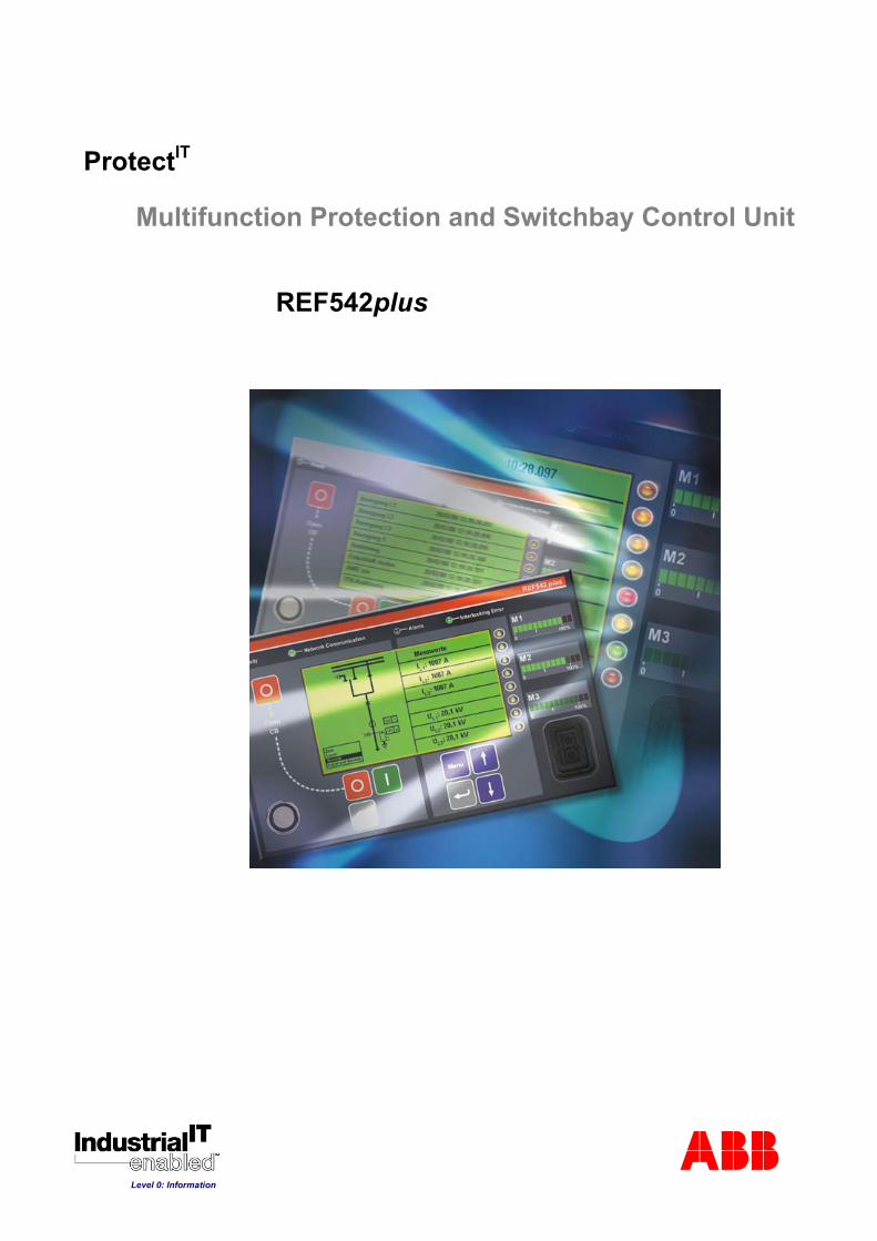
ProtectIT
Multifunction Protection and Switchbay Control Unit
REF542plus
ABB
Level 0: Information
Multifunction Protection and Switchbay Control unit REF542plus
Table of Contents 1 General .............................................................................................................4
2 Functions .........................................................................................................8 2.1 Configuration.....................................................................................................8 2.2 Operation ........................................................................................................10
2.2.1 LCD display ..................................................................................10 2.2.2 Status Indication ...........................................................................11 2.2.2.1 Operational status ........................................................................11 2.2.2.2 Communication status ..................................................................11 2.2.2.3 Alarm indication ............................................................................11 2.2.2.4 Interlocking status.........................................................................11 2.2.3 LED Indication ..............................................................................11 2.2.4 Bar displays ..................................................................................11 2.2.5 Control push buttons ....................................................................12 2.2.6 Electronic key ...............................................................................12
2.3 Measurement ..................................................................................................12 2.3.1 Values measured directly .............................................................12 2.3.2 Calculated values .........................................................................13 2.3.3 Other values .................................................................................13
2.4 Protection ........................................................................................................13 2.5 Control.............................................................................................................14 2.6 Event recording ...............................................................................................14 2.7 Fault recording ................................................................................................15 2.8 Real time clock................................................................................................16 2.9 Process interface ............................................................................................16
2.9.1 Analog inputs ................................................................................16 2.9.2 Binary inputs and outputs .............................................................18
3 Diagnosis and monitoring............................................................................19
4 Analog output................................................................................................20
5 Communication .............................................................................................21
6 Housing..........................................................................................................23
7 Mechanical design ........................................................................................26 7.1 REF542plus standard case version: ...............................................................26 7.2 REF542plus wide case version:......................................................................26 7.3 Analog inputs ..................................................................................................26
8 List of the protection functions ...................................................................27
9 Technical data ...............................................................................................32 9.1 Analog input channels.....................................................................................32
9.1.1 Current and voltage transformer input values ..............................32 9.1.2 Current and voltage sensor input values......................................32
1VTA100001-Rev 6, en PTMV, 25.10.2002 REF 542 plus Technical Catalog 2/ 55 Updated and valid from version V4C01

Multifunction Protection and Switchbay Control unit REF542plus
9.2 Binary inputs and outputs................................................................................33 9.2.1 BIO module with mechanical output relays (version 3) ................33 9.2.2 BIO module with static outputs .....................................................34
9.3 Interfaces ........................................................................................................34 9.3.1 HMI Control Unit: ..........................................................................34 9.3.2 Central Unit:..................................................................................34
9.4 Analog output board (optional)........................................................................34 9.5 Communication (optional) ...............................................................................34 9.6 Power supply...................................................................................................35
9.6.1 Central Unit...................................................................................35 9.6.2 HMI Control Unit ...........................................................................35
9.7 Environmental conditions................................................................................35 9.8 Degree of protection by enclosure ..................................................................36
9.8.1 Central Unit...................................................................................36 9.8.2 RHMI Control Unit ........................................................................36
10 Type test ........................................................................................................37 10.1 Protection function ..........................................................................................37 10.2 Electro magnetic compatibility ........................................................................38
10.2.1 Emission test ................................................................................38 10.2.2 Immunity tests - enclosure port ....................................................39 10.2.3 Immunity tests - power supply port...............................................40 10.2.4 Immunity tests - communication ports..........................................41 10.2.5 Immunity tests – binary input and output ports.............................42
10.3 Insulation resistance .......................................................................................42 10.4 Mechanical robustness ...................................................................................42 10.5 Climatic conditions ..........................................................................................42
11 Connection Diagram.....................................................................................43 11.1 Connector Plate ..............................................................................................43 11.2 HMI Control Unit..............................................................................................44 11.3 REF542plus with mechanical binary I/O .........................................................45 11.4 REF542plus with solid state binary I/O ...........................................................48 11.5 REF542plus with mechanical binary I/O (version 2).......................................51 11.6 Analog input board versions ...........................................................................52
1VTA100001-Rev 6, en PTMV, 25.10.2002 REF 542 plus Technical Catalog 3/ 55 Updated and valid from version V4C01

Multifunction Protection and Switchbay Control unit REF542plus
1 General The REF542plus Multifunction Protection and Switchbay Control Unit is the further development of the former REF542 unit. Like its predecessor, it features the following functions:
Protection
Measurement
Control
Monitoring
All functions mentioned above and power quality functions are integrated in a programmable environment. The exceptional flexibility and scalability of these new generation devices lead to a smart and clean solution where the traditional approach would be ineffective and expensive.
The following figures show examples of the REF542plus installation in several switchboards.
Figure 1: REF542plus installed in gas insulated switchboards (GIS)
1VTA100001-Rev 6, en PTMV, 25.10.2002 REF 542 plus Technical Catalog 4/ 55 Updated and valid from version V4C01
Multifunction Protection and Switchbay Control unit REF542plus
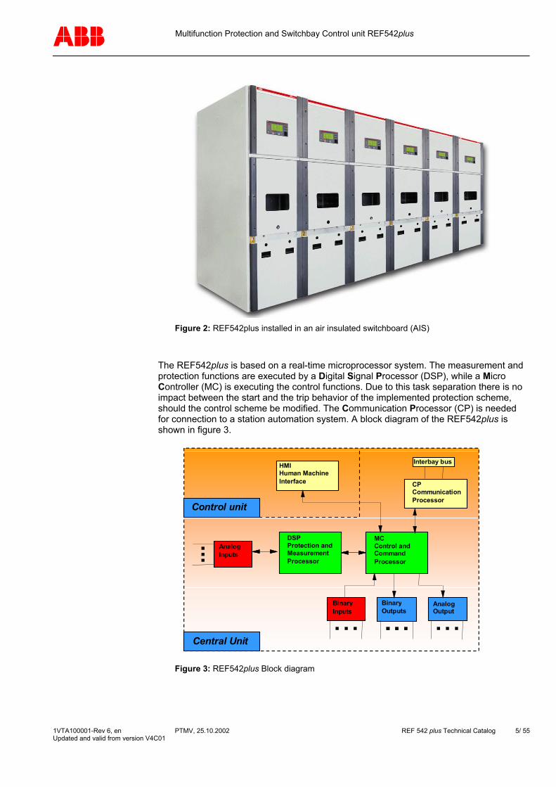
Figure 2: REF542plus installed in an air insulated switchboard (AIS)
The REF542plus is based on a real-time microprocessor system. The measurement and protection functions are executed by a Digital Signal Processor (DSP), while a Micro Controller (MC) is executing the control functions. Due to this task separation there is no impact between the start and the trip behavior of the implemented protection scheme, should the control scheme be modified. The Communication Processor (CP) is needed for connection to a station automation system. A block diagram of the REF542plus is shown in figure 3.
BinaryInputs
AnalogOutput
BinaryOutputs
MCControl andCommandProcessor
CPCommunicationProcessor
DSPProtection andMeasurementProcessor
AnalogInputs
Interbay busHMIHuman MachineInterface
Control unit
Central Unit
Figure 3: REF542plus Block diagram
1VTA100001-Rev 6, en PTMV, 25.10.2002 REF 542 plus Technical Catalog 5/ 55 Updated and valid from version V4C01
Multifunction Protection and Switchbay Control unit REF542plus
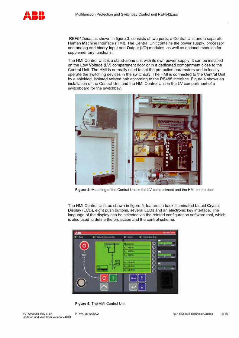
REF542plus, as shown in figure 3, consists of two parts, a Central Unit and a separate Human Machine Interface (HMI). The Central Unit contains the power supply, processor and analog and binary Input and Output (I/O) modules, as well as optional modules for supplementary functions.
The HMI Control Unit is a stand-alone unit with its own power supply. It can be installed on the Low Voltage (LV) compartment door or in a dedicated compartment close to the Central Unit. The HMI is normally used to set the protection parameters and to locally operate the switching devices in the switchbay. The HMI is connected to the Central Unit by a shielded, isolated twisted pair according to the RS485 interface. Figure 4 shows an installation of the Central Unit and the HMI Control Unit in the LV compartment of a switchboard for the switchbay.
Figure 4: Mounting of the Central Unit in the LV compartment and the HMI on the door
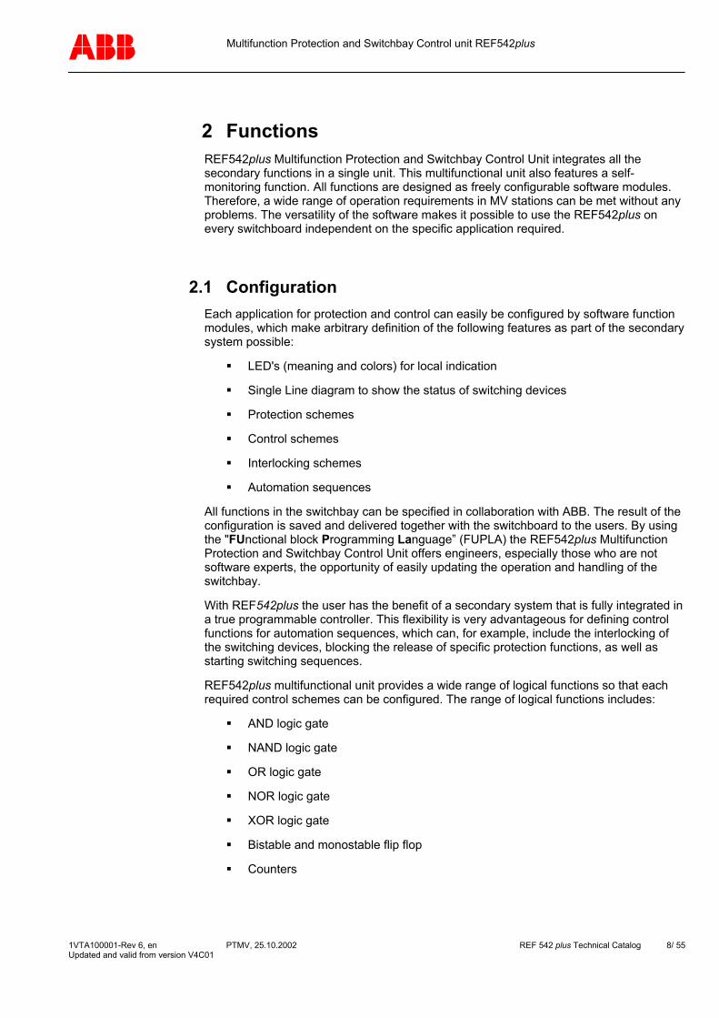
The HMI Control Unit, as shown in figure 5, features a back-illuminated Liquid Crystal Display (LCD), eight push buttons, several LEDs and an electronic key interface. The language of the display can be selected via the related configuration software tool, which is also used to define the protection and the control scheme.
Figure 5: The HMI Control Unit
1VTA100001-Rev 6, en PTMV, 25.10.2002 REF 542 plus Technical Catalog 6/ 55 Updated and valid from version V4C01

Multifunction Protection and Switchbay Control unit REF542plus
The left half of the LCD display is reserved for the Single Line diagram. The right half is used to display the appropriate menu or submenu as determined by the user. Two different electronic keys with different access rights are available. Each of the keys are programmed to permit either:
protection functions parameterization of the
mode selection of the control functions
Three freely programmable LED bars have been provided on the front of the HMI Control Unit. Each LED bar consists of ten green and two red LEDs and is user configurable to display any required measurement value. The red LEDs are used to indicate values above the rated value.
The functions of the REF542plus can be tailored to the system requirements via a user-specific configuration. The user-specific configuration is loaded during commissioning. For that purpose the configuration computer, normally a personal computer (notebook) running Windows NT, is connected to the optical interface on the front side of the HMI Control Unit.
The interface of the multifunctional unit REF542plus to the Medium Voltage (MV) primary process is as follows:
Analog inputs to measure current and voltage signals from instrument transformers or non conventional sensors
Binary inputs with optical couplers for the galvanic separation of the external signals to be processed;
Binary outputs with conventional mechanical relays or static outputs for the control of switching devices;
Optional four channel analog outputs 0 to 20mA or 4 to 20 mA
Optional connection to ABB or third party station automation system.
REF542plus is a certified product for compliance to the IndustrialIT architecture concept of ABB.
IndustrialIT products can be effectively combined together into value-added systems and solutions in a “Plug&Produce” manner.
Compliance according to “Level 0: Information” ensures that all relevant product documentation – including the operation manual, instructions for installation and maintenance, electrical and mechanical drawings, test reports and specific order information -is online available, in electronic format, for access via software products and systems based on the ABB Aspect Integrator Platform.
In this way, significant benefits are enabled to the final user for much easier and effective installation, configuration, operation and maintenance of the product in the plant.
Detailed information on Industrial IT is available at http://www.abb.com/industrial it
1VTA100001-Rev 6, en PTMV, 25.10.2002 REF 542 plus Technical Catalog 7/ 55 Updated and valid from version V4C01
Multifunction Protection and Switchbay Control unit REF542plus
2 Functions REF542plus Multifunction Protection and Switchbay Control Unit integrates all the secondary functions in a single unit. This multifunctional unit also features a self-monitoring function. All functions are designed as freely configurable software modules. Therefore, a wide range of operation requirements in MV stations can be met without any problems. The versatility of the software makes it possible to use the REF542plus on every switchboard independent on the specific application required.
2.1 Configuration Each application for protection and control can easily be configured by software function modules, which make arbitrary definition of the following features as part of the secondary system possible:
LED's (meaning and colors) for local indication
Single Line diagram to show the status of switching devices
Protection schemes
Control schemes
Interlocking schemes
Automation sequences
All functions in the switchbay can be specified in collaboration with ABB. The result of the configuration is saved and delivered together with the switchboard to the users. By using the "FUnctional block Programming Language” (FUPLA) the REF542plus Multifunction Protection and Switchbay Control Unit offers engineers, especially those who are not software experts, the opportunity of easily updating the operation and handling of the switchbay.
With REF542plus the user has the benefit of a secondary system that is fully integrated in a true programmable controller. This flexibility is very advantageous for defining control functions for automation sequences, which can, for example, include the interlocking of the switching devices, blocking the release of specific protection functions, as well as starting switching sequences.
REF542plus multifunctional unit provides a wide range of logical functions so that each required control schemes can be configured. The range of logical functions includes:
AND logic gate
NAND logic gate
OR logic gate
NOR logic gate
XOR logic gate
Bistable and monostable flip flop
Counters
1VTA100001-Rev 6, en PTMV, 25.10.2002 REF 542 plus Technical Catalog 8/ 55 Updated and valid from version V4C01
Multifunction Protection and Switchbay Control unit REF542plus
Timers
Pulse generators
Memories
Similar to the free definition of the control scheme, each required protection scheme can be configured by the combination of the available protection function modules. For example, the following protection functions areavailable:
Definite time overcurrent protection
Inverse time overcurrent protection
Directional overcurrent protection
Under- or overvoltage protection
Distance protection
Differential protection for transformer and motor
Thermal protection for cable, transformer and motor
Reverse power protection
Synchronism check
Note The specific software configuration of the required protection scheme can only be carried out in-house at ABB.
The protection scheme parameters can be changed via the HMI Control Unit without using a personal computer. Additional functions can be excuted with a personal computer running the configuration software and connected to the optical interface on the front of the HMI unit.
These additional functions are:
Parameterization of the protection scheme,
Read-out of the current measurement values,
Read-out of the status of the binary inputs and outputs,
Read-out of the fault recorder and
Viewing of the FUPLA logic I/O states
1VTA100001-Rev 6, en PTMV, 25.10.2002 REF 542 plus Technical Catalog 9/ 55 Updated and valid from version V4C01
Multifunction Protection and Switchbay Control unit REF542plus
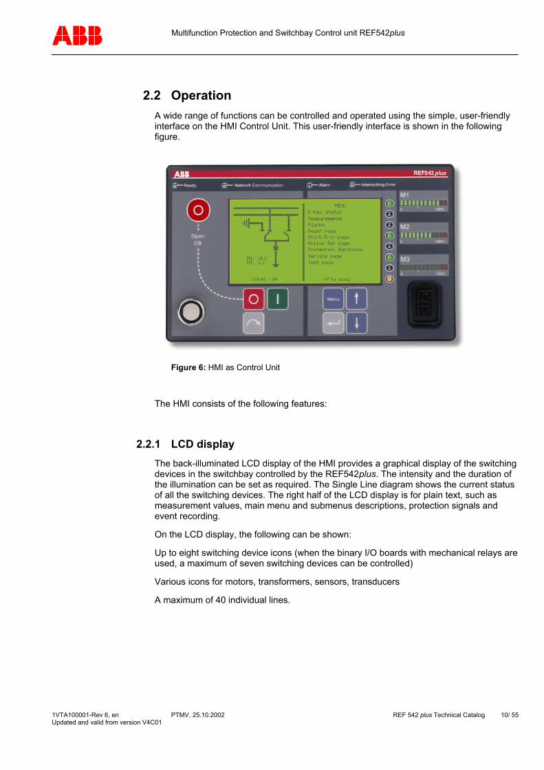
2.2 Operation A wide range of functions can be controlled and operated using the simple, user-friendly interface on the HMI Control Unit. This user-friendly interface is shown in the following figure.
Figure 6: HMI as Control Unit
The HMI consists of the following features:
2.2.1 LCD display The back-illuminated LCD display of the HMI provides a graphical display of the switching devices in the switchbay controlled by the REF542plus. The intensity and the duration of the illumination can be set as required. The Single Line diagram shows the current status of all the switching devices. The right half of the LCD display is for plain text, such as measurement values, main menu and submenus descriptions, protection signals and event recording.
On the LCD display, the following can be shown:
Up to eight switching device icons (when the binary I/O boards with mechanical relays are used, a maximum of seven switching devices can be controlled)
Various icons for motors, transformers, sensors, transducers
A maximum of 40 individual lines.
1VTA100001-Rev 6, en PTMV, 25.10.2002 REF 542 plus Technical Catalog 10/ 55 Updated and valid from version V4C01

Multifunction Protection and Switchbay Control unit REF542plus
2.2.2 Status Indication Four system LEDs, describe in the following chapters, indicate the status of the REF542plus.
2.2.2.1 Operational status
On the HMI front panel, the operational status is called 'Ready' and is displayed by a green LED. The unit is not operational when this LED is off, and this occurs for example during the downloading of the configuration for the operation of the switchbay or if a fault condition is detected in the Central Unit.
2.2.2.2 Communication status
On the HMI front panel, this communication status is called 'Network Communication'. If the REF542plus is to be connected to a station automation system, the appropriate communications board is required. In this case a green LED is used to indicate the correct operational status of this optional board. The LED color changes to red if a communication failure has occurred.
2.2.2.3 Alarm indication
Several arbitrary alarm conditions can be defined and configured by the user. If one of these conditions is fulfilled, the red LED will be on.
2.2.2.4 Interlocking status
The LED is green if no interlocking conditions have been violated. In case of a switching action, which violates the interlock conditions such as switching a disconnector in the closed condition of the Circuit Breaker (CB), the color will change temporarily to red.
2.2.3 LED Indication Eight freely programmable, three color LED's are provided for local indication. The number of LED display options can be quadrupled through the menu structure. As a result, a total of 32 indication options are available for status indication regarding protection, control, monitoring and supervision functions.
2.2.4 Bar displays Three freely programmable LED bars are provided for showing the measurement values. The LED bars are used to display arbitrary measurement values as required. Each bar consists of ten green and two red LEDs. The nominal values of each LED bar, which corresponds to the ten green LEDs are defined by the configuration software. If the measurement values are higher than the rated values, the red LEDs will gets illuminated indicating an overload situation.
1VTA100001-Rev 6, en PTMV, 25.10.2002 REF 542 plus Technical Catalog 11/ 55 Updated and valid from version V4C01
Multifunction Protection and Switchbay Control unit REF542plus
2.2.5 Control push buttons The control push buttons are used for operation of the switching devices during local control. A total of eight push buttons are available, four for commanding the primary equipment and four for browsing the display. The emergency push button can be configured in the FUPLA to open the circuit breaker when pressed simultaneously with the normal open push button.
2.2.6 Electronic key Two different electronic keys are provided. One key can only be used for the protection scheme parametrization. The other one is for control modes selection: local, remote or local/remote. By using these two keys a certain separation between protection and control operation can be achieved. If required a general key that permits access to both modes is provided. The sensor for recognizing which electronic key has been used is located on the front panel of the HMI Control Unit.
2.3 Measurement REF542plus can have a maximum of 8 analogue input channels for measuring current and voltage signals. These channels are organized into three groups.
Group 1 and group 2 have to be homogeneous, that means they can measure 3 currents or 3 voltages. For example, measurement of 1 current and 2 voltages is not allowed. Group 3 can get any type of signals: 2 currents, 2 voltages, 1 current and 1 voltage, etc. Channel 8 in the current REF542plus release can be used for measurement purposes only (no protection). REF542plus analogue inputs are very flexible, as this flexibility is needed to support all the protection functions of the unit itself.
Group1 and group 2 can be used for homogeneous current or voltage measurements both from instrument transformers and non conventional sensors. Group 3 can be used in a heterogeneous way, as well with instrument transformers as also with sensors. Channel 7 in group3 can be used for earth fault current with current transformer type input; or for the synchronism check function with voltage transformer type input.
The most common configuration uses three current and three voltage inputs and one earth fault current input. All values are shown on the display as primary values. The values registered over an extended time period, for example energy, number of CB operations, maximum and measurement values are permanently saved. Even after power interruptions this data is still available. Using this common configuration, the following measured values are displayed:
2.3.1 Values measured directly Line currents, three phases
Phase voltages, three phases
Earth current or residual voltage
Frequency
From the above measured quantities the following values can be calculated:
1VTA100001-Rev 6, en PTMV, 25.10.2002 REF 542 plus Technical Catalog 12/ 55 Updated and valid from version V4C01

Multifunction Protection and Switchbay Control unit REF542plus
2.3.2 Calculated values Line voltages, three phases
Earth current or residual voltage
Average value/maximum value current, three-phase (determined over several minutes)
Apparent, active and reactive power
Power factor
Active and reactive energy
Moreover, the following quantities for monitoring purposes can be provided:
2.3.3 Other values Operating hours
Switching cycles
Total switched currents
Metering pulses from an external metering device (up to 10)
2.4 Protection The REF542plus offers a wide range of functions for protection. As mentioned before, a wide range of protection schemes for the protection of several system components can be configured. The available protection functions can be combined together to form the required protection scheme. Figure 7 shows an example of a configured protection scheme.
Figure 7: FUPLA protection scheme
1VTA100001-Rev 6, en PTMV, 25.10.2002 REF 542 plus Technical Catalog 13/ 55 Updated and valid from version V4C01
Multifunction Protection and Switchbay Control unit REF542plus
2.5 Control The REF542plus permits convenient local operation with full interlocking against switching errors. The switch position of the various switching devices in the switchbay can be shown on the LCD display of the HMI Control Unit. If local control mode is selected, switching actions can be input locally using the control push buttons on the HMI Control Unit. Switching to another control mode can only be achieved by using the correct electronic key.
In remote control mode, only switching actions from a remote control unit like a station automation system are feasible. A special control mode, Local and Remote, is provided for users who want to perform simultaneous Local and Remote switching.
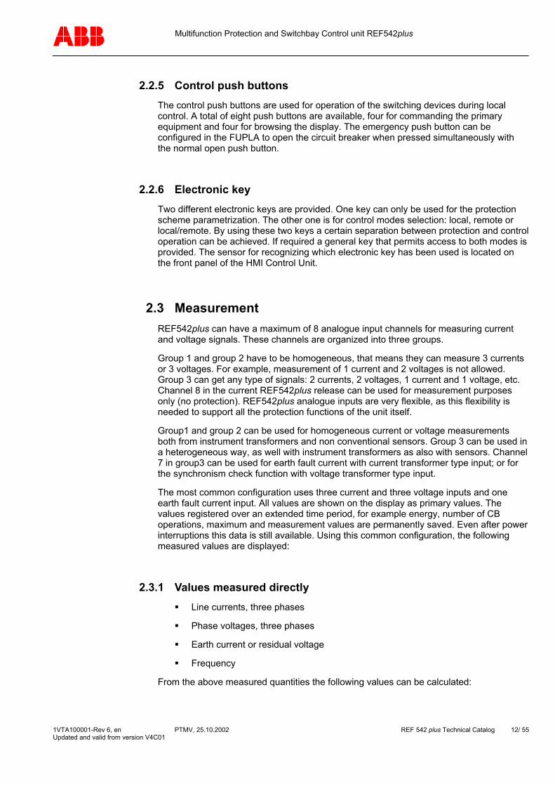
Interlocking between the switchbays connected to the same bus bar system can also be taken into account. This requires the availability of status information of the switching devices to and from other switchbays. The status information must be provided either by a conventional, hard wired ring bus system or by the more sophisticated ABB station automation system. Figure 8 shows an example of a configured control scheme of the CB.
Figure 8: FUPLA control scheme
2.6 Event recording The last 30 recorded events can be shown locally on the LCD display of the HMI unit. The events are mostly related to protection activities. As well as displaying the event name, additional information about the event, time, date and the RMS value of the short circuit current switched off by the CB are provided. Each event is stamped with the time and date. The time is taken from the internal clock on the REF542plus, which can be synchronized by the station automation system. In the next figure, a list of recorded events is shown.
1VTA100001-Rev 6, en PTMV, 25.10.2002 REF 542 plus Technical Catalog 14/ 55 Updated and valid from version V4C01

Multifunction Protection and Switchbay Control unit REF542plus
Figure 9: Event list on the LCD of the HMI
2.7 Fault recording The multifunctional unit REF542plus is equipped with a fault recorder module, which record and encode analog and binary data. The number of recorded data channels depends on the initial configuration. Up to seven signals of the analog channels and 32 binary signals can be recorded. The analog input signals are recorded with a sampling rate of 1.2 kHz for a period of at least 1-second and for a maximum of 5 seconds. The recording time is a combination of pre- and post fault time. The records are saved using a typical ring buffer process, i.e. the oldest fault record is always overwritten with a new one. The number of saved fault records depends on the record time. For example, a maximum of 5 fault records can be saved with a recording time of 1s.
Fault records can be exported and converted by the configuration software. The transfer of fault records can be done also via the interbay. Figure 10 shows a record of a cross country fault in an earth fault compensated MV system starting with the earth fault.
Figure 10: Record of a cross country fault in an MV system
1VTA100001-Rev 6, en PTMV, 25.10.2002 REF 542 plus Technical Catalog 15/ 55 Updated and valid from version V4C01
Multifunction Protection and Switchbay Control unit REF542plus
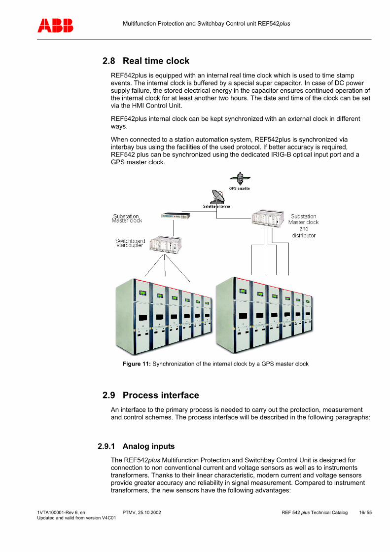
2.8 Real time clock REF542plus is equipped with an internal real time clock which is used to time stamp events. The internal clock is buffered by a special super capacitor. In case of DC power supply failure, the stored electrical energy in the capacitor ensures continued operation of the internal clock for at least another two hours. The date and time of the clock can be set via the HMI Control Unit.
REF542plus internal clock can be kept synchronized with an external clock in different ways.
When connected to a station automation system, REF542plus is synchronized via interbay bus using the facilities of the used protocol. If better accuracy is required, REF542 plus can be synchronized using the dedicated IRIG-B optical input port and a GPS master clock.
Figure 11: Synchronization of the internal clock by a GPS master clock
2.9 Process interface An interface to the primary process is needed to carry out the protection, measurement and control schemes. The process interface will be described in the following paragraphs:
2.9.1 Analog inputs The REF542plus Multifunction Protection and Switchbay Control Unit is designed for connection to non conventional current and voltage sensors as well as to instruments transformers. Thanks to their linear characteristic, modern current and voltage sensors provide greater accuracy and reliability in signal measurement. Compared to instrument transformers, the new sensors have the following advantages:
1VTA100001-Rev 6, en PTMV, 25.10.2002 REF 542 plus Technical Catalog 16/ 55 Updated and valid from version V4C01
Multifunction Protection and Switchbay Control unit REF542plus
High accuracy
Compact dimensions
Wide dynamic range
Easy integration in the switchboard
The current sensor is based on the principle of the Rogowski coil and consists of a single air-cored coil. Due to the lack of an iron core, the saturation effects of conventional current transformers do not exist anymore. Current sensors are thus well suited for the deployment of distance protection and differential protection functions.
The current sensor measures the current value using a voltage signal that is proportional to the derivative of the primary current being measured. The numerical integration of the signal is performed using the DSP in the REF542plus unit. The current sensors cover a range from 0.5 to 2.0 of the rated current. The 80 A current sensors are for example very suitable for applications between a current range of 40 A to 160 A.
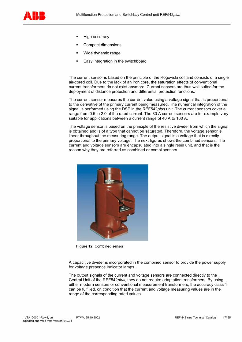
The voltage sensor is based on the principle of the resistive divider from which the signal is obtained and is of a type that cannot be saturated. Therefore, the voltage sensor is linear throughout the measuring range. The output signal is a voltage that is directly proportional to the primary voltage. The next figures shows the combined sensors. The current and voltage sensors are encapsulated into a single resin unit, and that is the reason why they are referred as combined or combi sensors.
Figure 12: Combined sensor
A capacitive divider is incorporated in the combined sensor to provide the power supply for voltage presence indicator lamps.
The output signals of the current and voltage sensors are connected directly to the Central Unit of the REF542plus, they do not require adaptation transformers. By using either modern sensors or conventional measurement transformers, the accuracy class 1 can be fulfilled, on condition that the current and voltage measuring values are in the range of the corresponding rated values.
1VTA100001-Rev 6, en PTMV, 25.10.2002 REF 542 plus Technical Catalog 17/ 55 Updated and valid from version V4C01
Multifunction Protection and Switchbay Control unit REF542plus
2.9.2 Binary inputs and outputs The primary switching devices are monitored either through the auxiliary contacts or through the related sensors, which provide the status information of all the switching compartments in the switchbay. Besides that, signals coming from auxiliary components are also monitored. Consequently, at this interface the following actions are achieved:
Control and interlocking of the primary switching device in the switchbay
Control the CBs, disconnectors, earthing switches
Supervision of the spring status, of the continuity of CB open coil, the status of the switching device.
Providing output pulse signals for external energy counting systems .
Control of the disconnectors drive motors
Providing the information regarding internal failure (watchdog).
The inputs of the binary signals are isolated by an opto-coupler. In most applications, binary outputs are implemented with mechanical relays. However, in high level applications, like a switchboard in which motors are directly driven, static power outputs are required. A maximum of 3 binary I/O boards can be installed.
1VTA100001-Rev 6, en PTMV, 25.10.2002 REF 542 plus Technical Catalog 18/ 55 Updated and valid from version V4C01

Multifunction Protection and Switchbay Control unit REF542plus
3 Diagnosis and monitoring The REF542plus monitors continuosly the condition of the system, including the switching devices. Maintenance requirements can thus be adapted to the real system condition in order to reduce down times. The following table shows the parameters monitored by the REF542plus. All the parameters can also be transmitted to a central control system where they are analyzed and processed, so that the diagnostic systems can be provided with data for reliability calculation to predict the remaining service life and maintenance actions.
Type Parameters monitored
Software Diagnostic of REF 542 plus unit
Electrical Auxiliary voltage circuits Power supply to motor operators of the switching device Continuity of windings of the CB opening coil
Mechanical components State of CB operating mechanism springs Number of mechanical operations Gas pressure respectively density
Time Count of hours the switching device board in operation. Contact switching time (from closed to open) using events
1VTA100001-Rev 6, en PTMV, 25.10.2002 REF 542 plus Technical Catalog 19/ 55 Updated and valid from version V4C01

Multifunction Protection and Switchbay Control unit REF542plus
4 Analog output An optional analog output module with four configurable outputs can be inserted in the Central Unit. The output signal of this module can be set in the range from 0 to 20 mA or 4 to 20 mA. Each of the four channels can be independently activated and parameterized by the configuration software. The following analog output quantities are selectable:
All voltage quantities directly from the analog inputs
All current quantities directly from the analog inputs
Calculated residual currents
Calculated residual voltages
Calculated apparent, active and reactive power
Calculated power factor
1VTA100001-Rev 6, en PTMV, 25.10.2002 REF 542 plus Technical Catalog 20/ 55 Updated and valid from version V4C01
Multifunction Protection and Switchbay Control unit REF542plus
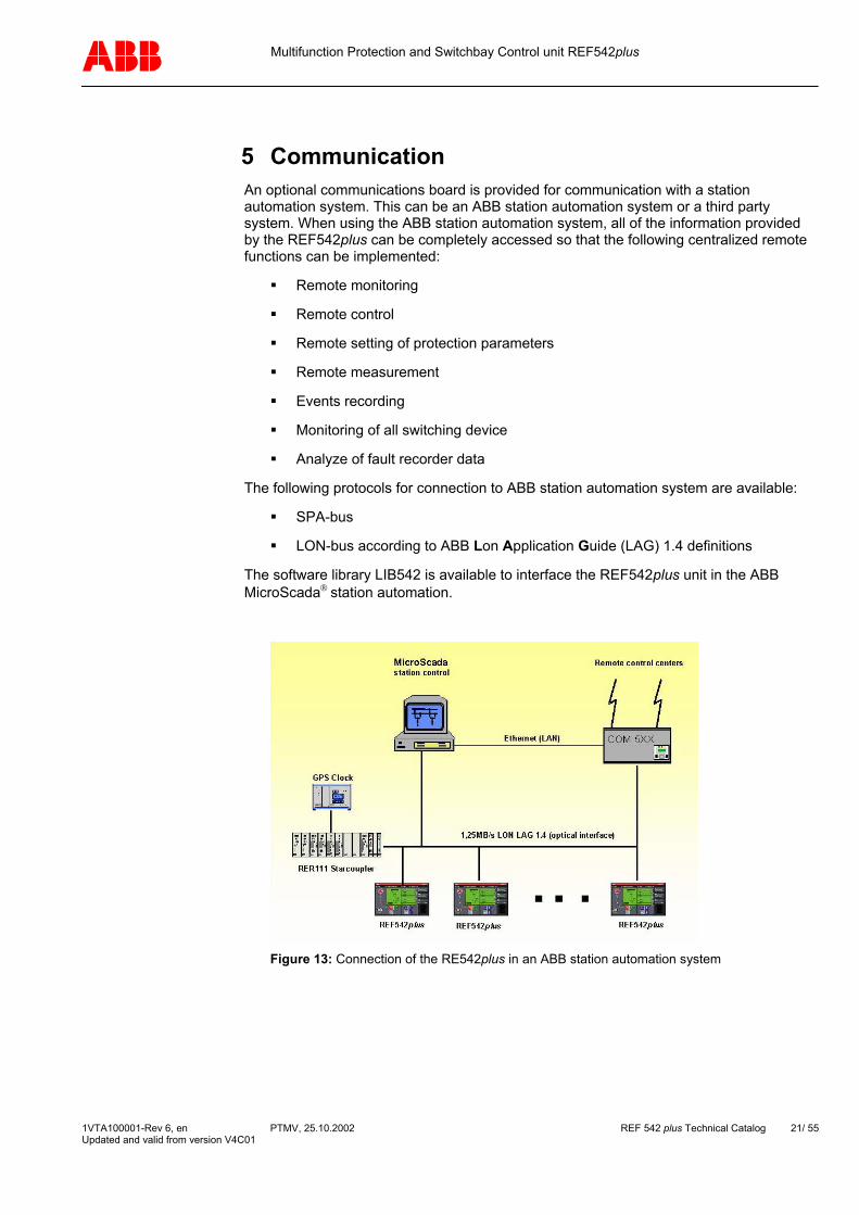
5 Communication An optional communications board is provided for communication with a station automation system. This can be an ABB station automation system or a third party system. When using the ABB station automation system, all of the information provided by the REF542plus can be completely accessed so that the following centralized remote functions can be implemented:
Remote monitoring
Remote control
Remote setting of protection parameters
Remote measurement
Events recording
Monitoring of all switching device
Analyze of fault recorder data
The following protocols for connection to ABB station automation system are available:
SPA-bus
LON-bus according to ABB Lon Application Guide (LAG) 1.4 definitions
The software library LIB542 is available to interface the REF542plus unit in the ABB MicroScada station automation.
Figure 13: Connection of the RE542plus in an ABB station automation system
1VTA100001-Rev 6, en PTMV, 25.10.2002 REF 542 plus Technical Catalog 21/ 55 Updated and valid from version V4C01
Multifunction Protection and Switchbay Control unit REF542plus
The following protocols allow REF542 plus to be connected to any third party automation system:
IEC 60870-5-103 standard including the extension for control functions according to VDEW (Vereinigung Deutscher Elektrizitätswerke = association of German utilities)
Dual MODBUS RTU
1VTA100001-Rev 6, en PTMV, 25.10.2002 REF 542 plus Technical Catalog 22/ 55 Updated and valid from version V4C01

Multifunction Protection and Switchbay Control unit REF542plus
6 Housing The REF542plus housing for the Central Unit is made from sheet aluminium. Its exterior is chromatized both to protect the housing against corrosion and to gain the shielding against EMC disturbances. The Central Unit allows a safe integration into a switchboard. A standard and a wide case version, as shown in the following figures are available. In the standard case version, two binary I/O boards and an optional communications board can be used. The wide case version contains an additional binary I/O board and the analog output board.
Figure 14: Dimension of the standard case version
1VTA100001-Rev 6, en PTMV, 25.10.2002 REF 542 plus Technical Catalog 23/ 55 Updated and valid from version V4C01

Multifunction Protection and Switchbay Control unit REF542plus
Figure 15: Dimension of the wide case version
1VTA100001-Rev 6, en PTMV, 25.10.2002 REF 542 plus Technical Catalog 24/ 55 Updated and valid from version V4C01

Multifunction Protection and Switchbay Control unit REF542plus
The dimension of the HMI Control Unit is shown in the next figure.
Figure 16: Dimension of the HMI Control Unit
1VTA100001-Rev 6, en PTMV, 25.10.2002 REF 542 plus Technical Catalog 25/ 55 Updated and valid from version V4C01
Multifunction Protection and Switchbay Control unit REF542plus
7 Mechanical design
7.1 REF542plus standard case version: 2 I/O plug-in boards for control of up to 5 switching devices.
1 optional plug-in communication board
7.2 REF542plus wide case version: 3 I/O plug-in boards for control up to 8 switching devices (with static I/O board,
only 7 switching devices with mechanical I/O board).
1 optional plug-in board for output of 4 configurable analog signals 0 to 20 mA or 4 to 20 mA.
1 optional communication board.
7.3 Analog inputs REF542plus analog input board is available in different version and can be equipped with the following combination of input current and/or voltage transformer:
3 or 6 current transformers for phase currents
3 or 6 voltage transformers for phase voltages
1 current or voltage transformer for the residual current or voltage
1 current or voltage transformer for measurement purposes
When combined sensors are used the signals are connected by TWINCAM ST plugs.
1VTA100001-Rev 6, en PTMV, 25.10.2002 REF 542 plus Technical Catalog 26/ 55 Updated and valid from version V4C01

Multifunction Protection and Switchbay Control unit REF542plus
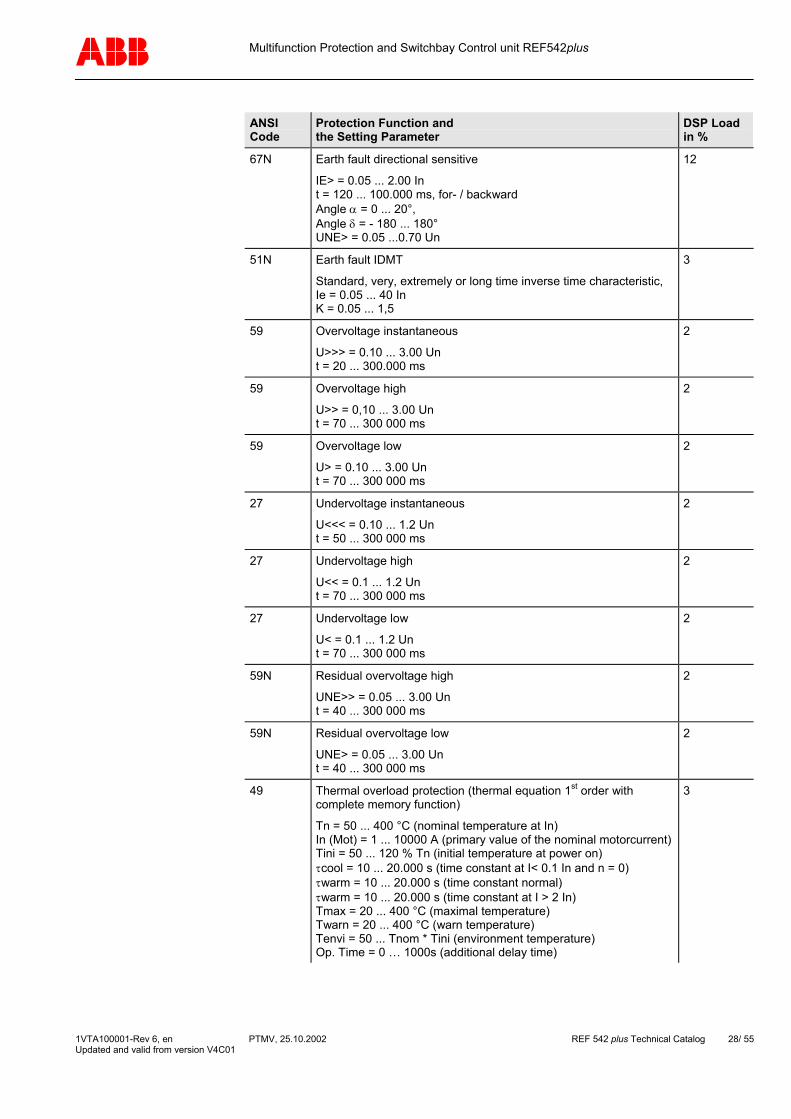
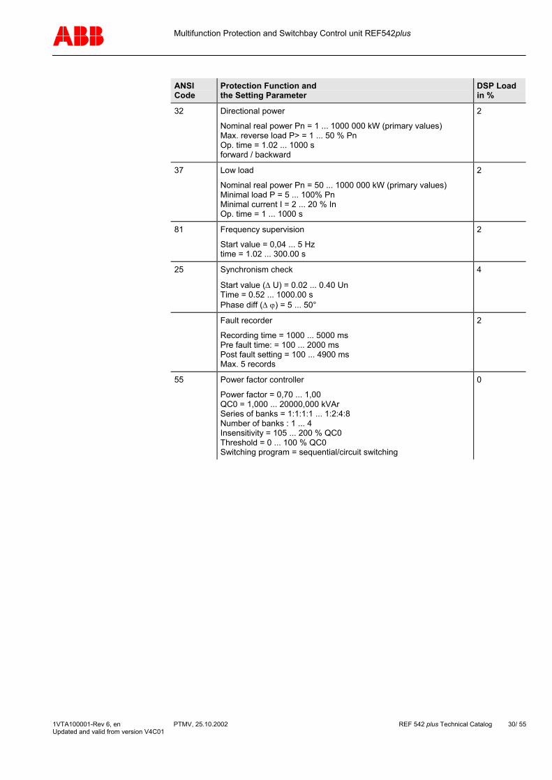
8 List of the protection functions The table below illustrates the protection functions in the current REF542plus Release 1.1. Every selected protection function increases the load on the DSP. The configuration software takes care that 100% of DSP processing power is not exceeded.
ANSI Code
Protection Function and the Setting Parameter
DSP Load in %
Digital Filtering as basic load 16
68 Inrush stabilization (Only in connection with I>> and I>)
N = 2.0 … 8.0 M = 3.0 … 4.0 Time = 220 … 100.000 ms
3
67 Overcurrent directional high
I>> = 0.05 ... 40.00 In t = 70 ... 300 000 ms
7
67 Overcurrent directional low
I > = 0.05 ... 40.00 In t = 220 ... 300 000 ms
7
50 Overcurrent instantaneous
I>>> = 0.10 ... 40.00 In t = 20 ... 300 000 ms
3
51 Overcurrent high
I>> = 0.05 ... 40.00 In t = 40 ... 300 000 ms
2
51 Overcurrent low
I > = 0.05 ... 40.00 In t = 40 ... 300 000 ms
2
51 IDMT
Normal-, Very-, Extremely- or Longtime- inverse time characteristicIe = 0.05 ... 40.00 In K = 0.05 ... 1.5
3
51N Earth fault high
IE>> = 0.05 ... 40.00 In t = 70 ... 100 000 ms
3
51N Earth fault low
IE> = 0.05 ... 40.00 In t = 70 ... 100 000 ms
3
67N Earth fault directional high
IE>> = 0.05 ... 40.00 In t = 40 ... 100 000 ms forward- / backward direction isolated (sin ϕ) and earthed (cos ϕ)
3
67N Earth fault directional low
IE> = 0.05 ... 40.00 In t = 40 ... 300 000 ms forward- / backward direction isolated (sin ϕ) and earthed (cos ϕ)
3
1VTA100001-Rev 6, en PTMV, 25.10.2002 REF 542 plus Technical Catalog 27/ 55 Updated and valid from version V4C01
Multifunction Protection and Switchbay Control unit REF542plus
ANSI Code
Protection Function and the Setting Parameter
DSP Load in %
67N Earth fault directional sensitive
IE> = 0.05 ... 2.00 In t = 120 ... 100.000 ms, for- / backward Angle α = 0 ... 20°, Angle δ = - 180 ... 180° UNE> = 0.05 ...0.70 Un
12
51N Earth fault IDMT
Standard, very, extremely or long time inverse time characteristic, Ie = 0.05 ... 40 In K = 0.05 ... 1,5
3
59 Overvoltage instantaneous
U>>> = 0.10 ... 3.00 Un t = 20 ... 300.000 ms
2
59 Overvoltage high
U>> = 0,10 ... 3.00 Un t = 70 ... 300 000 ms
2
59 Overvoltage low
U> = 0.10 ... 3.00 Un t = 70 ... 300 000 ms
2
27 Undervoltage instantaneous
U<<< = 0.10 ... 1.2 Un t = 50 ... 300 000 ms
2
27 Undervoltage high
U<< = 0.1 ... 1.2 Un t = 70 ... 300 000 ms
2
27 Undervoltage low
U< = 0.1 ... 1.2 Un t = 70 ... 300 000 ms
2
59N Residual overvoltage high
UNE>> = 0.05 ... 3.00 Un t = 40 ... 300 000 ms
2
59N Residual overvoltage low
UNE> = 0.05 ... 3.00 Un t = 40 ... 300 000 ms
2
49 Thermal overload protection (thermal equation 1st order with complete memory function)
Tn = 50 ... 400 °C (nominal temperature at In) In (Mot) = 1 ... 10000 A (primary value of the nominal motorcurrent)Tini = 50 ... 120 % Tn (initial temperature at power on) τcool = 10 ... 20.000 s (time constant at I< 0.1 In and n = 0) τwarm = 10 ... 20.000 s (time constant normal) τwarm = 10 ... 20.000 s (time constant at I > 2 In) Tmax = 20 ... 400 °C (maximal temperature) Twarn = 20 ... 400 °C (warn temperature) Tenvi = 50 ... Tnom * Tini (environment temperature) Op. Time = 0 … 1000s (additional delay time)
3
1VTA100001-Rev 6, en PTMV, 25.10.2002 REF 542 plus Technical Catalog 28/ 55 Updated and valid from version V4C01
Multifunction Protection and Switchbay Control unit REF542plus
ANSI Code
Protection Function and the Setting Parameter
DSP Load in %
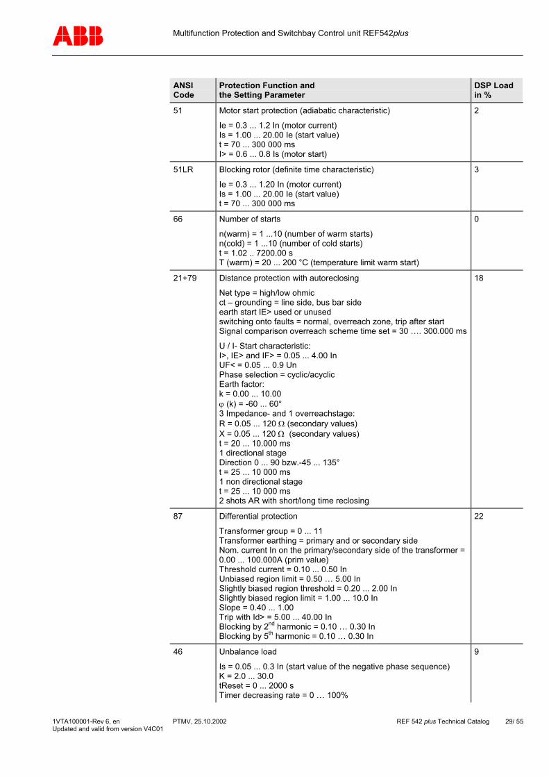
51 Motor start protection (adiabatic characteristic)
Ie = 0.3 ... 1.2 In (motor current) Is = 1.00 ... 20.00 Ie (start value) t = 70 ... 300 000 ms I> = 0.6 ... 0.8 Is (motor start)
2
51LR Blocking rotor (definite time characteristic)
Ie = 0.3 ... 1.20 In (motor current) Is = 1.00 ... 20.00 Ie (start value) t = 70 ... 300 000 ms
3
66 Number of starts
n(warm) = 1 ...10 (number of warm starts) n(cold) = 1 ...10 (number of cold starts) t = 1.02 .. 7200.00 s T (warm) = 20 ... 200 °C (temperature limit warm start)
0
21+79 Distance protection with autoreclosing
Net type = high/low ohmic ct – grounding = line side, bus bar side earth start IE> used or unused switching onto faults = normal, overreach zone, trip after start Signal comparison overreach scheme time set = 30 …. 300.000 ms
U / I- Start characteristic: I>, IE> and IF> = 0.05 ... 4.00 In UF< = 0.05 ... 0.9 Un Phase selection = cyclic/acyclic Earth factor: k = 0.00 ... 10.00 ϕ (k) = -60 ... 60° 3 Impedance- and 1 overreachstage: R = 0.05 ... 120 Ω (secondary values) X = 0.05 ... 120 Ω (secondary values) t = 20 ... 10.000 ms 1 directional stage Direction 0 ... 90 bzw.-45 ... 135° t = 25 ... 10 000 ms 1 non directional stage t = 25 ... 10 000 ms 2 shots AR with short/long time reclosing
18
87 Differential protection
Transformer group = 0 ... 11 Transformer earthing = primary and or secondary side Nom. current In on the primary/secondary side of the transformer = 0.00 ... 100.000A (prim value) Threshold current = 0.10 ... 0.50 In Unbiased region limit = 0.50 … 5.00 In Slightly biased region threshold = 0.20 ... 2.00 In Slightly biased region limit = 1.00 ... 10.0 In Slope = 0.40 ... 1.00 Trip with Id> = 5.00 ... 40.00 In Blocking by 2nd harmonic = 0.10 … 0.30 In Blocking by 5th harmonic = 0.10 … 0.30 In
22
46 Unbalance load
Is = 0.05 ... 0.3 In (start value of the negative phase sequence) K = 2.0 ... 30.0 tReset = 0 ... 2000 s Timer decreasing rate = 0 … 100%
9
1VTA100001-Rev 6, en PTMV, 25.10.2002 REF 542 plus Technical Catalog 29/ 55 Updated and valid from version V4C01
Multifunction Protection and Switchbay Control unit REF542plus
ANSI Code
Protection Function and the Setting Parameter
DSP Load in %
32 Directional power
Nominal real power Pn = 1 ... 1000 000 kW (primary values) Max. reverse load P> = 1 ... 50 % Pn Op. time = 1.02 ... 1000 s forward / backward
2
37 Low load
Nominal real power Pn = 50 ... 1000 000 kW (primary values) Minimal load P = 5 ... 100% Pn Minimal current I = 2 ... 20 % In Op. time = 1 ... 1000 s
2
81 Frequency supervision
Start value = 0,04 ... 5 Hz time = 1.02 ... 300.00 s
2
25 Synchronism check
Start value (∆ U) = 0.02 ... 0.40 Un Time = 0.52 ... 1000.00 s Phase diff (∆ ϕ) = 5 ... 50°
4
Fault recorder
Recording time = 1000 ... 5000 ms Pre fault time: = 100 ... 2000 ms Post fault setting = 100 ... 4900 ms Max. 5 records
2
55 Power factor controller
Power factor = 0,70 ... 1,00 QC0 = 1,000 ... 20000,000 kVAr Series of banks = 1:1:1:1 ... 1:2:4:8 Number of banks : 1 ... 4 Insensitivity = 105 ... 200 % QC0 Threshold = 0 ... 100 % QC0 Switching program = sequential/circuit switching
0
1VTA100001-Rev 6, en PTMV, 25.10.2002 REF 542 plus Technical Catalog 30/ 55 Updated and valid from version V4C01
Multifunction Protection and Switchbay Control unit REF542plus
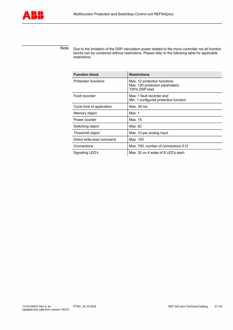
Note Due to the limitation of the DSP calculation power related to the micro controller not all function blocks can be combined without restrictions. Please refer to the following table for applicable restrictions.
Function block Restrictions
Protection functions Max. 12 protection functions Max. 120 protection parameters 100% DSP load
Fault recorder Max. 1 fault recorder and Min. 1 configured protection function
Cycle time of application Max. 30 ms
Memory object Max. 1
Power counter Max. 15
Switching object Max. 62
Threshold object Max. 10 per analog input
Direct write-read command Max. 100
Connections Max. 700, number of connections 512
Signaling LED's Max. 32 on 4 sides of 8 LED's each
1VTA100001-Rev 6, en PTMV, 25.10.2002 REF 542 plus Technical Catalog 31/ 55 Updated and valid from version V4C01

Multifunction Protection and Switchbay Control unit REF542plus
9 Technical data
9.1 Analog input channels Accuracy for measurement: Class 1 Accuracy for protection applications: Class 3 Accuracy of the protection operation time min. ± 20ms or Class 3
9.1.1 Current and voltage transformer input values
Rated current In 1A or 5A
Rated voltage Un 100V (also suitable for 110V)
Rated frequency fn 50 Hz / 60 Hz
Thermal load capacity Current path 250 In (peak value) dynamic,
100 In for 1s, 4 In continuous,
Voltage path 2 Un /√3 continuous.
Consumption Current path ≤ 0.1 VA with In
Voltage path ≤ 0.25 VA with Un
9.1.2 Current and voltage sensor input values
Voltage at rated current In 150 mV (rms)
Voltage at rated voltage Un 2V (rms)
Rated frequency fn 50 Hz / 60 Hz
1VTA100001-Rev 6, en PTMV, 25.10.2002 REF 542 plus Technical Catalog 32/ 55 Updated and valid from version V4C01

Multifunction Protection and Switchbay Control unit REF542plus
9.2 Binary inputs and outputs Each Binary I/O module has the following number of inputs and outputs:
9.2.1 BIO module with mechanical output relays (version 3)
14 input channels Possible auxiliary voltage ranges:
• 20 to 90 V DC (threshold 14 V DC)
• 80 to 250 V DC (threshold 50 V DC)
Each input has a minimum fixed filter time of 1 ms. Additional filter time can be configured.
6 power outputs (channels BO 1 to 6).
Maximum operating voltage 250V AC/DC Make current 20 A Load current 12 A Breaking capacity 300 W at L/R <15 ms Operating time 6 ms
2 signal outputs (BO7 and 8) and 1 Watchdog output (WD)
Maximum operating voltage 250 V AC/DC Make current 8A Load current 2 A Breaking capacity 90W at L/R <10ms Operating time 5 ms
Optional: 1 Static signal output on BO7
Maximum operating voltage 250 VDC Make current 1.5 A peak Load current 0.7 A continuous Breaking capacity 62W at L/R <3 ms Operating time 1 ms
1 coil supervision circuit for channel BO2
1VTA100001-Rev 6, en PTMV, 25.10.2002 REF 542 plus Technical Catalog 33/ 55 Updated and valid from version V4C01
Multifunction Protection and Switchbay Control unit REF542plus
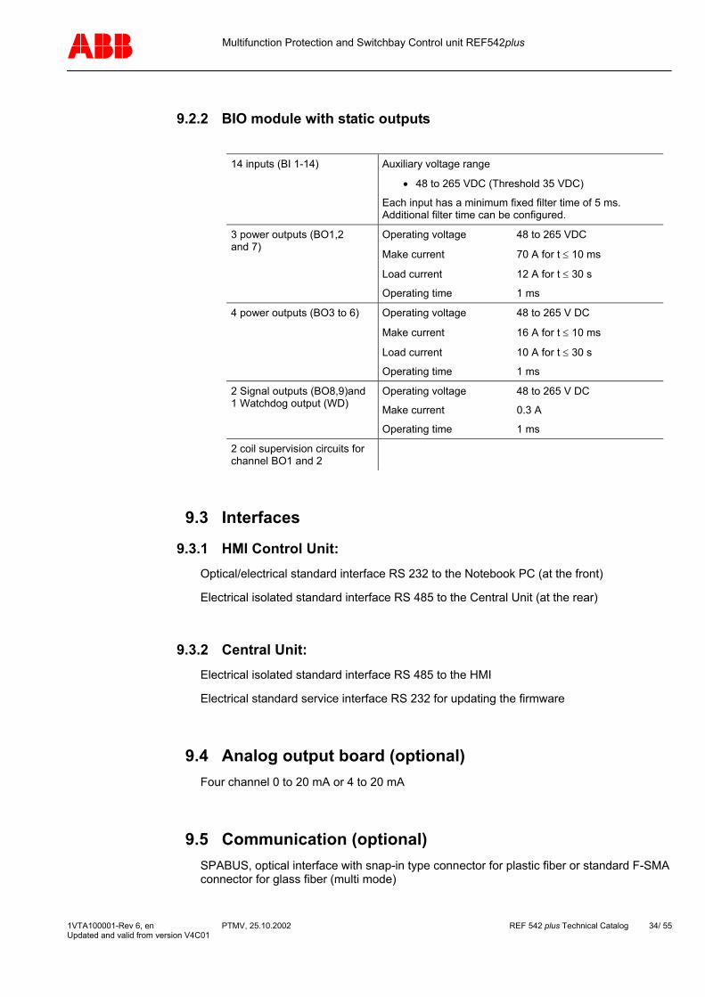
9.2.2 BIO module with static outputs
14 inputs (BI 1-14) Auxiliary voltage range
• 48 to 265 VDC (Threshold 35 VDC)
Each input has a minimum fixed filter time of 5 ms. Additional filter time can be configured.
3 power outputs (BO1,2 and 7)
Operating voltage 48 to 265 VDC
Make current 70 A for t ≤ 10 ms
Load current 12 A for t ≤ 30 s
Operating time 1 ms
4 power outputs (BO3 to 6) Operating voltage 48 to 265 V DC
Make current 16 A for t ≤ 10 ms
Load current 10 A for t ≤ 30 s
Operating time 1 ms
2 Signal outputs (BO8,9)and 1 Watchdog output (WD)
Operating voltage 48 to 265 V DC
Make current 0.3 A
Operating time 1 ms
2 coil supervision circuits for channel BO1 and 2
9.3 Interfaces
9.3.1 HMI Control Unit: Optical/electrical standard interface RS 232 to the Notebook PC (at the front)
Electrical isolated standard interface RS 485 to the Central Unit (at the rear)
9.3.2 Central Unit: Electrical isolated standard interface RS 485 to the HMI
Electrical standard service interface RS 232 for updating the firmware
9.4 Analog output board (optional) Four channel 0 to 20 mA or 4 to 20 mA
9.5 Communication (optional) SPABUS, optical interface with snap-in type connector for plastic fiber or standard F-SMA connector for glass fiber (multi mode)
1VTA100001-Rev 6, en PTMV, 25.10.2002 REF 542 plus Technical Catalog 34/ 55 Updated and valid from version V4C01

Multifunction Protection and Switchbay Control unit REF542plus
LON (according to ABB LAG1.4), optical interface with ST connector for glass fiber (multi mode)
IEC 60870-5-103 with extension according to VDEW guidelines for controlling, optical interface with ST connector for glass fiber (multi mode)
Dual MODBUS RTU, electrical interface with two RS485 ports or optical interface with two standard ST connector for glass fiber (multi mode)
9.6 Power supply
9.6.1 Central Unit
Rated voltage 110 VDC (-15%, +10%), 220 VDC (-15%, +10%) or 48 to 220 VDC (-15%, +10%)
Power consumption ≤ 18 W (base version with 1 BIO)
Inrush current ≤ 10 A peak value
9.6.2 HMI Control Unit
Rated voltage: For auxiliary voltage in the range of:
• 48 … 110 VDC (-15%, +10%)
• 110 … 220 VDC (-15%, +10%)
Power consumption ≤ 6 W
9.7 Environmental conditions
Ambient operation temperature -5 ..+ 55°C
Ambient transport and storage temperature
-20..+70°C
Ambient humidity Up to 95% without condensation
1VTA100001-Rev 6, en PTMV, 25.10.2002 REF 542 plus Technical Catalog 35/ 55 Updated and valid from version V4C01
Multifunction Protection and Switchbay Control unit REF542plus
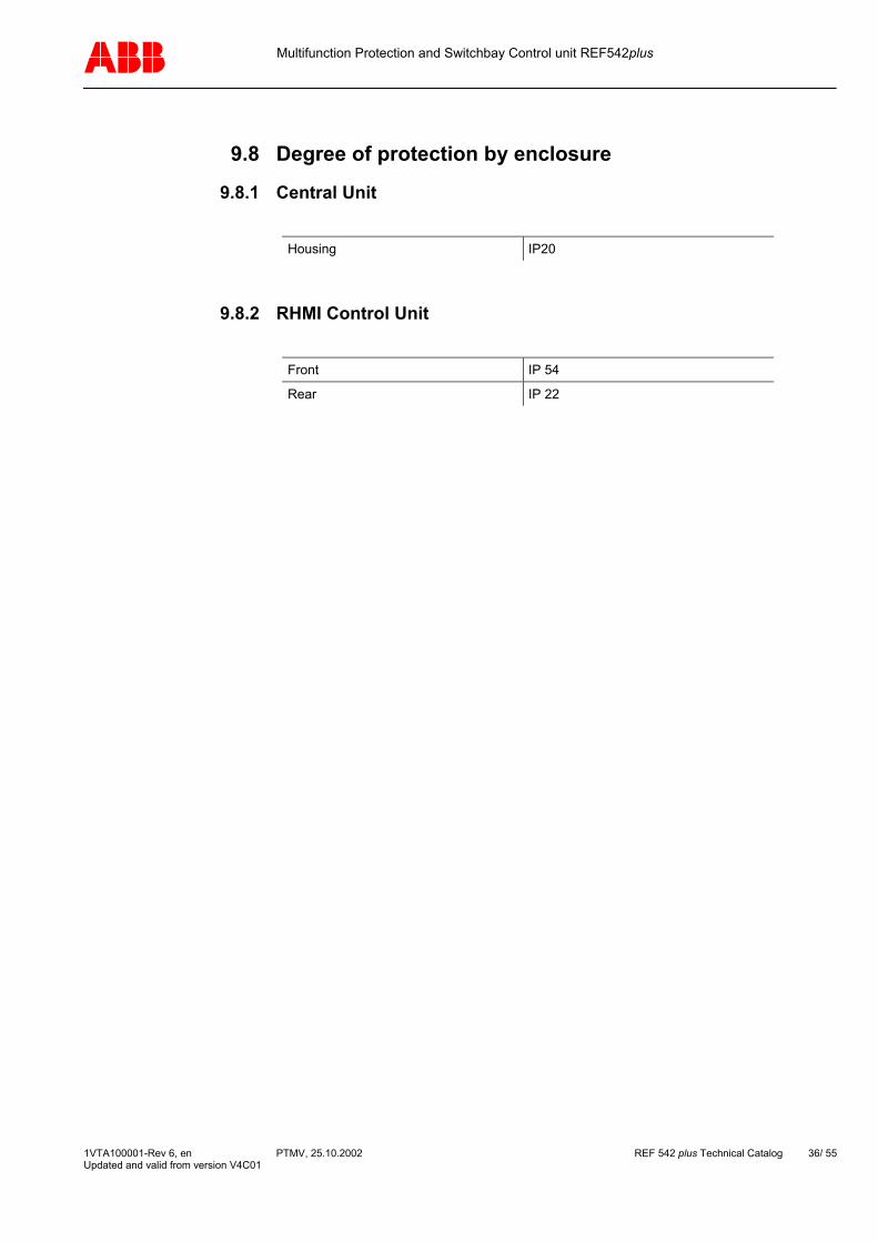
9.8 Degree of protection by enclosure
9.8.1 Central Unit
Housing IP20
9.8.2 RHMI Control Unit
Front IP 54
Rear IP 22
1VTA100001-Rev 6, en PTMV, 25.10.2002 REF 542 plus Technical Catalog 36/ 55 Updated and valid from version V4C01
Multifunction Protection and Switchbay Control unit REF542plus
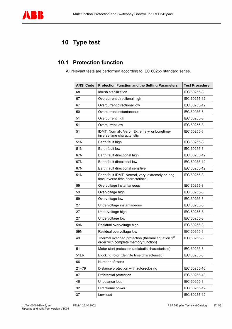
10 Type test
10.1 Protection function All relevant tests are performed according to IEC 60255 standard series.
ANSI Code Protection Function and the Setting Parameters Test Procedure
68 Inrush stabilization IEC 60255-3
67 Overcurrent directional high IEC 60255-12
67 Overcurrent directional low IEC 60255-12
50 Overcurrent instantaneous IEC 60255-3
51 Overcurrent high IEC 60255-3
51 Overcurrent low IEC 60255-3
51 IDMT, Normal-, Very-, Extremely- or Longtime- inverse time characteristic
IEC 60255-3
51N Earth fault high IEC 60255-3
51N Earth fault low IEC 60255-3
67N Earth fault directional high IEC 60255-12
67N Earth fault directional low IEC 60255-12
67N Earth fault directional sensitive IEC 60255-12
51N Earth fault IDMT, Normal, very, extremely or long time inverse time characteristic,
IEC 60255-3
59 Overvoltage instantaneous IEC 60255-3
59 Overvoltage high IEC 60255-3
59 Overvoltage low IEC 60255-3
27 Undervoltage instantaneous IEC 60255-3
27 Undervoltage high IEC 60255-3
27 Undervoltage low IEC 60255-3
59N Residual overvoltage high IEC 60255-3
59N Residual overvoltage low IEC 60255-3
49 Thermal overload protection (thermal equation 1st order with complete memory function)
IEC 60255-8
51 Motor start protection (adiabatic characteristic) IEC 60255-3
51LR Blocking rotor (definite time characteristic) IEC 60255-3
66 Number of starts
21+79 Distance protection with autoreclosing IEC 60255-16
87 Differential protection IEC 60255-13
46 Unbalance load IEC 60255-3
32 Directional power IEC 60255-12
37 Low load IEC 60255-12
1VTA100001-Rev 6, en PTMV, 25.10.2002 REF 542 plus Technical Catalog 37/ 55 Updated and valid from version V4C01
Multifunction Protection and Switchbay Control unit REF542plus
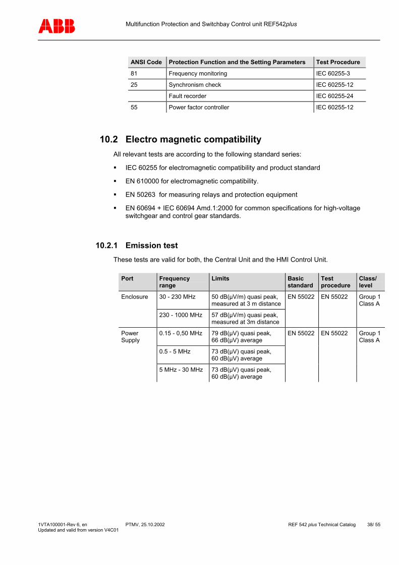
ANSI Code Protection Function and the Setting Parameters Test Procedure
81 Frequency monitoring IEC 60255-3
25 Synchronism check IEC 60255-12
Fault recorder IEC 60255-24
55 Power factor controller IEC 60255-12
10.2 Electro magnetic compatibility All relevant tests are according to the following standard series:
IEC 60255 for electromagnetic compatibility and product standard
EN 610000 for electromagnetic compatibility.
EN 50263 for measuring relays and protection equipment
EN 60694 + IEC 60694 Amd.1:2000 for common specifications for high-voltage switchgear and control gear standards.
10.2.1 Emission test These tests are valid for both, the Central Unit and the HMI Control Unit.
Port Frequency
range Limits Basic
standard Test procedure
Class/ level
Enclosure 30 - 230 MHz 50 dB(µV/m) quasi peak, measured at 3 m distance
EN 55022 EN 55022
Group 1 Class A
230 - 1000 MHz 57 dB(µV/m) quasi peak, measured at 3m distance
Power Supply
0.15 - 0,50 MHz 79 dB(µV) quasi peak, 66 dB(µV) average
EN 55022 EN 55022
Group 1 Class A
0.5 - 5 MHz 73 dB(µV) quasi peak, 60 dB(µV) average
5 MHz - 30 MHz 73 dB(µV) quasi peak, 60 dB(µV) average
1VTA100001-Rev 6, en PTMV, 25.10.2002 REF 542 plus Technical Catalog 38/ 55 Updated and valid from version V4C01
Multifunction Protection and Switchbay Control unit REF542plus
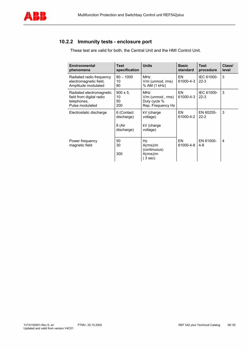
10.2.2 Immunity tests - enclosure port These test are valid for both, the Central Unit and the HMI Control Unit.
Environmental phenomena
Test specification
Units Basic standard
Test procedure
Class/ level
Radiated radio frequency electromagnetic field, Amplitude modulated
80 – 1000 10 80
MHz V/m (unmod, rms) % AM (1 kHz)
EN 61000-4-3
IEC 61000-22-3
3
Radiated electromagnetic field from digital radio telephones, Pulse modulated
900 ± 5, 10 50 200
MHz V/m (unmod., rms)Duty cycle % Rep. Frequency Hz
EN 61000-4-3
IEC 61000-22-3
3
Electrostatic discharge 6 (Contact discharge) 8 (Air discharge)
kV (charge voltage) kV (charge voltage)
EN 61000-4-2
EN 60255-22-2
3
Power frequency magnetic field
50 30 300
Hz A(rms)/m (continuous) A(rms)/m ( 3 sec)
EN 61000-4-8
EN 61000-4-8
4
1VTA100001-Rev 6, en PTMV, 25.10.2002 REF 542 plus Technical Catalog 39/ 55 Updated and valid from version V4C01

Multifunction Protection and Switchbay Control unit REF542plus
10.2.3 Immunity tests - power supply port These test are valid for both, the Central Unit and the HMI Control Unit.
Environmental phenomena
Test specification
Units Basic standard
Test procedure
Class/ Level
Conducted disturbance induced by radio-frequency fields, amplitude modulated
0,15 – 80 10 80 150
MHz V (unmod., rms) % AM (1 kHz) ohms Source impedance
EN 61000-4-6
IEC 60255-22-6 and IEC 60694
3
Fast transients 5/50 5 2
Tr/Th ns kHz repetition frequency kV (peak)
EN 61000-4-4
IEC 60255-22-4 and IEC 60694
4
1 MHz burst Differential mode Common mode
1 75 400 200 1 2,5
MHz frequency Tr ns Hz repetition frequency ohms Source impedance kV (peak) kV (peak)
EN 61000-4-12
IEC 60255-22-1 and IEC 60694
3
Surge Differential mode Common mode source
1,2/50 (8/20)1 2 12
Tr/Th us kV charge voltage kV charge voltage ohms Source impedance
EN 61000-4-5
EN 61000-4-5
3
Voltage Interruption
100 50
% reduction ms interruption time
EN 61000-4-29
IEC 60255-11
3
Voltage Ripple
10 % of d.c. component
EN 61000-4-17
IEC 60694 2
Insulation
Central unit
2 or 3 5
kV/AC 1 Minute kV/DC 1 Minute kV impulse 1,2/50us; 0.5J
IEC60255-5
IEC60255-5
Insulation
HMI control unit
2 or 3 4
kV/AC 1 Minute kV/DC 1 Minute kV impulse 1,2/50us;0.5J
IEC60255-5
IEC60255-5
1VTA100001-Rev 6, en PTMV, 25.10.2002 REF 542 plus Technical Catalog 40/ 55 Updated and valid from version V4C01
Multifunction Protection and Switchbay Control unit REF542plus
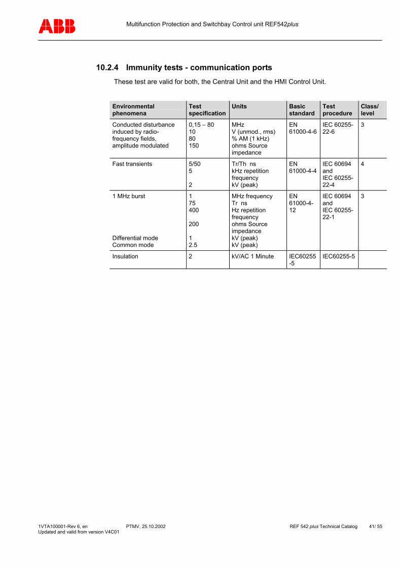
10.2.4 Immunity tests - communication ports These test are valid for both, the Central Unit and the HMI Control Unit.
Environmental phenomena
Test specification
Units Basic standard
Test procedure
Class/ level
Conducted disturbance induced by radio-frequency fields, amplitude modulated
0,15 – 80 10 80 150
MHz V (unmod., rms) % AM (1 kHz) ohms Source impedance
EN 61000-4-6
IEC 60255-22-6
3
Fast transients
5/50 5 2
Tr/Th ns kHz repetition frequency kV (peak)
EN 61000-4-4
IEC 60694 and IEC 60255-22-4
4
1 MHz burst Differential mode Common mode
1 75 400 200 1 2.5
MHz frequency Tr ns Hz repetition frequency ohms Source impedance kV (peak) kV (peak)
EN 61000-4-12
IEC 60694 and IEC 60255-22-1
3
Insulation 2 kV/AC 1 Minute IEC60255-5
IEC60255-5
1VTA100001-Rev 6, en PTMV, 25.10.2002 REF 542 plus Technical Catalog 41/ 55 Updated and valid from version V4C01
Multifunction Protection and Switchbay Control unit REF542plus
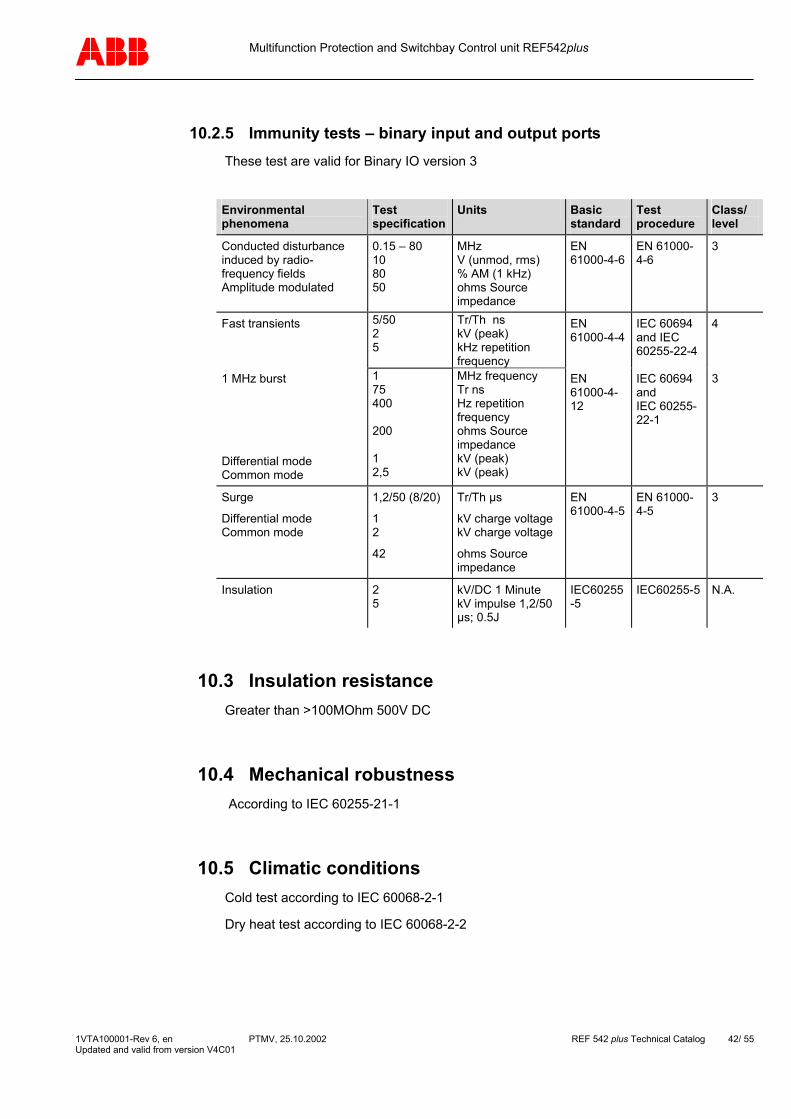
10.2.5 Immunity tests – binary input and output ports These test are valid for Binary IO version 3
Environmental phenomena
Test specification
Units Basic standard
Test procedure
Class/ level
Conducted disturbance induced by radio-frequency fields Amplitude modulated
0.15 – 80 10 80 50
MHz V (unmod, rms) % AM (1 kHz) ohms Source impedance
EN 61000-4-6
EN 61000-4-6
3
5/50 2 5
Tr/Th ns kV (peak) kHz repetition frequency
Fast transients 1 MHz burst Differential mode Common mode
1 75 400 200 1 2,5
MHz frequency Tr ns Hz repetition frequency ohms Source impedance kV (peak) kV (peak)
EN 61000-4-4 EN 61000-4-12
IEC 60694 and IEC 60255-22-4 IEC 60694 and IEC 60255-22-1
4 3
Surge
Differential mode Common mode
1,2/50 (8/20)
1 2
42
Tr/Th µs
kV charge voltage kV charge voltage
ohms Source impedance
EN 61000-4-5
EN 61000-4-5
3
Insulation 2 5
kV/DC 1 Minute kV impulse 1,2/50 µs; 0.5J
IEC60255-5
IEC60255-5 N.A.
10.3 Insulation resistance Greater than >100MOhm 500V DC
10.4 Mechanical robustness According to IEC 60255-21-1
10.5 Climatic conditions Cold test according to IEC 60068-2-1
Dry heat test according to IEC 60068-2-2
1VTA100001-Rev 6, en PTMV, 25.10.2002 REF 542 plus Technical Catalog 42/ 55 Updated and valid from version V4C01
Multifunction Protection and Switchbay Control unit REF542plus
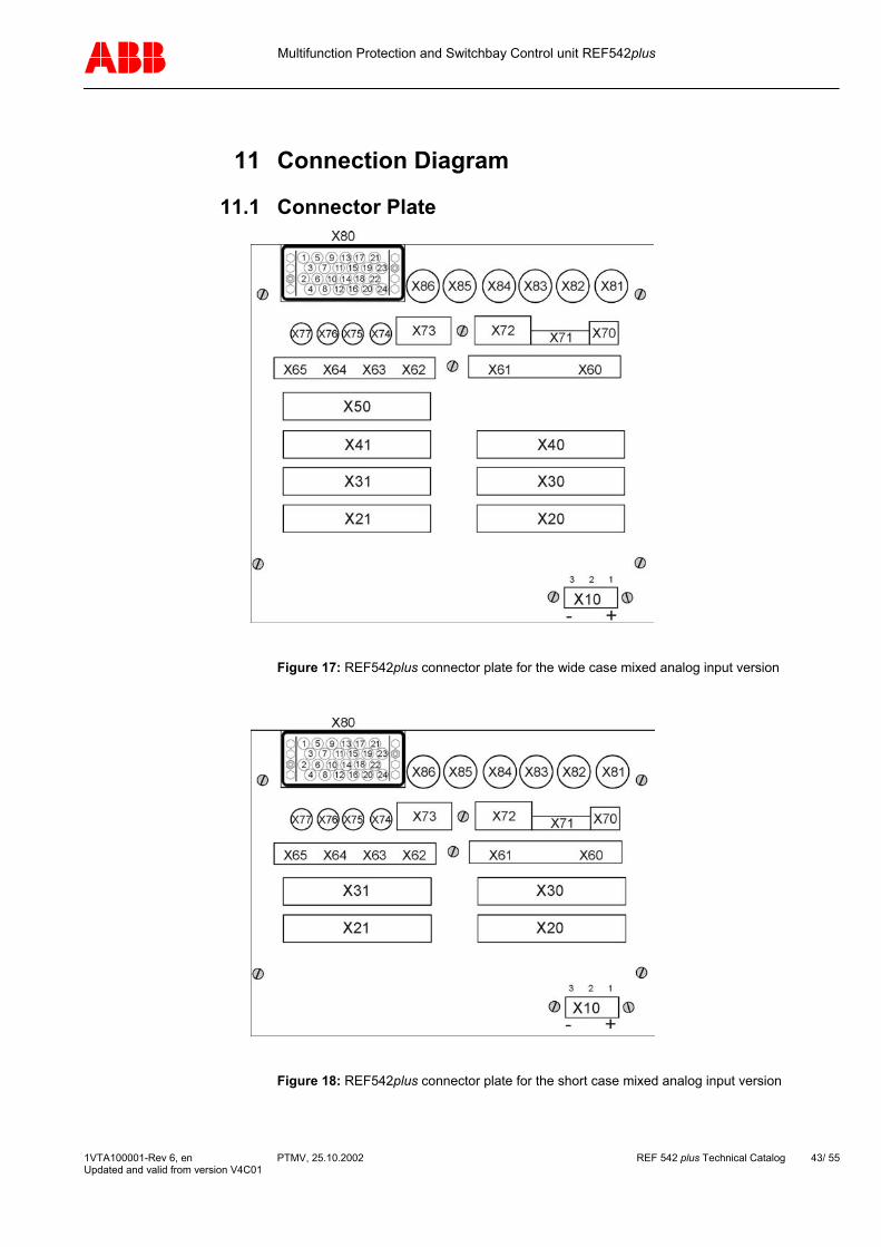
11 Connection Diagram
11.1 Connector Plate
Figure 17: REF542plus connector plate for the wide case mixed analog input version
Figure 18: REF542plus connector plate for the short case mixed analog input version
1VTA100001-Rev 6, en PTMV, 25.10.2002 REF 542 plus Technical Catalog 43/ 55 Updated and valid from version V4C01
Multifunction Protection and Switchbay Control unit REF542plus
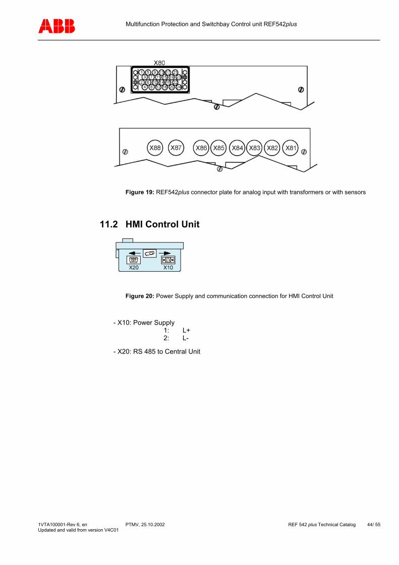
Figure 19: REF542plus connector plate for analog input with transformers or with sensors
11.2 HMI Control Unit
Figure 20: Power Supply and communication connection for HMI Control Unit
- X10: Power Supply 1: L+ 2: L-
- X20: RS 485 to Central Unit
1VTA100001-Rev 6, en PTMV, 25.10.2002 REF 542 plus Technical Catalog 44/ 55 Updated and valid from version V4C01

Multifunction Protection and Switchbay Control unit REF542plus
11.3 REF542plus with mechanical binary I/O Example of REF542plus base version with one mechanical binary I/O version 3 (BIO3). Extension up to two additional mechanical binary I/O version 3 (BIO3) possible. Other configurations of the analog input board available, e.g. mixed configuration for input transformers and sensors connection.
Note: Please connect the right polarity on binary output BO02.
DC
DC
+ -1 2 3-X10:
z28d26d28
d24z24z26BO07
BO08
BO05
BO06
d18d20
z18d22
z22
z14z16
BO04d14d16
z10z12
BO03d10d12
d06d08
BO02z06z08
d02d04
BO01z02z04
d02z02 BI01
d04z04 BI02
d06z06 BI03
d08z08 BI04
d10z10 BI05
d12z12 BI06
d14z14 BI07
d16z16 BI08
d18z18 BI09
d20z20 BI10
d22z22 BI11
d24z24 BI12
d26z26 BI13
d28z28 BI14
-X21:-X20:
+-+-+-
+-+
-+-+-+-+-+-+-+-+-+-
-
+
z20
REF542plusBase version withbinary I/O version 3
d30z30z32
WD1
-X80:
1A5A
AI 02
1A5A
AI 07
AI 06
AI 05
AI 04
1A5A
AI 03
100/110V100/110V
100/110V
100/110V
110703221814
060221170501
1923
10
241620
1A5A
AI 01T1
T2
T3
T4
T4
T6
T7
1VTA100001-Rev 6, en PTMV, 25.10.2002 REF 542 plus Technical Catalog 45/ 55 Updated and valid from version V4C01

Multifunction Protection and Switchbay Control unit REF542plus
Extension with second additional mechanical binary I/O version 3 (BIO3)
d30z30z32
z28d26d28
d24z24z26BO15
BO16
WD2
BO13
BO14
d18d20
z18d22
z22
z14z16
BO12d14d16
z10z12
BO11d10d12
d06d08
BO10z06z08
d02d04
BO09z02z04
d02z02 BI15
d04z04 BI16
d06z06 BI17
d08z08 BI18
d10z10 BI19
d12z12 BI20
d14z14 BI21
d16z16 BI22
d18z18 BI23
d20z20 BI24
d22z22 BI25
d24z24 BI26
d26z26 BI27
d28z28 BI28
-X31:-X30:+-+-+-
+-+
-+-+-+-+-+-+-+-+-+-
-
+
z20
Note: Please connect the right polarity on BO 10
1VTA100001-Rev 6, en PTMV, 25.10.2002 REF 542 plus Technical Catalog 46/ 55 Updated and valid from version V4C01
Multifunction Protection and Switchbay Control unit REF542plus
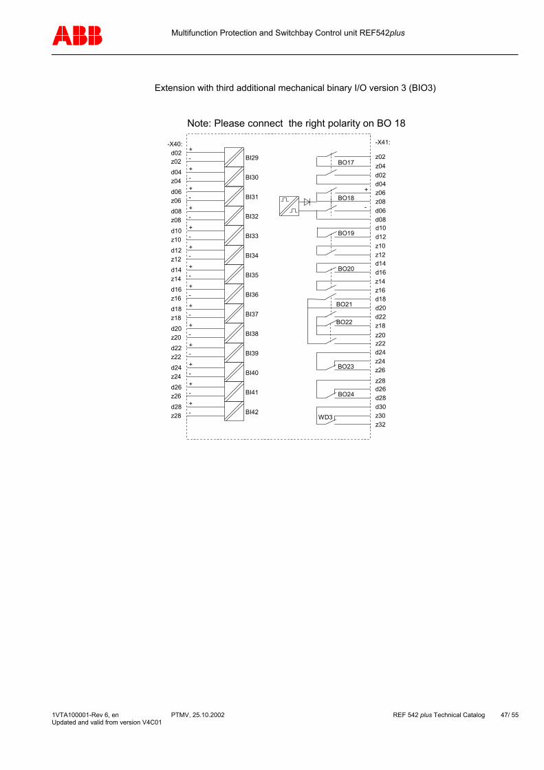
Extension with third additional mechanical binary I/O version 3 (BIO3)
d30z30z32
z28d26d28
d24z24z26BO23
BO24
WD3
BO21
BO22
d18d20
z18d22
z22
z14z16
BO20d14d16
z10z12
BO19d10d12
d06d08
BO18z06z08
d02d04
BO17z02z04
d02z02 BI29
d04z04 BI30
d06z06 BI31
d08z08 BI32
d10z10 BI33
d12z12 BI34
d14z14 BI35
d16z16 BI36
d18z18 BI37
d20z20 BI38
d22z22 BI39
d24z24 BI40
d26z26 BI41
d28z28 BI42
-X41:-X40:+-+-+-
+-+
-+-+-+-+-+-+-+-+-+-
-
+
z20
Note: Please connect the right polarity on BO 18
1VTA100001-Rev 6, en PTMV, 25.10.2002 REF 542 plus Technical Catalog 47/ 55 Updated and valid from version V4C01

Multifunction Protection and Switchbay Control unit REF542plus
11.4 REF542plus with solid state binary I/O Example of REF542plus base version for sensor connection with one solid state binary I/O. Extension up to two additional solid state binary I/O possible. Other configurations of the analog input board available, e.g. mixed configuration for input transformers and sensors connection.
Note: Please connect the right polarity
DC
DC
+ -1 2 3-X10:
-X81: AD Sensor 1
AD Sensor 2
AD Sensor 3
AD Sensor 4
AD Sensor 5
AD Sensor 6
AD Sensor 7
AD Sensor 8
-X82:
-X83:
-X84:
-X85:
-X86:
-X87:
-X88:
d30z32
z20z22z18
BO06
WD1
z10z12
BO07d10d12
d02z02 BI01
d04z04 BI02
d06z06 BI03
d08z08 BI04
d10z10 BI05
d12z12 BI06
d14z14 BI07
d16z16 BI08
d18z18 BI09
d20z20 BI10
d22z22 BI11
d24z24 BI12
d26z26 BI13
d28z28 BI14
-X21:-X20:+-+-+-
+-+
-+-+-+-+-+-+-+-+-+-
z28d28BO09
d24z26BO08
+
+
+
BO04
d18d20d22BO05
BO03+
++
+
-
z06z08
BO02d06d08
-
+
z02z04
BO01d02d04
-
+
REF542plusBase version withsensor andsolid state binary I/O
1VTA100001-Rev 6, en PTMV, 25.10.2002 REF 542 plus Technical Catalog 48/ 55 Updated and valid from version V4C01
Multifunction Protection and Switchbay Control unit REF542plus
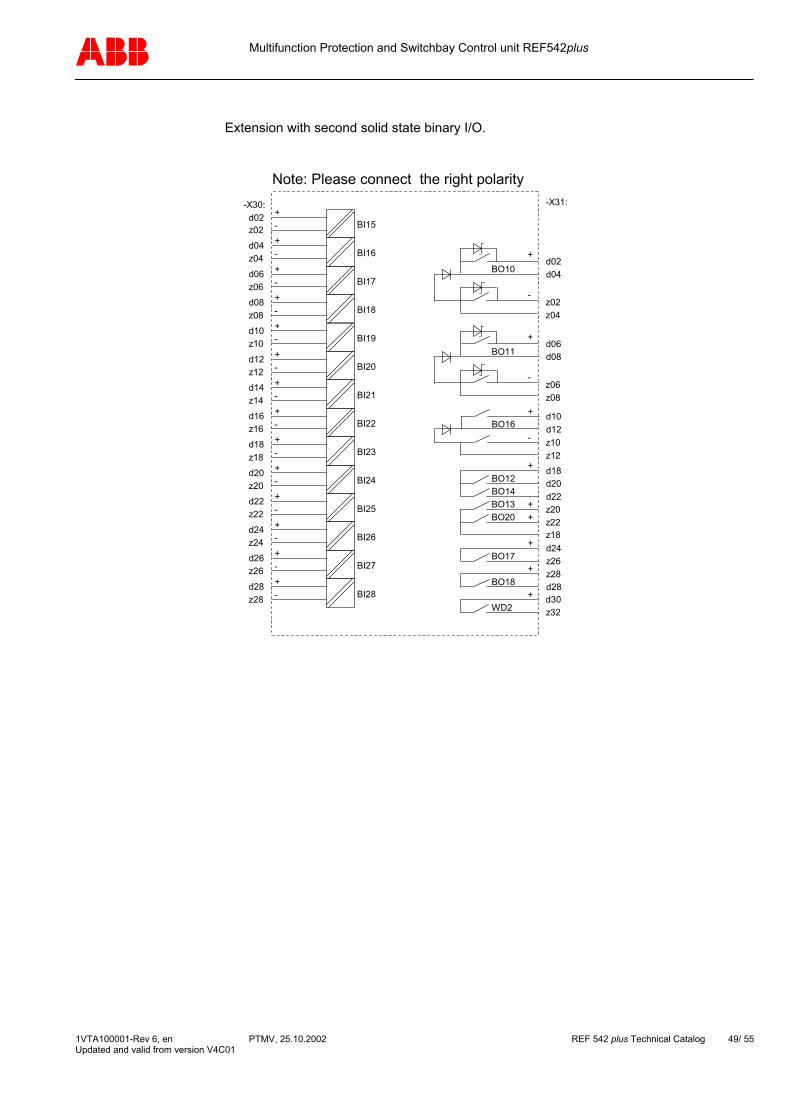
Extension with second solid state binary I/O.
d30z32
z20z22z18
BO20
WD2
z10z12
BO16d10d12
d02z02 BI15
d04z04 BI16
d06z06 BI17
d08z08 BI18
d10z10 BI19
d12z12 BI20
d14z14 BI21
d16z16 BI22
d18z18 BI23
d20z20 BI24
d22z22 BI25
d24z24 BI26
d26z26 BI27
d28z28 BI28
-X31:-X30:+-+-+-
+-+
-+-+-+-+-+-+-+-+-+-
z28d28BO18
d24z26BO17
+
+
+
BO13
d18d20d22BO14
BO12+
++
+
-
z06z08
BO11d06d08
-
+
z02z04
BO10d02d04
-
+
Note: Please connect the right polarity
1VTA100001-Rev 6, en PTMV, 25.10.2002 REF 542 plus Technical Catalog 49/ 55 Updated and valid from version V4C01
Multifunction Protection and Switchbay Control unit REF542plus
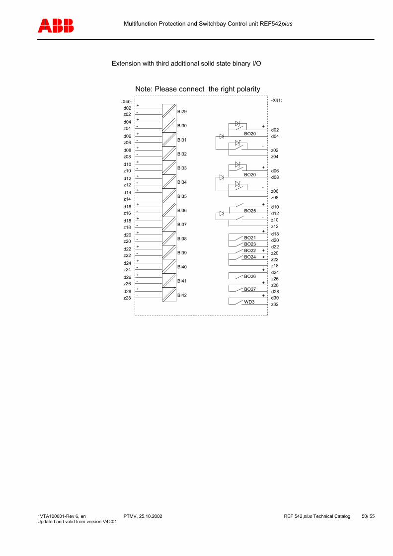
Extension with third additional solid state binary I/O
d30z32
z20z22z18
BO24
WD3
z10z12
BO25d10d12
d02z02 BI29
d04z04 BI30
d06z06 BI31
d08z08 BI32
d10z10 BI33
d12z12 BI34
d14z14 BI35
d16z16 BI36
d18z18 BI37
d20z20 BI38
d22z22 BI39
d24z24 BI40
d26z26 BI41
d28z28 BI42
-X41:-X40:+-+-+-
+-+
-+-+-+-+-+-+-+-+-+-
z28d28BO27
d24z26BO26
+
+
+
BO22
d18d20d22BO23
BO21+
++
+
-
z06z08
BO20d06d08
-
+
z02z04
BO20d02d04
-
+
Note: Please connect the right polarity
1VTA100001-Rev 6, en PTMV, 25.10.2002 REF 542 plus Technical Catalog 50/ 55 Updated and valid from version V4C01

Multifunction Protection and Switchbay Control unit REF542plus
11.5 REF542plus with mechanical binary I/O (version 2) For the time being the REF542plus can only be delivered with binary I/O version 2. Extension up to two additional mechanical binary I/O version 2 (BIO2) possible. Other configurations of the analog input board available, e.g. mixed configuration for input transformers and sensors connection.
Note: Please connect the right polarity on binary output BO01 and BO2.
DC
DC
+ -1 2 3-X10:
d30z30z32
z28d26d28
d24z24z26BO07
BO08
WD1
BO05BO06d18d20d22
z22z18
z20
z14z16
BO04d14d16
z10z12
BO03d10d12
d06d08
BO02z06z08
d02d04
BO01z02z04
d02z02 BI01
d04z04 BI02
d06z06 BI03
d08z08 BI04
d10z10 BI05
d12z12 BI06
d14z14 BI07
d16z16 BI08
d18z18 BI09
d20z20 BI10
d22z22 BI11
d24z24 BI12
d26z26 BI13
d28z28 BI14
-X21:-X20:+-+-+-
+-+
-+-+-+-+-+-+-+-+-+-
-
+
-
+
REF542plusBase version withbinary I/O version 2
110703221814
060221170501
-X80:1A5A
AI 011A5A
AI 02
AI 07
AI 06
AI 05
AI 04
1A5A
AI 03
1923
10
100/110V100/110V
100/110V
100/110V
241620
1A5A
T1
T2
T3
T4
T5
T6
T7
1VTA100001-Rev 6, en PTMV, 25.10.2002 REF 542 plus Technical Catalog 51/ 55 Updated and valid from version V4C01
Multifunction Protection and Switchbay Control unit REF542plus
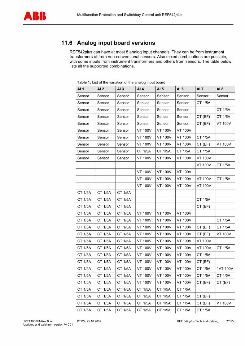
11.6 Analog input board versions REF542plus can have at most 8 analog input channels. They can be from instrument transformers of from non-conventional sensors. Also mixed combinations are possible, with some inputs from instrument transformers and others from sensors. The table below lists all the supported combinations.
Table 1: List of the variation of the analog input board
AI 1 AI 2 AI 3 AI 4 AI 5 AI 6 AI 7 AI 8
Sensor Sensor Sensor Sensor Sensor Sensor Sensor Sensor
Sensor Sensor Sensor Sensor Sensor Sensor CT 1/5A
Sensor Sensor Sensor Sensor Sensor Sensor CT 1/5A
Sensor Sensor Sensor Sensor Sensor Sensor CT (EF) CT 1/5A
Sensor Sensor Sensor Sensor Sensor Sensor CT (EF) VT 100V
Sensor Sensor Sensor VT 100V VT 100V VT 100V
Sensor Sensor Sensor VT 100V VT 100V VT 100V CT 1/5A
Sensor Sensor Sensor VT 100V VT 100V VT 100V CT (EF) VT 100V
Sensor Sensor Sensor CT 1/5A CT 1/5A CT 1/5A CT 1/5A
Sensor Sensor Sensor VT 100V VT 100V VT 100V VT 100V
VT 100V CT 1/5A
VT 100V VT 100V VT 100V
VT 100V VT 100V VT 100V VT 100V CT 1/5A
VT 100V VT 100V VT 100V VT 100V
CT 1/5A CT 1/5A CT 1/5A
CT 1/5A CT 1/5A CT 1/5A CT 1/5A
CT 1/5A CT 1/5A CT 1/5A CT (EF)
CT 1/5A CT 1/5A CT 1/5A VT 100V VT 100V VT 100V
CT 1/5A CT 1/5A CT 1/5A VT 100V VT 100V VT 100V CT 1/5A
CT 1/5A CT 1/5A CT 1/5A VT 100V VT 100V VT 100V CT (EF) CT 1/5A
CT 1/5A CT 1/5A CT 1/5A VT 100V VT 100V VT 100V CT (EF) VT 100V
CT 1/5A CT 1/5A CT 1/5A VT 100V VT 100V VT 100V VT 100V
CT 1/5A CT 1/5A CT 1/5A VT 100V VT 100V VT 100V VT 100V CT 1/5A
CT 1/5A CT 1/5A CT 1/5A VT 100V VT 100V VT 100V CT 1/5A
CT 1/5A CT 1/5A CT 1/5A VT 100V VT 100V VT 100V CT (EF)
CT 1/5A CT 1/5A CT 1/5A VT 100V VT 100V VT 100V CT 1/5A 1VT 100V
CT 1/5A CT 1/5A CT 1/5A VT 100V VT 100V VT 100V CT 1/5A CT 1/5A
CT 1/5A CT 1/5A CT 1/5A VT 100V VT 100V VT 100V CT (EF) CT (EF)
CT 1/5A CT 1/5A CT 1/5A CT 1/5A CT 1/5A CT 1/5A
CT 1/5A CT 1/5A CT 1/5A CT 1/5A CT 1/5A CT 1/5A CT (EF)
CT 1/5A CT 1/5A CT 1/5A CT 1/5A CT 1/5A CT 1/5A CT (EF) VT 100V
CT 1/5A CT 1/5A CT 1/5A CT 1/5A CT 1/5A CT 1/5A CT 1/5A
1VTA100001-Rev 6, en PTMV, 25.10.2002 REF 542 plus Technical Catalog 52/ 55 Updated and valid from version V4C01

Multifunction Protection and Switchbay Control unit REF542plus
AI 1 AI 2 AI 3 AI 4 AI 5 AI 6 AI 7 AI 8
VT 100V VT 100V VT 100V VT 100V VT 100V VT 100V
VT 100V VT 100V VT 100V VT 100V VT 100V VT 100V CT (EF) CT (EF)
VT 100V VT 100V VT 100V VT 100V VT 100V VT 100V VT 100V
CT (EF) is a special input transformer to measure the earth fault current in isolated or with Petersen coil compensated system by means of cable current transformer. For the setting of the related analog input the primary nominal current of the cable current transformer must be divided by 5.
The connections to the Compel connectors for the analog input board are shown in the next following figures. The connection of AI07 and AI08 can principally be derived, depending on the input transformer used.
110703221814
060221170501
-X80:1A5A
AI 011A5A
AI 02
AI 06
AI 05
AI 04
1A5A
AI 03
1923
10
100/110V100/110V
100/110V
100/110V
T1
T2
T3
T4
T5
T6
110703221814
0602
-X80:1A5A
AI 011A5A
AI 021A5A
AI 03
10
T1
T2
T3
21170501
-X80:
AI 06
AI 05
AI 04
1923 100/110V100/110V
100/110V
100/110VT4
T5
T6
211317050901
1519
1A5A
AI 041A5A
AI 051A5A
AI 06
23
T4
T5
T6
11032214
AI 03
AI 02
AI 01
0206 100/110V100/110V
100/110V
100/110VT1
T2
T3
Figure 21: Connections of the analog input with transformer for AI01 to AI06
-X80:
1A5A
AI 07
241620
AI 08
120408
1A5A T7
T8
2016
-X80:
AI 08
AI 07
0408 100/110V100/110V
100/110V 1620
-X80:
AI 08
AI 07
0804 CT (EF)
CT (EF)T7
T8
T7
T8
Figure 22: Connections of the analog input with transformer for AI07 to AI08
1VTA100001-Rev 6, en PTMV, 25.10.2002 REF 542 plus Technical Catalog 53/ 55 Updated and valid from version V4C01
Multifunction Protection and Switchbay Control unit REF542plus
Product Information
ABB Transmission and Distribution Limited Indoor Switchgear
Bapaume Road Moorebank NSW Australia
Phone: +61 2 9821 0007 Fax: +61 2 9602 2454 E-mail: [email protected] Internet:: http://www.abb.com
ABB Secheron SA Medium Voltage
Rue des Sablieres 4-6 CH – 1217 Meyrin Switzerland
Phone: +41 22 306 2646 Fax: +41 22 306 2682 E-mail: [email protected] Internet: http://www.abb.ch
ABB Xiamen Switchgear Co. Ltd Engineering
ABB Industrial Park, Torch Hi-Tech Indus-trial Development Zone, Xiao Dong Shan Xiamen S.E.Z., Fujian 361006 P.R. China
Phone: +86 592 6026-033 Ext. 4061 Fax: +86 592 603-0525 E-mail: [email protected]: http://www.abb.com
ABB High Voltage Switchgear Co. Ltd. MV Technical
No. 7 Shiliuzhuang Nanli, Nanding Road, Yongdingmen Wei, Fengtai District Beijing 100075 P.R. China
Phone: +86 10 6764-0055 Fax: +86 10 6766-3121 E-mail: [email protected] Internet: http://www.abb.com
ABB s.r.o. MV Switchgear
Videnska 117 61900 Brno Czech Republic
Phone: +420 5 4715 2413 Fax: +420 5 4715 2190 E-mail: [email protected] Internet: http://www.abb.com
ABB Arab Technical Marketing
Industrial Zone – B1 10th of Ramadan City Egypt
Phone: +2 15 36 1288 Fax: +2 15 36 1642 E-mail: Internet: http://www.abb.com/eg
ABB Calor Emag Hochspannung GmbH High Voltage Switchgear
Käfertalerstr. 250-256 68167 Mannheim Germany
Phone: +49 621 386 2938 Fax: +49 621 386 2909 E-mail: [email protected] Internet: http://www.abb.com/de
ABB Calor Emag Mittelspannung GmbH Product Management
Oberhausener Straße. 33 40472 Ratingen Germany
Phone: +49 2102 12 1901 Fax: +49 2102 12 1808 1901 E-mail: [email protected] Internet: http://www.abb.de/calor
ABB T&D S.p.A, Unita’ Operativa SACE T.M.S. Product Management
Via Friuli 4 I-24044 Dalmine (BG) Italy
Phone: +39 035 395 710 Fax: +39 035 395 874 E-mail: [email protected] Internet: http://www.abb.com
ABB Ltd. Power Technology Medium Voltage
513 Sungsung-dong (Chonan Foreign Invested-Enterprises Industrial Park) Chonan, Chungchong-namdo, Post 330-300 Korea
Phone: +82 41 529 2458 Fax: +82 41 529 2500 E-mail: [email protected] Internet: http://www.abb.com.kr
1VTA100001-Rev 6, en PTMV, 25.10.2002 REF 542 plus Technical Catalog 54/ 55 Updated and valid from version V4C01
Multifunction Protection and Switchbay Control unit REF542plus
1VTA100001-Rev 6, en PTMV, 25.10.2002 REF 542 plus Technical Catalog 55/ 55 Updated and valid from version V4C01
Product Information
ABB Transmission & Distribution Sdn. Bhd. Manufacturing
Lot 608, Jalan SS 13/1K 47500 Subang Jaya, Petaling Jaya Selanggor Darul Ehsan Malaysia
Phone: +603 5628 4888 Fax: E-mail: [email protected] Internet: http://www.abb.com
ABB b.v. Power Distribution
Marten Meesweg 5 3068 AV Rotterdam Netherland
Phone: +31 1 4078149 Fax: +31 10 4078576 E-mail: [email protected] Internet: http://www.abb.com
ABB Elektrik Sanayi. A.S. Design & Engineering
Organize Sanayi Bölgesi 2 Cadde: No. 16 Yukar Dudullu 81260 Istanbul Turkey
Phone: +90 216 365 2900 Fax: +90 216 365 2943 E-mail: [email protected] Internet: http://www.abb.com
ABB Utilities GmbH Product Management Protection
Kallstadter Straße 1 68309 Mannheim Germany
Phone: +49 621 381 8965 Fax: +49 621 381 8625 E-mail: [email protected] Internet: http://www.abb.de
ABB Oy Substation Automation Substation Automation Products
Muottitie 2A (P.O. Box 699) 65101 Vaasa Finnland
Phone: +358 10 22 4000 Fax: +358 10 22 41094 E-mail: [email protected] Internet: http://www.abb.com