Protection System Misoperation Reporting Procedure System Misop PRC-004-4... · While protective...
25
7/1/2016 MEMORANDUM To: Transmission Owners (TOs), Distribution Providers (DPs) that own transmission Protection System(s), and Generator Owners (GOs) From: Texas Reliability Entity, Inc. Date: July 1, 2016 Re: Protection System Misoperation Reporting Procedures Revision Texas Reliability Entity, Inc. (Texas RE) serves in two capacities in the ERCOT Region: (1) the Regional Entity for the ERCOT Region pursuant to its Amended and Restated Delegation Agreement with the North American Electric Reliability Corporation (NERC); and (2) the Reliability Monitor for the ERCOT Region pursuant to its Agreement with the Public Utility Commission of Texas (PUCT) and the Electric Reliability Council of Texas, Inc. (ERCOT), dated July 1, 2010. As the Reliability Monitor, Texas RE monitors and reports to the PUCT regarding ERCOT Market Participants’ compliance with reliability-related ERCOT Protocols, Operating Guides and Texas rules (ERCOT Regional Rules). ERCOT Operating Guide Section 6.2.3 requires: (a) documenting protective relay system Misoperations; (b) documenting Special Protection System (SPS) Misoperations; and (c) reporting of such Misoperations. This memorandum is being provided to all registered Transmission Owners (TOs), Distribution Providers (DPs) that own transmission Protection System(s), and Generator Owners (GOs) in the ERCOT Region. The attached procedure is intended to implement the NERC Section 1600 Request for Data or Information, Protection System Misoperation Data Collection, and also covers reporting Misoperation reporting requirements referenced in the ERCOT Operating Guides. This revised procedure becomes effective on July 1, 2016. Quarterly Misoperation reports will be due on the last day of the second month after each calendar quarter per the table below. All Protection System Misoperations shall be reported via the attached reporting procedure. Reporting Period Due Date January 1 through March 31 May 31 April 1 through June 30 August 31 July 1 through September 30 November 30 October 1 through December 31 February 28
-
Upload
phungkhuong -
Category
Documents
-
view
233 -
download
1
Transcript of Protection System Misoperation Reporting Procedure System Misop PRC-004-4... · While protective...

7/1/2016
MEMORANDUM
To: Transmission Owners (TOs), Distribution Providers (DPs) that own transmission
Protection System(s), and Generator Owners (GOs) From: Texas Reliability Entity, Inc. Date: July 1, 2016 Re: Protection System Misoperation Reporting Procedures Revision
Texas Reliability Entity, Inc. (Texas RE) serves in two capacities in the ERCOT Region: (1) the Regional Entity for the ERCOT Region pursuant to its Amended and Restated Delegation Agreement with the North American Electric Reliability Corporation (NERC); and (2) the Reliability Monitor for the ERCOT Region pursuant to its Agreement with the Public Utility Commission of Texas (PUCT) and the Electric Reliability Council of Texas, Inc. (ERCOT), dated July 1, 2010. As the Reliability Monitor, Texas RE monitors and reports to the PUCT regarding ERCOT Market Participants’ compliance with reliability-related ERCOT Protocols, Operating Guides and Texas rules (ERCOT Regional Rules). ERCOT Operating Guide Section 6.2.3 requires: (a) documenting protective relay system Misoperations; (b) documenting Special Protection System (SPS) Misoperations; and (c) reporting of such Misoperations. This memorandum is being provided to all registered Transmission Owners (TOs), Distribution Providers (DPs) that own transmission Protection System(s), and Generator Owners (GOs) in the ERCOT Region. The attached procedure is intended to implement the NERC Section 1600 Request for Data or Information, Protection System Misoperation Data Collection, and also covers reporting Misoperation reporting requirements referenced in the ERCOT Operating Guides. This revised procedure becomes effective on July 1, 2016. Quarterly Misoperation reports will be due on the last day of the second month after each calendar quarter per the table below. All Protection System Misoperations shall be reported via the attached reporting procedure.
Reporting Period Due Date
January 1 through March 31 May 31
April 1 through June 30 August 31
July 1 through September 30 November 30
October 1 through December 31 February 28

PAGE 2 OF 25 7/1/2016
Please see attached procedure document and refer to the periodic data submittal form on the Texas RE website (http://www.texasre.org). NOTE: There are efforts underway to address multi-region registered entity participants in Coordinated Oversight that may affect dates. Notices will be sent accordingly. NOTE: The technical requirements, definitions, periodic data submission requirements and submission frequency are similar to those currently in the ERCOT Nodal Operating Guide, Section 6 and Section 8b, as developed by the ERCOT System Protection Working Group.

PAGE 3 OF 25 7/1/2016
Texas Reliability Entity, Inc.
Regional Criteria For Analysis, Mitigation and Reporting of
Transmission and Generation Protection System and Remedial Action Scheme
Misoperations
NERC Reliability Standards PRC-004-4(i), PRC-016-0.1, and PRC-022-1
ERCOT Nodal Operating Guides
Section 6.2.3

PAGE 4 OF 25 7/1/2016
Procedure for Analysis, Mitigation and Reporting of Transmission and Generation Protection System and Remedial Action Scheme
Misoperations
I. Introduction/Purpose This document sets forth the Texas Reliability Entity, Inc. (Texas RE) procedures for the analysis, documentation, and reporting of Misoperations of the following:
Transmission Protection Systems;
Generation Protection Systems;
Remedial Action Schemes (RAS);
Undervoltage Load Shed (UVLS) systems;
Underfrequency Load Shed (UFLS) systems; This document also addresses the development and implementation of corrective actions taken to mitigate future Misoperations per NERC Reliability Standards PRC-004, PRC-016 and PRC-022.1 While protective relaying systems operate with a high degree of reliability and security, on occasion, relays and relaying schemes misoperate. Such Misoperations can result in widespread disturbances and can have adverse effects on neighboring entities and systems. It is therefore imperative that all Protection System operations be monitored for correctness, and, if a Misoperation occurs, an appropriate analysis is performed and corrective actions are taken to prevent re-occurrence. Information submitted on Protection System Misoperations as part of this process will be treated as confidential. Such information will be maintained, distributed, and communicated in a manner consistent with Section 1500 of the NERC Rules of Procedure.
II. References
a. NERC Standard PRC-004-4(i), ‘Protection System Misoperation Identification and Correction’ b. NERC Standard PRC-004-5(i), ‘Protection System Misoperation Identification and
Correction’2 c. NERC Standard PRC-016-0.1, ‘Special Protection System Misoperations’ d. NERC Standard PRC-016-1, ‘Remedial Action Scheme Misoperations’3 e. NERC Standard PRC-022-14, ‘Undervoltage Load Shedding Program Performance’ f. NERC Standard PRC-006-2, ’Automatic Underfrequency Load Shedding’
1 In addition to its role as a Regional Entity, Texas RE also acts as the Reliability Monitor for the Public Utility
Commission of Texas (PUCT), and as such is responsible for monitoring, investigating, auditing and reporting to the PUCT regarding compliance with the reliability-related ERCOT Protocols and Operating Guides by ERCOT Market Entities. 2 Enforcement date 4/2/2017 3 Enforcement date 4/1/2017 4 Inactive date 3/31/2017

PAGE 5 OF 25 7/1/2016
g. NERC Standard PRC-010-2, ‘Under Voltage Load Shedding’5 h. NERC Section 1600 Request for Data or Information, Protection System Misoperation Data
Collection i. ERCOT Nodal Operating Guide (NOG) §6.2.3 j. NERC Misoperation Reporting Template
III. Applicability This procedure applies to the following Registered Entities: a. Transmission Owners (TOs) b. Distribution Providers (DPs) that own transmission Protection System(s) c. Generator Owners (GOs) d. Transmission Owners, Generator Owners, and Distribution Providers that own a Remedial
Action Scheme (RAS) e. Transmission Owners, Generator Owners, and Distribution Providers that own or operate
UFLS systems f. Transmission Owners, Generator Owners, and Distribution Providers that own or operate
UVLS systems
IV. Protection System Misoperation Requirements In the ERCOT Region, all possible Protection System Misoperations (unwanted trips, failures to trip when intended, etc.) shall be analyzed by the facility owner(s) promptly and any deficiencies shall be investigated and corrected per the following NERC requirements:
a. PRC-004-4(i) R1: Each Transmission Owner, Generator Owner, and Distribution Provider that owns a BES interrupting device that operated under the circumstances in Parts 1.1 through 1.3 shall, within 120 calendar days of the BES interrupting device operation, identify whether its Protection System component(s) caused a Misoperation.
b. PRC-004-4(i) R5: Each Transmission Owner, Generator Owner, and Distribution Provider that owns the Protection System component(s) that caused the Misoperation shall, within 60 calendar days of first identifying the cause of the Misoperation, develop a Corrective Action Plan (CAP) for the identified Protection System component(s) and an evaluation of the CAP’s applicability to the entity’s other Protection Systems including other locations; or explain in a declaration why corrective actions are beyond the entity’s control or would not improve BES reliability, and that no further corrective actions will be taken.
c. PRC-004-4(i) R6: Each Transmission Owner, Generator Owner, and Distribution Provider shall implement each CAP developed in Requirement R5, and update each CAP if actions or timetables change, until completed.
d. PRC-016-0.1 R3: The Transmission Owner, Generator Owner, and Distribution Provider that owns an SPS shall provide documentation of the Misoperation analyses and the corrective action plans to its Regional Reliability Organization and NERC on request.
5 Enforcement date 4/1/2017
PAGE 6 OF 25 7/1/2016
e. PRC-016-16 R3: The Transmission Owner, Generator Owner, and Distribution Provider that owns a RAS shall provide documentation of the Misoperation analyses and the corrective action plans to its Regional Reliability Organization and NERC on request.
f. PRC-010-27 R4: Each Planning Coordinator or Transmission Planner shall, within 12 calendar months of an event that resulted in a voltage excursion for which its UVLS Program was designed to operate, perform an assessment to evaluate: (R4.1) Whether its UVLS Program resolved the undervoltage issues associated with the event, and (R4.2) The performance (i.e., operation and non-operation) of the UVLS Program equipment.
g. PRC-022-18 R1.5: Each Transmission Operator, Load-Serving Entity, and Distribution Provider that operates a UVLS program to mitigate the risk of voltage collapse or voltage instability in the Bulk Electric System (BES) shall analyze and document all UVLS operations and Misoperations. The analysis shall include: (R1.5) For any Misoperation, a Corrective Action Plan to avoid future Misoperations of a similar nature.
h. PRC-006-2, R11: Each Planning Coordinator, in whose area a BES islanding event results in system frequency excursions below the initializing set points of the UFLS program, shall conduct and document an assessment of the event within one year of event actuation to evaluate (1) the performance of the UFLS equipment, and (2) the effectiveness of the UFLS program.
V. Definitions Protection System: Per the current NERC Glossary of Terms used in NERC Reliability Standards, “Protection System” definition as modified below.
• Protective relays which respond to electrical quantities, • Communications systems necessary for correct operation of protective functions, • Voltage and current sensing devices providing inputs to protective relays, • Station dc supply associated with protective functions (including batteries, battery
chargers, and non-battery-based dc supply), and • Control circuitry associated with protective functions through the trip coil(s) of the circuit
breakers or other interrupting devices. For ERCOT Region reporting purposes only, the definition of “Protection System” includes reporting requirements for the following additional protection and control equipment. • Transformer sudden pressure relays and fault pressure relays subject to the Protection
System maintenance requirements in NERC Reliability Standard PRC-005-6. Remedial Action Scheme: Per the current definition in the NERC Glossary of Terms contained in the NERC Reliability Standards. Composite Protection System: Per the current definition in the NERC Glossary of Terms contained in NERC Reliability Standards. Misoperation: Per the current definition in the NERC Glossary of Terms contained in NERC Reliability Standards.
6 Enforcement date 4/1/2017 7 Enforcement date 4/1/2017 8 Inactive date 3/31/2017

PAGE 7 OF 25 7/1/2016
Corrective Action Plan: Per the current definition in the NERC Glossary of Terms contained in NERC Reliability Standards. Applicable Elements: Protection System Misoperations shall be analyzed, mitigated and reported according to this procedure for the following applicable elements: a. Transmission lines operated at 100 kV or higher; b. Circuit breakers operated at 100 kV or higher; c. Transformers with one primary terminal and at least one secondary terminal operated at 100
kV or higher. (NOTE: Misoperations of transformer Protection System shall be reported using the high side voltage of the transformer);
d. Generation resources with gross individual nameplate ratings greater than 20 MVA or gross plant/facility aggregate nameplate ratings greater than 75 MVA, either directly-connected or connected through the high-side of the step-up transformer(s) at a voltage of 100 kV or above. (NOTE: Misoperations of generator Protection Systems shall be reported using the high side voltage of the generator step-up transformer);
e. Any generation resource that is a Blackstart Resource; f. Buses operated at 100 kV or higher; g. Series/Shunt capacitors operated at 100 kV or higher; h. Series/Shunt reactors operated at 100 kV or higher; i. Static or dynamic devices (excluding generators) that supply or absorb reactive power that
are connected through a transformer with one primary terminal and at least one secondary terminal operated at 100 kV or higher, or through a dedicated transformer with a high side voltage of 100 kV or higher;
j. HV DC systems operated at 100 kV or higher; k. Dynamic reactive systems operated at 100 kV or higher; l. Special Protection Systems/Remedial action schemes; m. Undervoltage load shed systems (UVLS) that trip one or more BES Elements; n. (For ERCOT Region purposes only) Undervoltage load shed systems applied at less than 100
kV9; o. Underfrequency load shed systems (UFLS) that trip one or more BES Elements; p. (For ERCOT Region purposes only) Underfrequency load shed systems applied at less than
100 kV10; q. Dispersed power producing resources that aggregate to a total gross nameplate capacity
greater than 75 MVA that are connected to a delivery system to common point of connection at a voltage of 100 kV or higher. (NOTE: Misoperations of Protection Systems on dispersed power producing resources shall only be reported in cases where the Misoperation affected an aggregate nameplate rating greater than 75 MVA);
r. (For ERCOT Region purposes only) Radial transmission elements that emanate from a single point of connection of 100 kV or higher. (NOTE: Misoperations of Protection Systems on radial transmission elements shall only be reported in cases where the Misoperation led to
9 This equipment is not subject to compliance monitoring and enforcement activities under the NERC Reliability Standards. 10 This equipment is not subject to compliance monitoring and enforcement activities under the NERC Reliability Standards.

PAGE 8 OF 25 7/1/2016
the removal of one or more BES Elements in addition to the faulted radial transmission element)11;
s. (For ERCOT Region purposes only) Local Network elements operated at 100 kV or higher. (NOTE: Misoperations of Protection Systems on Local network elements shall only be reported in cases where the Misoperation led to the removal of one or more BES Elements in addition to the faulted Local network element)12; and
t. (For ERCOT Region purposes only) Generation resources with gross individual nameplate ratings greater than 20 MVA or gross plant/facility aggregate nameplate ratings greater than 75 MVA, either directly-connected or connected through the high-side of the step-up transformer(s) at a voltage between 60 kV and 100 kV13.
u. Other non-BES elements as required by the Reliability Coordinator, Balancing Authority, or Planning Coordinator.
Protection System Misoperation: NERC Glossary of Terms Definition of Misoperation: a. Failure to Trip - During Fault – Any failure of a Composite Protection System to operate for
a Fault condition for which it is designed. The failure of a Protection System component is not a Misoperation as long as the overall performance of the Composite Protection System is correct;
b. Failure to Trip - Other than Fault – A failure of a Composite Protection System to operate for a non-Fault condition for which it is designed, such as a power swing, undervoltage, overexcitation, or loss of excitation. The failure of a Protection System component is not a Misoperation as long as the overall performance of the Composite Protection System is correct;
c. Slow Trip - During Fault – A Composite Protection System operation that is slower than required for a Fault condition if the duration of its operating time resulted in the operation of at least one other Element’s Composite Protection System;
d. Slow Trip - Other than Fault – A Composite Protection System operation that is slower than required for a non-Fault condition such as a power swing, undervoltage, overexcitation, or loss of excitation, if the duration of its operating time resulted in the operation of at least one other Element’s Composite Protection System;
e. Unnecessary Trip - During Fault – Any unnecessary Composite Protection System operation for a Fault condition on another Element;
f. Unnecessary Trip - Other Than Fault – Any unnecessary Composite Protection System operation for a non-Fault condition. A Composite Protection System operation that is caused by personnel during on-site maintenance, testing, inspection, construction, or commissioning activities is not a Misoperation.
The following events ARE NOT reportable Protection System Misoperations subject to these procedures: a. Trip Initiated by a Control System – Operations initiated by control systems (not by Protection
System), such as those associated with generator controls, or turbine/boiler controls, Static
11 This equipment is not subject to compliance monitoring and enforcement activities under the NERC Reliability Standards. 12 This equipment is not subject to compliance monitoring and enforcement activities under the NERC Reliability Standards. 13 This equipment is not subject to compliance monitoring and enforcement activities under the NERC Reliability Standards.
PAGE 9 OF 25 7/1/2016
VAR Compensators, Flexible AC Transmission devices, HVDC terminal equipment, circuit breaker mechanism, or other facility control systems;
b. Facility owner authorized personnel action that directly initiates a trip;14 c. Failure of Relay Communications – A communication failure in and of itself is not a
Misoperation if it does not result in Misoperation of the associated protective relay system. d. Lack of targeting, such as when a high-speed pilot system is beat out by high-speed zone; e. A primary or backup Protection System failure to operate, if fault clearing is consistent with
the time normally expected with proper functioning of at least one protection system; f. Operation of properly coordinated backup Protection System relays to clear the fault in an
adjacent zone, if the primary protection fails to clear the fault within the specified time; g. Correct breaker failure relay operation in association with a failed breaker, unless the breaker
failed to operate due to a defective trip coil; h. Human and operational errors or equipment failures occurring while work is performed (e.g.,
maintenance, construction and/or commissioning activities) in the substation (e.g., a cover being replaced in an incorrect manner, secondary leads replaced in the wrong position, an incorrect test switch being used to isolate equipment resulting in a trip);
i. Generator mechanical trips, such as turbine or fuel system trips; j. Generator trips caused by automatic voltage regulator, exciter control, or power system
stabilizer (however, Misoperation of protection functions within the excitation system shall be reported per examples of reportable Misoperations); and
k. An operation of a generator Protection System that does not result in the loss of generation, while a unit is being brought on or off line and is not synchronized with the system.
Remedial Action Scheme Misoperation: RAS Misoperations are defined as follows: a. Failure to Operate – Any failure of a RAS to perform its intended function within the designed
time when system conditions intended to trigger the RAS occurs; b. Unnecessary Operation – Any operation of a RAS that occurs without the occurrence of the
intended system trigger condition(s); c. Unintended System Response – Any unintended adverse system response to the RAS
operation; d. Failure to Mitigate – Any failure of the RAS to mitigate the power system condition for which
it is intended; e. Failure to Arm – Any failure of a RAS to automatically arm itself for system conditions that
are intended to result in the RAS being automatically armed; and f. Failure to Reset – Any failure of a RAS to automatically reset following a return of normal
system conditions, if the system design requires automatic reset. Protection System Misoperation Causes: Causes of Protection System Misoperations shall be classified as follows in reports provided to the Regional Entity: a. AC system – This category includes Misoperations due to problems in the AC inputs to the
Protection System. Examples include Misoperations associated with Current Transformer (CT) saturation, loss of polarizing or reference voltages associated with Voltage Transformer (VT) circuits or fuse failures, or rodent damaged wiring in voltage or current circuit;
14 It is the intent of this reporting process to identify Misoperations of the Protective System as it interrelates with the electrical system, not as it interrelates to personnel involved with the protective relay system. If an individual directly initiates an operation, it is not counted as a Misoperation (e.g., unintentional operation during tests); however, if a technician leaves trip test switches or cut-off switches in an inappropriate position and a system fault or condition causes a Misoperation, this would be counted as a Protection System Misoperation.

PAGE 10 OF 25 7/1/2016
b. As-left personnel error – This category includes Misoperations due to the as-left condition of the protection system following maintenance or construction procedures. These include test switches left open, wiring errors not associated with incorrect drawings, carrier grounds left in place, settings placed in the wrong relay, or incorrect field settings left in the relay that do not match engineering approved settings;
c. Communication failure – This category includes Misoperations due to failures in the communication systems associated with Protection System schemes inclusive of transmitters and receivers. Examples include Misoperations caused by loss of carrier, spurious transfer trips associated with noise, telecommunication errors resulting in malperformance of communications over leased lines, loss of fiber optic communication equipment, or microwave problems associated with weather conditions;
d. DC system – This category includes Misoperations due to problems in the DC control circuits. These include problems in the battery or charging systems, trip wiring to breakers, or loss of DC power to a relay or communication device;
e. Incorrect settings – This category includes Misoperations due to issued setting errors, including those caused by modeling errors, associated with electromechanical and solid state relays, and the protection element settings in microprocessor-based relays;
f. Logic errors – This category includes Misoperations due to issued logic setting errors associated with programming microprocessor relay inputs, outputs, custom user logic, or protection function mapping to communication or physical I/O points;
g. Design errors - This category includes Misoperations due to incorrect physical design. Examples would include incorrect configuration on ac or dc schematic or wiring drawings, or incorrectly applied protective equipment (hardware or firmware);
h. Relay failure/malfunction – This category includes Misoperations due to improper operation of the relays themselves. These may be due to component failures, physical damage to a device, firmware problems, or manufacturer errors. Examples include Misoperations caused by changes in relay characteristic due to capacitor aging, misfiring thyristors, damage due to water from a leaking roof, relay power supply failure, or internal wiring/logic error. Failures of auxiliary tripping relays fall under this category;
i. Other/Explainable – This category includes Misoperations that were determined to have an identified cause but they do not fit into any of the above categories. For example, environment damage due to water from a leaking roof or animals, temporary changes in network topology that because of their low probability of occurrence are not accounted for in the design of the Protection System; and
j. Unknown/Unexplainable – This category includes Misoperations where no clear cause can be determined. These types of Misoperations require extensive documentation of investigative actions if this cause code is utilized.
Remedial Action Scheme Misoperation Causes: Causes of Remedial Action Scheme Misoperations shall be classified as follows in reports provided to the Regional Entity: a. AC system – This category includes Misoperations due to problems in the AC inputs to the
RAS. Examples include Misoperations associated with Current Transformer (CT) saturation, loss of polarizing or reference voltages associated with Voltage Transformer (VT) circuits or fuse failures, or rodent damaged wiring in voltage or current circuit;
b. As-left personnel error – This category includes Misoperations due to the as-left condition of the RAS following maintenance or construction procedures. These include test switches left open, wiring errors not associated with incorrect drawings, carrier grounds left in place,

PAGE 11 OF 25 7/1/2016
settings placed in the wrong relay, or incorrect field settings left in the relay that do not match engineering approved settings;
c. Communication failure – This category includes Misoperations due to failures in the communication systems associated with protection schemes inclusive of transmitters and receivers. Examples include Misoperations caused by loss of carrier, spurious transfer trips associated with noise, telecommunication errors resulting in malperformance of communications over leased lines, loss of fiber optic communication equipment, or microwave problems associated with weather conditions;
d. DC system – This category includes Misoperations due to problems in the DC control circuits. These include problems in the battery or charging systems, trip wiring to breakers, or loss of DC power to a relay or communication device;
e. EMS or SCADA failures or errors – The Energy Management System (EMS) of SCADA experienced a failure or error the resulted in the RAS Misoperation;
f. Incorrect settings – This category includes Misoperations due to issued setting errors, including those caused by modeling errors, associated with electromechanical and solid state relays, and the protection element settings in microprocessor-based relays;
g. Logic errors – This category includes Misoperations due to issued logic setting errors associated with programming microprocessor relay inputs, outputs, custom user logic, or protection function mapping to communication or physical I/O points;
h. Design errors - This category includes Misoperations due to incorrect physical design. Examples would include incorrect configuration on ac or dc schematic or wiring drawings, or incorrectly applied protective equipment (hardware or firmware);
i. Relay failure/malfunction – This category includes Misoperations due to improper operation of the relays themselves. These may be due to component failures, physical damage to a device, firmware problems, or manufacturer errors. Examples include Misoperations caused by changes in relay characteristic due to capacitor aging, misfiring thyristors, damage due to water from a leaking roof, relay power supply failure, or internal wiring/logic error. Failures of auxiliary tripping relays fall under this category;
j. Metering failure or error – This category includes the failure of metered data that is necessary for the correct operation of the RAS;
k. Processor or computer failure – The failure of a non-relay-based microprocessor or computer that is necessary for the correct operation of the RAS;
l. Planning Design error – Design errors that resulted in undesired response of the RAS. Examples include using a proxy value (MW flow, breaker status, voltage, etc.) that does not properly capture the system conditions that require the RAS to operate. Another example would be insufficient (or excessive) mitigation for the expected system conditions. Another example would be unidentified system conditions that require the RAS to operate;
m. Other/Explainable – This category includes Misoperations that were determined to have an identified cause but they do not fit into any of the above categories. For example, environment damage due to water from a leaking roof or animals, temporary changes in network topology that because of their low probability of occurrence are not accounted for in the design of the RAS; and
n. Unknown/Unexplainable – This category includes Misoperations where no clear cause can be determined. These types of Misoperations require extensive documentation of investigative actions if this cause code is utilized.
VI. Analysis and Corrective Action Plan Requirements
PAGE 12 OF 25 7/1/2016
Timely analysis of Misoperations and development and implementation of Corrective Action Plans is of critical importance to Bulk Electric System reliability in the ERCOT Region. When it analyzes a Protection System or RAS Misoperation, the responsible entity shall, to the best of its ability, accurately identify the underlying or “root” cause in sufficient detail to develop a Corrective Action Plan that remedies the problem to prevent Misoperation recurrence. Where a cause cannot be identified, a thorough documentation of the investigation is required to aid future investigation of the Misoperation, particularly if it recurs. It is expected that the responsible entity will perform due diligence to identify the Misoperation cause. Evidence which may assist in analyzing Misoperations includes sequence of events data, relay targets, Disturbance Monitoring Equipment (DME) records, relay calibration and simulation tests, communication noise and attenuation tests, CT/VT ratio tests, DC continuity checks and functional tests, and studies (e.g., short circuit and coordination studies) performed in the attempt to determine the root cause. The owner of the Protection System that misoperated is responsible for reporting the Misoperation. If a Misoperation occurs on a tie line between two entities responsible for reporting Misoperation data per this procedure, the Misoperation shall be reported by one or the other entity, but not both. The entities shall reach agreement on which party submits the Misoperation in its quarterly report. Texas RE may be consulted for input on this decision. When a root cause of a Misoperation is identified, the owner of the Protection System shall develop a Corrective Action Plan to address the cause(s) and improve the performance and reliability of the Protection System. Registered Entities should have a process in place to develop Corrective Action Plans for Protection System Misoperations. A Corrective Action Plan should include interim corrective actions (if necessary), final corrective actions, and a timeline for completion. Interim corrective actions may be useful to quickly address some of the aspects of the Misoperation prior to implementation of a final solution. Registered Entities shall complete Misoperation analyses and Corrective Action Plans per the timeline requirements in PRC-004-4(i).
VII. Periodic Data Submittal Requirements The Transmission Owner, Distribution Provider that owns a transmission Protection System, and the Generator Owner that owns a Protection System shall each provide documentation to Texas RE of its Protection System and RAS Misoperation analyses and Corrective Action Plans according to the these procedures. Responsible entities shall document the performance of their Protection Systems utilizing the methodology below to count the total number of protective relay system events. Performance analysis will be based on the total number of Protection System Misoperations versus the total number of Protection System operations and/or events. Definition of Protection System Operation/Event 1. The correct operation of Protection Systems associated with isolating a faulted system
element.

PAGE 13 OF 25 7/1/2016
2. The correct operation of Protection Systems associated with isolating equipment for non-fault conditions such as power swings, over excitation, or loss of field (excluding control functions performed by a protective relay; e.g., when a reverse power relay is used to trip a breaker during generator shutdown).
3. The unintended operation of Protection Systems for a fault outside the zone it is designed to protect.
4. The unintended operation of Protection Systems for a non-fault condition. 5. Any failure of a Protection System to operate for its intended function such as clearing a fault
within the zone it is designed to protect. Notes: 1. When reclosing is applied (automatic or manual), a sequence of reclosing and tripping
associated with isolating a faulted system element is counted as a single operation. Multiple unintended operations of an element due to this sequence of reclosing and tripping would also be counted as a single operation.
2. Transformer operations are reported by the high-side voltage. Generator operations are reported by the generator step-up transformer high-side voltage.
3. Operations which are initiated by control systems (not by Protection Systems), such as those associated with generator controls, turbine/boiler controls, static var compensators (SVCs), flexible AC transmission systems (FACTS), high-voltage DC (HVDC) transmission systems, circuit breaker mechanisms, or other facility control systems are not reported as operations of a Protection System.
Examples 1. A permanent fault occurs on Line A and all line breakers operate and go through a complete
reclose sequence (trip, close, trip, close, and trip). This event is considered one operation. Analysis would indicate that this was a correct operation.
2. Line B faults and all line breakers operate correctly but, at the same time, a breaker on Line C operates. This event is considered two operations, since two transmission elements were involved. Analysis would identify that the Line B operation was correct and that the Line C operation was a Misoperation.
3. A breaker(s) on Line D opens under a non-fault condition due to a failed relay. This event is considered one operation. Analysis would identify the Line D operation as a Misoperation.
4. Line faults with one breaker failure. a. No breaker failure relaying: There would be one operation associated with the line fault,
and one additional operation for each required remote backup clearing operation. b. Breaker failure relaying with local tripping and no transfer tripping of remote ends: There
would be one operation for the fault with the breaker failure, one operation for the breaker failure local clearing, and an additional operation for each required remote back up clearing. For example, if the line fault occurred and the breaker between two lines on a breaker and a half bus failed, there would be three operations. One operation associated with the fault, one operation for the breaker failure local clearing, and one operation for the remote end trip of the second line connected to the failed breaker.
c. Breaker failure with transfer tripping of remote ends: For the scenario in 4b, there would be two operations, one for the fault and a second for the breaker failure protection clearing.
5. Operations which are initiated by control systems (not by Protection Systems), such as those associated with generator controls, turbine/boiler controls, Static VAR Compensators (SVCs), Flexible AC Transmission Systems (FACTS), High-Voltage DC (HVDC) transmission

PAGE 14 OF 25 7/1/2016
systems, circuit breaker mechanisms, or other facility control systems, are not reported as operations of a Protection System.
Protection System Periodic Data Submittals consist of two worksheets within the Protection System Misoperation Report Template:
a. Operations Summary. Total number of events will be submitted on the Operations Summary Form.
b. Misoperation Entry Form. Reference Attachment 1 for a description of the Misoperation Report Template fields and the information to be provided.
Protection System Misoperation reports shall be submitted on the most recent version of the NERC Misoperation Information Data Analysis System (MIDAS) workbook posted on the NERC website (http://www.nerc.com/pa/RAPA/Pages/Misoperations.aspx). If, for any reason, the NERC MIDAS portal is unavailable, reports should be submitted to [email protected]. Remedial Action Scheme Periodic Data Submittals consist of two worksheets within the RAS Misoperation Report Template:
a. RAS Summary Form. b. RAS Ops and Misops Entry Form. Reference Attachment 2 for a description of the Report
Template fields and the information to be provided. Remedial Action Scheme forms and reports are to be submitted via the Texas RE portal (webCDMS). If, for any reason, the Texas RE portal is unavailable, reports should be submitted to [email protected]. Changes, updates or corrections to the analysis of a specific Misoperation or Corrective Action Plan should be submitted in a subsequent quarterly report following the update. Resubmittal(s) of Misoperation information will be identified on the Misoperation Report Template by referencing the unique Misoperation ID from previous reports and updating data as appropriate. Each Responsible Entity will report the status of each of its Misoperation Corrective Action Plan or interim action plans in the periodic data submittal until the Corrective Action Plan is completed. Each Responsible Entity should retain its complete documentation concerning Misoperations, analyses, Corrective Action Plans, etc. in accordance with NERC requirements for data retention.
VIII. Submission Frequency Entities will submit required data quarterly according to the following schedule:
Reporting Period Due Date
January 1 through March 31 May 31
April 1 through June 30 August 31
July 1 through September 30 November 30
October 1 through December 31 February 28
If the due date falls on a non-working day (i.e., weekend or state/federal holiday), the data submittal will be due on the next business day.

PAGE 15 OF 25 7/1/2016
IX. Texas RE Review and Oversight Texas RE will review each required data submittal within 30 calendar days after the date it is submitted to Texas RE. Each Protection System Misoperation submittal will be reviewed for: (1) Misoperation description; (2) Misoperation Cause; (3) Corrective actions taken or planned; and (4) Completeness. Appropriate follow-up actions will be taken to ensure all Misoperations are resolved and that corrective actions are implemented for all outstanding Misoperations. Additional follow-up actions, if any, will be completed no later than 45 calendar days after the end of each reporting period. On an annual basis, Texas RE will assess the Misoperation data and develop a regional Misoperation summary report. This report will be shared with the ERCOT System Protection Working Group and other ERCOT working groups as necessary. The report may include overall regional Misoperation performance, summary data of Misoperation causes, observed Misoperation trends, and recommendations for follow-up from a regional perspective. Before sharing such data, Texas RE will redact individual Registered Entity identities.
X. Revision History This procedure is effective on the first day of the next calendar quarter after approval by Texas RE management. Texas RE will continue to work with the Registered Entities on changes to this procedure and the related Misoperation Report Template.
Revision Date Approved By Comments
0 March 23, 2012 Mark Henry Initial
1 May 25, 2012 Mark Henry Revised to incorporate stakeholder comments regarding
non-NERC defined Protection System equipment
2 September 30, 2012
Revised to incorporate changes to NERC template and NERC event
count methodology
3 December 4, 2013 Mark Henry Revised to incorporate changes to the NERC Misoperation definitions
and reporting template, and removal of references to obsolete
Standard PRC-009
4 March 1, 2014 Mark Henry Updated for approval of PRC-004-2.1a. Revised for NOGRR123 to remove automatic reclosing as a Misoperation type and to align ERCOT Operating Guides with NERC reporting requirements
5 September 1, 2014 Mark Henry Updated for revisions to the Bulk Electric System definition in effect
PAGE 16 OF 25 7/1/2016
as of July 1, 2014
6 July 1, 2016 Mark Henry Updated for revisions to PRC-004 standards in effect as of July 1,
2016
XI. Review and Retention Requirements The Texas RE Reliability Services group will review this document every three years or as appropriate for possible revision. The existing or revised document will be publicly posted and distributed to all affected Transmission Owners, Generator Owners, and Distribution Providers within 30 calendar days of approval of these procedures. Texas RE will retain documentation of any changes to this procedure per the Texas RE record retention policy.

PAGE 17 OF 25 7/1/2016
ATTACHMENT 1 Quarterly Protection System Misoperation Report Form Fields
PROTECTION SYSTEM MISOPERATION SUMMARY FORM
Field Name Required Field
Description
Data Submission Year Y The calendar year for which the operation data is reported.
Data Submission Quarter Y The calendar quarter for which the operation data is reported.
Regional Entity Name Y
The entity’s Regional Entity. If the entity is registered in multiple Regional Entities, the Regional Entity area where the Misoperation occurred.
NERC ID Y The entity’s NERC compliance registry number. Ex: NCR99999
Voltage Class Y Lists the 12 Voltage Classes
Total Number of Operations (FRCC) Y
The total number of operations FRCC has for each voltage class
Total Number of Operations (MRO) Y
The total number of operations MRO has for each voltage class
Total Number of Operations (NPCC) Y
The total number of operations NPCC has for each voltage class
Total Number of Operations (RF) Y
The total number of operations RF has for each voltage class
Total Number of Operations (SERC) Y
The total number of operations SERC has for each voltage class
Total Number of Operations (SPP) Y
The total number of operations SPP has for each voltage class
Total Number of Operations (TRE) Y
The total number of operations TRE has for each voltage class
Total Number of Operations (WECC) Y
The total number of operations WECC has for each voltage class
Protection System Operations by Voltage Class Count Y
Calculated number that sums the number of operations in each voltage class for each Region
PROTECTION SYSTEM MISOPERATION ENTRY FORM
Field Name Required Field
Description
Misoperation ID Y (This field is automatically populated)
Region Where Misoperation Occurred Y The location where the misoperation occurred.
NERC Compliance Registry Number Y
The entity’s NERC compliance registry number. Ex: NCR99999
PAGE 18 OF 25 7/1/2016
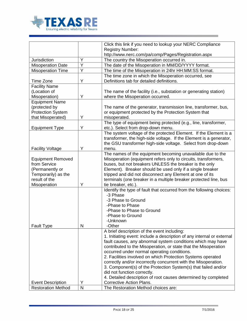
Click this link if you need to lookup your NERC Compliance Registry Number: http://www.nerc.com/pa/comp/Pages/Registration.aspx
Jurisdiction Y The country the Misoperation occurred in.
Misoperation Date Y The date of the Misoperation in MM/DD/YYYY format.
Misoperation Time Y The time of the Misoperation in 24hr HH:MM:SS format.
Time Zone Y The time zone in which the Misoperation occurred, see Definitions tab for detailed definitions.
Facility Name (Location of Misoperation) Y
The name of the facility (i.e., substation or generating station) where the Misoperation occurred.
Equipment Name (protected by Protection System that Misoperated) Y
The name of the generator, transmission line, transformer, bus, or equipment protected by the Protection System that misoperated.
Equipment Type Y The type of equipment being protected (e.g., line, transformer, etc.). Select from drop-down menu.
Facility Voltage Y
The system voltage of the protected Element. If the Element is a transformer, the high-side voltage. If the Element is a generator, the GSU transformer high-side voltage. Select from drop-down menu.
Equipment Removed from Service (Permanently or Temporarily) as the result of the Misoperation Y
The names of the equipment becoming unavailable due to the Misoperation (equipment refers only to circuits, transformers, buses, but not breakers UNLESS the breaker is the only Element). Breaker should be used only if a single breaker tripped and did not disconnect any Element at one of its terminals (one breaker in a multiple breaker protected line, bus tie breaker, etc.).
Fault Type N
Identify the type of fault that occurred from the following choices: -3 Phase -3 Phase to Ground -Phase to Phase -Phase to Phase to Ground -Phase to Ground -Unknown -Other
Event Description Y
A brief description of the event including: 1. Initiating event: include a description of any internal or external fault causes, any abnormal system conditions which may have contributed to the Misoperation, or state that the Misoperation occurred under normal operating conditions. 2. Facilities involved on which Protection Systems operated correctly and/or incorrectly concurrent with the Misoperation. 3. Component(s) of the Protection System(s) that failed and/or did not function correctly. 4. Detailed description of root causes determined by completed Corrective Action Plans.
Restoration Method N The Restoration Method choices are:

PAGE 19 OF 25 7/1/2016
-Automatic, the system went back to normal without human intervention -Manual, operation of manual control switches -Operator, operator action and/or supervisory operation through EMS -Combination, restoration involved a combination of 2 or 3 of the above items
Misoperation Category Y
The category of the Misoperation: • Failure to Trip – During Fault • Failure to Trip – Other Than Fault • Slow Trip – During Fault • Slow Trip – Other Than Fault • Unnecessary Trip – During Fault • Unnecessary Trip – Other Than Fault
Cause(s) of Misoperation Y
The primary cause of the Misoperation: • AC system • As-left personnel error • Communication failures • DC system • Incorrect settings • Logic errors • Design errors • Relay failures/malfunctions • Unknown/unexplainable • Other/Explainable
Incorrect Setting/Logic Errors/Design Errors and Relay Failure/Malfunctions Sub Cause Code N
Select a sub-cause only if: - misoperation involved a microprocessor relay AND 'incorrect settings', 'logic errors', 'design errors' or 'relay failures/malfunctions' was selected for Cause(s) of Misoperation. Valid choices include: -Incorrect Setting/logic/design - Incorrect Numeric Value Specified (this category includes Misoperations due to Incorrect Numerical Value specified of a Microprocessor Relay Setting; this sub cause code does not include field personnel incorrectly inputting the relay settings). Examples would include Misoperation caused by incorrect specification of pickup magnitude, or protection operation time delay, or angle, or positive/negative/zero sequence parameters, etc. Example 2: incorrectly specifying 5 ohms instead of 0.5 ohms. Example 3: incorrectly substituting parameter unit such as msec instead of cycle.) -Incorrect Setting/logic/design - Incorrect User-Programmed Logic Specified (this category includes Misoperations due to Incorrect Logic as specified by the user). Examples would include Misoperation caused by wrong function selection such as selection of positive/negative/zero sequence voltage for polarization, supervision element, loss of potential,

PAGE 20 OF 25 7/1/2016
trip logic , breaker failure logic, 2nd harmonic blocking, etc. Example 2: incorrectly select zero sequence voltage for polarization of directional control for transmission lines sharing common right of way). -Incorrect Setting/logic/design - Incorrect System Coordination (this category includes misoperations due to lack of protection system coordination). Lack of coordination may occur for example when studies are not up-to-date with actual fault values, failure to consider mutual coupling, or does not take in account specific system configuration. It also includes wrong determination of Timed Overcurrent curves and time delays used for coordination purposes. Example 2: Failure to recognize the effect of changes due to transformer impedances and winding configurations.) -Incorrect Setting/logic/design - Incorrect Physical Design (this category includes misoperations due to Incorrect Physical Design). Examples would include drawings errors such as incorrect CT polarity, multiple groundings, wrong wiring diagram, etc. This sub cause code does not include construction personnel incorrectly wiring or failing to follow the construction drawing. -Incorrect Setting/logic/design - Failure to Update Firmware Version by User (this category includes misoperations due wrong application of relay firmware version and misoperations due to latest firmware version not being installed by the user). -Incorrect Setting/logic/design - (Communication) Programming/Logic Error (this category includes protection misoperations due to incorrect programming or application of a microprocessor-based communication equipment; these include multiplexer relay teleprotection devices). -Incorrect Setting - Other (this category includes misoperations that are determined to be associated with Incorrect Setting/Logic/Design of a microprocessor relay, but they do not fit into any of the above categories). -Relay - Power Supply Failure/Malfunction (Failure or malfunction of power supply ) -Relay - AC I/O Module Failure/Malfunction (Failure or malfunction of AC I/O module -Relay - Digital I/O Module Failure/Malfunction (Failure or malfunction of digital I/O module) -Relay - Communication Module Failure/Malfunction (Failure or malfunction of communication module) -Relay - (Communication) Loss of Synchronism (this sub-cause code would capture those protection system failures resulting from systems which depend upon the integrity of the communications network). An example would be a misoperation of a current differential scheme due to loss of synchronism, or loss of time stamping.

PAGE 21 OF 25 7/1/2016
-Relay - Self-Diagnostic Failure/Malfunction (this sub-cause code would capture those protection system failures resulting from an inappropriate action or inaction of the device self-diagnostics). -Relay - CPU Processor Failure/Malfunction (this sub-cause code captures those protection system failures resulting from a failure of the main processor). Examples could be temperature related failures, memory corruption, etc. -Relay - Incorrect Manufacturer Programming ('Bug') (failures as a result of a programming error in the devices firmware, internal programming, or user interface software). These are usually addressed by the manufacturer issuing a new firmware Example: CPU erratic operation caused by interaction with communication software.) -Relay - Incorrect Manufacturer Design (failures resulting from wrong conceptual design in physical hardware, or components, or software). An example of these designs are the various distance schemes that come prepackaged in a line protection. Example 2: sensitive input prone to incorrectly operate for spurious voltage. -Relay - Incorrect Manufacturer Documentation (failures as a result of an action taken which was attributed to incorrect documentation from the manufacturer). Example: incorrect description of relay logic in user manual. -Relay - Unknown (captures relay failure/malfunctions whose underlying sub-cause could not be determined). -Relay - Other (all other failures/malfunctions whose cause has been determined but which has no other "more appropriate" sub-cause code).
Communication Sub Cause of Misoperation N
Communication Interface Failure (Modulator): Power-line carrier radios, fiber optic interfaces, microwave radios, audio-tone/telecommunications, and pilot wire components. Communication Medium: The external signal path, leased phone circuits, cables, transmission lines, etc. Station Signal Path Failure: All signal carrying components within the substation fence including cables, frequency filters, connectors, etc. Incorrect Logic Settings Issued: Channel timing, dip switches, etc. Protective relay settings were considered as a settings problem and not counted as a logic issue (This is difficult to determine when digital relays contain both logic and settings). Human Error (Misapplication in field): Incorrect settings both logic and relay reach, as left conditions, etc. Other: Any Communication Failures which do not fit in the above Sub Causes.
Communication System Type N
If Cause of Misoperation is 'Communication Failure' then this field is used to further describe the type of communication failure.

PAGE 22 OF 25 7/1/2016
Protection System Schemes N
Focuses on keeping the power system stable by isolating only the components that are under fault, thus leaving as much of the network as possible still in operation. Step Distance DCB = Directional Comparison Blocking Scheme (a scheme which allows over reaching elements to trip if a blocking scheme is not received within a predetermined time). POR/POTT = Direct Under Reaching Transfer Trip Schemes (a scheme which uses local under reaching elements to trip locally, and to send direct transfer trip commands to the remote terminal). DCUB = Directional Comparison Blocking Scheme (a type of POR scheme modified for use with power line carrier communications). PUTT/DUTT = Direct Under Reaching Transfer Trip Schemes (a scheme which uses local under reaching elements to trip locally, and to send direct transfer trip commands to the remote terminal). Phase Comparison = compare the phase of the current entering each line terminal to identify internal/external faults. Line Current Differential = measure the phase and magnitude of local fault currents. Differential = used for schemes using local current sources connected to differential relays. DTT = Direct Transfer Tripping Scheme. Breaker Failure = identify a breakers inability to interrupt current within a set time after it has been commanded to trip. Other.
Protection Systems/Components that Misoperated Y
Information on the Protection Systems/Components that Misoperated. If the "Cause of Misoperation" is "Relay failures/malfunctions," "Incorrect settings," "Logic errors," or "Design errors," and the cause is associated with a relay, list relay models (types) and protection schemes.
Relay Technology
Y
If the Cause of Misoperation is “Relay failures/malfunctions,” “Incorrect settings,” “Logic errors,” or “Design errors”, this field is used to identify the relay technology installed. • Electromechanical • Solid State • Microprocessor
Microprocessor Relay Manufacturer N
If the Relay Technology is 'Microprocessor' then select the name of the manufacturer
Is this a Transmission Availability Data System (TADS) reportable event? Y
Whether the Misoperation involved the automatic outage of a TADS-reportable transmission Element (reporting by Transmission Owners only).
Select one or more TADS "Element IDs" for any TADS Y
If a TADS-reportable Element was outaged due to the Misoperation, the Element(s) in a comma-separated list (reporting by Transmission Owners only).
PAGE 23 OF 25 7/1/2016
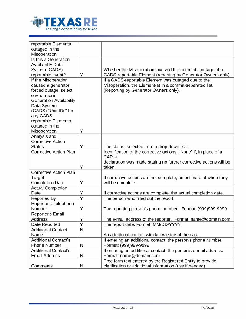
reportable Elements outaged in the Misoperation.
Is this a Generation Availability Data System (GADS) reportable event? Y
Whether the Misoperation involved the automatic outage of a GADS-reportable Element (reporting by Generator Owners only).
If the Misoperation caused a generator forced outage, select one or more Generation Availability Data System (GADS) "Unit IDs" for any GADS reportable Elements outaged in the Misoperation. Y
If a GADS-reportable Element was outaged due to the Misoperation, the Element(s) in a comma-separated list. (Reporting by Generator Owners only).
Analysis and Corrective Action Status Y The status, selected from a drop-down list.
Corrective Action Plan
Y
Identification of the corrective actions. “None” if, in place of a CAP, a declaration was made stating no further corrective actions will be taken.
Corrective Action Plan Target Completion Date Y
If corrective actions are not complete, an estimate of when they will be complete.
Actual Completion Date Y If corrective actions are complete, the actual completion date.
Reported By Y The person who filled out the report.
Reporter’s Telephone Number Y The reporting person's phone number. Format: (999)999-9999
Reporter’s Email Address Y The e-mail address of the reporter. Format: [email protected]
Date Reported Y The report date. Format: MM/DD/YYYY
Additional Contact Name
N An additional contact with knowledge of the data.
Additional Contact’s Phone Number N
If entering an additional contact, the person's phone number. Format: (999)999-9999
Additional Contact’s Email Address N
If entering an additional contact, the person's e-mail address. Format: [email protected]
Comments N Free form text entered by the Registered Entity to provide clarification or additional information (use if needed).

PAGE 24 OF 25 7/1/2016
ATTACHMENT 2 Quarterly Remedial Action Scheme Misoperation Report Form Fields
REMEDIAL ACTION SCHEME MISOPERATION ENTRY FORM
Field Name Required Field
Description
RAS Operation ID Y (This field is automatically populated)
Regional Entity Y The NERC region where the misoperation occurred.
Entity name
NERC Compliance Registry Number Y
The entity’s NERC compliance registry number. Ex: NCR99999 Click this link if you need to lookup your NERC Compliance Registry Number: http://www.nerc.com/pa/comp/Pages/Registration.aspx
RAS Name Y Enter the RAS name as it appears in the regional inventory.
RAS Category Type Y Enter the category type of the RAS.
RAS Operation Date Y Enter the date of the operation in MM/DD/YYYY format.
RAS Operation Time Y Enter the time of the operation in (24hr) HH:MM:SS format.
RAS Operation Time Zone Y Select time zone from drop-down list
RAS Operation Category Y
Select Operation Category from drop-down list. Detailed definitions of the categories are available under the Definitions tab.
RAS Operation Cause Y
Select Operation Cause from drop-down list. Detailed definitions for Operation Causes and additional instructions are included in the Definitions tab.
Event Description Y
Include a description of the RAS operation. Identify all elements removed from service, any generation reduction (MW), or any loadshed that occurred (MW). If the operation was correct, verify that the system conditions were as expected and the mitigation was sufficient. If a misoperation, include a detailed description of root causes determined by completed corrective action plans.
NERC Event Analysis Tracking ID Y
If applicable, please enter the NERC Event Analysis tracking ID for the RAS operation.
TADS Elements Outaged by RAS Operation Y
If applicable, please enter (in a comma separated list with no spaces) the TADS Element identifier for each TADS Element that was outaged as a result of the RAS operation.
GADS Units Outaged by RAS Operation Y
If the operation involved a generator forced outage, please enter the GADS ID of the generator. If there are multiple generators involved, please enter each generator that had a forced outage in a comma separated list with no spaces.
Analysis and Corrective Action Status Y
Select the status from drop-down list. In general, misoperation analysis is conducted first, then a Corrective Action Plan will be developed and implemented to mitigate the misoperation. If a correct operation, select Correct Operation- N/A.
Corrective Action Plan Y Identify the corrective actions. If a correct operation, leave blank.
Target Completion Date Y If analysis or corrective actions are not complete, estimate when either

PAGE 25 OF 25 7/1/2016
will be complete. If a correct operation, leave blank. Enter date in this MM/DD/YYYY format. When copying, use "Paste Values" to retain format.
Actual Completion Date Y
If corrective actions are complete, enter actual completion date in this MM/DD/YYYY format. When copying, use "Paste Values" to retain format. If a correct operation, leave blank.
Reported By Y Enter the name of the person filling out the report.
Phone Y Enter the reporting person's phone number.
E-Mail Y Enter the reporting E-mail address.
Date Reported Y Enter the report date in this MM/DD/YYYY format. When copying, use "Paste Values" to retain format.