PROTECTION OF UNIVERSITY PARK DEPT OF … UNIVERSITY PARK DEPT OF ELECTRICAL ENGINEERING...
170
s4D-Ai34 053 A COMPUTATIONRL PROCEDURE FOR THE PROTECTION OF 112 INDUSTRIAL POWIER SVSTEMS(U) EENNSVLVANIA STATE UNIV UNIVERSITY PARK DEPT OF ELECTRICAL ENGINEERING UNCLASSIFIED C N SALMOND NOV S1 F/G 18/2 N EEEEEEEohEoiE EEEmhhEohmhhhE EhhmhhhEEEEEEI
Transcript of PROTECTION OF UNIVERSITY PARK DEPT OF … UNIVERSITY PARK DEPT OF ELECTRICAL ENGINEERING...
s4D-Ai34 053 A COMPUTATIONRL PROCEDURE FOR THE PROTECTION OF 112INDUSTRIAL POWIER SVSTEMS(U) EENNSVLVANIA STATE UNIVUNIVERSITY PARK DEPT OF ELECTRICAL ENGINEERING
UNCLASSIFIED C N SALMOND NOV S1 F/G 18/2 N
EEEEEEEohEoiEEEEmhhEohmhhhEEhhmhhhEEEEEEI
36
JIL.25 111.4 "6
MICROCOPY RESOLUTION TEST CHARTNATIONA BUREAU OF STANDARDS-1963-A
S ~ . I **.* *.** ''. . . . . . . . . . . . ..%
Approved for publio release!tdistribution unlimited.
The Pennsylvania State University
The Graduate School
Department of Electrical Engineering
A Computational Procedure for the Protection of
Industrial Power Systems
A Thesis in
Electrical Engineering
by
Charles N. Salmond
Submitted in Partial Fulfillmentof the Requirementsfor the Degree of
Master of Science
November 1981 -
I grant The Pennsylvania State University the nonexclusive
right to use this work for the University's own purposes and to make
single copies of the work available to the public on a not-for-profitbasis if copies are not otherwise available.
Charles N. Salmond
83 02 1
" [, . . =¢ , .o , ',, .... . .. .. . ,.. . . .'. . . .

.We approve the thesis of Charles N. Salmond.
Date of Signature:
Fredrick C. Trutt, AssociateProfessor of ElectricalEngineering, Thesis Adviser
0O-23-81 A,__________71__
Dale M. Grimes, Head of theDepartment of ElectricalEngineering
"--oy A gMorley, Profesgor ofMining Engineering, Member ofThesis Coummittee
George A. Etz%*iller, AssociateProfessor of ElectricalEngineering, Member of ThesisCommittee
4@
r .. ' 'T , , g ~~..... ............ . . -.. .. ............... .... ... ...... ,.. *,. *. ..... ,..- * .. " ... ? -. .. .. .. . '.....- ..

ABSTRACT
A procedure is presented that allows an engineer to coordinate
protective devices consisting of fuses, circuit breakers, and over-
current relays based upon load and fault currents. The resulting
digital-computer program makes many of the decisions requiring very
little prior in-depth knowledge of protective devices and power systems
for its utilization.
The coordination procedure consists of six separate programs
that must run in sequence, as the output from one program forms the
input f or the next program. This reduces in size of internal computer
storage required.
The theory is presented with an explanation of each algorithm
followed by a basic flow chart. An example computer run is presented
at the end.

iv
TABLE OF CONTENTS
Page
ABSTRACT. ........ ................... iii
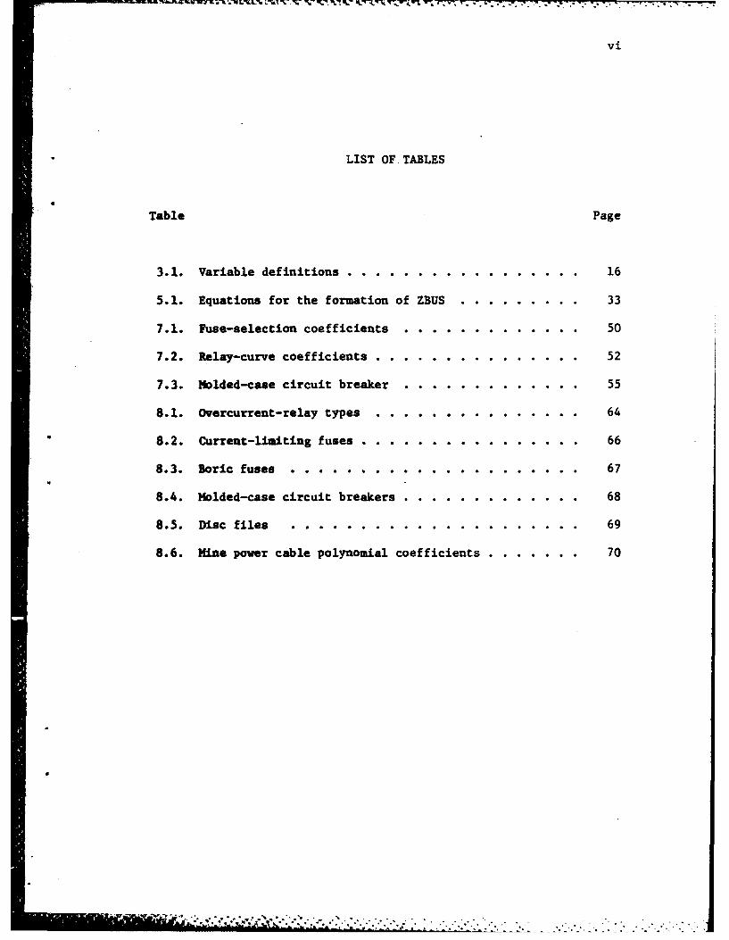
LIST OF TABLES. ........... .............. .
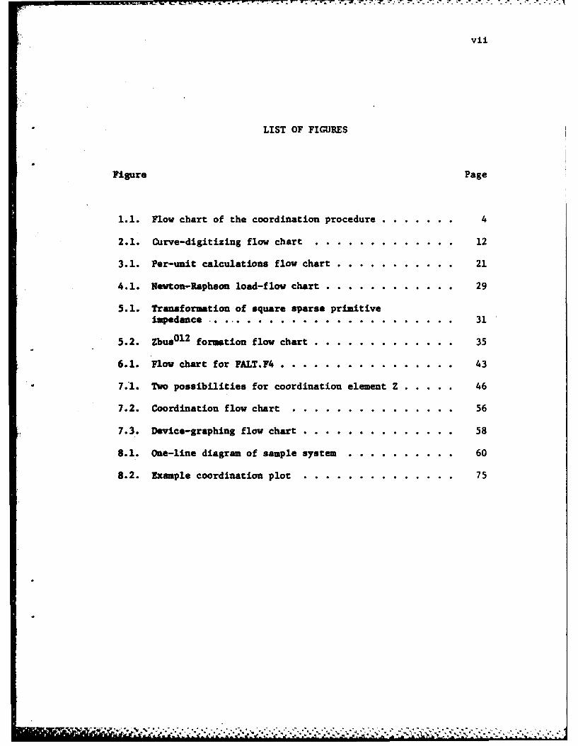
LIST OF FIGURES .. ......... .............. vii
ACKNOWLEDGMENTS. .. ................... .. viii
1. INITRODUCTION. .. ..................... 1Problem Statement .. ................... 2
2. CURVE S100THING AND DIGITIZING. .. .......... 8General........... ................ 8Curve Smoothing .. .................... 8Summary . . . . . . . . . .. .. .. .. .. .. .... 14
3. THE INPUT OF DISTRIBUTIONI-SYSTEM DATA .. ........ 15General ... .. .. .. .. .. .. .. .. .. .. .. 15Per Unit eduction .. .......... ...... 15Formulae for Line Resistance and Reactance. .. ..... 18Suary .. ................... .... 20
4. LOAD-FLOW ANALYSIS.. ......... ... ....... 23General . . .. .. .. .. .. .. .. .. .. .. .. 23Load Flow .. ........ . .. .. .. .. .. .. 23
5. FORMATION OF IMpEDANCE-BUS NETWORK . .. .. .. .. .. 30General ... . . . . .. . . . . .30
Formation oiZ-bus....................30Summary .. ................... .... 38
6. FAULT CALCULATIONS .. ........... ....... 39General . . . .. .. .. .. .. .. .. .. .. .... 39Summary . .. .. .. .. .. .. .. .. .. .. .... 42
7. PROTECTIVE-DEVICE COORDINATION .. ............. 44General .. .................... ... 44Device Coordination. ........... ....... 44Fuse Selection and Coordination. ............. 48Relay Selection and Coordination .. ............ 49Molded-Case Circuit Breaker. .......... ..... 1Summuary .. ................... .... 54

V
Page
8. OPERATING THE PROGRAMS ...... ................ ... 59General . . . . ..... . .. .. .. .. .................... 59One-Line Diagram ...... ................... .... 59Load Flow ............................ 61Solution of Fault Currents ..... .............. ... 61Device Coordination and Plotting ........... 62Sumary ................................. ... 79
9. CONCLUSIONS ....... ..................... ... 80
Recomnendations for Further Work ... ........... ... 81
REFERENCES ................................... ... 83
APPENDIX ACURVE-SMOOTHING PROGRAMS ..... ............... ... 85
APPENDIX BCOORDINATION AND PLOTTING PROGRAMS ............ ... 90
APPENDIX CDISK-FILE FORMAT. ................ ...... 151
APPENDIX DSAMPLE PROGRAM DATA INPUT ... .. ............ 154
' .' .. ,'-v .,'.,.',,--..- ---.-.. -. ..- ,. .-. . .-.
Vi
LIST OF.TABLES
Table Page
3.1. Variable definitions .. ............. .... 16
5.1. Equations for the formation of ZBUS .... ....... 33
7.1. Fuse-selection coefficients. ............... 50
7.2. Relay-curve coefficients .. ............ ... 52
7.3. Molded-case circuit breaker. ............... 55
8.1. Overcurrent-relay types. ............. ... 64
*8.2. Current-limiting fuses .. ............ .... 66
8.3. Boric fuses. .............. ........ 67
8.4. Molded-case circuit breakers .. .............. 68
8.5. Disc files .............. .......... 69
8.6. Mine power cable polynomial coefficients. ... ..... 70
vii
LIST OF FIGURES
Figure Page
1.1. Flow chart of the coordination procedure ... ....... 4
2.1. Curve-digitizing flow chart .... ............. ... 12
3.1. Per-unit calculations flow chart .. ........... ... 21
4.1. Uewton-Raphson load-flow chart .... ............ ... 29
5.1. Transformation of square sparse primitiveImpedance .. ..................... . 31
5.2. Zbus 0 1 2 formation flow chart ............. 35
6.1. Flow chart for FALT.F4 . ............... . 43
7.1. Two possibilities for coordination element Z ....... 46
7.2. Coordination flow chart .... ............... ... 56
7.3. Device-graphing flow chart ..... ........... 58
8.1. One-line diagram of sample system .......... 60
8.2. Example coordination plot ........... ..... 75
-*r 2 .- *i*
viii
ACKNOWLEDGMENTS
The author is indebted to Dr. Fredrick Trutt and Dr. Lloyd
A. Morley for their support and guidance throughout this thesis
project.
Dr. William S. Adams and his staff of technicians in the
Electrical Engineering Hybrid Computer Laboratory, Mr. John Griebling,
.and Hr. Robert Hirlinger were especially helpful.
The author appreciated the comments and suggestions of Dr.
George A. Etzweiler in his critical review of this work.
- AL
1. INTRODUCTION
A prime objective of electrical engineers working on the design,
operation, or maintenance of electrical power systems is to provide
reliable, efficient power to their customers. The distribution system
has always been a weak link in the power chain. often, the catas-
trophic results of a fault are easily seen, but the cause may be
extremely difficult to find. A distribution system, either in the
utility or the user's facilities that is not adequately protected from
electrical faults is both dangerous and costly. An unsatisfactorily
protected system can cause considerable inconvenience and damage to
equipment. Adequate protection is not a set definition. Each load
system is different with its own set of boundary values.
In a distribution systemthe flexibility of design reduces
near the generator or the load. Usually the generator or load protec-
tion is designed as an integral part of the equipment by the manufacturer
and any changes should only be undertaken with their counsel. Moving
away from the generator or load, the priority shifts from load pro-
tection to distribution protection. It must never be forgotten that
the load, distribution, and generation systems must be protected in
such. way thata device that operates satisfactorily in one system
cannot have a detrimental effect on another system. In this thesis
the distribution section is attached from an infinite-bus power
source to the load-protection device. The programs provide the
- t .A -V .. . . . . . . . . .

2
proper setting of a chosen device in order to provide good protec-
--. tive coordination. Proper coordination is achieved when a device
closest to the fault clears the fault or overload condition before
the rest of the system is disturbed. In order to achieve this end by
manual means, extensive mathematical calculations and experience are
required. As a direct result.proper coordination is often not achieved.
The use of digital computers to solve the coordination problem makes
amore exacting solution. However, computers with large internal
memory are required to solve these problems. Several approaches
to computer solutions have been published [1-4].
Problem Statement
The purpose of this thesis is to develop the procedure and an
interactiv computer program for a generalized case of device coordina-
tion. This coordination should include fuses, relays, and molded case
circuit breakers. The phases of research are as follows.
1. Develop a computer procedure to compute the one-line program
per unit values.
2. Develop a computer procedure to perform a load-flow analysis.
3. Develop a computer procedure to compute line-to-line ground
and three-phase faults.
4. Develop and apply p. -u) .for mathematical representation
of line X/R data, fuse, molded-case circuit breaker, and
relay-curve time-current characteristics.

3
5. Develop a computer procedure to coordinate the devices
from phase 4 with the data derived from phases 2 and 3.
Although the coordination programs are written for the PDPlO
computer, it requires no more than 25K bytes of internal memory and
a disk unit to solve any system of 30 buses and 100 elements. Almost
any large system can be reduced to its smaller parts composed of 30
buses or less. As each segment is coordinated, it can be represented
by a load and its protective device. In this manner a 300-bus system
could be divided into smaller segments and in 11 runs would be com-
pletely coordinated. The step-by-step approach used here allows for
insertion or extraction of data before proceeding to the next step.
Figure 1.1 is a basic flow chart of the coordination program. Here-
after- it will be referred to by its individual parts.
When the coordination process has been completed, a load flow
study and a fault analysis has been performed as well. The major
assumptions that have been made are listed here. Other minor ones
are Included in the corresponding chapters. These assumptions have
been made in an effort to keep the solution as general as possible.
1. The incoming line is assumed to be an infinite bus.
2. Assymetrical currents are neglected. Devices are coordi-
nated on the basis of symmetrical fault currents.
3. Only synchronous-motor contributions to the fault
currents are recognized. If a large induction motor

4
StartINPUT.F4
Inputline data
No Selectnew wire
Finished No *type
Yes
Inputload data
Convert toper-unitvalues
StartLODFLO.F4
FO-012
ZBUS
Performload-flow Startanalysis
FALT.F4
Input mutuacouDl tmutouDline.et
Figure 1.1. Flow chart of the coordination procedure.

5
AB
Solve for30, line toground faults
StartCOORD. F4
Input loaddevices
nputbcpload
Coordinatebackup withprimary
Inputdevice
Coordinate
jFinished No
Yes>
C
Figure 1.1. Continued.

6
C
StartPLOTD.F4
Figure .1. Coiipued
rplot
7
is present, it may be added as a fictitious synchronous
motor.
4. Line-charging shunt admittance is ignored.
5. Prefault current and voltages are neglected in fault-
current computations.
6. Different sizes of fuses have the same time-current curve
shape.
7. Overload conditions are 125% of full load.
8. The system has a balanced three-phase load.
In this thesis each phase of research in the problem statement
has a chapter devoted to it. After describing the computational
methods used in curve smoothing, the coordination problem begins with
data input. Next the fault currents are solved followed by the
actual coordination program and device response graphing. Finally,
a sample distribution system coordination problem is described.

2. CURVE SMOOTHING AND DIGITIZING
General
In this chapter, the methods for using a data digitizing "numonics"
device and the curve smoothing program of Appendix A are explained.
The various device equations that were found that adequately represented
the particular device's time current curve are also described.
A method was described in Wagner [1] for performing this by
using the PDPl0 computer. This least-square curve-fitting program [1]
was expanded to eliminate any external subroutines that may not be
available. The coordination program makes extensive use of polynomial
functions whose coefficients were derived by using the least-sqiares
curve-smoothing technique.
Curve Smoothing
Electrical Cables. Coefficients for the mathematical modeling
of resistance and reactance were taken from data for mine power
cable (5]. This is used as only one type of cable or wire. Any other
type may be modeled by the same procedure. For instance, either actual
cable or line data could be used directly [6],or the theoretical resis-
tance and reactance for each size could be calculated f5-8].
n n u .... lil~lI ' i " d" h"a" in h"- - : "'< '"'-......................"..-..-..--......-..... .

9
Fuses. Two types of fuses are used in the coordination pro-
gram. These are current-limiting and solid-material boric-acid power
fuses. In each case, the curve shape is assumed to be the same for
different sizes. The low-current asymptotic value is called the
"ofset." Each fuse has a minimum and a typical operating time. In
fuse coordination,both values must be used in describing the operating
envelope of a particular fuse. The higher typical operating time
curve is referred to as "Of set 1." By this means, any fuse can be
completely described by four equations, where:
nLog Tmin - ( E a (Log Current -Ofset)J - 2 (2.1)
min Jo
nLog T "( E ak(LOg Current-Ofsetl) k 2 (2.2)
.- k-0
Fuses are selected also by using mathematical models. To
select a fuse, the program uses the overload-current value as the
variable in the polynomial function. The result is the device number.
In curve smoothing, variables can assume no value less or greater than
those originally used as data for the curve-smoothing program, or large
errors can result.
Molded-Case Circuit Breakers. Like the fuses discussed above,
each molded-case circuit breaker consists of an operating envelope
bounded by a minimum value and a maximum value. Unlike fuses, however,

10
a table look-up approach is used in selection of a device and its
setting because of the smaller number of sizes and magnetic-trip settings.
Relays. Wagner [1] discusses the representation of the family
of relay curves for each type with one polynomial equation comprised
of four coefficients. The 0t h power coefficient was left out as a
variable for coordination. Unfortunately, this method proves unsatis-
factory when working with more than one relay type. It was found that
each relay could be represented by five coefficients. The 0 th power
coefficient is necessary in that it provides the time displacement
necessary for minimum time dial setting. The curves were derived
using the procedure below.
Westinghouse Company type relays were used. An average curve
was taken as time-dial 4.; This curve was reduced to a polynomial
function. The time difference between time-dial 4 and time-dial 1/2
taken at 20 times the pickup value is subtracted from the 0th coef-
ficient. Twenty times pickup was a good value for computing the time
difference as the time value changes very little for increases in
current beyond that point. The resultant curve was the average shape
of a time-dial setting of 4 now shifted to minimum setting. This allows
for time values computed during coordination to be sunned with the 0th
coefficient. The curves are then represented as follows:
n4
Log Time = ( a (log(Current Value)j ) +
Log (Time Setting)

11
This allows the use of more than one type of relay in each
coordination as it separates time setting value from relay type.
Curve Digitizing. The device's time versus current curves
were digitized by using a NUMONICS electronic graphics calculator
(EGC). The NMONICS EGC is designed to translate graphic information
on any medium into digital information. Complete information on its
usage may be found in -NUMONICS Electronic Graphics Calculator [9].
The NUMONICS EGC then provided a convenient way to enter X-Y coordinate
data representing any curve onto disk. Since this device works in
length in inches, the data has to be normalized to its proper units.
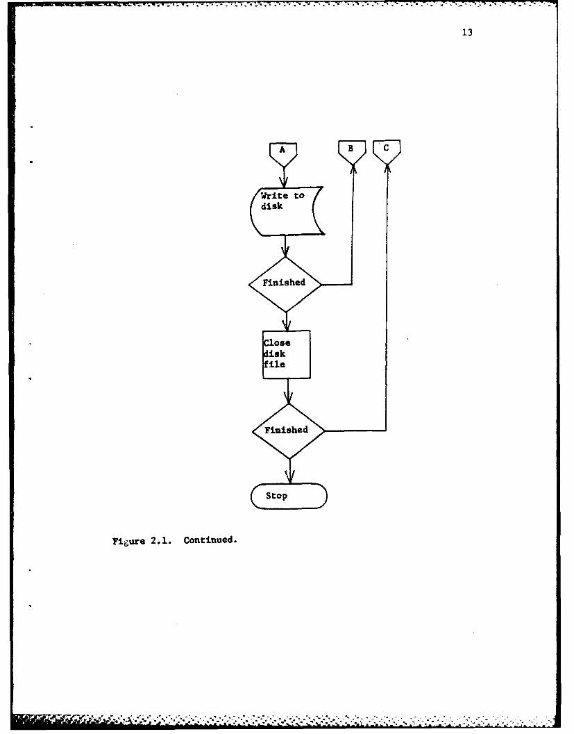
A simple program DIGIT.F4 was written to norii'lize and store
onto disk the NUMONICS EGC information. The program flow chart is
shown in Figure 2.1.
Curve Smoothine. The curve-smoothing program contained in
Wagner [1] was used as a basis for the curve smoothing program DEV.F4.
Unnecessary parts were removed and a double precision matrix inver-
sion routine was added. This prevented the necessity of using
subroutines contained in the computer's SSP routine files. The
inversion routine was converted from The Pennsylvania State University
Computer Center's matrix inversion routine CMINV which inverts a
complex square matrix. This routine in turn was converted from the
SSP routine MINV [10].
Since it has its own inversion routine, this curve smoothing
program can be easily expanded to any number of points and any
dimension of fit by changing the dimension statements. The flow
chart and procedure remains the same as in [1]. A complete program
listing may be found in Appendix A.
*' e .-. . 9" ",. . . ... "°
. .
+' . . .+'. -. ,,..-.............-.... ... ..... ,...,.. .. .. ....

12
F1.pie 2.. Curedi t artl lo ha
F 4 ** ~ . * .. * . . . .- . . . .
F~~~ a
.
13
A B C
Write todisk
Finished
Cosedisk
Figure 2.1. Continued.
14
Summary
Polynomial functions describe the various device-response
curves, line X/R data, and fuse-selection criteria. The coefficients
for these polynomial functions are found from data entered using a
digital-data device or manual input. This data is reduced by a curve-
smoothing program to the desired function.
The start of the coordination problem begins in the next chapter
with line and load data entry.

15
3. THE INPUT OF DISTRIBUTION-SYSTEM DATA
General
Usually the first step in performing any calculations on a
distribution system is to reduce all system values to per unit. The
methods used to do this in the program will be described in this
chapter. Errors can be introduced easily when converting to the per
unit system using manual calculations. Program INPUT.F4 was written
to perform this function as well as computing line resistance and
reactance values and storing all system data on disk for use in sub-
sequent programs.
Per-Unit Reduction
The program uses the following formulas to convert to the per-
unit system (8]. (See Table 3.1 for variable definitions used in this
thesis.)
zBase " (KVBase)2/MVAase
Z p.u. M Z()/ZBase
IBase KVABase /KVBase
V V ~e,

16
Table 3.1. Variable definitions.
ZGZ) element impedance
zP.U. impedance in per unit
Xd subtransient reactance
P. real power bus p
Qreactive power bus p
EP complex voltage bus p
I complex current bus pP
Ypq Y bus element bus p to q
Ypq,rs admittance value from primitive admittance matrix
Z Z bus element bus p to qPq
3pqqpq impedance value from primitive impedance matrix
Zf fault impedance
Yf fault admittance
.................................. ..... ........

17
z.KV Base given) KVABase new)KVBase new KVABase given
Utilizing the above formulas it is possible then to represent all
elements in the distribution system on a per-unit basis. Loads need
to be included also in the one-line representation.
The program allows loads to be represented either by induction
motor horsepower, synchronous motor horsepower, kVA, or current.
Loads are entered in the following format: Bus number/horse-
power, kVA, current/power factor. The program assumes 100% efficiency
so one must use:
HPEntered - HP/Efficiency (3.1)
If information on efficiency and power factors are unknown, the follow-
ing equations may be used instead of 3.1 (9].
For induction motors, use:
HPEntered - HP x 1.1627
Power Factor - .86 (3.2)
For synchronous motors use:
Unity Power Factor HP 1.139 x Horsepower (3.5)
.8 Power Factor HP - 1.18 x Horsepower (3.6)

uaa4~~Egt~~w.~'zz~~..2~~..... *.1 ail -. 1 -. 1 *2 - ' ~ ~ * ~ . . .3
18
Formulae for Line Resistance and Reactance
Element data is entered in the following format: line bus/
load bus/cable length in feet/wire size/transformer P.U. impedance/
size in M A/line voltage in KV/load voltage in KV.
Wire sizes that are entered in American wire gauge (AWG) are
converted to MCM wire gauge by using the following formula [1]:
2
MCM - [(.005)[(1.229)(36 AWG)] x 1000 (3.7)
Once the wire size is in I-IM, the line resistance and reactance are
computed using the polynomial coefficients that were found by the
procedure in Chapter 2.
nResistance or reactance = E a [log(MCM)IJ (3.8)
j-0 J
The program should not be limited to just one wire type. The program
does this by reading wire coefficients aj above from disk so that each
time the program is run it can compute element data using different wire
types until the entire system has been completely entered.
Transformers become very important in that they can become the
highest source of resistance and reactance. By their connections and
neutral impedance, they determine the magnitude of zero--sequence current
that will flow in the particular element. The program allows for this
input and writes this information in the particular disk files for use
later on in fault analysis.
' ~ ~ .. .. ' . ' . . - .- -" .- . • . . • .- , .s - ,.
19
Transformer inrush and withstand values must also be calcu-
lated. These values must be used in coordinating protective devices.
These devices must pass inrush currents but open under conditions of
exceeded transformer withstand currents. The algorithm in the program
is based on average values. If test data is available this should be
entered directly by changing the transformer data disk file directly
after the program is run and before proceeding with coordinations.
Inrush and withstand values are computed as follows [111:
Inrush -12x(Transformer Base Current) (3.9)
Withstand @2 Sec 2 5x (Transformer Base Current) (3.10)
withstand @5 Sec -1 4 .5x (Transformer Base Current) (3.11)
Transformer withstand is some value between the two second value to the
five second value and depends upon the transformer impedance. It is
fairly easy, however, to have the device protect the complete range
of withstand values and the program is written to accomplish this task.
Synchronous subtransient reactance is computed as follows [11]:
(Per unit KVA) x (.17) jX id (3.12)
20
One of the problems encountered in computing transmission line
impedance is a reasonable calculation of the zero-sequence impedance.
The computer program assumes that this value is two times
the positive-sequence impedance [8] if nothing is entered when the
computer asks for the zero-sequence impedance multiple. If a different
value is entered5 the computer multiplies the positive sequence reactive
value by this multiple to arrive at the zero-sequence value.
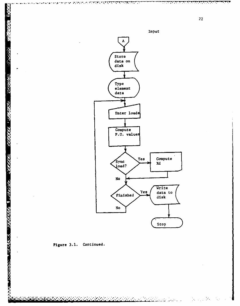
A basic flow chart follows in Figure 3.1 with a complete program
listing in Appendix B.
Summary
The first step toward solving the coordination problem is com-
pleted. All element data has been converted to the per-unit
representation. The next logical step is to perform a load-flow
analysis to determine the full load currents in each element.

21
Flow Chart Input
Str
Figue 31. er-nitcalclatonsflo chRt.d
Redelmn
ad.............................
22
Input
Storedata ondisk
S Typeelementdata
Enter loads
Compute
P.U. values
Fgr Computeoad ?
No / --
/ ~Write (Finished Ys data to
disk
Figure 3.1. Continued.
23
4. LOAD-FLOW ANALYSIS
General
In order to establish overload conditions on each element,
the load currents must be determined. This is done by using a load
flow analysis. The Newton-Raphson Method using Y-bus [12] was chosen
because it required the least amount of iterations to obtain a solu-
tion to the load-flow problem.
Load Flow
In this method Y-bus must first be formed from the primitive-
impedance network. When mutual coupling is ignored, Y-bus can be
formed easily by algorithm. Any system can be completely represented
by a set of equations [8,12].
Ibu s (Y bus)(E bu) (4.1)
Ebus and Ibus are column matrices with one entry for eaLh bus
in the system. Ybus is a square matrix of order equal to the ,aumber
of buses in the system. Therefore, once all bus voltages are :nown and
Y-bus is formed, matrix multiplication gives the desired load currents.
.............................................
in'r*° . ° ... o .. . ° . . , . = *... ° - ° - ° . • °
24
However, there is no direct approach to obtain the bus voltages.
The only approach to use is that of iteration. The Newton-Raphson
method accelerates the iteration process so that normally an accurate
answer is obtained after three iterations.
The power at bus p is (from 4.1):
*.IPp-jQp = Ep p
pQ p pp
P p-JQp E Z Y E (4.2)qq
Ep ep+JfpYpq Gpq-JB pq (4.3)
so
nP p E {e (eq G +f B )+(f G -eB pq) (4.4)PP q1 P q Pq q pq qp Pqp
.q=1
nQp ! (fp(e q pq+f B )-e (fq G }-e B ) (4.5)
q-1 ~'q q qpq p pqqpq)
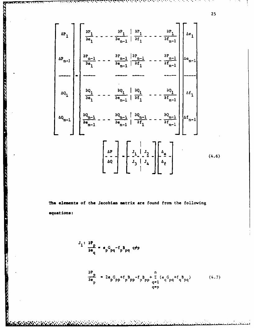
The Newton-Raphson method uses the Jacobian matrix of partial-
differential equations as follows:
A id;". ..m m ° J - " ' " " ' "+'W '" '' .' ; : "I " • ' -.
25
Ap P_1 ap 1 aP 1P1 Ae 1
e nI af a fnI
APn Pn_-1 n-1 la Pn-l aPn-I Aen_1ae ae -, lf - f - leI n1 -i 1f fn-i
m-- -
AQ1 aQ~ 1c~ 3Q Q, aQ Af1
AP 1 Q1 2 Ae
- - - - - - - (4.6)AQ 3 4 A f
The elements of the Jacobian matrix are found from the following
equat ions:
: 1 p = - e G -f B q~p30aq p pq p pq
aeP- 2e G +f B -f B + Z (eq +f q B pq) (4.7)p ppp ppp ppp qpq
qop
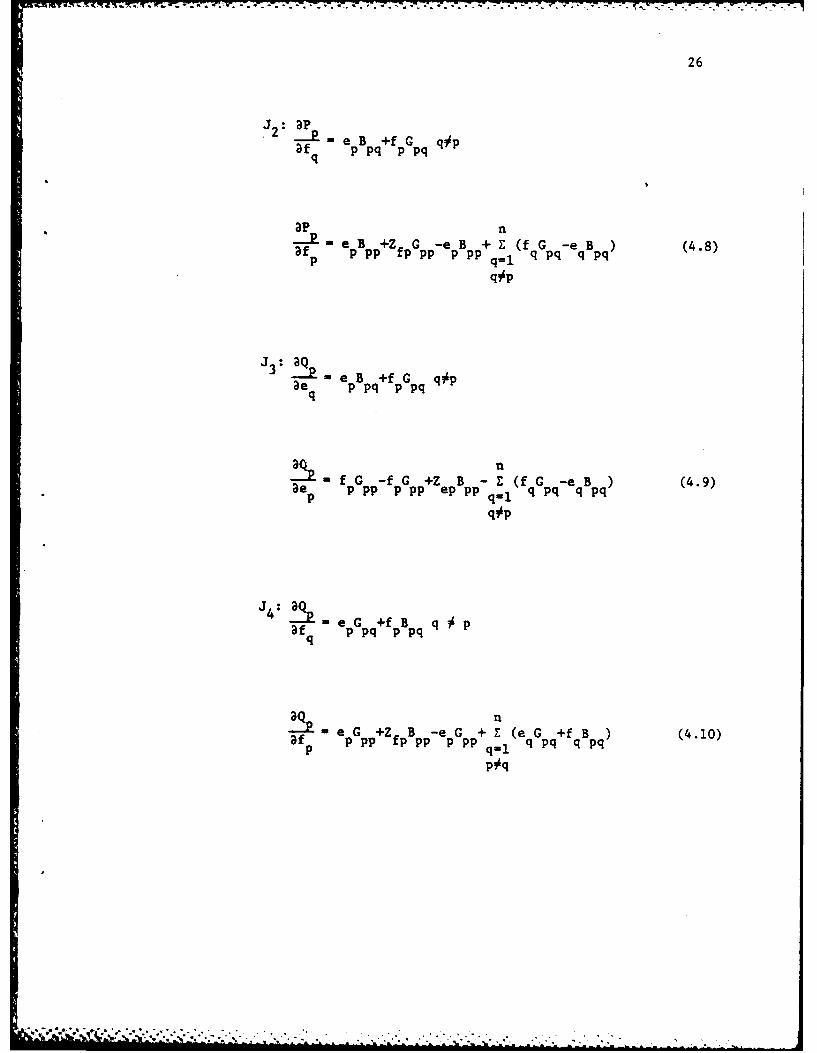
26
. 12 p -e B +f G q~pfq p pq p pq
apn
af- e pB pp+Z fpG p-e pB pp+ Z (f qG p-e qB p) (4.8)p q
q~p
J 3 aQ - eB +f G q~pae q p pq p pq
qn
-e f pG pp-f pG pp+Z epB pp Z (f G -e B )(4.9)pp ppePq., 1 q pq q pq
q~p
fq p pq p pq
'- e G +Z B -e G + Z (e G +f B )(4.10)af p ppp fpp PP P P q pq q pqp pq
27
Bus #1 or the swing-bus voltage is known. The swing bus is
the bus that will provide whatever power the system requires. The
program begins by forming Y-bus by using the primitive-impedance matrix
generated by INPUT.F4 of Chapter 3. Since mutual coupling is ignored,
the y-admittance matrix can be found by inverting each member of the
z-impedance matrix found in disk file TEST.DAT. Ybus matrix is formed
using the algorithm below.
Diagonal elements are formed as the sum of all admittances
connected to that bus or node. Off-diagonal elements are the negative
of the admittance connected between the buses or nodes.
If more than 10 iterations are performed, the program stops and
informs the user that either an error has been made in design or data
entry. Upon successful completion of the program, a load-flow analysis
may be obtained by printing file DISK.DAT. The program puts the load
currents in the proper format and file for later use in the coordination
program. A flow chart follows in Figure 4.1, and a complete listing
is given in Appendix B.
Summary
This load-flow analysis obtained can be very useful in analyzing
the distribution-system design. It can be used to point out locations
for power factor correction as well as potential problems due to under-
sized wiring.
The load currents found here are stored on disk to be used in
the coordination program. The next step before beginning the
.. ;.. .......... .

28
coordination program is to solve for all fault currents. Z-bus must
be formed to compute these currents. The methods used to do this
follows in the next chapter.

1~~ 'ZZ.TW- -_ -..r .4 ' - . -- . - . .q ..9 -- I - 1 ~ .6S7
29
Start
Readdata
Formbusadmittance
matrix ThustAssume busvoltages
real and
No reactivebus powers
Fiur 4.1 >etnRao lodfowca0
-~mpv. ~ ~. .. ... ....Yes
S.---Ye Calculate~
*Coveg Ye line.-..

30
5. FORMATION OF IMPEDANCE-BUS NETWORK
General
The formation of the impedance bus network (Z-Bus 0 1 2) by
algorithm is the first step toward solving for fault currents. In
this chapter this algorithm will be discussed as well as other problems
encountered in matrix compression.
Formation of Z-Bus
Once the one line diagram has been completed, the primitive
impedance matrix that was found in INPUT.F4 is a partially filled
matrix. However, it is not in the proper format for the formation of
Z-bus as it contains no coupling. The primitive impedance matrix must
change from one of order equal to the number of buses to one of order
equal to the number of elements. This matrix becomes a very large
sparse matrix. The memory required to store this matrix becomes too
large to fit in a small computer. A method was derived to only store
the non zero values and their location in the matrix. Since the matrix
is triangular only the top half is stored (Figure 5.1).
Diagonal elements found in INPUT.F4 are stored in "ZD." ZD
is a three-dimensional matrix, ZD(200,2) where (X,I) is the element
number and (X,2) is the diagonal value.
*I .N ~-:- . -5

31
ZD(200,I)
xD (200,1
Elements X,Y,Z
(A) 3
- ZM (200,2)
Number locations matrix (A) -(# elements) 2X 2Number of locations of alternate method - 8 X (#/ elements)
Figure 5.1. Transformation of square sparse primitive impedance.

32
The off diagonal mutual coupling Zm is a three dimensional
matrix also where (X,l) is the location value A+jB. Element A is
coupled to element B. Location (X,2) is the coupling value. Fortun-
ately, partitioning makes it necessary to assemble a square matrix for
inversion of only the coupled elements. Since coupling only exists in
zero sequence, this applies only to the zero-sequence Z-bus matrix.
In the formation of the Z-bus matrix, bus 1 is the reference
bus for all calculations. Z-bus is formed by starting with element
one and proceeding with each element in turn. An element is either a
link or branch. A link means that both buses have been used earlier;
a branch means they have not been used earlier.
Like Y-bus in Chapter 4 any system can be represented by
Ebus012 . Zbus012 Ibus012
Formation of Zbus 012 can be formed either by the incidence,
network-matrices method [12] or by algorithm. Formation by algorithm
is much simpler and is used here.
After forming the primitive impedance network, it is a straight-
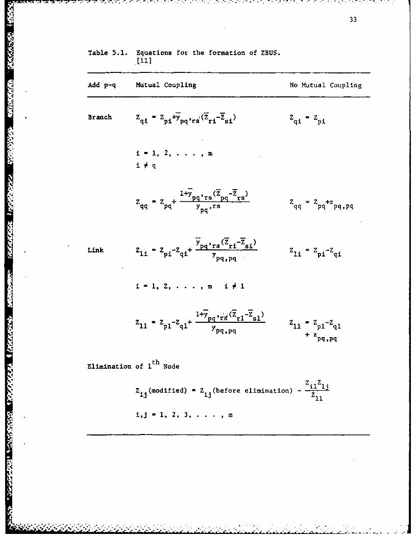
forward application of the equations of Table 5.1.
:4
* C-o:. . -.- . .
33
Table 5.1. Equations for the formation of ZBUS.
Add p-q Mutual Coupling No Mutual Coupling
Brnc +3 ( z qi p
Brnc Zq pi ypqtrsi ri si) q Z =z
i1nl2,. .
i7 q
Z - Z + 1ypq'rs (zpg : rs) Z Z +zqq pq yq ,rs qq pq pq~pq
y Pr (Z -Z )
L n i , pi -Zqi + P2 Ypq pq zli z i -qi
i -l, Z,. . . 1m i
-1,z p-Z q + 1+y pg'r4(Zrl:z sl) z 11,z p-Z qp1 qi Ypqgpq 11 p1z
pqppq
Elimination of 1 th Node
Z (modified) =Z (before elimination) - il z jii ij Zil
i,jn1, 2, 3, m
-1 7.
34
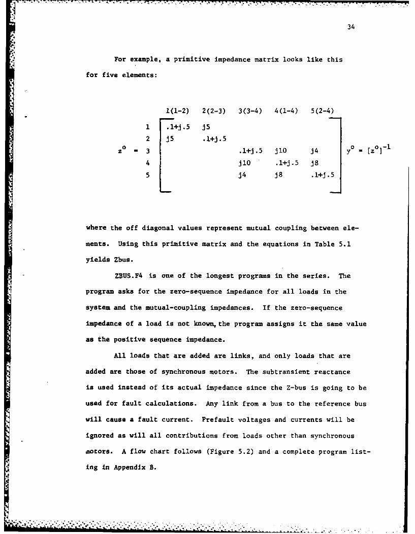
* For example, a primitive impedance matrix looks like this
for five elements:
1(1-2) 2(2-3) 3(3-4) 4(1-4) 5(2-4)
1 .l+j.5 JS
2 j5 .l+J.5
z 3 .l+j.5 jlO j4 y = [z 0
4 jl0 .l+j.5 J85 j4 j8 .l+j.5
where the off diagonal values represent mutual coupling between ele-
ments. Using this primitive matrix and the equations in Table 5.1
yields Zbus.
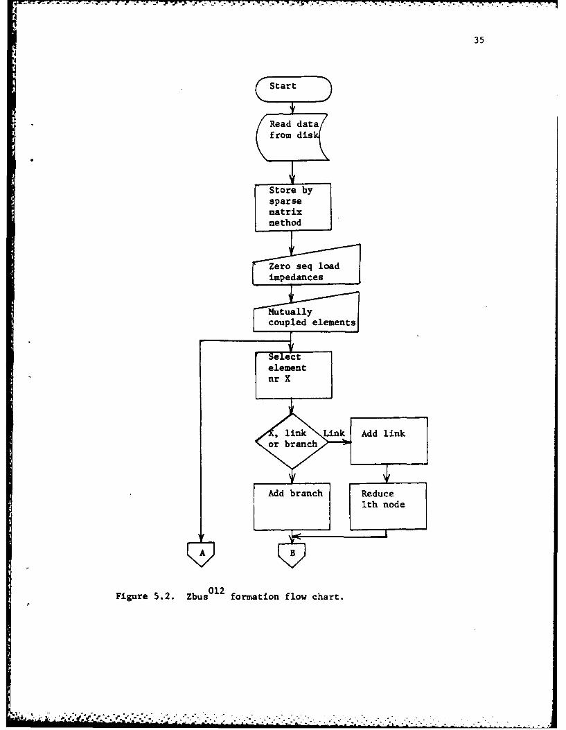
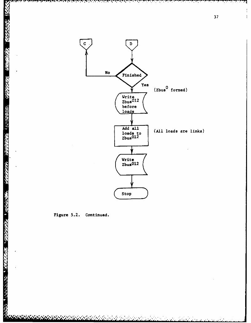
ZBUS.F4 is one of the longest programs in the series. The
program asks for the zero-sequence impedance for all loads in the
system and the mutual-coupling impedances. If the zero-sequence
impedance of a load is not known, the program assigns it the same value
as the positive sequence impedance.
All loads that are added are links, and only loads that are
added are those of synchronous motors. The subtransient reactance
is used instead of its actual impedance since the Z-bus is going to be
used for fault calculations. Any link from a bus to the reference bus
will cause a fault current. Prefault voltages and currents will be
ignored as will all contributions from loads other than synchronous
motors. A flow chart follows (Figure 5.2) and a complete program list-
ing in Appendix B.
i i .. . .. . , _1 . _ ' ' . ,
7- 7-.~...
35
Start
Read datafrom dis
Store bysparsematrixmethod
Zero seq loadimpedances
012tullFigue 5.. Zb fomatouflow charet
.. . .. . . . . . . . . . .. . . . . . . . . . . . . .. . . . . . . .

-S.~~ ~ ~~~~~ -W T - . .. .A - . *
36
A B
No
Ad S irsnc redc
Figure .2. Cotinued
r- ~ -number
37
C. D
{Zs buso formed)
Add all {All loads are linkslloas t
Figure 5.2. Continued.
38
Summuary
Zbus 012 is formed by algorithm allowing for mutual coupling
between elements. The next step in the coordination procedure is to
solve for fault currents. This procedure follows in the next chapter.

39
6. FAULT CALCULATIONS
General
The final program required before executing the coordination
program is FALT.F4. This program computes all the possible line-to-
ground and three-phase-fault currents and prepares all other load
data for entry into the coordination program. The procedure to
accomplish this will be discussed in this chapter.
Fault Currents. The equations describing the fault currents
need to be derived [12].
Three-Phase Fault. For a fault at bus P:
I p(F) 012 0 YF02(U+Z pp012YF 012 )-l EP (O)012 (6.1)
where U is unity matrix, Ep (0) is prefault voltage, and YF is the
fault admittance matrix for a three-phase fault.
SF 012 y YF 0 1 0 (6.2)
0 0 1
""L

40
Substituting (6.2) into (6.1)
0 0 0 1+Z 0 0
I P() YF 0 1 0 pp +Z ppYf 2/3
00 1 1+Z Pf 0
0 00 101+Zo0
012 1 pp 1P(F)=YF 0 1 0 1+Z pp 1 12 3
1Zpp2
0 0 0 0
01 1 0 63I (F yF 4Zpp 1YF 1 01(63
0 0 120
J LF
Since Zpp' 1 Zpp 2 and zf m 1/ lf
1 3 10=0 1 2=0 (6.4)PF F+p PP
41
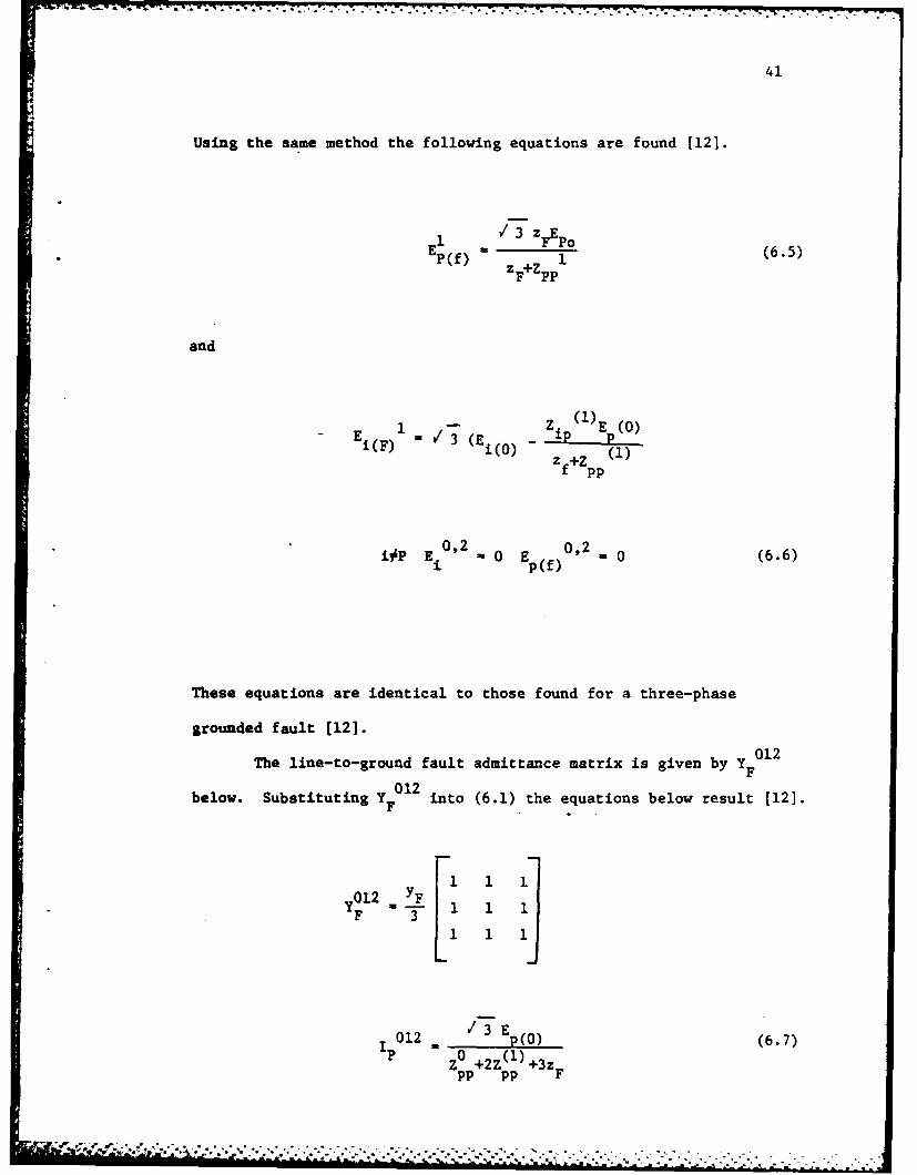
Using the same method the following equations are found [121.
1 F EPo (6.5)P(f) FezPPI
and
E I 3 Z i E p(0)i()1(0) Z f+Z pp(1)
iOP E -O02 E -~)02.0 (6.6)
These equations are identical to those found for a three-phase
grounded fault [12].
The line-to-ground fault admittance matrix is given by Y F012
below. Substituting Y F01 into (6.1) the equations below result [12].
,~l2 YF 1 1 13
1 012 - 3 E 0(6.7)P Z0 +2Z ()+3z
pp pp F

424
-Z (0)
E012 V E p0 Z (0)+Z (1)+3z (6.8)z 0)+2Z (1)+3zF pp pp F
pp
- (0)10 3 EZ iP
012 . po E 3 -( z (1) (6.9)i(F) E(o) Z (0)+2Zpp (1)+3zF ip
i~p09 p p. IF _ Z ip()
The value of zF is entered from the keyboard when asked by the program.
All of the equations are available now to solve for all fault currents.
All post-fault bus voltages are solved. Using these bus voltages
each element fault current is determined. These currents are stored
onto disk so that they may be used in both the coordination and graph-
ing programs.
Summary
The programs thus far have solved for all load and fault cur-
rents but no coordination has been discussed. Now the coordination
problem is ready to be addressed. In the chapter that follows, the
protective devices for the distribution system will be coordinated.
d' wa

43
Start
Read Zbus
Set all busvoltages
Accept faultimpedancevalue
Write busvoltagesto disk
Find allelementcurrents
Convertsymmetricalcomp to three
unit to real faults
Figure 6.1. Flow chart for FALT.F4.
* - *.' .*_ . * * ,* , .... . -. . . ., , ,, . . - . -' " ,"_.. . . . - _i , i--. '- .
H i I I I - I I I i " nI 0 * - - - t 1 '-

44
7. PROTECTIVE-DEVICE COORDINATION
General
In this chapter, the protective-device-coordination problem
will be discussed. A computational method is put forward that allows
a digital computer to solve the problem.
Device Coordination
One of the best methods to approach coordination is a step by
step device selection and setting working from the load toward the
source. A load is the best place to start because there is not much
flexibility for device setting at a load. The load flow analysis of
Chapter 4 provides the overload values for the various loads. This
enables a definite overload setting for each device protecting a load.
Since overload currents are a primary concern at these buses, all fault
settings can be placed at six times the full load currents. This should
allow for normal starting currents. Care must be taken so that an
instantaneous tripping element will not open under normal starting
conditions. From the loads it is a straightforward process to place
a line side device curve next to its load side curve to insure that
proper coordination is achieved. By taking this approach, each device
depends only on one other device.

45
This program is written with the option of entering two devices
in each element--one located at each bus. From this approach,
obviously two possibilities can occur. Either the device is on the
line side of the element or on the load side of the element (Figure 7.1).
If it is the line-side device, its setting depends only on the one
load-side device. It must be coordinated for the fault current at
* the load bus and not the line bus [1]. Devices must be coordinated
for a minimum possible fault current which will be discussed later.
If the device is on the load side and it does not protect a
load, then it must protect a following bus. This device must then be
coordinated with all line-side devices connected to the bus ft pro-.
tects. This load-side device must be coordinated for fault currents
at the protected bus.
Devices should be set to (1) open under overload conditions,
(2) open under minimum fault conditions with proper coordination, and (3)
open under maximum fault conditions with proper coordination. Often,
however, all three conditions cannot be met simultaneously unless the
proper devices are chosen. Criterion (1) is not as important as
Criterion (2) or (3) when in the distribution system not at a load bus
since an overload condition below fault conditions should not do damage
to the wiring. For this reason wire sizes must be checked to insure
that upon final coordination they can withstand the overload and fault
conditions that can occur [5,13). At this point it may be necessary
to begin the entire coordination procedure again if an element cannot
withstand the short-circuit conditions. Allowable short-circuit cur-
rents can be checked by using the final coordination graph and the fault
currents obtained in FALT.F4.

46
A B
z
Busi1 Bus 2
(a) Coordinating line side device of an element.
C
wA B
xzE
y
(b) Coordinating load side device of an element feeding a bus withload elements connected W, Z. Y.
Figure 7.1. Two possibilities for coordination element Z. InFigure (7.1a) coordination device A according to curvedevice B up to fault bus 2. in Figure (7.1b) coordina-tion device B depending on load flow current element Z.Coordinated with devj -e curves C, D, E, up to fault atBus 2.

47
This coordination routine utilizes fault currents and load
currents in achieving protective-device coordination. The load cur-
rents determine the overload or pickup setting in each device. The
coordination problem is then in two parts.
Devices must be coordinated for overload conditions. This
provides the most important coordination step for fuses in that they
contain no variable fault-protection settings as do relays or molded-
case circuit breakers. Also, another reason is that based upon only
fault currents and load-side device settings, it is impossible to
satisfactorily achieve coordination.
This inability to achieve coordination enters when setting a
device that is to protect a bus with other elements attached to that
bus as loads. Just laying a line curve next to a load curve with the
highest time value at any current value will provide an erroneous
answer. This device must be set by determining its overload current
value first since this current is the sum of all currents in the load
elements that are attached to that bus. Once this point has been
established, each load device curve must be polled in turn to insure
that the device setting responds to a fault in a load element slower
than the load element line side device. The device needs to be
coordinated up to the maximum fault current that the device will see.
It is possible for this device to see a smaller fault current than that
in a load element.
Coordinating a device located at a line-side bus is much simpler
since the pickup or overload setting is the same as the load-side
device. The line-side device must be coordinated up to the maximum
MOM
48
fault current that will occur at the bus where its load-side device
is located. A higher fault current will occur the closer one gets to
the line-side device; however, this higher current value will only cause
the line-side device protecting the element to respond quicker. The
method of coordination will be to first find a load point based on a
load flow, and second coordinate the device at any current value up
to some maximum fault current such that the line-side device has a
longer response time than its load-side device.
Since the program coordinates three different types of devices,
nine different possibilities can occur. Each device may be coordinated
with one of its own type or one of the other two.
.4 The program structure lends itself well to the use of subrou-
tines. Two of these are SELECT and SETDEV. SELECT chooses a device
and sets its own load point, and SETDEV coordinates it.
Fuse Selection and Coordination
Due to the large number of fuse sizes available, look-up tables
are not as efficient as using polynomial functions to select devices.
Once a load current is known, this value is substituted into one func-
tion providing the proper device number. This device number is next
substituted into two other functions providing the OFSET and OFSET 1
values referred to in Chapter 2. Since there are two types of fuses
in the program, current-limiting and solid-material boric-acid power
L fuses, there are six functions used in selecting fuses. These all have
the following form:

49
nY Z a (7.1)
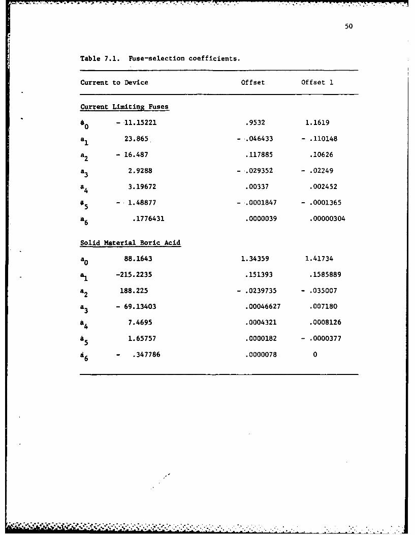
X will be the logarithm of overload current or device number. Table 7.1
lists the various coefficients aj.
After the fuse is selected, it must be coordinated. The program
uses the values of OFSET and OFSET 1 with the applicable fuse curve to
solve for a time value for a set-current value. The program searches
for the load-side device to find the highest time value to that current
value. If the time value Is larger for the size, it is properly coor-
dinated. If not, it increases the fuse size by one, solves for OFSET
and OFSET 1, and tries again continuing until it has found the proper
fuse size.
Relay Selection and Coordination
Relays provide the most difficult coordination problem. First
a turns ratio for the current transformer (CT) must be chosen. The
computer selects the proper tap setting to prevent saturation. It
does this by always selecting the highest turns possible while
selecting the tap setting on the relay as well [12]. The computation
uses a 600/5 CT [13] with tap settings and CO relays [14] with tap
settings. This combination of tap setting for the CT and the relay
combined with the load current establish the pickup point:
Pickup -Log [(Turns Ratio CT x Turns Ratio Relay)] (7.2)
m r u- umu /~ll innke d k k . . . ."""", ' :, ..
50
Table 7.1. Fuse-selection coefficients.
Current to Device Offset Offset 1
Current Limiting Fuses
60-.11.15221 .9532 1.1619
a1 23.865. --.046433 - .110148
a2 - 16.487 .117885 .10626
a3 2.9288 -..029352 - .02249
a 4 3.19672 .00337 .002452
6 - 1.48877 - .0001847 - .0001365
a6 .1776431 .0000039 .00000304
Solid Material Boric Acid
0o 88.1643 1.34359 1.41734
a1 -215.2235 .151393 .1585889
*2 188.225 - .0239735 -. 035007
*3 - 69.13403 .00046627 .007180
a 4 7.4695 .0004321 .0008126
a51.65757 .0000182 -. 0000377
a 6 .347786 .0000078 0

51 77
Since relay curves are in units of multiples of pickup this
pickup value will be used often. Only the relay pickup has been set,
its time dial must be coordinated. Table 7.2 lists the relay-curve
coefficients.
Due to the inverse time shape of a relay curve, many points on
the curve must be checked with its load-side device to insure that
proper coordination exists. The manner in which the family of relay
curves are represented simplifies the problem somewhat. A relay
operating time of 0.4 seconds is assumed throughout. At each current
value, the load-side-device operating tiiae is summed with the relay
operating time. If this time is greater than the line-device time, the
difference is the relay time-delay setting. Thus, when all currents
up to the fault currents are checked, all points on the line-device
curve are at least 0.4-seconds higher than all points on its load-side
device.
Molded Case Circuit Breaker
The molded-case circuit breaker (MCCB) with its different
characteristics provides a different set of problems. The MCCB curve
cannot be represented by one equation. This device has one set of
curves for the thermal element plus another for its magnetic element.
The MCCB used in the program is a General Electric type, K-1200.
Although there is some difference in the curve shape for the current
ratings, 300-1200 A, they are similar enough to be represented as one
type. Each MCCB has one curve corresponding to minimum total clearing
time and a maximum total clearing time.

* - - ~ ~ a . - ~* .. .~-- * ..- .....- ...7- ...7.
52
-4n
p.4 -t iiM u, e0% co co Go -a 0%cS, U, 'T -T 'C Nen, 0 0% in Ull 14
o 1 In i, co r4 en f
Co
-t 0% co m% r-% I, %0'CC Nn 0 fl' 0
N4 -T~ Go 00 P.(cSn oo 0% 0 %C %0 1-49-4 -T N~ 0% -T (n~ Ii,
-w r, Go U, 0% C(n CNU ~r- - r 0% -41 14 %1
o r- 0 Sti~ 0 r- en
0% 0 0 m% N t ~o u. 0 0% N N4
C1 VS, r- ra C4 s4 .4
N4 r-I N4 en r- coU,0% 0 m~ enN S
an U 0 fl% - 0 'Cr- 14 -It Go 'C N4 SM
o ) w co 0 N4 V-I co
p.4 (S4 en -t -t N co
en, r-I s-I 1- co Ch1a 0 P-I 0% SIn 04 r4r 4 CA N1 co r-. N1 SiM
* U -T en V-A %a P-JJr-4 en -T %C fl. 0%0 - -w co 0 r.-T co
0 M. .
%54
P4
f- C n .1n a l
04
0-
A Ico
53
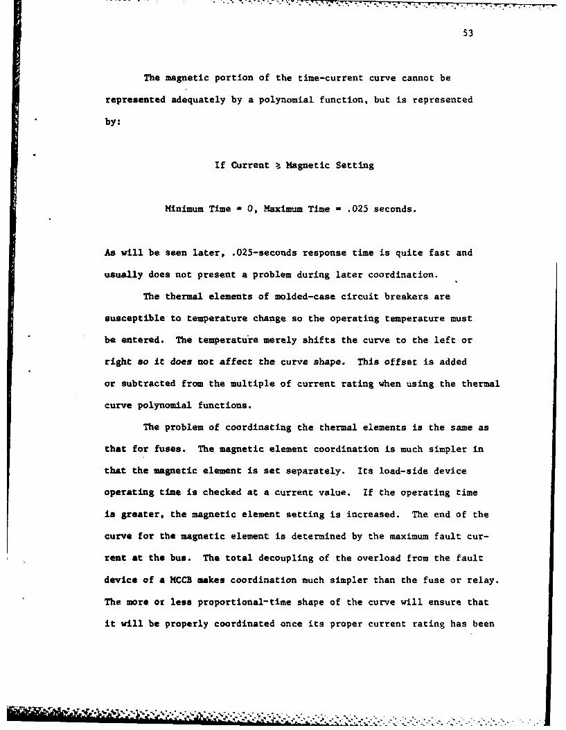
The magnetic portion of the time-current curve cannot be
represented adequately by a polynomial function, but is represented
by:
If Current >, Magnetic Setting
Minimum Time -0, Maximum Time - .025 seconds.
As will be seen later, .025-seconds response time is quite fast and
usually does not present a problem during later coordination.
The thermal elements of molded-case circuit breakers are
susceptible to temperature change so the operating temperature must
be entered. The temperature merely shifts the curve to the left or
right so it does not affect the curve shape. This offset is added
or subtracted from the multiple of current rating when using the thermal
curve polynomial functions.
The problem of coordinating the thermal elements is the same as
that for fuses. The magnetic element coordination is much simpler in
that the magnetic element is set separately. Its load-side device
operating time is checked at a current value. If the operating time
is greater, the magnetic element setting is increased. The end of the
curve for the magnetic element is determined by the maximum fault cur-
rent at the bus. The total decoupling of the overload from the fault
device of a MCCB makes coordination much simpler than the fuse or relay.
The more ot less proportional-time shape of the curve will ensure that
it will be properly coordinated once its proper current rating has been
-.. 9 . .
54
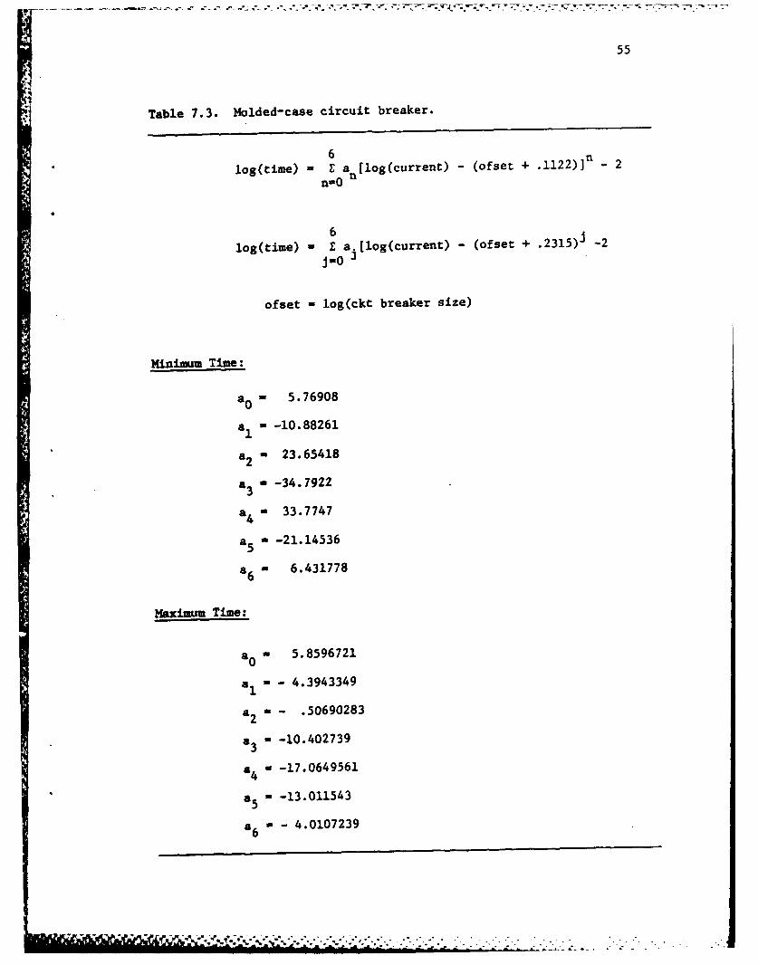
established. Table 7.3 contains the polynomial coefficients used in
the program.
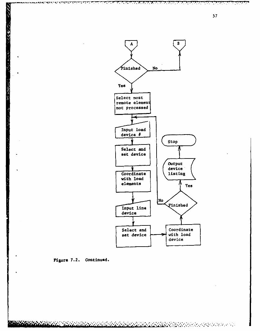
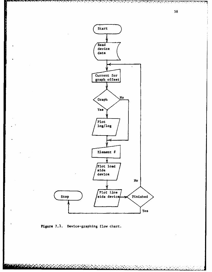
A basic flow chart (Figures 7.2 and 7.3) follows with a complete
program listing in Appendix B.
Suary
In this chaptert the coordination problem was solved to allow
fuses, molded-case circuit breakers, and relays to function so as to
clear a fault in the area of the fault before interrupting the rest of
the distribution system. There is enough flexibility in the program
to allow device settings to be changed and checked using the program
PLDTD.F4. An example problem would be beneficial at this point to'
show how to run the programs. In the next chapter a sample distribu-
tion system will be coordinated using the coordination programs.
55
Table 7.3. Molded-case circuit breaker.
6log(time) -Z a [log(current) - (ofset + .1122)] - 2
nO n
6log(time) - 6 a [log(current) - (ofset + .2 3 1 5)J -2
ofset - log(ckt breaker size)
Minimum Time:
a0 = 5.76908
a, = -10.88261
a2 - 23.65418
a3 - -34.7922
a4 m 33.7747
a5 f -21.14536
a6 - 6.431778
Maximum Time:
a0 = 5.8596721
a1 = - 4.3943349
a2 = - .50690283
a3 = -10.402739
a4 w -17.0649561
a5 a -13.011543
a6 a - 4.0107239

-7 -7-
56
COORD.F
EStartRead loadand
Figre .2. Coodintio flwat .
ut 1
57
Select anCorint
st ldevcihla
g device
Figure .2.iCotinued
Vq-ipu line*.:*................................................
.'*..se device*. wit load0.~'..
* .**. : Select
. * .- * an
Coordinat
* - -. -~ ~ - -. . - -- . - -~ ~ - -* . - -. 777-
58
Start
Readdevice
Figure ~ ~~Crrr 7foeiegapigfo hrt
59
8. OPERATING THE PROGRAMS
General
In this chapter the capabilities, limitations, and use of
the programs will be described. The example system of Figure 8.1
will be coordinated using these programs.
One-Line Diagram
INPUT.F4. All data is entered via the keyboard in the format
detailed in Chapter 3. Data entry is a straightforward process
except when entering transformer data. The program is written for a
"Y-Y" configuration. If one or both sides are "A" configured, then a
large number must be entered for the transformer neutral impedance
"(ZN)" on the bus connected to the A side. After the program is
completed, the zero sequence value for the transformer element con-
taining the transformer may be assigned an arbitrary high value if the
transformer wiring is such that there can be no ground current through
the element. This is done by changing its value in disk file TEST.DAT
(see Appendix C for the file format).
When entering the loads the program asks which type of load
to be entered. The various loads are described as:

60
zi
Y~~ "-- ' .VAA80
4.1kV V
,,
0
4.1kV ~
1-OY .5SMVA 800 /4
4 '7
Figure 8.1. One-line diagram of sample system.
7 , ,.,, 2-'..'."--.."-, . . .- . . -.. .
61
HP - Synchronous motor
HP1 - Assynchronous motor
VA - In KVA
CUR - In amperes
S - No more loads
Load Flow
INPUT.F4. There are no entries from keyboard for this program.
Printing DSK.DAT will provide a load-flow analysis in per-unit values.
Solution of Fault Currents
012
ZBUS.F4. In addition to forming Zbus 1 , this program allows
the input for mutual coupling and for zero-sequence impedance for loads.
Mutual coupling tends to increase fault currents in the mutually coupled
elements and small neutral-to-ground impedances can create higher line-
to-ground fault currents than three-phase faults.
FALT.F4. Besides the solution of fault currents described in
Chapter 6, FALT.F4 also allows the input of fault impedances. This can
provide an interesting study of the system because the user can go
back and place different fault impedances into the fault analysis to
see if the protective devices will operate as desired.
'-_ ,:, . ...................-..-...... ....... .. - . im~ . d .,.€.: ' , . -. . .; : - -?- -?,ii--. '-. . i.-. i. . _..
62
Device Coordination and Plotting
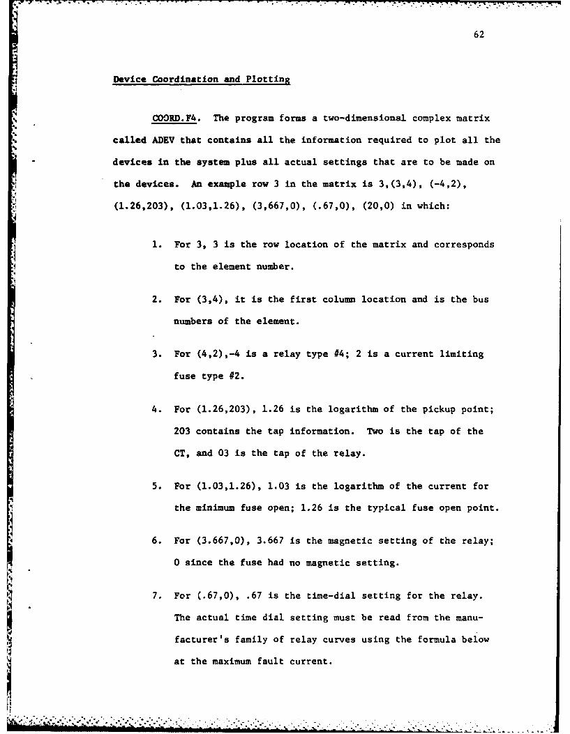
ii COORD.F4. The program forms a two-dimensional complex matrix
called ADEV that contains all the information required to piot all the
devices in the system plus all actual settings that are to be made on
the devices. An example row 3 in the matrix is 3,(3,4), (-4,2),
(1.26,203), (1.03,1.26), (3,667,0), (.67,0), (20,0) in which:
1. For 3, 3 is the row location of the matrix and corresponds
to the element number.
2. For (3,4), it is the first column location and is the bus
numbers of the element.
3. For (4,2),-4 is a relay type #4; 2 is a current limiting
fuse type #2.
4. For (1.26,203), 1.26 is the logarithm of the pickup point;
203 contains the tap information. Two is the tap of the
CT, and 03 is the tap of the relay.
5. For (1.03,1.26), 1.03 is the logarithm of the current for
the minimum fuse open; 1.26 is the typical fuse open point.
6. For (3.667,0), 3.667 is the magnetic setting of the relay;
0 since the fuse had no magnetic setting.
K7. For (.67,0), .67 is the time-dial setting for the relay.
The actual time dial setting must be read from the manu-I. facturer 's family of relay curves using the formula below
at the maximum fault current.

63
time-dial-setting found = (found-time curve)
(time-dial 1/2 setting)
8. For (20,0), 20 is the turns ratio of the current trans-
former.
Device numbers the programs asks for correspond to the
devices below:
1 - Current limiting fuse
2 - Boric fuse high voltage only
3 - Molded-case circuit breaker
4 - Overcurrent relay
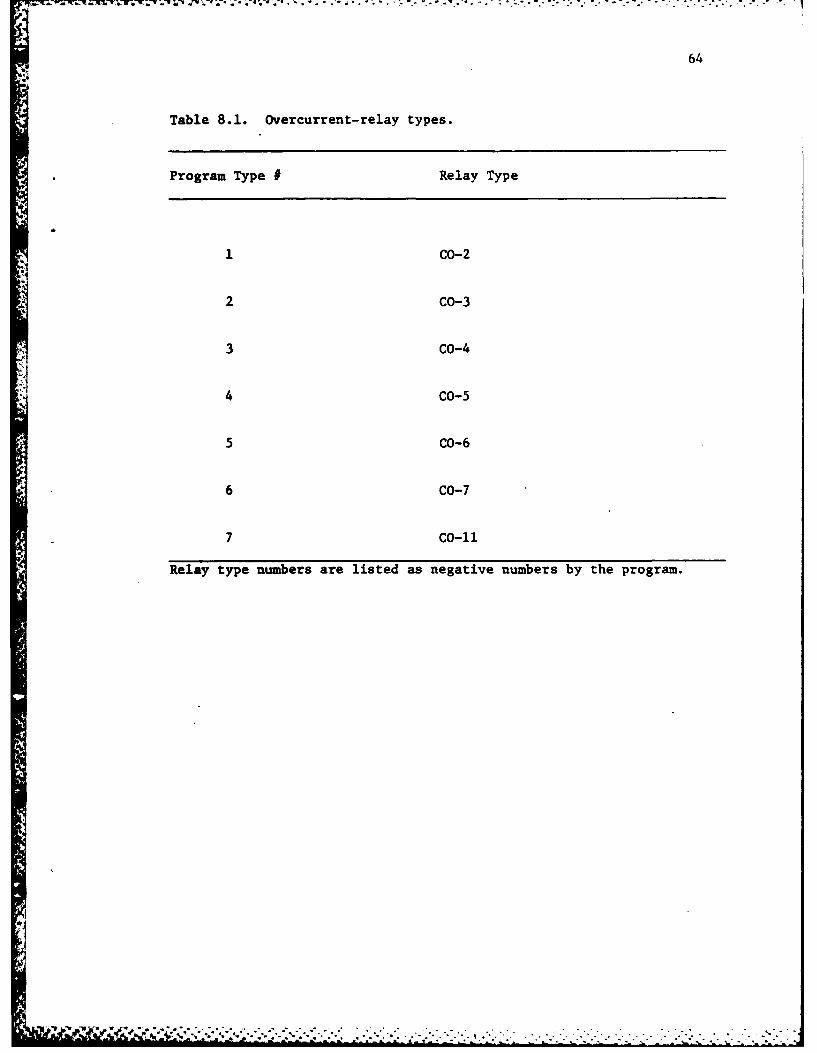
In device 4 the program will ask later what particular type
of relay to use from Table 8.1.
Upon completion of coordination, a device listing is typed
on the keyboard, and a printout of the same is available by typing:
PRINT*. LPT.
When performing the plot having a device listing as well asa
fault current listing is helpful.
PLOTD.F4. This program plots the devices that were coordinated
above. By using a graph, it is possible to visually check coordination.
The program arrangement allows the user to change any device setting
or size in ADEV.DAT to tailor the coordination to his particular require-
ments (see Appendix C for the file format). The program uses the lowest
64
Table 8.1. Overcurrerit-relay types.
*Program Type # Relay Type
1 CO-2
2 CO-3
3 CO-4
4 CO-5
5 CO-6
6 CO-7
*7 CO-li
Relay type numbers are listed as negative numbers by the program.

"7.
65
voltage in the system as a base for plotting currents. The user can
select any plot offset. This has the effect of plotting only the
area of concern. In this way a very detailed graph can be obtained.
Tables 8.1-8.4 provide a listing of program device type numbers
to the actual device type and size.
Table 8.5 details what is contained in the various disk loca-
tions created by the programs.
To coordinate the devices in Figure 8.1, the procedure begins
by entering element data using INPUT.F4. The program asks if data is
to be read from disk or from the keyboard. The first element must be
entered using the keyboard.
The proper procedure is to group the elements to be entered
by wire or cable type as the program only handles one type of wire or
cable at a time. When completed with one type, answer zero for all
other questions and the computer writes the element data that it has
computed on disk in the file RELA.DAT and stops. The new wire type
polynomial coefficients are copied into RES.DAT and the program is
ready to be run for the new wire type.
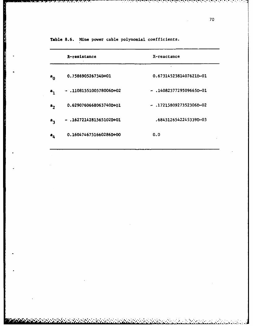
The cable coefficients used in the test problem are for mine
power cable [5]. The coefficients are listed in Table 8.6.
After selecting keyboard, the base power and volts are entered.
The computer then informs the user to begin element data entry. The
data format (Chapter 3) is listed to aid the user. For example, the
element from bus one to two of Figure 8.1 is entered as follows:
1/2/3000/6. For the element containing the 1 MVA transformer the follow-
ing is input: 2/3/35/6/.001.005/l/15/4.1. The bus base -voltages-are
..

66
Table 8.2. Current-limiting fuses.
Program Type # Limiting Fuses
1 5E
2 7E
3 10E
4 15E
5 20E
6 25E
7 30E
8 40E
9 50E
10 65E
11 80E
12 100E
13 .125E
14 150E
15 200E

67
Table 8.3. Boric fuses.
Program Type # Size
*16 15E
17 20E.
18 25E
19 30E
20 40E
21 50E
22 65E
23 80E
24 IO0E
25 125E
26 150E
27 175E
28 200E
29 250E
30 300E
31 400E
32 2-250E
33 2-300E
34 2-400E

68
Table 8.4. Molded-case circuit breakers.
Program # Size
34 300 amps
35 350 amps
36 400 amps
37 450 amps
38 500 amps
39 600 amps
40 700 amps
41 800 amps
42 1000 amps
43 1200 amps

69
Table 8.5. Disc files.
DIGIT. F4: Curve-smoothing program
DEV.F4: Numonics input program
INPUT.F4 Element data-input program
LDFLO. F4: Load-flow program
ZBUS.F4: Formation of ZBUS0 1 2 program
FALT.F4: Solution of fault-current program
COORD. F4: Coordinate device program
PLOTD.F4: Plot device curves
RES.DAT: Contains X/R line coefficients
TEST.DAT: Contains element and load data in per unit
RELA.DAT: Contains element and bus voltage data
XFOR.DAT: Contains transformer inrush and withstand values
LOCUR.DAT: Contains load currents
DEV.DAT: Contains relay coefficients
DSK.XFR: Contains load-flow currents in P.U.
DSK.DAT: Contains load-flow analysis data
ZBUS.DAT: Contains ZBUS01 2
ZBUS.FOR: Contains ZBUS01 2 before loads are added
NUT.CO: Contains mutual coupling data
FALT.DAT: Contains per-unit fault currents
EFLT.DAT: Contains per-unit fault voltages
LCUR.DAT: Contains real values of load-flow currents
FCUR.DAT: Contains real values of fault currents
ADEV.DAT: Contains coordinated-device listing
, ' d - " . . ." " " " " " " " " "6 *.. . . . .. . . .' . -. i ' , .: . ; ' ,'
7. 7 7-7-7 -777 .#. 777..-7%
70
Table 8.6. Mine power cable polynomial coefficients.
R-resistance X-reactance
a0 0. 758690526734D+01 0. 6731452381407621D-01
*1 .1108155100578006D+02 -. 1408237729509665D-01
*2 0.6290760668063740D+ol - .1721580927352306D-02
*3 -. 1627214281565102D+01 .6845126542245339D-03
*4 0.1604746751660286D+00 0.0
I. ' ~ ..- ' . - o- 7 r- -w -r-
71
input next with the voltage in volts. Upon completion of entry of all
bus base voltages, the computer types the computed element value in
per unit. The load data is entered next. The program types the data
entry format for the user. The 50 hp motor is entered as: 8/50/.85.
The only other data to be entered are mutual coupling and zero sequence
load impedance in ZBUS.F4 and fault impedance in FALT.F4. The sample
problem uses no coupling and a fault impedance of zero. COORD.F4 is
run next. The device type desired is entered when asked for by the
program. A sample data input is given in Appendix D.
I' ' "".' -'"-.';-'',-," ,--"." . i. ..- .i.. ... ..-..-

-J"7k , -W 7 --- .- .. .- .- : -'- -
72
The following is a list of load locations and
currents.
Bus number Load current
4 84.03966804 84.03966807 293.66134008 48.9435570
The following is the current flow in the system
under full load conditions as found from the
load flow analysis.
Bus P to Bus Q Current at P Current at Q
1 2 34.2226440 34.22264402 3- 34.2226630 125.20487003 4 88.0372570 88.0372570
3 5 39.1722710 39.17227105 6 39.1721210 365.01295006 7 313.4835700 313.48357006 8 51.6573760 51.6573760
The following is the computed fault currents for a
3 phase fault and a line to ground fault.
Fit Bs P Element 3 Phase Ln to Gnd
2 1 9380.7892000 7053.92980002 2 261.6855700 183.76854002 3 677.8190200 595.45212002 4 280.0413400 187.26861002 5 230.3767000 136.25857002 6 2226.3547000 1496.46060002 7 383.7966900 270.93310003 1 t247.2941000 833.3620700
3 2 1247.2997000 326.25582003 3 846.6523100 699.4013200

73
Fit Bs P Element 3 Phase Ln to Gnd3 4 349.8265800 206.04356003 5 349.7991000 204.29714003 6 2780.8159000 1648.7648000
3 7 479.3659400 302.56822004 1 1017.3596000 469.64384004 2 1017.3546000 466.34913004 3 4003.0938000 2210.28070004 4 285.3238300 121.90246004 5 285.3382800 121.30720004 6 2268.1567000 972.76993004 7 391.0159800 174.01038005 1 881.8973500 308.32957005 2 881.8899900 307.26717005 3 598.6094700 260.16607005 4 3803.2506000 1384.17250005 5 353.1902700 108.59707005 6 2807.5742000 901.2339600
5 7 483.9912400 183.84820006 1 791.2624200 148.92874006 2 791.2645000 148.47739006 3 537.0808000 125.49325006 4 3416.9009000 668.58960006 5 3416.8793000 569.47605006 6 2839.6040000 517.30909006 7 489.5244300 124.55112007 1 350.4617800 103.11314007 2 350.4624900 103.1008700
7 3 237.8819000 70.40414007 4 1513.3939000 445.70089007 5 1513.3895000 443.97709007 6 14273.8630000 4235.39700007 7 216.8161500 64.26732008 1 156.6019600 23.57176408 2 156.6021300 23.54019808 3 106.3009100 16.47665908 4 676.2499600 102.22858008 5 676.2485300 100.18741008 6 561.9951900 84.07306708 7 6769.2755000 1059.3405000
- . C.. *[lli b[ , . , , ' , . - . . , , . .', , . . , , . - -- " - . " '' . .". . " -•
74
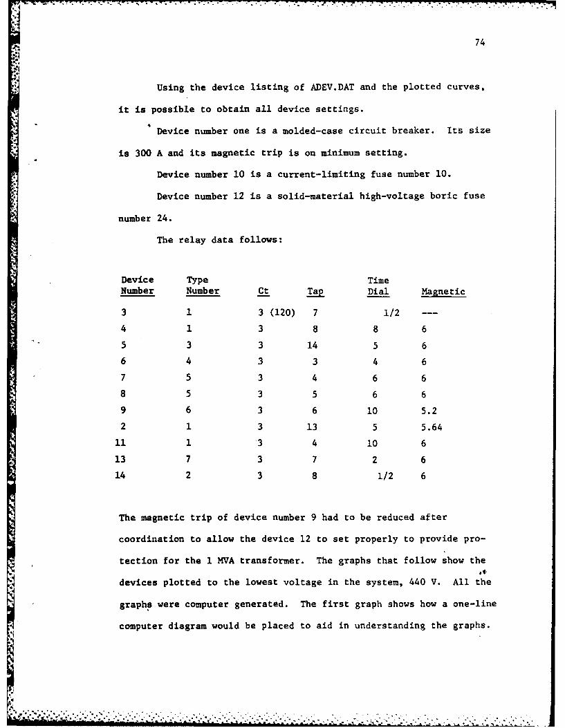
* Using the device listing of ADEV.DAT and the plotted curves,
it is possible to obtain all device settings.
Device number one is a molded-case circuit breaker. Its size
is 300 A and its magnetic trip is on minimum setting.
* Device number 10 is a current-limiting fuse number 10.
Device number 12 is a solid-material high-voltage boric fuse
*number 24.
* The relay data follows:
Device Type Time
Number Number Ct Tap Dial Magnetic
3 1 3 (120) 7 1/2 --
4 1 3 8 8 65 3 3 14 5 6
6 4 3 3 4 6
7 5 3 4 6 6
8 5 3 5 6 6
9 6 3 6 10 5.2
2 1 3 13 5 5.64
11 1 '3 4 10 6
13 7 3 7 2 6
14 2 3 8 1/2 6
The magnetic trip of device number 9 had to be reduced after
coordination to allow the device 12 to set properly to provide pro-
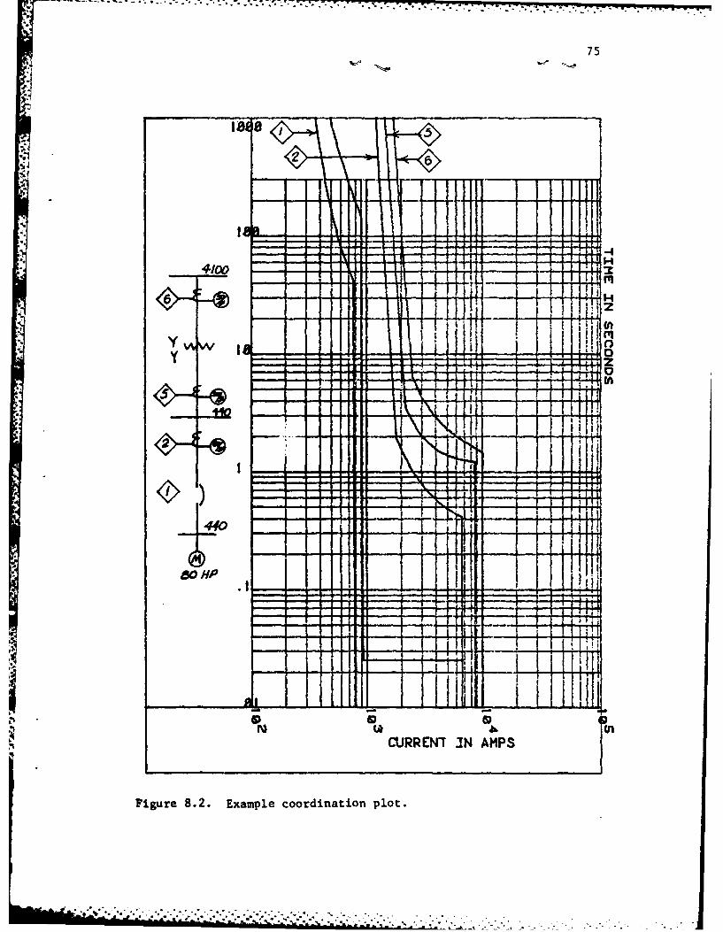
tection for the 1 MVA transformer. The graphs that follow show the
devices plotted to the lowest voltage in the system, 440 V. All the
graphs were computer generated. The first graph shows how a one-line
computer diagram would be placed to aid in understanding the graphs.
75
'A
-9-
4100
Y %&
I~ H 0
so AA
-
-T) I 1H
Qs 46 (nuCJRREN7 IN AMPS
Figure 8.2. Example coordination plot.
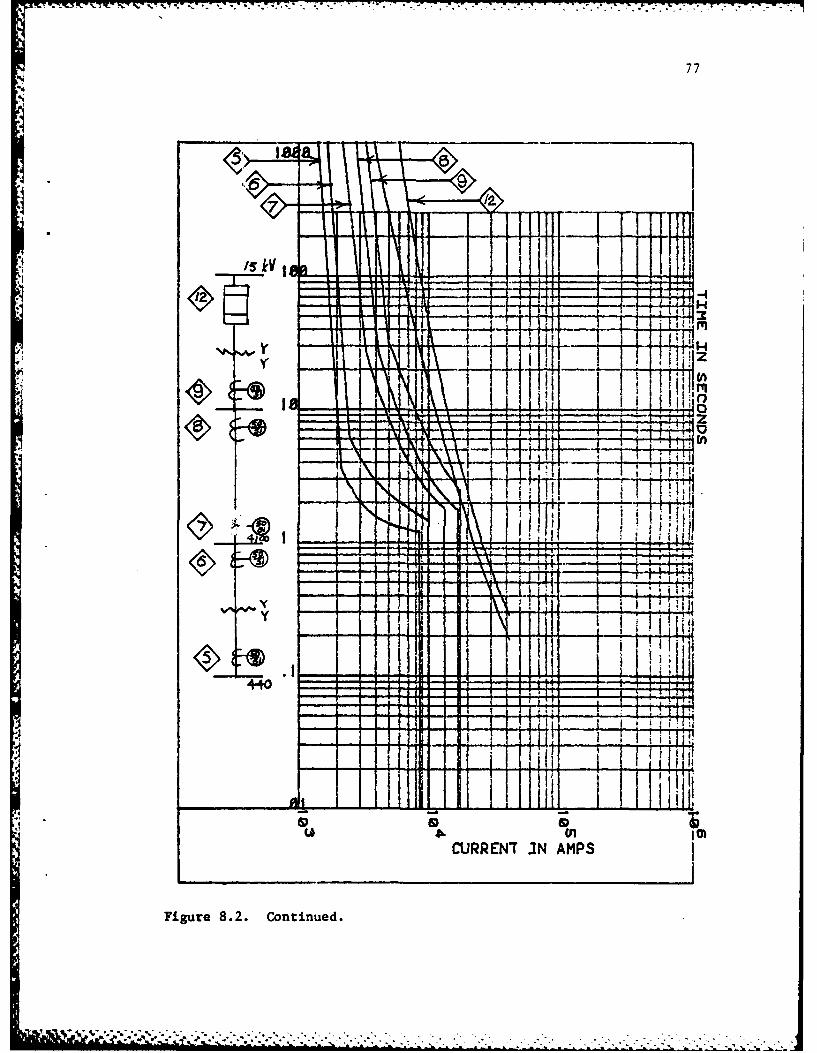
77
%Alii
1:<t>I ~
-1 iL I:ftll 1CURREN7 JN AMPS
Figure 8.2. Continued.

78
jK33
1 I -
I4.1 11 -
~~4q
800 hp.. 4
Li .b
I URN NIXA\P
S.VI
Figure 8.2. continued.

79
Summary
The sample distribution system of Figure 8.1 was coordinated
using the coordination programs. Using the device-plotting program
PLOTD.F4 this coordination was checked to see if the computer generated
coordination was satisfactory to the user.
During the research for this thesis many observations were made
and many features could be added to these programs in the future. This
will be discussed in the chapter that follows.
b ,~ ." ".. . . . . . . . . . . . . . . . .. .
80
9. CONCLUSIONS
In this thesis the author set out to represent a one-line
distribution system in a per-unit system and to solve for three-
phase and line-to-ground faults and to perform a load-flow analysis.
The various protective devices-response curves needed to be represented
by polynomial functions. These requirements were fulfilled using the
methods detailed in Chapters 2-7.
The last task was to develop a computer procedure to coor-
dinate a distribution system's protective devices. Fuses, molded-
case circuit breakers, and relays were coordinated and their coordi-
nation graphs were plotted. There are many extensions for further
york that could be done. These extensions will be discussed later.
While working with the various programs, several observations
have proved useful when performing coordination. Coordination should
not be an afterthought in designing a distribution system. It is
easy to design a system that is impossible to coordinate correctly.
A radial system is easier to coordinate. Moving from a load toward
the source, the time-current curves shift to higher current-time
responses so that when finally arriving at a transformer, providing
proper transformer protection and coordination simultaneously may be
impossible.
Coordination of the thermal-tripping elements of molded case
circuit breakers is very difficult due to the difference between'the
minimum and maximum tripping time curves. Coordination of these

81
devices is best done manually with some overlap of the thermal time
curves. The magnetic elements could then be adjusted to provide
* proper fault coordination. Those manually adjusted devices can be
added to ADEV.DAT and be checked using PLOT.F4.
In systems with different voltages, the transformers should be
of different sizes so that the smaller sizes are on the load side.
This will allow proper coordination and protection. Relays are
preferable to other types of protection on the high-voltage parts
of the system in that their response can be controlled.
Recommendations for Further Work
1. Using an analog computer and the programs presented here,
an entire distribution and generation system could be
looked at in detail. A transient-stability study would
show the effezt of various device settings.
2. The INPUT.F4 program could be enlarged to automatically
account for different transformer configurations.
3. Additional devices could be added easily to the program.
The program allows up to twenty different relay types. The
additional coefficient data is merely entered in disk
DEV.DAT. Additional molded-case circuit breakers would be
slightly more difficult in that it would require some program
modification.

82
4. The plotting program could be enlarged to include drawing
a one-line diagram in the space provided and adding other
data directly on the graph.
5. The program could be expanded for the case of having one
device in an element.
-L O. . .. . . . . -.-.. . . . .

- air.'-r.-w - --. ' w -. . W -W r r .-- L .r-U -
83
REFERENCES
1. Wagner, J. K., "Interactive Mine Power System Relay Coordination,"M.S. Thesis, The Pennsylvania State University, 1980.
2. Radke, G. E., "A Method for Calculating Time Overcurrent RelaySettings by Digital Computer," IEEE Transactions on PowerApparatus and Systems, Vol. PAS-82 Special Supplement (1965):189-205.
3. Albredt, R. E., NisJa, M. J., Feero, W. E., Rockeffeller, G. D.,and Wagner, C. L., "Digital Computer Protective Device Coordi-nation Program I-General Program Description," IEEE Transactionson Power Apparatus and Systems, Vol. PAS-83 (April 1964):402-410.
4. Langhans, J. D. and Ronat, A. E., "Protective Devices Coordinationvia Computer Graphics*," Proceedings of IEE Industry ApplicationsSociety Annual Meeting, October 1979, pp. 1209-1217.
5. Mining Cable Engineering Handbook, The Anaconda Company, 1977.
6. "Engineering Dependable Protection for an Electrical DistributionSystem," Bussuan Manufacturing Division, McGraw-Edison Company,1968.
7. Wagner, C. F., Evans, R. D., Symetrical Components, New York,McGraw-Hill, 1975.
8. Stevenson, W. D., Elements of Power System Analysis, New York,McGraw-Hill, 1933.
9. "NUMONICS Electronic Graphics Calculator," The PennsylvaniaState University, Hybrid Computer Laboratory, 1976.
10. "Scientific Subroutine Package," Function "MINV," White Plains,New York, International Business Machines Company.
11. IEEE Recommended Practice for Protection and Coordination ofIndustrial and Commercial Power Systems. IEEE, 1975.
12. Stagg, G. W. and El-Abiad, A. H., Computer Methods in PowerSystam Analysis, New York, McGraw-Hill, 1968.
- V V N 9
..
84
13. Morley, L. A., Mine Power Systems, Vol. I, II, Bureau of Mines,1981.'
14. "Type Co (HiLo) Overcurrent Relay," Westinghouse I.L. 41-100B,1976.
15. "Molded Case Circuit Breaker Ges GlllB," General Electric.
MEN --*~ -~-w -. - -.. . . . . . . . . -.. . . . . .

85
APPENDIX A
CURVE -SMOOTHING PROGRAMS
- -1W.TrTIM,.2' ITT 7-0.77rr
86
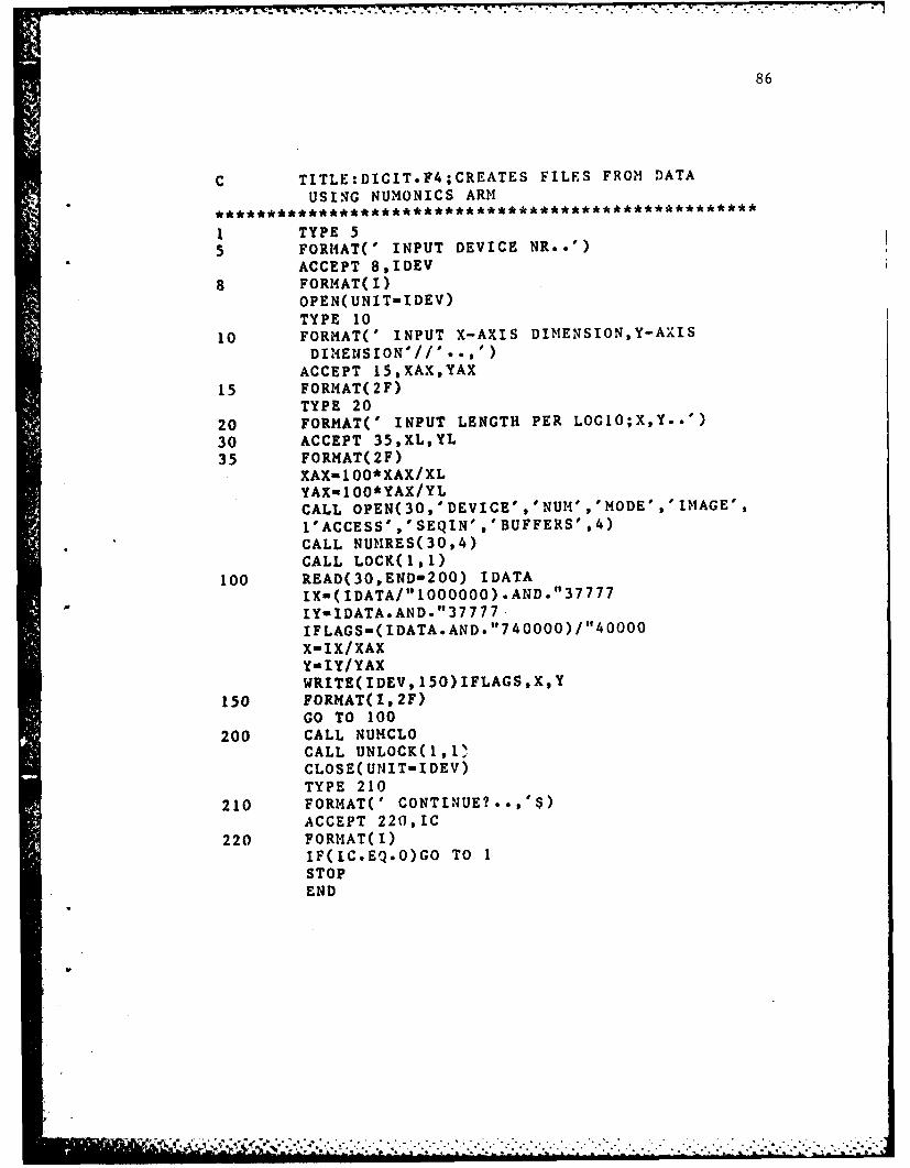
C TITLE:DIGIT.F4;CREATES FILES FROM DATAUSING NUI4ONICS ARM
I TYPE 55 FORIAT(' INPUT DEVICE NR..')
ACCEPT 8,IDEV
8 FORMAT(I)OPEN( UNIT-IDEV)TYPE 10
10 FORMAT(' INPUT X-AXIS DIMENSION,Y-AXISDIMEffSION'//' - x')
ACCEPT 15,XAX,YAX
15 FORMAT(2F)TYPE 20
20 FORMAT(' INPUT LENGTH PER LOGLO;X,Y..')
30 ACCEPT 35,XL,YL35 FORMAT(2F)
XAX 100*XAX/XLYAX-1 00*YAX/YLCALL OPEN(3O,'DEVICE','NUM-','MODE','IM1AGE',1'ACCESS',.1SEQIN' ,'BUFFERS' ,4)CALL NUMRES(30,4)CALL LOCK(11)
100 READ(30,END-200) IDATAIXi(IDATA/"1000000).AN4D. "37777IY-IDATA.AND. "37777IFLAGS""(IDATA.AND. "740000)/"40000X-IX/XAXY-IY/YAXWRITE(IDEV, 150)IFLAGSXY
150 FORMAT(I,2F)GO TO 100
200 CALL NUIICLOCALL UNL0CK(1,1",CLOSE(CUNIT-IDEV)TYPE 210
210 FORMAT(' CONTINUE?..,$ACCEPT 220,IC
220 FORMAT(I)IF(IC.EQ.O)G0 TO ISTOPEND
87
C CURVE FITTING PROCRAII:DEV.F4
INTEGER L(7),14(7)REAL X(100),YS(1OO)REAL*8 YM( 100) ,G(7 ,7) ,iJ(7) ,A(O/6) ,GG(7 ,7) ,ERROR( 100)TYPE 100
100 FORMAT(1X,'CHOOSE DIMENSION OF FIT')ACCEPT 110,ND
110 FORMAT(I)TYPE 120
4120 FORMAT(1K,'CI{OOSE NO. OF POI1NTS '$)ACCEPT 110,M4TYPE 130
130 FORMAT(/ CHOOSE INPUT FILES'/' ..
ACCEPT 110,IUNITIDO 140 I-1,MREAD(IUNITL,135)J,X(I),YS(I)
135 FORMAT(I,2F)YS( I)-ALOGIO(YS( I))
140 CONTINUEDO 10 K-l,MDO 10 I-1,ND
DO 10 J-1,ND
10 CONTINUECALL DMINV(G,7,ND)DO 20 I-0,ND-1DO 20 J-1,NDA(I)inA(I)+G(I+1,J)*U(J)
20 CONTINUEDO 30 1-1,MDO 30 J-0,ND-1YM(l)-YM(I)+A(J)*X(I)**J
30 CONTINUEDO 40 1-1,M
40 SQUERRiSQUERR+(YS(I)-YM(I))**2TYPE 160,SQUERR
160 FORM4AT(' THE INTERGRAL-SQUARED ERR~OR IS: 0',E)OPEN(UNIT-40,FILE-'A.DAT')WRITE(40, 170)ACLOSE( UNIT-40)
170 FORMAT(D)TYPE 99,IUNIT1
99 FORIIAT(' IUNIT-'*I)DO 50 I-I'm
50 ERROR( I)-DABS( (YH%( I)-YS( I)) /YS( I))OPEN(UN1lTa4l,FILE-'YINOUT.DAT')WRITE(41,18O)(X(I),YS(I),YMt(I),E-ROR(I),1=1,M1)
180 FORM*AT( 2F, 2D)
88
CLOSE( UNIT-4 1)STOPE ND
C TITLE:DMINV;SUBROUTINE TO INVERT A REAL SQUAREMATRIX DOUBLEC PRECISION
SUBROUTINE DMINV(A,MDIM,N)REAL*8 A(MD1M,N)INTEGER L(100),M(100)
CC CONVERTED FROM SSP ROUTNE MINVC
DOUBLE PRECISION BIGA,HOLDDO 80 K-1,NL( K)aK
M(K)-KBIGA-AC K,K)DO 20 J-K,NDO 20 I-K,N
10 IF( DABS( BIGA)-DABS( A( I, ))) 15,20,2015 BIGA-A(I,J)
L(K)..I14 (K )-3
20 CONTINUEJ-L(K)IF(J-K) 35,35,25
25 DO 30 1-1,14HOLD--A(K, I)A(K, I).'A(J,I1)
30 A(J,I)-HOLD35 1-14(K)
IF(I-K) 45,45,3838 DO 40 J-1,N
HOLD--A( J ,K)A(J,K)-A(J, I)
40 A(J,I)-HOLD45 DO 55 1-1,N
IF(I-K) 50,55,5050 A(I,K)-A(I,K)/(-BIGA)55 CONTINUE
DO 65 1-1,NHOLD-A( I,K)DO 65 J-1,NIF(I-K) 60,65,60
60 IF(J-K) 62,65,6262 A( I,J)-HOLD*A(K,J).A( 1,3)65 CONTINUE
DO 75 J-1,NIF(J-K) 70,75,70
70 A(K,J)-A(K,J)/BIGA75 CONTINUE

89
A(K,K)-(1.0000000)/BICA
80 CONTINUEK-N
100 K-K-iIF(K) 150,150,105
105 I-L(K)IF(I-K) 120,120,108
*108 DO 110 J-1,NHOLD-A( JK)
A(J , K)--A( 3,I)
110 A(J,I)-HOLD
120 J-M(K)IF(J-K) 100,100,125
125 DO 130 1-1,NHOLD-A(K, I)A( K, I )--A(J I,1
130 A(J,I)-HOLDGO TO 100
150 RETURNEND
AD-A1l34 05 A COMPUTATIONAL PROCEDURE FOR THE PROTECTION OF 2/2INDUSTRIAL POW1ER SYSTEMS(U) EENNSYLVANIA STATE UNIVUNIVERSITY PARK DEPT OF ELECTRICAL ENGINEERING
UNCLASSIFID C N SALNOND NOV 81 F/G 18/2 , N
EhhmohEohmoliEEhmhhEmhEmhmhE
EL
11111 ,__o 128
Lllla E 2 IJ32
1111&8El1.25 1 1 6
MICROCOPY RESOLUTION TEST CHARTNATIONAL BUREAU OF STANDARDS-1963-A
'*i% --
. *S, ,% -t* w -
T7 9 K
90
APP'ENDIX B
COORDINAT ION AND PLOTTING PROGRAMS

- - . -|. .- w I*. . .-.. . .
91
*************************************************** ****
C INPU'T.IT INPUTS DATA FROM A TERMINAL,PLACES INC THE PROPER FORMAT FOR OTHER PROGRAMS********************************* ** * ** ******
Cc
DIMENSIONL(30,30,2),PU(30,30,I),RES(30,30,2),E(30),XL(30,30,2)
DIMENSIONS(300),ZER(30,30,2),RC(7),XC(7),ZG(30),XD(30)
COHPLEX Tl,TPU,PU,S,S1 ,PUI ,PZ,CUR,ZER,ZGREAL*8 A(7),AA(7)REAL L******************** * *** ** *** ** * ****** **** *** *
C IF THE PROGRAM HAS ALREADY BEEN RUN ONCE ALL DATAC NEED NOT BE ENTERED AGAIN
TYPE 33 FORMAT(' DO YOU WANT TO READ DATA FROM A FILE ORFROM KYBRD?'/
2' <CR>FOR INPUT FROM TTY,1 FOR READ...')ACCEPT 11.,IIF(I.NE.O)GO TO 400
C INPUT OF DATA ON LINES
TYPE 55 FORMAT(2X,'ENTER THE PROBLEM BASE IN MVA')
ACCEPT 10,ZBASETYPE 6
6 FORMAT(2X,'ENTER THE PROBLEM BASE IN KV')ACCEPT 10,EBASE
10 FORMAT(F)11 FORMAT(I)
GO TO 14
C PROGRAM RETURNS HERE AFTER READING DATA AT 400
12 TYPE 1313 FORMAT(' OLD DATA IS ENTERED,READY FOR N EW LI'EDATA..')
ACCEPT 11,114 TYPE 1515 FORHAT(/,2X,'ENTER ELEMENT DATA ASFOLLOWS: BUS( )TO( ) (LENGTH)
I (SP)SIZE',/,2X, '(TRANSFORMERIHPEDENCE(P.U.))(TRANSFOR!4ER SIZE
21N MVA) SP',/, 2X,'(TRANSFORIIER !IGIl VOLTAGE IN KV)SP' /,
3(TRANSFORMER LOW VOLTAGE IN KV)...,'/)********************************** **** *** *** *********** *
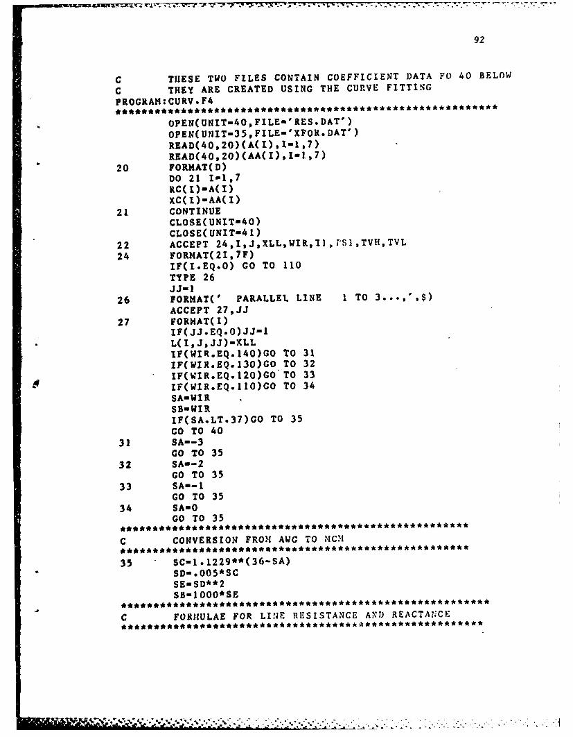
7-X-- .k x .T-
92
C THESE TWO FILES CONTAIN COEFFICIENT DATA FO 40 BELOW
C THEY ARE CREATED USING THE CURVE FITTING
PROGRAM:CURV.F4
* OPEN( UNIT-40, LE-RES.*DAT')OPEN(UNIT=35,FILE''XFOR.DAT')READ(40,20)(A(I),I""1 7)
READ(40020)(AA( I) .1-i,7)20 FORMAT(D)
DO 21 1-1,7RC( I)-A(I)XC(I)-AA(I)
21 CONTINUECLOSE(UNIT-4O)CLOSE( UNIT-4 1)
22 ACCEPT 24,1,JXLLWIR,1I,T1.ITVHTVL24 FORMAT(21,7F)
IF(I.EQ.O) GO TO 110TYPE 26JJ- I
26 FORMAT(' PARALLEL LINE 1 TO 3*..,',$)ACCEPT 27,JJ
27 FORMAT(I)IF(JJ.EQ.O)JJ-1L(I,JJJ)u'XLLIF(WIR.EQ.140)GO To 31IFCWIR.EQ.130)GO TO 32IF(WIR.EQ.120)GO TO 33IF(WIR.EQ.110)GO To 34SA-WIRSBIIIRIF(SA.LT.37)GO TO 35GO TO 40
31 SA--3GO TO 35
32 SAin-2GO TO 35
33 SA-GO TO 35
34 SAmOGO TO 35
C CONVERSION FRO-% AWO TO 'IC1l
35 SC-1.1229**(36-SA)SDm. 00 5*SCSEmSO**2SB-I OOO*SE
C FORIIULAE FOR LINE RESISTANCE AND) REACTANCE
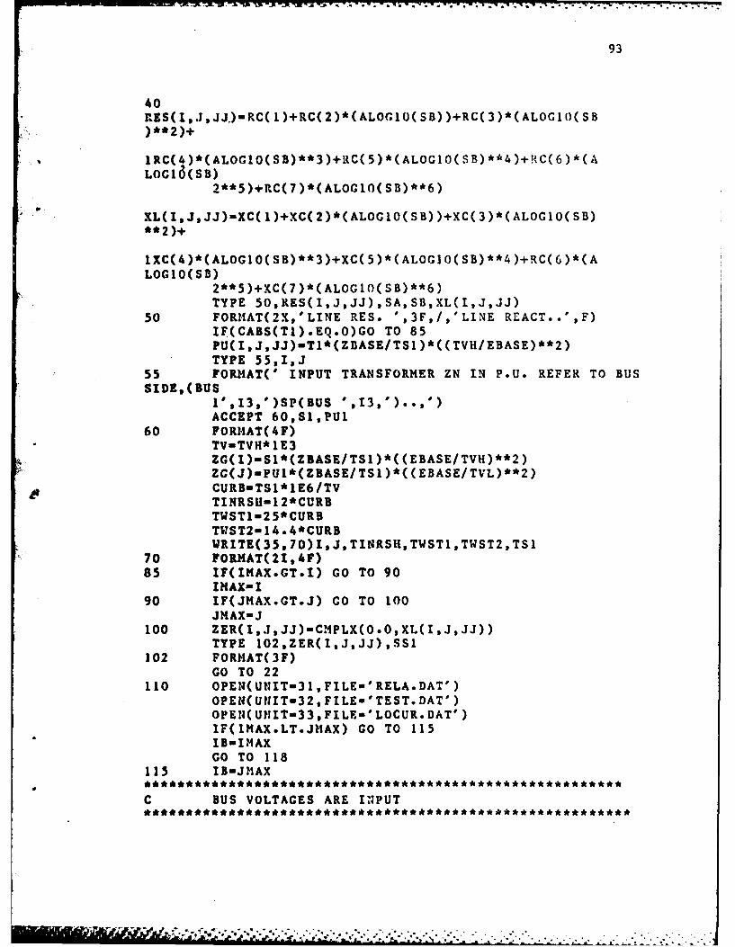
93
40RES(I,JI,JJ.)-RC( I)+RC( 2)*(ALOG1O( SB) )+RC( 3)*(ALOGIO( SB
IRC(4)*(ALOCLO(SB)**3)+RC(5)*(ALOGIO(SB)**4)+{C(6)*(ALOClc3(SB)
2**5)+RC(7)*(ALOG10(SB)**6)
* XL(IJ,JJ)-XC(1)+XC(2)*(ALOGIO(SB))+XC(3)*(ALOGIO(SB)
IXC(4)*(ALOGIO(SB)**3)+XC(5)*(ALOGIO(SB)**4)+RC(6)*(ALOGIO( SB)
2**5)+XC(7 )*(ALOGIO(SB)**6)TYPE 50,RES(I,J,JJ) ,SA, SB,XL(I,J,JJ)
50 FORIIAT(2X.,'LINE RES. ',3F,/,'LINE REACT..',F)IF(CABS(TI).EQ.0)GO TO 85PU(IJJJ)mTI*(ZBASE/TS1 )*((TVH/EBASE)**2)TYPE 55,I,J
55 FORMAT(' INPUT TRANSFORMER ZN IN P.U. REFER TO BUSSIDE, (BUS
l'*13,')SP(BUS '1,).'ACCEPT 60,Sl,PUl
60 FORMAT(4F)TV-TVI E3ZG(I)mSl*(ZBASE/TSI)*((EBASE/TVH)**2)ZG(J)-PUl*(ZBASE/TSI)*((EBASE/TVL)**2)CURB-TS1*1E6/TVTINRSH-1 2*CL'RBTW ST 1-25 *CURBTWST2-14.*4*CURBWRITE(35,70)I,J,TINRSH,TWSTI,TWST2,TSI
70 FORMAT(21,4F)85 IF(IMAX.GT.I) GO TO 90
IMAX-I90 IF(JIIAX.GT.J) GO TO 100
JMAX-J100 ZER(I,JI,JJ)-CMPLX(O.O,XL(I,J,JJ))
TYPE 102,ZER(I,J,JJ),SSI102 FORI4AT(3F)
GO TO 22110 OPEN(UNIT-31,FILE-'RELA.DAT')
OPEII(Ut1T32,FILE-'TEST.DAT')OPEN(UtNIT-33,FILE-'LOCUR.DAT')IF(IYIAX.LT.JHAX) GO TO 115I B-IMNAXGO TO 118
115 IB-JMAX
C BUS VOLTAGES ARE INPUT
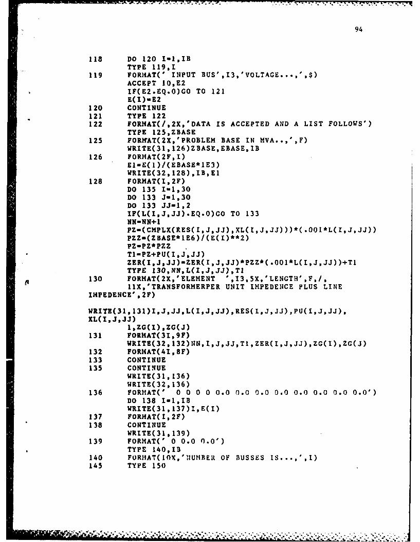
94
118 DO 120 I-1,IBTYPE 119,1
119 FORM4AT(' INPUT BUS',13,'VOLTAGE...... $)ACCEPT 10,E2IF(E2.EQ.O)GO TO 121E(I)-E2
120 CONTINUE121 TYPE 122122 FORIAT(/,2X,'DATA IS ACCEPTED AND A LIST FOLLOWS')
TYPE 125,ZBASE125 FORNtAT(2X,'PROBLEM BASE IN MVA..,',F)
WRITE(31 ,126)ZBASE,EBASE, lB126 FORMAT(2F,I)
El-E( 1)/(EBASE*1E3)WRITE(32, 128) ,IB,EI
128 FORMAT(I,2F)DO 135 1-1,30DO 133 J-1,30DO 133 JJ-1,2IF(L(I,J,JJ).EQ.O)GO TO 133NN-NN+lPZm(CMPL2(RES(IJ,JJ),XL(I,J,JJ)))*(.OO1*L(I,J,JJ))PZZ-(ZBASE*1E6)/(E( I)**2)PZ-PZ*PZZT1-PZ+PU(IJ,JJ)ZER(I,J,JJ)-ZER(I,J,JJ)*PZZ*(.001*L(I,JJJ))+TITYPE 130,NN,L(I,J,JJ),Tl
130 FORMAT(2X,'ELEMENT ',13,5X,'LENGTH',F,/,l1X,'TRANSFORMERPER UNIT IMPEDENCE PLUS LINE
IZIPEDENCE' ,2F)
WRITE(31,131)1,J,JJ,L(I,J,JJ),RES(I,J,JJ),PU(1,J,JJ),XL(I,J,JJ)
1,ZG(I) ,ZC(J)131 FORHAT(31,9F)
132 FORI4AT(41,8F)133 CONTINUE135 CONTINUE
WIRTE(31, 136)WRITE(32, 136)
136 FORMAT(' 0 0 0 0 0.0 0.0 0.0 0.0 0.0 0.0 0.0 0.0')DO 138 I-1,IBWRITE(31 ,137)I,E(I)
137 FORMAT(I,2F)138 CONTINUE
WRITE( 31, 139)139 FORMAT(' 0 0.0 0.0')
TYPE 140,13140 FORFIAT(10K,'1NUMBER OF BUSSES IS...... 1)145 TYPE 150

95
150 FORMAT(//' NOW ENTER THlE LOAD DATA IN THE FOLLOWINGMANNER;...,SS MA I V)PRFCTR . R.
2"/' (BUS ) (LOAD IN KVA)(PWR FACTOR).... OR...'
3'(BUS )(LOAD IN AMPS)(PWR FACTOR)')
Do 300 N-1,IBTYPE 160
160 FORMIAT(' WHAT METHOD WILL YOU USE
?..VA,HP,OR AMPS??')4;
ACCEPT 162,MD
162 FORMAT(A4)TYPE 164,MD
164 FORMAT(22C,A4,' ENTER...'IF(MD.EQ.'HPI') GO TO 170IF(MD.EQ.'HP') GO TO 170IF(MD.EQ.'AMPS') GO TO 180IF(MD.EQ.'S') GO TO 305HD-'VA'ACCEPT 165, J,ASI,PFAC
165 FORMAT(Is2F)SZTZ-AS1/(ZBASE*1E3)SZR-SZTZ*PFACPCOS-ACOS( PFAC)SZI-SZTZ*SIN( PCOS)S(J)-CIIPLX(SZR, SZI)AI-AS1*1E3/(E(J)*SQRT(3.O))WRITE(33, 168)J,AI
168 FORMAT(IF)S T-HDGO TO 300
170 ACCEPT 175,I.PRHPFAC175 FORMAT(I.3F)
SZTZUPRH*74A6SZR-SZTZ*PFACPCOS-ACOS( PFAC)SZI-SZTZ*SIN(PCOS)S(I)-CHPLX(SZR, SZI)/(ZBASE*1E6)
AI-SZTZ/(SQRT(3.O)*E( I))WRITE(33,178)I .AI
178 FO1RMAT(I,)ST-MDGO TO 300
180 ACCEPT 185,I,CURT,PFAC185 FORMAT(1,3F)
WRITE(33, 187)I,CURT
187 FORZIAT(1,F)CURR-CURT* PFACPCOSwACOS( PFAC)CURI-CURT*SIN( PCOS)
Y -- .. ,. . . - . .J

96
CUR-CMPLX( CURR, CURI)CUR-CUR*(SQRT(3.O)*EBASE/ZBASE)S( I)-3*EBASE*CONJG( CUR)/SQRT(3 .0)ST -MD
*300 CONTINUE305 DO 320 N-I,IB
310 FOMAT('TYPE 310,N,S(N),MD310 FRMATUBUS ',13,2F,A4,2F)
WRITE(31,*312)NN, S(NN)312 FORMAT(I,2F)
WRITE(32,315)N,S(N),XD(NN)315 FORMAT(I,3F)320 CONTINUE
WRITE(31 .330)WRITE(32,331)
330 FORMAT(' 0 0.0 0.0')331 FORMAT(' 0 0.0 0.0')
WRITE(33,332)332 FORMAT(' 0 0.0')
WRITE(35, 335)335 FORMAT(' 0 0 0.0 0.0 0.0 0.0 '
GO TO 900400 OPENv(UNIT-36,FILE."'RELA.DAT')
READ(36,411) ZBASE,EBASE,IB* IlAX-IB
411 FORMAT(2F,I)* 450 READ(36,456)I,J,JJ,XL3,RES1,PUL ,XL2,Ti ,S1
456 FORHAT(31.9F)IF(t.EQ.O)GO To 470L(I,J,JJ)'mXL3RES(I,J,JJ)-RESIPU( 1, J, 1)-PU IXL(I,J,JJ)-XL2ZER(I,J,JJ)-CMPLX(O.O,XL2)ZG(I)-TlZG(J)-S1IF(I.NE*0)GO TO 450
470 READ(36,472)I,E(I)472 FORH1ATI,2F)
IF(IoNE.0) GO TO 470457 READ(36,458)1,Sl458 FORMAT(I,2F)
S(I)aS1IF(IoNE.0) GO TO 457REWIND 36JJ-0CLOSE(UNIT'.36)GO TO 12
900 CLOSE(UNIT-31)CLOSE(UNIT-32)
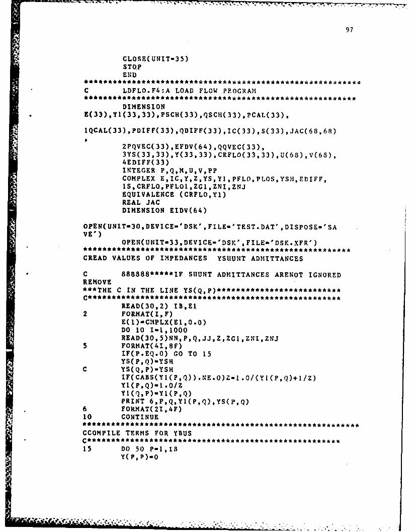
97
CLOSE(UNIT-35)STQPEND
C LDFLO.F4:A LOAD FLOW PROGRAM
DIMENSIONE33) ,Y1( 33, 33) ,PSCH( 33) *QSCII( 33) ,PCAL( 33),
1QCAL(33),PDIFF(33),QDIFF(33),IC(33),S(33),JAC(68,68)
2PQVEC( 33) ,EFDV(64) ,QQVEC( 33),3YS( 33,33) ,Y(33, 33) ,CRFLO( 33, 33),U1(68) ,V(68),4EDIFF(33)INTEGER P,Q,M,UV,PPCOMPLEX E,IC,Y,Z,YS,Y1 ,PFLO,PLOS,YSH,EDIFF,IS,CRFLO,PFLO1 ,ZGL ,ZNI,ZNJEQUIVALENCE (CRFLO,Y.)REAL JACDIMENSION EIDV(64)
OPEN(UNIT-30.DEVICE-'DSK',FILE-'TEST.DAT',DISPOSE-'SAVE')
OPEN(UNIT-33,DEVICE-'DSK',FILE-'DSK.XFR')
CREAD VALUES OF IMPEDANCES YSIIUNT ADMITTANCES
C 888888*****IF SHUNT ADNITTANCES ARENOT IGNOREDREMOVE***THE C IN THE LINEYSQ)*************
READ(30,2) IB,E12 FORMAT(I,F)
E( 1)-C.%PLX(El .0.0)DO 10 1-1,1000READ(30,5)NN,P,Q,JJ,Z,ZGI,ZNI,ZNJ
5 FORMAT(41,8F)IF(P.EQ.O) GO TO 15YS( P,Q)-YS
C YS(Q,P)-YSHIF(CABS(Y1(P,Q)).NE.O)Zu1.0/(YI(P,Q)+1/z)Y1(P,Q)-I .OIZYI(Q,P)-Y1(P,Q)PRINT 6,P,Q,YI(P,Q) ,YS(P,Q)
6 FORMAT(2I,4F)10 CONTINUE
CCOMPILE TERMS FOR YBUS
15 DO 50 P-1,IBY( PP)-O
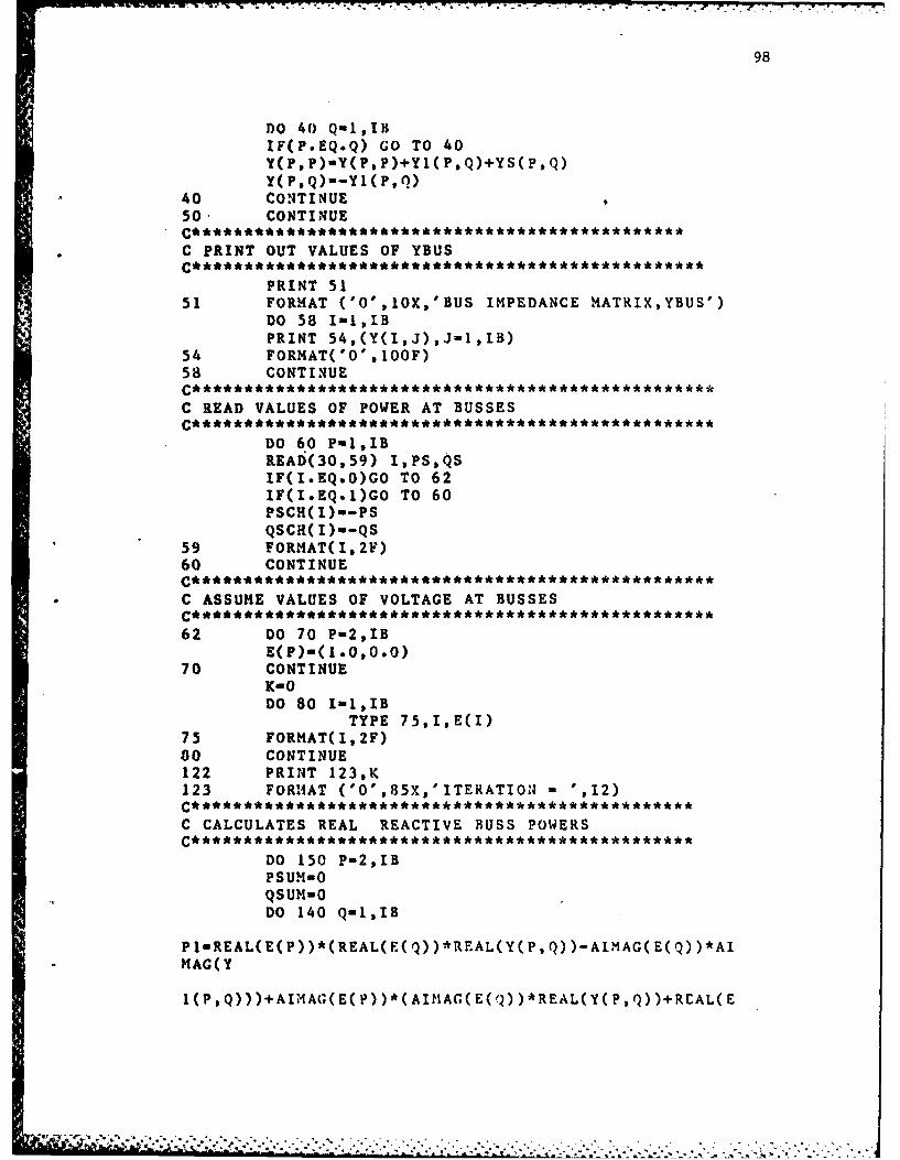
98
DO 40 QUL,II$IF(P.EQ.Q) GO TO 40(, P )-Y( F, P)+Y1( P, Q)+YS(P ,Q)
Y(P.Q)--Y1(P,l)40 CONTINUE I50- CONTINUE
* C PRINT OUT VALUES OF YBUS
PRINT 5151 FORMAT ('O',I0X,'BUS IMPEDANCE MATRIX,YBUS')
DO 58 I-1,IBPRINT 54,(Y(I,J),J=1,IB)
54 FORMAT('O',IOOF)58 CONTINUE
C READ VALUES OF POWER AT BUSSES
DO 6 0 P-1,IBREAD(30,59) I,PS,QSIF(I.EQ.O)GO TO 62IF(I.EQ.1)GO TO 60PSCH( I)--PSQSCR( I)--QS
59 FORMAT(I,2F)60 CONTINUE
* C ASSUME VALUES OF VOLTAGE AT BUSSES
62 DO 70 P-2,IBE(P)-( 1.0.0.0)
70 CONTINUEI(-0DO 80 I-1,IB
TYPE 75,I,E(I)75 FORMAT(1,2F)80 CONTINUE122 PRINT 123,K123 FORMIAT ('O',85X,'ITERATION -',12)
C CALCULATES REAL REACTIVE BUSS POWERS
DO 150 P-2,IBPSUN- 0QSUM- 0DO 140 Q-1,IB
PI-REAL(E(P))*(REAL(E(Q))*REAL(Y(P.Q))-AIMAG(E(Q))*AI?IAG(Y
1(P,Q)))+AI-MAG(E(P))*(AliMAG(E(Q))*REAL(Y(P,Q))+REAL(E

99
2AII4AG(Y(PQ)))
QI-AI4AG(E(P))*(REAL(F(Q))*REAL(Y(P,Q))-AIMAG(E(Q))*A114AG(Y
1(PQ)))-REAL(E(P))*(AIMAG(E(Q))*REAL(Y(P,Q))+REAL(E(Q))*Al
2MAG(Y(P,Q)))PS UN-PS UM+P1QSUl4-QSUM+Q 1
140 CONTINUEPCAL(P)-PSUMQCAL( P)-QSUMPRINT 145,PCAL(P),QCAL(P)
145 FORMAT(2F)150 CONTINUE
C PRINT OUT VALUES OF CALCULATED BUSS POWERS
PRINT 155,K(155 FORMAT('O','REAL AND REACTIVE BUSS POWERS K-',12)
DO 158 I-2,11PRINT 157,PCAL(I),QCAL(I).
157 FORMAT ('O',2F)158 CONTINUE
14-0DO 160 P-2,IBEP-O.01PDIFP( P)-PSCH(P)-PCAL(P)QDIFF( P)-QSCH(P)-QCAL( P)TDIFF-ABS(PDIFF(P))+ABS(QDIFF(P))IF(TDIFF.LT*EP) GO TO 160M-1
160 CONTINUE
C PRINT OUT VALUES OF DIFFERENTIAL BUSS POWERS
PRINT 165,K165 FORMAT('O','DIFFERENTIAL PQ K-',3X,I2)
00 168 1-21BPRINT 167,PDIFF(t),QOIFF(I)
167 FORM4AT ('0',2F)168 CONTINUE
IF(M.EQ.O) GO TO 400DO 170 1-2,13S(I)mCMPLX(PCAL(I) ,QCAL(I))
170 Cc)OUT I ['IE
C CALCULATE BUSS CURRENTS 1(P) E~XCEPT AT SLACK BUS
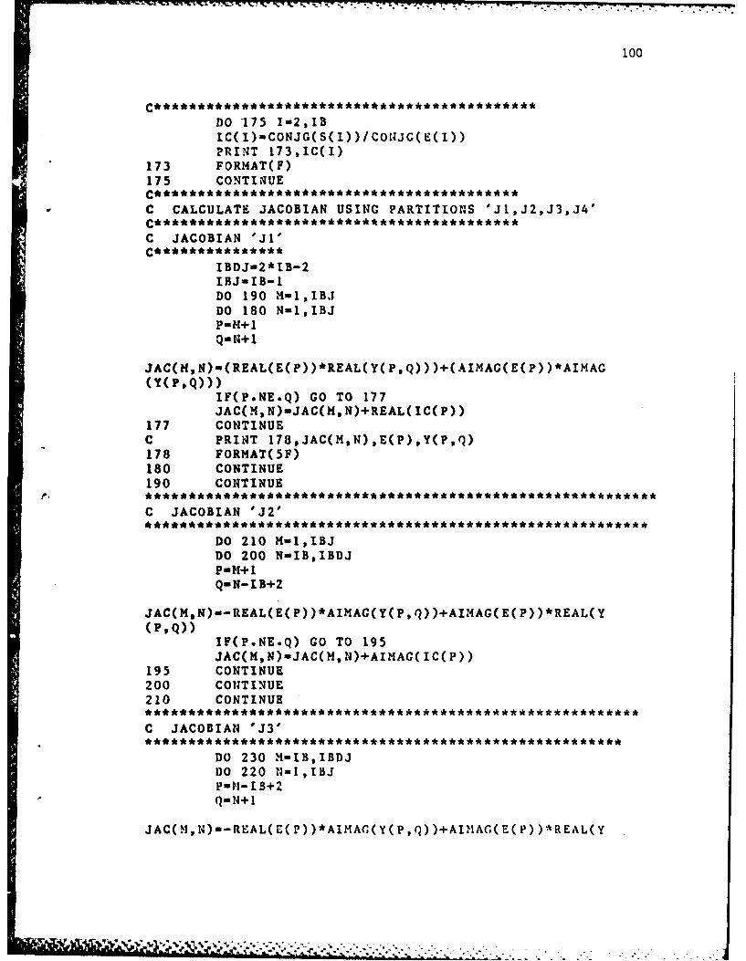
100
DO '175 I-2,13IC(I)-CONJG(S(I))/CoH4JG(E(I))PRINT 173,IC(I)
173 FORI4AT(F)175 CONTINUE
C CALCULATE JACOBIAN USING PARTITIONS 'J1,J2,J3,J4'
C JACOBIAN 'Ji'
IBDJ-2*IB-2IBJ-IB-1DO 190 M-1,IBJDO 180 N-1,IBJP-H+ I
JAC(M,N)-(REAL(E(P))*REAL(Y(P,Q)))+(AIMAG(E(P))*AIMAG(Y( P,Q)))
IF(P.NE.Q) GO TO 177JAC(M,N)-JAC(M,N)+REAL( IC(P))
177 CONTINUEC PRINT 178,JAC(M,N) ,E(P) ,Y(P,Q)178 FORMAT(5F)180 CONTINUE190 CONTINUE
C JACOBIAN 'J2'
DO 210 M-1,IBJDO 200 N-IB,IBDJP- M+Q-N-IB+2
JAC(M,N)--R~EAL(E(P))*AIMAG(Y(P,Q))+AIM4AG(E(P))*REAL(Y(1% Q))
IF(P.NE.Q) GO TO 195JAC(M,N)-JAC(M,N)+AIMAG( IC(P))
195 CONTINUE200 CONTINUE210 CONTINUE
C JACOBIAN 'J3'
DO 230 M-IB,IBDJDO 220 N-1,IBJP-11-13+2
JAC( 1,1)-REAL(1(P))*AIMA(Y(P,Q))+AlI1AG(E(P))*REAL(Y

101
(PQ)IJF(P.NE.Q) GO TO 215JAC(M,N)-JAC(M,N)-AIMAG(IC(P))
215 CONTINUE220 CONTINUE230 CONTINUE
C JACOBIAN 'J4'
DO 250 M-IB,IBDJDO 240 N-IB,IBDJP-M-IB+2Q-N-IB+2
JAC(M,N)--AIMAG(E(P))*AIMAG(Y(P,(Q))-REAL(E(P))*REAL(Y
(PQ))IF(P.NE.Q) GO TO 235JAC(M,N)-JAC(M, N)+REAL( IC( P))
235 CONTINUE240 CONTINUE250 CONTINUE
DO 334 X-I,IBDJC PRINT 333,(JAC(M,N),N-1,IBDJ)333. FORMAT(18F)334 CONTINUE
C COMPUTE INVERSE OF JACOBIANCALL HINV(JAC,6S3,IBDJ)
C PRINT 344,(JAC(M,N),N-1,IBDJ)344 FORMAT(1OF)345 CONTINUE
C COMPUTE DIFERENCE IN VOLTAGE USING JACOBIAN INVERSE 'JAC'
DO 346 1-2,13M-I-iPQVEC(M)-PDIFF( I)QQVEC(M)-QDIFF( I)
346 CONTINUEJ-IB-1DO 351 M-1,JEFDVD-OEFDQD-OEIDD-OE IQ V-0DO 349 1-1,3EFI)VD-EFDVD+JAC( !, N)*PQVEC( N)
349 CONTIN4UEDO 350 N- I B.18DJ
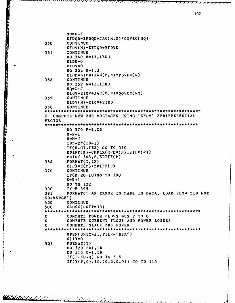
102
NQ-N-JEFDQD=EFDQD+JAC(M,N)*QQVEC(NQ)
350 CONTINUEEFDV(M)-EFDQD+EFDVD
351 CONTINUEDO 360 M-IB,IBDJEIDD-OEIQV-ODO 358 N-1,JEIDD-EIDD+JAC(M,N)*PQVEC(N)
358 CONTINUEDO 359 N-IB,IBDJNQ-N-JEQV-EIQV+JAC(M,N)*QQVEC(NQ)
359 CONTINUEEIDV(M)-EIQV+EIDD
360 CONTINUE
C COMPUTE NEW BUS VOLTAGES USING 'EFDV' EFDIFFERENTIALVECTOR
DO 370 P-2,IBM-P-iN=H+J
IBZ-2*(IB-i)IF(N.GT.IBZ) GO TO 370EDIFF(P)-CMPLX(EFDV(M),EIDV(N))PRINT 368,P,EDIFF(P)
368 FORMAT(I,2F)E(P)-E(P)+EDIFF(P)
370 CONTINUEIF(K.EQ.iO)GO TO 390K-K+1GO TO 122
390 TYPE 395395 FORMAT(' AN ERROR IS MADE IN DATA, LOAD FLOW DID NOTCONVERGE')400 CONTINUE500 CLOSE(UNIT=30)* ********** ******* ******* ** *** ****** ******* **** * *** *****
C COMPUTE POWER FLOWS BUS P TO QC COMPUTE CURRENT FLOWS AND POWER LOSSESC COMPUTE SLACK BUS POWER
******************** *** * ****** *** **** *** ** **** *
OPEN(UNIT-31,FILE-'DSK')
503 FORMAT(I)DO 520 P-=,IBDO 515 Q-,IBIF(P.EQ.Q) GO TO 515IF(Y(P,Q).EQ.(O.0,0.O)) GO TO 515
' } + a.. + + ' , "" " - + . . . - " " . - " . "" - ' -
X - * .- . .
103
Pp-P
C IF YOU ARE NOT NEGLF.CT S1UNT ADMITT REMOVE THlE NEXTC
PFLOuCONJG(E(P))*((E(P)-E(Q))*Y1(P,Q))C 1+(CONJG(E(P) )*E(P)*YS( PQ))
PFL01wCONJG(E(Q))*((E(Q)-E(P))*Y1(P,Q))C 1+(CONJG(E(Q))*E(Q)*YS(PsQ))
CRFLO(P,Q)-PFLO/CONJC(E(P))PLOS-PFLO+PFLOI
C TAKE THE CONJUGATE OF THE POWER FLOWS FOR FORMATP-J Q
PLOS-CONJG( PLOS)PFLO-CONJG( PFLO)IF(P.NE.1) GO TO 505S(1 )-PFLO+S( 1)
505 WRITE(31,509)P,Q,PFLO,CRFLO(P,Q),PLOSWRITE(31 ,510)PP,E(PP)
509 FORMAT(6X,'POWER FLOWBUS' .12, 'TO' ,12,' IS' ,2F,2X, 'CURRENT
IFLOW IS',2F,'POWER LOSS IS',2F)510 FORMAT(5X,'BUS',12,'VOLTAGE IS',2F)515 CONTINUE520 CO!lT1NUE
WRITE(31,54U) S(1)540 FORMAT(6X,'POWER AT SLACK BUS I IS',2F)
DO 550 Mt-1,IBDO 545 1-1,13IF(CABS(CRFLOOI,N)).GT.O.OOOOOI)
WRITE(33, 543)M,N,ICRFLO(M, N)
543 FORI4AT(21,2F)545 CONTINUE550 CONTINUE
WRITE(33,555)555 FORMAT(' 0 0 0.0 0.0')
CLOSE(UNIT-33)DO 600 M-1,IBDO 580 N-1,IBS(2)-E(M)*CONJG(CRFLO(M, N))PFAD-CABS( S( 2))IF(PFAD.EQ.0) GO TO 530PFAC--(REAL(S(2)) )/(PFAD)WRITE( 31, 570)?1,1N, PFAC
570 FORMAT(4X,'POWER FACT0IZ BUS' ,13,'TO' ,13,'IS' ,F)530 CONTINUE600 CONTINUE
CLOSE(UNIT-3 I)
104
STOPEND
C TITLE:?1.INV;SUBROUTI:IE TO INVERT A REAL SQUARE MATRIXSUBROUTIN4E 1INV(A,MDIM,N)DIMENSION A(MDIM,N)INTEGER L(100),M(100)
CC CONVERTED FROM SS? ROUTNE IIINVC
DO 80 K-1,NL(K)-KM( K)-KBIGA-A( K,K)DO 20 J-K,NDO 20 I-K,N
10 IF(ABS(.BIGA)-ABS(A(I,J))) 15,20,2015 BIGA-A(I,J)
L(K)-IM(K)-J
20 CONTINUEJ-L(K)IF(J-K) 35,35,25
25 DO 30 1-1,NHOLD--A(K,I)
* A(K, I)-A(J,I1)30 A(J,I)-HOLD35 t-M(K)
IF(I-K) 45,45,38
38 LO 40 J-1,NHOLD--A(J,K)A(J,K)-A(J,I)
40 A(J,I)-HOLD45 DO 55 1-1,N
IF(I-K) 50,55,5050 A(I,K)-A(IK)/(-BIGA)55 CONTINUE
DO 65 I-1,NHOLD-A( I,K)DO 65 J-1,11IF(I-K) 60,65,60
60 I(-!)62,65,6262 A(I,J)-P.0LD*A(K,J)+A( I,J)65 CONTINUE
DO 75 J-1,NIF(J-K) 70,75,70
70 A(K,J)-A(K,J)/BIGA75 CONTINUE
A(K, K)-(l1.0000000)/BIGAn0 CONTI4lUE
K-N100 K-K-I
105
IF(K) 150,150,105105 1-'L(K)
IF(I-K) 120,120,103108 DO 110 J-1,fl
IIOLD-A( J,K)A( J,K)--A(J, I)
110 A(J,I)-IiOLD120 J-M(K)
IF(J-K) 100,100,125125 DO 130 I-1,N
HOLD-A(K, I)A(K, I)--A(J, I)
130 A(J,I)-HOLDGO TO 100
150 RETURNE ND
C TITLE:ZBUS.F4;ACCEPTS DATA FROM TEST.DAT AND DSK.XFRFROMC LOAD FLOW PROGRAM LDFLO*F4 AND FORMS ZBUS BYC ALGORITHM THIS WILL BE USED TO COMPUTE ALLFAULTC CURRENTS.LOAD FLOW COMPUTED MAXIMUM LOADCURRENTS.
C READ DATA FROM TEST.DAT
DIMENSIONZD(300,3),ZM(300,2),RID(30,30,3),ZG(30),ZN(30),
1ID(200),RI(30),ZB(30,30),Z"B0(30,30),ZMU(5,5),IDD(5),ZL(30),
2ZBR(30),ZGO(30) ,ZLO(30),EB(30)COMPLEX ZD,ZM,ZG,T1,ZN,ZN1 ,ZNI,ZNJ,ZG1,ZO,1ZB, ZBO ,ZMU, ZBB, ZL, ZLL, ZBR, ZGO, ZLO, ZLLO, EBNNB-1EQUIVALENCE( ZBR, ZLO ,EB)OPEN(UNIT-31,FILE-'TEST.DAT')
C 0PEN(UNIT-32,FILE..'DSK.XFR')READ(31, 1O)IB,EBL
10 FORMAT(I,F)20 READ( 31, 30)IB, I, J, JJ,TI, ZG , ZNI, ZNJ30 FORMAT(41,8F)
IF(NB.EQ.O) GO TO 40DN-NB
'"D(NN, 2)-TiZD(WN11, 3)mZC1+3*ZN,( I)Z:Z(I )-ZNI
ZN(J)-ZNJRID(I,J,JJ)-HA4IF(NB.NE.O)CO TO 20
40 DO 45 I-1,IBC READ(32,43)Tl43 FORHAT(2F)45 CONTINUE
DO 48 I-l,IBC READ(32,46)J,Tl46 FORMAT(1,2F)
EB(J)-TI48 CONTINUE49 READ(31,50)I,Tl,XD150 FORMAT(I1, 30
IF(1.EQ.O) GO TO 60IF(CABS(TI).EQ.O) GO TO 49
C TI-CONJG(TI)C ZG(I)-3*(CABS(EB(I))**2)/Tl
IF(XDI .NE.O)ZG(I)-CMPLX(O.O,XDl)ZGO(I)-ZG(I)IF(I.NE.fl) GO TO 49
C ENTER THE ZERO SEQ IMP BUS TO REF(GROUND)
60 TYPE 6262 FORMAT(' ENTER THE SYNC ZERO SEQUENCE IMIPEDENCE FORTHE LOADS
1AT EACH'/' BUS,3*ZN,MUST BE ADDED,IMPED IN PU..,')DO 65 1-1,18ACCEPT 64,II,TlIF(II.EQ.O)GO, TO 66ZGO(II )-Ti
64 FORMAT(I, 2F)65 CON~TINUE66 DO 68 1-1,18
IF(CABS(ZGO(1)).EQ.O)ZGO(1)-ZG(t)68 CO1ITINUE
C E14TER THE MUTUALLY COUPLED ELEMEN4TS
CLOSE( UNUT-3 1)TYPE 70
70 FORMAT(' ENTER THlE MUTUALLY COUPLED ELEMENTS IN PERUNIT'/'
I IN THE FOLLOWING FORMAT, TEST. DAT.H!AS THE ELEMENT
2 (ELEMENT )SP' TO(ELEMENT )SP(O SEQ VALUE) '75 ACCEPT 30,EL,ELL,ZO80 FORMAT(4F)
IF(EL.EQ.0.O) GO TO 100

107
ZH(II. 1)-CMPLX(EL,ELL)Z11(.II. 2)-ZOGO TO 75
C ALL ELEMENT DATA PREPARED PERFORM POSITIVE ANDNEGATIVEC SEQUENCE COMPUTATIONS TO FORM ZBUS
100 DO 500 IEL-1,NNBRA-OID(IEL)-1DO 120 1-1,30
DO 120 J-1,30DO 120 JJ-1,3IF(RID(t,J,JJ).NE.IEL) GO TO
120IF(RI(I).EQ.O)GO TO
110IF(RI(J).EQ.O)GO TO
115BRA-I .0IPP-MI4O( I, J)IQQ-MAXO( I,J)GO TO 130
110 IF(RI(J).EQ.O)GO TO115
RI( 1)-i .0IPP-JIQQ-IGO TO 130
115 RI(J)-1 .0RI(I)-1 .0IPP-MINO(1, J)IQQ-MAXO(I ,J)GO TO 130
120 CONTINUE
C BRANCH OR LIiK HAS BEEN DETERMI'IED ERA-O:3RANCH
130 DO 195 IL-1,IBZBB-CMPLX(0 .0,0 .0)
131 IF(BRA.INE.0) GO TO 136IF(IQQ.EQ.IL) GO TO 190ZBR( IL)-ZB( IPP, IL)GO TO 190
186 ZL(tL)-Z3(IPP,IL)-fZB(IQQ,IL)190 CONTINUE195 CONTINUE
ZBB-CMPLX(0 .0, 0.0)IF(BRA.NE.O) GO TO 250
108
DO 200 IL-I,IBZB( IQQ, IL)-ZBR( IL)ZB( IL, IQQ)-ZBR( IL)
200 CONTINUE240 ZB( IQQ, IQQ)-ZB( IPP, IQQ)+ZD( IEL, 2)
ZBB-CMPLX(O .0,0.0)GO TO 300
250 ZLL-ZL(IPP)-ZL(IQQ)+ZD(IEL,2)ZBB-CNPLX(O .0,0.0)DO 290 IPin1,IBDO 290 IQ-1,IB
IF(IP.GT.IQ)GO TO 290
ZB( IP,IQ)'.ZB( IP, IQ)-(ZL(IP)*ZL(IQ)
1/ZLL)IF(IP.EQ.IQ) GO TO 290ZB( IQ, IP)-ZB( IP, IQ)
290 CONTINUE300 DO 350 1-1,5
DO 350 J-1,5ZHU(I,J)-CMPLX(0.O,0.0)IDD(I)-0
350 CONTINUEDO 400 1-1,IBDO 400 J-1,IB
PRINT 380,I,J,ZB(I,J)380 FORMAT( 21,2F)400 CONTINUE
NNB-1500 CONTINUE
C ZBUS iOS/NEG IS FORMED
DO 505 I-1,NNID(I)-0
505 CONTINUEDO 510 I-1,IB
RI( I)-0.O510 CONTINUE
DO 1000 IEL-1,NNBRA-0ID( IEL)-lN NB-IDO 620 1-1,30
DO 620 J-1,30DO 620 JJ-1,3IF(RID(I,-J,JJ).NE-IEL) GO TO
620IF(RI(I) .E' .O)GO TO
610

109
IF(RI(J).EQ.0) GO TO615
BRA- I .0I PP-mIINo( I,* J)
* IOQQ-MAX0(1, J)GO TO 625
610 IF(RI(J).EQ.O) GO TO* 615
RI(I)-1 .0IPP-JI QQ- IGO TO 625
615 RI(I)-1 .0RI(J)-1 .0'PP-IIQQ-JGO TO 625
620 CONTINUE
C SEARCH FOR MUTUAL COUPLING IN ZERO SEQUENCE
625 IDD(l)-IELDO 650 I-1,NN
DM -IEL
IF(AIMAG(ZM(l,l)).EQ.DM)MUT-1IF(MUT.NE.1)GO TO 650MUT-0II1-IFIX(REAL(Z19,1)))112-IFIX(AIMAG(ZM(IslI)))IF(ID(III).EQ.O)GO TO 650IF(ID(112).EQ.O)GO TO 650IF(II1.EQ.IEL)GO TO 630113-111111-112112-113
630 IDD( 1)-IIl'NNB-NNB+1IDD( NNB)-I 12DM-112DO 645 Jl-1,NN
IF(REAL(ZM(Jl,1)).EQ.DM)MUT-1
* I?(AIMAG(ZkM(J1,l)).EQ.DH)MUT-
IF(KUT.NE.1) GO TO 645MUT-0
11121lFlX(AlIMAG(ZX-(Jl,l)))IF(If(II1I).EQ .O)GO TO 645
110
IF(ID(II12).EQ.Q)GO TO 645IF(1II1.EQ.D!-) GO TO 6431113-11111111-11121112-1111
643 IF(II12.EQ.II1) GO TO 645NNB-NNB+lIDD(NNB)-1112
645 CONTINUE650 CONTINUE
DO 660 I-1,NNBZMU(I,I)-ZD(IDD(I)s3)DO 660 J-1,NNB
DDI-IDD(I)DD2-IDD(J)DO 660 KK-1,NN
IF(ZM(KK,1) .EQ.CMPLX(DDI,DD2))
1MUT-1
IF(ZM(KK, 1).EQ.CMPLX(DD2,DDI))HUT-i
IF(MUT.NE.1)GO TO 660MUT-0ZMU(1, J)-Z.I( KK, 2)ZMU( J, I)-ZM(KK, 2)
660 CONTINUE
C ZHU IS FORMED
DO 665 I-1,NI4BDO 665 J-1,NNBPRINT 663,I,J,ZHU(I,J)
663 FORHAT(21,2F)665 CONTINUE
CALL CMXINV(ZMU,5,NNB)
DO 663 I-1,NNBPRINT 667,(ZMU(I,J) ,J-1 ,NNB)
667 FORMAT(1OF)668 CON~TIN4UE
DO 695 IL-1,IBIF(NNB.EQ.l) GO TO 681ZBB-CMPLX(0.0, 0. 0)
DO 680 J4-1,NNBJ-J 4+1-
IF(I.EQ.O)) GO TO 63(0DO 670 11-1,30
.... .* ... -. ....

DO 670 12-1,30DO 670
13-1,3
I1?(RIn(11,.12,13
1).U;E.I)GO TO 670
'P-Il
IQ-12ZBB-(ZHU(1,J)/ZMU(1,1))*(ZBO(IP,IL)-ZB(IQ,IL))+ZBB
670 CONTINUE680 CONTINUE681 IF(BRA.NE.0) GO TO 686
IF(IQQ.EQ.IL) GO TO 690ZBR( IL)-ZBO(IPP, IL)+ZBBGO TO 690
686 ZL(IL)-ZBB+ZBO(IPP,IL)-ZBO(IQQ,IL)690 CONTINUE695 CONTINUE
ZBB-CMPLX(O .0,0.0)IF(BRA.NE.O) GO TO 750DO 700 IL-1,IB
ZBO(IQQ, IL)-ZBR( IL)ZBO(IL, IQQ)mZBR( IL)
700 CONTINUEIF(NNB.EQ.1) GO TO 740
* DO 730 J-2,NNBI-IDD(J)DO 720 11-1,30
DO 720 12-1,30DO 720 13-1,3
IF(RID(11,12,13).NE.I) GO TO 720IP-IlIQinI2
720 CONTINUE
ZBB-(ZMU(1,J)*(ZBO(IP,IQQ)-ZBO(IQ,IQQ
IZI4U(1, 1) )+ZBB730 CONTINUE740. ZBO(IQQ,IQQ)-ZBO(IPP,IQQ)+ZBB+1.0/ZM. U(1,1)
ZBB-CMPLX(0 .0, 0.0)GO TO 800
750 IF(NNB.EQ.1) GO TO 781DO 780 J-2,NNB
I-IDD(J)DO 770 11-1,30
Do 770 12-1,30DO 770 13-1,3

112
IF( RID( I I112,13).N'E.I)G0 TO 770
IQ-12770 CONTINUE
ZBB-(Z14U(I,J)*(ZL(IP)-ZL( IQ) )/ZHU( 1,1) )+ZBB780 CONTINUE781 ZLL-ZL(IPP)-ZL(IQQ)+ZBB+(.0/ZMU(I1))
ZBB-CMPLX(0.0 .0.0)DO 790 IP-1,IBDO 790 IQ-1,IB
IF(IP.GT.IQ)GO TO 790
Z"BO(IPIQ)-ZBO(IP, IQ)-(ZL(IP)*ZL(IQ)
I /ZLL)IF(IP.EQ.IQ) GO TO 790
790 ONTNUEZBO(IQ, IP)-ZBO(IP, IQ)
800 DO 850 1-1,5DO 850 J-1,5
ZMU( I, J)-CMPLX(O .0,0.0)IDD( I)-0
850 CON~TINUEDO 900 1-1,IBDO 900 J-1,IB
PRINT 880.I,J,ZBO(I,J)330 FORIMAT(21, 2F)900 CONTINUE
NNB-11000 CONTINUE
C ZBUS ZERO IS FORMED
OPEN(UNIT-33,FILE-'ZBUS.FOR')Do 1010 I-1,IB1)0 1010 J-1,IBWRITE(33,1005)I,J,ZBO(I,J),ZB(I,j),ZB(I,J)
1005 FORHAT(2I,6F)PRINT 1007
1007 FORMAT(3X,'BUS TO BUS ',3X,'ZERO SEQ ',5X,'POSSEQ')
PRINT 1008,I,J,ZBO(I,J),ZB(I,J)1008 FORHAT(26,4F)1010 CONTINUE
CLOSE(UNIT-32)
C NO0W TO ADD ALL LOADS. ALL LOADS WILL BE LINKS WITH
-- ~a -- d
113
110C MUTUAL COUPLING.
DO 1200 I-1,IBIF(CABS(ZG(I)).EQ.O)GO TO 1200DO 1100 IL-1,IB
ZL( IL)--ZB(I, IL)ZLO(IL)--ZBO(l, IL)
1100 CONTINUEZLL--ZL(I )+ZG( I)ZLLO--ZLO( I)+ZGO( I)DO 1150 J-1,IB
DO 1150 K-1,IBIF(J.GT.K)GO TO 1150
ZB(J,K)usZB(JK)-ZL(J)*ZL(K)/ZLL
ZB(K,J)-ZB(J,K)
ZBO(J,K)-ZBO(J, K)-ZLO(J)*ZLO(K) IZLLO
ZBO(K,J)-ZBO(J,K)1150 CONTIN4UE1200 CONTINUE
OPEN(UNIT-34,FILE-'ZBUS.DAT')DO 1300 I-1,IB
DO 1300 J-1,IB* WRITE(34,1250)I,J,ZB(I,J),ZBO(I,J)
1250 FORMAT(21,4F)1300 CONTINUE
CLOSE( UNIT-34)CLOSE(UNIT-33)OPEN(UNIT-36, FILE-'MUT. CO')DO 1400 I-1,NN
ELI-REAL(ZM(I, 1))IF(ELI.EQ.O.0)GO TO 1322EL2-AIMAG(ZM(I, 1))IELI-IFIX(EL1)IEL2-IFIX(EL2)DO 1320 I1-1,IBDO 1320 JI-1,IBDO 1320 K1-l,IBIF(RID(I1 ,JL,KI) .EQ.ELI)G0 TO 1310IF(RID(I11,Jl,Kl) .EQ.EL2)GO TO 1315
* GO TO 13201310 1311-Il
IBIJ-J 1GO TO 1320
1315 IBJI-11IBJJ-J I
1320 CONTINUE
114
1322 IF(.ELI.EQ.O)GO TO 1400
1.2)1350 IFORMAT(2F,4I3,2F)1400 CONTINUE
WRITE(36, 1450)1450 FORHAT(' 0.0 0.0 0 0 0 0 0.0 0.0')
CLOSE( UK~IT-36)STOPEND
C TITLE:CMXINV;SUBROUTINE FOR INVERT COMPLEX MATRIXSUBROUTINE CMXINV(A,HDII,N)COMPLEX A(MDIM,N),BIGA,HOLDINTEGER L(100),M(100)
CC CONVERTED FROM SSP ROUTNE MINVC
DO 80 K-1,NL(K)-KM(K)-KBIGA-A( K, K)DO 20 J-K,NDO 20 I-K,N
10 IF(CABS(BIGA)-CABS(A(I,J))) 15,20,20.15 BIGA-A(I,J)
L(K)-IM(K)-J
20 CONTINUEJ-L(K)IF(J-K) 35,35,25
25 DO 30 1-1,NHOLD--A(K, I)A(K,I)-A(J,I)
30 A(J,I)-HOLD35 I-M(K)
IF(I-K) 45,45,3838 DO 40 J-1,N
IIOLD--A( J,K)A(J,K)-A(J,I)
40 A(J,I)-HOLD45 DO 55 1-1,N4
IF(I-K) 50,55,5050 A(I,K)-A(I,K)/(-BIGA)55 CONTINUE
D)0 65 I-1,N1IOLD-A( I,K)DO 65 J-1,NIF(I-K) 60,65,60
60 IF(J--K) 62,65,6262 A(I,J)mIIOLD*A(K,J)+A(1,.])
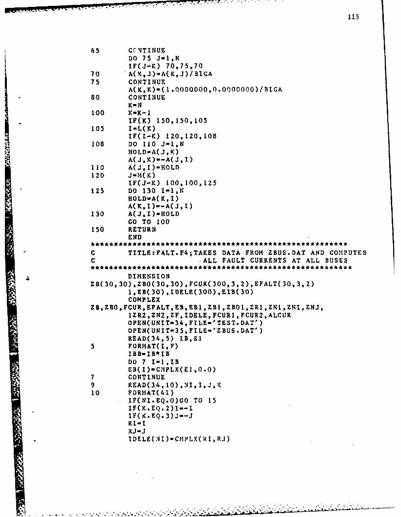
115
65 CCITINUEDO 75 J-1,NIF(J-K) 70,75,70
70 A(K,J)-A(K,J)/BIGA75 CONTINUE
A(K,K)-(1 .OOO0000,0.O000000)/BIGA80 CONTINUE
K- N100 K-K-i
IF(K) 150,150,105105 I-L(K)
IF(t-K) 120,120,108108 DO 110 J-1,N
HOLD-ACJ, K)A( J, K)'-A(J,I1)
110 A(J,I)-HOL)120 JMH(K)
IF(J-K) 100,100,125125 DO 130I-,
HOLD-A( K, I)A(K,tI)--A(J, 1)
130 A(J,I)-E[OLDGO TO 100
150 RETURNEND
C TITLE:FALT.F4;TAKES DATA FROM ZBUS.DAT AND COMPUTESC 'ALL FAULT CURRENTS AT ALL BUSES
DIMENSION* ZB(30, 30),ZBO(30,30) ,FCUR(300,3,2),EFALT(30,3,2)
* 1,EB(30) ,IDELE(300),EIB(3O)COMPLEX
ZS,T.O,FCUR,EFALT,EB,EB1,ZB1,ZBOI,ZR1,ZNIZNI,ZNJ,IZR2,ZN2,ZF, IDELE, FCUR1 ,FCUR2,ALCIJROPEN( UNIT-34, FILE-' TEST. DAT' )OPEN(UNIT-35,FILE-'ZBUS.DAT')READ(34,5) IB,E1
5 FORHAT(I,F)IBH-IB*IBDO 7 I-1,IB
*7 CONTINUE9 READ(34, 10) ,NI, I,J,K10 FORMAT(41)
IF(NI.EQ.0)GO TO 15IF(K.EO. 2)1--lIF( K.EQ. 3)J--J
RJ -JlDELEC NI)-CMPLX( RI, RJ)
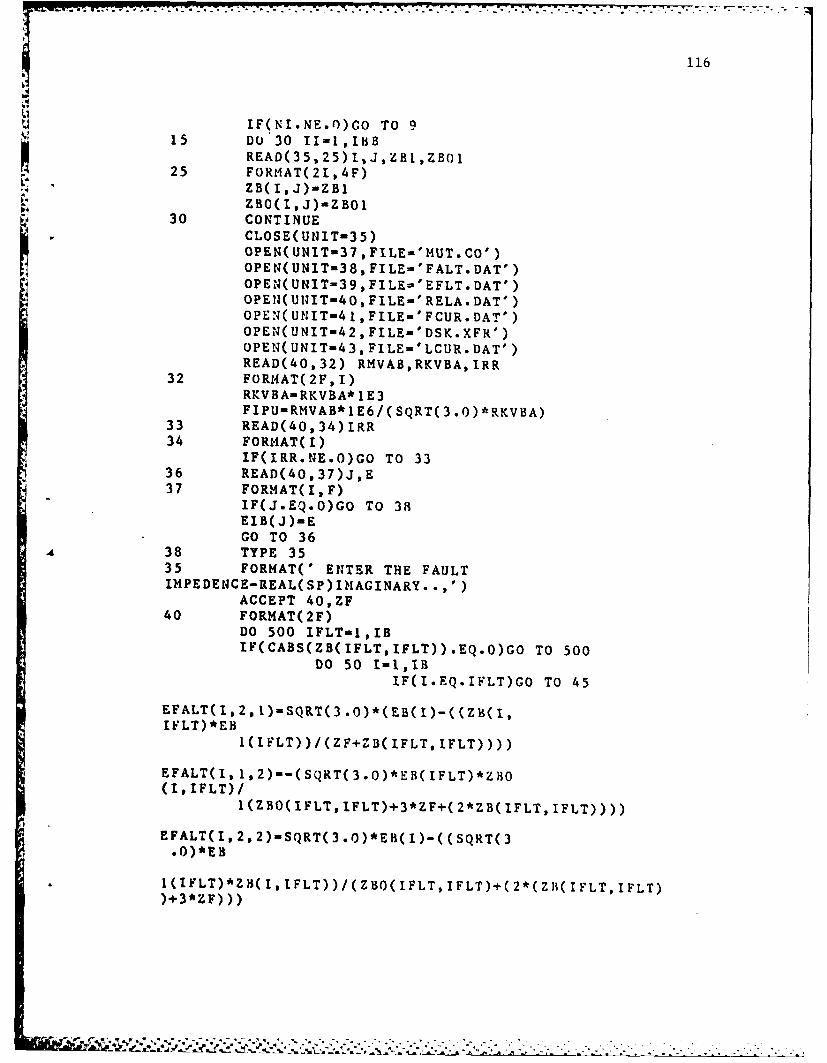
116
IF(NI.NE.O)CO TO 9
15 DO'30 II-1,IBBREAD(35, 25)I1) ZBH1, Z B(
25 FOR1IAT(21,4F)ZB( I, J)-ZB1ZBO( I, J)-ZBO1
30 CONTINUECLOSE(UNIT-35)
OPEN(UNIT-37,FILE-'IIUT.CO')p NUI-3,IE'FL.A'OPEN( UNIT-38, FILE-'EFLT. DAT')
OPEN(UNIT-43, FILE-'LCUR.DAT')READ(40,32) RMVAB,RKVBA,IRR
32 FOR14AT(2F,I)RKVBA-RKVBA*l1E3FIPU-RMVAB*lE6/( SQRT(3 .0)*RKVBA)
33 READ(40,34)IRR34 FORIIAT(I)
IF(IRR.NE.O)GO TO 3336 READ(40,37)J,E37 FORMAT(IF)
IF(J.EQ.O)Go TO 38EIB( J)-EGO TO 36
438 TYPE 3535 FORMAT(' ENTER THE FAULTIMPEDENCE-REAL(SP)IMIAGINARY. .,')
ACCEPT 40,ZF40 FORMAT(2F)
DO 500 IFLT-1,IBIF(CABS(ZB(IFLT,IFLT)) .EQ.O)GO TO 500
DO 50 t-1,IBIF(I.EQ.IFLT)GO TO 45
EFALT(I.2,1)uSQRT(3.)*(EB()-((ZB(t,IILT) *EB
I(IFLT))/(ZF+I"B(IFLT,IFLT))))
EFALT(I,1,2)--(SQRT(3.0)*EB(IFLT)*ZBO(I, IFLT) /
1 (ZBO(IFLT, 1FLT),3*ZF+i( 2*ZB( IFLT, IFLT))))
EFALT(1,2,2)-SQRT(3.O)*EB(l)-((SQRT(3.0)*EB
* 1(IVLT)*ZH(I, IFLT))/(ZBO(IFLT,IFLT)+(2*(Z~i(IFLT,IFLT)

117
EFALT(I,3,2)-EFALT(I,2,2)-(SQRT(3.0)*EBI)
GO TO 5045EFALT(IFLT,2,1)-SQRT(3.0)*(ZF*EB(IFLT)/I(Z F+
IZB( IFLT, IFLT))
EFALT(IFLT,1,2)--SQRT(3.O)*EB(IFLT)*ZBO(IFLT,
IIFLT)/(ZB0(IFLT,IFLT)4+(2*ZB(IFLT,IFLT))+3*ZF)
EFALT(IFLT, 2, 2)-SQRT(3 .0)*E-B( IFLT)*(ZBO(IFLT,
IIFLT)+ZB(IFLT, IFLT)+3*ZF)/(ZBO(IFLT, IFLT)+(2*ZB(IFLTIFLT) )43*
2ZF)
EFALT(IFLT,3,2)--SQRT(3.O)*EB(IFLT)*ZB( IFLT, IFL
IT)/(ZBO(IFLT, IFLT)+(2*ZB(IFLT, IFLT))I3*ZF)50 CONTINUE
REWIND 34REWIND 37
WRITE(39,53)(IFLT, IEFALT(I, 2.1) EFALT(I, 1,2)
IEFALT(I,2,2),EFALT(I,3,2),I-1,IB)53 FORMAT(213,8F)
READ(34, 55)II,E55 FORIIAT(I,F)
DO 90 K-1,IBBREAD(34,60)NN,I,J,KK,ZRI,ZNI,ZNI,ZNJ
60 FORNAT(4I,RF)IF(NN.EQ.O)GO TO 91FCUR(NN,2,1)-(EFALT(L,2,.1)-EFALT(J,2, I))/ZR1
FCUR(NN,1,2)-(EFALT(t,1,2)-EFALT(J,1,2))/(ZNI
1(ZNI+ZNJ))FCUR(NNl,2,2)-(EFALT(1,2,2)-EFALT(J,2,2))/ZR1FCUR( NN, 3,2 )-( EFALT( 1,3,2)- EFALT( J,3,2)) /ZRI
DO 85 12-1,IBB
READ( 37, 65)RN1 *RN2, IBI 1, BIJ,IBJI, ImJJ
1 ,ZN265 FORMAT( 2 F, 41, 2F)
tNN1-lFIX(RNI)N 2-1IF I X(Ir.2
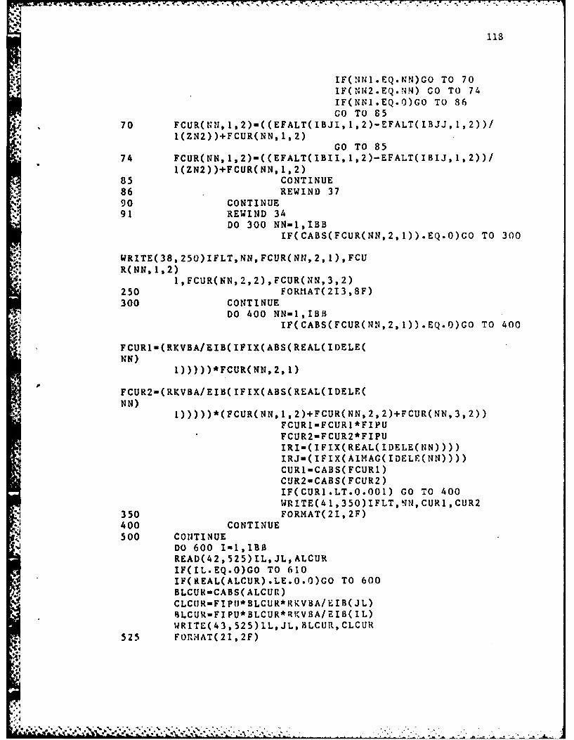
IF(NNl.EQ.NN)GOTO7IF(NN2.EQ.NN) GO TO 74IF(NNI.EQ.0)GO TO 86GO TO 85
70 FCUR(NIIf,1,2)-((EFALT(IBJI,1,2)-EFALT(IBJJ,1,2))/1(ZN2) )+FCUR(NN, 1,2)
GO TO 8574 FCUR(NN,1,2)-((EFALT(IBII,1,2)-EFALT(IBIJ,1,2))/
1(ZN2))4-FCUR(NN, 1,2)85 CONTINUE86 REWIND 3790 CONTINUE91 REWIND 34
DO 300 NN-1,IBBIF(CABS(FCUR(NN,2,1)).EQ.O)GO TO 300
WRITE( 38,*250) IFLT, MN, FCUR(MN, 2,1), FCUR(NN, 1,2)
1,FCUR(NN,2,2)9FCUR(NN,3,2)250 FORIIAT( 2 13 ,8F)300 CONTINUE
4,. DO 400 NN-1,IBBIF(CABS(FCUR(NN,2,1)).EQ.O)GO TO 400
FCUR1-(RKVBA/EIB( IFIX(ABS(REAL(IDELE(NN)
1))) ))*FCUR(NN, 2,1)
FCUR2-(RKVBA/EIB( IFIX(ABS(REAL(IDELE(NN)
1)))))*(FCUR(Nrq,1,2)+FCUR(NN,2,2)+FCUR(NN,3,2))FCURl-FCURl*FIFUFCUR2..FCUR2*FIPUIRI-( IFIX(REAL( IDELE(NN))))IRJ-(IFIX(AIMAG(IDELE(Nl))))CURl-CABS( FCUR1)CUR2-CABS( FCUR2)IF(CURI.LT.O.001) GO TO 400WRITE(4 1, 350)IFLT, NN, CURL, CUR2
350 FORMAT(2I, 2F)400 CONTINUE500 CONTINUE
Do 600 I-1,1B3READ(42,525) IL, JL, ALCURIF(IL.EQ.0)GO TO 610IF(REAL(ALCUR).LE.O.O)GO TO 600BLCUR-CABS( ALCUR)CLCRFIPUI*BLCUR*RtKVBA/EIB( JL)!LCUR-FIPU*BLCIJR*RKVBA/EIB( IL)WRITE(43,525)1L,JL,)BLCUR,CLCUR
525 FORMAT(21,2F)
4,*1
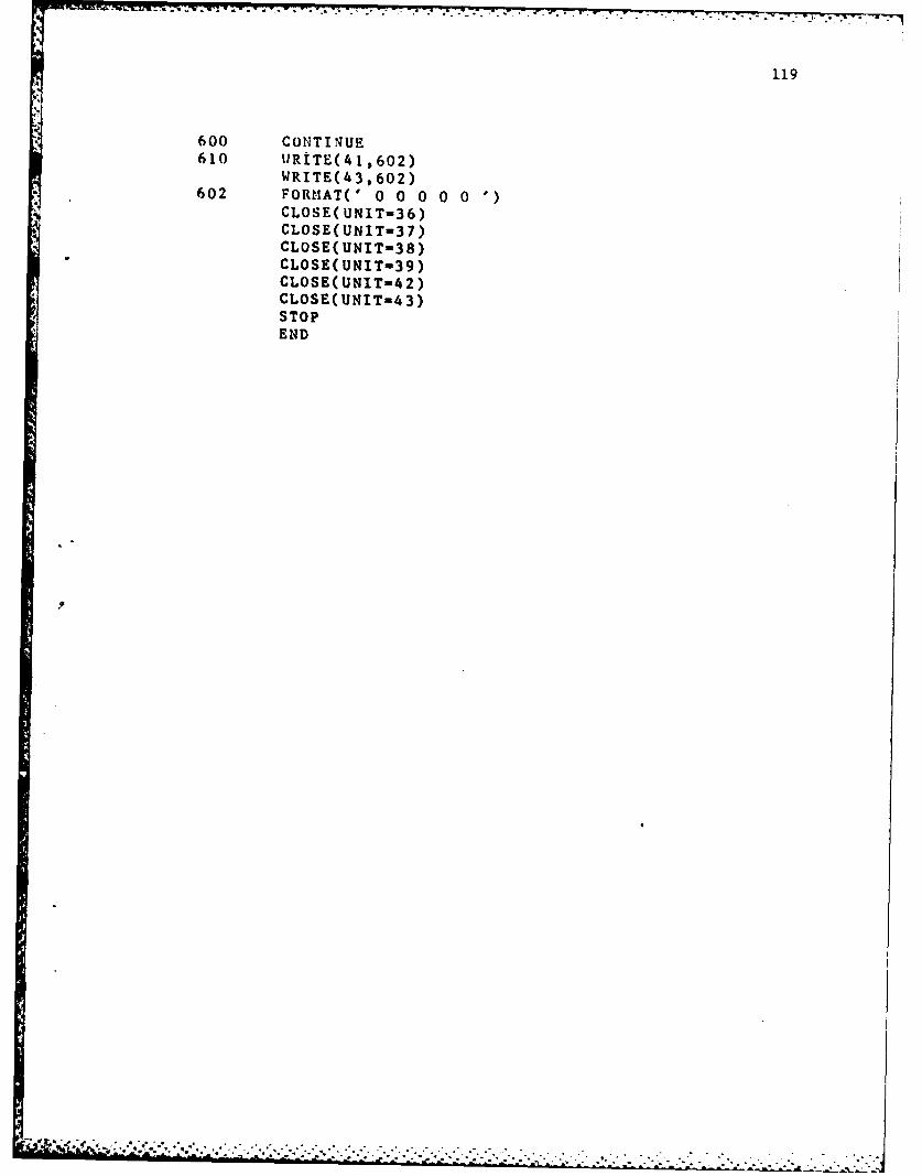
119
600 CONTINUE610 tiRiTE(41..602)
WRITE(43,602)602 FORMIAT(' 0 0 0 0 0 '
CLOSE( UNIT-36)CLOSE(UNIT-37)CLOSE( UNIT-38)CLOSE( UNIT-39)CLOSE(UNIT-42)CLOSE( UNIT-4 3)STOPEND

120
C TITLE:COORD.F4;USES DATA FROM INPUT.F4,FALT.F4 TOCOORDINATE'C THE PROTECTION DEVICES FOR THE WHOLE DISTRIBUTION
* SYSTEM.
* ******* *** ******* **** L ** ***** * ******
OPEN(UNIT-30,FILE-'LACU.DAT')* OPEN(UNIT-31 ,FILE-'LCUR.DAT')
OPEN(UNIT-32,FILE-'LCUR.DAT')OPEN(UNIT-33,FILE-'FCUR.DAT')OPEN( UNIT-34 ,FILE-'TEST. DAT')OPEN(UNIT-35,FILE-'XFOR.DAT')OPEN(UNIT-36,FILE-'DEV.DAT')
DIMENSION EB(30),CUREL(200),CURLO(30),Z( 100)1,AIDEVL(30,4) ,AIDEV( 100,7) ,XFR(200, 2) ,IID(3) ,RID( 100
2,DEV(20,0/4)COMPLEX Z,AIDEV,C1,C2,Z1,Z2,RID,CUREL,CUI ,CURLO,XFR
C READ IN LOAD AND BUS VOLTAGE DATA
READ( 30, 5)R5 FORMAT(F)
READ(34, 10)IBEl10 FORMAT(I,F)11 READ(30,12)1
* 12 FORMAT(;I)IF(I.NE.O)GO TO 11
13 READ(30,14)I,El14 FORMAT(I,F)
IF(I.EQ.0)GO TO 15EB( 1)-ElGO TO 13
15 DO 20 I-1,IB,READ(31, 16)J, CU2
16 FORMAT(I,F)IF(J.EQ.O)GO TO 21CURLO(J)-CMPLX(CU2*1 .25,0.0)
20 CONTINUE21 DO 24 1-1,20
READ(36,22)K,(DEV(I,J),J-O,4)IF(K.EQ.O)GO TO 23
22 FORMAT(I1, 5F)24 CONTINUE
C NOW TO SET ALL LOAD DEVICES
23 TYPE 25

.n..-.. . . . . . . . . . . . . . . . . . . . . . .
121
25 FORMAT(' ALL LOAD CURRENTS ARE READY,USE. DEVICENUMBER LIST,')
DO 100 I-1,IBIF(CABS(CURLO(I)).EQ.O)GO TO 100ID-I
30 TYPE 35,ID35 FORMAT(' SELECT THE DEVICE FOR THE LOAD ATBUS',13,'...'$)
ACCEPT 40,IDEVAIDEVL(ID, 1)-FLOAT(IDEV)
40 FORMAT(ICURLI-REAL( CURLO( I))CALL
SELECT(CURLI,EB( I) .AIDEVL(I, 1) AIDEVL(I, 2) ,AIDEVL(I.3)I ,AIDEVL(I,4))
Ifl0 CONTINUE
C NOW TO BEGIN COORDINATING ELEMENTS IN THEDISTRIBUTION
110 READ(34, 120)NN,I,J,K,R,X120 FORMAT(41,2F)
IF(NN.EQ.O)GO TO 130NE-NUCI- ICJ-JRID(UN)-CMPLX(CI, CJ)Z(NN)-CMPLX(R,X)GO TO 110
130 DO 140 IE-I,NEREAD(32. 135) I,J,CUI
135 FORMAT(21,2F)IF(I.EQ.O)GO TO 140IA- 0CALL SERCH(NERID,IE,I,J,IA,IID)z1-O.O*z1Z2-O .0*Z2
DO 136 IEL-1,IAZ1-1 /(Z2+Z( IID( tEL)))Z2-I/Z1
136 CONTINUEDO 138 IEL-1,IA
138 CONTINUEIF(IA.GT.1)TYPE 101,J
101 FORMAT(' CAUTION THERE IS MORE THAN ONESOURCE
lOF POWER TO THE BUS'14)140 CONTINUE
122
DO-150 I-1,NEREAD(35,145)IJ,J,TINRSHi,TIUST1,TWST2,TSI
145 FORMAT(2I,4F)IF(IJ.EQ.O)GO TO 151CALL SERCH(NE,RID,I, IJ,J,IA, lID)IA-1
147 XFR(IID(IA) , )-CMPLX(TS1 ,TINRSH)XFR(IID(IA) ,2)-CMPLX(TWST1 ,TWST2)
IA- 0150 CONTINUE
C NOW TO DETERMIINE WHAT ELEMENTS HAVE LOAD BUSSESCONNECTED
151 DO 190 I-1,NEIR-IFIX(REAL(RID(I)))IM-IFIX(AIMAG( RID( I)))IF(AIDEVL(IR,1).NE.O) GO TO 155IF(AIDEVL(IH,1).NE.O)GO TO 156GO TO 190
155 II-IFIX(REAL(RID(I)))JJmIFIX(AIMAG(RID(I)))GO TO 157
156 II-IFIX(AIMAG(RID(I)))JJ-IFIX(REAL(RID(I)))
157 CII-Ilp CJJ-JJ
AIDEV(I, 1)-CMPLX(CJJ,CII)AIDEV(I,2)-CMPLX(O.0,AIDEVL(II, 1))AIDEV( 1,4 )-CMPLX( A1DEVL(II,2), AIDEVL( 11,3))
LAIDEVL( 11,4))IF(AIDEVL(II, 1).LT.O)AIDEV(I,7)-CMPLX(0,AIDEVL(II,4
159 TYPE 158,JJ,II158 FORMAT(' SELECT DEVICE FORBUS' .13,' PROTECTING ELEMENT
IFEEDING'//' LOAD AT BUS',14,'..,'$)ACCEPT 160,IDEV
160 FORHAT(I)AIDEV1-FLOAT( IDEv)DURR-AIMAG( AIDEV( I, 4))CURR-REAL( AIDEV( 1,4))IF(AIMAG(AIDEV(I, 2)) .CT.O)CURR=1O**(DURR)CURR-REAL( CUREL( I))
CALL SELECT(CIJRR,EB(JJ) ,AIDEVI,AIDEV2,AII)EV3,CTI)CALL
SETDEV(CUREL, I,33, 11, AIDEVI,AID)EV2, AlDEV3,1AIDEV,XFR(I, I),XFR(I,2),RE,EBI(JJ),EB(II),RID,CT1,DEV
123
CTI-O.OIF(RE.NE.O)CO TO 159
190 CONTINUEIEL-O
200 NEL-NE-IELIF(REAL(AIDEV(NEL,1)).NE.O)GO TO 300
INDEX- 1I.IFIX(REAL(RID(NEL)))J-IFIX(AIMAG(RID( NEL)))IF(AIMAG(AIDEV(NEL. 2)) .NE.0)GO TO 250
205 TYPE 210,J,NELRE-0
210 FORMAT(' ENTER THE DEVICE FOR THE BUS',13,'OF
ELEMENT',*14)ACCEPT 230,IDEV
230 FORI4ATI)IF(IDEV.EQ.100)GO TO 400AIDEVP"'FLOAT( IDEV)CURRuAIMAG(CUREL(NEL))CALL SELECT(CURREB(J) ,AIDEV1,AIDEV2,AIDEV3,CTI).IF(AIDEVI.GT.34)AIDEV(NEL,5)CMPLX(0.0,.
4 14 9 7 3 )
CALL SETDEV(CURELNEL,IJ,AIDEVL ,AIDEV2,AIDEV3,IAIDEV,XFR(NEL, 1) XFR(NEL,2) ,RE,EB( I) ,EB(J) ,RID, CT1,D
EY)IF(RE.NE.O)GO TO 205
250 TYPE 210,1,NELACCEPT 230,IDEVAIDEV1""FLOAT(IDEV)RE-OCURR-REAL(CUREL(NEL))CALL SELECT(CURREB(I),AIDEVIAIDEV2,AIDEV
3 ,CT1)
IF(AIDEVI .GT. 34)AIDEV(NEL, 5)-AIDEV(NEL, 5)+CM4PLX( .414973,0.0)
CALL SETDEV(CUREL,NEL,I,J,AIDEV1,AIDEV2,AIDEV3 ,
IAIDEV,XFR(NEL,1),XFR(NEL,2),RE,EB(I),EB(J),RID,CT1,DEV)
IF(RE.NE.0)GO TO 250
300 IEL-IEL+lIF(IEL.LT-tNE) GO TO 200IF(INDEX.EQ.0)GO TO 400IEL-OINDEXO0GO TO 200
400 TYPE 410PRINT 410
410 FORMAT(' DEVICE LISTIN4G')DO 440 I-1,NETYPE 420,1,(AIDEV(t,J) ,J-1 ,7)
124
PRINT 420,1, (AIDEV(I,J),J-1 ,7)WRITE(37,420)I,(AIDEV(I,J),J-1,7)
420 FORMAT(1,14F)44q CONTINUE
WRITE(37 .442)442 FORI4AT(' 0 0.0 0.0 0.0 0.0 0.0 0.0 0.0 0.0 0.0 0.00.0
1 0.0 0.0 0.0')
2000 CLOSE(UNIT:30)CLOSE(UNIT-31)CLOSE(UNIT-33)CLOSE(UNIT-34)CLOSE( UNIT-36)CLOSE(UNIT-36)
STOPEND
C SUBROUTINE SERCH;FINDS THE ELEMENT CORRESPONDING TOTWOC BUSSES.
SUBROUTINE SERCH(NE,RID,NN, I,J, IA, lID)DIMENSION RID(I0O),IID(3)COMPLEX RID,C1,C2IA-0DO 30 IEL-1,100
CJ -JCI-'C1-CMPLX( CI, CJ)C2-CMPLX( CJCI)IF(RID(IEL).EQ.C1)GO TO 20IF(RID(IEL).EQ.C2)GO TO 20GO TO 30
20 IA-IA+1IID( IA)-IEL
30 CONTINUE31 RETURN
C SUBROUTINE REFALT;READS FCUR.DAT TO OUTPUT FAULTCURRENTSC AT THE BUSSES
SUBROUTINE REFALT(IFALT,NEL,FALTCUREL)10 READ(33,15)IEF,NN,TFAL,SFAL15 FORMAT(21,2F)

125
IF(IEF.EQ.O)CO TO 20IF(IEF.NE.IFALT)GO TO 10IF(NN.NE.NEL)GO TO 10FALTI-TFALFALT2-SFALFALT-AHINI(FALT1 ,FALT2)FLOCUR-3 .0*CURELIF(FALT.LE.FLOCUR)FALT-AMAX1(FALT1 ,FALT2)FALT-AHAX1(FALTI ,FALT2)
20 REWIND 33RETURNEND
C SUBROUTINE SETDEV; SETS THE DEVICE INSTANTANEOUSEL EM ENTC DEPENDING 01, THE FAULT CURRENT AT THAT BUSDOESC COORDINATE WITH OTHER DEVICES
SUBROUTINESETDEV(CLJREL,IEL,I,J,AIDEV1,AIDEV2,AIDEV3,AIDEV
1,XFRI,XFR2,RE,EBI,EB2,RID,CT,DEV)DIMENSION
AIDEV( 100,7) ,CUREL( 100) ,DEV(20,0/4) ,RID( 100)COMPLEX AID)EV,XFRI,XFR2,CUREL,RIDIDEVI-IFIX(AIDEV1)
30 IF(IDEVI.LT.O)CALLSETKEL(CUREL,IEL,I,J,AIDEV,AIDEVI,
1AIDEV2,AIDEV3,XFK1,XFR2,RE,EB1,EB2,RID,CT,DEV)IF(IDEV1.LT.O)GO TO 100IF(IDEV1.EQ.99)GO TO 100IF(IDEVI.LT.35.AND-lDEVI.GT.O)CALL SETFUS(CUREL(IEL1),1, J, IEL, AIDEY, IDEV1 ,AIDEV2, AIDEV3 ,XFR , XFR2 ,RE, ER1
,EB2,2DEV, RID)IF(IDEVI.GE.35.AND.IDEVI.LT.99)CALL
SETCKB(CUREL(IEL),1I,J,IEL,AIDEV,IDEVI,AIDEV2,AIDEV3,CT,EB1,E32)
100 RETURNEND
C SUBROUTINE SETFUS;COORDINATES AND SELECTS A FUSE
SUBROUTINESETFUS(CUREL,t,.i,IEL,AIDEV,IDEVl,AIDEV2,AIPEV3
1,XFRI ,XFR2,RE,EI,EB2-,nEV,Rln)DIM14E NS ION
AIDEV( 100,6), CUREL( 100), DEV( 20,0/4), RIP( 100)
- *-. . . .. . . - - 7 7. .v
126
COMPLEX AIDEV,XFR1,XFR2, CIIREL ,RliDJJ-IFIX(AIMAG(AIDEV( IEL, 2)))IF(JJ.EQ.0)CALL XFDEV( 1,J, ILL,AIDEV,COOF)IF(JJ.NE.O)CALL XFDEV(2,J, IZL,AIDEV,COOF)IF(JJ.EQ.O)CURR-AIMAG(CUREL( IEL))IF(JJ.NE.0)CURR-REAL(CUREL( IEL))IP(JJ.EQ.O.AND.COOF.LT.CURR)COOF-CURRIF(JJ.NE.O)COOF-(EB2/EB1 )*COOFIF(JJ.NE.O.AND.COOF.LT.CURR)COOF-CURRIF(IDEVI.LE. 15) CALL SFUSE(COOF,IDEVI ,OFSETOFSETI)IF(IDEVI .GT. 15) CALL SBORFU(CQoF, IDEVi ,OFSET,OFSETI)IF(JJ.EQ.O) GO TO 20Ct-ICJ -JAIDEV(IEL, 1)-CMPLX(CI,CJ)AIDEV(IEL,2)-AIDEV(IEL,2)ICPLX(FLOAT(IDEVI),O.O)AIDEV(IEL, 3)-CMPLX(OFSET,OFSET1)GO To 25
20 cl-ICJ-JAIDEV(IEL, 1)-CMPLX(CI, CJ)AIDEV(IEL,2)-CMPLX(O.O,FLOAT(IDEVI))AIDEV(IEL, 4)-CNPLX(OFSET,OFSET1)GO TO 50
25 -IF(CABS(XFRI).EQ.0)GO TO 50AX-ALOGIO((AIMAG(XFRI ))13.0)
4 IF(REAL(AIDEV(IEL,2)) .LE. 15)GO TO 35IF( OFSET.LE.AX)CUR-1 O**AXIF(OFSET.LE.AX)CALL SBORFU(CUR, IDEV,OFSET,OFSETI)GO TO 40
35 tF(OFSET.LE.AX)CUR=1O**AXIF(OFSET.LE.AX)CALL SFUSE(CUR,IDEV,OFSET,OFSETI)
40 AIDEV(IEL,2)-CHPLX(FLOAT(IDEV),AlIAG(AIDEV(IEL,2)))AIDEV(IEL, 3)-CMPLX(OFSET,OFSETI)AR-ALOG1O(REAL(XFR2))CALL FUSE(2,REAL(AIDEV(IEL,2)),AR,OFSET1,TVAL1)TVAL-1 0**TVALIIF(TVAL.GT.2.0)GO TO 43GO TO 50
43 TYPE 4545 FORMAT(' UNABLE TO PUT FUSE IN THIS LOCATIONSUBSTITUE
1ANOTHER DEVICE')RE-I .0GO To 300
50 CALL REFALT(J,IEL,FALT,CUREL(IEL))PAUSE 55IF(JJ.EQ.O)CALL
SFALTI (AIDEV, CUREL, RID, tEL, I, J,TVAL1 , DEV,
*-. ...- *.*p **. .. . . . . .. A
127
ICVAL)IF(JJ.NE.O)CALL SFALT2(AIDEViEL.,I,J,TVALI ,DEV,1FALT, CVAL)PAUSE 60ADEV-FLOAT( IDEVI)
55 CALL FUSE(1,ADEV,CVAL,OFSET,TVAL)IF(TVAL.GT.TVALI)GO TO 200ADEV- ADEV+ 1NEGDEV--IFIX( ADEV)IF(ADEV.LE.15)CALL SFUSE(COOF,NEGDEVOFSET,OFSET1)IF(ADEV.GT. 15)CALL SBORFU(COOFNEGDEV,OFSET,OFSETI)GO TO 55
200 IF(JJ.NE.0)GO TO 250AIDEV(IEL, 2)-CHPLX(O.0,ADEV)AIDEV(IEL,4)-CMPLX(OFSF.T,OFSETI)GO TO 300
250 AIDEV(IEL,2)-CMPLX(ADEV,AIMAG(AIDEV(IEL,2)))AIDEV(IEL, 3)-CMPLX(OFSET,OFSETI)
300 RETURNEND
C SUBROUTINE FUSE;COMPUTES TIME VALUE FOR A GIVEN LOADCURRENT
SUBROUTINE FUSE(ID,ADEV,CVAL,OFSET,TVAL)4 TVAL-0.0
IDEV-IFIX(ADEV)IF(IDEV.GT.15)GO TO 50X-CVAL-OF SETIF(ID*NE.1)GO TO 40TVAL-4.048O+(-36.4234*X)+(223.7526*(X**2))+(-751 .279*
(X**3))1+(1347.01*(X**4))+(-1222.67*(X**5))+(44O.813*(X**6))TVAL-TVAL-2 .0GO TO 100
40 X-CVAL-OFSETi. ITVAL-6.426+(-37.922*)Kr- ,121.9O9*(X**2))+(-213.420*(X*
1201. 77 1*(X**4 )) -. 9836*( X**5)) 13 .6046*( X**6))TVAL-TVAL-2 .0IF(X.GT.1.4)TIVALu--.95GO TO 100
50 X-CVAL-OFSETIF(ID.NE.1)GO TO 70TVAL-3.876939(-4.262768*X)+(1.21934O*(X**2))TVAL-TVAL-2.*0GO TO 100
70 X-CVAL-OFSET+.l
128
TVAL=4.614840+(-6.183224*X)+(3.23181*(X**2))+(-.6O)57136*(X** 3))
TVAL-TVAL-2 .0*100 RETURN
END
C SUBROUTINE RELAY;COMPUTES TIME VALUE FOR A GIVENCURRENTC VALUE FOR A SPECIFIC RELAY
SUBROUTINE RELAY(NDEV,CURR,TVAL,TDSET,DEV,Al1ST)DIMENSION DEV(20,0/4)TVAL=O.OX-ALOGLO( CURR)IF(X.GT.1.2)X-1.2DO0 10 1-0,4
A TVAL-TVAL+DEV(NDEV, I)*(X**I)10 CONTINUE
IF(NDEV.EQ.7)TVAL-TVAL-2 .0TVAL-TVAL+TDSETIF(CURRu.GT.AHST.AND.AMST.NE.O)TVAL--2.ORETURN
* END
C SUBROUTINE CKTBKR;COMPUTES TIME VALUE FOR A GIVENCU RRENT
4C VALUE
SUBROUTINE CKTBKR(ID,MDEV,DVAL,OFSET,TVAL, AMVAL)CVAL-DVAL-OFSETIF(ID.NE.1)GO TO 50CVAL-CVAL+. 1122IF(AMVAL. EQ.O.O)AMVAL-1OIF(CVAL.GT.AMVAL)CO TO 90TVAL-5.76908+(-10.88261*CCVAL))+(23.65419*(CVAL**2))+
(-34.79221*(CVAL**3))+(33.77472*(CVAL**4))+(-.21.14536*(CVAL**5
231778*(CVAL**6))TVAL-TVAL-2.*0CO TO 100
50 CVAL-CVAL+.2315AIIlVAL-Al4VAL+.*075IF(CVAL.GT.AtiIVAL)CO TO 95TVAL-5 .8596722+(-4.*394335*CVAL)+(.50690234*( CVAL**2)
)+( 10.4012739*(CVAL**3))+(-17.O64956*(CVAL**4))r(13.011543*(C
VAL**5))

- .7 -7-7..
129
2+(-4 .010724*(CVAL**6))TVAL-TVAL-2 .0GO TO 100II.90 TVAL--2.0GO TO 100
95 TVAL-ALOG1O(.025)*100 RETURN
END
C SUBROUTINE SETREL;COORDINATES AND SELECTS A RELAY
SUBROUTINESETREL(CUREL,IEL,I,J,AIDEV,AIDEVI,AIDEV2,AIDEV3,
1XFRI,XFR2,RE,EB1,EB2,RID,CT,DEV)DIM ENS ION
AIDEV(100,7) ,IIDD(30) ,RID(100) ,IID(3) ,CUREL( 100)1, DEV( 20, 0/4) ,FT( 30, 2)COMPLEX AIDEV,CUREL,XFRI,XFR2,RIDCOOF-O.OCURR-O.OCDUR-0.0TYPE 5
5 FORMAT(' DOES THIS RELAY HAVE AN INST. ELEMENT,IFYES 0')
* ACCEPT 7,IL7 FORMAT(I)
JJ-IFIX(AIMAG(AIDEV(IEL, 2)))MDEV-IFIX(-AIDEV1)IF(JJ.EQ.0)AIDEV(IEL,1)mCMPLX(FLOAT(I),FLOAT(J))IF(JJ.EQ.0)AIDEV(IEL, 2)=CI-IPLX(0.0, AIDEVI)IF(JJ.NE.0)AIDEV(IEL,2)-CMPLX(AIDEV1,0.0)+AIDEV(IEL,2
)FJ.QOCL FE(,,EIEOFIF(JJ.NE.)CALL XFDEV(21,J, IEL,AIDEV, GOOF)
IF(JJ.EQ.0)CURR=AIMAG(CURELCIEL))IF(JJ.NE.0)CURR-REAL(CUREL(IEL))IF(JJ.EQ.0.AND.COOF.LT.CURR)COOF-CURRIF(JJ.NE.0)COOF=(EB2/EB1)*COOFCDUR-ALOG1O( GOOF)IF(JJ.NE.0.AND. GOOF .LT.CURR)COOF-CURRIF(CDUR.GT.AIDEV2)AIDEVI=4.0
IF(CDUR.GT.AIDEV2.AND.JJ.EQ.-O)CALLI. SELECT(COOF, EB2,AIDEV1,IAIDEV2 ,AIDEV3,CT)IF(CDIR.GT.AIDEV2.AND.JJ.NE.0)CAIL
SELECT(COOF,EBI,AIDEVI,lAIDEV2 ,AIDEV3, CT)CURL-AI-AG( CUREL( IEL))
4N
. . . . . . . . . . . . . . . . . . . . .. . . - 130
IF(JJ.NE.0)AIDEV(IEL,3)UICMPLX(AII)EV2,AIDEV3)IF(JJ.EQ.O)AIDEV(IEL,4)CM.PLX(AIDEV2,AII)EV3)IF(JJ.NE.O)CLJRLU.REAL(CUREL(IEL))IF(JJ.NE.O)AIDEV(IEL,7)-CMPLX(CT,o.o)+AIDEV(lFL,
7 )IF(JJ.EQ.O)AIDEV(IEL, 7)=CMPLX(O-0, CT)IF(IL.NE.O)GO TO 100CALL REFALT(J,IEL,FALTI,CURL)IF(JJ.NE.O)GO TO 32FALT1-FALTI*(EBI /EB2)FALTI-FALTL/( 10**(REAL(AIDEV( IEL, 4))))I N-ODO 10 JI-1,30
CALL SERCH( 1,RIDIEL,J,JI, IA, LID)IF(IA.EQ.O)Go TO 10DO 8 JA-1,IA
I N-I N+ 1IIDD( IN)-I ID( IA)
8 CONTINUE10 CONTINUE
DO 30 INN-1,INID-IIDD( INN)IF(ID.EQ.IEL) GO TO 30IJ-IFIX(AIMAC(RID(ID)))CURJ-AIMAG(CUREL(ID))CALL REFALT(IJ,IDFALT,CURJ)FALT2-ALOGI O( FALT)AID-REAL(AIDEV( ID, 2))IAID-IFIX(AID)IF(IAID.GT.O)GO TO 16IF(IAID.LT.O)FALTO-FALT/( 10**(REAL(AIDEV(ID,3
NDEV--IFIX(REAL(AIDEV( ID, 2)))KFAL-IFIX( 1O*FALTO)DO 15 Kl15,KFAL,LO
RK-K*.lIF(ALOGIO(RIK).GT.1.2)GO TO 16CALL
RELAY( NDEV ,RK, TVAL , REAL( AIDEV( ID, 6))1,DEV,REAL(AIDEV(ID,S)))
CALLRELAY(MDEV, RK, TVAL2, TMSET, DEV, 0.*0)
TIMIEOm( 10**TVAL1 )+.4TI M1E RuTVAL 2TIHES-ALOG1O( TIMEO)TM SET1- T IXE S -T IXERIF(TMSETl.LE.O)GO TO 15TMSET-TMSETI+TMSET
15 CONTINUE16 IF(IAID.LT.O)GO TO 25

131
OFSET-AIMAG(AID)EV(ID, 3))FNSET-FALT2-OF SETIF(FNSET.GT.I.5)FALT2-OFSET+1.5KVAL-IFIX( 10*OFSET)KFAL-IFIX( 1O*FALT2)DO 20 K-KVALKFAL
RK-K*.lIF(AID.LT. 35) CALL FUSE(2,AID,RK,OFSET,TVAL1)IF(AID.GE. 35)CALL
CKTBKR(2,IFIX(AID),RK,OFSET,TVALL,REAL(1AIDEV(IEL, 5)))
* CUR-( 10**IRK)/( 10**(REAL(AID)EV(IEL, 3))
CALLRELAY (MDEV ,CUR, TVAL2 ,THSET, DEV,O .0 )
TIMEOU1O**TVAL1+. 4TIMER-TVAL2TIMES-ALOGI 0(TIMEO)TM SET 1-TIMES-TIMERIF(TMSETI.LE.O)GO TO 20TMSET-TMSETITMSETI
20 CONTINUE25 GO TO 3030 CONTINUE
AIDEV(IEL, 6)-CMPLX(O.O,TMSET)TMSET-O.OGO TO 45
32 AID-AIMAG(AIDEV(IEL,2))FALT2-ALOGIO( FALTI)4F(AID.GT.O)GO TO 35FALTI1FALTI*(EBI/EB2)IF(AID.LT.0)FALT-FALT1/(10**(REAL(AIDEV(IEL,4))))NDEV--IFIX(AIMAG(AIDEV(IEL, 2)))KFAL-IFIX(FALT* 10)DIF-KFAL-15
IF( ID.LE.O) ID-IDO 33 K-15,KFAL,ID
RK.K*.lRK2-RK*(EB2/EBI)*(1O**(REAL(AIDEV(IEL,4)))f10**1(REAL(AIDEV(IEL, 3))))
IF(RIK.GT.20)GO TO 34CALL
RELAY(NDEV,RK,TVALI,AIMAG(AIDEV(IEL,6)),DEV,IAIMAG(AIDEV(IEL, 5)))
CALL RELAY(MDEV,RK2,TVAL2,TMSET,DEV,O.O)TIMEOmi O**TVALI+.*4TIM ES -A LOGI10(TIME 0)TIMER-TVAL2

132
TMSETI-TIMES-TIMERIF(TMSET1.LE.O)GO TO 33TM SET-TMSET l+TMIS ET
33 CONTINUE34 AIDEV(IEL, 6)-AIDEV( tEL, 6)+CMIPLX(TM-SET,0.O)35 TMSETO.O0
IF(AID.LT.O)GO TO 45OFSET-AI1MAG(AIDEV(IEL,4))FNSET-FALT2-OFSETIF(FNSET.GT.1.5)FALT2-OFSET+1 .5KVAL-IFIX( 10*OFSET)KFAL-IFIX( 1O*FALT2)DO 40 K-KVAL,KFAL
RK=K* *IF( AID. LT. 35)CALL FUSE( 2,*AID, RK, OFSET, TVALI)IF(AID.GE.35)CALL
CKTBKR( 2, IFIX(AlD) ,RK, OFSET, TVAL , AIMAG(IAIDEV(IEL, 5)))
CUR-RK-REAL(AIDEV(IEL, 3))CURTA-1 O** CURCUR-(EB2/EBI )*(1I0**RK)CURTA-CUR/( 10**(REAL(AIDEV(IEL. 3))))IF(CURTA.LT.I.5)GO TO 40CALL RELAY(KDEV,CURTA,TVAL2,TtISET,DEV,O.0)TIME0-1O**TVALI+.4TIMERmTVAL2TIMES-ALOGi OCTIMEO)TMSETI-TIMES-TIMERIF(TMSET1.LE.O)GO TO 40TMSET-TMSET+TMSETI
40 CONTINUEAIDEV(IEL,6)-AIDEV(IEL,6)+CMPLX(TMSET,O.0)
45 TMSET-O.OIF(JJ.EQ.O.AND.FALT1 .GT.6)FALT1-6IF(IL.EQ.0.AND.JJ.EQ.0)AIDEV(IEL,5)-CMPLX(O0O,FALTI)FALTI.FALTI/(10**REAL(AIDEV(IEL, 3)))IF(FALTI.GT.6)FALTI-6IF(IL.EQ.0.AND.JJ.NE.O)AIDEV(IEL, 5)-AIDEV( tEL, 5)-iCMPL
X(FALT1,10.0)
100 RETURNEND
C SUBROUTINE SFALTI;PROVIDES THE DEVICE WITH THELONGESTC TIME AT FAULT,FIKST DEV IN ELEMENT.
SUBROUTINE SFALTI(AIDEVCURELRID, IEL,I,J,TVAL,DEV,ICYAL)
133
DIMENSION AIDEV(100,6),CUREL(100),RID(1OO),IID(3 ),
IIIDD(30) ,DEV(20,0/4)COMPLEX AIDEV,CURELIIRIDDO 10 JI-1,30
CALL SERCH(L,RIDIEL,JJI, IA,IID)IF(IA.EQ.O)GO TO 10DO 8 JA-lIA
IN-I N+ 1IIDD(IN)inIID( IA)
8 CONTINUE10 CONTINUE
Do 30 INN-1,INID"IIDD( INN)IJ-IFIX(AIMAG(RID(ID)))CURJ-AItIAG(CUREL( ID))CALL REFALT(IJ,ID,FALT,CURJ)FALT2-ALOG1 O( FALT)AID-REAL(AIDEV( ID, 2))IAID-IFIX( AID)IF(IAID.GT.32)GO TO 100FALT2-REAL(AIDEV( IEL, 4) )+. 5FALTOLO0**(FALT2)IF(IAID.LT.O)FALT-FALTO/( 1O**(REAL(AIDEV(ID,3
NDEV--IFIX(REAL(AIDEV(ID. 2)))IF(IAID.LT.O)CALL RELAY(NDEV,FALT,TVAL1,REAL
I(AIDEV(1D,6)) ,DEV,REAL(AIDEV(ID, 5)))FAL-REAL(AIDEV(IEL,4) )+. 5IF( FAL. LT. FALT2 )FALT2-FALIF( IAID.GT.0)CALL
FUSE( 2, AID, FALT2 ,AIMAG( AIDEVI(ID,3)),TVALI)
IF(TVAL.GE.TVALI)GO TO 25GO TO 30
25 IF(IAID.LT.O)CVALm-FALT2CVAL-FALTVAL-TVALl
30 CONTINUE100 RETURN
ENDII.C SUBROUTINE SFALT2;AS IN 1,COMPUTES TIMiE FOR LOAD
C ELEME14T AT FALT.
SUBROUTINE SFALT2(AIDEV,IEL,I,J,TVALI ,DEV,FALT,CVAL)DIMENSION AIDEV( 100,,) ,DEV(20,0/4)COMlPLEX AIDEV

134
FALT2-ALOGI O( FALT)AID-AIMAG(AIDEV( tEL,2))FAL-REAL(AIDEV(IEL, 3))+.5FALTuIO**(FAL)FALT3-FALT/(1O**(AIMAG(AIDEV(IEL, 3))))IF(AID.LT.O)CALL
RELAY(NDEV,FALT3,TVALIAIMAG(AIDEV(IEL1,6)),DEV,AIMAG(AIDEV(IEL,5)))IF( FAL. LT. FALT2 )FALT2-FALIF(AID.GT.O)CALL FUSE(2,AID.IFAL,AIMAG(AIDEV(IEL,4))1 ,TVALl)CVAL-FALT2RETURNEND
* SUBROUTINE XFDEV(NN,I,IEL,AIDEV,COOF)DIM4ENSION IID(30),AIDEV(100,6)COMPLEX AIDEVCOOF-O.OIX- 0
A lF(NN.NE.1)GO TO 50DO 30 IA-1,100
AID-REAL( AIDEV( IA, 1))IF(IFIX(AID).NE.I)GO TO 30Ix-tX+1IID(IX)-IA
30 CONTINUEDO 32 K-1,IX
32 CONTINUEDO 40 JA-1,IX
OFSET-AIMAG(AIDEV(IID(JA) ,3))IF(REAL(AIDEV(IID(JA),2)).LT.0)OFSET-REAL(AID
EV (1I1D(JA) ,3))
IF(REAL(AIDEV(IID(JA),*2)) .GE. 35)OFSET-REAL(AIDEV(
IIID(JA) ,5))+OFSET-.05IF(AIMAG(AIDEV(IELI 2)) .LT.O.AND.REAL(AIDEV(II
I(JA),2)).GT.0.AND.REAL(AIDEV(IID(JA),2)).LT.35)
2OFSET-OFSET+. 15[ IF(COOF.GT.OFSET)CQ TO 40COOF-OF SET
40 CONTINUEGO TO 60
50 IF(AIMAG(AIDEV(IEL, 2)) .GT.O)COOF-AIIAG(AflEV(IEL,4))IF(AIM1AG(AIDEV(IEL,2)) .LT.O)COOF-REAL(AIDEV(IEL,4))IF( AI1AG(AIDEV( [EL, 2)) .GE. 35)COOF-AIIAC( AIDEV( IIL, 5))

- ~ ~ ~ ~ ~ ~ ~ V IM *. Z.. . . . . . - .. -
135
-. 0751+COOFIF(REAL(AIDEV(IEL,2)).LT.O.AND.AIMAG(AIDEV(IEL,2)).GT
.0I.AND.AIMAG(AIDEV(IEL,2)).LT.35)COOF-COOF+.15
60 COOF-COOF+.025DOOF-1O**( COOF)COOF-DOOFRET URNEND
C SUBROUTINE SETCKB;CORDINATES AND SELECTS A THERMALMAGNETICC BREAKER.
SUBROUTINE SETCKB(CURELI,JJ,IEL,AIDEV,IDEV,OFSET1 ,OFSETI ,AMAG,EBL ,EB2)DIMENSION AIDEV(100,7),CON(5)COMPLEX AIDEV,CURELCON( 1)-2.6CON(2)-3.5CON(3)-5.OCON(4)-6.OCON(5)-7 .0J-IFIX(AIMAG(AIDEV(IEL, I)))IF(J.EQ.0)CALL XFDEV( ,.J,IEL,AIDEV,COOF)IF(J.NE.0)CALL XFDEV(2,J, IEL,AIDEV, COOF)IF(J.EQ.0)DOOF-ALOG1O(COOF)-AIMAG(AIDEV(IEL, 5))IF( J.EQ.O)COOF-1 O**DOOFIF(J.NE.0)DOOF-ALOGIO(COOF)-AIMAG(AIDEV(IEL, 5))IF( J. NE.O)COOFmlO**DOOFIF(J.EQ. O)CURR-AIMAG( CUREL)IF(J. NE.O)CURR-REAL(CUREL)IF(EB1.NE.EB2)GO TO 45IF(COOF.LT. CURR)COOF-CURRGO TO 46
45 RE2-(EB2/EBI)*COOFIF( RE2 .GE .CURR)COOF-RE2IF(RE2 .LT. CURR)COOF=CIJRR
46 CALL SBRKR(COOF,IDEV3,OFSET,OFSETI,DMMIY)IF( IDEV.LT.IDEV3)IDEV-IDEV3IF( IDEV.GE. IDEV3)IDEV-IDEV+1CI-ICJ-JJAIDEV(IF.L, 1)-CMPLX(CI,CJ)IF(J.EQ.O)AIDEV(IF.L,2)-CMPLX(O.O,FLOAT(IDEV))IF(J.NE.O)AIDEV(IEL,2)-CMLX(FLOAT(IDEV) ,O.O)4AIDEV

-~~. -7 - -7 57-.~4
136
1 (1EL, 2)IF(J.EQ.0))AIDEV(IEL,4)-CMPLX(OFSET,OFSETI)IF(J.NE.O)AIDEV(IEL,3)-CMIPLX(OFSET,OFSET1)IF(J .EQ.O)FLTu4*AIMAC(CUREL)IF( J.NE. O)FLT-.4*REAL( CUKEL)SETm1O**(OFSET-. 12)DO 50 K-1,5
TRP-CON(K) *SETIF(TRP.GT.FLT)GO TO 60
50 CONTINUE60 IF(AHAG.NE.O)AI4AG-ALOG1O(CON(K))
IF(J.EQ.O)AIDEV(IEL,5)-CMIPLX(Q.O,AMAG)IF(J.NE.O)AIDEV(IEL,5)-CMPLX(AMAG,O.O)+AIDEV(IEL,5)RETURNEND
C SUBROUTINE SELECT;SELECTS A PARTICULAR DEVICE
SUBROUTINE SELECT(CURLO,EB,ADEVLI,ADEVL2,ADEVL3,CT)IDEVLI-IFIX(ADEVLI)
54 IF(IDEVLI.EQ.O)GO TO 99IF(IDEVLI.EQ.1)GO TO 60IF(IDEVLI.EQ.2)GO TO 70IF(IDEVLI.EQ.4)GO TO 80IF(IDEVLI.GT.4)GO TO 53GO TO 58
53 TYPE 5555 FORMAT(' NO SUCH DEVICE OR DEVICE ERROR, RE-ENTER
1 DEVICE NR 1-4..,'$)ACCEPT 56, IDEVLI
56 FORMAT(I)GO TO 54
58 IF(EB.GT.600.O) GO TO 53CALL SBRKR(CURLO,IDEVLI ,ADEVL2,ADEVL3,ADEVL4)ADEVLI-FLOAT(IDEVLI)CT-ADEVL4GO TO 100
60 CALL SFUSE(CURLO,IDEVL1,ADEVL2,ADEVL3)ADEVLL-FLOAT( IDEVLI)GO TO 100
70 IF(EB.LT.600)GO TO 53CALL SBORFU( CURLO, IDEVL , ADEVL2 ,ADEVL3)ADEVL1-FLOAT( IDEVLI)GO TO 100
s0 CALL SRELA(CURLO,IDEVL1,NTAP,NCT,PKUP,CT)It ADEVL1-IDEVLI
ADE V L-P KU PADEVL3-NCT*1I0O+NTAP

137
GO TO 10099 ADEVLI-99
ADEVL2-CURLOADF.VL3-CURLO
100 CONTINUERET UR NEND
C SUBROUTINE SFUSE;USED TO SELECT A CURRENT LIMITINGFUSEC THIS MAY BE EITHER HIGH OR LOW VOLTAGE
SUBROUTINE SFtSE(CURLO,NDEV,OFSET,OFSET1)IF(NDEV.LT.O)GO TO 10DEV--11. 1522 1+( 23. 865*ALOGIO( CURLO) )-( 16. 487*( ALOGIO(
CURLO1)**2))+(2.9288*(ALOGIO(CURLO)**3))+(3.19672*(ALOG10(
CU2RLO)**4))-(1.48877*(ALOGIO(CURLO)**5))+(.177643l*(AL
OG310(CURLO)**6))NDEV-IFIX(DEV)+1IF(NDEV.GT. 15)NDEVm1 5
10 DEV-ABS(FLOAT(NDEV))OFSET-. 953 2-( .04643 3*DEV) .117 88 5*( DEV**2) )+C-. 02935
2*(DEV1**3) )+(.003 37*( DEV**4 ))+(-.000184 7*( DEV**5)) 00000O
39*(2DEV**6))OFSETI-OFSET+. IIF(NDEV.LT.-15)NDEV--1 5IF(NDEV.GT. 15)NDEV-15RET UR NEND
C SUBROUTINE SBORFU;USED TO SELECT A BORIC ACID HIGHVOLTAGEC FUSE
SUBROUTINE SBOKFU(CURLO,NDEV,OFSLT,OFSET1)ALOGC-ALOG IO( CURLO)IF(NDEV.LT.O)GO TO 10DEV-88.1643+(-215.2235*(ALOGC))+(188.22 5*(AL0GC**2))+
(-69. 13463*(ALOGC**3))+(7.4695*(ALOGC**4))+(1 .65257*(ALOGC
2(-.347786*(ALOGC**6))NDEV-IFIX(DEV)+lIF(NDEV.GT. 19)NDEV-19.
-~~~~~~~~ It 7~w~ 7.. . . . . . - 7.-
13S
10 DEV-ABS(FLOAT(NDEV))IF(NDEV.LT.O)DEV-DEV-1 5
4 OFSET-1.366111+.1134579*DEV+(-.O012654*(DEV**2))+(.0O00213*
1 (DEV**3))OFSETI-OFSET+. IIF(NDEV.LT.-19)NDEV--19IF(NDEV.GT. 19)I4DEV-19IF(NDEV.LT.0)NDEV--NDEV+1 5IF(NDEV.GT.0)IIDEV-NDEV+1 5RETURNEND
C SUBROUTINE SBRKR;USED TO SELECT A THERMAL MAGNETICBREAKER
SUBROUTINE SBRKR(CURLO,NDEV,OFSET,OFSETI,AMAG)DIMENSION CON(SCON( 1 -2 .6CON(2-3-5CON(3 -4.6CON(4)-5.6
4 . CON(5-7.0A TYPE 10
10 FORMAT(' ENTER MANUFACTURER (N.A. AT PRESENT USEFOR FUTURE
IEXPANSION)')TYPE 25
25 FORMAT(' INPUT TEMPERATURE FOR AMBIENT SHIFT,l FORLESS THAN
110 DEC C,,2 FOR 60 DEC C,'//'<CR>FOR NO SHIFT..')ACCEPT 28,IOFF
28 FORMAT(IIF(IOF.EQ. 1)OFS--. 1IF( IOF.EQ. 2)OFS-.05IF(MAN.NE.O)GO TO 80IF(CURLO.LE.600.)GO TO 30IF(CURLOoLE.800.)GO TO 50GO TO 70
30 IF(CURLO*LT.300.)!MDEV-1IF(CURLO.LT.300. )OFSET-2.47712IF( CURLO. GT. 300.0. AND. CURLO. LE. 350. )MDEV-2IF(CURLO.GT.300.0.AND.CURLO.LE.350.)OFSET-2.54407
* IF(CURLO.GT. 350.O.AND.CURLO. LE.400. )MDEV-3IF(CURLO.GT.350.0.AND.CURLO.LE.450.)OFSET-2.60206IF( CURLO.GT. 400.*0. AND. CURLO. LE.450. ) IDEV-4IF(CURLO.GT.400.0.A!ID.CURLO.LE.450.)OFSET-2.65321IF( CURLO. CT.*450.0.*AND. CURLO. LE. 500.)IIDEV-5IF(CURLO.GT.450.0.AND.CURLO.LE.500.)OFSET-2.698397
139
IF( CURLO.GT. 500. )IDEV-6IF(CURLO.GT.500.)OFSET-2.77815GO TO 80
50 IF(CURLO.LE.700.)MDEV-7IF(CURLO.LE.700.)OFSET-2.8451IF( CURLO.GT.700. )HDEV-8IF( CURLO.GT. 700. )OFSET-2 .90309GO TO 80
70 IF(CURLO.LE.1000.)MDEV-9IF(CURLO.LE. 1000.)OFSET-3.0IF(CURLO.GT. 1000. )MDEV-10IF( CURLO.CT. 1000. )OFSET-3 .3
80 NDEV-MDEV+34OFSET-OFSET+OFS+. 1122OFSET1-OFSET+. 12TYPE 90
90 FORMAT(' DOES THE DEVICE HAVE A 14AGNETICELEMENT? ( 0)YES. ')
ACCEPT 95,NOEL95 FORI4AT(I)
FCUR-4 *CURLOSETum10**(0FSET-. 12)DO 100 1-1,5
TD-SET*CON( I)IF(TD.GT.FCUR)GO TO 105
100 CONTINUE105 AIA-ALOGIO(CON(l))
IF(NOEL.NE.0)AMAG-0.0RETURNEND
C SUBROUTINE SRELA;USED TO SELECT A RELAY
SUBROUTINE SRELA(CURLO,NDEV,NTAPIINCT,PKUP,CT)TYPE 10
10 FORMAT(' SELECT MANUFACTUER (FUTURE EXPANSION)')TYPE 20
20 FORM.AT(' SELECT THE WESTINGHOUSE CO RELAY ,REFER TOTABLE' ,$)
ACCEPT 25,NUM25 FORMAT(I)
IIDE V--NUNIF( CURLO. LT. 30)CT-10IF(CURLO.GE.30.AND.CURLO.LT.120)CT-30IF(CURLO.GE. 120)CT-120IF(CT.EO. 10)NCT-1tV(CT.EQ. 30)NCT-2IF( CT. EQ. 1 20)NCT-3TAP-CUILLO/CT

140
IF(TAP.LE.l.O)GO TO 71IF(TAP.LE.i.2)GO TO 72IF(TAP.LE.i.5)GO TO 73IF(TAP.LE.2.O) GO TO 74IF(TAP.L-E.2.5)GO TO 75IF(TAP.LE.3.O)GO TO 76IF(TAP.LE.3.5)GO TO 77IF(TAP.LE.4.O)GO To 78IF(TAP.LE.5.0)GO TO 79IF(TAP.LE.6.O)GO TO 80IF(TAP.LE.7.O)GO TO 81IF(TAP.LE.8.O)GO TO 82IF(TAP.LE.iO.O)GO TO 83GO To 84
71 NTAP-iTAP-i .0GO TO 90
72 NTAP-2TAP-i .2GO TO 90
73 NTAP-3TAP-i .5GO TO 90
74 NTAP-4TAP-2.0GO TO 90
75 NTAP-5TAP-2-*5GO TO 90
76 N'TAP-6TAPm3.0GO TO 90
77 N4TAP-7TAP-3.*5GO TO 90
78 NTAP-8TAP-4.O.GO TO 90
79 NTAP-9TAP-S .0GO TO 90
80 NTAP-10TAP-6.0GO TO 90
81 NTAP-11TAP-7 .0GO TO 90
82 NTAP-12TAP-8.*0
141
GO TO 90
83 NTAP'1 3TAP 10.0GO TO 90
84 NTAP-1 4
TAP- 12.0
90 PKUP-ALOGO(TAP*CT)RETURNEND
' ' ' t~r f X, ',.i. ,, '- -,, '.' '/.;.'-'-;--":-;.''o':.--. /-;.- - .--'--.' -- . 1-

142
C TITLE:PLOTD.F4;PLOTS DEVICES FROM COORD.F4
****************************************** *
OPEN(UNIT-30,FILK-'ADEV.DAT')OPEN(UNIT-32,FILE-'DEV.DAT')OPEN(UNIT-33,FILE-'RELA.DAT')OPEN(UNIT-34,FILE-'FCUR.DAT')
EXTERNAL T25HANDIMENSION EB(30),DEV(20,O/4),AIDEV(100,7),RID(100)COMPLEX AIDEV,RIDREAD(32,3)R
3 FORMAT(F)5 READ(32,1O)I10 FORI4AT(I)
IF(I.NE.O)GO TO 515 READ(32,20)I,El20 FORMAT(I,F)
IF(I.EQ.0)GO TO 25EB( 1)-ElGO TO 15
25 DO 40 K-1,100READ(30,3O)I,(AIDEV(I,J),J-m1,7)
30 FORMIAT(1, 14F)IF(I.EQ.O)GO TO 45
40 CONTINUE45 READ(34,50)IB,El50 FORMAT(I,F)55 READ(34, 60)NN, I, J,K,R, X60 FORMAT(4I,2F)
IF(NN.EQ.O) GO TO 70NE -N NClICJ-JRID(NN)-CMPLX(CI, CJ)GO TO 55
70 DO 80 1-1,20READ(31,75)K,(DEV(I,J),J-O,4)
75 FORMAT(I,5F)IF(K.EQ.O)GO TO 400
80 CONTINUE400 TYPE 410410 FORMAT(' DEVICE LISTING')
DO 440 I-1,NE** TYPE 420,1,(AIDEV(I,J) ,J-1,7)
PRINT 420,I,(AIDEV(I,J),J-1,7)420 FORMAT(I,14F)440 CONTINUE445 TYPE 450450 FORMAT(' DEVICES HAVE BEEN SET IF YOU WANT TO PLOT

at 143
GRAPH PAPER1 ENTER(O),IF NJOT TYPEC I))
* ACCEPT 456,IP456 FORIAT(I)
IF(IP.NE.O)GO TO 480TYPE 460
460 FORMAT(' THIS WILL PLOT CURVES BASED TO THE LOWEST* VOLTAGE
1 IN THE SYSTEM.')TYPE 461
461 FORMAT(' INPUT THE CURRENT OFFSET FOR THE
GRAPHI,INTEGER..')ACCEPT 462,IAOFF
462 FORMAT(I)CALL INITTCALL LOG(IAOFF)CALL FLUSH
480 TYPE 485485 FORMAT(' INPUT ELEMENT *'
ACCEPT 490,IEL490 FORMAT(I)
I-IFIX(REAL(RID(IEL)))a J-IFIX(AIMAG(RID(IEL)))
EB1-EB( 1)DO 495 K-1,IB
EBL=AMIN1(EB1 ,EB(K))495 CONTINUE550 FAC-AL0ClO(EB(I)/EB1 )-IAOFF
FACI-ALOGIO(EB(J)/EBI )-IAOFFCUR-REAL(AIDEV(IEL. 3))CUR1-REAL(AIDEV( tEL, 4))CUR2-AIMAG(AIDEV( IEL, 3))CUR3-AIMAG(AIDEV( IEL, 4))
C NOW TO PLOT LOAD SIDE OF THE ELEMENT
CALL REFALT(J,IEL,FALT,900.O)IF(AIMAG(AIDEV(IEL,2))aGTaO) GO TO 585STL-REAL(AIDEV(IEL, 4))STP-FALT/ 1O**STLIF(AIMAG(AIDEV(IEL,5)).NE.O)STPuiAIMIAG(AIDEV(IEL,5))STI-ALOG1O(FALT)YM-(STL+FAC1 )*190+175.oXN-0.OCALL MOVEA(XM,YM)STPinIO*STPITP-IFIX( STP)IF(ITP.LT.15) VPE 575
575 FORMAT(' THE LOAD SID~E RELAY WILL. NOT BE VERY
W%-.
144
SENSITIVEI TO A FAULT')IDEV-IFIX(ABS(AIMAG(AIDEV( tEL, 2))))TYPE 570,IDEV,ITP
570 FORMAT(' IDEV,',2I)DIF-ITP-15.ID-IFIX(DIF/200.O)IF(ID.LE.O)ID-1TVAL3-1O.OTDSET-AIMAG(AIDEV(IEL, 6))DO 580 K-15,ITP,ID
RK-. 1*(FLOAT(K))CALL RELAY(IDEV,RK,TVAL,TDSET,DEV)IF( TVAL. GT. TVAL3 )TVAL-TVAL3TVAL3-TVALT-900-((TVAL+2 .0)*180)R-(ALOG10(RK)+FACI+STL)*190+175.OCALL DRAWA(T, R)
580 CONTINUEPAUSE 4IF(AIMAG(AIDEV(IEL,5)).NE.O)CALL DRAWA((900.0),R)GO TO 591
585 OFSET-CURIM=IFIX(80*OFSET)ADEV-AII4AG(AIDEV(IEL, 2))KIM-IFIX( 100*(ALOG1O(FALT)))DO 587 K-M,KIM
CVAL-K* .01IF(ADEV.LT.35)CALL FUSE(1,ADEV,CVAL,OFSET,TVAL)IF( ADEV.GE. 35)CALL
CKTBKR( 1,IFIX(ADEV) ,CVAL,OFSET,TVAL,IAIMAG(AIDEV( tEL, 5)))
TVAL-TVAL+2.*0IF(TVAL2.LT.TVAL. AND.ND.N;E. O)GO TO 539TVAL2-TVALND-iCALL
fRAWA(9OO-((TVAL)*I80),(CVAL+FAC1)*9+.75.0)587 CONTINUE589 OFSET-CUR3
CALL MOVEA(0.0,O.O)
M- IF IX (80 *OF SET)DO 588 K-I1,KIM
4 ~CVALinK* .0IF(ADEV.LT. 35)CALL FUSE(2,ADEV,CVAL,OFSET,TVAL)IF(ADEV.GE. 35)CALL
CKTBKR( 2, IFIX(ADEV) ,CVAL, OFSET, TVAL,lAIMAG(AIDEV(IEL,5)))
145
TVAL-TVAL+2.*0IF(TVAL2.LTTVAL.AIIU.ND.IIE.O)GO TO 591TVAL2-TVALN D-1CALL
DRAWA(90O-((TVAL)*18O) ,(CVALi+FAC1)*19O+175.0)588 CONTINUE
C NOW TO DRAW THE LINE SIDE
591 CALL MOVEA(O.O,O.O)AID-(REAL(AIDEV(IEL, 2)))IF(AID.GT.O)GO TO 595IDEV-IFIX(-AID)STL-REAL(AIDEV(IEL, 3))STP-FALT/ 10**STLIF(REAL(AIDEV(IEL,5)) .NE.O)STP-REAL(AIDEV(IEL, 5))YH.(STL+FAC)*190+175 .0,c11- 0. 0CALL MOVEA(XM,YM)STP-STP* 10ITP-IFIX( STP)DIF-ITP-1 5ID-IFIX(DLF/200.0)IF( tD.LE.0)ID-1TVAL3-1O.0TDSET-REAL(AIDEV( IEL, 6))DO 590 K-15,ITP,ID
RK-K*.lCALL RELAY(IDEV,RK,TVAL,TDSET,DEV)IF( TVAL. GT. TVAL3 )TVAL-TVAL3TVAL3-TVALCALL
DRAWA(900-( (TVAL+2 .0)*130),*( (ALOGLO(RK)+STL1IFAC)* 190+ 175 .0) )
590 CONTINUEIFCREAL(AIDEV(IEL,5)).NE.O)CALL
DRAWA((900.0),((ALOG10CRK)+1STL+FAC)*190+175))
595 IF(REAL(AIDEV(IEL,2)).LT.O)G0 TO 598OFSET-CURADEV-REAL(AIDEV( IEL, 2))ND-O0M-IFIX(80*OFSET)K114-IFIX( 100*ALOC1O(FALT))DO 597 K-fl,KIH
CVALmIK* .0
IF(ADEV.LE.34)CALL FUSE(I,AD9V,CVAL,0FSET,TVAL)IF(ADEV.GE. 35)CAL.
. . . . . . . .
146
CKTBKR(I,IFIX(ADEV),CVALOFSET,TVAL,IREAL(AIDEV( LEL, 5)))
TVAL-TVAL+2 .0IF(TVAL2.LT.TVAL. AND.ND.NE.O)GO TO 601TV AL 2-TV ALND-ICALL
DRAWA(9OO-(TVAL*18O),(CVAL+FAC)*19O+175.O)597 CONTINUE601 OFSET-CUR2
CALL MOVEA(O.O,O.0)
IIIFIX(80*OFSET)DO 599 K-M,KIM
CVAL-K* .01IF(ADEV.LE.34)CALL FUSE(2,ADEV, CVAL, OFSET,ITVAL)IF(ADEV.GE.35)CALL
CKTBKR(2,IFIX(ADEV) ,CVAL,OFSET,TVAL,IREAL(AIDEV(IEL, 5)))
TVAL-TVAL+2 .0IF(TVAL2.LT.TVAL.AND.ND. NE.0)CO TO 598TVAL2-TVALND-iCALL
DRAWA(9OO-(TVAL* 180) ,( CVAL+FAC)* 190+175 .0)599 CONTINUE
*598 TYPE 600600 FORMAT(' FINISHED??)
ND- 0CALL MOVEA(090,O.O)CALL FLUSHACCEPT 610,1
610 FORMAT(I)IF(I.EQ.O)CO TO 2000GO TO 445
2000 CLOSE(UNIT-30)CLOSE(UNIT-3 1)CLOSE(UNIT-32)CLOSE( UNIT-33)CLOSE( UNIT-34)CALL FINITT(O,O)STOPEND
C SUBROUTINE REFALT;READS FCUR.DAT TO OUTPUT FAULTCURRENTSC AT THE BUSSES
SUBROUTINE REFALT(IFALT,N4EL,FAIT,CUrEl.)
147
10 READ(33,15)IEF,NN,TFAL,SFAL15 FORIIAT(21, 2F)
IF(IEF.EQ.O)GO TO 20IF(IEF.NE.IFALT)GO TO 10IF(NN.L'E.NEL)GO TO 10FALTI-TFALFALT2-SFALFALT-AMIN1(FALT , FALT2)FLOCUR-3 .O*CURELIF(FALT.LE.FLOCUR)FALT-AMAXI(FALTI,FALT2)FALT-AMAX I(FALTi *FALT2)
*20 REWIND 33RET UR NEND
C SUBROUTINE FUSE;COMPUTES TIME VALUE FOR A GIVEN LOADCURRENT
SUBROUTINE FUSE(ID,ADEV,CVAL,OFSET,TVAL)TVAL-O.OIDEV-IFIX(ADEV)IF(IDEV.CT.15)GO TO 50X-CVAL-OF SETIF(ID.NE.1)GO TO 40TVAL-4.O48O+(-36.4234*X)+(223.7526*(X**2))+(-751.279*
(X**3))1+(1347.01*(X**4))4(-1222.67*(X**5))+(440.813*(X**6))TVAL-TVAL-2 .0GO TO 100
40 X-CVAL-OFSET+.lTVAL-6.426+(-37.922*X)+(121.9O9*(X**2))+(-213.420*(X*
1201. 77 1*(X**4) )+(-96. 9836*(X*5)+( 18. 6046*( K**6) )TVAL-TVAL-2.*0IF(X.GT. 1.4)TVAL--1 .95GO TO 100
50 X-CVAL-OFSETIF(ID.NE*1)GO TO 70TVALm3.876979+(-4.262768*X)+(1.21940*(X**2))TVAL-TVAL-2 .0GO TO 100
70 X-CVAL-OFSET+. 1TVAL-4.614841+(-6.I73224*X)+(3.2318O6*(X**2))+(-.6057
1 36*(X**3))TVAL-TVAL-2.*0
100 RETURNENDI
C SUBROUTINE RELAY;COMPUTHS TIME VALUE F~OR A GIVEN4

W-NOWWt iv SWTl'll - ol7 i!mr-".... 7 . ~
148
CURRENTC VALUE FOR A SPECIFIC RELAY
SUBROUTINE RELAY(NDEV,CURR,TVAL,TDSET,DEV)DIMENSION DEV(20,0/4)TVAL-0.*0X-ALOGIO( CURR)IF(X.GT. I.2)X-1 .2DO 10 1-0,4TVAL-TVAL+DEV(NDEV, I)*(X**I)
10 CONTINUEIF(NDEV.EQ.7)TVAL-TVAL-2.0TVAL-TVAL+TDSETRETURNEND
C TITLE:LOG.LOG,HAKES LOG LOG FORM FOR GRAPH OF RELAYCURVES
C OUTLINE BORDER
C MUST USE ALOG.LOG,t@SYS:GRALIB
SUBROUTINE LOG(IAOFF)CALL ERASE
* CALL !OVEA(O.0,O.O)CALL DRAWA(0.0,750.O)CALL DRAWA(1000.O,750.0)CALL DRAWA(1000.0,O.0)CALL DRAWA(O.O,0.O)CALL MOVEA(900.0,5.O)CALL fRAWA(900.O,750.0)Do 200 N4-0,4DO 100 M-1,10DN.1O**NXmBH*DNIF(XM.GT*35000) GO TO 225~X-(ALOC1O(XM) )*18oXTT-900-XXCALL MOVEA(XTT, 175.0)CALL DRAWR(O.0,575.O)
100 CONTINUE200 CONTINZUE225 CALL MOVEA(900.0, 175.0)
CALL DRAWA(0.0, 175.0)DO 400 Hl-O,20)0 300 11-1,10DN-10**;
WPM~~~ .-w 77.7 -
149
XXa(ALOGLO(XM) )*19()XT-XX+1 75
CALL MOVEA(95.0,XT)* CALL fRAWR(805.0,..)
300 CONTINUE400 CONTINUE
DO 460 M-0,3XNul75+190*4CALL MOVEA(90O.0,X4)CALL NUMBER(1O.'12')CALL MOVER(O.O, 10.0)J-IAOFF+MCALL NUMBER(J,'11')
460 CONTINUECALL CHRROT(90)CALL MOVEA(960*O,400.O)CALL ANCIIOS( 'CURRE' ,5)CALL ANCHiOS('NT I',4)CALL ANCHOS(N AMP'95)CALL ANCIIOS('S',1)CALL IOVEA(900.090.0)CALL DRAWA(900.0,750*0)DO 500 M4-0,5XNm90O-18O*NCALL MOVEA(XN,150.O)IF(M~.EQ.O)CALL NUMBER(.0l,'F3.2')
* IF(M.EQ.1)CALL IUMBER(.1,'F2.1')IF(M.EQ.2)CALL NUMBER(1,'Il')IF(M.EQ.3)CALL NUMBER(10,'12')IF(M.EQ.4)CALL NUMBER(100,'13')IF(M.EQ.5)GO TO 510
500 CONTINUE510 CALL tOVEA(20.O.140.0)
CALL NUIBER(10009'14')CALL CHRROT(0)CALL tOVEA(200.0,755.0)CALL ANCHOS('TIME ',5)
CALL ANCHOS('IN SE',5)CALL ANCHOS('CO4DS',5)CALL MOVEA(0.O,0.O)RETURNEND
C SUBROUTINE CKTBKR;COMPUTES TIME VALUE FOR A GIVEN
CURRENTC VALUE
SUBROUTINE CKTBKR(ID,MDEV,DVALOFSET,TVAL,AMIVAL)C VAL-DVA L-OF SET
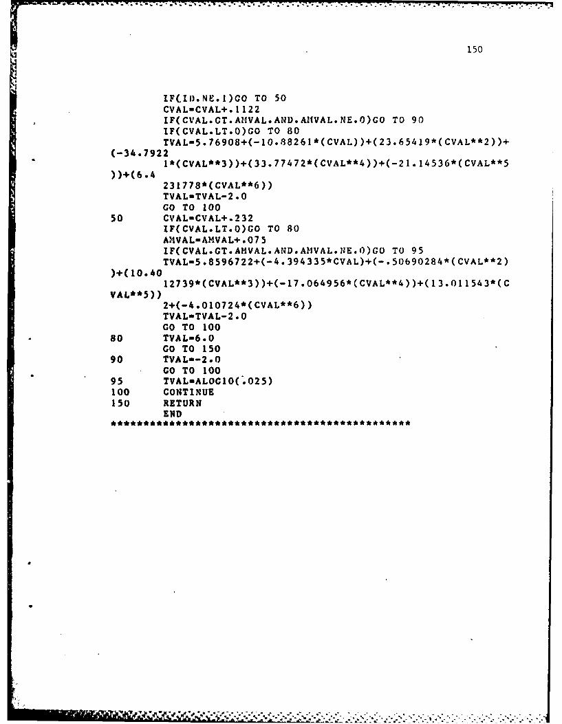
*~ * a * .* ~ **.* ~ N!- -
150
lF(.IiD.NE.l)GO TO 50CVAL-CVAL+. 1122IF(CVAL.GT.AI-IVAL.AND.AlIVAL.NE.O)GO TO 90IF(CVAL.LT.O)GO TO 80TVALn5.76908+(-l0.88261*(CVAL))+(23.65419*(CVAL**2))+
(-34.79221*(CVAL**3)).(33.77472*(CVAL**4))+(-21.14536*(CVAL**5
231778*(CVAL**6))TVAL-TVAL-2.*0GO TO 1OO
50 CVAL-CVAL+.232lF(CVAL.LT.0)GO TO 80A4VAL-AHVAL+.*075IF(CVAL.GT.AMVAL. AND.AIIVAL.N,,E.0)GO TO 95TYALuS .8596722+(-4. 394335*CVAL)+(. 50690284*(CVAL**2)
)+( 10.4012739*(CVAL**3))+(-17.064956*(CVAL**4))+(13.011543*(C
VAL**5))2+(-4.010724*(CVAL**6))TVALeTVAL-2.*0GO TO 100
s0 TVAL-6.OGO TO 150
90 TVAL--2.OGO TO 100
95 TVAL-ALOGZO(.025)100 CONTINUE150 RETURN
END
- ,. . . . . . . . . . . .. . .-7.7
151
APPENDIX C
DISK-FILE FORMATS
. .. ..* .' .~' . ~ . .:. . . .
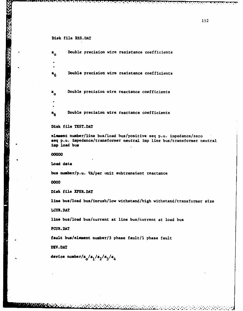
-. - t~ t -- - . 9* -- .- .. .,.......................... .. ...... -.
152
Disk file RES.DAT
a Double precision wire resistance coefficients0
a6 Double precision wire resistance coefficients
a Double precision wire reactance coefficients
a6 Double precision wire reactance coefficients
Disk file TEST.DAT
element number/line bus/load bus/positive seq p.u. impedance/zeroseq p.u. impedance/transformer neutral imp line bus/transformer neutralimp load bus
00000
Load data
bus number/p.u. VA/per unit subtransient reactance
0000
Disk file IPER.DAT
line bus/load bus/inrush/low withstand/high withstand/transformer size
LCUR. DAT
line bus/load bus/current at line bus/current at load bus
FCUR. DAT
fault bus/element number/3 phase fault/l phase fault
DEV. DAT
device number/ao/al/a2/a3/a4
; ,..--..'

153
AMY. DAT
element number/element bus numbers/device numbers/line bus elementlow pickup, high pickup/load bus element low pickup, high pickup/magnetic settings line, load/time dial setting line, load/CT ratiosline,load/
1
i-4 ' . . " " " "
" ' " ; " _f ' " ' ' ' '' '''', ' ' '

154
APPENDIX D
SAMPLE PROGRAM DATA INPUT
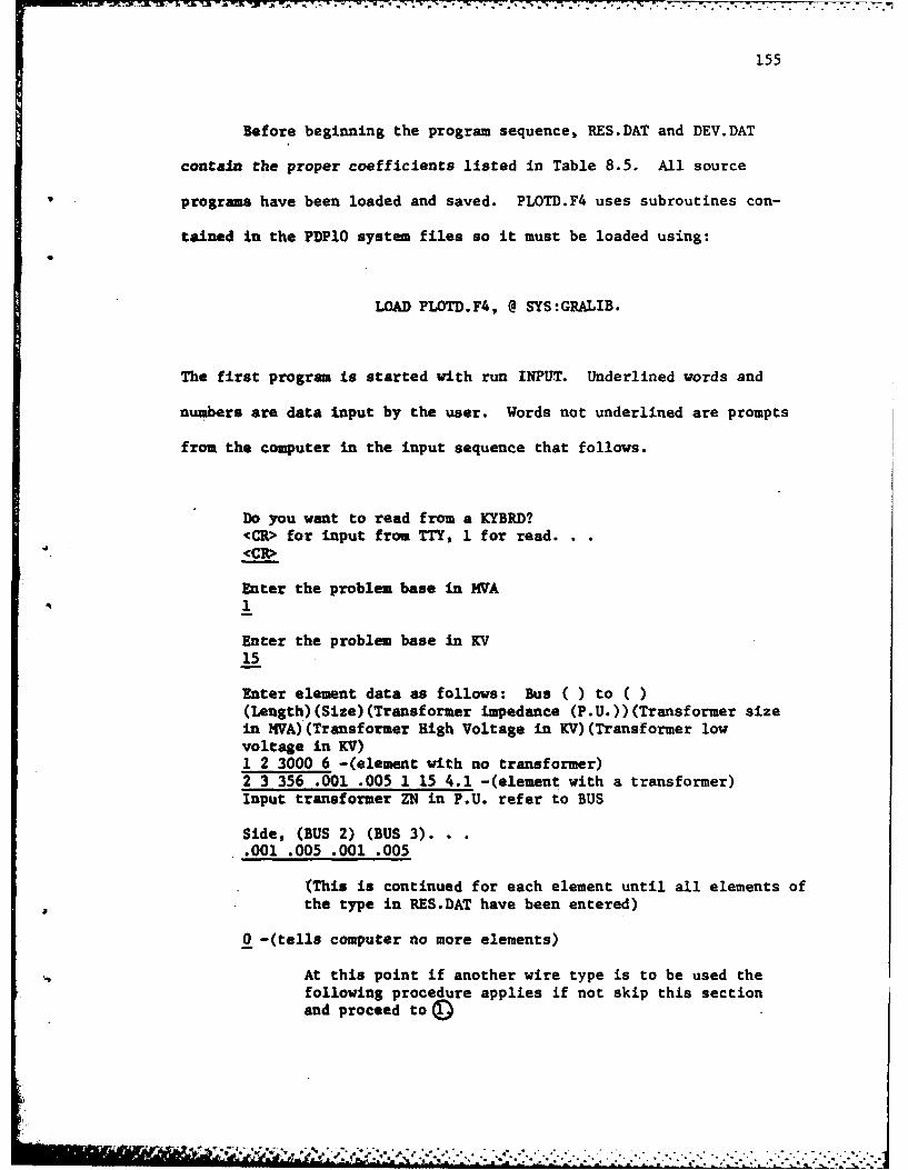
155
Before beginning the program sequence, RES.DAT and DEV.DAT
contain the proper coefficients listed in Table 8.5. All source
programs have been loaded and saved. PLOTD.F4 uses subroutines con-
tained in the PDPl0 system files so it must be loaded using:
LOAD PLOTD.F4, @ SYS:GRALIB.
The first program is started with run INPUT. Underlined words and
numbers are data input by the user. Words not underlined are prompts
from the computer in the input sequence that follows.
Do you want to read from a KYBRD?<CR> for input from TTY, 1 for read.<CR>
Enter the problem base in MVA1
Enter the problem base in KV15
Enter element data as follows: Bus ( ) to ( )(Length) (Size) (Transformer impedance (P.U.)) (Transformer sizein MVA)(Transformer High Voltage in KV)(Transformer lowvoltage in KV)1 2 3000 6 -(element with no transformer)2 3 356 .001 .005 1 15 4.1 -(element with a transformer)Input transformer ZN in P.U. refer to BUS
Side, (BUS 2) (BUS 3)..001 .005 .001 .005
(This is continued for each element until all elements ofthe type in RES.DAT have been entered)
0 -(tells computer no more elements)
At this point if another wire type is to be used thefollowing procedure applies if not skip this sectionand proceed to(D

156
Input BUSu 1 voltage. . .0Data 'is accepted and a list follows
(Here the computer types all computed information on theelements entered so that they may be checked for error.)
Now enter the load data in the following manner;. .(Bus) (Load in KVA)(Pwr Factor)...or... .(Bus) (Load in HP)(Pwr Factor)...or.....(Bus)(Load in Amps)(Pwr Factor)What method will you use?. . .VA, HP, or Amps?S -(writes element data computed to disk)End of execution(Load RES.DAT with the new wire type coefficients)RUN INPUTDo you want to read from a KYBRD?<CR> for input from a TTY, 1 for read.
Old data is entered ready for new line dataEnter element data as follows. .. (Program runs as
in the first section)
Picking up the program from completion of element data,the data entry follows.
Input Bus 1 Voltage. . .15000Input Bus 2 Voltage. . .15000Input Bus 3 Voltage. . .4100
Input'Bus 8 Voltage. . .440Data is accepted and a list follows
(Computer types computed element data).
Number of buses is 8Now enter the load data in the following manner;...(Bus)(Load in KVA)(Pwr Factor)...or... .(Bus) (Load in HP)(Pwr Factor). . .or. .. (Bus)(Load in Amps) (Pwr factor)What method will you use? KVA, HP, or Amps?HPEnter...4 800 .80What method will you use?. . .KVA, HP, or Amps?HP8 500 .90
(This is continued until all loads are entered?What method will you use?. . .KVA, HP, or Amps?
SEnd of ExecutionRUN LDFLOEnd of ExecutionRUN ZBUSEnter the zero sequence impedance for the loads at each bus.
Jk_
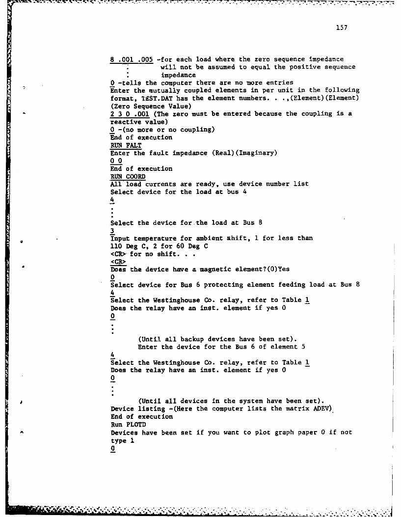
157
8 .001 .005 -for each load where the zero sequence impedance* will not be assumed to equal the positive sequence* impedance
0 -tells the computer there are no more entriesEnter the mutually coupled elements in per unit in the followingformat, I£ST.DAT has the element numbers. . .,(Element)(Element)(Zero Sequence Value)2 3 0 .001 (The zero must be entered because the coupling is areactive value)0 -(no more or no coupling)End of executionRUN FALTEnter the fault impedance (Real)(Imaginary)00End of executionRUN COORDAll load currents are ready, use device number listSelect device for the load at bus 44
Select the device for the load at Bus 83Input temperature for ambient shift, 1 for less than110 Deg C, 2 for 60 Deg C<CR> for no shift.<CR>Does the device have a magnetic element?(0)Yes0Select device for Bus 6 protecting element feeding load at Bus 84Select the Westinghouse Co. relay, refer to Table 1Does the relay have an inst. element if yes 00
(Until all backup devices have been set).Enter the device for the Bus 6 of element 5
4
Select the Westinghouse Co. relay, refer to Table 1Does the relay have an inst. element if yes 00
(Until all devices in the system have been set).Device listing -(Here the computer lists the matrix ADEV).End of executionRun PLOTDDevices have been set if you want to plot graph paper 0 if nottype 10
T 'B ,. ., .v _ ,. ./.,., ...,. ...,.,. ... :. . ,- -, ... . . . ,, ... , -
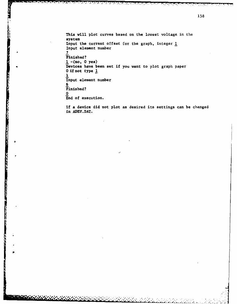
T77. -. . .
158
This will plot curves based on the lowest voltage in thesystemInput the current offset for the graph, integer 1Input element number7
Finished?1 -(no, 0 yes)Devices have been set if you want to plot graph paper0 if not type 11Input element number6Finished?0End of execution.
If a device did not plot as desired its settings can be changedin ADEV.DAT.
,.7

I L M E D
8 3