Protection for Unexpected Delta Sources · Protection for Unexpected Delta Sources Ken Behrendt...
29
Protection for Unexpected Delta Sources Ken Behrendt Schweitzer Engineering Laboratories, Inc. Presented at the 57th Annual Georgia Tech Protective Relaying Conference Atlanta, Georgia May 7–9, 2003 Originally presented at the 29th Annual Western Protective Relay Conference, October 2002
Transcript of Protection for Unexpected Delta Sources · Protection for Unexpected Delta Sources Ken Behrendt...

Protection for Unexpected Delta Sources
Ken Behrendt Schweitzer Engineering Laboratories, Inc.
Presented at the 57th Annual Georgia Tech Protective Relaying Conference
Atlanta, Georgia May 7–9, 2003
Originally presented at the 29th Annual Western Protective Relay Conference, October 2002
1
PROTECTION FOR UNEXPECTED DELTA SOURCES Ken Behrendt
Schweitzer Engineering Laboratories, Inc. New Berlin, WI USA
ABSTRACT Utilities commonly use delta-wye transformers to serve three-phase customer loads from their transmission networks and distribution feeders. With the proliferation of distributed generation installed at the customer load site, these delta-wye transformers become sources of fault current that can be difficult to detect and isolate. Under worst-case scenarios, without proper protection, the customer generation may keep the faulted utility circuit energized even after the utility source breakers have opened.
This paper discusses various techniques used to detect faults from delta sources. The paper reviews the nature of fault current contributions and voltage characteristics from ungrounded delta sources through the use of sequence component analysis. The paper also discusses the possible impact of distributed generator control systems and interconnection protection. Armed with this information, utility engineers and their customers can determine what protection and control schemes they need to ensure faults are cleared properly to avoid the hazards of uncleared faults.
INTRODUCTION Utilities use delta-wye transformers extensively in utility systems to connect transmission and subtransmission systems to distribution systems and large three-phase customer loads. This transformer configuration offers several beneficial effects, including improving load balance and blocking zero-sequence current flow, which simplifies ground fault protection.
Figure 1 shows a simplified one-line diagram representing a typical connection from a utility source substation to a customer load through a delta-wye transformer. The delta-wye transformer could be located at a utility-owned distribution substation, or the delta-wye transformer could be located at a customer-owned substation. The line could be radial, as shown in this figure, or it could be networked to another source substation with the delta-wye transformer tapped on the line between the two substations. The line may very likely supply other customer loads or utility substations. Protective relaying, appropriate to detect line faults and trip the associated line breaker, is installed at the utility source substation.
Figure 1 also shows the sequence component networks needed to analyze balanced and unbalanced fault conditions that occur on the utility line. Note that the representation for the delta-wye transformer in the zero-sequence network includes an open circuit between terminals H and L. This open circuit prevents the flow of zero-sequence current through the transformer, which is a characteristic of the delta-wye transformer.

2
The fundamental equations for deriving phase currents (IA, IB, and IC) and phase-to-neutral voltages (VA, VB, and VC) are as follows:
IA = I1 + I2 + I0 IB = a2I1 + aI2 + I0 IC = aI1 + a2I2 + I0
VA = V1 + V2 + V0 VB = a2V1 + aV2 + V0 VC = aV1 + a2V2 + V0
Where unity operator a = 1 ∠120 degrees.
Legend
Z1S: Positive-Sequence Source ImpedanceZ1L: Positive-Sequence Line ImpedanceZ1T: Positive-Sequence Transformer ImpedanceZ1Load: Positive-Sequence Load Impedance
Z2S: Negative-Sequence Source ImpedanceZ2L: Negative-Sequence Line ImpedanceZ2T: Negative-Sequence Transformer ImpedanceZ2Load: Negative-Sequence Load Impedance
Z0S: Zero-Sequence Source ImpedanceZ0L: Zero-Sequence Line ImpedanceZ0T: Zero-Sequence Transformer ImpedanceZ0Load: Zero-Sequence Load Impedance
Line
TransformerLoadUtility Source
Substation
Symmetrical Component Diagrams
E1S Positive-Sequence Network
Z1S Z1L Z1T
Z1 Load
Negative-Sequence Network
Z2S Z2L Z2T
Z2 Load
Zero-Sequence Network
Z0S Z0L
Z0T Z0 Load
S H L
S H L
S H L
S H L
Figure 1 Typical Utility Source to Customer Load Through a Delta-Wye Transformer
Figure 2, Figure 4, and Figure 6 show the simplified one-line diagrams and appropriate sequence component network connections for three-phase, phase-to-phase, and phase-to-ground faults, respectively, on the utility line. During the fault, the sequence current flowing through the load is significantly smaller than the sequence current from the utility source to the fault for two reasons. First, the fault collapses the positive-sequence voltage applied to the load, which reduces the current through the passive load impedance, and secondly, the load impedance is significantly higher than the utility source and line impedances. For all practical purposes, the load impedance is considered infinite and ignored in the fault current calculation.
To simplify the discussion, this paper ignores a fourth type of fault, the phase-to-phase-to-ground fault. This fault is a combination of phase-to-phase and phase-to-ground faults. Results from the analysis of these individual fault types can generally be extrapolated to determine the effect of a phase-to-phase-to-ground fault.
With only the utility providing a source of power to the customer load, faults on the line between the utility-source substation and the delta-wye transformer are completely isolated when the utility-source line breaker opens, as shown in Figure 3, Figure 5, and Figure 7, for each of the fault types. Symmetrical component analysis for currents and voltages on the line and at the customer load site readily shows that all currents and voltages on the isolated system are zero.
3
Line
TransformerLoadUtility Source
Substation
Symmetrical Component Diagrams
E1S
Positive-Sequence Network
Z1S Z1L Z1T
Negative-Sequence Network
Z2S Z2L Z2T
Z2 Load
Zero-Sequence Network
Z0S Z0L
Z0T Z0 Load
S H L
S H L
S H L
S H L
3φ
V1S V1H V1LI1>0 I1≈0
V2S V2H V2LI2=0 I2=0
V0S V0HI0=0
V0L
I0=0
Z1 Load
�
Line
TransformerLoadUtility Source
Substation
Symmetrical Component Diagrams
E1S
Positive-Sequence Network
Z1S Z1L Z1T
Negative-Sequence Network
Z2S Z2L Z2T
Z2 Load
Zero-Sequence Network
Z0S Z0L
Z0T Z0 Load
S H L
S H L
S H L
S H L
3φ
V1S V1H V1LI1=0 I1=0
V2S V2H V2LI2=0 I2=0
V0S V0HI0=0
V0L
I0=0
Z1 Load
�
Figure 2 Three-Phase Line Fault Figure 3 Three-Phase Line Fault With Utility
Source Breaker Open
Line
TransformerLoadUtility Source
Substation
Symmetrical Component Diagrams
E1S
Positive-Sequence Network
Z1S Z1L Z1T
Negative-Sequence Network
Z2S Z2L Z2T
Zero-Sequence Network
Z0S Z0L
Z0T Z0 Load
S H L
S H L
S H L
S H L
φ �φ
V1S V1H V1LI1>0 I1≈0
V2S V2H V2LI2>0 I2≈0
V0S V0HI0=0
V0L
I0=0
Z1 Load
�
Z2 Load
�
Line
TransformerLoadUtility Source
Substation
Symmetrical Component Diagrams
E1S
Positive-Sequence Network
Z1S Z1L Z1T
Negative-Sequence Network
Z2S Z2L Z2T
Zero-Sequence Network
Z0S Z0L
Z0T Z0 Load
S H L
S H L
S H L
S H L
φ �φ
V1S V1H V1LI1=0 I1=0
V2S V2H V2LI2=0 I2=0
V0S V0HI0=0
V0L
I0=0
Z1 Load
�
Z2 Load
�
Figure 4 Phase-to-Phase Line Fault Figure 5 Phase-to-Phase Line Fault With
Utility Source Breaker Open

4
Line
TransformerLoadUtility Source
Substation
Symmetrical Component Diagrams
E1S
Positive-Sequence Network
Z1S Z1L Z1T
Negative-Sequence Network
Z2S Z2L Z2T
Zero-Sequence Network
Z0S Z0L
Z0T
S H L
S H L
S H L
S L
φ � G
V1S V1H V1LI1>0 I1≈0
V2S V2H V2LI2>0 I2≈0
V0S V0HI0>0
V0L
I0≈0
H
Z1 Load
�
Z2 Load
�
Z0 Load
�
Line
TransformerLoadUtility Source
Substation
Symmetrical Component Diagrams
E1S
Positive-Sequence Network
Z1S Z1L Z1T
Negative-Sequence Network
Z2S Z2L Z2T
Zero-Sequence Network
Z0S Z0L
Z0T
S H L
S H L
S H L
S L
φ � G
V1S V1H V1LI1=0 I1=0
V2S V2H V2LI2=0 I2=0
V0S V0HI0=0
V0L
I0=0
H
Z1 Load
�
Z2 Load
�
Z0 Load
�
Figure 6 Phase-to-Ground Line Fault Figure 7 Phase-to-Ground Line Fault With Utility Source Breaker Open
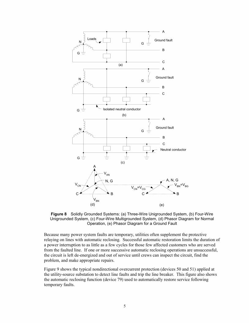
Isolation is an important concept that is used extensively on electric power systems to ensure safe and reliable operation: safe from the standpoint that protective devices automatically de-energize and isolate faulty equipment or downed conductors to protect the public and also to protect utility operating and maintenance personnel who get called upon to make repairs, reliable from the standpoint that customers expect, and regulatory bodies dictate, that electric power be delivered within prescribed voltage limits to prevent damage and maintain proper operation of customer utilization equipment. Power system faults in grounded systems cause significant voltage sags and swells that violate these prescribed limits. Isolating and de-energizing the faulty power system element restores proper power delivery to most customers and interrupts power delivery to customers on the faulty circuit. In this case, a few customers with no power is preferable to having many customers with inadequate power quality [6].
Another important issue is the relationship between power system design and operation. Equipment installed on a radial circuit with a solidly grounded wye source, as in our example system, operates at all times within the phase-to-ground voltages established during normal balanced conditions. All fault types tend to decrease the phase-to-ground and phase-to-phase voltage, but never increase the voltage. The system can use phase-to-ground connected equipment designed for the nominal phase-to-ground voltage. Phase-to-phase connected equipment can be designed for use at the nominal phase-to-phase voltage. The normal voltage triangle shown in (d) of Figure 8 defines the nominal phase-to-ground and phase-to-phase operating voltages for three- and four-wire configurations of a solidly grounded system. As shown in (a), (b), and (c) of Figure 8, loads can be connected either phase-to-phase or phase-to neutral on this type of system [1].
5
(b)
A
C B C B
A, N, GVBN=VBGVCN=VCG
VAN
N, G
VBN
VCN
(d) (e)
A
B
C
N
G
GGround fault
(a)
Loads
(c)
A
B
C
N
G
GGround fault
Neutral conductor
A
B
C
N
G
GGround fault
Isolated neutral conductor
Figure 8 Solidly Grounded Systems: (a) Three-Wire Unigrounded System, (b) Four-Wire Unigrounded System, (c) Four-Wire Multigrounded System, (d) Phasor Diagram for Normal
Operation, (e) Phasor Diagram for a Ground Fault
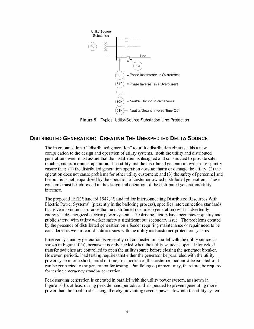
Because many power system faults are temporary, utilities often supplement the protective relaying on lines with automatic reclosing. Successful automatic restoration limits the duration of a power interruption to as little as a few cycles for those few affected customers who are served from the faulted line. If one or more successive automatic reclosing operations are unsuccessful, the circuit is left de-energized and out of service until crews can inspect the circuit, find the problem, and make appropriate repairs.
Figure 9 shows the typical nondirectional overcurrent protection (devices 50 and 51) applied at the utility-source substation to detect line faults and trip the line breaker. This figure also shows the automatic reclosing function (device 79) used to automatically restore service following temporary faults.
6
Line
Utility SourceSubstation
3
50P
51P
50N
51N
Phase Instantaneous Overcurrent
Phase Inverse Time Overcurrent
Neutral/Ground Instantaneous
Neutral/Ground Inverse Time OC
79
1
Figure 9 Typical Utility-Source Substation Line Protection
DISTRIBUTED GENERATION: CREATING THE UNEXPECTED DELTA SOURCE The interconnection of �distributed generation� to utility distribution circuits adds a new complication to the design and operation of utility systems. Both the utility and distributed generation owner must assure that the installation is designed and constructed to provide safe, reliable, and economical operation. The utility and the distributed generation owner must jointly ensure that: (1) the distributed generation operation does not harm or damage the utility; (2) the operation does not cause problems for other utility customers; and (3) the safety of personnel and the public is not jeopardized by the operation of customer-owned distributed generation. These concerns must be addressed in the design and operation of the distributed generation/utility interface.
The proposed IEEE Standard 1547, �Standard for Interconnecting Distributed Resources With Electric Power Systems� (presently in the balloting process), specifies interconnection standards that give maximum assurance that no distributed resources (generation) will inadvertently energize a de-energized electric power system. The driving factors have been power quality and public safety, with utility worker safety a significant but secondary issue. The problems created by the presence of distributed generation on a feeder requiring maintenance or repair need to be considered as well as coordination issues with the utility and customer protection systems.
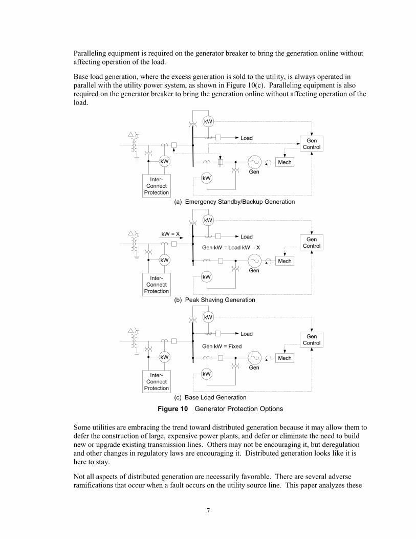
Emergency standby generation is generally not connected in parallel with the utility source, as shown in Figure 10(a), because it is only needed when the utility source is open. Interlocked transfer switches are controlled to open the utility source before closing the generator breaker. However, periodic load testing requires that either the generator be paralleled with the utility power system for a short period of time, or a portion of the customer load must be isolated so it can be connected to the generation for testing. Paralleling equipment may, therefore, be required for testing emergency standby generation.
Peak shaving generation is operated in parallel with the utility power system, as shown in Figure 10(b), at least during peak demand periods, and is operated to prevent generating more power than the local load is using, thereby preventing reverse power flow into the utility system.
7
Paralleling equipment is required on the generator breaker to bring the generation online without affecting operation of the load.
Base load generation, where the excess generation is sold to the utility, is always operated in parallel with the utility power system, as shown in Figure 10(c). Paralleling equipment is also required on the generator breaker to bring the generation online without affecting operation of the load.
(a) Emergency Standby/Backup Generation
Gen
kW
Inter-Connect
Protection
kW
kW
Load GenControl
Mech
(b) Peak Shaving Generation
Gen
kW
Inter-Connect
Protection
kW
kW
Load GenControl
Mech
kW = X
Gen kW = Load kW � X
(c) Base Load Generation
Gen
kW
Inter-Connect
Protection
kW
kW
Load GenControl
Mech
Gen kW = Fixed
Figure 10 Generator Protection Options
Some utilities are embracing the trend toward distributed generation because it may allow them to defer the construction of large, expensive power plants, and defer or eliminate the need to build new or upgrade existing transmission lines. Others may not be encouraging it, but deregulation and other changes in regulatory laws are encouraging it. Distributed generation looks like it is here to stay.
Not all aspects of distributed generation are necessarily favorable. There are several adverse ramifications that occur when a fault occurs on the utility source line. This paper analyzes these

8
problems by breaking the condition into two states: paralleled and islanded. It is presumed that all conditions start out in the paralleled state with the utility source breaker(s) closed, generation supplying part or all of the customer load, and if permitted, excess generation supplying utility load as well. Islanding occurs when the utility source breaker opens, leaving the distributed generation, its own load, and whatever portion of utility load is on the line side of the utility source breaker disconnected or islanded from the rest of the system.
The interconnection transformer at the distributed generation site has a significant impact on paralleled and islanded operation, particularly during unbalanced fault conditions. This paper discusses the ramifications of the high-side delta/low-side wye transformer connection because it is commonly used to serve loads without generation. Other transformer winding configurations may be better suited to supplying loads with distributed generation. However, there is no �best� transformer configuration or industry standard. Each transformer configuration has advantages and disadvantages. The system must be designed to maximize the advantages and minimize or eliminate the disadvantages.
It is typically not economically feasible to replace an existing delta-wye transformer simply because distributed generation is installed on the load side of the transformer, so we will focus on what problems may arise and what solutions are available to overcome them.
LINE FAULT PROTECTION At least one ramification of distributed generation is the effect it has on line protection. Adding generation in parallel with the utility power system at a customer load site, beyond a delta-wye transformer, makes the transformer a source of fault current for faults on the utility source line. Figure 11, Figure 13, and Figure 15 show the simplified one-line diagrams and appropriate sequence component network connections for three-phase, phase-to-phase, and phase-to-ground faults, respectively, on the utility line, with parallel generation operating on the wye side of the delta-wye transformer. Figure 12, Figure 14, and Figure 16 show the simplified one-line diagrams and sequence component network connections for the same respective faults after the utility-source line breaker opens.

9
Line
TransformerLoadUtility Source
Substation
Symmetrical Component Diagrams
E1S
Positive-Sequence Network
Z1S Z1L Z1T
Negative-Sequence Network
Z2S Z2L Z2T
Zero-Sequence Network
Z0S Z0L
Z0T
3φ
V1LI1>0 I1>0
I2=0 I2=0
I0=0 I0=0
Gen.
Z1Load
E1G
Z1GI1>0
Z2Load
I2=0Z2G
Z0Load Z0GV0S V0H V0L
S
S
S
S H
H
H
H
L
L
L
L
V2H
V1HV1S
V2S V2L
Line
TransformerLoadUtility Source
Substation
Symmetrical Component Diagrams
E1S
Positive-Sequence Network
Z1S Z1L Z1T
Negative-Sequence Network
Z2S Z2L Z2T
Zero-Sequence Network
Z0S Z0L
Z0T
3φ
V1LI1=0 I1>0
I2=0 I2=0
I0=0 I0=0
Gen.
Z1Load
E1G
Z1GI1>0
Z2Load
I2=0Z2G
Z0Load Z0GV0S V0H V0L
S
S
S
S H
H
H
H
L
L
L
L
V2H
V1HV1S
V2S V2L
Figure 11 Three-Phase Line Fault With Parallel Distributed Generation
Figure 12 Three-Phase Line Fault With Generation and Utility Source Breaker Open
Line
TransformerLoadUtility Source
Substation
Symmetrical Component Diagrams
E1S
Positive-Sequence Network
Z1S Z1L Z1T
Negative-Sequence Network
Z2S Z2L Z2T
Zero-Sequence Network
Z0S Z0L
Z0T
φ �φ
V1LI1>0 I1>0
I2>0 I2>0
I0=0 I0=0
Gen.
Z1Load
E1G
Z1GI1G>0
Z2Load
I2>0Z2G
Z0Load Z0GV0S V0H V0L
S
S
S
S H
H
H
H
L
L
L
L
V2H
V1HV1S
V2S V2L
Line
TransformerLoadUtility Source
Substation
Symmetrical Component Diagrams
E1S
Positive-Sequence Network
Z1S Z1L Z1T
Negative-Sequence Network
Z2S Z2L Z2T
Zero-Sequence Network
Z0S Z0L
Z0T
φ �φ
V1LI1=0 I1=�I2
I2=0
I0=0 I0=0
Gen.
Z1Load
E1G
Z1GI1>0
Z2Load
I2>0Z2G
Z0Load Z0GV0S V0H V0L
S
S
S
S H
H
H
H
L
L
L
L
V2H
V1HV1S
V2S V2LI2=�I1
Figure 13 Phase-to-Phase Line Fault With Parallel
Distributed Generation Figure 14 Phase-to-Phase Line Fault Generation
and Utility Source Breaker Open

10
Line
TransformerLoadUtility Source
Substation
Symmetrical Component Diagrams
E1S
Positive-Sequence Network
Z1S Z1L Z1T
Negative-Sequence Network
Z2S Z2L Z2T
Zero-Sequence Network
Z0S Z0L
Z0T
φ � G
V1LI1>0 I1>0
I2>0 I2>0
I0>0 I0=0
Gen.
Z1Load
E1G
Z1GI1>0
Z2Load
I2>0Z2G
Z0Load Z0GV0S V0H V0L
S
S
S
S H
H
H
H
L
L
L
L
V2H
V1HV1S
V2S V2L
Line
TransformerLoadUtility Source
Substation
Symmetrical Component Diagrams
E1S
Positive-Sequence Network
Z1S Z1L Z1T
Negative-Sequence Network
Z2S Z2L Z2T
Zero-Sequence Network
Z0S Z0L
Z0T
φ � G
V1LI1=0 I1=0
I2=0 I2=0
I0=0 I0=0
Gen.
Z1Load
E1G
Z1GI1>0
Z2Load
I2=0Z2G
Z0Load Z0GV0S V0H V0L
S
S
S
S H
H
H
H
L
L
L
L
V2H
V1HV1S
V2S V2L
Figure 15 Single Phase-to-Ground Line Fault With
Parallel Distributed Generation Figure 16 Single Phase-to-Ground Line Fault With
Generation and Utility Source Breaker Open
Symmetrical component analysis shows us that the distributed generator contributes fault current to all three types of line faults, through the delta-wye transformer, when the utility source breaker is closed and the two sources are operating in parallel. For each fault type, the generator contributes only positive-sequence, or positive- and negative-sequence current to the fault because the delta connected winding permits the flow of positive- and negative-sequence current, and blocks the flow of zero-sequence current.
With the utility source breaker open, the generator only contributes current to three-phase and phase-to-phase line faults. With the utility source ground connection isolated by the open breaker, the delta connected winding opens the zero-sequence current path, blocking current flow for single phase-to-ground line faults.
Not quite as evident are the voltages impressed on the line during parallel and islanded conditions. During unfaulted parallel operating conditions, the solidly grounded utility system keeps the operating voltages within the normal operating voltage triangle, as shown in Figure 17(a). If we open the utility source and operate islanded, the inherent phase-to-ground line and transformer capacitance balances the phase voltage nearly equidistant from ground potential, again as shown in Figure 17(a). Minor unbalance may occur due to unequal spacing and non-transposed line conductors. Note that this unbalance only serves to unbalance the line-to-ground voltages and does not affect the phase-to-phase voltages. Thus, the standing or normal zero-sequence voltage can increase substantially when the utility breaker opens. During ground fault conditions, before the utility substation source breaker trips, the faulted phase voltage collapses, and the unfaulted phase voltages are held close to their nominal, unfaulted voltages by the effectively grounded utility source, as shown in Figure 17(b). By definition, the zero-sequence impedance of an effectively grounded system must be equal to or less than three times the

11
positive-sequence impedance (X0 ≤ 3 � X1). Under worst-case conditions (X0 = 3 � X1), the unfaulted phase-to-ground voltages can rise to 133% of nominal. Many utility source substations include delta-wye transformer sources that result in zero-sequence source impedance being equal to or less than the positive-sequence source impedance. Phase-to-ground faults near these substations result in virtually no overvoltage on the unfaulted phases.
Should the utility source breaker trip before the distributed generation trips; the line is energized through only the delta-wye transformer. For this condition, the delta winding blocks the flow of zero-sequence current. In some cases, the reduction in current can cause an arcing fault to self-extinguish and the line remains energized. In those cases where the arcing fault does not extinguish, or for a bolted fault, the fault current magnitude is so low (supplied only by the distributed line-ground capacitance of the protected line) that it is difficult to detect by simply measuring phase currents. For this phase-to-ground fault condition, the apparent neutral shifts, and establishes the voltage triangle shown in Figure 17(c).
A
C B
VAN
N, G
VBN
VCN
(a) (b)C B
N
A, G
VAN
VBNVCN
C B
A, N, G
VBN=VBGVCN=VCG
(c) Figure 17 Voltage Phasor Diagrams for the System of Figures 10 through 15: (a) Unfaulted
System, (b) Faulted System (Solid A-Phase Fault, RF = 0) During Paralleled Operation, and (c) Faulted System (Solid A Phase Fault, RF = 0) During Islanded Operation
The voltage triangle shown in Figure 17(c) has normal phase-to-phase voltage magnitude and angle between all phases. The phase-to-ground voltage magnitude on the faulted phase is zero. However, the voltage magnitude on the two unfaulted phases increases to the equivalent of phase-to-phase voltage, which is approximately 1.73 times the normal phase-to-ground voltage. This results in an overvoltage on any phase-to-ground connected equipment on the two unfaulted phases. Phase-to-ground connected distribution transformers, designed to operate within normal phase-to-ground voltage range, can saturate. Distribution class arresters, also connected phase-to-ground, may conduct. This condition creates power quality problems for customers served from this line, and poses risk of equipment damage. This condition must be avoided, if possible, or minimized to the shortest possible duration by tripping the distributed generation as quickly as possible.
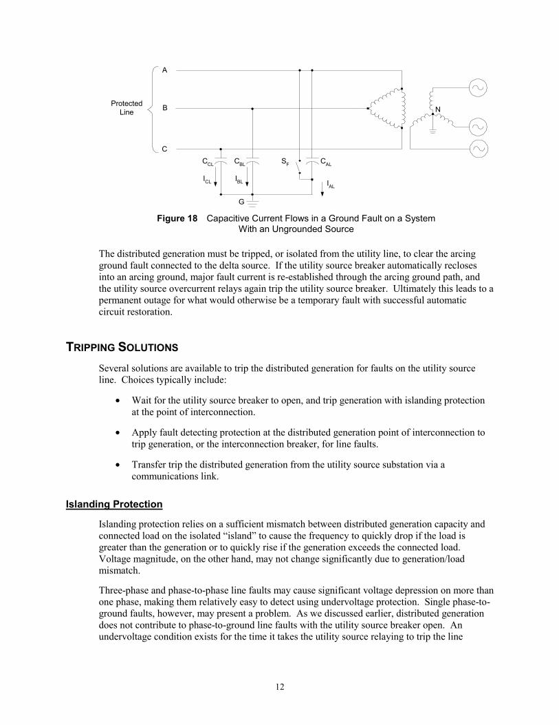
With the utility source disconnected, you might expect that a temporary arcing ground fault would extinguish itself because the only major source of fault current has been removed. However, current continues to flow in the ground fault because of inherent circuit capacitance, as shown in Figure 18 [1]. If the capacitive current flow in the arcing ground fault is less than a few amps, the fault may self-extinguish. Capacitive current flow greater than a few amps is unlikely to self-extinguish because of the high transient recovery voltages associated with capacitive currents. Long overhead lines, or lines with considerable underground cable, are likely to have sufficient charging current to prevent self-clearing.
12
A
C
G
CBL
ProtectedLine
IBL
CCL
ICL
SF CAL
IAL
B N
Figure 18 Capacitive Current Flows in a Ground Fault on a System
With an Ungrounded Source
The distributed generation must be tripped, or isolated from the utility line, to clear the arcing ground fault connected to the delta source. If the utility source breaker automatically recloses into an arcing ground, major fault current is re-established through the arcing ground path, and the utility source overcurrent relays again trip the utility source breaker. Ultimately this leads to a permanent outage for what would otherwise be a temporary fault with successful automatic circuit restoration.
TRIPPING SOLUTIONS Several solutions are available to trip the distributed generation for faults on the utility source line. Choices typically include:
• Wait for the utility source breaker to open, and trip generation with islanding protection at the point of interconnection.
• Apply fault detecting protection at the distributed generation point of interconnection to trip generation, or the interconnection breaker, for line faults.
• Transfer trip the distributed generation from the utility source substation via a communications link.
Islanding Protection
Islanding protection relies on a sufficient mismatch between distributed generation capacity and connected load on the isolated �island� to cause the frequency to quickly drop if the load is greater than the generation or to quickly rise if the generation exceeds the connected load. Voltage magnitude, on the other hand, may not change significantly due to generation/load mismatch.
Three-phase and phase-to-phase line faults may cause significant voltage depression on more than one phase, making them relatively easy to detect using undervoltage protection. Single phase-to-ground faults, however, may present a problem. As we discussed earlier, distributed generation does not contribute to phase-to-ground line faults with the utility source breaker open. An undervoltage condition exists for the time it takes the utility source relaying to trip the line

13
breaker, but then the voltage may return to near normal on the secondary side of the delta-wye transformer.
Typical islanding protection is shown in Figure 19. These relay elements are typically set just above and below the nominal frequency and voltage operating ranges to detect abnormal operating conditions. Short time delays of one second or less are typically used to help ride through brief frequency and voltage transients caused by power system faults beyond the utility substation source line or on load circuits within the customer�s facility.
To UtilitySource
32
Generator
Loads
62
27
59
81O
81U
62
62
62
62
1 or 3
Directional Power
Undervoltage
Overvoltage
Overfrequency
Underfrequency
*
* Optional
*
2 or 3
Figure 19 Basic Islanding Protection
The proposed IEEE standard P1547 (draft #10*) includes the interconnection system response requirements listed in Table 1 [2].
Table 1 IEEE P1547 Interconnection System Response Requirements
Response to Abnormal Voltages* Clearing Time*
Voltage less than 50% 0.16 second or less
Voltage between 50% and 88% 2 seconds or less
Voltage between 110% and 120% 1 second or less
Voltage greater than 120% 0.16 second or less
Response to Abnormal Frequency (60 Hz Base)* Clearing Time*
Frequency greater than 60.5 Hz 0.16 second or less
59.8 Hz to 57.0 Hz (adjustable) Adjustable time delay
Frequency less than 57.0 Hz 0.16 second or less
*See latest draft for modifications and complete details.

14
Microprocessor-based relays with multiple voltage and frequency elements are now commonly used to provide basic islanding protection with multilevel settings. Sensitive setting thresholds with longer time delays and less sensitive setting thresholds with shorter time delays are common. Such schemes permit fast response for extreme excursions from nominal operating conditions and slower, more secure response for those conditions closer to normal operating ranges.
Reverse power relays may be added to supplement the over-/ undervoltage and frequency relays where the interconnection normally has a net power import level. Reverse power relays may also be added when the interconnection does not normally export power and the utility line has sufficient attached load to pick up the reverse power relay during islanded conditions. Figure 20 shows the application of an optional directional power relay to detect islanding using a reverse power pickup threshold that is less than the minimum utility line load.
To UtilitySource
32
+�
Utility Line Load
Reverse Power Relay Settings
Reverse Power Pickup Threshold LessThan Utiltiy Line Load
+ Q
� Q
No-TripRegion
TripRegion
+ P� P
Generator
Load
Figure 20 Optional Directional Power Relay Application To Detect
Islanding With Utility Line Load
Figure 21 shows the application of an optional directional power relay to detect islanding when the import power falls below the minimum import level.

15
Loss of Import Power Settings
Forward Power Dropout ThresholdLess Than Minimum Power Import Level
+ Q
� Q
No-TripRegion
TripRegion
+ P� P
To UtilitySource
32
Generator
Load
+�
Figure 21 Optional Directional Power Relay Application To Detect
Islanding For Loss of Import Power
The Effect of Generator Control on Islanding Protection
Generator controls are provided with distributed generation and associated switchgear to control the operation of each generator to meet the customer�s objectives. A few of the more common modes are described below, along with the impact they may have on islanded operation.
Emergency Standby Mode
Emergency standby generator control is designed to restore service to critical customer load when the utility source is lost. Loss of utility voltage is used to automatically start emergency backup generation and operate breakers or transfer switches to switch the customer load from the utility source to the generation through a break-before-make (open) switching transition. Generation is not normally paralleled with the utility source, except for a few cycles when, after the utility source is restored, the load is transferred back to the utility source through a make-before-break (closed) switching transition. No special interconnect protection is required or warranted for emergency standby generation that is, by definition, not paralleled with the utility source for more than a few cycles.
Peak Shaving Mode
Distributed generation used for peak shaving supplies a portion of the customer load, thereby leveling, or flattening, the load supplied by the utility. For example, if the maximum customer load is 1000 kW and the generator has a 500 kW capacity, the peak shaving control can be set to limit the utility supply to 500 kW. The peak shaving control automatically adjusts generator kilowatt output to keep the utility supply at a flat 500 kW.
In this mode, the generator is always supplying less power than the customer load demands. When the utility source is lost, the deficit generating condition immediately causes the frequency to decrease, which should trigger the islanding protection to trip the generator(s) or the main interconnect breaker.
16
Base Load Mode
In base load mode, the power output from each generator is fixed at up to its maximum continuous kilowatt rating. The control monitors the generator�s kilowatt output and controls the prime-mover fuel supply to maintain constant kilowatt output from the machine. When the utility source is lost, the mismatch between generation output and existing load immediately results in a frequency change. The frequency increases if there is excess generation (customer was exporting power), and the frequency decreases if there is a generation deficiency (customer was importing power). The control makes no attempt to control frequency.
Droop Mode
Droop is defined as a decrease in speed setting as the load increases. Without droop, governor action can cause unstable speed oscillations. Operating in the droop mode, as the load increases, the speed setting decreases. When the governor moves to correct for the speed decrease caused by increased load, it corrects to a lower speed setting, which prevents the speed from over shooting. A droop setting of 3% to 5% is common. Based on 5% droop, increasing the speed setting to 61.5 Hz will produce 50% power output at 60 Hz (frequency established and controlled by the utility). If the speed setting is increased to 63 Hz, the power output will be 100%. If the utility frequency varies, the amount of output power will vary inversely. If the utility frequency increases, the droop line will cross the higher utility frequency line closer to zero power and produce a lower power output. If the utility frequency decreases, the droop will cross the lower utility frequency line further from zero, producing a higher power output [7].
Isochronous Mode
A generator operating in isochronous mode attempts to maintain a constant frequency. A single machine, operating as an isolated unit, may be operated in isochronous mode. One machine in a group of machines operating in an isolated system may be operated in isochronous mode. The other machines are commonly operated in droop mode. The isochronous mode machine is considered the swing machine that varies its power output to control system frequency. The utility system is considered the swing machine for distributed generation operated in parallel with the utility system. When paralleled with the utility, distributed generation should not be operated in isochronous mode. However, when the interconnecting breaker is open, one of the distributed generators is typically switched to isochronous mode.
Fault Detection at the Point of Interconnection
Interconnection Protection
Figure 22 shows a complement of protective relaying that may be needed for complete interconnection protection. This relaying serves several purposes.
Without distributed generation, nondirectional overcurrent relays (device 51) are commonly applied on the low-side transformer main breaker to detect bus and feeder faults. After adding distributed generation to the customer site, the nondirectional overcurrent protection is still needed to detect bus and feeder faults, but may not have adequate sensitivity to detect the generator�s current contribution, in the reverse direction, to internal transformer and utility line faults. The concern for this depends greatly on the available short circuit contribution from the generator, and whether other protection elements, like phase current unbalance (device 46), phase
17
voltage unbalance (device 47), phase undervoltage (device 27), or phase overvoltage (device 59) provide sufficient fault sensitivity and speed to trip the main breaker in time to prevent thermal damage to unfaulted equipment, or other undesirable consequences. The delta-wye transformer impedance limits the generator contribution for faults on the utility line.
If used, directional overcurrent relays (device number 67) need to detect faults on the high side of the delta-wye transformer, and provide backup transformer protection. Directional phase overcurrent relays, if used alone, need to be set sensitively enough to detect three-phase, phase-to-phase, and phase-to-ground high-side faults. This may require extremely sensitive settings that will limit reverse power flow, if that is allowed. Blinders, or load-encroachment torque control, may be used to maintain sensitive reverse phase directional overcurrent relay settings and still accommodate reverse load flow. Load encroachment torque control is also helpful to avoid tripping for current in the forward direction during leading power factor conditions.
Reverse looking phase distance relay elements may also be used instead of the sensitive reverse directional phase overcurrent relays where fixed reach and better loading capability are needed. The phase distance relays see three-phase and phase-to-phase faults through the delta-wye transformer, but not phase-to-ground faults. Also, phase-to-phase faults, on the other side of a delta-wye transformer, may appear to phase mho distance relay elements to be significantly further away than a three-phase fault at the same location [3]. Phase comparator distance elements provide a consistent reach for both phase-to-phase and three-phase faults, seen through a delta-wye transformer, and may, therefore, be a better choice.
Reverse directional negative-sequence overcurrent relays may be used to detect phase-to-phase and phase-to-ground faults on the high side of the delta-wye transformer, relegating the reverse directional phase overcurrent relays to sensing the higher magnitude three-phase faults. The negative-sequence overcurrent element is ideally suited for use with the delta-wye transformer because negative-sequence current flows for all unbalanced faults. However, as we discussed earlier, negative-sequence current only flows for high-side ground faults as long as the utility source breaker is closed and contributing to the fault. Once the utility source breaker opens, there is no way to detect that a high-side ground fault still exists, using current or voltage measurement techniques on the low side of the transformer.

18
To UtilitySource
51
Generator
Loads
67
47
27
59
Directional Power
Directional OC orDistance (21)
Phase CurrentUnbalance
Non-Directional OC
*
* Optional
46
32
1 or 3
*
IslandingProtection
EquipmentProtection
Fault Protection
81O
81U
27/59
Phase VoltUnbalance
Phase Under-Voltage
Phase Over-Voltage
OverFrequency
UnderFrequency
or 59N or27A, B, C and59A, B, C
2531 or 3 2 or 3
25
Figure 22 Typical Distributed Generation Interconnect Protection
To detect sustained ground faults on the high side of the delta-wye transformer, single-phase or three-phase VTs are needed on the high side of the transformer. A common application using a single-phase transformer, connected phase-to-ground, is shown in Figure 23. This application uses a single-phase under-/ overvoltage relay element (device 27/59) to detect a ground fault. As discussed earlier, the faulted phase voltage is zero, and the unfaulted phase voltages are 1.73 times nominal, when supplied from a delta source. The undervoltage element can be set at some fraction of nominal voltage, 50%, for example. The overvoltage element can be set above nominal voltage, 130%, for example. The undervoltage element picks up if the fault is on the same phase as the VT connection, and the overvoltage element picks up if the fault is on one of the other two phases. A timer is generally required to provide a coordinating time delay on the output of the undervoltage element because the undervoltage condition could be the result of a fault external to the utility source line. Sufficient time delay must be used to permit external faults to clear before tripping. The need for an extended coordinating time delay on the overvoltage element is unnecessary because sustained high voltage above the overvoltage relay pickup level can only occur after the utility source breaker opens. A short time delay, around a few cycles, should be sufficient to ride through any high voltage transients caused by lightning and switching surges. Fast tripping can be accomplished for faults on the two phases that the VT is not connected to.
The single-phase voltage transformer is exposed to 1.73 times the nominal phase-to-ground voltage, so it should be rated for line-to-line voltage, even though it is connected phase-to-ground. If the magnetizing impedance of the transformer is approximately the same as the shunt capacitive reactance of the corresponding phase, ferroresonance is possible. Recommended practice calls for a loading resistor connected in parallel with the under-/ overvoltage relay to

19
damp resonant oscillations [5]. Note that this scheme has a significant ground fault sensitivity limitation. In addition, blown potential fuse conditions are difficult to differentiate from solid ground faults. Overcoming these limitations requires additional VTs.
0
(F2, F3)
27/59
F2
F3
F1
No Fault
F1
F2
F3
27
�
�
�
X
59
�
X
X
� 27 59
VNOM
(No Fault)
(F1)
1.73 � VNOM
Voltage
Figure 23 Single-Phase Ground Fault Detection
Figure 24 shows three-phase VTs connected in a wye/broken delta connection. With this connection, 3V0 zero-sequence voltage develops across the terminals of the broken delta windings. A single overvoltage element, 59N, connected across the broken delta terminals provides excellent ground fault detection. Under normal unfaulted conditions, there is no voltage across the open corner of the broken delta winding:
3V0 = VA + VB + VC = 1 ∠0° + 1 ∠�120° + 1 ∠120° = 0
During paralleled operation, a solid ground fault produces 1 per unit of 3V0 zero-sequence voltage across the broken delta connection:
3V0 = VA + VB + VC = 0 + 1 ∠�120° + 1 ∠120° (assuming a phase A fault) = 1 ∠180°
During islanded operation, a single phase-to-ground line fault produces 3 per unit 3V0 zero-sequence voltage across the broken delta connection:
20
3V0 = VA + VB + VC = 0 + 1.73 ∠�150° + 1.73 ∠150° = 3 ∠180°
Setting the 59N pickup threshold above 1 per unit and below 3 per unit provides secure detection for a sustained ground fault during an islanded condition. There is no need for an extended coordinating time delay, so fast tripping can be accomplished for a ground fault on any phase.
Each of the three single-phase voltage transformers may be exposed to 1.73 times nominal phase-to-ground voltage during an islanded condition, so they should be rated for line-to-line voltage, even though they are connected phase-to-ground. If the magnetizing impedance of each transformer is approximately the same as the shunt capacitive reactance of the corresponding phase, ferroresonance is possible. Recommended practice calls for a loading resistor connected in parallel with the 59N relay to dampen resonant oscillations [5].
The broken-delta VT connection has some disadvantages that warrant review, but are not directly relevant to this discussion. Appendix A includes a more detailed discussion about the broken-delta VT connection.
No Fault
F1
F2
F3
59N
�
X
X
X
59N
F2
F3
F1
3V0
3V03pu
3V01pu
IslandedParalleled
0
59N
(No Fault)
Islanded(F1, F2, F3)
3V0
Paralleled(F1, F2, F3)1
3
Figure 24 Three-Phase Ground Fault Detection With Broken Delta VT

21
Figure 25 shows three-phase VTs connected in a wye-wye connection. Individual phase overvoltage relay elements (59A, 59B, and 59C) are connected to their respective secondary phases. For solid ground faults, this connection offers faulted phase identification by knowing which phases experience high voltage during an islanded condition. This protection can be supplemented with individual phase undervoltage elements (27A, 27B, and 27C). Like the previous two connections, there is no need for an extended coordinating time delay, so fast tripping can be accomplished for a ground fault on any phase.
And, like the previous connection, each of the three single-phase voltage transformers may be exposed to 1.73 times the nominal phase-to-ground voltage during an islanded condition, so they should be rated for line-to-line voltage, even though they are connected phase-to-ground. If the magnetizing impedance of each transformer is approximately the same as the shunt capacitive reactance of the corresponding phase, ferroresonance is possible. Recommended practice calls for a loading resistor connected to each secondary phase to dampen resonant oscillations [5].
59
F2
F3
F1
No Fault
F1
F2
F3
27
�
A
B
C
59
�
B, C
A, C
A, B0
B
C
A
59 59
B CA
59
VNOM
(No Fault)
1.73 � VNOM
Voltage
Figure 25 Three-Phase Ground Fault Detection With Faulted Phase ID
22
Communications-Based Solutions
Communication between the utility source substation and the distributed generation site provides backup for islanding protection and assurance that the distributed generation is indeed disconnected from the utility system before the utility source breaker is reclosed, as shown in Figure 26. The communications link is set up to directly transfer trip either the customer main interconnect breaker or the generator breaker(s) when the utility source breaker trips. In the other direction, the status of the customer main interconnect breaker and/or generator breaker status is sent to the utility source substation to confirm that the distributed generation source is isolated before reclosing the substation line breaker. This information can also be linked to the utility SCADA system to provide status information to utility operators. Traditional communications links required to accomplish this communication can be expensive, but new, more affordable communications options are available.
79 Generator
TxTrip Rx
Tx 52aStatusRx (Optional)
Tx GenStatusRx
S
SCADA
Trip
Figure 26 Communications-Assisted Tripping and Monitoring
For short distances, a fiber-optic communications channel offers excellent speed and immunity from ground potential rise and electromagnetic interference. Direct communication between the relays at each site can be established through fiber-optic transceivers that plug directly into the communications port on selected relays or into remote I/O devices that can be wired to devices with conventional contact inputs and outputs.
Unlicensed spread spectrum radio offers another option if the two sites are within about 10 miles of each other, and a line-of-sight path exists between them. Spread spectrum radio, while not quite as fast as a fiber channel, has very good speed and excellent immunity to ground potential rise and electromagnetic interference generated by power system faults and switching transients. Radios are available that interface directly with selected relays and remote I/O devices.
Licensed spread spectrum radio or other radio bands in the licensed microwave bandwidth can also be used. These offer higher transmitting power with greater range but at a significant increase in cost.
The selected relays and remote I/O devices transmit and receive messages with encoded data bits that follow the status of internal relay elements, inputs, or outputs, making it easy to define the desired conditions for monitoring, tripping, and reclosing. The relays and remote I/O devices include messaging security to prevent undesirable false trips due to corrupted messages.
For sites with large generators, some utilities have chosen to install SCADA Remote Terminal Units (RTUs) at the customer site.

23
AUTOMATIC RECLOSING AND SYNCHRONISM CHECK Automatic reclosing time delays at the utility substation may need to be extended to accommodate islanding protection tripping times. This helps ensure that the line breaker does not reclose before the distributed generation is off line. If a communications circuit is used to transfer-trip the generation, as discussed earlier and shown in Figure 26, the same communications circuit may be used to confirm that the generation is off line before permitting the breaker to close.
Sensing line voltage at the utility substation is another method to check if generation is off line before attempting an automatic or manual reclose. Sensing line voltage with a single phase-to-ground connected VT is not adequate because the line may still be energized with a phase-to-ground fault on the sensing phase. As discussed earlier, the uncleared ground fault suppresses the line-to-ground voltage on one phase. A phase-to-phase VT is needed to determine if the line is energized or de-energized, as shown in Figure 27.
79 Generator
25
27
LoadPhase-to-PhaseVT
Figure 27 Utility Substation Autoreclosing and Synchronism Check
With Parallel Distributed Generation
The phase-to-phase line voltage can also be used in conjunction with the utility substation bus voltage to perform a synchronism check across the line breaker. Although highly improbable, if the distributed generation is still on line and close to synchronous speed, the synchronism check relay element will permit breaker closing when the two systems are within the phase angle and voltage difference window permitted by the synchronism relay settings. A synchronism check relay that compensates for slip frequency and breaker close time is needed if breaker closing at �top-dead-center� is desired to minimize closing shock to the asynchronous systems.
UTILITY SUBSTATION LINE PROTECTION Radial line protection at the utility substation typically consists of nondirectional phase and ground overcurrent relays, shown earlier in Figure 9. The overcurrent relays are set to coordinate with upstream and downstream relays, reclosers, and fuses. Adding parallel-distributed generation to the radial line changes the range of fault current magnitudes seen by the phase overcurrent relays. The nondirectional phase overcurrent relays may need to be converted or replaced with directional phase overcurrent relays, as shown in Figure 28, if reverse fault current magnitude for faults on adjacent lines exceeds the pickup on the nondirectional overcurrent elements. Fault studies that model the generation, utility sources, and system impedances need to be performed to determine if directional overcurrent relays are needed at the utility source substation.
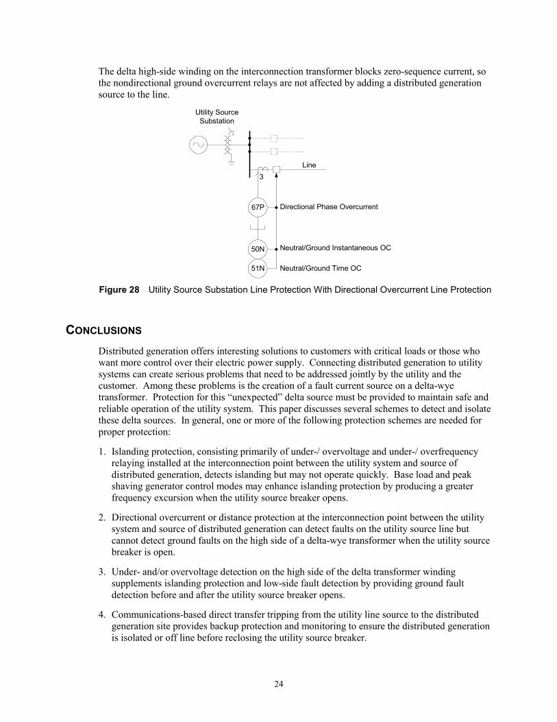
24
The delta high-side winding on the interconnection transformer blocks zero-sequence current, so the nondirectional ground overcurrent relays are not affected by adding a distributed generation source to the line.
Line
Utility SourceSubstation
3
67P
50N
51N
Directional Phase Overcurrent
Neutral/Ground Instantaneous OC
Neutral/Ground Time OC
Figure 28 Utility Source Substation Line Protection With Directional Overcurrent Line Protection
CONCLUSIONS Distributed generation offers interesting solutions to customers with critical loads or those who want more control over their electric power supply. Connecting distributed generation to utility systems can create serious problems that need to be addressed jointly by the utility and the customer. Among these problems is the creation of a fault current source on a delta-wye transformer. Protection for this �unexpected� delta source must be provided to maintain safe and reliable operation of the utility system. This paper discusses several schemes to detect and isolate these delta sources. In general, one or more of the following protection schemes are needed for proper protection:
1. Islanding protection, consisting primarily of under-/ overvoltage and under-/ overfrequency relaying installed at the interconnection point between the utility system and source of distributed generation, detects islanding but may not operate quickly. Base load and peak shaving generator control modes may enhance islanding protection by producing a greater frequency excursion when the utility source breaker opens.
2. Directional overcurrent or distance protection at the interconnection point between the utility system and source of distributed generation can detect faults on the utility source line but cannot detect ground faults on the high side of a delta-wye transformer when the utility source breaker is open.
3. Under- and/or overvoltage detection on the high side of the delta transformer winding supplements islanding protection and low-side fault detection by providing ground fault detection before and after the utility source breaker opens.
4. Communications-based direct transfer tripping from the utility line source to the distributed generation site provides backup protection and monitoring to ensure the distributed generation is isolated or off line before reclosing the utility source breaker.

25
Additional protection, automatic reclosing, and synchronism check functions may be required at the utility source substation. The customer who is adding generation and the utility must discuss and agree upon the necessary changes.
REFERENCES [1] �Review of Ground Fault Protection Methods for Grounded, Ungrounded, and Compensated
Distribution Systems,� Jeff Roberts, Dr. Hector J. Altuve, and Dr. Daqing Hou, Western Protective Relay Conference, October, 2001.
[2] �Draft Standard for Interconnecting Distributed Resources With Electric Power Systems,� IEEE P1547, Draft #10.
[3] SEL Application Guide 96-16, �Applying SEL Distance Relay on Lines With Power Transformers or Open Delta VTs,� Karl Zimmerman, 1996.
[4] �Interconnection Protection of IPP Generators Using Digital Technology,� Charles J. Mozina, Minnesota Power System Conference, November, 1999.
[5] �Protective Relaying, Principles and Practices,� J. Lewis Blackburn, Copyright 1987 by Marcel Dekker, Inc.
[6] �Trip and Restore Distribution Circuits at Transmission Speeds,� Jeff Roberts, Karl Zimmerman, Western Protective Relay Conference, October, 1998.
[7] �Governing Fundamentals (former TA-442),� Woodward Industrial Controls, publication 25195.
BIOGRAPHY Ken Behrendt received a Bachelor of Science Degree in Electrical Engineering from Michigan Technological University in 1970.
From 1970 to 1994, he was employed at Wisconsin Electric Power Company where he worked in Distribution Planning, Substation Engineering, Distribution Protection, and Transmission Planning and Protection.
Since April 1994, he has been employed with Schweitzer Engineering Laboratories as a Field Application Engineer, located in New Berlin, Wisconsin.
Ken is an IEEE Senior Member and an active member of the IEEE Power System Relay Committee, served as the US representative on CIGRE Joint Working Group 34/35.11 on Teleprotection, and is a registered Professional Engineer in the state of Wisconsin. Ken has authored and presented several papers at major power system and protective relay conferences.

26
APPENDIX A
BROKEN DELTA CONNECTION CONSIDERATIONS The measure residual voltage 3V0 (= VA + VB + VC) is useful in performing ground directional control of ground overcurrent protection, 59N protection, and metering. Figure A1 shows a broken-delta VT connection.
VA
VB
VC
ABC
VT SecondariesConnected inBroken Delta
Power System
3V0 = VA + VB + VC
Figure A1 Broken-Delta VT Connection Diagram
The broken-delta VT connection provides zero-sequence voltage for measurement during ground faults. During unfaulted conditions with balanced primary voltage, the output from the broken delta connection is zero. The nominal output voltage for a bolted ground fault on a grounded system is the nominal voltage of each transformer. If the nominal secondary voltage is 120 VAC, the voltage developed across the broken delta for a ground fault on a grounded system is 120 VAC. The nominal output for a bolted ground fault on an ungrounded system is three times the nominal voltage of each transformer. If the nominal voltage of each phase VT is 120 VAC, you can expect 360 VAC from the broken-delta connection for a solid ground fault on an ungrounded system.
Figure A1 shows the common practice of fusing each phase VT primary and secondary lead. A blown primary fuse results in a broken-delta output of nominal voltage. The operation of any one secondary fuse opens the secondary voltage circuit, preventing the broken-delta output from outputting the zero-sequence voltage during a ground fault. If we consider that the normal, non-faulted output is zero and the output during a blown secondary fuse condition is zero, it is obvious that we need a scheme to monitor the health of the VT connection. Figure A2 shows the connection diagram for a patent pending scheme.

27
VA
VB
VC
VN
VaRELAY
ABC
VT SecondariesConnected inBroken Delta
Relay Internal VTPrimaries ConnectedBroken Delta
VbRELAY
VcRELAY
Power System
Figure A2 Single-Line and VT Connection Diagram
With the relay input transformers connected as shown, the relay is able to extract the individual phase voltages. From these phase voltages, the relay can then calculate 3V0. The benefits of this approach are:
1. The relay system can check for blown potential fuses. In a relay using the traditional broken delta connection on a system with little or no unbalance, the 3V0 measurable before and after a blown secondary fuse is the same; i.e. zero volts.
2. The relay can measure each individual phase voltage and calculate the necessary sequence components. This then allows the relay to use the same VTs for phase and ground directional control. Note that the methodologies used for phase and ground directionality are vastly different.
3. Simply add wires from the B- and C-Phase polarity marks of the existing broken delta VT connection to the respective inputs on the relay. It does not require disturbing existing wiring for devices already using the broken-delta voltage output, e.g. you can supply both three-phase secondary voltage and single-phase broken delta voltage from the same VT secondary windings.
4. It allows dual phase directionality from differing VTs: Main 1 could use this new connection from the broken-delta system while Main 2 could use the existing open-delta VTs for polarizing.
28
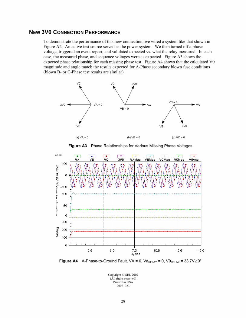
NEW 3V0 CONNECTION PERFORMANCE To demonstrate the performance of this new connection, we wired a system like that shown in Figure A2. An active test source served as the power system. We then turned off a phase voltage, triggered an event report, and validated expected vs. what the relay measured. In each case, the measured phase, and sequence voltages were as expected. Figure A3 shows the expected phase relationship for each missing phase test. Figure A4 shows that the calculated V0 magnitude and angle match the results expected for A-Phase secondary blown fuse conditions (blown B- or C-Phase test results are similar).
VA
VC
VB = 0
3V0
(b) VB = 0
VB
VC
3V0 VA = 0
(a) VA = 0 (c) VC = 0
VC = 0VA
3V0VB
Figure A3 Phase Relationships for Various Missing Phase Voltages
Figure A4 A-Phase-to-Ground Fault, VA = 0, VaRELAY = 0, V0RELAY = 33.7V∠0°
Copyright © SEL 2002 (All rights reserved)
Printed in USA 20021023