Protection and control - Metartec Powering Your Future - Reactors for... · P7-3 Protection and...
14
Reactors for filtering Protection and control
Transcript of Protection and control - Metartec Powering Your Future - Reactors for... · P7-3 Protection and...

Reactors for filtering
Protection and control
P7-2
Reactors for filtering
Introduction · · · · · · · · · · · · · · · · · · · · · · · · · · · · · · · · · · · · · · · · · · · · · · · · · · · · · · · · · · · · · · · · · · · · · · · · · · · · · · · · · · · · · · · · · · · · · · 3
P.7 - Reactors for filtering
Product selection table · · · · · · · · · · · · · · · · · · · · · · · · · · · · · · · · · · · · · · · · · · · · · · · · · · · · · · · · · · · · · · · · · · · · · · · · · · · · · · · · · · · 5
Reactors R / RBReactors III for harmonic rejection filters (for FR) · · · · · · · · · · · · · · · · · · · · · · · · · · · · · · · · · · · · · · · · · · · · · · · · · · · · · · · · · · · · · · · · · · · · · 7
Reactors RE / RBEReactors III for harmonic rejection filters (for FRE static) · · · · · · · · · · · · · · · · · · · · · · · · · · · · · · · · · · · · · · · · · · · · · · · · · · · · · · · · · · · · · · 10
Reactors LR / LRBReactors for filtering for power converters (network side) · · · · · · · · · · · · · · · · · · · · · · · · · · · · · · · · · · · · · · · · · · · · · · · · · · · · · · · · · · · · · · 12

P7-3
Protection and control
Many of the low voltage alteration prob-lems can be corrected with filters. In particular, CIRCUTOR has developed an integral power filter manufacturing program to correct the following prob-lems:
Resonance problems in the LV net-works, caused by the power factor com-pensation equipment
Rejection of harmonics in some parts of the installation
Absorption of harmonics to reduce the distortion rate (THD) of the installa-tion
Limitation of the short-circuit power in some installation points
Filtering of the current absorbed by static converters (speed variators, etc.) in the alternating or direct current side.
CIRCUTOR has the adequate machin-ery to manufacture any type of LV reac-tors, in accordance with the customer's specifications.
Reactors for rejection filters
A series of capacitor capacitor banks with rejection reactors must be installed to compensate the reactive energy in installations with a high content of har-monics.
In this case, the solution entails the ad-dition of a reactor in series with each capacitor, forming a rejection filter with
Reactors for filtering
a resonance frequency that is far away from the harmonic frequencies present in the network.
The purpose of the rejection filter is to prevent the resonance between the in-ductive impedance resulting from the line, power supply transformer and ca-pacitors installed to compensate the power factor and thus prevent an over-load of harmonics in the line and the capacitors.
The filter is composed of various L-C branches, with a special configuration and response curve, as shown in Fig. 1. The complete filter set can be com-posed with any number of branches to compensate the reactive energy present in the installation.
The reactors for this type of filters are specified by the so-called "overvoltage factor", p%, which provides the ration between the reactor and capacitor volt-ages, establishing the resonance of the L-C set. In addition, it tunes a different frequency that is far from harmonic fre-quencies.
p (%) = 100 · UL / UC = 100 · (f / fr)2
UL: Voltage drop in the reactorUC: Resulting voltage in the capacitorf: nominal frequency in the networkfr: serial frequency tuned by the L-C set
P.7
Direct conversion dB / 0.1 Ω to Ω
Z Z Z Z
(dB / 0.1 Ω) Filter (dB / 0.1 Ω) Filter
0 0,100 20 1,00
2 0,125 22 1,25
4 0,158 24 1,58
6 0,199 26 1,99
8 0,251 28 2,51
10 0,316 30 3,16
12 0,398 32 3,98
14 0,501 34 5,01
16 0,630 36 6,30
18 0,794 38 7,94
Setup of the rejection filter
Response in standard frequencies
Table 1: Conversion of dB / 0.1 Ω to Ω

Reactors for filtering
P7-4
The impedances of filters are generally displayed on logarithmic charts, show-ing the impedances related to a stand-ard value in order (in our case 0.1 Ω), depending on the frequency (axis of abcissas). The unit is displayed as (dB / 0.1 Ω) and defined as:
Z (dB / 0.1 Ω) = 20 · log [Z (filter) / 0.1 Ω]
Filter reactors for power converters
The speed regulators for direct and al-ternating current motors (frequency var-iators), UPS systems and, in general, all converters based on thyristors or power transistors, are prone to the generation of alterations in the network or an ex-cessive rippling in the direct current side (motor, in the case of dc regulators). These alterations affect adjoining equip-ment and can even affect the operation of the converter.
The basic types of problems are as fo-llows:
Micro-drops in the voltage and ex-cessive di/dt on the network side with the abovementioned equipment
Current peaks in frequency variators, caused by the connection of capacitors to the direct current stage
Excessive rippling and switching sparks in the motor of dc equipment
All of these problems can be solved with shock reactors or filters, as shown on table 2.
Reactors for absorption filters
These filters are composed of the branches, groups of L-C branches or harmonics being filtered. The resonance frequencies of the different groups are identical to those of the harmonics be-ing filtered.
In construction terms, each branch is similar to that of a rejection filter, but the maximum harmonic current filtered is the important information in this case, so that the inductance and capacitor must be dimensioned for such purposes. There are many different requirements and there are no standard components
available. However, CIRCUTOR can design and manufacture the adequate reactors to cater for any need.
Fig. 2a and 2b show an example of the typical response of two filter branches for harmonics 5 and 7. Fig. 2c shows the response of a bank of filters composed of branches 5, 7, 11, 13 and an overlap-ping stage for n > 15.
Fig.2a. Response in branch frequencies n = 5
Fig.2b. Response in branch frequencies n = 7
Fig.2c. Response in filter frequencies with n = 5, 7, 11, 13, >15
Switching micro-drop filtering in the network and motor
Point PCC
Other loadsInverter
PCC voltage without Lred
PCC voltage with Lred
Motor current without Lmot
Motor current with Lmot
Mains current without Lcc
Mains current with Lcc
Elimination of micro-drops and filtering of harmonics
Other loads
Absortion filter
Commutation choke
Switching improvement inductance in dc
Mains current without Lcc
Mains current with Lcc
Table 1. Filter reactors

Reactors for filtering
P7-5
Reactors III for harmonic rejection filters
R / RB Reactors
Features
Voltage 400 VOn demand: up to 1000 V
Network frequency 50 HzOn demand: 60 Hz
Power rating In accordance with the tableOther values on demand
Value of p % 7 % (189 Hz)Other values on demand
Type of conductor R: copper wireRB: aluminum band
Tolerance L ± 5 %
Linearity (5 % L) 1.8 In
Isolation voltage 4 kV
Maximum room temperature -10 ºC ... +45 ºC
Internal isolation Class F (155 ºC) On demand: class H (180 ºC)
Maximum overload
Permanent 1.17 In
Temporary (1 min) 2 In
Safety
Protection thermostat Opening at 90 ºC
Degree of protection IP 00
Indoor Installation
Standards
UNE-EN-60289, IEC 60076
FeaturesDescription
CIRCUTOR has a standard range of rejec-tion reactors p = 7 %, with a resonance fre-quency of 189 Hz for 50 Hz networks (or on demand 227 Hz for 60 Hz networks). This is the most frequent tuning value to avoid any resonance of the 5th harmonic and above. The set of capacitors-reactors absorbs part of the current of the 5th harmonic and acts as a rejection filter for higher frequencies. In some installations, other values of p % are required, for example 5.6 % (210 Hz), 6 % (204 Hz), 14 % (134 Hz), etc.
CIRCUTOR can build reactors on demand, which will be adapted to any power rating, p %, voltage and frequency.
Low-powered reactors, R type, are built with plates with low losses and are coiled with a copper conductor. The connection is achieved with the adequate terminals. In the case of higher power ratings, RB reactors are used, with a magnetic plate nucleus and mul-tiple steel cores, which offer excellent charac-teristics and a low loss ratio. Aluminum band coils are used (or copper band, on demand) and the input and output connections run through a plate.
Both R and RB type reactors have a vacuum varnish sealing to increase the insulation, providing a greater mechanical resistance and reduce the level of noise.
Application
The rejection reactors of the R / RB series have been specially designed for their use in capacitor banks in installations with a high harmonic content. The reactors must be con-nected in series to each capacitor for the ad-equate protection of capacitors and to avoid the resonance effects in the installation.

Reactors for filtering
P7-6
Reactors III series RX / RBX at 400 Vac, 50 Hz, p = 7 % (189 HZ)
For capacitors: kvar In (A) L (mH) Losses Weight (kg) Type Code
CF 46 / 7.5 6,25 9 6,12 36 W 8 RX-6.25-400 P7101F
CF 46 / 15 12,5 18 3,06 53 W 9,2 RX-12.5-400 P71013
CF 46 / 25 20 30 1,92 76 W 11,5 RX-20-400 P71015
CF 46 / 30 25 37 1,53 92 W 15 RX-25-400 P71016
CF 46 / 50 40 60 0,95 145 W 20 RBX-40-400 P71018
CF 46 / 63 50 75 0,76 187 W 26 RBX-50-400 P71019
References
DimensionsReactors III for harmonic rejection filtersR / RB Reactors
RX - 7% RBX - 7%
Type a b c d e f g
RX-6.25-400 180 102 190 90 75 7 --
RX-12.5-400 180 112 192 90 85 7 --
RX-20-400 180 122 190 90 95 7 --
RX-25-400 180 137 196 90 110 7 --
RBX-40-400 292 124 231 160 110 9 175
RBX-50-400 292 144 232 160 110 9 175
R - 7% RB - 7%
Type a b c d e f g
R-5-400 155 112 165 75 85 7 --
R-10-400 180 102 190 90 75 7 --
R-15-400 180 112 190 90 85 7 --
R-20-400 260 124 174 150 90 7 150
R-25-400 260 124 174 150 90 7 150
R-30-400 290 124 231 160 90 9 150
R-40-400 293 124 231 160 90 9 150
R-50-400 310 144 233 160 110 9 175
R-60-400 305 146 260 160 110 11 180
R-80-400 335 155 280 180 120 11 185
R-100-400 338 170 300 180 135 11 215
R-120-400 355 170 350 200 135 13 220
R - 14% RBC - 14%
Type a b c d e f g
R-5-400-14% 180 102 197 90 75 7 -
R-10-400-14% 180 122 197 90 95 7 -
R-12.5-400-14% 180 137 197 90 110 7 -
R-15-400-14% 250 122 250 130 90 9 -
R-20-400-14% 250 132 250 130 100 9 -
R-25-400-14% 250 147 256 130 115 9 -
RBC-30-400-14% 285 154 233 160 120 9 181
RBC-40-400-14% 290 159 233 160 125 9 184
RBC-50-400-14% 307 164 233 180 130 9 194
RBC-60-400-14% 335 196 280 280 150 11 197

Reactors for filtering
P7-7
ConnectionsReactors III for harmonic rejection filtersR / RB Reactors
References
Reactancia
Condensador
Reactors III series R / RB at 400 Vac, 50 Hz, p = 7 % (189 HZ)
For capacitors: kvar In (A) L (mH) Losses Weight (kg) Type Code
CF 46 / 6 5 7,5 7,66 25 W 6 R-5-400 / R-6-460 P70110
CF 46 / 12.5 10 15 3,83 50 W 8 R-10-400 / R-12,5-460 P70115
CF 46 / 19 15 22 2,55 57 W 9,5 R-15-400 / R-19-460 P70117
CF 46 / 25 20 30 1,92 76 W 14 RB-20-400 / RB-25-460 P70125
CF 46 / 30 25 37 1,53 90 W 14 RB-25-400 / RB-30-460 P70130
CF 46 / 37 30 45 1,27 120 W 19 RB-30-400 / RB-37-460 P70135
CF 46 / 50 40 60 0,95 145 W 20 RB-40-400 / RB-50-460 P70140
CF 46 / 62 50 75 0,76 185 W 27 RB-50-400 / RB-62-460 P70145
CF 46 / 74 60 90 0,63 205 W 31 RB-60-400 / RB-74-460 P70150
CF 46 / 100 80 120 0,47 235 W 38 RB-80-400 / RB-100-460 P70155
CF 46 / 62 x 2 100 145 0,38 250 W 50 RB-100-400 / RB-120-460 P70160
CF 46 / 74 x 2 120 175 0,32 295 W 58 RB-120-400 / RB-148-460 P70165
Reactors III series R / RBC at 400 Vac, 50 Hz, p = 14 % (134 HZ)
For capacitors: kvar In (A) L (mH) Losses Weight (kg) Type Code
CF -50 / 7 5 7,5 16,31 31 W 9,5 R-5-400-14% / R-6-460-14% P70110 00 003
CF -50 / 14 10 15 8,15 61 W 13 R-10-400-14% / R-12,5-460-14% P70115 00 003
CF -50 / 17 12,5 18 6,52 65 W 16 R-12,5-400-14% / R-15-460-14% P70117 00 003
CF -50 / 21 15 22 5,43 71 W 21,5 R-15-400-14% / R-19-460-14% P70120 00 003
CF -50 / 27 20 30 4,07 110 W 25 R-20-400-14% / R-25-460-14% P70125 00 003
CF -50 / 34 25 37 3,26 112 W 30,5 R-25-400-14% / R-30-460-14% P70130 00 003
CF -50 / 41 30 45 2,71 146 W 35 RBC-30-400-14% / RBC-37-460-14% P70135 00 003
CF -50 / 55 40 60 2,03 181 W 41 RBC-40-400-14% / RBC-50-460-14% P70140 00 003
CF -50 / 69 50 75 1,63 225 W 48 RBC-50-400-14% / RBC-62-460-14% P70145 00 003

Reactors for filtering
P7-8
Reactors III for static capacitor banksReactors RE / RBE
Application
The rejection reactors of the RE / RBE se-ries have been specially designed for their use in capacitor banks in installations with a high harmonic content. The reactors must be connected in series to each capacitor for the
FeaturesDescription
CIRCUTOR has standardized the reactors of the RE / RBE series, with a special design for their use in static capacitor banks. The best operation of the set requires the reactors to be connected within the triangle composed by the capacitor-reactor set. At the same power rating, the RE / RBE reactors have a nominal current value that is 1.73 times smaller and an inductance value that is 3 times greater than that in an R / RB reactor.
The company has a standard range of 400 V rejection reactors with p = 7 %, with a reso-nance frequency of 189 Hz for 50 Hz networks (or on demand 227 Hz for 60 Hz networks). In addition, reactors can be manufactured on demand for static capacitor banks adapted to any value of the power rating, p %, voltage and frequency.
Low-powered reactors, RE type, are built with plates with low losses and are coiled with copper wire. The connection is achieved with the adequate terminals. In the case of higher power ratings, RBE reactors are used, with a magnetic plate nucleus and multiple steel cores, which offer excellent characteristics and a low loss ratio. The coils are made with an aluminium band (or copper band, on de-mand). The input and output connections run through a plate.
Both RE and RBE type reactors have a vacu-um varnish sealing to increase the insulation and reduce the levels of noise.
Features
Voltage 400 VOn demand: up to 1000 V
Network frequency 50 HzOn demand: 60 Hz
Power rating In accordance with the tableOther values on demand
Value of p % 7 % (189 Hz)Other values on demand
Type of conductor RE: copper wireRBE: aluminum band
Tolerance L ± 5 %
Linearity (5 % L) 1.8 In
Isolation voltage 4 kV
Maximum room temperature -10 ºC ... +45 ºC
Internal isolation Class F (155 ºC) On demand: class H (180 ºC)
Maximum overload
Permanent 1.17 In
Temporary (1 min) 2 In
Safety
Protection thermostat Opening at 90 ºC
Degree of protection IP 00
Indoor Installation
Standards
UNE-EN-60289, IEC 60076
adequate protection of capacitors, the static operations module and to avoid the reso-nance effects in the installation.

Reactors for filtering
P7-9
Reactors III series RE / RBE at 400 Vac, 50 Hz, p = 7 % (189 HZ)
For capacitors: kvar In (A) L (mH) Losses (W) Weight (kg) Type Code
CF 46 / 6-6B 5 5 23,67 25 6 RE-5-400 / RE-6-460 P70210
CF 46 / 12.50.6B 10 9 11,27 50 8 RE-10-400 / RE-12,5-460 P70215
CF 46 / 19-6B 15 13 7,50 57 9,5 RE-15-400 / RE-19-460 P70220
CF 46 / 25-6B 20 17 5,68 76 11,5 RE-20-400 / RE-25-460 P70225
CF 46 / 30-6B 25 21 4,68 90 17 RE-25-400 / RE-30-460 P70230
CF 46 / 37-6B 30 26 3,84 120 20,5 RE-30-400 / RE-37-460 P70235
CF 46 / 50-6B 40 35 2,84 145 25,5 RE-40-400 / RE-50-460 P70240
CF 46 / 62-6B 50 42 2,29 185 29 RBE-50-400 / RBE-62-460 P70245
CF 46 / 74-6B 60 51 1,89 205 30 RBE-60-400 / RBE-74-460 P70250
CF 46 / 100-6B 80 68 1,42 235 41 RBE-80-400 / RBE-100-460 P70255
References
DimensionsReactors III for static capacitor banksReactors RE / RBE
RE RBE
Type a b c d e f g
RE-5-400 155 92 165 75 75 7 --
RE-10-400 180 102 190 90 75 7 --
RE-15-400 180 112 190 90 85 7 --
RE-20-400 180 122 190 90 95 7 --
RE-25-400 240 122 250 130 90 9 --
RE-30-400 240 132 250 130 100 9 --
RE-40-400 240 147 250 130 115 9 --
RBE-50-400 310 154 233 160 120 9 185
RBE-60-400 310 154 234 160 120 9 185
RBE-80-400 338 165 280 180 130 11 195
Connections
Reactancia
Condensador

Reactors for filtering
P7-10
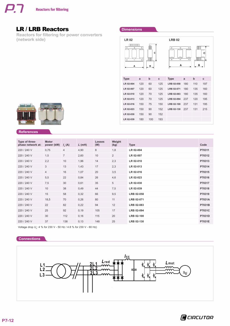
Reactors for filtering for power converters (network side)
LR / LRB Reactors
Application
The reactors of the LR / LRB series are pre-pared and can be used on the network and motor sides. They attenuate micro-drops and peaks during the initial connection and switching operations, and they reduce the rate of harmonics from the network current.
FeaturesDescription
The motor speed regulation equipment, fre-quency variators, UPS units, etc. generate alterations in the network, which affect other loads in the installation of the operation of the equipment.
The LR / LRB reactors connected to the input on the network side of the equipment can attenuate voltage peaks and reduce the harmonic distortion generated by the power electronics. The LR / LRB Reactors for filter-ing can reduce the current harmonics in any converter from 40... 50 % to values around 20 %. In addition, they reduce the short-circuit current and increase the safety of the converter's semi-conductors. When installed on the motor side, they can attenuate har-monic frequencies caused during switching operations.
Low-powered reactors, LR type, are built with plates with low losses and are coiled with copper wire. The connection is achieved with the adequate terminals. In the case of higher currents, LRB reac-
tors are used, with a magnetic plate nucleus and multiple steel cores, which offer excellent characteristics and a low loss ratio. Copper band coils (or aluminium band, on demand). The connections run through a plate. Both LR and LRB type reactors have a
vacuum varnish sealing to increase the insu-lation, providing a greater mechanical resist-ance and reduce the level of noise.
Features
Voltage drop Uk % (LR 04: 400 V or Lr 02: 230 V)
4 % network at 50 Hz (4.8 % network at 60 Hz)Other values on demand
Voltage Up to 1000 Vac
Value of L (mH) In accordance with the tableOther values on demand
Nominal current In accordance with the tableOther values on demand
Type of conductor LR: copper wireLRB: copper band (or aluminium, on demand)
Tolerance L ± 5 %
Linearity (5 % L) 1.5 In
Isolation voltage 4 kV
Maximum room temperature -10 ºC ... +45 ºC
Internal isolation Class F (155 ºC) On demand: class H (180 ºC)
Maximum overload
Permanent 1.17 In
Temporary (1 min) 2 In
Safety
Protection thermostat On demand
Degree of protection IP 00
Indoor Installation
Standards
UNE-EN-60289, IEC 60076

Reactors for filtering
P7-11
Type of three-phase network at:
Motor power (kW) In (A) L (mH)
Losses (W)
Weight (kg) Type Code
380 / 415 V 0,75 2,5 14,8 6 1,8 LR 04-003 P70301
380 / 415 V 1,5 4 7,90 8 1,8 LR 04-004 P70302
380 / 415 V 2,2 5,5 5,90 10 2 LR 04-006 P70303
380 / 415 V 3 7,5 4,30 12 2 LR 04-008 P70304
380 / 415 V 4 10 3,20 15 2,3 LR 04-010 P70305
380 / 415 V 5,5 13 2,50 18 2,3 LR 04-013 P70306
380 / 415 V 7,5 17 1,85 25 3,5 LR 04-017 P70307
380 / 415 V 11 22 1,47 30 4,6 LR 04-022 P70308
380 / 415 V 15 32 0,98 45 5 LR 04-033 P70309
380 / 415 V 18,5 40 0,80 55 7,5 LR 04-041 P7030A
380 / 415 V 22 47 0,67 64 9 LR 04-050 P7030B
380 / 415 V 25 53 0,59 77 9,5 LR 04-058 P7030C
380 / 415 V 30 64 0,49 88 11 LR 04-066 P7030D
380 / 415 V 37 76 0,40 110 13 LRB 04-080 P7030E
380 / 415 V 45 90 0,34 120 18 LRB 04-095 P7030F
380 / 415 V 55 110 0,28 145 21 LRB 04-115 P7030G
380 / 415 V 75 148 0,20 190 26 LRB 04-150 P7030H
380 / 415 V 90 180 0,17 230 32 LRB 04-185 P7030J
380 / 415 V 110 200 0,15 245 36 LRB 04-200 P7030K
380 / 415 V 132 250 0,12 285 44 LRB 04-250 P7030L
380 / 415 V 160 300 0,10 355 48 LRB 04-300 P7030M
380 / 415 V 200 400 0,07 475 72 LRB 04-400 P7030N
380 / 415 V 250 500 0,06 550 80 LRB 04-500 P7030P
380 / 415 V 315 600 0,05 634 105 LRB 04-600 P7030Q
Voltage drop Uk: 4 % for 400 V - 50 Hz / 4.8 % for 400 V - 60 Hz)
References
DimensionsReactors for filtering for power converters (network side)
LR / LRB ReactorsLR 04 LRB 04
Type a b c Type a b c
LR 04-003 120 60 125 LRB 04-080 180 135 160
LR 04-004 120 60 125 LRB 04-095 237 120 195
LR 04-006 120 60 125 LRB 04-115 237 131 195
LR 04-008 120 60 125 LRB 04-150 237 131 215
LR 04-010 120 70 125 LRB 04-185 242 154 256
LR 04-013 120 70 125 LRB 04-200 245 154 256
LR 04-017 150 75 150 LRB 04-250 285 154 300
LR 04-022 150 90 152 LRB 04-300 280 164 300
LR 04-033 150 90 152 LRB 04-400 320 208 350
LR 04-041 180 100 193 LRB 04-500 320 228 350
LR 04-050 180 110 197 LRB 04-600 385 320 505
LR 04-058 180 110 197
LR 04-066 180 120 197
Reactors for filtering
P7-12
Type of three-phase network at:
Motor power (kW) In (A) L (mH)
Losses (W)
Weight (kg) Type Code
220 / 240 V 0,75 4 4,90 8 1,8 LR 02-004 P70311
220 / 240 V 1,5 7 2,60 10 2 LR 02-007 P70312
220 / 240 V 2,2 10 1,96 14 2,3 LR 02-010 P70313
220 / 240 V 3 13 1,43 17 2,3 LR 02-013 P70314
220 / 240 V 4 16 1,07 20 3,5 LR 02-016 P70315
220 / 240 V 5,5 22 0,84 26 4,6 LR 02-023 P70316
220 / 240 V 7,5 30 0,61 35 5 LR 02-030 P70317
220 / 240 V 10 38 0,49 44 7,5 LR 02-039 P70318
220 / 240 V 15 58 0,32 66 9,5 LRB 02-058 P70319
220 / 240 V 18,5 70 0,26 80 11 LRB 02-071 P7031A
220 / 240 V 22 82 0,22 94 12 LRB 02-083 P7031B
220 / 240 V 25 92 0,19 105 17 LRB 02-094 P7031C
220 / 240 V 30 112 0,16 115 20 LRB 02-100 P7031D
220 / 240 V 37 138 0,13 148 25 LRB 02-130 P7031E
Voltage drop Uk: 4 % for 230 V - 50 Hz / 4.8 % for 230 V - 60 Hz)
References
DimensionsReactors for filtering for power converters (network side)
LR / LRB ReactorsLR 02 LRB 02
Type a b c Type a b c
LR 02-004 120 60 125 LRB 02-058 180 110 197
LR 02-007 120 60 125 LRB 02-071 180 135 160
LR 02-010 120 70 125 LRB 02-083 180 135 160
LR 02-013 120 70 125 LRB 02-094 237 120 195
LR 02-016 150 75 150 LRB 02-100 237 131 195
LR 02-023 150 90 152 LRB 02-130 237 131 215
LR 02-030 150 90 152
LR 02-039 180 100 193
Connections

Reactors for filtering
P7-13