Prosthetics Research and the Engineering Profession · Prosthetics Research and the Engineering...
30
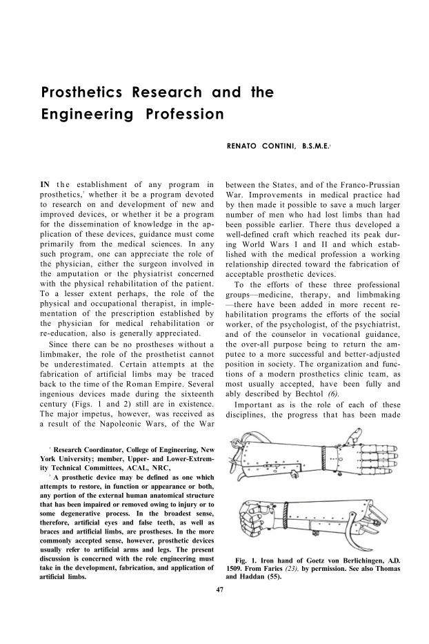
Prosthetics Research and the Engineering Profession RENATO CONTINI, B.S.M.E. 1 1 Research Coordinator, College of Engineering, New York University; member, Upper- and Lower-Extrem- ity Technical Committees, ACAL, NRC, 2 A prosthetic device may be defined as one which attempts to restore, in function or appearance or both, any portion of the external human anatomical structure that has been impaired or removed owing to injury or to some degenerative process. In the broadest sense, therefore, artificial eyes and false teeth, as well as braces and artificial limbs, are prostheses. In the more commonly accepted sense, however, prosthetic devices usually refer to artificial arms and legs. The present discussion is concerned with the role engineering must take in the development, fabrication, and application of artificial limbs. IN the establishment of any program in prosthetics, 2 whether it be a program devoted to research on and development of new and improved devices, or whether it be a program for the dissemination of knowledge in the ap- plication of these devices, guidance must come primarily from the medical sciences. In any such program, one can appreciate the role of the physician, either the surgeon involved in the amputation or the physiatrist concerned with the physical rehabilitation of the patient. To a lesser extent perhaps, the role of the physical and occupational therapist, in imple- mentation of the prescription established by the physician for medical rehabilitation or re-education, also is generally appreciated. Since there can be no prostheses without a limbmaker, the role of the prosthetist cannot be underestimated. Certain attempts at the fabrication of artificial limbs may be traced back to the time of the Roman Empire. Several ingenious devices made during the sixteenth century (Figs. 1 and 2) still are in existence. The major impetus, however, was received as a result of the Napoleonic Wars, of the War between the States, and of the Franco-Prussian War. Improvements in medical practice had by then made it possible to save a much larger number of men who had lost limbs than had been possible earlier. There thus developed a well-defined craft which reached its peak dur- ing World Wars I and II and which estab- lished with the medical profession a working relationship directed toward the fabrication of acceptable prosthetic devices. Fig. 1. Iron hand of Goetz von Berlichingen, A.D. 1509. From Faries (23), by permission. See also Thomas and Haddan (55). To the efforts of these three professional groups—medicine, therapy, and limbmaking —there have been added in more recent re- habilitation programs the efforts of the social worker, of the psychologist, of the psychiatrist, and of the counselor in vocational guidance, the over-all purpose being to return the am- putee to a more successful and better-adjusted position in society. The organization and func- tions of a modern prosthetics clinic team, as most usually accepted, have been fully and ably described by Bechtol (6). Important as is the role of each of these disciplines, the progress that has been made 47
Transcript of Prosthetics Research and the Engineering Profession · Prosthetics Research and the Engineering...
Prosthetics Research and the Engineering Profession
RENATO CONTINI, B.S.M.E.1
1 Research Coordinator, College of Engineering, New York University; member, Upper- and Lower-Extremity Technical Committees, ACAL, NRC,
2 A prosthetic device may be defined as one which attempts to restore, in function or appearance or both, any portion of the external human anatomical structure that has been impaired or removed owing to injury or to some degenerative process. In the broadest sense, therefore, artificial eyes and false teeth, as well as braces and artificial limbs, are prostheses. In the more commonly accepted sense, however, prosthetic devices usually refer to artificial arms and legs. The present discussion is concerned with the role engineering must take in the development, fabrication, and application of artificial limbs.
IN t h e establishment of any program in prosthetics, 2 whether it be a program devoted to research on and development of new and improved devices, or whether it be a program for the dissemination of knowledge in the application of these devices, guidance must come primarily from the medical sciences. In any such program, one can appreciate the role of the physician, either the surgeon involved in the amputation or the physiatrist concerned with the physical rehabilitation of the patient. To a lesser extent perhaps, the role of the physical and occupational therapist, in implementation of the prescription established by the physician for medical rehabilitation or re-education, also is generally appreciated.
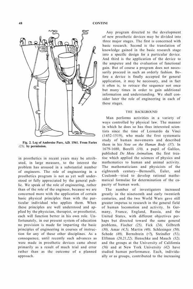
Since there can be no prostheses without a limbmaker, the role of the prosthetist cannot be underestimated. Certain attempts at the fabrication of artificial limbs may be traced back to the time of the Roman Empire. Several ingenious devices made during the sixteenth century (Figs. 1 and 2) still are in existence. The major impetus, however, was received as a result of the Napoleonic Wars, of the War
between the States, and of the Franco-Prussian War. Improvements in medical practice had by then made it possible to save a much larger number of men who had lost limbs than had been possible earlier. There thus developed a well-defined craft which reached its peak during World Wars I and II and which established with the medical profession a working relationship directed toward the fabrication of acceptable prosthetic devices.
Fig. 1. Iron hand of Goetz von Berlichingen, A.D. 1509. From Faries (23), by permission. See also Thomas and Haddan (55).
To the efforts of these three professional groups—medicine, therapy, and limbmaking —there have been added in more recent rehabilitation programs the efforts of the social worker, of the psychologist, of the psychiatrist, and of the counselor in vocational guidance, the over-all purpose being to return the amputee to a more successful and better-adjusted position in society. The organization and functions of a modern prosthetics clinic team, as most usually accepted, have been fully and ably described by Bechtol (6).
Important as is the role of each of these disciplines, the progress that has been made
47
in prosthetics in recent years may be attributed, in large measure, to the interest the problem has aroused in a substantial number of engineers. The role of engineering in a prosthetics program is not as yet well understood or fully appreciated by the general public. We speak of the role of engineering, rather than of the role of the engineer, because we are concerned more with the application of certain basic physical principles than with the particular individual who applies them. When these principles are well understood and applied by the physician, therapist, or prosthetist, each will function better in his own role. Unfortunately, in our present system of education no provision is made for imparting the basic principles of engineering in courses of instruction for any of these other disciplines. As a consequence, until recently such advances as were made in prosthetic devices came about primarily as a result of much trial and error rather than as the outcome of a planned approach.
Fig. 2. Leg of Ambroise Pare, A.D. 1561. From Faries (23), by permission.
Any program directed to the development of new prosthetic devices may be divided into three major stages. The first is concerned with basic research. Second is the translation of knowledge gained in the basic research stage into a specific design for a particular device. And third is the application of the device to the amputee and the evaluation of functional gain. But of course a program does not necessarily proceed in such an orderly fashion. Before a device is finally accepted for general application, it may be necessary, and in fact it often is, to retrace the sequence not once but many times in order to gain additional information and understanding. We shall consider later the role of engineering in each of these stages.
THE BACKGROUND
Man performs activities in a variety of ways controlled by physical law. The manner in which he does so has thus interested scientists since the time of Leonardo da Vinci (1452-1519), who made the first systematic study of human movements and described them in his Note on the Human Body (37). In 1679-1680, Borelli (10), a pupil of Galileo, published De Motu Animalium, the first treatise which applied the sciences of physics and mathematics to human and animal activity. The mathematicians and physicists of the eighteenth century—Bernoulli, Euler, and Coulomb—tried to develop rational mathematical formulae for determination of the capacity of human work.
The number of investigators increased greatly in the nineteenth and early twentieth centuries, and the two World Wars gave still greater impetus to research in the general field of human locomotion and activity. In Germany, France, England, Russia, and the United States, with different objectives perhaps but directed toward the same general problems, Fischer (25), Fick (24), Gilbreth (30), Amar (4,5), Martin (40), Schlesinger (50), Schede (49), Bernshtein (<?), Steindler (51), Elftman (20,21,22), Henschke and Mauch (32), and the groups at the University of California (56) and at New York University (42) have studied human performance. Each, individually or as groups, contributed to the increasing
48 CONTINI
knowledge both in the general areas of human activity and in the specific application of this knowledge to prosthetics.
From the time of Leonardo, almost every investigator in this field either was primarily a physical scientist, or, if not, had a very intimate knowledge of physics and mathematics. In the later period particularly, the major contributors to the increasing knowledge of human performance have been engineers, physical scientists, or anatomists and physiologists with training in the physical sciences. A more comprehensive review of the investigators in this field is that of Contini and Drillis (14).
BASIC RESEARCH IN HUMAN MOTIONS
In the design of any structure or mechanism, for whatever purpose, the engineer usually proceeds from a set of established specifications. These specifications may describe the function of the device, the space it may occupy, the activity it must perform, the forces which may be applied to it and which it must withstand, the chemical and physical damage to which it may be subjected, the working life expected of it, how often it should be overhauled or maintained, and what it may cost. To design a prosthetic device properly, similar specifications should be prepared. Some of the requirements for a satisfactory prosthesis may be developed from known data, that is, from information obtained empirically over extended periods of time and from the experience of countless amputees. Other information, however, and perhaps the more important in the design of prostheses, can come only after systematic experimentation. To supply this information, then, is the purpose of the program in basic research.
Every human movement takes place in time and space and is controlled by external and internal forces and by the mass of the parts involved. The internal forces are generated in the muscles and transmitted through the limbs to tools, controls, instruments, or other objects. The external forces are those of gravity, inertia, ground reaction, and air resistance. When the body is at rest, the external and internal forces are in equilibrium; when it is in motion, the resultant of these forces has some value other than zero.
Of course human movements may be observed and the pattern of movement described subjectively. But unless these movements can be recorded and measured precisely, no true understanding of the movement can be had, nor can repeated movements be compared objectively in the same individual or between different individuals. As technology has moved ahead, engineering knowledge has made it possible to develop instruments and techniques for recording and measuring movements and the forces which affect these movements. Although it would be interesting, as an historical aside, to review the methods used by earlier investigators, it is more profitable to describe some of the recent developments.
METHODS OF MEASUREMENT
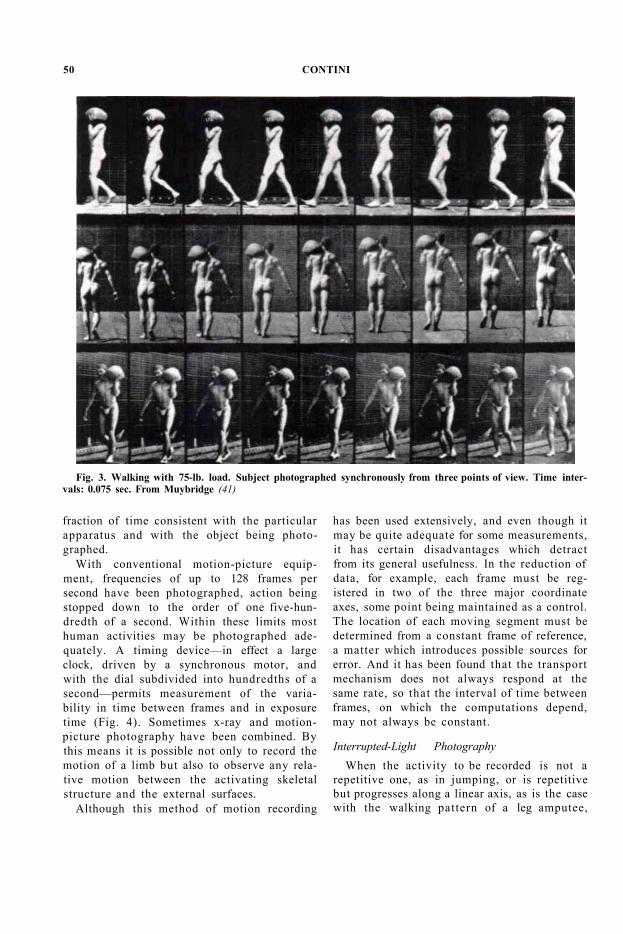
The invention of photography in the middle of the nineteenth century, and the subsequent improvements in photographic techniques, have made it possible to record motions and displacements exactly (Fig. 3). The development of motion-picture photography, of interrupted-light photographic techniques, and of a combination of the two as obtained in the gliding cyclogram has made it possible to measure not only displacement but also the rate and change in rate at which movements occur. By these techniques, then, we can obtain displacement, velocity, and acceleration. Once these quantities are known, and when the mass of the total moving body or of its segments can be obtained by other measures, the forces acting on the body, the energy costs, and the power requirements can all be computed.
Motion-Picture Photography
Of the photographic techniques mentioned, motion-picture photography is used perhaps most universally. By mechanical or electromechanical means, a light-sensitive film is transported at a known, fixed rate past a lens and shutter. The film-transport mechanism is synchronized with the shutter so that a picture is taken each time the film is advanced one frame. The speed at which pictures are taken may be varied between sequences to suit the particular need, and the shutter speed may be varied to stop the action down to the smallest
PROSTHETICS AND ENGINEERING 49
fraction of time consistent with the particular apparatus and with the object being photographed.
With conventional motion-picture equipment, frequencies of up to 128 frames per second have been photographed, action being stopped down to the order of one five-hundredth of a second. Within these limits most human activities may be photographed adequately. A timing device—in effect a large clock, driven by a synchronous motor, and with the dial subdivided into hundredths of a second—permits measurement of the variability in time between frames and in exposure time (Fig. 4). Sometimes x-ray and motion-picture photography have been combined. By this means it is possible not only to record the motion of a limb but also to observe any relative motion between the activating skeletal structure and the external surfaces.
Although this method of motion recording
has been used extensively, and even though it may be quite adequate for some measurements, it has certain disadvantages which detract from its general usefulness. In the reduction of data, for example, each frame must be registered in two of the three major coordinate axes, some point being maintained as a control. The location of each moving segment must be determined from a constant frame of reference, a matter which introduces possible sources for error. And it has been found that the transport mechanism does not always respond at the same rate, so that the interval of time between frames, on which the computations depend, may not always be constant.
Fig. 3. Walking with 75-lb. load. Subject photographed synchronously from three points of view. Time intervals: 0.075 sec. From Muybridge (41)
Interrupted-Light Photography When the activity to be recorded is not a
repetitive one, as in jumping, or is repetitive but progresses along a linear axis, as is the case with the walking pattern of a leg amputee,
50 CONTINI
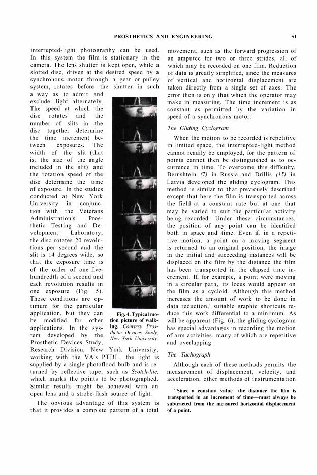
interrupted-light photography can be used. In this system the film is stationary in the camera. The lens shutter is kept open, while a slotted disc, driven at the desired speed by a synchronous motor through a gear or pulley system, rotates before the shutter in such a way as to admit and exclude light alternately. The speed at which the disc rotates and the number of slits in the disc together determine the time increment between exposures. The width of the slit (that is, the size of the angle included in the slit) and the rotation speed of the disc determine the time of exposure. In the studies conducted at New York University in conjunction with the Veterans Administration's Prosthetic Testing and Development Laboratory, the disc rotates 20 revolutions per second and the slit is 14 degrees wide, so that the exposure time is of the order of one five-hundredth of a second and each revolution results in one exposure (Fig. 5). These conditions are optimum for the particular application, but they can be modified for other applications. In the system developed by the Prosthetic Devices Study, Research Division, New York University, working with the VA's PTDL, the light is supplied by a single photoflood bulb and is returned by reflective tape, such as Scotch-lite, which marks the points to be photographed. Similar results might be achieved with an open lens and a strobe-flash source of light.
The obvious advantage of this system is that it provides a complete pattern of a total
movement, such as the forward progression of an amputee for two or three strides, all of which may be recorded on one film. Reduction of data is greatly simplified, since the measures of vertical and horizontal displacement are taken directly from a single set of axes. The error then is only that which the operator may make in measuring. The time increment is as constant as permitted by the variation in speed of a synchronous motor.
Fig. 4. Typical motion picture of walking. Courtesy Prosthetic Devices Study, New York University.
The Gliding Cyclogram When the motion to be recorded is repetitive
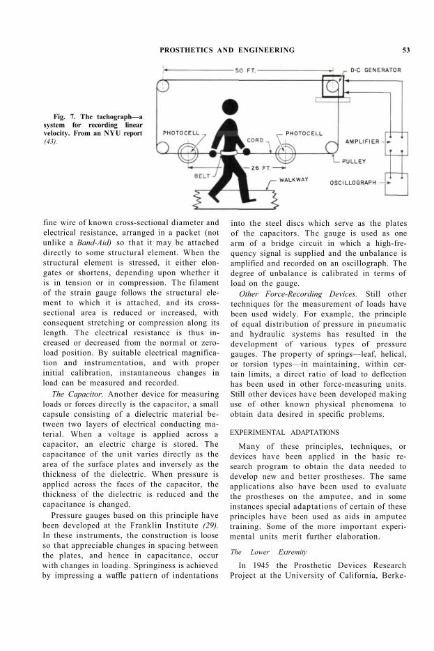
in limited space, the interrupted-light method cannot readily be employed, for the pattern of points cannot then be distinguished as to occurrence in time. To overcome this difficulty, Bernshtein (7) in Russia and Drillis (15) in Latvia developed the gliding cyclogram. This method is similar to that previously described except that here the film is transported across the field at a constant rate but at one that may be varied to suit the particular activity being recorded. Under these circumstances, the position of any point can be identified both in space and time. Even if, in a repetitive motion, a point on a moving segment is returned to an original position, the image in the initial and succeeding instances will be displaced on the film by the distance the film has been transported in the elapsed time increment. If, for example, a point were moving in a circular path, its locus would appear on the film as a cycloid. Although this method increases the amount of work to be done in data reduction, 3 suitable graphic shortcuts reduce this work differential to a minimum. As will be apparent (Fig. 6), the gliding cyclogram has special advantages in recording the motion of arm activities, many of which are repetitive and overlapping.
3 Since a constant value—the distance the film is transported in an increment of time—must always be subtracted from the measured horizontal displacement of a point.
The Tachograph Although each of these methods permits the
measurement of displacement, velocity, and acceleration, other methods of instrumentation
PROSTHETICS AND ENGINEERING 51
give direct measurement of velocity and acceleration in certain situations. Velocities along one axis may be measured with a tachograph, a device consisting of a fine cable connected to a moving body, continuing in a closed loop, and driving the rotor of a generator (Fig. 7). Since the voltage is proportional to the angular velocity of the rotor, which in turn is proportional to the velocity of the body, the voltage generated is a direct measure of the linear velocity.
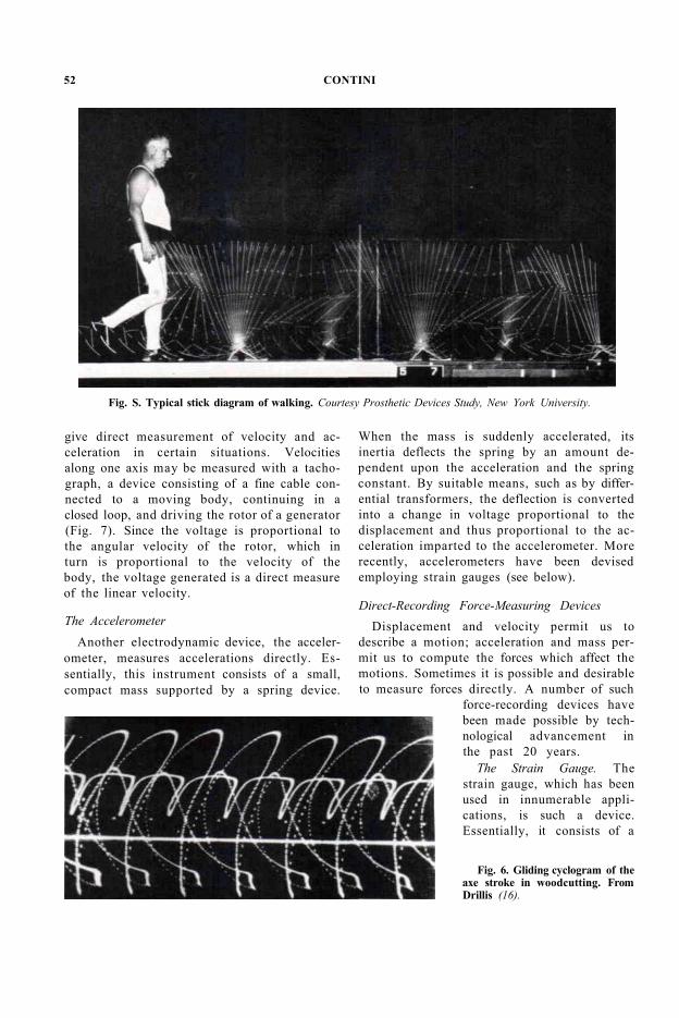
Fig. S. Typical stick diagram of walking. Courtesy Prosthetic Devices Study, New York University.
Fig. 6. Gliding cyclogram of the axe stroke in woodcutting. From Drillis (16).
The Accelerometer Another electrodynamic device, the acceler
ometer, measures accelerations directly. Essentially, this instrument consists of a small, compact mass supported by a spring device.
When the mass is suddenly accelerated, its inertia deflects the spring by an amount dependent upon the acceleration and the spring constant. By suitable means, such as by differential transformers, the deflection is converted into a change in voltage proportional to the displacement and thus proportional to the acceleration imparted to the accelerometer. More recently, accelerometers have been devised employing strain gauges (see below).
Direct-Recording Force-Measuring Devices Displacement and velocity permit us to
describe a motion; acceleration and mass permit us to compute the forces which affect the motions. Sometimes it is possible and desirable to measure forces directly. A number of such
force-recording devices have been made possible by technological advancement in the past 20 years.
The Strain Gauge. The strain gauge, which has been used in innumerable applications, is such a device. Essentially, it consists of a
52 CONTINI
fine wire of known cross-sectional diameter and electrical resistance, arranged in a packet (not unlike a Band-Aid) so that it may be attached directly to some structural element. When the structural element is stressed, it either elongates or shortens, depending upon whether it is in tension or in compression. The filament of the strain gauge follows the structural element to which it is attached, and its cross-sectional area is reduced or increased, with consequent stretching or compression along its length. The electrical resistance is thus increased or decreased from the normal or zero-load position. By suitable electrical magnification and instrumentation, and with proper initial calibration, instantaneous changes in load can be measured and recorded.
The Capacitor. Another device for measuring loads or forces directly is the capacitor, a small capsule consisting of a dielectric material between two layers of electrical conducting material. When a voltage is applied across a capacitor, an electric charge is stored. The capacitance of the unit varies directly as the area of the surface plates and inversely as the thickness of the dielectric. When pressure is applied across the faces of the capacitor, the thickness of the dielectric is reduced and the capacitance is changed.
Pressure gauges based on this principle have been developed at the Franklin Institute (29). In these instruments, the construction is loose so that appreciable changes in spacing between the plates, and hence in capacitance, occur with changes in loading. Springiness is achieved by impressing a waffle pattern of indentations
into the steel discs which serve as the plates of the capacitors. The gauge is used as one arm of a bridge circuit in which a high-frequency signal is supplied and the unbalance is amplified and recorded on an oscillograph. The degree of unbalance is calibrated in terms of load on the gauge.
Other Force-Recording Devices. Still other techniques for the measurement of loads have been used widely. For example, the principle of equal distribution of pressure in pneumatic and hydraulic systems has resulted in the development of various types of pressure gauges. The property of springs—leaf, helical, or torsion types—in maintaining, within certain limits, a direct ratio of load to deflection has been used in other force-measuring units. Still other devices have been developed making use of other known physical phenomena to obtain data desired in specific problems.
Fig. 7. The tachograph—a system for recording linear velocity. From an NYU report (43).
EXPERIMENTAL ADAPTATIONS
Many of these principles, techniques, or devices have been applied in the basic research program to obtain the data needed to develop new and better prostheses. The same applications also have been used to evaluate the prostheses on the amputee, and in some instances special adaptations of certain of these principles have been used as aids in amputee training. Some of the more important experimental units merit further elaboration.
The Lower Extremity
In 1945 the Prosthetic Devices Research Project at the University of California, Berke-
PROSTHETICS AND ENGINEERING 53

ley, initiated a program of basic research directed toward the gathering of information on locomotion, both in normal subjects and in leg amputees. It was desired to obtain data on the individual factors which contribute to the pattern of human gait—the displacements of the head, arms, and torso; the displacements and rates of displacement of the thigh, shank, and foot; the moments at the hip, knee, and ankle joints; the pressure at the point of ground contact; and the shift in apparent point of pressure application. Using the techniques already described, the engineers participating in this program developed a variety of ingenious devices (18,56).
To record the displacements of the segments of the body, motion-picture techniques were adopted. The appropriate control points on the body were identified by targets, in some instances the motions of small magnitude were magnified by target extensions, and in other instances the pattern of locomotion was photographed at intervals varying up to 3000 per second. To obtain the components of motion along the three axes of space, a glass walkway and tilted mirror were used. By this expedient, side and plan pictures were taken simultaneously on one film, thus minimizing the time required for reduction of data and also reducing the possibility of error as compared to the use of two synchronized cameras. From these photographs the motions of the leg segments, heel and toe rise, degree of knee flexion, phasing of the step, and all other desired details could be analyzed. Forces during the swing phase could be determined, as could also the moments at the joints.
To measure ground reaction, two force plates were designed using strain gauges in various combinations to measure vertical, fore-and-aft, and lateral components of foot pressure at ground contact. Through appropriate electronic combinations, the strain pickup also could give the apparent instantaneous center of pressure and the torsional moments exerted by the rotation of the foot at ground contact. In a similar study conducted by the Research Division, College of Engineering, New York University, the same elements, strain gauges, and structural beams were combined in another variation of the force plate (42). Both the UC
and the NYU force plates represented a refinement of those conceived and used by Elftman (20), who, in his earlier studies in human locomotion, had used springs and dial gauges to record components of forces.
The Upper Extremity
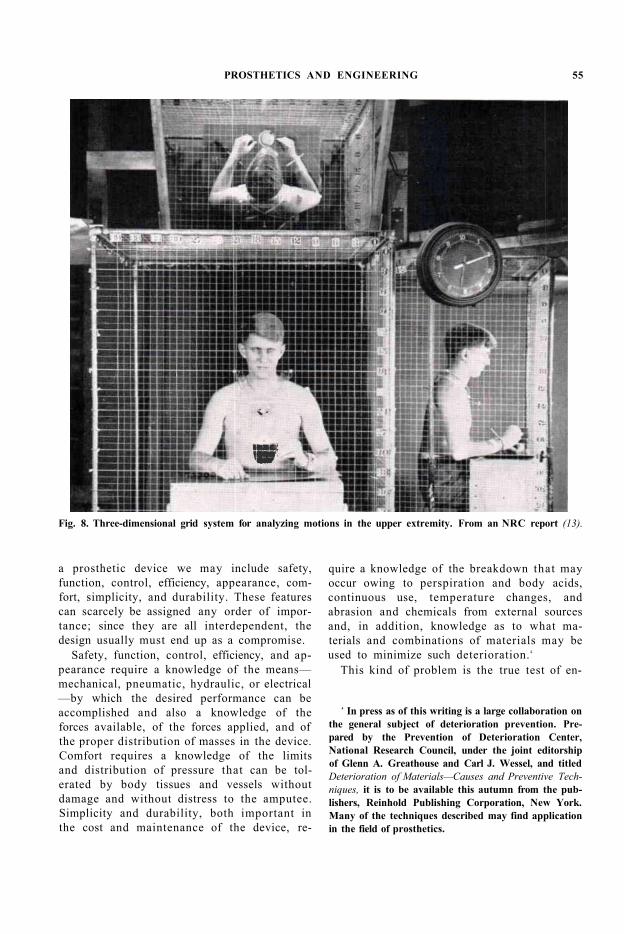
The University of California at Los Angeles, through its Engineering School, was entrusted with basic research in the upper extremity. To study the range of movement required by arm prostheses in the performance of selected daily activities, a photographic procedure was established. A subject was placed within an enclosure composed of vertical, horizontal, and lateral grids. Two mirrors permitted views in the horizontal and lateral planes (Fig. 8). When the subject was photographed, the motion of the targets on the joints could be pictured simultaneously in all three planes, together with the coordinate grids, thus permitting rapid data reduction. An ingenious mannikin enabled the duplication of motions photographed for further study of particular combinations of angular displacement of segments.
Adaptations to Evaluation
It is difficult to indicate clear boundaries between the basic research and the evaluation stages in the Artificial Limb Program, for many of the tools used to obtain basic data also are useful to the group at New York University engaged in the evaluation of prostheses. These techniques and others now being used in the evaluation program are discussed later (page 65). As the measuring and recording instruments become more generally applied, scientists other than engineers will become equally proficient in their use. When the need arises, the engineering profession undoubtedly will produce even more refined devices for measuring more complex performances.
PROSTHETICS DESIGN
Important as is the role of engineering in the development of instrumentation and equipment for basic research in human motion, it is in the second stage of any prosthetics program—the design of the prosthetic device— that the engineer is pre-eminent. Among the many factors he must consider in the design of
54 CONTINI
a prosthetic device we may include safety, function, control, efficiency, appearance, comfort, simplicity, and durability. These features can scarcely be assigned any order of importance; since they are all interdependent, the design usually must end up as a compromise.
Safety, function, control, efficiency, and appearance require a knowledge of the means— mechanical, pneumatic, hydraulic, or electrical —by which the desired performance can be accomplished and also a knowledge of the forces available, of the forces applied, and of the proper distribution of masses in the device. Comfort requires a knowledge of the limits and distribution of pressure that can be tolerated by body tissues and vessels without damage and without distress to the amputee. Simplicity and durability, both important in the cost and maintenance of the device, re
quire a knowledge of the breakdown that may occur owing to perspiration and body acids, continuous use, temperature changes, and abrasion and chemicals from external sources and, in addition, knowledge as to what materials and combinations of materials may be used to minimize such deterioration. 4
4 In press as of this writing is a large collaboration on the general subject of deterioration prevention. Prepared by the Prevention of Deterioration Center, National Research Council, under the joint editorship of Glenn A. Greathouse and Carl J. Wessel, and titled Deterioration of Materials—Causes and Preventive Techniques, it is to be available this autumn from the publishers, Reinhold Publishing Corporation, New York. Many of the techniques described may find application in the field of prosthetics.
Fig. 8. Three-dimensional grid system for analyzing motions in the upper extremity. From an NRC report (13).
This kind of problem is the true test of en-
PROSTHETICS AND ENGINEERING 55
gineering. All the physical sciences which contribute to the substance of engineering may be called upon in evolving the final product. The mechanical engineer contributes his knowledge of mechanisms—cams and gears and linkages, which together may reproduce a motion. With the hydraulic and electrical engineer, he devises means for the operation or control of the prosthesis, for damping a swing, or for magnifying the power available within the amputee. The metallurgical engineer develops the alloys which go into the joints and prescribes methods of treatment to bring out the maximum qualities desired—strength or ductility or resilience or wear. The chemical engineer makes available the new synthetic substances which so handsomely replace the natural substances heretofore the only materials available. Plastics, whether they be the strong, structural resins used in the lamination of shanks and arms (11,44), or whether they be the plastics used for cosmetic purposes (36), have radically changed the appearance, weight, and sanitary properties of prostheses.
The design engineer must combine all this knowledge into the most effective whole. He must bring to the job all of the experience and ingenuity he possesses so that the ultimate product will not only produce the desired function, be strong enough, and last an adequate period but will also be relatively inexpensive and simple enough to be maintained locally with a minimum of special tools. The making of artificial limbs can now be based on well-established scientific principles; it can cease to be empirical and can become a branch of engineering and medical activity. But without the necessary technical skills, progress in prostheses will return to the trial-and-error system from which it has so recently emerged. Some of the specific problems to be solved, and the methods for their solution, which have occurred in the design of upper- and lower-extremity prostheses, deserve to be discussed in some detail.
THE LOWER EXTREMITY
The scientific basis for lower-extremity prostheses is provided by biomechanical investigation of the functions of the lower limb in human locomotion. Man is an erect biped,
that is, he has two supporting limbs and the mass of his body is carried in a vertical plane. The human body, then, may be represented as an upper mass upheld by two supporting columns. The upper mass consists of the head, arms, and trunk. The supporting columns are the two lower limbs. Of complex character, they each consist of three segments, superposed and movable on each other. To meet the needs of standing, the three movable segments form a quasi-rigid column by virtue of their superposition.
The standing position includes standing on both feet and standing on one foot, as in the stance phase during locomotion when the weight is borne on one foot only. The vertical line passing through the center of gravity of the body passes behind the line connecting the centers of the two hip joints and in front of the axes of the knee joints. Extension of the trunk relative to the thigh and of the thigh relative to the shank is thus maintained by gravity and limited by powerful ligaments. The two lower limbs therefore remain rigid with a minimum use of active muscle groups. But locomotion demands that the lower limbs be composed of movable, superposed segments. This requirement appears irreconcilable with the demands imposed by the standing position, but the natural arrangement of the lower limbs meets both requirements. Mobility of the hip and knee joints is essential in performing a normal step, a motion which can be divided into four alternating phases, two phases of support on both feet and two phases on each foot alternately.
During single support on one foot, the supporting leg bears the weight of the body while the other swings in the sagittal plane like a pendulum suspended from the trunk. Since the two lower limbs are of precisely the same length, the swinging leg must become shorter than the supporting one, or else the swinging foot would drag on the ground. Shortening of the swing leg is effected by flexion of the thigh on the trunk, of the shank on the thigh, and of the foot on the shank.
The geometry of the hip joint, and particularly that of the knee and ankle joints, is very complex. Not all authorities are in agreement as to the movements of the segments of the
56 CONTINI
lower limb in flexion and extension, but enough is known to provide information as to how stability and mobility are provided both in standing and in walking. In the manufacture of artificial legs, it is desirable to reproduce insofar as possible the static and dynamic characteristics of the sound limb.
The Above-Knee Case With notably rare exceptions, the design of
artificial legs proceeded along a fairly well-defined pattern. Generally, until the middle of the nineteenth century, and now still so in many underprivileged countries, it was considered adequate to supply the leg amputee with a peg-leg. For above-knee amputations, it consisted of a pylon supported below a pad, corset, or socket, which in some fashion was attached to the stump or suspended from the shoulders. For below-knee amputees, the stump was flexed and the peg-leg attached below the flexed knee.
Such an artificial leg satisfied completely one of the two functions of the normal leg. It provided a column which, together with the sound leg, allowed the individual to stand erect. It also enabled the wearer to walk, although, since there was no knee joint, it affected the amputee's gait considerably. In the swing phase, the wearer was required to raise the hip on the amputated side in order to swing through; in the stance phase he necessarily had to vault over the pylon. Although such a device is simple, strong, inexpensive, and quite serviceable, the amputee is subjected to excessive stress during walking, his gait is asymmetric and unnatural, his performance in walking is inefficient, and his physical appearance is far from cosmetic.
Next in order of development was the so-called "conventional" leg (Fig. 6, page 11). In general, this prosthesis was made to look like the sound leg, that is, it possessed some cosmetic appearance. The knee was hinged and could be flexed, although in the earlier devices a knee lock was provided to assure stability in standing. The foot was attached to the shank with either a rigid or a jointed ankle.
This order of devices had many advantages over the peg-leg, but it introduced other problems. Because of the knee hinge, it was pos
sible to sit or kneel or to perform in a more natural manner other activities requiring knee flexion. Moreover, because of the knee joint, when not provided with a knee lock, the amputee was able to walk with a better gait. Knee flexion permitted a certain amount of leg shortening in the swing phase, thus reducing the amount of hip elevation required to clear the ground. But the knee and ankle joints introduced instability in the stance phase, particularly at heel contact. The free-swinging leg resulted in an exaggerated back swing and forward swing with a pronounced shock at each stop. Later compromises were effected by setting the knee bolt forward of the weight line of the body, by addition of check straps to decelerate the shank at toe-ofi and to provide some assistance at the beginning of the forward swing, by introducing friction devices at the knee bolt, by a combination of both, and by limiting ankle motion through the use of bumper blocks.
With minor and individual exceptions, this was the general state of development at which the above-knee prosthesis had remained until the end of World War I I . As a result of the research initiated thereafter, engineers began to devote time to the application of old and new knowledge to the design of lower-extremity prostheses. Among the features which had been demonstrated as desirable were flexion at the knee but with some stabilizing control at the time of heel contact and immediately thereafter, some measure of support in an emergency situation such as in stubbing the toe, a controlled swing of the leg, an ankle joint which would permit rotation in a horizontal plane as well as in the sagittal and transverse planes and yet not be so flexible as to increase instability, and a toe-lift device for ground clearance in the swing phase. All this was to be accomplished without substantially increasing weight, sacrificing durability, or increasing initial and maintenance costs of the device. By combining known engineering principles with newly developed materials, a substantial gain was achieved in the above-knee prosthesis, with consequent improvement in the performance of many leg amputees.
The U.S. Navy above-knee leg (12,57,58) developed at the U.S. Naval Hospital, Oak-
PROSTHETICS AND ENGINEERING 57
land, California, is an example of such an improved prosthesis. Controlled swing with terminal deceleration was achieved by the use of friction devices which come into operation in the last portion only of the forward and backward swings. New plastics and molding techniques provide a much more natural appearance. New methods of bonding rubber and a new method of attaching the foot to the shank allow for greater flexibility at the ankle without serious problems of instability.
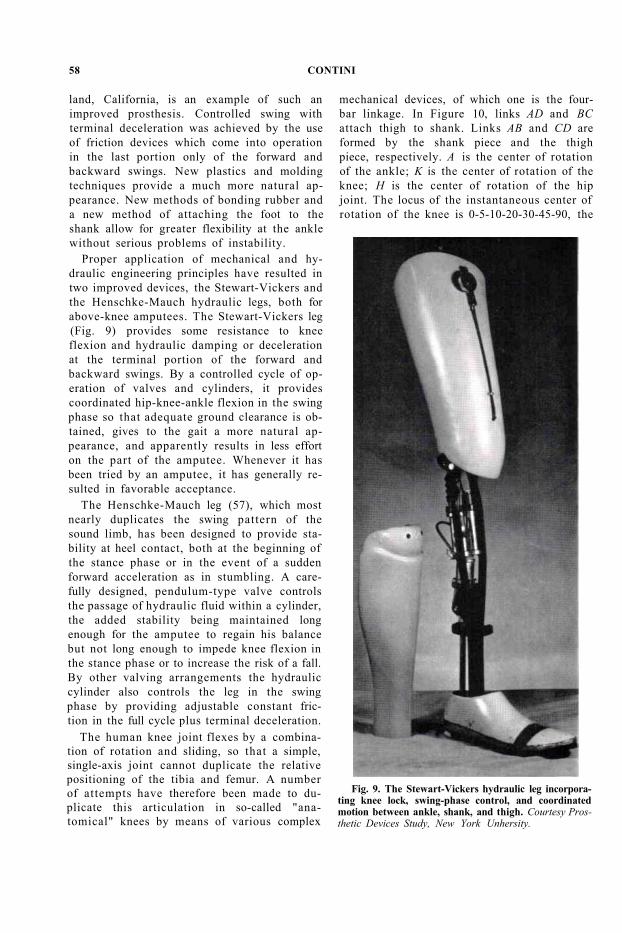
Proper application of mechanical and hydraulic engineering principles have resulted in two improved devices, the Stewart-Vickers and the Henschke-Mauch hydraulic legs, both for above-knee amputees. The Stewart-Vickers leg (Fig. 9) provides some resistance to knee flexion and hydraulic damping or deceleration at the terminal portion of the forward and backward swings. By a controlled cycle of operation of valves and cylinders, it provides coordinated hip-knee-ankle flexion in the swing phase so that adequate ground clearance is obtained, gives to the gait a more natural appearance, and apparently results in less effort on the part of the amputee. Whenever it has been tried by an amputee, it has generally resulted in favorable acceptance.
The Henschke-Mauch leg (57), which most nearly duplicates the swing pattern of the sound limb, has been designed to provide stability at heel contact, both at the beginning of the stance phase or in the event of a sudden forward acceleration as in stumbling. A carefully designed, pendulum-type valve controls the passage of hydraulic fluid within a cylinder, the added stability being maintained long enough for the amputee to regain his balance but not long enough to impede knee flexion in the stance phase or to increase the risk of a fall. By other valving arrangements the hydraulic cylinder also controls the leg in the swing phase by providing adjustable constant friction in the full cycle plus terminal deceleration.
Fig. 9. The Stewart-Vickers hydraulic leg incorporating knee lock, swing-phase control, and coordinated motion between ankle, shank, and thigh. Courtesy Prosthetic Devices Study, New York Unhersity.
The human knee joint flexes by a combination of rotation and sliding, so that a simple, single-axis joint cannot duplicate the relative positioning of the tibia and femur. A number of attempts have therefore been made to duplicate this articulation in so-called "anatomical" knees by means of various complex
mechanical devices, of which one is the four-bar linkage. In Figure 10, links AD and BC attach thigh to shank. Links AB and CD are formed by the shank piece and the thigh piece, respectively. A is the center of rotation of the ankle; K is the center of rotation of the knee; H is the center of rotation of the hip joint. The locus of the instantaneous center of rotation of the knee is 0-5-10-20-30-45-90, the
58 CONTINI
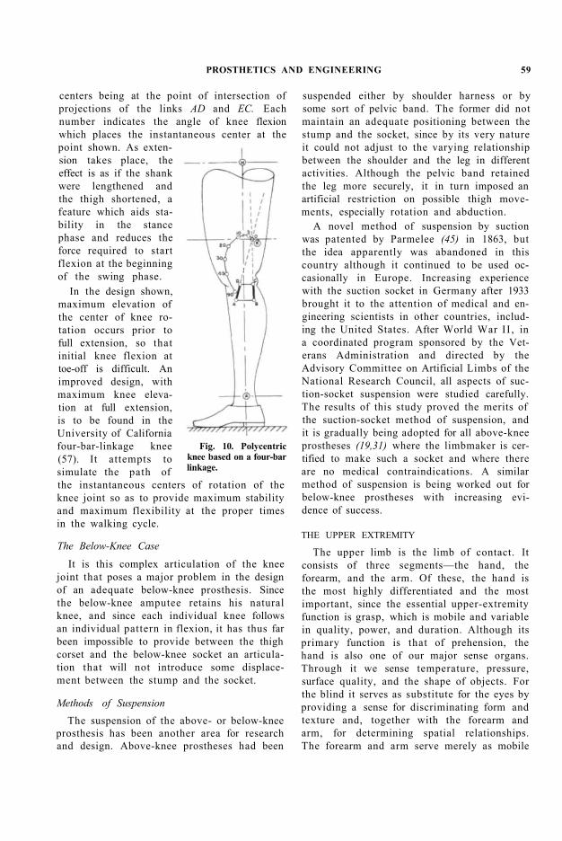
centers being at the point of intersection of projections of the links AD and EC. Each number indicates the angle of knee flexion which places the instantaneous center at the point shown. As extension takes place, the effect is as if the shank were lengthened and the thigh shortened, a feature which aids stability in the stance phase and reduces the force required to start flexion at the beginning of the swing phase.
In the design shown, maximum elevation of the center of knee rotation occurs prior to full extension, so that initial knee flexion at toe-off is difficult. An improved design, with maximum knee elevation at full extension, is to be found in the University of California four-bar-linkage knee (57). It attempts to simulate the path of the instantaneous centers of rotation of the knee joint so as to provide maximum stability and maximum flexibility at the proper times in the walking cycle.
Fig. 10. Polycentric knee based on a four-bar linkage.
The Below-Knee Case
It is this complex articulation of the knee joint that poses a major problem in the design of an adequate below-knee prosthesis. Since the below-knee amputee retains his natural knee, and since each individual knee follows an individual pattern in flexion, it has thus far been impossible to provide between the thigh corset and the below-knee socket an articulation that will not introduce some displacement between the stump and the socket.
Methods of Suspension The suspension of the above- or below-knee
prosthesis has been another area for research and design. Above-knee prostheses had been
suspended either by shoulder harness or by some sort of pelvic band. The former did not maintain an adequate positioning between the stump and the socket, since by its very nature it could not adjust to the varying relationship between the shoulder and the leg in different activities. Although the pelvic band retained the leg more securely, it in turn imposed an artificial restriction on possible thigh movements, especially rotation and abduction.
A novel method of suspension by suction was patented by Parmelee (45) in 1863, but the idea apparently was abandoned in this country although it continued to be used occasionally in Europe. Increasing experience with the suction socket in Germany after 1933 brought it to the attention of medical and engineering scientists in other countries, including the United States. After World War II , in a coordinated program sponsored by the Veterans Administration and directed by the Advisory Committee on Artificial Limbs of the National Research Council, all aspects of suction-socket suspension were studied carefully. The results of this study proved the merits of the suction-socket method of suspension, and it is gradually being adopted for all above-knee prostheses (19,31) where the limbmaker is certified to make such a socket and where there are no medical contraindications. A similar method of suspension is being worked out for below-knee prostheses with increasing evidence of success.
THE UPPER EXTREMITY
The upper limb is the limb of contact. It consists of three segments—the hand, the forearm, and the arm. Of these, the hand is the most highly differentiated and the most important, since the essential upper-extremity function is grasp, which is mobile and variable in quality, power, and duration. Although its primary function is that of prehension, the hand is also one of our major sense organs. Through it we sense temperature, pressure, surface quality, and the shape of objects. For the blind it serves as substitute for the eyes by providing a sense for discriminating form and texture and, together with the forearm and arm, for determining spatial relationships. The forearm and arm serve merely as mobile
PROSTHETICS AND ENGINEERING 59
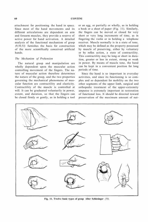
attachment for positioning the hand in space. Since most of the hand movements and its different articulations are dependent on arm and forearm muscles, they provide a reserve of active power for hand activation. A detailed analysis of the functional mechanism of grasp (9,50,53) furnishes the basis for construction of the more scientifically conceived artificial hands.
Fig. 11. Twelve basic types of grasp After Schlesinger {50).
The Mechanism of Prehension The natural grasp and manipulation are
wholly dependent upon the muscular action controlling movement of the fingers. The nature of muscular action therefore determines the nature of the grasp, and the two properties governing the mechanical phenomena of muscular function are contractility and elasticity. Contractility of the muscle is controlled at will. It can be graduated voluntarily in power, extent, and duration, so that the fingers can be closed firmly or gently, as in holding a tool
or an egg, or partially or wholly, as in holding a book or a sheet of paper (Fig. 11). Similarly, the fingers can be moved or closed for very short or very long increments of time, as in fingering the violin or in holding a telephone receiver. Muscle normally is in a state of tone, which may be defined as the property possessed by muscle of preserving, either by voluntary or by reflex action, a state of contractility. This contractility may be long or short in duration, greater or less in extent, strong or weak in power. By means of muscle tone, the hand can be kept in a convenient position for long periods of time.
Since the hand is so important in everyday activities, and since its functioning is so complex and so dependent for mobility on the two other segments of the upper limb, surgical and orthopedic treatment of the upper-extremity amputee is extremely important in restoration of functional loss. It should be directed toward preservation of the maximum amount of nat-
60 CONTINI

ural mobility. Since it is not yet possible to create artificial muscle, it is necessary to reproduce as well as possible by indirect processes the effects of normal muscle action on the fingers. Prostheses for this purpose are successful in such proportion as the mechanical effects produced approximate those of the natural limb.
Fig. 12. Below-elbow biceps cineplasty control system.
Substitute Power Sources
Until the present, and even now with all the currently available technology, the most adequate substitutes for the lost muscle activators are muscular substitutes, self-powered agents which induce the movement of the artificial fingers by means of artificial tendons, that is, by control cords. The latter are, as a rule, attached by some appropriate means to the shoulder on the amputated side or on the normal side or both. The movement produced by them is thus entirely dependent upon the shoulder group of muscles. Improvements in surgical techniques (3) and extensive research in muscle physiology (34) recently have reawakened interest in the use of cineplastic procedures to provide other muscle motors (Fig. 12). Both the biceps and pectoral muscle groups have been used for this purpose.
Since the action of the controlling muscles must continue for such periods as required for the particular grasp function concerned, the
muscular substitute can become heavily burdened. It is therefore absolutely necessary to arrange for release of the muscular substitute once the fingers have been placed in the appropriate position. This is achieved by mechanisms which produce in the artificial fingers the same effect as that produced by muscle tone in the natural fingers.
Prior Art in Upper-Extremity Prosthetics
Although the basic concept of an artificial arm and its terminal device has not changed materially from that of the first arms made many years ago, recent technological developments in materials of construction and a better application of known mechanical principles have together resulted in arms of improved appearance and greatly improved function. As in the artificial leg, the materials most commonly used for the artificial arm and forearm have been wood and leather. Control was achieved by shoulder harness operating through control cords, usually leather, connected to the terminal device, which was usually a split hook, that is, a pair of iron or steel fingers bent in the shape of a hook and so hinged as to close on each other. For different applications the shape of the hook was modified as appropriate. Since in general the closed position required for grasping an object is of longer duration than is the open position for
PROSTHETICS AND ENGINEERING 61

approaching the object, opening was effected by the shoulder muscles and closing was brought about by some spring or elastic medium. Cosmetic appearance was neglected or, in those few cases where it was attempted, a passive hand was the usual result.
To return to the arm amputee some measure of productive capacity, there were devised a great many one-function terminal devices, each intended for some particular occupational need (Fig. 13). Such "tools" could be inserted and attached to the distal end of the artificial arm. The practice was predominantly European, and we see in their "armamentaria"
hooks, rings, hammers, knives, brushes, and a multiplicity of other designs intended to enable the amputee to function in his customary occupation as smith or carpenter or metal worker (9,50,54).
Present-day technology and a formal approach to the design of both arms and terminal devices has since effected vast improvements in upper-extremity prostheses. Although most of the newer designs have been described in detail in available literature (26,27,28), it is appropriate here to review these developments in a very general way as they relate to engineering practice.
Fig. 13. Typical occupational-aid terminal devices, all European. The screened boxes indicate the devices recommended for the various activities. From a German report (54).
62 CONTINI
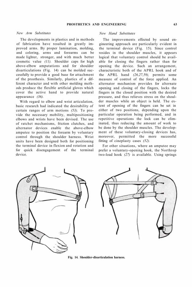
Fig. 14. Shoulder-disarticulation harness.
New Arm Substitutes
The developments in plastics and in methods of fabrication have resulted in greatly improved arms. By proper lamination, molding, and coloring, arms and forearms can be made lighter, stronger, and with much better cosmetic value (11). Shoulder caps for high above-elbow amputations and for shoulder disarticulations (Fig. 14) can be molded successfully to provide a good base for attachment of the prosthesis. Similarly, plastics of a different character and with other molding methods produce the flexible artificial gloves which cover the active hand to provide natural appearance (36).
With regard to elbow and wrist articulation, basic research had indicated the desirability of certain ranges of arm motions (53). To provide the necessary mobility, multipositioning elbows and wrists have been devised. The use of ratchet mechanisms, friction clutches, and alternator devices enable the above-elbow amputee to position the forearm by voluntary control through the shoulder harness. Wrist units have been designed both for positioning the terminal device in flexion and rotation and for quick disengagement of the terminal device.
New Hand Substitutes
The improvements effected by sound engineering approach are particularly evident in the terminal device (Fig. 15). Since control resides in the shoulder muscles, it appears logical that voluntary control should be available for closing the fingers rather than for opening the device. Such an arrangement, characteristic both of the APRL hook and of the APRL hand (26,27,59), permits some measure of control of the force applied. An alternator mechanism provides for alternate opening and closing of the fingers, locks the fingers in the closed position with the desired pressure, and thus relieves stress on the shoulder muscles while an object is held. The extent of opening of the fingers can be set in either of two positions, depending upon the particular operation being performed, and in repetitive operations the lock can be eliminated, thus reducing the amount of work to be done by the shoulder muscles. The development of these voluntary-closing devices has, moreover, permitted the more successful fitting of cineplasty cases (52).
For other situations, where an amputee may prefer a voluntary-opening hook, the Northrop two-load hook (27) is available. Using springs
PROSTHETICS AND ENGINEERING 63
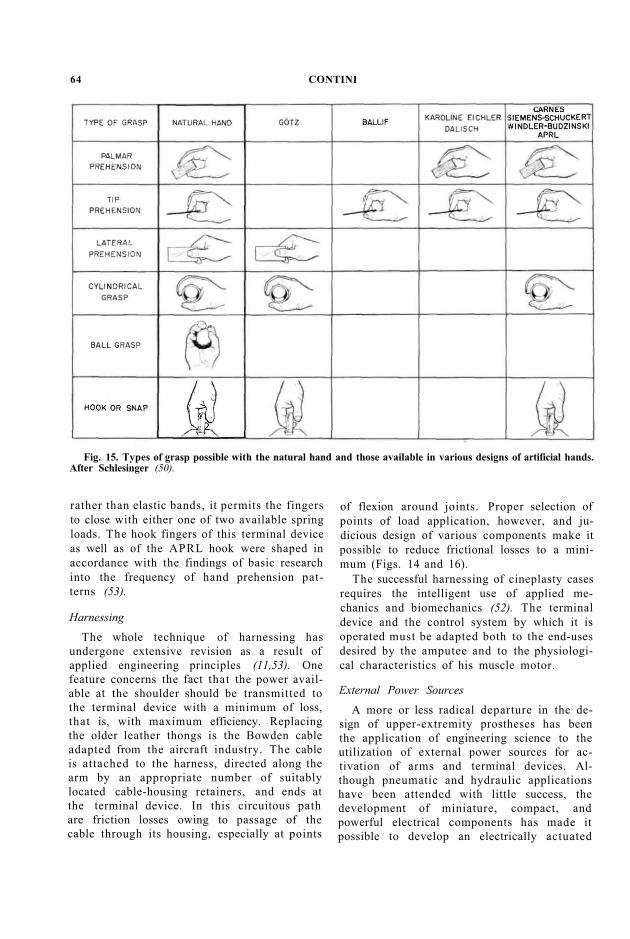
rather than elastic bands, it permits the fingers to close with either one of two available spring loads. The hook fingers of this terminal device as well as of the APRL hook were shaped in accordance with the findings of basic research into the frequency of hand prehension patterns (53).
Fig. 15. Types of grasp possible with the natural hand and those available in various designs of artificial hands. After Schlesinger (50).
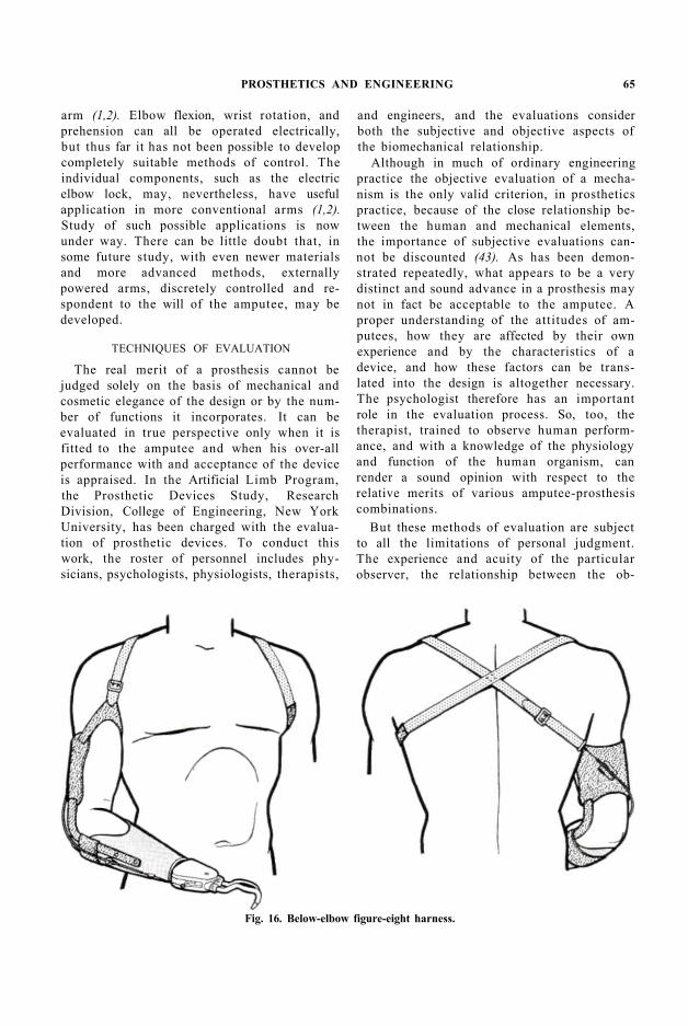
Harnessing The whole technique of harnessing has
undergone extensive revision as a result of applied engineering principles (11,53). One feature concerns the fact that the power available at the shoulder should be transmitted to the terminal device with a minimum of loss, that is, with maximum efficiency. Replacing the older leather thongs is the Bowden cable adapted from the aircraft industry. The cable is attached to the harness, directed along the arm by an appropriate number of suitably located cable-housing retainers, and ends at the terminal device. In this circuitous path are friction losses owing to passage of the cable through its housing, especially at points
of flexion around joints. Proper selection of points of load application, however, and judicious design of various components make it possible to reduce frictional losses to a minimum (Figs. 14 and 16).
The successful harnessing of cineplasty cases requires the intelligent use of applied mechanics and biomechanics (52). The terminal device and the control system by which it is operated must be adapted both to the end-uses desired by the amputee and to the physiological characteristics of his muscle motor.
External Power Sources A more or less radical departure in the de
sign of upper-extremity prostheses has been the application of engineering science to the utilization of external power sources for activation of arms and terminal devices. Although pneumatic and hydraulic applications have been attended with little success, the development of miniature, compact, and powerful electrical components has made it possible to develop an electrically actuated
64 CONTINI
arm (1,2). Elbow flexion, wrist rotation, and prehension can all be operated electrically, but thus far it has not been possible to develop completely suitable methods of control. The individual components, such as the electric elbow lock, may, nevertheless, have useful application in more conventional arms (1,2). Study of such possible applications is now under way. There can be little doubt that, in some future study, with even newer materials and more advanced methods, externally powered arms, discretely controlled and respondent to the will of the amputee, may be developed.
Fig. 16. Below-elbow figure-eight harness.
TECHNIQUES OF EVALUATION
The real merit of a prosthesis cannot be judged solely on the basis of mechanical and cosmetic elegance of the design or by the number of functions it incorporates. It can be evaluated in true perspective only when it is fitted to the amputee and when his over-all performance with and acceptance of the device is appraised. In the Artificial Limb Program, the Prosthetic Devices Study, Research Division, College of Engineering, New York University, has been charged with the evaluation of prosthetic devices. To conduct this work, the roster of personnel includes physicians, psychologists, physiologists, therapists,
and engineers, and the evaluations consider both the subjective and objective aspects of the biomechanical relationship.
Although in much of ordinary engineering practice the objective evaluation of a mechanism is the only valid criterion, in prosthetics practice, because of the close relationship between the human and mechanical elements, the importance of subjective evaluations cannot be discounted (43). As has been demonstrated repeatedly, what appears to be a very distinct and sound advance in a prosthesis may not in fact be acceptable to the amputee. A proper understanding of the attitudes of amputees, how they are affected by their own experience and by the characteristics of a device, and how these factors can be translated into the design is altogether necessary. The psychologist therefore has an important role in the evaluation process. So, too, the therapist, trained to observe human performance, and with a knowledge of the physiology and function of the human organism, can render a sound opinion with respect to the relative merits of various amputee-prosthesis combinations.
But these methods of evaluation are subject to all the limitations of personal judgment. The experience and acuity of the particular observer, the relationship between the ob-
PROSTHETICS AND ENGINEERING 65
server and the amputee, and other individual factors will in some way affect the evaluation. To a certain extent these variables are controlled by a comparison and correlation of judgments of different observers, but even under the most favorable conditions there may always be areas of disagreement as to what has been observed.
When positive criteria of performance with a prosthetic device can be established, it becomes very important to be able to measure and record accurately those factors which constitute the criteria. Instrumentation and methods developed on the basis of engineering knowledge provide the tools for obtaining objective data. They enable the investigator to compare the performance of a particular amputee with different prostheses, of a given amputee with the same prosthesis at different times, or of different amputees wearing identical prostheses. The recording instruments and techniques available can record more rapidly, more accurately, and more permanently than can any human observer. All the devices useful in the basic research program are equally useful in the evaluation program.
THE LOWER EXTREMITY
Symmetry in the Walking Pattern
In establishing criteria for the evaluation of lower-extremity prostheses, it has been postulated that the pattern of normal locomotion is symmetrical and, therefore, that the behavior of the normal side may be the legitimate measure of performance of the affected side. That is to say, the more nearly the amputee achieves a symmetrical pattern of locomotion the better the prosthetic device and the better the adjustment to it. Further, it is assumed that, in the performance of activity, the human organism adjusts itself to perform at a minimal level of stress. The measure of performance of normals, then, can be a guide to the relative merits of amputee-prosthesis combinations. Such criteria as stability in the
erect position, variability of stride time, and other biomechanical factors may be used as indices of performance. Lacking proper instrumentation, no objective evaluations of this character could be made.
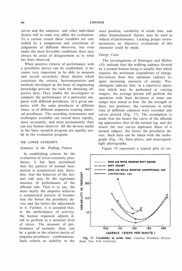
Fig. 17. Variability in stride time. Courtesy Prosthetic Devices Study, New York University.
Energy Costs
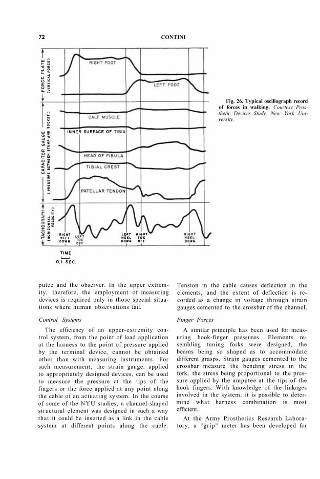
The investigations of Hettinger and Miilier (33) indicate that the walking cadence favored by a normal human being is usually that which requires the minimum expenditure of energy. Deviations from this optimum cadence require increasing amounts of energy. Psychologists indicate that, in a repetitive operation which may be performed at varying tempos, the average person will perform the operation with least deviation at some one tempo best suited to him. On the strength of these two premises, the variations in stride time at different cadences were recorded and curves plotted (Fig. 17). The assumption is made that the nearer the curve of the affected leg approaches that of the normal leg, and the nearer the two curves approach those of a normal subject, the better the prosthetic device. Such data can be taken with the tachograph (Fig. 18), force plates, and interrupted-light photography.
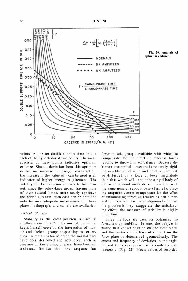
Figure 19 represents a typical plot of ver-
66 CONTINI
tical load versus time during ground contact from heel contact to toe push-off. By means of stick diagrams and force-plate records, this over-all curve may be resolved into one for heel-contact impact and another for toe push-off momentum. When the separation is correct, the area C should be equal to the area D. Used in conjunction with other criteria, these curves give useful information regarding the effect of a prosthesis on the amputee's gait.
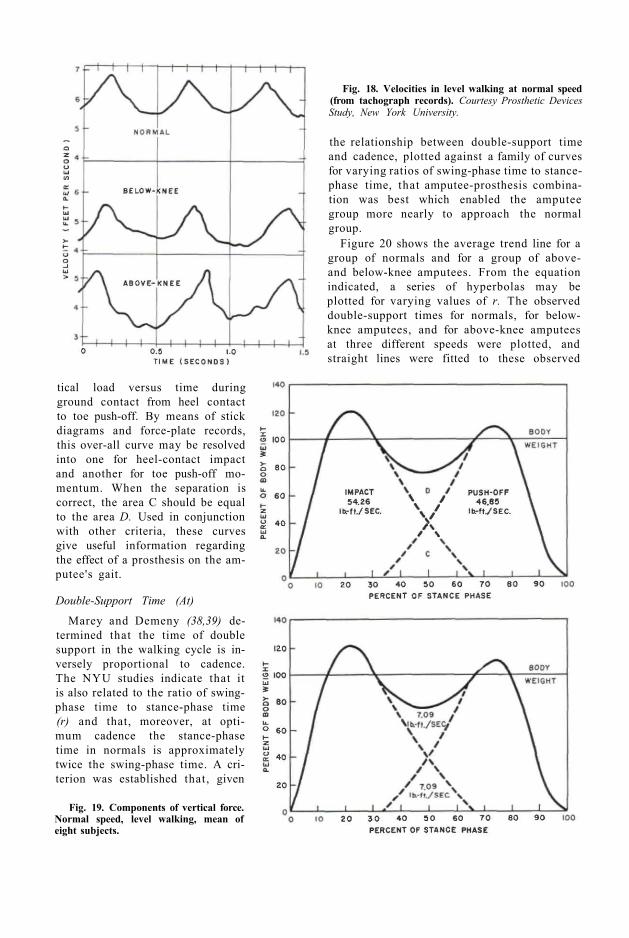
Fig. 18. Velocities in level walking at normal speed (from tachograph records). Courtesy Prosthetic Devices Study, New York University.
Fig. 19. Components of vertical force. Normal speed, level walking, mean of eight subjects.
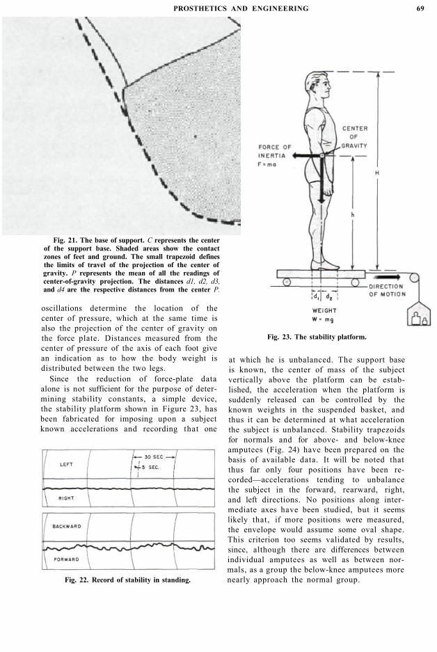
Double-Support Time (At)
Marey and Demeny (38,39) determined that the time of double support in the walking cycle is inversely proportional to cadence. The NYU studies indicate that it is also related to the ratio of swing-phase time to stance-phase time (r) and that, moreover, at optimum cadence the stance-phase time in normals is approximately twice the swing-phase time. A criterion was established that, given
the relationship between double-support time and cadence, plotted against a family of curves for varying ratios of swing-phase time to stance-phase time, that amputee-prosthesis combination was best which enabled the amputee group more nearly to approach the normal group.
Figure 20 shows the average trend line for a group of normals and for a group of above-and below-knee amputees. From the equation indicated, a series of hyperbolas may be plotted for varying values of r. The observed double-support times for normals, for below-knee amputees, and for above-knee amputees at three different speeds were plotted, and straight lines were fitted to these observed
points. A line for double-support time crosses each of the hyperbolas at two points. The mean abscissa of these points indicates optimum cadence. Since a deviation from this optimum causes an increase in energy consumption, the increase in the value of r can be used as an indicator of higher energy requirement. The validity of this criterion appears to be borne out, since the below-knee group, having more of their natural limbs, more nearly approach the normals. Again, such data can be obtained only because adequate instrumentation, force plates, tachograph, and camera are available.
Fig. 20. Analysis of optimum cadence.
Vertical Stability Stability in the erect position is used as
another criterion (17). The normal individual keeps himself erect by the interaction of muscle and skeletal groups responding to sensory cues. In the amputee some of the normal cues have been destroyed and new ones, such as pressure on the stump, or pain, have been introduced. Besides this, the amputee has
fewer muscle groups available with which to compensate for the effect of external forces tending to throw him off balance. Because the human anatomical structure is not truly rigid, the equilibrium of a normal erect subject will be disturbed by a force of lower magnitude than that which will unbalance a rigid body of the same general mass distribution and with the same general support base (Fig. 21). Since the amputee cannot compensate for the effect of unbalancing forces as readily as can a normal, and since in fact poor alignment or fit of the prosthesis may exaggerate the unbalancing effect, the measure of stability is highly important.
Three methods are used for obtaining information on stability. In one, the subject is placed in a known position on one force plate, and the center of the base of support on the force plate is determined geometrically. The extent and frequency of deviation in the sagittal and transverse planes are recorded simultaneously (Fig. 22). Mean values of recorded
68 CONTINI
oscillations determine the location of the center of pressure, which at the same time is also the projection of the center of gravity on the force plate. Distances measured from the center of pressure of the axis of each foot give an indication as to how the body weight is distributed between the two legs.
Since the reduction of force-plate data alone is not sufficient for the purpose of determining stability constants, a simple device, the stability platform shown in Figure 23, has been fabricated for imposing upon a subject known accelerations and recording that one
at which he is unbalanced. The support base is known, the center of mass of the subject vertically above the platform can be established, the acceleration when the platform is suddenly released can be controlled by the known weights in the suspended basket, and thus it can be determined at what acceleration the subject is unbalanced. Stability trapezoids for normals and for above- and below-knee amputees (Fig. 24) have been prepared on the basis of available data. It will be noted that thus far only four positions have been recorded—accelerations tending to unbalance the subject in the forward, rearward, right, and left directions. No positions along intermediate axes have been studied, but it seems likely that, if more positions were measured, the envelope would assume some oval shape. This criterion too seems validated by results, since, although there are differences between individual amputees as well as between normals, as a group the below-knee amputees more nearly approach the normal group.
Fig. 21. The base of support. C represents the center of the support base. Shaded areas show the contact zones of feet and ground. The small trapezoid defines the limits of travel of the projection of the center of gravity. P represents the mean of all the readings of center-of-gravity projection. The distances d1, d2, d3, and d4 are the respective distances from the center P.
Fig. 22. Record of stability in standing.
Fig. 23. The stability platform.
PROSTHETICS AND ENGINEERING 69
relser
Placed Image

Fig. 24. Stability polygon; mean values in percent of g. Courtesy Prosthetic Devices Study, New York University.
Another simple device which has been used to corroborate acceleration data is the inclined platform. A kymograph records the increasing angle of tilt, and the recording is interrupted when the subject topples.
Standardization of Fit and Alignment It is not amiss at this point to mention two
devices, developed at the University of California, which are indispensable in the evaluation procedures. The alignment devices for above- and below-knee prostheses and the transfer jig (47,48) are tools useful in assuring that different prostheses on the same amputee are alike in physical dimensions and positioning, and they make it possible to measure the effects of known changes in position or alignment in the same prosthesis. A third device, developed at the Prosthetic Testing and Development Laboratory of the Veterans Administration, makes it possible to duplicate sockets, a matter of importance when shanks requiring different sockets are needed. The internal contours of the socket can be maintained and their effect on changes in performance thus minimized.
Measurement of Force Distribution Engineering knowledge makes it possible
also to study special characteristics of a device or of a method of fitting. In evaluating the relative merits of the "soft" and hard sockets for below-knee amputees, three new techniques have been evolved. It is desirable to observe changes which occur in the stump as a result of wearing the socket. Accordingly, there has been devised a jig which will hold the amputee in a given position while an impression or cast is made of his stump. Since a rigid pattern of posture is thus imposed, the impression or cast reflects only physiological changes over a period of time. The contours of the stump are then obtained by using a contour tracer or perigraph, also developed for this special purpose. Small variations in contours at known levels can be recorded and compared.
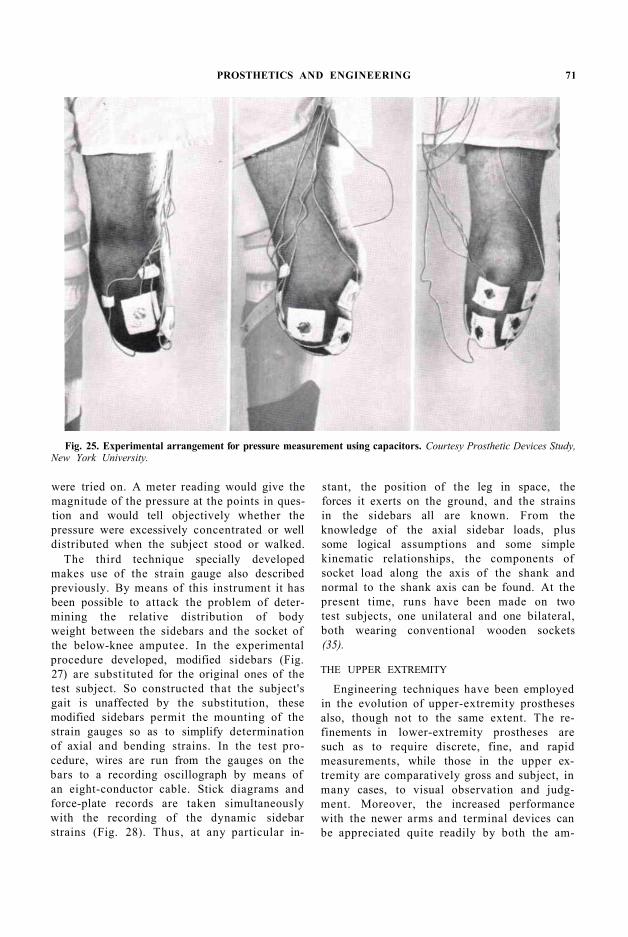
The second technique involves the use of the capacitance gauges previously described. In a study at New York University, in cooperation with the Prosthetic and Sensory Aids Service of the Veterans Administration, they have been applied in an attempt to answer once and for all the question among limb-makers as to the proper distribution of forces within a below-knee socket. Several gauges are attached at points of particular interest on the stump of a below-knee amputee (Fig. 25). The subject then walks at different speeds for a distance of 30 to 40 feet while the unbalance of the gauge bridges is recorded. In this way, simultaneous indications of pressure are obtained at six points on the stump. Although it is still too early to make a general statement, it is evident that great differences exist in the forces exerted by the stump on the socket wall at different points. A composite record of the forces involved during a single stride (Fig. 26) shows the relative magnitudes of forces at a number of points. The maximum observed pressure was 65 lb. per sq. in. at the relatively insensitive patellar tendon. Eventually it is intended to map the total stump contact area for pressure distribution during different phases of the walking cycle.
In addition to the research applications of the pressure gauge, it is likely to find use in the routine fitting of sockets. For this purpose, gauges would be attached to the stump at critical points, such as weight-bearing areas, sore spots, or relieved areas, when a new socket
70 CONTINI
were tried on. A meter reading would give the magnitude of the pressure at the points in question and would tell objectively whether the pressure were excessively concentrated or well distributed when the subject stood or walked.
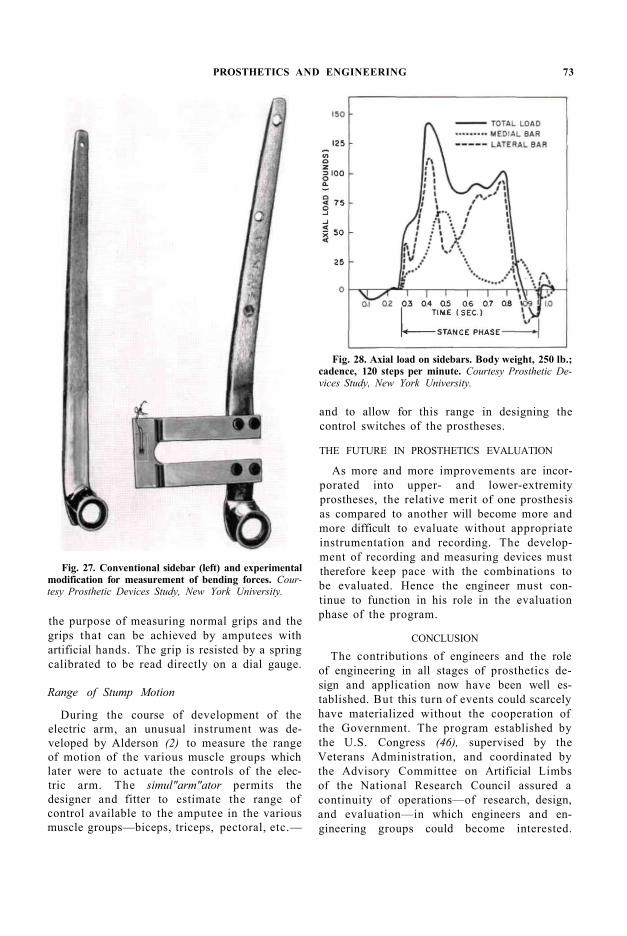
The third technique specially developed makes use of the strain gauge also described previously. By means of this instrument it has been possible to attack the problem of determining the relative distribution of body weight between the sidebars and the socket of the below-knee amputee. In the experimental procedure developed, modified sidebars (Fig. 27) are substituted for the original ones of the test subject. So constructed that the subject's gait is unaffected by the substitution, these modified sidebars permit the mounting of the strain gauges so as to simplify determination of axial and bending strains. In the test procedure, wires are run from the gauges on the bars to a recording oscillograph by means of an eight-conductor cable. Stick diagrams and force-plate records are taken simultaneously with the recording of the dynamic sidebar strains (Fig. 28). Thus, at any particular in
stant, the position of the leg in space, the forces it exerts on the ground, and the strains in the sidebars all are known. From the knowledge of the axial sidebar loads, plus some logical assumptions and some simple kinematic relationships, the components of socket load along the axis of the shank and normal to the shank axis can be found. At the present time, runs have been made on two test subjects, one unilateral and one bilateral, both wearing conventional wooden sockets (35).
Fig. 25. Experimental arrangement for pressure measurement using capacitors. Courtesy Prosthetic Devices Study, New York University.
THE UPPER EXTREMITY
Engineering techniques have been employed in the evolution of upper-extremity prostheses also, though not to the same extent. The refinements in lower-extremity prostheses are such as to require discrete, fine, and rapid measurements, while those in the upper extremity are comparatively gross and subject, in many cases, to visual observation and judgment. Moreover, the increased performance with the newer arms and terminal devices can be appreciated quite readily by both the am-
PROSTHETICS AND ENGINEERING 71
putee and the observer. In the upper extremity, therefore, the employment of measuring devices is required only in those special situations where human observations fail.
Fig. 26. Typical oscillograph record of forces in walking. Courtesy Prosthetic Devices Study, New York University.
Control Systems The efficiency of an upper-extremity con
trol system, from the point of load application at the harness to the point of pressure applied by the terminal device, cannot be obtained other than with measuring instruments. For such measurement, the strain gauge, applied to appropriately designed devices, can be used to measure the pressure at the tips of the fingers or the force applied at any point along the cable of an actuating system. In the course of some of the NYU studies, a channel-shaped structural element was designed in such a way that it could be inserted as a link in the cable system at different points along the cable.
Tension in the cable causes deflection in the elements, and the extent of deflection is recorded as a change in voltage through strain gauges cemented to the crossbar of the channel.
Finger Forces A similar principle has been used for meas
uring hook-finger pressures. Elements resembling tuning forks were designed, the beams being so shaped as to accommodate different grasps. Strain gauges cemented to the crossbar measure the bending stress in the fork, the stress being proportional to the pressure applied by the amputee at the tips of the hook fingers. With knowledge of the linkages involved in the system, it is possible to determine what harness combination is most efficient.
At the Army Prosthetics Research Laboratory, a "grip" meter has been developed for
72 CONTINI
the purpose of measuring normal grips and the grips that can be achieved by amputees with artificial hands. The grip is resisted by a spring calibrated to be read directly on a dial gauge.
Fig. 27. Conventional sidebar (left) and experimental modification for measurement of bending forces. Courtesy Prosthetic Devices Study, New York University.
Fig. 28. Axial load on sidebars. Body weight, 250 lb.; cadence, 120 steps per minute. Courtesy Prosthetic Devices Study, New York University.
Range of Stump Motion
During the course of development of the electric arm, an unusual instrument was developed by Alderson (2) to measure the range of motion of the various muscle groups which later were to actuate the controls of the electric arm. The simul"arm"ator permits the designer and fitter to estimate the range of control available to the amputee in the various muscle groups—biceps, triceps, pectoral, etc.—
and to allow for this range in designing the control switches of the prostheses.
THE FUTURE IN PROSTHETICS EVALUATION
As more and more improvements are incorporated into upper- and lower-extremity prostheses, the relative merit of one prosthesis as compared to another will become more and more difficult to evaluate without appropriate instrumentation and recording. The development of recording and measuring devices must therefore keep pace with the combinations to be evaluated. Hence the engineer must continue to function in his role in the evaluation phase of the program.
CONCLUSION
The contributions of engineers and the role of engineering in all stages of prosthetics design and application now have been well established. But this turn of events could scarcely have materialized without the cooperation of the Government. The program established by the U.S. Congress (46), supervised by the Veterans Administration, and coordinated by the Advisory Committee on Artificial Limbs of the National Research Council assured a continuity of operations—of research, design, and evaluation—in which engineers and engineering groups could become interested.
PROSTHETICS AND ENGINEERING 73
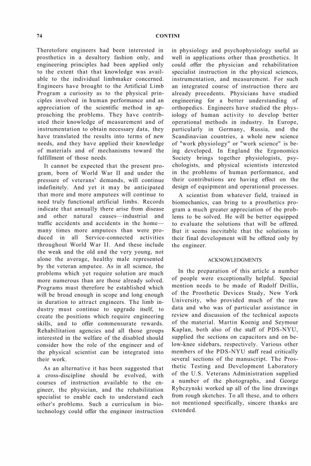
Theretofore engineers had been interested in prosthetics in a desultory fashion only, and engineering principles had been applied only to the extent that that knowledge was available to the individual limbmaker concerned. Engineers have brought to the Artificial Limb Program a curiosity as to the physical principles involved in human performance and an appreciation of the scientific method in approaching the problems. They have contributed their knowledge of measurement and of instrumentation to obtain necessary data, they have translated the results into terms of new needs, and they have applied their knowledge of materials and of mechanisms toward the fulfillment of those needs.
It cannot be expected that the present program, born of World War II and under the pressure of veterans' demands, will continue indefinitely. And yet it may be anticipated that more and more amputees will continue to need truly functional artificial limbs. Records indicate that annually there arise from disease and other natural causes—industrial and traffic accidents and accidents in the home— many times more amputees than were produced in all Service-connected activities throughout World War II . And these include the weak and the old and the very young, not alone the average, healthy male represented by the veteran amputee. As in all science, the problems which yet require solution are much more numerous than are those already solved. Programs must therefore be established which will be broad enough in scope and long enough in duration to attract engineers. The limb industry must continue to upgrade itself, to create the positions which require engineering skills, and to offer commensurate rewards. Rehabilitation agencies and all those groups interested in the welfare of the disabled should consider how the role of the engineer and of the physical scientist can be integrated into their work.
As an alternative it has been suggested that a cross-discipline should be evolved, with courses of instruction available to the engineer, the physician, and the rehabilitation specialist to enable each to understand each other's problems. Such a curriculum in biotechnology could offer the engineer instruction
in physiology and psychophysiology useful as well in applications other than prosthetics. It could offer the physician and rehabilitation specialist instruction in the physical sciences, instrumentation, and measurement. For such an integrated course of instruction there are already precedents. Physicians have studied engineering for a better understanding of orthopedics. Engineers have studied the physiology of human activity to develop better operational methods in industry. In Europe, particularly in Germany, Russia, and the Scandinavian countries, a whole new science of "work physiology" or "work science" is being developed. In England the Ergonomics Society brings together physiologists, psychologists, and physical scientists interested in the problems of human performance, and their contributions are having effect on the design of equipment and operational processes.
A scientist from whatever field, trained in biomechanics, can bring to a prosthetics program a much greater appreciation of the problems to be solved. He will be better equipped to evaluate the solutions that will be offered. But it seems inevitable that the solutions in their final development will be offered only by the engineer.
ACKNOWLEDGMENTS
In the preparation of this article a number of people were exceptionally helpful. Special mention needs to be made of Rudolf Drillis, of the Prosthetic Devices Study, New York University, who provided much of the raw data and who was of particular assistance in review and discussion of the technical aspects of the material. Martin Koenig and Seymour Kaplan, both also of the staff of PDS-NYU, supplied the sections on capacitors and on below-knee sidebars, respectively. Various other members of the PDS-NYU staff read critically several sections of the manuscript. The Prosthetic Testing and Development Laboratory of the U.S. Veterans Administration supplied a number of the photographs, and George Rybczynski worked up all of the line drawings from rough sketches. To all these, and to others not mentioned specifically, sincere thanks are extended.
74 CONTINI
LITERATURE CITED
1. Alderson, Samuel W., The electric arm, Chapter 13 in Klopsteg and Wilson's Human limbs and their substitutes, McGraw-Hill, New York, in press 1954.
2. Alderson Research Laboratories, Inc., New York City, Contractor's Final Report [to the U.S. Veterans Administration (Contract No. V1001M-3123)] on Research and development of electric arms and electric arm components, 1954.
3. Alldredge, Rufus H, Verne T. Inman, Hyman Jampol, Eugene F. Murphy, and August W. Spittler, The techniques of cineplasty, Chapter 3 in Klopsteg and Wilson's Human limbs and their substitutes, McGraw-Hill, New York, in press 1954.
4. Amar, Jules, Le moteur humaine et les bases scienli-fiques du travail professionel, H. Dunod, Paris, 1914.
5. Amar, Jules, Organisation physiologique du travail, H. Dunod et E. Pinot, Paris, 1917.
6. Bechtol, Charles O., The prosthetics clinic team, Artificial Limbs, January 1954. p. 9.
7. Bernshtein, N, Die Kymocyclographische Methode der Bewegungsunlersuchungen, in Hndb. d. biol. Arbeilsmethoden, Lief. 263., Urban und Schwar-zenberg, Wien, 1928.
8. Bernshtein, N., et at., Investigations on biodynamics of locomotion, Vols. 1 and 2, Moscow, 1935 and 1940. In Russian.
9. Borchardt, M., el at., eds., Ersatzglieder und Arbeit-shilfen, Springer, Berlin, 1919.
10. Borelli, Giovanni A., De molit animalium, Romae, 1679. Two volumes. To be found in Pathologie de chirurgie, Vol. 2 of 3 vols., by Jean Baptiste Ver-due, Paris, 1727.
11. Carlyle, Lester, Fitting the artificial arm, Chapter 19 in Klopsteg and Wilson's Human limbs and their substitutes, McGraw-Hill, New York, in press 1954.
12. Catranis, Inc., Syracuse, N.Y., Subcontractor's Final Report to the Advisory Committee on Artificial Limbs, National Research Council, Improved artificial limbs for lower extremity amputations, June 1954.
13. Committee on Artificial Limbs, National Research Council, Washington, D. C, Terminal research reports on artificial limbs [to the Office of the Surgeon General and the U.S. Veterans Administration] covering the period from 1 April 1945 through 30 June 1947.
14. Contini, R., and R. Drillis, Biomechanics, Appl. Mech. Rev., 7:49 (1954).
15. Drillis, R., Chronocyclographische Arbeitsstudien, in Psychophysiologische Arbeiten, 1A, Riga, 1930.
16. Drillis, R., Investigation on axe and woodcutting, Latvijas Lauksaimnieks, Riga, 1935. In Latvian.
17. Drillis, R., Investigations on stability, unpublished report, Prosthetic Devices Study, New York University, 1954.
18. Eberhart, H. D., and V. T. Inman, An evaluation of experimental procedures used in a fundamental
study of human locomotion, Ann. N. Y. Acad. Sci., 51:1213 (1951).
19. Eberhart, Howard D., and Jim C. McKennon, Suction-socket suspension of the above-knee prosthesis, Chapter 20 in Klopsteg and Wilson's Human limbs and their substitutes, McGraw-Hill, New York, in press 1954.
20. Elftman, H, The measurement of the external force in walking, Science, 88:152 (1938).
21. Elftman, H., The force exerted by the ground in walking, Arbeitsphysiol., 10:485 (1939).
22. Elftman, H., The basic pattern of human locomotion, Ann. N. Y. Acad. Sci., 51:1207 (1951).
23. Faries, John Culbert, Limbs for the limbless, Institute for the Crippled and Disabled, New York, 1934.
24. Fick, R., Handbuch der Anatomic und Mechanik der Gelenke unter Beriicksichtigung der bewegenden Muskeln, G. Fischer, Jena, 1904-1911. Three volumes.
25. Fischer, O., Theoretische Grundlagen fur eine Mechanik der lebenden Korper, mil speziellen Andwendungen auf den Menschen, B. G. Teubner, Leipzig and Berlin, 1906.
26. Fletcher, Maurice J., New developments in hands and hooks, Chapter 8 in Klopsteg and Wilson's Human limbs and their substitutes, McGraw-Hill, New York, in press 1954.
27. Fletcher, Maurice J., The upper-extremity prosthetics armamentarium, Artificial Limbs, January 1954.
28. Fletcher, Maurice J., and A. Bennett Wilson, Jr., New developments in artificial arms, Chapter 10 in Klopsteg and Wilson's Human limbs and their substitutes, McGraw-Hill, New York, in press 1954.
29. Frank, Wallace E., and Robert J. Gibson, New pressure sensing instrument, J. Franklin Inst., in press 1954.
30. Gilbreth, Frank B., and Lillian M. Gilbreth, Motion study for the handicapped, G. Routledge and Sons, Ltd., London, 1920.
31. Haddan, Chester C, and Atha Thomas, Status of the above-knee suction socket in the United States, Artificial Limbs, May 1954. p. 29.
32. Henschke, Ulrich K., and Hans A. Mauch, The improvement of leg prostheses, The Military Surgeon, 103(2) :135 (1948).
33. Hettinger, Th., and E. Midler, Der Einfluss des Schuhgewichies auf den Energieumsatz beim Gehen und Lastenlragen, Arbeitsphysiol., 15:33 (1953).
34. Inman, Verne T., and H. J. Ralston, The mechanics of voluntary muscle, Chapter 11 in Klopsteg and Wilson's Human limbs and their substitutes, McGraw-Hill, New York, in press 1954.
35. Kaplan, S., Determination of dynamic loads and strains in below-knee artificial limbs, unpublished report, Prosthetic Devices Study, New York University, 1954.
36. Leonard, Fred, and Clare L. Milton, Jr., Cosmetic gloves, Chapter 9 in Klopsteg and Wilson's Human limbs and their substitutes, McGraw-Hill, New York, in press 1954.
PROSTHETICS AND ENGINEERING 75
37. Leonardo da Vinci, On the human body, C. D. O'Malley and J. B. DeC. M. Saunders, eds. Schuman, New York, 1952.
38. Marey, E., Mouvement, G. Masson, Paris, 1894. 39. Marey, E.-J., and G. Demeny, Etudes experimen-
tales de la locomotion humaine, Compt. rend. Acad, d. sc., 106:544 (1887).
40. Martin, Florent, Artificial limbs, International Labour Office, Geneva, 1925.
41. Muybridge, Eadweard, The human figure in motion, Chapman & Hall, London, 1901.
42. New York University, College of Engineering, Research Division, [Report to the] Special Devices Center, Office of Naval Research (Contract No. N6onr-279), Investigations with respect to the design, construction, and evaluation of prosthetic devices, June 1, 1949. Two volumes.
43. New York University, Prosthetic Devices Study, [Report to the) Advisory Committee on Artificial Limbs, National Research Council, The functional and psychological suitability of an experimental hydraulic prosthesis for above-the-knee amputees, March 1953.
44. Northrop Aircraft, Inc., Hawthorne, Calif., Subcontractor's Final Report to the Committee on Artificial Limbs, National Research Council, A report on prosthesis development, 1947.
45. Parmelee, Dubois D., U.S. Patent 37,637, February 10, 1863, and reissue patents 1,907 and 1,908, March 4, 1865.
46. Public Law 729, Eightieth Congress, Second Session, Approved June 19, 1948.
47. Radcliffe, Charles W., Alignment of the above-knee artificial leg, Chapter 21 in Klopsteg and Wilson's Human limbs and their substitutes, McGraw-Hill, New York, in press 1954.
48. Radcliffe, Charles W., Mechanical aids for alignment of lower-extremity prostheses, Artificial Limbs, May 1954. p. 20.
49. Schede, Franz, Theoretische Grundlagen fur den Bau
von Kunslbeinen; Insbesondere fur den Ober-schenkelamputierlen, Ztschr. f. orthopad. Chir.;
Supplement 39, Enke, Stuttgart, 1919. 50. Schlesinger, G., Die Milarbeit des Ingenieurs bei der
Durchbildung der Ersatzglieder, Verein. Deutsch. Ingen., Berlin Ztschr., 61:6 (1917).
51. Steindler, Arthur, Mechanics of normal and pathological locomotion in man, Charles C Thomas, Springfield, 111., 1935.
52. Taylor, Craig L., Control design and prosthetic adaptations to biceps and pectoral cineplasty, Chapter 12 in Klopsteg and Wilson's Human limbs and their substitutes, McGraw-Hill, New York, in press 1954.
53. Taylor, Craig L., The biomechanics of the normal and of the amputated upper extremity, Chapter 7 in Klopsteg and Wilson's Human limbs and their substitutes, McGraw-Hill, New York, in press 1954.
54. Technical Institute, Charlottenburg, Report of the Special Commission for Accident Prevention, Merkblatter der Priifungsstelle fur Ersatzglieder, Berlin, 1916-1917.
55. Thomas, A., and C. C. Haddan, Amputation prosthesis, Lippincott, Philadelphia, 1945.
56. University of California (Berkeley), Prosthetic Devices Research Project, Subcontractor's Final Report to the Committee on Artificial Limbs, National Research Council, Fundamental studies of human locomotion and other information relating to design of artificial limbs, 1947. Two volumes.
57. Wagner, Edmond M., Contributions of the lower-extremity prosthetics program, Artificial Limbs, May 1954.
58. Wagner, Edmond M., and John G. Catranis, New developments in lower-extremity prostheses, Chapter 17 in Klopsteg and Wilson's Human limbs and their substitutes, McGraw-Hill, New York, in press 1954.
59. Wilson, A. Bennett, Jr., The APRL terminal devices, Orthop. & Pros. Appl. J., March 1952.
76 CONTINI