Prospects of implant with locking plate in fixation of ... · Prospects of implant with locking...
34
1 Prospects of implant with locking plate in fixation of subtrochanteric fracture: experimental demonstration of its potential benefits on synthetic femur model with supportive hierarchical nonlinear hyperelastic finite element analysis Mohammed Hadi Latifi 1,2 , Kualan Ganthel 1,2 , Shanmugam Rukmanikanthan 1,2 , Azura Mansor 1,2 , Tunku Kamarul 1,2 and Mehmet Bilgen 3 , 1 Tissue Engineering Group, National Orthopaedic Center of Excellence in Research and Learning, 2 Department of Orthopedic Surgery, 3 Health and Translational Medicine, Faculty of Medicine, University of Malaya, 50603 Kuala Lumpur, Malaysia Keywords: Locking plate, angle blade plate, dynamic condylar screw plate, subtrochanteric fracture, biomechanics, finite element analysis, hierarchical finite element modelling Corresponding Author: Mehmet Bilgen.,Ph.D. Health and Translational Medicine Faculty of Medicine University of Malaya 50603 Kuala Lumpur, Malaysia Email: [email protected] Tlf: +6016 637 0426
Transcript of Prospects of implant with locking plate in fixation of ... · Prospects of implant with locking...

1
Prospects of implant with locking plate in fixation of subtrochanteric fracture:
experimental demonstration of its potential benefits on synthetic femur model
with supportive hierarchical nonlinear hyperelastic finite element analysis
Mohammed Hadi Latifi1,2
, Kualan Ganthel1,2
, Shanmugam Rukmanikanthan1,2
, Azura Mansor1,2
, Tunku
Kamarul1,2
and Mehmet Bilgen3,
1Tissue Engineering Group, National Orthopaedic Center of Excellence in Research and Learning,
2Department
of Orthopedic Surgery, 3Health and Translational Medicine, Faculty of Medicine, University of Malaya, 50603
Kuala Lumpur, Malaysia
Keywords: Locking plate, angle blade plate, dynamic condylar screw plate, subtrochanteric fracture,
biomechanics, finite element analysis, hierarchical finite element modelling
Corresponding Author:
Mehmet Bilgen.,Ph.D.
Health and Translational Medicine
Faculty of Medicine
University of Malaya
50603 Kuala Lumpur, Malaysia
Email: [email protected]
Tlf: +6016 637 0426
2
Abstract
Background: Effective fixation of fracture requires careful selection of a suitable implant to provide stability
and durability. Implant with a feature of locking plate (LP) has been used widely for treating distal fractures in
femur because of its favourable clinical outcome, but its potential in fixing proximal fractures in the
subtrochancteric region has yet to be explored. Therefore, this comparative study was undertaken to
demonstrate the merits of the LP implant in treating the subtrochancteric fractures by comparing its
performance limits against those obtained with the more traditional implants; angle blade plate (ABP) and
dynamic condylar screw plate (DCSP).
Materials and Methods: Nine standard composite femurs were acquired, divided into three groups and fixed
with LP (n=3), ABP (n=3)and DCSP (n=3). The fracture was modeled by a 20 mm gap created at the
subtrochanteric region to experimentally study the biomechanical responses of the implants under axial static
and dynamic loading paradigms. To confirm the experimental findings and to understand the critical
interactions at the boundaries, the synthetic femur/implant systems were numerically analyzed by constructing
hierarchical finite element models with nonlinear hyperelastic properties. The predictions from the analyses
were then compared against the experimental measurements to demonstrate the validity of the numeric model,
and to characterize the internal load distribution in the femur and load bearing properties of each implant.
Results: The average measurements indicated that the constructs with ABP, DCPS and LP respectively had
overall stiffness values of 70.9, 110.2 and 131.4 N/mm, and exhibited reversible deformations of 12.4, 4.9 and
4.1 mm and plastic deformations of 11.3, 2.4 and 1.4 mm at the applied dynamic loads of 400 N and 1000 N.
The corresponding peak cyclic load to failure was 1100, 1167 and 1600 N. The errors between the
displacements measured experimentally or predicted by the nonlinear hierarchical hyperelastic model were less
than 18 %. In the implanted femur heads, the principal stresses were spatially heterogeneous for ABP and
DCSP but more homogenous for LP, meaning lower the stress concentrations.

3
Conclusion: When fixed with the implant augmented with LP, the synthetic femur model of subtrochancteric
fracture consistently exceeds in the key biomechanical measures of stability and durability. This capability
makes the LP impant potentially a viable alternative to conventional ABP or DCSP for the clinical treatment of
the subtrochancteric femur fracture.

4
Background
Subtrochanteric femur fracture (SFF) is a common occurrence and requires surgical intervention with an
orthopaedic implant [1]. A stable fixation restores the weight bearing function of the bone and provides a stable
environment for fracture healing. Angle blade plates (ABP) and dynamic condylar screw plate (DCSP) are the
two extramedullary implants commonly used for fixing SFF. At the time of surgery, fixation with either
implant may appear stable, but eventually fails at a rate of 20-30% within the first 12 weeks of surgery [2]. The
early failure is largely attributed to the inability of the implants to withstand typical loading conditions
experienced during normal human activities.
Locking plate (LP) is another orthopaedic implant, but used mainly for stabilizing the distal fractures of the
femur near the knee with favourable long-term outcome [3, 4]. Because of its contour fitting well to the contra
lateral surface of the proximal femur, LP has also been considered as an alternative option for the fixation of
SFF. Unlike ABP and DCSP, LP exploits a different strategy and employs multiple screws equipped with a
special locking mechanism. Such capability prevents slippage or loosening of the screws when mounted into
the head or shaft of the femur. This particular implant also leaves a small gap between the plate and bone
surfaces to maintain periosteal blood supply. These features collectively make LP an attractive alternative over
the other implants ABP and DCSP [5]. Based on its success record in fixing the distal femur fractures, we
hypothesized that, when feasible, LP would also yield more robust fixation of the SFFs by supporting more
uniform load distribution in the bone/implant interfaces, especially in the regions surrounding the fastening
points of the implant. The end configuration of the SFF fixation with LP would therefore provide more durable
mechanical environment as compared to those achieved with the conventional implants ABP and DCSP.
In this study, we tested the performances of the three implants ABP, DCSP and LP with both experimental
and numerical approaches. Experiments were conducted on simulated femur constructs where the implants
were secured to the outer contours of the synthetic femurs by following the procedures identical to those
performed in a typical SFF surgery. Then, a 20 mm long segment was cut off and removed completely from the
subtrochanteric region of each sample. The created gap was intentionally made large to produce an extreme

5
case of fracture, which enabled studying the biomechanical response of each individual implant design alone
without the interference from the fracture itself or its opposing interface surfaces on different loading
conditions. The sample models with implants were subjected to biomechanical tests using axial compressive
loading under both static and dynamic conditions. The resulting measurements were recorded and compared for
evaluating the load bearing properties and failure limits of each implant. To mechanistically understand the
critical interactions at the implant boundaries and also to confirm the experimental measurements, finite
element analyses of the synthetic femur/implant systems were also performed in parallel. The investigations
involved constructing hierarchical finite elements with nonlinear hyperelastic properties and performing
computations to characterize the internal load distribution in the femur and load bearing properties of each
implant. The numerical predictions were then compared against the experimental data to demonstrate the
validity of the numeric models and explain the experimental measurements. In the following sections, we
describe each of these processes and discuss our findings in detail within the scope of whether the implant LP
would offer better biomechanical performance in fixing SFF than the other two implants ABP and DCSP.
Materials and Methods
Synthetic femur and implants
Nine small size simulated femurs representing the left side were purchased from a commercial company
(Sawbones, Pacific Research Laboratories, Inc., Vashon, WA, USA). The simulated femurs were constructed
using a fourth generation composite technology to be nearly identical to the real human femur in terms of its
biomechanical structure, function and property [6]. The age and quality of the cadaveric bone affects its
stiffness and hence yields variations in biomechanical response from one sample to the next [7]. For this
reason, composite femurs are well utilized in mechanical testings and preferred over the corresponding
cadaveric femur for minimizing the interspecimen variation. Three sets of implants; 130o angle blade plate
(ABP) and dynamic condylar screw plate (DCSP), both made of standard stainless steel, and a locking plate
(LP) implant made of titanium alloy were all purchased from the same company Synthes® with catalog
numbers 238.98, 237.94 and 422.255, respectively (Synthes, Inc., Solothurn, Switzerland). The pictures of the
implants are shown in Fig. 1 and their specifications were summarized in Table.

6
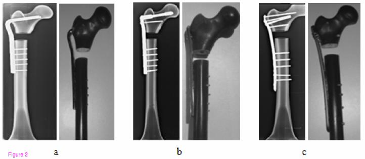
The implants were first fixed to the synthetic femurs. Then, osteotomy was performed at 70 mm distal from
the tip of the greater trochanter in the subtrocthanteric region. Below this region, a segmental defect measuring
20 mm in length was created. The resulting medial calcar comminution was considered as the extreme
representation of SFF. This arrangement allowed studying the biomechanical response of the individual
implant design without the interference from the bone/fracture interaction when the fracture was only partial or
not complete across the bone. Subsequently, radiographic and photographic images of the femur/implant
constructs were acquired for visual display and mesh generation in finite element analysis. Figure 2 compares
the constructs with three different plate designs side-by-side. The closest distance between the implant
elements mounted in the proximal and distal segments of the femur was considered as working length. The
working lengths were nearly identical for all the implants, as depicted by the radiographic images in Fig. 3.
Mechanical testing of the constructs
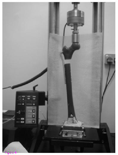
The femur constructs were all tested mechanically under both static and dynamic loading conditions using a
materials-testing machine (Instron 5800 R, Canton, MA, USA), as shown in Fig. 4. The distal femoral condyle
was fixed using a dental stone enclosed within a custom-built jig for positioning at the base of the Instron
machine. During the test, the femoral head was placed under a stainless steel jig with a concave depression
physically conforming the superior curvature of the head. With the help of a plummet, each construct was
aligned vertically so that the applied compression was in line with the mechanical axis of the construct in both
sagittal and coronal planes.
The static axial loading was performed under the mode of linear elastic control and involved an initial 50 N
of preloading that was followed by displacement at a rate of 10 mm/min until 500 N of load was reached, as
described previously [8]. At the maximum load of 500 N, the axial deformation of each construct exhibited
linear elastic behaviour. Otherwise, plastic deformation would stop the operation of the Instron machine. Force
and displacement measurements were read and stored by using Bluehill2® software, which was provided by the
manufacturer of the Instron machine. The temporal profiles of the force and displacement measurements
exhibited nearly a linear trend when plotted on the same graph, and hence fitted to a linear function using
regression analysis by forcing the final fit to intersect at zero. The stiffness of the overall construct was
7
estimated from the slope. The stiffness obtained from the static loading of each construct was a critical
parameter and compared against the one predicted by the corresponding numerical model, which was simulated
identical to the experimental condition, as described below. .
The dynamic axial loading protocol started similarly with a preload of 50 N and followed by a cyclic
loading of 300 N force applied under the displacement control mode of 1 mm/s. After reaching the ten cycles,
the load was incremented by 100 N without stopping, and the test was repeated with 400 N. This incremental
loading paradigm with ten cycles in each phase continued until the implant was maximally deformed and that
the two medial edges of the implanted sites of the femur came to contact. At this point, the amount of the load
was recorded as the indicator of the peak cyclic load to failure. The magnitudes of the minimum and maximum
displacements during each phase of the cyclic loading were measured to determine the reversible and
irreversible (plastic) deformations [9]. The reversible deformation was determined as the average difference
between the distances of the distal and proximal edges of the gap before and after each cycle of the loading.
The plastic deformation was another critical parameter used for determining the durability of the implants and
comparing their performances. It was defined as the minimum distance, i.e., the distance from the top portion
of the curve to the zero line.
Finite element models of the constructs
Finite element model (FEM) of each construct was built to numerically simulate the geometric and material
properties of the femur constructs with specific implants as realistically as possible based on the underlying
structural hierarchy using software ABAQUS (FEA Solver, Realistic Simulation and 3D analysis - Dassault
Systèmes, Villacoublay Cedex, France). This process required information about the actual geometry
describing the contours of the internal and external surfaces of the synthetic femur, the internal boundaries
between its cortical and cancellous sections and the geometry of the elements of each implant. Each construct
was imaged using a computer tomography scanner (As+128 Somatom model, Siemens, Inc., Henkestrasse,
Germany). The image acquisition parameters were 140 kVp; 80 mA; 1 s; slice thickness = 0.6 mm and number
of slices = 757, which covered the whole length of the construct. The acquired images visualizing the synthetic
femur in transverse plane were postprocessed offline to segment out its cortical and cancellous sections. The

8
brightness and contrast of a selected image in the series were first adjusted until we could clearly differentiate
the boundary between the cortical and cancellous regions. Next, a threshold value was selected manually from
the spatial intensity distribution of the image and applied to segment out these two distinct regions. Figure 5
shows an example obtained by this approach. We note that the same threshold value was applied to the other
remaining images of the femur simultaneously to achieve segmentation in 3 D.
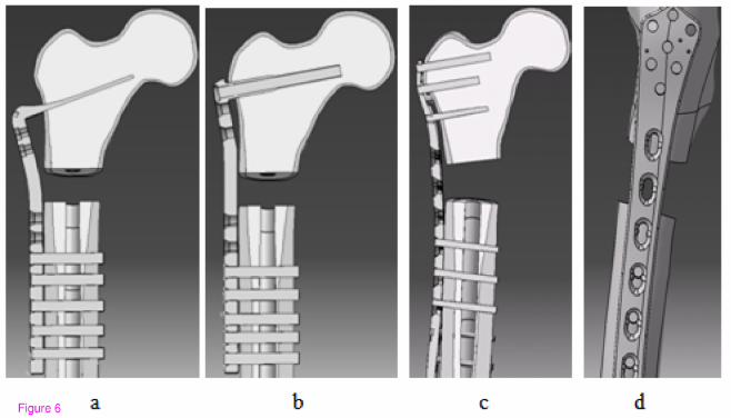
The plates and screws of each implant were adapted into the 3 D geometry of the femur construct. The
implants were sent to a company (KL Analytical Sdn Bhd, Kuala Lumpur, Malaysia) to generate their digital
representations in 3 D. The screw holes in the plates were further trimmed using software CATIA V5 (Virtual
Design for Product Excellence - Dassault Systèmes, Villacoublay Cedex, France). Each screw was modelled as
a filled cylinder with no treading. The screw bodies were removed from the cortical and cancellous sections
according to the implant design. The plates, screws and synthetic femur were all assembled together using
again CATIA V5 and imported to ABAQUS. The sharp surfaces were filleted to avoid mesh irregularities or
highly distorted elements. Figure 6 shows the geometries of the final constructs given in coronal view along the
midline (a-c) and the side view (d).
Assignments of the hyperelastic material properties
Material properties of the cortical and cancellous sections of the constructs were measured experimentally
according to the ASME load-stroke protocol [10]. Uniform cubic samples with 1 cm in each direction were
first removed from the cortical and cancellous sections of the synthetic femur and tested using the Instron
machine to determine the corresponding hyperelastic properties. The tests were performed under uniaxial
compression and tensile conditions which were applied at a displacement rate of 10 mm/min. This rate is
typically set as reference in characterizing the composite systems [11]. The resulting nominal stress-strain
measurements were promptly fed into ABAQUS using its hyperelastic subdivision with Neo-Hookian as strain
energy potential and uniaxial volumetric test data option. The stress-strain measurements from the cubes were
also analyzed independently to determine the elastic properties of the composite materials used in the cortical
and cancellous sections of the synthetic femur. Table 2 lists the results obtained experimentally as well as those
reported by the manufacturer of the synthetic femur. We note that our estimates were based on the readings

9
taken from the displacement points where the cubes were either started to break under the tensile or ruptured
under the compressive loading. This meant that the estimation range covered beyond the linear region and
hence included nonlinearity in the stress-strain curve. Comparing the corresponding values in the table, the
inclusion of the nonlinearity may explain why our measurements yielded slightly lower values for the
mechanical properties (as defined by strength and modulus parameters) under both the tensile and compressive
loading conditions. Because of this difference, we opted to use the hyperelastic definition in the numerical
simulations, as described above. With this choice, Poisson ratio was calculated inherently by ABACUS from
the imported data.
The plates of the implants were defined by homogeneous linear elastic properties. The elastic modulus and
possion ratio for the metal of each plate were determined from the literature and listed in Table 3 [8]. The
values in the table were accordingly assigned to the geometry of the corresponding plate in ABAQUS.
Interactions between the implant and composite femur interfaces
Numerical modelling using ABAQUS required specifying the mechanical contact properties in the implant
and composite femur system. The contact property options in the software included normal and tangential
interactions between two materials with a common interface.
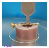
The normal behaviour between the screw and composite femur was derived from a separate standard
penetration test. In this test, a piece of composite femur was segmented out from its shaft, a screw was placed
horizontally on its top and compression load was applied on the screw through the tip of the Instran machine, as
shown in Fig 7. The pressure-oveclosure data obtained from this test were fed into ABAQUS. In the software,
the constrained enforcement method was set as standard and pressure-overclosure was set as hard contact. The
contact stiffness behaviour was defined as nonlinear and maximum stiffness value was set as default. Under the
default option, the software automatically fitted the data to an exponentical function describing the normal
contact behaviour indicated by stiffness scale factor=1, initial/final stiffness ratio=0.01, upper quadratic limit
scale factor=0.03, lower quadratic limit ratio=0.3333 and clearance at which contact pressure = 0.
The tangential behaviour between the screw and composite femur was defined as rough. This setting
indicated that the two points contacting each other between the screw and femur elements would not slip.

10
For ABP, the normal behaviour of the interaction between the blade and femur head was described by hard
contact. But, the tangential behaviour was defined with the selections: friction formulation = penalty,
directionality = isotropic, friction coefficient =3.76 and shear stress limit = 200. The values for the friction
coefficient and shear stress limit were determined from the pull out test, which was performed by following the
procedures in [12]. The interactions in all remaining interfaces between the plates and femur shaft were defined
by normal behaviour only, but with hard contact option.
For the interactions between the screws and blades of ABP and DCSP, the normal behaviour was set to hard
contact and the tangential behaviour was set to frictionless. For LP, however, because of the locking
mechanism on the screw heads, direct normal and rough tangential behaviours were defined between the screws
and the blade.
Boundary conditions and loading
The interface between the cortical and cancellous sections of the synthetic femur were bind together
according to the ENCASTRE definition under the boundary-condition option of ABAQUS. This option
allowed rigidly joining the finite elements with a common border shared by the two sections. To simulate the
stable positioning of the constructs on the Instron machine, the surface nodes of the methacondylar section of
the digitized femur construct was constrained so that they would not move freely. But, the other digitized
external and medullar surfaces of the synthetic femur was set free, meaning that they were allowed to move
freely in six degrees of freedom.
For applying static compressional force, a point source has been assigned on the finite element node at the
highest altitude in the digitized femur head and its direction was set vertical. To mimic the static experimental
condition, a preload of 50 N was absorbed into the force applied initially and this force was set to a magnitude
of 150 N at the first step and incremented by 100 N in the following 5 steps until the final load of 550 N was
reached.
Furthermore, in the software, general static steps were defined for loading increments. And step
incremental size decreased to 1x10⁻⁸
for faster and more accurate convergence.
Mesh Generation

11
The synthetic femur of the construct was meshed using MIMICs (Materialise's Interactive Medical Image
Control System, Leuven, Belgium) and its other components were digitized using ABAQUS. The protocol for
meshing the cortical and cancellous sections of the synthetic femur involved cubic elements with 16 nodes that
were assigned to the shaft sections and tetrahedron elements with 4 nodes that were assigned to the trochanter,
femoral head and methacondyles sections. The connection screws of each implant were digitized using 16-node
cubic elements and the blade geometries were represented using 4-node tetrahedron elements. Standard
quadratic elements were assigned to all of the remaining components of each construct.

12
Results
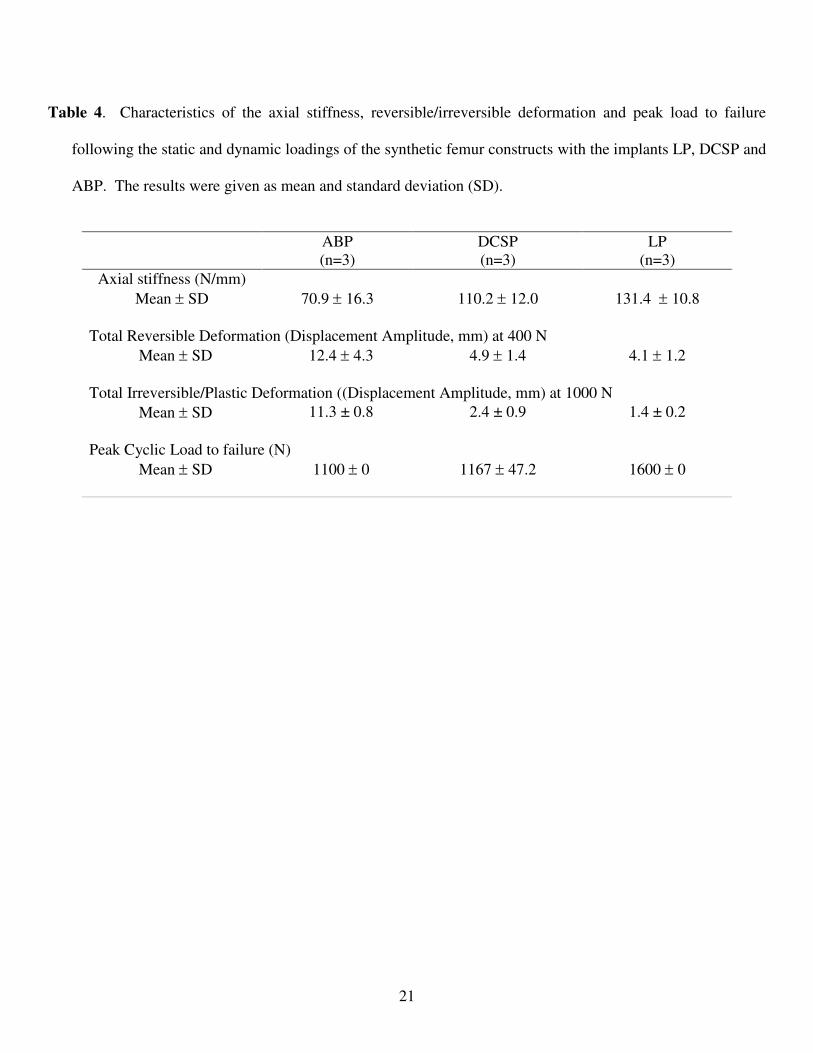
The measurements of the biomechanical parameters of interest from the experimental tests on the synthetic
femur constructs under the static and dynamic loading conditions were listed in Table 4. During the static tests,
all of the constructs remained intact. LP exhibited greatest axial stiffness with a mean value of 131.4 N/mm and
the corresponding values for the ABP and DCSP were 70.9 N/mm and 110.2 N/mm, respectively.
The other measurements in Table 4 were associated with the dynamic axial loading of the constructs and
derived from the cyclic plots similar to those shown in Fig. 8. The reversible and irreversible (plastic)
deformations were calculated at each increment of the dynamic loading. The overall temporal trends in the
curves indicate that the amount of plastic deformation was greatest for the construct with ABP, lesser with
DCSP and least with LP. When the deformation was analyzed in the linear range at the applied compression
level of 400 N, the mean reversible deformation was minimal at 4.1 mm for LP, but attained slightly larger
value of 4.9 mm for DCSP and reached 12.4 mm for the ABP construct. The nonlinear behaviours of the
constructs in response to the cyclic compression were evaluated at a larger load of 1000 N. The mean plastic
deformation was measured as 1.4 mm for LP, which was significantly lower than 11.3 mm for ABP but to a
lesser degree when compared to 2.4 mm for the DCSP construct. The mean measurements of the peak load to
failure indicated that the LP construct had the highest strength 1600 N versus 1100 N for the ABP construct and
1167 N for the DCSP construct.
The above results from the static and dynamic experiments indicated that, as compared to both ABP and
DCSP, the femur constructs with LP had significantly improved rigidity, stability and durability, which were the
important biomechanical characteristics expected of a good implant fixation of the fractured bone.
The hyperelastic finite element models o the implanted synthetic femurs were used to compute the vertical
displacement of the top portion of the femur head where the static load was applied, the stress induced by the
plates on the proximal and distal elements of the femur and also the stress distribution internal to the femur.
The unloaded length of each femur construct was a prior knowledge used in the FE modelling but the
shortened lengths after the static compression was obtained experimentally by the displacement of the stainless
steel jig of the Instron machine and also estimated numerically from the FE analysis of the deformed femur
13
construct under the specific load value for comparison. The experimental measurements and numerical
estimates on the vertical displacements were listed in Table 5 for each loading step. The difference between the
displacements from the experiment and the FE analysis were expressed as percentage errors and also given in
the table. The small amount of errors (<20%) at each applied load indicated that the numerical models of the
ABP, DCSP and LP constructs closely represented the biomechanics of the real femur construct under the static
loading conditions.
The maximum and minimum principal stresses in the femoral head were shown in Fig. 9 for all the three
implant types. Table 6 compares the maximum and minimum principal stresses obtained under the maximum
static load of 500 N. According to the data in Fig. 9, the principal stress was spatially nonuniform for the ABP
and DCSP implanted femur heads. The stress was mostly concentrated in the areas nearby the blade of ABP or
condylar screw of DCSP. The overall loading pattern of the stress distribution was such that the bending action
of the force applied on the top surface of the femur appeared to shear the blade and the condylar screw. This
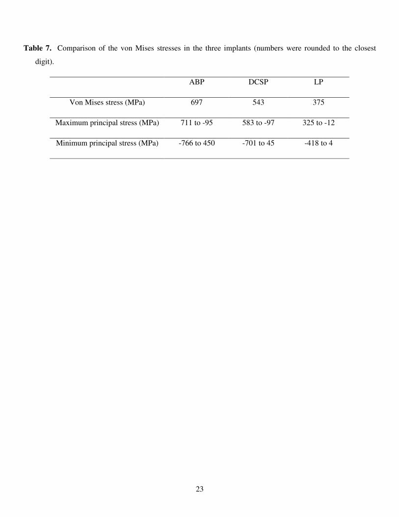
effect was more visible in Fig. 10 which depicts the von Misses stress distributions in the femur head. The
maximum values of the von Misses stresses were given in Table 7 along with the ranges of maximum and
minimum principal stresses measured in the implants. The more uniform maximum and minimum principal
stresses induced in the femur head with the LP implant implied that the load distribution was more
homogeneous in the femoral head. Combining these results all together suggested that the LP implant induces
lesser stress concentration in the femur than the ABP and DCSP implants.
14
Discussion
In this study, we compared the performances of the three implants ABP, DCSP and LP in fixing SFF. Our
investigation strategy involved first using a synthetic femur model, second modelling the subtrochanteric
fracture by a large gap, third examining the fixations with experimental tests under both static and dynamic
loading conditions, fourth performing FE analysis on the simulated constructs and finally comparing the results.
Performing the study with the synthetic femur rather than the cadaveric specimens improved the
reproducibility of the results by reducing the intergroup variability, as such has also been reported reported
earlier [13]. However, representing the fracture by a large gap instead of a hair-line crack was a novel approach
not employed previously [14]. It made sure that the evaluation of the biomechanical performance of the
construct was solely based on the characteristic biomechanical response of each individual plate only, but not
due to the interaction between the bone-to-bone surfaces at the proximal and distal surfaces of the fracture. In
this configuration, the weight was supported across the cross-sectional area of the plate in each implant. The
transverse dimensions of ABP and DCSP were 4.0% and 5.9% larger physically than that of LP, respectively.
Since the working length remained nearly the same in all of the constructs (Fig. 3), the material volume
occupying the length of the fracture was the lowest in LP as compared to ABP and DCSP. In addition, the
overall weights of ABP and DCSP were 57.7% and 79.4% heavier than that of LP. The composition and tissue
compatibility are two critical factors deciding the biomechanical superiority of the plate material and the
healing of bone after the implantation. Plates made of titanium were reported to increase the cortical stiffness
and bone density by 69% and 30% respectively as compared to those using stainless steel [15]. These
favourable features of LP provide the first set of evidence supporting its advantage over ABP and DCSP in
fixing SFF.
Both static and dynamic lading conditions of the constructs allowed measuring the key mechanical
parameters that defined the stiffness as well as the stability and durability of the constructs. Our data in Table 1
demonstrated that LP consistently exceeded in these measures compared with ABP and DCSP. As mentioned
in introduction, LP offers the capability of percutaneous fixation with interlocking mechanism between the
15
screw head and the plate. This feature stabilizes the bone fragments by means of attachment of the screw to the
plate in a rigid fixed angle coupling. A fix angle device prevents excessive toggling between the screw and the
plate, which in turn provides high pullout strength as well as increase in rigidity [16]. This capability makes LP
a superior implant in treating unstable fractures, such as SFF. This becomes more so, when considering that the
implant is required to resist large amount of compressive axial loading to provide stability for the patient
mobilization. While walking, the femur is subjected to axial and bending loads as a result of the neck of femur
angle or the off-set position of the femur from the trunk. This exposes the medial cortex to compressive loads
while the lateral cortex is undergoing tensile loading. A stiffer implant like LP would therefore be the preferred
choice during the early weight-bearing period as it reduces excessive motion at the fracture site. Consequently,
potential future complications which include non-union, malunion and joint degeneration would be prevented
[17].
The FE analysis demonstrated the spatial stress distributions and areas of stress concentrations in the femur
heads and the implants (Fig. 9). Such additional information on the biomechanical response of each construct
could not be retrieved based on just the experiments. The data indicated that, in the LP implanted femur, the
stress concentration on the head screws was much lower and more homogenous compared with those of ABP
and DCSP. The multi-screw load carrying design on the head section of LP explains this positive outcome.
With both ABP and DCSP, the exerted load was carried by the plate with only one connector device (whether
the blade or condylar screw), but with LP, the load was transmitted with the help of 5 connector screws fastened
into the femur head. The “multi-fastening” contour made the implanted femur construct more stable and
reduced the stress concentrations by increasing the area of the load sharing or dividing the applied load through
the screws [18]. From the aspect of clinical application, the lower amount of induced stress variations and
concentrations in SFF fixation with LP decreases the risk factor associated with the crack development in the
implanted femurs.
In this study, static loading was limited to only axial compression. Tests involving torsion of the constructs
provide further information considering that this form of loading occurs in real life biological conditions.
However, the use of the current loading protocol was the most appropriate since the compressive axial loading
16
constitutes the dominant force that would be present during the partial weight bearing [19]. Therefore, in its
present form, to the best of our knowledge, our results provide a baseline comparison of the biomechanical
properties of the three implants using the latest experimental and numerical tools.
The use of implant-synthetic femur construct does not represent the true biological conditions where the
biomechanics of the femur is influenced by the presence and attachment of the surrounding soft tissues.
Numerically simulating such comprehensive model would be too complex. As in any in-vitro system,
understandably, it would be particularly difficult to predict the actual clinical outcome based solely from the
results of the current study when considering that a multitude of factors, including patient’s age, social habits,
behaviour and smoking etc., can affect the performance of the fixation.
In the FE modelling, the CT images were acquired with a clinical scanner and had thickness of 0.6 mm,
which could have been further reduced if the samples were scanned with a microCT scanner. Mesh protocol for
the cortical and cancelous sections of the composite femur were completed without using special meshing tools
but only the MIMICS software. Because of the complex geometry of the femur especially the head and
trochanter regions, we couldn’t use cubic elements in all segments but instead used tetrahedron elements. This
selection reduced the computational time. The representations of the screws in the FE modelling were
simplified by using cylinder shaped pins inserted into the bone to avoid the convergence to a unique solution
and also to prevent unrealistic distortion of the elements during the analysis. The bone-screw contact interfaces
were defined by stiffness and tangential behaviours, as justified by the data obtained from the experimental
indentation test.
The main purpose of the FE analysis was to create a numerical platform for comprehending and explaining
the findings derived from the experiments. The analysis predicted the experimental data with less than 18 %
error in each step of the static loading. The assignment of the hyperelastic properties to the cortical and
cancellous sections of the composite femur together with the use of hierarchical framework may be the reason
of such low levels of errors. Combining all these factors together, the FE models developed for the three
implants in this study can potentially be further expanded and turned into a more generic form of a simulation
platform for studying the performance of any other existing or future implant [20].
17
Conclusion
Treating the subtrochanteric fracture of the femur is difficult and, to date, there is no one ideal implant
suitable for its fixation. Our data indicate that the titanium implant LP is capable of providing more stable and
durable fixation of the subtrochanteric fracture when compared to the conventional stainless steel implants ABP
and DCSP. The superior biomechanical and material properties suggest that the LP implant is less likely to fail
when used for fixing the subtrochanteric fractures in humans. This implant can be fixed percutaneously, and
hence an extensive lateral approach as with conventional ABP and DCSP, thereby limiting periosteal striping
and minimizing blood loss. Its capability of reducing non union, mal union implant failure and infection has
been demonstrated in part in several clinically oriented papers, but further studies with large patient population
are still warranted to rigorously demonstrate that it is a viable alternative. Also, as the understanding of the
biology and biomechanics of the fractures evolve with time, new implants are likely to be designed by
incorporating the acquired knowledge and performance-wise tested against those currently in use. The
experimental paradigm and numerical analysis, outlined in this paper, can be used for this purpose.

18
References
1. Sims SH: Subtrochanteric femur fractures. Orthop Clin North Am 2002, 33:113-126, viii.
2. Kulkarni SS, Moran CG: Results of dynamic condylar screw for subtrochanteric fractures. Injury 2003,
34:117-122.
3. Acklin YP, Bereiter H, Sommer C: Reversed LISS-DF in selected cases of complex proximal femur
fractures. Injury 2010, 41:427-429.
4. Ma CH, Tu YK, Yu SW, Yen CY, Yeh JH, Wu CH: Reverse LISS plates for unstable proximal femoral
fractures. Injury 2010, 41:827-833.
5. Ganthel K: Biomechanical comparison of condylar locking plate to angle blade plate and dynamic
condylar screw in subtrochanteric femur fracture University of Malaya, Orhopaedic Surgery; 2010.
6. Zdero R, Bougherara H, Dubov A, Shah S, Zalzal P, Mahfud A, Schemitsch EH: The effect of cortex
thickness on intact femur biomechanics: a comparison of finite element analysis with synthetic
femurs. Proc Inst Mech Eng H 2010, 224:831-840.
7. Heiner AD, Brown TD: Structural properties of a new design of composite replicate femurs and tibias.
J Biomech 2001, 34:773-781.
8. Floyd JC, O'Toole RV, Stall A, Forward DP, Nabili M, Shillingburg D, Hsieh A, Nascone JW:
Biomechanical comparison of proximal locking plates and blade plates for the treatment of
comminuted subtrochanteric femoral fractures. J Orthop Trauma 2009, 23:628-633.
9. Calafi LA, Antkowiak T, Curtiss S, Neu CP, Moehring D: A biomechanical comparison of the Surgical
Implant Generation Network (SIGN) tibial nail with the standard hollow nail. Injury 2010, 41:753-
757.
10. Martins PALS, Jorge NRM, Ferreira AJM: A Comparative Study of Several Material Models for
Prediction of Hyperelastic Properties: Application to Silicone-Rubber and Soft Tissues. Strain 2006,
42:135-147.

19
11. Rong MZ, Zhang MQ, Zheng YX, Zeng HM, Walter R, Friedrich K: Structure-property relationships of
irradiation grafted nano-inorganic particle filled polypropylene composites. Polymer 2001, 42:167-
183.
12. Nairn JA: Analytical fracture mechanics analysis of the pull-out test including the effects of friction
and thermal stresses. Advanced Composites Letters 1999, 9:373-383.
13. Jakubowitz E, Kinkel S, Nadorf J, Heisel C, Kretzer JP, Thomsen MN: The effect of multifilaments and
monofilaments on cementless femoral revision hip components: an experimental study. Clin Biomech
(Bristol, Avon) 2011, 26:257-261.
14. Sowmianarayanan S, Chandrasekaran A, Kumar RK: Finite element analysis of a subtrochanteric
fractured femur with dynamic hip screw, dynamic condylar screw, and proximal femur nail implants-
-a comparative study. Proc Inst Mech Eng H 2008, 222:117-127.
15. Hasegawa K, Abe M, Washio T, Hara T: An experimental study on the interface strength between
titanium mesh cage and vertebra in reference to vertebral bone mineral density. Spine (Phila Pa 1976)
2001, 26:957-963.
16. Egol KA, Kubiak EN, Fulkerson E, Kummer FJ, Koval KJ: Biomechanics of locked plates and screws. J
Orthop Trauma 2004, 18:488-493.
17. Crist BD, Khalafi A, Hazelwood SJ, Lee MA: A biomechanical comparison of locked plate fixation with
percutaneous insertion capability versus the angled blade plate in a subtrochanteric fracture gap
model. J Orthop Trauma 2009, 23:622-627.
18. Fulkerson E, Tejwani N, Stuchin S, Egol K: Management of periprosthetic femur fractures with a first
generation locking plate. Injury 2007, 38:965-972.
19. Taylor ME, Tanner KE, Freeman MA, Yettram AL: Stress and strain distribution within the intact
femur: compression or bending? Med Eng Phys 1996, 18:122-131.
20. Karataglis D, Stavridis SI, Petsatodis G, Papadopoulos P, Christodoulou A: New trends in fixation of
proximal humeral fractures: a review. Injury 2011, 42:330-338.

20
Table 1. Comparison of the physical specifications of the implants angle blade plate (ABP), dynamic condylar
screw (DCSP) and locking plate (LP) used in this study.
Implant type Number of holes Femoral head fixation Femoral shaft fixation
ABP (stainless
steel) 9 90 mm blade at 130
o angle
Five 36 mm bicortical screws
in 5 shaft holes (4.5mm)
DCSP (stainless
steel) 10
85mm standard lag screw and
58mm cortical screw (4.5 mm)
Five 36 mm bicortical screws
in 5 shaft holes (4.5 mm)
LP (titanium) 7 on plate head and
9 on plate shaft
Five locking screws inserted into
the head (4.5 mm)
Five locking screws inserted
in 5 shaft holes (4.5 mm)
Table 2. Experimentally measured elastic properties of the cortical and cancelous sections of synthetic femur
compared against those reported by the manufacturer of the synthetic femur. EMV denotes experimentally
measured value. SRV denotes the value reported by the manufacturer (Sawbones, Pacific Research
Laboratories, Inc., Vashon, WA, USA) of the synthetic femur.
Tensile Compressive
Strength (MPa) Modulus (GPa) Strength (MPa) Modulus (GPa)
EMV SRV EMV SRV EMV SRV EMV SRV
Cortical 98.6 106 14.43 16.0 146.33 157 14.62 16.7
Cancellous 1.3 - 0.24 - 4.82 5.40 0.125 0.137
Table 3. Comparison of the elastic properties of the industrial metals from which ABP, DCSP and LP were
manufactured. Include the elastic properties of the composite materials used to construct the synthetic femur.
Implant Material Elastic Modulus (GPa) Poisson ratio
ABP Stainless steel 200 0.3
DCS Stainless steel 200 0.3
LP Titanium 114 0.33
21
Table 4. Characteristics of the axial stiffness, reversible/irreversible deformation and peak load to failure
following the static and dynamic loadings of the synthetic femur constructs with the implants LP, DCSP and
ABP. The results were given as mean and standard deviation (SD).
ABP
(n=3)
DCSP
(n=3)
LP
(n=3)
Axial stiffness (N/mm)
Mean ± SD 70.9 ± 16.3 110.2 ± 12.0 131.4 ± 10.8
Total Reversible Deformation (Displacement Amplitude, mm) at 400 N
Mean ± SD 12.4 ± 4.3 4.9 ± 1.4 4.1 ± 1.2
Total Irreversible/Plastic Deformation ((Displacement Amplitude, mm) at 1000 N
Mean ± SD 11.3 ± 0.8 2.4 ± 0.9 1.4 ± 0.2
Peak Cyclic Load to failure (N)
Mean ± SD 1100 ± 0 1167 ± 47.2 1600 ± 0

22
Table 5. Comparison of the displacements measured experimentally (ED in mm) or estimated using finite
element analysis (FE in mm) under static loading condition of the femur constructs.
Load (N) Construct
type
100 150 200 250 300 350 400 450 500
ED -0.41 -0.72 -1.09 -1.48 -1.88 -2.31 -2.75 -3.22 -3.69
FE -0.34 -0.61 -0.93 -1.39 -1.93 -2.47 -2.91 -3.37 -3.81 LP
Error 17.07% 15.28% 14.69% 6.08% 2.59% 6.48% 5.50% 4.45% 3.15%
ED -3.48 -4.12 -4.82 -5.51 -6.24 -6.99 -7.77 -8.62 -9.47
FE -3.43 -4.03 -4.76 -5.43 -6.11 -6.81 -7.63 -8.48 -8.94 ABP
Error 1.43% 2.18% 1.24% 1.45% 2.08% 2.58% 1.81% 1.62% 5.60%
ED -2.37 -3.19 -3.90 -4.41 -4.96 -5.51 -6.10 -6.71 -7.29
FE -2.34 -2.97 -3.76 -4.53 -5.22 -5.67 -6.31 -6.83 -7.34 DCS
Error 1.27% 6.90% 3.59% 2.65% 4.98% 2.82% 3.33% 1.76% 0.68%
Error=100x(ED-FE)/ED
Table 6. Comparison of the principal stresses induced in the femur constructs (numbers were rounded to the
closest digit).
ABP DCS LP
Maximum principal stress (MPa) 11 to -3 25 to -5 26 to -8
Minimum principal stress (MPa) -23 to 1 -37 to 2 -54 to 4
23
Table 7. Comparison of the von Mises stresses in the three implants (numbers were rounded to the closest
digit).
ABP DCSP LP
Von Mises stress (MPa) 697 543 375
Maximum principal stress (MPa) 711 to -95 583 to -97 325 to -12
Minimum principal stress (MPa) -766 to 450 -701 to 45 -418 to 4

24
FIGURE LEGENDS
Figure 1. Implants used in this study: a - Angle blade plate (ABP), b - Dynamic condylar screw plate (DCSP)
and c - Locking plate (LP).
Figure 2. Radiographic (left) and visual (right) images of the composite constracts of SFF that were fixed with
the implants a - ABP, b - DCSP and c - LP.
Figure 3. Working lengths as measured on the radiographic images of the composite constructs of SFF fixed
with the three implants.
Figure 4. Placement of an implanted composite femur construct with SFF in an Instron machine for mechanical
testing.
Figure 5. Segmentation of the the cortical (gray color) and cancellous (green color) sections on the cross
sectional computer tomography image of a synthetic femur.
Figure 6. Cross sectional views of the composite constructs of SFF fixed with the implants a - ABP, b – DCSP,
and c – LP. d – Side view of the implantation in c.
Figure 7. Setup for penetration test to determine the normal interaction property of the screw and composite
femur.
Figure 8: Typical time versus displacement curves obtained from the femur constructs with implants ABP,
DCSP and LP under the cyclical axial loading. The color coding represents the steps of the incremental
cyclic loading. Letters (i) and (r) represent irreversible (plastic) and reversible deformation, respectively.
Figure 9. Maximum (left column) and minimum (right column) principal stress distributions in femoral heads
which were implanted with ABP, DCSP and LP as viewed from the coronal midline.
Figure 10. The von Mises stress distributions in ABP, DCSP and LP. Arrows point to the spatial location of
the highest amount of von-Mises stres.

Figure 1