ATK Space Propulsion Products Catalog ATK Space Propulsion ...

PROPULSION SURVIVABILITYLarge Engine Vulnerability to MANPADSpage 6
F135 Propulsion System LFTpage 12
PT6A Engine Vulnerabilitypage 22
Lightweight Integrally Armored Helicopter Floor page 25
AIRCRAFTSURVIVABILITYpublished by the
Joint Aircraft Survivability
Program Office
14SPRING ISSUE

AS Journal 14 / SPRING http://jaspo.csd.disa.mil
Aircraft Survivability is published three times a year by the Joint Aircraft Survivability Program Office (JASPO) chartered by the US Army Aviation & Missile Command, US Air Force Aeronautical Systems Center, and US Navy Naval Air Systems Command.
JAS Program Office 735 S Courthouse Road Suite 1100 Arlington, VA 22204-2489 http://jaspo.csd.disa.mil
Views and comments are welcome and may be addressed to the:
Editor Dennis Lindell
Assistant Editor Dale B. Atkinson
To order back issues of the AS Journal, please visit http://www.bahdayton.com/surviac/inquiry.aspx
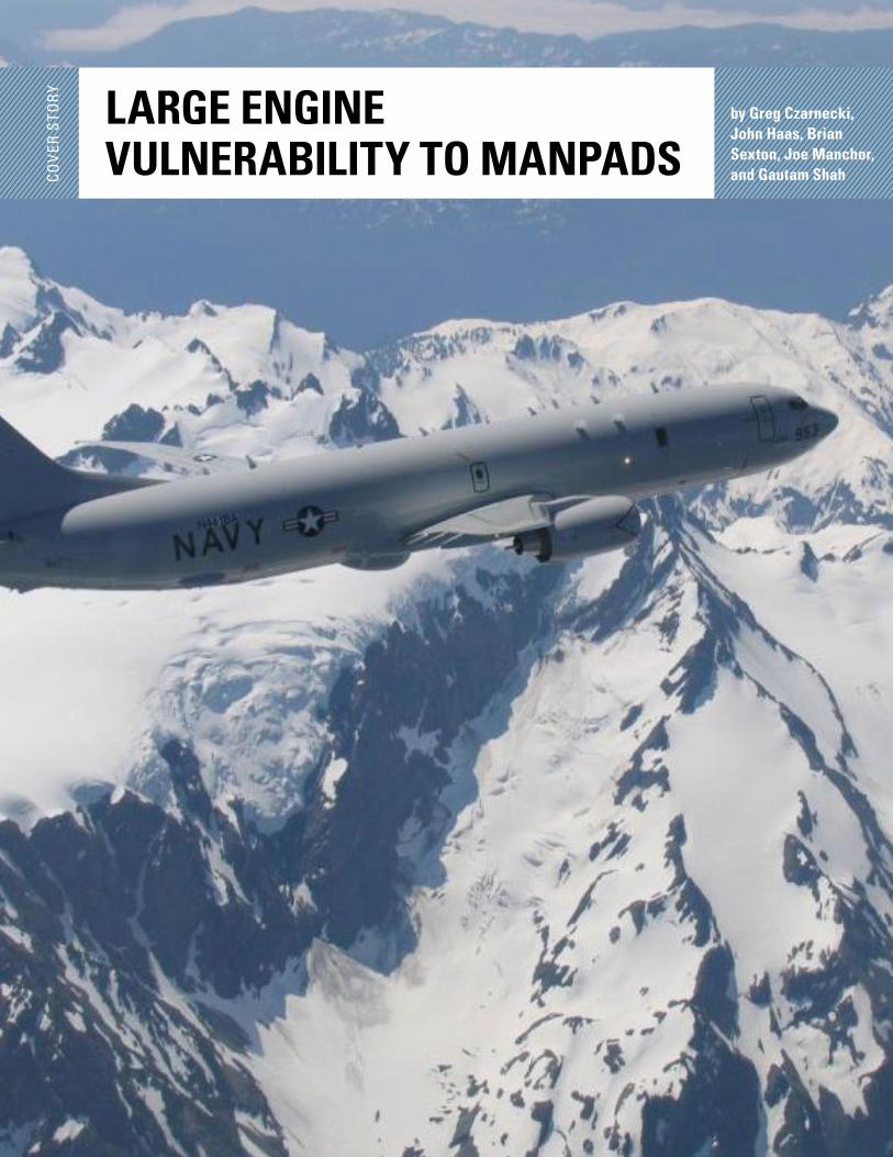
On the cover: Jacksonville, Fla. (Nov. 29, 2013) Aviation Electronics Technician 3rd Class Christopher Davis, assigned to Patrol Squadron (VP) 16, prepares to launch a P-8A Poseidon aircraft. VP-16 is the first operational squadron to deploy with the P-8A. (U.S. Navy photo by Mass Communication Specialist 2nd Class Eric A. Pastor/Released).
TABLE OF CONTENTS
4 NEWS NOTESby Dennis Lindell
5 JCAT CORNERby CAPT Cliff Burnette, Lt Col Douglas Jankovich, and CW5 Mike Apple
6 LARGE ENGINE VULNERABILITY TO MANPADSby Greg Czarnecki, John Haas, Brian Sexton, Joe Manchor, and Gautam Shah
This article summarizes an assessment of large aircraft engine vulnerability to the man-portable air defense system (MANPADS) missile threat. Testing and modeling involved MANPADS shots into operating/rotating CF6-50 engines, which are typical of large transport aircraft.
12 F135 PROPULSION SYSTEM LIVE FIRE TEST (LFT)by Charles Frankenberger
As part of the F-35 LFT Program, the LFT team recently conducted a series of LFTs to assess the Pratt & Whitney F135 propulsion system against ballistic damage. The F-35 LFT Master Plan includes a series of propulsion system tests designed to better understand the capabilities and vulnerabilities of the F135, once damaged, and to address assumptions used in the F-35 vulner-ability assessment.
15 EXCELLENCE IN SURVIVABILITY— DR. MARK ROBESONby Ken Branham
The Joint Aircraft Survivability Program (JASP) takes great honor in recognizing Dr. Mark Robeson for his outstanding contributions to combat aircraft advances, his leadership within JASP, and his Excellence in Survivability. Mark is an aerospace engineer at the US Army’s Aviation Development Directorate – Aviation Applied Technology Directorate (ADD–AATD) located at Joint Base Langley-Eustis, VA.
19 LESSONS LEARNED FROM LIVE FIRE TEST AND EVALUATION (LFT&E)by James O’Bryon
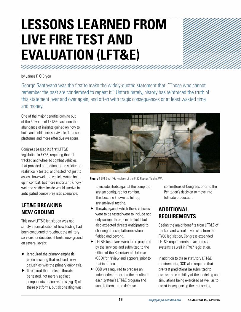
One of the major benefits coming out of the 30 years of LFT&E has been the abundance of insights gained on how to build and field more survivable defense platforms and more effective weapons.
Congress passed its first LFT&E legislation in FY86, requiring that all tracked and wheeled combat vehicles that provided protection to the soldier be realistically tested, and tested not just to assess how well the vehicle would hold up in combat, but more importantly, how well the soldiers inside would survive in anticipated combat-realistic scenarios.

http://jaspo.csd.disa.mil AS Journal 14 / SPRING
Mailing list additions, deletions, changes, and calendar items may be directed to:
SURVIAC Satellite Office 13200 Woodland Park Road Suite 6047 Herndon, VA 20171 Fax: 703/984-0756 Email: [email protected]
Promotional Director Jerri Limer
Creative Director Michelle Meehan
Art Director Karim Ramzy
Technical Editor Alexandra Sveum
Journal Design Donald Rowe
Illustrations, Cover Design, Layout Isma’il Rashada
Distribution Statement A: Approved for public release; distribution unlimited, as submitted under OSD/DOT&E Public Release Authorization 14-S-0997.
22 PT6A ENGINE VULNERABILITYby Brent Mills
Many Department of Defense (DOD) aircraft (e.g., A-29, C-12, RC-12, U-21, U-21C, PC-12, T-6, T-34C, T-44, DHC-6, and C-23) are used in theater for delivering small cargo shipments, gathering intelligence, providing training, and transporting VIPs. For these aircraft, which have limited protection from ballistic threats, little ballistic vulnerability data exists.
25 LIGHTWEIGHT INTEGRALLY ARMORED HELICOPTER FLOOR by Mark Robeson
United Technologies Research Center (UTRC), Sikorsky Aircraft Corporation (SAC), and the US Army’s Aviation Development Directorate (ADD) – Aviation Applied Technology Directorate (AATD), with additional funding from the Joint Aircraft Survivability Program Office (JASPO), developed and demonstrated an affordable, lightweight integrally armored helicopter floor. The floor was designed using the architecture of the Sikorsky H-60 platform, and was required to perform all of the functions of the current floor while also providing ballistic protection from a 7.62 mm ball threat.
29 AN OPTIMAL CONCEPTUAL DESIGN OF A MISSILE WARNING SYSTEM (MWS)by Yeondeog Koo and Jongmin Lee
This paper introduces an optimal conceptual design of a MWS that improves survivability of low speed aircrafts. The design is implemented by fusing data of both an ultraviolet (UV) sensor and a radar sensor. The proposed MWS system is able to detect threats of infrared (IR)-based man portable air defense system (MANPADS) as well as radar/laser-guided missiles and unguided rockets more effectively.
32 RASE EXPERIMENTS IMPROVE AIRCRAFT SURVIVABILITYby Dennis Duquette and Kevin Gross
“Five, Four, Three, Two, One, Fire!” In September 2013, the Fire Control Officer issued this command 811 times before shooting more than 10,900 rounds of ammunition during the Rotorcraft Aircraft Survivability Equipment (RASE) Experiment, a 12-day live fire venue. The RASE 2013 experiment was conducted at a remote test site at Weapons Survivability Laboratory (WSL), Naval Air Warfare Center Weapons Division (NAWCWD), China Lake, CA.
AS Journal 14 / SPRING http://jaspo.csd.disa.mil 4
NEWS NOTES by Dennis Lindell
KEITH JOCHUM
It is with great sadness that we announce the passing of Mr. Keith Jochum. Keith fought a long, valiant battle with cancer, passing on 1 June 2013. Keith’s constant smile and upbeat approach to management and life is sorely missed.
Keith came to the Air Force Research Laboratory, Flight Dynamics Directorate, Aircraft Survivability Branch, Vehicle Equipment Division, as a Major in the US Air Force in April 1995, and remained until March 1998. After his retirement from the Air Force on 31 March 1998, he transitioned to civilian life, but did not stay away long. He came back as the 46th Test Wing (now 96th Test Group), Aerospace Survivability and Safety Operating Location, Aerospace Vulnerability Survivability Facility (AVSF) operations and maintenance (O&M) contract manager in June 2001. In 2011, the Landing Gear Test Facility (LGTF) was rolled under the Eglin O&M contract, so Keith was charged with managing both facilities. Keith managed the AVSF test support for many of the joint live fire and live fire test & evaluation (LFT&E) programs. He ensured tests were completed in a timely and accurate manner. He was instrumental in many of
the AVSF improvements, including construction of the Range 3 Upper Test Platform, above ground storage tanks, installation of the 50-ton crane, major upgrades to the control room, and greatly improving the data acquisition and control systems. He was also the manager when the AVSF was included in BRAC 2005, and he ensured the seam-less transition of critical equipment to China Lake in support of Air Force LFT&E. Keith ensured that no Air Force test fidelity was lost due to lack of equipment, instrumentation, or data collection. Weapons systems tested during his tenure included the F-22, F-35 JSF, A-10, B-1B, C-130J, C-17, C-5, KC-46, Predator, CF-6 engines, and a host of new state-of-the-art aircraft vulnerability reduction suites and technologies.
Keith was a pleasure to work with and was the “behind-the-scenes” glue that kept the AVSF and LGTF facilities running smoothly, ensuring accurate data and timely test completion. His constant dedication to completing of the mission has contributed significantly to the well-being of our airmen and the survivability of our weapons systems.
BRL-CAD CONTRIBUTOR’S GUIDE PUBLISHED AT GOOGLE DOC CAMPIndividuals from the US Army Research Laboratory (ARL); Quantum Research International; the SURVICE Engineering Company; and open source contributors from Cameroon, India, and New Zealand were recently part of a seven-member BRL-CAD documentation team selected to participate in the 2013 Google Summer of Code Doc Camp at Google
Headquarters in Mountain View, CA, from 14–18 October 2013. The main purpose of the camp, which was sponsored and hosted by Google’s Open Source Programs Office and FLOSS Manuals, was to plan and conduct a “Doc Sprint.” Doc Sprints are a unique approach to collaboratively plan, write, and publish a complete user’s manual in less than a week. BRL-CAD was one of three software projects selected to participate in this year’s sprints.
The camp’s 20 participant “sprinters” came from eight different countries. The manual the BRL-CAD team produced, titled HACKING BRL-CAD: A Contributor’s Guide, is primarily targeted at attracting and assisting new BRL-CAD developers and documenters in the open source community. Included are sections on working with code, contributing needed documentation, and performing other types of support tasks. Code snippets are also included to demonstrate several common BRL-CAD operations.

5 http://jaspo.csd.disa.mil AS Journal 14 / SPRING
BRL-CAD is a solid modeling package (and Survivability/Vulnerability Information Analysis Center [SURVIAC] product) developed by ARL more than 30 years ago and used throughout the tri-service community to create geomet-ric target descriptions and assist in vulnerability analyses. In addition, the package has been an open source project since 2004, receiving development assistance from contributors around the world. It was recently cited as being the oldest, continuously developed open source repository in existence.
To view the online version of HACKING BRL-CAD: A Contributor’s Guide, visit http://en.flossmanuals.net/contributors-guide-to-brl-cad/. For more information about the 2013 Google Doc Camp, visit http://www.booksprintsnet/2013/10/2013- google-doc-camp-done/.
THREAT WEAPONS EFFECTS TRAINING 2014The 2014 Threat Weapons Effects Training will take place on Hurlburt Field and Eglin Air Force Base, FL from 22–24 April, 2014.
Conflicts and threats have highlighted the need for the survivability of our aircraft and force protection of our soldiers. This training will address issues related to the lethality of enemy weapon systems from small caliber munitions to anti-aircraft missiles within the broad considerations of system design and employment. This annual training is a collaborative effort between the Joint Combat Assessment Team (sponsored by the Joint Aircraft Survivability Program Office), the Army Research Laboratory, Naval Air Systems Command, Air Force Aeronautical Systems Center, the Missile and Space Intelligence Center, National Ground Intelligence Center, and other agencies. The training draws information from threat exploitation, live fire testing, and
combat experience to provide a complete picture on threat lethality. This training provides hands-on experience with threat munitions/missiles, test articles, and damaged aircraft. Experienced professionals provide current, relevant information on threat system upgrades, proliferation, and lethality.
The following are encouraged to attend: aviation operations personnel, intelligence professionals, weaponeering staff, individuals involved with battle damage and repair, US government and industry executives, survivability engineers, and research, development, test, and evaluation professionals. Anyone with an interest in threat weapons, intelligence, or aviation survivability is welcome. The training will be held at the SECRET/NOFORN level.
JCAT CORNERby CAPT Cliff Burnette, Lt Col Douglas Jankovich, and CW5 Mike Apple
NAVY JCATThe Naval Air Systems Command (NAVAIR) Reserve In-Service Engineering & Logistics, Detachment B (ISEL Det B) established the Joint Combat Assessment Team (JCAT) Forensic Training Range (JCAT Range). The JCAT Range is a 350 acre site that will allow
ISEL Det B to simulate combat conditions for the Phase II course. Instructor cadre will stage several scenarios based on real-world events that JCAT has assessed in the last 10 years. The training sites will feature widely scat-tered debris, missing pieces, post-crash fire, night versus day, and hostile crash
sites to better prepare our teams as they go forward. When fully completed, the JCAT Range will provide a training area to better prepare JCAT assessors for the rigors of conducting an assessment outside the wire in remote, rugged, and hostile environments. Staging of downed
continued on page 17
Figure 1 BRL-CAD Doc Sprint Team Figure 2 BRL-CAD Doc Sprint Team
AS Journal 14 / SPRING http://jaspo.csd.disa.mil 6
LARGE ENGINE VULNERABILITY TO MANPADSCO
VER
STO
RY
by Greg Czarnecki, John Haas, Brian Sexton, Joe Manchor, and Gautam Shah

7 http://jaspo.csd.disa.mil AS Journal 14 / SPRING
This article summarizes an assessment of large aircraft engine vulnerability to the man-portable air defense system (MANPADS) missile threat. Testing and modeling involved MANPADS shots into operating/rotating CF6-50 engines, which are typical of large transport aircraft.
MANPADS missiles represent a significant threat to both civil and military aviation. Large wide-body military and commercial transport aircraft continue to be attractive targets and are particularly susceptible to MANPADS during takeoff and landing due to large infrared emissions, slow speeds, predictable flight paths, unencrypted air traffic communications, and publicly available commercial schedules. Recent events raised the level of awareness and the desire to find ways to counter this missile threat (see Figure 1).
An important first step in making investment decisions—involving large aircraft susceptibility and vulnerability reduction measures necessary to counter the MANPADS threat—is to understand and determine the likely outcome of a MANPADS missile encounter. Analysis and combat data reveal that the most likely impact point for a MANPADS is on an aircraft’s engine; however, the level of damage and the potential for collateral effects leading to aircraft loss was unclear. Given an engine hit, the aircraft survivability community needed to understand the extent of propulsion system damage and the likelihood of engine uncontainment, collateral damage, and sustained fire.
APPROACHThe Joint Live Fire (JLF) - Aircraft Systems, Department of Homeland Security (DHS), Air Force Life Cycle Management Center (AFLCMC), 96th Test Group (96 TG), Naval Air Warfare Center (NAWC), National Aeronautics and Space Administration (NASA), and General Electric Aircraft Engines (GEAE)
collaborated to assess MANPADS damage effects on a large transport aircraft engine. GEAE’s CF6-50 turbofan engine (see Figure 2), in combination with a Boeing B747 nacelle and outboard pylon, were test assets for the current investigation. Selection was based on test asset relevancy and availability. MANPADS missile selection was based on a combination of worldwide prolifera-tion, missile hardware availability, missile model availability, availability of some engine-damage predictions using this threat, and the proven ability to launch this missile in a precisely controlled manner for the test.
The effort consisted of combined modeling and testing, and began with hardware-in-the-loop simulations (performed by the 96 TG Wing’s Guided Weapons Evaluation Facility) to identify possible missile approach directions and impact locations as a function of aircraft flight scenario. Based on simulation results, JLF, DHS, the Institute for Defense Analysis, AFLCMC, and the 96 TG collaborated on selecting of shotlines
and hit points, as well as the test scope. Two shotlines were selected, each involving missile intersection of rotating engine parts. Shotline #1 (Test #1 on operating Engine #1) selection assumed a likely outcome of moderate engine damage and limited collateral damage. Shotline #2 (Test #2 on operating Engine #2) selection assumed a likely outcome of substantial engine damage with wide-ranging collateral damage.
After the team defined shotlines and hit points, GEAE (under contract with the 96 TG and with co-funding from Joint Aircraft Survivability Program [JASP] and AFLCMC) generated damage predictions for each planned impact location. Using a high-fidelity MANPADS missile model developed by RHAMM Technologies, GEAE created an engine versus MANPADS modeling procedure with the LS-DYNA finite element modeling code. GEAE applied this modeling process to generate damage predictions for live and inert MANPADS impacts on operating and non-operating CF6-50 engines. By virtue of merging a fully functional missile
Figure 1 Example Outcome of MANPADS Encounter with Commercial Aircraft

AS Journal 14 / SPRING http://jaspo.csd.disa.mil 8
model with a counter-rotating engine model and having sufficient fidelity in each model to yield credible damage predictions, this was not only a first-ever for the aircraft vulnerability assessment community, but also one of the most complex modeling endeavors ever attempted. Damage predictions for Test #1 proved in line with original expecta-tions, suggesting limited uncontained engine debris (mostly turbine blades) and collateral damage. Conversely, damage predictions for Test #2 were not aligned with original expectations of substantial engine damage. Instead, Test #2 predictions showed reduced damage levels based on shotline nuances. Nevertheless, because of the investment in damage predictions, the test team agreed to proceed as planned.
Formal predictions of fire were not prepared. Instead, the test team used engineering judgment and predicted a high likelihood of fires given high-speed missile hits on hot engine components containing numerous pressurized flammable fluid lines. A remaining question, whether fire might endanger aircraft safety-of-flight, was resolved through a combination of testing and post-test analysis.
TEST SUMMARYThe 96th Test Group’s Aerospace Survivability and Safety Operating Location (96 TG/OL-AC) at Wright-Patterson Air Force Base (WPAFB), OH prepared the CF6-50 engines for test. Preparations included acquiring and
assembling all necessary engine, nacelle, and pylon elements of the test articles; designing and fabricating the steel load-reaction fixture; instrumenting the test articles and load-reaction fixture; preparing control algorithms for remote engine operation; and, with GEAE’s assistance, verifying engine and instru-mentation operation. Prior to declaring readiness for testing, the 96 TG and GEAE conducted engine pretests that included dry motoring, wet motoring, ground idle, and flight idle. All engine serviceability and controllability issues were corrected on the spot at WPAFB before shipping the engines and load-reaction fixture to the NAWC Weapons Division’s Weapon Survivability Laboratory at China Lake, CA for full-up testing.
NAWC installed the load-reaction fixture and engines on their live fire test pad. As was done at WPAFB, GEAE assisted with a series of pretests leading up to each test-for-score. Pretests began with dry/wet motoring and ground/flight idle speeds, and then extended to greater measures of engine thrust, first without airflow and then with external airflow applied. NAWC’s Super High Velocity Airflow System (SHiVAS) generated external airflow over the CF6 engines and pylon. NAWC’s Missile Engagement Threat Simulator (METS) was used to precisely control the missile’s shotline, impact velocity, hit-point, and detonation delay for 1:1 correspondence with modeled conditions.
Figure 3 displays the airflow from NAWC’s nine-engine SHiVAS facility (upper right) and how it is ducted into the CF6-50 engine mounted on the load-reaction fixture (upper left). The METS Missile Launcher is in the center-foreground.
Under direction and assistance of the 96 TG, NAWC performed successful MANPADS shots into the two CF6-50 engine test articles. In each test, the missile shotline angle, impact velocity, hit-point, and detonation location correlated to modeled conditions within a few feet per second, fractions of a degree, and fraction of an inch, respec-tively. This degree of test control was necessary for direct correlation between test and model outcomes. Additionally, this degree of test control was essential to test success. Not only did the missile have to exit the METS launcher flaw-lessly (to include separation of the pusher sabot), but the missile had to maintain its predicted path over 50 feet of travel, enter the engine thrust flow-field, pass through a powered ring just slightly greater than the missiles diameter, and then hit the engine at a pre-designated point. As can be seen in Figure 4, there was no margin for error. With little more than an inch clearance, the missile had to pass through a powered ring (left-center) and detonate on queue to ensure a successful test. Gridded witness plates were positioned above and beside the engine to score uncontained engine debris that might lead to collateral damage. Any miscalculation (to include accounting for solar heating of the METS barrel) would have resulted in a failed test, possibly with the missile hitting and destroying itself on the powered ring fixture, then the debris field flying into and destroying the engine.
Figure 2 GEAE Model of the CF6-50 Engine Figure 3 SHiVAS and METS

9 http://jaspo.csd.disa.mil AS Journal 14 / SPRING
Instrumentation data were collected for both tests and provided a good indication of loads and accelerations experienced by the engine and pylon mounts. Key engine data monitored and recorded during the test included engine rotation rates, such as N1 (fan, low pressure compressor, and low pressure turbine) and N2 (high pressure compressor and high pressure turbine), and engine temperatures, such as compressor inlet temperatures, turbine intake tempera-tures, and exhaust gas temperatures. Other key data elements included strains along key load-paths (to assess missile-generated loads transferred through the pylon); blast-induced pressures within the engine-core; accelerometers to assess engine vibration; high-speed video of the impact event (to verify correct missile position and function); and post-test quantification of the damage (for direct correlation with modeled pretest damage predictions and for transition to NASA for the safety-of-flight assessment). High-speed cameras provided excellent views of missile impact and detonation.
POST-TEST ANALYSES Engine damage conditions and expecta-tions for collateral damage were provided to NASA Langley researchers for a final round of modeling and simulation. This work involved post-test aerodynamic modeling of the aircraft’s damage state to assess controllability and safety-of-flight implications. Analyses spanned
several damage scenarios—those directly recorded in the tests to those that were assumed based on collateral damage estimations. NASA modeling and simulation began by measuring changes to aerodynamic characteristics as a function of damage location and damage magnitude. For this task, NASA used data from tests of their Generic Transport Model configuration, where they removed potential damaged elements from the airframe, and “flew” the damaged model within a wind tunnel (see Figure 5). Wind tunnel tests measured and modeled changes to the aerodynam-ics as a function of degraded engine thrust and estimated collateral damage on the airframe. Measured changes to the aircraft’s aerodynamics then were applied to the NASA flight simulator. While flying the generic transport aircraft simulation, NASA research pilots and engineers had to react to aircraft stability and control characteristics that abruptly changed (accounting for various damage states). Pilots had to maintain control of the aircraft, evaluate controllability characteristics, and then attempt a safe landing. Pilot control inputs and aircraft responses were recorded and supple-mented by post-flight debriefings. Within the NASA flight simulator, pilots reacted to the aircraft’s sudden change of state and determined courses of action necessary to achieve safe landings (see Figure 6).
CONCLUSIONSData produced by these tests demonstrated credibility of the high-fidelity engine-MANPADS modeling procedure developed by GEAE. Test results correlated closely with damage predictions. This judgment is based on comparing the final damage state to the LS-DYNA predictions coupled with engineering judgments for how the damage would propagate over the remainder of the test. Based on combined test and model results, pilots should be aware of and ready for situations in which they are simultaneously presented with a loss of thrust, an engine fire, and degraded flight control.
The combined model-test-model engine-MANPADS effort represented a cost effective and low-risk method of determining the likely outcome of a MANPADS incident. The overall effort completes a first look at MANPADS damage effects on operating engines and the outcome on aircraft safety-of-flight. Such information will prove valuable to decision makers charged with operational risk assessments and the development of counter-MANPADS technologies.
ACKNOWLEDGEMENTSWork was co-funded by, and received guidance from, the Department of Defense’s Director, Operational Test and Evaluation’s (DOT&E’s) JLF Program,
Figure 4 No Margin for Error – METS Missile Launcher
Figure 5 Generic Transport Aircraft Model in the NASA 14x22 Wind Tunnel
Figure 6 NASA Flight Simulator
AS Journal 14 / SPRING http://jaspo.csd.disa.mil 10
DHS’s Counter-MANPADS Program, and the USAF’s Large Commercial Derivative Aircraft Program. In addition, the effort received supplemental funding from NASA and JASP.
Authors of the current article are a small fraction of the diverse and talented team that together achieved test and modeling goals within this large engine vulnerabil-ity to MANPADS effort. Authors thank the following individuals and organiza-tions for their contributions:
� DHS—Kerry Wilson for taking the risk of investment in this first-ever and highly complex engine-MAN-PADS test effort. Alex Estorga, Michael Paul, and Thanh Luu for expert guidance during test planning, shotline selection, and test execution.
� JLF and DOT&E—Robert Lyons and Rick Seymour for taking the risk of co-investing in this test effort and for guidance/direction that ensured test success. Their investment (in combination with that from DHS) ensured completion of the two full-up engine-MANPADS tests.
� AFLCMC—John Funk and Gene Gregory for taking the risk of co-investing in this test effort. Their investment enabled a test and modeling support contract with GEAE, where GEAE’s support later proved essential to ensuring engine operation and achieving test success.
� NASA—Christine Belcastro and John Carter for sharing the engine-MANPADS test and evaluation vision as early as 2004 and for securing funds necessary to acquire engine test assets.
� JASP—Dennis Lindell and Ken Branham for behind-the-scenes test support.
� Joint Combat Assessment Team—Major Scott Quackenbush for assisting with post-test forensics at the test site.
� NAWC—Jay Kovar, Albert Bermudez, Jimmy Johns, Ronnie Schiller, Will Heermann, Mike O’Connell, and Chuck Frankenberger for accepting and minimizing test-risk associated with this first-ever and highly complex test effort. Albert Bermudez for assisting with coordi-nating and guiding of the overall NAWC test-support effort, and for ensuring test success at NAWC’s premier test facility. Ronnie Schiller and Mark Metelko for their inputs in design iterations of the engine support structure and the structure’s ability to tie into the test pad. Will Heermann for help mitigating acoustic problems associated with running 10 jet engines simultaneously and in close approximation; also for resolving software and hardware requirements in a timely manner. Gary Ahr for helping with instrumentation and overall test support.
� METI—Matt Matthews and the entire METI team for hands-on support during test setup and execution. Ray Hocker and Gary Brown for their attention to detail and continued interaction with the test engineer to ensure capture of optimal video photography during the tests. Wes Witt and Bruce Thompson for their help with pad setup and test article preparation. Together, this METI team maintained a professional can-do attitude during long hours and less than ideal weather conditions. METI was instrumental to test success.
� InDyne—Jason Sawdy and Rob Crosby for coordinating and guiding the overall InDyne test-support effort to include identifying and economi-cally acquiring engine, cowling, and
pylon test assets; overseeing the test fixture design/fabrication effort; and ensuring all test assets were delivered to the China Lake test site well in advance of planned tests. Mike Palumbo for conceptually designing the engine support fixture and then iterating the design based on inputs from finite element modelers and from NAWC. Jake Wiggins for designing and implement-ing a test instrumentation setup that allowed for easy installation into the range, troubleshooting, and docu-menting the report. Jared Hilgeman for assisting with reviving the CF6-50 engines from the as-purchased state to a fully functional state and for hands-on assistance with a smile throughout testing at China Lake.
� RHAMM—Ron Hinrichsen, Steve Stratton, Brian Barlow, and Steve Rosencrantz for developing and tuning the MANPADS missile model for GEAE implementation. Steve Stratton for generating, running, and analyzing countless design iterations of the engine support structure to ensure adequate factors of safety were in place for the highly dynamic test conditions.
� Skyward—Dan Cyphers for his detailed test plan reviews, on-site data collection support, and early-on behind the scenes interactions that helped secure project investors. Ralph Lauzze for his broad background of experience that helped with test plan development, and Ralph Speelman for guidance with articulation of an engine-MANPADS assessment vision enthusiastically adopted by team members.
� GEAE—Gary Wollenweber and Danny Jones for helping to coordinate and guide the overall GEAE support effort. Tom Beck and Jim Orth for guidance and assistance with getting CF6-50 engine test assets ready for
11 http://jaspo.csd.disa.mil AS Journal 14 / SPRING
test, preparing the script necessary for engine operation during test, being present during every engine run to ensure correct engine function, candidly making real-time test readiness assessments and recom-mendations to the government test engineer, and for assessing the extent of engine damage after each test. Sunil Sinha for accepting the exceptional technical risk of develop-ing a first-ever engine-MANPADS modeling procedure and for success-fully implementing the procedure to produce useful and credible engine damage predictions.
� Institute for Defense Analyses—Joel Williamsen, Mark Couch, and Al Wearner for guidance and advice during test planning and test execution.
References
[1] In addition to the B747, the CF6-50 is common to McDonnell Douglas KC-10 and Airbus A300 aircraft. Advanced derivatives of the CF6-50 are also found on the Lockheed C-5, Boeing B767, and other aircraft.
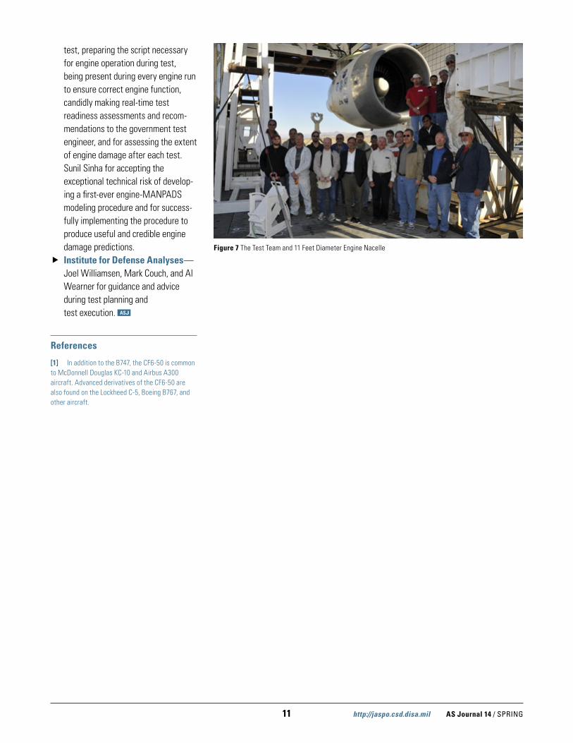
Figure 7 The Test Team and 11 Feet Diameter Engine Nacelle

AS Journal 14 / SPRING http://jaspo.csd.disa.mil 12
All testing was conducted at the Weapon Survivability Laboratory (WSL) in China Lake, CA. Testing was conducted by personnel from the WSL; Pratt and Whitney; Hamilton Sundstrand; Lockheed Martin; Director, Operational Test and Evaluation; and the Institute for Defense Analysis.
F135 PROPULSION SYSTEMThe F-35B STOVL variant combines unique engineering technologies in a fighter engine. The F-35B uses a single F135 main engine coupled with a lift fan and roll posts to provide STOVL capabil-ity. Differences between the conventional takeoff and landing (CTOL) and STOVL propulsion system include the straight augmenter duct versus the 3 bearing swivel module (3BSM), and the addition of the lift fan shaft, clutch and lift fan, roll posts, and a lift fan vane box (see Figure 1). The F135 main engine and
lift system together work to provide veritcal thrust and attitude control for the F-35B aircraft.
TEST SCENARIOF135 ballistic testing was conducted to assess the engine’s steady state and transient performance after damage. Testing was conducted at part power and Military (MIL) power conditions. Data
was collected to monitor the control system reaction, transient performance, and resultant steady state performance. Engine stability checks were then performed by slowly increasing and decreasing the throttle from part power to MIL power. The engine’s operability was assessed using snaps from Idle power setting (IDLE) to MIL, and chops from MIL to IDLE.
OCCUPANT CASUALTY M&Sby Charles Frankenberger
As part of the F-35 LFT Program, the LFT team recently conducted a series of LFTs to assess the Pratt & Whitney F135 propulsion system against ballistic damage. The F-35 LFT Master Plan includes a series of propulsion system tests designed to better understand the capabilities and vulnerabilities of the F135, once damaged, and to address assumptions used in the F-35 vulnerability assessment. Three F135 test series were conducted:
�Short Takeoff and Vertical Landing (STOVL) Propulsion System Test—Designed to address the unique aspects of the F135 propulsion system, specifically related to the STOVL capability. �Engine Ballistic Test—Aimed at better understanding the advance engine control system and the capabilities of the main engine with gas path damage. �Fuel Ingestion Test—Conducted to assess the engine’s fuel ingestion tolerance.
F135 PROPULSION SYSTEM LIVE FIRE TEST (LFT)
CTOL/CV
STOVL
Diverterless Supersonic Inlet• Full Obscuration of
Engine Face• No Bleed, Bypass,
or Diverter
• Classic Fighter Integration• Rearward Installation and Removal• Excellent Transient Response
Conventional Axial Duct
LOAN Nozzle• High Internal Performance• Low External Drag
3BSMCommonTurbomachinery
Auxiliary Inlet
Lift Fan• Two-Stage Fan• Counter-Rotating• Low Pressure Ratio
Clutch
DriveshaftRoll Posts
Figure 1 STOVL Propulsion System Components
13 http://jaspo.csd.disa.mil AS Journal 14 / SPRING
The STOVL propulsion system test required additional consideration of the mission scenario to define the test conditions. The majority of an F-35B mission is spent in the up-and-away, wing-born mode (i.e., flying as a conven-tional aircraft where the wings are providing the lift); therefore, it follows that most of the flying and fighting will be done in the up-and-away mode. In this mode, the lift fan is static, the lift fan clutch is disengaged, 3BSM is horizontal, and the roll post nozzles are closed. Ballistic testing was conducted with the propulsion system in the up-and-away mode. Then, with the system in a damaged state, the propulsion system was commanded to transition from wing-born to jet-born propulsion mode. If the transition was successful, a vertical landing script was run to assess the STOVL propulsion system capability during the vertical landing scenario.
A few key issues to be answered were:
� Is the damage catastrophic? � Is the systems residual capability
sufficient to allow the aircraft to return to base?
� Does the control system alert the pilot of the reduced capability?
For the STOVL system, two additional issues were:
� Can the system safely transition to jet-born mode?
� Is the residual capability sufficient to conduct a vertical landing?
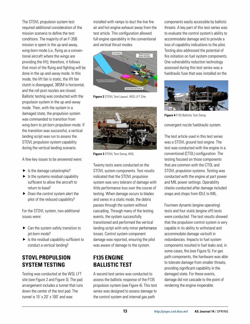
STOVL PROPULSION SYSTEM TESTINGTesting was conducted at the WSL LFT site (see Figure 2 and Figure 3). The pad arrangement includes a tunnel that runs down the center of the test pad. The tunnel is 15’ x 20’ x 100’ and was
installed with ramps to duct the live fire air and hot engine exhaust away from the test article. This configuration allowed full engine operability in the conventional and vertical thrust modes.
Twenty tests were conducted on the STOVL system components. Test results indicated that the STOVL propulsion system was very tolerant of damage with little performance loss over the course of testing. When damage occurs to blades and vanes in a static mode, the debris passes through the system without cascading. Through many of the testing events, the system successfully transitioned and performed the vertical landing script with only minor performance losses. Control system component damage was reported, ensuring the pilot was aware of damage to the system.
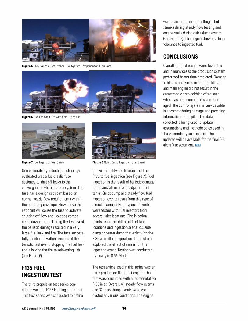
F135 ENGINE BALLISTIC TEST A second test series was conducted to assess the ballistic response of the F135 propulsion system (see Figure 4). This test series was designed to assess damage to the control system and internal gas path
components easily accessible by ballistic threats. A key part of this test series was to evaluate the control system’s ability to accommodate damage and to provide a loss of capability indications to the pilot. Testing also addressed the potential of fire initiation on fuel system components. One vulnerability reduction technology assessed during this test series was a fueldraulic fuse that was installed on the
convergent nozzle fueldraulic system.
The test article used in this test series was a STOVL ground test engine. The test was conducted with the engine in a conventional (CTOL) configuration. The testing focused on those components that are common with the CTOL and STOVL propulsion systems. Testing was conducted with the engine at part power and MIL power settings. Operability checks conducted after damage included snaps and chops from IDLE to MIL.
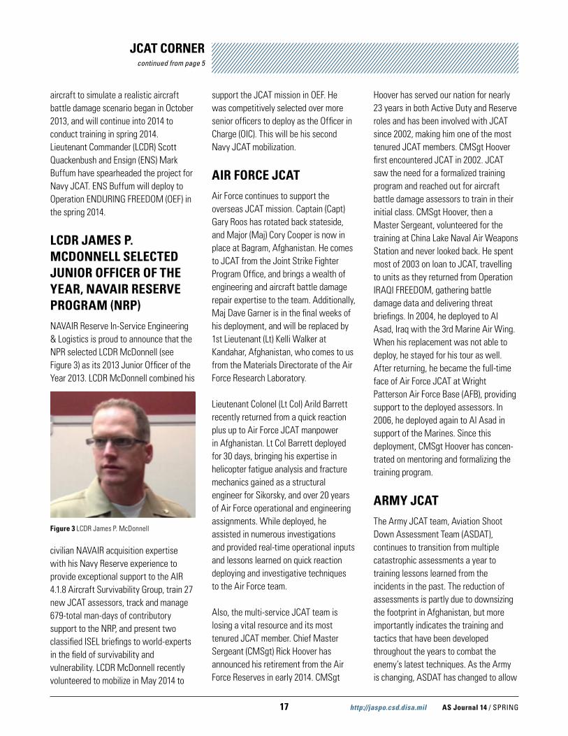
Fourteen dynamic (engine operating) tests and four static (engine off) tests were conducted. The test results showed that the propulsion control system is very capable in its ability to withstand and accommodate damage via built in redundancies. Impacts to fuel system components resulted in fuel leaks and, in some cases, fire (see Figure 5). For gas path components, the hardware was able to tolerate damage from smaller threats, providing significant capability in the damaged state. For these events, damage did not cascade to the point of rendering the engine inoperable.
Test PlatformSTOVL Propulsion System Test Stand
Tunnel Under Test Platform
Test Platform Partially Removed to Expose Tunnel and Defectors
Figure 2 STOVL Test Layout, WSL LFT Site
Figure 3 STOVL Test Setup, WSL
Figure 4 F135 Ballistic Test Setup
AS Journal 14 / SPRING http://jaspo.csd.disa.mil 14
One vulnerability reduction technology evaluated was a fueldraulic fuse designed to shut off leaks to the convergent nozzle actuation system. The fuse has a design set point based on normal nozzle flow requirements within the operating envelope. Flow above the set point will cause the fuse to activate, shutting off flow and isolating compo-nents downstream. During the test event, the ballistic damage resulted in a very large fuel leak and fire. The fuse success-fully functioned within seconds of the ballistic test event, stopping the fuel leak and allowing the fire to self-extinguish (see Figure 6).
F135 FUEL INGESTION TESTThe third propulsion test series con-ducted was the F135 Fuel Ingestion Test. This test series was conducted to define
the vulnerability and tolerance of the F135 to fuel ingestion (see Figure 7). Fuel ingestion is the result of ballistic damage to the aircraft inlet with adjacent fuel tanks. Quick dump and steady flow fuel ingestion events result from this type of aircraft damage. Both types of events were tested with fuel injectors from several inlet locations. The injection points represent different fuel tank locations and ingestion scenarios, side dump or center dump that exist with the F-35 aircraft configuration. The test also explored the effect of ram air on the ingestion event. Testing was conducted statically to 0.66 Mach.
The test article used in this series was an early production flight test engine. The test was conducted with a representative F-35 inlet. Overall, 41 steady flow events and 32 quick dump events were con-ducted at various conditions. The engine
was taken to its limit, resulting in hot streaks during steady flow testing and engine stalls during quick dump events (see Figure 8). The engine showed a high tolerance to ingested fuel.
CONCLUSIONSOverall, the test results were favorable and in many cases the propulsion system performed better than predicted. Damage to blades and vanes in both the lift fan and main engine did not result in the catastrophic corn-cobbing often seen when gas path components are dam-aged. The control system is very capable in accommodating damage and providing information to the pilot. The data collected is being used to update assumptions and methodologies used in the vulnerability assessment. These updates will be available for the final F-35 aircraft assessment.
Figure 5 F135 Ballistic Test Events (Fuel System Component and Fan Case)
Figure 6 Fuel Leak and Fire with Self-Extinguish
Figure 7 Fuel Ingestion Test Setup Figure 8 Quick Dump Ingestion, Stall Event

15 http://jaspo.csd.disa.mil AS Journal 14 / SPRING
Mark began his career in the research of advanced composite aircraft structures as a graduate student at
National Aeronautics and Space Administration (NASA) Langley Research Center (LaRC) in 1990. He stayed at NASA after graduation as a National Research Council Post-Doctoral Fellow, accepting his current position with ADD–AATD in 2000. Mark is a technical specialist in the structures technical area, planning, coordinating, and executing aviation science and technology efforts as part of an integrated strategy to support research, development, test, and evaluation. His research efforts have supported all current and future Army aviation systems. He has led multiple complex, multi-million-dollar, multi-faceted technology development efforts. Several of his most significant efforts in the survivability arena include:
� Electrical Attenuating Core Structures (EACS)—The objective of EACS was to develop a radar absorbing structure based on the X-Cor structural sandwich core configuration.
� Pultruded Lightweight Integral Rotorcraft Armor (PLIRA)—The objective of PLIRA was to develop low-cost structural aircraft armor.
� High Strain-Rate Modeling and Conductivity for Composite Structures (HSMCCS)—The objective of HSMCCS was to• Develop and validate improved
high strain-rate modeling capability for highly loaded structural fittings, energy absorbing composite structures, and ballistic penetration of composite laminates
• Demonstrate the effectiveness of lightning strike protection appliqué for rotorcraft primary composite structure and anten-nae/radomes
• Develop and demonstrate a conformal, broad-spectrum antenna, structurally integrated into primary composite structure
� Integrally Armored Floor (IAF) and Lightweight Integrally Armored Floor (LIAF)—The objectives of IAF and LIAF were to develop and demonstrate affordable multifunctional integral armor solutions for a helicopter floor that provide 7.62 x 39 mm ballistic protection (armor piercing for IAF, ball for LIAF) at reduced weight, as compared to current technology.
� Integrated Aircraft & Crew Protection (IACP)—The objective of IACP was to select technology to enhance aircraft / occupant protec-tion, improve durability, and reduce environmental vulnerability, as well as to define a technology maturation and demonstration approach for a follow-on technology demonstration.
� Blast Attenuating Aircraft Structure (BAAS)—The objective of BAAS is to develop and mature a durable structural sandwich core concept to efficiently mitigate the
EXCELLENCE IN SURVIVABILITYDR. MARK ROBESON
by Ken Branham
The Joint Aircraft Survivability Program (JASP) takes great honor in recognizing Dr. Mark Robeson for his outstanding contributions to combat aircraft advances, his leadership within JASP, and his Excellence in Survivability. Mark is an aerospace engineer at the US Army’s Aviation Development Directorate – Aviation Applied Technology Directorate (ADD–AATD) located at Joint Base Langley-Eustis, VA. His areas of specialization are advanced composite airframe structures, structural contribu-tions to vulnerability reduction, multifunctional structures, and structural airworthiness—all with a primary focus on rotorcraft. Mark has accumulated over 23 years of research and development experi-ence with advanced aircraft structures, and holds multiple degrees including an MS (1992) and PhD (1998) in engineering mechanics—both awarded by Old Dominion University.

AS Journal 14 / SPRING http://jaspo.csd.disa.mil 16
effects of blast overpressure on enclosed volumes representative of rotorcraft structures.
� Hydraulic Ram Compliant Structure (HRCS)—The objective of HRCS is to develop and mature durable structural concepts to efficiently mitigate hydrodynamic ram effects on rotorcraft structures due to ballistic and crash events.
� Combat Tempered Aft Fuselage (CTAF)—The objective of CTAF is to develop, mature, and demonstrate primary rotorcraft structures that enhance operational durability and damage tolerance (including tolerance of high-energy ballistic threats), focusing on the composite tail boom (CTB) targeted for insertion on the Apache aircraft (AH-64).
Mark has been a key part of the joint multi-role (JMR) technology demonstra-tion efforts, advising JMR leadership on structures and vulnerability reduction topics that drive the survivability requirements. JMR aircraft technology will serve the soldier for decades in the future. As a recognized structures expert, Mark serves on various standing and temporary safety of flight review boards, advising airworthiness authorities on issues related to rotary-wing and fixed-wing aircraft systems. To date, he has signed findings documents for over 450 airworthiness releases. Mark has planned, budgeted, scheduled, and executed multiple complex structural testing programs, including the rotary wing structure technology demonstration, which was a Sikorsky structural testing effort.
Serving as the Structures & Materials Committee co-chair for the JASP Vulnerability Reduction Subgroup, Mark is an integral member of the JASP survivability community. His expertise and knowledge are highly valued when
evaluating the technical merit of proposals, and providing recommenda-tions on the establishment of JASP funding priorities. He is constantly sought to participate with other JASP projects, such as “Thermal Degradation of Composites” and “Laser Weapon Effects on Aircraft Materials,” demonstrating his breadth of knowledge and professional acumen. He is also a leader in the JASP Crew and Passenger Survivability effort and briefed at the Technology workshop. As the go-to guy in JASP for giving impressive and articulate briefings, Mark has been invited to present at numerous JASP meetings.
Staying engaged in a multitude of professional organizations outside of the Army, Mark has and continues to be thoroughly involved in the local and national rotary-wing engineering community. He has been an American Helicopter Society (AHS) member since 2000, serving as the Hampton Roads Chapter (HRC) Vice President / Program Chairman in 2006 and President in 2007. He is currently a member of two AHS technical committees: Structures & Materials and Aircraft Design. Mark has been a member of the Army Aviation Association of America since 2000, the American Institute of Aeronautics & Astronautics since 1990 (currently a Senior Member), and the American Society of Mechanical Engineers since 1990.
Mark has authored and peer-reviewed journal articles, numerous ADD–AATD technical reports, and a multitude of conference papers. His professional accomplishments have been appropri-ately recognized by his peers and include the 2002 Department of the Army Commendation (Hellfire Missile Debris Deflector design and test efforts); 2004 AHS Robert L. Pinckney Award (Complex Composite Structural Concepts Team
efforts); 2012 JASP Engineer of the Year Award; 2013 AHS Harry T. Jensen Award (AH-64 CTB Team efforts); 2013 AHS–HRC John White Engineer of the Year Award (career accomplishments and community involvement); and numerous ADD–AATD Commander’s Award nominations.
Mark is the epitome of the strong family man and anchored in his church. He attended high school in Yorktown, VA at Tabb High School, and married his high school sweetheart, the former Paula Thomas. They have been married for 22 years. Mark spends much of his free time with his son, Luke (10), and daughter, Sarah (14), helping out with homework and attending their sporting events, like basketball and volleyball. He has served on his Homeowners’ Association Board of Directors for the past several years. Mark and Paula are also involved in several aspects of their church, where Mark serves as a Deacon. Recreationally, Mark still enjoys shooting, having participated in competitive rifle marksmanship throughout high school.
It is with great pleasure that JASP recognizes Dr. Mark Robeson for his Excellence in Survivability for his contributions to the survivability disci-pline, aircraft community, and the soldier. Well done!
17 http://jaspo.csd.disa.mil AS Journal 14 / SPRING
JCAT CORNERcontinued from page 5
aircraft to simulate a realistic aircraft battle damage scenario began in October 2013, and will continue into 2014 to conduct training in spring 2014. Lieutenant Commander (LCDR) Scott Quackenbush and Ensign (ENS) Mark Buffum have spearheaded the project for Navy JCAT. ENS Buffum will deploy to Operation ENDURING FREEDOM (OEF) in the spring 2014.
LCDR JAMES P. MCDONNELL SELECTED JUNIOR OFFICER OF THE YEAR, NAVAIR RESERVE PROGRAM (NRP)NAVAIR Reserve In-Service Engineering & Logistics is proud to announce that the NPR selected LCDR McDonnell (see Figure 3) as its 2013 Junior Officer of the Year 2013. LCDR McDonnell combined his
civilian NAVAIR acquisition expertise with his Navy Reserve experience to provide exceptional support to the AIR 4.1.8 Aircraft Survivability Group, train 27 new JCAT assessors, track and manage 679-total man-days of contributory support to the NRP, and present two classified ISEL briefings to world-experts in the field of survivability and vulnerability. LCDR McDonnell recently volunteered to mobilize in May 2014 to
support the JCAT mission in OEF. He was competitively selected over more senior officers to deploy as the Officer in Charge (OIC). This will be his second Navy JCAT mobilization.
AIR FORCE JCATAir Force continues to support the overseas JCAT mission. Captain (Capt) Gary Roos has rotated back stateside, and Major (Maj) Cory Cooper is now in place at Bagram, Afghanistan. He comes to JCAT from the Joint Strike Fighter Program Office, and brings a wealth of engineering and aircraft battle damage repair expertise to the team. Additionally, Maj Dave Garner is in the final weeks of his deployment, and will be replaced by 1st Lieutenant (Lt) Kelli Walker at Kandahar, Afghanistan, who comes to us from the Materials Directorate of the Air Force Research Laboratory.
Lieutenant Colonel (Lt Col) Arild Barrett recently returned from a quick reaction plus up to Air Force JCAT manpower in Afghanistan. Lt Col Barrett deployed for 30 days, bringing his expertise in helicopter fatigue analysis and fracture mechanics gained as a structural engineer for Sikorsky, and over 20 years of Air Force operational and engineering assignments. While deployed, he assisted in numerous investigations and provided real-time operational inputs and lessons learned on quick reaction deploying and investigative techniques to the Air Force team.
Also, the multi-service JCAT team is losing a vital resource and its most tenured JCAT member. Chief Master Sergeant (CMSgt) Rick Hoover has announced his retirement from the Air Force Reserves in early 2014. CMSgt
Hoover has served our nation for nearly 23 years in both Active Duty and Reserve roles and has been involved with JCAT since 2002, making him one of the most tenured JCAT members. CMSgt Hoover first encountered JCAT in 2002. JCAT saw the need for a formalized training program and reached out for aircraft battle damage assessors to train in their initial class. CMSgt Hoover, then a Master Sergeant, volunteered for the training at China Lake Naval Air Weapons Station and never looked back. He spent most of 2003 on loan to JCAT, travelling to units as they returned from Operation IRAQI FREEDOM, gathering battle damage data and delivering threat briefings. In 2004, he deployed to Al Asad, Iraq with the 3rd Marine Air Wing. When his replacement was not able to deploy, he stayed for his tour as well. After returning, he became the full-time face of Air Force JCAT at Wright Patterson Air Force Base (AFB), providing support to the deployed assessors. In 2006, he deployed again to Al Asad in support of the Marines. Since this deployment, CMSgt Hoover has concen-trated on mentoring and formalizing the training program.
ARMY JCATThe Army JCAT team, Aviation Shoot Down Assessment Team (ASDAT), continues to transition from multiple catastrophic assessments a year to training lessons learned from the incidents in the past. The reduction of assessments is partly due to downsizing the footprint in Afghanistan, but more importantly indicates the training and tactics that have been developed throughout the years to combat the enemy’s latest techniques. As the Army is changing, ASDAT has changed to allow
Figure 3 LCDR James P. McDonnell

AS Journal 14 / SPRING http://jaspo.csd.disa.mil 18
further progress in survivability and vulnerability aspects in aviation. Some of the latest projects ASDAT is working are to standardize Army aircraft combat data collection and casualty data collection with medical information, JCAT Phase 1 preparation, Phase 3 support to the Threat Weapons Effects Training, and continued education to the Army aircrews and leadership.
ASDAT is in the process of staffing an AR 95-1 change to aircraft combat data collection. The previous version of AR 95-1 does not adequately describe the roles and responsibilities of aircraft combat data collection. The two pages of changes very thoroughly describe the responsibilities of the Commander, ASDAT team, JCAT personnel attached to Army Combat Aviation Brigades, and the data collection roles of the Army TACOPS or maintenance officer if there is no support of ASDAT or JCAT. The change also allows the ASDAT team more authority to deploy and assess catastrophic events, without burdening the deployed unit of owning incident. The biggest gain from the changes to AR 95-1 will come from the data collected in the incident that one day may improve the survivability or reduce the vulnerability to our soldiers deployed in harm’s way. JCAT are very excited about the changes and the support that we are getting in the approval process. The final approval will be in the next few months, and then the changes will be implemented.
ASDAT has been working with the Army Aeromedical Research Lab (USAARL) to develop a better process to collect data on injuries incurred from a combat incident. This data will be used in studies to improve aircraft and crew survivability. As a JTAPIC (Joint Trauma Analysis and Prevention of Injury in Combat) partner, the USAARL is well placed to be the connection between JCAT and the
JTAPIC program. JTAPIC is well versed in the analysis of combat injuries because of ground combat incidents, but has not been involved in the analysis of aviation incidents. The USAARL and the JCAT’s Army component received a commitment from the JTAPIC Program Manager to find a way to leverage their expertise in combat injury analysis to the aviation community. This collaboration will improve the data JCAT, USAARL, and JTAPIC provides to their respective communities in pursuit of more survivable combat systems.
ASDAT will host the PCAT Phase 1 at Fort Rucker, AL on 27–31 January 2014. The team is looking forward to training the new JCAT officers and preparing them for their deployment to Afghanistan. Each service will get eight student slots for the training, and the week of training will be split up between classroom and field practical exercises. Phase 3 in the JCAT certification is the “Threat Weapons Effects Training” at Eglin AFB, FL on 22–24 April 2014. ASDAT is in the support role of range operations and security, but will help in any way they can. The “Threat Weapons Effects Training” should be a great training environment to learn more about threat weapons effects, along with practical experience where JCATs will be able to evaluate the damaged aircraft.
The majority of ASDAT’s time currently is used in educating almost everyone that transitions through Fort Rucker, home of Army aviation. The education includes flight school, officer professional education, pre-command courses for O-3 through O-6s, safety, TACOPS, mainte-nance courses, and advanced aircraft qualification courses. We also brief units as part of their pre-deployment training and education, and inform as many aircrews as possible in hopes that it could save lives in decisions made while flying and fighting the enemy. In FY13, ASDAT
trained 3,698 personnel. ASDAT is also busy updating the team’s secure website: http://www.usaace.army.smil.mil/asdat. On this site, you can download and review numerous JCAT tools used in conducting assessments, actual inci-dents, and worldwide threat intelligent summaries. ASDAT have received great feedback, but are always looking to improve the website. In FY13, the website had 39,118 visits.
The ASDAT team would like to thank and recognize the Navy and Air Force JCAT programs for their support and hard work in collecting data and assessing aircraft throughout the years in support of Army aviation and its aircrews. Your dedication and hard work have been paramount in the survivability program. Thanks!
19 http://jaspo.csd.disa.mil AS Journal 14 / SPRING
OCCUPANT CASUALTY M&S
by James F. O’Bryon
George Santayana was the first to make the widely-quoted statement that, “Those who cannot remember the past are condemned to repeat it.” Unfortunately, history has reinforced the truth of this statement over and over again, and often with tragic consequences or at least wasted time and money.
LESSONS LEARNED FROM LIVE FIRE TEST AND EVALUATION (LFT&E)
One of the major benefits coming out of the 30 years of LFT&E has been the abundance of insights gained on how to build and field more survivable defense platforms and more effective weapons.
Congress passed its first LFT&E legislation in FY86, requiring that all tracked and wheeled combat vehicles that provided protection to the soldier be realistically tested, and tested not just to assess how well the vehicle would hold up in combat, but more importantly, how well the soldiers inside would survive in anticipated combat-realistic scenarios.
LFT&E BREAKING NEW GROUNDThis new LFT&E legislation was not simply a formalization of how testing had been conducted throughout the military services for decades; it broke new ground on several levels:
� It required the primary emphasis be on assuring that reduced crew casualties was the primary emphasis.
� It required that realistic threats be tested, not merely against components or subsystems (Fig. 1) of these platforms, but also testing was
to include shots against the complete system configured for combat. This became known as full-up, system-level testing.
� Threats against which these vehicles were to be tested were to include not only current threats in the field, but also expected threats anticipated to challenge these platforms when fielded and beyond.
� LFT&E test plans were to be prepared by the services and submitted to the Office of the Secretary of Defense (OSD) for review and approval prior to test initiation.
� OSD was required to prepare an independent report on the results of each system’s LFT&E program and submit them to the defense
committees of Congress prior to the Pentagon’s decision to move into full-rate production.
ADDITIONAL REQUIREMENTSSeeing the major benefits from LFT&E of tracked and wheeled vehicles from the FY86 legislation, Congress expanded LFT&E requirements to air and sea systems as well in FY87 legislation.
In addition to these statutory LFT&E requirements, OSD also required that pre-test predictions be submitted to assess the credibility of the modeling and simulations being exercised as well as to assist in sequencing the test series,
Figure 1 LFT Shot vs. Keelson of the F-22 Raptor, Tulalip, WA

AS Journal 14 / SPRING http://jaspo.csd.disa.mil 20
hopefully from least to most damaging. Clearly this pre-shot requirement brought clarity to the need to develop more realistic modeling techniques and to acknowledge and account for the multiplicity of potential materiel damage mechanisms and personnel injury mechanisms in such modeling.
Furthermore, it was quickly recognized that this kind of testing required that test platforms be repeatedly used, which requires that they be repaired and restored prior to subsequent shots; therefore, battle damage and repair teams became a valuable and integral part of the LFT&E process.
DOCUMENTING LFT&E LESSONS LEARNEDShortly after my retirement from OSD, I was asked by the Live Fire Testing Office to write a compendium of lessons learned from the LFT&E program. These lessons learned could serve not only as a historical document as to what lessons were learned over the first 20 years of the program, but also to be used as a resource for those who were facing the LFT&E requirement. Those people could benefit from the lessons already learned, some of them anticipated, others totally unexpected, but nearly all resulting in a more effective system.
Nearly 100 weapons and platforms had either completed LFT&E or were sufficiently far along in their LFT&E programs to be included in the Lessons
Learned compendium. These systems were nearly evenly divided between weapons and platforms.
SORTING THE DATAAs data collection progressed, several categories of lessons learned emerged. The seven categories settled upon were:
1. Design Insights/ Shortcomings/Changes (Fig. 2 & 3)
2. Safety and User Casualties3. Tactics, Training and Doctrine4. Battle Damage Assessment
and Repair5. Modeling and Simulation6. Test Planning, Design,
Instrumentation, and Resources7. Other Related Insights/Comments
For each of the LFT&E candidate systems included, this same format was used to enable a simple parallel structure to the compilation.
Clearly, when examining lessons learned involving a system’s vulnerability, survivability, or lethality, some of those lessons learned will be classified.
While these lessons learned were noted in the data collection process, they were not included in the compendium to enable it to have wider circulation; however, references to classified lessons learned documents were included in the extensive bibliographies that followed
each system’s description to enable analysts with the needed clearances and need-to-know to benefit from these lessons as well.
LFT&E SHORT COURSE: “BUILDING MORE SURVIVABLE SYSTEMS AND MORE EFFECTIVE WEAPONS” In the fall of 2003, I was asked to teach a 3-day LFT course, which required the preparation of a syllabus that included not only LFT lessons learned, but also: a brief history of LFT&E, the requirements of the Congressional statutes governing LFT&E, LFT&E test planning, the role and adequacy of modeling and simulation in support of LFT, LFT best business practices, role of battle damage and repair, shot selection process, threat definition, casualty assessment methods, range facilities available for LFT&E, development of an LFT&E strategy, funding and resourcing, and a host of other of related topics.
LFT&E COURSE OFFERINGSWhile the first class was held in the fall of 2003, as of December 2013, over 40 classes with a total of over 700 students completed the LFT&E Short Course. The students who have completed this 3-day course include: military and civilian personnel from program management offices (PMOs) from all services, test planning and test set-up professionals, vulnerability and lethality analysts, instrumentation and test range person-nel, hardware contractors, contractors supporting PMOs, national lab scientists, Department of Homeland Security personnel, independent oversight representatives from OSD and Institute for Defense Analyses, battle damage
Figure 2 Dynamic Helicopter Joint Live Fire and LFT&E Testing, APG, MD
Figure 3 Small Design Changes from LFT&E in F-22 Longerons Led to Major Increase in Survivability: Some Composite Longerons Replaced with Titanium Longerons

21 http://jaspo.csd.disa.mil AS Journal 14 / SPRING
assessors, environmental and safety personnel, data collectors, and a host of others.
CLASS SIZEThe course class size is purposely kept small to enable healthy dialogue between the students and instructor. For this reason, classes are typically kept to no more than 20 students, although a few have been slightly larger. The syllabus includes more than 1,000 slides, which are presented during the 3 days of instruction; there are also approximately 20 videos that help show what the actual LFT&E testing looks like, and that help visualize certain concepts involving modeling and simulation, shot selection, and test range capability.
KEEPING THE COURSE CURRENTThe course is continually being updated as new lessons are learned; new systems are placed on oversight; legislative requirements are promulgated; additional policies are introduced by OSD that impact LFT&E, such as Risk-Benefit Analysis, Application of Design of Experiments (DoE); new facilities are made available; and advances in analytical techniques are made.
CLASS CASE STUDYPerhaps the most useful part of the short course is the class case study. This case study is given to the class on the last day just before the course wrap-up. The class is divided up into teams of between five and seven people each. They are then given a hypothetical LFT&E system that has just been placed on the LFT&E oversight list. They are then given some technical and operational details about this hypothetical system, and told to
prepare an LFT&E test strategy and present it to the rest of the class in a couple hours.
This simple exercise helps the class integrate what they have been learning about over the past couple of days and then apply and present it to the rest of the class. It also enables the instructor to correct any misunderstandings that might emerge as the presenters make their case to the other class teams.
COURSE OFFERINGSThis unique short course continues to be offered in two distinct forms:
� The first is offered as open enrollment where anyone with a valid need to know may enroll in the course addressing air, land, and sea system survivability, vulnerability, and lethality.
� The second type of course offering is typically a tailored LFT&E short course that focuses on the specific systems of interest to the requesting contractor and offered exclusively to their personnel at their facility.
To date, industrial organizations, such as Navistar, BAE, Sikorsky, General Dynamics Land Systems, and Raytheon, have requested and received tailored onsite LFT&E short courses. Furthermore, defense organizations, such as China Lake, Picatinny Arsenal, NAVSEA, David Taylor Model Basin, Eglin AFB, and Bolling AFB, have had courses specifically limited to their personnel and focused on their specific systems and technology.
Other materials provided to each student include an 800-page compilation of LFT&E lessons learned on a DVD as well as a hardback copy of a recently-pub-lished AIAA book entitled Fundamentals
of Ground Combat System Ballistic Vulnerability/Lethality (Fig.4), which describes the vulnerability/lethality process, modeling and simulation tools, and methods as well as a couple of study illustrations to assist in applying the methods described.
In this era of sequestration and budget tightening, it is incumbent upon all of us to avoid spending money twice to learn and apply the same lessons. Learning from those who have gone before us in this testing activity just makes sense.
Questions regarding this LFT&E short course should be directed to James O’Bryon.
Figure 4. AIAA Book Used in Course

AS Journal 14 / SPRING http://jaspo.csd.disa.mil 22
by Brent Mills
Many Department of Defense (DoD) aircraft (e.g., A-29, C-12, RC-12, U-21, U-21C, PC-12, T-6, T-34C, T-44, DHC-6, and C-23) are used in theater for delivering small cargo shipments, gathering intelligence, providing training, and transporting VIPs. For these aircraft, which have limited protection from ballistic threats, little ballistic vulnerability data exists. As a result of theater incidents highlighting the target-ing of these aircraft and the proliferation of the PT6A engine across the spectrum of small aircraft, the Office of the Director, Operational Test and Evaluation – Live Fire Testing (DOT&E – LFT) funded Joint Live Fire Aircraft Systems (JLF-Air) project T-12-01 to characterize the ballistic vulnerability of the PT6A engine series.
PT6A ENGINE VULNERABILITY
OVERVIEW OF JLF-T-12-01The objective of T-12-01 is to determine the vulnerability of the PT6A engine series to a number of fielded threats and to provide this information in a form that can be used in future analyses of aircraft containing the PT6A engine. Historically, engine vulnerability testing is considered high cost and high risk due to the availability, cost, and risk for catastrophic loss of test engines; therefore, most engine programs are conducted as multi-phase programs. This program is no different in this regard and, therefore, is being conducted as a systematic two-phase, 3-year JLF-Air program. During the course of the program, three distinct tests will be conducted:
� Ballistic testing of unloaded, non-operating engine components
� Controlled damage testing of operating PT6A-41 engines using a simulated power profile
� Ballistic testing of operating PT6A-41 engines using a simulated power profile
Because of the limited number of assets available for this testing, prioritization was required. One engine was desig-nated for the ballistic testing of unloaded, non-operating engine components, which is intended to determine the minimum velocities and threat sizes that would affect the engine’s performance. Once the fringe area has been identified during Phase I, the remaining assets can be used in controlled damage testing and ballistic testing of operating PT6A-41 engines using a simulated power profile during Phase II. This phased design ensures that none of the ballistic tests of operating PT6A-41 engines using a simulated power profile are considered overmatch-ing, causing unnecessary damage to assets and not providing functional data. Due to the necessities of the tests, the program is anticipating the catastrophic loss of at least one, if not both, of the dynamic assets.
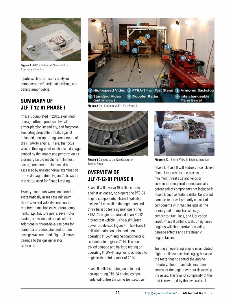
JLF-T-12-01 TEST LOCATIONThe US Army Research Laboratory, Survivability/Lethality Analysis Directorate (ARL/SLAD) is conducting Phase I and II testing at ARL’s Rotorcraft Survivability Assessment Facility (see Figure 1) located at Experimental Facility 6/7 (EF6/7), Aberdeen Proving Ground, MD. EF6/7 is an integrated group of indoor and outdoor firing locations and support facilities, which provides essential ballistic and high explosives test/experimentation capabilities and services to the Army, DoD, and DoD contractors. The ranges enable ballistic experiments with targets from compo-nents through full-scale operating aircraft (and other combat vehicles) against direct fire munitions up to caliber 120 mm and warhead/explosive charge weights up to 50 lbs. EF6/7 utilizes state-of-the-art data acquisition, recording, and process-ing equipment to support vulnerability methodology development, vulnerability reduction studies, warhead lethality studies, and Vulnerability/Lethality model
23 http://jaspo.csd.disa.mil AS Journal 14 / SPRING
inputs, such as criticality analyses, component dysfunction algorithms, and behind armor debris.
SUMMARY OF JLF-T-12-01 PHASE IPhase I, completed in 2012, examined damage effects produced by ball, armor-piercing incendiary, and fragment-simulating projectile threats against unloaded, non-operating components of the PT6A-34 engine. There, the focus was on the degree of mechanical damage caused by the impact and penetration as a primary failure mechanism. In most cases, component failure could be assessed by unaided visual examination of the damaged item. Figure 2 shows the test setup used for Phase I testing.
Twenty-nine tests were conducted to systematically assess the minimum threat size and velocity combination required to mechanically defeat compo-nents (e.g., fracture gears, sever rotor blades, or disconnect a main shaft). Additionally, threat-hole-size data for compressor, combustor, and turbine casings was recorded. Figure 3 shows damage to the gas generator turbine rotor.
OVERVIEW OF JLF-T-12-01 PHASE IIPhase II will involve 15 ballistic tests against unloaded, non-operating PT6-34 engine components. Phase II will also include 31 controlled damage tests and three ballistic tests against operating PT6A-41 engines, installed in an RC-12 ground test vehicle, using a simulated power profile (see Figure 4). The Phase II ballistic testing on unloaded, non- operating PT6-34 engine components is scheduled to begin in 2014. The con-trolled damage and ballistic testing on operating PT6A-41 engines is schedule to begin in the third quarter of 2014.
Phase II ballistic testing on unloaded, non-operating PT6-34 engine compo-nents will utilize the same test setup as
Phase I. Phase II will address inconclusive Phase I test results and assess the minimum threat size and velocity combination required to mechanically defeat select components not included in Phase I, such as turbine disks. Controlled damage tests will primarily consist of components with fluid leakage as the primary failure mechanism (e.g., combustor, fuel lines, and lubrication lines). Phase II ballistic tests on dynamic engines will characterize cascading damage effects and catastrophic engine failure.
Testing an operating engine in simulated flight profile can be challenging because the tester has to control the engine remotely, shoot it, and still maintain control of the engine without destroying the asset. The level of complexity of the test is rewarded by the invaluable data
Figure 1 EF6/7’s Rotorcraft Survivability Assessment Facility
Figure 2 Test Setup for JLFT-12-01 Phase I
Figure 3 Damage to the Gas Generator Turbine Rotor
Figure 4 RC-12 with PT6A-41 Engines Installed

AS Journal 14 / SPRING http://jaspo.csd.disa.mil 24
that the opportunity to test a fully operating engine in flight simulation provides.
HOW THE DATA WILL BE USEDPhase I and II test data will be used to determine dysfunction criteria for critical engine components (e.g., rotors, bearings, shafts, etc.). Engine vulnerability is defined by the dysfunction of individual critical components, not the aircraft vulnerability. For components with more than one failure mode, there may be more than one probability of component dysfunction given a hit, (Pcd|h). As an example, a generic gearbox has two failure modes associated with engine failure, mechanical damage resulting in an immediate loss of torque, and mechanical damage resulting in a loss of lubrication. Each failure mode would have its own Pcd|h, which is analyzed separately in the ballistic vulnerability model.
The Pcd|h is a function of the threat, velocity, vulnerable area, presented area, and dysfunction criteria. For example, combustor failure is a function of air leakage, which in turn, is a function of hole size. Controlled damage testing will determine the hole size critical for engine failure. That hole size is the dysfunction criteria for the combustor. Then, the presented areas and sensitive areas are calculated for each isometric face of the component. A combination of engineering codes and analysis will create a threat/velocity step function of the dysfunction probability averaged over multiple views. This step function is the component Pcd|h. The Pcd|h data for the engine can then be linked to aircraft probability of kill given component dysfunction data for aircraft vulnerability studies. The Phase I
and II test data will also be used to identify vulnerability reduction measures for the engine.
BENEFITS OF JLF-T-12-01Though the program requires scarce and expensive assets, and presents a challenging test setup, the needs the program meets and the benefits that will be realized to the soldier are great. First, the empirical data generated during the program will be used to improve vulnerability estimates used for all aircraft models using the PT6A engine, increasing our understanding of a multitude of different aircrafts. Perhaps most important is the opportunity to increase our understanding of the vulnerability of the many aircraft that do not undergo traditional live fire test and evaluation, but are being targeted in current combat operations.
Due to the PT6A engine’s extensive use across the services and the large impact that JLF-T-12-01 will have on understand-ing the vulnerability of those aircraft is illustrated in the upcoming array of applications for the test data. The new vulnerability curves created using this new data may be used with respect to the EMARSS aircraft. As the US Air Force makes decisions on its light attack aircraft, the vulnerability analysis of those would also benefit from this program. In addition, Homeland Security aircraft will benefit by using the improved vulnerability curves developed during JLF-T-12-01.

25 http://jaspo.csd.disa.mil AS Journal 14 / SPRING
OCCUPANT CASUALTY M&S
by Mark E. Robeson
United Technologies Research Center (UTRC), Sikorsky Aircraft Corporation (SAC), and the US Army’s Aviation Development Directorate (ADD) – Aviation Applied Technology Directorate (AATD), with additional funding from the Joint Aircraft Survivability Program Office (JASPO), developed and demon-strated an affordable, lightweight integrally armored helicopter floor. The floor was designed using the architecture of the Sikorsky H-60 platform, and was required to perform all of the functions of the current floor while also providing ballistic protection from a 7.62 mm ball threat. While various floor designs and ballistic material systems were initially considered, the lightweight integrally armored floor (LIAF) design eventually evolved into a three-layer stack configuration, consisting of a structural strike face, backed by a ballistic material layer, and a sandwich core layer for stiffness and to add depth for recessing floor fittings. Through fabrication trials and ballistic tests, a reduced-weight system that defeated the specified threat, while meeting the load and durability requirements, was developed.
LIGHTWEIGHT INTEGRALLY ARMORED HELICOPTER FLOOR
REQUIREMENTS & BASELINES The LIAF was required to provide ballistic protection from the 7.62 mm ball (i.e., not armor-piercing) threat, while still performing all of the functions of the current floor. The LIAF also had weight goals of at least 33% less than a baseline floor/armor system using parasitic (add-on) steel armor, and less than the currently fielded optimized polyethylene-based floor armor. In addition, the LIAF had to meet load bearing and durability requirements, including a challenging 200 lb wood box-drop test.
Baseline systems of the current UH-60 floor with parasitic steel armor (Figure 1) and the current floor with fielded parasitic polyethylene armor (Figure 2) were defined, with weights corresponding to an area of typical cabin coverage.
CONFIGURATION TRADES AND DOWN SELECT UTRC, Sikorsky, and ADD–AATD developed design concepts for the LIAF. The ballistic protection would be provided by the use of a structural strike face combined with a layer of non-structural
ballistic material, such as Dyneema™, reducing the thickness of the ballistic material required while providing some structural material. An added top skin would provide a walking surface, fluid barrier, and barrier against damage. The purpose of the strike face is to strip the jacket, slow the round, and provide
Figure 1 Baseline Floor / Steel Armor System
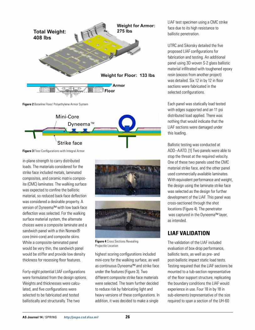
AS Journal 14 / SPRING http://jaspo.csd.disa.mil 26
in-plane strength to carry distributed loads. The materials considered for the strike face included metals, laminated composites, and ceramic matrix compos-ite (CMC) laminates. The walking surface was expected to confine the ballistic material, so reduced back-face deflection was considered a desirable property. A version of Dyneema™ with low back-face deflection was selected. For the walking surface material system, the alternate choices were a composite laminate and a sandwich panel with a thin Nomex® core (mini-core) and composite skins. While a composite-laminated panel would be very thin, the sandwich panel would be stiffer and provide low density thickness for recessing floor features.
Forty-eight potential LIAF configurations were formulated from the design options. Weights and thicknesses were calcu-lated, and five configurations were selected to be fabricated and tested ballistically and structurally. The two
highest scoring configurations included mini-core for the walking surface, as well as continuous Dyneema™ and strike face under the features (Figure 3). Two different composite strike face materials were selected. The team further decided to reduce risk by fabricating light and heavy versions of these configurations. In addition, it was decided to make a single
LIAF test specimen using a CMC strike face due to its high resistance to ballistic penetration.
UTRC and Sikorsky detailed the five proposed LIAF configurations for fabrication and testing. An additional panel using 3D woven S-2 glass ballistic material infiltrated with toughened epoxy resin (excess from another project) was detailed. Six 12 in by 12 in floor sections were fabricated in the selected configurations.
Each panel was statically load tested with edges supported and an 11 psi distributed load applied. There was nothing that would indicate that the LIAF sections were damaged under this loading.
Ballistic testing was conducted at ADD–AATD. [1] Two panels were able to stop the threat at the required velocity. One of these two panels used the CMC material strike face, and the other panel used commercially available laminates. With equivalent performance and weight, the design using the laminate strike face was selected as the design for further development of the LIAF. This panel was cross-sectioned through the shot locations (Figure 4). The penetrator was captured in the Dyneema™ layer, as intended.
LIAF VALIDATION The validation of the LIAF included evaluation of box-drop performance, ballistic tests, as well as pre- and post-ballistic impact static load tests. Testing required that the LIAF sections be mounted to a tub-section representative of the floor support structure, replicating the boundary conditions the LIAF would experience in use. Four 18 in by 18 in sub-elements (representative of the size required to span a section of the UH-60
Mini-Core
Strike face
Dyneema™
Figure 3 Floor Configurations with Integral Armor
Figure 4 Cross Sections Revealing Projectile Location
Figure 2 Baseline Floor/ Polyethylene Armor System

27 http://jaspo.csd.disa.mil AS Journal 14 / SPRING
floor support structure) were manufac-tured, one for the box-drop test, and three for ballistic testing.
The box-drop test was performed on one of the sub-elements. A 200 lb box was raised 15 in above the floor and dropped onto the center of the floor panel so that one corner of the box impacted the floor (Figure 5). The requirement for passing the box-drop test is that the permanent local deformation in the floor caused by this impact not exceed a depth of 0.3 in. The LIAF panel sustained very little damage due to the box-drop impact; the dent was measured to be 0.021 in deep. Finite element modeling had predicted a 0.149 in deep dent, so the model was conservative. The LIAF passed the test.
Two of the three LIAF sub-elements were tested with a distributed static load of just over 11 psi. There was nothing that would indicate that the LIAF sections were damaged under this loading.
Ballistic testing of three floor sub-ele-ments was conducted by ADD–AATD. [2] One floor sub-element was mounted vertically in a test fixture (Figure 6) and shot once with the specified round at the required velocity. A second sub-element was shot three times. The last sub-element was shot five times. In total, the sub-elements were shot nine times. The additional impacts were performed to generate more test data. It was clear that the impact damage was localized and that there was enough undamaged space to allow for the additional tests. All of the rounds (except one impacting an area of reduced thickness) were partial penetra-tions, with the projectile stopped by the panel as intended.
The floor sub-element subjected to a single shot was exposed to a distributed static load of just over 11 psi. As before, there was nothing that would indicate that the LIAF sections were damaged under this loading. The maximum deflection of the pre-shot top surface of the floor was 0.26 in, which increased to 0.32 in after impact.
LIAF OPTIMIZATION Due to the better-than-expected results in the LIAF sub-element ballistic tests, an optimized (lighter) LIAF configuration was considered. Based on engineering estimates, it was proposed to decrease the weight by reducing the thickness of the strike face by 40%. The panel that had previously been box-drop tested was modified to the optimized LIAF configuration. The strike face was removed and replaced with one 40% lighter. The core and the Dyneema™ layers remained unchanged.
The lighter LIAF configuration was quasi-statically load tested. The LIAF was mounted to the tub section during the test and slightly over 11 psi was applied
to the top surface. The maximum pre-shot deflection increased slightly to 0.30 in from 0.26 in. There is no stiffness requirement for the LIAF. There was nothing that would indicate that the LIAF sections were damaged under this loading.
The optimized LIAF sub-element was ballistically tested by ADD–AATD. [3] ADD–AATD shot the panel a total of seven times with 7.62 mm ball rounds at various velocities to calculate a V50. V50 is the velocity at which 50% of the shots go through and 50% are stopped by the armor, and serves to quantify the effectiveness of the armor. Of the seven shots, five were stopped (partial penetrations). Four shots (two partial and two complete penetrations) were used to determine the V50. The calculated four-shot V50 is above the required velocity for the optimized LIAF design. Two of the impacts were cross-sectioned (Figure 7). The round remained vertical in one, but turned completely horizontal in the other. In both cases, there is a residual un-penetrated thickness of the Dyneema™. As with the previous (heavier) LIAF design, there was no indication of loss of integrity or strength.
The earlier box-drop test was performed on the heavier LIAF panel, and was not repeated for the optimized (lighter) design. The conservative finite element
Figure 5 Box-Drop Test Setup
Figure 6 Sub-Element in Ballistic Test Fixture
Figure 7 Cross Section Views through Impact Locations

AS Journal 14 / SPRING http://jaspo.csd.disa.mil 28
model predicted that the lighter design would pass the box-drop test and the maximum stress in the strike face would increase from 38,000 psi to 44,000 psi, still well below the 100,000 psi strength of this material. The dent in the top surface was now predicted to be 0.121 in using the conservative model.
The optimized LIAF design was considered validated at this point.
WEIGHT ANALYSIS The optimized LIAF is predicted to weigh 338 lbs (for an area of typical cabin coverage), including features and attachment hardware. A weight compari-son for the various floors and armor systems (representing the baseline systems) in an H-60 installation corre-sponding to an area of typical cabin coverage (Table 1) shows that the optimized LIAF is 40.5% and 17.2% lighter than the steel-based and opti-mized polyethylene-based fielded floor-armor combinations, respectively.
CONCLUSIONS The LIAF met all of the weight, ballistic performance, and durability requirements identified at the beginning of this project. The LIAF is 40.5% lighter than combina-tion of the current floor with parasitic steel armor, and 17.2% lighter than
combination of the current floor with the fielded, optimized polyethylene-based armor system. The LIAF demonstrated a V50 above the requirement, verifying its ballistic adequacy. Load carrying capability and box-drop test performance were satisfied through a combination of test and analysis. Furthermore, the ballistic tests demonstrated that the LIAF has multi-strike capability.
ACKNOWLEDGEMENTS This project was partially funded by the AATD under Agreement No. W911W6-06-2-0001 and by JASPO as Project No. V-06-01. The US government is autho-rized to reproduce and distribute reprints for government purposes notwithstand-ing any copyright notation thereon. The views and conclusions contained in this document are those of the authors and should not be interpreted as representing the official policies, either expressed or implied, of the AATD, JASPO, or the US government.
The author wishes to thank Connie Bird (United Technologies Aerospace Systems, formerly with UTRC), Alan Goodworth (Sikorsky), Ken Branham (JASPO), and Dennis Lindell (JASPO), without whom this project would not have been possible.
REFERENCES
[1] Robeson, M., “Lightweight Integrally Armored Floor (LIAF) Ballistic Testing,” ADD–AATD Technical Report TR 11-D-33, DTIC AD Number ADA542655, March 2011.
[2] Robeson, M., “Lightweight Integrally Armored Floor (LIAF) Ballistic Validation Testing,” ADD–AATD Technical Report TR 12-D-19, DTIC AD Number ADB378930, January 2012.
[3] Robeson, M., “Lightweight Integrally Armored Floor (LIAF) Ballistic Optimization Testing,” ADD–AATD Technical Report TR 12-D-55, May 2012.
Floor Armor System Weight
Weight Comparisom
Nomex® Core Floor 133 lb
Steel 435 lb
568 lb Baseline A
Nomex® Core Floor 133 lb
Poly 275 lb
408 lbBaseline B 28.2% less
than A
Lightweight Integrally Armored
Floor 338 lb
338 lb
40.5 % less than A
17.2 % less than B
Table 1 Installed Floor Weight Comparison

29 http://jaspo.csd.disa.mil AS Journal 14 / SPRING
OCCUPANT CASUALTY M&S
by Yeondeog Koo and Jongmin Lee
This paper introduces an optimal conceptual design of a MWS that improves survivability of low speed aircrafts. The design is implemented by fusing data of both an ultraviolet (UV) sensor and a radar sensor. The proposed MWS system is able to detect threats of infrared (IR)-based man portable air defense system (MANPADS) as well as radar/laser-guided missiles and unguided rockets more effectively.
AN OPTIMAL CONCEPTUAL DESIGN OF A MISSILE WARNING SYSTEM (MWS)
INTRODUCTION The main threats to low-speed aircrafts are ground-launched weapons, such as missiles (IR, radar, or laser guided), rockets, and anti-aircraft artillery systems. IR-guided missiles, or MANPADS, track the IR signature of aircrafts. These types of missiles are detected by MWS, while flares or directional infrared countermeasures (DIRCMs) are used to decoy this threat. Radar-guided missiles use a detection radar and a tracking radar. This kind of missile threat can be detected by the radar warning receiver (RWR) and distracted by chaffs. Laser-guided missiles operate using either the laser target designator or the laser beam rider. These types of missiles can be detected by the laser warning receiver (LWR) and can be avoided by performing a sudden evasion maneuver. Most anti-aircraft artillery systems use the laser range finder (LRF) and radars. LWR and RWR are able to detect the signals of LRF and radars, and either evasion maneuver or chaff is implemented to avoid the threat of anti-aircraft artillery systems. Rockets that are not guided and have a relatively short effective fire range can be a critical
threat to aircrafts performing takeoff/landing or flying over a short distance from them. Rockets are usually detect-able by MWS, and can be avoided by the performance of an evasion maneuver.
Among the reviewed threats, MANPADS is the most critical and widespread threat for low-speed aircrafts, such as helicop-ters, freighters, and civil planes. Its high mobility, easiness of operation, and cost effectiveness boost the spread speed of MANPADS over the world. In fact, more than 1,000,000 units have been produced since 1970. [1] Although MANPADS is detected by MWS, the current detection reliability of MWS is not as high as RWR and LWR because of a relatively high false alarm rate. This study presents the design of an effective MWS system to detect not only most missile types, but also MANPADS.
MWS STATUS, CURRENT ISSUES, AND POSSIBLE IMPROVEMENTThere are two types of MWS: passive and active. Passive detection technology tracks an IR or UV emitted by the after-burn flames of the missile. Active
detection is performed by detecting and analyzing Doppler signals of the radar signal reflected from the missile.
The critical performances of MWS are high detection probability, low false alarm rate, short detection and warning time, information of attack angle and missile arrival time, covertness, low cost and power consumption, and light weight. Table 1 lists a comparison of features among three major types of MWS.
Based on the author’s research and development and test & evaluation experiences, most MWS have the following common issues during mission operation:
1. They have a relatively high false alarm rate.
2. It is impossible to know the estimated arrival time of missiles when the passive sensor is in operation.
Once a threat alarm is activated, both aircraft pilot and crew experience extreme levels of stress. In addition, false alarms may result in a waste of chaffs and flares, and ultimately lead to a shortage of countermeasures against real
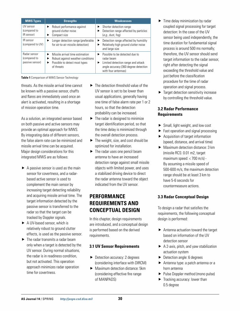
AS Journal 14 / SPRING http://jaspo.csd.disa.mil 30
threats. As the missile arrival time cannot be known with a passive sensor, chaffs and flares are immediately used once an alert is activated, resulting in a shortage of mission operation time.
As a solution, an integrated sensor based on both passive and active sensors may provide an optimal approach for MWS. By integrating data of different sensors, the false alarm rate can be minimized and missile arrival time can be acquired. Major design considerations for this integrated MWS are as follows:
� A passive sensor is used as the main sensor for covertness, and a radar-based active sensor is used to complement the main sensor by increasing target detecting reliability and acquiring missile arrival time. The target information detected by the passive sensor is transferred to the radar so that the target can be tracked by Doppler signals.
� A UV-based sensor, which is relatively robust to ground clutter effects, is used as the passive sensor.
� The radar transmits a radar beam only when a target is detected by the UV sensor. During normal situations, the radar is in readiness condition, but not activated. This operation approach minimizes radar operation time for covertness.
� The detection threshold value of the UV sensor is set to be lower than usual applications, generally having one time of false alarm rate per 1 or 2 hours, so that the detection probability can be increased.
� The radar is designed to minimize target identification period, so that the time delay is minimized through the overall detection process.
� The weight, size, and cost should be optimized for installation.
� The radar uses one pencil beam antenna to have an increased detection range against small missile objects with limited power, and uses a stabilized driving device to direct the radar antenna toward the object indicated from the UV sensor.
PERFORMANCE REQUIREMENTS AND CONCEPTUAL DESIGNIn this chapter, design requirements are introduced, and a conceptual design is performed based on the derived requirements.
3.1 UV Sensor Requirements
� Detection accuracy: 2 degrees (considering interface with DIRCM)
� Maximum detection distance: 5km (considering effective fire range of MANPADS)
� Time delay minimization by radar coupled signal processing for target detection: In the case of the UV sensor being used independently, the time duration for fundamental signal process is around 500 ms normally; therefore, the UV sensor should send target information to the radar sensor, right after detecting the signal exceeding the threshold value and just before the classification procedure for the time of radar operation and signal process.
� Target detection sensitivity increase by controlling the threshold value.
3.2 Radar Performance Requirements
� Small, light weight, and low cost � Fast operation and signal processing � Acquisition of target information
(speed, distance, and arrival time) � Maximum detection distance: 3 km
(missile RCS: 0.01 m2, target maximum speed: < 700 m/s) - By assuming a missile speed of 500-600 m/s, the maximum detection range should be at least 3 km to have 5-6 seconds for countermeasure actions.
3.3 Radar Conceptual Design
To design a radar that satisfies the requirements, the following conceptual design is performed:
� Antenna actuation toward the target based on information of the UV detection sensor
� A 2-axis, pitch, and yaw stabilization actuation system
� Detection angle: 6 degrees � Antenna type: a patch antenna or a
horn antenna � Pulse Doppler method (mono pulse) � Tracking accuracy: lower than
0.5 degree
MWS Types Strengths Weaknesses
UV sensor (compared to IR sensor)
� Robust performance against ground clutter noise
� Compact size
� Shorter detection range � Detection range affected by particles
(e.g., dust, fog)
IR sensor (compared to UV)
� Longer detection range (preferable for air-to-air missile detection)
� Detection range affected by humidity � Relatively high ground clutter noise
and large size
Radar sensor (compared to passive sensor)
� Missile arrival time estimation � Robust against weather conditions � Possible to detect most types
of threats
� Possible to be detected due to radar beam
� Limited detection range and attack angle accuracy (360 degree detection with four antennas)
Table 1 Comparison of MWS Sensor Technology
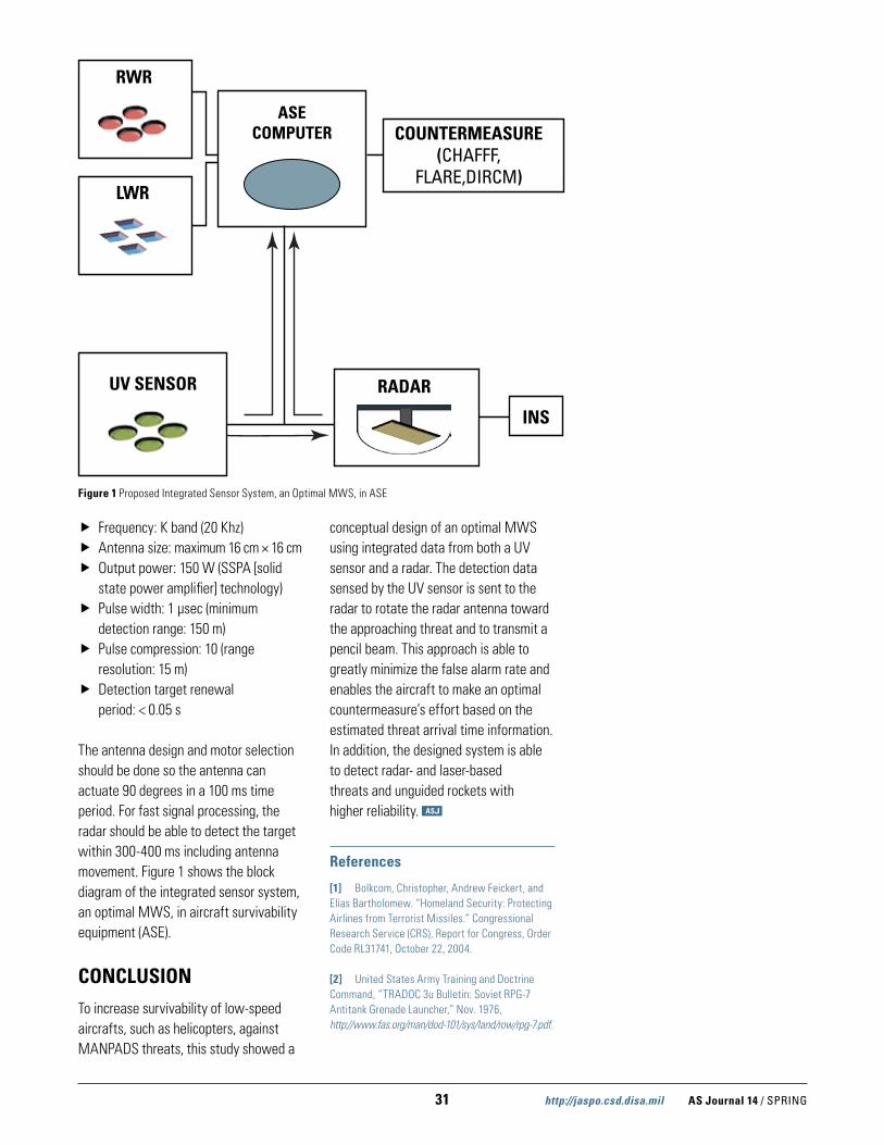
31 http://jaspo.csd.disa.mil AS Journal 14 / SPRING
� Frequency: K band (20 Khz) � Antenna size: maximum 16 cm × 16 cm � Output power: 150 W (SSPA [solid
state power amplifier] technology) � Pulse width: 1 μsec (minimum
detection range: 150 m) � Pulse compression: 10 (range
resolution: 15 m) � Detection target renewal
period: < 0.05 s
The antenna design and motor selection should be done so the antenna can actuate 90 degrees in a 100 ms time period. For fast signal processing, the radar should be able to detect the target within 300-400 ms including antenna movement. Figure 1 shows the block diagram of the integrated sensor system, an optimal MWS, in aircraft survivability equipment (ASE).
CONCLUSIONTo increase survivability of low-speed aircrafts, such as helicopters, against MANPADS threats, this study showed a
conceptual design of an optimal MWS using integrated data from both a UV sensor and a radar. The detection data sensed by the UV sensor is sent to the radar to rotate the radar antenna toward the approaching threat and to transmit a pencil beam. This approach is able to greatly minimize the false alarm rate and enables the aircraft to make an optimal countermeasure’s effort based on the estimated threat arrival time information. In addition, the designed system is able to detect radar- and laser-based threats and unguided rockets with higher reliability.
References
[1] Bolkcom, Christopher, Andrew Feickert, and Elias Bartholomew. “Homeland Security: Protecting Airlines from Terrorist Missiles.” Congressional Research Service (CRS), Report for Congress, Order Code RL31741, October 22, 2004.
[2] United States Army Training and Doctrine Command, “TRADOC 3u Bulletin: Soviet RPG-7 Antitank Grenade Launcher,” Nov. 1976, http://www.fas.org/man/dod-101/sys/land/row/rpg-7.pdf.
RWR
ASE COMPUTER COUNTERMEASURE
(CHAFFF, FLARE,DIRCM)
LWR
INS
UV SENSOR RADAR
Figure 1 Proposed Integrated Sensor System, an Optimal MWS, in ASE

AS Journal 14 / SPRING http://jaspo.csd.disa.mil 32
WHY RASE?Irregular warfare that is associated with overseas contingency operations has underscored a need for investment in aircraft survivability equipment (ASE), particularly hostile fire indication (HFI) systems. The Office of the Undersecretary of Defense (Acquisition, Technology, and Logistics) report to Congress, Study on Rotorcraft Safety and Survivability (September 2009), investi-gated conditions that led to loss of life and rotary wing aircraft from October 2001 through September 2009, and provided safety and survivability recommendations. One specific recom-mendation was to improve rotorcraft situational awareness and threat detection capability with better ASE systems. RASE was established in 2011 to satisfy this requirement. The effort continued through 2013.
The goals for RASE were to fill data collection gaps on fielded and soon-to-be-fielded ASE systems and to help accelerate the development of ASE-related capabilities based on current
warfighter requirements. The vision for RASE was to enhance decision makers’ understanding of ASE performance and improve the state of the art of ASE testing. RASE, held annually since 2011, took positive steps in implementing study recommendations associated with HFI systems while serving as a catalyst for innovation within the ASE community. RASE improved realism and standardiza-tion in the testing of ASE, improved the extent of testing prior to fielding, and leveraged modest Department of Defense investment to save overall experimentation costs.
RASE BACKGROUNDRASE was sponsored by the Assistant Secretary of Defense for Research and Engineering (ASD[R&E]) Director, Electronic Warfare and Countermeasures Office and led by the Joint Electronic Advanced Technology (JEAT) Project Office, NAWCWD, Point Mugu, CA. Leveraging a modest investment, the RASE venue provided range resources, platforms, weapons, ammunition, and data management, as well as a detailed
experiment plan and the general structure to conduct effective experimen-tation in technical and combat-relevant conditions. The RASE venue provided the only way some developers could assess their system’s performance against actual threat weapons.
RASE program offices and HFI developers from private industry gathered a large amount of system and sensor perfor-mance data at a fraction of the cost of individual test and evaluation efforts. Due to equipment commonality, RASE
OCCUPANT CASUALTY M&S
by Dennis Duquette and Kevin Gross
“Five, Four, Three, Two, One, Fire!” In September 2013, the Fire Control Officer issued this command 811 times before shooting more than 10,900 rounds of ammunition during the Rotorcraft Aircraft Survivability Equipment (RASE) Experiment, a 12-day live fire venue. The RASE 2013 experiment was conducted at a remote test site at Weapons Survivability Laboratory (WSL), Naval Air Warfare Center Weapons Division (NAWCWD), China Lake, CA. Figure 1 shows the platform, a decommissioned, unmanned SH-60B mounted on a 30-foot pedestal. Joint services, international partners, and industry developers installed 23 systems with over 100 individual sensors on or near the Hover Helicopter.
RASE EXPERIMENTS IMPROVE AIRCRAFT SURVIVABILITY
Figure 1 Hover Helicopter (RASE 2012 & 2013)

33 http://jaspo.csd.disa.mil AS Journal 14 / SPRING
data were available to address some ASE issues applicable to both fixed-wing and rotary-wing aircraft. Other participants, such as threat signature model develop-ers and instrumentation developers who needed threat signature and prototype ground truth data, participated in the experiments on a non-interference basis.
EXPERIMENT MANAGEMENT As a joint services experiment led by a small project office, the experiment management team (EMT) was critical to the planning and execution of the event. The JEAT project manager collaborated with service programs of record, who enthusiastically provided resources such as personnel, material, and funding. The EMT determined the venue for each year as well as experiment objectives, gun types, and ammunition required (foreign and North Atlantic Treaty Organization [NATO]). The EMT leadership included HFI experts from the following organizations:
� Arnold Engineering and Development Center (AEDC)
� Center for Countermeasures (CCM) � Intelligence and Information Warfare
Directorate � Missile and Space Intelligence Center � Naval Research Laboratory (NRL) � Naval Surface Warfare Center,
Corona Division � PMA-272 Advanced Tactical Aircraft
Protection Systems � Program Management Office
– Aircraft Survivability Equipment � Redstone Test Center (RTC) � Special Operations Research,
Development and Acquisition Center (SORDAC)
� Survivability and Vulnerability Information Analysis Center (SURVIAC)
� Technology Applications Program Office (TAPO)
� Weapons Survivability Laboratory � Yuma Proving Ground (YPG)
Figure 2 provides an overview of the RASE organization.
PARTICIPANTSParticipants were predominately from organizations responsible for passive sensor systems who wanted to collect data to address threat detection, geo-location, and situational awareness requirements. The systems detected threats in ultraviolet, near infrared, shortwave infrared, mid-wave infrared, and radio frequency portions of the electro-magnetic spectrum, or detected projectiles by their acoustic signatures. The US government provided the venue, weapons, ammunition, range time, and host platforms (SORDAC Maverick Unmanned R-22 helicopters and YPG fixed tower; see Figure 3). Participants reciprocated by providing government sponsorship, self-funding for development and travel costs, and system perfor-mance self-assessment for inclusion in the final report to OSD with the promise that comparative assessments among systems would not be made. RASE was an experimental venue that welcomed failure or setback within the spirit of discovery while encouraging the collaborative innovation of new
technology. Participants understood this construct and reported truthfully without fear of negative repercussion. During RASE 2013, foreign participation included personnel and systems from Australia, Canada, and the United Kingdom in accordance with The Technical Cooperation Program.
WEAPONS AND AMMUNITIONThe successful firing of nearly 11,000 rounds of ammunition in 2013 was made possible through a collaborative, multidisciplinary effort. Weapons and ammunition were hot topics for the team as the scope, objectives, and detailed shot matrix were developed. Plans were developed to shoot foreign manufactured ammunition and weapons, including small arms, anti-aircraft artillery, rocket propelled grenades, rockets, and missiles. NATO small arms and ammunition were also included to evaluate differences between NATO and foreign ammunition signatures. The joint ASE community showed support by sharing truth data instrumentation, large caliber weapons, and ammunition. Table 1 summarizes RASE metrics for 2011 through 2013. [1]
EXPERIMENT OBJECTIVESRASE objectives flowed from program requirements with traceability to developer goals as documented in the
EMT
ExperimentDirector (CCM)
Instrumentation Team Lead
(AEDC)
Tower Integration Team Lead (PMA-272)
Data Management and AnalysisTeam Lead
(JEAT)
InternationalCoordinationTeam Lead
(NRL)
Weapons & Ammo (TAPO, PMA-272, JEAT)
Test Conductor(WSL) China Lake
Figure 2 RASE 2013 Organization

AS Journal 14 / SPRING http://jaspo.csd.disa.mil 34
data management and analysis plan (DMAP). In 2013, the participants’ objectives were collected and incorporated into the experiment design. The data collection objectives were as follows:
� Inspire Innovation � Advance Key Technologies � Fill Data Gaps � Employ Operationally Relevant
Weapon Types � Advance ASE Experimentation
RASE 2013 SCENARIOSTo meet the objectives, the EMT developed multi-gun and multi-axis scenarios relevant to ongoing combat conditions. Specifically, the EMT developed a three-gun, three-axis ambush scenario with staggering and simultaneous fire to replicate an actual ambush. The Embankment scenario replicated the impact of rounds
under/close to the Hover helicopter to determine how the ASE sensors classified the sudden stoppage of projectiles. In the Own Ship Return Fire and Wingman Return Fire scenarios, NATO machine guns returned fire close to the hostile fire point of origin. The High Angle of Approach/Over Rotor scenario detected and classified hostile fire above the rotor disk.
TRUTH DATA AND INSTRUMENTATIONTruth data for RASE 2013 were provided by instrumentation from the AEDC, CCM, China Lake Range, and TAPO. Instrumentation included time-synchro-nized signature data from radiometers and imagers, a flash detector at the gun, as well as radar data and meteorological data. The AEDC collected projectile signature data broadside to the gun using high-speed radiometers, high-speed visible imagery, and atmospheric sensors.
The CCM collected similar data from the hilltop behind the Hover helicopter. China Lake Range personnel provided radar truth data to establish time-space- position-information (TSPI) for projectile trajectories to verify projectile miss distances and assist with experiment control. Three Oehler acoustic systems, composed of 16 microphone arrays, served as alternate projectile TSPI sources during scenarios where the use of the Doppler radar was not possible. The systems use shockwave times of arrival to compute firing times and characterize miss distance.
RASE AT YUMA PROVING GROUNDA significant source of ground truth and situational awareness at the Yuma Maverick event in 2012 was a mobile range control and instrumentation system-of-systems developed by Redstone Test Center (RTC), called the RTC Architecture for Test and Evaluation of Hostile Fire Detection System (RATH). Optimized for testing aviation hostile-fire sensors, RATH provided state-of-the-art tracking capabilities, centralized com-mand and control, real-time situational awareness, and efficient data-capture capabilities. RASE 2012 was the first time RATH was deployed outside RTC.
ANALYSISFollowing each RASE experiment, truth data products, such as TSPI, radar ballistic truth data, shot trajectories, and shot signatures, were distributed and analyzed in accordance with the DMAP. Analysis of the objectives, experiment results, conclusions, and recommenda-tions were documented in a final report. There were no Pass/Fail criteria for participating systems, and comparative performance analyses were not conducted.
Figure 3 Maverick Helicopter (RASE 2011 and 2012) and Fixed Tower (RASE 2011)
RASE Metrics 2011 2012 2013
OSD Investment $3.0M $4.5M $1.5M
Venue YPG YPG and WSL WSL
Test AssetsMaverick Helicopter
and Fixed TowerMaverick at YPG Hover
Helicopter at WSLHover Helicopter at WSL
Rounds 2,622 7,092 10,912
RPGs 133 76 18
Rockets 22 24 6
ATGMs 0 19 0
Laser Events 0 0 121
Maverick Sorties / Flight Time(hours)
33 / 36.0 35 / 44.0 0 / 0.0
Hover Helicopter Flight Time (hours)
0.0 7.7 55.4
Table 1 RASE Metrics

35 http://jaspo.csd.disa.mil AS Journal 14 / SPRING
COST BENEFIT ANALYSIS From conception, the RASE venue was designed to improve ASE testing in a cost-effective manner. In 2012, the net cost savings was $37.5M and produced a savings-to-cost ratio of 6.96, or $6.96 saved for every dollar spent. The net cost savings was the difference between the total costs of testing (if conducted separately) and the total actual costs of the venue. For individual developers, a more relevant metric is cost leverage (the dollars-worth of data received for the cost of effort). On average, developers received $39 worth of data for every dollar they spent.
RESULTSRASE encouraged teaming and innova-tion among participating programs and ASE developers. Improvements to ASE included adapting the proven ground acoustic technology to the rotary wing flight environment, reducing the weight of sensor system components, improving threat identification and geo-location capabilities, adapting new technologies to the form-fit constraints of existing
missile warning systems, exploring break-through technologies, and fusing sensor data. RASE produced many “firsts” for the ASE community including those in Table 2.
RECOMMENDATIONSThe primary recommendation is to continue the RASE venue that contains both a baseline set of threat conditions and adds new features that address developer data gaps to accommodate the maturation of HFI technology readiness levels. Additional recommendations include the following:
� Add shots with greater miss dis-tances from different firing points for dynamic flights
� Encourage sharing of RATH technolo-gies with other ASE test ranges
� Promote the development of an automatic firing solution for close-in firing during dynamic flight
� Explore multi-static or monopulse Doppler radars to provide real-time truth data
� Encourage the use of slewed hostile fire that produces more operationally relevant gunfire data for developers
WHAT’S NEXT?Considerable work still needs to be done: improving hostile fire detection, identification, and geo-location; reporting hostile fire across the network; and returning non-kinetic fire at those who wish to do us harm. ASD (R&E) has sponsored RASE for the past 3 years and is seeking service and/or program of record sponsorship to continue this vital and worthy effort. The JEAT Project Office is available to provide advice to the next RASE sponsor(s), but is tasked in other business areas and no longer able to plan, execute, or report on ASE experiments. Who is up for the challenge?
ACKNOWLEDGEMENTSThe JEAT Project Office offers sincere appreciation to the men and women of the many sponsoring and participating organizations that made RASE possible. Special thanks go to Brent Sedler, Michael Reese, Michael Kline, and Benjamin Chitty, whose leadership and expertise forged successful RASE events.
References
[1] “Rotorcraft Aircraft Survivability Equipment Experiment (RASE) 2011 Final Report.” DTIC Accession # SURVIAC-2000425, April 2012 (UNCLASSIFIED).
Wide angle, multi-gun fire presented in hover and dynamic flight (2012)
Horizontal slewing of gunfire (manual 2012, automated 2013) close to a platform in hover and first automated vertical slewing (2012)
Data collection with simultaneous hostile and friendly fire (2012)
Data collection with multiple hostile gun types firing simultaneously (2012)
Data signature collection for various anti-tank guided weapons (2012)
Multi-gun and multi-axis scenarios (2013)
� Three-gun, three-axis ambush � Own ship return fire � Wingman return fire � Embankment fire � High angle of approach/over rotor fire
Three different laser systems (2013)
Simultaneous laser and hostile fire (2013)
23 systems with more than 100 individual sensors installed on the Hover helicopter (2013)
Table 2 RASE Firsts

PRSRT STDU.S. POSTAGE
PAIDPAX RIVER MDPermit No. 22
COMMANDERNAVAL AIR SYSTEMS COMMAND (4.1.8J)47123 BUSE ROADPATUXENT RIVER, MD 20670-1547
Official Business
CALENDAR OF EVENTS
APRAUSA ILW LANPAC Symposium and Exposition 8–10 April 2014Honolulu, HI http://www.ausa.org/meetings/Pages/AUSAILWLANPACSymposiumandExposition.aspx
15th Annual Science & Engineering Technology Conference/Defense Tech Exposition8–10 April 2014Hyattsville, MDhttp://www.ndia.org/meetings/4720/Pages/ default.aspx
Threat Weapons Effects Training22–24 April 2014Hurlburt Field and Eglin Air Force Base, FL
Global Explosive Ordnance Disposal (EOD) Conference and Exhibition 30–1 May 2014Fort Walton Beach, FL http://www.ndia.org/meetings/4950/Pages/ default.aspx
MAY2014 Army Aviation: Mission Solutions Summit 4–6 May 2014Nashville, TN http://www.quad-a.org/index.php/article-layout/27-pagesconventions/426-2014-aamss-registration-date
2014 AAAA Professional Forum and Exposition 4–7 May 2014Nashville, TN http://www.quad-a.org
2014 Tactical Wheeled Vehicles Conference 5–7 May 2014Reston, VA http://www.ndia.org/meetings/3890/Pages/ default.aspx
AUVSI’s Unmanned Systems 2014 12–15 May 2014Orlando, FL http://www.auvsi.org/AUVSI/Events1/UpcomingEvents
17th Annual Test Instrumentation: T&E on a Sustainment Budget 19–23 May 2014Las Vegas, NV http://itea.org/learn/conferences-and-workshops/ 35-share/conferences/240-2013-test-instrumentation-t-e-on-a-sustainment-budget.html
JUN5th Annual Joint Integrated Air and Missile Defense Symposium12 June 2014Laurel, MD http://www.ion.org/meetings/?conf=jnc&CFID=1797
Information for inclusion in theCalendar of Events may be sent to:
SURVIAC, Washington Satellite OfficeAttn: Jerri Limer13200 Woodland Park Road, Suite 6047 Herndon, VA 20171
To change, add or delete your mailing address, please fax a copy of this page with changes to 703/984–0756, send an email to: [email protected]
PRSRT STDU.S. POSTAGE
PAIDPAX RIVER MDPermit No. 22
COMMANDERNAVAL AIR SYSTEMS COMMAND (4.1.8J)47123 BUSE ROADPATUXENT RIVER, MD 20670-1547
Official Business
CALENDAR OF EVENTS