Propulsion Pt2
13
Engine Selection as Part of the Aircraft Design Process Right Propulsion System for Right Job Low bypass turbofan Solid fuel rocket Hybrid rocket motor using nitrous oxide & HPTB rubber 2 GE J85 turbojets Rotax 4-Stroke w/ 2 Blade Prop 2 HBR Turbofans
-
Upload
propellerheadguy -
Category
Documents
-
view
238 -
download
2
Transcript of Propulsion Pt2
8/8/2019 Propulsion Pt2
http://slidepdf.com/reader/full/propulsion-pt2 1/12
Engine Selection as Part of theAircraft Design Process
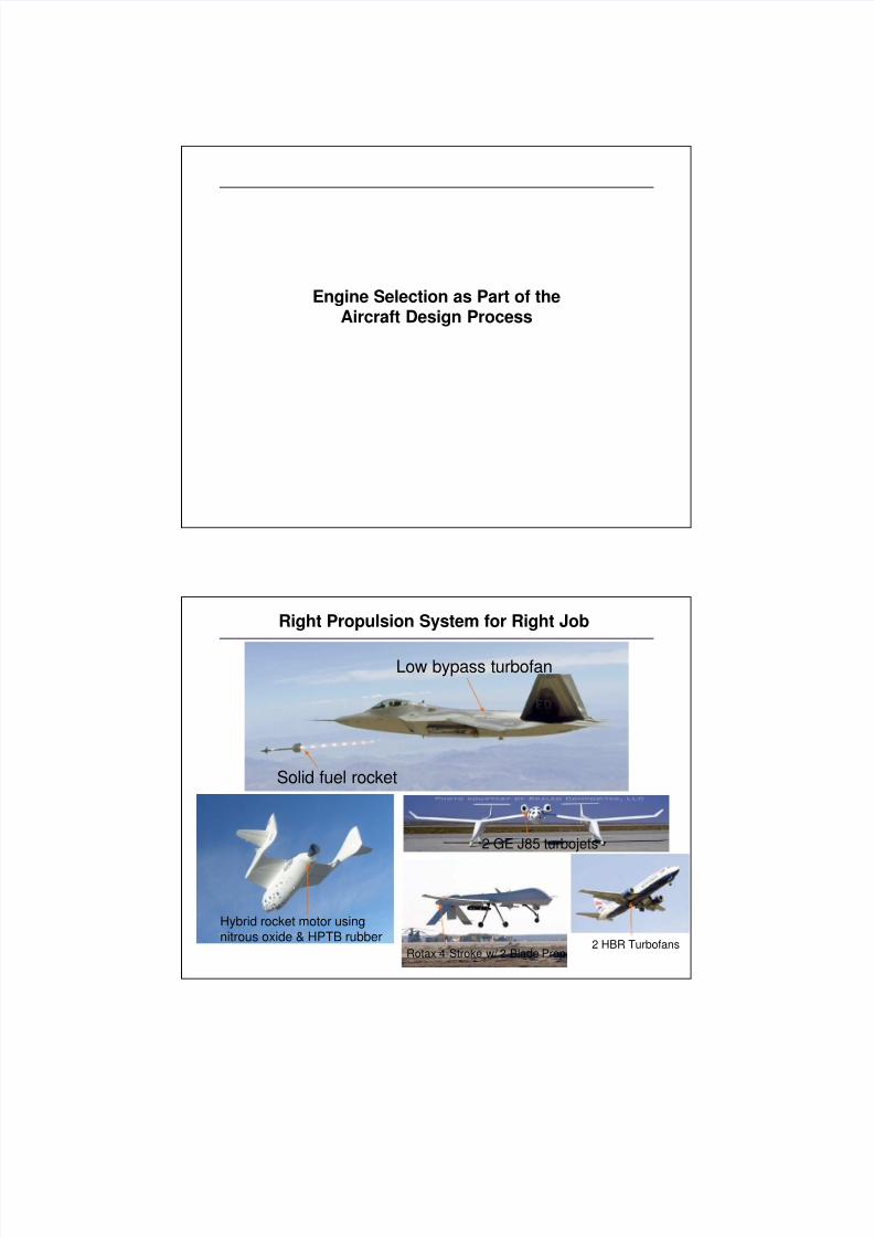
Right Propulsion System for Right Job
Low bypass turbofan
Solid fuel rocket
Hybrid rocket motor using
nitrous oxide & HPTB rubber
2 GE J85 turbojets
Rotax 4-Stroke w/ 2 Blade Prop2 HBR Turbofans
8/8/2019 Propulsion Pt2
http://slidepdf.com/reader/full/propulsion-pt2 2/12
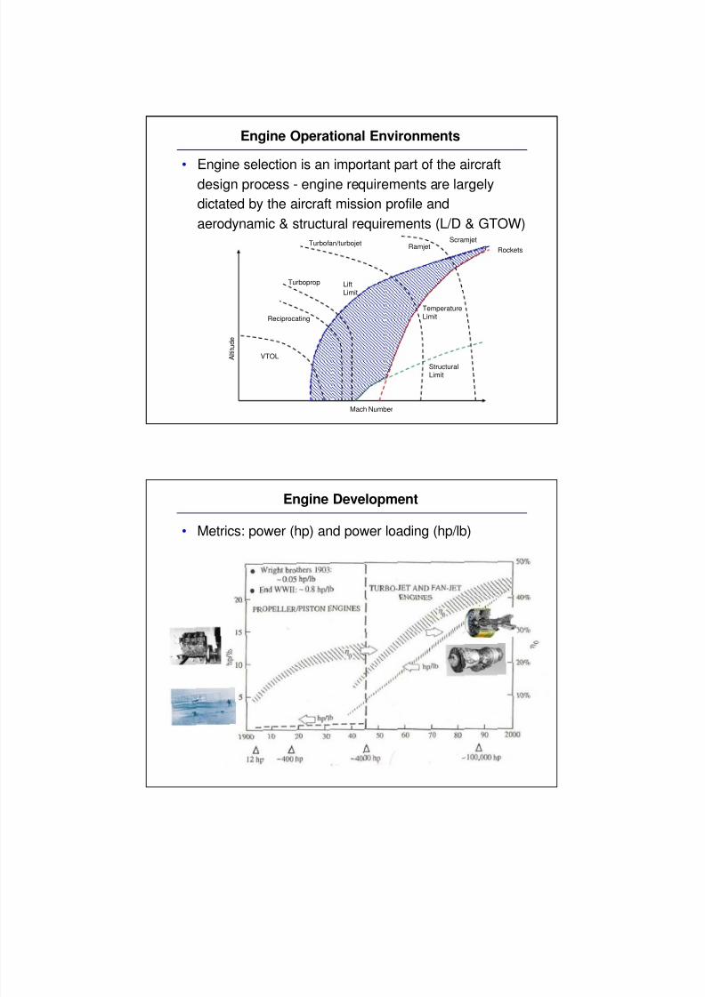
Engine Operational Environments
• Engine selection is an important part of the aircraft
design process - engine requirements are largely
dictated by the aircraft mission profile and
aerodynamic & structural requirements (L/D & GTOW)
StructuralLimit
TemperatureLimit
LiftLimit
Mach Number
A l t i t u d e
RamjetScramjet
Turbofan/turbojet
Turboprop
Reciprocating
Rockets
VTOL
Engine Development
• Metrics: power (hp) and power loading (hp/lb)
8/8/2019 Propulsion Pt2
http://slidepdf.com/reader/full/propulsion-pt2 3/12
Propulsion
• When selecting a propulsion system for a aircraft, ingeneral, determine your desired thrust generation
method
» Propeller
» Jet (turbojet/rocket)
» Other (ornithopter)
• then determine how much power you will need and
which power generation fits best
» Gasoline engine (recip.)
» Gas turbine
» Other chemical (rocket)
» Electric
Propulsion Selection
• Important Criteria
» Thrust required (determined by drag)
» Power required (determined by drag and velocity)
» Weight of engine
» Type of propulsion (propeller, turbine, other)
» Efficiency
» Fuel consumption (SFC or TSFC)
» Range
o Combine with fuel consumption to determine amount of fuel required
» Power loading (hp/W)
• Note that on the thrust and power curves, the maximum velocity
is the same (U max for power and thrust are identical)
• However, the velocity for minimum thrust and minimum power
are different
8/8/2019 Propulsion Pt2
http://slidepdf.com/reader/full/propulsion-pt2 4/12
How Much Fuel?
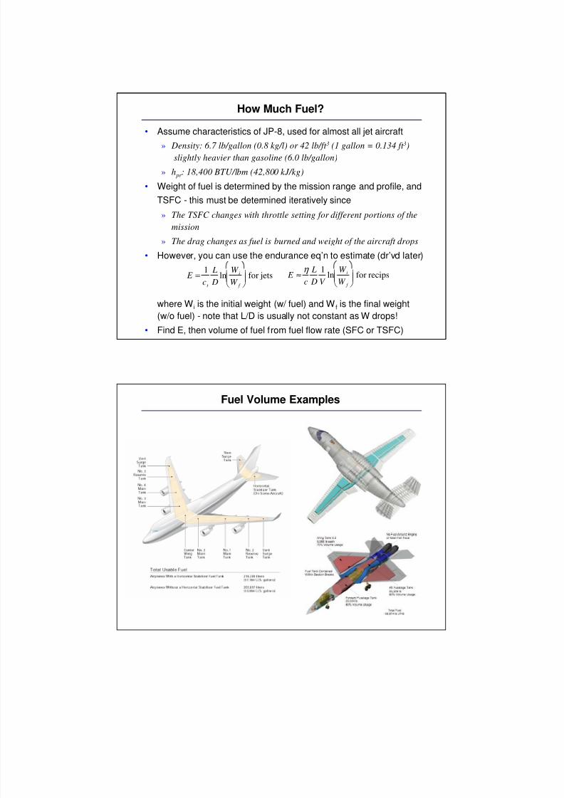
• Assume characteristics of JP-8, used for almost all jet aircraft
» Density: 6.7 lb/gallon (0.8 kg/l) or 42 lb/ft 3 (1 gallon = 0.134 ft 3)
slightly heavier than gasoline (6.0 lb/gallon)
» h pr : 18,400 BTU/lbm (42,800 kJ/kg)
• Weight of fuel is determined by the mission range and profile, and
TSFC - this must be determined iteratively since
» The TSFC changes with throttle setting for different portions of the
mission
» The drag changes as fuel is burned and weight of the aircraft drops
• However, you can use the endurance eq’n to estimate (dr’vd later)
where Wi is the initial weight (w/ fuel) and Wf is the final weight
(w/o fuel) - note that L/D is usually not constant as W drops!
• Find E, then volume of fuel from fuel flow rate (SFC or TSFC)
E =
1
ct
L
D ln
W i
W f
for jets
E ≈η
c
L
D
1
V ln
W i
W f
for recips
Fuel Volume Examples
8/8/2019 Propulsion Pt2
http://slidepdf.com/reader/full/propulsion-pt2 5/12
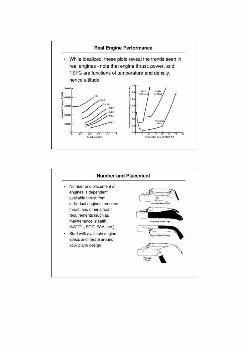
Real Engine Performance
• While idealized, these plots reveal the trends seen inreal engines - note that engine thrust, power, and
TSFC are functions of temperature and density,
hence altitude
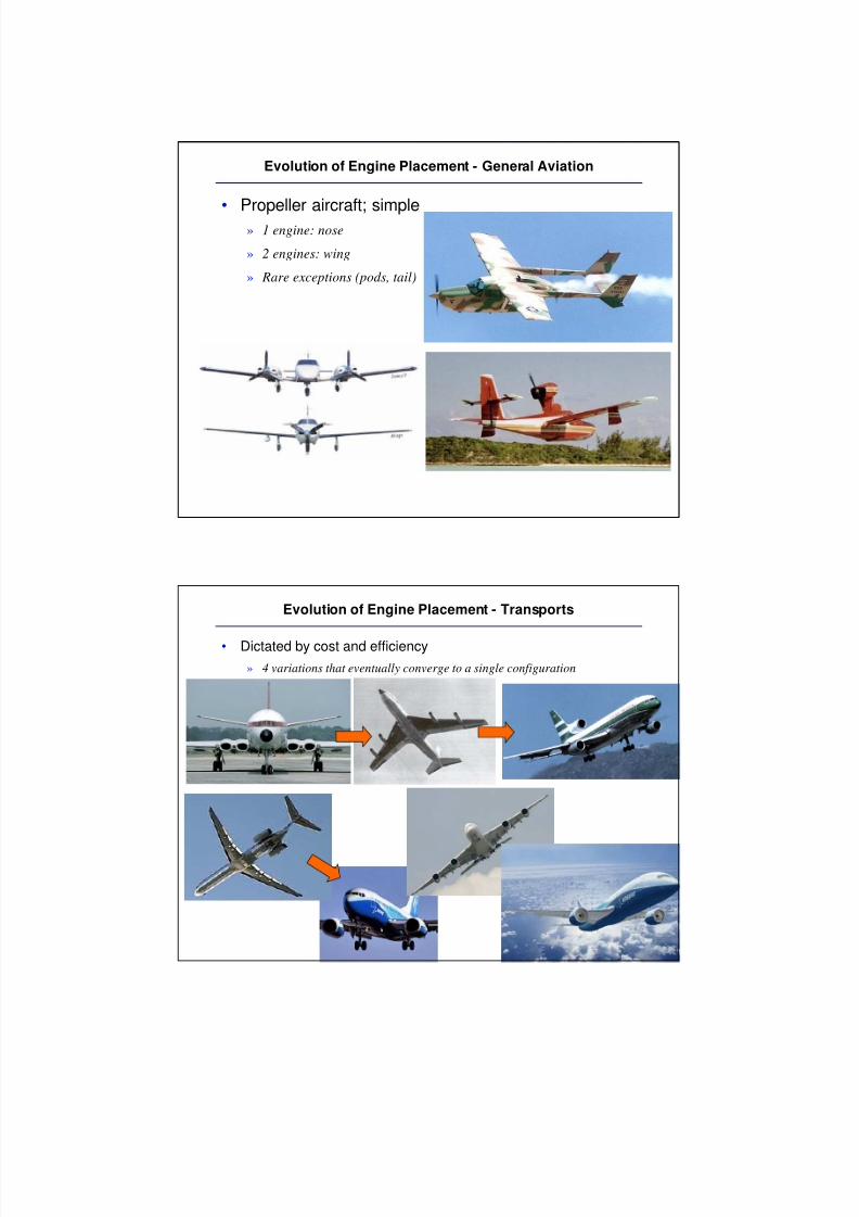
Number and Placement
• Number and placement of
engines is dependent
available thrust from
individual engines, required
thrust, and other aircraft
requirements (such as
maintenance, stealth,
V/STOL, FOD, FAA, etc.)
• Start with available engine
specs and iterate around
your plane design
8/8/2019 Propulsion Pt2
http://slidepdf.com/reader/full/propulsion-pt2 6/12
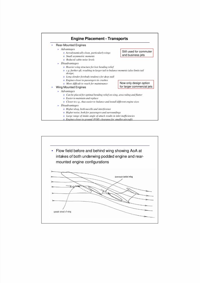
Evolution of Engine Placement - General Aviation
• Propeller aircraft; simple» 1 engine: nose
» 2 engines: wing
» Rare exceptions (pods, tail)
Evolution of Engine Placement - Transports
• Dictated by cost and efficiency
» 4 variations that eventually converge to a single configuration
8/8/2019 Propulsion Pt2
http://slidepdf.com/reader/full/propulsion-pt2 7/12
Engine Placement - Transports
• Rear-Mounted Engines
» Advantageso Aerodynamically clean, particularly wings
o Small asymmetric moments
o Reduced cabin noise levels
» Disadvantages
o Heavier wing structure for lost bending relief
o c.g. further aft, resulting in larger tail to balance moments (also limits taildesign)
o Long slender forebody tendency for deep stall
o Engines closer to passengers in crashes
o More difficult to reach for maintenance
• Wing Mounted Engines
» Advantages
o Can be placed for optimal bending relief on wing, area ruling and flutter
o Easier to maintain and replaceo Closer to c.g., thus easier to balance and install different engine sizes
» Disadvantages
o Higher drag, both nacelle and interference
o Higher noise, both for passengers and surroundings
o Large range of intake angle of attack results in inlet inefficiencies
o Engines closer to ground (FOD, clearance for smaller aircraft)
Still used for commuterand business jets
Now only design option
for larger commercial jets
• Flow field before and behind wing showing AoA at
intakes of both underwing podded engine and rear-
mounted engine configurations
8/8/2019 Propulsion Pt2
http://slidepdf.com/reader/full/propulsion-pt2 8/12
• Flow field characteristics of underwing installation
• Overwing noise shielding
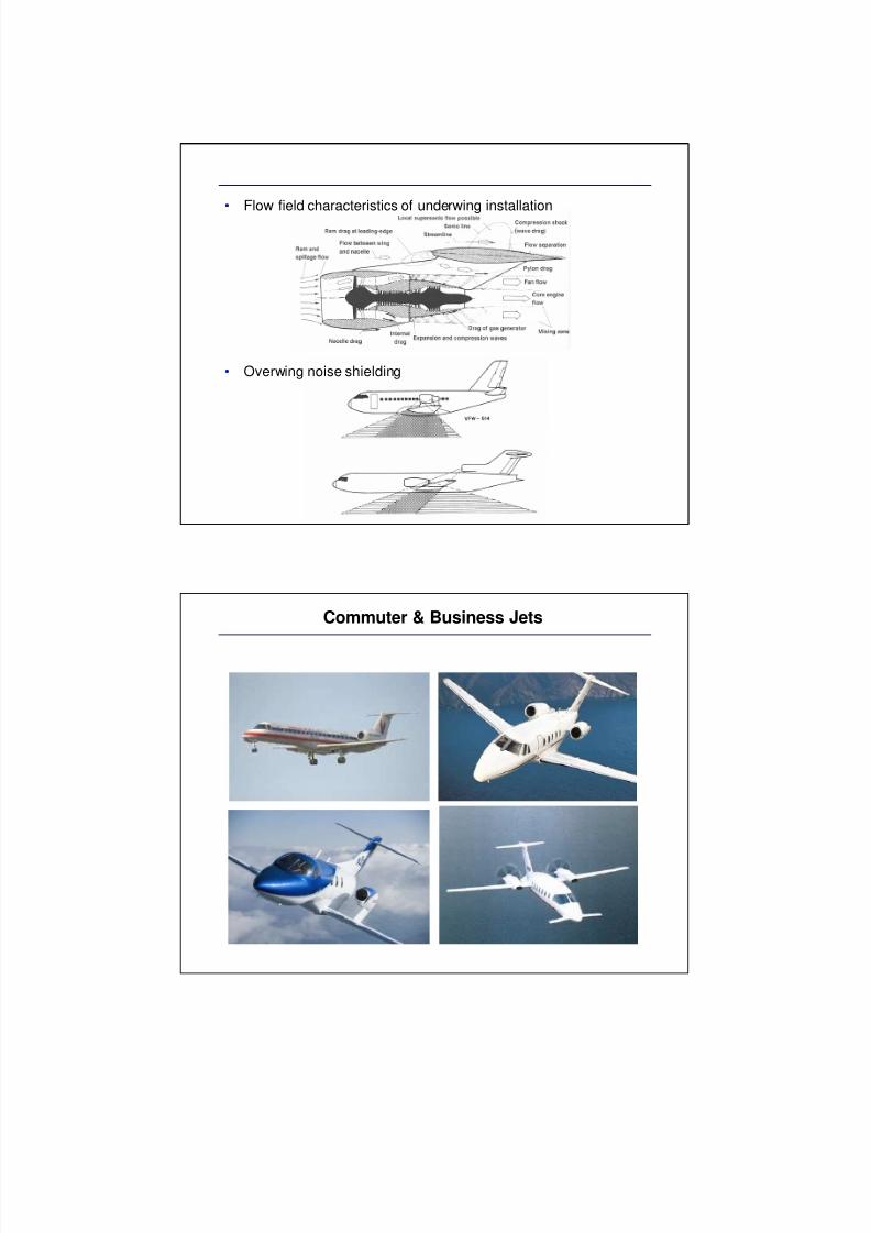
Commuter & Business Jets
8/8/2019 Propulsion Pt2
http://slidepdf.com/reader/full/propulsion-pt2 9/12
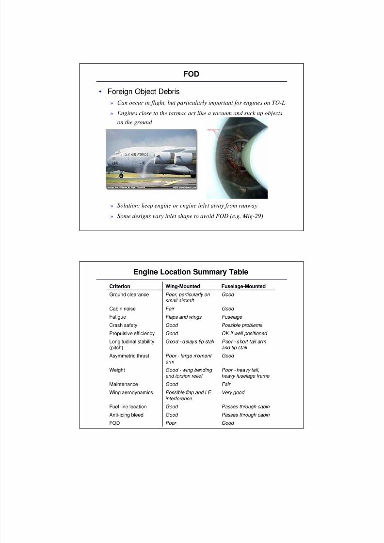
FOD
• Foreign Object Debris» Can occur in flight, but particularly important for engines on TO-L
» Engines close to the tarmac act like a vacuum and suck up objects
on the ground
» Solution: keep engine or engine inlet away from runway
» Some designs vary inlet shape to avoid FOD (e.g. Mig-29)
Engine Location Summary Table
Criterion Wing-Mounted Fuselage-Mounted
Ground clearance Poor, particularly on small aircraft
Good
Cabin noise Fair Good
Fatigue Flaps and wings Fuselage
Crash safety Good Possible problems
Propulsive efficiency Good OK if well positioned
Longitudinal stability(pitch)
Good - delays tip stall Poor - short tail arm and tip stall
Asymmetric thrust Poor - large moment arm
Good
Weight Good - wing bending and torsion relief
Poor - heavy tail,heavy fuselage frame
Maintenance Good Fair
Wing aerodynamics Possible flap and LE interference
Very good
Fuel line location Good Passes through cabin
Anti-icing bleed Good Passes through cabin
FOD Poor Good
8/8/2019 Propulsion Pt2
http://slidepdf.com/reader/full/propulsion-pt2 10/12
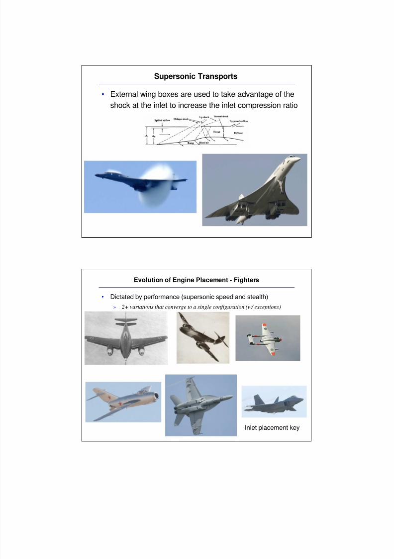
Supersonic Transports
• External wing boxes are used to take advantage of theshock at the inlet to increase the inlet compression ratio
Evolution of Engine Placement - Fighters
• Dictated by performance (supersonic speed and stealth)
» 2+ variations that converge to a single configuration (w/ exceptions)
Inlet placement key
8/8/2019 Propulsion Pt2
http://slidepdf.com/reader/full/propulsion-pt2 11/12
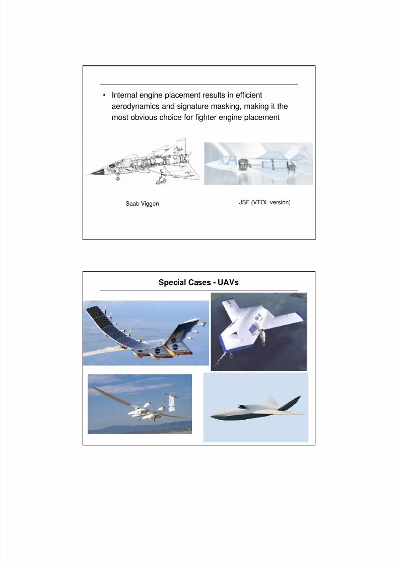
• Internal engine placement results in efficientaerodynamics and signature masking, making it the
most obvious choice for fighter engine placement
Saab Viggen JSF (VTOL version)
Special Cases - UAVs
8/8/2019 Propulsion Pt2
http://slidepdf.com/reader/full/propulsion-pt2 12/12
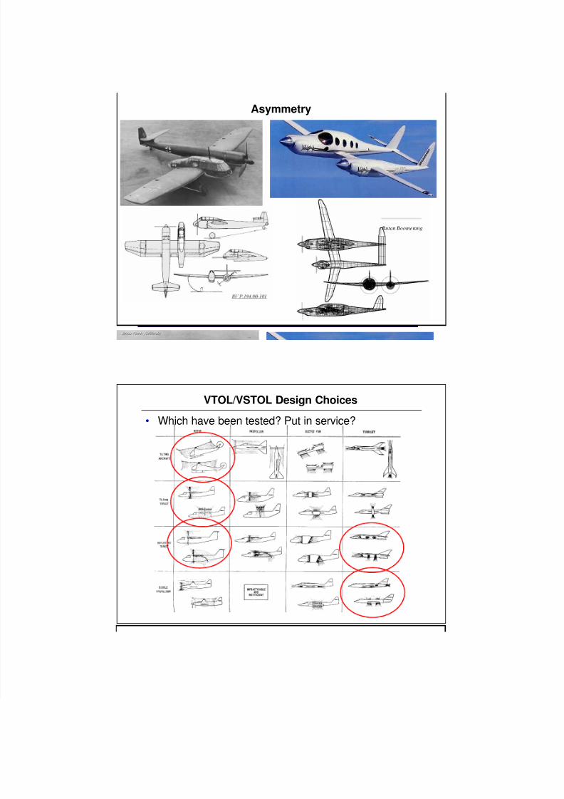
Asymmetry
Rutan Boomerang
VTOL/VSTOL Design Choices
• Which have been tested? Put in service?