PROPOSED UPGRADING OF OLOLULUNG'A DISTRICT HOSPITAL ... · republic of kenya ministry of health...
220
REPUBLIC OF KENYA MINISTRY OF HEALTH PROPOSED UPGRADING OF OLOLULUNG'A DISTRICT HOSPITAL - NAROK COUNTY ITEM NO. D108/ RV/NRK/1601 JOB. NO. 10199B PROJECT MANAGER WORKS SECRETARY MOTIH&UD -SDPW P.O. BOX 30743-00100 NAIROBI ARCHITECT QUANTITY SURVEYOR CHIEF ARCHITECT CHIEF QUANTITY SURVEYOR MOTIH&UD -SDPW MOTIH&UD -SDPW P.O. BOX 30743-00100 P.O. BOX 30743-00100 NAIROBI NAIROBI ELECTRICAL ENGINEER (B.S) MECHANICAL ENGINEER CHIEF ENGINEER (ELECT.)- (BS) CHIEF ENGINEER (MECH.)- (BS) MOTIH&UD -SDPW MOTIH&UD -SDPW P.O. BOX 30743-00100 P.O. BOX 30743-0010 NAIROBI NAIROBI STRUCTURAL ENGINEER CHIEF ENGINEER (STRUC) MOTIH&UD -SDPW P.O. BOX 30743-00100 NAIROBI AUGUST, 2017 TENDER DOCUMENTS
Transcript of PROPOSED UPGRADING OF OLOLULUNG'A DISTRICT HOSPITAL ... · republic of kenya ministry of health...

REPUBLIC OF KENYA
MINISTRY OF HEALTH
PROPOSED UPGRADING OF OLOLULUNG'A
DISTRICT HOSPITAL - NAROK COUNTY
ITEM NO. D108/ RV/NRK/1601 JOB. NO. 10199B
PROJECT MANAGER
WORKS SECRETARY MOTIH&UD -SDPW P.O. BOX 30743-00100 NAIROBI
ARCHITECT QUANTITY SURVEYOR CHIEF ARCHITECT CHIEF QUANTITY
SURVEYOR
MOTIH&UD -SDPW MOTIH&UD -SDPW
P.O. BOX 30743-00100 P.O. BOX 30743-00100
NAIROBI NAIROBI
ELECTRICAL ENGINEER (B.S) MECHANICAL ENGINEER
CHIEF ENGINEER (ELECT.)- (BS) CHIEF ENGINEER (MECH.)-
(BS)
MOTIH&UD -SDPW MOTIH&UD -SDPW
P.O. BOX 30743-00100 P.O. BOX 30743-0010
NAIROBI NAIROBI
STRUCTURAL ENGINEER
CHIEF ENGINEER (STRUC)
MOTIH&UD -SDPW
P.O. BOX 30743-00100
NAIROBI
AUGUST, 2017
TENDER DOCUMENTS
REPUBLIC OF KENYA
MINISTRY OF HEALTH
PROPOSED UPGRADING OF OLOLULUNG’A DISTRICT
HOSPITAL – NAROK COUNTY
CONTENTS
ITEM PAGE NO
1 Contents page (i)
2 Signature and Special notes page (ii)
SECTION ONE – STANDARD TENDER DOCUMENT
3 Instructions to Tenderers 3-18
4 Tender Evaluation criteria TEC/7
5 Conditions of contract 19-42
6 Appendix to conditions of contract 43-44
7 Specifications 45-46
8 Drawings 47
9 Bills of Quantities 48-50
10 Standard forms 51-71
SECTION TWO-PRELIMINARIES
11 Particular preliminaries Pg 8
12 General preliminaries Page 9
SECTION THREE-BILLS OF QUANTITIES
13 Builders Works Summary page BW SUMS/1
14 Mechanical Works Summary page C21
15 Electrical Works Summary page H/10
16 Provisional Sums page Prov Sums/1
17 Main Summary MS/1
(i)

REPUBLIC OF KENYA
MINISTRY OF HEALTH
PROPOSED UPGRADING OF OLOLULUNG’A
DISTRICT HOSPITAL – NAROK COUNTY.
Supplied as part of the Contract PROPOSED UPGRADING OF OLOLULUNG’A DISTRICT
HOSPITAL – NAROK COUNTY. W.P. ITEM NO. D108/ RV/NRK / 1601/ JOB NO 10199B.
Issued by:- Quantities and Contracts Department
Ministry of Transport, Infrastructure, Housing
and Urban Development.
(State Department of Public Works)
P O Box 30743– 00100
NAIROBI
The contract for the above mentioned works entered into this …….. day of …………………. 2017
by the undersigned refers to these Bills of Quantities and the Ministry of Public Works General
Specification date March , 1976 (together with any amendments issued thereto) shall be read and
construed as part of the said contract.
………………………………………… ………………………………………
C O N T R A C T O R PRINCIPAL SECRETARY
MINISTRY OF HEALTH
Date: ………………………… Date: ……………………………
SPECIAL NOTES
The Contractor is required to check the numbers of the pages of these Bills of Quantities and
should he find any missing or in duplicate or figures indistinct he must inform the Principal
Secretary for Ministry of Transport, Infrastructure, Housing and Urban Development (State
Department of Public Works) Head Office, Ngong Road, Nairobi at once and have the same
rectified.
Should the Contractor be in doubt about the precise meaning of any item or figure for any reason
whatsoever, he must inform the Principal Secretary, Ministry of Transport, Infrastructure, Housing
and Urban Development (State Department of Public Works) Head Office in order that the correct
meaning may be decided before the date for submission of tenders.
No liability will be admitted nor claim allowed in respect of errors in the Contractor’s Tender due
to mistakes in the Specifications which should have been rectified in the manner described above.
SIGNATURE PAGE AND NOTES
(ii)

REPUBLIC OF KENYA
STANDARD TENDER DOCUMENT
FOR
PROCUREMENT OF WORKS (BUILDING AND ASSOCIATED
CIVIL ENGINEERING WORKS)
PUBLIC PROCUREMENT OVERSIGHT AUTHORITY (PPOA)
P.O. BOX 30007 - 00200 NAIROBI.
(REVISED OCTOBER 2006)

2
TABLE OF CONTENTS
PAGE INTRODUCTION ………………………………………………
3
SECTION I: INVITATION TO TENDER …………………………………… 4
SECTION II: INSTRUCTIONS TO TENDERERS ……………………….. 5 - 18
SECTION III: CONDITIONS OF CONTRACT …………………………….. 19- 41
SECTION IV: APPENDIX TO CONDITIONS OF CONTRACT ……………………………………………………
42 - 43
SECTION V: SPECIFICATIONS …………………………………………… 44 - 45
SECTION VI: DRAWINGS …………………………………………………… 46
SECTION VII: BILLS OF QUANTITIES ……………………………………. 47 - 49
SECTION VIII: STANDARD FORMS ………………………………………… 50 - 69
3
INTRODUCTION
1.1 This standard tender document for procurement of works
has been prepared for use by procuring entities in Kenya in
the procurement of works (i.e. Buildings and associated Civil Engineering Works).
1.2 The following guidelines should be observed when using the document:-
(a) Specific details should be furnished in the Invitation to tender and in the special conditions of contract (where applicable). The tender document issued to tenderers
should not have blank spaces or options.
(b) The instructions to tenderers and the General Conditions of Contract should remain unchanged. Any necessary amendments to these parts should be made through
Appendix to instructions to tenderers and special conditions of contract respectively.
1.3 (b) Information contained in the invitation to tender shall
conform to the data and information in the tender documents to enable prospective tenderers to decide whether or not to participate in the tender and shall
indicate any important tender requirements
(c) The invitation to tender shall be as an advertisement in
accordance with the regulations or a letter of invitation addressed to tenderers who have been prequalified
following a request for prequalification. 1.4 The cover of the document shall be modified to include:-
I. Tender number.
II. Tender name. III. Name of procuring entity.

4
SECTION I
INVITATION FOR TENDERS
Tender Name: PROPOSED UPGRADING OF OLOLULUNG’A DISTRICT HOSPITAL – NAROK COUNTY AND ASSOCIATED ELECTRICAL,
MECHANICAL, CIVIL AND EXTERNAL WORKS
1.1 The Ministry of Health, Health Sector Equalization Fund Project invites sealed tenders for the Proposed Upgrading of Ololulung’a District Hospital – Narok county: Erection and Completion of Staff Houses and Associated Electrical, Mechanical, Civil and External Works.
1.2 Interested eligible candidates may obtain further information
and inspect tender documents at Ministry of Health Headquarters, P.O Box 30016 – 00100 Nairobi, located in Afya House, Cathedral Road off Ngong Road, Supply Chain Management office, 5th Floor, Room No.510B Nairobi during normal working hours.
1.3 A complete set of tender documents may be obtained by interested candidates upon payment of non-refundable fee of
Kshs.3,000 in cash or Bankers Cheque payable to the Principal Secretary, Ministry of Health.
1.4 Prices quoted should be net inclusive of all taxes, must be in Kenya shillings and shall remain valid for 150 days from the
closing date of tender. 1.5 Completed tender documents are to be enclosed in plain
sealed envelopes marked with Tender name and reference number and deposited in the Tender Box at Ministry of health, P.O Box 30016 – 00100 Nairobi, located in Afya House, Cathedral Road off Ngong Road, 1st Floor or to be
addressed to the Principal Secretary, Ministry of Health Po Box P.O Box 30016 – 00100 Nairobi so as to be received
on or before (As per the advert)..
1.6 Tenders will be opened immediately thereafter in the
presence of the candidates or their representatives who choose to attend at GTZ Boardroom, Ground floor, Afya house, Cathedral Road Off Ngong Road.
Head, Supply Chain Management Services
For Principal Secretary, Ministry of Health
5
SECTION II
INSTRUCTIONS TO TENDERERS
TABLE OF CONTENTS PAGE
CLAUSE PAGE
1. Contents Page …………………………………………. 5 2. General Eligibility………………………………………….. 6 - 9
3. Tender Documents ………………………………… 9 - 10
4. Preparation of Tenders ………………………………… 10 - 13
5. Submission of Tenders ………………………………… 13 - 14
6. Tende r Opening and Evaluation ……………………… 14 -
16 7. Award of Contract ………………………………………… 16 –
18 8. Corrupt Practices …………………………………………. 18

6
INSTRUCTIONS TO TENDERERS.
1. 1. General/Eligibility/Qualifications/Joint venture/Cost of tendering
1.1 The Employer as defined in the Appendix to Conditions of
Contract invites tenders for Works Contract as described in
the tender documents. The successful tenderer will be expected to complete the Works by the Intended Completion Date specified in the tender documents.
1.2 All tenderers shall provide the Qualification Information, a
statement that the tenderer (including all members of a joint venture and subcontractors) is not associated, or has not been associated in the past, directly or indirectly, with the
Consultant or any other entity that has prepared the design, specifications, and other documents for the project or being
proposed as Project Manager for the Contract. A firm that has been engaged by the Employer to provide consulting services for the preparation or supervision of the Works, and
any of its affiliates, shall not be eligible to tender.
1.3 All tenderers shall provide in the Form of Tender and
Qualification Information, a preliminary description of the proposed work method and schedule, including drawings
and charts, as necessary.
1.4 In the event that pre-qualification of potential tenderers has
been undertaken, only tenders from pre-qualified tenderers will be considered for award of Contract. These qualified tenderers should submit with their tenders any information
updating their original pre-qualification applications or, alternatively, confirm in their tenders that the originally
submitted pre-qualification information remains essentially correct as of the date of tender submission.
1.5 Where no pre-qualification of potential tenderers has been done, all tenderers shall include the following information
and documents with their tenders , unless otherwise stated:
(a) copies of original documents defining the constitution
or legal status, place of registration, and principal place of business; written power of attorney of the signatory of the tender to commit the tenderer:
(b) total monetary value of construction work performed
for each of the last five years:
(c) experience in works of a similar nature and size for
each of the last five years, and details of work under way or contractually committed; and names and
addresses of clients who may be contacted for further information on these contracts;
7
(d) major items of construction equipment proposed to
carry out the Contract and an undertaking that they will be available for the Contract.
(e) qualifications and experience of key site management and technical personnel proposed for the Contract and an undertaking that they shall be available for the
Contract.
(f) reports on the financial standing of the tenderer, such as profit and loss statements and auditor’s reports for the past five years;
(g) evidence of adequacy of working capital for this
Contract (access to line(s) of credit and availability of other financial resources);
(h) authority to seek references from the tenderer’s bankers;
(i) information regarding any litigation, current or during the last five years, in which the tenderer is involved,
the parties concerned and disputed amount; and
(j) proposals for subcontracting components of the Works
amounting to more than 10 percent of the Contract Price.
1.6 Tenders submitted by a joint venture of two or more firms as partners shall comply with the following requirements,
unless otherwise stated:
(a) the tender shall include all the information listed in
clause 1.5 above for each joint venture partner;
(b) the tender shall be signed so as to be legally binding
on all
partners;
(c) all partners shall be jointly and severally liable for the
execution of the Contract in accordance with the Contract terms;
(d) one of the partners will be nominated as being in
charge,
authorised to incur liabilities, and receive instructions for and on behalf of all partners of the joint venture;
and
8
(e) the execution of the entire Contract, including payment, shall be
done exclusively with the partner in charge.
1.7 To qualify for award of the Contract, tenderers shall meet the following minimum qualifying criteria;
(a) annual volume of construction work of at least 2.5 times the estimated annual cashflow for the Contract;
(b) experience as main contractor in the construction of at least
two works of a nature and complexity equivalent to the Works
over the last 10 years (to comply with this requirement,
works cited should be at least 70 percent complete);
(c) proposals for the timely acquisition (own, lease, hire, etc.) of the essential equipment listed as required for the Works;
(d) a Contract manager with at least five years’ experience in
works of an equivalent nature and volume, including no
less than three years as Manager; and
(e) liquid assets and/or credit facilities, net of other contractual commitments and exclusive of any advance payments which may be made under the Contract, of no
less than 4 months of the estimated payment flow under this Contract.
1.8 The figures for each of the partners of a joint venture shall be added together to determine the tenderer’s compliance with
the minimum qualifying criteria of clause 1.7 (a) and (e); however, for a joint venture to qualify, each of its partners must meet at least 25 percent of minimum criteria 1.7 (a), (b)
and (e) for an individual tenderer, and the partner in charge at least 40 percent of those minimum criteria. Failure to
comply with this requirement will result in rejection of the joint venture’s tender. Subcontractors’ experience and resources will not be taken into account in determining the
tenderer’s compliance with the qualifying criteria, unless otherwise stated.
1.9 Each tenderer shall submit only one tender, either individually or as a partner in a joint venture. A tenderer
who submits or participates in more than one tender (other than as a subcontractor or in cases of alternatives that have been permitted or requested) will cause all the proposals with
the tenderer’s participation to be disqualified.

9
1.10 The tenderer shall bear all costs associated with the preparation and submission of his tender, and the Employer
will in no case be responsible or liable for those costs.
1.11 The tenderer, at the tenderer’s own responsibility and risk, is encouraged to visit and examine the Site of the Works and its surroundings, and obtain all information that may be
necessary for preparing the tender and entering into a contract for construction of the Works. The costs of visiting the Site shall be at the tenderer’s own expense.
1.12 The procuring entity’s employees, committee members, board members and their relative (spouse and children) are not eligible to participate in the tender.
1.13 The price to be charged for the tender document shall not
exceed Kshs.5,000/=
1.14 The procuring entity shall allow the tenderer to review the
tender document free of charge before purchase.
2. Tender Documents
2.1 The complete set of tender documents comprises the documents listed below and any addenda issued in accordance with Clause 2.4.
(a) These Instructions to Tenderers (b) Form of Tender and Qualification Information
(c) Conditions of Contract (d) Appendix to Conditions of Contract
(e) Specifications (f) Drawings (g) Bills of Quantities
(h) Forms of Securities
2.2 The tenderer shall examine all Instructions, Forms to be filled and Specifications in the tender documents. Failure to furnish all information required by the tender documents, or
submission of a tender not substantially responsive to the tendering documents in every respect will be at the tenderer’s risk and may result in rejection of his tender.
2.3 A prospective tenderer making an inquiry relating to the
tender documents may notify the Employer in writing or by cable, telex or facsimile at the address indicated in the letter of invitation to tender. The Employer will only respond to
requests for clarification received earlier than seven days prior to the deadline for submission of tenders. Copies of the
Employer’s response will be forwarded to all persons issued
10
with tendering documents, including a description of the inquiry, but without identifying its source.
2.4 Before the deadline for submission of tenders, the Employer
may modify the tendering documents by issuing addenda. Any addendum thus issued shall be part of the tendering documents and shall be communicated in writing or by
cable, telex or facsimile to all tenderers. Prospective tenderers shall acknowledge receipt of each addendum in writing to the Employer.
2.5 To give prospective tenderers reasonable time in which to
take an addendum into account in preparing their tenders, the Employer shall extend, as necessary, the deadline for submission of tenders, in accordance with Clause 4.2 here
below.
3. Preparation of Tenders
3.1 All documents relating to the tender and any correspondence
shall be in English language.
3.2 The tender submitted by the tenderer shall comprise the
following:
(a) These Instructions to Tenderers, Form of Tender,
Conditions of Contract, Appendix to Conditions of Contract and Specifications;
(b) Tender Security;
(c) Priced Bill of Quantities ;
(d) Qualification Information Form and Documents;
(e) Alternative offers where invited; and
(f) Any other materials required to be completed and
submitted by the tenderers.
3.3 The tenderer shall fill in rates and prices for all items of the
Works described in the Bill of Quantities. Items for which no
rate or price is entered by the tenderer will not be paid for when executed and shall be deemed covered by the other
rates and prices in the Bill of Quantities. All duties, taxes, and other levies payable by the Contractor under the Contract, or for any other cause relevant to the Contract, as
of 30 days prior to the deadline for submission of tenders, shall be included in the tender price submitted by the
tenderer.
11
3.4 The rates and prices quoted by the tenderer shall only be subject to adjustment during the performance of the
Contract if provided for in the Appendix to Conditions of Contract and provisions made in the Conditions of Contract.
3.5 The unit rates and prices shall be in Kenya Shillings.
3.6 Tenders shall remain valid for a period of sixty (60) days from the date of submission. However in exceptional circumstances, the Employer may request that the tenderers
extend the period of validity for a specified additional period. The request and the tenderers’ responses shall be made in
writing. A tenderer may refuse the request without forfeiting the Tender Security. A tenderer agreeing to the request will not be required or permitted to otherwise modify the tender,
but will be required to extend the validity of Tender Security for the period of the extension, and in compliance with
Clause 3.7 - 3.11 in all respects.
3.7 The tenderer shall furnish, as part of the tender, a Tender
Security in the amount and form specified in the appendix to invitation to tenderers. This shall be in the amount not exceeding 2 percent of the tender price
3.8 The format of the Tender Security should be in accordance
with the form of Tender Security included in Section G - Standard forms or any other form acceptable to the Employer. Tender Security shall be valid for 30 days beyond
the validity of the tender.
3.9 Any tender not accompanied by an acceptable Tender
Security shall be rejected. The Tender Security of a joint venture must define as “Tenderer” all joint venture partners
and list them in the following manner: a joint venture consisting of “…………”, “…………”,and “…………”.
3.10 The Tender Securities of unsuccessful tenderers will be returned within 28 days of the end of the tender validity
period specified in Clause 3.6.
3.11 The Tender Security of the successful tenderer will be
discharged when the tenderer has signed the Contract Agreement and furnished the required Performance Security.
3.12 The Tender Security may be forfeited
(a) if the tenderer withdraws the tender after tender opening during the period of tender validity;
(b) if the tenderer does not accept the correction of the tender price, pursuant to Clause 5.7;

12
(c) in the case of a successful tenderer, if the tenderer fails within the specified time limit to
(i) sign the Agreement, or
(ii) furnish the required Performance Security.
3.13 Tenderers shall submit offers that comply with the requirements of the tendering documents, including the basic technical design as indicated in the Drawings and
Specifications. Alternatives will not be considered, unless specifically allowed in the invitation to tender. If so allowed,
tenderers wishing to offer technical alternatives to the requirements of the tendering documents must also submit a tender that complies with the requirements of the tendering
documents, including the basic technical design as indicated in the Drawings and Specifications. In addition to
submitting the basic tender, the tenderer shall provide all information necessary for a complete evaluation of the alternative, including design calculations, technical
specifications, breakdown of prices, proposed construction methods and other relevant details. Only the technical alternatives, if any, of
the lowest evaluated tender conforming to the basic technical requirements shall be considered.
3.14 The tenderer shall prepare one original of the documents
comprising the tender documents as described in Clause 3.2
of these Instructions to Tenderers, bound with the volume containing the Form of Tender, and clearly marked “ORIGINAL”. In addition, the tenderer
shall submit copies of the tender, in the number specified in the invitation to tender, and clearly marked as “COPIES”. In
the event of discrepancy between them, the original shall prevail.
3.15 The original and all copies of the tender shall be typed or written in indelible ink and shall be signed by a person or
persons duly authorised to sign on behalf of the tenderer, pursuant to Clause 1.5 (a) or 1.6 (b), as the case may be. All pages of the tender where alterations or additions have been
made shall be initialled by the person or persons signing the tender.
3.16 Clarification of tenders shall be requested by the tenderer to be received by the procuring entity not later than 7 days
prior to the deadline for submission of tenders.
3.17 The procuring entity shall reply to any clarifications sought by the tenderer within 3 days of receiving the request to
enable the tenderer to make timely submission of its tender.
13
3.18 The tender security shall be in the amount of 0.5 – 2 per cent of the tender price.
4. Submission of Tenders
4.1 The tenderer shall seal the original and all copies of the
tender in two inner envelopes and one outer envelope, duly
marking the inner envelopes as “ORIGINAL” and “COPIES” as appropriate. The inner and outer envelopes shall:
(a) be addressed to the Employer at the address provided in the invitation to tender;
(b) bear the name and identification number of the
Contract as defined in the invitation to tender; and
(c) provide a warning not to open before the specified time
and date for tender opening.
4.2 Tenders shall be delivered to the Employer at the address
specified above not later than the time and date specified in the invitation to tender. However, the Employer may extend the deadline for submission of tenders by issuing an
amendment in accordance with Sub-Clause 2.5 in which case all rights and obligations of the Employer and the
tenderers previously subject to the original deadline will then be subject to the new deadline.
4.3 Any tender received after the deadline prescribed in clause 4.2 will be returned to the tenderer un-opened.
4.4 Tenderers may modify or withdraw their tenders by giving notice in writing before the deadline prescribed in clause 4.2.
Each tenderer’s modification or withdrawal notice shall be prepared, sealed, marked, and delivered in accordance with clause 3.13 and 4.1, with
the outer and inner envelopes additionally marked “MODIFICATION”and “WITHDRAWAL”, as appropriate. No
tender may be modified after the deadline for submission of tenders.
4.5 Withdrawal of a tender between the deadline for submission of tenders and the expiration of the period of tender validity
specified in the invitation to tender or as extended pursuant to Clause 3.6 may result in the forfeiture of the Tender
Security pursuant to Clause 3.11.
4.6 Tenderers may only offer discounts to, or otherwise modify
the prices of their tenders by submitting tender modifications in accordance with Clause 4.4 or be included in the original
tender submission.
14
5. Tender Opening and Evaluation
5.1 The tenders will be opened by the Employer, including modifications made pursuant to Clause 4.4, in the presence
of the tenderers’ representatives who choose to attend at the time and in the place specified in the invitation to tender. Envelopes marked “WITHDRAWAL” shall be opened and
read out first. Tenderers’ and Employer’s representatives who are present during the opening shall sign a register evidencing their attendance.
5.2 The tenderers’ names, the tender prices, the total amount of
each tender and of any alternative tender (if alternatives have been requested or permitted), any discounts, tender modifications and withdrawals, the presence or absence of
Tender Security, and such other details as may be considered appropriate, will be announced by the Employer
at the opening. Minutes of the tender opening, including the information disclosed to those present will be prepared by the Employer.
5.3 Information relating to the examination, clarification,
evaluation, and comparison of tenders and recommendations
for the award of Contract shall not be disclosed to tenderers or any other persons not officially concerned with such
process until the award to the successful tenderer has been announced. Any effort by a tenderer to influence the Employer’s officials, processing of tenders or award decisions
may result in the rejection of his tender.
5.4 To assist in the examination, evaluation, and comparison of
tenders, the Employer at his discretion, may ask any tenderer for clarification of the tender, including breakdowns
of unit rates. The request for clarification and the response shall be in writing or by cable, telex or facsimile but no change in the price or substance of the tender shall be
sought, offered, or permitted except as required to confirm the correction of arithmetic errors discovered in the
evaluation of the tenders in accordance with Clause 5.7.
5.5 Prior to the detailed evaluation of tenders, the Employer will
determine whether each tender (a) meets the eligibility criteria defined in Clause 1.7;(b) has been properly signed; (c) is
accompanied by the required securities; and (d) is substantially responsive to the requirements of the tendering
documents. A substantially responsive tender is one which conforms to all the terms, conditions and specifications of the tendering documents, without material deviation or
reservation. A material deviation or reservation is one (a) which
15
affects in any substantial way the scope, quality, or
performance of the works; (b) which limits in any substantial way, inconsistent with the tendering documents, the
Employer’s rights or the tenderer’s obligations under the Contract; or (c) whose rectification would affect unfairly the competitive position of other tenderers presenting
substantially responsive tenders.
5.6 If a tender is not substantially responsive, it will be rejected,
and may not subsequently be made responsive by correction or withdrawal of the nonconforming deviation or reservation.
5.7 Tenders determined to be substantially responsive will be
checked for any arithmetic errors. Errors will be corrected as
follows:
(a) where there is a discrepancy between the amount in figures and the amount in words, the amount in words will prevail; and
(b) where there is a discrepancy between the unit rate and
the line item total resulting from multiplying the unit
rate by the quantity, the unit rate as quoted will prevail, unless in the opinion of the Employer, there is
an obvious typographical error, in which case the adjustment will be made to the entry containing that error.
(c) In the event of a discrepancy between the tender
amount as stated in the Form of Tender and the
corrected tender figure in the main summary of the Bill of Quantities, the amount as stated in the Form of
Tender shall prevail.
(d) The Error Correction Factor shall be computed by
expressing the difference between the tender amount and the corrected tender sum as a percentage of the
corrected Builder’s Work (i.e. Corrected tender sum less P.C. and Provisional Sums)
(e) The Error Correction Factor shall be applied to all Builder’s Work (as a rebate or addition as the case may be) for the purposes of valuations for Interim
Certificates and valuation of variations.
(f) the amount stated in the tender will be adjusted in accordance with the above procedure for the correction of errors and, with
concurrence of the tenderer, shall be considered as binding upon the tenderer. If the tenderer does not
accept the corrected amount, the tender may be

16
rejected and the Tender Security may be forfeited in accordance with clause 3.11.
5.8 The Employer will evaluate and compare only the tenders
determined to be substantially responsive in accordance with Clause 5.5.
5.9 In evaluating the tenders, the Employer will determine for each tender the evaluated tender price by adjusting the tender price as follows:
(a) making any correction for errors pursuant to clause
5.7;
(b) excluding provisional sums and the provision, if any,
for contingencies in the Bill of Quantities, but including Dayworks where priced competitively.
(c) making an appropriate adjustment for any other
acceptable variations, deviations, or alternative offers
submitted in accordance with clause 3.12; and
(d) making appropriate adjustments to reflect discounts or
other price modifications offered in accordance with clause 4.6
5.10 The Employer reserves the right to accept or reject any
variation, deviation, or alternative offer. Variations,
deviations, and alternative offers and other factors which are in excess of the requirements of the tender documents or otherwise result in unsolicited benefits for the Employer will
not be taken into account in tender evaluation.
5.11 The tenderer shall not influence the Employer on any matter
relating to his tender from the time of the tender opening to
the time the Contract is awarded. Any effort by the Tenderer to influence the Employer or his employees in his decision on
tender evaluation, tender comparison or Contract award may result in the rejection of the tender.
5.12 Firms incorporated in Kenya where indigenous Kenyans own 51% or more of the share capital shall be allowed a 10% preferential bias provided that they do not sub-contract work
valued at more than 50% of the Contract Price excluding Provisional Sums to an
Non-indigenous sub-contractor.
6. Award of Contract

17
6.1 Subject to Clause 6.2, the award of the Contract will be made to the tenderer whose tender has been determined to be
substantially responsive to the tendering documents and who has offered
the lowest evaluated tender price, provided that such tenderer has been determined to be (a) eligible in accordance with the provision of Clauses 1.2, and (b) qualified in
accordance with the provisions of clause 1.7 and 1.8.
6.2 Notwithstanding clause 6.1 above, the Employer reserves the
right to accept or reject any tender, and to cancel the tendering
process and reject all tenders, at any time prior to the award of Contract, without thereby incurring any liability to the affected tenderer or tenderers or any obligation to inform the
affected tenderer or tenderers of the grounds for the action.
6.3 The tenderer whose tender has been accepted will be notified of the award prior to expiration of the tender validity period in writing or by cable, telex or facsimile. This notification
(hereinafter and in all Contract documents called the “Letter of Acceptance”) will state the sum (hereinafter and in all Contract documents called the “Contract Price”)that the
Employer will pay the Contractor in consideration of the execution, completion, and maintenance of the Works by the
Contractor as prescribed by the Contract. At the same time the other tenderers shall be informed that their tenders have not been successful.
The contract shall be formed on the parties signing the contract.
6.4 The Agreement will incorporate all agreements between the
Employer and the successful tenderer. Within 14 days of receipt the successful tenderer will sign the Agreement and return it to the Employer.
6.5 Within 21 days after receipt of the Letter of Acceptance, the
successful tenderer shall deliver to the Employer a Performance Security in the amount stipulated in the Appendix to Conditions of Contract and in the form
stipulated in the Tender documents. The Performance Security shall be in the amount and specified form
6.6 Failure of the successful tenderer to comply with the requirements of clause 6.5 shall constitute sufficient grounds
for cancellation of the award and forfeiture of the Tender Security.
6.7 Upon the furnishing by the successful tenderer of the Performance Security, the Employer will promptly notify the
other tenderers that their tenders have been unsuccessful.

18
6.8 Preference where allowed in the evaluation of tenders shall not be allowed for contracts not exceeding one year (12
months)
6.9 The tender evaluation committee shall evaluate the tender within 30 days of the validity period from the date of opening the tender.
6.10 The parties to the contract shall have it signed within 30
days from the date of notification of contract award unless
there is an administrative review request.
6.11 Contract price variations shall not be allowed for contracts not exceeding one year (12 months)
6.12 Where contract price variation is allowed, the valuation shall not exceed 15% of the original contract price.
6.13 Price variation request shall be processed by the procuring
entity within 30 days of receiving the request.
6.14 The procuring entity may at any time terminate procurement
proceedings before contract award and shall not be liable to
any person for the termination.
6.15 The procuring entity shall give prompt notice of the termination to the tenderers and on request give its reasons for termination within 14 days of receiving the request from
any tenderer.
6.16 A tenderer who gives false information in the tender
document about its qualification or who refuses to enter into a contract after notification of contract award shall be
considered for debarment from participating in future public procurement.
7. Corrupt and Fraudulent practices
7.1 The procuring entity requires that tenderers observe the highest standards of ethics during procurement process and execution of contracts. A tenderer shall sign a declaration
that he has not and will not be involved in corrupt and fraudulent practices.
SECTION III CONDITIONS OF CONTRACT
Table of Contents
1 Definitions ………………………………………………… 21 - 22
2 Interpretation……………………………………………… 23
3 Language and Law ………………………………………… 24
4 Project Manager’s Decisions……………………………… 24

19
5 Delegation………………………………………………… 24
6 Communications ………………………………………… 24
7 Sub Contracting ………………………………………… 24
8 Other Contractors ……………………………………… 24
9 Personnel ………………………………………………… 24
10 Works……………………………………………………… 25
11 Safety and temporary works ……………………………… 25
12 Discoveries ………………………………………………… 25
13 Work Programme ………………………………………… 25 - 26
14 Possession of site ………………………………………… 26
15 Access to site …………………………………………… 26
16 Instructions ……………………………………………… 26
17 Extension or Acceleration of completion date ………… 26
18 Management Meetings ………………………………… 27
19 Early Warning …………………………………………… 27
20 Defects …………………………………………………… 27 - 28
21 Bills of Quantities ………………………………………… 28
22 Variations ………………………………………………… 28 - 29
23 Payment certificates, currency of payments and
Advance Payments ……………………………………… 29 - 31
24 Compensation events …………………………………… 31 - 33
25 Price Adjustment ………………………………………… 33 - 34
26 Retention ………………………………………………… 34
27 Liquidated Damages……………………………………… 34
28 Securities ………………………………………………… 35
29 Day Works ……………………………………………… 35
30 Liability and Insurance …………………………………… 35 - 36
31 Completion and taking over ……………………………… 37
32 Final Account …………………………………………… 37
33 Termination ……………………………………………… 37 - 38
34 Payment upon termination ………………………………… 38 - 39
35 Release from performance ………………………………… 39
36 Corrupt gifts and payments of commission ………………39
37 Settlement of Disputes ……………………………………… 39 - 41

20
CONDITIONS OF CONTRACT
1. Definitions
1.1 In this Contract, except where context otherwise requires, the following terms shall be interpreted as indicated;

21
“Bill of Quantities” means the priced and completed Bill of Quantities forming part of the tender.
“Compensation Events” are those defined in Clause 24
hereunder. “The Completion Date” means the date of completion of the
Works as certified by the Project Manager, in accordance with Clause 31.
“The Contract” means the agreement entered into between the Employer and the Contractor as recorded in the
Agreement Form and signed by the parties including all attachments and appendices thereto and all documents incorporated by reference therein to execute, complete, and
maintain the Works,
“The Contractor” refers to the person or corporate body whose tender to carry out the Works has been accepted by the Employer.
“The Contractor’s Tender”is the completed tendering document submitted by the Contractor to the Employer.
“The Contract Price” is the price stated in the Letter of
Acceptance and thereafter as adjusted in accordance with the provisions of the Contract.
“Days” are calendar days; “Months” are calendar months. “A Defect” is any part of the Works not completed in
accordance with the Contract.
“The Defects Liability Certificate” is the certificate issued by Project Manager upon correction of defects by the Contractor.
“The Defects Liability Period” is the period named in the
Contract Data and calculated from the Completion Date. “Drawings” include calculations and other information
provided or approved by the Project Manager for the execution of the Contract.
“Dayworks” are Work inputs subject to payment on a time basis for labour and the associated materials and plant.
“Employer”, or the “Procuring entity” as defined in the Public Procurement Regulations (i.e. Central or Local
Government administration, Universities, Public Institutions and Corporations, etc) is the party who employs the
Contractor to carry out the Works.

22
“Equipment” is the Contractor’s machinery and vehicles brought temporarily to the Site for the execution of the
Works.
“The Intended Completion Date” is the date on which it is intended that the Contractor shall complete the Works. The Intended Completion Date may be revised only by the Project
Manager by issuing an extension of time or an acceleration order.
“Materials” are all supplies, including consumables, used by the Contractor for incorporation in the Works.
“Plant” is any integral part of the Works that shall have a mechanical, electrical, chemical, or biological function.
“Project Manager” is the person named in the Appendix to
Conditions of Contract (or any other competent person appointed by the Employer and notified to the Contractor, to act in replacement of the Project Manager) who is responsible
for supervising the execution of the Works and administering the Contract and shall be an “Architect” or a “Quantity Surveyor” registered under the Architects and Quantity
Surveyors Act Cap 525 or an “Engineer” registered under Engineers Registration Act Cap 530.
“Site” is the area defined as such in the Appendix to Condition of Contract.
“Site Investigation Reports” are those reports that may be included in the tendering documents which are factual and
interpretative about the surface and subsurface conditions at the Site.
“Specifications” means the Specifications of the Works included in the Contract and any modification or addition
made or approved by the Project Manager.
“Start Date” is the latest date when the Contractor shall commence execution of the Works. It does not necessarily coincide with the Site possession date(s).
“A Subcontractor” is a person or corporate body who has a Contract with the Contractor to carry out a part of the Work
in the Contract, which includes Work on the Site.
“Temporary works” are works designed, constructed, installed, and removed by the Contractor which are needed for construction or installation of the Works.
“A Variation” is an instruction given by the Project Manager which
varies the Works.

23
“The Works” are what the Contract requires the Contractor to construct, install, and turnover to the Employer, as defined in the
Appendix to Conditions of Contract.
2. Interpretation
2.1 In interpreting these Conditions of Contract, singular also
means plural, male also means female or neuter, and the other way around. Headings have no significance. Words have their normal meaning in English Language unless
specifically defined. The Project Manager will provide instructions clarifying queries about these Conditions of
Contract.
2.2 If sectional completion is specified in the Appendix to
Conditions of Contract, reference in the Conditions of Contract to the Works, the Completion Date and the
Intended Completion Date apply to any section of the Works (other than references to the Intended Completion Date for the whole of the Works).
2.3 The following documents shall constitute the Contract
documents and shall be interpreted in the following order of
priority;
(1) Agreement,
(2) Letter of Acceptance,
(3) Contractor’s Tender,
(4) Appendix to Conditions of Contract,
(5) Conditions of Contract,
(6) Specifications,
(7) Drawings,
(8) Bill of Quantities,
(9) Any other documents listed in the Appendix to Conditions of Contract as forming part of the Contract.
Immediately after the execution of the Contract, the Project Manager
shall furnish both the Employer and the Contractor with two copies each of all the Contract documents. Further, as and when
necessary the Project Manager shall furnish the Contractor [always
with a copy

24
to the Employer] with three [3] copies of such further drawings or
details or descriptive schedules as are reasonably necessary either
to explain or amplify the Contract drawings or to enable the Contractor to carry out and complete the Works in accordance with
these Conditions. 3. Language and Law
3.1 Language of the Contract and the law governing the Contract
shall be English language and the Laws of Kenya respectively unless
otherwise stated.
4 Project Manager’s Decisions
4.1 Except where otherwise specifically stated, the Project
Manager will decide contractual matters between the
Employer and the Contractor in the role representing the Employer.
5 Delegation
5.1 The Project Manager may delegate any of his duties and responsibilities to others after notifying the Contractor.
6 Communications
6.1 Communication between parties shall be effective only when
in writing. A notice shall be effective only when it is delivered.
7 Subcontracting
7.1 The Contractor may subcontract with the approval of the Project Manager, but may not assign the Contract without
the approval of the Employer in writing. Subcontracting shall not alter the Contractor’s obligations.
8 Other Contractors 8.1 The Contractor shall cooperate and share the Site with other
contractors, public authorities, utilities etc. as listed in the Appendix to Conditions of Contract and also with the
Employer, as per the directions of the Project Manager. The Contractor shall also provide facilities and services for them. The Employer may modify the said List of Other Contractors
etc., and shall notify the Contractor of any such modification.
9 Personnel

25
9.1 The Contractor shall employ the key personnel named in the
Qualification Information, to carry out the functions stated in the said Information or other personnel approved by the
Project Manager. The Project Manager will approve any proposed replacement of key personnel only if their relevant qualifications and abilities are substantially equal to or
better than those of the personnel listed in the Qualification Information. If the Project Manager asks the Contractor to remove a person who is a member of the Contractor’s staff or
work force, stating the reasons, the Contractor shall ensure that the person leaves the Site within seven days and has no
further connection with the Work in the Contract. 10 Works
10.1 The Contractor shall construct and install the Works in
accordance with the Specifications and Drawings. The Works may commence on the Start Date and shall be carried out in accordance with the Program submitted by the
Contractor, as updated with the approval of the Project Manager, and complete them by the Intended Completion Date.
11 Safety and Temporary Works
11.1 The Contractor shall be responsible for the design of
temporary works. However before erecting the same, he
shall submit his designs including specifications and drawings to the Project Manager and to any other relevant third parties for their approval. No erection of temporary
works shall be done until such approvals are obtained.
11.2 The Project Manager’s approval shall not alter the Contractor’s responsibility for design of the Temporary works and all drawings prepared by the Contractor for the
execution of the temporary or permanent Works, shall be subject to prior approval by the Project Manager before they
can be used.
11.3 The Contractor shall be responsible for the safety of all
activities on the Site. 12. Discoveries
12.1 Anyth ing of historical or other interest or of significant value
unexpectedly discovered on Site shall be the property of the Employer. The Contractor shall notify the Project Manager of such discoveries and carry out the Project Manager’s
instructions for dealing with them.
13. Work Program
26
13.1 Within the time stated in the Appendix to Conditions of Contract, the Contractor shall submit to the Project Manager
for approval a program showing the general methods, arrangements, order, and timing for all the activities in the
Works. An update of the program shall be a program showing the actual progress achieved on each activity and the effect of the progress achieved on the timing of the
remaining Work, including any changes to the sequence of the activities.
The Contractor shall submit to the Project Manager for approval an updated program at intervals no longer than the
period stated in the Appendix to Conditions of Contract. If the Contractor does not submit an updated program within this period, the Project Manager
may withhold the amount stated in the said Appendix from the next payment certificate and continue to withhold this
amount until the next payment after the date on which the overdue program has been submitted. The Project Manager’s approval of the program shall not alter the Contractor’s
obligations. The Contractor may revise the program and submit it to the Project Manager again at any time. A revised program shall show the effect of Variations and
Compensation Events.
14. Possession of Site
14.1 The Employer shall give possession of all parts of the Site to
the Contractor. If possession of a part is not given by the date stated in the Appendix to Conditions of Contract, the Employer will be deemed to have delayed the start of the
relevant activities, and this will be a Compensation Event.
15. Access to Site
15.1 The Contractor shall allow the Project Manager and any
other person authorised by the Project Manager, access to the Site and to any place where work in connection with the
Contract is being carried out or is intended to be carried out. 16. Instructions
16.1 The Contractor shall carry out all instructions of the Project
Manager which are in accordance with the Contract.
17. Extension or Acceleration of Completion Date
17.1 The Project Manager shall extend the Intended Completion
Date if a Compensation Event occurs or a variation is issued
which makes it impossible for completion to be achieved by the Intended Completion Date without the Contractor taking
steps to accelerate the remaining Work, which would cause the Contractor to incur additional cost. The Project Manager

27
shall decide whether and by how much to extend the Intended Completion Date within 21 days of the Contractor
asking the Project Manager in writing for a decision upon the effect of a Compensation Event or variation and submitting
full supporting information. If the Contractor has failed to give early warning of a delay or has failed to cooperate in dealing with a delay, the delay caused by such failure shall
not be considered in assessing the new (extended) Completion Date.
17.2 No bonus for early completion of the Works shall be paid to the Contractor by the Employer.
18. Management Meetings
18.1 A Contract management meeting shall be held monthly and
attended by the Project Manager and the Contractor. Its business shall be to review the plans for the remaining Work and to deal with matters raised in accordance with the early
warning procedure. The Project Manager shall record the minutes of management meetings and provide copies of the same to those attending the meeting and the Employer. The
responsibility of the parties for actions to be taken shall be decided by the Project Manager either at the management
meeting or after the management meeting and stated in writing to all who attended the meeting.
19. Early Warning 19.1 The Contractor shall warn the Project Manager at the earliest
opportunity of specific likely future events or circumstances that may adversely affect the quality of the Work increase the
Contract Price or delay the execution of the Works. The Project Manager may require the Contractor to provide an estimate of the expected effect of the future event or
circumstance on the Contract Price and Completion Date. The estimate shall be provided by the Contractor as soon as
reasonably possible. 19.2 The Contractor shall cooperate with the Project Manager in
making and considering proposals on how the effect of such an event or circumstance can be avoided or reduced by anyone involved in the Work and in carrying out any
resulting instructions of the Project Manager.
20. Defects
20.1 The Project Manager shall inspect the Contractor’s work and
notify the Contractor of any defects that are found. Such inspection shall not affect the Contractor’s responsibilities.
The Project Manager may instruct the Contractor to search for a defect and to uncover and test any Work that the

28
Project Manager considers may have a defect. Should the defect be found, the cost of uncovering and making good
shall be borne by the Contractor, However, if there is no defect found, the cost of uncovering and making good shall
be treated as a variation and added to the Contract Price.
20.2 The Project Manager shall give notice to the Contractor of
any defects before the end of the Defects Liability Period, which begins at Completion, and is defined in the Appendix to Conditions of
Contract. The Defects Liability Period shall be extended for as long as defects remain to be corrected.
20.3 Every time notice of a defect is given, the Contractor shall
correct the notified defect within the length of time specified
by the Project Manager’s notice. If the Contractor has not corrected a defect within the time specified in the Project
Manager’s notice, the Project Manager will assess the cost of having the defect corrected by other parties and such cost shall be treated as a variation and be deducted from the
Contract Price. 21. Bills Of Quantities
21.1 The Bills of Quantities shall contain items for the
construction, installation, testing and commissioning of the Work to be done by the Contractor. The Contractor will be paid for the quantity of the Work done at the rate in the Bills
of Quantities for each item.
21.2 If the final quantity of the Work done differs from the
quantity in the Bills of Quantities for the particular item by more than 25 percent and provided the change exceeds 1
percent of the Initial Contract price, the Project Manager shall adjust the rate to allow for the change.
21.3 If requested by the Project Manager, the Contractor shall provide the Project Manager with a detailed cost breakdown
of any rate in the Bills of Quantities. 22. Variations
22.1 All variations shall be included in updated programs
produced by the Contractor.
22.2 The Contractor shall provide the Project Manager with a quotation for carrying out the variations when requested to do so. The Project Manager shall assess the quotation,
which shall be given within seven days of the request or within any longer period as may be stated by the Project
Manager and before the Variation is ordered.

29
22.3 If the work in the variation corresponds with an item
description in the Bills of Quantities and if in the opinion of the Project Manager, the quantity of work is not above the
limit stated in Clause 21.2 or the timing of its execution does not cause the cost per unit of quantity to change, the rate in the Bills of Quantities shall be used to calculate the value of
the variation. If the cost per unit of quantity changes, or if the nature or timing of the work in the variation does not correspond with items in the Bills of Quantities, the
quotation by the Contractor shall be in the form of new rates for the relevant items of Work.
22.4 If the Contractor’s quotation is unreasonable, the Project
Manager may order the variation and make a change to the Contract price, which shall be based on the Project
Manager’s own forecast of the effects of the variation on the Contractor’s costs.
22.5 If the Project Manager decides that the urgency of varying the
Work would prevent a quotation being given and considered
without delaying the Work, no quotation shall be given and the variation shall be treated as a Compensation Event.
22.6 The Contractor shall not be entitled to additional payment
for costs that could have been avoided by giving early warning.
22.7 When the Program is updated, the Contractor shall provide
the Project Manager with an updated cash flow forecast. 23. Payment Certificates, Currency of Payments and Advance
Payments
23.1 The Contractor shall submit to the Project Manager monthly applications for payment giving sufficient details of the Work done and materials on Site and the amounts which the
Contractor considers himself to be entitled to. The Project Manager shall check the monthly application and certify the amount to be paid to the Contractor within 14 days. The
value of Work executed and payable shall be determined by the Project Manager.
23.2 The value of Work executed shall comprise the value of the
quantities of the items in the Bills of Quantities completed; materials delivered on Site, variations and compensation
events. Such materials shall become the property of the Employer once the Employer has paid the Contractor for

30
their value. Thereafter, they shall not be removed from Site without the Project Manager’s instructions except for use
upon the Works.
23.3 Payments shall be adjusted for deductions for retention. The
Employer shall pay the Contractor the amounts certified by
the Project Manager within 30 days of the date of issue of each certificate. If the Employer makes a late payment, the Contractor shall be paid simple interest on the late payment
in the next payment. Interest shall be calculated on the basis of number of days delayed at a rate three percentage
points above the Central Bank of Kenya’s average rate for base lending prevailing as of the first day the payment becomes overdue.
23.4 If an amount certified is increased in a later certificate or as a result of an award by an Arbitrator, the Contractor shall be paid interest upon the delayed payment as set out in this
clause. Interest shall be calculated from the date upon which the increased amount would have been certified in the absence of dispute.
23.5 Items of the Works for which no rate or price has been entered in will not be paid for by the Employer and shall be deemed covered by other rates and prices in the Contract.
23.6 The Contract Price shall be stated in Kenya Shillings. All
payments to the Contractor shall be made in Kenya Shillings
and foreign currency in the proportion indicated in the tender, or agreed prior to the execution of the Contract
Agreement and indicated therein. The rate of exchange for the calculation of the amount of foreign currency payment shall be the rate of exchange indicated in the Appendix to
Conditions of Contract. If the Contractor indicated foreign currencies for payment other than the currencies of the
countries of origin of related goods and services the Employer reserves the right to pay the equivalent at the time of payment in the currencies of the countries of such goods and
services. The Employer and the Project Manager shall be notified promptly by the Contractor of an changes in the expected foreign currency requirements of the Contractor
during the execution of the Works as indicated in the Schedule of Foreign Currency Requirements and the foreign
and local currency portions of the balance of the Contract Price shall then be amended by agreement between Employer and the Contractor in order to reflect appropriately such
changes.
23.7 In the event that an advance payment is granted, the following shall apply:-
31
a) On signature of the Contract, the Contractor shall at
his request, and without furnishing proof of expenditure, be entitled to an advance of 10% (ten
percent) of the original amount of the Contract. The advance shall not be subject to retention money.
b) No advance payment may be made before the Contractor has submitted proof of the establishment of deposit or a directly
liable guarantee satisfactory to the Employer in the amount of the advance payment. The guarantee shall
be in the same currency as the advance.
c) Reimbursement of the lump sum advance shall be
made by deductions from the Interim payments and where applicable from the balance owing to the
Contractor. Reimbursement shall begin when the amount of the sums due under the Contract reaches 20% of the original amount of the Contract. It shall
have been completed by the time 80% of this amount is reached.
The amount to be repaid by way of successive deductions shall be calculated by means of the formula:
R = A(x1 – x11)
80 – 20
Where: R = the amount to be reimbursed
A = the amount of the advance which has been
granted
X1 = the amount of proposed cumulative
payments as a percentage of the original amount of the Contract. This figure will
exceed 20% but not exceed 80%. X11 = the amount of the previous cumulative
payments as a percentage of the original amount of the Contract. This figure will be below 80%but not less than 20%.
d) with each reimbursement the counterpart of the
directly liable guarantee may be reduced accordingly.
24. Compensation Events
24.1 The following issues shall constitute Compensation Events:

32
(a) The Employer does not give access to a part of the Site by the Site Possession Date stated in the Appendix to
Conditions of Contract.
(b) The Employer modifies the List of Other Contractors, etc., in a way that affects the Work of the Contractor under the Contract.
(c) The Project Manager orders a delay or does not issue
drawings, specifications or instructions required for
execution of the Works on time.
(d) The Project Manager instructs the Contractor to uncover or to carry out additional tests upon the Work, which is then found to have no defects.
(e) The Project Manager unreasonably does not approve a
subcontract to be let.
(f) Ground conditions are substantially more adverse
than could reasonably have been assumed before issuance of the Letter of Acceptance from the information issued to tenderers (including the Site
investigation reports), from information available publicly and from a visual inspection of the Site.
(g) The Project Manager gives an instruction for dealing
with an unforeseen condition, caused by the Employer
or additional work required for safety or other reasons.
(h) Other contractors, public authorities, utilities, or the
Employer does not work within the dates and other constraints stated in the Contract, and they cause
delay or extra cost to the Contractor.
(i) The effects on the Contractor of any of the Employer’s
risks.
(j) The Project Manager unreasonably delays issuing a Certificate of Completion.
(k) Other compensation events described in the Contract or determined by the Project Manager shall apply.
24.2 If a compensation event would cause additional cost or would prevent the Work being completed before the Intended
Completion Date, the Contract Price shall be increased and/or the Intended Completion Date shall be extended. The Project Manager shall decide whether and by how much the
Contract Price shall be increased and whether and by how much the Intended Completion Date shall be extended.
33
24.3 As soon as information demonstrating the effect of each compensation event upon the Contractor’s forecast cost has
been provided by the Contractor, it shall be assessed by the Project Manager, and the Contract Price shall be adjusted
accordingly. If the Contractor’s forecast is deemed unreasonable, the Project Manager shall adjust the Contract Price based on the Project Manager’s own forecast. The
Project Manager will assume that the Contractor will react competently and promptly to the event.
24.4 The Contractor shall not be entitled to compensation to the extent that the Employer’s interests are adversely affected by
the Contractor not having given early warning or not having co-operated with the Project Manager.
24.5 Prices shall be adjusted for fluctuations in the cost of inputs only if provided for in the Appendix to Conditions of
Contract.
24.6 The Contractor shall give written notice to the Project
Manager of his intention to make a claim within thirty days after the event giving rise to the claim has first arisen. The claim shall be submitted within thirty days thereafter.
Provided always that should the event giving rise to the claim of continuing effect, the Contractor shall submit an interim claim within the said thirty days and a final claim within
thirty days of the end of the event giving rise to the claim. 25. Price Adjustment
25.1 The Project Manager shall adjust the Contract Price if taxes,
duties and other levies are changed between the date 30 days before the submission of tenders for the Contract and the date of Completion. The adjustment shall be the change
in the amount of tax payable by the Contractor.
25.2 The Contract Price shall be deemed to be based on exchange rates current at the date of tender submission in calculating the cost to the Contractor of materials to be specifically
imported (by express provisions in the Contract Bills of Quantities or Specifications) for permanent incorporation in the Works. Unless otherwise stated in the Contract, if at any
time during the period of the Contract exchange rates shall be varied and this shall affect the cost to the Contractor of
such materials, then the Project Manager shall assess the net difference in the cost of such materials. Any amount from time to time so assessed shall be added to or deducted
from the Contract Price, as the case may be.
25.3 Unless otherwise stated in the Contract, the Contract Price shall be deemed to have been calculated in the manner set
34
out below and in sub-clauses 25.4 and 25.5 and shall be subject to adjustment in the events specified thereunder;
(i) The prices contained in the Contract Bills of Quantities
shall be deemed to be based upon the rates of wages and other emoluments and expenses as determined by the Joint
Building Council of Kenya (J.B.C.) and set out in the schedule of basic rates issued 30 days before the date for submission of tenders. A copy of the schedule used
by the Contractor in his pricing shall be attached in the Appendix to Conditions of Contract.
(ii) Upon J.B.C. determining that any of the said rates of
wages or other emoluments and expenses are
increased or decreased, then the Contract Price shall be increased or decreased by the amount assessed by
the Project Manager based upon the difference, expressed as a percentage, between the rate set out in the schedule of basic rates issued 30 days before
the date for submission of tenders and the rate published by the J.B.C. and applied to the quantum of labour incorporated within the amount of Work
remaining to be executed at the date of publication of such increase or decrease.
(iii) No adjustment shall be made in respect of changes in
the rates of wages and other emoluments and
expenses which occur after the date of Completion except during such other period as may be granted as an extension of time under clause 17.0 of these
Conditions.
25.4 The prices contained in the Contract Bills of Quantities shall be deemed to be based upon the basic prices of materials to be permanently incorporated in the Works as determined by
the J.B.C. and set out in the schedule of basic rates issued 30 days before the date for submission of tenders. A copy of
the schedule used by the Contractor in his pricing shall be attached in the Appendix to Conditions of Contract.
25.5 Upon the J.B.C. determining that any of the said basic prices are increased or decreased then the Contract Price shall be increased or decreased by the amount to be assessed by the
Project Manager based upon the difference between the price set out in the schedule of basic rates issued 30 days before
the date for submission of tenders and the rate published by the J.B.C. and applied to the quantum of the relevant materials which have not been taken into account in arriving
at the amount of any interim certificate under clause 23 of these Conditions issued before the date of publication of
such increase or decrease.
35
25.6 No adjustment shall be made in respect of changes in basic prices of materials which occur after the date for Completion
except during such other period as may be granted as an extension of time under clause 17.0 of these Conditions.
25.7 The provisions of sub-clause 25.1 to 25.2 herein shall not
apply in respect of any materials included in the schedule of basic rates.
26. Retention
26.1 The Employer shall retain from each payment due to the Contractor the proportion stated in the Appendix to Conditions of Contract until Completion of the whole of the
Works. On Completion of the whole of the Works, half the total amount retained shall be repaid to the Contractor and
the remaining half when the Defects Liability Period has passed and the Project Manager has certified that all defects notified to the Contractor before the end of this period have
been corrected. 27. Liquidated Damages
27.1 The Contractor shall pay liquidated damages to the Employer
at the rate stated in the Appendix to Conditions of Contract for each day that the actual Completion Date is later than the Intended Completion Date. The Employer may deduct
liquidated damages from payments due to the Contractor. Payment of liquidated damages shall not alter the Contractor’s liabilities.
27.2 If the Intended Completion Date is extended after liquidated
damages have been paid, the Project Manager shall correct any overpayment of liquidated damages by the Contractor by adjusting the next payment certificate. The Contractor shall
be paid interest on the overpayment, calculated from the date of payment to the date of repayment, at the rate
specified in Clause 23.30 28. Securities
28.1 The Performance Security shall be provided to the Employer
no later than the date specified in the Letter of Acceptance
and shall be issued in an amount and form and by a reputable bank acceptable to the Employer, and
denominated in Kenya Shillings. The Performance Security shall be valid until a date 30 days beyond the date of issue of the Certificate of Completion.
29. Dayworks

36
29.1 If applicable, the Dayworks rates in the Contractor’s tender shall be used for small additional amounts of Work only
when the Project Manager has given written instructions in advance for additional work to be paid for in that way.
29.2 All work to be paid for as Dayworks shall be recorded by the
Contractor on Forms approved by the Project Manager. Each
completed form shall be verified and signed by the Project Manager within two days of the Work being done.
29.3 The Contractor shall be paid for Dayworks subject to obtaining signed Dayworks forms.
30. Liability and Insurance
30.1 From the Start Date until the Defects Correction Certificate has been issued, the following are the Employer’s risks:
(a) The risk of personal injury, death or loss of or damage
to property (excluding the Works, Plant, Materials and
Equipment), which are due to;
(i) use or occupation of the Site by the Works or for
the purpose of the Works, which is the unavoidable result of the Works, or
(ii) negligence, breach of statutory duty or
interference with any legal right by the Employer
or by any person employed by or contracted to him except the Contractor.
(b) The risk of damage to the Works, Plant, Materials, and
Equipment to the extent that it is due to a fault of the Employer or in Employer’s design, or due to war or radioactive contamination directly affecting the place
where the Works are being executed.
30.2 From the Completion Date until the Defects Correction Certificate has been issued, the risk of loss of or damage to the Works, Plant, and Materials is the Employer’s risk except
loss or damage due to;
(a) a defect which existed on or before the Completion
Date.
(b) an event occurring before the Completion Date, which was not itself the Employer’s risk
(c) the activities of the Contractor on the Site after the Completion Date.

37
30.3 From the Start Date until the Defects Correction Certificate has been issued, the risks of personal injury, death and loss
of or damage to property (including, without limitation, the Works, Plant, Materials, and Equipment) which are not
Employer’s risk are Contractor’s risks.
The Contractor shall provide, in the joint names of the
Employer and the Contractor, insurance cover from the Start Date to the end of the Defects Liability Period, in the amounts stated in the Appendix to Conditions of Contract for
the following events; (a) loss of or damage to the Works, Plant, and Materials;
(b) loss of or damage to Equipment; (c) loss of or damage to property (except the Works, Plant,
Materials, and Equipment) in connection with the
Contract, and (d) personal injury or death.
30.4 Policies and certificates for insurance shall be delivered by
the Contractor to the Project Manager for the Project
Manager’s approval before the Start Date. All such insurance shall provide for compensation required to rectify the loss or damage incurred.
30.5 If the Contractor does not provide any of the policies and
certificates required, the Employer may effect the insurance which the Contractor should have provided and recover the premiums from payments otherwise due to the Contractor
or, if no payment is due, the payment of the premiums shall be a debt due.
30.6 Alterations to the terms of insurance shall not be made without the approval of the Project Manager. Both parties
shall comply with any conditions of insurance policies.
31. Completion and taking over 31.1 Upon deciding that the Works are complete, the Contractor
shall issue a written request to the Project Manager to issue a Certificate of Completion of the Works. The Employer shall take over the Site and the Works within seven [7] days
of the Project Manager’s issuing a Certificate of Completion.
32. Final Account 32.1 The Contractor shall issue the Project Manager with a
detailed account of the total amount that the Contractor considers payable to him by the Employer under the
Contract before the end of the Defects Liability Period. The Project Manager shall issue a Defects Liability Certificate and
38
certify any final payment that is due to the Contractor within 30 days of receiving the Contractor’s account if it is correct
and complete. If it is not, the Project Manager shall issue within 30 days a schedule that states the scope of the
corrections or additions that are necessary. If the final account is still unsatisfactory after it has been resubmitted, the Project Manager shall decide on the amount payable to
the Contractor and issue a Payment Certificate. The Employer shall pay the Contractor the amount due in the Final Certificate within 60 days.
33. Termination
33.1 The Employer or the Contractor may terminate the Contract
if the other party causes a fundamental breach of the
Contract. These
fundamental breaches of Contract shall include, but shall not be limited to, the following;
(a) the Contractor stops work for 30 days when no stoppage of work is shown on the current program and the stoppage has not been authorized by the Project
Manager;
(b) the Project Manager instructs the Contractor to delay the progress of the Works, and the instruction is not withdrawn within 30 days;
(c) the Contractor is declared bankrupt or goes into
liquidation other than for a reconstruction or
amalgamation;
(d) a payment certified by the Project Manager is not paid by the Employer to the Contractor within 30 days (for Interim Certificate) or 60 days (for Final Certificate)of
issue.
(e) the Project Manager gives notice that failure to correct a particular defect is a fundamental breach of Contract and the Contractor fails to correct it within a
reasonable period of time determined by the Project Manager;
(f) the Contractor does not maintain a security, which is required.
33.2 When either party to the Contract gives notice of a breach of
Contract to the Project Manager for a cause other than those
listed under Clause 33.1 above, the Project Manager shall decide whether the breach is fundamental or not.
39
33.3 Notwithstanding the above, the Employer may terminate the Contract for convenience.
33.4 If the Contract is terminated, the Contractor shall stop work
immediately, make the Site safe and secure, and leave the Site as soon as reasonably possible. The Project Manager shall immediately thereafter arrange for a meeting for the
purpose of taking record of the Works executed and materials, goods, equipment and temporary buildings on Site.
34. Payment Upon Termination
34.1 If the Contract is terminated because of a fundamental
breach of Contract by the Contractor, the Project Manager
shall issue a certificate for the value of the Work done and materials ordered and delivered to Site up to the date of the
issue of the certificate. Additional liquidated damages shall not apply. If the total amount due to the Employer exceeds any payment due to the Contractor, the difference shall be a
debt payable by the Contractor. 34.2 If the Contract is terminated for the Employer’s convenience
or because of a fundamental breach of Contract by the Employer, the Project Manager shall issue a certificate for
the value of the Work done, materials ordered, the reasonable cost of removal of equipment, repatriation of the Contractor’s personnel employed solely on the
Works, and the Contractor’s costs of protecting and securing the Works.
34.3 The Employer may employ and pay other persons to carry out and complete the Works and to rectify any defects and
may enter upon the Works and use all materials on the Site, plant, equipment and temporary works.
34.4 The Contractor shall, during the execution or after the completion of the Works under this clause remove from the
Site as and when required, within such reasonable time as the Project Manager may in writing specify, any temporary buildings, plant, machinery, appliances, goods or materials
belonging to or hired by him, and in default the Employer may (without being responsible for any loss or damage) remove and sell any such property of the Contractor, holding
the proceeds less all costs incurred to the credit of the Contractor.
Until after completion of the Works under this clause the Employer shall not be bound by any other provision of this Contract to make any payment to the Contractor, but upon
such completion as aforesaid and the verification within a reasonable time of the accounts therefore the Project
Manager shall certify the amount of expenses properly incurred by the Employer and, if such amount added to the
40
money paid to the Contractor before such determination exceeds the total amount which would have been payable on
due completion in accordance with this Contract the difference shall be a debt payable to the Employer by the
Contractor; and if the said amount added to the said money be less than the said total amount, the difference shall be a debt payable by the Employer to the Contractor.
35. Release from Performance
35.1 If the Contract is frustrated by the outbreak of war or by any other event entirely outside the control of either the
Employer or the Contractor, the Project Manager shall certify that the Contract has been frustrated. The Contractor shall make the Site safe and stop Work as quickly as possible after
receiving this certificate and shall be paid for all Work carried out before receiving it.
36. Corrupt gifts and payments of commission
The Contractor shall not; (a) Offer or give or agree to give to any person in the service of
the
Employer any gift or consideration of any kind as an inducement or reward for doing or forbearing to do or for having done or forborne to do any act in relation to the
obtaining or execution of this or any other Contract for the Employer or for showing or forbearing to show favour or disfavour to any person in relation to this or any other
contract for the Employer.
(b) Enter into this or any other contract with the Employer in connection with which commission has been paid or agreed to be paid by him or on his behalf or to his knowledge,
unless before the Contract is made particulars of any such commission and of the terms and conditions of any
agreement for the payment thereof have been disclosed in writing to the Employer.
Any breach of this Condition by the Contractor or by anyone employed by him or acting on his behalf (whether with or without the knowledge of the Contractor) shall be an offence
under the provisions of the Public Procurement Regulations issued under The Exchequer and Audit Act Cap 412 of the
Laws of Kenya. 37. Settlement Of Disputes
37.1 In case any dispute or difference shall arise between the
Employer or the Project Manager on his behalf and the Contractor, either during the progress or after the completion

41
or termination of the Works, such dispute shall be notified in writing by either party to the other with a request to submit
it to arbitration and to concur in the appointment of an Arbitrator within thirty days of the notice. The dispute shall
be referred to the arbitration and final decision of a person to be agreed between the parties. Failing agreement to concur in the appointment of an Arbitrator, the Arbitrator shall be
appointed by the Chairman or Vice Chairman of any of the following professional institutions;
(i) Architectural Association of Kenya
(ii) Institute of Quantity Surveyors of Kenya
(iii) Association of Consulting Engineers of Kenya
(iv) Chartered Institute of Arbitrators (Kenya Branch)
(v) Institution of Engineers of Kenya
On the request of the applying party. The institution written to first by the aggrieved party shall take precedence over all other institutions.
37.2 The arbitration may be on the construction of this Contract or on any matter or thing of whatsoever nature arising thereunder or in connection therewith, including any matter
or thing left by this Contract to the discretion of the Project Manager, or the withholding by the Project Manager of any certificate to which the Contractor may claim to be entitled to
or the measurement and valuation referred to in clause 23.0 of these conditions, or the rights and liabilities of the parties
subsequent to the termination of Contract. 37.3 Provided that no arbitration proceedings shall be commenced
on any dispute or difference where notice of a dispute or difference has not been given by the applying party within
ninety days of the occurrence or discovery of the matter or issue giving rise to the dispute.
37.4 Notwithstanding the issue of a notice as stated above, the arbitration of such a dispute or difference shall not commence unless an attempt has in the first instance been
made by the parties to settle such dispute or difference amicably with or without the assistance of third parties.
Proof of such attempt shall be required.
37.5 Notwithstanding anything stated herein the following matters
may be referred to arbitration before the practical completion of the Works or abandonment of the Works or termination of
the Contract by either party:

42
37.5.1 The appointment of a replacement Project Manager
upon the said person ceasing to act.
37.5.2 Whether or not the issue of an instruction by the Project
Manager is empowered by these Conditions.
37.5.3 Whether or not a certificate has been improperly
withheld
or is not in accordance with these Conditions.
37.5.4 Any dispute or difference arising in respect of war risks
or war damage.
37.6 All other matters shall only be referred to arbitration after
the completion or alleged completion of the Works or termination or alleged termination of the Contract, unless the Employer and the Contractor agree otherwise in writing.
37.7 The Arbitrator shall, without prejudice to the generality of his
powers, have powers to direct such measurements,
computations, tests or valuations as may in his opinion be desirable in order to determine the rights of the parties and
assess and award any sums which ought to have been the subject of or included in any certificate.
37.8 The Arbitrator shall, without prejudice to the generality of his powers,
have powers to open up, review and revise any certificate, opinion, decision, requirement or notice and to determine all
matters in dispute which shall be submitted to him in the same manner as if no such certificate, opinion, decision requirement or notice had been given.
37.9 The award of such Arbitrator shall be final and binding upon
the parties.

43
SECTION IV – APPENDIX TO CONDITIONS OF CONTRACT
THE EMPLOYER IS Name: MINISTRY OF HEALTH
Address: P.O BOX 30016 - 00100 NAIROBI
Name of Authorized Representative: PRINCIPAL SECRETARY
Telephone: 020-2717077
Facsimile: 020-2713750 The Project Manager is
Name: WORKS SECRETARY MOTIH&UD-STATE DEPARTMENT OF PUBLIC WORKS
Address: P.O BOX 30743 -00100 NAIROBI
Telephone: +254-02723101
Facsimile:
The name (and identification number) of the Contract is PROPOSED UPGRADING OF OLOLULUNG’A DISTRICT HOSPITAL – NAROK COUNTY. W.P. ITEM NO. D108/ RV/NRK / 1601/ JOB NO 10199B.
The Works consist of PROPOSED UPGRADING OF OLOLULUNG’A DISTRICT HOSPITAL – NAROK COUNTY: ERECTION AND COMPLETION OF STAFF HOUSES AND ASSOCIATED ELECTRICAL,
MECHANICAL, CIVIL AND EXTERNAL WORKS.
The Start Date shall be AGREED WITH THE PROJECT MANAGER
The Intended Completion Date for the whole of the Works shall be THIRTY TWO (32) WEEKS AFTER COMMENCEMENT DATE
The following documents also form part of the Contract: Documents listed in clause 2.1 conditions of contract
The Contractor shall submit a revised program for the Works within Seven (7No) days of delivery of the Letter of Acceptance.
The Site Possession Date shall be AGREED WITH THE PROJECT
MANAGER. The Site is located at OLOLULUNG’A DISPENSARY-NAROK COUNTY
and is defined in drawings nos (AS ATTACHED) The Defects Liability period is 180 days.

44
Other Contractors, utilities etc., to be engaged by the Employer on the
Site Include those for the execution of; NONE
The minimum insurance covers shall be;
1. The minimum cover for insurance of the Works and of Plant and Materials in respect of the Contractor’s faulty design is the entire contract
2. The minimum cover for loss or damage to Equipment is Kshs
2,000,000 3. The minimum for insurance of other property is Kshs 5,000,000
4. The minimum cover for personal injury or death insurance
For the Contractor’s employees is AS PER THE
APPLICABLE LAWS IN KENYA
And for other people is Kshs 5,000,000
The following events shall also be Compensation Events:
Those listed in the conditions of contract. The period between Program updates is thirty (30No) days.
The amount to be withheld for late submission of an updated Program is
N/A The proportion of payments retained is Ten (10%) percent.
The Price Adjustment Clause (SHALL NOT) apply
The liquidated damages for the whole of the Works is Kshs. 50,000.00 (Per Week)
The Performance Security shall be for the following minimum amounts equivalent as a percentage of the Contract Price- Five (5%) percent.
The Completion Period for the Works is THIRTY TWO (32) WEEKS.
The rate of exchange for calculation of foreign currency payments is NOT APPLICABLE.
Advance Payment shall not be granted.
45
SECTION V - SPECIFICATIONS
Notes for preparing Specifications
1.0 Specifications must be drafted to present a clear
and precise statement of the required standards of
materials,
and workmanship for tenderers to respond realistically and competitively to the
requirements of the Employer and ensure responsiveness of tenders. The Specifications should require that all materials, plant, and
other supplies to be permanently incorporated in the Works be new, unused, of the most recent or current models, and incorporating all recent
improvements in design and materials unless provided otherwise in the Contract. Where the
Contractor is responsible for the design of any part of the permanent Works, the extent of his obligations must be stated.
2.0 Specifications from previous similar projects are
useful and may not be necessary to re-write
specifications for every Works Contract.
3.0 There are considerable advantages in standardizing General Specifications for repetitive Works in recognized public sectors,
such as highways, urban housing, irrigation and water supply. The General Specifications should
cover all classes of workmanship, materials and equipment commonly involved in constructions, although not necessarily to be used in a
particular works contract. Deletions or addenda should then adapt the General Specifications to the particular Works.
4.0 Care must be taken in drafting Specifications to
ensure they are not restrictive. In the Specifications of standards for materials, plant and workmanship, existing Kenya Standards
should be used as much as possible, otherwise recognized international standards may also be
used.
5.0 The Employer should decide whether technical
solutions to specified parts of the Works are to be permitted. Alternatives are appropriate in cases where obvious (and potentially less costly)
alternatives are possible to the technical solutions indicated in tender documents for
certain elements of the Works, taking into
46
consideration the comparative specialized advantage of potential tenderers.
The Employer should provide a description of the selected parts of the Works with appropriate reference to Drawings, Specifications, Bills of
Quantities, and Design or Performance criteria, stating that the alternative solutions shall be at least structurally and functionally equivalent to
the basic design parameters and Specifications.
Such alternative solutions shall be accompanied by all information necessary for a complete evaluation by the Employer, including drawings,
design calculations, technical specifications, breakdown of prices, proposed construction
methodology, and other relevant details. Technical alternatives permitted in this manner shall be considered by the Employer each on its
own merits and independently of whether the tenderer has priced the item as described in the Employer’s design included with the tender
documents.

47
SECTION VI - DRAWINGS
1. A list of drawings
i. Sectional Elevations ii. Ground floor plans
iii. First floor plan iv. Site plan v. Roof plan
48
SECTION VII - BILL OF QUANTITIES
Notes for preparing Bills of Quantities
1.0 The objectives of the Bills of Quantities are;
(a) To provide sufficient information on the quantities of Works to be performed to enable tenders to be prepared efficiently
and accurately; and
(b) When a Contract has been entered into, to provide a priced Bill of Quantities for use in the periodic valuation of Works
executed.
In order to attain these objectives, Works should be itemized in the Bill of Quantities in sufficient detail to distinguish
between the different classes of Works, or between Works of the same nature carried out in different locations or in other
circumstances which may give rise to different considerations of cost. Consistent with these requirements, the layout and content of the Bill of Quantities should be as
simple and brief as possible.
2.0 The Bills of Quantities should be divided generally into the following sections:
(a) Preliminaries.
The preliminaries should indicate the inclusiveness of the
unit prices, and should state the methods of measurement which have been adopted in the preparation of the Bill of
Quantities and which are to be used for the measurement of any part of the Works.
The number of preliminary items to be priced by the tenderer should be limited to tangible items such as site office and
other temporary works, otherwise items such as security for the Works which are primarily part of the Contractor’s obligations should be included in the Contractor’s rates.
(b) Work Items
(i) The items in the Bills of Quantities should be grouped into sections to distinguish between those parts of the
Works which by nature, location, access, timing, or any other special characteristics may give rise to different methods of construction, or phasing of the
Works, or considerations of cost. General items common to all parts of the Works may be grouped as a
separate section in the Bill of Quantities.

49
(ii) Quantities should be computed net from the Drawings,
unless directed otherwise in the Contract, and no allowance should be made for bulking, shrinkage or
waste. Quantities should be rounded up or down where appropriate.
(iii) The following units of measurement and abbreviations are recommended for use.
Unit Abbreviation Unit Abbreviation
cubic meter hectare hour
kilogram lump sum meter metric ton (1,000 kg)
m3 or cu m
ha
h kg
sum
m
t
millimeter month number
square meter square millimeter week
mm mon nr
m2 or sq m mm2 or sq mm wk
(iv) The commencing surface should be identified in the description of each item for Work involving excavation, boring or drilling, for which the
commencing surface is not also the original surface. The excavated surface should be identified in the description of each item for
Work involving excavation for which the excavated surface is not also the final surface.
The depths of Work should be measured from the commencing surface to the excavated surface, as defined.
(c) Daywork Schedule
A Daywork Schedule should be included if the probability of
unforeseen work, outside the items included in the Bill of Quantities, is relatively high. To facilitate checking by the Employer of the
realism of rates quoted by the tenderers, the Daywork Schedule should normally comprise:
(i) a list of the various classes of labour, and materials for which basic Day work rates or
prices are to be inserted by the tenderer, together with a statement of the conditions under which the Contractor will be paid for
Work executed on a Day work basis; and
(ii) a percentage to be entered by the tenderer
against each basic Day work Subtotal amount for labour, materials and plant representing the
Contractor’s profit, overheads, supervision and other charges.
50
(d) Provisional Quantities and Sums
i. Provision for quantity contingencies in any particular item or class of Work with a high expectation of quantity overrun should be made by entering specific “Provisional Quantities”
or “Provisional Items” in the Bill of Quantities, and not by increasing the quantities for that item or class of Work
beyond those of the Work normally expected to be required. To the extent covered above, a general provision or physical contingencies (quantity overruns) should be made by
including a “Provisional Sum” in the Summary of the Bill of Quantities. Similarly, a contingency allowance for possible
price increases should be provided as a “Provisional Sum” in the Summary of the Bill of Quantities. The inclusion of such provisional sums often facilitates budgetary approval by
avoiding the need to request periodic supplementary approvals as the future need arises.
ii. Provisional sums to cover specialized works normally carried
out by Nominated Sub Contractors should be avoided and
instead Bills of Quantities of the specialised Works should be included as a section of the main Bills of Quantities to be priced by the Main Contractor. The Main Contractor should
be required to indicate the name (s) of the specialised firms he proposes to engage to carry out the specialized Works as
his approved domestic sub-contractors. Only provisional sums to cover specialized Works by statutory authorities should be included in the Bills of Quantities.
(e) Summary
The Summary should contain a tabulation of the
separate parts of the Bills of Quantities carried
forward, with provisional sums for Daywork, for physical (quantity) contingencies, and for price
contingencies (upward price adjustment) where applicable.
51
SECTION VIII – STANDARD FORM
(i) Form of Invitation for Tenders
(ii) Form of Tender (iii) Letter of Acceptance (iv) Form of Agreement (v) Form of Tender Security (vi) Performance Bank Guarantee (vii) Bank Guarantee for Advance Payment (viii) Qualification Information (ix) Tender Questionnaire (xi) Confidential Business Questionnaire (x) Statement of Foreign Currency Requirement (xi) Details of Sub-Contractors

52
FORM OF INVITATION FOR TENDERS
_______________________[date] To: _____________________________________ [name of Contractor] _____________________________________[address] _____________________________________ _____________________________________
Dear Sirs:
Reference:______________________________________________[Contract Name] You have been prequalified to tender for the above project.
We hereby invite you and other prequalified tenderers to submit a tender
for the execution and completion of the above Contract. A complete set of tender documents may be purchased by you from ____
________________________________________________________________________ [mailing address, cable/telex/facsimile numbers]. Upon payment of a non-refundable fee of Kshs __________________________
All tenders must be accompanied by ________________number of copies of the same and a security in the form and amount specified in the tendering documents, and must be delivered to
________________________________________________________________________ [address and location] at or before _______________________(time and date). Tenders will be opened immediately thereafter, in the presence of tenderers’
representatives who choose to attend.
Please confirm receipt of this letter immediately in writing by cable/facsimile or telex.
Yours faithfully, _____________________________________ Authorised Signature
_____________________________________ Name and Title

53
FORM OF TENDER
TO: __________________________[Name of Employer) ____________[Date] __________________________[Name of Contract] Dear Sir,
1. In accordance with the Conditions of Contract, Specifications,
Drawings and Bills of Quantities for the execution of the above
named Works, we, the undersigned offer to construct, install and complete such Works and remedy any defects therein for the sum
of Kshs._____________________________[Amount in figures]Kenya Shillings___________________________________________________________________________________________[Amount in words]
2. We undertake, if our tender is accepted, to commence the Works as
soon as is reasonably possible after the receipt of the Project Manager’s notice to commence, and to complete the whole of the Works comprised in the Contract within the time stated in the
Appendix to Conditions of Contract.
3. We agree to abide by this tender until ___________________[Insert date], and it shall remain binding upon us and may be accepted at
any time before that date. 4. Unless and until a formal Agreement is prepared and executed this
tender together with your written acceptance thereof, shall constitute a binding Contract between us.
5. We understand that you are not bound to accept the lowest or any tender you may receive.
Dated this ____________________ day of _______20________________
Signature __________________in the capacity of___________________
duly authorized to sign tenders for and on behalf of _____________________________________________[Name of Employer] of___________________________________________[Address of Employer] Witness; Name______________________________________
Address_____________________________________
Signature___________________________________ Date_______________________________________

54
LETTER OF ACCEPTANCE [letterhead paper of the Employer] _______________________[date]
To: _______________________ [name of the Contractor]
_____________________
[address of the Contractor]
Dear Sir,
This is to notify you that your Tender dated ___________________________ for the execution of ________________________________________________
[name of the Contract and identification number,as given in the Tender documents] for the Contract Price of Kshs. __________________________ [amount in figures][Kenya Shillings______________________________(amount in words) ] in accordance with the Instructions to Tenderers is hereby accepted.
You are hereby instructed to proceed with the execution of the said
Works in accordance with the Contract documents. Authorized Signature …………………………………………………………………
Name and Title of Signatory
………………………………………………………… Attachment : Agreement

55
FORM OF AGREEMENT
THIS AGREEMENT, made the _________________ day of ________ 20 ______ between________________________________________________of[or whose
registered office is situated at]__________________________________________ (hereinafter called “the Employer”) of the one part AND ________________________________________________________of[or whose
registered office is situated at]_________________________________________ (hereinafter called “the Contractor”) of the other part.
WHEREAS THE Employer is desirous that the Contractor executes ________________________________________________________________________
(name and identification number of Contract ) (hereinafter called “the Works”) located at______________________________[Place/location of the
Works]and the Employer has accepted the tender submitted by the Contractor for the execution and completion of such Works and the
remedying of any defects therein for the Contract Price of Kshs___________________________[Amount in figures],Kenya Shillings_____________________________________________[Amount in words]. NOW THIS AGREEMENT WITNESSETH as follows:
1. In this Agreement, words and expressions shall have the same
meanings as are respectively assigned to them in the Conditions of
Contract hereinafter referred to.
2. The following documents shall be deemed to form and shall be read and construed as part of this Agreement i.e.
(i) Letter of Acceptance
(ii) Form of Tender
(iii) Conditions of Contract Part I
(iv) Conditions of Contract Part II and Appendix to Conditions of
Contract
(v) Specifications
(vi) Drawings
(vii) Priced Bills of Quantities
3. In consideration of the payments to be made by the Employer to the Contractor as hereinafter mentioned, the Contractor hereby
covenants with the Employer to execute and complete the Works
and remedy any defects therein in conformity in all respects with the provisions of the Contract.
4. The Employer hereby covenants to pay the Contractor in
consideration of the execution and completion of the Works and the

56
remedying of defects therein, the Contract Price or such other sum
as may become payable under the provisions of the Contract at the times and in the manner prescribed by the Contract.
IN WITNESS whereof the parties thereto have caused this Agreement to be executed the day and year first before written.
The common Seal of _____________________________________________
Was hereunto affixed in the presence of ________________________________
Signed Sealed, and Delivered by the said
Binding Signature of Employer ________________________________________
Witness
Binding Signature of Witness _______________________________________ Binding Signature of Contractor _______________________________________
In the presence of (i) Name_______________________________________ Address_____________________________________
Signature___________________________________
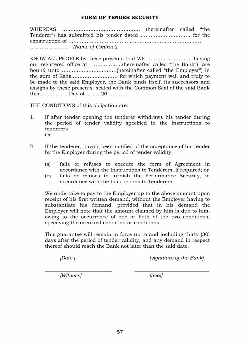
57
FORM OF TENDER SECURITY
WHEREAS ……………………………………….. (hereinafter called “the Tenderer”) has submitted his tender dated ………………………… for the
construction of ……………………………………………………………………… …………………… (Name of Contract)
KNOW ALL PEOPLE by these presents that WE ……………………… having our registered office at ………………(hereinafter called “the Bank”), are
bound unto ……………………………(hereinafter called “the Employer”) in the sum of Kshs.……………………… for which payment well and truly to be made to the said Employer, the Bank binds itself, its successors and
assigns by these presents sealed with the Common Seal of the said Bank this ……………. Day of ………20…………
THE CONDITIONS of this obligation are:
1. If after tender opening the tenderer withdraws his tender during the period of tender validity specified in the instructions to tenderers
Or
2. If the tenderer, having been notified of the acceptance of his tender by the Employer during the period of tender validity:
(a) fails or refuses to execute the form of Agreement in accordance with the Instructions to Tenderers, if required; or
(b) fails or refuses to furnish the Performance Security, in
accordance with the Instructions to Tenderers;
We undertake to pay to the Employer up to the above amount upon receipt of his first written demand, without the Employer having to substantiate his demand, provided that in his demand the
Employer will note that the amount claimed by him is due to him, owing to the occurrence of one or both of the two conditions, specifying the occurred condition or conditions.
This guarantee will remain in force up to and including thirty (30)
days after the period of tender validity, and any demand in respect thereof should reach the Bank not later than the said date.
___________________________ ______________________________
[Date [ [signature of the Bank] ___________________________ ______________________________ [Witness] [Seal]

58
PERFORMANCE BANK GUARANTEE To: _________________________(Name of Employer) ___________(Date) __________________________(Address of Employer)
Dear Sir, WHEREAS ______________________(hereinafter called “the Contractor”) has
undertaken, in pursuance of Contract No. _____________ dated _________ to execute _______________ (hereinafter called “the Works”);
AND WHEREAS it has been stipulated by you in the said Contract that the Contractor shall furnish you with a Bank Guarantee by a recognised
bank for the sum specified therein as security for compliance with his obligations in accordance with the Contract;
AND WHEREAS we have agreed to give the Contractor such a Bank Guarantee:
NOW THEREFORE we hereby affirm that we are the Guarantor and responsible to you, on behalf of the Contractor, up to a total of Kshs.
________________ (amount of Guarantee in figures) Kenya Shillings__________________________________________ (amount of Guarantee in words), and we undertake to pay you, upon your first written demand and without cavil or argument, any sum or sums within the limits of
Kenya Shillings _________________________ (amount of Guarantee in words) as aforesaid without your needing to prove or to show grounds or reasons for your demand for the sum specified therein.
We hereby waive the necessity of your demanding the said debt from the
Contractor before presenting us with the demand. We further agree that no change, addition or other modification of the
terms of the Contract or of the Works to be performed thereunder or of any of the Contract documents which may be made between you and the
Contractor shall in any way release us from any liability under this Guarantee, and we hereby waive notice of any change, addition, or modification.
This guarantee shall be valid until the date of issue of the Certificate of Completion.
SIGNATURE AND SEAL OF THE GUARANTOR ___________________
Name of Bank ____________________________________________
Address ________________________________________________
Date ______________________________________________________
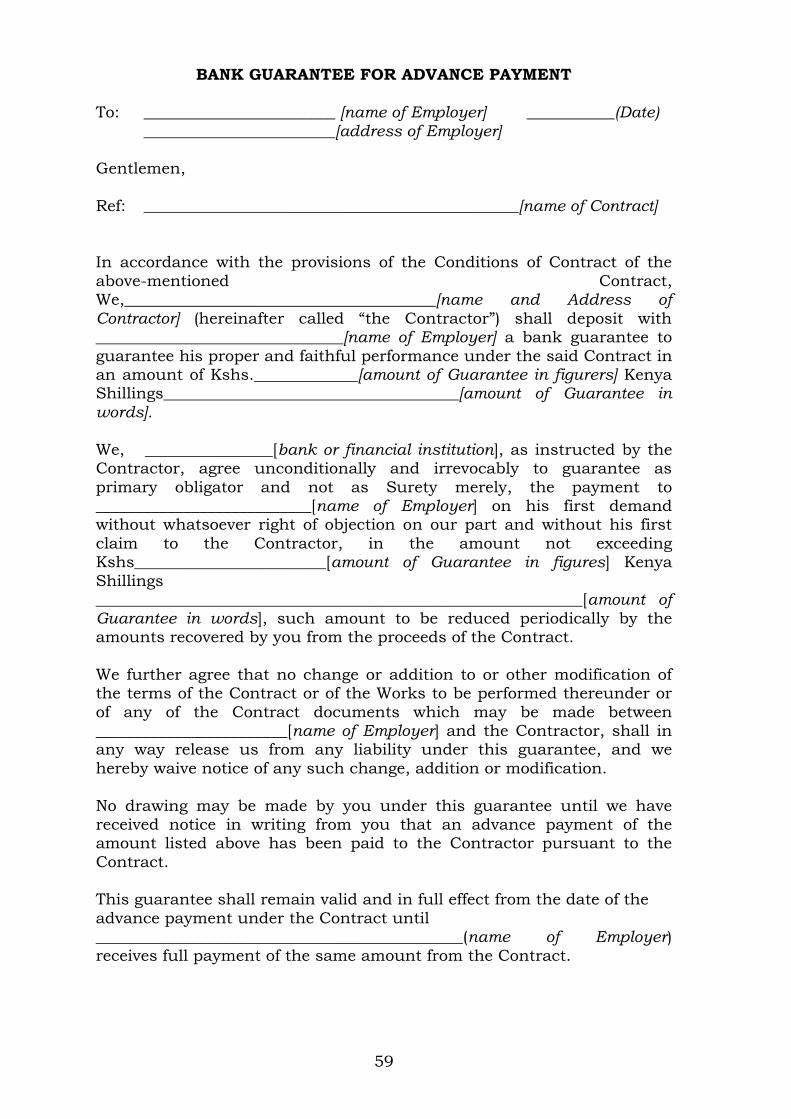
59
BANK GUARANTEE FOR ADVANCE PAYMENT
To: ________________________ [name of Employer] ___________(Date) ________________________[address of Employer] Gentlemen,
Ref: _______________________________________________[name of Contract] In accordance with the provisions of the Conditions of Contract of the
above-mentioned Contract, We,_______________________________________[name and Address of
Contractor] (hereinafter called “the Contractor”) shall deposit with _______________________________[name of Employer] a bank guarantee to
guarantee his proper and faithful performance under the said Contract in an amount of Kshs._____________[amount of Guarantee in figurers] Kenya Shillings_____________________________________[amount of Guarantee in words].
We, ________________[bank or financial institution], as instructed by the Contractor, agree unconditionally and irrevocably to guarantee as
primary obligator and not as Surety merely, the payment to ___________________________[name of Employer] on his first demand without whatsoever right of objection on our part and without his first
claim to the Contractor, in the amount not exceeding Kshs________________________[amount of Guarantee in figures] Kenya
Shillings _____________________________________________________________[amount of Guarantee in words], such amount to be reduced periodically by the amounts recovered by you from the proceeds of the Contract.
We further agree that no change or addition to or other modification of the terms of the Contract or of the Works to be performed thereunder or
of any of the Contract documents which may be made between ________________________[name of Employer] and the Contractor, shall in any way release us from any liability under this guarantee, and we
hereby waive notice of any such change, addition or modification.
No drawing may be made by you under this guarantee until we have received notice in writing from you that an advance payment of the amount listed above has been paid to the Contractor pursuant to the
Contract. This guarantee shall remain valid and in full effect from the date of the
advance payment under the Contract until ______________________________________________(name of Employer) receives full payment of the same amount from the Contract.

60
Yours faithfully,
Signature and Seal __________________________________________________ Name of the Bank or financial institution ______________________________
Address ______________________________________________________________
Date _________________________________________________________________
Witness: Name: ____________________________________________________ Address: __________________________________________________
Signature: ________________________________________________
Date: _____________________________________________________

61
QUALIFICATION INFORMATION 1. Individual Tenderers or Individual Members of Joint Ventures
1.1 Constitution or legal status of tenderer (attach copy or Incorporation Certificate); Place of registration: ____________________________
Principal place of business _____________________________
Power of attorney of signatory of tender ____________________
1.2 Total annual volume of construction work performed in the last five years
Year Volume
Currency Value
1.3 Work performed as Main Contractor on works of a similar
nature and volume over the last five years. Also list details of work under way or committed, including expected
completion date. Project name Name of client Type of work Value of
and contact performed and Contract person year of
completion
_________ ___________ __________ ________ _________ ___________ __________ ________
________ __________ __________ _______
1.4 Major items of Contractor’s Equipment proposed for carrying
out the Works. List all information requested below.
Item of Equipment
Description, Make and age
(years)
Condition(new, good, poor) and
number available
Owned, leased (from whom?),
or to be purchased
(from whom?)
_________
_________ _________(etc.)
____________
________________________
___________
______________________
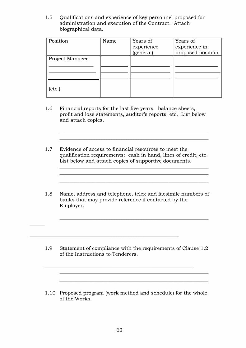
62
1.5 Qualifications and experience of key personnel proposed for administration and execution of the Contract. Attach
biographical data.
Position Name Years of experience (general)
Years of experience in proposed position
Project Manager __________________
___________________
(etc.)
1.6 Financial reports for the last five years: balance sheets,
profit and loss statements, auditor’s reports, etc. List below and attach copies.
________________________________________________________________________________________________________________________
1.7 Evidence of access to financial resources to meet the
qualification requirements: cash in hand, lines of credit, etc.
List below and attach copies of supportive documents. ____________________________________________________________ ____________________________________________________________
_____________________________________________
1.8 Name, address and telephone, telex and facsimile numbers of banks that may provide reference if contacted by the
Employer.
____________________________________________________________
______ ____________________________________________________________
1.9 Statement of compliance with the requirements of Clause 1.2
of the Instructions to Tenderers.
____________________________________________________________ ____________________________________________________________
_____________________________________________
1.10 Proposed program (work method and schedule) for the whole
of the Works.
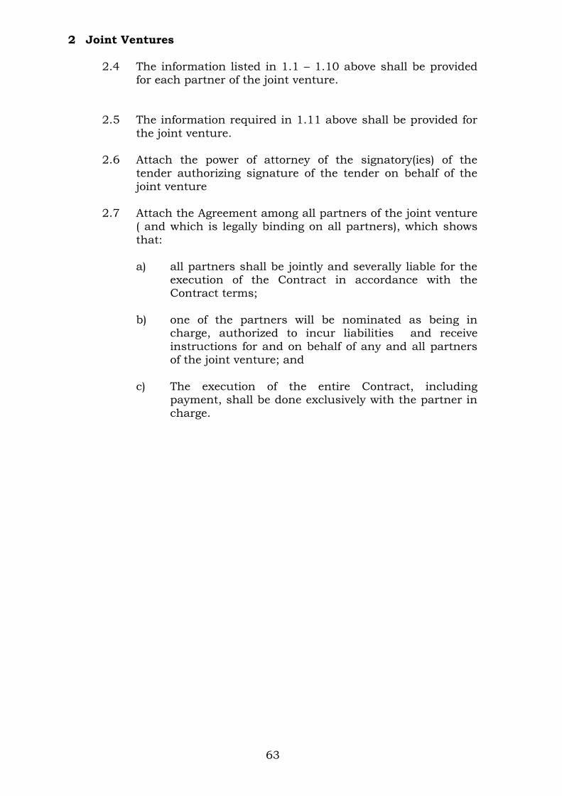
63
2 Joint Ventures
2.4 The information listed in 1.1 – 1.10 above shall be provided for each partner of the joint venture.
2.5 The information required in 1.11 above shall be provided for
the joint venture.
2.6 Attach the power of attorney of the signatory(ies) of the
tender authorizing signature of the tender on behalf of the joint venture
2.7 Attach the Agreement among all partners of the joint venture
( and which is legally binding on all partners), which shows
that:
a) all partners shall be jointly and severally liable for the execution of the Contract in accordance with the Contract terms;
b) one of the partners will be nominated as being in
charge, authorized to incur liabilities and receive
instructions for and on behalf of any and all partners of the joint venture; and
c) The execution of the entire Contract, including
payment, shall be done exclusively with the partner in
charge.
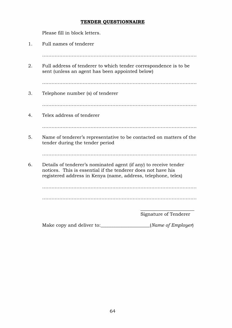
64
TENDER QUESTIONNAIRE
Please fill in block letters.
1. Full names of tenderer
……………………………………………………………………………………… 2. Full address of tenderer to which tender correspondence is to be
sent (unless an agent has been appointed below)
……………………………………………………………………………………… 3. Telephone number (s) of tenderer
………………………………………………………………………………………
4. Telex address of tenderer
……………………………………………………………………………………… 5. Name of tenderer’s representative to be contacted on matters of the
tender during the tender period
……………………………………………………………………………………… 6. Details of tenderer’s nominated agent (if any) to receive tender
notices. This is essential if the tenderer does not have his registered address in Kenya (name, address, telephone, telex)
………………………………………………………………………………………
……………………………………………………………………………………… _______________________
Signature of Tenderer
Make copy and deliver to:_____________________(Name of Employer)

65
CONFIDENTIAL BUSINESS QUESTIONNAIRE
You are requested to give the particulars indicated in Part 1 and either
Part 2 (a), 2 (b) or 2 (c) and 2 (d) whichever applies to your type of business.
You are advised that it is a serious offence to give false information on this Form.
Part 1 – General Business Name ……………………………………………………………………… Location of business premises; Country/Town……………………….
Plot No……………………………………… Street/Road …………………………
Postal Address……………………………… Tel No………………………………..
Nature of Business………………………………………………………………….. Current Trade Licence No…………………… Expiring date…………………
Maximum value of business which you can handle at any time: K.
pound……………………….. Name of your bankers………………………………………………………………
Branch…………………………………………………………………………………
Part 2 (a) – Sole Proprietor Your name in full…………………………………… Age………………………… Nationality………………………………… Country of Origin…………………
*Citizenship details …………………………………………………………………
Part 2 (b) – Partnership Give details of partners as follows: Name in full Nationality Citizenship Details Shares 1…………………………………………………………………………………… 2……………………………………………………………………………………
3…………………………………………………………………………………… Part 2(c) – Registered Company:
Private or public……………………………………………………………
State the nominal and issued capital of the Company-
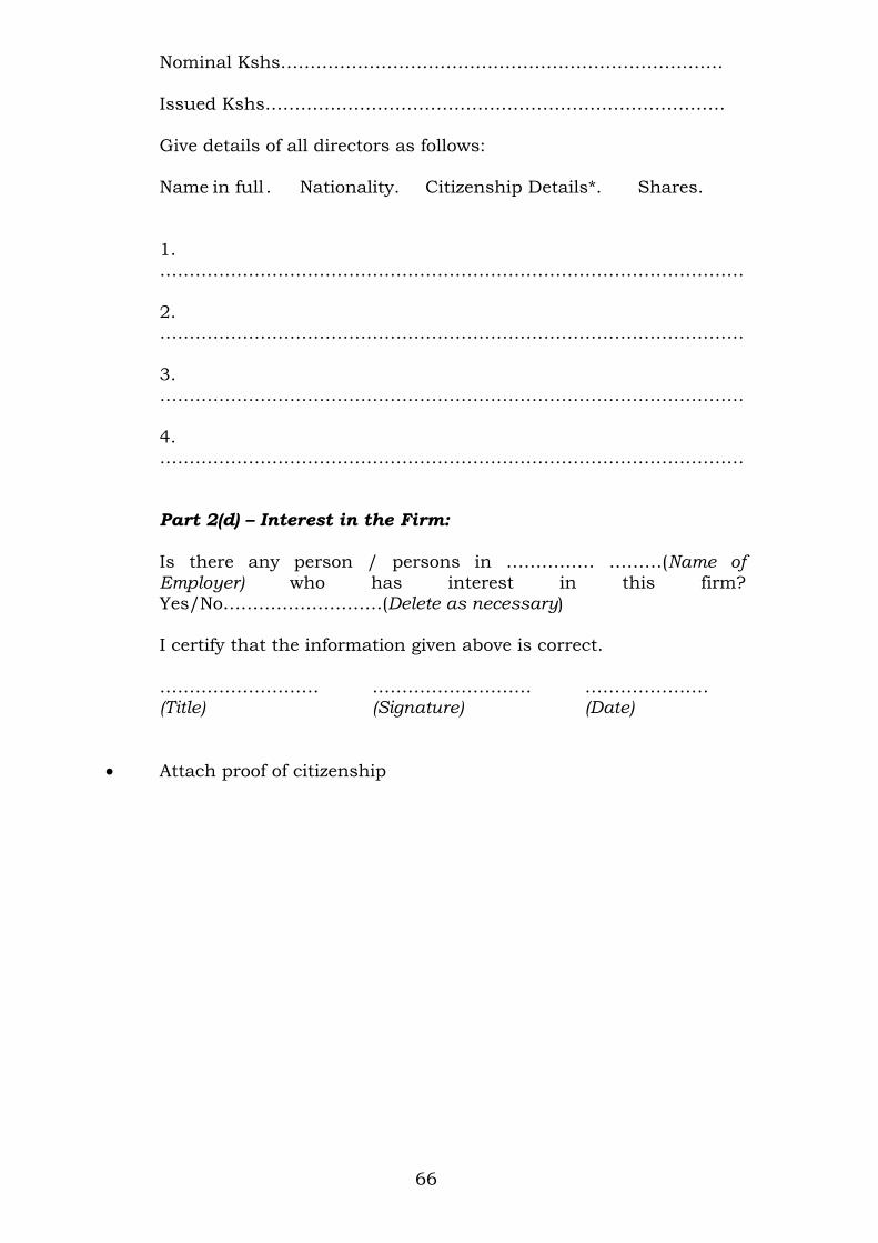
66
Nominal Kshs…………………………………………………………………
Issued Kshs……………………………………………………………………
Give details of all directors as follows: Name in full . Nationality. Citizenship Details*. Shares.
1.
………………………………………………………………………………………
2. ………………………………………………………………………………………
3. ………………………………………………………………………………………
4. ………………………………………………………………………………………
Part 2(d) – Interest in the Firm:
Is there any person / persons in …………… ………(Name of Employer) who has interest in this firm? Yes/No………………………(Delete as necessary)
I certify that the information given above is correct.
……………………… ……………………… ………………… (Title) (Signature) (Date)
Attach proof of citizenship

67
STATEMENT OF FOREIGN CURRENCY REQUIREMENTS
(See Clause 23] of the Conditions of Contract)
In the event of our Tender for the execution of____________________ __________________________(name of Contract) being accepted, we would require in accordance with Clause 21 of the Conditions of
Contract, which is attached hereto, the following percentage:
(Figures)………………………… (Words)………………………………… of the Contract Sum, (Less Fluctuations) to be paid in foreign
currency.
Currency in which foreign exchange element is required:
……………………………………………………………………………………… Date: The ………… Day of …………….. 20…………….
Enter 0% (zero percent) if no payment will be made in foreign
currency. Maximum foreign currency requirement shall be
_____________(percent) of the Contract Sum, less Fluctuations.
_____________________ (Signature of Tenderer)
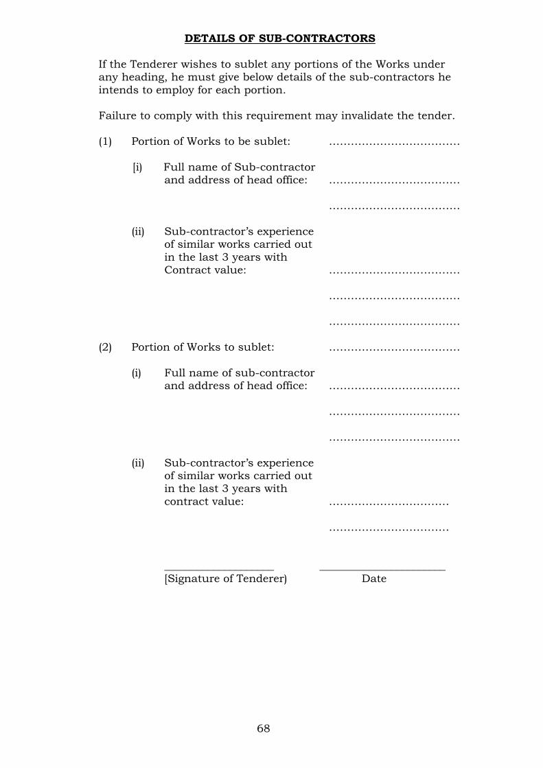
68
DETAILS OF SUB-CONTRACTORS
If the Tenderer wishes to sublet any portions of the Works under any heading, he must give below details of the sub-contractors he
intends to employ for each portion. Failure to comply with this requirement may invalidate the tender.
(1) Portion of Works to be sublet: ………………………………
[i) Full name of Sub-contractor and address of head office: ………………………………
………………………………
(ii) Sub-contractor’s experience of similar works carried out
in the last 3 years with Contract value: ………………………………
……………………………… ………………………………
(2) Portion of Works to sublet: ………………………………
(i) Full name of sub-contractor and address of head office: ………………………………
………………………………
………………………………
(ii) Sub-contractor’s experience of similar works carried out in the last 3 years with
contract value: ……………………………
……………………………
____________________ _______________________ [Signature of Tenderer) Date

69
LETTER OF NOTIFICATION OF AWARD
Address of Procuring Entity _____________________
_____________________ To:
RE: Tender No.
Tender Name This is to notify that the contract/s stated below under the above
mentioned tender have been awarded to you.
1. Please acknowledge receipt of this letter of notification signifying
your acceptance. 2. The contract/contracts shall be signed by the parties within 30
days of the date of this letter but not earlier than 14 days from the date of the letter.
3. You may contact the officer(s) whose particulars appear below on
the subject matter of this letter of notification of award. (FULL PARTICULARS)
SIGNED FOR ACCOUNTING OFFICER
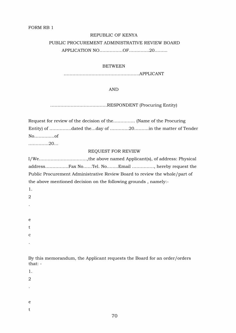
70
FORM RB 1
REPUBLIC OF KENYA
PUBLIC PROCUREMENT ADMINISTRATIVE REVIEW BOARD
APPLICATION NO…………….OF……….….20……...
BETWEEN
…………………………………………….APPLICANT
AND
…………………………………RESPONDENT (Procuring Entity)
Request for review of the decision of the…………… (Name of the Procuring
Entity) of ……………dated the…day of ………….20……….in the matter of Tender
No………..…of
…………..20…
REQUEST FOR REVIEW
I/We……………………………,the above named Applicant(s), of address: Physical
address…………….Fax No……Tel. No……..Email ……………, hereby request the
Public Procurement Administrative Review Board to review the whole/part of
the above mentioned decision on the following grounds , namely:-
1.
2
.
e
t
c
.
By this memorandum, the Applicant requests the Board for an order/orders
that: -
1.
2
.
e
t

71
c
SIGNED ……………….(Applicant)
Dated on…………….day of ……………/…20…
FOR OFFICIAL USE ONLY
Lodged with the Secretary Public Procurement Administrative Review Board on
………… day of ………....20….………
SIGNED
Board Secretary
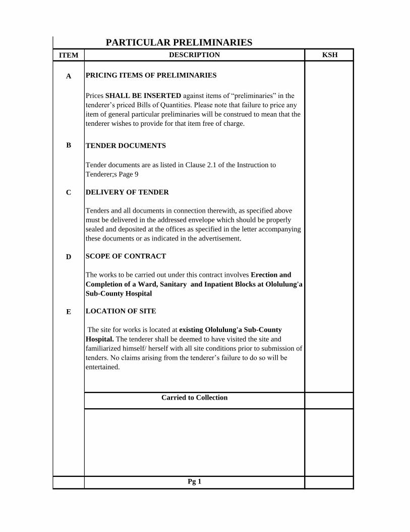
ITEM DESCRIPTION KSH
A PRICING ITEMS OF PRELIMINARIES
Prices SHALL BE INSERTED against items of “preliminaries” in the
tenderer’s priced Bills of Quantities. Please note that failure to price any
item of general particular preliminaries will be construed to mean that the
tenderer wishes to provide for that item free of charge.
B TENDER DOCUMENTS
Tender documents are as listed in Clause 2.1 of the Instruction to
Tenderer;s Page 9
C DELIVERY OF TENDER
Tenders and all documents in connection therewith, as specified above
must be delivered in the addressed envelope which should be properly
sealed and deposited at the offices as specified in the letter accompanying
these documents or as indicated in the advertisement.
D SCOPE OF CONTRACT
The works to be carried out under this contract involves Erection and
Completion of a Ward, Sanitary and Inpatient Blocks at Ololulung'a
Sub-County Hospital
E LOCATION OF SITE
The site for works is located at existing Ololulung'a Sub-County
Hospital. The tenderer shall be deemed to have visited the site and
familiarized himself/ herself with all site conditions prior to submission of
tenders. No claims arising from the tenderer’s failure to do so will be
entertained.
Carried to Collection
Pg 1
PARTICULAR PRELIMINARIES
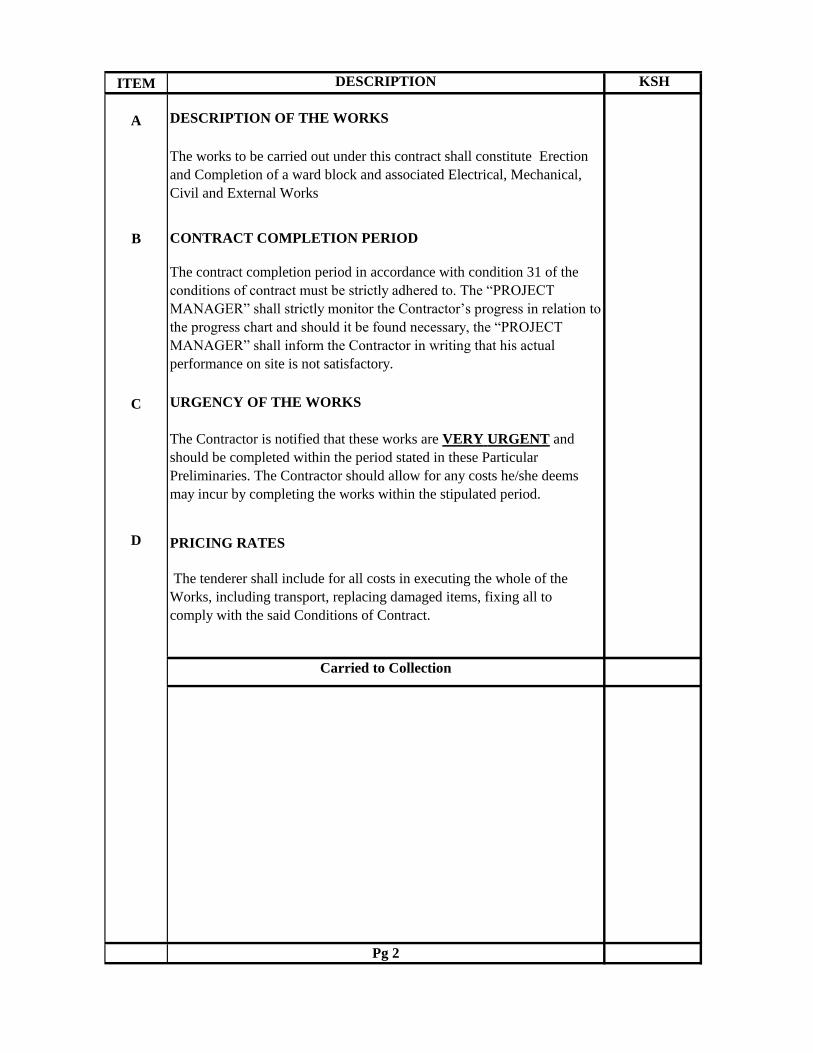
ITEM DESCRIPTION KSH
A DESCRIPTION OF THE WORKS
The works to be carried out under this contract shall constitute Erection
and Completion of a ward block and associated Electrical, Mechanical,
Civil and External Works
B CONTRACT COMPLETION PERIOD
The contract completion period in accordance with condition 31 of the
conditions of contract must be strictly adhered to. The “PROJECT
MANAGER” shall strictly monitor the Contractor’s progress in relation to
the progress chart and should it be found necessary, the “PROJECT
MANAGER” shall inform the Contractor in writing that his actual
performance on site is not satisfactory.
C URGENCY OF THE WORKS
The Contractor is notified that these works are VERY URGENT and
should be completed within the period stated in these Particular
Preliminaries. The Contractor should allow for any costs he/she deems
may incur by completing the works within the stipulated period.
D PRICING RATES
The tenderer shall include for all costs in executing the whole of the
Works, including transport, replacing damaged items, fixing all to
comply with the said Conditions of Contract.
Carried to Collection
Pg 2

ITEM DESCRIPTION KSH
AVALUE ADDED TAX; OTHER TAXES, DUTIES AND LEVIES
INFORCE
The contractor’s attention is drawn to the Legal Notice in the Finance Act
part 3 which Section 21(b) operative from 1st September, 1993 which
requires payment of VAT on all contracts. The tenderer is advised that in
accordance with Government Public notice No. 35 & 36 dated 11th
September 2003 operational from 1st October 2003, withholding VAT
will be levied against the contract sum by the Employer and remitted to
the Commissioner of VAT through all interim certificates. The contractor
should therefore include this tax in the in the rates and NOT at the
Grand Summary page .The contractor shall however include all other
taxes in the rates. No claim shall be entertained for failure to adhere to
this requirement.
B PAYMENTS
The tenderer’s attention is drawn to the fact that the GOVERNMENT
SHALL NOT MAKE ADVANCE PAYMENTS
C PAYMENT FOR MATERIALS ON SITE
All materials for incorporation in the works must be stored on site before
payment is effected, unless specifically exempted by the Project Manager.
This is to include materials of the Contractor, nominated sub-contractors
and nominated suppliers
D MATERIALS FROM DEMOLITIONS
Any materials arising from demolitions and not re-used shall become the
property of the government. The Contractor shall allow in his rates the
cost of transporting the demolished materials to the County Works
Office.
E MEASUREMENTS
In the event of any discrepancies arising between the Bills of Quantities
and the actual works, the site measurements shall generally take
precedence. However, such discrepancies between any contract
documents shall immediately be referred to the Project Manager.
Carried to Collection
Pg 3

ITEM DESCRIPTION KSH
A CLAIMS
It shall be a condition of this contract that upon it becoming reasonably
apparent to the Contractor that he has incurred losses and/or expenses due
any of the contract conditions, or by any other person whatsoever, he shall
present such claim or intent to claim notice to the PROJECT MANAGER
within the contract period. No claims shall be entertained upon the expiry
of the said .
B SIGNBOARD
Allow for providing erecting, maintaining throughout the course of the
Contract and afterwards clearing away a signboard as designed, specified
and approved by the Project Manager.
C LABOUR CAMPS
The Contractor shall NOT be allowed to house labour on site and is
therefore advised to allow for transporting workers to and from the site
during the tenure of the contract.
D WORKING CONDITIONS
The Contractor shall allow in his rates for any interference that he may
encounter in the course of execution of the works for the Client may in
some cases ask the Contractor not to proceed with the works until some
activities within the site are completed.
E TELEPHONE
The contractor shall provide a phone on site throughout the course of the
contract and make the necessary arrangements for connection to the public
telephone system and for paying all connection, rental and call charges in
connection therewith.
Carried to Collection
Pg 4

ITEM DESCRIPTION KSH
A EXISTING BUILDING SERVICES
Special precautions shall be required throughout the contract period to
avoid damage to the existing building, cables, drains and other services.
The Contractor shall allow for making good any damage arising from
his actions during execution of this contract at his own expense.
B PREVENTION OF ACCIDENT, DAMAGE OR LOSS
The contractor is notified that these works are to be carried out on a
restricted site where the client is going on with other normal activities.
The Contractor is instructed to take reasonable care in the execution of the
works as to prevent accidents, damage or loss and disruption of normal
activities being carried out by the Client. The Contractor shall allow in
his rates any expense be deems necessary by taking such care with the
site.
C SECURITY
The Contractor shall allow for providing adequate security for the works
and the workers in the course of execution of this contract. No claim will
be entertained from the Contractor for not maintaining adequate security
for both the works and workers
D EXISTING SERVICES
Priority shall be given to identifying the exsisting services before the
commencement of any work, the Contractor is to ascertain from the
relevant authority the exact position, depth and level of all existing
services in the area and he/she shall make whatever provisions may be
required by the authorities concerned for the support, maintenance and
protection of such services.
E BID SECURITY
The contractor shall provide a bid security duly signed, sealed and
stamped from an approved Institution in an approval format of required
amount
Carried to Collection
Pg 5
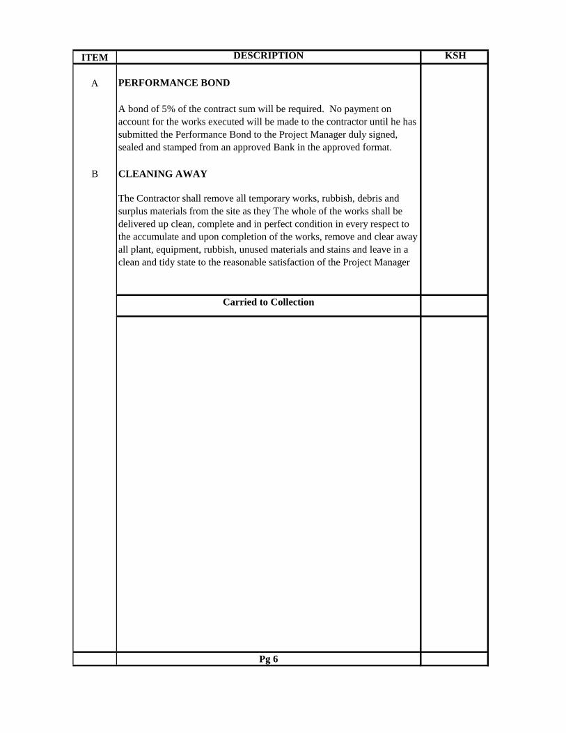
ITEM DESCRIPTION KSH
A PERFORMANCE BOND
A bond of 5% of the contract sum will be required. No payment on
account for the works executed will be made to the contractor until he has
submitted the Performance Bond to the Project Manager duly signed,
sealed and stamped from an approved Bank in the approved format.
B CLEANING AWAY
The Contractor shall remove all temporary works, rubbish, debris and
surplus materials from the site as they The whole of the works shall be
delivered up clean, complete and in perfect condition in every respect to
the accumulate and upon completion of the works, remove and clear away
all plant, equipment, rubbish, unused materials and stains and leave in a
clean and tidy state to the reasonable satisfaction of the Project Manager
Carried to Collection
Pg 6
ITEM DESCRIPTION KSH
COLLECTION
Brought forward from Pge 1
Brought forward from Pge 2
Brought forward from Pge 3
Brought forward from Pge 4
Brought forward from Pge5
Brought forward from Pge 6
Brought forward from Pge 7
PARTICULAR PRELIMINARY CARRIED TO GRAND
SUMMARY
Pg 8

ITEM DESCRIPTION Kshs.
PARTICULARS OF INSERTIONS TO BE MADE IN
APPENDIX TO CONTRACT AGREEMENT
The following are the insertions to be made in the appendix to
Defects Liability Period 6 months from Practical completion
Date of final measurement. 3 months from Practical completion
Date for Possession To be agreed with the Project Manager
Date of completion 32 weeks from the date of Possession
Liquidated and Ascertained Damages Ksh. 50,000 per week
Period of Interim Certificates Monthly
Period of Honouring Certificates 30 days
Percentage of Certified Value Retained 10%
Limit of Retention Fund 10%
Carried to Collection
Pg OH/PP/07
ITEM DESCRIPTION KSHS CTS
GENERAL PRELIMINARIES
A. PRICING OF ITEMS OF PRELIMINARIES AND PREAMBLES
Prices will be inserted against items of Preliminaries in the Contractor's priced Bills of
Quantities and Specification.
The Contractor shall be deemed to have included in his prices or rates for the various items in
the Bills of Quantities or Specification for all costs involved in complying with all the
requirements for the proper execution of the whole of the works in the Contract.
B. ABBREVIATIONS
Throughout these Bills, units of measurement and terms are abbreviated and shall be
interpreted as follows:-
C.M. Shall mean cubic metre
S.M. Shall mean square metre
L.M. Shall mean linear metre
MM Shall mean Millimetre
Kg. Shall mean Kilogramme
No. Shall mean Number
Prs. Shall mean Pairs
B.S Shall mean the British Standard Specification Published by theBritish Standards
Institution, 2 Park Street, London W.I., England.
Ditto Shall mean the whole of the preceding description except as qualified in the description
in which it occurs.
m.s. Shall mean measured separately.
a.b.d Shall mean as before described.
Carried to collection
Page 1 GEN PRELIMS

ITEM DESCRIPTION KSHS CTS
A. EXCEPTION TO THE STANDARD METHOD OF MEASUREMENT
Attendance ; Clause B19(a) of the Standard Method of Measurement is deleted and the
following clause is substituted:-
Attendance on nominated Sub-Contractors shall be given as an item in each case shall be
deemed to include: allowing use of standing scaffolding, mess rooms, sanitary accommodation
and welfare facilities; provision of special scaffolding where necessary;providing space for
office accommodation and for storage of plant and materials;providing light and water for
their work: clearing away rubbish; unloading checking and hoisting: providing electric power
and removing and replacing duct covers, pipe casings and the like necessary for the execution
and testing of Sub- Contractors' work and being responsible for the accuracy of the same.
Fix Only:-
"Fix Only" shall mean take delivery at nearest railway station (Unless otherwise stated), pay
all demurrage charges, load and transport to site where necessary, unload, store, unpack,
assemble as necessary, distribute to position, hoist and fix only.
B. EMPLOYER
The "Employer" is MERU COUNTY GOVERNMENT - MINISTRY OF HEALTH
The term "Employer" and "Meru County Government- Ministry of Health" wherever used
in the contract document shall be synonymous
C. PROJECT MANAGER
The term "P.M." wherever used in these Bills of Quantities shall be deemed to imply theProject Manager as defined in Condition 1 of the Conditions of Contract or such person or
persons as may be duly authorised to represent him on behalf of the Government.
D. ARCHITECT
The term "Architect" shall be deemed to mean "The Project Manager." as defined above
whose address unless otherwise notified is Ministry of Transport , Infrastructure Housing and
Urban Development (State Department of Public Works), P.O. Box 30743-00100,
NAIROBI.
E. QUANTITY SURVEYOR
The term "Quantity Surveyor" shall be deemed to mean "The Project Manager." as defined
above whose address unless otherwise notified is Ministry of Ministry of Transport ,
Infrastructure Housing and Urban Development (State Department of Public Works), P.O.
Box 30743-00100, NAIROBI.
F ELECTRICAL ENGINEER
The term "Electrical Engineer" shall be deemed to mean "The Project Manager." as defined
above whose address unless otherwise notified is Ministry of Land Housing and Urban
Development (State Department of Public Works), P.O. Box 30743-00100, NAIROBI.
G MECHANICAL ENGINEER
The term "Mechanical Engineer" shall be deemed to mean "The Project Manager." as defined
above whose address unless otherwise notified is Ministry of Land Housing and Urban
Development (State Department of Public Works), P.O. Box 30743-00100, NAIROBI.
Carried to collection
Page 2 GEN PRELIMS
ITEM DESCRIPTION KSHS CTS
A STRUCTURAL ENGINEER
The term "Structural Engineer" shall be deemed to mean "The Project Manager." as defined
above whose address unless otherwise notified is Ministry of Ministry of Transport ,
Infrastructure, Housing and Urban Development (State Department of Public Works), P.O.
Box 30743-00100, NAIROBI.
B FORM OF CONTRACT
The Form of Contract shall be as stipulated in the Republic of Kenya's Standard Tender
Document for Procurement of Building Works(2006 Edition) included herein The Conditions
of Contract are also included herein Conditions of Contract These are numbered from 1 to
37 as set out in pages 20 to 40 of these tender documents.Particulars of insertions to be made
in the Appendix to the Contract Agreement will be found in the Particular Preliminaries part
of these Bills of Quantities
C PLANT, TOOLS AND VEHICLES
Allow for providing all scaffolding, plant, tools and vehicles required for the worksexcept in
so far as may be stated otherwise herein and except for such items specifically and only
required for the use of nominated Sub-Contractors as described herein. No timber used for
scaffolding, formwork or temporary works of any kind shall be used afterwards in the
permanent work.
D MATERIALS AND WORKMANSHIP.
All materials and workmanship used in the execution of the work shall be of the best quality
and description unless otherwise stated. The Contractor shall order all materials to be obtained
from overseas immediately after the Contract is signed and shall also order materials to be
obtained from local sourses as early as necessary to ensure that they are on site when required
for use in the works when required. The Bills of Quantities shall not be used for the purposed
of ordering materials
E SIGN FOR MATERIALS SUPPLIED.
The Contractor will be required to sign a receipt for all articles and materials supplied by the
PROJECT MANAGER at the time of taking deliver thereof, as having received them in good
order and condition, and will thereafter be responsible for any loss or damage and for
replacements of any such loss or damage with articles and/or materials which will be supplied
by the PROJECT MANAGER at the current market prices including Customs Duty and
V.A.T., all at the Contractor's own cost and expense, to the satisfaction of the PROJECT
F STORAGE OF MATERIALS
The Contractor shall provide at his own risk and cost where directed on the site weather proof
lock-up sheds and make good damaged or disturbed surfaces upon completion to the
satisfaction of the PROJECT MANAGER Nominated Sub-Contractors are to be made liable
for the cost of any storage accommodation provided especially for their use.
Carried to collection
Page 3 GEN PRELIMS
ITEM DESCRIPTION KSHS CTS
A SAMPLES
The Contractor shall furnish at his own cost any samples of materials or workmanship
including concrete test cubes required for the works that may be called for by the PROJECT
MANAGER for his approval until such samples are approved by the PROJECT MANAGER
and the PROJECT MANAGER, may reject any materials or workmanship not in his opinion
to be up to approved samples. The PROJECT MANAGER shall arrange for the testing of such
materials as he may at his discretion deem desirable, but the testing shall be made at the
expense of the Contractor and not at the expense of the PROJECT MANAGER. The
Contractor shall pay for the testing in accordance with the current scale of testing charges laid
down by the Ministry of Public Works.The procedure for submitting samples of materials for testing and the method of marking for
identification shall be as laid down by the PROJECT MANAGER The Contractor shall allow
in his tender for such samples and tests except those in connection with nominated sub-
contractors' work.
B GOVERNMENT ACTS REGARDING WORK PEOPLE ETC.
Allow for complying with all Government Acts, Orders and Regulations in connection with
the employment of Labour and other matters related to the execution of the works. In
particular the Contractor's attention is drawn to the provisions of the Factory Act 1950 and his
tender must include for all costs arising or resulting from compliance with any Act, Order or
Regulation relating to Insurances, pensions and holidays for workpeople or so the safety,
health and welfare of the workpeople. The Contractor must make himself fully acquainted with
current Acts and Regulations,including Police Regulations regarding the movement, housing,
security and control of labour, labour camps , passes for transport, etc. It is most important
that the Contractor, before tendering, shall obtain from the relevant Authority the fullest
information regarding all such regulations and/or restrictions which may affect the information
regarding all such regulations and/or restrictions which may affect the organisation of the
works, supply and control of labour, etc., and allow accordingly in his tender.
No claim in respect of want of knowledge in this connection will be entertained.
C SECURITY OF WORKS ETC.
The Contractor shall be entirely responsible for the security of all the works stores,materials,
plant, personnel, etc., both his own and sub-contractors' and must provide all necessary
watching, lighting and other precautions as necessary to ensure security against theft, loss or
damage and the protection of the public.
B PUBLIC AND PRIVATE ROADS.
Maintain as required throughout the execution of the works and make good any damage to
public or private roads arising from or consequent upon the execution of the works to the
satisfaction of the local and other competent authority and the PROJECT MANAGER
D VISIT SITE AND EXAMINE DRAWINGS.
The Contractor is recommended to examine the drawings and visit the site the location of
which is described in the Particular Preliminaries hereof. He shall be deemed to have
acquainted himself therewith as to its nature, position, means of access or any other matter
which, may affect his tender. No claim arising from his failure to comply with this
recommendation will be considered.
Carried to collection
Page 4 GEN PRELIMS

ITEM DESCRIPTION KSHS CTS
A ACCESS TO SITE AND TEMPORARY ROADS.
Means of access to the Site shall be agreed with the PROJECT MANAGER prior to
commencement of the work and Contractor must allow for building any necessary temporary
access roads for the transport of the materials, plant and workmen as may be required for the
complete execution of the works including the provision of temporary culverts, crossings,
bridges, or any other means of gaining access to the Site. Upon completion of the works, the
Contractor shall remove such temporary access roads; temporary culverts, bridges, etc., and
make good and reinstate all works and surfaces disturbed to the satisfaction of the PROJECT
MANAGER
B AREA TO BE OCCUPIED BY THE CONTRACTOR
The area of the site which may be occupied by the Contractor for use of storage and for the
purpose of erecting workshops, etc., shall be defined on site by the PROJECT MANAGER
C OFFICE ETC. FOR THE PROJECT MANAGER
The Contractor shall provide, erect and maintain where directed on site and afterwards
dismantle the site office of the type noted in the Particular Preliminaries, complete with
Furniture. He shall also provide a strong metal trunk complete with strong hasp and staple
fastening and two keys. He shall provide, erect and maintain a lock-up type water or bucket
closet for the sole use of the PROJECT MANAGER including making temporary connections
to the drain where applicable to the satisfaction of Government and Medical Officer of Health
and shall provide services of cleaner and pay all conservancy charges and keep both office and
closet in a clean and sanitary condition from commencement to the completion of the works
and dismantle and make good disturbed surfaces. The office and closet shall be completed
before the Contractor is permitted to commence the works. The Contractor shall make
available on the Site as and when required by the "PROJECT MANAGER" a modern and
accurate level together with levelling staff, ranging rods and 50 metre metallic or linen tape.
D WATER AND ELECTRICITY SUPPLY FOR THE WORKS
The Contractor shall provide at his own risk and cost all necessary water, electric light and
power required for use in the works. The Contractor must make his own arrangements for
connection to the nearest suitable water main and for metering the water used. He must also
provide temporary tanks and meters as required at his own cost and clear away when no longer
required and make good on completion to the entire satisfaction of the PROJECT MANAGER
. The Contractor shall pay all charges in connection herewith. No guarantee is given or
implied that sufficient water will be available from mains and the Contractor must make his
own arrangements for augmenting this supply at his own cost. Nominated Sub--contractors are
to be made liable for the cost of any water or electric current used and for any installation
provided especially for their own use.
E SANITATION OF THE WORKS
The Sanitation of the works shall be arranged and maintained by the Contractor to the
satisfaction of the Government and/or Local Authorities, Labour Department and the
PROJECT MANAGER
Carried to collection
A SUPERVISION AND WORKING HOURS
Page 5 GEN PRELIMS
ITEM DESCRIPTION KSHS CTS
The works shall be executed under the direction and to the entire satisfaction in all respects of
the PROJECT MANAGER who shall at all times during normal working hours have access to
the works and to the yards and workshops of the Contractor and sub-Contractors or other
places where work is being prepared for the contract.
B PROVISIONAL SUMS.
The term "Provisional Sum" wherever used in these Bills of Quantities shall have the meaning
stated in Section A item A7(i) of the Standard Method of Measurement.Such sums are net and
no addition shall be made to them for profit.
C PRIME COST (OR P.C.) SUMS.
The term "Prime Cost Sum" or "P.C. Sum" wherever used in these Bills of Quantities shall
have the meaning stated in Section A item A7 (ii) of the Standard Method of Measurement .
Persons or firms nominated by the PROJECT MANAGER to execute work or to provide and
fix materials or goods are described herein as Nominated Sub-Contractors.Persons or firms so
nominated to supply goods or materials are described herein as Nominated Suppliers.
D PROGRESS CHART.
The Contractor shall provide within two weeks of Possession of Site and in agreement with the
PROJECT MANAGER a Progress Chart for the whole of the works including the works of
Nominated Sub-Contractors ; one copy to be handed to the PROJECT MANAGER and a
further copy to be retained on Site. Progress to be recorded and chart to be amended as
necessary as the work proceeds.
E ADJUSTMENT OF P.C. SUMS.
In the final account all P.C. Sums shall be deducted and the amount properly expended upon
the PROJECT MANAGER'S order in respect of each of them added to the Contract sum. The
Contractor shall produce to the PROJECT MANAGER such quotations, invoices or bills,
properly receipted, as may be necessary to show the actual details of the sums paid by the
Contractor. Items of profit upon P.C. Sums shall be adjusted in the final account pro-rata to
the amount paid. Items of "attendance" (as previously described) following P.C. Sums shall be
adjusted pro-rata to the physical extent of the work executed (not pro-rata to the amount paid)
and this shall apply even though the Contractor's priced Bill shows a percentage in the rate
column in respect of them. Should the Contractor be permitted to tender and his tender be
accepted of any work for which a P.C. Sum is included in these Bill of Quantities profit and
attendance will be allowed at the same rate as it would be if the work were executed by a
Nominated Sub-Contractor.F ADJUSTMENT OF PROVISIONAL SUMS.
In the final account all Provisional Sums shall be deducted and the value of the work properly
executed in respect of them upon the PROJECT MANAGER's order added to the Contract
Sum. Such work shall be valued , but should any part of the work be executed by a Nominated
Sub-Contractor, the value of such work or articles for the work to be supplied by a Nominated
Supplier, the value of such work or articles shall be treated as a P.C. Sum and profit and
attendance comparable to that contained in the priced Bills of Quantities for similar items
Carried to collection
A NOMINATED SUB-CONTRACTORS
Page 6 GEN PRELIMS
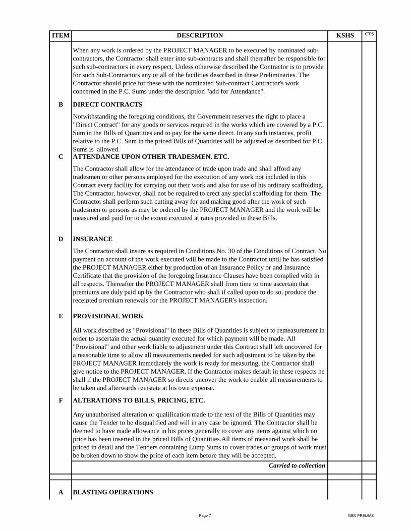
ITEM DESCRIPTION KSHS CTS
When any work is ordered by the PROJECT MANAGER to be executed by nominated sub-
contractors, the Contractor shall enter into sub-contracts and shall thereafter be responsible for
such sub-contractors in every respect. Unless otherwise described the Contractor is to provide
for such Sub-Contractors any or all of the facilities described in these Preliminaries. The
Contractor should price for these with the nominated Sub-contract Contractor's work
concerned in the P.C. Sums under the description "add for Attendance".
B DIRECT CONTRACTS
Notwithstanding the foregoing conditions, the Government reserves the right to place a
"Direct Contract" for any goods or services required in the works which are covered by a P.C.
Sum in the Bills of Quantities and to pay for the same direct. In any such instances, profit
relative to the P.C. Sum in the priced Bills of Quantities will be adjusted as described for P.C.
Sums is allowed.C ATTENDANCE UPON OTHER TRADESMEN, ETC.
The Contractor shall allow for the attendance of trade upon trade and shall afford any
tradesmen or other persons employed for the execution of any work not included in this
Contract every facility for carrying out their work and also for use of his ordinary scaffolding.
The Contractor, however, shall not be required to erect any special scaffolding for them. The
Contractor shall perform such cutting away for and making good after the work of such
tradesmen or persons as may be ordered by the PROJECT MANAGER and the work will be
measured and paid for to the extent executed at rates provided in these Bills.
D INSURANCE
The Contractor shall insure as required in Conditions No. 30 of the Conditions of Contract. No
payment on account of the work executed will be made to the Contractor until he has satisfied
the PROJECT MANAGER either by production of an Insurance Policy or and Insurance
Certificate that the provision of the foregoing Insurance Clauses have been complied with in
all respects. Thereafter the PROJECT MANAGER shall from time to time ascertain that
premiums are duly paid up by the Contractor who shall if called upon to do so, produce the
receipted premium renewals for the PROJECT MANAGER's inspection.
E PROVISIONAL WORK
All work described as "Provisional" in these Bills of Quantities is subject to remeasurement in
order to ascertain the actual quantity executed for which payment will be made. All
"Provisional" and other work liable to adjustment under this Contract shall left uncovered for
a reasonable time to allow all measurements needed for such adjustment to be taken by the
PROJECT MANAGER Immediately the work is ready for measuring, the Contractor shall
give notice to the PROJECT MANAGER. If the Contractor makes default in these respects he
shall if the PROJECT MANAGER so directs uncover the work to enable all measurements to
be taken and afterwards reinstate at his own expense.
F ALTERATIONS TO BILLS, PRICING, ETC.
Any unauthorised alteration or qualification made to the text of the Bills of Quantities may
cause the Tender to be disqualified and will in any case be ignored. The Contractor shall be
deemed to have made allowance in his prices generally to cover any items against which no
price has been inserted in the priced Bills of Quantities.All items of measured work shall be
priced in detail and the Tenders containing Lump Sums to cover trades or groups of work must
be broken down to show the price of each item before they will be accepted.
Carried to collection
A BLASTING OPERATIONS
Page 7 GEN PRELIMS
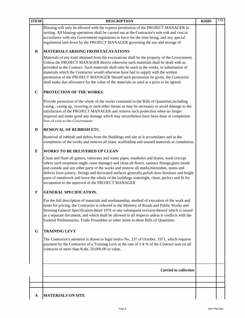
ITEM DESCRIPTION KSHS CTS
Blasting will only be allowed with the express permission of the PROJECT MANAGER in
writing. All blasting operations shall be carried out at the Contractor's sole risk and cost in
accordance with any Government regulations in force for the time being, and any special
regulations laid down by the PROJECT MANAGER governing the use and storage of
explosives.B MATERIALS ARISING FROM EXCAVATIONS
Materials of any kind obtained from the excavations shall be the property of the Government.
Unless the PROJECT MANAGER directs otherwise such materials shall be dealt with as
provided in the Contract. Such materials shall only be used in the works, in substitution of
materials which the Contractor would otherwise have had to supply with the written
permission of the PROJECT MANAGER Should such permission be given, the Contractor
shall make due allowance for the value of the materials so used at a price to be agreed.
C PROTECTION OF THE WORKS.
Provide protection of the whole of the works contained in the Bills of Quantities,including
casing , casing up, covering or such other means as may be necessary to avoid damage to the
satisfaction of the PROJECT MANAGER and remove such protection when no longer
required and make good any damage which may nevertheless have been done at completion
free of cost to the Government.
D REMOVAL OF RUBBISH ETC.
Removal of rubbish and debris from the Buildings and site as it accumulates and at the
completion of the works and remove all plant, scaffolding and unused materials at completion.
E WORKS TO BE DELIVERED UP CLEAN
Clean and flush all gutters, rainwater and waste pipes, manholes and drains, wash (except
where such treatment might cause damage) and clean all floors, sanitary fittings,glass inside
and outside and any other parts of the works and remove all marks,blemishes, stains and
defects from joinery, fittings and decorated surfaces generally,polish door furniture and bright
parts of metalwork and leave the whole of the buildings watertight, clean, perfect and fit for
occupation to the approval of the PROJECT MANAGER
F GENERAL SPECIFICATION.
For the full description of materials and workmanship, method of execution of the work and
notes for pricing, the Contractor is referred to the Ministry of Roads and Public Works and
Housing General Specification dated 1976 or any subsequent revision thereof which is issued
as a separate document, and which shall be allowed in all respects unless it conflicts with the
General Preliminaries, Trade Preambles or other items in these Bills of Quantities.
G TRAINING LEVY
The Contractor's attention is drawn to legal notice No. 237 of October, 1971, which requires
payment by the Contractor of a Training Levy at the rate of 1/4 % of the Contract sum on all
contracts of more than Kshs. 50,000.00 in value.
Carried to collection
A MATERIALS ON SITE
Page 8 GEN PRELIMS

ITEM DESCRIPTION KSHS CTS
All materials for incorporation in the works must be stored on or adjacent to the site before
payment is effected unless specifically exempted by the PROJECT MANAGER. This includes
the materials of the Main Contractor, Nominated Sub-Contractors and Nominated Suppliers.
B HOARDING
The Contractor shall enclose the site or part of the works under construction with a hoarding
2400 mm high consisting of iron sheets on 100 x 50 mm timber posts firmly secured at 1800
mm centres with two 75 x 50 mm timber rails approximately three hundred and fifty metres.
The Contractor is in addition required to take all precautions necessary for the safe custody of
the works,materials, plant, public and Employer's property on the site.
C CONTRACTOR'S SUPERINTENDENCE/SITE AGENT
The Contractor shall constantly keep on the works a literate English speaking Agent or
Representative, competent and experienced in the kind of work involved who shall give his
whole experience in the kind of work involved and shall give his whole time to the
superintendence of the works. Such Agent or Representative shall receive on behalf of the
Contractor all directions and instructions from the Project Manager and such directions shall
be deemed to have been given to the Contractor in accordance with the Conditions of
Contract.
Carried to collection
COLLECTION
Brought Forward From Page GP/1
Brought Forward From Page GP/2
Brought Forward From Page GP/3
Brought Forward From Page GP/4
Brought Forward From Page GP/5
Brought Forward From Page GP/6
Brought Forward From Page GP/7
Brought Forward From Page GP/8
Brought Forward From Above
TOTAL FOR GENERAL PRELIMINARIES
CARRIED TO GRAND SUMMARY
Page 9 GEN PRELIMS
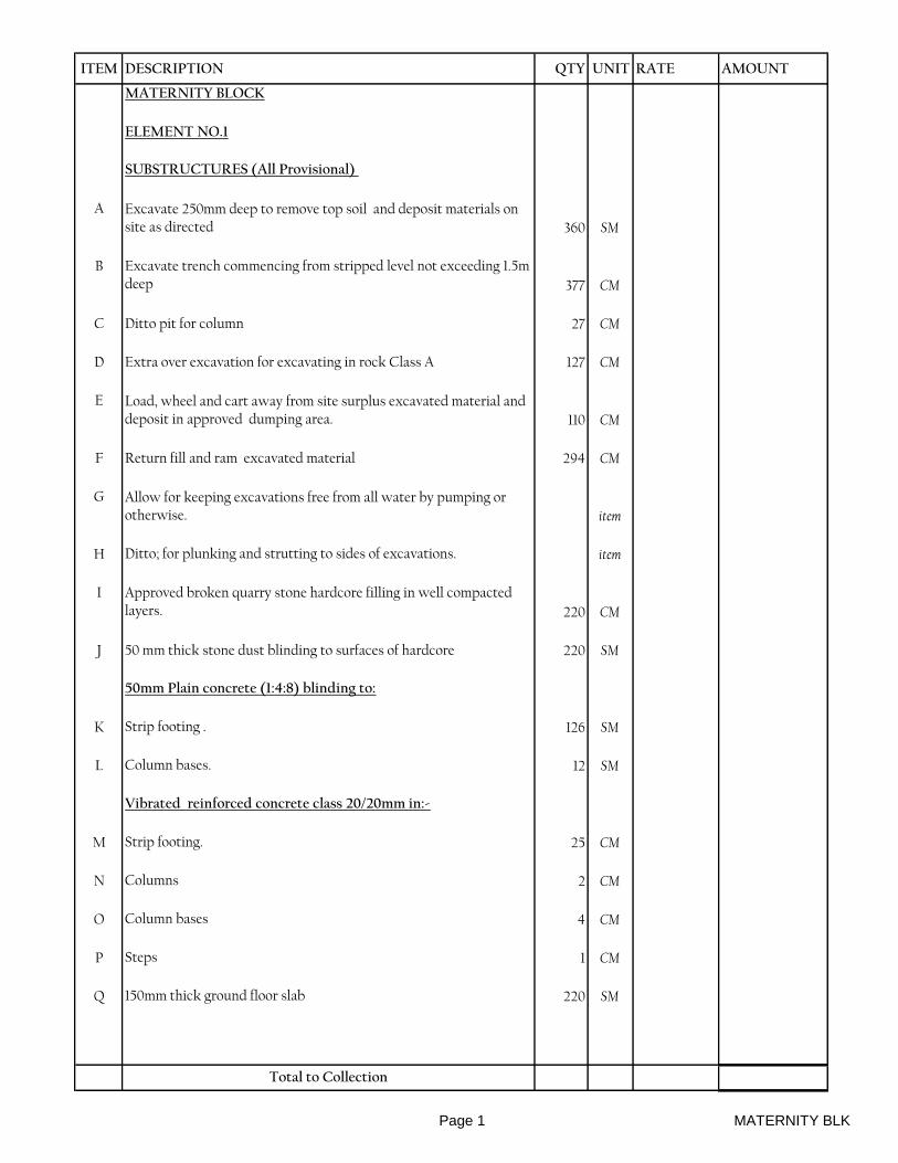
ITEM DESCRIPTION QTY UNIT RATE AMOUNT
MATERNITY BLOCK
ELEMENT NO.1
SUBSTRUCTURES (All Provisional)
A Excavate 250mm deep to remove top soil and deposit materials on site as directed 360 SM
B Excavate trench commencing from stripped level not exceeding 1.5m deep 377 CM
C Ditto pit for column 27 CM
D Extra over excavation for excavating in rock Class A 127 CM
E Load, wheel and cart away from site surplus excavated material and deposit in approved dumping area. 110 CM
F Return fill and ram excavated material 294 CM
G Allow for keeping excavations free from all water by pumping or otherwise. item
H Ditto; for plunking and strutting to sides of excavations. item
I Approved broken quarry stone hardcore filling in well compacted layers. 220 CM
J 50 mm thick stone dust blinding to surfaces of hardcore 220 SM
50mm Plain concrete (1:4:8) blinding to:
K Strip footing . 126 SM
L Column bases. 12 SM
Vibrated reinforced concrete class 20/20mm in:-
M Strip footing. 25 CM
N Columns 2 CM
O Column bases 4 CM
P Steps 1 CM
Q 150mm thick ground floor slab 220 SM
Total to Collection
Page 1 MATERNITY BLK
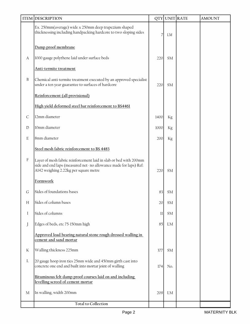
ITEM DESCRIPTION QTY UNIT RATE AMOUNT
Ex. 250mm(average) wide x 250mm deep trapezium shaped thicknessing including handpacking hardcore to two sloping sides
7 LM
Damp proof membrane
A 1000 gauge polythene laid under surface beds 220 SM
Anti-termite treatment
B Chemical anti-termite treatment executed by an approved specialist under a ten year guarantee to surfaces of hardcore 220 SM
Reinforcement (all provisional)
High yield deformed steel bar reinforcement to BS4461
C 12mm diameter 1400 Kg
D 10mm diameter 1000 Kg
E 8mm diameter 200 Kg
Steel mesh fabric reinforcement to BS 4483
F Layer of mesh fabric reinforcement laid in slab or bed with 200mm side and end laps (measured net- no allowance made for laps) Ref: A142 weighing 2.22kg per square metre 220 SM
Formwork
G Sides of foundations bases 83 SM
H Sides of column bases 20 SM
I Sides of columns 11 SM
J Edges of beds, etc 75-150mm high 85 LM
Approved load bearing natural stone rough dressed walling in cement and sand mortar
K Walling thickness 225mm 377 SM
L 20 gauge hoop iron ties 25mm wide and 450mm girth cast into concrete one end and built into mortar joint of walling 174 No.
Bituminous felt damp proof courses laid on and including levelling screed of cement mortar
M In walling, width 200mm 209 LM
Total to Collection
Page 2 MATERNITY BLK

ITEM DESCRIPTION QTY UNIT RATE AMOUNT
Plinth finishes
Cement and sand (1:4) rendering
A Rendering to concrete surfaces finished with a steel float, thickness 20mm 55 SM
Prepare and apply three coats bituminous paint
B Rendered surfaces externally 55 SM
Paving
C 100mm thick murrum blinding to hardcore;
well compacted 67 SM
D Treat surfaces of blinded hardcore with
approved weed killer 67 SM
Precast concrete paving slab; laid square in cement and sand mortar (1:4)
E 600 x 600 x 50mm thick 67 SM
F Labour and materials for raking cutting 3 LM
Total to Collection
Collection
Brought forward from page 01
Brought forward from page 02
Above
Total of Element 01 Carried to Summary
Page 3 MATERNITY BLK

ITEM DESCRIPTION QTY UNIT RATE AMOUNT
ELEMENT NO. 2
R.C. SUPERSTRUCTURE
Vibrated reinforced concrete class 20
A Beams 16 CM
B Columns 3 CM
Reinforcement
High yield deformed steel bar reinforcement to BS 4461
C 16mm diameter 200 Kg
D 12mm diameter 1000 Kg
E 8mm diameter 800 Kg
Formwork
F Sides of columns 30 SM
G Sides and soffits of beams 275 SM
Total of Element 02 Carried to Summary
Page 4 MATERNITY BLK

ITEM DESCRIPTION QTY UNIT RATE AMOUNT
ELEMENT NO. 3
SUPERSTRUCTURE WALLING
EXTERNAL
Approved load bearing fine chiselled dressed and rubbed stone walling in cement and sand mortar
A Walling, thickness 200mm 167 SM
INTERNAL
Approved load bearing machine dressed stone walling in cement and sand mortor
B Walling, thickness 200mm 154 SM
C Walling, thickness 150mm 28 SM
D Walling, thickness 100mm 25 SM
Total of Element 03 Carried to Summary
Page 5 MATERNITY BLK
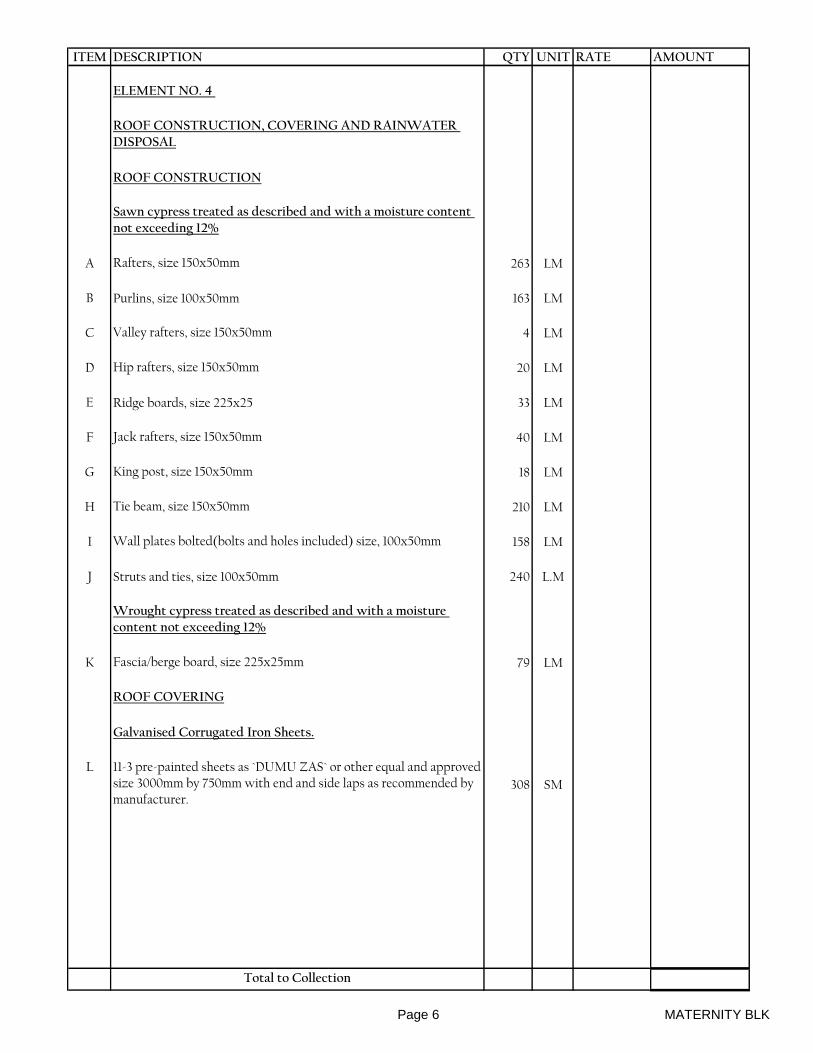
ITEM DESCRIPTION QTY UNIT RATE AMOUNT
ELEMENT NO. 4
ROOF CONSTRUCTION, COVERING AND RAINWATER DISPOSAL
ROOF CONSTRUCTION
Sawn cypress treated as described and with a moisture content not exceeding 12%
A Rafters, size 150x50mm 263 LM
B Purlins, size 100x50mm 163 LM
C Valley rafters, size 150x50mm 4 LM
D Hip rafters, size 150x50mm 20 LM
E Ridge boards, size 225x25 33 LM
F Jack rafters, size 150x50mm 40 LM
G King post, size 150x50mm 18 LM
H Tie beam, size 150x50mm 210 LM
I Wall plates bolted(bolts and holes included) size, 100x50mm 158 LM
J Struts and ties, size 100x50mm 240 L.M
Wrought cypress treated as described and with a moisture content not exceeding 12%
K Fascia/berge board, size 225x25mm 79 LM
ROOF COVERING
Galvanised Corrugated Iron Sheets.
L 11-3 pre-painted sheets as `DUMU ZAS` or other equal and approved size 3000mm by 750mm with end and side laps as recommended by manufacturer.
308 SM
Total to Collection
Page 6 MATERNITY BLK
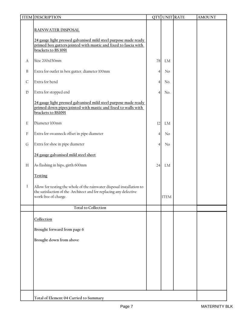
ITEM DESCRIPTION QTY UNIT RATE AMOUNT
RAINWATER DISPOSAL
24 gauge light pressed galvanised mild steel purpose made ready primed box gutters jointed with mastic and fixed to fascia with brackets to BS 1091
A Size 200x150mm 78 LM
B Extra for outlet in box gutter, diameter 100mm 4 No
C Extra for bend 4 No.
D Extra for stopped end 4 No.
24 gauge light pressed galvanised mild steel purpose made ready primed down pipes jointed with mastic and fixed to walls with brackets to BS1091
E Diameter 100mm 12 LM
F Extra for swanneck offset in pipe diameter 4 No
G Extra for shoe in pipe diameter 4 No
24 gauge galvanised mild steel sheet
H As flashing in hips, girth 600mm 24 LM
Testing
I Allow for testing the whole of the rainwater disposal installation to the satisfaction of the Architect and for replacing any defective work free of charge. ITEM
Total to Collection
Collection
Brought forward from page 6
Brought down from above
Total of Element 04 Carried to Summary
Page 7 MATERNITY BLK

ITEM DESCRIPTION QTY UNIT RATE AMOUNT
ELEMENT NO. 5:
WINDOWS
Precast concrete trimming finished fair on all exposed faces
A Cills, size 300x75mm 27 LM
B Mesh reinforcement to BS4483 in precast units 5 SM
Pelmet boxes in Wrought mahogany
C Window boards with one labour plugged, size 125x25mm. 27 LM
D Pelmet fascia, size 150x25mm 31 LM
E Pelmet top, size 125x25mm 31 LM
F Boxed end of pelmet, size 150x125x25mm 50 No.
G Bearer plugged, size 50x50mm 31 LM
H Quadrant plugged, diameter 15mm 31 LM
Curtain tracks
I Brass "H" section curtain track with gliders (one per 100mm of track), end stops and brackets screwed at 600mm centers 26 LM
Purpose made small panel mild steel ready primed casement window to schedule with pressed steel ventilating hood and 16mm square bar burglar proofing in openings and polished brass window ironmongery as supplied by Kensmetal Industries Ltd. and fixed to
J Window overall size,1200 x 1500mm 20 No.
K Window overall size, 900 x 1000mm 5 No.
L Mild steel grill comprising 16mm diameter square twisted horizontal and vertical bars at 100mm centres and including fixing to R.C walling (m.s) Overall size 1200 x 1500mm high 20 NO
M Ditto, Overall size 900 x 1000mm high 5 NO
Clear sheet glass
N 4mm glass and glazing to metal with putty in panes not exceeding 0.1 square meter 36 SM
Obscure sheet glass
P 4mm glass and glazing to metal with putty in panes not exceeding 0.1 square meter 5 SM
Total of Element 05 Carried to Summary
Page 8 MATERNITY BLK

ITEM DESCRIPTION QTY UNIT RATE AMOUNT
ELEMENT NO. 6:
DOORS
EXTERNAL
Standard steel casement door
A Metal casement steel single leaf door in 50x45mm RHS bottom, middle and top rails, 50x45mm RHS stiles infilled with steel panels welded to door all framed to detail overall size 1800x2100mm high,double leaf. 2 No.
B Louvred dead light,50×45mm framing with 150mm wide steel louvres 4 no.Overall size 1800×600mm. 2 No.
INTERNAL
Flush doors
C 45 mm solid core flush door faced both sides with 3mm plywood veneered and hardwood lipped all round, size 800 x 2100mm.Including fanlight 800×600mm. 6 No.
D Ditto,900×2100,double leaf.Fanlight 900×600mm. 4 No.
E Ditto,1500×2100,double leaf.Fanlight 1500×600mm. 10 No.
Door frames and finishing in wrought cypress.
F Frame to detail size, 150x50mm 119 LM
G Ditto,mullion with 2no. Labour. 18 LM
H Architrave to detail size, 45x25mm 119 LM
I Quadrant bead, diameter 15mm 119 LM
J Beading to detail size, 10x10mm 98 L.M
Clear sheet glass
K 4mm glass and glazing to wood with beads (measured separately) in panes exceeding 0.1 but not exceeding 0.5 square meters 8 SM
Sundries
L 10mm galvanised mild steel dowel 100mm long let into foot of frame and grouted into mortice in floor 120 No.
Total to Collection
Page 9 MATERNITY BLK
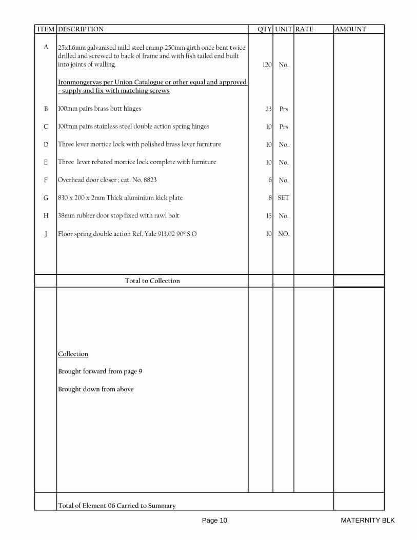
ITEM DESCRIPTION QTY UNIT RATE AMOUNT
A 25x1.6mm galvanised mild steel cramp 250mm girth once bent twice drilled and screwed to back of frame and with fish tailed end built into joints of walling. 120 No.
Ironmongeryas per Union Catalogue or other equal and approved - supply and fix with matching screws
B 100mm pairs brass butt hinges 23 Prs
C 100mm pairs stainless steel double action spring hinges 10 Prs
D Three lever mortice lock with polished brass lever furniture 10 No.
E Three lever rebated mortice lock complete with furniture 10 No.
F Overhead door closer ; cat. No. 8823 6 No.
G 830 x 200 x 2mm Thick aluminium kick plate 8 SET
H 38mm rubber door stop fixed with rawl bolt 15 No.
J Floor spring double action Ref. Yale 913.02 90º S.O 10 NO.
Total to Collection
Collection
Brought forward from page 9
Brought down from above
Total of Element 06 Carried to Summary
Page 10 MATERNITY BLK
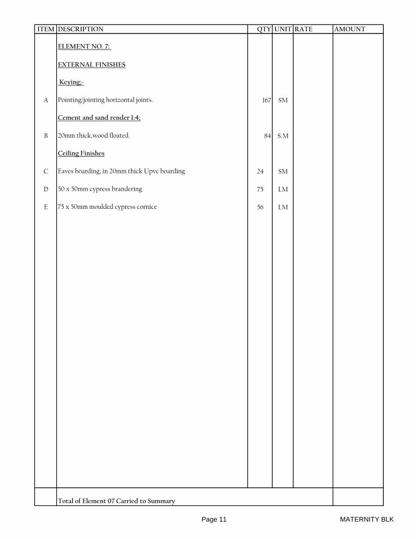
ITEM DESCRIPTION QTY UNIT RATE AMOUNT
ELEMENT NO. 7:
EXTERNAL FINISHES
Keying;-
A Pointing/jointing horizontal joints. 167 SM
Cement and sand render 1:4;
B 20mm thick,wood floated. 84 S.M
Ceiling Finishes
C Eaves boarding; in 20mm thick Upvc boarding 24 SM
D 50 x 50mm cypress brandering 75 LM
E 75 x 50mm moulded cypress cornice 56 LM
Total of Element 07 Carried to Summary
Page 11 MATERNITY BLK

ITEM DESCRIPTION QTY UNIT RATE AMOUNT
ELEMENT NO. 8:
INTERNAL FINISHES
FLOOR
Ceramic tiles (non-slip)
(Wet Areas)
A 30mm thick cement and sand (1:4) screed wood floated to receive ceramic tiles (m/s) 40 SM
B 250x250x8mm as manufactured by SAJ CERAMICS LTD. or other approved coloured ceramic non-slip floor tiles bedded and jointed in cement and sand 1:1 and pointed in coloured cement grouting
40 SM
C Ditto; but 100mm high skirting 45 LM
D 15mm thick cement and sand (1:4) screed wood floated to receive terazzo (m/s) 170 SM
E 25mm Terrazzo: first coat of cement and sand (1:3); second of cement and local marble chippings (1:2); machine polished smooth.
170 SM
F 20 x 100 mm high skirting with rounded top edge and coved at junction to paving 128 LM
G Plastic dividing strip 121 LM
WALL
15mm thick cement and sand (1:4) plaster in two coats; the first 9mm thick comprising cement, lime and sand (1:2:9) and the second 6mm second comprising cement lime and sand (1:1:6) to;
H Plaster to walls 688 SM
I Plaster to beams. 79 SM
J Plaster to columns. 30 SM
K Plaster to jambs/reveals. 17 SM
Wall tiling
L 20mm thick cement and sand (1:4) backing wood floated to receive ceramic tiles (m/s) 121 SM
M 250x250x8mm as manufactured by SAJ CERAMICS LTD. or other approved glazed white wall tiles bedded in cement and sand 1:1 and pointed in white cement grouting 121 SM
Total to Collection
Page 12 MATERNITY BLK

ITEM DESCRIPTION QTY UNIT RATE AMOUNT
A 100mm high decorative strip 20 LM
B Plastic edging to tiles 42 LM
CEILING
Sawn cypress
C Brandering, size 50x50mm 376 LM
Chipboard ceiling board.
D 12mm thick. 190 SM
E Extra for forming trap door with cypress framing, size 600x600mm2 NO
Wrought cypress.
F Moulded cornice plugged size, 100x50mm 200 LM
Total to Collection
Collection
Brought forward from page 12
Brought down from above
Total of Element 08 Carried to Summary
Page 13 MATERNITY BLK
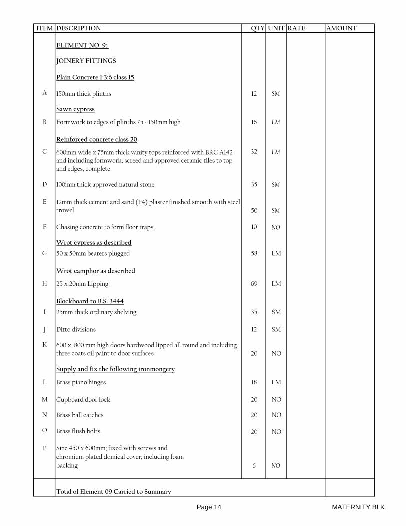
ITEM DESCRIPTION QTY UNIT RATE AMOUNT
ELEMENT NO. 9:
JOINERY FITTINGS
Plain Concrete 1:3:6 class 15
A 150mm thick plinths 12 SM
Sawn cypress
B Formwork to edges of plinths 75 - 150mm high 16 LM
Reinforced concrete class 20
C 600mm wide x 75mm thick vanity tops reinforced with BRC A142 and including formwork, screed and approved ceramic tiles to top and edges; complete
32 LM
D 100mm thick approved natural stone 35 SM
E 12mm thick cement and sand (1:4) plaster finished smooth with steel trowel 50 SM
F Chasing concrete to form floor traps 10 NO
Wrot cypress as described
G 50 x 50mm bearers plugged 58 LM
Wrot camphor as described
H 25 x 20mm Lipping 69 LM
Blockboard to B.S. 3444
I 25mm thick ordinary shelving 35 SM
J Ditto divisions 12 SM
K 600 x 800 mm high doors hardwood lipped all round and including three coats oil paint to door surfaces 20 NO
Supply and fix the following ironmongery
L Brass piano hinges 18 LM
M Cupboard door lock 20 NO
N Brass ball catches 20 NO
O Brass flush bolts 20 NO
P Size 450 x 600mm; fixed with screws and
chromium plated domical cover; including foam
backing 6 NO
Total of Element 09 Carried to Summary
Page 14 MATERNITY BLK
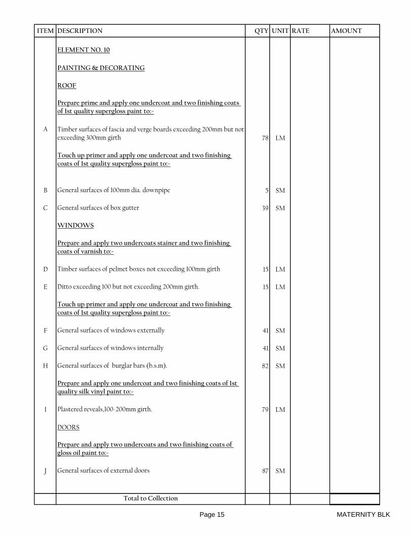
ITEM DESCRIPTION QTY UNIT RATE AMOUNT
ELEMENT NO. 10
PAINTING & DECORATING
ROOF
Prepare prime and apply one undercoat and two finishing coats of 1st quality supergloss paint to:-
A Timber surfaces of fascia and verge boards exceeding 200mm but not exceeding 300mm girth 78 LM
Touch up primer and apply one undercoat and two finishing coats of 1st quality supergloss paint to:-
B General surfaces of 100mm dia. downpipe 5 SM
C General surfaces of box gutter 39 SM
WINDOWS
Prepare and apply two undercoats stainer and two finishing coats of varnish to:-
D Timber surfaces of pelmet boxes not exceeding 100mm girth 15 LM
E Ditto exceeding 100 but not exceeding 200mm girth. 15 LM
Touch up primer and apply one undercoat and two finishing coats of 1st quality supergloss paint to:-
F General surfaces of windows externally 41 SM
G General surfaces of windows internally 41 SM
H General surfaces of burglar bars (b.s.m). 82 SM
Prepare and apply one undercoat and two finishing coats of 1st quality silk vinyl paint to:-
I Plastered reveals,100-200mm girth. 79 LM
DOORS
Prepare and apply two undercoats and two finishing coats of gloss oil paint to:-
J General surfaces of external doors 87 SM
Total to Collection
Page 15 MATERNITY BLK
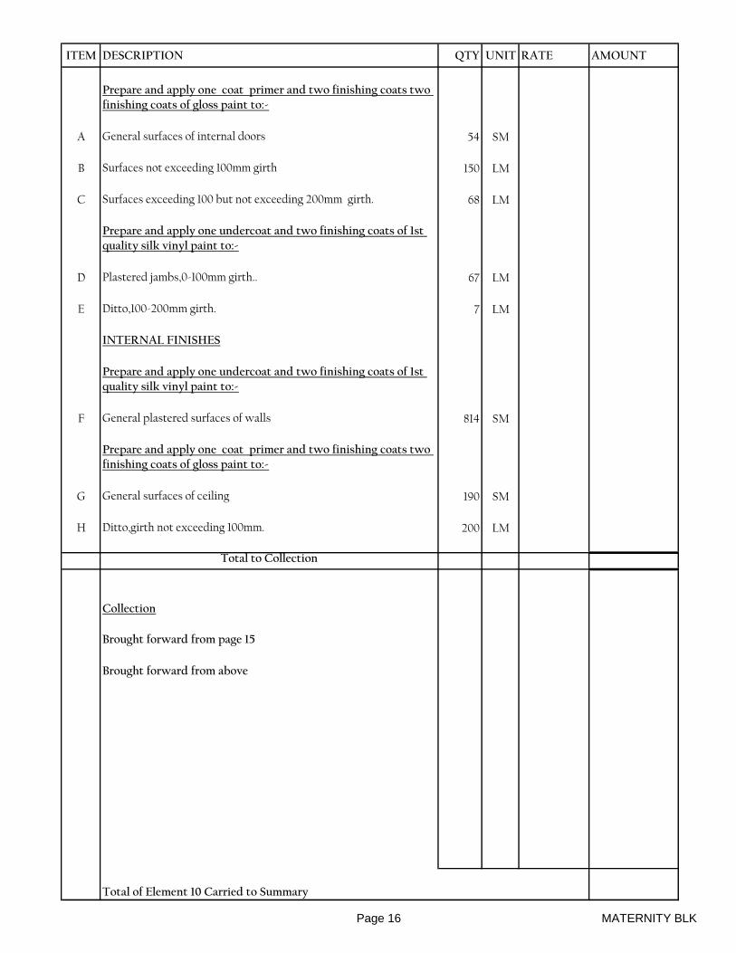
ITEM DESCRIPTION QTY UNIT RATE AMOUNT
Prepare and apply one coat primer and two finishing coats two finishing coats of gloss paint to:-
A General surfaces of internal doors 54 SM
B Surfaces not exceeding 100mm girth 150 LM
C Surfaces exceeding 100 but not exceeding 200mm girth. 68 LM
Prepare and apply one undercoat and two finishing coats of 1st quality silk vinyl paint to:-
D Plastered jambs,0-100mm girth.. 67 LM
E Ditto,100-200mm girth. 7 LM
INTERNAL FINISHES
Prepare and apply one undercoat and two finishing coats of 1st quality silk vinyl paint to:-
F General plastered surfaces of walls 814 SM
Prepare and apply one coat primer and two finishing coats two finishing coats of gloss paint to:-
G General surfaces of ceiling 190 SM
H Ditto,girth not exceeding 100mm. 200 LM
Total to Collection
Collection
Brought forward from page 15
Brought forward from above
Total of Element 10 Carried to Summary
Page 16 MATERNITY BLK

ITEM DESCRIPTION QTY UNIT RATE AMOUNT
SUMMARY
1 Substructure
2 Reinforced Concrete Superstructure
3 Superstructure Walling
4 Roof Construction, Covering & Rainwater Disposal
5 Windows
6 Doors
7 External Finishes
8 Internal Finishes
9 Joinery and Fittings
10 Painting and Decorating
TOTAL FOR MATERNITY BLOCK CARRIED TO MAIN SUMMARY..
Page 17 MATERNITY BLK
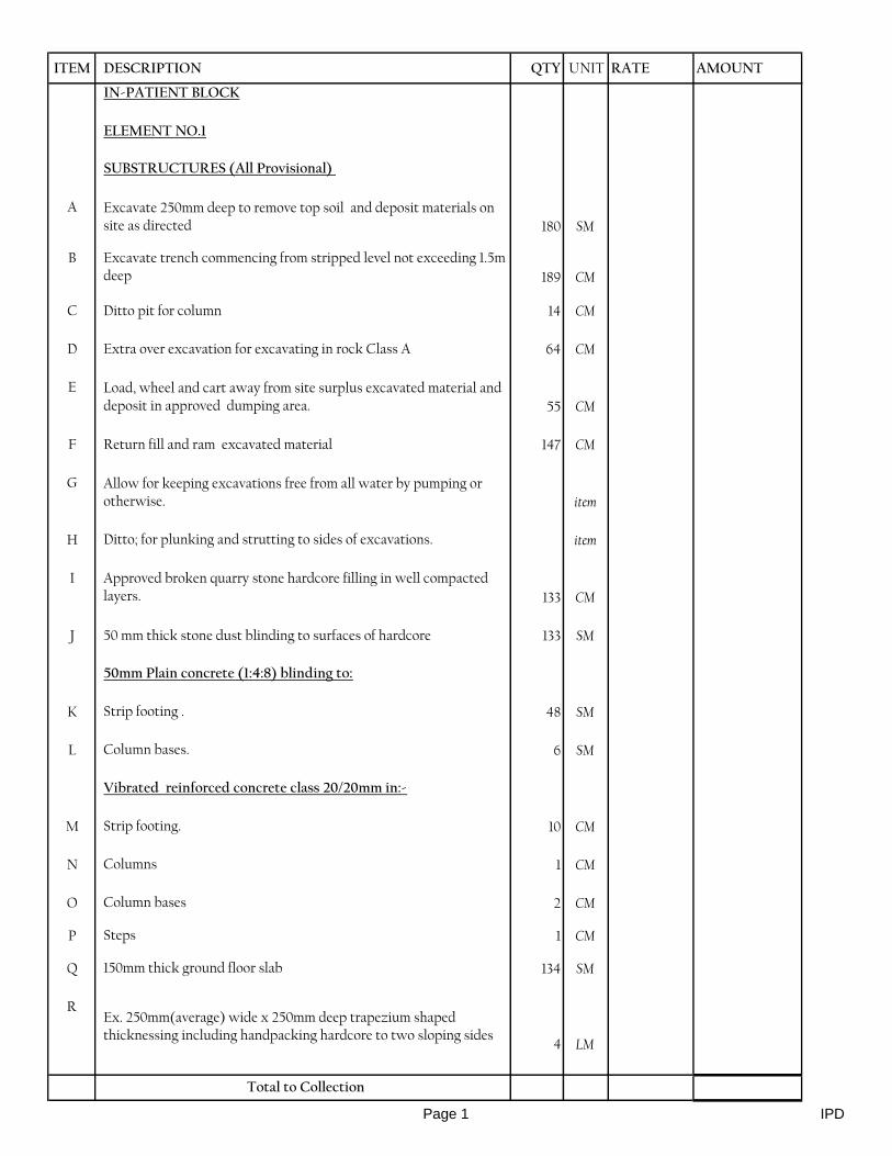
ITEM DESCRIPTION QTY UNIT RATE AMOUNT
IN-PATIENT BLOCK
ELEMENT NO.1
SUBSTRUCTURES (All Provisional)
A Excavate 250mm deep to remove top soil and deposit materials on site as directed 180 SM
B Excavate trench commencing from stripped level not exceeding 1.5m deep 189 CM
C Ditto pit for column 14 CM
D Extra over excavation for excavating in rock Class A 64 CM
E Load, wheel and cart away from site surplus excavated material and deposit in approved dumping area. 55 CM
F Return fill and ram excavated material 147 CM
G Allow for keeping excavations free from all water by pumping or otherwise. item
H Ditto; for plunking and strutting to sides of excavations. item
I Approved broken quarry stone hardcore filling in well compacted layers. 133 CM
J 50 mm thick stone dust blinding to surfaces of hardcore 133 SM
50mm Plain concrete (1:4:8) blinding to:
K Strip footing . 48 SM
L Column bases. 6 SM
Vibrated reinforced concrete class 20/20mm in:-
M Strip footing. 10 CM
N Columns 1 CM
O Column bases 2 CM
P Steps 1 CM
Q 150mm thick ground floor slab 134 SM
REx. 250mm(average) wide x 250mm deep trapezium shaped thicknessing including handpacking hardcore to two sloping sides
4 LM
Total to Collection
Page 1 IPD

ITEM DESCRIPTION QTY UNIT RATE AMOUNT
Damp proof membrane
A 1000 gauge polythene laid under surface beds 134 SM
Anti-termite treatment
B Chemical anti-termite treatment executed by an approved specialist under a ten year guarantee to surfaces of hardcore 134 SM
Reinforcement (all provisional)
High yield deformed steel bar reinforcement to BS4461
C 12mm diameter 600 Kg
D 10mm diameter 500 Kg
E 8mm diameter 100 Kg
Steel mesh fabric reinforcement to BS 4483
F Layer of mesh fabric reinforcement laid in slab or bed with 200mm side and end laps (measured net- no allowance made for laps) Ref: A142 weighing 2.22kg per square metre 134 SM
Formwork
G Sides of foundations bases 42 SM
H Sides of column bases 10 SM
I Sides of columns 56 SM
J Edges of beds, etc 75-150mm high 43 LM
Approved load bearing natural stone rough dressed walling in cement and sand mortar
K Walling thickness 225mm 189 SM
L 20 gauge hoop iron ties 25mm wide and 450mm girth cast into concrete one end and built into mortar joint of walling 87 No.
Bituminous felt damp proof courses laid on and including levelling screed of cement mortar
M In walling, width 200mm 105 LM
Total to Collection
Page 2 IPD
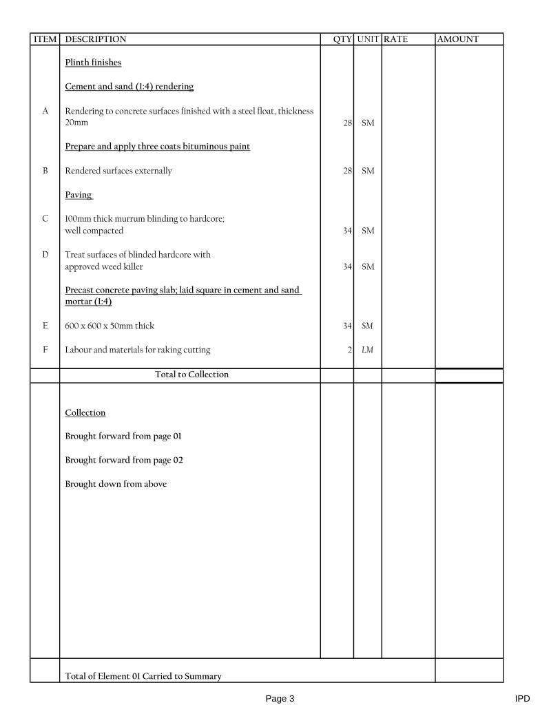
ITEM DESCRIPTION QTY UNIT RATE AMOUNT
Plinth finishes
Cement and sand (1:4) rendering
A Rendering to concrete surfaces finished with a steel float, thickness 20mm 28 SM
Prepare and apply three coats bituminous paint
B Rendered surfaces externally 28 SM
Paving
C 100mm thick murrum blinding to hardcore;
well compacted 34 SM
D Treat surfaces of blinded hardcore with
approved weed killer 34 SM
Precast concrete paving slab; laid square in cement and sand mortar (1:4)
E 600 x 600 x 50mm thick 34 SM
F Labour and materials for raking cutting 2 LM
Total to Collection
Collection
Brought forward from page 01
Brought forward from page 02
Brought down from above
Total of Element 01 Carried to Summary
Page 3 IPD
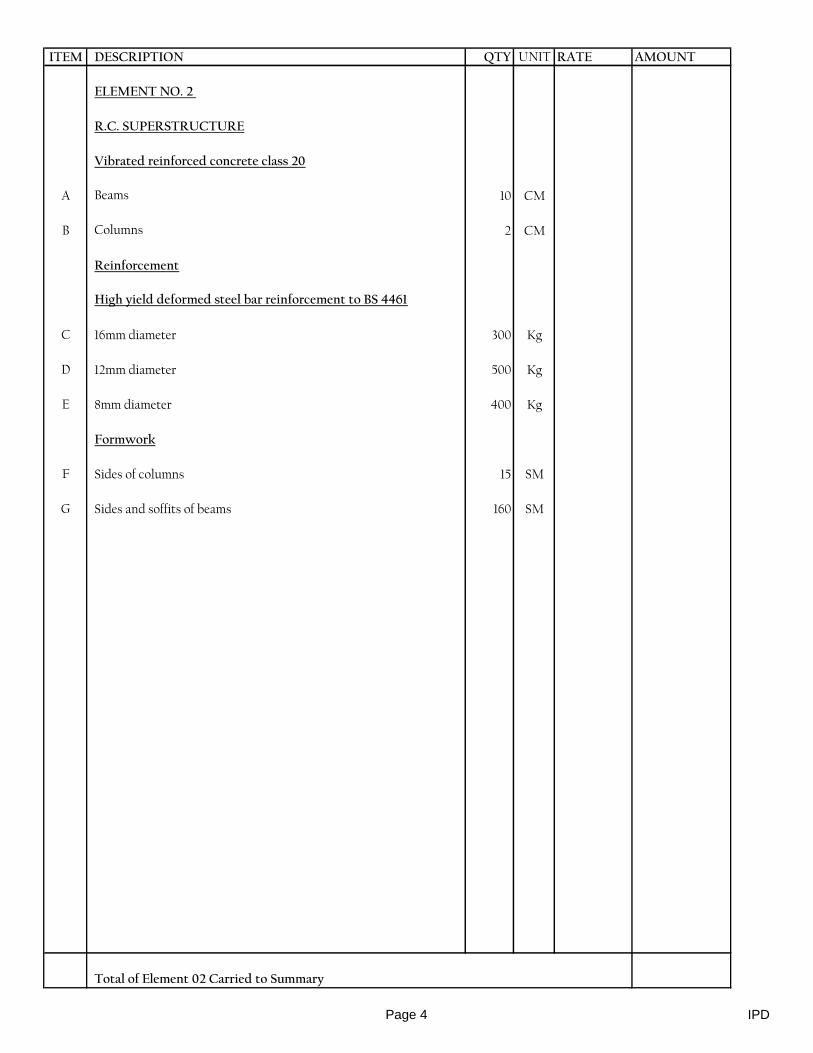
ITEM DESCRIPTION QTY UNIT RATE AMOUNT
ELEMENT NO. 2
R.C. SUPERSTRUCTURE
Vibrated reinforced concrete class 20
A Beams 10 CM
B Columns 2 CM
Reinforcement
High yield deformed steel bar reinforcement to BS 4461
C 16mm diameter 300 Kg
D 12mm diameter 500 Kg
E 8mm diameter 400 Kg
Formwork
F Sides of columns 15 SM
G Sides and soffits of beams 160 SM
Total of Element 02 Carried to Summary
Page 4 IPD
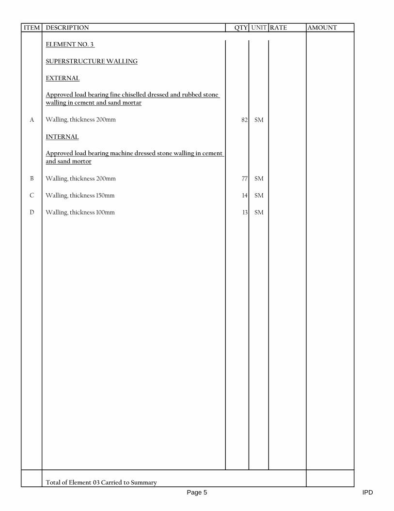
ITEM DESCRIPTION QTY UNIT RATE AMOUNT
ELEMENT NO. 3
SUPERSTRUCTURE WALLING
EXTERNAL
Approved load bearing fine chiselled dressed and rubbed stone walling in cement and sand mortar
A Walling, thickness 200mm 82 SM
INTERNAL
Approved load bearing machine dressed stone walling in cement and sand mortor
B Walling, thickness 200mm 77 SM
C Walling, thickness 150mm 14 SM
D Walling, thickness 100mm 13 SM
Total of Element 03 Carried to Summary
Page 5 IPD
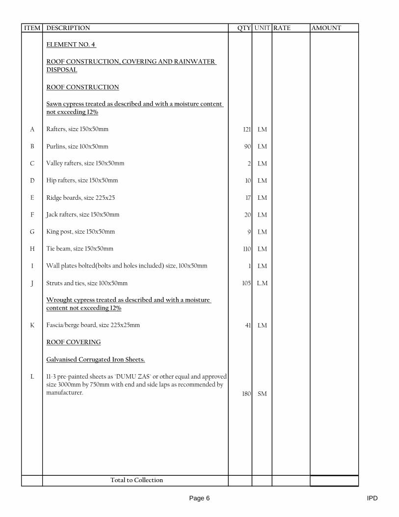
ITEM DESCRIPTION QTY UNIT RATE AMOUNT
ELEMENT NO. 4
ROOF CONSTRUCTION, COVERING AND RAINWATER DISPOSAL
ROOF CONSTRUCTION
Sawn cypress treated as described and with a moisture content not exceeding 12%
A Rafters, size 150x50mm 121 LM
B Purlins, size 100x50mm 90 LM
C Valley rafters, size 150x50mm 2 LM
D Hip rafters, size 150x50mm 10 LM
E Ridge boards, size 225x25 17 LM
F Jack rafters, size 150x50mm 20 LM
G King post, size 150x50mm 9 LM
H Tie beam, size 150x50mm 110 LM
I Wall plates bolted(bolts and holes included) size, 100x50mm 1 LM
J Struts and ties, size 100x50mm 105 L.M
Wrought cypress treated as described and with a moisture content not exceeding 12%
K Fascia/berge board, size 225x25mm 41 LM
ROOF COVERING
Galvanised Corrugated Iron Sheets.
L 11-3 pre-painted sheets as `DUMU ZAS` or other equal and approved size 3000mm by 750mm with end and side laps as recommended by manufacturer. 180 SM
Total to Collection
Page 6 IPD
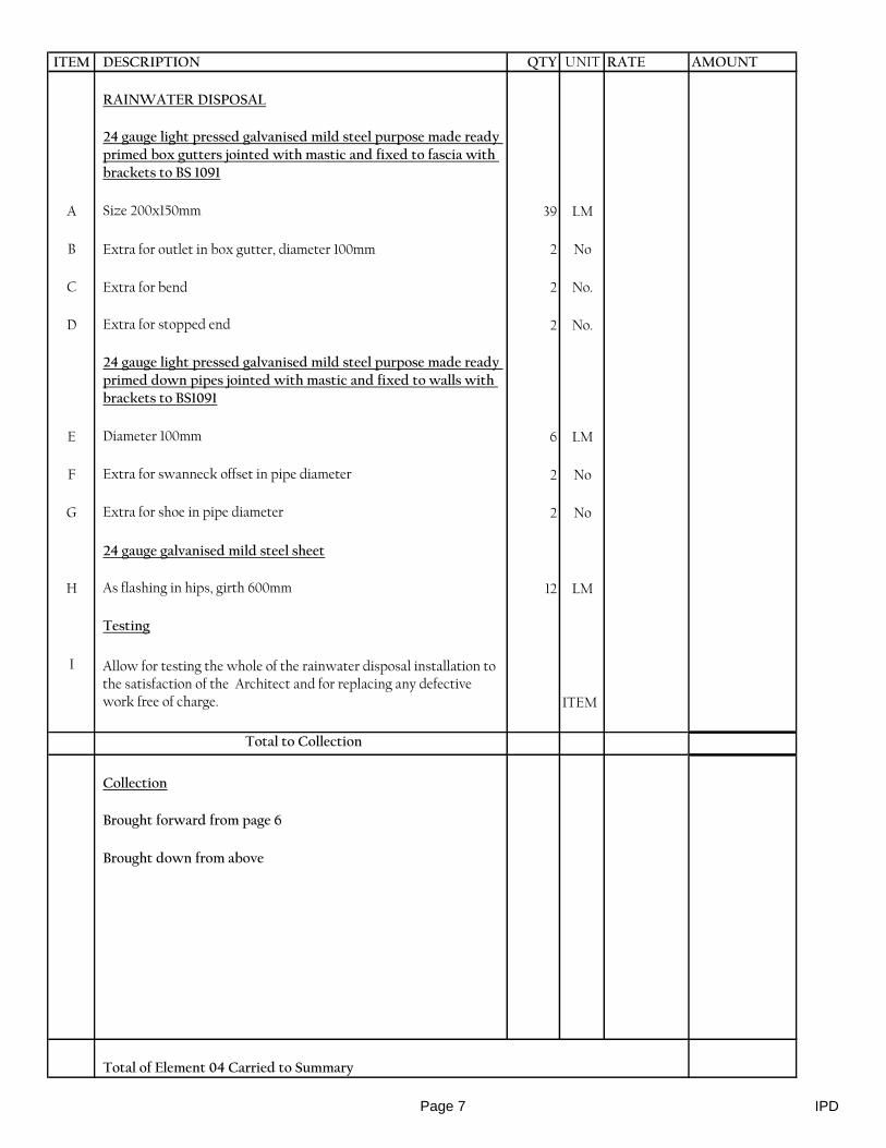
ITEM DESCRIPTION QTY UNIT RATE AMOUNT
RAINWATER DISPOSAL
24 gauge light pressed galvanised mild steel purpose made ready primed box gutters jointed with mastic and fixed to fascia with brackets to BS 1091
A Size 200x150mm 39 LM
B Extra for outlet in box gutter, diameter 100mm 2 No
C Extra for bend 2 No.
D Extra for stopped end 2 No.
24 gauge light pressed galvanised mild steel purpose made ready primed down pipes jointed with mastic and fixed to walls with brackets to BS1091
E Diameter 100mm 6 LM
F Extra for swanneck offset in pipe diameter 2 No
G Extra for shoe in pipe diameter 2 No
24 gauge galvanised mild steel sheet
H As flashing in hips, girth 600mm 12 LM
Testing
I Allow for testing the whole of the rainwater disposal installation to the satisfaction of the Architect and for replacing any defective work free of charge. ITEM
Total to Collection
Collection
Brought forward from page 6
Brought down from above
Total of Element 04 Carried to Summary
Page 7 IPD
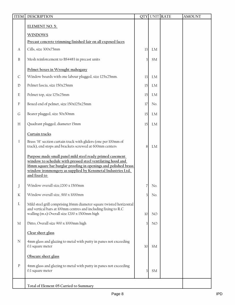
ITEM DESCRIPTION QTY UNIT RATE AMOUNT
ELEMENT NO. 5:
WINDOWS
Precast concrete trimming finished fair on all exposed faces
A Cills, size 300x75mm 13 LM
B Mesh reinforcement to BS4483 in precast units 3 SM
Pelmet boxes in Wrought mahogany
C Window boards with one labour plugged, size 125x25mm. 13 LM
D Pelmet fascia, size 150x25mm 15 LM
E Pelmet top, size 125x25mm 15 LM
F Boxed end of pelmet, size 150x125x25mm 17 No.
G Bearer plugged, size 50x50mm 15 LM
H Quadrant plugged, diameter 15mm 15 LM
Curtain tracks
I Brass "H" section curtain track with gliders (one per 100mm of track), end stops and brackets screwed at 600mm centers 8 LM
Purpose made small panel mild steel ready primed casement window to schedule with pressed steel ventilating hood and 16mm square bar burglar proofing in openings and polished brass window ironmongery as supplied by Kensmetal Industries Ltd. and fixed to
J Window overall size,1200 x 1500mm 7 No.
K Window overall size, 900 x 1000mm 3 No.
L Mild steel grill comprising 16mm diameter square twisted horizontal and vertical bars at 100mm centres and including fixing to R.C walling (m.s) Overall size 1200 x 1500mm high 10 NO
M Ditto, Overall size 900 x 1000mm high 3 NO
Clear sheet glass
N 4mm glass and glazing to metal with putty in panes not exceeding 0.1 square meter 30 SM
Obscure sheet glass
P 4mm glass and glazing to metal with putty in panes not exceeding 0.1 square meter 3 SM
Total of Element 05 Carried to Summary
Page 8 IPD
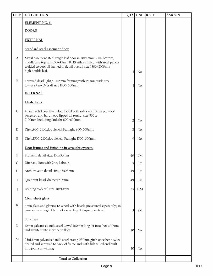
ITEM DESCRIPTION QTY UNIT RATE AMOUNT
ELEMENT NO. 6:
DOORS
EXTERNAL
Standard steel casement door
A Metal casement steel single leaf door in 50x45mm RHS bottom, middle and top rails, 50x45mm RHS stiles infilled with steel panels welded to door all framed to detail overall size 1800x2100mm high,double leaf. 1 No.
B Louvred dead light,50×45mm framing with 150mm wide steel louvres 4 no.Overall size 1800×600mm. 1 No.
INTERNAL
Flush doors
C 45 mm solid core flush door faced both sides with 3mm plywood veneered and hardwood lipped all round, size 800 x 2100mm.Including fanlight 800×600mm. 2 No.
D Ditto,900×2100,double leaf.Fanlight 900×600mm. 2 No.
E Ditto,1500×2100,double leaf.Fanlight 1500×600mm. 4 No.
Door frames and finishing in wrought cypress.
F Frame to detail size, 150x50mm 49 LM
G Ditto,mullion with 2no. Labour. 5 LM
H Architrave to detail size, 45x25mm 49 LM
I Quadrant bead, diameter 15mm 49 LM
J Beading to detail size, 10x10mm 35 L.M
Clear sheet glass
K 4mm glass and glazing to wood with beads (measured separately) in panes exceeding 0.1 but not exceeding 0.5 square meters 3 SM
Sundries
L 10mm galvanised mild steel dowel 100mm long let into foot of frame and grouted into mortice in floor 10 No.
M 25x1.6mm galvanised mild steel cramp 250mm girth once bent twice drilled and screwed to back of frame and with fish tailed end built into joints of walling. 30 No.
Total to Collection
Page 9 IPD

ITEM DESCRIPTION QTY UNIT RATE AMOUNT
Ironmongeryas per Union Catalogue or other equal and approved - supply and fix with matching screws
A 100mm pairs brass butt hinges 8 Prs
B 100mm pairs stainless steel double action spring hinges 4 Prs
C Three lever mortice lock with polished brass lever furniture 5 No.
D Three lever rebated mortice lock complete with furniture 1 No.
E Overhead door closer ; cat. No. 8823 3 No.
F 830 x 200 x 2mm Thick aluminium kick plate 3 SET
G 38mm rubber door stop fixed with rawl bolt 7 No.
H Floor spring double action Ref. Yale 913.02 90º S.O 4 NO.
Total to Collection
Collection
Brought forward from page 9
Brought down from above
Total of Element 06 Carried to Summary
Page 10 IPD
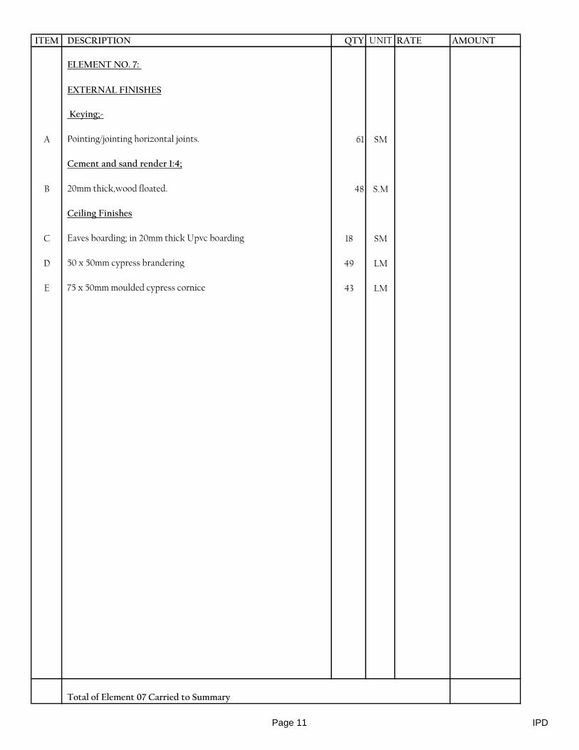
ITEM DESCRIPTION QTY UNIT RATE AMOUNT
ELEMENT NO. 7:
EXTERNAL FINISHES
Keying;-
A Pointing/jointing horizontal joints. 61 SM
Cement and sand render 1:4;
B 20mm thick,wood floated. 48 S.M
Ceiling Finishes
C Eaves boarding; in 20mm thick Upvc boarding 18 SM
D 50 x 50mm cypress brandering 49 LM
E 75 x 50mm moulded cypress cornice 43 LM
Total of Element 07 Carried to Summary
Page 11 IPD
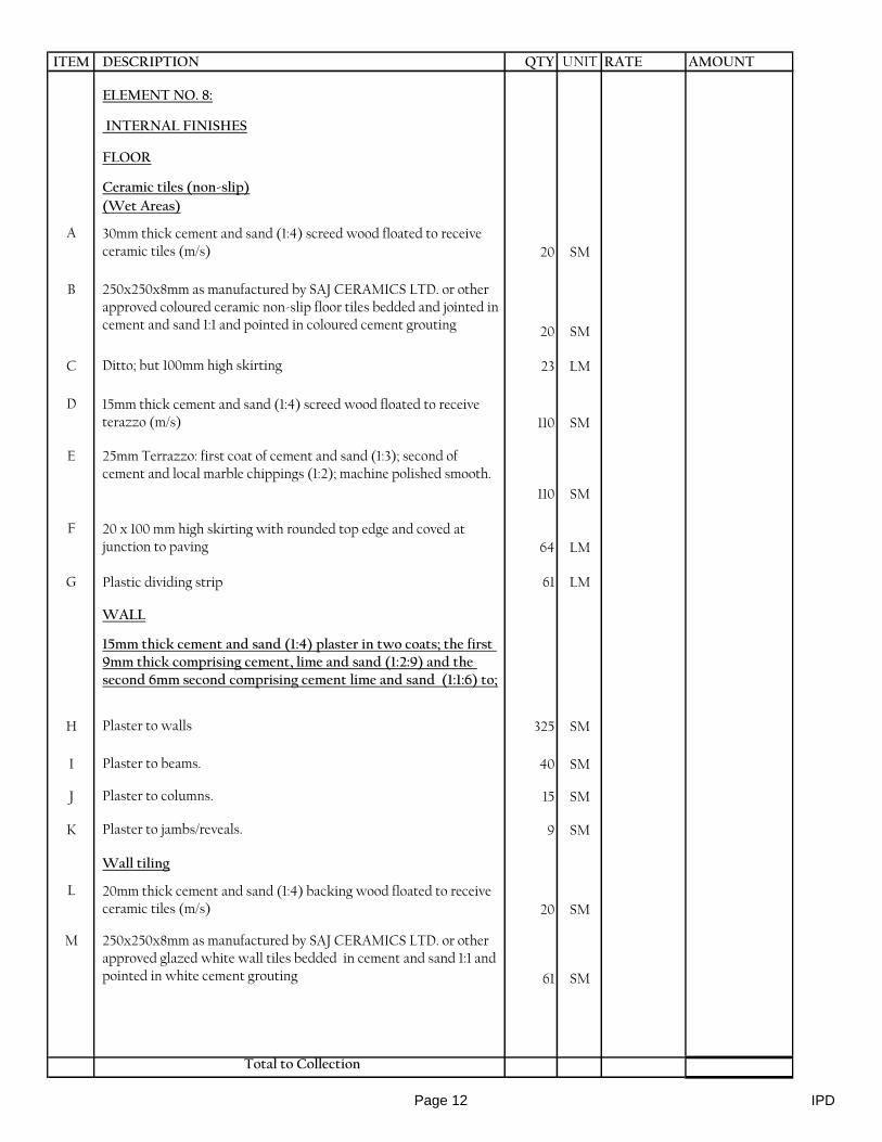
ITEM DESCRIPTION QTY UNIT RATE AMOUNT
ELEMENT NO. 8:
INTERNAL FINISHES
FLOOR
Ceramic tiles (non-slip)
(Wet Areas)
A 30mm thick cement and sand (1:4) screed wood floated to receive ceramic tiles (m/s) 20 SM
B 250x250x8mm as manufactured by SAJ CERAMICS LTD. or other approved coloured ceramic non-slip floor tiles bedded and jointed in cement and sand 1:1 and pointed in coloured cement grouting 20 SM
C Ditto; but 100mm high skirting 23 LM
D 15mm thick cement and sand (1:4) screed wood floated to receive terazzo (m/s) 110 SM
E 25mm Terrazzo: first coat of cement and sand (1:3); second of cement and local marble chippings (1:2); machine polished smooth.
110 SM
F 20 x 100 mm high skirting with rounded top edge and coved at junction to paving 64 LM
G Plastic dividing strip 61 LM
WALL
15mm thick cement and sand (1:4) plaster in two coats; the first 9mm thick comprising cement, lime and sand (1:2:9) and the second 6mm second comprising cement lime and sand (1:1:6) to;
H Plaster to walls 325 SM
I Plaster to beams. 40 SM
J Plaster to columns. 15 SM
K Plaster to jambs/reveals. 9 SM
Wall tiling
L 20mm thick cement and sand (1:4) backing wood floated to receive ceramic tiles (m/s) 20 SM
M 250x250x8mm as manufactured by SAJ CERAMICS LTD. or other approved glazed white wall tiles bedded in cement and sand 1:1 and pointed in white cement grouting 61 SM
Total to Collection
Page 12 IPD

ITEM DESCRIPTION QTY UNIT RATE AMOUNT
A 100mm high decorative strip 10 LM
B Plastic edging to tiles 21 LM
CEILING
Sawn cypress
C Brandering, size 50x50mm 226 LM
Chipboard ceiling board.
D 12mm thick. 125 SM
E Extra for forming trap door with cypress framing, size 600x600mm1 NO
Wrought cypress.
D Moulded cornice plugged size, 100x50mm 105 LM
Total to Collection
Collection
Brought forward from page 12
Brought down from above
Total of Element 08 Carried to Summary
Page 13 IPD

ITEM DESCRIPTION QTY UNIT RATE AMOUNT
ELEMENT NO. 9:
JOINERY FITTINGS
Plain Concrete 1:3:6 class 15
A 150mm thick plinths 6 SM
Sawn cypress
B Formwork to edges of plinths 75 - 150mm high 8 LM
Reinforced concrete class 20
C 600mm wide x 75mm thick vanity tops reinforced with BRC A142 and including formwork, screed and approved ceramic tiles to top and edges; complete
16 LM
D 100mm thick approved natural stone 18 SM
E 12mm thick cement and sand (1:4) plaster finished smooth with steel trowel 25 SM
F Chasing concrete to form floor traps 5 NO
Wrot cypress as described
G 50 x 50mm bearers plugged 29 LM
Wrot camphor as described
H 25 x 20mm Lipping 35 LM
Blockboard to B.S. 3444
I 25mm thick ordinary shelving 18 SM
J Ditto divisions 6 SM
K 600 x 800 mm high doors hardwood lipped all round and including three coats oil paint to door surfaces 10 NO
Supply and fix the following ironmongery
L Brass piano hinges 9 LM
M Cupboard door lock 10 NO
N Brass ball catches 10 NO
O Brass flush bolts 10 NO
P Size 450 x 600mm; fixed with screws and
chromium plated domical cover; including foam
backing 3 NO
Total of Element 09 Carried to Summary
Page 14 IPD
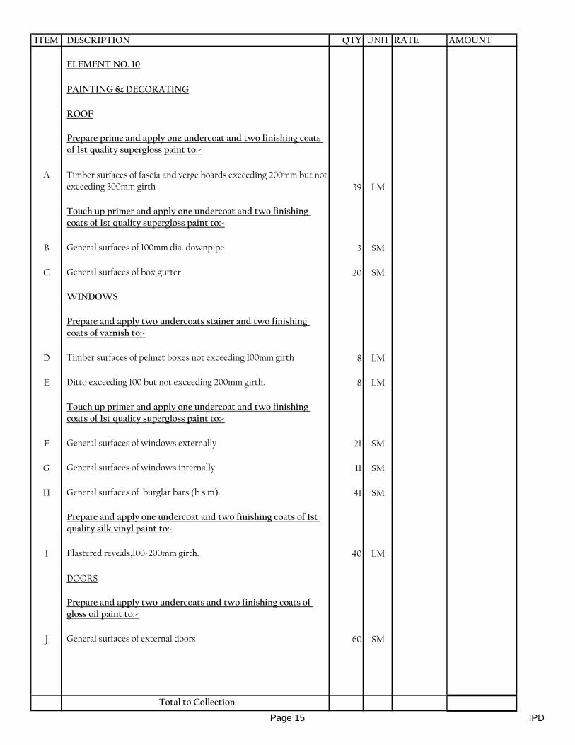
ITEM DESCRIPTION QTY UNIT RATE AMOUNT
ELEMENT NO. 10
PAINTING & DECORATING
ROOF
Prepare prime and apply one undercoat and two finishing coats of 1st quality supergloss paint to:-
A Timber surfaces of fascia and verge boards exceeding 200mm but not exceeding 300mm girth 39 LM
Touch up primer and apply one undercoat and two finishing coats of 1st quality supergloss paint to:-
B General surfaces of 100mm dia. downpipe 3 SM
C General surfaces of box gutter 20 SM
WINDOWS
Prepare and apply two undercoats stainer and two finishing coats of varnish to:-
D Timber surfaces of pelmet boxes not exceeding 100mm girth 8 LM
E Ditto exceeding 100 but not exceeding 200mm girth. 8 LM
Touch up primer and apply one undercoat and two finishing coats of 1st quality supergloss paint to:-
F General surfaces of windows externally 21 SM
G General surfaces of windows internally 11 SM
H General surfaces of burglar bars (b.s.m). 41 SM
Prepare and apply one undercoat and two finishing coats of 1st quality silk vinyl paint to:-
I Plastered reveals,100-200mm girth. 40 LM
DOORS
Prepare and apply two undercoats and two finishing coats of gloss oil paint to:-
J General surfaces of external doors 60 SM
Total to Collection
Page 15 IPD
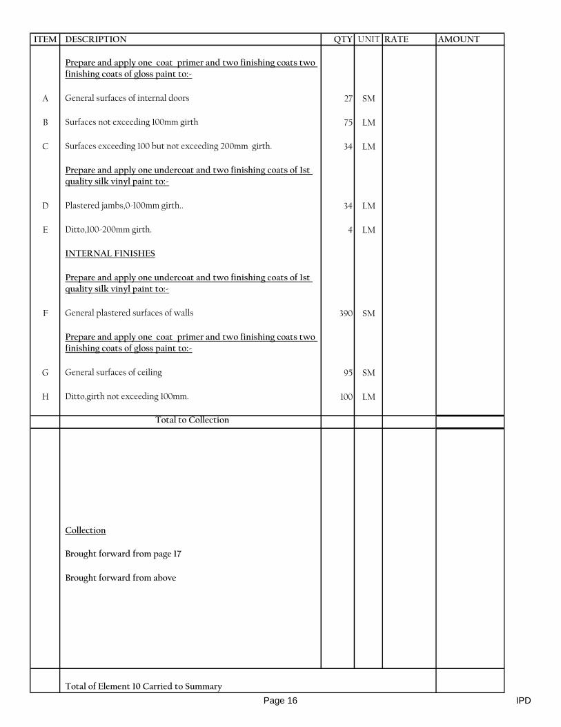
ITEM DESCRIPTION QTY UNIT RATE AMOUNT
Prepare and apply one coat primer and two finishing coats two finishing coats of gloss paint to:-
A General surfaces of internal doors 27 SM
B Surfaces not exceeding 100mm girth 75 LM
C Surfaces exceeding 100 but not exceeding 200mm girth. 34 LM
Prepare and apply one undercoat and two finishing coats of 1st quality silk vinyl paint to:-
D Plastered jambs,0-100mm girth.. 34 LM
E Ditto,100-200mm girth. 4 LM
INTERNAL FINISHES
Prepare and apply one undercoat and two finishing coats of 1st quality silk vinyl paint to:-
F General plastered surfaces of walls 390 SM
Prepare and apply one coat primer and two finishing coats two finishing coats of gloss paint to:-
G General surfaces of ceiling 95 SM
H Ditto,girth not exceeding 100mm. 100 LM
Total to Collection
Collection
Brought forward from page 17
Brought forward from above
Total of Element 10 Carried to Summary
Page 16 IPD

ITEM DESCRIPTION QTY UNIT RATE AMOUNT
SUMMARY
1 Substructure
2 Reinforced Concrete Superstructure
3 Superstructure Walling
4 Roof Construction, Covering & Rainwater Disposal
5 Windows
6 Doors
7 External Finishes
8 Internal Finishes
9 Joinery and Fittings
10 Painting and Decorating
TOTAL FOR IPD BLOCK CARRIED TO MAIN SUMMARY
Page 17 IPD

ITEM DESCRIPTION QTY UNIT RATE AMOUNT
SANITARY BLOCK
ELEMENT NO.1
SUBSTRUCTURES (All Provisional)
A Excavate 250mm deep to remove top soil and deposit materials on site as directed 135 SM
B Excavate trench commencing from stripped level not exceeding 1.5m deep 189 CM
C Ditto pit for column 14 CM
D Extra over excavation for excavating in rock Class A 98 CM
E Load, wheel and cart away from site surplus excavated material and deposit in approved dumping area. 110 CM
F Return fill and ram excavated material 93 CM
G Allow for keeping excavations free from all water by pumping or otherwise. item
H Ditto; for plunking and strutting to sides of excavations. item
I Approved broken quarry stone hardcore filling in well compacted layers. 110 CM
J 50 mm thick stone dust blinding to surfaces of hardcore 112 SM
50mm Plain concrete (1:4:8) blinding to:
K Strip footing . 63 SM
L Column bases. 6 SM
Vibrated reinforced concrete class 20/20mm in:-
M Strip footing. 13 CM
N Columns 1 CM
O Column bases 2 CM
P Steps 1 CM
Q 150mm thick ground floor slab 112 SM
REx. 250mm(average) wide x 250mm deep trapezium shaped thicknessing including handpacking hardcore to two sloping sides
7 LM
Total to Collection
Page 1 sanitary blk
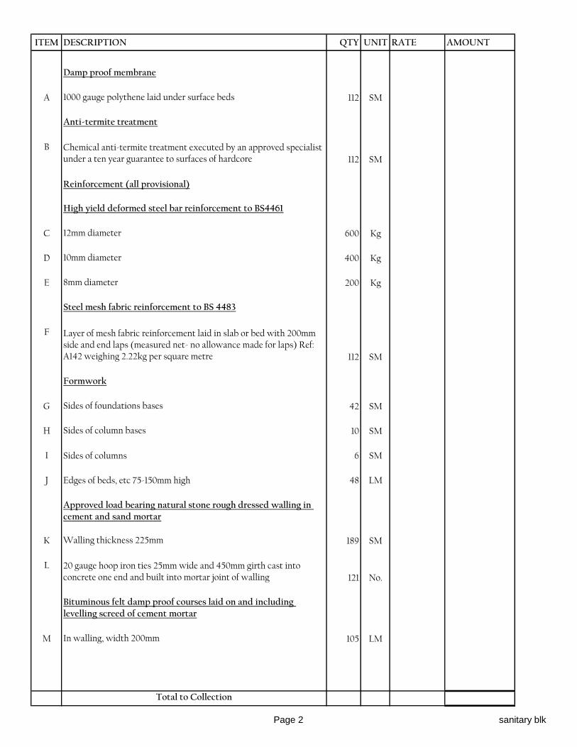
ITEM DESCRIPTION QTY UNIT RATE AMOUNT
Damp proof membrane
A 1000 gauge polythene laid under surface beds 112 SM
Anti-termite treatment
B Chemical anti-termite treatment executed by an approved specialist under a ten year guarantee to surfaces of hardcore 112 SM
Reinforcement (all provisional)
High yield deformed steel bar reinforcement to BS4461
C 12mm diameter 600 Kg
D 10mm diameter 400 Kg
E 8mm diameter 200 Kg
Steel mesh fabric reinforcement to BS 4483
F Layer of mesh fabric reinforcement laid in slab or bed with 200mm side and end laps (measured net- no allowance made for laps) Ref: A142 weighing 2.22kg per square metre 112 SM
Formwork
G Sides of foundations bases 42 SM
H Sides of column bases 10 SM
I Sides of columns 6 SM
J Edges of beds, etc 75-150mm high 48 LM
Approved load bearing natural stone rough dressed walling in cement and sand mortar
K Walling thickness 225mm 189 SM
L 20 gauge hoop iron ties 25mm wide and 450mm girth cast into concrete one end and built into mortar joint of walling 121 No.
Bituminous felt damp proof courses laid on and including levelling screed of cement mortar
M In walling, width 200mm 105 LM
Total to Collection
Page 2 sanitary blk

ITEM DESCRIPTION QTY UNIT RATE AMOUNT
Plinth finishes
Cement and sand (1:4) rendering
A Rendering to concrete surfaces finished with a steel float, thickness 20mm 48 SM
Prepare and apply three coats bituminous paint
B Rendered surfaces externally 48 SM
Paving
C 100mm thick murrum blinding to hardcore;
well compacted 23 SM
D Treat surfaces of blinded hardcore with
approved weed killer 23 SM
Precast concrete paving slab; laid square in cement and sand mortar (1:4)
E 600 x 600 x 50mm thick 23 SM
F Labour and materials for raking cutting 3 LM
Total to Collection
Collection
Brought forward from page 01
Brought forward from page 02
Brought down from above
Total of Element 01 Carried to Summary
Page 3 sanitary blk

ITEM DESCRIPTION QTY UNIT RATE AMOUNT
ELEMENT NO. 2
R.C. SUPERSTRUCTURE
Vibrated reinforced concrete class 20
A Beams 8 CM
B Columns 3 CM
Reinforcement
High yield deformed steel bar reinforcement to BS 4461
C 16mm diameter 200 Kg
D 12mm diameter 1000 Kg
E 8mm diameter 800 Kg
Formwork
F Sides of columns 30 SM
G Sides and soffits of beams 136 SM
Total of Element 02 Carried to Summary
Page 4 sanitary blk
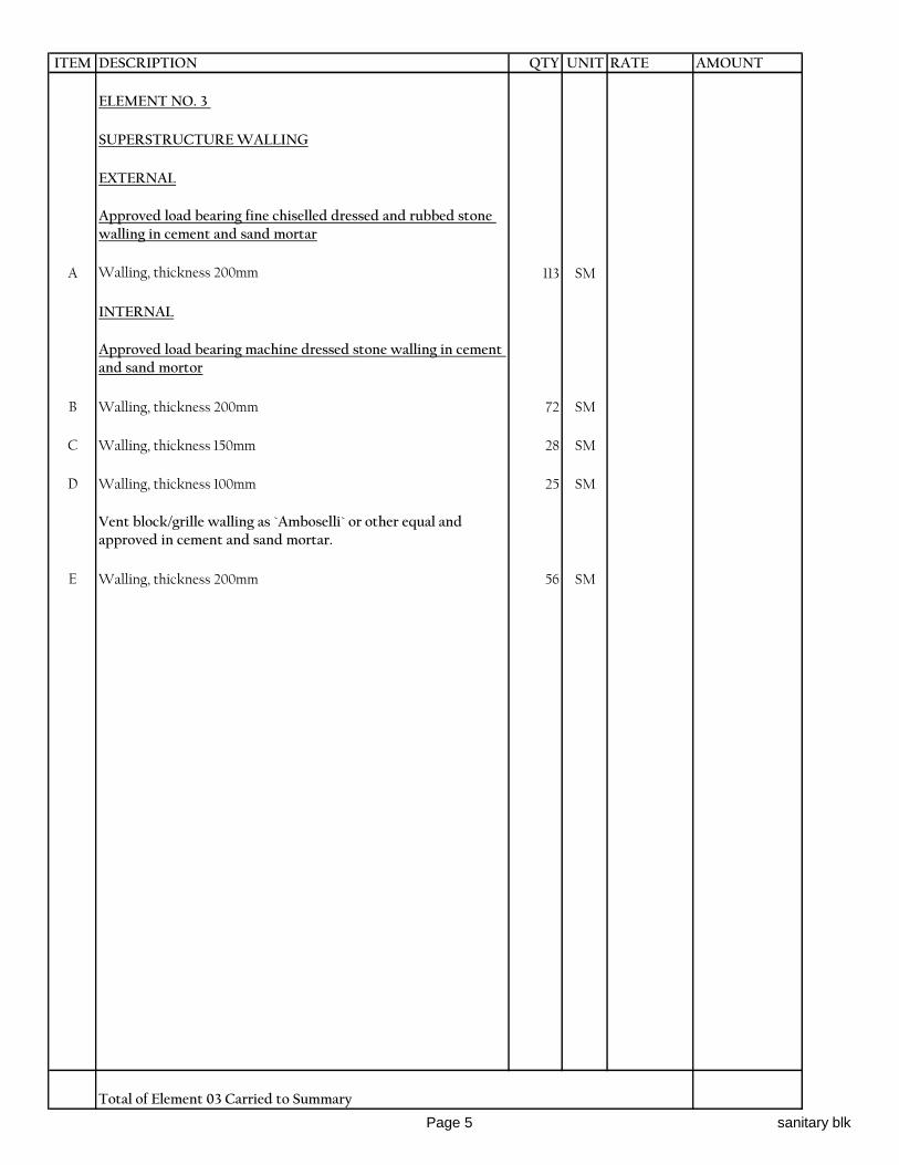
ITEM DESCRIPTION QTY UNIT RATE AMOUNT
ELEMENT NO. 3
SUPERSTRUCTURE WALLING
EXTERNAL
Approved load bearing fine chiselled dressed and rubbed stone walling in cement and sand mortar
A Walling, thickness 200mm 113 SM
INTERNAL
Approved load bearing machine dressed stone walling in cement and sand mortor
B Walling, thickness 200mm 72 SM
C Walling, thickness 150mm 28 SM
D Walling, thickness 100mm 25 SM
Vent block/grille walling as `Amboselli` or other equal and approved in cement and sand mortar.
E Walling, thickness 200mm 56 SM
Total of Element 03 Carried to Summary
Page 5 sanitary blk
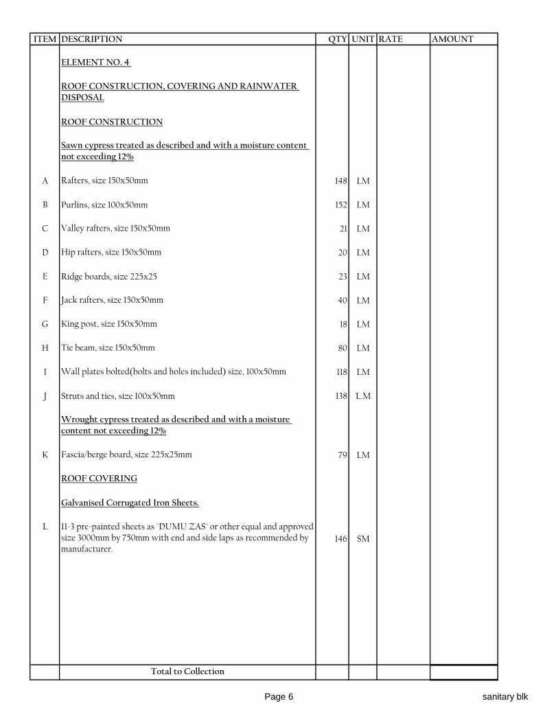
ITEM DESCRIPTION QTY UNIT RATE AMOUNT
ELEMENT NO. 4
ROOF CONSTRUCTION, COVERING AND RAINWATER DISPOSAL
ROOF CONSTRUCTION
Sawn cypress treated as described and with a moisture content not exceeding 12%
A Rafters, size 150x50mm 148 LM
B Purlins, size 100x50mm 152 LM
C Valley rafters, size 150x50mm 21 LM
D Hip rafters, size 150x50mm 20 LM
E Ridge boards, size 225x25 23 LM
F Jack rafters, size 150x50mm 40 LM
G King post, size 150x50mm 18 LM
H Tie beam, size 150x50mm 80 LM
I Wall plates bolted(bolts and holes included) size, 100x50mm 118 LM
J Struts and ties, size 100x50mm 138 L.M
Wrought cypress treated as described and with a moisture content not exceeding 12%
K Fascia/berge board, size 225x25mm 79 LM
ROOF COVERING
Galvanised Corrugated Iron Sheets.
L 11-3 pre-painted sheets as `DUMU ZAS` or other equal and approved size 3000mm by 750mm with end and side laps as recommended by manufacturer.
146 SM
Total to Collection
Page 6 sanitary blk
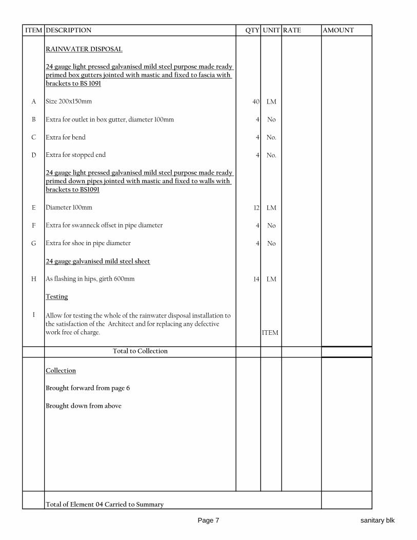
ITEM DESCRIPTION QTY UNIT RATE AMOUNT
RAINWATER DISPOSAL
24 gauge light pressed galvanised mild steel purpose made ready primed box gutters jointed with mastic and fixed to fascia with brackets to BS 1091
A Size 200x150mm 40 LM
B Extra for outlet in box gutter, diameter 100mm 4 No
C Extra for bend 4 No.
D Extra for stopped end 4 No.
24 gauge light pressed galvanised mild steel purpose made ready primed down pipes jointed with mastic and fixed to walls with brackets to BS1091
E Diameter 100mm 12 LM
F Extra for swanneck offset in pipe diameter 4 No
G Extra for shoe in pipe diameter 4 No
24 gauge galvanised mild steel sheet
H As flashing in hips, girth 600mm 14 LM
Testing
I Allow for testing the whole of the rainwater disposal installation to the satisfaction of the Architect and for replacing any defective work free of charge. ITEM
Total to Collection
Collection
Brought forward from page 6
Brought down from above
Total of Element 04 Carried to Summary
Page 7 sanitary blk

ITEM DESCRIPTION QTY UNIT RATE AMOUNT
ELEMENT NO. 5:
WINDOWS
Precast concrete trimming finished fair on all exposed faces
A Cills, size 300x75mm 11 LM
B Mesh reinforcement to BS4483 in precast units 5 SM
Pelmet boxes in Wrought mahogany
C Window boards with one labour plugged, size 125x25mm. 11 LM
D Pelmet fascia, size 150x25mm 13 LM
E Pelmet top, size 125x25mm 13 LM
F Boxed end of pelmet, size 150x125x25mm 24 No.
G Bearer plugged, size 50x50mm 13 LM
H Quadrant plugged, diameter 15mm 13 LM
Curtain tracks
I Brass "H" section curtain track with gliders (one per 100mm of track), end stops and brackets screwed at 600mm centers 13 LM
Purpose made small panel mild steel ready primed casement window to schedule with pressed steel ventilating hood and 16mm square bar burglar proofing in openings and polished brass window ironmongery as supplied by Kensmetal Industries Ltd. and fixed to
J Window overall size,1200 x 1500mm 6 No.
K Window overall size, 900 x 1000mm 6 No.
L Mild steel grill comprising 16mm diameter square twisted horizontal and vertical bars at 100mm centres and including fixing to R.C walling (m.s) Overall size 1200 x 1500mm high 6 NO
M Ditto, Overall size 900 x 1000mm high 6 NO
Clear sheet glass
N 4mm glass and glazing to metal with putty in panes not exceeding 0.1 square meter 11 SM
Obscure sheet glass
P 4mm glass and glazing to metal with putty in panes not exceeding 0.1 square meter 5 SM
Total of Element 05 Carried to Summary
Page 8 sanitary blk

ITEM DESCRIPTION QTY UNIT RATE AMOUNT
ELEMENT NO. 6:
DOORS
EXTERNAL
Standard steel casement door
A Metal casement steel single leaf door in 50x45mm RHS bottom, middle and top rails, 50x45mm RHS stiles infilled with steel panels welded to door all framed to detail overall size 1800x2100mm high,double leaf. 2 No.
B Louvred dead light,50×45mm framing with 150mm wide steel louvres 4 no.Overall size 1800×600mm. 2 No.
INTERNAL
Flush doors
C 45 mm solid core flush door faced both sides with 3mm plywood veneered and hardwood lipped all round, size 800 x 2100mm.Including fanlight 800×600mm. 10 No.
D Ditto,900×2100,double leaf.Fanlight 900×600mm. 5 No.
E Ditto,1500×2100,double leaf.Fanlight 1500×600mm. 1 No.
Door frames and finishing in wrought cypress.
F Frame to detail size, 150x50mm 84 LM
G Ditto,mullion with 2no. Labour. 12 LM
H Architrave to detail size, 45x25mm 84 LM
I Quadrant bead, diameter 15mm 84 LM
J Beading to detail size, 40x10mm 98 L.M
Clear sheet glass
K 4mm glass and glazing to wood with beads (measured separately) in panes exceeding 0.1 but not exceeding 0.5 square meters 4 SM
Sundries
L 10mm galvanised mild steel dowel 100mm long let into foot of frame and grouted into mortice in floor 60 No.
M 25x1.6mm galvanised mild steel cramp 250mm girth once bent twice drilled and screwed to back of frame and with fish tailed end built into joints of walling. 60 No.
Total to Collection
Page 9 sanitary blk

ITEM DESCRIPTION QTY UNIT RATE AMOUNT
Ironmongeryas per Union Catalogue or other equal and approved - supply and fix with matching screws
A 100mm pairs brass butt hinges 21 Prs
B 100mm pairs stainless steel double action spring hinges 2 Prs
C Three lever mortice lock with polished brass lever furniture 14 No.
D Three lever rebated mortice lock complete with furniture 1 No.
E Overhead door closer ; cat. No. 8823 2 No.
F 830 x 200 x 2mm Thick aluminium kick plate 8 SET
G 38mm rubber door stop fixed with rawl bolt 16 No.
H Floor spring double action Ref. Yale 913.02 90º S.O 1 NO.
Total to Collection
Collection
Brought forward from page 9
Brought down from above
Total of Element 06 Carried to Summary
Page 10 sanitary blk
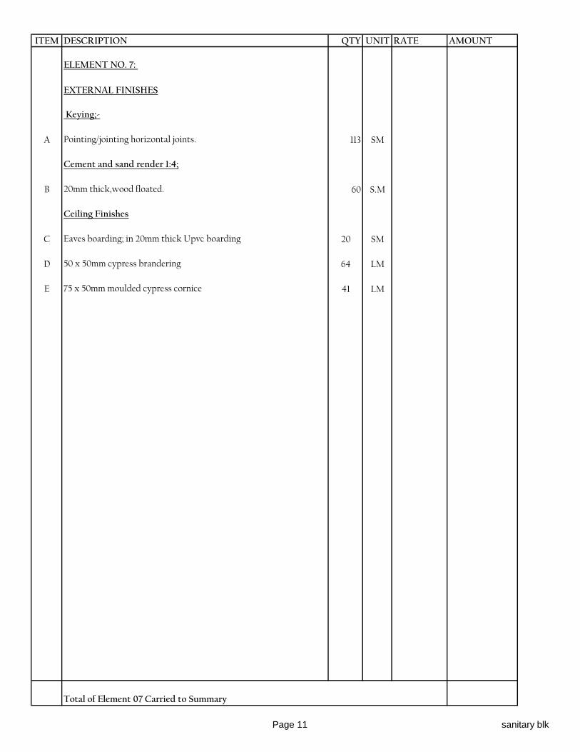
ITEM DESCRIPTION QTY UNIT RATE AMOUNT
ELEMENT NO. 7:
EXTERNAL FINISHES
Keying;-
A Pointing/jointing horizontal joints. 113 SM
Cement and sand render 1:4;
B 20mm thick,wood floated. 60 S.M
Ceiling Finishes
C Eaves boarding; in 20mm thick Upvc boarding 20 SM
D 50 x 50mm cypress brandering 64 LM
E 75 x 50mm moulded cypress cornice 41 LM
Total of Element 07 Carried to Summary
Page 11 sanitary blk

ITEM DESCRIPTION QTY UNIT RATE AMOUNT
ELEMENT NO. 8:
INTERNAL FINISHES
FLOOR
Ceramic tiles (non-slip)
(Wet Areas)
A 30mm thick cement and sand (1:4) screed wood floated to receive ceramic tiles (m/s) 40 SM
B 250x250x8mm as manufactured by SAJ CERAMICS LTD. or other approved coloured ceramic non-slip floor tiles bedded and jointed in cement and sand 1:1 and pointed in coloured cement grouting
40 SM
C Ditto; but 100mm high skirting 45 LM
D 15mm thick cement and sand (1:4) screed wood floated to receive terazzo (m/s) 72 SM
E 25mm Terrazzo: first coat of cement and sand (1:3); second of cement and local marble chippings (1:2); machine polished smooth.
72 SM
F 20 x 100 mm high skirting with rounded top edge and coved at junction to paving 98 LM
G Plastic dividing strip 84 LM
WALL
15mm thick cement and sand (1:4) plaster in two coats; the first 9mm thick comprising cement, lime and sand (1:2:9) and the second 6mm second comprising cement lime and sand (1:1:6) to;
H Plaster to walls 384 SM
I Plaster to beams. 28 SM
J Plaster to columns. 21 SM
K Plaster to jambs/reveals. 12 SM
Wall tiling
L 20mm thick cement and sand (1:4) backing wood floated to receive ceramic tiles (m/s) 89 SM
M 250x250x8mm as manufactured by SAJ CERAMICS LTD. or other approved glazed white wall tiles bedded in cement and sand 1:1 and pointed in white cement grouting 89 SM
Total to Collection
Page 12 sanitary blk
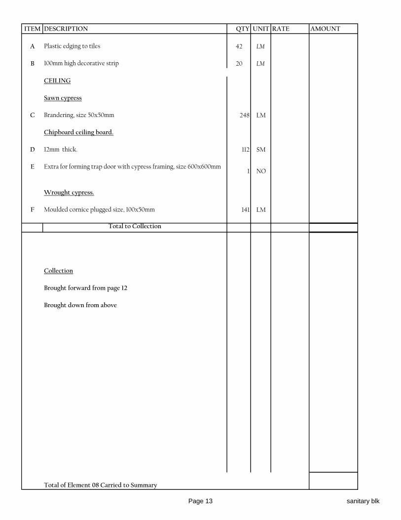
ITEM DESCRIPTION QTY UNIT RATE AMOUNT
A Plastic edging to tiles 42 LM
B 100mm high decorative strip 20 LM
CEILING
Sawn cypress
C Brandering, size 50x50mm 248 LM
Chipboard ceiling board.
D 12mm thick. 112 SM
E Extra for forming trap door with cypress framing, size 600x600mm1 NO
Wrought cypress.
F Moulded cornice plugged size, 100x50mm 141 LM
Total to Collection
Collection
Brought forward from page 12
Brought down from above
Total of Element 08 Carried to Summary
Page 13 sanitary blk
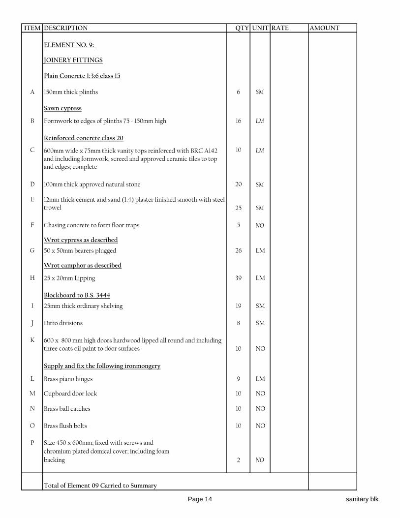
ITEM DESCRIPTION QTY UNIT RATE AMOUNT
ELEMENT NO. 9:
JOINERY FITTINGS
Plain Concrete 1:3:6 class 15
A 150mm thick plinths 6 SM
Sawn cypress
B Formwork to edges of plinths 75 - 150mm high 16 LM
Reinforced concrete class 20
C 600mm wide x 75mm thick vanity tops reinforced with BRC A142 and including formwork, screed and approved ceramic tiles to top and edges; complete
10 LM
D 100mm thick approved natural stone 20 SM
E 12mm thick cement and sand (1:4) plaster finished smooth with steel trowel 25 SM
F Chasing concrete to form floor traps 5 NO
Wrot cypress as described
G 50 x 50mm bearers plugged 26 LM
Wrot camphor as described
H 25 x 20mm Lipping 39 LM
Blockboard to B.S. 3444
I 25mm thick ordinary shelving 19 SM
J Ditto divisions 8 SM
K 600 x 800 mm high doors hardwood lipped all round and including three coats oil paint to door surfaces 10 NO
Supply and fix the following ironmongery
L Brass piano hinges 9 LM
M Cupboard door lock 10 NO
N Brass ball catches 10 NO
O Brass flush bolts 10 NO
P Size 450 x 600mm; fixed with screws and
chromium plated domical cover; including foam
backing 2 NO
Total of Element 09 Carried to Summary
Page 14 sanitary blk
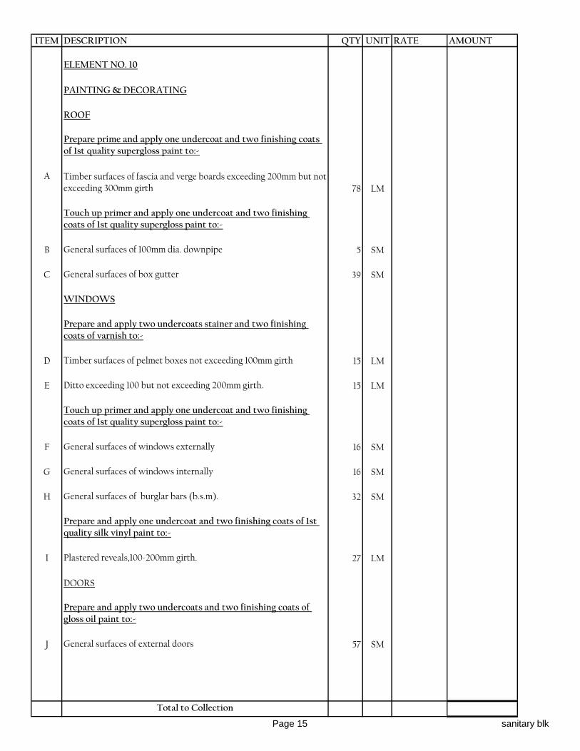
ITEM DESCRIPTION QTY UNIT RATE AMOUNT
ELEMENT NO. 10
PAINTING & DECORATING
ROOF
Prepare prime and apply one undercoat and two finishing coats of 1st quality supergloss paint to:-
A Timber surfaces of fascia and verge boards exceeding 200mm but not exceeding 300mm girth 78 LM
Touch up primer and apply one undercoat and two finishing coats of 1st quality supergloss paint to:-
B General surfaces of 100mm dia. downpipe 5 SM
C General surfaces of box gutter 39 SM
WINDOWS
Prepare and apply two undercoats stainer and two finishing coats of varnish to:-
D Timber surfaces of pelmet boxes not exceeding 100mm girth 15 LM
E Ditto exceeding 100 but not exceeding 200mm girth. 15 LM
Touch up primer and apply one undercoat and two finishing coats of 1st quality supergloss paint to:-
F General surfaces of windows externally 16 SM
G General surfaces of windows internally 16 SM
H General surfaces of burglar bars (b.s.m). 32 SM
Prepare and apply one undercoat and two finishing coats of 1st quality silk vinyl paint to:-
I Plastered reveals,100-200mm girth. 27 LM
DOORS
Prepare and apply two undercoats and two finishing coats of gloss oil paint to:-
J General surfaces of external doors 57 SM
Total to Collection
Page 15 sanitary blk

ITEM DESCRIPTION QTY UNIT RATE AMOUNT
Prepare and apply one coat primer and two finishing coats two finishing coats of gloss paint to:-
A General surfaces of internal doors 54 SM
B Surfaces not exceeding 100mm girth 150 LM
C Surfaces exceeding 100 but not exceeding 200mm girth. 68 LM
Prepare and apply one undercoat and two finishing coats of 1st quality silk vinyl paint to:-
D Plastered jambs,0-100mm girth.. 67 LM
E Ditto,100-200mm girth. 7 LM
INTERNAL FINISHES
Prepare and apply one undercoat and two finishing coats of 1st quality silk vinyl paint to:-
F General plastered surfaces of walls 415 SM
Prepare and apply one coat primer and two finishing coats two finishing coats of gloss paint to:-
G General surfaces of ceiling 112 SM
H Ditto,girth not exceeding 100mm. 124 LM
Total to Collection
Collection
Brought forward from page 15
Brought forward from above
Total of Element 10 Carried to Summary
Page 16 sanitary blk
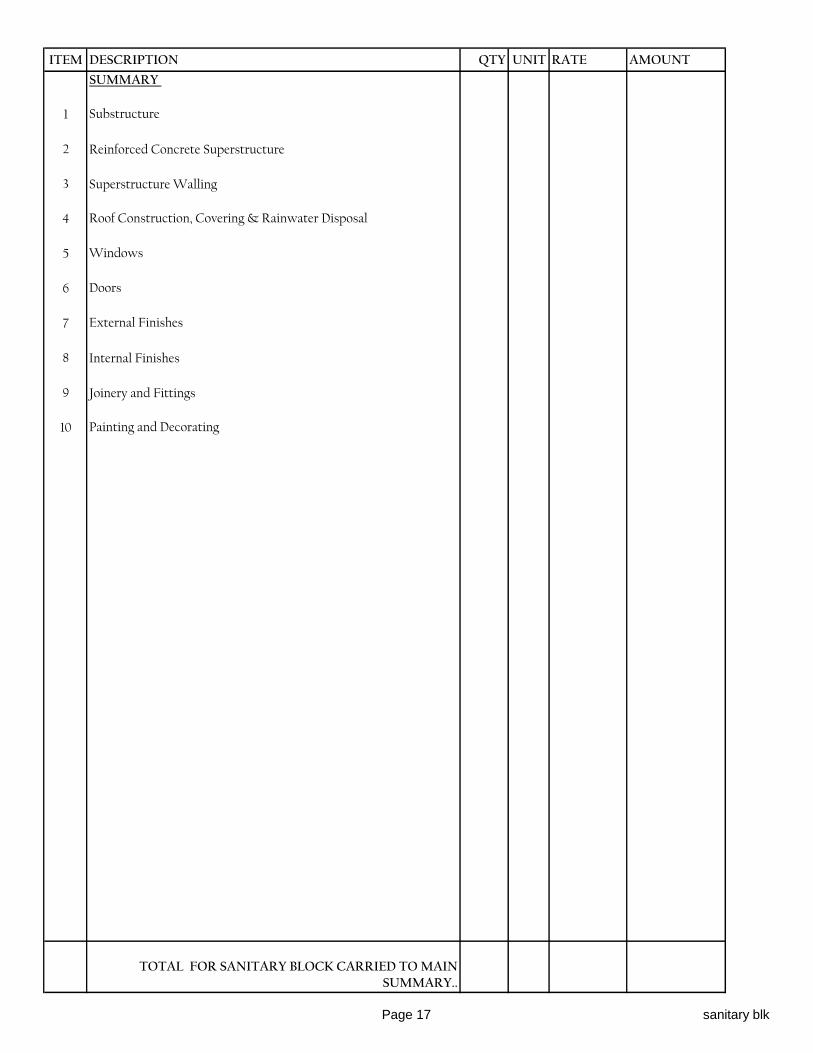
ITEM DESCRIPTION QTY UNIT RATE AMOUNT
SUMMARY
1 Substructure
2 Reinforced Concrete Superstructure
3 Superstructure Walling
4 Roof Construction, Covering & Rainwater Disposal
5 Windows
6 Doors
7 External Finishes
8 Internal Finishes
9 Joinery and Fittings
10 Painting and Decorating
TOTAL FOR SANITARY BLOCK CARRIED TO MAIN SUMMARY..
Page 17 sanitary blk

ITEMDESCRIPTION PAGE AMOUNT CTS
A SANITARY BLOCK 17
B MATERNITY BLOCK 17
C INPATIENT DEPARTMENT BLOCK 17
TOTAL CARRIED TO MAIN SUMMARY
BW SUMS/1

OLOLULUNG'A
Item Description Unit Qty Rate (Kshs) Amount (KShs)
SANITARY FITTINGS
Supply, deliver, install and fix the following
sanitary fittings including all materials and
jointing to supply, waste/soil and overflow
pipes.Twyfords Ltd products are specified only
as an indication of quality. Equal and approved
appliances may be supplied. Where trade names
are mentioned, the Ref. No. is intended only as a
Water Closet
A
Squatting water closet suite in vitreous china
comprising of water closet bowl with top plate and
integral foot threads, S-trap connector, 9 litres high
cistern and fittings and pull chain including siphon,
15mm dia side inlet ball valve, 20mm dia side
overflow, plastic flush pipe, inlet connector and
cistern supports. All to be as "Twyfords Oriental" or
approved equivalent.
No 9
Medical Wash Hand Basin
C
Counter top Twyfords "SOLA L.B.G/L" wash hand
basin with no tap holes and chain stay hole cat. No.
WB 1520WH, wall brackets cat no. SR 1315 xx
complete with "lever action mixer fitting, 1/2 with
swivel nozzle and divided flow" wall mounted mixer
cat. no. SF 1099 CP, chrome grid waste 11/4" cat no.
WF 4341 CP and white plastic bottle trap 11/4" P-
trap cat. no.WF 8482 xx or approved equivalent.
No 3
Soap Dish
D Twyfords semi-recessed built in soap tray in vitreous
china size: 305 x 150mmNo 11
Robe hook
E
Robe hook in vitreous china and in white colour
mounted unto a concealed screw to wall wedges, to
be as Twyfords OC 6858 1998 or approved
equivalent.
No 13
Towel rail
F
Twyfords Bathrooms Ltd Ref. No. PB 0363 CP
chrome plated screw to wall Towel Rail 650mm long
complete with screws.
No 11
Sub-total carried forward to collection page
SECTION C
BILL OF QUANTITIES
C - 1 MATERNITY PND

OLOLULUNG'A
Item Description Unit Qty Rate (Kshs) Amount (KShs)
Toilet roll holder
A
Toilet roll holder in vitreous china to BS 3402 in
white colour of size 165x165mm and recessed into
wall. Toilet roll holder to be as Twyfords “SEMI
RECESSED & ORNAMENTAL’ accessories Ref.
No. VC 9808 WH
No 9
Wash hand basin
B
Wash hand basinsize 510 x 420mm with one tap
holes and chain stay hole, 32mm diameter chrome
plated pop up chain waste, concealed wall brackets,
chrome plated single tap hole basin mixer as Cobra
and chrome plated bottle trap (32mm 'P' trap) with
75mm seal. The wash hand basin to be as Twyfords
'Sola 510' or equal and approved.
No 11
Shower fitting
C
Concealed shower mixer for hot and cold water
consisting of 15mm chrome plated riser pipe to
connect the water to a swivel/ adjustable shower
rose, chrome plated handles and stop corks and other
necessary fittings & accessories. All to be as
Bricon/aztec or equal and approved.
No 11
Baby bath
D
Vitreous china baby bath of size 510 x 650mm with
two tap holes complete with supporting front legs
and bearers in stainless steel, 32mm diameter waste
fitting with removable overflow tube, lever operated
mixer tap and chrome plated handles. All as
Twyfords baby bath or approved equivalent.
No 1
Hand drier
E
Automatic hand drier in white colour, operating on
an infra-red automatic sensing system with heating
element safety cut-out complete with a 30 seconds
safety timer, plastic rawl plugs and fixing screws. The
hand drier to have a heating capacity of 2.1kw and
performance flow rate of 135cfm (3.82m3/min) and
to be of size 270x264x143mm deep It shall have a
noise level below 72.5 dBA at 1.5m. It shall be as
Mediclinic or approved equivalent.
No 2
Sub-total carried forward to collection page
C - 2 MATERNITY PND
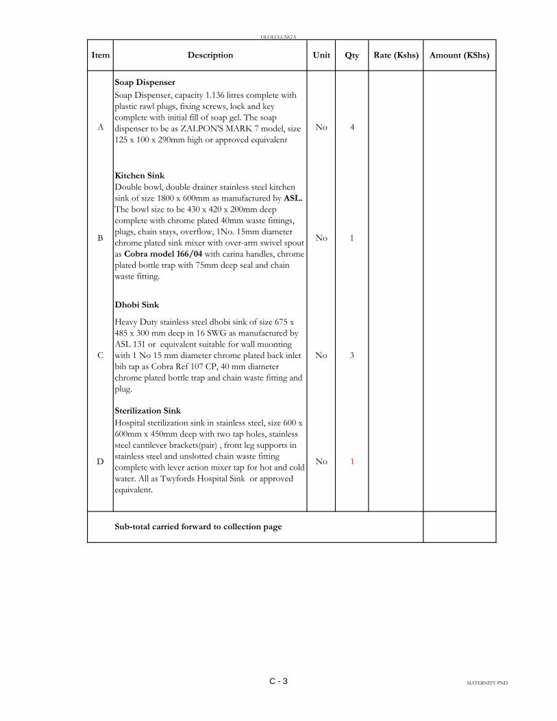
OLOLULUNG'A
Item Description Unit Qty Rate (Kshs) Amount (KShs)
Soap Dispenser
A
Soap Dispenser, capacity 1.136 litres complete with
plastic rawl plugs, fixing screws, lock and key
complete with initial fill of soap gel. The soap
dispenser to be as ZALPON'S MARK 7 model, size
125 x 100 x 290mm high or approved equivalent
No 4
Kitchen Sink
B
Double bowl, double drainer stainless steel kitchen
sink of size 1800 x 600mm as manufactured by ASL.
The bowl size to be 430 x 420 x 200mm deep
complete with chrome plated 40mm waste fittings,
plugs, chain stays, overflow, 1No. 15mm diameter
chrome plated sink mixer with over-arm swivel spout
as Cobra model 166/04 with carina handles, chrome
plated bottle trap with 75mm deep seal and chain
waste fitting.
No 1
Dhobi Sink
C
Heavy Duty stainless steel dhobi sink of size 675 x
485 x 300 mm deep in 16 SWG as manufactured by
ASL 131 or equivalent suitable for wall muonting
with 1 No 15 mm diameter chrome plated back inlet
bib tap as Cobra Ref 107 CP, 40 mm diameter
chrome plated bottle trap and chain waste fitting and
plug.
No 3
Sterilization Sink
D
Hospital sterilization sink in stainless steel, size 600 x
600mm x 450mm deep with two tap holes, stainless
steel cantilever brackets(pair) , front leg supports in
stainless steel and unslotted chain waste fitting
complete with lever action mixer tap for hot and cold
water. All as Twyfords Hospital Sink or approved
equivalent.
No 1
Sub-total carried forward to collection page
C - 3 MATERNITY PND

OLOLULUNG'A
Item Description Unit Qty Rate (Kshs) Amount (KShs)
Mirror
A
Mirror of size 1,200 x 600x 6mm thick, plugged and
screwed to wall with 6No. chrome plated dome
capped screws. The mirror shall rest against a layer of
5mm thick foam.
No 2
B
Mirror of size 600 x 600x 6mm thick, plugged and
screwed to wall with 6No. chrome plated dome
capped screws. The mirror shall rest against a layer of
5mm thick foam.
No 2
Scrub-Up
C Twyford Scrub-up Trough 2500mm long with Left
hand outlet Cat No. SS9122SS Complete with 3No.
wall mounted Lever action mixer taps Cat No.
SF1099CP 11/2Chrome plated Waste fitting and a s
trap
No 1
Flexible Tubing
D15mm diameter x 300mm long chrome plated
flexible connectors.No 11
Angle valve
EChrome plated Angle shut-off valve as Cobra or
approved equivalent84 No
Sluice Unit
F
Twyfords “Grafton B.P.S.” hopper cat.no.
FC4076WH loose-trap FC44612WH complete with
Vitreous china high level cistern 7.5 Litre capacity
with valveless fittings and reversible chain pull
CX7610WH, cistern supporting brackets
SR1300XX stainless steel flushpipe with spreader and
clips SS6020SS Combine bedpan and urinal bottle jet
with 1/2" lever handle taps, SF6504CP legs and
bearers for hopper SR3053XX sinks 760mm x
455mm FC1350WH chain and waste 11/2" chrome
plated WF4338CP waste pipe for the hopper
WF9685WH legs and bearers for sink SR3043XX
drain with anti-drip stip FC9684WH legs and bearers
for drain SR3052XX chrome plated extended bib
tap 1/2" SF5204CP Chrome plated Lever action
mixer tap flexible hose and handspray SF7053CP.
No 1
Sub-total carried forward to collection page
C - 4 MATERNITY PND
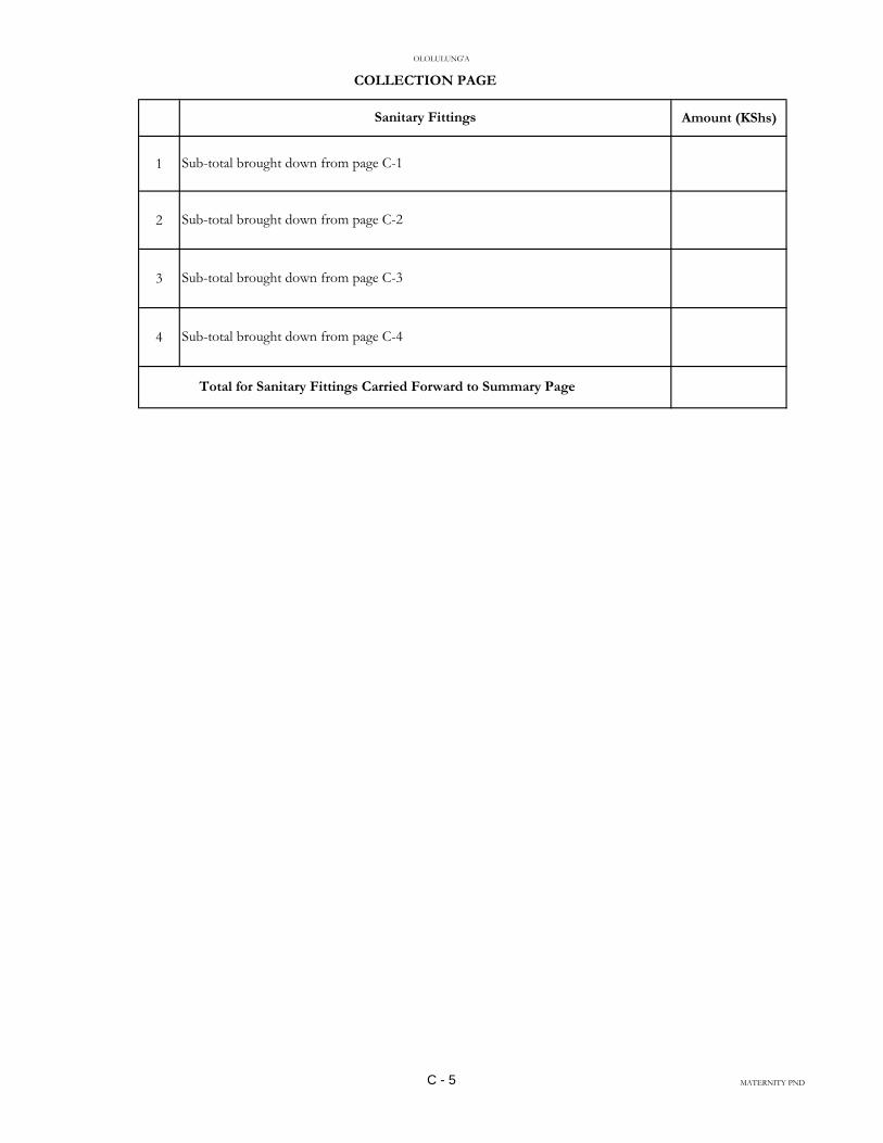
OLOLULUNG'A
Amount (KShs)
1
2
3
4
COLLECTION PAGE
Total for Sanitary Fittings Carried Forward to Summary Page
Sanitary Fittings
Sub-total brought down from page C-1
Sub-total brought down from page C-2
Sub-total brought down from page C-3
Sub-total brought down from page C-4
C - 5 MATERNITY PND
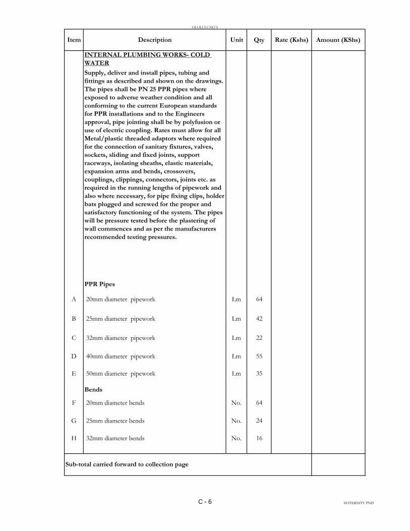
OLOLULUNG'A
Item Description Unit Qty Rate (Kshs) Amount (KShs)
INTERNAL PLUMBING WORKS- COLD
WATER
Supply, deliver and install pipes, tubing and
fittings as described and shown on the drawings.
The pipes shall be PN 25 PPR pipes where
exposed to adverse weather condition and all
conforming to the current European standards
for PPR installations and to the Engineers
approval, pipe jointing shall be by polyfusion or
use of electric coupling. Rates must allow for all
Metal/plastic threaded adaptors where required
for the connection of sanitary fixtures, valves,
sockets, sliding and fixed joints, support
raceways, isolating sheaths, elastic materials,
expansion arms and bends, crossovers,
couplings, clippings, connectors, joints etc. as
required in the running lengths of pipework and
also where necessary, for pipe fixing clips, holder
bats plugged and screwed for the proper and
satisfactory functioning of the system. The pipes
will be pressure tested before the plastering of
wall commences and as per the manufacturers
recommended testing pressures.
PPR Pipes
A 20mm diameter pipework Lm 64
B 25mm diameter pipework Lm 42
C 32mm diameter pipework Lm 22
D 40mm diameter pipework Lm 55
E 50mm diameter pipework Lm 35
Bends
F 20mm diameter bends No. 64
G 25mm diameter bends No. 24
H 32mm diameter bends No. 16
Sub-total carried forward to collection page
C - 6 MATERNITY PND
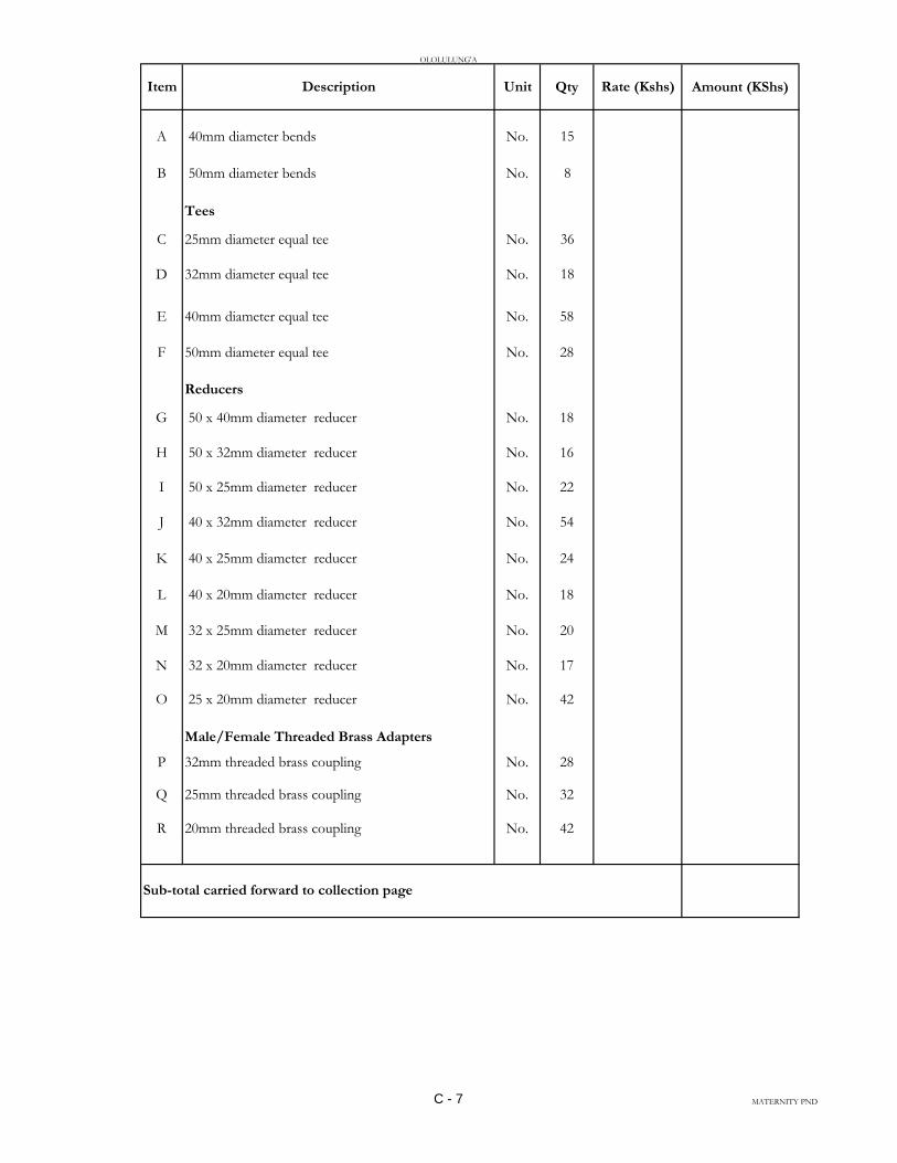
OLOLULUNG'A
Item Description Unit Qty Rate (Kshs) Amount (KShs)
A 40mm diameter bends No. 15
B 50mm diameter bends No. 8
Tees
C 25mm diameter equal tee No. 36
D 32mm diameter equal tee No. 18
E 40mm diameter equal tee No. 58
F 50mm diameter equal tee No. 28
Reducers
G 50 x 40mm diameter reducer No. 18
H 50 x 32mm diameter reducer No. 16
I 50 x 25mm diameter reducer No. 22
J 40 x 32mm diameter reducer No. 54
K 40 x 25mm diameter reducer No. 24
L 40 x 20mm diameter reducer No. 18
M 32 x 25mm diameter reducer No. 20
N 32 x 20mm diameter reducer No. 17
O 25 x 20mm diameter reducer No. 42
Male/Female Threaded Brass Adapters
P 32mm threaded brass coupling No. 28
Q 25mm threaded brass coupling No. 32
R 20mm threaded brass coupling No. 42
Sub-total carried forward to collection page
C - 7 MATERNITY PND
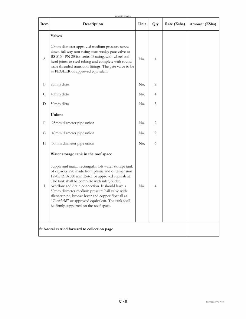
OLOLULUNG'A
Item Description Unit Qty Rate (Kshs) Amount (KShs)
Valves
A
20mm diameter approved medium pressure screw
down full way non-rising stem wedge gate valve to
BS 5154 PN 20 for series B rating, with wheel and
head joints to steel tubing and complete with round
male threaded transition fittings. The gate valve to be
as PEGLER or approved equivalent.
No. 4
B 25mm ditto No. 2
C 40mm ditto No. 4
D 50mm ditto No. 3
Unions
F 25mm diameter pipe union No. 2
G 40mm diameter pipe union No. 9
H 50mm diameter pipe union No. 6
Water storage tank in the roof space
I
Supply and inatall rectangular loft water storage tank
of capacity 920 made from plastic and of dimension
1270x1270x580 mm Rotor or approved equivalent.
The tank shall be complete with inlet, outlet,
overflow and drain connection. It should have a
50mm diameter medium pressure ball valve with
silencer pipe, bronze lever and copper float all as
“Glenfield” or approved equivalent. The tank shall
be firmly supported on the roof space.
No. 4
Sub-total carried forward to collection page
C - 8 MATERNITY PND

OLOLULUNG'A
Amount (KShs)
1
2
3
COLLECTION PAGE
Internal plumbing
Sub-total brought down from page C-6
Sub-total brought down from page C-7
Sub-total brought down from page C-8
Total for Internal Plumbing Carried Forward to Summary Page
C - 9 MATERNITY PND
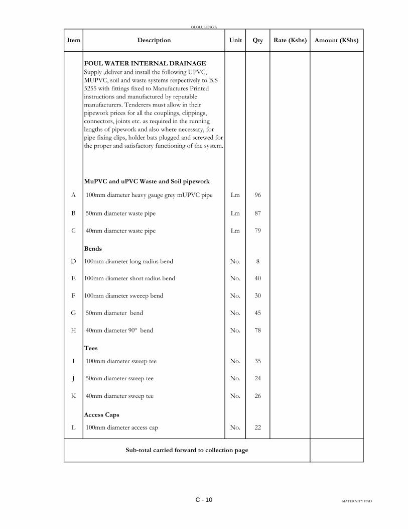
OLOLULUNG'A
Item Description Unit Qty Rate (Kshs) Amount (KShs)
FOUL WATER INTERNAL DRAINAGE
Supply ,deliver and install the following UPVC,
MUPVC, soil and waste systems respectively to B.S
5255 with fittings fixed to Manufactures Printed
instructions and manufactured by reputable
manufacturers. Tenderers must allow in their
pipework prices for all the couplings, clippings,
connectors, joints etc. as required in the running
lengths of pipework and also where necessary, for
pipe fixing clips, holder bats plugged and screwed for
the proper and satisfactory functioning of the system.
MuPVC and uPVC Waste and Soil pipework
A 100mm diameter heavy gauge grey mUPVC pipe Lm 96
B 50mm diameter waste pipe Lm 87
C 40mm diameter waste pipe Lm 79
Bends
D 100mm diameter long radius bend No. 8
E 100mm diameter short radius bend No. 40
F 100mm diameter sweeep bend No. 30
G 50mm diameter bend No. 45
H 40mm diameter 90º bend No. 78
Tees
I 100mm diameter sweep tee No. 35
J 50mm diameter sweep tee No. 24
K 40mm diameter sweep tee No. 26
Access Caps
L 100mm diameter access cap No. 22
Sub-total carried forward to collection page
C - 10 MATERNITY PND
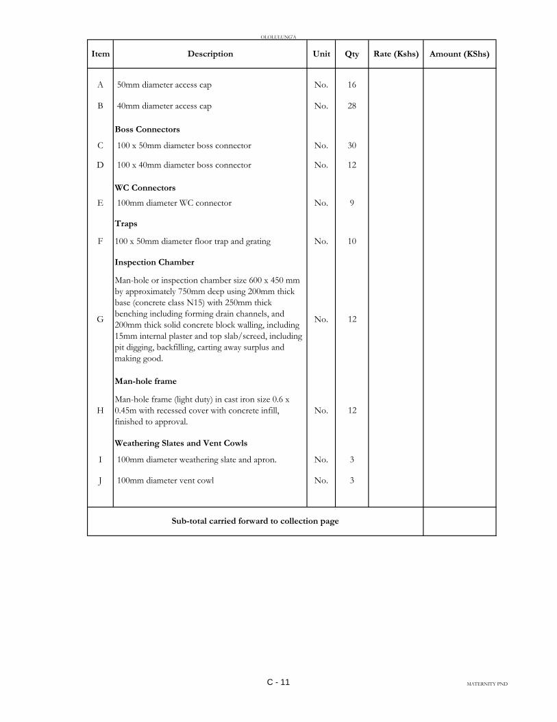
OLOLULUNG'A
Item Description Unit Qty Rate (Kshs) Amount (KShs)
A 50mm diameter access cap No. 16
B 40mm diameter access cap No. 28
Boss Connectors
C 100 x 50mm diameter boss connector No. 30
D 100 x 40mm diameter boss connector No. 12
WC Connectors
E 100mm diameter WC connector No. 9
Traps
F 100 x 50mm diameter floor trap and grating No. 10
Inspection Chamber
G
Man-hole or inspection chamber size 600 x 450 mm
by approximately 750mm deep using 200mm thick
base (concrete class N15) with 250mm thick
benching including forming drain channels, and
200mm thick solid concrete block walling, including
15mm internal plaster and top slab/screed, including
pit digging, backfilling, carting away surplus and
making good.
No. 12
Man-hole frame
H
Man-hole frame (light duty) in cast iron size 0.6 x
0.45m with recessed cover with concrete infill,
finished to approval.
No. 12
Weathering Slates and Vent Cowls
I 100mm diameter weathering slate and apron. No. 3
J 100mm diameter vent cowl No. 3
Sub-total carried forward to collection page
C - 11 MATERNITY PND

OLOLULUNG'A
Amount (KShs)
1
2
COLLECTION PAGE
Internal drainage
Sub-total brought down from page C-10
Sub-total brought down from page C-11
Total for Internal Drainage Carried Forward to Summary Page
C - 12 MATERNITY PND

OLOLULUNG'A
Item Description Unit Qty Rate (Kshs) Amount (KShs)
FIRE FIGHTING EQUIPMENT
Supply, deliver and install the following fire fighting
equipment in positions indicated on the contract
drawings or as shall be instructed by the Engineer.
Hose Reel
A
20mm diameter 36m long swimming type fire hose
reel complete with delivery valve, mild steel feed
pipe, isolation valve guide and all other accessories as
“ANGUS FIRE ARMOUR” or equal and approved.
No. 2
Hose Reel Pump
B
Fully automatic package unit water pressure booster
pumpset capable of delivering 2.3 litres/sec against a
static pressure head of 27M. The pumpset shall
comprise 2No. pumps (one duty, one standby),
mountings, control gear, pressure switch and
pneumatic vessel, all on a common frame. Control
shall be effected via a pressure switch through a
prewired control panel, which shall give automatic
changeover from duty to standby after every cycle of
operation. The controls shall also include motor
under-voltage/over voltage protection devices and
incorporate a float switch for protection against dry
running. The pumpset shall be pre-assembled
complete with pipework, and fittings(unions, water
strainers, isolation valsves, non-return valves,
etec)ready for connection to water tank outlet and to
the hose-reel supply pipework. The pumpset shall be
as 'Pullen Firepak' as manufactured by pullen pumps
ltd or equal and approved.
Set 1
Control Panel
C
Control panel for the above pumps with contactors,
over voltage anf under voltage protection relays,
start/stop push buttons and indicators lights. All this
shall be housed in a lockable cabinet(with integral
isolator) made from SWG 18 mild steel sheet that is
oven powder coated.
No 1
Sub-total carried forward to collection page
C - 13 MATERNITY PND
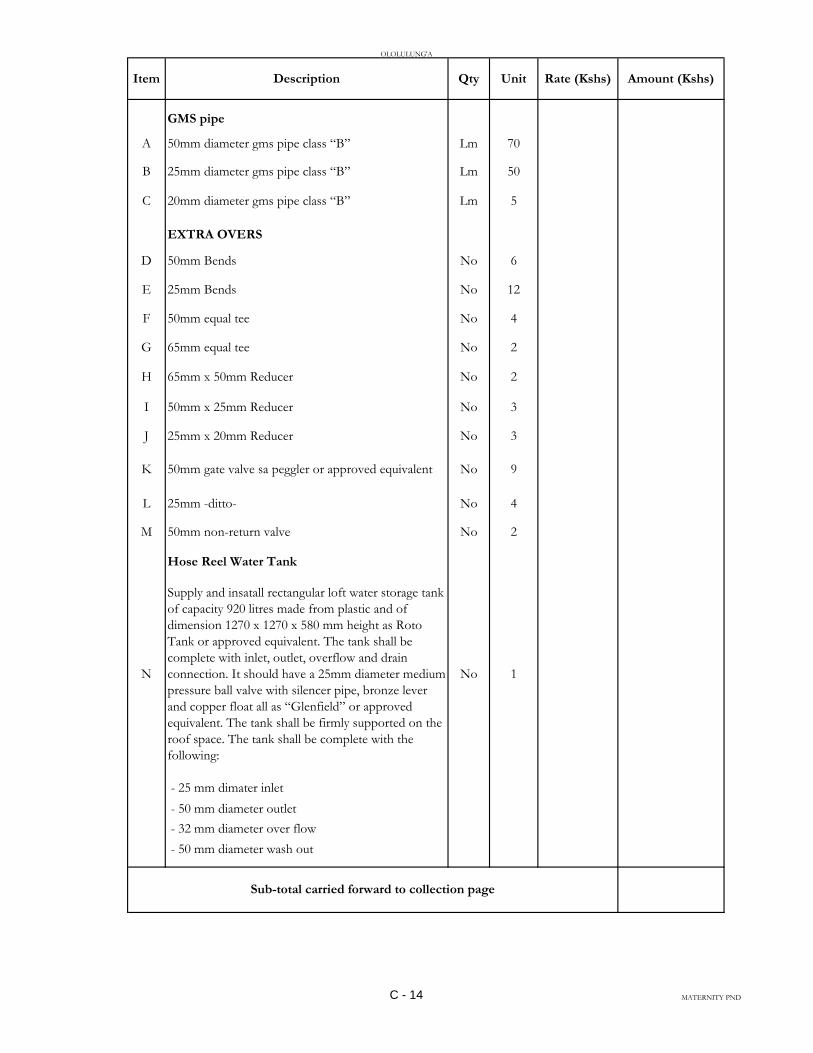
OLOLULUNG'A
Item Description Qty Unit Rate (Kshs) Amount (Kshs)
GMS pipe
A 50mm diameter gms pipe class “B” Lm 70
B 25mm diameter gms pipe class “B” Lm 50
C 20mm diameter gms pipe class “B” Lm 5
EXTRA OVERS
D 50mm Bends No 6
E 25mm Bends No 12
F 50mm equal tee No 4
G 65mm equal tee No 2
H 65mm x 50mm Reducer No 2
I 50mm x 25mm Reducer No 3
J 25mm x 20mm Reducer No 3
K 50mm gate valve sa peggler or approved equivalent No 9
L 25mm -ditto- No 4
M 50mm non-return valve No 2
Hose Reel Water Tank
N
Supply and insatall rectangular loft water storage tank
of capacity 920 litres made from plastic and of
dimension 1270 x 1270 x 580 mm height as Roto
Tank or approved equivalent. The tank shall be
complete with inlet, outlet, overflow and drain
connection. It should have a 25mm diameter medium
pressure ball valve with silencer pipe, bronze lever
and copper float all as “Glenfield” or approved
equivalent. The tank shall be firmly supported on the
roof space. The tank shall be complete with the
following:
No 1
- 25 mm dimater inlet
- 50 mm diameter outlet
- 32 mm diameter over flow
- 50 mm diameter wash out
Sub-total carried forward to collection page
C - 14 MATERNITY PND
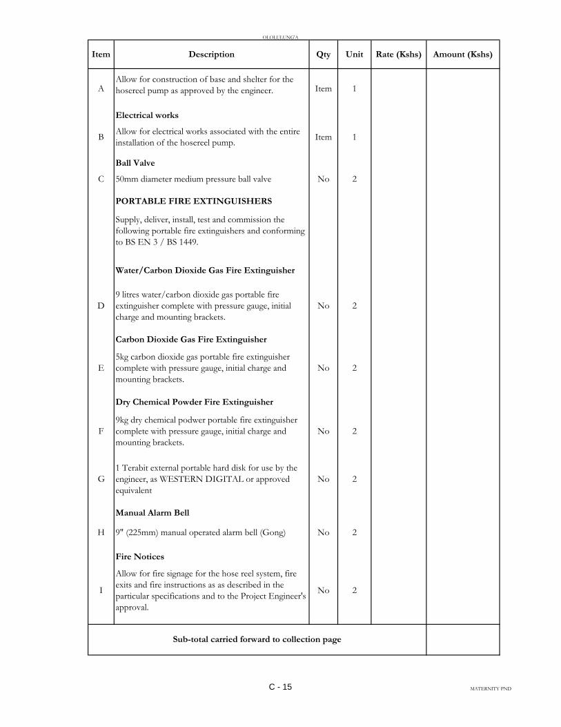
OLOLULUNG'A
Item Description Qty Unit Rate (Kshs) Amount (Kshs)
AAllow for construction of base and shelter for the
hosereel pump as approved by the engineer. Item 1
Electrical works
BAllow for electrical works associated with the entire
installation of the hosereel pump.Item 1
Ball Valve
C 50mm diameter medium pressure ball valve No 2
PORTABLE FIRE EXTINGUISHERS
Supply, deliver, install, test and commission the
following portable fire extinguishers and conforming
to BS EN 3 / BS 1449.
Water/Carbon Dioxide Gas Fire Extinguisher
D
9 litres water/carbon dioxide gas portable fire
extinguisher complete with pressure gauge, initial
charge and mounting brackets.
No 2
Carbon Dioxide Gas Fire Extinguisher
E
5kg carbon dioxide gas portable fire extinguisher
complete with pressure gauge, initial charge and
mounting brackets.
No 2
Dry Chemical Powder Fire Extinguisher
F
9kg dry chemical podwer portable fire extinguisher
complete with pressure gauge, initial charge and
mounting brackets.
No 2
G
1 Terabit external portable hard disk for use by the
engineer, as WESTERN DIGITAL or approved
equivalent
No 2
Manual Alarm Bell
H 9" (225mm) manual operated alarm bell (Gong) No 2
Fire Notices
I
Allow for fire signage for the hose reel system, fire
exits and fire instructions as as described in the
particular specifications and to the Project Engineer's
approval.
No 2
Sub-total carried forward to collection page
C - 15 MATERNITY PND

OLOLULUNG'A
Item Description Qty Unit Rate (Kshs) Amount (Kshs)
A
Allow for as installed drawings in hard copy plotted
on A1 paper and soft copy (CD-ROM and 8 Gb
Flash disk), 3 copies Item 1
Testing and Commissioning
B
Allow for testing and commissioning of the
plumbing and drainage installations to the
satisfaction of the Engineer.Item 1
Sub-total carried forward to collection page
C - 16 MATERNITY PND
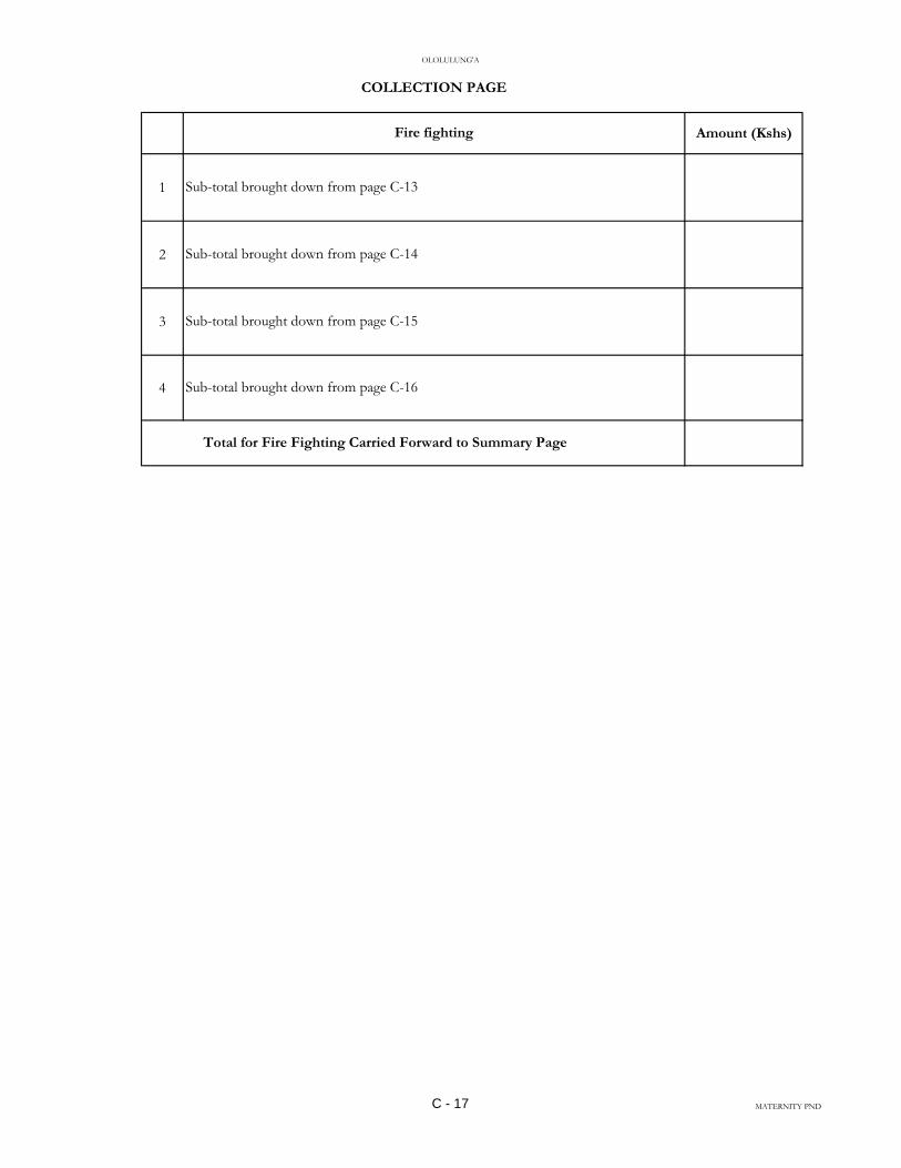
OLOLULUNG'A
Amount (Kshs)
1
2
3
4 Sub-total brought down from page C-16
Total for Fire Fighting Carried Forward to Summary Page
Sub-total brought down from page C-15
COLLECTION PAGE
Fire fighting
Sub-total brought down from page C-13
Sub-total brought down from page C-14
C - 17 MATERNITY PND

OLOLULUNG'A
Item Description Qty Unit Rate (Kshs) Amount (Kshs)
WATER TANKS
Supply, deliver and install the following;
Ground water storage tank
A
Cylindrical plastic water tank of capacity 10,000 litres
and having preferred dimensions 2360 mm diameter
and 2670 mm height. The tank to come complete
with tank cover and to be as "ROTO" tank or
approved equivalent. The tank shall be complete with
the following pipe connections:-
No 1
-40mm diameter overflow outlet
-32 mm diameter outlet
-32mm diameter inlet
High level water tank
B
Cylindrical plastic water tank of capacity 4,000 litres
and having preferred dimensions 1759 mm diameter
and 2020 mm height. The tank to come complete
with tank cover and to be as "ROTO" tank or
approved equivalent. The tank shall be complete with
the following pipe connections:-
No 1
-65mm diameter overflow outlet
-50 mm diameter outlet
-32mm diameter inlet
C Level Regulator/float switch No 1
D
Cabling 1.5 square mm control armoured cable from
high level tank to the control panel. The cable to run
in a 20 mm conduit.
Lm 50
E Water Level Indicator No 1
F External ladder from tank platform No 1
G 50mm diameter high pressure ball valve No 1
H
Galvanized steel tower 6 metres high capable of
holding 4,000 litre plastic water tank and with
features as described in the particular specifications.
No 1
IGalvanized tower ladder and protection cage of
approximately 12 metres high No 1
Sub-total carried forward to collection page
C - 18 MATERNITY PND
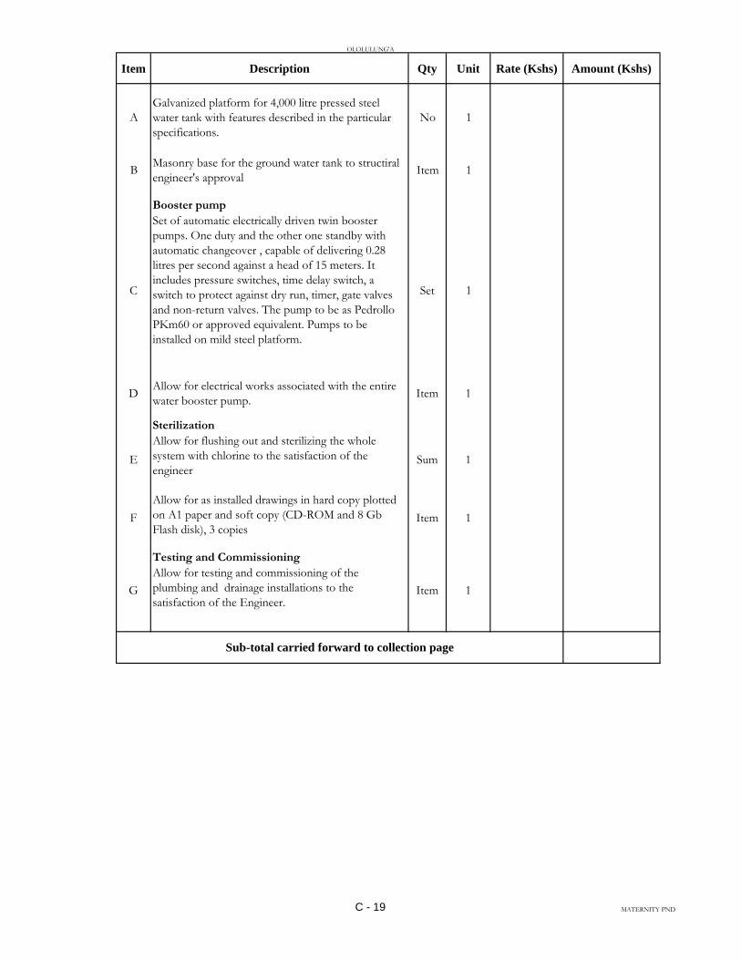
OLOLULUNG'A
Item Description Qty Unit Rate (Kshs) Amount (Kshs)
A
Galvanized platform for 4,000 litre pressed steel
water tank with features described in the particular
specifications.
No 1
BMasonry base for the ground water tank to structiral
engineer's approvalItem 1
Booster pump
C
Set of automatic electrically driven twin booster
pumps. One duty and the other one standby with
automatic changeover , capable of delivering 0.28
litres per second against a head of 15 meters. It
includes pressure switches, time delay switch, a
switch to protect against dry run, timer, gate valves
and non-return valves. The pump to be as Pedrollo
PKm60 or approved equivalent. Pumps to be
installed on mild steel platform.
Set 1
DAllow for electrical works associated with the entire
water booster pump.Item 1
Sterilization
E
Allow for flushing out and sterilizing the whole
system with chlorine to the satisfaction of the
engineerSum 1
F
Allow for as installed drawings in hard copy plotted
on A1 paper and soft copy (CD-ROM and 8 Gb
Flash disk), 3 copies Item 1
Testing and Commissioning
G
Allow for testing and commissioning of the
plumbing and drainage installations to the
satisfaction of the Engineer.Item 1
Sub-total carried forward to collection page
C - 19 MATERNITY PND
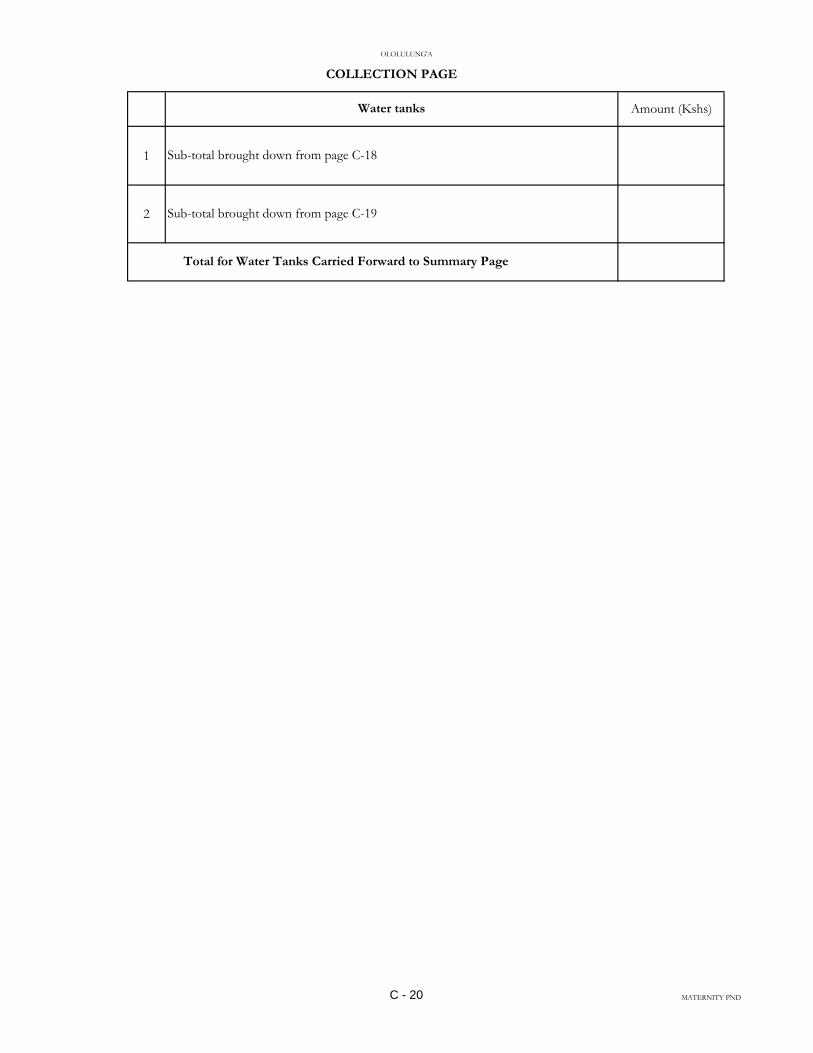
OLOLULUNG'A
Amount (Kshs)
1
2
COLLECTION PAGE
Water tanks
Sub-total brought down from page C-18
Sub-total brought down from page C-19
Total for Water Tanks Carried Forward to Summary Page
C - 20 MATERNITY PND

OLOLULUNG'A
Amount (Kshs)
1
2
3
4
5
6 400,000.00
Total for Foul Water Drainage BroughtDown from Page C-12 ………..…
Total for Water Tanks Brought Down from Page C-20 …………….…..
TOTAL FOR PLUMBING AND DRAINAGE CARRIED TO MAIN SUMMARY
PAGE
SUMMARY PAGE
DESCRIPTION
Total for Fire Fighting Equipment Brought Down from Page C-17 ……..
Allow for Contingency …………………………………………..…….
Total for Sanitary Fittings Brought Down from Page C-5………………
Total for Internal Plumbing Brought Down from Page C-9 ………..……
C - 21 MATERNITY PND

ELECTRICAL INSTALLATION WORKS

TABLE OF CONTENTS
TITLE PAGE
Contents .................................................................................................................... (i)
SECTION D: General Specifications of Materials and Works.....................................D/1--D/22
SECTION E: Schedule of Contract Drawings...............................................................E/1
SECTION F: Particular Specifications of Materials and Works...................................F/1
SECTION G: Schedule of Unit Rates........................................................................... G/1--G/2
SECTION H: Bills of Quantities................................................................................ . H/1--H/10
SECTION I: Technical Schedule of Items to be Supplied............................................I/1--I/2
SECTION J: Commissioning Guide...................................................................................J/1--J/6
(i)

SECTION D
GENERAL SPECIFICATION
OF
MATERIALS AND WORKS

GENERAL SPECIFICATIONS OF MATERIALS AND WORKS
2.1 General
2.2 Standard of Materials
2.3 Workmanship
2.4 Procurement of Materials
2.5 Shop Drawings
2.6 Record Drawings
2.7 Regulations and Standards
2.8 Setting out Works
2.9 Position of Electrical Plant and Apparatus
2.10 M.C.B Distribution Panels and Consumer Units
2.11 Fused Switchgear and Isolators
2.12 Conduits and Conduit Runs
2.13 Conduit Boxes and Accessories
2.14 Labels
2.15 Earthing
2.16 Cables and Flexible Cords
2.17 Armoured PVC Insulated and Sheathed Cables
2.18 Cable Supports; Markers and Tiles
2.19 PVC Insulated Cables
2.20 Heat Resisting Cables
2.21 Flexible Cords
D-1

2.22 Cable Ends and phase Colours
2.23 Cable Insulation Colours
2.24 Sub-circuit Wiring
2.25 Space Factor
2.26 Insulation
2.27 Lighting Switches
2.28 Sockets and Switched sockets
2.29 Fused Spur Boxes
2.30 Cooker Outlets
2.31 Connectors
2.32 Lampholders
2.33 Lamps
2.34 lighting Fittings Street lighting Lanterns
2.35 Position of Points and Switches
2.36 Street/Security Lighting Columns
2.37 Timing Control Switch
2.38 Wiring System for Street Lighting
2.39 Metal control Pillar
2.40 Current Operated Earth leakage circuit breaker
2.41 MV Switchboard
2.42 Steel Conduits and Steel Trunking
2.43 Testing on Site
D-2.

2.1 SHOP DRAWINGS
Before manufacture or Fabrication is commenced the sub-contractor shall submit Two
copies of detailed drawings of all control pillars, meter cubicles, medium voltage
switchboards including their components showing all pertinent information including
sizes, capacities, construction details, etc, as may be required to determine the suitability
of the equipment for the approval of the Engineer. Approval of the detailed drawings
shall not relieve the sub-contractor of the full responsibility of errors or the necessity of
checking the drawings himself or of furnishing the materials and equipment and
performing the work required by the plans and specifications.
2.2 RECORD DRAWINGS
These diagrams and drawings shall show the completed installation including sizes, runs
and arrangements of the installation. The drawings shall be to scale not less than 1 :50
and shall include plan views and section.
The drawings shall include all the details which may be useful in the operation,
maintenance or subsequent modifications or extensions to the installation.
Three sets of diagrams and drawings shall be provided, all to the approval of the
Engineer.
One coloured set of line diagrams relating to operating and maintenance instructions
shall be framed and, mounted in a suitable location.
2.3 REGULATIONS AND STANDARDS
All work executed by the Sub-contractor shall comply with the current edition of the
“Regulations” for the Electrical Equipment of Buildings, issued by the Institution of
Electrical Engineers, and with the Regulations of the Local Electricity Authority.
Where the two sets of regulations appear to conflict, they shall be clarified with the
Engineers. All materials used shall comply with relevant Kenya Bureau of Standards
Specification.
D-3.

2.4 SETTING OUT WORK
The sub-contractor at his own expenses; is to set out works and take all measurements
and dimensions required for the erection of his materials on site; making any
modifications in details as may be found necessary during the progress of the works,
submitting any such modifications or alterations in detail to the Engineer before
proceeding and must allow in his Tender for all such modifications and for the provision
of any such sketches or drawings related thereto.
2.5 POSITIONS OF ELECTRICAL PLANT AND APPARATUS
The routes of cables and approximate positions of switchboards etc, as shown on the
drawings shall be assumed to be correct for purpose of Tendering, but exact positions of
all electrical Equipment and routes of cables must be agreed on site with the Engineer
before any work is carried out.
2.6 MCB DISTRIBUTION PANELS AND CONSUMER UNITS
All cases of MCB Panels and consumer units shall be constructed in heavy gauge sheet
with hinged covers.
Removable undrilled gland plates shall be provided on the top and bottom of the cases.
Miniature circuit breakers shall be enclosed in moulded plastic with the tripping
mechanism and arc chambers separated and sealed from the cable terminals.
The operating dolly shall be tripfree with a positive movement in both make and break
position. Clear indication of the position of the handle shall be incorporated.
The tripping mechanism shall be on inverse characteristic to prevent tripping in
temporary overloads and shall not be affected by normal variation in ambient
temperature.
A locking plate shall be provided for each size of breaker; A complete list of circuit
details on typed cartridge paper glued to stiff cardboards and covered with a sheet of
perspex, and held in position with four suitable fixings, shall be fitted to the inner face
of the lids of each distribution panel. The appropriate MCB ratings shall be stated on
the circuit chart against each circuit in use: Ivorine labels shall be secured to the
insulation barriers in such a manner as to indicate the number of the circuits shown on
the circuit chart.
Insulated barriers shall be fitted between phases, and neutrals in all boards, and to
shroud live parts.
Neutral cables shall be connected to the neutral bar in the same sequence as the phase
cables are connected to the MCB‟s. This shall also apply to earth bars when installed.
D-4.
2.7 FUSED SWITCHGEAR AND ISOLATORS
All fused switchgear and isolators whether mounted on machinery, walls or industrial
panels shall conform to the requirements of KS 04 – 226 PART: 1: 1985.
All contacts are to be fully shrouded and are to have a breaking capacity on manual
operations as required by KS 04 – 182 : 1980.
Fuse links for fused switches are to be of high rupturing capacity cartridge type,
conforming to KS 04 – 183 : 1978.
Isolators shall be load breaking/fault making isolators.
Fused switches and isolators are to have separate metal enclosures. Mechanical
interlocks are to be provided between the door and main switch operating mechanism so
arranged that the door may not be opened with the switch in the „ON‟ position.
Similarly; it shall not be possible to close the switch with the door open except that
provision to defeat the mechanical interlock and close the switch with the door in the
open position for test purposes. The „ON‟ and „OFF‟ positions of all switches and
isolators shall be clearly indicated by a mechanical flag indicator or similar device. In
T.P & N fused switch units, bolted neutral links are to be fitted.
2.8 CONDUITS AND CONDUIT RUNS
Conduit systems are to be installed so as to allow the loop-in system of wiring:
All conduits shall be black rigid super high impact heavy gauge class „A‟ PVC in
accordance with KS 04 – 179: 1988 and IEE Regulations. No conduit less than 20mm
in diameter shall be used anywhere in this installation.
Conduit shall be installed buried in plaster work and floor screed except when run on
wooden or metal surface when they will be installed surface supported with saddles
every 600mm. Conduit run in chases shall be firmly held in position by means of
substantial pipe hooks driven into wooden plugs.
The Sub-contractors attention is drawn to the necessity of keeping all conduits entirely
separate from other piping services such as water and no circuit connections will be
permitted between conduits and such pipes.
All conduits systems shall be arranged wherever possible to be self-draining to switch
boxes and conduit outlet points for fittings:
The systems, when installed and before wiring shall be kept plugged with well fitting
plugs and when short conduit pieces are used as plugs, they shall be doubled over and
tied firmly together with steel wire; Before wiring all conduit systems shall be carried
out until the particular section of the conduit installation is complete in every respect.
D-5.

The sets and bends in conduit runs are to be formed on site using appropriate size
bending springs and all radii of bends must not be less than 2.5 times the outside
diameter of the conduit. No solid or inspection bends, tees or elbows will be used.
Conduit connections shall either be by a demountable (screwed up) assembly or
adhesive fixed and water tight by solution. The tube and fittings must be clean and free
of all grease before applying the adhesive. When connections are made between the
conduit and switch boxes, circular or non-screwed boxes, care shall be taken that no
rough edges of conduit stick out into the boxes.
Runs between draw in boxes are not to have more than two right angle bends or their
equivalent . The sub-contractor may be required to demonstrate to the Engineers that
wiring in any particular run is easily withdrawable and the sub-contractor may, at no
extra cost to the contract; be required to install additional draw-in boxes required. If
conduit is installed in straight runs in excess of 6000mm, expansion couplings as
manufactured by Egatube shall be used at intervals of 6000mm.
Where conduit runs are to be concealed in pillars and beams, the approval of the
Structural Engineer, shall be obtained. The sub-contractor shall be responsible for
marking the accurate position of all holes, chases etc, on site, or if the Engineer so
directs, shall provide the Main Contractor with dimensional drawings to enable him t o
mark out and form all holes and chases. Should the sub-contractor fail to inform the
main contractor of any inaccuracies in this respect they shall be rectified at the sub-
contractors expense.
It will be the Sub-contractors responsibility to ascertain from site, the details of
reinforced concrete or structural steelwork and check from the builder‟s drawings the
positions of walls, structural concrete and finishes. No reinforced concrete or steelwork
may be drilled without first obtaining the written permission of the Structural Engineer.
The drawings provided with these specifications indicate the appropriate positions only
of points and switches, and it shall be the Sub-Contractors responsibility to mark out
and centre on site the accurate positions where necessary in consultation with the
Architect and the Engineer. The sub-contractor alone shall be responsible for the
accuracy of the final position.
2.13 CONDUIT BOXES AND ACCESSORIES
All conduit outlets and junction boxes are to be either malleable iron and of standard
circular pattern of the appropriate type to suit saddles being used or super high impact
PVC manufactured to KS 04 – 179 : 1983.
D-6.
Small circular pattern boxes are to be used with conduits up to and including 25mm
outside diameter. Rectangular pattern adaptable boxes are to be used for conduits of
32mm outside diameter and larger. For drawing in of cables in exposed runs of conduit,
standard pattern through boxes are to be used:
Boxes are to be not less than 50mm deep and of such dimensions as will enable the
largest appropriate number of cables for the conduit sizes to be drawn in without
excessive bending.
Outlet boxes for lighting fittings are to be of the loop-in type where conduit installation
is concealed and the sub-contractor shall allow one such box per fitting, except where
fluorescent fittings are specified when two such boxes per fitting shall be fitted flush
with ceiling and if necessary fitted with break joint rings. Pattresses shall be fitted
where required to outlets on surface conduit runs.
Adaptable boxes are to of PVC or mild steel (of not less than 12swg) and black
enamelled or galvanised finish according to location. They shall be of square or oblong
shape location. They shall be of square or oblong shape complete with lids secured by
four 2 BA brass roundhead screws; No adaptable box shall be less than 75mm x 75mm
x 50mm or larger than 300mm x 300mm x 75mm and shall be adequate in depth in
relation to the size of conduit entering it. Conduits shall only enter boxes by means of
conduit bushes.
2.14 LABELS
Labels fitted to switches and fuseboards;-
(i) Shall be Ivorine engraved black on white.
(ii) Shall be secured by R.H brass screws of same manufacturing throughout.
(iii) Shall be indicated on switches:-
a) Reference number of switch
b) Special current rating
c) Item of equipment controlled
(iv) Shall indicate on MCB panels
a) Reference number
b) Type of board, i.e;, lighting, sockets, etc,.
c) Size of cable supplying panel
d) where to isolate feeder cable
(v) Shall be generally not less than 75mm x 50mm.
D-7.

2.15 EARTHING
The earthing of the installation shall comply with the following requirements;-
(i) It shall be carried out in accordance with the appropriate sections of the current
edition of the Regulations, for the Electrical Equipment of Buildings issued by
Institute of Electrical Engineers of Great Britain.
(ii) At all main distribution panels and main service positions a 25mm x 3mm
minimum cross sectional area Copper tape shall be provided and all equipment
including the lead sheath and armouring of cables, distribution boards and metal
frames shall be bonded thereto.
(iii) The earth tape in Sub-clause (ii) shall be connected by means of a copper tape
or cable of suitable cross sectional area to an earth electrode which shall be a
copper earth rod (see later sub-clause).
(iv) All tapes to be soft high conductivity copper, untinned except where otherwise
specified and where run underground on or through walls, floors, etc., it shall be
served with corrosion resisting tape or coated with corrosion compound and
braided
(v) Where the earth electrode is located outside the building a removable test link
shall be provided inside the building as near as possible to the point of entry to
the tape, for isolating the earth electrode for testing purposes.
(vi) Earthing of sub-main equipment shall be deemed to be satisfactory where the
sub-main cables are M.I.C.S. or conduit with separate earth wire, and installation
is carried out in accordance with the figures stated in the current edition of the
I.E.E Regulations.
(vii) Where an earth rod is specified (see Sub-clause (iii) it shall be proprietary
manufacture, solid hand drawn copper of 15mm diameter driven into the ground
to a minimum depth of 3.6m . It shall be made up to 1.2m sections with internal
screw and socket joints and fitted with hardened steel tip and driving cap.
(viii) Earth plates will not be permitted
(ix) Where an earth rod is used the earth resistance shall be tested in the manner
described in the current edition of the IEE Regulations, by the Sub-Contractor in
the presence of the Engineer and the Sub-Contractor shall be responsible for the
supply of all test equipment.
(x) Where copper tape is fixed to the building structure it structure it shall be by
means of purpose made non-ferrous saddles which space the conductor away
from the structure a minimum distance of 20mm. Fixings, shall be made using
purpose made plugs; No fixings requiring holes to be drilled through the tape
will be accepted.
(xi) Joints in copper tape shall be tinned before assembly riveted with a minimum of
two copper rivets and seated solid.
D-8.
(xii) Where holes are drilled in the earth tape for connection to items of equipment
the effective cross sectional area must not be less than required to comply with
the IEE regulations.
(xiii) Bolts, nuts and washers for any fixing to the earth tape must be of non-ferrous
material.
(xiv) Attention is drawn to the need for the earthing metal parts of lighting fittings and
for bonding ball joint suspension in lighting fittings.
2.16 CABLES AND FLEXIBLE CORDS
All cables used in this Sub-Contract shall be manufactured in accordance with the
current appropriate Kenya standard Specification which are as follows:-
P.V.C. Insulated Cables and Flexible Cords - Ks 04-192:1988
PVC Insulated Armoured Cables - Ks 04-194:1990
Armouring of Electric cables - Ks 04-290:1987
The successful Sub-Contractor will, at the Engineers discretion be required to submit
samples of cables for the Engineers approval; the Engineer reserves the right to call for
the cables of an alternative manufacture without any extra cost being incurred.
P.V.C. insulated cables shall be 500/1000 volt grade. No cables smaller than 1.5mm²
shall be used unless otherwise specified. The installation and the finish of cables shall
be as detailed in later clauses. The colour of cables shall conform with the details stated
in the “Cable Braid and insulation Colours” Clause.
2.17 ARMOURED P.V.C. INSULATED AND SHEATHED CABLES:
Shall be 600/1000 volt grade manufactured to Ks 04-194:1988 and Ks 04-187/188 with
copper stranded conductors.
The wire armour of the cable shall be used wholly as an earth continuity conductor and
the resistance of the wire armour shall have a resistance not more than twice of the
largest current carrying conductor of the cable.
P.V.C./S.W.A./P.V.C. cables shall be terminated using “Telecom” “B” type or
approved equal or approved equal glands and a P.V.C. tapered sleeve shall be provided
to shroud each gland.
D-9.

Where cables rise from floor level to switchgear etc., they shall be protected by P.V.C.
conduit, to a height of 600mm from finished floor level, whether the cable is run on the
surface or recessed into the wall.
2.18 CABLE SUPPORTS, MARKERS AND TILES
All PVC/SWA/PVC cables run inside the building shall be fixed in rising ducts or on
ceilings by means of die cost cables hooks or clamps, or appropriate size to suit cables,
fixed by studs and back nuts to their channel sections.
Alternatively, fixing shall be by BICC claw type cleating system with die-cast cleats
and galvanized mild steel back straps or similar approved equal method. For one or
two cables run together the cleats shall be fixed a special channel section supports or
backstraps described above which shall in turn be secured to walls or ceilings of ducts
by rawbolts.
In excessively damp or corrosive atmospheric conditions special finishes may be
required and the Sub-contractor shall apply to the Engineer for further instructions
before ordering cleats and channels for such areas.
The above type of hooks and clamps and channels or cleats and blackstraps shall also be
used for securing cables in vertical ducts.
Cables supports shall be fixed at 600mm maximum intervals, the supports being
supplied and erected under this Sub-contract. Saddles shall not be used for supporting
cables nor any other type of fixing other than one of the two methods described above
or other system which has received prior approval of the Engineer;
Cables are to be kept clear of all pipe work and the Sub-contractor shall work in close
liaison with other services Sub-contractors.
The Sub-Contractor shall include for the provision of fixing of approved type coloured
slip on cables end markers to indicate permanently the correct phase and neutral colours
on all ends.
Provision shall be made for supplying and fixing approved non-corrosive metal cable
markers to be attached to the outside of all PVC/SWA/PVC cables at 15mm intervals
indicating cable size and distinction.
Where PVC/SWA/PVC cables are outside the building they shall be laid underground
750mm deep with protecting concrete interlocking cover tiles laid over which shall be
provided and laid under this Sub-contract.
All necessary excavations and reinstatement of ground including sanding or trenches
will be carried out by the Sub-Contractor, unless otherwise stated.
D-10.

2.19 PVC INSULATED CABLES Shall be of non-braided type as CMA reference 6491 x 600/1000/1000 volt grade
cables, or equal approved.
PVC cables shall conform to the details of the “Cables and Flexible cords” and “Cable
Braid and Insulation Colours” clauses.
2.20 HEAT RESISTING CABLES Final connections to cookers, water heaters, etc., shall be made using butyl rubber
insulated cable as CMA reference 610 butyl (Single core 600/1000 Volt).
This type of cable shall be used in all instances where a temperature exceeding 100°F,
but not exceeding 150°F is likely to be experienced. Final connections to all lighting
fittings (and other equipment where a temperature in excess of 150°c likely to be
experienced) shall be made using silicon rubber insulated cable or equal and approved.
2.21 FLEXIBLE CORDS
Shall be in accordance with the “Cable and Flexible Cords” clause. No cord shall be
less than 24/0.2mm in size unless otherwise specified.
Circular white twin TRS flex shall be used for plain pendant fittings up to 100 watts.
For all other types of lighting fittings the flexible cable shall be silicone rubber
insulated.
No polythene insulated flexible cable shall be used in any lighting fitting or other
appliance (see “Heat Resisting Cables” Clause 30).
2.22 CABLE ENDS AND PHASE COLOURS
All cable ends connected up in switchgear, MCB panels etc;, shall have the insulation
carefully cut back and the ends sealed with Hellerman rubber slip on cable end markers.
The markers shall be of appropriate phase colour for switch and all other live feeds to
the details of the “Cable Insulation Colours” clause. Black cable with black end
markers shall only be used for neutral cables.
2.23 CABLE INSULATION COLOURS Unless otherwise stated in later clauses the
insulation colours shall be in accordance with the following table.
Where other systems are installed the cable colours shall be in accordance with the
details stated in the appropriate clause.
D-11.
SYSTEM INSULATION COLOUR CABLE END
MARKER
Main and Sub-Main
a) Phase Red Red
b) Neutral Black Black
1) Sub-Circuits
Single Phase
a) Phase Red Red
b) Neutral Black Black
2.24 SUB-CIRCUIT WIRING
For all lighting and sockets wiring shall be carried out in the “looping in” system and
there shall be no joints whatsoever. No lighting circuits shall comprise more than 20
points when protected by 10A MCB. Cables with different cross-section area of copper
shall not be used in combination.
Lighting circuits P. V.C. cable 1.5mm² for all lighting circuits indicated on the drawing.
Power circuits P.V.C cable (minimum sizes).
(i) 2.5mm² for one, two or three 5Amp sockets wired in parallel.
(ii) 2.5mm² for one 15Amp socket.
(iii) 2.5mm² for maximum of ten switched 13 Amp sockets wired from 30 Amp
MCB.
The wiring sizes for lighting circuits and sockets are shown on the drawings. In such
cases, the sizes shown on the drawings shall prevail over the sizes specified.
Wiring sizes for other appliances shall be shown on the drawing or specified in later
clauses of this specification.
D-12.
2.25 SPACE FACTOR
The maximum number of cables that may be accommodated in a given size of conduit
or trunking or duct is not to exceed the number in Tables B.5 and B.6 or as stated in
Regulation B.91, B.117 and B.118 of the I.E.E Regulations whichever is appropriate.
2.26 INSULATION
The insulation resistance to earth and between poles of the whole wiring system, fittings
and lumps, shall not be less than the requirements of the latest edition of the I.E.E
Regulations. Complete tests shall be made on all circuits by the Sub-contractor before
the installations are handed over.
A report of all tests shall be furnished by the Sub-Contractor to the Engineer. The
Engineer will then check test with his own instruments if necessary.
2.27 LIGHTING SWITCHES
These shall be mounted flush with the walls, shall be contained in steel or alloy boxes
and shall be of the gangs ratings and type shown in the drawings. They shall be as
manufactured by M.K. Electrical Ltd., or other equal and approved to KS 04 – 247:
1988
2.28 SOCKETS AND SWITCHED SOCKETS
These shall be flush pattern in steel/pvc box and shall be of the gangs and type specified
in the drawings.
They shall be 13- Amp, 3-pin, shuttered, switched and as manufactured by “M.K.
Electrical Co. Ltd.”, or other approved equal to KS 04 – 246: 1987
2.29 FUSED SPUR BOXES
These shall be flush, D.P switched as in steel/pvc box and of type and make specified in
the drawings complete with pilot light and as manufactured by “M. K. Electrical
Company Ltd”, or other approved equal. KS 04 – 247: 1988
2.30 COOKER OUTLETS
These shall be flush mounted with 13-A switched socket outlet and neon indicator
Lamps.
The cooker control units shall be as manufactured by “M.K. Electrical Company Ltd”,
or other approved equal KS 04 – 247: 1988
D-13
2.31 CONNECTORS
Shall be specified in the drawings and appropriate rating. These shall be fitted at all
conduit box lighting point outlets for jointing of looped P.V.C cables with flexible
cables of specified quality.
2.32 LAMPHOLDERS
Shall be of extra heavy H.O skirted and shall be provided for every specified lighting
fitting and shall be B.C;, E.S;, or G.E.S as required. All E.S. and G.E.S. holders shall be
heavy brass type (except for plain pendants where the reinforced bakelite type shall be
used). The screwed cap of the E.S and G.E.S. holders shall be connected to the neutral.
Where lampholders are supported by flexible cable, the holders shall have “cord grip”
arrangements and in the case of metal shades earthing screws shall be provided on each
of the holders.
The Sub-Contractor must order the appropriate type of holder when ordering lighting
fittings, to ensure that the correct types of holders are provided irrespective of the type
normally supplied by the manufacturers.
2.33 LAMPS
All lamps shall be suitable for normal stated supply voltage and the number and sizes of
lamps detailed on the drawings shall be supplied and fixed. The Sub-Contractor must
verify the actual supply voltage with the supply authority before ordering the lamps.
Tungsten filament lamps shall be manufactured in accordance with KS 04 – 112:1978
for general service lamps and KS 04 – 307:1985 for lamps other than general services.
Tubular fluorescent lamps shall comply with KS 04 – 464:1982
Pearl lamps shall be used in all fittings unless otherwise specified.
2.34 LIGHTING FITTINGS AND STREET LIGHTING LANTERNS This Sub-Contract shall include for the provision, handling charges, taking the delivery,
safe storage, wiring (including internal wiring) assembling and erecting of all lighting
fittings shown on the drawings.
All fittings and pendants shall be fixed to the conduit boxes with brass R/H screws.
These to be in line with metal finish of fittings. The lighting fittings are detailed for the
purpose of establishing a high standard of finish and under no circumstances will
substitute fittings be permitted.
In case of rectangular shaped ceiling fittings, the extreme ends of the fittings shall be
secured to suitable support in addition to the central conduit box fittings. Supports shall
be provided and fixed by the Sub-Contractor.
D-14.
The whole of the metal work of each lighting fittings shall be effectively bonded to
earth. In the case of ball and/or knuckle joints short lengths of flexible cable shall be
provided, bonded to the metal work on either side of the joints. If the above provisions
are not made by the manufacturers -, the Sub-contractor shall include cost of additional
work necessary in his tender. See “Flexible Cords” clause for details of internal wiring
of lighting fittings. Minimum size of internal wiring shall be 20/0.20mm (23/0067).
Each lighting fitting shall be provided with number type and size of lamps as detailed on
the drawings. It is to be noted that some fittings are suspended as shown on the
drawings.
Where two or more points are shown adjacent to each other on the drawings, e.g socket
outlet and telephone outlet, they shall be lined up vertically or horizontally on the centre
lines of the units concerned
Normally, the units shall be lined up on vertical centre lines, but where it is necessary to
mount units at low level they shall be lined up horizontally.
2.35 POSITIONS OF POINTS AND SWITCHES
Although the approximate positions of all points are shown on the drawings, enquiry
shall be made as to the exact positions of all M.C.B panels, lighting points, socket
outlets etc, before work is actually commenced. The Sub-contractor must approach the
Architect with regard to the final layout of all lights on the ceiling and walls.
The Sub-contractor must consult with the Engineer in liaison with the Clerk of Works,
or the General Foreman on site regarding the positions of all points before fixing any
conduit etc. The Sub-Contractor shall be responsible for all alterations made necessary
by the non-compliance with the clause.
2.36 STREET/SECURITY OUTDOOR LIGHTING COLUMNS:
The column shall be at a minimum of 225mm in the ground on 75mm thick concrete
foundations and the pole upto 150mm shall be surrounded with concrete. The top
bracket and plain section of the columns shall be common to and interchangeable with
all brackets with maximum mismatching tolerance of 3mm between any pole and
bracket. After manufacture and before erection the columns shall be treated with an
approved mordant solution which shall be washed off and the whole allowed to dry.
Thereafter, the columns shall be painted with one undercoat and two coats of gloss paint
to an approved colour. All columns shall be complete with fused cut-outs.
2.37 TIMING CONTROL SWITCH
These shall be installed where shown on the drawings. Photocell timing control circuits
which will operate „on‟ with a specified level of darkness and „off‟ with a given level of
light. The initial adjustment will be done with approval of the Electrical Engineer.
D-15.
2.38 WIRING SYSTEM FOR STREETLIGHTING
Cables shall be as indicated on the drawings, and shall be laid in a cable trench 450mm
deep along the road sides and 600mm deep across the roads and 900mm away from the
road kerb or 1500mm away from the edges of the road. „Loop-in‟ and „Loop-out‟
arrangement shall be used at every pole. Wiring to the lanterns on each pole shall be
with 1.5mm² PVC twin insulated and sheathed cable with earth wire shall be laid at least
600mm below the finished road level on a compact bed of murram at least 50mm thick
and covered with a concrete surrounded 150mm thick.
2.39 METAL CONTROL PILLAR
These shall be metal clad and fabricated as per contract drawings and specification. The
Sub-Contractor shall supply, install, test and commission control pillars including
supplying, fixing connecting switchgears as detailed on the appropriate drawings.
2.40 CURRENT OPERATED EARTH LEAKAGE CIRCUIT BREAKER
Current operated earth leakage circuit breaker shall conform to B.S.S. 4293:68 rated at
240 volts D.P. 50 cycles A.C. Mains.
The breaker shall be provided with test switch and fitted in weather proof enclosure for
surface mounting. The rated load current and earth fault operating current shall be as
specified in the drawings. These shall be as manufactured by Crabtree, Siemens or
other equal and approved.
2.41 M.V. SWITCHBOARD AND SWITCHGEAR
The switchboard shall be manufactured in accordance with KS04-226 which co-
ordinates the requirements for electrical power switchgear and associated apparatus. It
is not intended that this K.S. should cover the requirements for specified apparatus for
which separate Kenyan Standard exist. All equipment and material used in the
switchboard shall be in accordance with the appropriate Kenya Standard.
The switchboard shall comprise the equipment shown on the drawings together with all
current transformers, auxiliary fuses, labels, small wiring and interconnections necessary for
the satisfactory operation of the switchboard
D-16.
Switchboard shall be of the flush fronted, enclosed, metal clad type with full front or rear
access as called for in the particular specifications, suitable for indoor use, sectionalized
as necessary to facilitate transport and erection. The maximum height of the switchboard
is to be approximately 2.0 meters. A suitable connection chamber containing all field
terminals shall be provided at the top or bottom of the switchboard as appropriate.
Before manufacture, the Sub-Contractor shall submit to the consulting Engineer for
approval of detailed drawings showing the layout, construction and connection of the
switchboard.
All bus-bars and bus-bar connections shall consist of high conductivity copper and be
provided in accordance with KS 04-226: 1985. The bus-bars shall be clearly marked
with the appropriate phase and neutral colours which should be red, yellow, blue for the
phases and black for neutral. The bus-bars shall be so arranged in the switchboard that
the extensions to the left and right may be made in the future with ease should the need
arise.
Small wiring, which will be neatly arranged and cleated, shall be executed in
accordance with B.S. 158 and the insulation of the wiring shall be colored according to
the phase or neutral connection.
Switches and fuse switches, shall be in strict accordance with KS04-183:1978 Class 2
switches. Means of locking the switch in the “OFF” position shall be provided.
All fuse switches shall comply with KS04-183:1978, PARTS 2 and 3 a fault rating at
least equal to the fault rating of the switchboard in which they are installed. Cartridge
fuse links to KS 04-183:1978 category A.C. 46, class Q1 and fusing factor not
exceeding 1.5 shall be supplied with each fused switch.
Mounting arrangements shall be such that individual complete fuse switches may be
disconnected and withdrawn when necessary without extensive dismantling work.
When switches are arranged in their formation all necessary horizontal and vertical
barriers shall be provided to ensure segregation from adjacent units. Means of locking
the switch in the “OFF” position shall be provided.
D-17.
2.42 STEEL CONDUITS AND STEEL TRUNKING
Conduits shall be of heavy gauge class “B” welded to Standard specification KS 04-
180:1985. In no case will conduit smaller than 20mm diameter be used on the works.
Conduits installed within buildings shall be black enameled finish except where
specified otherwise. Where installed externally or in damp conditions they shall be
galvanised. Conduit fittings, accessories or equipment used in conjunction with
galvanised conduits shall also be galvanised or otherwise as approved by the service
engineer.
Metal trunking shall be fabricated from mild steel of not less than 18 swg. All sections
of trunking shall be rigidly fixed together and attached to the framework or fabric or the
building at intervals of not less than 1.2m. Joint trunking shall not overhang fixing
points by more than 0.5m.
All trunking shall be made electrically continuous by means of 25 x 3mm copper links
across each joint and where the trunking is galvanised, the links shall be made by
galvanised flat iron strips.
All trunking fittings (i.e. Bends, tees, etc) shall leave the main through completely clear
of obstructions and continuously open except through walls and floors at which points
suitable fire resisting barriers shall be provided as may be necessary. The inner edge of
bends and tees shall be chamfered where cables larger than 35mm² are employed.
Where trunking passes through ceilings and walls the cover shall be solidly fixed to
150mm either side of ceilings and floors and 50mm either side of walls.
Screws and bolts securing covers to trunking or sections of covers together shall be
arranged so that damage to cables cannot occur either when fixing covers or when
installing cables in the trough.
Where trunking is used to connect switchgear of fuseboards, such connections shall be
made by trunking fittings manufactured for this purpose and not by multiple conduit
couplings.
Where vertical sections of trunking are used which exceed 4.5m in length, staggered tie
off points shall be provided at 4.5m intervals to support the weight of cables.
Unless otherwise stated, all trunking systems shall be painted as for conduit.
D-18.

Where a wiring system incorporates galvanized conduit and trunking, the trunking shall be deemed to be galvanized unless specified otherwise.
The number of cables to be installed in trunking shall be such as to permit easy drawing
in without damage to the cables, and shall in no circumstances be such that a space
factor of 45% is exceeded.
Conduit and trunking shall be mechanically and electrically continuous. Conduit shall
be tightly screwed between the various lengths so that they butt at the socketed joints.
The internal edges of conduit and all fittings shall be smooth, free from burrs and other
defects. Oil and any other insulating substance shall be removed from the screw
threads; where conduits terminate in fuse-gear, distribution boards, adaptable boxes,
non-spouted switchboxes, etc., they shall, unless otherwise stated, be connected thereto
by means of smooth bore male brass bushes, compression washers and sockets. All
exposed threads and abrasions shall be painted using an oil paint for black enamelled
tubing and galvanising paint for galvanised tubing immediately after the conduits are
erected. All bends and sets shall be made cold without altering the section of the
conduit. The inner radius of the bed shall not be less than four (4) times the outside
diameter of the conduit. Not more than two right angle bends will be permitted without
the inter-position of a draw-in-box. Where straight runs of conduit are installed, draw-
in-boxes shall be provided at distances not exceeding 15mm. No tees, elbows, sleeves,
either of inspection or solid type, will be permitted.
Conduit shall be swabbed out prior to drawing in cables, and they shall be laid so as to
drain of all condensed moisture without injury to end connections.
Conduits and trunking shall be run at least 150mm clear of hot water and steam pipes,
and at least 75mm clear of cold water and other services unless otherwise approved by
the services engineer.
All boxes shall conform to KS 04 – 668: 1986, to be of malleable iron, and black
enamelled or galvanised according to the type of conduit specified. All accessory boxes
shall have threaded brass inserts.
Box lids where required shall be heavy gauge metal, secured by means of zinc plated or
cadmium plated steel screws.
All adaptable boxes and lids of the same size shall be interchangeable.
Boxes used on surface work are to be tapped or drilled to line up with the conduit fixed
in distance type saddles allowing clearance between the conduit and wall without the
need for setting the conduit.
D-19.
Where used in conjunction with mineral insulated copper sheathed cable, galvanised
boxes shall be used and painted after erection.
Draw-in boxes in the floors are generally to be avoided but where they are essential they
must be grouped in positions approved by the services engineer and covered and by the
suitable floor traps, with non-ferrous trays and covers.
The floor trap covers are to be recessed and filled in with a material to match the floor
surface.
The Sub-contractor must take full responsibility for the filling in of all covers, but the
filling in material will be supplied and the filling carried out by the main building
contractor.
Where buried in the ground outside the building the whole of the buried conduit is to be
painted with two coats of approved bitumastic composition before covering up.
Where run on the surface, unpainted fittings and joints shall be painted with two coats of
oil bound enamel applied to rust and grease free metalwork.
2.43 TESTING ON SITE The Sub-contractor shall conduct during and at the completion of the installation and, if
required, again at the expiration of the maintenance period, tests in accordance with the
relevant section of the current edition of the Regulations for the electrical equipment of
buildings issued by the I.E.E of Great Britain, the Government Electrical Specification
and the Electric Supply Company‟s By-Laws.
(a) Tests shall be carried out to prove that all single pole switches are installed in the
„live‟ conductor.
(b) Tests shall be carried out to prove that all socket outlets and switched socket
outlets are connected to the „live‟ conductor in the terminal marked as such, and
that each earth pin is effectively bonded to the earth continuity system. Tests
shall be carried out to verify the continuity of all conductors of each „ring‟ circuit.
(c) Phase tests shall be carried out on completion of the installation to ensure that
correct phase sequence is maintained throughout the installation. Triplicate copies
of the results of the above tests shall be provided within 14 days of the witnessed
tests and the Sub-contractor will be required to issue to the service engineer the
requisite certificate upon completion as required by the regulations referred to
above.
D-20.
(d) Any faults, defects or omissions or faulty workmanship, incorrectly positioned or installed
parts of the installation made apparently by such inspections or tests shall be rectified by the
Sub-contractor at his own expense.
(e) The Sub-contractor shall provide accurate instruments and apparatus and all
labour required to carry out the above tests. The instruments and apparatus shall
be made available to the services engineer to enable him to carry out such tests as
he may require.
The Sub-contractor shall generally attend on other contractors employed on the project
and carry out such electrical tests as may be necessary.
The Sub-contractor shall test to the services engineer‟s approval and as specified
elsewhere in this specification or in standards and regulations already referred to, all
equipment, plant and apparatus forming part of the works and before connecting to any
power or other supply and setting to work.
Where such equipment, etc., forms part of or is connected to a system whether primarily
or of an electrical nature or otherwise ( e.g. air conditioning system) the Sub-contractor
shall attend on and assist in balancing, regulating testing and commissioning, or if
primarily an electrical or other system forming part of works, shall balance, regulate,
test and commission the system to the service engineer‟s approval.
D-21.

APPENDIX TO GENERAL SPECIFICATIONS OF MATERIALS AND WORKS
The electrical sub-contractor shall comply with the following:-
1. Government Electrical Specifications No. 1 and No. 2.
2. All requirements of Kenya Power and Lighting Company Limited, and
Communications Authority of Kenya (CA).
3. Be duly registered with National Construction Authority for Electrical installation works
with a valid annual practicing license.
4. Have a valid license from Energy Regulatory Commission for Electrical installation
works.
D-22.

SECTION E
SCHEDULE OF CONTRACT DRAWINGS

SCHEDULE OF CONTRACT DRAWINGS
.
DRAWING NO.
DRAWING TITLE
As will be issued by the Engineer
NOTE:
Tenderers are advised to inspect the electrical drawings at the office of the Chief
Engineer (Electrical) - State Department of Public Works, at Chief Engineer
(Electrical) office, Hill Plaza Building, Community area, Nairobi along Ngong road,
during normal working hours.
E/1

SECTION F
PARTICULAR SPECIFICATIONS
OF
MATERIALS AND WORKS
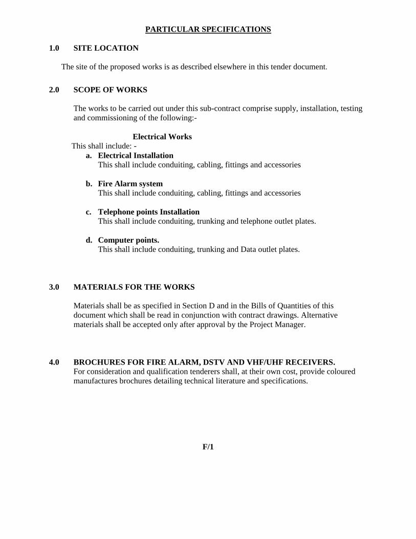
PARTICULAR SPECIFICATIONS
1.0 SITE LOCATION
The site of the proposed works is as described elsewhere in this tender document.
2.0 SCOPE OF WORKS
The works to be carried out under this sub-contract comprise supply, installation, testing
and commissioning of the following:-
Electrical Works
This shall include: -
a. Electrical Installation
This shall include conduiting, cabling, fittings and accessories
b. Fire Alarm system
This shall include conduiting, cabling, fittings and accessories
c. Telephone points Installation
This shall include conduiting, trunking and telephone outlet plates.
d. Computer points.
This shall include conduiting, trunking and Data outlet plates.
3.0 MATERIALS FOR THE WORKS
Materials shall be as specified in Section D and in the Bills of Quantities of this
document which shall be read in conjunction with contract drawings. Alternative
materials shall be accepted only after approval by the Project Manager.
4.0 BROCHURES FOR FIRE ALARM, DSTV AND VHF/UHF RECEIVERS.
For consideration and qualification tenderers shall, at their own cost, provide coloured
manufactures brochures detailing technical literature and specifications.
F/1

SECTION G
SCHEDULE OF UNIT RATES

SCHEDULE OF UNIT RATES
1. The tenderer shall insert unit rates against the items in the following schedules and may
add such other items as he considers appropriate.
2. The unit rates shall include for supply, transport, insurance, delivery to site, storage as
necessary, assembling, cleaning, installing, connecting, profit and maintenance in defects
liability and any other obligation under this contract.
3. The unit rates will be used to assess the value of additions or omissions arising from
authorised variations to the contract works.
4. Where trade names or manufacturer‟s catalogue numbers are mentioned in the
specification, the reference is intended as a guide to the type of article or quality of
material required. Alternative brands of equal and approved quality will be accepted.
G/1

SCHEDULE OF UNIT RATES
NO DESCRIPTION QTY UNIT UNIT RATE
1
2
3
4
5
6
7
8
9
10
11
Cables PVC SWA PVC Cables:-
a) 2 core 6mm2
b) 2 core 10mm2
c) 3 core 10mm2
d) 4 core 50mm2
e) 4 core 70mm2
f) 4 core 95mm2
g) 4 core 120mm2
6Way TPN distribution board as Crabtree or equivalent
12 Way TPN distribution board as Crabtree or
equivalent.
8Way SPN Consumer‟s unit as Crabtree or equivalent
80 A TPN isolator as Crabtree.
100 A TPN isolator as Crabtree.
240V-24 hour Time switch
100A Busbar Chamber
Security floodlight 150W(LED Type)
20A TPN RCBO
20A TPN Contactor
1
1
1
1
1
1
1
1
1
1
1
1
1
1
1
1
1
M
M
M
M
M
M
M
NO
NO
NO
NO
NO
NO
NO
NO
NO
NO
KSHS CTS
G2

SECTION H
BILLS OF QUANTITIES

BILLS OF QUANTITIES
A) PRICING OF PRELIMINARIES ITEMS
Prices will be inserted against item of preliminaries in the Contractor‟s Bills of Quantities and
specification. These Bills are designated as Bill No.1 in this Section. Where the Contractor fails
to insert his price in any item he shall be deemed to have made adequate provision for this
on various items in the Bills of Quantities. The preliminaries form part of this contract and
together with other Bills of Quantities covers for the costs involved in complying with all the
requirements for the proper execution of the whole of the works in the contract.
The Bills of Quantities are divided generally into three sections:
(a) Preliminaries – Bill No.1
Contractor‟s preliminaries are as per those described in section C – Contract
Preliminaries and General Conditions of Contract. The Contractor shall study the
conditions and make provision to cover their cost in this Bill. The number of preliminary
items to be priced by the Tenderer has been limited to tangible items such as site office,
temporary works and others. However the Tenderer is free to include and price any other
items he deems necessary taking into consideration conditions he is likely to encounter
on site.
(b) Installation Items – Other Bills
(i) The brief description of the items in these Bills of Quantities should in no way
modify or supersede the detailed descriptions in the contract Drawings,
conditions of contract and specifications.
(ii) The unit of measurements and observations are as per those described in
clause
1.0 5 of the section C.
(c) Summary
The summary contains tabulation of the separate parts of the Bills of Quantities carried
forward with provisional sum, contingencies and any prime cost sums included. The
Contract shall insert his totals and enter his grand total tender sum in the space provided
below the summary.
This grand total tender sum shall be entered in the Form of Tender provided elsewhere in
this document.
H/1-----------(a)

SPECIAL NOTES TO THE BILLS OF QUANTITES
1. The Bills of Quantities form part of the contract documents and are to be read in conjunction
with the contract drawings and general specifications of materials and works.
2. The prices quoted shall be deemed to include for all obligations under the sub-contract
including but not limited to supply of materials, labour, delivery to site, storage on site,
installation, testing, commissioning and all taxes (including 16% VAT and 3%
Withholding Tax).
In accordance with Government policy, 3% Withholding Tax shall be deducted from all
payments made to the tenderer, and the same shall be forwarded to the Kenya Revenue
Authority (KRA).
3. All prices omitted from any item, section or part of the Bills of Quantities shall be deemed
to have been included to another item, section or part.
4. The brief descriptions of the items given in the Bills of Quantities are for the purpose of
establishing a standard to which the sub-contractor shall adhere to. Otherwise alternative
brands of equal and approved quality will be accepted.
Should the sub-contractor install any material not specified here-in before receiving
approval from the Project Manager, the sub-contractor shall remove the material in question
and, at his own cost, install the proper material.
5. The grand total of prices in the price summary page must be carried forward to the Form of
Tender.
6. Tenderers must enclose, together with their submitted tenders, detailed coloured
manufacturer‟s Brochures detailing Technical Literature and specifications on all the
equipment they intend to offer.
H/1 –--------- (b)
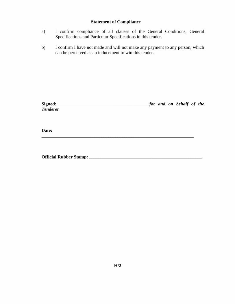
Statement of Compliance
a) I confirm compliance of all clauses of the General Conditions, General
Specifications and Particular Specifications in this tender.
b) I confirm I have not made and will not make any payment to any person, which
can be perceived as an inducement to win this tender.
Signed: _______________________________________for and on behalf of the
Tenderer
Date:
__________________________________________________________________
Official Rubber Stamp: _________________________________________________
H/2

SECTION I
TECHNICAL SCHEDULE
OF
ITEMS TO BE SUPPLIED

TECHNICAL SCHEDULE
The technical schedule shall be submitted by tenderers to facilitate and enable the Project
Manager to evaluate the tenders, especially where the tenderer intends to supply or has based his
tender sum on equipment which differs in manufacture, type or performance from the
specifications indicated by the Project Manager.
Any tender without this shall be disqualified.
I/1

TECHNICAL SCHEDULE OF ITEMS TO BE SUPPLIED
(To be completed by Tenderer)
ITEM DESCRIPTION TYPE/MAKE COUNTRY OF
ORIGIN
1.
2.
3.
4
5
6.
7.
8.
9.
10.
11.
12.
100A TP/N integral isolator
Lighting switches
Moulded Socket outlet Plates
Lighting fittings;
(i) 4 x 18 w fluorescent fitting.
(ii) 2 x 36w fluorescent fitting
(iii) 26 w, 2D Ceiling luminaire.
(iv) 2 x 14 w Bulk Head.
Distribution Boards/ Consumer Units
Telephone plates
Isolators
Trunking
MCCBs
8-Zone Fire alarm panel
Smoke Detectors.
Sounders.
I/2

SECTION J
ELECTRICAL TESTING AND COMMISSIONG GUIDE

Code: E/CG/01
REPUBLIC OF KENYA
STATE DEPARTMENT OF PUBLIC WORKS
ELECTRICAL & MECHANICAL (BS) ENGINEERING DEPARTMENTS
TESTING & COMMISSIONING GUIDE
FOR
ELECTRICAL INSTALLATION WORKS ON SITE
Issued by:
The Chief Engineer (Electrical),
State Department of Public Works,
P. O.BOX 41191 – 00100 GPO,
NAIROBI.
J/1

STATE DEPARTMENT OF PUBLIC WORKS
ELECTRICAL DEPARTMENT
TESTING AND COMMISSIONING OF ELECTRICAL INSTALLATION WORKS ON SITE.
PROJECT
NAME..........................................................................................................................................
........
W.P ITEM No..............................................................JOB No....................................................
The sub contractor shall test in accordance with the relevant section of IEE regulations, Rule 3 of
the Electrical Power Act for additional tests not covered by the regulations, Government
Electrical specifications I & II and the Kenya Power & Lighting Co. Ltd by-laws.
A PRELIMINARY CHECKS
The Engineer shall check to establish the following data:-
ITEM DESCRIPTION REMARKS
(i) Type of installation (New/Renovation/Addition/ to
existing installation)
(ii)
a) Power supply 240V/415V/11KV
b) Frequency of the mains supply
c) Installation power factor
…………………
…………………
…………………
(iii)
Method of Metering (New /Monitoring/Existing
meter)
(iv) Are Testing/Measuring instruments available
(v)
Are there maintenance/operational manuals for
specialized systems (if any)
(vi)
List of
‘as installed
drawings’
Drg No.
Description
J/2

B TESTS
ITEM TEST DESCRPTION OBSERVATIONS/
RESULTS
REMARKS
1 Tests shall be carried out to ensure:
a) All fuses and single pole switches are
installed in live conductor
b) All outlets and switched socket outlets
are connected to ‘LIVE’ conductor in
the Terminal marked so and each earth
pin effectively bonded to earth
continuity system
c) Verify continuity of all final conductors
of each ‘Ring’ circuit. (0.05 to 0.8Ω)
……………………..Ohms
d) All radial circuits emanate from
respective distribution boards/consumer
units and that they do not supply any
other Equipment
e) The correct phase sequence is
maintained throughout the installation
f) Effective ‘Discrimination’ in the
arrangement of protective devices. i.e.
a fault in the furthest power
point/Lighting point should not blow
or trip Fuses/MCBs respective in the
Meter board.
2 Inspect to ensure:
a) No terminal in the Ceiling Rose is ‘LIVE’
when the corresponding switch is in the
off position.
b) All conduit termination conduit boxes,
Consumer unit, DB’s and Adaptable
boxes have smooth edges and are
properly bushed.
c) All fixed metal works close to Electrical
installation are bonded to earth
continuity conductor.
d) All Fuse ways and Circuit breakers for
final sub circuits are properly labeled
J/3

B TESTS CONT’D
ITEM TEST DESCRPTION OBSERVATIONS/
RESULTS
REMARKS
3
Carry out the following tests:
a) Insulation Resistance tests
i) Between phases
a) R -Y
b) R -B
c) B-Y
ii) Phase to Neutral
a) R - N
b) R - N
c) B - N
iii) Phase to Earth
a) R - E
b) R -E
c) B -E
Minimum thresholds for above and for:
i) ELV circuits (SELV & PELV) = 0.25
MΩ
ii) LV Circuits up to 500V = 0.5 MΩ
iii) LV Circuits above 500V = 1 MΩ
………………….. ……MΩ
………………………..MΩ
………………………..MΩ
………………………..MΩ
………………….…….MΩ
………………….…….MΩ
………………………..MΩ
………………….…….MΩ
………………….…….MΩ
b) Earth continuity conductor
impedance
(0.005 to 2Ω)
………………………..Ohms
c) Earth fault Loop impedance
(0 - 2000 Ω)
……………………….Ohms
d) Earth Electrode resistance
(Less than 4Ω)
…………………….....Ohms
e) Earth Lead resistance
(Less than 4Ω)
……………………….Ohms
f) The operation of protection MCCBS
& MCBS (Tripping under faulty
conditions)
g) Check the mechanical toggling (make
& break) of all the switches to
installed accessories.
4 Underground cabling, Check for:
i) Continuity of the phases
ii) Factory tests done (avail
certification)
iii) Proper termination
iv) Route markers
J/4
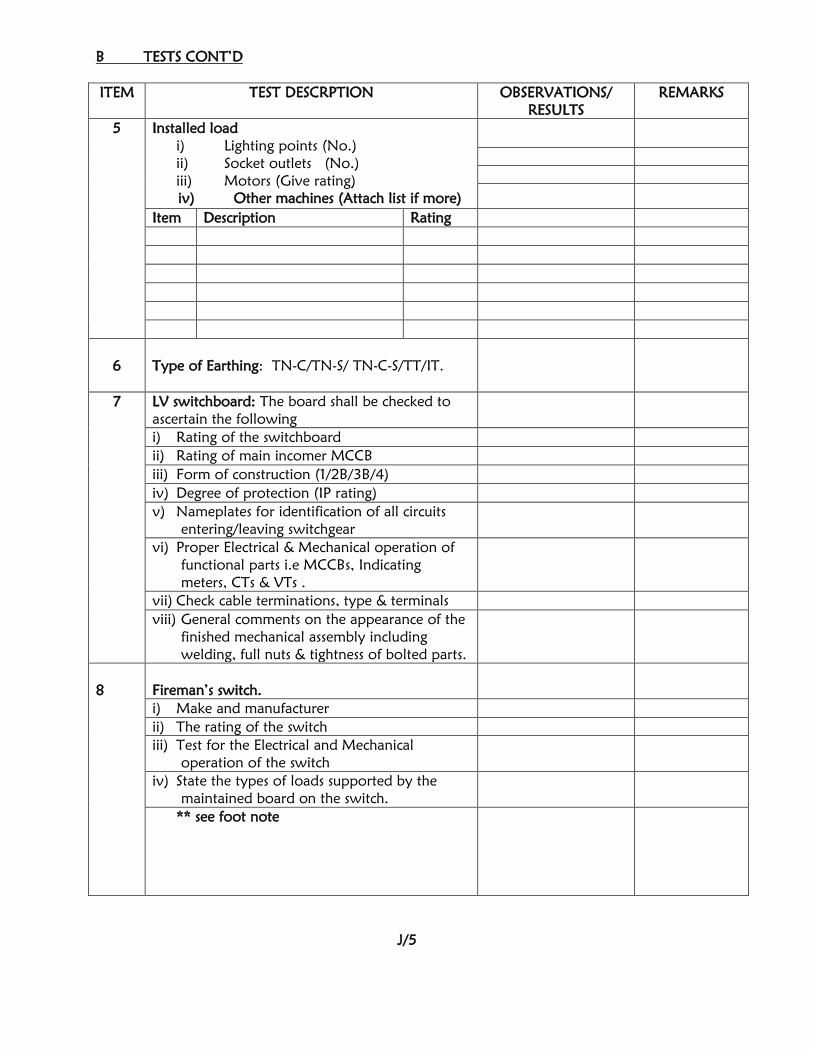
B TESTS CONT’D
ITEM TEST DESCRPTION OBSERVATIONS/
RESULTS
REMARKS
5 Installed load
i) Lighting points (No.)
ii) Socket outlets (No.)
iii) Motors (Give rating)
iv) Other machines (Attach list if more)
Item Description Rating
6
Type of Earthing: TN-C/TN-S/ TN-C-S/TT/IT.
7 LV switchboard: The board shall be checked to
ascertain the following
i) Rating of the switchboard
ii) Rating of main incomer MCCB
iii) Form of construction (1/2B/3B/4)
iv) Degree of protection (IP rating)
v) Nameplates for identification of all circuits
entering/leaving switchgear
vi) Proper Electrical & Mechanical operation of
functional parts i.e MCCBs, Indicating
meters, CTs & VTs .
vii) Check cable terminations, type & terminals
viii) General comments on the appearance of the
finished mechanical assembly including
welding, full nuts & tightness of bolted parts.
8
Fireman’s switch.
i) Make and manufacturer
ii) The rating of the switch
iii) Test for the Electrical and Mechanical
operation of the switch
iv) State the types of loads supported by the
maintained board on the switch.
** see foot note
J/5

General comments on the Electrical installation:-
Testing and Commissioning witnessed by:
S.D. P.W REPRESENTATIVE/ PROJECT ENGINEER:-
Name ………………….....................Designation……………………............
Sign………………………………… Date……………….…..……………….
CONTRACTOR’S REPRESENTATIVE:-
Name ………………….....................Designation……………………............
Sign………………………………… Date……………….…..…………….....
**If there are other defects noted, list them on a separate sheet and attach.
J/6

Item DescriptionQty Unit Rate (Ksh) Amount (Ksh)
Supply, install, test and commission the
following ;-
LIGHTING POINTS
1.01 Lighting points wired in 1.5 mm2
SC CU cables
drawn in concealed 20mm diameter HG P.V.C
conduits for:-
a) one way switching 68 No.
b) two way switching 33 No.
b) Unswitched 6 No.
SWITCHES
1.02 10Amps, switch plate as CLIPSAL, BG NEXUS or
approved equivalent as
a) one gang one way 20 No.
b) two gang one way 1 No.
c) three gang one way 1 No.
d) one gang two way 6 No.
e)Intermediate 4 No.
1.03 10Amps, Sparkless and splashproof
switches as CLIPSAL, BG, NEXUS or
approved equivalent
a) one gang one way 2 No.
b) one gang two way 2 No.
c) 2 Way, pull cord 2 No.
LIGHTING FITTINGS
1.04 Lighting fittings complete with bulbs or tubes as
follows:-
a) 1200mm, 2x 36 Watts batten fluorescent
fitting as THORN or approved equivalent.16 No.
b) 1200mm, 1x 36 Watts batten fluorescent fitting
as FITZGERALD,THORN or approved
equivalent.
20 No.
c)60Watts, spherical screw neck ball fitting as
THORN MTC 1060 or approved equivalent
16 No.
d) 1x18 Watts Bedhead fluorescent luminaire
complete with prismatic diffuser as THORN
PPD118 or approved equivalent.
12 No.
e) 1x8Watts, Single sided EXIT emergency lighting
luminaire as FITZGERALD, THORN or approved
equivalent.(TYPE EXIT)
5 No.
H/3
SCHEDULE NO. 1 - MATERNITY BLOCK
SUB TOTAL C/F TO PAGE No. H/4
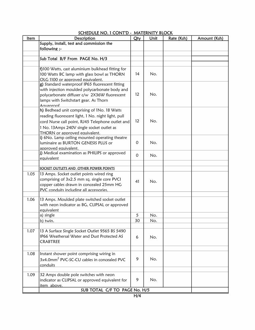
Item Description Qty Unit Rate (Ksh) Amount (Ksh)
Supply, install, test and commission the
following ;-
Sub Total B/F From PAGE No. H/3
f)100 Watts, cast aluminium bulkhead fitting for
100 Watts BC lamp with glass bowl as THORN
OLG 1100 or approved equivalent.
14 No.
g) Standard waterproof IP65 fluorescent fitting
with injection moulded polycarbonate body and
polycarbonate diffuser c/w 2X36W fluorescent
lamps with Switchstart gear. As Thorn
Aquaproof.
12 No.
h) Bedhead unit comprising of 1No. 18 Watts
reading fluorescent light, 1 No. night light, pull
cord Nurse call point, RJ45 Telephone outlet and
1 No. 13Amps 240V single socket outlet as
THORN or approved equivalent.
12 No.
i) 6No. Lamp ceiling mounted operating theatre
luminaire as BURTON GENESIS PLUS or
approved equivalent.
0 No.
j) Medical examination as PHILIPS or approved
equivalent
0 No.
SOCKET OUTLETS AND OTHER POWER POINTS
1.05 13 Amps. Socket outlet points wired ring
comprising of 3x2.5 mm sq. single core PVCI
copper cables drawn in concealed 25mm HG
PVC conduits including all accessories.
41 No.
a) single 5 No.
b) twin. 30 No.
1.07 13 A Surface Single Socket Outlet 9565 BS 5490
IP66 Weathersal Water and Dust Protected AS
CRABTREE
6 No.
1.08 Instant shower point comprising wiring in
3x4.0mm2
PVC-SC-CU cables in concealed PVC
conduits
9 No.
1.09 32 Amps double pole switches with neon
indicator as CLIPSAL or approved equivalent for
item above.
9 No.
H/4
SUB TOTAL C/F TO PAGE No. H/5
SCHEDULE NO. 1 CONT'D - MATERNITY BLOCK
1.06 13 Amps. Moulded plate switched socket outlet
with neon indicator as BG, CLIPSAL or approved
equivalent

Item Description Qty Unit Rate (Ksh) Amount (Ksh)
Supply, install, test and commission the
following ;-
Sub Total B/F From PAGE No. H/4
1.10 Cooker point wired in 3x6.0 mm2 PVC-SC-CU
cables drawn inside 25mm diameter concealed
heavy gauge PVC conduits compete with all
conduit accessories excluding the cooker element.
2 No.
1.11 45A Cooker control Unit complete with auxiliary
13A Socket outlet with Neon indicator as
Crabtree for approved equivalent
2 No.
1.12 Cooker Connector as Crabtree or approved
equivalent
2 No.
1.13 4burner point wired in 3x16.0 mm2 PVC-SC-CU
cables drawn inside 25mm diameter concealed
heavy gauge PVC conduits compete with all
conduit accessories excluding the cooker element.
1 No.
1.14 washer machine point wired in 3x16.0 mm2 PVC-
SC-CU cables drawn inside 25mm diameter
concealed heavy gauge PVC conduits compete
with all conduit accessories excluding the cooker
element.
1 No.
1.15 tumbler machine point wired in 3x16.0 mm2
PVC-SC-CU cables drawn inside 25mm diameter
concealed heavy gauge PVC conduits compete
with all conduit accessories excluding the cooker
element.
1 No.
H/5
SUB TOTAL C/F PAGE H/6
SCHEDULE NO. 1 CONT'D - MATERNITY BLOCK

Item Description Qty Unit Rate (Ksh) Amount (Ksh)
Supply, install, test and commission the
following ;-
Sub Total B/F From PAGE No. H/5
1.16 Chest Ironer power point wired in 3x16.0 mm2
PVC-SC-CU cables drawn inside 25mm diameter
concealed heavy gauge PVC conduits compete
with all conduit accessories excluding the cooker
element.
1 No.
1.17 Air Conditioner point comprising wiring in
5x4.0mm2 PVC-SC-CU cables in
concealed PVC conduits from DB 'D'
2 No.
1.18 63Amps SPN Isolator as CLIPSAL or approved
equivlent.
6 No.
1.19 Fan extract points comprising wiring in
3x2.5mm2 PVC-SC-CU cables in concealed PVC
conduits from DB 'D'
2 No.
1.20 Sterelizer points comprising wiring in 3x2.5mm2
PVC-SC-CU cables in concealed PVC conduits
from DB 'D' to sluice rooms
1 No.
1.21 20 Amps double pole switches with neon
indicator as CLIPSAL or approved equivalent.
3 No.
TELEPHONE/DATA AND TV WORKS
1.2216 SWG, (300 x 300 x 100) mm
3
galvanised steel
draw box for telephone/data works.
1 No.
1.23 Telephone/Data outlet point comprising of
concealed 20 mm dia. HG PVC conduits plus 1.5
mm2
single core draw wire.
15 No.
H/6
SUB TOTAL C/F PAGE H/7
SCHEDULE NO. 1 CONT'D - MATERNITY BLOCK

Item Description Qty Unit Rate (Ksh) Amount (Ksh)
Supply, install, test and commission the
following ;-
Sub Total B/F From PAGE No. H/6
1.24 RJ45, Data/Telephone Moulded plate as BG,
CLIPSAL or approved equivalent.
a) Single. 0 No.
b) twin. 15 No.
1.25 TV outlet point complete with wiring in CO-
AXIAL cable drawn in concealed HG PVC conduit
including moulded plates
4 No.
DISTRIBUTION BOARDS
1.26 12ways TP&N, flush mounted distribution boards
( A) complete with 100A integral isolator as
HAGER or approved equivalent complete with
all accessories but excluding MCBs.
2 No.
1.27 MCB’s for item above
(a) 10A, SP 6 No.
(b) 20A, SP 10 No.
(c) 32A SP 6 No.
(d) 45A SP 2 No.
(e) 63A SP 5 No.
(f) 63A TP 3 No.
(g) Blanking plates 34 No.
SUB-MAIN POWER DISTRIBUTION
1.28 50 mm2
4Core PVC/SWA/PVC Copper cables
drawn in duct from power house to LV Sub-
board
100 LM
1.29 The following items for item 1.28 above:-
a) Trenching to a depth of a minimum of
700mm 90 LM
b) Tiling with 'HATARI 'tiles 90 LM
c) Back filling of the trenches 90 LM
1.30 30A/30mA ELCB as HAGER or approved
equivalent
1 No.
H/7
SUB TOTAL C/F PAGE H/8
SCHEDULE NO. 1 CONT'D - MATERNITY BLOCK

Item Description Qty Unit Rate (Ksh) Amount (Ksh)
Supply, install, test and commission the
following ;-
Sub Total B/F From PAGE No. H/7
LV SUB-BOARD
1.31 415 Volts, Metal clad, Wall mounting LV Sub-
board with 300 Amperes TPN bus bars fully
wired for one incoming MCCB, 8No. TP
outgoing MCCBs as detailed in the drawings
including testing, provision for earthing and
labeling the board complete with all fixing
marterials and accessories.
1 item
1.32 The folowing MCCBs as HAGER for item 1.31
above:-
a) 200A TPN incomer 1 No.
b) 80A TP 1 No.
c) 100A TP 1 No.
d) TPN Spare ways 8 No.
EARTHING.
a) 15 mm x 1800 mm earth rod as FURSE cat.
No. RB 105. 2 No.
b) 15 mm dia. Driving stud as FURSE cat.No.
ST100. 2 No.
c) Rod to tape clamp as FURSE. 2 No.
d) Concrete inspection pit as FURSE cat.
No.PT005. (or a well made 320mm x
2 No.
e) 25x3mm copper tape 20 LM
FIRE ALARM SYSTEM.
1.34 Flush mounted 4 Zone, Fire alarm control panel
complete with Battery and charger as MENVIER
MF9304L or approved equivalent
1 No.
1.35 power point wired radial comprising of 3x2.5
mm sq. Heat resistant single core PVCI copper
cables drawn in concealed 20mm HG PVC
conduits for item 1.35 above.
1 No.
1.37 Conventional low profile LED sounder beacon as 4 No.
H/8
1.33 Earthing of the LV Sub-board above, comprising
of the following:-
1.36 Fire alarm points wired in 3x2.5mm2
Heat
resistant SC PVC copper cables drawn in
concealed HG PVC conduits
14 No.
SUB TOTAL C/F TO COLLECTION PAGE H/9
SCHEDULE NO. 1 CONT'D - MATERNITY BLOCK

Item Description Qty Unit Rate (Ksh) Amount (Ksh)
Supply, install, test and commission the
following ;-
Sub Total B/F From PAGE No. H/8
1.38 Smoke detectors as MENVIER or approved 14 No.
1.40 Fire break glass Manual call point unit as
MENVIER or approved equivalent complete with
a packet of 5 spare glasses, a packet of 5 spare
test keys, a spare back box and a hinged cover.
4 No.
FIREMAN'S SWITCH
NURSE CALL SYSYTEM
1.43 Nurse call system points comprising of wiring in 6
core PVC insulated copper cable drawn in
concealed 20mm dia. HG conduits.
12 No.
1.44 Wall mounted over door lights for Nurse call
system.
2 No.
1.45 Nurse call system pull cord call switch on
bedhead unit
12 No.
1.46 Nurse call/reset switch on bedhead unit 12 No.
1.47 Nurse call system ceiling pull cord call switch in
toilet area
5 No.
1.48 Nurse call/reset switch in toilet area 5 No.
H/9
1 No.
1.49 250 VAC 50 HZ, flush mounted Nurse call
control panel with a minimum of 24 No. patient
stations, alarm sounder, lamp test facility for the
dome lights and LEDs, continuous supervision of
addressable devices to Engineer's approval.
1 No.
SUB TOTAL C/F TO SUMMARY PAGE H/10
SCHEDULE NO. 1 CONT'D - MATERNITY BLOCK
1.42 Firemans switch as MENVIER or approved
equivalent.
1.41 Fireman's switch circuit comprising of 3x2.5 mm2
Heat resistant single core PVCI copper cables
drawn in concealed 20mm HG PVC conduits
from the MV Switchboard to the switch complete
with all fixing materials necessary to the Incomer.
20 LM
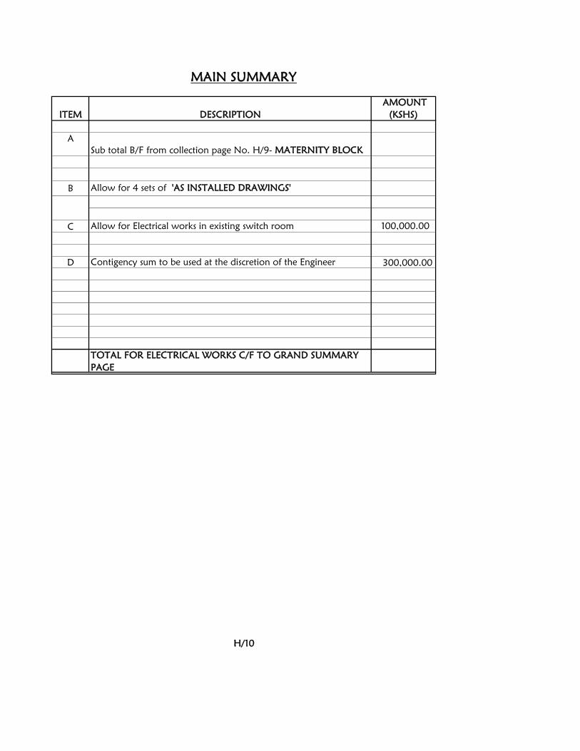
B
C 100,000.00
D 300,000.00
TOTAL FOR ELECTRICAL WORKS C/F TO GRAND SUMMARY
PAGE
H/10
Allow for 4 sets of 'AS INSTALLED DRAWINGS'
Allow for Electrical works in existing switch room
Contigency sum to be used at the discretion of the Engineer
MAIN SUMMARY
ITEM DESCRIPTION
AMOUNT
(KSHS)
A
Sub total B/F from collection page No. H/9- MATERNITY BLOCK
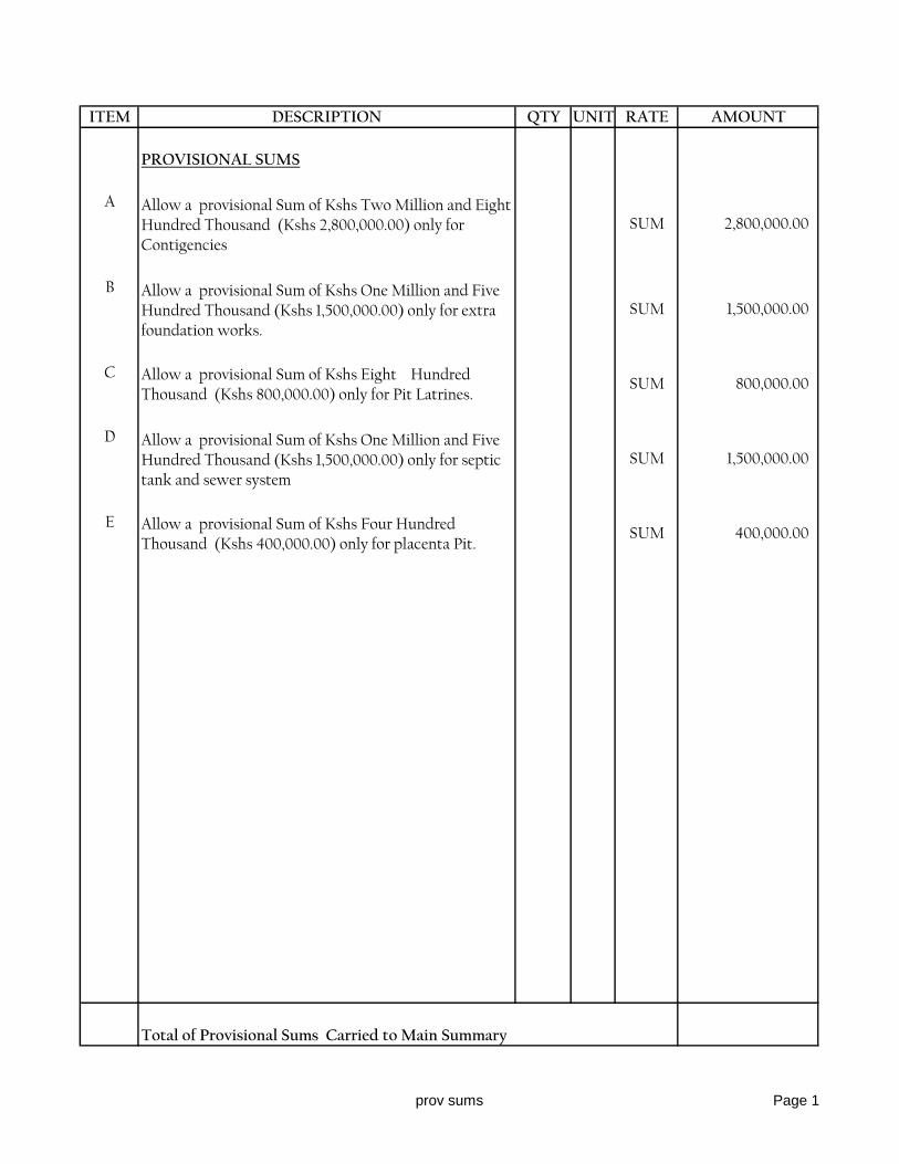
ITEM DESCRIPTION QTY UNIT RATE AMOUNT
PROVISIONAL SUMS
A Allow a provisional Sum of Kshs Two Million and Eight Hundred Thousand (Kshs 2,800,000.00) only for Contigencies
SUM 2,800,000.00
B Allow a provisional Sum of Kshs One Million and Five Hundred Thousand (Kshs 1,500,000.00) only for extra foundation works.
SUM 1,500,000.00
C Allow a provisional Sum of Kshs Eight Hundred Thousand (Kshs 800,000.00) only for Pit Latrines.
SUM 800,000.00
D Allow a provisional Sum of Kshs One Million and Five Hundred Thousand (Kshs 1,500,000.00) only for septic tank and sewer system
SUM 1,500,000.00
E Allow a provisional Sum of Kshs Four Hundred Thousand (Kshs 400,000.00) only for placenta Pit.
SUM 400,000.00
Total of Provisional Sums Carried to Main Summary 7,000,000.00
prov sums Page 1
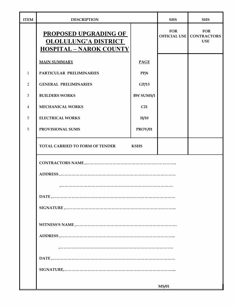
ITEM DESCRIPTION SHS SHS
PROPOSED UPGRADING OF
OLOLULUNG’A DISTRICT
HOSPITAL – NAROK COUNTY
FOR
OFFICIAL USE
FOR
CONTRACTORS
USE
MAIN SUMMARY PAGE
1 PARTICULAR PRELIMINARIES PP/6
2 GENERAL PRELIMINARIES GP/13
3 BUILDERS WORKS BW SUMS/1
4 MECHANICAL WORKS C21
5 ELECTRICAL WORKS H/10
5 PROVISIONAL SUMS PROV/01
TOTAL CARRIED TO FORM OF TENDER KSHS
CONTRACTORS NAME ,……………………………………………………………..
ADDRESS ,………………………………………………………………………………
,…………………………………………………………………………….
DATE ,……………………………………………………………………………………
SIGNATURE ,…………………………………………………………………………...
WITNESS'S NAME ,…………………………………………………………………….
ADDRESS ,……………………………………………………………………………...
,……………………………………………………………………………..
DATE ,……………………………………………………………………………………
SIGNATURE,…………………………………………………………………………....
MS/01